Collimating lenses from non-Euclidean transformation optics
10
PAPER Collimating lenses from non-Euclidean transformation optics To cite this article: Kan Yao et al 2012 New J. Phys. 14 023011 View the article online for updates and enhancements. You may also like Liquid crystal director fields in three- dimensional non-Euclidean geometries Jean-François Sadoc, Rémy Mosseri and Jonathan V Selinger - Modeling and Optimization of Layer-by- Layer Structures S A Lychev, G V Kostin, K G Koifman et al. - Non-Euclidean Newtonian cosmology John D Barrow - Recent citations Designing a wideband dielectric polygonal directional beam antenna using the ray inserting method Mohammad Mahdi Taskhiri and Saeed Fakhte - Broadband unidirectional behavior of electromagnetic waves based on transformation optics XiaoFei Zang et al - Inhomogeneous field in cavities of zero index metamaterials Yangyang Fu et al - This content was downloaded from IP address 121.157.14.62 on 20/01/2022 at 14:56
Transcript of Collimating lenses from non-Euclidean transformation optics
PAPER
Collimating lenses from non-Euclideantransformation opticsTo cite this article: Kan Yao et al 2012 New J. Phys. 14 023011
View the article online for updates and enhancements.
You may also likeLiquid crystal director fields in three-dimensional non-Euclidean geometriesJean-François Sadoc, Rémy Mosseri andJonathan V Selinger
-
Modeling and Optimization of Layer-by-Layer StructuresS A Lychev, G V Kostin, K G Koifman etal.
-
Non-Euclidean Newtonian cosmologyJohn D Barrow
-
Recent citationsDesigning a wideband dielectric polygonaldirectional beam antenna using the rayinserting methodMohammad Mahdi Taskhiri and SaeedFakhte
-
Broadband unidirectional behavior ofelectromagnetic waves based ontransformation opticsXiaoFei Zang et al
-
Inhomogeneous field in cavities of zeroindex metamaterialsYangyang Fu et al
-
This content was downloaded from IP address 121.157.14.62 on 20/01/2022 at 14:56

T h e o p e n – a c c e s s j o u r n a l f o r p h y s i c s
New Journal of Physics
Collimating lenses from non-Euclideantransformation optics
Kan Yao1,2, Xunya Jiang2 and Huanyang Chen1,3
1 School of Physical Science and Technology, Soochow University,Suzhou, Jiangsu 215006, People’s Republic of China2 The State Key Laboratory of Functional Materials for Informatics,Shanghai Institute of Microsystem and Information Technology,Chinese Academy of Sciences, Shanghai 200050, People’s Republic of ChinaE-mail: [email protected], [email protected] and [email protected]
New Journal of Physics 14 (2012) 023011 (9pp)Received 27 November 2011Published 6 February 2012Online at http://www.njp.org/doi:10.1088/1367-2630/14/2/023011
Abstract. Based on non-Euclidean transformation optics, we design a thinmetamaterial lens that can achieve wide-beam radiation by embedding a simplesource (a point source in the three-dimensional (3D) case or a line current sourcein the 2D case). The scheme is performed on a layer-by-layer geometry to convertcurved surfaces in the virtual space into flat sheets, which pile up and form theentire lens in the physical space. Compared to previous designs, the lens does nothave extreme material parameters. Simulation results confirm its functionality.
Contents
1. Introduction 22. Non-Euclidean transformation 23. Discussion 54. Conclusion 8Acknowledgments 9References 9
3 Author to whom any correspondence should be addressed.
New Journal of Physics 14 (2012) 0230111367-2630/12/023011+09$33.00 © IOP Publishing Ltd and Deutsche Physikalische Gesellschaft

2
1. Introduction
Various achievements in metamaterials in the past decade have enabled the unconventionalcontrol of electromagnetic fields: for example, perfect imaging [1] and directive emission [2].More recently, by reaching the ultimate optical illusion—the invisibility cloak [3, 4]—trans-formation optics attracted great attention and soon became an active topic. In simple terms,transformation optics utilizes the form-invariance property of Maxwell’s equations, whichensures that a spatial coordinate transformation can be interpreted as (or equivalent to) theeffect of a substitution of media. This fact provides a way to manipulate electromagneticfields on both wave and ray scales, facilitating the design of new materials and advanceddevices [5]. Besides the fascinating prospects of perfect imaging and invisibility, many practicalinstruments, for example lenses to collimate, bend, split or shift beams, have also been proposedas applications of metamaterials. It has been demonstrated that a point source embedded ina slab of near-zero index material radiates energy only in a narrow cone [2]. Later, the useof non-Euclidean transformation optics inspired more solutions. By setting radius-dependentbranch cuts, a spherical antenna can focus light into a needle-sharp beam [6]. The conventionaltransformation method is particularly straightforward when producing wide beams with highdirectivity, since arbitrary wavefronts can be assigned to flat ones [7–11]. However, the designof metamaterial lenses seems to face a natural dilemma, namely the dilemma that when the lensis tuned to be relatively thin (compared to the width of the lens or beam), the material parametersalways require extreme values [2, 6–10] and sometimes a wide source [9], whereas the deviceswill become thick if the singularities are removed [11].
In this paper, we discuss a way to achieve directive radiation via a thin lens madeof transformation media. The transformation, which is based on a three-dimensional (3D)extension of the stereographic projection on 2D manifolds, maps the wavefronts within a spheregradually onto a flat sheet and limits the thickness of the device to a quarter of its width.Meanwhile, as no singular point is involved, all material parameters avoid extreme values.Holding the same geometry in cross section, this scheme should also be valid for the 2D case,and numerical simulations confirm this deduction.
2. Non-Euclidean transformation
We begin by introducing two bases that are necessary to present the detailed idea. Firstly, themathematical tool is visualized by a conformal transformation, the stereographic projection. In-vented by Ptolemy for cartographic use, amazingly, the projection also maps the non-Euclideanmetric of a spherical surface to the index profile of Maxwell’s fisheye in flat space [12, 13].Figure 1(a) shows in cross-section how the projection works, where a plane is inserted throughthe equator of a sphere. By connecting a straight line to the north pole, points (x , y) on the planeestablish a one-to-one correspondence with points (X , Y , Z) on the surface of the sphere,
R =
√
X 2 + Y 2 + Z 2, x =X
1 − Z/R, y =
Y
1 − Z/R. (1)
This convenience allows elegant operations on spheres to be expressed on planes, where it mightbe difficult to imagine, for example, setting non-Euclidean branch cuts [6, 14].
The second basis, namely the geometrical tool to be used later, is an unusual representationof the 3D space. Although it is natural to describe the volume inside a sphere as foliage of
New Journal of Physics 14 (2012) 023011 (http://www.njp.org/)

3
Figure 1. Basic formulae and geometry. (a) Stereographic projection maps ofeach point (X , Y , Z) on the surface of the sphere to a projected point (x , y) onthe plane and vice versa. The southern hemisphere is mapped to the disc boundedby the equator, and the northern hemisphere is mapped beyond. (b) The 3D spaceinside a sphere is presented by a set of spherical layers tangent at the north pole.(c) A complex inversion proves in cross section how the geometry in (b) coversthe entire volume.
concentric spherical layers [6], here we adopt a different method that all the Riemann spheresshare a common north pole and are tangent to each other there, as illustrated in figure 1(b). Canthis geometry cover the entire space? The answer is yes. To show this, consider two complexplanes denoted by w = u + iv and z = x + iy, respectively. With a Mobius transformation
w =1
z=
x − iy
x2 + y2, (2)
while the u-axis or v-axis sweeps over an arbitrary half-plane in w space, their images, aset of circles through the origin in z-space, shrink continuously from infinity to zero in thecorresponding half-plane; see figure 1(c). The proof for the 3D case can be obtained by simplyrotating this 2D geometry about either axis.
Now we present the scheme for designing the lens. To achieve high-directive and wide-beam radiation, the wavefront on the aperture of the device should be flat. From the viewpointof non-Euclidean transformation optics, a spherical wavefront radiated by a point source couldbe mapped to a flat one by stereographic projection. We thus set the boundary of the lens in thevirtual space—the surface of a sphere with a fixed radius, and all the transformations should beperformed within it. It is reasonable to imagine that the region of transformation in the virtualspace is filled with a set of concentric spherical wavefronts; however, we cannot map theselayers into flat sheets such as the boundary. The cause is straightforward. When the wavefrontsshrink to the source, their curvatures tend to infinity; hence the media are not able to flatten them
New Journal of Physics 14 (2012) 023011 (http://www.njp.org/)
4
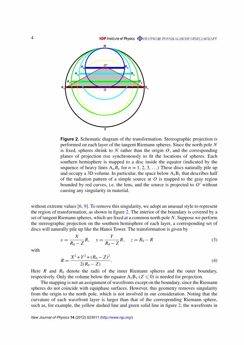
Figure 2. Schematic diagram of the transformation. Stereographic projection isperformed on each layer of the tangent Riemann spheres. Since the north pole Nis fixed, spheres shrink to N rather than the origin O , and the correspondingplanes of projection rise synchronously to fit the locations of spheres. Eachsouthern hemisphere is mapped to a disc inside the equator (indicated by thesequence of heavy lines An Bn for n = 1, 2, 3, . . .) These discs naturally pile upand occupy a 3D volume. In particular, the space below A1B1 that describes halfof the radiation pattern of a simple source at O is mapped to the gray regionbounded by red curves, i.e. the lens, and the source is projected to O ′ withoutcausing any singularity in material.
without extreme values [6, 9]. To remove this singularity, we adopt an unusual style to representthe region of transformation, as shown in figure 2. The interior of the boundary is covered by aset of tangent Riemann spheres, which are fixed at a common north pole N . Suppose we performthe stereographic projection on the southern hemisphere of each layer, a corresponding set ofdiscs will naturally pile up like the Hanoi Tower. The transformation is given by
x =X
R0 − ZR, y =
Y
R0 − ZR, z = R0 − R (3)
with
R =X 2 + Y 2 + (R0 − Z)2
2(R0 − Z). (4)
Here R and R0 denote the radii of the inner Riemann spheres and the outer boundary,respectively. Only the volume below the equator A1B1 (Z 6 0) is needed for projection.
The mapping is not an assignment of wavefronts except on the boundary, since the Riemannspheres do not coincide with equiphase surfaces. However, this geometry removes singularityfrom the origin to the north pole, which is not involved in our consideration. Noting that thecurvature of each wavefront layer is larger than that of the corresponding Riemann sphere,such as, for example, the yellow dashed line and green solid line in figure 2, the wavefronts in
New Journal of Physics 14 (2012) 023011 (http://www.njp.org/)
5
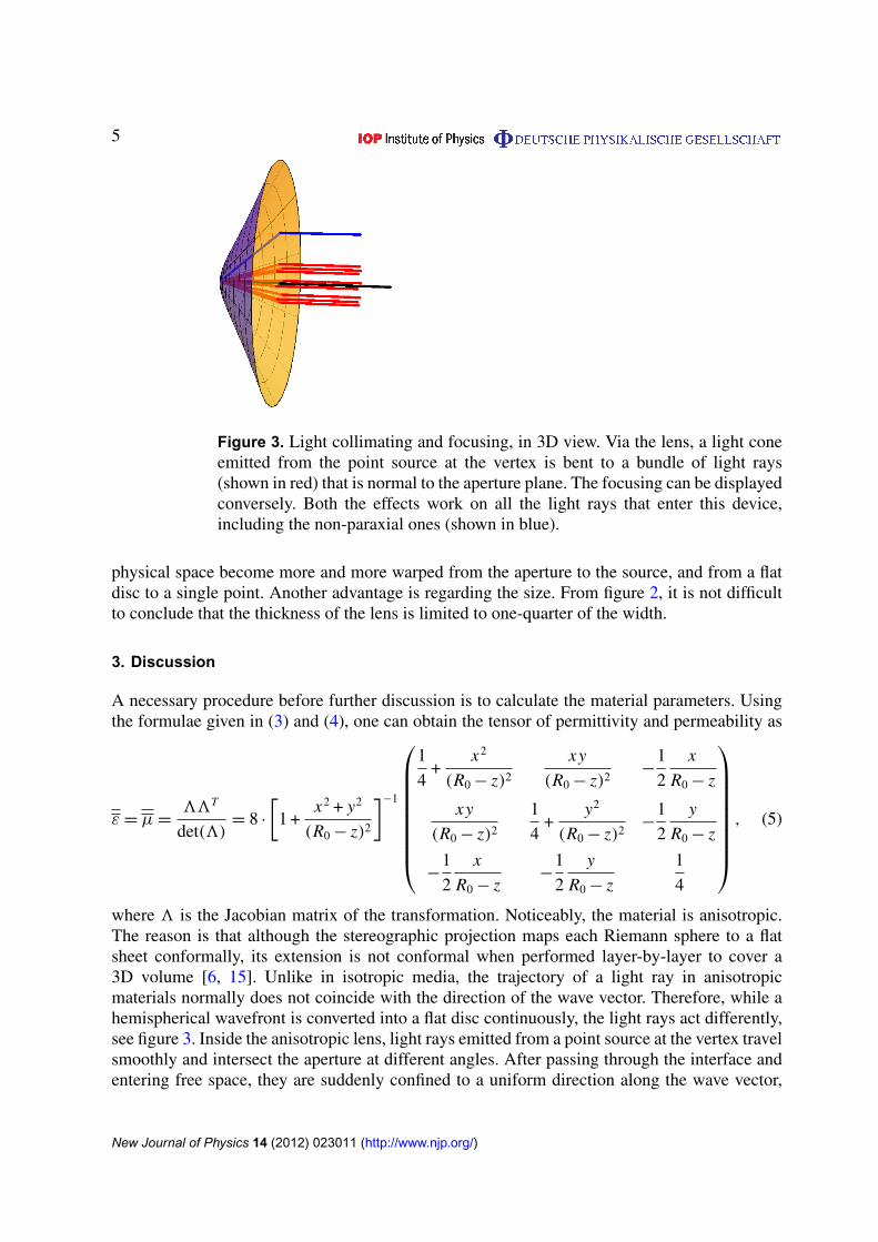
Figure 3. Light collimating and focusing, in 3D view. Via the lens, a light coneemitted from the point source at the vertex is bent to a bundle of light rays(shown in red) that is normal to the aperture plane. The focusing can be displayedconversely. Both the effects work on all the light rays that enter this device,including the non-paraxial ones (shown in blue).
physical space become more and more warped from the aperture to the source, and from a flatdisc to a single point. Another advantage is regarding the size. From figure 2, it is not difficultto conclude that the thickness of the lens is limited to one-quarter of the width.
3. Discussion
A necessary procedure before further discussion is to calculate the material parameters. Usingthe formulae given in (3) and (4), one can obtain the tensor of permittivity and permeability as
ε = µ =33T
det(3)= 8 ·
[1 +
x2 + y2
(R0 − z)2
]−1
1
4+
x2
(R0 − z)2
xy
(R0 − z)2−
1
2
x
R0 − z
xy
(R0 − z)2
1
4+
y2
(R0 − z)2−
1
2
y
R0 − z
−1
2
x
R0 − z−
1
2
y
R0 − z
1
4
, (5)
where 3 is the Jacobian matrix of the transformation. Noticeably, the material is anisotropic.The reason is that although the stereographic projection maps each Riemann sphere to a flatsheet conformally, its extension is not conformal when performed layer-by-layer to cover a3D volume [6, 15]. Unlike in isotropic media, the trajectory of a light ray in anisotropicmaterials normally does not coincide with the direction of the wave vector. Therefore, while ahemispherical wavefront is converted into a flat disc continuously, the light rays act differently,see figure 3. Inside the anisotropic lens, light rays emitted from a point source at the vertex travelsmoothly and intersect the aperture at different angles. After passing through the interface andentering free space, they are suddenly confined to a uniform direction along the wave vector,
New Journal of Physics 14 (2012) 023011 (http://www.njp.org/)
6
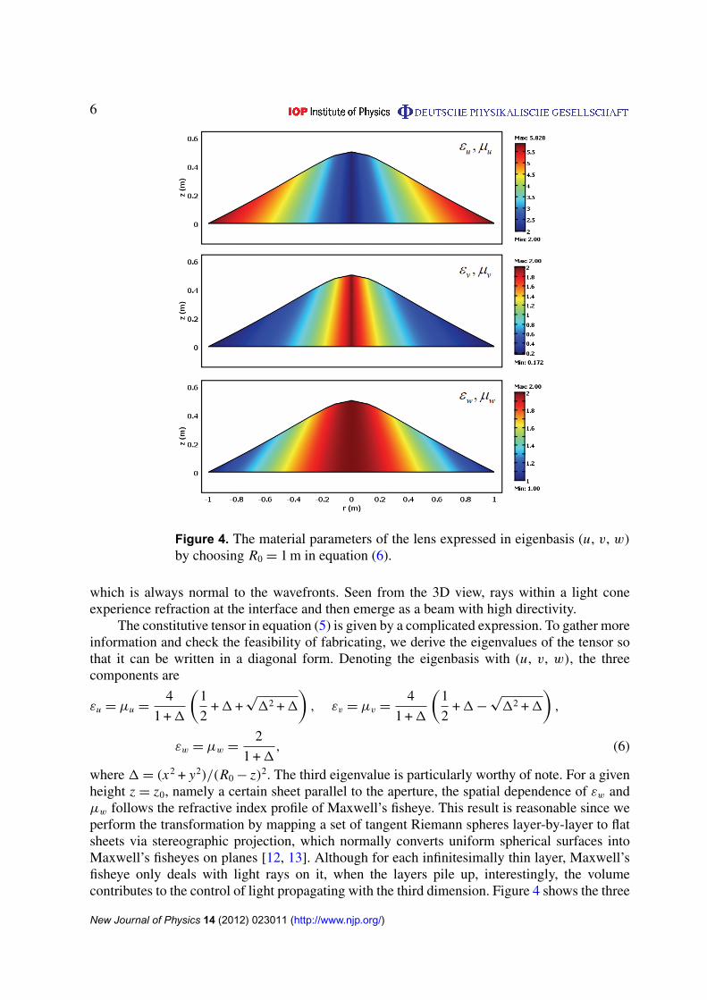
Figure 4. The material parameters of the lens expressed in eigenbasis (u, v, w)
by choosing R0 = 1 m in equation (6).
which is always normal to the wavefronts. Seen from the 3D view, rays within a light coneexperience refraction at the interface and then emerge as a beam with high directivity.
The constitutive tensor in equation (5) is given by a complicated expression. To gather moreinformation and check the feasibility of fabricating, we derive the eigenvalues of the tensor sothat it can be written in a diagonal form. Denoting the eigenbasis with (u, v, w), the threecomponents are
εu = µu =4
1 + 1
(1
2+ 1 +
√
12 + 1
), εv = µv =
4
1 + 1
(1
2+ 1 −
√
12 + 1
),
εw = µw =2
1 + 1, (6)
where 1 = (x2 + y2)/(R0 − z)2. The third eigenvalue is particularly worthy of note. For a givenheight z = z0, namely a certain sheet parallel to the aperture, the spatial dependence of εw andµw follows the refractive index profile of Maxwell’s fisheye. This result is reasonable since weperform the transformation by mapping a set of tangent Riemann spheres layer-by-layer to flatsheets via stereographic projection, which normally converts uniform spherical surfaces intoMaxwell’s fisheyes on planes [12, 13]. Although for each infinitesimally thin layer, Maxwell’sfisheye only deals with light rays on it, when the layers pile up, interestingly, the volumecontributes to the control of light propagating with the third dimension. Figure 4 shows the three
New Journal of Physics 14 (2012) 023011 (http://www.njp.org/)

7
Figure 5. Electric field distribution due to a line current source located at thevertex of the 2D lens at (a) 2.5 GHz and (b) 6.5 GHz. The power flow lines (ingray) as well as the equiphase contours show how light rays and wavefrontspropagate, respectively.
eigenvalues in cross-section. As seen, εw and µw range from 1 to 2 and vary as Maxwell’s fisheyedoes on each horizontal layer, where the minimum value is tailored by the height-dependentoutline. Meanwhile, as a result of avoiding the singular point in transformation, the other twoeigenvalues are also limited in a finite range.
The formula in equation (3) leads to a 3D device; however, sharing the same geometryin cross section, one can repeat a similar procedure in 2D space, in which the stereographicprojection conformally maps a circle into a line. In this case, the lens acts as a cylindrical-to-plane-wave converter [8]. We omit the detailed derivation and presentation of materialparameters here, but directly show the numerical results. In simulations, a line current source islocated slightly inside the vertex, and the outline is covered by a perfect electric conductor (PEC)shell to confine the radiation. Figure 5 gives the electric field distribution at 2.5 and 6.5 GHz.The different behaviors of wavefronts and light rays (denoted by power flow lines in gray) canbe observed in both cases: the wavefronts are converted gradually and smoothly, while the lightrays suffer refraction at the interface. After leaving the aperture, light rays coincide well withthe normal direction of wavefronts, which means a high-directive emission.
At last, we would like to discuss the possibility of further reducing the thickness of thelens. This question is equivalent to achieving a larger width-to-thickness ratio. Actually, thefactor is determined by the geometrical representation of the virtual space; see figure 6(a) forinstance. The space is still presented by a set of tangent spheres. Using a different definitionof stereographic projection that settles the plane at the south pole, one can obtain a widerlens (in red) compared with the original scheme (in blue). But unfortunately, the translationof the projected plane is a linear operation; thus the thickness and width are enlarged in thesame scale. To mainly squeeze the thickness, we need to change the manner of describing thespace. Figure 6(b) shows an alternative style with bipolar coordinates. Composing an orthogonal
New Journal of Physics 14 (2012) 023011 (http://www.njp.org/)

8
Figure 6. Lens flattening. (a) The translation of planes in the definition ofstereographic projection leads to lenses in different scales, but the geometryis not changed. (b) By using bipolar coordinates to describe the virtual space,we can adjust the ratio of width to thickness. With red circles intersecting atthe two foci, the lens is thicker than the original design in figure 2, since thecircle through source O1 is larger than the one tangent at the north pole andis therefore mapped to a higher position O ′
1. Conversely, if we choose the bluecircles surrounding the foci, the resulting lens will be thinner.
coordinate system, the curved axes, which illustrate four sets of circles, can cover the entireplane completely. Furthermore, one can rotate bipolar coordinates about the y-axis or x-axisto present the 3D space with sets of spheres in toroidal coordinates or bispherical coordinates.Both options are available to perform the layer-by-layer transformation like equation (3), butnoting the difference in how the spheres intersect, only the bispherical coordinates can be usedto obtain a thinner lens. Putting it in a mathematical form, we have
x = a · coth τ, y =Y
1 −X − a · coth τ
a/ sinh τ
, z =Z
1 −X − a · coth τ
a/ sinh τ
(7)
with
(X − a · coth τ)2 + Y 2 + Z 2= a2/ sinh2 τ, (8)
where a denotes the foci and τ is the variable in bispherical coordinates describing the positionand radius of each sphere. Compared with figure 2, the scenario here can make the lens very thinin theory. The cost of this improvement is that the derivation will be much more complicated, asthe spheres do not share a common north pole for projection and the maximum and minimumof the first two eigenvalues will increase and decrease, respectively (but still finite), while thethird eigenvalue keeps its spatial dependence like Maxwell’s fisheye.
4. Conclusion
In summary, we present a scheme to design a thin lens that converts spherical waves intoa collimated beam. The lens is made of transformation media. By performing stereographic
New Journal of Physics 14 (2012) 023011 (http://www.njp.org/)
9
projection layer-by-layer to a set of tangent Riemann spheres, the transformation avoidssingular points; hence the material parameters vary in a finite range. Both the light-ray modeland numerical results show good performance on the directivity of emission. The possibleimprovement in thickness is discussed by changing the representation of the space, and moreinteresting devices could be expected by performing different operations on the layer-by-layergeometries.
Acknowledgments
This work was supported by the National Natural Science Foundation of China (grant numbers11004147, 60877067 and 11174309), the Natural Science Foundation of Jiangsu Province (grantnumber BK2010211) and the Priority Academic Program Development (PAPD) of JiangsuHigher Education Institutions.
References
[1] Pendry J B 2000 Negative refraction makes a perfect lens Phys. Rev. Lett. 85 3966–9[2] Enoch S, Tayeb G, Sabouroux P, Guerin N and Vincent P 2002 A metamaterial for directive emission Phys.
Rev. Lett. 89 213902[3] Leonhardt U 2006 Optical conformal mapping Science 312 1777–80[4] Pendry J B, Schurig D and Smith D R 2006 Controlling electromagnetic fields Science 312 1780–2[5] Chen H Y, Chan C T and Sheng P 2010 Transformation optics and metamaterials Nature Mater. 9 387–96[6] Leonhardt U and Tyc T 2008 Superantenna made of transformation media New J. Phys. 10 115026[7] Kwon D-H and Werner D H 2008 Transformation optical designs for wave collimators, flat lenses and right-
angle bends New J. Phys. 10 115023[8] Jiang W X, Cui T J, Ma H F, Zhou X Y and Cheng Q 2008 Cylindrical-to-plane-wave conversion via
embedded optical transformation Appl. Phys. Lett. 92 261903[9] Zhang J, Luo Y, Chen H and Wu B-I 2008 Manipulating the directivity of antennas with metamaterial Opt.
Express 16 10962–7Tichit P-H, Burokur S N and Lustrac A de 2009 Ultradirective antenna via transformation optics J. Appl.
Phys. 105 104912[10] Schmiele M, Varma V S, Rockstuhl C and Lederer F 2010 Designing optical elements from isotropic materials
by using transformation optics Phys. Rev. A 81 033837[11] Yao K and Jiang X 2011 Designing feasible optical devices via conformal mapping J. Opt. Soc. Am. B
28 1037–42[12] Luneburg R K 1964 Mathematical Theory of Optics (Berkeley, CA: University of California Press)[13] Leonhardt U 2009 Perfect imaging without negative refraction New J. Phys. 11 093040[14] Leonhardt U and Tyc T 2008 Broadband invisibility by non-Euclidean cloaking (supplementary data) Science
323 110–2[15] Minano J C, Benıtez P and Gonzalez J C 2010 Perfect imaging with geodesic waveguides New J. Phys.
12 123023
New Journal of Physics 14 (2012) 023011 (http://www.njp.org/)