COLLEGE OF ARCHITECTURE AND ENGINEERING...
58
1 UNIVERSITY OF NAIROBI COLLEGE OF ARCHITECTURE AND ENGINEERING DEPARTMENT OF MECHANICAL AND MANUFACTURING ENGINEERING PROJECT TITLE: DEVELOPMENT OF A REMOTE CONTROLLED AERIAL VEHICLE (RVAV) FOR DELIVERY OF EMMERGENCY AID PROJECT CODE NO: JMO 05/2016 AUTHORS: ATONYA SHELDON INDANYA – F18/39745/2011 IRERI IAN NDAMBIRI – F18/39995/2011 SURPERVISOR: PROF. JULIUS OGOLA
Transcript of COLLEGE OF ARCHITECTURE AND ENGINEERING...

1
UNIVERSITY OF NAIROBI
COLLEGE OF ARCHITECTURE AND ENGINEERING
DEPARTMENT OF MECHANICAL AND MANUFACTURING
ENGINEERING
PROJECT TITLE:
DEVELOPMENT OF A REMOTE CONTROLLED AERIAL VEHICLE
(RVAV) FOR DELIVERY OF EMMERGENCY AID
PROJECT CODE NO:
JMO 05/2016
AUTHORS:
ATONYA SHELDON INDANYA – F18/39745/2011
IRERI IAN NDAMBIRI – F18/39995/2011
SURPERVISOR:
PROF. JULIUS OGOLA

ii
DECLARATION
We declare that this is our original work and has not been presented in this university or other
university for examination or other purpose.
IAN IRERI F18/39995/2011
Signature ……………………….
Date…………………………….
SHELDON INDANYA F18/39745/ /2011
Signature………………………..
Date…………………………….
This project has been submitted for examination with approval as university supervisor.
Prof. JULIUS OGOLA
Signature………………………….
Date………………………………..
iii
ACKNOWLEDGEMENT
We would like to express our gratitude to Prof. Julius Ogola for his continued support and
encouragement. He kept us focused and determined and we offer our sincere appreciation for
the learning opportunity and amazing experience.
We would also like to acknowledge the support and assistance of the University of Nairobi,
Science and Technology Park-Fab Lab Nairobi and Gearbox Company. The support from
Fablab and Gearbox staff was vital. Special Thanks to Mr. Derrick Mugasia of Fablab, Dr.
Gachigi and Mr. Ken of Gearbox for their constant guidance and technical support.
The completion of this project could not have been possible without the support of our
parents, friends and families. Their encouragement and assistance was invaluable. They were
and always will be our source of strength. Our heart-felt gratitude goes out to them.

iv
ABSTRACT
The aim of the project was to develop a low-cost Remote Controlled Aerial Vehicle (RVAV)
for delivery of emergency aid. This report therefore gives design of the quadrotor,
comprising its architecture and control. Theoretic formulae and parameters guided the design
of the quadrotor model as they dictated the starting point of the design .This process of
designing the aerial vehicle involved designing the frame using Solidworks, then fabricating
the frame designs using laser cutter. The frame parts were joined together using nuts and
bolts. The propellers were mounted on the motor which were fixed on the frame using
screws. Thin rubber was used to damp vibrations from the motor to the arm. Electrical
components such as control board receivers and connectors were connected as per the circuit
design. This demonstrates the ability to build non-commercial, competitive academic
platforms for control education through flying vehicles.
The quadrotor model design was simulated in flow conditions using Solidworks to determine
its performance characteristics and consequently conclude the same for the actual prototype
based on the principle of dimensional analysis and similarity. Finite Element Analysis (FEA)
was also done using Solidworks 2014 to determine safety factor of the material and the
behaviour of the model on flight.
From the test it was concluded the acrylic material was suitable since it is light in weight and
strong with low bending vibrations. The shaped design experienced less drag therefore
having little effect on the speed of the aerial vehicle. We noted that in fabricating propellers,
it would be difficult to obtain smooth surface finish therefore we opted to purchase them.

v
TABLE OF CONTENTS CHAPTER ONE ......................................................................................................................................... 1
INTRODUCTION ...................................................................................................................................... 1
1.1: INTRODUCTION ....................................................................................................................... 1
1.2: PROBLEM STATEMENT .......................................................................................................... 2
1.3: OBJECTIVES .............................................................................................................................. 2
CHAPTER TWO ........................................................................................................................................ 3
RESEARCH METHODOLOGY ................................................................................................................... 3
CHAPTER THREE ...................................................................................................................................... 4
LITERATURE REVIEW .............................................................................................................................. 4
3.1: QUADROTOR: PRINCIPLE OF OPERATION ........................................................................ 4
CHAPTER FOUR ....................................................................................................................................... 8
RESEARCH FINDINGS .............................................................................................................................. 8
4.1: DESIGN OF THE QUADCOPTER ..................................................................................................... 8
4.1.1: Flight Control Unit ................................................................................................................ 9
4.1.2: Brushless DC motors .......................................................................................................... 10
4.1.3: Battery ................................................................................................................................. 11
4.1.4: Propellers ............................................................................................................................ 12
4.1.5: Frame .................................................................................................................................. 15
4.2: FRAME PRODUCTION AND QUADCOPTER ASSEMBLY ............................................... 30
4.2.1: Component parts of a Quadrotor. ........................................................................................ 30
4.2.2: Cutting out the Frame ........................................................................................................ 30
4.2.3: Assembling Frame ............................................................................................................. 31
4.2.4: Fixing motors. ..................................................................................................................... 31
4.2.5: Assembling electronics ....................................................................................................... 31
4.2.6: Testing the Flight Control Board ........................................................................................ 32
4.2.7: Calibration of Electronic Speed Controllers ....................................................................... 32
4.2.8: Arming the motors .............................................................................................................. 32
4.3: MODEL PERFORMANCE CHARACTERISTICS ................................................................. 33
4.4 COMPUTER SIMULATION ..................................................................................................... 34
STRESS ANALYSIS OF THE FRAME ...................................................................................... 34
STRESS ANALYSIS OF THE ARM REPORT .......................................................................... 38
STRESS ANALYSIS OF THE STAND REPORT ...................................................................... 42
CHAPTER FIVE ....................................................................................................................................... 46

vi
CONCLUSION AND RECOMMENDATIONS ........................................................................................... 46
5.1: Discussion .................................................................................................................................. 46
5.2: Conclusion ................................................................................................................................. 46
5.3: Recommendations ...................................................................................................................... 46
5.4: References .................................................................................................................................. 47
APPENDIX ................................................................................................................................... 49
List of Figures Figure 2 ................................................................................................................................................... 5
Figure 1 ................................................................................................................................................... 4
Figure 3 ................................................................................................................................................... 5
Figure 4 ................................................................................................................................................... 6
Figure 5 ................................................................................................................................................. 10
Figure 6 ................................................................................................................................................. 10
Figure 7 ................................................................................................................................................. 14
Figure 8 ................................................................................................................................................. 14
Figure 9 ................................................................................................................................................. 17
Figure 10 ............................................................................................................................................... 18
Figure 11 ............................................................................................................................................... 19
Figure 12 ............................................................................................................................................... 20
Figure 13 ............................................................................................................................................... 21
Figure 14 ............................................................................................................................................... 22
Figure 15 ............................................................................................................................................... 23
Figure 16 ............................................................................................................................................... 24
Figure 17 ............................................................................................................................................... 28
Figure 18 ............................................................................................................................................... 29
Figure 19 ............................................................................................................................................... 30

vii
LIST OF SYMBOLS
Variable Description Unit
Natural frequency Radians/sec
Modes of frequency
Ρ Density kg/m3
A Area m2
E Modulus of Elasticity N/m2
or Pa
I Second moment of inertia m4
.
Yield Strength N/m2
or Pa
Natural frequency Hz
Von mises yield criterion MPa
Yield stress of the material in pure shear N/m2
or Pa
V Voltage Volts
F Propellers’ thrust N
Change in pressure

viii
APPENDIX
APM Planner User Interface

ix
LIST OF ABBREVIATIONS
ESCs- Electronic Speed Controllers
FC- Flight Controller
FEA-Finite element analysis
Gpa-Giga Pascals
IMU- Inertial Measurement Unit
Mpa-Mega Pascals
PMMA- polymethyl methacrylate
RCAV- Remote Controlled Aerial Vehicle
TV- Television
UAV- Unmanned aerial vehicles
WHO- World Health Organization

1
CHAPTER ONE
INTRODUCTION
1.1: INTRODUCTION A quad copter is a form of aircraft that flies by use of four rotors. Aircraft is any machine that
is capable of flight in air either due to buoyancy or dynamic action of air on its surface.
Aircraft can be classified according to design, method of lift, and propulsion and also size of
aircraft. The more common and general mode of classifying them is by their means of lift and
propulsion. Under this, aircraft are divided into two main categories:
Aerostats – these are aircraft that use buoyancy to float in air. Examples include air
balloons that use low density gases like helium, kites and airships.
Aerodynes – these aircraft are heavier than air and they use aerodynamic and powered
lift in form of engine thrust.
Aerodynes can be further classified into three:
1. Flexible wing aircraft – they have their wings made of fabric or thin sheet of material
fixed on a rigid frame.
2. Fixed wing aircraft – they use rigid wings to provide aerodynamic lift.
In both of these cases, the wings are shaped like aerofoils to keep the craft airborne by
forward movement of the wings.
3. Rotorcraft – these aircraft use wing shaped rotors to provide lift and propulsion. A
number of rotor blades are mounted onto a single mast which is made to rotate.
A quad copter is a multirotor flying object that employs use of four rotors for lift.
They use two pairs of identically fixed pitched propellers, one clockwise and the
other, anticlockwise.
The purpose of this project is to form a basis for further development of quadcopter design,
analysis, development and control. The project covers many aspects of mechanical
engineering, which include engineering design in form of calculations and computer
simulation of the quadcopter frame, mechanical vibration analysis of the arms to stabilise its
dynamics, fluid mechanics to analyse drag effects and aerial performance of the aircraft. All
the materials used were locally sourced thus it is much easier, faster and cheaper to develop a
quadcopter.

2
1.2: PROBLEM STATEMENT A lot of progress has been made in the field of unmanned aerial vehicles, but effective control
proved to be a major challenge. The aim of this research project will be to produce a
quadcopter model that can be used for future study of mechanics, mechatronics and control of
unmanned remotely piloted aircraft
Delivery of emergency aid to victims during catastrophes, disasters and conflicts has proved
to be difficult, especially in areas that are difficult to access. This leads to the realisation that
use of unmanned flying robots is very important in rescue missions. They can be used to
deliver aid and offer surveillance in areas that are unsafe to reach. Our country has
experienced catastrophes in the past, where delivery of aid on time has been a problem. In
2015, a number of places in Kenya were affected by flooding during El Niño rains. Similarly,
in 2013, we experienced severe flooding in Tana River due to heavy rains. Many people were
affected and there was desperate need for help, but the floods destroyed the available means
of transport (road), making it hard to reach the affected population. Our project aims to
ensure quick delivery of emergency supplies to the affected areas on time, working in co-
operation with humanitarian organisations and the government.
As a continuing project, the previous group was able to develop and fabricate a quadcopter,
but it was unable to achieve flight. Our main objective in this project is to create an aerial
vehicle that is capable of achieving lift.
1.3: OBJECTIVES 1) To design and construct a model of a remotely controlled aerial vehicle for delivering
emergency aid.
2) To test the model to determine its performance characteristics.
3) Develop a computer simulation of its performance in actual use.

3
CHAPTER TWO
RESEARCH METHODOLOGY
In order to fulfil the objectives previously described, a clear sequence of tasks had to be
carried out. A complete description of the work undertaken was organised into sections as
follows.
First of all, an extensive work of research was done in order to fulfil the first of the
objectives, which was to acquire a basic understanding about the characteristics of quadrotor
machines. This research gave a considerable importance to the resources available on the
Internet, since the traditional resources (books, articles…) contained detailed information
about specific subjects (control techniques, dynamic models…).
The research encompassed a wide range of resources including studies done at different
universities and hobby enthusiast’s sources, our project supervisor and other students
interested. The research included the aerodynamic of quadrotors, theory and principle of each
quad component.
Apart from literature research we went to the field to research on the availability of the
materials required in making our quadrotor and their prices. We also got information from
friends who have different skills in the areas that we needed in our project.
The next step was the task of building the physical model of the quadrotor. This meant
writing down the equations of motion and the equations of the motors. As for the rotor model,
several options were examined.
Experimental data was needed to adjust several parameters and to validate the model itself. In
order to obtain these experimental data a complete sequence of tests with the quadrotor were
carried out. These tests proved successful, providing data about the characteristics of drag of
the whole prototype while on flight. Another task was to obtain the stress analysis of the
whole model. A complete AutoCAD and Solidworks software model of the quadrotor was
made.
Once the physical model was ready, it was possible to build the Simulation model of the
quadrotor. Finally, potential control problems were identified, previously known results were
confirmed and new flight characteristics were observed.

4
CHAPTER THREE
LITERATURE REVIEW
3.1: QUADROTOR: PRINCIPLE OF OPERATION
A quadrotor uses 4 rotors to create thrust to lift the aircraft. Two opposite facing rotors are
made to rotate clockwise, while the other pair rotates counter clockwise. This configuration
balances out the torque generated by the individual motors. A quadrotor has 4 controllable
movements: yaw, roll, pitch & altitude. These can be achieved by varying thrusts of
individual motors. Hovering is experienced when thrust to each motor is equal to ¼ of the
quadrotor’s total weight, with no rotating moment present.
VISUAL REPRESENTATION OF THE HOVERING POSITION
Increase/Decrease in altitude is achieved by increasing or decreasing thrust from each motor
by the same amount, such that total thrust changes but total torque remains zero.
REPRESENTATION OF ASCENDING (LEFT) AND DESCENDING (RIGHT)
FIGURE 1

5
FIGURE 2
Controlling it manually is impossible and is thus controlled electronically. Each of the motors
is connected to an electronic speed control (ESC). These ESC’s are connected to a central
flight controller board, which is part of a system that uses a microcontroller to control the
quadcopter. It takes input from the user by a RC radio receiver, and also from an
accelerometer and gyroscopic sensor in the control board. It outputs electrical signals to the
ESC’s, which regulate speed of the motors.
Pitch – this is forward or backward movement. It can also be described as swaying of
craft around an axis perpendicular to the direction of motion. This is achieved by
decreasing/increasing front propeller speed with respect to the rear one while the
lateral rotors have equal speeds. The rotational speed variations affect the torque,
making the quadrotor advance or regress.
Roll – this is achieved by increasing/decreasing speed of the left/right rotor with
respect to the right or left one respectively, while the front and rear rotors have equal
speed. A torque is created due to this differential thrust, making the quadrotor tilt and
move left or right.
REPRESENTATION FOR PITCH AND ROLL
FIGURE 3

6
Yaw – when one pair of opposite facing rotors provides more thrust relative to the
other, a torque imbalance occurs making the quadcopter twist about the vertical axis
while maintaining total thrust to maintain altitude.
REPRESENTATION OF YAW MOTION
FIGURE 4
To roll/pitch, one rotor’s thrust is decreased while the opposite rotor’s thrust is increased by a
similar amount. When the quadrotor tilts, the force vector is split into vertical and horizontal
components. This brings about two things: 1st, the copter will move opposite to the direction
of the newly created horizontal component. 2nd
, because the force vector is split, the vertical
component reduces and the copter starts to lose altitude. In view of this, thrust of all rotors is
increased to compensate.

7
REPRESENTATION OF MAIN THRUST, ROLL ANGLE, PITCH ANGLE AND YAW ANGLE
FIGURE 5

8
CHAPTER FOUR
RESEARCH FINDINGS
4.1: DESIGN OF THE QUADCOPTER
As a continuing project, we studied the previous project report and model in order to know
the changes in design and components we had to make for our model to achieve flight .Upon
consultation with the students who had done that project, we decided to make the following
changes:
1. We decided to use a larger battery with a higher capacity and voltage in order to increase
the unmanned aerial vehicle flight time.
2.We used bigger propellers in order to increase the swept volume which in turn increases
the lift .Instead of fabricating as the previous group had done we decided to purchase them.
This is because propellers require a very smooth finish and the available means of fabrication
make it very hard to achieve this.
3 .The motors also had to be changed in favour of ones with a higher power rating this would
improve lift.
4. We also redesigned the frame to reduce the excess mass, which would increase the amount
of load to be carried and make it more aerodynamic. That is, there would be a decrease in
drag.
In designing our frame we first had to put into consideration the size of the electrical
components to ensure they fit properly on the frame. We first began with looking for the
available electrical components.
Upon searching around town, on the internet and asking around, we decided to buy locally
available parts over imports because of the extra costs, regulations and time/shipping
considerations. We were able to obtain the following components:
1. Ardupilot mega 2.6 flight control board.
This flight controller runs on open source software and has a downloadable mission
planner. It contains a 3-axis gyro, an accelerometer, magnetometer, barometer; 4mb
data flash chip for automatic data-logging and an ATMEGA 2560 chip for processing
and ATMEGA 32 U-2 chip for USB capability.
2. Aeolus series 2208 brushless motors (920kv) with 30 ampere electronic speed control
(ESC).

9
This type of motor generates thrusts of between 400-900 grams, weighing 49.5g, high
efficiency, high load capacity and long service life. No load current of 0.3A.
3. 10*4.5” plastic propellers.
4. Turnigy radio control 9*9 channel transmitter with module and 8 channel receiver
(2.4GHz).
5. 14.8V 5500mAh LiPo battery with 4 cells and 50C-rating.
6. Voltage regulator for 5 Volts.
7. Power distribution board.
Total mass of electrical components = 1106 grams
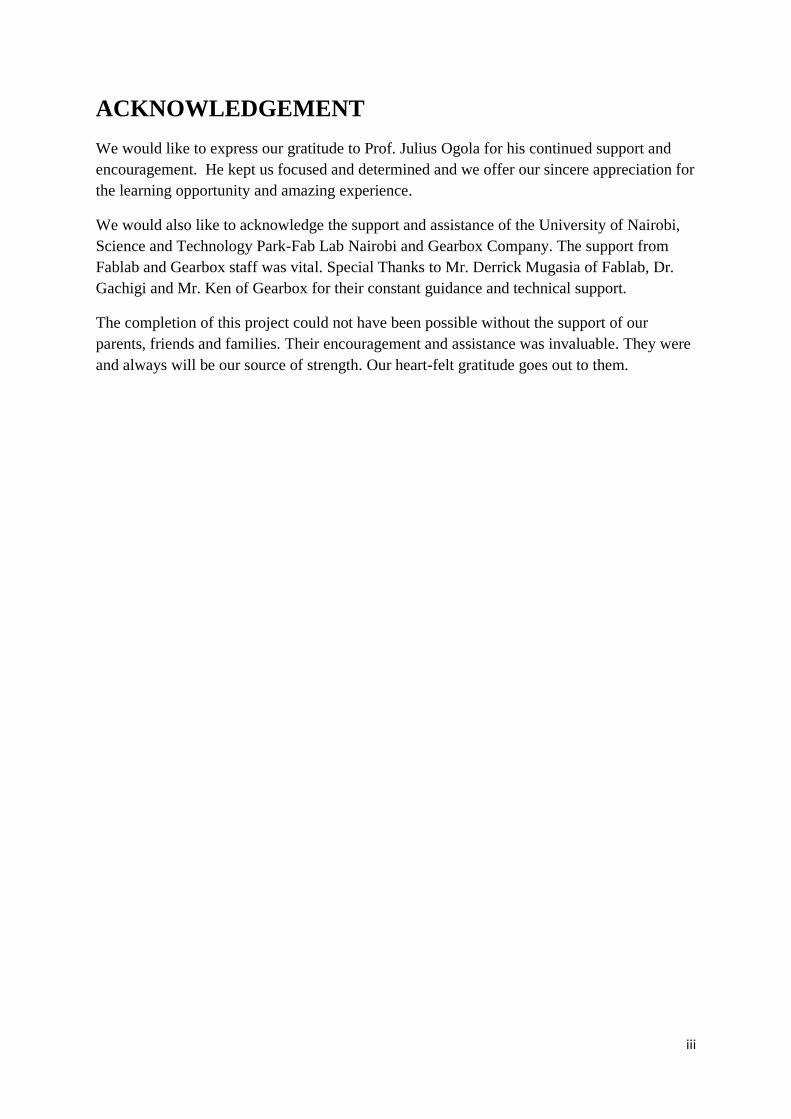
4.1.1: Flight Control Unit Achieving effective control of a quadcopter by mechanical means is very difficult and
therefore an electric system containing a microcontroller is used to achieve stable flight. This
system also consists of an accelerometer and gyroscope to aid in positioning itself. The
combination of these makes up the flight control board.
Initially we had considered making our flight control board by ourselves but to save time and
cost, purchasing one was the viable option. These boards are very compact; they contain high
accuracy components, are up to date and are readily available. We obtained an Ardupilot
Mega 2.6 Board with side entry. This board runs on open source software thus is easily
programmable. It contains the following components:
A 3-axis gyroscope (roll, pitch and yaw)
Accelerometer. This instrument simply measures acceleration forces.
Magnetometer. This is an instrument that detects fluctuations in the earth’s magnetic
field
Barometer for measuring ambient pressure
4 mega-byte data flash chip for automatic data-logging from the radio receiver (Rx)
Two microcontrollers; an ATMEGA 2560 chip for processing and an ATMEGA 32U-
2 chip for USB purpose.
The data that is input into the controller is processed and is output as electric signals sent to
electronic speed controllers (ESC) attached to the motors. These ESC’s convert the electrical
signals into rotational motion of the motor. Thus, flight can therefore be achieved by
controlling the motion of all the motors.
10
FIGURE 5
FIGURE 6
4.1.2: Brushless DC motors
Direct current (DC) motors rely on the action of electromagnetic forces to convert electric
power in form of DC current into mechanical movement mainly through a shaft. A brushless
motor is basically a DC motor, but with a few modifications. In a conventional DC motor, a
brush is used to alternate the direct current to enable continuous movement of the armature.
This arrangement has a bottleneck in that sparks appear when the brush comes in contact with
the current carrying wires. Also this contact is associated with friction and thus the longevity
of such motors is limited. One of the modifications made in a brushless motor is that this

11
brush is replaced by an electronic speed controller which alternates and controls the current
going to the motor. This improves efficiency and life of the motor considerably.
Brushless motors are lighter than brushed ones for the same power output. We used Aeolus
series 2208-920Kv motor weighing 49.5g. For multi-rotor application, 600-1200kV motors
are good. Below 600kV is even better because low kV can swing big propellers, meaning it
can move more air and you will get more thrust, at the cost of higher current.
Kilo Volts = RPM/V
With 920kV motor and 14.8 V battery to supply power, the RPM of each motor at no load
will be;
920 x 14.8 = 13616 RPM
To lift a quadrotor of 1600 grams, we need a total 3200grams of thrust that is twice the
weight of the quadrotor. For 4 motors,
Thrust per motor = (Weight x 2) / 4
3200g / 4 = 800 grams
Power (Watts) = V (Voltage) x I (Ampere)
4.1.3: Battery
We decided to use LiPo batteries since they have a high capacity to weight ratio. As a
continuing project, a relatively stronger battery was used. We installed a 5500mAh capacity
battery of 14.8 volts consisting of four cells. It had a C-rating of 50C. A C-rating is a measure
of the maximum amount of current that can be drawn from the battery at a given time. For
our case,
Maximum current = capacity*C-rating
= 5500mAh*50C = 275 Amperes
This high current is regulated with aid of the electronic speed controllers and the voltage was
also stepped down using a voltage regulator. This voltage regulator was especially used
because the flight control board runs at 5 volts compared to the battery which is at 14.8 volts.
Maximum possible current draw from battery = 50C * 5500mAh = 275A
Maximum possible power draw from battery = V*I = 14.8* 275 = 4070 W
Watt-hour (W.hr) is the power available from a cell for a given time
= Volts * ampere-hours
=14.8V * 5.5Ah = 81.4 W.hr

12
Therefore, battery duration at maximum power draw
= 81.4 W.hr/4070 W = 0.02 hr = 1.2 minutes
The battery provides 5.5 amperes in 1 hour. Similarly, it provides double the current for half
the time, i.e. 11A in 30 minutes, 16.5A in 20 minutes, and 22A in 15 minutes. The limit of
the electronic speed control is 30A, so at this maximum current, the battery will last
approximately 11 minutes.
Flight time = battery capacity (A.hr)/average current (A) * 60
4.1.4: Propellers
Propellers work by using Newton’s Third Law of motion and the principles of lift. The
propeller exerts a force on the air as it passes through, which accelerates the air. Newton’s
Third Law states that a reaction must take place, which pushes the propeller, and in turn the
craft, forward. Additionally, the blades of the propeller are not flat, but have an airfoil shape
to them in order to more effectively push the air. This works on the same principle as an
airplane wing: a pressure differential between each side of the airfoil produces a force that
pushes the propeller (and therefore the craft) forward. These two effects working together
produce the thrust necessary to make planes and helicopters fly.
4.1.4.1: Basic Equations of a propeller
The thrust a propeller generates can be measured in multiple ways. The most effective way is
to use a test stand to quantitatively measure the thrust, but this can be time consuming and
requires additional physical components (the test stand). An alternative to actually measuring
the thrust is to analytically calculate an estimation of the thrust, which is achievable through
several methods. The main approaches can be split into two categories: pressure-based and
mass flow-based. The pressure based equation multiplies the sweep area of the propeller and
the change in pressure on each side of the propeller:
F=
Where (d represents downstream of the propeller, and u upstream). The
values for these static pressures can be calculated with the following equation:
Where po is static pressure, ρ is air density, and V is air velocity. The thrust can then be
expressed in terms of the differences in velocity when combined with the first equation:
An alternate method of reaching the same equation involves the use of mass flow rates
instead of pressures. The initial equation uses Newton’s third law and states:

13
In order to continue, we must find the velocity of the air at the propeller, which is assumed to
be the average of each side of the propeller:
From this, it is possible to solve for the mass flow rate; this is then combined with the
previous two equations to get the same equation as when beginning with pressure terms:
However, if velocity terms are not easily measurable, an alternate method for calculating
accurate thrust of a propeller.
F = (1.1013 * 10-6
) (9202)
F = 0.93214 kg
The above equation, relating RPM to kilograms of thrust, can be used in simulations of the
quadrotor. Even though it is an estimate, it matches the actual measured data closely enough
within the predicted RPM range for calibration purposes when a calibration coefficient of .34
is added to the equation.
Propellers are classified into two parts the length and the pitch.
Pitch is the distance travelled forward by the propeller per revolution in a perfect medium.

14
FIGURE 7
If the motor runs at 13616 RPM at no load, but you mount the propellers the RPM reduces.
We used propeller specifications of (10*4.5) where the length is 10 inches and the propeller
pitch is 4.5 inches. This means the propeller will travel 4.5 inches so (60×4.5=270 inches per
sec) this means our quad will rise in the air at a rate of 270 inches/sec.
Increased propeller pitch and length draws more current. High pitch means slower rotation
but to increase the speed means using of more power. Low pitch number can generate more
torque and also increase stability. High pitch propellers move greater amount of air then
creates turbulence causing wobbling during hovering. Thus for good quadrotor design, low
pitch propellers are efficient.
FIGURE 8

15
4.1.5: Frame
Material Selection
TABLE 1: MATERIAL SELECTION
Material Modulus of
Elasticity (Gpa)
Tensile Strength
(MPa)
Density (g/cm3)
Nylon 6.6 2.61 82.8 1.14
ABS .001 29.0 1.02
PLA plastic 3.5 50 1.25
Delrin® 2.55 52.4 1.42
Carbon Fiber 220 760 1.7
Stainless Steel 404 200 1790 7.80
Aluminum 7075 71 572 2.80
Acrylic/Perspex 2.5 70 1.19
We decided to choose acrylic for our frame due to a number of reasons, which include:
High strength to weight ratio
It is readily available in form of sheets
Low cost
It is easily machined
High shock, abrasion and flex resistance
Excellent weather and UV resistance
Low density/ light weight compared with metals and glass
Comprehensive range of colours and finishes
100% recyclability
A tensile test of the acrylic material was done in the lab using tensile test machine and it was
found that the yield stress of acrylic to be 70.7 MPa. This test was done because the material
was going to be subjected to loads, and it was important to know that the material is strong
enough and rigid enough to withstand the loads that it will experience in service.

16
TABLE II PROPERTIES OF ACRYLIC
PROPERTIES VALUES
MODULUS OF ELASTICIY 2.5 Gpa
POISSON RATION 0.39
DENSITY 1.19 g/cm3
TENSILE STRENGTH 75 Mpa
4.1.5.1: Frame analysis.
The method used in analysis of the frame include; Vibration frequency analysis on choosing
the size of the frame and Finite element analysis/Stress analysis.
For stable and reliable quadcopter flight, a good quadcopter requires a rigid and optimal
frame. This process begins with choice of frame type. For quadcopters, there are two types of
frames i.e. the X type frame and the + type configuration. The X type has more stability
compared to the + type, but the + configuration has better flight response.
After choosing the frame, we analysed the dimensional requirements.
Let’s assume a simple + frame ABCD as shown on the next page,

17
Since each propeller diameter is approximately 25cm, drawing a line from one corner to the
other, this hypotenuse should be greater than 25cm for the propellers to swing without
coming into contact with each other. In view of this, let this distance be equal to 28cm.
Recall that,
(AB) 2
= (OB) 2+ (OA)
2
But for our copter, OB=OA. Say OA+OB = L
Therefore,
0.282= (2L
2)
0.282/2=L
2
And L= 39cm. Then, OA=OB=0.0196m
Thus, for propellers of length 28cm, the minimum length of distance AB should be 0.0196m.
Distance BD should be 0.0196*2= 0.0392m. This is the distance between two opposite facing
motors.
B
A
C
D
O
25cm
FIGURE 9

18
Design of Arms, Centreplate and Landing Gear
To determine the length of each arm, we must first consider the size of the centreplate. This
centreplate holds most of the electronic components. In its design we had to consider the
longest item which is the battery at 15cm length. This meant that the plate should be around
16cm in length as shown;
0.39- 0.16 = 0.23m
0.23/2 = 0.115m
The distance from the edge of the centreplate to the midpoint of the motor is 0.115m. let us
call this length φ. Since motor diameter is 0.029m, we added 0.015m to the arm length and
an extra 3cm to account for the area where the arm will be joined to the centreplate by use of
B
A
D
C
16cm
16cm
φ
FIGURE 10

19
bolts as shown below;
This gives a minimum total length of 0.16m for the arm.
For arm width, diameter of the motors was considered. They had a diameter of 0.029m and so
chose the width to be 0.03m. The material came in standard sheets of constant thickness of
6mm which is 0.006m.
Total volume of an arm = 0.03*0.16*0.006 = 2.88*10-5
m3
For the four arms, 4* 2.88*10-5
m3 = 1.152*10
-4 m
3
Mass = volume * density = 1.152*10-4
m3* 1188 kg/m
3 = 0.1369kg
For the centreplate to be a square of side 0.16m, it would have considerable unnecessary
weight and would affect aerodynamics of the craft. So we removed some chunks off it as
shown below to minimise air resistance and weight while maintaining enough rigidity to
11.5cm 1.5cm
3cm
Extra length for motor
Extra length for attachment to centreplate
FIGURE 11

20
carry the electronic components.
Total area of centre plate = area of square - ∑areas a to h
A= (0.16)2
– 0.0103 = 0.0153m2
Volume V= 0.0153 * 0.006 = 9.18 * 10
-5m
3
Mass of two centreplates = 2ρV = 2* 1188kg/m3
* 9.18 * 10-5
m3
=0.218kg
For the landing gear, we also used acrylic and were fitted onto the frame using bolts and nuts.
To prevent failure by buckling, we calculated the critical force PCR for each leg.
The mass acting on all legs is given by;
mass of electronics + mass of arms + mass of centreplates
=1.106 + 0.21 + 0.1369 = 1.4529kg
3cm
4.5cm
16cm
5cm
5cm
1.5cm
h
d
c
g
e
b
f
a 5cm
5cm
5cm
5cm
5cm
5cm
16cm
FIGURE 12

21
Since there are four legs, we divide this mass by four to get the mass on each leg;
1.4529/4=0.363225kg
PCR = ((∏2
) EI)/(L2)
= (∏2* 70*10
6 *I)/(L
2)
Assuming the load only acts on area A,
I= (bd3)/12
= 0.02(0.006)3/12 = 3.6 * 10
-10 m
4
PCR =( ∏2 * 70*10
6 * 3.6*10
-10)/(0.13
2)
PCR = 14.717N
But mass on each leg is 0.363225kg,and taking g as 9.81N/kg, this weight is 3.563N.
This value is about a quarter of the value of critical load thus failure by buckling will not
occur.
0.3632kg
A
B
0.02m
0.006m
FIGURE 13

22
The total mass of the landing gear is shown below;
Area of landing gear piece = 3.25*10-3
m2
Volume = 3.25*10-3
m2
* 0.006m = 1.95*10-5
m3
Mass of all landing gear = 4ρV = 4 * 1188kg/m
3 * 1.95*10
-5 m
3
Mass = 0.092664kg
Therefore,
Total mass of frame = mass of arms + mass of centreplates + mass of landing gear
= 0.1369 + 0.218 + 0.092664 = 0.447564kg
And;
Total mass of quadcopter = mass of electronics + mass of frame
=1.106 + 0.447564 = 1.554kg
3cm
2cm
13cm
FIGURE 14

23
4.1.5.2: Vibration frequency analysis of a single quadrotor arm
The study of vibration mechanics is an important aspect of all designs because mechanical
systems have natural modes and may cause control disturbances due to sensor
(accelerometer) measurement error. For the structure, when a specific force is applied to the
mechanical system the natural mode can be excited which can lead to catastrophic failure of
the system. This leads to the importance of studying the resonance frequency of the
quadrotor, which is the frequency that the system will be exited, to ensure that the natural
modes will not be disturbed. As for the electronics, vibrations cause noise in the
measurement; this in turn leads to stability problems.
The natural frequency of the spar is calculated analytically and compared to the shedding
frequency of the propeller. It will also be used to determine the physical limits for
manoeuvring before it breaks. Assuming that the spar acts like a cantilever with a fixed end
and free at the other, the natural frequency of acrylic spar is estimated with the following
equation:
√
(3.1)
Where;
∏ ∏ ∏
,....
FIGURE: CANTILEVER BEAM UNDER FREE VIBRATION
FIGURE 15
24
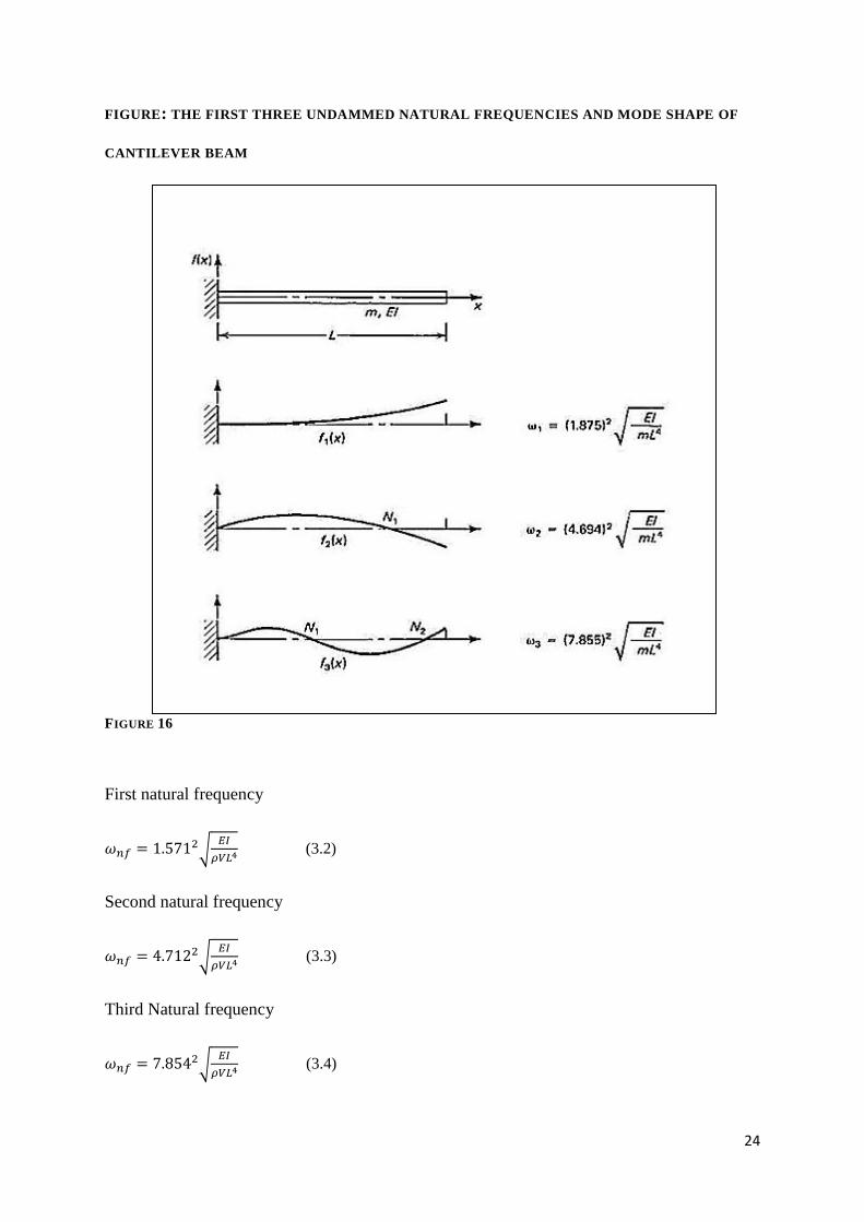
FIGURE: THE FIRST THREE UNDAMMED NATURAL FREQUENCIES AND MODE SHAPE OF
CANTILEVER BEAM
FIGURE 16
First natural frequency
√
(3.2)
Second natural frequency
√
(3.3)
Third Natural frequency
√
(3.4)

25
Where m=
The natural frequency is related with circular natural frequency as
(3.5)
Length of arm; L=0.16m;
√
Where: h= 0.006m; b= 0.03m; L=0.16m; E=2.5GPa; = 1188kg/m3
Area = 0.03*0.006 = 1.8*10-4
m2
Volume = 0.03*0.006*0.16=2.88*10-5
m3
I = (0.03(0.006)3)/12 = 5.4*10
-10 m
4
1st natural frequency mode 1;
√
√(1.35/2.69 * 10-4)
2nd
natural frequency mode 2;
√
√(1.35/2.69 * 10-4)
3rd natural frequency mode 3;

26
√
√(1.35/2.69 * 10-4)

27
4.1.5.3: Finite element analysis (FEA)
First, a stable RCAV platform is necessary to achieve efficiency and reliability in operation.
Before we analyze the structural behaviour, the structural components may vibrate due to
mechanical and aerodynamic effects, this is mainly due to rotating rotors mounted on the tip
of the quadrotor arms, and these rotors create a periodic excitation which causes vibration. To
conduct fast and reliable structure analysis, finite element analysis (FEA) via Solidworks was
used in the present work. Discredited into finite number of elements, the stresses and
displacements of parts and assemblies can be calculated. On the other hand, frequency
response analysis was used to determine the displacement response of the model when
external steady state oscillatory excitation (simulating rotor rotation) is applied. Below is a
sample of stress analysis done on the arm of the quadrotor the full report of the analysis is
attached in the appendix.
Von Mises’ stress
The von Mises stress is used to predict yielding of materials under any loading condition
from results of simple uniaxial tensile tests. The von Mises stress satisfies the property that
two stress states with equal distortion energy have equal von Mises stress. This is
accomplished by calculating the von Mises stress and comparing it to the material's yield
stress, which constitutes the von Mises Yield Criterion.
In this case, a material is said to start yielding when its von Mises stress reaches a critical
value known as the yield strength, .
Mathematical Formulation of Von Mises’ Stress
Mathematically the von Mises yield criterion is expressed as:
Where is the yield stress of the material in pure shear. As shown later in this article, at the
onset of yielding, the magnitude of the shear yield stress in pure shear is √3 times lower than
the tensile yield stress in the case of simple tension. Thus, we have:
Where is the yield strength of the material. If we set the von Mises stress equal to the
yield strength and combine the above equations, the von Mises yield criterion can be
expressed as:

28
√
or
Calculating acrylic Von Mises stress;
=
√
FIGURE 17

29
FIGURE 18

30
4.2: FRAME PRODUCTION AND QUADCOPTER ASSEMBLY
4.2.1: Component parts of a Quadrotor.
TABLE 2
Qty Parts /material Description
1 Frame (acrylic) 10 pieces (4 arms, landing gear of 6mm thickness and upper and
lower surface part 3mm thickness)
2 Nuts and Bolts 16 bolts of 3mm diameter, 16 bolts and nuts of 5mm diameter
3 Motors Aeolus series 2208-920Kv weighing 49.5g
4 Propellers 10×4.5
5 Battery 5500MAH 4S LiPo 81.2Wh
6 Radio transmitter Turnigy 9X 8 Channel
7 Radio receiver Turnigy RX
8 APM 2.6 controller Arducopter Pilot Mega controller
4.2.2: Cutting out the Frame
After designing the frame using Solidworks software converted the designs to CorelDraw
software since it is compatible with laser cutter. We used the laser cutter available in
FABLAB to cut our design on acrylic sheet. The upper and lower surface was cut on 3mm
thickness acrylic and the four arms were cut on 6 mm thickness acrylic.
FIGURE 19

31
4.2.3: Assembling Frame
After cutting the design on the acrylic sheet we had six different pieces. We used steel bolts
and nuts (3mm diameter and 50mm long bolts) to hold the pieces tight together.
4.2.4: Fixing motors.
We used screws to fix the four brushless motors, each on the frame’s arms. A piece of rubber
was placed in between the motor and the acrylic surface so as to damp vibrations from the
motors while in motion.
4.2.5: Assembling electronics
We placed the battery on the top surface of one centreplate, with the power distribution board
on the other side of this surface. The flight controller was placed on the middle surface with
its arrow facing front. The radio receiver and voltage regulator were placed on each side of
the controller. ESC’s were fixed on the top surface too, with the cables running to the middle
plate containing the controller.
The following is a table showing how the receiver was connected to the flight controller;
TABLE IV RECEIVER CHANNEL TO FLIGHT CONTROLLER CONNECTION
Receiver Channel Flight Controller
Aileron --- Aileron
Elevator --- Elevator
Throttle --- Throttle
Rudder --- Rudder
AUX1 --- AUX
AUX2 AUX
POWER POWER

32
4.2.6: Testing the Flight Control Board
The flight controller was connected to a laptop by USB cable and software called APM
(ArduPilot Mega) planner was downloaded from the internet. It was simple to set up and
install. This software is also easy to use and when we opened it, we went to the initial setup
page and followed the step by step instructions it gave us. After firmware was uploaded into
the flight controller, we began calibration of the accelerometer which involved placing the
controller on level surface and normal to the surface. After this was done, we setup the radio
by first binding the transmitter to its receiver, then pressing and toggling the transmitter
controls and switches. As the switches changed, the software on the laptop also responded
accordingly, and when the calibration was complete, we then calibrated the ESC’s.
4.2.7: Calibration of Electronic Speed Controllers
First, we turned on the transmitter with throttle at maximum. Then, the battery was connected
to the machine, with red and blue blinking signals on the flight controller. The battery was
disconnected and reconnected and a number of beeps from the motors indicated that the
motors were in calibration mode. They beeped again to indicate maximum throttle, and thus
the throttle was moved to minimum position with the motors beeping in response. With this,
calibration was complete and a slight increase in throttle was accompanied by rotary motion
of the motors. With that done, calibration is over and the battery is disconnected.
Note that this calibration is done without propellers on, as they will cause movement of the
machine.
4.2.8: Arming the motors
For us to fly, we have to activate the motors first, which is known as arming. Similarly, when
switching off the machine, you disarm it first. To arm, you hold the throttle at minimum and
rudder right for five seconds when the copter is on. Initially, a blinking red light on the APM
indicates that it has not yet been armed. When it is armed, the blinking red becomes constant
and is now ready to fly.
When done with flying, the hold roll left for five seconds; and the controller will disarm. This
is indicated by the constant, steady red light on the controller starting to blink.

33
4.3: MODEL PERFORMANCE CHARACTERISTICS After assembly of the various parts, we took our model to the field to perform various tests
and to even try fly it for the very first time. The tests were mostly successful and it took off
from the ground. We however realised the model was dragging to one side. Since all software
and hardware tests were a success, the reason for this dragging could be nothing else but
weight, an uneven distribution of it. We decided to change the position of the battery from the
top surface to the bottom surface .This made the model more stable by lowering its centre of
gravity .This also evened out the weight of the model.

34
4.4 COMPUTER SIMULATION
STRESS ANALYSIS OF THE FRAME
Model Reference Properties
Name: Acrylic (Medium-high impact)
Model type: Linear Elastic Isotropic Default failure criterion: Max von Mises Stress
Yield strength: 4.5e+007 N/m^2 Tensile strength: 7.3e+007 N/m^2 Elastic modulus: 3e+009 N/m^2
Poisson's ratio: 0.35 Mass density: 1200 kg/m^3
Shear modulus: 8.9e+008 N/m^2 Thermal expansion
coefficient: 5.2e-005 /Kelvin

35
Mesh type Solid Mesh
Mesher Used: Curvature based mesh
Jacobian points 4 Points
Maximum element size 0.74136 cm
Minimum element size 0.037068 cm
Mesh Quality High
Total Nodes 100096
Total Elements 57560
Maximum Aspect Ratio 8.4286
% of elements with Aspect Ratio < 3 97.9
% of elements with Aspect Ratio > 10 0
% of distorted elements(Jacobian) 0
Time to complete mesh(hh;mm;ss): 00:00:26
Computer name: ADMIN-HP71
Resultant Forces
Reaction Forces

36
Selection set Units Sum X Sum Y Sum Z Resultant
Entire Model N 8.08388e-007 -31.3863 -1.0632e-005 31.3863
Reaction Moments
Selection set Units Sum X Sum Y Sum Z Resultant
Entire Model N.m 0 0 0 0
Study Results
Name Type Min Max
Stress1 VON: von Mises Stress 9.02747e-005 N/m^2 Node: 82239
2.2652e+006 N/m^2 Node: 78374
assembly final-Static 1-Stress-Stress1
Name Type Min Max
Displacement1 URES: Resultant Displacement 0 mm Node: 21
1.1211 mm Node: 61479

37
assembly final-Static 1-Displacement-Displacement1
Name Type Min Max
Strain1 ESTRN: Equivalent Strain 3.02184e-014 Element: 49126
0.000512471 Element: 42683
assembly final-Static 1-Strain-Strain1

38
STRESS ANALYSIS OF THE ARM REPORT
Model name: final2
Current Configuration: Default Solid Bodies
Document Name and Reference
Treated As
Volumetric Properties
Document Path/Date Modified
Boss-Extrude1
Solid Body
Mass:0.0325762 kg
Volume:2.71469e-005 m^3
Density:1200 kg/m^3
Weight:0.319247 N
C:\Users\Public\Documents\solidworks project\final2.SLDPRT Mar 21 13:47:15 2016

39
Model Reference Properties
Name: Acrylic (Medium-high impact)
Model type: Linear Elastic Isotropic Default failure criterion: Max von Mises Stress
Yield strength: 4.5e+007 N/m^2 Tensile strength: 7.3e+007 N/m^2 Elastic modulus: 3e+009 N/m^2
Poisson's ratio: 0.35 Mass density: 1200 kg/m^3
Shear modulus: 8.9e+008 N/m^2 Thermal expansion
coefficient: 5.2e-005 /Kelvin
Mesh Information Mesh Information - Details
Total Nodes 13256
Total Elements 7682
Maximum Aspect Ratio 4.3662
% of elements with Aspect Ratio < 3 99.5
% of elements with Aspect Ratio > 10 0
Mesh type
Solid Mesh
Mesher Used: Standard mesh
Automatic Transition: Off
Include Mesh Auto Loops: Off
Jacobian points 4 Points

40
Element Size 0.300648 cm
Tolerance 0.0150324 cm
Mesh Quality High
Resultant Forces
Reaction Forces
Selection set Units Sum X Sum Y Sum Z Resultant
Entire Model N 0.00518751 -9.80852 0.0019567 9.80853
Reaction Moments
Selection set Units Sum X Sum Y Sum Z Resultant
Entire Model N.m 0 0 0 0
Study Results
Name Type Min Max
Stress1 VON: von Mises Stress 1066.29 N/m^2 Node: 12680
7.6927e+006 N/m^2 Node: 47
final2-Static 1-Stress-Stress1
Name Type Min Max
Displacement1 URES: Resultant Displacement 0 mm Node: 137
3.19853 mm Node: 85

41
final2-Static 1-Displacement-Displacement1
Name Type Min Max
Strain1 ESTRN: Equivalent Strain 3.34694e-007 Element: 3134
0.00146319 Element: 2736
final2-Static 1-Strain-Strain1
Name Type
Displacement1{1} Deformed Shape

42
STRESS ANALYSIS OF THE STAND REPORT
Model name: final3
Current Configuration: Default
Solid Bodies Document Name and
Reference Treated As Volumetric Properties
Document Path/Date Modified
Boss-Extrude1
Solid Body
Mass:0.0251306 kg Volume:2.09422e-005 m^3
Density:1200 kg/m^3 Weight:0.24628 N
C:\Users\Public\Documents\solidworks
project\final3.SLDPRT Mar 21 13:47:07 2016
final2-Static 1-Displacement-Displacement1{1}

43
Material Properties
Model Reference Properties Components
Name: Acrylic (Medium-high impact)
Model type: Linear Elastic Isotropic Default failure criterion: Max von Mises Stress
Yield strength: 4.5e+007 N/m^2 Tensile strength: 7.3e+007 N/m^2 Elastic modulus: 3e+009 N/m^2
Poisson's ratio: 0.35 Mass density: 1200 kg/m^3
Shear modulus: 8.9e+008 N/m^2 Thermal expansion
coefficient: 5.2e-005 /Kelvin
SolidBody 1(Boss-Extrude1)(final3)
Curve Data:N/A
Components X Y Z Resultant
Reaction force(N) -0.00159386 0.00122606 31.3923 31.3923
Reaction Moment(N.m) 0 0 0 0
Mesh Information
Mesh type Solid Mesh
Mesher Used: Standard mesh
Jacobian points 4 Points
Element Size 0.275738 cm
Tolerance 0.0137869 cm
Mesh Quality High
Total Nodes 13476
Total Elements 8148
Maximum Aspect Ratio 4.5912
% of elements with Aspect Ratio < 3 99.9
% of elements with Aspect Ratio > 10 0
% of distorted elements(Jacobian) 0
Time to complete mesh(hh;mm;ss): 00:00:03
Computer name: ADMIN-HP71

44
Study Results
Name Type Min Max
Stress1 VON: von Mises Stress 0.00731602 N/m^2 Node: 5776
734641 N/m^2 Node: 12846
final3-Static 1-Stress-Stress1
Name Type Min Max

45
Displacement1 URES: Resultant Displacement 0 mm Node: 85
0.103582 mm Node: 566
final3-Static 1-Displacement-Displacement1
Name Type Min Max
Strain1 ESTRN: Equivalent Strain 1.52228e-006 Element: 1735
0.000207872 Element: 3097
final3-Static 1-Strain-Strain1

46
CHAPTER FIVE
CONCLUSION AND RECOMMENDATIONS
5.1: Discussion
The remote controlled Aerial Vehicle was designed using Solidworks and fabricated on
acrylic sheet using laser cutter machine. The analysis of the forces acting on the frame was
done using Solidworks software.
The prototype was developed using the frame that was fabricated in the lab. All the
electronics which include; motors, batteries, receiver, transmitter, Electrical Sensor Controls,
and multi rotor control board were locally sourced.
Finally the design of the Remote Controlled Aerial vehicle was simulated using Solidworks
to be able to pre-test the quadrotor on real flight.
5.2: Conclusion A remotely controlled aerial vehicle was designed and constructed. It was tested and
performance characteristics determined. Lift was achieved during tests. A computer
simulation of its performance in actual use was developed and attached to the report
5.3: Recommendations Further research should be carried out on the vibrations and damping mechanisms of the
quadcopter. During design of the frame, all electronic parts must be considered so as to easily
secure the parts into place. Geographic Positioning Systems to ensure full autonomy. The
simulation and modelling performed in this study will serve as the foundation for control
system design and localization system refinement in order to automate the navigation and
flight of the quadrotor. Additional design iterations of both software and hardware will allow
for improved position estimation reliability and accuracy which will, in turn, enable the
development of a robust quadrotor controller.

47
5.4: References APC Advanced precision composites propeller dataset. [Online]. Available:
Bouabdallah, S., Noth, A., Siegwart, R.,PID vs LQ Control Techniques Applied to an Indoor
Micro Quadrotor: Autonomous Systems Laboratory. Date Accessed: December 3, 2008
Bramwell‟s Helicopter Dynamics, Second Edition. Done, George. David Balmford. Library
of Flight Series. © 2001
D. Griffiths and J. Leishman, “A study of dual-rotor interference and ground effect using a
free-vortex wake model,” in Proc. of the 58th
Annual Forum of the American Helicopter
Society, (Montréal, Canada), 2002.
H. Huang, G. M. Hoffmann, S. L. Waslander, and C. J. Tomlin, “Aerodynamics and control
of autonomous quadrotor helicopters in aggressive maneuvering,” IEEE International
Conference on Robotics and Automation, pp. 3277–3282, May 2009.
H. R. Hossain and Dr. N. Kroughlicof, “Propeller dynamometer for small unmanned aerial
vehicle,” Memorial University of Newfoundland, St. John’s, NL, Canada.
http://www.apcprop.com/v/downloads/PERFILES_WEB/datalist.asp
J. B Brandt and M. S. Selig. Propeller performance data at low Reynolds numbers. Technical
report, University of Illinois, 2011.
K. Kotwani, S. K. Sane, H. Arya, K. Sudhakar, “Experimental Characterization of propulsion
system for mini aerial vehicle,” 31st National Conference on FMFP, December 16-18, 2004,
Jadavpur University, Kolkata.
K. M. Asson and P. F. Dunn, “Compact dynamometer system that can accurately determine
propeller performance,” Journal of Aircraft, vol.29, pp. 8-9, January-February 1992.
O. Gur and A. Rosen, “Optimizing electric propulsion systems for unmanned aerial vehicles,”
in journal of Aircraft Vol. 46, No. 4,Technion – Israel Institute of Technology, Haifa 32000,
Israel, July-August 2009.
Olson, E. (2010). LCM: Lightweight Communications and Marshalling. IEEE/RSJ
International Conference on Intelligent Robots and Systems (IROS).
P.J. Bristeau, P. Martin, E. Salaün, N. Petit, “The role of propeller aerodynamics in the model
of a quadrotor UAV,” Proceedings of the European Control Conference 2009, Budapest,
Hungary, August 2009.
Propeller database. [Online] Available:
http://aerospace.illinois.edu/mselig/props/propDB.html
S. Bouabdallah, A. Noth, and R. Siegwart, “PID vs LQ control techniques applied to an
indoor micro quadrotor,” IEEE/RSJ International Conference on Intelligent Robots and

48
Systems, vol. 3, pp. 2451–2456, 2004.
Sobers, D. Michael, Jr., Girish Chowdhary, and Eric N. Johnson. "Indoor Navigation for
Unmanned Aerial Vehicles." Proc. of AIAA Guidance, Navigation, and Control Conference,
Chicago, IL. Reston, VA: American Institute of Aeronautics and Astronautics, 2009. 1-29.
Ardupilot.com/downloads/?did=2.
dev.ardupilot.com/wiki/supported-autopilot-controller-boards/
en.m.wikipedia.org/wiki/History_of_unmanned_aerial_vehicles
www.airspacemag.com/photos/a-brief-history-of-unmanned-aircraft-17407243
en.m.wikipedia.org/wiki/Breguet-Richie_Gyroplane
quadcopterarena.com/the-history-of-drones-and-quadcopters/
oddcopter.com/2012/02/06/choosing-quadcopter-motors-and-props/
blog.oscarliang.net/how-to-choose-motor-and-propeller-for-quadcopter/

49
APPENDIX
APM PLANNER INTERFACE