COLLABORATIVE PARAMETRIC BIM - …papers.cumincad.org/data/works/att/ascaad2010_127.content.pdf ·...
8
COLLABORATIVE PARAMETRIC BIM HANS HUBERS Delft University of Technology, the Netherlands [email protected] Abstract. Digital architectural design actually is dominated by Building Information Modeling (BIM) and parametric methods, which are not always compatible with IFC, the ISO standard for BIM. A possible way out of this paradox could be that a multidisciplinary team from the start designs a full parametric conceptual IFC-based BIM database located on a server with discipline specific software in a combination of co-location and video-conferencing, using scripts that only create objects if they are not already in the database and otherwise only adapt their properties. 1. Introduction The main research question is: “What is a good method for collaborative architectural design”. We define that as multidisciplinary simultaneous design from the very start of a project. It is also called co-design or concurrent engineering. Sub-questions are: “Should we develop specific software”, “Should we use parametric software”, “Should we use standards like IFC”. The methods used to answer these questions are: literature study, development of prototype software, testing with case studies. Building Information Modeling, the process of making a Building Information Model, asks for collaborative design (Eastman et al., 2008; Hardin, 2009). The pressure to use IFC based BIM is growing. IFC is an ISO standard. A good introduction to IFC-based BIM is to be found in Khemlani (2004). Autodesk adopted it a.o. in Autodesk Revit. Other major CAD developers in the AEC industry support it too. The Dutch part of the buildingSMART association, which develops IFC, states in her newsletter that the directions of Governmental Services of U.S., Denmark, Finland, Norway and the Netherlands signed an agreement for adopting IFC based BIM for all major government projects (BS, 2010). Numerous magazines
Transcript of COLLABORATIVE PARAMETRIC BIM - …papers.cumincad.org/data/works/att/ascaad2010_127.content.pdf ·...

COLLABORATIVE PARAMETRIC BIM
HANS HUBERS Delft University of Technology, the Netherlands
Abstract. Digital architectural design actually is dominated by Building Information Modeling (BIM) and parametric methods, which are not always compatible with IFC, the ISO standard for BIM. A possible way out of this paradox could be that a multidisciplinary team from the start designs a full parametric conceptual IFC-based BIM database located on a server with discipline specific software in a combination of co-location and video-conferencing, using scripts that only create objects if they are not already in the database and otherwise only adapt their properties.
1. Introduction
The main research question is: “What is a good method for collaborative architectural design”. We define that as multidisciplinary simultaneous design from the very start of a project. It is also called co-design or concurrent engineering. Sub-questions are: “Should we develop specific software”, “Should we use parametric software”, “Should we use standards like IFC”. The methods used to answer these questions are: literature study, development of prototype software, testing with case studies.
Building Information Modeling, the process of making a Building Information Model, asks for collaborative design (Eastman et al., 2008; Hardin, 2009). The pressure to use IFC based BIM is growing. IFC is an ISO standard. A good introduction to IFC-based BIM is to be found in Khemlani (2004). Autodesk adopted it a.o. in Autodesk Revit. Other major CAD developers in the AEC industry support it too. The Dutch part of the buildingSMART association, which develops IFC, states in her newsletter that the directions of Governmental Services of U.S., Denmark, Finland, Norway and the Netherlands signed an agreement for adopting IFC based BIM for all major government projects (BS, 2010). Numerous magazines

128 HANS HUBERS
and conferences are focusing on this subject. There are many websites and internet groups about BIM.
The benefits of BIM are clash detection, quantity takeoff and estimating, construction analysis and planning, integration with cost and schedule control and other management functions, offsite fabrication, verification, guidance and tracking of construction activities, and automated code checking (Eastman et al., 2008). We could add the simulation of the building use to this. VR systems like CAVEs and Head Mounted Displays are used for that. We developed a lab called protoSPACE which uses these techniques (Hubers, 2009).
Besides benefits of BIM there are also drawbacks. Eastman et al. mention that “A mechanism does not yet exist for rewarding designers that provide rich information models (Eastman et al., 2008).” A survey of 1266 AIA member architectural offices in 2007 showed that 74% use 3D CAD, but mainly for visualization purposes (Gonchar, 2007).
The question remains how a multidisciplinary design team can apply Integrated Design & Delivery Solutions (CIB, 2009). Through trial and error with multidisciplinary teams in our lab protoSPACE, using discipline specific software applications we are developing and testing different methods.
Figure 1 Design process (Lawson, 2006)
2. Collaborative architectural design
Before we can develop collaborative architectural design methods and tools we first have to analyze the design process. An extensive study of the work of Foqué, Shön, Akin, de Jong and van der Voort, Moughtin et al., Stellingwerff and Hamel, to name but a few exponents, leads to the conclusion that the two most relevant processes in collaborative

COLLABORATIVE PARAMETRIC BIM 129
architectural design are the iterative development and evaluation of alternatives in accordance with criteria (Hubers, 2008). This is confirmed by the standard work of Lawson (2006), provided that we see creation as the combination of analysis and synthesis (Figure 1). The analysis of the design process led to a collaborative design method (Figure 2) and an application prototype known as COLAB (Figure 3) that was tested by a team consisting of an architect, a structural advisor, an installation advisor and a cost advisor. The test case was the Rotterdam Central Railway Station design. The method consisted of importing the brief with its m2 and m3, functions and constraints into a 3D model of the environment. The Virtools application prototype converted this information into a row of half transparent colored volumes with function names above them (which, if desired, can be hidden). Different local tools support the distribution of these Functional Volumes over the site. They can be visualized as blocks or as spheres. This work is done individually by every team member, thus resulting in a diversity of versions of the layout in a central database.
Figure 2 COLAB IDEF-0 Process diagram
The work cannot be executed simultaneously in multi-player mode because if one team member tries to make a tower out of the volumes while, for instance, another is creating a square they will never obtain a result. Messages indicate when team members have saved their work so that others can look through the versions and either comment or continue working on a particular version.
When there are enough versions, the team members discuss them by means of textual chat, which is stored in the database, and by providing a criteria overlay-matrix, which they supplement with the relevant criteria. They summarize this by enumerating the advantages and disadvantages of every version of the concept. The next rounds then follow, in which they try to integrate the advantages and eliminate the disadvantages. Finally the team members choose one version. This volumetric model can be used as a reference layer for the next phase: the actual design phase.

130 HANS HUBERS
Every team member then reveals which building elements are needed and what they look like. They do this from the point of view of their own discipline, so this can be a simultaneous process. The tool we developed for this particular purpose is a multi-player Virtools application that supports multicolored 3D curves. The structural advisor uses red lines for the supporting structures; the installation advisor uses blue lines for the conduits and other installation elements while the architect produces yellow lines to show his design intentions (Figure 3). They add arrows with comments (call-outs), while chatting and using the criteria-overlay matrix. The cost expert, who does not draw lines, interacts by making comments. The same method and different versions will ultimately lead to the final concept. The final result needs to be exported to the team members’ various software applications for further calculations and modeling.
Figure 3 The COLAB prototype
The main conclusions to be drawn from the COLAB project are these: • It appeared to be possible to develop a working software application
prototype in Virtools with which a multidisciplinary design team is able to cooperate in a virtual 3D environment in real-time via the Internet.
• Only the architect in the test team appeared to be able to develop a conceptual design with this prototype in the space of half a day.
• The test team advisors need to be trained in the developing and 3D modeling of conceptual building designs. Only then will they be able to effectively participate in collaborative architectural design based on this method and prototype.
COLLABORATIVE PARAMETRIC BIM 131
• The training of a design team is expensive. Remaining true to the principle of developing alternatives to choose
between, we now plan to continue our research by focusing on a method in which every team member uses the software most appropriate to his discipline. One of the main problems is how to exchange data between those applications. As mentioned above, IFC-based BIM is developed for that very purpose. Is it applicable though in this context?
3. IFC based BIM
IFC is developed by the buildingSMART International group which now consists of 14 regional world-wide alliances. The Benelux alliance, for instance, has 40 members including such professionals as: contractors, architects, engineers, research institutes, building companies and software vendors. IFC became a standard of the International Standard Organization and is now widely supported by more than 20 software vendors (IFC-wiki, 2010).
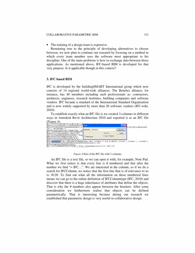
To establish exactly what an IFC file is we created 3 columns in different ways in Autodesk Revit Architecture 2010 and exported it as an IFC file (Figure 4).
Figure 4 Part of the IFC file with 3 columns
An IFC file is a text file, so we can open it with, for example, Note Pad. What we first notice is that every line is # numbered and that after the number we find “= IFC…”. We are interested in the column, so if we do a search for IFCColumn, we notice that the first line that is of relevance to us is: #120. To find out what all the information on these numbered lines means we can go to the online definition of IFCColumntype (IFC, 2010) and discover that there is a huge inheritance of attributes that define the objects. That is why the # numbers also appear between the brackets. After some consideration we furthermore realise that objects can be defined parametrically. That is interesting because during our research we established that parametric design is very useful in collaborative design.

132 HANS HUBERS
4. Parametric design
Parametric design software is CAD software in which objects and their attributes remain variable. Instead of deleting and redrawing the design or parts of the design, the user can just change the parameters and the design will adapt itself. This can be very efficient in collaborative design, where often changes in the design have to be modeled in order to be evaluated with the software of advisors.
There are several kinds of parametric design software (Hubers 2008). Within the context of this paper it is important to distinguish between object parametric, process parametric and full parametric CAD. Object parametric means that the object attributes are variable, e.g. the dimensions of a column. Process parametric means that algorithms generate a design or part of a design, e.g. a script that generates a skin surface, floors, vertical shaft, columns etc. (Figure 5). Full parametric includes both kinds of CAD.
Unfortunately IFC only supports object parametric CAD. This means that process and full parametric CAD would, in principle, be able to write IFC data, but reading IFC data is of no use. To explain this we first have to know how full parametric CAD works.
We tested several parametric CAD applications and used them in our research and education. We started with Bentley’s Generative Components and then went on to Digital Project from Gehry Technology. At the moment we are testing and working with a parametric design plug-in called Grasshopper for Rhino from McNeel and Autodesk’s Revit Architecture 2010. We used the parametric office design case study, which we had already developed in Digital Project (Hubers 2009).
What we are particularly interested in is the double curved façade with pipes that serve as columns and stability frames at the same time (Figure 5). The right window in this figure is Grasshopper. It is in fact a script created by a flow diagram of components. A slider represents the radius parameter of the façade surface. The surface is intersected by a series of horizontal planes. This in turn generates a series of circles that are then used to make the floors by means of extrusion. The central shaft is also generated by certain Grasshopper components and subtracted from the floors. Another slider defines how many points are needed on the circles to create the tubes and connection knots. A VB-script component takes care of connecting up the right points to define the pipes.
The development of a script like this would take some days and with all the connections required to engineering and cost estimation software it would probably take a number of weeks for a trained team to complete. But adapting the concept for specific situations and clients would take only some days. We should therefore consider continuing with full parametric software, even if there is no way to use IFC. Since IFC is object-based, there

COLLABORATIVE PARAMETRIC BIM 133
is no automatic way to derive from the list of objects how to adapt the script. However it would be wise to make an IFC file anyway, if only for future reference.
Figure 5 Parametric office design in Rhino/Grasshopper.
5. Conclusion
The conclusion of the research is that development of specific collaborative architectural design software is not a good approach. Design team members should use appropriate software to their disciplines.
It has been demonstrated that full parametric design has many advantages for collaborative design. There is an enormous potential for parametric design in the building industry (Lee et. al., 2006). Recently structural engineers started using parametric design software too (Breider and Coenders, 2009). And though we may wonder if architects are willing to work along with a structural engineer using their criteria instead of basing the concept on a desert flower like with the Burj Dubai, it is obvious that this parametric approach has many potentials. Any building professional can confirm that building components are much interrelated. A modification in the foundation has consequences through the whole building and even in the roof and vice versa. So what is more logical and natural than to use parametrical relations for that?
But also has been demonstrated that full parametric design is not compatible with IFC. It can produce IFC but there is no way (yet) that a parametric script can use the information it reads in such a file. Now the

134 HANS HUBERS
challenge is to find ways to make object parametric designs with affordable process parametric software like Rhino/Grasshopper. Maybe it is possible to develop a parametric script that only creates objects if they are not already in the model or in the IFC file it is reading. In that case it only checks if the attributes of those objects are conform the IFC file and alters them if needed. Further research in this domain is needed to solve this.
An interesting study could be to have a multidisciplinary team from the start design a full parametric conceptual IFC-based BIM located on a server with discipline specific software in a combination of co-location and video-conferencing.
References
BREIDER, J. AND COENDERS, J., 2009. StructuralComponents: parametric associative structural design tools for high-rise. In Innovations for Building and Construction, ed. E. Dado, R. Beheshti and K. Zreik, EuropIA, Paris.
BS 2010. Newsletter April 2009 nr1 available at http://bw-dssv07.bwk.tue.nl/-files/newsletters/nieuwsbrief-buildingsmart-22-04-2009.pdf accessed 3-1-2010.
CIB 2010. White Paper on IDDS Integrated Design & Delivery Solutions. Eds.: R. Owen. Available at: http://heyblom.websites.xs4all.nl/website/newsletter/0909/idds_pub.pdf. Accessed on 9-3-2010.
EASTMAN, C., TEICHHOLZ, P., SACKS, R. AND LISTON, K., 2008. BIM Handbook. Wiley, Hoboken, New Jersey, U.S.A.
GONCHAR, J., 2007. To architects, building information modeling is still primarily a vizualisation tool. In Architectural Record 07 27 2007. Also available at: http://archrecord.construction.com/features/digital/archives/0607dignews-2.asp
HARDIN, B., 2009. BIM and construction management. Sybex, Indianapolis, Indiana, U.S.A.
HUBERS, J.C., 2008. Collaborative architectural design in virtual reality. PhD diss. Faculty of Architecture of Delft University of Technology, The Netherlands. Also available at http://www.bk.tudelft.nl/users/Hubers/internet/DissertatieHansAURHORNAME(3).pdf.
HUBERS, J.C., 2009. Collaborative design in Protospace 3.0. In Changing roles; new roles,
new challenges, ed: H. Wamelink, M. Prins and R. Geraedts. TU Delft Faculty of Architecture Real Estate & Housing, Delft. Also available atwww.changingroles09.nl.
IFC 2010. http://www.iai-tech.org/ifc/IFC2x3/TC1/html/index.htm. Accessed 15-2-2010. IFC-wiki 2010. http://en.wikipedia.org/wiki/Industry_Foundation_Classes. Accessed on 9-
10-2010. KHEMLANI, L., 2004. The IFC Building Model: A Look Under the Hood. In AEC-bytes.
Available at http://www.aecbytes.com/feature/2004/IFCmodel.html. LAWSON, B.R., 2006. How designers think. Architectural Press/Elsevier, Oxford. LEE, G., SACKS, R. AND EASTMAN, C.M., 2006. Specifying parametric building object
behaviour (BOB) for a building information modeling system. In Automation in
Construction 15 (2006) 758-776.