Collaborative Construction - University of Torontotovi/papers/collaborativeConstruction... ·...
12
184 Collaborave Construcon 1 Human and robot collaborave building process. 2 Final assembled structure composed of over 200 unique modules. 3 Tensegrity Module. 4 Pin-hooking detail. Human and Robot Collaboraon Enabling the Fabricaon and Assembly of a Filament-Wound Structure ABSTRACT In this paper, we describe an interdisciplinary project and live-exhibit that invesgated whether untrained humans and robots could work together collaboravely towards the common goal of building a large-scale structure composed out of robocally fabricated modules using a filament winding process. We describe the fabricaon system and exhibion setup, including a custom end effector and tension control mechanism, as well as a collaborave fabricaon process in which instrucons delivered via wearable devices enable the trade-off of producon and assembly tasks between human and robot. We describe the necessary roboc developments that facilitated a live fabricaon process, including a generic robot inverse kinemac solver engine for non-spherical wrist robots, and wireless network communicaon connecng hardware and soſtware. In addion, we discuss computaonal strategies for the fiber syntax generaon and roboc moon planning which migated constraints such as reachability, axis limitaons, and collisions, and ensured predict- able and therefore safe moon in a live exhibion seng. We discuss the larger implicaons of this project as a case study for handling deviaons due to non-standardized materials or human error, as well as a means to reconsider the fundamental separaon of human and roboc tasks in a producon workflow. Most significantly, the project exemplifies a hybrid domain of human and robot collaboraon in which coordinaon and commu- nicaon between robots, people, and devices can enhance the integraon of roboc processes and computaonal control into the characterisc processes of construcon. Lauren Vasey, Long Nguyen ICD, University of Stugart Tovi Grossman Autodesk UI Research Heather Kerrick Autodesk Applied Research Danil Nagy The Living, Autodesk Research Evan Atherton, David Thomasson, Nick Cote Autodesk Applied Research 1 Tobias Schwinn ICD, University of Stugart David Benjamin The Living, Autodesk Research Maurice Con Autodesk Applied Research George Fitzmaurice Autodesk UI Research Achim Menges ICD, University of Stugart
Transcript of Collaborative Construction - University of Torontotovi/papers/collaborativeConstruction... ·...

184
Collaborative Construction
1 Human and robot collaborative building process.
2 Final assembled structure composed of over 200 unique modules.
3 Tensegrity Module.
4 Pin-hooking detail.
Human and Robot Collaboration Enabling the Fabrication and Assembly of a Filament-Wound Structure
ABSTRACTIn this paper, we describe an interdisciplinary project and live-exhibit that investigated whether untrained humans and robots could work together collaboratively towards the common goal of building a large-scale structure composed out of robotically fabricated modules using a filament winding process. We describe the fabrication system and exhibition setup, including a custom end effector and tension control mechanism, as well as a collaborative fabrication process in which instructions delivered via wearable devices enable the trade-off of production and assembly tasks between human and robot. We describe the necessary robotic developments that facilitated a live fabrication process, including a generic robot inverse kinematic solver engine for non-spherical wrist robots, and wireless network communication connecting hardware and software. In addition, we discuss computational strategies for the fiber syntax generation and robotic motion planning which mitigated constraints such as reachability, axis limitations, and collisions, and ensured predict-able and therefore safe motion in a live exhibition setting.
We discuss the larger implications of this project as a case study for handling deviations due to non-standardized materials or human error, as well as a means to reconsider the fundamental separation of human and robotic tasks in a production workflow. Most significantly, the project exemplifies a hybrid domain of human and robot collaboration in which coordination and commu-nication between robots, people, and devices can enhance the integration of robotic processes and computational control into the characteristic processes of construction.
Lauren Vasey, Long NguyenICD, University of Stuttgart
Tovi GrossmanAutodesk UI Research
Heather KerrickAutodesk Applied Research
Danil Nagy The Living, Autodesk Research
Evan Atherton, David Thomasson, Nick CoteAutodesk Applied Research
1
Tobias Schwinn ICD, University of Stuttgart
David BenjaminThe Living, Autodesk Research
Maurice ContiAutodesk Applied ResearchGeorge FitzmauriceAutodesk UI Research
Achim MengesICD, University of Stuttgart

185 GENERATIVE ROBOTICS
2
INTRODUCTION Though robotic fabrication has challenged standardized means of production for the architecture and manufacturing indus-tries, the specialized knowledge and skill set that robots require, and the organization and development of customizable robotic processes, are significant logistical challenges which increase costs, compartmentalize production and assembly tasks, and favor linear, file-to-factory production chains.
Though active research is being done to introduce robots and other fabrication equipment directly onto the construction site (Helm et al. 2012, 2014), the use of robotic fabrication in large-scale projects often necessitates a workflow in which components are processed offsite in a factory or lab by special-ists to be later transported, organized, and then assembled onsite by hand. This type of workflow provides little recourse if unexpected tolerances or deviations are encountered during the assembly and construction process.
Augmenting physical construction practices with digital mech-anisms and just-in-time production can offer several benefits to existing protocols. By involving humans directly within the robotic fabrication process, and providing them with instructions through wearable interfaces, the separation of tasks within the production pipeline can be specialized according to ability: a robot’s precision can be augmented by the fine motor control and cognitive ability of the human, and the monitoring of the process and feedback enabled through user interfaces allows the seamless trade-off of tasks between human and machine.
In this paper, we present a live exhibit and fabrication project that investigated whether humans and robots could work collaboratively and safely towards the common goal of fabri-cating and assembling a pre-designed large-scale structure. A prototypical robotic fabrication process was created that allowed the production of unique tensegrity modules which aggregated in a system. Tracking and monitoring of the current build status of the assembly enabled just-in-time instructions to be distrib-uted to the participants via a smartwatch interface. The ultimate application of such an investigation is to question whether global system monitoring instructions delivered through devices could enable the organization and coordination of workers, robotic processes, material, and components in a deployment scenario such as a construction site.
CONTEXTHuman and Robot CollaborationIn applications for the architecture, engineering, and construction (AEC) industries, the shift from robots engineered for task spec-ificity towards robots capable of generic tasks has enabled the
development of customizable fabrication processes and robotic control protocols (Menges and Schwinn 2012). The ability to further augment these robotic fabrication processes through connected devices and sensor feedback enables increased inte-gration and cross-linking between physical and digital domains (Menges 2015).
While robots in industry were originally purposed for the execu-tion of repetitive tasks, they are becoming increasingly involved in less structured and more complex tasks, including interacting directly with humans, an interdisciplinary field of research broadly considered human and robot interaction (HRI) (Goodrich and Schultz 2007). Production processes in the architecture and construction industries, which involve complex tasks in unstructured environments, are thus a highly relevant application scenario for the investigation of human and robot collaboration.
43

186
5
User Interfaces for FabricationWithin robotic fabrication research, user interfaces have enabled the possibility of connecting robotic actions directly with user input: Dörfler and Rust developed a set of tools and a flex-ible open interface to enable on-line control of a KUKA robot (Dörfler and Rust 2012). This investigation and others have primarily leveraged user interfaces as a medium by which the designer might influence the outcome of the process according to targeted feedback (Johns et al. 2014). In contrast, the inves-tigation provided here utilizes wearable interfaces as a means to communicate task instructions and protocols to an audience completely unfamiliar with the physical system and task. This investigation also builds upon investigations in industry. For example, sHop Architects utilized RFID tagging and a custom iOS application to organize fabricated building components for the Barclays center (Grogan 2014).
Filament Winding Coreless filament winding is a fabrication process whereby an industrial robot incrementally lays fibers on a minimal or tempo-rary formwork. This process is highly relevant as a customizable method which allows the formationof filament-based mate-rials, such as glass or carbon fiber. Coreless filament winding significantly differs from other fiber application processes in the aerospace and automotive industries, where a mold often serves as the basis on which fibers are applied. These alternate produc-tion methods are very limited, in that they can only be utilized to produce serially identical units. Robotic fabrication expands the limitations of these methods (Prado et al. 2014) and enables the
deposition of material precisely where it is needed, thus facili-tating the fabrication of highly differentiated structures.
FABRICATION SYSTEMTo investigate whether humans and robots could collaboratively fabricate and assemble a structure, a prototypical fabrication system utilizing a process of robotic filament winding was devel-oped based on the following criteria:
• Complexity of tasks: The fabrication system could not be overly simple, neither so difficult that someone unfamiliar with the task could complete it.
• Minimization of participation time: The total time required for a single participant in an exhibit was limited to 10 to 15 minutes.
• Utilization of machine vision: Adaptive regeneration of robotic control code would enable the use of non-standard materials and compensate for human error.
• Task allocation: A system in which the human user does the tasks that require fine motor control, and the robot those that require high precision, in which tradeoffs are facilitated through instructions delivered via wearable interfaces.
• User safety: Typical robotic safety procedures require that robotic control code is simulated before execution, or run in a safety mode at low speed. The exhibition format necessitated extra precautions to guarantee the reliability of the control code and safety of participants.
5 System monitoring, connected devices, custom tooling, robotic fabrication, and computational design enabled the development and realization of a human and robot collaborative building process.
Collaborative Construction Vasey, et al.
187 GENERATIVE ROBOTICS
Module DevelopmentA single tensegrity module was developed whereby three compression elements are held apart in a precise position during fabrication in order to align with each other in a global system. Bamboo was utilized for the compression members due to its energy efficiency and relative stiffness to weight, though it is non-standard material and thus ill-suited to traditional automa-tion techniques. A custom pin detail inserted into the end of the bamboo is utilized to catch and hold the string during winding.
Global DesignThe main driver of a global structure’s design was to describe a continuous doubly curved surface using modules of non-uniform shape composed of uniform length members. Assuming the modules are placed in the correct positions, the unique geom-etry of each module ensured that the structure would take the desired final form without any human oversight.
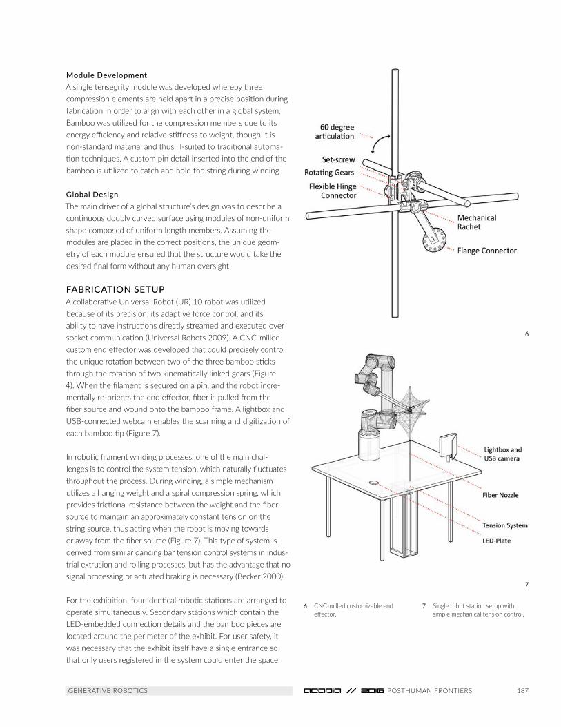
FABRICATION SETUP A collaborative Universal Robot (UR) 10 robot was utilized because of its precision, its adaptive force control, and its ability to have instructions directly streamed and executed over socket communication (Universal Robots 2009). A CNC-milled custom end effector was developed that could precisely control the unique rotation between two of the three bamboo sticks through the rotation of two kinematically linked gears (Figure 4). When the filament is secured on a pin, and the robot incre-mentally re-orients the end effector, fiber is pulled from the fiber source and wound onto the bamboo frame. A lightbox and USB-connected webcam enables the scanning and digitization of each bamboo tip (Figure 7).
In robotic filament winding processes, one of the main chal-lenges is to control the system tension, which naturally fluctuates throughout the process. During winding, a simple mechanism utilizes a hanging weight and a spiral compression spring, which provides frictional resistance between the weight and the fiber source to maintain an approximately constant tension on the string source, thus acting when the robot is moving towards or away from the fiber source (Figure 7). This type of system is derived from similar dancing bar tension control systems in indus-trial extrusion and rolling processes, but has the advantage that no signal processing or actuated braking is necessary (Becker 2000).
For the exhibition, four identical robotic stations are arranged to operate simultaneously. Secondary stations which contain the LED-embedded connection details and the bamboo pieces are located around the perimeter of the exhibit. For user safety, it was necessary that the exhibit itself have a single entrance so that only users registered in the system could enter the space.
6 CNC-milled customizable end effector.
7 Single robot station setup with simple mechanical tension control.
6
7

188
COLLABORATIVE FABRICATIONCollaborative Fabrication and Assembly ProcessUpon entrance to the exhibition, users would be outfitted with an Apple Watch, an Apple iPhone, and safety glasses. The user would then be guided by just-in-time instructions through the exhibition, beginning by obtaining materials. The custom iOS application and the specifics of the user interface are discussed in a separate paper, “Crowd-sourced Fabrication” (2016).
To fabricate a specific module at a robot station, the geometric properties of this unit are accessed from a database and then applied to an instantiation of the module in a CAD design envi-ronment. Correspondingly, the robot aligns itself perpendicularly to a reference surface for each bamboo part, so that the correct position and orientation is achieved, which allows the user to load the mechanical end effector by fastening and tightening a mechanical ratchet, a maneuver which utilizes the human’s dexterity and the robot’s precision. Confirmation that each part has been inserted correctly in the effector is confirmed from the
user’s watch before the robot proceeds. The robot then executes a custom scanning routine to re-digitize each tip correctly in space, re-generating the control code based on these deviations. Before uploading this code, the smartwatch interface prompts the user to confirm they are behind a safety line, and the winding routine executes at full speed.
During winding, a preliminary scaffolding layer is wound first to connect each end of bamboo to each of its neighbors without crossing or doubling the previously laid fibers. Final nebulous layers are wrapped, allowing the system to achieve an equi-librium condition, after which the tensegrity module can be removed from the effector by hand without significant deforma-tion. Instructions on the Apple Watch, and LED lights embedded within the connective modules between the parts themselves, then indicate to the user where to fasten the module on the existing structure by tightening two zip ties on the connection detail.
System CommunicationThe robotic winding process was embedded in global control framework, which coordinated active users, robotic stations, and the current build status. The “Foreman Engine,” the central brain in this framework, monitored and managed the overall progress of the construction and assembly, and systematically assigned the next part to the next available robot station (Lafreniere 2016).
The smartwatch devices worn by participants of the exhibit provided step-by-step instructions, and each user’s current
8 The Smartwatch delivered just-in-time instructions to participants.
9 The CNC-milled customizable end effector without a part loaded.
10 The effector could be fastened around an irregular piece of bamboo through the tightening of a ratchet.
8
109
Collaborative Construction Vasey, et al.

189 GENERATIVE ROBOTICS
status within the app was reported to the foreman engine. A series of iBeacons were additionally distributed throughout the exhibit to track the physical location of the workers, so that instructions could be presented automatically when a user arrived at a specific location (ibid.).
The robot server was configured as an in iteratively updating CAD environment on an individual PC (Figures 11 and 12). An update to a file structure on the control PC of each robot station communicated to the design environment to update the data structure of the current part, thereby triggering an update to the control code. Additional changes signified what control code to be immediately uploaded to the robot: either loadStick (A, B, C), scanParts(), or executeWinding().
Machine VisionThere were two main sources for error within this workflow: one being the deviations from an inherently variable material, and the other being the inherent source of error which arises when
humans make mistakes or cannot be precise. For example, by not tightening the ratchet of the end effector holding the part in its entirety, the pieces of bamboo could rotate slightly due to the high applied torque.
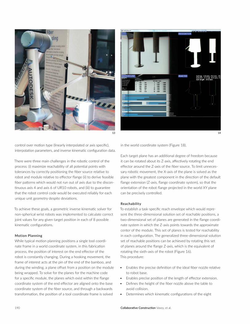
To mitigate these sources of error, a scanning process was imple-mented to individually measure each bamboo tip, recalculate the position of the tip relative to the robot flange, update the object-oriented structure of the module in the design environ-ment, and regenerate all of the robotic control code. A simple image analysis was utilized: for each of the 6 points of interest, the robot moves to a position in alignment with a plane in space. Based on simple image processing of two images, one taken through reflection, and the known mathematical location of the robotic position in space, the measured deviations of this pin are directly applied as a transformation of the pin in its local coordi-nate system (Figure 13).
Robotic Motion Planning for Filament WindingIn order to develop consistent and predictable robotic motion, it was necessary to develop algorithms that produce robotic winding patterns, methods that simulate these robotic paths, and methods that converted these paths into unambiguous robotic control code. Though software for the development and output of robotic control code exists by third party developers (Braumann and Brell-Cokcan 2014; Schwartz 2012; Elashry 2014), the kinematic complexity of the maneuvers necessary in a winding process, and the rather restrictive nature of the axis limits of Universal Robots, necessitated a stand-alone library for a comput-er-aided design environment (CAD) that would allow definitive
11
11 Detail of the robot server on a control PC.
12 The full inter-process system communication.
12
190
control over motion type (linearly interpolated or axis specific), interpolation parameters, and inverse kinematic configuration data.
There were three main challenges in the robotic control of the process: (i) maximize reachability of all potential points with tolerances by correctly positioning the fiber source relative to robot and module relative to effector flange (ii) to derive feasible fiber patterns which would not run out of axis due to the discon-tinuous axis 4 and axis 6 of UR10 robots, and (iii) to guarantee that the robot control code would be executed reliably for each unique unit geometry despite deviations.
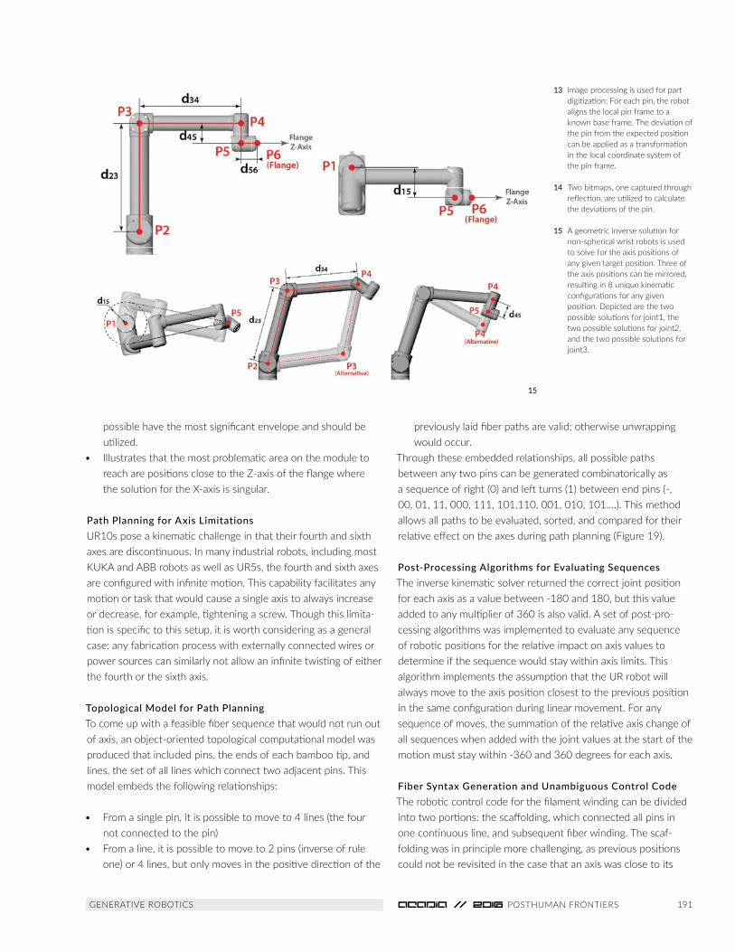
To achieve these goals, a geometric inverse kinematic solver for non-spherical wrist robots was implemented to calculate correct joint values for any given target position in each of 8 possible kinematic configurations.
Motion Planning While typical motion planning positions a single tool coordi-nate frame in a world coordinate system, in this fabrication process, the position of interest on the end effector of the robot is constantly changing. During a hooking movement, the frame of interest acts at the pin of the end of the bamboo, and during the winding, a plane offset from a position on the module being wrapped. To solve for the planes for the machine code for a specific module, the planes which exist within the flange coordinate system of the end effector are aligned onto the base coordinate system of the fiber source, and through a backwards transformation, the position of a tool coordinate frame is solved
in the world coordinate system (Figure 18).
Each target plane has an additional degree of freedom because it can be rotated about its Z-axis, affectively rotating the end effector around the Z-axis of the fiber source. To limit unneces-sary robotic movement, the X-axis of the plane is solved as the plane with the greatest component in the direction of the default flange extension (Z-axis, flange coordinate system), so that the orientation of the robot flange projected in the world XY plane can be precisely controlled.
ReachabilityTo establish a task-specific reach envelope which would repre-sent the three-dimensional solution set of reachable positions, a two-dimensional set of planes are generated in the flange coordi-nate system in which the Z-axis points towards the approximate center of the module. This set of planes is tested for reachability in each configuration. The generalized three-dimensional solution set of reachable positions can be achieved by rotating this set of planes around the flange Z-axis, which is the equivalent of rotating the sixth-axis of the robot (Figure 16). This procedure:
• Enables the precise definition of the ideal fiber nozzle relative to robot base.
• Enables precise position of the length of effector extension.• Defines the height of the fiber nozzle above the table to
avoid collision.• Determines which kinematic configurations of the eight
13 14
Collaborative Construction Vasey, et al.
191 GENERATIVE ROBOTICS
possible have the most significant envelope and should be utilized.
• Illustrates that the most problematic area on the module to reach are positions close to the Z-axis of the flange where the solution for the X-axis is singular.
Path Planning for Axis LimitationsUR10s pose a kinematic challenge in that their fourth and sixth axes are discontinuous. In many industrial robots, including most KUKA and ABB robots as well as UR5s, the fourth and sixth axes are configured with infinite motion. This capability facilitates any motion or task that would cause a single axis to always increase or decrease, for example, tightening a screw. Though this limita-tion is specific to this setup, it is worth considering as a general case: any fabrication process with externally connected wires or power sources can similarly not allow an infinite twisting of either the fourth or the sixth axis.
Topological Model for Path PlanningTo come up with a feasible fiber sequence that would not run out of axis, an object-oriented topological computational model was produced that included pins, the ends of each bamboo tip, and lines, the set of all lines which connect two adjacent pins. This model embeds the following relationships:
• From a single pin, it is possible to move to 4 lines (the four not connected to the pin)
• From a line, it is possible to move to 2 pins (inverse of rule one) or 4 lines, but only moves in the positive direction of the
previously laid fiber paths are valid; otherwise unwrapping would occur.
Through these embedded relationships, all possible paths between any two pins can be generated combinatorically as a sequence of right (0) and left turns (1) between end pins (-, 00, 01, 11, 000, 111, 101,110, 001, 010, 101….). This method allows all paths to be evaluated, sorted, and compared for their relative effect on the axes during path planning (Figure 19).
Post-Processing Algorithms for Evaluating SequencesThe inverse kinematic solver returned the correct joint position for each axis as a value between -180 and 180, but this value added to any multiplier of 360 is also valid. A set of post-pro-cessing algorithms was implemented to evaluate any sequence of robotic positions for the relative impact on axis values to determine if the sequence would stay within axis limits. This algorithm implements the assumption that the UR robot will always move to the axis position closest to the previous position in the same configuration during linear movement. For any sequence of moves, the summation of the relative axis change of all sequences when added with the joint values at the start of the motion must stay within -360 and 360 degrees for each axis.
Fiber Syntax Generation and Unambiguous Control CodeThe robotic control code for the filament winding can be divided into two portions: the scaffolding, which connected all pins in one continuous line, and subsequent fiber winding. The scaf-folding was in principle more challenging, as previous positions could not be revisited in the case that an axis was close to its
13 Image processing is used for part digitization; For each pin, the robot aligns the local pin frame to a known base frame. The deviation of the pin from the expected position can be applied as a transformation in the local coordinate system of the pin frame.
14 Two bitmaps, one captured through reflection, are utilized to calculate the deviations of the pin.
15 A geometric inverse solution for non-spherical wrist robots is used to solve for the axis positions of any given target position. Three of the axis positions can be mirrored, resulting in 8 unique kinematic configurations for any given position. Depicted are the two possible solutions for joint1, the two possible solutions for joint2, and the two possible solutions for joint3.
15

192
16
designers to ensure quality control, this project demonstrated that untrained workers—unfamiliar with both the necessary tasks required of them and the physical system itself—could success-fully collaborate with robots to build a large structure when provided with just-in-time instructions delivered through a wear-able device. Over 200 visitors came to the site to help build the 12 foot pavilion composed out of 224 unique tensegrity modules. The final structure was on display as a live collaborative building process and exhibit for over three days.
Despite the project’s successes, several aspects could have been improved. When an unanticipated error occurred, for example, the tension was too high for the safety settings of the UR robot, it triggered an error, and the entire part had to be discarded. Thus, one next step to improve the process would be to identify common errors, to determine how they are easily detected from sensor feedback or input from the user interface, and to tailor the information sent to the user based on this analysis.
One of the most significant limitations of the project was the use of a robot that had limited axis ranges. To enhance the interactivity of the process, and to make use of the robot’s inherent ability to achieve customizability, the design of the fiber layout could have become interactive or differentiated, in which case performance criteria, fabrication constraints, and user choice could have been integrated into a computational design tool and interface.
Scanning and digitizing the parts successfully enabled the utilization of non-standard materials. However, one missed opportunity was to store the deviations of the as-built geometry, and regenerate subsequent control code, allowing tolerances to be compensated for computationally as the construction and assembly process progressed (Vasey, Maxwell, and Pigram 2014).
DISCUSSIONAs a demonstrator, the project illustrates that interconnected devices, sensor feedback, and responses enabled through user interfaces enable new possibilities for reconsidering protocols for humans and robots to work together, particularly as applied in construction or fabrication processes which involve the coordina-tion and organization of many parts, processes, and people. More significantly, the project demonstrates the new possibility of a hybrid domain of robot and human collaboration in construction, in which coordination and communication between hardware and software facilitates new possibilities. These possibilities, including just-in-time production, tolerance compensation, and task monitoring and allocation can serve the purpose of more fully integrating robotic processes and computational control into the characteristic processes of construction during all design and production stages.
limits. Axis-specific joint movement for each pin was utilized in the control code, so the change in configuration was defined unambiguously as the robot moved from one pin to the next. If a purely Cartesian-based positon strategy for motion control had been utilized, the robot would have run out of axis in three to four moves.
For the final wrapped layers, a sequence was produced utilizing topological path planning which touched all edges at least once and minimized winding time. All robotic positions were defined unambiguously in pseudocode with fully descriptive geometric and kinematic information, re-constructed from the module geometry in the design environment, and then translated into control code linking linearly interpolated positions. The same syntax was used for each module to minimize troubleshooting during the exhibition.
RESULTS AND LIMITATIONSThough exhibit visitors were shadowed by the exhibition
17 18
Collaborative Construction Vasey, et al.

193 GENERATIVE ROBOTICS
Proceedings of the 30th eCAADe Conference, vol. 2, edited by Henri
Achten, Jiri Pavlicek, Jaroslav Hulin, and Dana Matejdan. Prague: eCAADe.
479–486.
Dörfler, Kathrin, Florian Rist, and Romana Rust. 2012. “Interlacing:
An Experimental Approach to Integrating Digital and Physical Design
Methods.” In Rob | Arch 2012: Robotic Fabrication in Architecture, Art and
Design, edited by Sigrid Brell-Çokcan and Johannes Braumann. Vienna:
Springer. 82–91.
Elashry, Khaled, and Ruairi Glynn. 2014. “An Approach to Automated
Construction Using Adaptive Programing.” In Robotic Fabrication in
Architecture, Art and Design, edited by Wes McGee and Monica Ponce de
Leon. Cham, Switzerland: Springer. 51–66.
Goodrich, Michael A., and Alan C. Schultz. 2007. “Human-Robot
Interaction: A Survey.” Foundations and Trends® in Human-Computer
Interaction 1 (3): 203–275.
Grogan, Abi. 2014. “The Architecture Industry Takes a Cue From
Manufacturing.” Engineering and Technology Magazine 9 (2). Last modified
10 February 2014, http://eandt.theiet.org/magazine/2014/02/big-league-
dreams.cfm
Helm, Volker, Selen Ercan, Fabio Gramazio, and Matthias Kohler. 2012.
“In-Situ Robotic Construction: Extending the Digital Fabrication Chain
in Architecture.” In ACADIA 12: Synthetic Digital Ecologies—Proceedings of
the 32nd Annual Conference of the Association for Computer Aided Design
in Architecture, edited by Jason Kelly Johnson, Mark Cabrinha, and Kyle
Steinfeld. San Francisco: ACADIA. 169–176.
Helm, Volker, Jan Willmann, Fabio Gramazio, and Matthias Kohler. 2014.
“In-situ Robotic Fabrication: Advanced Digital Manufacturing Beyond the
ACKNOWLEDGEMENTSThis project was an interdisciplinary collaboration between several
research groups:
Autodesk Applied Research Directed by Maurice Conti. Concept
Development: Heather Kerrick, David Thomasson, Evan Atherton,
Nicholas Cote, Lucas Prokopiak, Arthur Harsuvanakit.
Autodesk Research, User Interface Research & Research Transfer Groups.
Interaction Development: Tovi Grossman, George Fitzmaurice, Justin
Matejka, Fraser Anderson, Ben Lafreniere, Steven Li, Nicholas Beirne,
Madeline Gannon, Thomas White, Andy Nogueira.
The Living – An Autodesk Studio, Directed by David Benjamin. Design
System Development: Danil Nagy, James Stoddart, Ray Wang, Dale Zhao.
Institute for Computational Design, University of Stuttgart, Directed
by Prof. Achim Menges. Material System & Robotic Fabrication
Development: Lauren Vasey, Long Nguyen, Thu Phuoc Nguyen, Tobias
Schwinn.
LED System Development: Marcelo Coelho Studio
Funding: Autoddesk Inc.
Robots: UR Robots
REFERENCESBecker, Bruce. 2000. “Selecting the Right Tensioning System.”
Machine Design, February 1. http://machinedesign.com/technologies/
selecting-right-tensioning-system
Braumann, Johannes, and Sigrid Brell-Cokcan. 2012. “Real-Time Robot
Simulation and Control for Architectural Design.” In Digital Physicality:
16 Reachable positions relative to the robot flange in two kinematic configurations. Every module and all toolpaths in the global design had to fit within this envelope.
17 Frames existing in the coordinate system of the robotic flange.
18 Mapping of the frames onto the base frame of the fiber source and solution of the tool frame location in the space of the world.
19 Topological motion planning and move evaluation: All paths can be generated through embedded topological relationships as a sequence of right and left turns. Any sequence of moves can be evaluated for its relative effect on axis values and sorted during path planning.
19

194
Prado, Marshall, Moritz Dörstelmann, and Tobias Schwinn. 2014.
“Coreless Filament Winding.” In Rob | Arch 2014: Robotic Fabrication in
Architecture, Art and Design 2014, edited by Wes McGee and Monica
Ponce de Leon. Cham, Switzerland: Springer. 275–289.
Schwartz, Thibault. 2012. “HAL: Extension of a Visual Programming
Language to Support Teaching and Research on Robotics Applied to
Construction.” In Rob | Arch 2012: Robotic Fabrication in Architecture, Art
and Design, edited by Sigrid Brell- Cokcan and Johannes Braumann. Cham,
Switzerland: Springer. 92–101.
Vasey, Lauren, Iain Maxwell, and Dave Pigram. 2014. “Adaptive Part
Variation A Near Real-Time Approach to Construction Tolerances.” In Rob |
Arch 2014: Robotic Fabrication in Architecture, Art and Design 2014, edited
by Wes McGee and Monica Ponce de Leon. Cham, Switzerland: Springer.
67–81.
Universal Robots. 2009. User Manual: UR10/CB3 Version 3.0 (rev. 15965).
Odense, Denmark: Universal Robots A/S. http://www.universal-robots.
com/media/8764/ur10_user_manual_gb.pdf
IMAGE CREDITSAll figures: ICD University of Stuttgart/ Autodesk Research/ Autodesk
Applied Research
20 Final structure composed out of 224 unique modules fabricated and assembled by human and by robot.
Laboratory.” In Gearing Up and Accelerating Cross-Fertilization Between
Academic and Industrial Robotics Research in Europe., edited by Florian
Röhrbein, Germano Veiga, and Ciro Natale. Vol. 94 of Springer Tracts in
Advanced Robotics. Cham, Switzerland: Springer. 63–83.
Johns, Ryan Luke, Axel Kilian, and Nicholas Foley. 2014. “Design
Approaches Through Augmented Materiality and Embodied Computation.”
In Rob | Arch 2014: Robotic Fabrication in Architecture, Art and Design,
edited by Wes McGee and Monica Ponce de Leon. Cham, Switzerland:
Springer. 319–332.
Lafreniere, Benjamin, Tovi Grossman, Fraser Anderson, Justin Matejka,
Heather Kerrick, Danil Nagy,Lauren Vasey, Evan Atherton, Nicholas
Beirne, Marcelo Coelho, Nicholas Cote, Steven Li, Andy Nogueira, Long
Nguyen, Tobias Schwinn, James Stoddart, David Thomasson, Ray Wang,
Thomas White, David Benjamin, Maurice Conti, Achim Menges, and
George Fitzmaurice. 2016. “Crowdsourced Fabrication.” In Proceedings of
the 29th Annual ACM Symposium on User Interface Software & Technology.
Tokyo: UIST. Forthcoming conference.
Menges, Achim. 2012. “Morphospaces of Robotic Fabrication: From
Theoretical Morphology to Design Computation and Digital Fabrication
in Architecture.” In Rob | Arch 2012: Robotic Fabrication in Architecture,
Art and Design, edited by Sigrid Brell-Çokcan and Johannes Braumann.
Vienna: Springer. 28–47.
Menges, Achim. 2015. “The New Cyber-Physical Making in Architecture:
Computational Construction.” Architectural Design 85 (5): 28–33.
Menges, Achim, and Tobias Schwinn. 2012. “Manufacturing Reciprocities.”
Architectural Design 82 (2): 118–125.
Collaborative Construction Vasey, et al.
20
195 GENERATIVE ROBOTICS
Nick Cote received his Master of Architecture from the Rhode Island
School of Design (RISD), 2015, where he also studied Printmaking and
Illustration. His training in robotics comes from coursework, assistant-
ships, and research positions concerned with robotics in art and design.
He has been a Design Robotics Researcher at Autodesk since June, 2015.
Tobias Schwinn is research associate and doctoral candidate at the
Institute for Computational Design (ICD) at the University of Stuttgart,
Germany. In his research, he focuses on the integration of robotic fabrica-
tion and computational design processes. Prior to joining the ICD in 2011,
he worked as a Senior Designer for Skidmore, Owings and Merrill in New
York and London.
David Benjamin is Founding Principal of The Living, an Autodesk Studio.
He and the studio have won awards for their innovative approach to
design from the Architectural League, the American Institute of Architects,
Architizer, the Museum of Modern Art, New York Foundation for the Arts,
and Fast Company, and Holcim. David currently teaches at Columbia
Graduate School of Architecture, Planning and Preservation. Before
receiving a Master of Architecture from Columbia, he received a Bachelor
of Arts from Harvard.
Maurice Conti is an innovator, futurist and creative visionary. His ideas,
projects and creative leadership have been leveraged by Fortune 100
companies, government agencies, boutique manufacturing studios and
renowned artists. He is director of strategic innovation at Autodesk.
There he is defining and leveraging technological, economic and cultural
trends, especially in the context of exponential change. His mission is to
help technology bring more creativity into the world.
George Fitzmaurice, Ph.D. is a Director of Research and runs the User
Interface Research Group for Autodesk. He has been with Autodesk
(including Alias) for over 15 years conducting research in 2D and 3D
UIs including: input devices, large displays, two-handed interaction,
multi-touch, pen-based UIs, TrackingMenus, spatially-aware displays, 3D
navigation and tangible UIs. Fitzmaurice received a B.Sc. in Mathematics
with Computer Science at MIT, an M.Sc. in Computer Science at Brown
University and a Ph.D. in Computer Science at the University of Toronto.
Professor Achim Menges, born 1975, is a registered architect and
professor at the University of Stuttgart, where he is the founding director
of the Institute for Computational Design since 2008. He is also Visiting
Professor in Architecture at Harvard University’s Graduate School of
Design since 2009.
Lauren Vasey is a Research Associate at the Institute for Computational
Design (ICD) at University of Stuttgart. She received a Bachelor of
Science (cum laude) in Engineering from Tufts University, and a Master’s
of Architecture with distinction from the University of Michigan. She
has taught several workshops and courses in computational design
and robotic fabrication and has worked previously at the University of
Michigan Taubman College FAB Lab as well at the Swiss Federal Institute
of Technology (ETH-Zurich), Chair for Architecture and Digital Fabrication.
Long Nguyen, born in 1988, holds a Bachelor’s degree in Computer
Science from Cambridge University and a Master’s degree from University
College London with focus on 3D Computer Graphics and Virtual
Environments. With a great passion for teaching programming, mathe-
matics, computational design, and thinking, Long joined the Institute for
Computational Design as a Research Associate in October 2014 where
he conducts research in evolutionary design, robotic fabrication, and
geometric modelling.
Tovi Grossman is a Distinguished Research Scientist at Autodesk
Research, located in downtown Toronto. His research is in HCI, focusing
on input and interaction with new technologies. Tovi received a Ph.D. in
Human-Computer Interaction from the Department of Computer Science
at the University of Toronto.
Heather Kerrick is a Senior Research Engineer at the Autodesk Applied
Research Lab where she explores human and machine interaction. She
received her Bachelor’s in Mechanical Engineering at the University of
Maryland and her Master’s in Product Design from Stanford University.
Danil Nagy is a Lead Designer and Senior Research Scientist with
The Living group within Autodesk Research in Brooklyn, New York. He
received his Master’s in Architecture and Master’s of Science in Urban
Planning from Columbia University. His work and research focuses
on computational design, generative geometry, advanced fabrication,
machine learning, and data visualization. Danil was project manager of
the Hy-Fi installation at the MoMA PS1 courtyard in Queens, New York,
and is the design lead on the long-term collaboration between Autodesk
and Airbus, including the Bionic Partition project.
Evan Atherton. Originally from Southern California, Evan moved to
San Francisco to study Mechanical Engineering at UC Berkeley, where
received a B.S. in 2011 and M.S. in 2012. He is currently a Senior
Research Engineer at Autodesk’s Applied Research Lab exploring the
future of robotics, digital fabrication, and storytelling.
David Thomasson is a Principal Research Engineer, leading the robotics
initiative at the Autodesk Applied Research Lab. One aspect of his
research is investigating real-time feedback and control for industrial
robot arms. David studied electrical engineering at the University of
Sydney and The University of Queensland.