Cold Formed Steel Structures - surya prakash...
48
© 2003 by CRC Press LLC 49 Cold Formed Steel Structures 49.1 Introduction to Cold-Formed Steel Sections Manufacturing Methods • Applications of Cold-Formed Steel • Advantages of Cold-Formed Steel • Design Codes and Specifications 49.2 Local Buckling of Plate Elements Local Buckling of Plates • Classification of Elements • Stiffened Elements • Unstiffened Elements • Stiffeners • Distorsional Buckling 49.3 Members Subject to Bending Bending of Unsymmetrical Cross Sections • Laterally Stable Beams • Effective Width of Compression Elements • Plastic Bending Capacity • Web Crushing • Shear in Webs • Combined Effects • Lateral Buckling 49.4 Members Subject to Axial Load Short Struts • Flexural Buckling • Torsional Flexural Buckling • Members under Combined Bending and Compression • Members under Combined Bending and Tension 49.5 Connections for Cold-Formed Steelwork Types of Fastener • Assemblies of Fasteners 49.6 Sheeting and Decking Profiles for Roof Sheeting • Profiles for Roof Decking • Wall Coverings • Composite Panels 49.7 Storage Racking Components • Design Codes of Practice 49.1 Introduction to Cold-Formed Steel Sections Cold-formed steel products find extensive application in modern construction in both low-rise and high- rise steel buildings. Primary as well as secondary framing members in low-rise construction are fabricated using cold-formed steel sections, while in tall buildings, roof and floor decks, steel joists, wall panels, door and window frames, and sandwich panel partitions built out of cold-formed steel sections have been successfully used. In addition, these products are used in car bodies, railway coaches, storage racks, grain bins, highway products, and transmission towers. Although the uses of these products are many and varied, a multiplicity of widely different products, with a tremendous diversity of shapes, sizes, and applications, are produced in steel using the cold-forming process. This chapter is primarily concerned with the design of cold-formed steel members for use in building construction. However, the general design philosophies developed in the chapter are applicable in many cases over a wide range of other uses. More detailed information on cold-formed steel structures are available in books by Yu (1991), Rhodes (1991), and Hancock (1988). J. Rhodes University of Strathclyde N.E. Shanmugam National University of Singapore
Transcript of Cold Formed Steel Structures - surya prakash...

49Cold Formed
Steel Structures
49.1 Introduction to Cold-Formed Steel SectionsManufacturing Methods • Applications of Cold-Formed Steel • Advantages of Cold-Formed Steel • Design Codes and Specifications
49.2 Local Buckling of Plate ElementsLocal Buckling of Plates • Classification of Elements • Stiffened Elements • Unstiffened Elements • Stiffeners • Distorsional Buckling
49.3 Members Subject to Bending Bending of Unsymmetrical Cross Sections • Laterally Stable Beams • Effective Width of Compression Elements • Plastic Bending Capacity • Web Crushing • Shear in Webs • Combined Effects • Lateral Buckling
49.4 Members Subject to Axial LoadShort Struts • Flexural Buckling • Torsional Flexural Buckling • Members under Combined Bending and Compression • Members under Combined Bending and Tension
49.5 Connections for Cold-Formed SteelworkTypes of Fastener • Assemblies of Fasteners
49.6 Sheeting and DeckingProfiles for Roof Sheeting • Profiles for Roof Decking • Wall Coverings • Composite Panels
49.7 Storage RackingComponents • Design Codes of Practice
49.1 Introduction to Cold-Formed Steel Sections
Cold-formed steel products find extensive application in modern construction in both low-rise and high-rise steel buildings. Primary as well as secondary framing members in low-rise construction are fabricatedusing cold-formed steel sections, while in tall buildings, roof and floor decks, steel joists, wall panels,door and window frames, and sandwich panel partitions built out of cold-formed steel sections havebeen successfully used. In addition, these products are used in car bodies, railway coaches, storage racks,grain bins, highway products, and transmission towers. Although the uses of these products are manyand varied, a multiplicity of widely different products, with a tremendous diversity of shapes, sizes, andapplications, are produced in steel using the cold-forming process. This chapter is primarily concernedwith the design of cold-formed steel members for use in building construction. However, the generaldesign philosophies developed in the chapter are applicable in many cases over a wide range of otheruses. More detailed information on cold-formed steel structures are available in books by Yu (1991),Rhodes (1991), and Hancock (1988).
J. RhodesUniversity of Strathclyde
N.E. ShanmugamNational University of Singapore
© 2003 by CRC Press LLC

49
-2
The Civil Engineering Handbook, Second Edition
Manufacturing Methods
Cold forming is the term used to describe the manufacture of products by forming material in the coldstate from a strip or sheet of uniform thickness. There is a variety of different methods of forming usedfor cold-formed products in general, but in the case of structural sections, the main methods used arefolding, press-braking, and rolling.
Folding is the simplest process, in which specimens of short length and of simple geometry are producedfrom a sheet of material by folding a series of bends. This process has very limited application.
Press-braking is more widely used, and a greater variety of cross-sectional forms can be produced bythis process. Here a section is formed from a length of strip by pressing the strip between shaped diesto form the profile shape. Usually each bend is formed separately. This process has limitations on theprofile geometry that can be formed and, more importantly, on the lengths of sections that can beproduced.
The major cold-forming process used for large-volume production is cold rolling. In this process stripmaterial is formed into the desired profile shape by feeding it continuously through successive pairs ofrolls. Each pair of rolls brings the form of the strip progressively closer to the final profile shape, asillustrated in Fig. 49.1. The number of pairs of rolls, or “stages,” required depends on the thickness ofthe material and the complexity of the profile to be formed.
The cold-rolling process can be used to produce prismatic sections of virtually any profile, from awide range of materials, with a high degree of consistency and accuracy to any desired length. Sectionsare rolled at speeds varying from about 10 m per min up to about 100 m per min, depending on thecomplexity of the profile, material being formed, equipment used, etc. Holes, notches, and cutouts canbe produced in a member during the rolling process, and a pregalvanized or precoated steel strip is oftenused to eliminate corrosion and to produce aesthetically pleasing finished products. Typical profilesproduced are shown in Fig. 49.2.
FIGURE 49.1 Stages in roll forming a simple section.
Finishedsection
START1 2 3 4 5 6
Flatsheet
Stages in forming simple section
1 2 3 4 5 6
Roller shapes at each stage
1
2
34
56
1
2
34
56
Profile at each stage
© 2003 by CRC Press LLC

Cold Formed Steel Structures
49
-3
Applications of Cold-Formed Steel
Trapezoidal profiles and the many variations on the trapezoidal shape are now widely used for industrialand commercial buildings, sports arenas, hotels, restaurants, and many other types of building construc-tion. A variety of advances have been made in the field of profiled sheeting in relatively recent times. Theuse of fixing systems, which ensure water tightness of roofs, has been an area of development, as has theincorporation of stiffeners in the profiles. The use of foam-filled sandwich panels in which the roof orwall covering is combined with the insulation to give superior structural performance, in addition toother advantages, is an area of rapid growth. Composite steel–concrete flooring is another area in whichthere has been rapid growth in the last few years. Steel decks acting compositely with concrete have beenused in the United Kingdom and United States for a long period.
Roof purlins, which are ideally suited for production, as cold-rolled sections account for a substantialproportion of cold-formed steel usage in buildings. Two basic shapes are used for purlins in the UnitedKingdom, the zeta (Z) shape (Fig. 49.3a), which was introduced from the U.S., and the sigma shape(Fig. 49.3b). Both of these shapes are very efficient in acting in conjunction with the sheeting to producea high structural performance. Recent research and development efforts have lead to refinements in theZ-shape (Fig. 49.3c) and UltraZED-shape (Fig. 49.3d) sections. Purlin thicknesses used range from about0.047 in. (1.2 mm) to about 0.126 in. (3.2 mm), and material of a yield strength of 50 ksi (350 N/mm2)is becoming widely used in the production of purlins.
Storage platforms and mezzanine floor systems form another area of growing use of cold-formed steelmembers. In these systems the columns are often hot-rolled sections such as square hollow sections orI sections, and the beams are cold-formed sections. In lattice beam construction the boom members aregenerally cold-formed sections of hat or similar shape, and the lattice members may be tubular or madefrom round-bar or other cold-formed shapes. The concept of preengineered buildings, made largely fromcold-formed steel sections in the factory and erected on site, has been a constantly recurring theme inthe development of the cold-rolled sections industry, and the use of steel stud wall systems is a furtherstep in this direction. Storage racking is another area that forms a significant outlet for cold-formed steelproducts. This accounts for perhaps 20% of all the constructional use of cold-formed sections and utilizes
FIGURE 49.2 Typical shapes produced by roll forming.
FIGURE 49.3 Types of roof purlin in common use at the present time.
Zed(a)
Sigma(b)
Zeta(c)
Ultra zed(d)
© 2003 by CRC Press LLC

49
-4
The Civil Engineering Handbook, Second Edition
a substantial proportion of perforated members. Storage installations range from relatively small shelvingsystems to extremely large and sophisticated pallet racking systems.
Advantages of Cold-Formed Steel
Cold-formed steel products have several advantages over hot-rolled steel sections. The main attractionsof cold-formed steel sections are their lightness, high strength and stiffness, ease of fabrication and massproduction, fast and easy erection and installation, substantial elimination of delays due to weather, moreaccurate detailing, nonshrinking and noncreeping at ambient temperatures, absence of formwork, pro-tection from termites and rot, uniform quality, economy in transportation and handling, and noncom-bustability. The combination of these advantages can result in cost savings during construction (Yu, 1991).
Design Codes and Specifications
Since the late 1970s cold-formed steel has taken on a new importance in Europe, and there has been aperiod of substantial activity in research and in the development of new design codes. This began withthe publication of a new Swedish design specification in 1982 (National Swedish Committee on Regula-tions for Steel Structures, 1982), followed by European recommendations at various stages. Insofar asthe design method is concerned, some specifications use the allowable stress design approach, whereasothers are based on a limit state design. The American Iron and Steel Institute (AISI) includes bothallowable stress design (ASD) and load and resistance factor design (LRFD). In the United Kingdom,British Standard (BS) 5950, Part 5 (British Standards Institution, 1987), deals with the design of cold-formed steel members. This code had some amendments added in 1996. Eurocode 3: “Design of SteelStructures,” Part 1.3: “General Rules, Supplementary Rules for Cold-Formed Thin Gauge Members andSheeting,” was published as a European prestandard in 1996 and is having substantial and increasingeffect on cold-formed steel design throughout Europe. Both Canada (Canadian Standards Association,1989) and Australia (Hancock, 1988) have developed their own codes, and in the United States a newversion of the AISI code was published in 1996.
New design codes have also been produced in the past few years to deal with some associated topics.For example, stainless steel, dealt with by an ASCE specification in the U.S. (1990) was the subject ofanother new European prestandard, Eurocode 3, Part 1.4: “General Rules, Supplementary Rules forStainless Steels,” in 1996, and this was followed by new South African (1997) and Australian (2001)standards.
Range of Thicknesses
The provisions of codes apply primarily to steel sections with thickness not more than 0.33 in. (8 mm),although the use of thicker material is not precluded. Minimum thicknesses for specific applications areset by practical considerations, such as damage tolerance during handling, etc., and of course by theeconomics of the particular applications. With regard to the maximum thickness, 0.33 in. (8 mm) isabout the limiting thickness normally rolled, although sections of up to about 0.8 in. (20 mm) can berolled for specific applications.
Properties of Steel
The design strength of the steel used should be taken as the yield strength of the material provided thatthe steel has an ultimate tensile strength about 20% or more greater than the yield strength. To ensurethat, if this is not the case, the design strength is reduced accordingly in some codes. In the case of steelsthat have no clearly defined yield strength, either the 0.2% proof stress or the stress at 0.5% totalelongation in a tensile test may be taken as the design strength. The yield points of steels listed in theAISI specification range from 25 to 70 ksi (172 to 483 MPa).
The strength of members that fail by buckling is also a function of the modulus of elasticity E, thevalue of which is recommended as 29,500 ksi (203 kN/mm2) by AISI in its specification for designpurposes. Poisson’s ratio is taken as 0.3.
© 2003 by CRC Press LLC

Cold Formed Steel Structures
49
-5
Effects of Cold Forming
Cold forming increases the yield and ultimate tensile strengths of the material being formed in the vicinityof the bend areas. Experiments suggest that the average increase in yield strength of a section is dependenton the number of bends, the area of the section, the material thickness, and the difference between theultimate and yield strengths of the material. Significant enhancement of the yield strength due to coldforming is found only for sections composed largely of corners with small radii and having small width-to-thickness ratios. For more slender cross-sections the benefits of cold forming on enhancement of yieldbecome substantially reduced. If a member is subjected to tension only, then it is quite permissible touse the increased yield strength for the complete cross-section. If, however, the member is subjected tocompression or combinations of compression and bending, then each element should be consideredseparately after the initial determination of the average yield strength of a formed section. In determi-nation of the compression yield strength of an individual element the width-to-thickness ratio of theelement is important. Since there is no conclusive evidence to support the design use of enhanced yieldstrength in the presence of local buckling, which occurs for slender elements, enhancement of the yieldstrength due to cold forming should not be taken into account for slender elements subject to localbuckling behavior.
Since any operation on the formed material that introduces heat, such as welding, annealing, galva-nizing, etc., will affect the material properties, the use of the enhanced yield strength is prohibited if anysuch operation is carried out.
Calculation of Section Properties
Since many cold-formed steel sections have thin walls and small radii, the determination of sectionproperties in many cases can be simplified by assuming that the material is concentrated at the centerlineof the section and the area of elements are replaced by straight or curved “line elements.” The thicknessdimension t is introduced after the linear computations have been completed.
Properties of Corners
For a corner element of the geometry shown in Fig. 49.4 the properties are as follows, with the anglesgiven in radian measure:
(49.1)
(49.2)
FIGURE 49.4 Geometry of a corner.
X XY
xtR
x
y
Y
x−
yY−
y−
θ1
θ2
x−
A Rt xR
yR
= -( ) =-( )
-( ) =-( )
-( )q qq q
q qq q
q q2 12 1
2 1
1 2
2 1
, sin sin
, cos cos
I R txx = -( ) - -( ) --( )
-( )ÏÌÔ
ÓÔ
¸˝Ô
Ô3
2 1 2 11 2
2
2 1
1
2
1
42 2q q q q
q qq q
sin sincos cos
© 2003 by CRC Press LLC

49
-6
The Civil Engineering Handbook, Second Edition
(49.3)
(49.4)
In the particular case of a right angled corner with q1 = 0 and q2 = p/4 the properties may be written as follows:
(49.5)
(49.6)
(49.7)
Formulas for the bending properties of a number of common cross-sections, based on centerline dimen-sions, are given in Table 49.1.
Effects of Holes
In evaluation of the section properties of members in bending or compression, holes made specificallyfor fasteners such as screws, bolts, etc. may be neglected on the basis that the hole is filled with materialsin any case. However, for any other openings or holes the reduction in cross-sectional area and cross-sectional properties caused by these holes or openings should be taken into account. If the sectionproperties are to be evaluated analytically they should be calculated considering the net cross-sectionthat has the most detrimental arrangement of holes that are not specifically for fasteners. This is notnecessarily the same cross-section for bending analysis and compression analysis. This is illustrated inFig. 49.5, where for the channel section shown the net cross-section A-A has a smaller area than cross-section B-B and is therefore critical with regard to purely compressional behavior. The second momentof area about x-x and minimum section modulus of cross-section B-B with regard to axis, however, areless than those of section A-A, and for bending strength section B-B is critical.
In the case of tension members, fasteners do not themselves effectively resist the tension loading, whichis tending to open the fastener holes; holes made for fasteners must also be taken into consideration fortension loading. In determining the net area of a tension member, the cross-section that has the largestarea of holes should be considered. The area that should be deducted from the gross cross-sectional areais the total cross-sectional areas of all holes in the cross section. In deducting the area of fastener holesthe nominal hole diameter should be used. In the case of countersunk holes the countersunk area shouldalso be deducted. In a tension member that has staggered holes, the weakening effects of holes that arenot in the same cross-section, but close enough to interact with the holes in a given cross-section, shouldbe taken into account. If two lines of holes are far apart, then one line of holes does not have any effecton the strength of the section at the position of the other line of holes. If the lines are close, however,then each line of holes affects the other.
49.2 Local Buckling of Plate Elements
A major advantage of cold-formed steel sections over hot-rolled sections is to be found in the relativethinness of the material from which the sections are often formed. This can lead to highly efficient and
I R tyy = -( ) + -( ) --( )-( )
ÏÌÔ
ÓÔ
¸˝Ô
Ô3
2 1 2 12 1
2
2 1
1
2
1
42 2q q q q
q qq q
sin sinsin sin
I R txy = -( ) -+( ) - +( )
-( )
Ï
ÌÔ
ÓÔ
¸
˝Ô
˛Ô
31 2
1 2 1 2
2 1
1
42 2
1
22 2
cos cossin sin sin
q qq q q q
q q
ARt
Rt yR
R xR
R= = = = = =pp p2
1 572
0 6372
0 637. , . , .
I I R t R txx yy= = -ÊËÁ
ˆ¯
=3 3
4
20 149
pp
.
I R t R txy = -ÊËÁ
ˆ¯
= -3 31
2
20 137
p.
© 2003 by CRC Press LLC

Cold Formed Steel Structures
49
-7
TABLE 49.1 Formulas for Bending Properties of Typical Sections
b1
b2
x
t
x
y
y
y−
x−Unequal angle A t b b y
b
2 b b x
b
2 b b
I tb b 4b
12 b b I t
b 4b b
12 b b
Itb b
4 b b
y1
2tan
6b b
b
2 212
1 2
22
1 2
xx11
1 2
1 2yy
25
1 2
1 2
xy12
22
1 2
2 12
22
1
= +( ) =-( ) =
+( )
=+( )+( ) =
+( )+( )
= --( )
= -44
13
2 1 22
244b b 4b b b+ - -
b1
b1
b2
b2
xt
x
y
Lipped angle
y
y−
x−
A 2 b b y xb b
4
I It
245b 5b 15b b 5b b
It
85b b b b 3b b
It
12b b I
t
32b b b
1 21 2
xx yy 12
23
12
2 1 22
xy 2 22
13
23
12
2
xx 1 2
2
yy 13
1 2
3
= +( ) = =+( )
= = + + -( )= - - -( )= +( ) = - -( )Ê
ˈ¯
b1
b2t
xxy−
Plain channel
A t b 2b yb
2 b b
Itb
3
2b b
b 2b I
tb
121 6
b
b
ztb
32b b z
tb
3
2b b
b b
ztb
61 6
b
b
1 222
1 2
xx23
1 2
1 2xy
13
2
1
x13
1 2 x232
3 2
1 2
y12
2
1
= +( ) =+( )
=+( )
+( ) = +Ê
ËÁˆ
¯
= +( ) =+( )
+( )
= +Ê
ËËÁˆ
¯
y−
Lipped channel
xxb2
b3
b1
t
A t b 2b 2b yb b 2b
b 2b 2b
Ib t
3
b 4b b 2 6b
b
b 2b 2b
It
122b 6b b b 2b
zb t
1 2 32 2 3
1 2 3
xx23 2 3 1
3
2
1 2 3
yy 13
2 12
1 3
3
x121
= + +( ) =+( )
+ +( )
=
+ + +Ê
ËÁˆ
¯
Ê
ËÁ
ˆ
¯˜
+ +( )
= + - -( )ÈÎÍ
˘˚
=33
b 4b b 2 6b
b
2b b
2 3 13
2
1 2
+ + +Ê
ËÁˆ
¯
È
ÎÍÍ
˘
˚˙˙
+( )
© 2003 by CRC Press LLC

49
-8
The Civil Engineering Handbook, Second Edition
weight-effective members and structures. However, the potential advantages of the thin walls can be onlypartially obtained, and to obtain these advantages the designer must be aware of the phenomena asso-ciated with thin-walled members and their effects on design analysis. Perhaps the most important ofthese phenomena is local buckling.
Use Top Hat equations with b1 = 0
‘
FIGURE 49.5 Channel section with holes.
TABLE 49.1 (continued) Formulas for Bending Properties of Typical Sections
x xy−
Top hat section
b2
b3
b1
t
zb t
3
b 4b b 2 6b
b
b b
z 2x
b
For A, y, I , z , z see lipid channel
I5
12b 2b 6b b
Z 2t
b 2b
x222 2 3 1
3
1
1 2
yyy
1
xx x1 z1
yy 2 3
3
12
2
yyy
2 3
=
+ + +Ê
ËÁˆ
¯
È
ÎÍÍ
˘
˚˙˙
+( )
=
= +( ) +ÈÎÍ
˘˚
=-( )
Tee section
tb3
b2
x x
y−
b1
b3
b2
I Section
A 2t b 2b 2b
1 b t2
3b 4b
I1
62b 6b b b 2b
z 2I
b
z 2I
b
1 2 3
yy 22
2 3
xx 13
2 12
1 3
3
xxx
1
yyy
2
= + +( )
= +ÊËÁ
ˆ¯
= + - -( )ÈÎÍ
˘˚
=
=
One holediameter ‘D’each side
X
X
One holediameter ‘D’
B
B
A
A
© 2003 by CRC Press LLC

Cold Formed Steel Structures
49
-9
Local Buckling of Plates
When a thin plate is loaded in compression the possibility of local bucklingarises. This type of buckling is so called because the length of buckles thatform is similar to the dimensions of the cross-section rather than the lengthof the structure, as is normally the case with other types of buckling. Elasticlocal buckling in a member is characterized by a number of ripples, orbuckles, becoming evident in the component plates, as illustrated in Fig.49.6. This local buckling has substantial bearing on the stiffness and strengthof the member, and to gain some insight into the local buckling phenome-non, we shall now examine local buckling of plate elements.
Local Buckling Analysis
Consider the plate shown in Fig. 49.7, supported on all four edges andcompressed uniformly on its longitudinal edges to produce a displacementu, as shown in the figure. Due to the loading we shall assume that out-of-plane deflections w occur as shown. We can examine the local buckling situation from a considerationof the strain energy in the plate. The strain energy due to bending UB can be written in terms of thedeflections as
(49.8a)
The strain energy in the plate due to the membrane actions is given by
(49.8b)
where–e = the “nominal” applied strain, equal to u/aE = the modulus of elasticity
The total strain energy stored in the plate is given by the sum of bending and membrane energies.Since the displacement of the plate ends is prescribed, the principle of minimum potential energy requiresthat the strain energy is a minimum. The simplest case of local buckling, very often considered in design,is that of a plate simply supported on all four edges. In this case the deflections w at buckling are givenby the expression
(49.9)
in which n indicates the number of half-sine waves into which the plate buckles in the x direction.Substituting for w in U (= U–D + UB) and performing the integrations gives the strain energy in terms
FIGURE 49.7 Uniformly compressed plates.
FIGURE 49.6 Local buck-ling in a thin-walled section.
UD w
x
w
y
w
x
w
y
w
x ydxdyB
area
= +ÊËÁ
ˆ¯
- -( ) -ÊËÁ
ˆ¯
È
ÎÍÍ
˘
˚˙˙
ÏÌÔ
ÓÔ
¸˝Ô
ÔÚÚ22 1
2
2
2
2
2
2
2
2
2 2dd
dd
n dd
dd
dd d
U p d volEta
a
w
xdyD x x
vol
= ( ) = - ∂∂
ÊËÁ
ˆ¯
Ê
ËÁ
ˆ
¯˜Ú Ú1
2 2
1
2
2 2
e e
w wn x
a
y
bc= ÊËÁ
ˆ¯
sin sinp p
t
P
P
w
wob
u = ε.e.b.
a = eb
θoθ
© 2003 by CRC Press LLC

49
-10
The Civil Engineering Handbook, Second Edition
of the deflection magnitude coefficient wc. Using the principle of minimum potential energy it can beshown that the critical stress (pcr) to cause local buckling is given as
(49.10)
The coefficient K is called the buckling coefficient and, for the case in question, is given by
(49.11)
The variation of K with the variation in the plate length-to-width ratio a/b is shown in Fig. 49.8 forvarious numbers of buckles n. As may be observed from this figure, the minimum value of K is 4; thisoccurs when the length of the plate is equal to n times the plate width. For long plates, the number ofbuckle half-waves that occur is approximately the same as the ratio of the plate’s length to its width, andthe buckling coefficient is very close to 4. For plates with different support conditions the value of thebuckling coefficient becomes different from 4.
Thus the value of the stress required theoretically to produce local buckling varies inversely as thesquare of the plate width-to-thickness ratio. Plates with lower width-to-thickness ratios will theoreticallyyield before local buckling, and plates with higher width-to-thickness ratios will buckle before yielding.This statement holds true only for perfect plates. In the practical situation imperfections are alwayspresent, and the effects of local buckling are generally to be observed at stresses less than the theoreticalbuckling stress. Furthermore, local buckling does not necessarily signify the attainment of the full loadcapacity of a plate. For very thin plates, local buckling occurs at low stress levels and such plates cansustain loads greatly in excess of the buckling load. It is this capacity to carry loads beyond the localbuckling load that provides the means for advantageous use of thin plates, but also requires knowledgeof the adverse effects of local buckling to ensure safe design.
Postbuckling Analysis
If the plate has buckled, the magnitude of the local buckles is related to the compression magnitude. Thevariation of stresses with the variation in strains after buckling can be shown to be
(49.12)
Thus the average stress varies across the plate as indicated in Fig. 49.9. Strips of plate near the supportsare relatively unaffected by local buckling and carry increased loading as further compression is applied,while strips of plate near the center shed the load and offer very little resistance to further compression.The plate may be thought of as consisting of a series of slender columns linked together, with those near
FIGURE 49.8 Variation of buckling coefficient with length for a simply supported plate.
10
K
60 1 2 3 4 5
2
4
6
8
n = 1 n = 2 n = 3 n = 4 n = 5 n = 6
a/b
p ED
b t
nb
a
a
nb
K E t
bcr cr= = +ÈÎÍ
˘˚
=-( )
ÊËÁ
ˆ¯
e p pn
2
2
2 2
2
2
12 1
Knb
a
a
nb= +È
Î͢˚
2
p Ey
bx cr= - -( )ÈÎÍ
˘˚
e e e p4
32sin
© 2003 by CRC Press LLC
Cold Formed Steel Structures 49-11
the edges largely prevented from buckling and those near the center buckling relatively freely. The platedoes not behave completely like a column and lose all its compression resistance after local buckling, butits resistance after buckling is confined to portions of the plate near the supported edges.
The load on the plate at any end compression is obtained by summing the stresses across the plate, i.e.,
(49.13)
The plate load grows after buckling with increasing compression, but the rate of growth is substantiallyreduced relative to that before buckling.
The analysis shows that after buckling the plate stiffness reduces, the edge stresses increase more quicklywith the load than before buckling, and the plate center becomes inefficient at resisting the load, witnessedby the load shedding in this area. The plating could only be considered effective in resisting compressionover a short width adjacent to the supports. As a rule of thumb, in ship design it was considered that awidth of plate equal to 25 times the thickness could be considered to effectively resist compression adjacentto each support. Thus for a plate with supports on each edge a total width of 50t was considered to beeffective in resisting compression. This was the origin of the effective width concept, now used widelyin design analysis.
The Effective Width Concept
The effective width concept, as generally used in design, assumes thatthe portions of a plate element near the supports are fully effective inresisting load and the remainder of the element is completely ineffective.This is illustrated in Fig. 49.10, in which the varying stress distributionacross an element is idealized into a constant stress acting over the twoeffective portions and the center part of the plate is considered com-pletely ineffective and stress-free.
In 1932 von Karman et al. produced the first theoretical explanationof the effective width concept, and in the years that followed manyinvestigators produced further insight into this field. At the present timethere is a variety of methods available for rigorous analysis of platesunder many conditions of loading and support, ranging fromapproaches that have been set up for relatively easy use by the reader to the numerical approaches usingfinite elements or finite differences.
Research into cold-formed steel began largely in the U.S., and much of the original work was carriedout at Cornell University, Ithaca, New York by George Winter. In dealing with local buckling, Winter(1947) produced an empirical variation of the von Karman effective width expression that, with minormodifications, has been accepted in the U.S. and in many other countries for analysis of local buckling.This expression, in the form widely used at the present time, is as follows
(49.14)
FIGURE 49.9 Variation of stress across a plate after local buckling.
4pcr3pcr2pcr
pcr
p t p dy EtbE t b
x cr cr= = - -( )ÈÎÍ
˘˚
= +[ ]Ú e e e e e2
3 32
FIGURE 49.10 Effective widthidealization.
b2e b
2e
b
Actual stressdistribution
b
b
p
p
p
peff cr cr= -
Ê
ËÁ
ˆ
¯˜
max max
.1 0 22
© 2003 by CRC Press LLC

49-12 The Civil Engineering Handbook, Second Edition
in which pmax = the maximum edge stress in the platebeff = the effective width of the compression element
As per AISI recommendation, beff = b for < 0.673, and the beff is calculated from Eq. (49.14) for
> 0.673.
The basic effective width expression developed for BS 5950, Part 5 (British Standards Institution,1987),is as follows:
(49.15)
in which fc is the edge stress corresponding to the yield stress when failure is said to occur.This expression is a little more cumbersome than that of Eq. (49.14), but still perfectly usable on a
calculator or a small microcomputer.Figure 49.11 shows comparison of the basic effective width expression (Eq. (49.15)) with the AISI
expression (Eq. (49.14)), the CL factors of addendum 1 (British Standards Institution, 1975) to BS 449,and experiments from various sources. The experiments shown here are all on simply supported plates,and even so, a significant degree of scatter is noticeable.
Classification of Elements
In using the effective width approach to deal with elements of sections, the different types of elementused in such sections need to be taken into consideration. These may be classified into four groups:stiffened elements, unstiffened elements, edge-stiffened elements, and intermediately stiffened elements.Examples of each type of element are shown in Fig. 49.12.
Stiffened elements are elements that are supported (or stiffened) by having a substantial element onboth longitudinal edges. If the supporting elements are themselves stiffened, or edge stiffened, elements,then this type of element can have a width-to-thickness ratio of up to 500. For such an element theminimum K factor applied is 4.
Unstiffened elements are elements that are supported along only one longitudinal edge. In this caselocal buckling arises much more quickly than it does for stiffened elements, and because of this, thewidth-to-thickness ratio that can be covered by the code is considerably reduced. The relevant maximumwidth-to-thickness ratio is 60, and the minimum K factor is 0.425.
Since unstiffened elements are severely affected by local buckling, it is common practice to convertthese into stiffened elements by folding the free edge of these elements to produce a lip, or a similar edge
FIGURE 49.11 Effective widths from design codes and tests from various sources.
1.2
1
0.8
0.6
0.4
0.2
0
beff
/b
0 0.5 1 1.5 2 2.5 3 3.5 4 4.5 5 5.5 6 6.5 7
AISI specificationBS 5950 : Pt 5ExperimentsBS 449 Addendum No 1
Yspcr
pmax
pcr
----------pmax
pcr
----------
b
b
f
peff c
cr
= + -Ê
ËÁ
ˆ
¯˜
È
Î
ÍÍ
˘
˚
˙˙
-
1 14 0 35
4 0 2
.
.
© 2003 by CRC Press LLC

Cold Formed Steel Structures 49-13
stiffener, to support this edge and prevent local buckling of the edge. If the edge stiffener satisfies therequirements of the code, then such an element may be treated as a stiffened element. For such an edge-stiffened element, however, the maximum width-to-thickness ratios are severely curtailed by the codes.In the case of an element stiffened by a simple lip, the maximum allowable width-to-thickness ratio is60, while if any other type of edge stiffener is used, the width-to-thickness ratio can be increased to 90.
In order to improve the behavior of stiffened elements, intermediate stiffeners are often employed.This type of stiffener is usually formed during the rolling process and has the effect of transforming aslender, high b/t ratio element into two or more relatively compact subelements. This can substantiallyincrease the effectiveness of the element. The total width of intermediately stiffened elements is limited to500 times the material thickness.
Stiffened Elements
Buckling Coefficients
Stiffened elements under uniform compression are considered to be governed by effective width expres-sion. The minimum K factor used for such elements is 4, but if higher values can be justified, then thesemay be used. The K factors applicable to compact elements, low b/t, can be much less than those forslender elements in the same section. In general, the elements in a section that are restrained frombuckling at their natural stress induce premature buckling in the elements that restrain them, and if oneelement has a buckling coefficient greater than 4, others will have buckling coefficients less than 4. Thismathematically correct, but rather pessimistic, view has been incorporated in some design codes, andinvariably leads to lower design loads than would occur if all elements were considered simply supported.
However, it has been observed (Rhodes, 1987) that for restraining elements the effects of prematurelocal buckling are negligible. Only when the applied loading is sufficient to attain the natural (simplysupported) buckling stress of such elements do these elements suffer the effects of local buckling to anysubstantial degree.
Stiffened Elements under Eccentric Compression
For some stiffened elements, such as webs of beams, the loading is notpure compression, but some combination of axial loading and in-planebending. In cases where this type of loading occurs the codes treat thesituation in one of two ways, depending on the degree of bendinginvolved. For beam webs in which the stress changes from compressionto tension across the element, the effective width approach is replaced bya limiting stress approach.
For cases in which an element is subjected to a combination of com-pression and in-plane bending in which the stress is compressive on both unloaded edges, sufficientlyaccurate analysis may be obtained as follows. If the stress varies from fc1 at one edge to fc2 at the otheredge, as illustrated in Fig. 49.13, then the mean value of these stresses should be taken as the stress on
FIGURE 49.12 Types of elements found in cold-formed sections.
Stiffenedelement
(a) (b)
(d)(c)
Unstiffenedelement
Intermediatelystiffened element
Edge stiffenedelement
FIGURE 49.13 Element withvarying stress distribution.
−fc1
−fc2
−fcm
© 2003 by CRC Press LLC

49-14 The Civil Engineering Handbook, Second Edition
the element. Using this stress together with the critical stress, based on a K factor of 4, the effective widthmay be found as it is for uniformly compressed elements. The effective portions of the element areconsidered to be equally distributed adjacent to each supported edge, as for uniformly compressedelements, and the ultimate load on the element may be assumed to occur when the maximum stressreaches yield. This rather rough-and-ready method has some theoretical backing and gives reasonableand conservative results when compared with tests.
Unstiffened Elements
In open sections there are normally unstiffened elements. As theseelements buckle much more quickly than stiffened elements, theyconstitute a rather unsatisfactory type of element with regard toload capacity, and because of this the cold-formed counterparts ofcommon hot-rolled sections such as channels, angles, and hat sec-tions are often lipped to increase the resistance to local buckling.
Unstiffened elements can also be analyzed using the approachemployed earlier for stiffened elements. If we assume that the out-of-plane deflections of an unstiffened element under load, as shownin Fig. 49.14, are given by the expression
(49.16)
then the same type of analysis gives the following results
(49.17)
and the relative stiffness before and after buckling is
(49.18)
The variation of K with the variation in the element length-to-width ratio is shown in Fig. 49.15. Inthis case the element buckles into a single half wavelength, regardless of its length, according to theanalysis used. This is only true in cases where the supported edge is simply supported, such as elementsof angle sections. For unstiffened elements that have some restraint on their supported edge a numberof buckles are found if the element is long. However, the simply supported free condition gives a lower
FIGURE 49.15 Variation of buckling coefficients for unstiffened elements with element length.
FIGURE 49.14 Unstiffened element under compression.
Supported edge
Free edge
w wy
b
x
a= max sin
p
Kb
a= Ê
ËÁˆ¯
+2
0 425.
E
E
*= 4
9
n = 1 2 3 4 65K
2.5
2.0
1.5
1.0
0.5
0 1 2 3 4 5 6 7 8 9 10
l/b
© 2003 by CRC Press LLC

Cold Formed Steel Structures 49-15
bound to the strength and stiffness of more restrained elements and leads to safe design. The bucklingcoefficients applicable to a fully fixed supported edge are also shown in Fig. 49.15 for comparisonpurposes.
The minimum value of K in this case is 0.425 for an element with simple support on the supportededge, based on a Poisson’s ratio of 0.3. Thus the buckling load of an unstiffened element is reduced bya factor of 4/0.425, i.e., 9.4, from that of a stiffened element.
Effective Widths
Returning to our approximate analysis, if we examine the load compression behavior of a perfect plateafter buckling and plot the relevant curves for stiffened and unstiffened elements, normalized with respectto the buckling point, we find that the postbuckling stiffness of the unstiffened element is greater thanthat of a stiffened element at a given multiple of the buckling stress. Because the effective width expressionscontain the critical stress, it follows that the same expression will be rather conservative for unstiffenedelements.
In the British code the effective widths so obtained are increased for unstiffened elements. The methodused is to initially determine the effective width, beff, as for a stiffened element, but using the bucklingcoefficient applicable to the unstiffened element under examination. This is then converted to anenhanced effective width for an unstiffened element using the following equation:
beu = 0.89beff + 0.11b (49.19)
Stiffeners
Edge Stiffeners
Because of the low buckling resistance of unstiffened elements and the rather unfortunate consequencesthat can arise, the benefits of incorporating edge stiffeners are plain to see. Adequately edge-stiffenedelements can be substantially stronger than the unstiffened counterparts. In general an edge stiffener isrequired to eliminate, or at least minimize, any tendency for the otherwise unsupported edge of anelement to displace out of plane. If a stiffener is adequate, the stiffened element will not incur deflectionsat the stiffened edge, and the element can be treated as a stiffened element. If, however, the stiffener doesnot have sufficient flexural rigidity to prevent out-of-plane deflections of the edge, the stiffener is saidto be inadequate.
The precise requirements for adequacy are even now undergoing change. In various cold-formed steeldesign codes in the past it was accepted that for adequacy, a stiffener should prevent buckling of theelement edge until the element buckled as a stiffened plate with a K factor of 4. This was shown (Desmondet al., 1981) to be an insufficient requirement, as the edge stiffener must also be able to prevent the edgeof the element from buckling even after local buckling has occurred, indeed until it fails as a stiffenedelement if it is to do its job correctly. The requirements for adequacy in the latest AISI code and in theEuropean recommendations have been based on this premise.
However, this is not the only difficulty in assessing stiffener adequacy. Rigorous analysis shows thatthe required rigidity of an edge stiffener depends not only on the geometry of the element to be stiffened,but on the geometry of the section as a whole and indeed on the geometry of the stiffener itself (Rhodes,1983). Thus obtaining a single formula that covers all these variables with accuracy is a daunting task.
Intermediate Stiffeners
Intermediate stiffeners are becoming more widely used in cold-formed steel members. The advantagesof replacing slender elements by more effective subelements of relatively compact proportions at theexpense of a little extra material for the stiffener are apparent. As with edge stiffeners, the intermediatestiffeners used must have adequate rigidity to prevent deflection in the element in the region of thestiffener. Adequate and inadequate stiffeners of this type are illustrated in Fig. 49.16. The geometry ofan element with a single intermediate stiffener is shown in Fig. 49.17a.
© 2003 by CRC Press LLC

49-16 The Civil Engineering Handbook, Second Edition
If the rigidity requirement is attained by an intermediate stiffener, the effective area of the stiffenedelement may, under certain conditions, be evaluated from the sum of the effective areas of each individualsubelement, analyzed as stiffened elements, and the stiffener area. The condition under which this isallowable is that the width-to-thickness ratios of the subelements are less than 60. Since in this case theout-of-plane deflections are eliminated near the stiffener, the hypothetical situation is that under uniformcompression here, there is no shedding of load near the stiffener and this area of the element becomesfully stressed. Each subelement is therefore stressed in the same manner as a stiffened element of widthw. The stiffener is also fully stressed and plays its full part in resisting the load.
Reductions in Capacity for High Width-to-Thickness Ratios
If the subelement width-to-thickness ratios are greater than 60, reductions in the subelement effective areaand in the effective stiffener area must be introduced. The main reasons for this are to be found in theexamination of beam behavior. Beams that have very wide, slender flanges, either in tension or compres-sion, suffer from the tendency of these flanges more toward the neutral axis of the section under loading.
BS 5950, Part 5, takes the adverse effects into account in a rather simple way, based on the AISIspecification prior to the current version. If the subelement width-to-thickness ratio, w/t, is greater than60, the effective width of the subelement, beff, is replaced by a reduced effective width, bcr, determinedfrom the expression
(49.20)
The effective stiffener area is also reduced. For w/t less than 60, the stiffener is taken as fully effective.For w/t greater than 90, the ratio of effective stiffener area, Aeff, to full stiffener area, Ast, is taken as thesame as that of the ratio of the effective subelement area to the full subelement area, i.e.,
FIGURE 49.16 Intermediate stiffeners: (a) inadequate stiffeners, (b) adequate stiffeners.
FIGURE 49.17 (a) Geometry of an element with a single intermediate stiffener. (b) Examples of distortionalbuckling.
(a) (b)
w
0 0t
b
t
b
t
w
tcr eff= - -Ê
ËÁˆ¯
0 1 60.
© 2003 by CRC Press LLC

Cold Formed Steel Structures 49-17
(49.21)
For w/t values between 60 and 90 a linear interpolation formula is used to obtain the effective stiffenerarea. This is
(49.22)
This expression gives the stiffener effective area varying linearly from Ast at w/t = 60 to Astbcr /w at w/t = 90.
Multiple Intermediate Stiffeners
If an element has many intermediate stiffeners that are spaced closely enough to eliminate significantlocal buckling, i.e., w/t is less than 30, then all stiffeners may be considered effective. However, in sucha case local buckling that involves the complete element, with all stiffeners participating in the buckling,has to be guarded against. This is accomplished in a rather simple way by considering the completeelement as a stiffened element without intermediate stiffeners, but having a fictitious equivalent thickness.The fictitious thickness is arranged so that the flexural rigidity of the stiffened element is the same asthat of the multiply stiffened element. To accomplish this, the equivalent thickness, ts, is taken as
where Is = the second moment of area of the full multiply stiffened element, including the interme-diate stiffeners, about its own neutral axis
ws = the complete width of the element between two webs
Distorsional Buckling
If a lip or edge stiffener, or indeed an intermediate stiffener, is not adequate, then the buckling modethat arises involves in-plane movement of the stiffener together with out-of-plane distorsion of thestiffened elements. Hancock (1988) observed that this kind of behavior was evident in some storageracking members in which the edge stiffeners were not so clearly identifiable as lips and coined the term“distorsional buckling” to cover this type of behavior. The term is now widely used to describe suchbehavior, and at the same time the design treatment of stiffeners has been the subject of substantialchange in some recent specifications. Distortional buckling, as illustrated in Eurocode 3, Part 1.3, isshown in Fig. 49.17b for some cross-sections. In Eurocode 3, Part 1.3, distortional buckling is specifiedas a design consideration that must be taken into account. For edge and intermediate stiffeners recoursecan be made to the relevant rules for these elements, which are extremely demanding in calculation timeand which result in significant diminution of the potential capacity of a stiffened element. Indeed, in thedesign of Z- or C-section beams to Eurocode 3, Part 1.3, the capacity is very substantially governed bythe edge stiffener.
Example 49.1
Compute the effective width of the compression (top) flange of the beam shown in Fig. 49.18; assumethat the compressive stress in the flange is 25 ksi. E = 29,500 ksi and n = 0.3.
FIGURE 49.18 Example 49.1.
A Ab
weff stcr=
A Ab
w
b
w
w
teff stcr cr= - + -Ê
ËÁˆ¯
ÊËÁ
ˆ¯
3 21
301
tI
wss
s
=ÊËÁ
ˆ¯
121 3
x
20"
x 10"
1.34"1.34"
0.105"
R = 3/16"
© 2003 by CRC Press LLC

49-18 The Civil Engineering Handbook, Second Edition
Solution:The following solution is based on the AISI design code:
As the first step, compute pmax/pcr.
\
Example 49.2
Calculate the effective width of the compression flange of the box section (Fig. 49.19) to be used as abeam bending about the x axis. Use pmax = 33 ksi. Assume that the beam webs are fully effective and thatthe bending moment is based on initiation of yielding. E = 29,500 ksi and n = 0.3.
Solution:The solution is in accordance with the AISI code.
Because the compression flange of the given section is a uniformly compressed stiffened element,which is supported by a web on each longitudinal edge, the effective width of the flange can be computedby using Eq. (49.14) with K = 4.0.
FIGURE 49.19 Example 49.2.
K
b R t
in
b
t
pE
b t
ksi
p ksi
p
p
b bp
p
p
p
cr
cr
effcr cr
=
= - +( )= - +( ) =
= =
=-( ) ( )
=
=
= >
= -È
ÎÍÍ
˘
˚˙˙
=
4 0
20 2
20 2 0 1875 0 105 19 415
19 415
0 105184 9
4
12 1
1
3 12
25
2 83 0 673
1 0 22
2
2 2
.
. . . .
.
..
.
. .
.
max
max
max max
pn
66 518. .in
6.50"
w = 6.19
b/2 b/2 Fy
<Fy
x
6.00"
t = 0.06"
R = 3/32"
x
y_
© 2003 by CRC Press LLC

Cold Formed Steel Structures 49-19
Given that the bending strength of the section is based on initiation of yielding
\
49.3 Members Subject to Bending
Because of the thin-walled nature of cold-formed steel sections, the effects of local buckling must, inmost cases, be taken into account in determining the moment capacity and flexibility of beams. In thedesign of beam webs, the capacity of webs to withstand concentrated loads or support reactions mustbe ensured and the interaction of different effects must be taken into account. In the case of unbracedbeams, the possibility of lateral torsional buckling arises, and the designer must be able to guard againstthis phenomenon. There are certain circumstances when the use of the simple bending theory cannotgive realistic estimates of beam behavior. The most obvious of these circumstances arises in the designanalysis of beams having unsymmetrical cross-sections. If such beams are not restrained continuouslyalong their lengths, they must be analyzed taking into account the unsymmetrical nature of the behavior.
Bending of Unsymmetrical Cross Sections
Consider a thin-walled beam having a general nonsymmetricalcross-section, as shown in Fig. 49.20. If the x-x and y-y axesshown in the figure are not the principal axes of the cross-section, the application of a moment about either one of theaxes will cause the beam to bend about both axes, i.e., a momentM applied about axis x-x will cause bending about both the x-x and y-y axes. There are several approaches to take account ofthis behavior, one of these being the use of effective moments,Mx
* and My*. In this method the stresses and deflections occur-
ring in the beam under the action of moments are dealt withas though x-x and y-y were principal axes, but with the actualmoments about these axes replaced by the effective moment(Megson, 1975).
Laterally Stable Beams
A laterally stable beam is a beam that has no tendency to displace in a direction perpendicular to thedirection of loading. A beam may be laterally stable by virtue of its shape, or a beam may be considered
y in
b
t
pE
b tksi
p
p
b bp
p
p
p
in
in
cr
cr
effcr cr
= ≥
= =
=-( ) ( )
=
= = >
= -È
ÎÍÍ
˘
˚˙˙
=
ª
3
6 1924
0 06103 21
4
12 1
110 01
33
10 011 816 0 673
1 0 22
2 997
3
2
2 2
.
.
..
.
.. .
.
. .
.
max
max max
pn
FIGURE 49.20 Beam of unsymmetrical cross-section.
* ψPrincipal axes
x
Uy
y V
V
x
U
My
Mx
© 2003 by CRC Press LLC

49-20 The Civil Engineering Handbook, Second Edition
laterally stable if it is braced sufficiently to prevent potential displacements out of the plane of loading.For laterally stable beams local buckling is the major weakening effect. In the analysis of laterally stablebeams according to BS 5950, Part 5, limiting web stress is used to take into account the possibility oflocal buckling in the webs and the effective width approach is used to take account of local buckling inthe compression elements.
Limiting Web Stress
The effects of local buckling due to varying bending stresses in thin webs of beams can be quite substantial.The buckling stress in a web is generally much greater than in a compression element of the samegeometry, but if the web depth-to-thickness ratio is large, local buckling of the web can still have asignificant influence on the beam strength. For webs under pure bending the minimum buckling coef-ficient is approximately 23.9, compared with 4 for a uniformly compressed plate.
The effects of local buckling on web strength are not so easily taken into consideration, as in the caseof elements under uniform compression. Effective width approaches have been investigated to take localbuckling of webs into account and have been found to accomplish this task very well, but at the expenseof adding further complexity to the analysis. This is mainly due to the necessity to position the effectiveand ineffective portions correctly. A number of design codes, including the AISI code, use the effectivewidth approach. If a web has intermediate stiffeners, they will assist the web in resisting local buckling.There has been substantial research into this topic.
Effective Width of Compression Elements
In the case of beams the elements under compression are considered to have effective widths less thantheir actual widths, while all other elements are considered to have their actual dimensions. A typicaleffective cross section is shown in Fig. 49.21. The effective width of the compression element or elementsis evaluated using effective width expression. For such elements the buckling coefficients in the case ofbeams are in most circumstances greater than the minimum values, since buckling of the compressionelements is generally (but not always) restrained by the adjacent webs.
Moment Capacity
The moment capacity of the cross-section is determined on the basis that the maximum compressivestress on the section is p0. This leads to two possible types of failure analysis, depending on the situationon the tension side of the cross-section, as indicated in Fig. 49.22. If the geometry of the effective cross-section is such that the compressive stress reaches p0 before the maximum tensile stress reaches the yield
FIGURE 49.21 Effective width concept applied to laterally stable beams: (a) local buckles, (b) stress distribution,(c) idealized stress distribution on compressive element, (d) effective section.
(a)
(b)
(c)
(d)
σ
σσ
σ
© 2003 by CRC Press LLC

Cold Formed Steel Structures 49-21
stress, as in Fig. 49.22a, then the moment capacity is evaluated using the product of compression sectionmodulus and p0, i.e.,
Mc = p0 ¥ Zc (49.23)
where Zc is the compression section modulus of the effective cross-section. This situation will occur inthe case of members that have wide tension elements or substantially ineffective compression elements.
If, on the other hand, the tensile stresses reach yield before p0 is attained on the compression side, asin Fig. 49.22b, the designer is allowed to take advantage of the plastic redistribution of tension stressesand thus obtain higher predictions of moment capacity than would be the case if the first yield weretaken as the criterion. This necessitates an increase in the complexity of the analysis if the added capacityis to be obtained. If simplicity of analysis is more important than the requirement to obtain the mostbeneficial estimate of capacity, then the moment capacity can also be obtained using the product of theyield stress and tension modulus of the effective cross section. This may well, however, lead to significantunderestimates of the member capacity.
Determination of Deflections
Determination of deflections is often required to satisfy deflection limitations at the working load, andin such a case the use of the fully reduced properties will often give overconservative results. This occursbecause the effective section properties reduce progressively, and for thin-walled cross-sections these willbe greater at the working load than at the ultimate load. In general the use of the fully reduced sectionproperties overestimates deflections at loads below ultimate, whereas the use of the full section propertiesunderestimates these deflections.
Plastic Bending Capacity
The potentiality of local buckling and its adverse effects is not always present for cold-formed steelsections. Since material thicknesses of up to 8 mm are covered primarily by codes and greater thicknessesare not precluded, it is possible to have very compact cross-sections, even in the case of large members,in which local buckling does not take place. In such cases the potential for fully plastic design cannot beignored. Local buckling is the major source of impairment of the capacity of a laterally stable memberto function adequately in the plastic range, and when this phenomenon is eliminated by virtue of thecompactness of the cross-section, the member can behave plastically.
For compact elements the cross-section not only can withstand the fully plastic moment, but also canprovide sufficient rotation capacity at the point of maximum moment to allow plastic redistribution ofthe moments in statically indeterminate beams. The limiting width-to-thickness ratios for compressionelements of the plastic cross-section are specified in codes. Sections whose compression elements have
FIGURE 49.22 Failure criteria for laterally stable beams: (a) failure by compression yield — tensile stress elastic,(b) tensile stresses reach yield before failure — elastic-plastic stress distribution.
(a)
(b)
bl
blYs
Ys
Ys
Po0
00
0
beff2 beff
2beff2 beff
2
© 2003 by CRC Press LLC

49-22 The Civil Engineering Handbook, Second Edition
b/t ratios less than the limiting values may be designed using the principle of plastic analysis, providingthat the following qualifying features are complied with:
1. The member is laterally stable.2. The virgin yield strength of the material is used, and the enhanced yield due to cold-forming
effects is neglected.3. The depth-to-thickness ratio of the compression portion of the web is less than the value specified
in the codes.4. The maximum shear force is less than the value limited by the code.5. The angle between any web and the loading plane does not exceed 20°.6. The ratio of ultimate-to-yield strength is at least 1.08, and the total elongation at failure in a tensile
test is not less than 10% over a 2-in. gauge length.
These qualifications are imposed largely on the basis of engineering judgment to avoid any possibilityof underdesign through the use of plastic analysis.
Web Crushing
An important effect that must be avoided in the use of cold-formed steelbeams is local crushing at support points or points of concentrated load.The thinness of the web material makes cold-formed sections susceptibleto such behavior if they are supported directly on the bottom elementsover a short support length. Web crushing is characterized by localizedbuckling in the immediate vicinity of the concentrated load or supportpoint, as illustrated in Fig. 49.23. This type of buckling signifies the limitof the load capacity of a beam and must be avoided.
In the most commonly used cold-formed beams, i.e., roof purlins, webcrushing is avoided by the use of cleats that support the beam using boltsfixed through the web, thus eliminating the high compressive stresses thatwould be incurred if the beam was supported through its bottom flange.The use of cleats is illustrated in Fig. 49.24 and is a most effective way ofovercoming the problem of web crushing.
If cleats are not to be used, then the main method of ensuring that webcrushing does not occur is to make the length of support sufficiently largeto avoid the possibility. The capacity of a beam web to withstand concen-trated loading is dependent on the web D/t ratio, the material yieldstrength, the length over which the load or support takes place, the cornerradius of the supported flange, the web angle, the general geometry of thecross section, and the position of the load or support point on the member.
If concentrated loads are applied close to the ends of a member, thecapacity of the web to resist these loads is less than that for loads appliedfar from the ends, since it is easier for the web to buckle out of plane if ithas material only on one side of the support to resist buckling. In BS 5950, Part 5, the rules governingweb crushing were adapted from the 1980 AISI specification, which is based largely on tests carried outat Cornell University (Winter and Pian, 1946; Zetlin, 1955), with refinements produced by further testingat the University of Missouri–Rolla (Hetrakul and Yu, 1980). A more detailed consideration of the webcrushing problem and the set up of the AISI design rules is given in Yu (1991). In the recent past attemptshave been made by a number of researchers, e.g., Rhodes et al. (1999) and Hoffmeyer et al. (2000), withsome success, to produce design methods based to a greater extent on analysis than was the case in thepast, and it is possible that the current highly empirical approach to this problem may be replaced byalternative, more analytically based methods in the future.
FIGURE 49.23 We bcrushing at support.
A
A
Section A-A
FIGURE 49.24 Use of cleat to avoid web crushing.
Cleat
Use of cleat to avoidweb crushing
© 2003 by CRC Press LLC

Cold Formed Steel Structures 49-23
Shear in Webs
The primary functions of webs are to keep the flanges apart and to carry the shear loadings. It is necessaryfor safe design to ensure that the shear stresses in the webs do not become unacceptably large. In thinwebs there are two potential sources of danger regarding the bahavior of the web in shear. The first isthe possibility of shear stresses, including yield of the material, and the second is the possibility of shearbuckling in the web.
Material Yielding in Shear
With regard to material yielding, the von Mises yield criterion predicts that in the case of a materialunder pure shear yielding will occur when the shear stress reaches 0.577 times the yield stress in simpletension. In AISI with a factor of safety equal to 1.44, shear stresses equal to 0.4 times the yield stress areallowed at the strength limit state. In the determination of the shear stress limitations with regard toyield resistance two different provisions are given, one applying to the maximum shear stress in the weband the other applying to the average shear stress in the web. The average shear stress in the web isobtained by dividing the shear force by the web area. The use of the average shear stress in designcalculations is simple and expedient, but it should be borne in mind that the shear stress is not normallyconstant across the web, and the maximum shear stress should also be checked.
Web Buckling Due to Shear
In short, deep beams with thin webs, as illustrated in Fig. 49.25, local buckling due to shear becomes apotential problem. Under shear loading the form of the local buckles is rather different from that producedby direct stresses. The main difference lies in the fact that shear buckles are orientated at some angle tothe axis of the web, as indicated in the figure. The degree of orientation depends on the relative magnitudesof the direct stresses and shear stresses in the webs, and becomes a maximum of 45° when only shear ispresent. This type of buckling has been investigated by many researchers (Rockey, 1967; Allen and Bulson,1980). After buckling, the web can withstand further loading due to tensile stresses that arise to resistshear deformation. This resistance is known as tension field action, and for hot-rolled sections tensionfield action may be used in design to improve the design capacity.
In the case of cold-formed steel sections the variety of possible sections that must be covered by thedesign rules preclude the use of tension field action in the general case in the light of present-dayknowledge, and shear buckling is taken as the limiting factor. However, in view of the underlying sourcesof increased safety the reductions in buckling resistance due to imperfections, etc., which are taken intoaccount for other forms of buckling, are disregarded in the case of web buckling due to shear. Indetermining the shear buckling resistance, the worst case of shear on a web is considered.
Combined Effects
When different load actions take place on a member simultaneously, each action affects the generalbehavior, and the resistance of a member to one type of load is dependent on the magnitude of all theload actions on the member. Since in general beams are subjected to shear, bending, and support loadingat the same time, the interactions of each different loading type should be checked out. Ideally in assessing
FIGURE 49.25 Shear buckling of thin web.
V V
Form of shear bucklesshown by contour lines
© 2003 by CRC Press LLC

49-24 The Civil Engineering Handbook, Second Edition
the capacity of a member subject to a variety of different actions, all actions that contribute to failureshould be incorporated in the assessment. This is rather difficult, however, because of the complexitiesof taking many actions into account at the same time, and in practice the main actions are included onlyin the interaction equations. Design codes give interaction equations dealing with the combinations ofbending and web crushing and web crushing and shear.
Combined Bending and Web Crushing
Since the web crushing provisions were adapted from the AISI specification, the rules in BS 5950, Part 5,governing the load capacity of beams under combined bending and web crushing were naturally takenfrom the same source. The AISI rules were based on a series of tests carried out at the University ofMissouri–Rolla (Hetrakul and Yu, 1980). Two different interaction formulas are given in BS 5950, Part 5:one for single-thickness webs and the other for I beams made from channels connected back-to-back.
For single-thickness webs the relevant interaction equation is
(49.24)
For I beams, or for any section where the web is provided with a high degree of rotational restraintat its junction with the flange, the relevant interaction equation is
(49.25)
In both of these equations Fw is the concentrated web load or reaction, M is the applied bendingmoment at the point of application of the web load, and Pw and Mc are the web crushing capacity andmoment capacity, respectively, of the member. These equations are, of course, subject to the overridingconditions that P cannot be greater than Pw and M cannot be greater than Mc. The interaction diagramsare shown in Fig. 49.26a, which indicates that single-thickness webs are considered to be affected to asomewhat greater extent by the combination of effects than I-beam webs.
Combined Bending and Shear
The interaction of shear force and bending is covered in BS 5950, Part 5, by the equation
(49.26)
FIGURE 49.26 (a) Interaction diagram for combined web crushing and shear. (b) Interaction diagram for combinedbending and shear.
Singlethicknesswebs
1 I Beamor similar
1
FwPw
FvPv
MMc
MMc
1.0
1.0
(a) (b)
1 2 1 5. .F
P
M
Mw
w c
ÊËÁ
ˆ¯
+ÊËÁ
ˆ¯
£
1 1 1 5. .F
P
M
Mw
w c
ÊËÁ
ˆ¯
+ÊËÁ
ˆ¯
=
F
P
M
Mv
v c
ÊËÁ
ˆ¯
+ÊËÁ
ˆ¯
£2 2
1
© 2003 by CRC Press LLC

Cold Formed Steel Structures 49-25
where Fv and Pv are the shear force and shear capacity, respectively. This equation is illustrated inFig. 49.26b and is the same as that used in the AISI specification. The AISI specification also has furtherprovisions for webs fitted with transverse stiffeners at the load points.
Lateral Buckling
Lateral buckling, sometimes called lateral torsional buckling, generally occurs when a beam that is bentabout its major axis develops a tendency to displace laterally, i.e., perpendicularly to the direction ofloading, and twist. Many, if not most, beams used in cold-formed construction are restrained againstlateral movement, in many cases continuously restrained by roof or wall cladding. In other cases restraintis afforded by other members connected to the beam in question or by bracing such as antisag bars. Suchrestraints reduce the potentiality of lateral buckling, but do not necessarily eliminate the problem. Forexample, roof purlins are generally restrained against lateral displacement by the cladding, but underwind uplift, which induces compression in the unrestrained flange, lateral buckling is still a commoncause of failure. This occurs due to the flexibility of the restraining cladding and to the distortionalflexibility of the purlin itself, which permits lateral movement to occur in the compression flange, evenif the other flange is supported.
A further point that should be noted is that, contrary to the statement made in BS 5950, Part 5, it isnot a necessary condition for lateral torsional buckling that bending take place about the major axis. Insome cases beams that are bent about the minor axis may undergo this type of buckling behavior. Ingeneral, lateral torsional buckling is closely related to torsional flexural buckling in columns. Any cross-section that is susceptible to torsional flexural buckling may also have lateral buckling tendencies.
Elastic Lateral Buckling Resistance Moment
In the case of an I beam, theoretical analysis (Allen and Bulson, 1980) shows that the elastic criticalmoment, ME, for a beam of length L bent in the plane of the web is given by the expression
(49.27)
where I1 = the second moment of area about an axis through the webC w = the warping constant, G is the shear modulus
J = the torsion constantg = 1 – I1/I2, I2 being the second moment of area about the neutral axis perpendicular to the
web
Using the relationships
where B = the flange widthD = the beam depthA = the area of cross sectionry = the the radius of gyration about the y axis,
This equation can then be rearranged to give
ML
EIGJ EC
LE w= +ÊËÁ
ˆ¯
È
ÎÍÍ
˘
˚˙˙
pg
p12
2
1 2
IB t
Ar C ID
y w1
32
1
2
6 4ª = ª ¥
GE E
JAt=
+( ) = =2 1 2 6 3
2
n .
© 2003 by CRC Press LLC

49-26 The Civil Engineering Handbook, Second Edition
(49.28)
The term 4/7.8p2 is very close to 1/20, and this forms the basis of the elastic lateral buckling resistancemoment used in the AISI specification and BS 5950, Part 5, for I sections. Analysis of channels gives verysimilar results, and these can be dealt with using the same equation. In this equation the effective length,LE, is used instead of L, and a coefficient Cb, which accounts for the variation in moment along a beam,is also incorporated.
In the case of Z-section beams, it is rather difficult to envisage such beams being used completelyunrestrained against lateral movement, as the unsymmetrical behavior would make them highly flexible.The vast majority of Z sections are used as purlins, with a high degree of lateral restraint from roofcladding, and even types of cladding classified as nonrestraining offer sufficient restraint to enable thesepurlins to function more or less as laterally braced members if lateral buckling is not considered. In thecase of Z sections that are not restrained laterally or that have very light restraint, the lateral bucklingresistance is taken in the AISI specification and BS 5950, Part 5, as half of that calculated for a channelor I section. This recommendation is based on tests in the U.S. by Winter (1947).
Variation in Moment along a Beam
The coefficient Cb is used to take account of the variation in moment along a beam. Without thiscoefficient the buckling resistance is calculated on the basis of a uniform moment acting all along thebeam, which is a most severe condition. If the moment varies along the beam, then the maximum momentto cause lateral buckling will be greater than that analyzed on the basis of the pure moment, and this istaken into account by the Cb factor.
Cb acts as a multiplying factor, and if the elastic lateral buckling moment derived for pure bending ismultiplied by this factor, the resulting values of ME become good approximations to the elastic lateralbuckling moments for the case of the linearly varying bending moment along a beam. These coefficientswere derived on the basis of a linearly varying bending moment distribution, but within limits they mayalso be used in the case of nonlinearly varying moments.
The Cb factors used in the AISI specification and BS 5950, Part 5, are, with reference to Fig. 49.27,
(49.29)
in which b is the ratio of the end moments.If the maximum moment within the beam span between supports is less than the larger of the end
moments, Eq. (49.29) can be used to determine Cb. If the maximum moment within the span is greaterthan the larger end moment, Cb must be taken as unity.
FIGURE 49.27 Variation of Cb factor with distribution of moment over the span.
MA E D
L r
L t
r DE
yy
=( )
+Ê
ËÁ
ˆ
¯˜
È
Î
ÍÍ
˘
˚
˙˙
pp
2
2 2
2 1 2
21
4
7 8.
Cb = - + £1 75 1 05 0 3 2 32. . . .b b
Cb
M βMβ + ve
−1.0 ≤ β ≤ 1.0
β − veβMM
2.5
2.3
2.0
1.5
1.0
(max)
−1.0 −0.5 0.5 1.00 β
© 2003 by CRC Press LLC

Cold Formed Steel Structures 49-27
Effective Lengths
The restraints afforded by the supports can have a substantial effect onthe lateral buckling resistance of beams. The expressions given for ME
assume that no resistance to warping is afforded by the support. If thesupports can resist torsion, however, increases in buckling resistance canbe obtained. These increases in buckling resistance are derived using thewell-known effective length concept, in which it is assumed that the beamhas an effective length different from its actual length for the purpose ofdetermining buckling resistance.
In estimating the effective length with regard to lateral buckling theengineer is required to exercise a degree of judgment. The effective lengthsare directly affected by the degree of restraint on rotation of the beam atthe supports or bracing points, and the rotations that require examination occur about three perpendic-ular axes, as shown in Fig. 49.28. Some assessment must be made regarding the degree of restraint affordedby the support about each axis. If it is considered that no restraint is provided against rotation aboutany axis, then for safe design the effective length should be taken as 1.1 times the actual span betweensupports or bracing members.
Destabilizing Loads
The elastic buckling resistance moment was determined ini-tially on the basis of pure moment loading on simply sup-ported beams. This was then modified to take account ofmoment variation via the Cb factors and to take account ofthe support restraints via the use of effective lengths. Onefurther factor that must be taken into account concerns theposition of the loading on the cross-section. If we considerthe I section shown in Fig. 49.29, any twisting of the sectionreduces the vertical distance between the shear center andthe web flange junctions. Thus during lateral buckling a loadapplied to the upper flange will displace further than a loadapplied at the shear center, while a load applied to the lowerflange will displace by a lesser amount. Thus the work doneby the load during buckling is greatest if applied to the upperflange and least if applied to the lower flange, and the valuesof the buckling stresses are dependent on this effect. For loads applied above the shear center the bucklingresistance decreases, while for loads applied below the shear center the buckling resistance increases.
Example 49.3
Figure 49.30a shows a hat section that is subjected to bending about the x axis. Assuming the yield pointof steel as 50 ksi, determine the allowable bending moment in accordance with AISI specifications.
Solution: Calculation of Sectional Properties Midline dimensions shown in Fig. 49.30b are used for the calculation.
R¢ = R + t/2 = 0.240 in.
Arc length of the corner element:
L = 1.57R¢ = 0.3768 in.
c = 0.637R¢ = 0.1529 in.
FIGURE 49.28 Support con-ditions with regard to effectivelength determination.
θ2
θ1
θ3
FIGURE 49.29 Stabilizing and destabilizing loads.
Top flange loading
Additionaldistancemoved byload
Load raisedby thisamount dueto twist
Bottom flange loading
© 2003 by CRC Press LLC

49-28 The Civil Engineering Handbook, Second Edition
Location of Neutral Axis — First approximation:
For the compression flange,
FIGURE 49.30 Example 49.3.
Z (Top fiber)
8"
0.2925"
7.41
5"
0.2925
0.9575
0.2925"
0.2925"
12"
11.415"
R = 3/16"
0.2925"
Ycg
t = 0.105"
1.25"
(a)
0.9575" 2
3
5
4
10.24"
h =
7.41
5"
Top fiberc
R
w = 11.415
b/2 b/2
++
0.9575
2
3
5
4
10.24
h =
7.41
5
Top fiber
w = 11.415
b/2 b/2
Tension 50ksi 0.2925
0.2925
4.50
4.20
753.
2075
3.50Ycg = 3.50"
40.20 ksi
Comp
(b)
(c)
w R t in
w
t
= - +( ) =
=
12 2 11 415
108 71
. .
.
© 2003 by CRC Press LLC

Cold Formed Steel Structures 49-29
The neutral axis of the effective section with a reduced width of the compression flange equal to 4.396in. can be determined as given below. The webs are assumed to be fully effective.
Because the distance ycg is less than the half-depth of 4.0 in., the neutral axis is closer to the compressionflange, and therefore the maximum stress occurs in the tension flange. The maximum compressive stresscan be computed as follows:
Since this stress is less than the assumed value, another trial is required.
Second approximation:
Assuming that f = 40.23 ksi,
ElementEffective Length L
(in.)Distance from Top Fiber y
(in.)Ly
(in.2)
1 2 ¥ 0.9575 = 1.9150 7.9475 15.22 2 2 ¥ 0.3768 = 0.7536 7.8604 5.92 3 2 ¥ 7.4150 = 14.8300 4.0000 59.32 4 2 ¥ 0.3768 = 0.7536 0.1396 0.10525 4.3960 0.0525 0.2310
Total 22.6482 80.7962
pE
w t
xksi
cr =-( ) ( )
= ¥¥ -( ) ( )
=
4
12 1
1
4 29 500
12 1 0 3
1
108 719 02
2
2 2
2
2 2
pn
p ,
. ..
p ksi
p
pcr
max
max
.. .
=
= = >
50
50
9 022 35 0 673
b wp
p
p
p
in
cr cr= -È
ÎÍÍ
˘
˚˙˙
=
max max
.
. .
1 0 22
4 396
yLy
Lincg = ( ) = =
SS
80 7962
22 64823 567
.
.. .
f ksi=-
ÊËÁ
ˆ¯
=503 567
8 3 56740 23
.
..
p ksi
p
p
b wp
p
p
pin
cr
cr cr
max
max
max max
.
.
.. .
. . .
=
= = >
= -È
ÎÍÍ
˘
˚˙˙
=
40 23
40 32
9 022 11 0 673
1 0 22 4 842
© 2003 by CRC Press LLC

49-30 The Civil Engineering Handbook, Second Edition
Check the Effectiveness of the Web — Using Section B2.3 of the AISI specification, the effectiveness ofthe web element can be checked as follows:
From Fig. 49.30c,
Since y < –0.236,
Because the computed value of (b1 + b2) is greater than the compression portion of the web (3.2075 in.),the web element is fully effective.
Moment of Inertia and Section Modulus — The moment of inertia based on line elements is
ElementEffective Length L
(in.)
Distance fromTop Fiber y
(in.)Ly
(in.2)Ly2
(in.3)
1 1.9150 7.9475 15.2200 120.9612 0.7536 7.8609 5.9200 46.5373 14.8300 4.0000 59.3200 237.2804 0.7536 0.1396 0.1052 0.0155 4.8420 0.0525 0.2542 0.013
Total 23.0942 80.8194 404.806
y incg = =80 8194
23 09423 5
.
.. .
f ksi
f
f f
k
h
tOK
1
2
2 1
3
50 3 2075 4 50 35 64
50 4 2075 4 50 46 75
1 312
4 2 1 2 1
33 341
7 415
0 10570 62 200
1 052
33 34170 62
35 64
29 500
0 447 0
= ( ) = ( )= - ( ) = - ( )= = -
= + -( ) + -( )=
= = <
= ( )
= <
. . .
. . .
.
.
.
..
.
..
.
,
.
Compression
tension
y y
l
..
. .
. .
673
7 415
3 1 721
b h in
b b in
e
e
= =
= -( ) =y
b b in
b b in
e2
1 2
2 3 7075
5 4275
= =
+ =
. .
. .
2 21
127 415 67 95
404 806
67 95 404 806 472 756
3
3
2
3
¢ = ÊËÁ
ˆ¯ ( ) =
( ) =
¢ = + =
I
L y
I inz
. .
.
. . . .
S
© 2003 by CRC Press LLC

Cold Formed Steel Structures 49-31
The actual moment of inertia is
The section modulus relative to the extreme tension fiber is
Nominal and Allowable Moments — The nominal moment for section strength is
The allowable moment is
49.4 Members Subject to Axial Load
Axial loading is a very common and very important type of loading, and the requirements to deal withthis type of loading in cold-formed steel members vary according to the type of loading, tension orcompression, and geometry and use of the member. Due to the thinness of the walls in cold-formed steelsections and the variety of different cross-sectional shapes that can be produced, types of behavior notcommonly found in traditional hot-rolled members can occur, and these must be recognized and takeninto account in design. Codes provide design methods to deal with the various phenomena associatedwith thin-walled sections in a fairly simple manner.
Short Struts
Local buckling must be taken into consideration in the analysis of membersin compression. We have seen in previous chapters how individual elementsare dealt with in this regard. In the case of complete sections subjected tocompression we must take into account the possibility of local buckling inall elements of a cross section. To do so we consider initially a short lengthof member that is acted upon by compressive loads, as shown in Fig. 49.31.
Due to the compressive loads, each element of the cross-section can sufferlocal buckling. We therefore consider each flat element in turn, find theeffective width — and hence effective area — of the element, and sum these,together with the areas of the corners, to obtain the total effective area, Aeff.The ratio of the effective cross-sectional area to the full cross-sectional area,A, is denoted as Q, i.e.,
(49.30)
The factor Q was adopted partly because it described more realistically the actual situation in a cross-section, e.g., effective and ineffective portions.
23 0942 3 5 282 9
189 85
2 2 3
3
-( )( ) = ( ) =
¢ =
L y in
I in
cg
x
. . . .
. .
S
I I t inx x= ¢ = ( ) =189 85 0 105 19 93 4. . . .
S inx = =19 93 4 50 4 43 3. . . .
M S F S F in kipsn e y x y= = = ( )( ) =4 43 50 221 50. . -
M Ma n f= = =W 221 50 1 67 132 63. . . in-kips.
FIGURE 49.31 Short lengthof compressed member.
Stressdistribution
QA
Aeff=
© 2003 by CRC Press LLC

49-32 The Civil Engineering Handbook, Second Edition
The load capacity of a short strut under uniform compression is given by the product of the effectivearea (Aeff) and the yield stress (Ys), i.e.,
(49.31)
Flexural Buckling
Euler Buckling
We have seen how short uniformly compressed members behave and how the effects of local bucklingmust be taken into account in design analysis. For long members under compression, different modesof failure arise, due to overall buckling. We shall first consider buckling due to flexure, or Euler buckling.Euler buckling occurs when a long, slender member, i.e., a column, is compressed. The elastic bucklingload, or Euler load, for such a column under pinned-end conditions is well known as
(49.32)
where I = the relevant second moment of areaE = the elasticity modulusl = the column length
By writing I = Ar2, where r is the radius of gyration of the cross section corresponding to I, Eq. (49.32)can be put in terms of the critical, or Euler buckling, stress, pE, as follows:
(49.33)
As the length of the column increases, the critical stress to cause Euler buckling decreases, so that fora very long column Euler buckling occurs at extremely low stress levels. In the case of local buckling wehave seen that the local buckling stress is relatively unaffected by length. Thus for long columns the effectsof local buckling do not arise, and in determining the Euler load for such a column we do not need totake local buckling into account.
Effective Lengths
If the ends of a column are not pinned, but subject to some other degree of fixity, Eqs. (49.32) and(49.33) do not apply directly, but must be modified to take the actual end conditions into account. Indesign, this is often accomplished using the effective length concept, in which the actual column lengthL is replaced by an effective length LE in the equations. The effective length of a column is normally takenas the distance between the points of contraflexure in a buckled column. Values for the effective lengthas a proportion of the actual length between supports are given in the AISI specification and BS 5950,Part 5, for a number of conditions of column support.
The ratio of effective length to the relevant radius of gyration of a column is termed the slendernessratio. Maximum permitted values of the slenderness ratios of columns are given in codes for differenttypes of members. For members that normally act in tension, but may be subject to load reversal due tothe action of wind, high slenderness ratios are permitted. For members subjected to loads other thanwind loads, the maximum slenderness ratio is given as 180 in BS 5950, and AISI stipulates a maximumvalue of 200.
In the design analysis of columns the complete range of slenderness ratios must be catered to. We haveseen that for short columns local buckling is important and Euler buckling is of little consequence, whilefor long columns Euler buckling assumes the highest significance and local buckling has little effect. For
P QAYcs s=
PEI
E = p2
2l
pE
rE =
( )p2
2l
© 2003 by CRC Press LLC

Cold Formed Steel Structures 49-33
short members that are fully effective failure occurs when the load reaches the squash load, i.e., Ys ¥ A.If local buckling is present, this load is modified, due to the local buckling effects, to Ys ¥ Aeff, or QYsA.If the slenderness ratio is greater than a fixed value, Euler buckling occurs and the failure load reduceswith an increase in the slenderness ratio.
Real columns are, of course, not perfect, and column imperfections cause some bending to occur evenin very short members, thus hastening yield in these members and causing failure at loads less than theEuler load. It is imperative that the effects of imperfections are accounted for in the design analysis.
Effects of Neutral Axis Shift
If we examine the gross cross section and the effective cross section together, as illustrated in Fig. 49.32,we can see that the effects of local buckling have been not only to alter its effective area, but also tochange the geometry, since some elements have become more ineffective than others. Because of this theneutral axis of the effective cross-section moves from its original position as local buckling progresses.If the loading is applied at the centroid of the full cross section, it becomes eccentric to the centroid ofthe effective cross-section, thus inducing bending in the member.
It is therefore evident that any section that is not doubly symmetric and that is subject to loads inducinglocal buckling effects is likely to incur bending in addition to axial load if the loading is applied throughits centroid. The degree of bending incurred depends on the distance that the effective neutral axis isdisplaced from its initial position, and this in turn depends on the degree of local buckling undergoneby the member. Since this bending has the effect of reducing the column load capacity, and since themagnitude of the neutral axis shift increases with load, it should make for conservative estimates of loadcapacity if the neutral axis shift is determined on the basis of the short strut load, Pcs.
If the neutral axis of the effective section is displaced by an amount es from that of the gross crosssection, the moment produced by a load applied through the original neutral axis is the product of loadP and displacement es. To take the combination of axial load and moment into account a simple linearinteraction formula is used:
(49.34)
where Mc is the moment capacity in the absence of axial load, determined as illustrated in the previouschapter, and Pc is the failure load of the column under uniform compression. At the ultimate load of themember, P, the moment acting is P ¥ es. Eq. (49.34) becomes
(49.35)
The full effects of neutral axis shift will not be incurred in practice for columns that are not, in fact,pinned end. If the effective length of a column is less than the full length between supports, any accurateassessment of the effects of neutral axis shift is complex, and there is as yet no satisfactory solution tothis question. Experimental results suggest that for completely fixed ends the effects of neutral axis shiftmay be completely neglected in assessing the column capacity.
FIGURE 49.32 Neutral axis shift for locally buckled cross-section.
Load point
N
N A
A
Gross section Effective section
es
M
M
P
Pc c
+ = 1
¢ + ¢ =P e
M
P
Pc s
c
c
c
1
© 2003 by CRC Press LLC

49-34 The Civil Engineering Handbook, Second Edition
Torsional Flexural Buckling
Theoretical Basis
Apart from local buckling, perhaps the major difference inbehavior between hot-rolled steel and cold-formed steel struc-tural members is to be found in the relative susceptibility ofthe latter to torsional flexural buckling. Designers in hot-rolledsteel do not come across this phenomenon to a great extent,partly because hot-rolled steel sections are generally thickerand more compact than cold-formed steel sections, but moregenerally because of the greater variety of sectional shapes thatare designed in cold-formed steel. When dealing with mem-bers that are of arbitrary cross-section, a more general theo-retical approach must be adopted than that used in the earliersections of this chapter.
Consider a member having a generally unsymmetrical crosssection, as depicted in Fig. 49.33. If this member is loaded incompression, it is not possible to determine by inspection the direction in which the cross-section willmove during buckling. For such a cross section, on the basis of classical theory, which is detailed inMurray (1984) and Allen and Bulson (1980), the deflections of the member will have components in thex and y directions and twisting will also occur about the shear center, or center of twist. Indeed, if preciseanalysis of the situation were to be carried out, it would be found that distortion, or change in shape ofthe cross-section, is also a distinct possibility in thin-walled sections, but this complicates the analysisconsiderably.
The application of classical theory to deal with cold-formed steel sections has been researched exten-sively at Cornell University in the U.S. (Chajes and Winter, 1965; Peköz and Celebi, 1969), and Yu (1991)gives a thorough summary of the design approach based on this work. If we consider that the section ofFig. 49.33 is loaded through its centroid, and axes x-x and y-y are the principal axes, then the bucklingload, which in the general case is due to a combination of biaxial flexure and twisting, and thus denotedPTF, may be obtained from the following equation:
(49.36)
In this equation Ic is the polar second moment of area with respect to the shear center of the section;PEX and PEY are the critical loads for buckling about the x and y axes, respectively; and PT is the torsionalbuckling load. The dimensions xo and yo are the distances between the centroid of the section and itsshear center measured in the x and y directions, respectively. The smallest root of the equation gives thevalue of PTF of interest, and this is always less than or equal to the smallest value of the individual criticalloads.
If the member has simple support conditions, as normally defined, at its ends, then PEX and PEY aresimply the Euler loads for buckling about the x-x and y-y axes, respectively. The torsional buckling load,PT, however, is not fully described by the commonly accepted simple support conditions; closer exami-nation of the support conditions must be carried out to define this load.
PT is defined by the following equation:
(49.37)
where G = the shear modulus for the materialJ = the torsion constant for the section
FIGURE 49.33 Generally unsymmetrical cross-section.
yo
xo
S.C.
X C.G. X
Y
Y
I
AP P P P P P P y P P x P PC
TF EY TF EX TF T TF o TF EX o TF EY-( ) -( ) -( ) - -( ) + -( ){ } =2 2 2 0
Pr
GJ k EC
LTo
w
E
= +ÊËÁ
ˆ¯
12
22p
© 2003 by CRC Press LLC

Cold Formed Steel Structures 49-35
Cw = the warping constant for the sectionro = the polar radius of gyration about the shear center, given by
(49.38)
where rx and ry are radii of gyration corresponding to the x and y axes, respectively.The constant k is dependent on the degree of warping restraint afforded by the end connections of
the column. If warping is completely unrestrained, then k = 1. There is, as can be seen, an analogy withthe Euler load for flexural buckling, in which a fully fixed column has a buckling load four times as greatas the corresponding simply supported column.
Warping Restraint
We can see that a column that is nominally simply supported, or simply supported with regard to flexuralbuckling, may exhibit a wide range of variation in buckling load under the more general torsional flexuralbuckling situation. If the walls of such a column are very thin, then for column lengths of commercialapplicability the torsion constant, J, which is equal to Sbt3/3, can become very small in comparison withCw /LE
2 , and the degree of warping restraint becomes very important.The degree of warping restraint by different types of end connections is not easy to quantify, as it
depends on a wide range of factors. However, warping of the ends is often prevented by the end plates,and the effects of torsional flexural buckling are often minimized. This assumption of full warpingrestraint is therefore optimistic for the general case.
In the AISI specification, and in the various design codes based on the AISI specification, the oppositeview is taken. Here it is assumed that for safe design no account should be taken of the effects ofconnections on warping restraint, and so torsional flexural buckling is based on k = 1. This gives muchlower design loads for many cases and results in torsional flexural buckling being the governing designcriterion for a much wider range of section shapes than is the case. Eurocode 3, Part 1.3, considers acolumn to have an effective length with regard to torsional flexural buckling, and this effective lengthmay be different from that for flexural buckling and depends on the degree of torsion and warpingrestraint at the column ends. This code gives some indicative drawings of the connections for whichrestraint may be considered sufficient to take the restraints applied into account in estimating the effectivelength.
Members under Combined Bending and Compression
Under practical conditions structural members are very often subjected to combinations of bending andaxial loading. The interaction of the different effects must be taken into account when this occurs. Whenthe axial loading is compressive there are possibilities that the different types of buckling that can occurfor both beams and columns may interact with each other, and this must be guarded against. Even inthe case of members subjected to combinations of bending and tension there are possibilities that bucklingof some form may occur, and this must be taken into consideration. In this section, however, we shallconsider combinations of compressive forces and bending.
Under hypothetical simplified conditions in which buckling effects are absent and a member behavesperfectly elastically until failure occurs when the maximum stress reaches yield, the effects of each differenttype of loading that acts on a member can simply be added together to produce an equation governingthe capacity under simultaneous applications of moment, M, and axial load, P:
(49.39)
where Ps = the load capacity in the absence of momentsMy = the moment capacity in the absence of axial loads
r r r x yo x y o o= + + +( )2 2 2 21 2
P
P
M
Ms y
+ = 1
© 2003 by CRC Press LLC

49-36 The Civil Engineering Handbook, Second Edition
If buckling possibilities are negligible and if the material has any postyield capacity, this type of equationtends to give conservative results of the load-carrying capacity of the member under combined loadings.If, on the other hand, there is any tendency for the member to undergo buckling, then this type ofequation can underestimate the degree of interaction and give nonconservative estimates of carryingcapacity.
The AISI recommends that the axial force and bending moments satisfy the following interactionequations:
(49.40)
(49.41)
When P/Pa £ 0.15, the following formula may be used in lieu of the above two formulas:
(49.42)
where P = the applied axial loadMx and My = the applied moments with respect to the centroidal axes of the effective section
determined for the axial load alonePa = the allowable axial load determined in accordance with Section C4
Pa0 = the allowable axial load determined in accordance with Section C4, with Fn = Fy
Max and May = the allowable moments about the centroidal axes determined in accordance withSection C3
Cmx and Cmy = the coefficients, whose values shall be taken from the AISI specifications1/ax and 1/ay = the magnification factors, 1/[1 – (OcP/Pcr)], in which Oc is the factor of safety used
in determining Pa and
Pcr = 46
For the above equation, Ib is the moment of inertia of the full, unreduced cross-section about the axisof bending; Lb is the actual unbraced length in the plane of bending; and Kb is the effective length factorin the plane of bending.
BS 5950 considers two different possibilities that should be examined in dealing with the interactionof axial compression and bending:
1. The capacity of the member may be exceeded locallyat discrete points at which the maximum loadingsoccur.
2. The overall capacity of the member to resist bucklingdue to the action of the combined loadings may beexceeded.
The first possibility is likely to occur in members subjectedlargely to bending with some additional axial loading. Atpoints of maximum moment, as indicated in Fig. 49.34, theeffects of the axial loading on the ultimate condition must be considered. This situation can be adequatelycovered by a linear interaction equation, and in BS 5950, Part 5, the following expression is used to check
P
P
C M
M
C M
Ma
mx x
ax x
my y
ay y
+ + £a a
1 0.
P
P
M
M
M
Ma
x
ax
y
ay0
1 0+ + £ .
P
P
M
M
M
Ma
x
ax
y
ay
+ + £ 1 0.
p2EIb
KbLb( )2------------------
FIGURE 49.34 Moment variation along amember with axial and transverse loading.
FBAP
M
C P
Point ofmaximummoment
© 2003 by CRC Press LLC
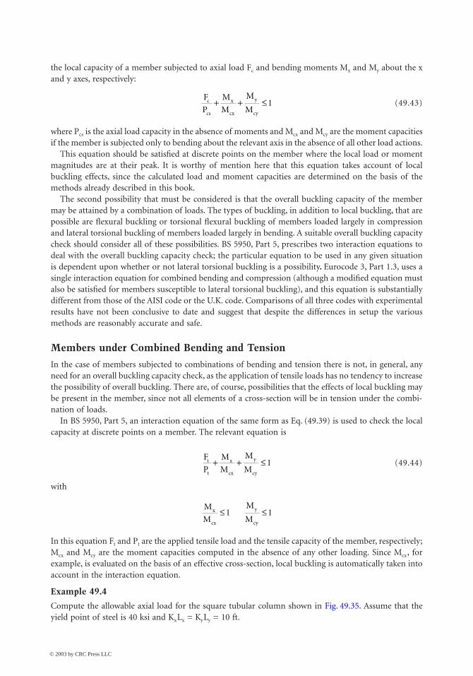
Cold Formed Steel Structures 49-37
the local capacity of a member subjected to axial load Fc and bending moments Mx and My about the xand y axes, respectively:
(49.43)
where Pcs is the axial load capacity in the absence of moments and Mcx and Mcy are the moment capacitiesif the member is subjected only to bending about the relevant axis in the absence of all other load actions.
This equation should be satisfied at discrete points on the member where the local load or momentmagnitudes are at their peak. It is worthy of mention here that this equation takes account of localbuckling effects, since the calculated load and moment capacities are determined on the basis of themethods already described in this book.
The second possibility that must be considered is that the overall buckling capacity of the membermay be attained by a combination of loads. The types of buckling, in addition to local buckling, that arepossible are flexural buckling or torsional flexural buckling of members loaded largely in compressionand lateral torsional buckling of members loaded largely in bending. A suitable overall buckling capacitycheck should consider all of these possibilities. BS 5950, Part 5, prescribes two interaction equations todeal with the overall buckling capacity check; the particular equation to be used in any given situationis dependent upon whether or not lateral torsional buckling is a possibility. Eurocode 3, Part 1.3, uses asingle interaction equation for combined bending and compression (although a modified equation mustalso be satisfied for members susceptible to lateral torsional buckling), and this equation is substantiallydifferent from those of the AISI code or the U.K. code. Comparisons of all three codes with experimentalresults have not been conclusive to date and suggest that despite the differences in setup the variousmethods are reasonably accurate and safe.
Members under Combined Bending and Tension
In the case of members subjected to combinations of bending and tension there is not, in general, anyneed for an overall buckling capacity check, as the application of tensile loads has no tendency to increasethe possibility of overall buckling. There are, of course, possibilities that the effects of local buckling maybe present in the member, since not all elements of a cross-section will be in tension under the combi-nation of loads.
In BS 5950, Part 5, an interaction equation of the same form as Eq. (49.39) is used to check the localcapacity at discrete points on a member. The relevant equation is
(49.44)
with
In this equation Ft and Pt are the applied tensile load and the tensile capacity of the member, respectively;Mcx and Mcy are the moment capacities computed in the absence of any other loading. Since Mcx, forexample, is evaluated on the basis of an effective cross-section, local buckling is automatically taken intoaccount in the interaction equation.
Example 49.4
Compute the allowable axial load for the square tubular column shown in Fig. 49.35. Assume that theyield point of steel is 40 ksi and KxLx = KyLy = 10 ft.
F
P
M
M
M
Mc
cs
x
cx
y
cy
+ + £ 1
F
P
M
M
M
Mt
t
x
cx
y
cy
+ + £ 1
M
M
M
Mx
cx
y
cy
£ £1 1
© 2003 by CRC Press LLC

49-38 The Civil Engineering Handbook, Second Edition
Solution:The solution given below is based on the AISI code.Since the square tube is a doubly symmetric closed section, it will not be subject to torsional flexuralbuckling.
Sectional Properties of Full Section
Nominal Buckling Stress, Fn — The elastic flexural buckling stress, Fe, is computed as follows:
Since Fe > Fy/2 = 20 ksi,
Effective Area, Aeff — Because the given square tube is composed of four stiffened elements, the effectivewidth of stiffened elements subjected to uniform compression can be computed by using k = 4.0:
FIGURE 49.35 Example 49.4.
R = 3/16"
P
Ix = Iy = 0.00024 in.
R = 3/16"t = 0.105"t = 0.105"
xx
yx−
y−
y
xx
y
y
10.00"
10.00"
0.2925"0.2925"
0.2925"
0.2925"
w = 9.415"
w = 9.415"10"
P x− = y− = 0.1373 in.
A = 0.0396 in.2
(Negligible)
b R t in
A in
I Ix y
= - +( ) = - +( ) =
= ¥ +( ) =
= = ( ) ( ) + -ÊËÁ
ˆ¯
È
ÎÍÍ
˘
˚˙˙
+ ( ) -
10 00 2 10 00 2 0 1875 0 105 9 415
4 9 415 0 105 0 0396 4 113
2 0 1051
129 415 9 415 5
0 105
24 0 0396 5 0 0 1373
2
32
. . . . . .
. . . . .
. . ..
. . .(( )
=
= = = =
2
466 75
66 75
4 1134 029
. .
.
.. .
in
r rI
Ainx y
x
KL
rO K
FE
KL rksie
= ¥ = <
=( )
= ( )( )
=
10 12
4 02929 78 200
29 500
29 78328 3
2
2
2
2
.. . .
,
..
p p
F F F F
ksi
n y y e= -( )= - ¥( )[ ]=
1 4
40 1 40 4 328 3
38 78
.
.
© 2003 by CRC Press LLC

Cold Formed Steel Structures 49-39
Since ,
The effective area is (4.73 ¥ 0.105 + 0.0396) = 2.145 in.2
Nominal and Allowable Loads:
The use of Wc = 1.92 is because the section is not fully effective.
49.5 Connections for Cold-Formed Steelwork
All of the connection methods applicable to hot-rolled sections, such as bolting and welding, are alsoapplicable to cold-formed steel sections at the thicker end of the range. In the case of thinner cold-formedsteel sections an extremely wide assortment of proprietary fasteners and fastening techniques exists. Thiswide range raises problems in setting realistic and reliable approaches to defining connection strength,and evaluation of the connection properties on the basis of testing is generally undertaken.
Types of Fastener
Davies (Rhodes, 1991) listed fasteners in three main groupings, as shown in Table 49.2The selection of the most suitable type of fastener for a given application is governed by several factors,
notably:
1. load-bearing requirements viz. strength, stiffness, and deformation capacity2. economic requirements viz. number of fasteners required, cost of labor and materials, skill required
in fabrication, design life, maintenance, and ability to be dismantled
TABLE 49.2 Typical Applications of Different Types of Fastener
Thin to ThinThin to Thick or
Thin to Hot Rolled Thick to Thick or
Thick to Hot Rolled
Self-drilling self-tapping screwsBlind rivetsSingle-flare V weldsSpot weldsLock seaming
Self-drilling self-tapping screwsFired pinsBoltsArc puddle welds
BoltsArc welds
b t
pE
b tksi
f
p
cr
cr
= =
=-( ) ( )
=
= =
9 415 0 105 89 67
4
12 1
113 26
40
13 261 737
2
2 2
. . .
.
..max
pn
f
pcr
max .> 0 63755
b bp
f
p
f
in
effcr cr= -
È
ÎÍÍ
˘
˚˙˙
=
max max
.
. .
1 0 22
4 73
P A F kips
P P kips
n e n
a n c
= = ( )( ) =
= = =
2 145 38 78 83 18
83 18 1 92 43 32
. . .
. . .W
© 2003 by CRC Press LLC

49-40 The Civil Engineering Handbook, Second Edition
3. durability viz. resistance to aggressive environments4. watertightness5. appearance
Although structural engineers tend to be primarily concerned with the most economical way of meetingthe load-bearing requirements, in many applications other factors may be equally important.
Bolts
The use of bolts to connect cold-formed steel components follows a practice similar to that of hot-rolledconstruction; however, because of the thinness of the material and the relatively small size of the com-ponents, the main design considerations tend to be end distance and bearing. With regard to bearing itis worth noting that hot-rolled steel design codes tend to have significantly different design treatmentsof this than cold-formed steel codes. This may be partially due to the different behavior of thin material,but is mainly due to the adoption of different philosophies by the writers of cold-formed steel and hot-rolled steel codes. In British codes in particular, the cold-formed steel rules are based on strength design,while the hot-rolled steel rules are based on limiting slip. Table 49.3, from Davies (Rhodes, 1991), showsthe comparison between permissible bearing stresses in bolted connections according to various codes.
Self-Tapping Screws
Self-tapping screws fall into two distinct types, depending on whether or not they require a predrilledhole. Conventional self-tapping screws require a predrilled hole and fall into a number of subgroups,depending on the type of thread, head, and washer. Self-drilling self-tapping screws drill their own holeand form their own thread in a single operation. There are two basic types, depending on the thicknessof the base material. Both of these screws are usually combined with washers that serve to increase theload-bearing capacity or sealing ability.
Blind Rivets
Blind rivets are normally used for fastening two thin sheets of material together when access is availablefrom one side only. These are installed in a single operation, for example, by pulling a mandrel thatforms a head on the blind side of the rivet and expands the rivet shank. Fastening is completed whenthe mandrel either pulls through or breaks off. This type of fastener generally requires strength consid-erably in excess of the sheet material to minimize possibilities of brittle failure.
TABLE 49.3 Permissible Bearing Stress in Bolted Connections
Code Bearing Stress Basis
Addendum 1 (April 1975) to BS 449BS 5950, Part 1 (hot-rolled)BS 5950, Part 5 (cold formed)a
(a) t £ 1 mm(b) 1 mm £ t £ 3 mm(c) 3 mm £ t £ 8 mm
AISI specification (August 1986)(a) with washers(b) without washers
European recommendations(a) t £ 1 mm(b) 3 mm £ t £ 6mm
Eurocode 3, Part 1.3
1.4Us
0.64(U s + Ys)
2.1Ys
(1.65 + 0.45t)Ys
3.0Ys
1.35Us to 1.50Us
1.00Us to 1.35Us
2.1Ys
4.3Ys
2.5 Us
Permissible stressLimit stateLimit state
Permissible stress
Limit state
Limit state
Note: Ys = yield stress of fastened sheet, Us = ultimate stress of fastened sheet.a Values in BS 5950, Part 5, are reduced by 25% unless two washers are used.
© 2003 by CRC Press LLC

Cold Formed Steel Structures 49-41
Fired Pins
These pins, as the name suggests, are fired through thin material into thicker base material to form aconnection. Two different methods of firing the pins are commonly used: powder actuation and pneu-matic actuation. In the former the pins are fired from a tool that contains an explosive cartridge, and inthe latter compressed air is used as the firing agent. Fired pins generally provide a very tight grip and avery good sealing capability.
Spot Welds
Electrical resistance spot welds are a widely used method of connecting thin sheets. In the United Kingdomthese are governed by BS 1140, General Requirements for Spot Welding of Light Assemblies in Mild Steel,and recommendations regarding weld sizes and capacities are provided in BS 5950, Part 5, and the AISIspecification. Further information on loads in resistance spot welds has been given by Baehre andBerggren (1973).
Arc Welds
Conventional fillet and butt welds are applicable to cold-formed steel sections if the material is relativelythick, and in such cases design considerations are the same as those for hot-rolled sections. In the caseof thinner material a wide range of special weld types are used in, but not outside of, the U.S. . Guidanceon making these special welds has been given by Blodgett (1978). Expressions for the evaluation of theultimate loads for various types of these connections are available from a large testing and analysisprogram carried out by Peköz and McGuire (1979).
Clinch Joints and Rosette Joints
A relatively new method of connecting components together is mechanical clinching. This technique wasoriginally developed for use in the automobile industry, but in recent years has found a number ofapplications in cold-formed steel construction and has been the subject of substantial research (e.g.,Davies et al., 1996). In making clinched joints, hydraulic tools are used as a punch-and-die set that shearsand deforms the material to be connected to produce a connection in which material from one sheetbears on material from another, and the connection is dependent only on the parent material.
Another type of connection that is uniquely suited to light-gauge material and requires no additionalfixings is the Rosette joint. In this joint holes are punched into the two adjoining strips of material atthe connection point, with one of the sheets having a reduced diameter to form a collar. In the joiningprocess the collar is snapped into the hole in the adjoining strip, and the Rosette tool penetrates the holeand collar, expands, and is pulled back to crimp the collar to the opposite side of the hole, thus producinga secure connection. Details of Rosette joints may be found, for example, in Makelainen et al. (1999).
Assemblies of Fasteners
The available information on the the behavior of assemblies of fasteners in light-gauge steelwork suggeststhat the performance of such assemblies is not in any way inferior to that of similar connection assembliesin hot-rolled members. Connections in cold-formed members, however, do tend to be more flexible andductile than in hot-rolled members, and herein lies a bonus that is well appreciated in some areas ofcold-formed steel usage. The ductility afforded by such connections can provide the “plastic plateau”behavior that often occurs in hot-rolled sections, thus allowing redistribution of moments in the postyieldrange. A prime example of this in the United Kingdom is the wide use of “sleeves” in purlin design. Thesesleeves are used to connect purlins in a semirigid fashion, which produces a moment distribution closeto the ideal at the point of failure.
49.6 Sheeting and Decking
There has been in the recent past a substantial increase in the usage of profiled sheeting and decking,and this has been accompanied by a corresponding development of the design principles applicable to
© 2003 by CRC Press LLC

49-42 The Civil Engineering Handbook, Second Edition
this type of construction. Although only a few years ago 3-in. corrugated profiles or simple trapezoidalprofiles were the norm, today there is a multiplicity of different shapes available. Profiles can be obtainedin a wide variety of colors, surface coatings, etc., with a life to first maintenance of up to 25 years. Therehave been a large number of developments of structural improvements, involving the use of thinnermaterial, of increased yield strength in highly stiffened profiles. It is most probable, however, that in thisarea improvements in aesthetics, utility, and durability outweigh the structural improvements.
Profiles for Roof Sheeting
Cold roof construction is the term applied to construction in which profiled steel sheeting is used as theouter waterproof skin of a roof, with insulation placed inside this skin. It is important that the skinshould provide the optimum resistance to moisture penetration, and the side laps should occur near thecrests of the corrugations. With modern fasteners, e.g., self-drilling self-tapping screws with neoprenewashers, it is quite permissible to fix the sheeting to the roof purlins through the troughs. These fastenerssatisfactorily prevent moisture penetration, while providing various structural benefits in the fixityprovided to the purlins over through-crest fixings.
Modern profiles can be grouped into four main types, as illustrated in Fig. 49.36. For the trapezoidalprofile shown in Fig. 49.36a, it is found that to obtain the most economic use of material for a givenspan and loading, using standard analysis procedures, the thickness of material and web slope angle thatresult are impractical, the thickness usually being very small and the web slope very shallow. Fairly widevariations in the trapezoidal geometry result in relatively small variations in the economy, and the designof this type of sheeting is generally governed by practical considerations. In the profile of Fig. 49.36b,again a fairly widely used shape of profile, the trapezoidal shape is altered to incorporate intermediatestiffeners in the lower flanges. In order to reduce or eliminate the requirement to penetrate the skin withfasteners, concealed fixed or standing seam sheeting has been developed over a number of years(Fig. 49.36c and d). The fixing in these systems is generally by means of clips that connect mechanicallyto the sheeting and by screws to the purlin, with the mechanical connections to the sheeting oftenincorporated in the standing seam, eliminating penetration of the sheeting. In this type of system thepurlin–sheeting connections are less useful in providing stability to the purlin than the more direct screwfixings, and may necessitate close consideration of purlin design in such circumstances.
Profiles for Roof Decking
Profiled steel decking, supporting a built-up finish, including insulation and waterproofing, is oftentermed warm roof construction. In this type of construction there is a tendency toward longer spans, morecomplex profiles, and the use of higher strength steels. A typical profile resulting from these tendenciesis shown in Fig. 49.37. The profile depth is of the order of 4 in., and the material yield strength is of the
FIGURE 49.36 Typical roof sheeting profiles.
(a) (b)
(c) (d)
© 2003 by CRC Press LLC

Cold Formed Steel Structures 49-43
order of 50 ksi. These profiles are suitable for spans up to 30 ft and can thus eliminate the need forpurlins. In general, stiffeners are rolled into both the flanges and the webs, as flanges and webs are slenderand require stiffeners for efficiency.
There are nowadays a large number of different design specifications dealing with roof decking. InEurope calculation procedures for complex shapes, as shown in Fig. 49.37, have been developed in Swedenfor incorporation into the Swedish code of practice (Höglund, 1980), and these procedures form thebasis of the European recommendations (ECCS, 1983), as well as the national standards of some Europeancountries, for example, DIN 18807 (1987). These procedures have been verified by a very substantialnumber of tests (Baehre and Fick, 1982).
Wall Coverings
Wall cladding carries significant wind loading and must satisfy structural considerations. However, theaesthetic considerations here are so strong, since the appearance of a building is very substantiallydependent on the sheeting, that aesthetics are often the primary consideration. Typical wall claddingprofiles are shown in Fig. 49.38. By virtue of the variety of profiles available, the wide range of coatingsand colors, and the possibility of orienting the cladding in any desired direction, there is substantial scopefor imagination and artistry in the use of modern wall coverings in building design.
Composite Panels
Composite panels, having outer faces of thin steel (or other material such as aluminum) and an internalcore of foamed plastic (such as polyurethane or expanded polystyrene), are now widely used in construc-tion (Fig. 49.39). The design criteria for composite panels are complex and are not discussed here.
FIGURE 49.37 Typical long-span decking profiles.
FIGURE 49.38 Typical wall cladding profiles.
FIGURE 49.39 Typical sandwich panels: (a) panel with flat faces, (b) panel with profiled faces, (c) panel with profiledface.
= 100 mm
(a)
(b)
(c)
© 2003 by CRC Press LLC

49-44 The Civil Engineering Handbook, Second Edition
However, this type of construction must be mentioned because of its current growth and future poten-tialities. Foam-filled composite construction utilizes the favorable attributes of skin and core materialsin combination. The core connects the metal skins, while ensuring that they are kept a distance apart toprovide flexural capacity for the panel, and also provides a degree of resistance to local buckling of theskins. The skins protect the core from accidental damage and from the elements. Foam-filled panelscombine a high load-carrying capacity with low weight, attractive appearance, and other made-to-orderattributes, such as an extremely high thermal insulation capacity, to provide very good solutions to avariety of construction problems.
49.7 Storage Racking
The term storage racking covers an extremely wide range of products that have as their purpose the storageof material in a secure and easily accessible manner. Storage racking systems range from small shelvingsystems to extremely large rack-clad buildings. The components used in storage racking are largely ofcold-formed steel, and the storage racking industry is one of the major users of cold-formed steel.
The forerunners of the modern storage structures were slotted-angle products first introduced in the1930s. These consisted of cold-formed angle sections with perforations to provide a means whereby thedesigner could utilize the simplicity and flexibility of connections thus permitted to produce storagesystems in a variety of shapes and configurations. By this means simple shelving could be provided forwarehouses of any size. From these beginnings natural evolution lead to the present-day situation. It wasfound that for many systems bolted connections could be beneficially replaced by clips or other propri-etory connections, and a wide variety of alternative connection methods were developed for differentsystems. Although perforated angles had much in their favor for some purposes, particularly for smallerstorage systems, the requirements for bracing in these torsionally weak members meant that for manypurposes other shapes of cross-sections were superior. Nowadays slotted angles are still widely used forshelving systems, but in larger storage racking systems other perforated members, generally monosym-metric, are used as columns, while normally unperforated members are used as beams.
Components
Beams
In pallet racking the most common types of beams used areboxed beams, made from two interlocking lipped channels(Fig. 49.40a), and open-section beams (Fig. 49.40b), whichmay be stepped to receive the edge of a shelf (Fig. 49.40c).The boxed beam is generally more structurally efficient thanthe open beam, but for lighter loads the economical aspectscan favor the open section. Over the normal range of spansused in storage racking the limiting factor for the beamsused is most often the bending capacity. The most commonconfiguration of beam loading is that shown in Fig. 49.41with two pallets in place.
Uprights
Figure 49.42 shows typical perforated upright profiles usedin storage racking at the present time. These are, in the main,developments from the simple lipped channel section. Thedevelopments generally involve the addition of more bends,which can be used to assist the attachment of bracing mem-bers, as well as to enhance the structural capacity of theuprights. The bracing members, often of channel section,
FIGURE 49.40 Typical beam profiles: (a) box,(b), open, (c) stepped open.
FIGURE 49.41 Two-pallet beam loading.
(a)
(b)
(c)
Shelf
© 2003 by CRC Press LLC

Cold Formed Steel Structures 49-45
connect through the rear circular holes of the section, while the beams are connected, via beam endconnectors, through the perforations on the front face. The loads carried by the uprights are spread intothe floor through base plates. These are normally thin plates, of about 3 mm thick, which are bolted tothe upright and to the floor.
Beam End Connectors
The beams used in storage racking are generally connected to the uprights via beam end connectors.These are generally made from hot-rolled material and are welded to the ends of the beam to provide ameans of connecting the beam to the upright at any of a large number of positions through the perfo-rations in the uprights. The connectors have hooks that fit through the upright perforations to providea semirigid connection between the beam and upright. In evaluation of the behavior of beams anduprights the connection behavior is very important. The moment rotation behavior of beam end con-nectors is normally obtained on the basis of testing, and the strength and stiffness values so obtained areused in design analysis of the structure.
Design Codes of Practice
In Europe storage racking systems are generally considered to lie outside the scope of the normal codesof practice for structural design. This is largely because of the presence of perforations in uprights andother components. In the United Kingdom the Storage Equipment Manufacturers Association (SEMA)devised and published its own code of practice (SEMA, 1980). In Europe the Federation Europeene de laManutention (FEM) has in recent years prepared a new code of practice (FEM, 1986) that is at completionstage and will have currency throughout Europe, eventually superseding the SEMA code in the UnitedKingdom and similar codes in other countries. This code is written in limit state to be compatible withEurocode 3.
Defining Terms
Beam — A straight or curved structural member, primarily supporting loads applied at right angles tothe longitudinal axis.
Beam-column — A beam that also functions to transmit compressive axial force.Bifurcation — A term relating to the load-deflection behavior of a perfectly straight and perfectly
centered compression element at critical load.Blind rivet — Mechanical fastener capable of joining workpieces together where access to the assembly
is limited to one side only.Buckle — To kink, wrinkle, bulge, or otherwise lose original shape as a result of elastic or inelastic strain.
FIGURE 49.42 Typical upright profiles.
Standard
Load
s to
230
00 k
g (5
0000
lb)
Medium
Heavy-duty Extra heavy-duty
Load
s to
130
00 k
g (3
0000
lb)
Load
s to
800
0 kg
(18
000
lb)
Load
s to
180
00 k
g (4
0000
lb)
© 2003 by CRC Press LLC

49-46 The Civil Engineering Handbook, Second Edition
Buckling load — The load at which a compressed element, member, or frame collapses in service orbuckles in a loading test.
Cladding — Profiled sheet for walls.Cold-formed steel structural members — Shapes that are manufactured by press-braking blanks
sheared from sheets, cut length of coils or plates, or by roll forming cold- or hot-rolled coils orsheets.
Composite slab — Floor in which the structural bearing capacity is formed by the cooperation ofconcrete and floor decking (as reinforcement).
Critical load — The load at which bifurcation occurs, as determined by a theoretical stability analysis.Effective length — The equivalent or effective length that, in the buckling formula for a hinged-end
column, results in the same elastic critical load as that for the framed member or othercompression element under consideration at its theoretical critical load.
Effective width — Reduced width of a compression element in a flexure or compression memberscomputed to account for local buckling when the flat width-to-thickness ratio exceeds a certainlimit.
Flat width — Width of the straight portion of the element, excluding the bent portion of the section.Flat width-to-thickness ratio — Ratio of the flat width of an element to its thickness.Flexural buckling — Buckling of a column due to flexure.Initial imperfection — Deviation from perfect geometry, for example, initial crookedness of a member
or initial out-of-flatness of a plate.Limit state — Condition beyond which a structure would cease to be fit for its intended use.Local buckling — Buckling of the walls of elements of a section characterized by a formation of waves
or ripples along the member. It modifies the capacity of cross-sections.Multiple stiffened element — An element stiffened between webs, or between a web and a stiffened
edge, by means of intermediate stiffeners parallel to the direction of stress.Residual stress — The stresses that exist in an unloaded member after it has been formed into a finished
product.Safety factor — A ratio of the stress (or strength) at incipient failure to the computed stress (or strength)
at design load.Self-drilling screw — Screw that drills its own hole and forms its mating thread in one operation.Self-tapping screw — Screw that taps a counterthread in a prepared hole.Sheeting — Profiled sheet for floors, roofs, or walls.Stiffened or partially stiffened element — A flat compression element in which both edges parallel
to the direction of stress are stiffened either by a web, flange, stiffening lip, or intermediatestiffener.
Tension field action — Postbuckling behavior of a plate girder panel under shear force, during whichdiagonal compressive stresses cause the web to form diagonal waves.
Thickness — Thickness of base steel in cold-formed sections.Torsional buckling — Buckling of a column by twisting.Torsional flexural buckling — A mode of buckling in which compression members can bend and twist
simultaneously. This type of buckling mode is critical, in particular when the shear center ofthe section does not coincide with the centroid.
Unstiffened element — A flat compression element that is stiffened at one of the two edges parallel tothe direction of stress.
Web crippling — Failure mode of the web of a beam caused by the combination of a bending momentand a concentrated load.
Yield point — The maximum stress recorded in a tensile or compressive test of steel specimen prior toentering the plastic range.
Yield strength — In a tension or compression test, the stress at which there is a specified amount ofmeasured deviation from an extension of the initial linear stress–strain plot.
© 2003 by CRC Press LLC

Cold Formed Steel Structures 49-47
References
AISI, Specification for the Design of Cold-Formed Steel Structural Members, American Iron and SteelInstitute, 1986.
AISI, Load and Resistance Factor Design (LRFD) Specification for Cold-Formed Steel Structural Mem-bers, American Iron and Steel Institute, 1991.
Allen, H.G. and Bulson, P.S., Background to Buckling, McGraw-Hill Book Co., New York, 1980.Baehre, R. and Berggren, L., Joints in Sheet Metal Panels, Document D8, National Swedish Building
Research, 1973.Baehre, R. and Fick, K., Berechnung und Bemessung von Trapezprofilen-mit erläuterungen zur DIN
18807. Berichte der Versuchsanstalt fur Stahl. Holz und Stein, Universität Fridericiana Karlsruhe,Germany, 1982.
Blodgett, O.W., Report on Proposed Standards for Sheet Steel Structural Welding, paper presented at 4thInternational Speciality Conference on Cold-Formed Steel Structures, University of Missouri–Rolla,June 1978.
British Standards Institution, Specification for the Use of Cold Formed Steel in Building, Addendum 1,1975, to BS 449 (1969).
British Standards Institution, Structural Use of Steelwork in Building, BS 5950, Part 1, 1985, and Part 5,1987.
Canadian Standards Association, Cold-Formed Steel Structural Members, CAN3-S136-M89, 1989.Chajes, A. and Winter, G., Torsional-flexural buckling of thin-walled members, ASCE J. Struct. Div., 91, 1965.Davies, R., Pedreschi, R., and Sinha, B.P., The Shear Behaviour of Press Joining in Cold-Formed Steel
Structures, in Thin-Walled Structures, Vol. 23, No. 3, 1996, p. 153.Desmond, T.P., Pekoz, T., and Winter, G., Edge stiffeners for thin-walled members, J. Struct. Div. ASCE,
107(ST2), 1981.DIN 18807, Trapezprofile im Hochbau (Trapezoidal Profiled Sheeting in Building), Deutsche Norm
(German Standard), June 1987.ECCS, European Recommendations for the Design of Profiled Sheeting, European Convention for Con-
structional Steelwork, ECCS-TC7-1983, 1983.Eurocode 3, Design of Steel Structures, draft issue 2, November 1989.FEM, Recommendations for the Design of Steel Static Pallet Racking, Federation Europeene de la
Manutention, draft edition, 1986.Hancock, G.J., Cold-Formed Steel Structures, Australian Institute of Steel Construction, Sydney, 1988.Hetrakul, N. and Yu, W.W., Cold formed steel I-beams subjected to combined bending and web crippling,
in Thin-Walled Structures, Rhodes, J. and Walker, A.C., Eds., Granada Publishing, 1980.Hofmeyer, H. et al., FE Models for Sheeting under Interaction Load, paper presented at 15th International
Specialty Conference on Cold-Formed Steel Structures, St. Louis, MO, October 2000. Höglund, T., Design of Trapezoidal Sheeting Provided with Stiffeners in the Flanges and Webs, Document
D28, Swedish Council for Building Research, 1980.Makelainen, P. et al., Static and Cyclic Shear Behaviour Analysis of the Rosette-Joint, paper presented at
ICSAS ’99 Lightweight Steel and Aluminium Structures, Espoo, Finland, 1999. Megon, T.H.G., Analysis of Thin-Walled Members. Intertext, 1975.Metal Roof Deck Association, Code of Design and Technical Requirements for Light Gauge Metal Roof
Decks, Metal Roof Deck Association, London, 1970.Murray, N.W., Introduction to the Theory of Thin Walled Structures, Oxford Press, Oxford, 1984.National Swedish Committee on Regulations for Steel Structures, Swedish Code for High-Gauge Metal Struc-
tures, National Swedish Committee on Regulations for Steel Structures, 1982 (English translation).Peköz, T. and Celebi, N., Torsional-flexural buckling of thin-walled sections under eccentric load, Cornell
Univ. Eng. Res. Bull., 69, 1, 1969.Peköz, T. and McGuire, W., Welding of Sheet Steel, Private Report to AISI, Cornell University, Ithaca,
NY, January 1979.
© 2003 by CRC Press LLC
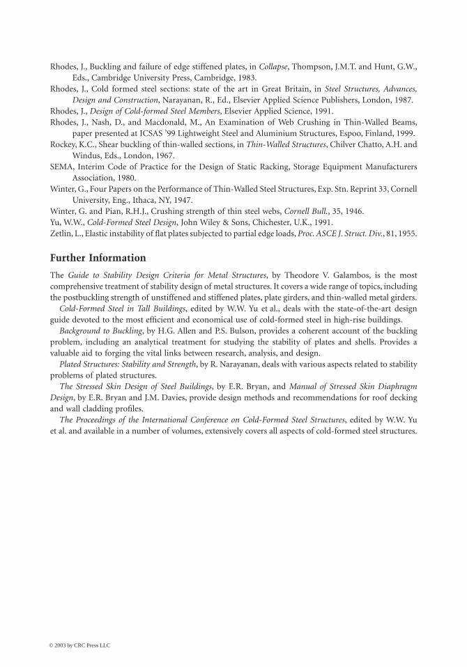
49-48 The Civil Engineering Handbook, Second Edition
Rhodes, J., Buckling and failure of edge stiffened plates, in Collapse, Thompson, J.M.T. and Hunt, G.W.,Eds., Cambridge University Press, Cambridge, 1983.
Rhodes, J., Cold formed steel sections: state of the art in Great Britain, in Steel Structures, Advances,Design and Construction, Narayanan, R., Ed., Elsevier Applied Science Publishers, London, 1987.
Rhodes, J., Design of Cold-formed Steel Members, Elsevier Applied Science, 1991.Rhodes, J., Nash, D., and Macdonald, M., An Examination of Web Crushing in Thin-Walled Beams,
paper presented at ICSAS ’99 Lightweight Steel and Aluminium Structures, Espoo, Finland, 1999. Rockey, K.C., Shear buckling of thin-walled sections, in Thin-Walled Structures, Chilver Chatto, A.H. and
Windus, Eds., London, 1967.SEMA, Interim Code of Practice for the Design of Static Racking, Storage Equipment Manufacturers
Association, 1980.Winter, G., Four Papers on the Performance of Thin-Walled Steel Structures, Exp. Stn. Reprint 33, Cornell
University, Eng., Ithaca, NY, 1947.Winter, G. and Pian, R.H.J., Crushing strength of thin steel webs, Cornell Bull., 35, 1946.Yu, W.W., Cold-Formed Steel Design, John Wiley & Sons, Chichester, U.K., 1991.Zetlin, L., Elastic instability of flat plates subjected to partial edge loads, Proc. ASCE J. Struct. Div., 81, 1955.
Further Information
The Guide to Stability Design Criteria for Metal Structures, by Theodore V. Galambos, is the mostcomprehensive treatment of stability design of metal structures. It covers a wide range of topics, includingthe postbuckling strength of unstiffened and stiffened plates, plate girders, and thin-walled metal girders.
Cold-Formed Steel in Tall Buildings, edited by W.W. Yu et al., deals with the state-of-the-art designguide devoted to the most efficient and economical use of cold-formed steel in high-rise buildings.
Background to Buckling, by H.G. Allen and P.S. Bulson, provides a coherent account of the bucklingproblem, including an analytical treatment for studying the stability of plates and shells. Provides avaluable aid to forging the vital links between research, analysis, and design.
Plated Structures: Stability and Strength, by R. Narayanan, deals with various aspects related to stabilityproblems of plated structures.
The Stressed Skin Design of Steel Buildings, by E.R. Bryan, and Manual of Stressed Skin DiaphragmDesign, by E.R. Bryan and J.M. Davies, provide design methods and recommendations for roof deckingand wall cladding profiles.
The Proceedings of the International Conference on Cold-Formed Steel Structures, edited by W.W. Yuet al. and available in a number of volumes, extensively covers all aspects of cold-formed steel structures.
© 2003 by CRC Press LLC