
COKE DRUM DESIGN – LONGER LIFE THROUGH INNOVATION...
10
T9023a COKE DRUM DESIGN – LONGER LIFE THROUGH INNOVATION Charles J. (Chuck) Pieper, Lestle R. (Ron) Shockley, and Coby W. Stewart Chicago Bridge & Iron Company 1501 North Division Street Plainfield, Illinois 60544-8984 www.chicagobridge.com Prepared for presentation at the AIChE 2000 Spring national Meeting, March 5-9 2000 © C. J. Pieper, L. R. Shockley, and C. W. Stewart, Chicago Bridge & Iron Company December 1999 AIChE Shall Not Be Responsible For Statements or Opinions Contained in Papers or printed In Its Publications. ABSTRACT Coke drums tend to suffer from a "bulging" phenomenon due to the cyclic nature of their service. This phenomenon occurs in the lower portion or the “quench zone” of the vessel. The bulges typically are located near the circumferential weld seams joining the cylindrical shell courses. As the number of thermal cycles increase, the bulges grow larger and cause cracking in the vessel shell. The cracking also increases in length, depth and number of cracks as cycle frequency increases. At some point in operation, the cracking must be repaired, the shell sections replaced or the entire vessel replaced for continued safe operation. Industry studies of operating coking units, which included thermal and mechanical stress analysis, have determined that the circumferential weld seams act as a stiffener during the water quench cycle, causing the shell to distort a short distance above and/or below the weld seam. Several methods to minimize this phenomenon from occurring have been proposed by those in the coking industry, including vessel manufacturers, with only incremental success. This paper describes the bulging phenomena, normally accepted solutions, and a revolutionary method developed by Chicago Bridge & Iron Company to eliminate a primary contributing factor causing the bulging/cracking phenomena. INTRODUCTION Industrial petroleum coke is a solid coal-like substance primarily used as a fuel or for the production of anodes, electrodes, graphite or similar carbon based products. Petroleum coke is produced by the “delayed-coking” process. A batch process involving the superheating of heavy residual feed stocks and introducing them into an insulated vertically oriented cylindrical pressure vessel, commonly known as a “coke drum”. Vapors are then drawn off and further refined into various petroleum byproducts, leaving
Transcript of COKE DRUM DESIGN – LONGER LIFE THROUGH INNOVATION...

T9023a
COKE DRUM DESIGN – LONGER LIFE THROUGH INNOVATION
Charles J. (Chuck) Pieper, Lestle R. (Ron) Shockley, and Coby W. Stewart
Chicago Bridge & Iron Company1501 North Division Street
Plainfield, Illinois 60544-8984www.chicagobridge.com
Prepared for presentation at the AIChE 2000 Spring national Meeting, March 5-9 2000
© C. J. Pieper, L. R. Shockley, and C. W. Stewart, Chicago Bridge & Iron Company
December 1999
AIChE Shall Not Be Responsible For Statements or Opinions Contained in Papers or printed In ItsPublications.
ABSTRACT
Coke drums tend to suffer from a "bulging" phenomenon due to the cyclic nature of their service. Thisphenomenon occurs in the lower portion or the “quench zone” of the vessel. The bulges typically arelocated near the circumferential weld seams joining the cylindrical shell courses. As the number ofthermal cycles increase, the bulges grow larger and cause cracking in the vessel shell. The cracking alsoincreases in length, depth and number of cracks as cycle frequency increases. At some point inoperation, the cracking must be repaired, the shell sections replaced or the entire vessel replaced forcontinued safe operation.
Industry studies of operating coking units, which included thermal and mechanical stress analysis, havedetermined that the circumferential weld seams act as a stiffener during the water quench cycle, causingthe shell to distort a short distance above and/or below the weld seam. Several methods to minimize thisphenomenon from occurring have been proposed by those in the coking industry, including vesselmanufacturers, with only incremental success. This paper describes the bulging phenomena, normallyaccepted solutions, and a revolutionary method developed by Chicago Bridge & Iron Company toeliminate a primary contributing factor causing the bulging/cracking phenomena.
INTRODUCTION
Industrial petroleum coke is a solid coal-like substance primarily used as a fuel or for the production ofanodes, electrodes, graphite or similar carbon based products. Petroleum coke is produced by the“delayed-coking” process. A batch process involving the superheating of heavy residual feed stocks andintroducing them into an insulated vertically oriented cylindrical pressure vessel, commonly known as a“coke drum”. Vapors are then drawn off and further refined into various petroleum byproducts, leaving

T9023a
behind a high-density hydrocarbon residue referred to as petroleum coke. The residue is then waterquenched to allow the removal of the coke product after the vessel has been depressurized and the cokecooled to the point it will not self ignite when exposed to air.
As part of the delayed coking process, coke drums undergo severe thermal and pressure cycling as thevessel is filled with hot product and subsequently water quenched after coke formation, see Fig.1.
The severe heating and quenching rates of the process causes the useful life of coke drums to beshortened vs. that of other pressure vessels operating in non-cyclic conditions. In addition, coke drumstypically experience significant down time during their useful life to make needed repairs or partial shellreplacements due to the damage caused by the service conditions.
To extend useful life and reduce down time, coke drums which were constructed from mild steel in theearly days have in recent years been constructed from low alloys such as Carbon-1/2 Moly, 1 Chrome-1/2 Moly and most recently 2 ¼ Cr – 1 Mo or even higher alloys. With the exception of the 2 ¼ Cr andhigher alloyed drums, coke drums manufactured with these materials have all failed in time. Cokedrums manufactured from the 2 ¼ Cr and higher alloy materials have been in service only a few yearsand have not yet endured enough cycles to demonstrate improved reliability. Most modern coke drumsare clad with type 410S or 405 stainless steel for resistance to corrosion caused by the high sulfurcontent in the feedstock. Welding filler metals are normally chosen based on the type of backing andclad (if any) as specified by the final owner/user.
It is the thermal cycling that tends to be the root cause of the bulging and eventual cracking experiencedin most applications. Depending on the operating parameters, type of coke produced, feedstock andother variables, the cycle time of a given unit can be from as little as 14 hours (or less) to more than 36hours. Industry recognizes that the shorter and more severe the cycle the sooner and more pronounced
T9023a
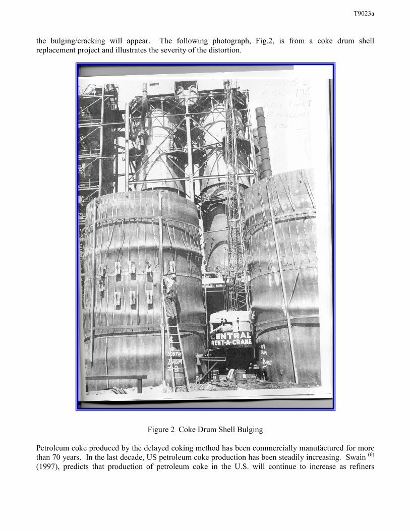
the bulging/cracking will appear. The following photograph, Fig.2, is from a coke drum shellreplacement project and illustrates the severity of the distortion.
Figure 2 Coke Drum Shell Bulging
Petroleum coke produced by the delayed coking method has been commercially manufactured for morethan 70 years. In the last decade, US petroleum coke production has been steadily increasing. Swain (6)
(1997), predicts that production of petroleum coke in the U.S. will continue to increase as refiners

T9023a
continue to process more lower quality crudes than in the past. To meet increased demand for cokeproduction, refiners either have to shorten the coking cycle or add coking units, or both.
DESCRIPTION OF “BULGING/CRACKING PHENOMENA”
Weil and Rapasky (1) (1958) identified radial bulging as a “reoccurring difficulty” that existed inessentially all operating coke drums of the time. Through extensive research carried out on a total ofsixteen coke drums erected between 1938 and 1958, they identified a radial growth varying from almostnegligible to as much as 0.3” per year. The rate of bulging was found to be directly attributable to the“quenching portion” of the operating cycle. They also recognized that the girth seams, due to the higheryield strength of the weld metal, tended to augment the bulging causing a “constrained balloon shape” asillustrated in Fig.3.
As a result of the restraint caused by the weld seams, the base material tends to become thin andultimately fail via through wall cracking. The bulging is most severe in the lower cylindrical portion ofthe vessel, typically the first 40 to 50 feet above the cone section. This section of the vessel experiencesthe highest quench rates during the quench cycle. Typical rolled and welded construction of coke drumswill place 4 to 5 circumferential seams in this 50 foot +/- section of the vessel, depending on the widthof plate used for each shell course.
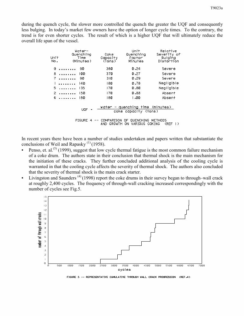
Through their studies, Weil and Rapasky (1) (1958) observed that high quenching rates produced thermalgradients in excess of 10°F per inch; lower quenching rates produced smaller gradients thus lessbulging. To measure this effect they developed a “Unit Quench Factor” (UQF) Fig.4, that is the ratio ofwater-quenching time in minutes to the coke yield per drum in tons. Utilizing the resulting data theytheorized that when the UQF is greater than 0.50 the bulging is minimal, when the UQF is greater than0.80 the bulging is all but non-existent. The UQF is directly proportional to the rate of water injection
T9023a
during the quench cycle, the slower more controlled the quench the greater the UQF and consequentlyless bulging. In today’s market few owners have the option of longer cycle times. To the contrary, thetrend is for even shorter cycles. The result of which is a higher UQF that will ultimately reduce theoverall life span of the vessel.
In recent years there have been a number of studies undertaken and papers written that substantiate theconclusions of Weil and Rapasky (1) (1958).• Penso, et. al.(5) (1999), suggest that low cycle thermal fatigue is the most common failure mechanism
of a coke drum. The authors state in their conclusion that thermal shock is the main mechanism forthe initiation of these cracks. They further concluded additional analysis of the cooling cycle iswarranted in that the cooling cycle affects the severity of thermal shock. The authors also concludedthat the severity of thermal shock is the main crack starter.
• Livingston and Saunders (4) (1998) report the coke drums in their survey began to through–wall crackat roughly 2,400 cycles. The frequency of through-wall cracking increased correspondingly with thenumber of cycles see Fig.5.

T9023a
• Antalffy, et al. (3) (1999) cites at least three additional examples of recent papers which reference thebulging phenomena. He also cites that Boswell and Ferraro (2) (1997) and others as concluding thehigh relative strength of the circumferential weld metal as compared to the lower strength of theadjacent base metal to be the cause of the bulging
It is common industry knowledge through thermal and stress analyses of operating units, that the higherstrength of the weld metal in the circumferential seams tends to have a stiffening effect which increasesstress leading to distortion and cracking. The longitudinal weld seams required to make the shellcourses are reported to be unaffected by the thermal cycling except where these seams intersect thecircumferential seams. In the bulge areas near the circumfrential seams, the longitudinal weld seams arealso affected by the thinning effect and will crack, given enough thermal cycles.
CONVENTIONAL DESIGN METHODOLOGY
The normal method of designing the shell courses of coke drums is to base the thickness of the materialon the specified design pressure. Generally the pressure is specified as varying linearly from aminimum value at the top of the vessel to a maximum at the bottom flange. Because overall vessel costis a function of weight and thickness, the tendency is to design each shell course for the design pressurespecified at the bottom of the course. As a result, there are typically step reductions in thickness fromone shell course to the next as shown in Figure 6. The resulting weld profile compounds the stiffeningeffect already present due to the higher yield strength of the weld metal, see Figure 7.

T9023a
SPECIFICATIONS INTENDED TO INCREASE VESSEL LIFE
As a result of the recent interest in improving coke drum reliability, there have been a number ofmeasures developed or proposed that are intended to mitigate the stiffening effect of the weld seams.These measures have be incorporated into numerous procurement specifications that are intended toaddress the bulging/cracking phenomena and increase vessel life. For the most part these requirementsare aimed at reducing the discontinuity effect at the circumferential weld seam. The most common ofthese specifications are as follows:
• Weld metal yield strength to be within a close percentage of base metal yield (e.g. - 0%, +10%) .• “Blend grinding” the weld profile.• Specifying higher alloy materials, i.e. 2 ¼ Cr – 1 Mo, and higher.• Requiring more nondestructive examinations and using more restrictive nondestructive examination
acceptance criteria than the construction code requires.• Maintaining a uniform shell thickness through out the vessel.• Specifying materials greater than two inches in thickness.
Though most have technical merit, the resulting improvement may only be incremental and notnecessarily practical. For example, specifying a maximum allowance of strength mismatch between theweld metal and base metal is difficult at best due to the many variables involved. The actual yieldstrength of the base metals when compared to commercially available weld metals is typically more than10% lower. (See figure 8) The yield strength of base metals and weld metals also vary withtemperature, which may make the yield strength differential greater than 10% at elevated temperatures.Controlling weld metal yield strengths to a specific minimum/maximum in relation to the as-suppliedbase metal typically will disallow the use of the most productive weld processes, driving costs up.
Base Metal Type Tensileksi
Yield Min.(typ) ksi
Weld Metal Tensileksi
Yield Min.(typ) ksi
A516-70 Carbon Steel 70-90 38 (46) EM12K 70-95 58 (61 )A204 C Carbon –½ Moly 75-95 43 (52) EA2 70-95 58 (61)A387-11, CL2 1 ¼ Cr – ½ Moly 75-100 45 (58) EB2 80-100 68 (75)A387-12, CL2 1 Cr – ½ Moly 65-85 40 (50) EB2 80-100 68 (75)A387-22, CL2 2 ¼ - 1 Moly 75-100 45 (58) EB3 90-110 67 (80)405 (clad) 13 Cr 60-90 25 (36) ERNiCr-3 80-95 40 (52)410S (clad) 12 Cr 60-90 30 (36) ERNiCr-3 80-95 40 (52)Note: All weld metal and base metal in typical PWHT condition for material combinations. All weldmetal data is from SAW (submerged arc welding ) process
Figure 8, Typical Plate and Weld Metal Properties (8)
Blend grinding of weld profiles reduces the geometric stress raiser effects near the weld joint. Blendgrinding is cost effective if properly specified and managed. There is a modest additional cost that iseasily justified in extending the service life of the weld joint before it requires repair.
The use of uniform shell thickness throughout the critical area of the vessel has an added material andlabor cost, but as stated earlier in this paper, not keeping a uniform thickness will increase the stiffening

T9023a
effect of the weld metal used for welding the circumfrential weld joints. The specifying of very thickand uniform shells will reduce the peak stresses caused by the thermal cycles somewhat, but will notreduce the effects of the circumferential seams acting as stiffeners during the quench cycle.
Higher alloys such as the 2 ¼ Chrome-1 Moly types are thought to be able to resist the thermal cyclingbetter because of their higher yield and better creep and creep-fatigue resistance. This may increase theuseful life and slow down bulging. However, most of the newer drums manufactured from this alloyhave not seen sufficient coke production cycles to determine if this is a major improvement.
Some specifications are requiring increased nondestructive examinations (NDE) to be performed and theacceptable flaw size reduced in an attempt to get more uniform weld joint properties. This increasescosts without having a significant effect on the basic problem of the circumferential weld joints acting asstiffeners.
There may be other proposed solutions to this problem of which the authors are unaware. These mayhave merit as well in reducing the potential for bulging and through-wall cracking. Only the mostcommon solutions are presented here.
ELIMINATION OF CIRCUMFERENTIAL WELD SEAMS
It is common industry knowledge through thermal and stress analyses of operating units that the higherstrength of the weld metal in the circumferential seams tends to have a stiffening effect which increasesstresses leading to the distortion and cracking. It is also common knowledge that the longitudinal seamsare unaffected, except where they intersect the circumfrential seams.
It appears that the best solution to the problem of girth seam distortion and cracking is the elimination ofthe circumferential weld seams in the area of concern. This eliminates the need for some of theadditional requirements currently being specified.
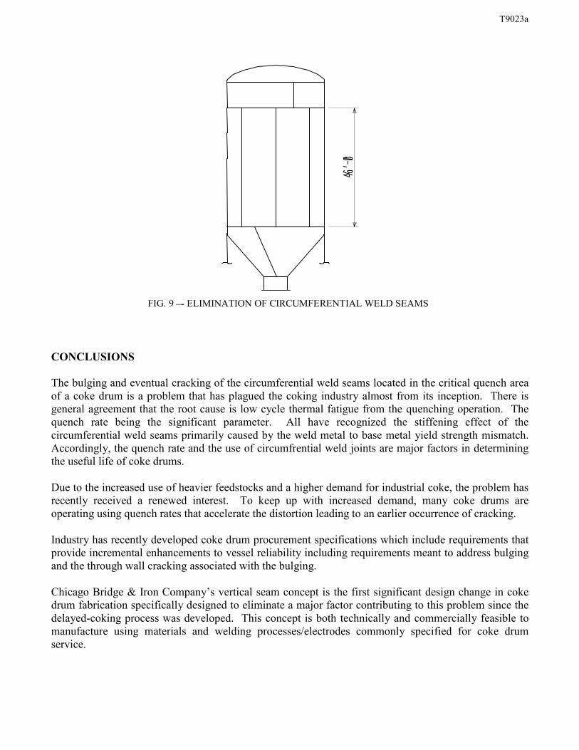
Incorporating technology and know how from other applications, shell plates have been successfullyfabricated with the long side orientated vertically. This allows fabrication of cylindrical shell sections ofup to approximately 46 feet in height without a circumferential weld seam. Plate size is only limited bythe steel mill manufacturing capability. Currently the largest plates available are in the range of 46 feetin length depending on specified thickness and alloy. The resulting cylindrical shell section can then belocated in the area of the vessel that will experience the most severe thermal cycles (Fig. 9). Dependingon plate size limitations, up to five (5) circumferential weld seams can be eliminated.
In late 1997 Chicago Bridge & Iron Company performed an extensive research (7) and analysis project toinvestigate the feasibility of design, fabrication and erection of a “vertical seam” coke drum. Theresulting conclusion was that such a vessel could be economically produced as reported by Antalffy, et.al. (1999). This method will provide a uniform thickness throughout the cylindrical portion of thevessel. The vertical seam concept can easily be applied to new construction (shop built up or fielderected ). It can also be applied to retrofit applications where the lower cone and top head sections ofthe vessels are reused.
T9023a
FIG. 9 –- ELIMINATION OF CIRCUMFERENTIAL WELD SEAMS
CONCLUSIONS
The bulging and eventual cracking of the circumferential weld seams located in the critical quench areaof a coke drum is a problem that has plagued the coking industry almost from its inception. There isgeneral agreement that the root cause is low cycle thermal fatigue from the quenching operation. Thequench rate being the significant parameter. All have recognized the stiffening effect of thecircumferential weld seams primarily caused by the weld metal to base metal yield strength mismatch.Accordingly, the quench rate and the use of circumfrential weld joints are major factors in determiningthe useful life of coke drums.
Due to the increased use of heavier feedstocks and a higher demand for industrial coke, the problem hasrecently received a renewed interest. To keep up with increased demand, many coke drums areoperating using quench rates that accelerate the distortion leading to an earlier occurrence of cracking.
Industry has recently developed coke drum procurement specifications which include requirements thatprovide incremental enhancements to vessel reliability including requirements meant to address bulgingand the through wall cracking associated with the bulging.
Chicago Bridge & Iron Company’s vertical seam concept is the first significant design change in cokedrum fabrication specifically designed to eliminate a major factor contributing to this problem since thedelayed-coking process was developed. This concept is both technically and commercially feasible tomanufacture using materials and welding processes/electrodes commonly specified for coke drumservice.

T9023a
A vessel fabricated or retrofitted utilizing the vertical seam technology will provide the owner with avessel that has a longer more reliable life than those designed and manufactured using conventionaldesigns that place circumfrential weld seams in the critical area of the vessel.
REFERENCES
(1) Weil N.A. and Rapasky F.S., “Experience With Vessels of Delayed - Coking Units”, API 23rd
Midyear Meeting, 1958
(2) Boswell R.S., Ferraro T., “Remaining Life Evaluation of Coke Drums”, Plant Engineering, Designand Responsibility Symposium, Energy Engineering Conference, 1997
(3) Antalffy L.P., Malek D.W., Pfeifer J.A., Stewart C.W., Grimsley B., Shockley R., “Innovations inDelayed Coking Coke Drum Design”, ASME, 1999
(4) Livingston B., Saunders K.L., “Coke Drums Failure Prediction Evaluation Using ProbabilisticTechniques”, ASME, 1998
(5) Penso J.A., Lattarulo Y.M., Seijas A.J., and Torres J., Howden D. and Tsai C.L., “UnderstandingFailure Mechanisms to Improve Reliability of Coke Drums”, ASME, 1999
(6) Swain E.J., “U.S. Petroleum Coke Production Expected to Increase”, Oil & gas Journal, Nov. 10,1997
(7) U.S. and Foreign patents pending.
(8) ASME Section II parts A & C, plus Plate and Electrode Manufacturers brochures and CB&I data.