Coherent DWDM Technologies - BME-HITjakab/edu/litr/Core/WDM/Infinera_Coherent_Tech.pdf · Coherent...
16
Coherent DWDM Technologies Network bandwidth is growing at staggering rates estimated to approximate 40% growth year over year driven by cloud, mobile, and video. Techniques to increase optical bandwidth cost efficiently through Dense Wave Division Multiplexing (DWDM) have begun to get more complex and therefore more technically challenging to implement. This paper reviews the progress and techniques used to increase optical channel capacity from 2.5G to 100G and beyond with a particular focus on coherent transmission technologies, and stresses the importance of practical and robust implementations that deliver cost- effective and highly reliable optical transport. WHITE PAPER
Transcript of Coherent DWDM Technologies - BME-HITjakab/edu/litr/Core/WDM/Infinera_Coherent_Tech.pdf · Coherent...
Coherent DWDM TechnologiesNetwork bandwidth is growing at staggering rates estimated to approximate 40% growth year over year driven by cloud, mobile, and video. Techniques to increase optical bandwidth cost efficiently through Dense Wave Division Multiplexing (DWDM) have begun to get more complex and therefore more technically challenging to implement. This paper reviews the progress and techniques used to increase optical channel capacity from 2.5G to 100G and beyond with a particular focus on coherent transmission technologies, and stresses the importance of practical and robust implementations that deliver cost-effective and highly reliable optical transport.
WHITE PAPER

Page 2
DWDM “Speed Limits”—10Gb/s and 100Gb/s Channels
When DWDM was first introduced in the mid-90s, the typical wavelength data rate was 2.5 Gb/s. Additional fiber capacity was initially provided by increasing the channel count on the fiber as wavelength muxing and demuxing components became more capable. The move to 10 Gb/s wavelengths was enabled by higher performance optical modulators, and also by a better understanding of chromatic dispersion management and the availability of dispersion compensating fibers.1 However, the same simple modulation format was used at both 2.5 Gb/s and 10 Gb/s. This modulation technique is Intensity Modulation with Direct Detection (IM-DD); also known as On/Off Keying (OOK) and Non-Return to Zero (NRZ). IM-DD has served the industry well, but it is no longer particularly efficient in spectrum utilization, and is very susceptible to fiber impairments, such as chromatic dispersion (CD) and polarization mode dispersion (PMD), as the data rate increases beyond 10 Gb/s.
Initial attempts to break the “10G barrier” resulted in 40Gb/s transponders that used slightly more complex modulation, such as Optical Duobinary (ODB) and Differential Phase Shift Keying (DPSK). These implementations were commercially unsuccessful, mainly because their optical reach was inadequate for long haul deployment. In particular Polarization Mode Dispersion (PMD) becomes a significant problem at data rates above 10Gb/s, and these early implementations required expensive and power-hungry external PMD compensation systems. To make things more challenging for 40Gb/s, the cost of 10Gb/s IM-DD systems has continued to fall significantly and thus made the economic case for switching to 40G somewhat difficult to justify.2
As shown in Figure 1, the technological breakthrough that allowed the “10G Speed Limit” to be broken was the introduction of coherent optical technologies, initially for 40Gb/s and soon after for 100Gb/s long haul transmission. Note that in this figure the dates shown are based on commercial availability, and not on “hero experiments”.
1995 2000 2005 2010 2015
2.5G
40G
100G
500G
1T
10G
Enabled by:• High speed modulators• Dispersion management
Enabled by:• Large scale PIC and
coherent technologies
Enabled by:• Coherent technologies
CoherentSuper Channels
Figure 1: The technology enablers for DWDM capacity
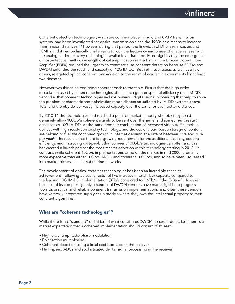
Coherent detection technologies, which are commonplace in radio and CATV transmission systems, had been investigated for optical transmission since the 1980s as a means to increase transmission distances.3,4 However during that period, the linewidth of DFB lasers was around 50MHz and it was technically challenging to lock the frequency and phase of a receive laser with the analog carrier recovery technologies available at that time. More significantly the emergence of cost-effective, multi-wavelength optical amplification in the form of the Erbium Doped Fiber Amplifier (EDFA) reduced the urgency to commercialize coherent detection because EDFAs and DWDM extended the reach and capacity of 10G IM-DD. Both of these issues, as well as a few others, relegated optical coherent transmission to the realm of academic experiments for at least two decades.
However two things helped bring coherent back to the table. First is that the high order modulation used by coherent technologies offers much greater spectral efficiency than IM-DD. Second is that coherent technologies include powerful digital signal processing that help to solve the problem of chromatic and polarization mode dispersion suffered by IM-DD systems above 10G, and thereby deliver vastly increased capacity over the same, or even better distances.
By 2010-11 the technologies had reached a point of market maturity whereby they could genuinely allow 100Gb/s coherent signals to be sent over the same (and sometimes greater) distances as 10G IM-DD. At the same time the combination of increased video traffic, mobile devices with high resolution display technology, and the use of cloud-based storage of content are helping to fuel the continued growth in internet demand at a rate of between 35% and 50% per year5. The result is that there is a growing requirement for the additional capacity, spectral efficiency, and improving cost-per-bit that coherent 100Gb/s technologies can offer; and this has created a launch pad for the mass-market adoption of this technology starting in 2012. IIn contrast, while coherent 40Gb/s implementations came on the market in mid 2000 it remains more expensive than either 10Gb/s IM-DD and coherent 100Gb/s, and so have been “squeezed” into market niches, such as submarine networks.
The development of optical coherent technologies has been an incredible technical achievement—allowing at least a factor of five increase in total fiber capacity compared to the leading 10G IM-DD implementation (8Tb/s compared to 1.6Tb/s in the C-Band). However because of its complexity, only a handful of DWDM vendors have made significant progress towards practical and reliable coherent transmission implementations, and often these vendors have vertically integrated supply chain models where they own the intellectual property to their coherent algorithms.
What are “coherent technologies”?
While there is no “standard” definition of what constitutes DWDM coherent detection, there is a market expectation that a coherent implementation should consist of at least:
• High order amplitude/phase modulation• Polarization multiplexing• Coherent detection using a local oscillator laser in the receiver• High-speed ADCs and sophisticated digital signal processing in the receiver
Page 3

One of the reasons that there are so few practical implementations of coherent technologies on the market today is that these elements require an unusual mixture of optical, digital and radio modem experience, coupled with a very demanding optical transmitter and receiver circuit design. Infinera can claim a world class coherent engineering team and has made a significant investment in coherent technology development—this is clearly illustrated by the performance of our highly integrated implementation.
High order amplitude/phase modulation
Many of the optical “hero experiments” of the early 2000s were aimed at increasing the data rate per DWDM channel beyond what was possible using 10G IM-DD. The “10G barrier” was caused because of the sensitivity of IM-DD to fiber impairments as the data rate was increased, and so alternative modulation techniques were investigated.
Phase shift keying modulation, such as Differential Phase Shift Keying (DPSK) and Differential Quadrature Phase Shift Keying (DQPSK) were favored because, in the case of DPSK, there is a significant advantage in the required optical signal to noise ratio (OSNR) as compared to IM-DD.
In addition, by encoding more amplitude/phase changes in the carrier, it is possible to increase the number of bits carried in each symbol, and the sensitivity to fiber impairments relates to the symbol rate (not directly to the bit rate).
Figure 2 shows the basic principle of amplitude/phase modulation, in which there is a simple transmitter circuit that uses a Mach Zehnder Modulator (MZM) to encode one data stream onto the optical carrier. This is known, depending on the exact details of the implementation, as Phase Shift Keying (PSK); or Binary Phase Shift Keying (BPSK); or if the data is differentially encoded so that the bits are represented by phase changes, and not the absolute phase states, Differential Phase Shift Keying (DPSK). Light from the laser enters the MZM at Point A, and is divided into two so that it passes over the upper and lower arms of the waveguide. At Point B, a signal can be applied to the waveguide that changes the refractive index, and thus the effective velocity of the light at that point. So when the two parts of the light are recombined at Point C there is a series
Page 4
B
A C
Mach-Zehnder Modulator
A simple optical circuit produces a simple, phase modulation.
PSK1 bitper symbol
Figure 2: A single Mach Zehnder Modulator, and the resulting phase constellation

of phase changes encoded onto the light that are directly related to the input signal. The right hand side of Figure 2 shows a simple phase constellation of a generic PSK. In a given clock cycle, if a phase symbol exists on the left of the constellation then the receiver would interpret this is a “1”. If the phase symbol exists on the right of the constellation then the receiver interprets this bit as a “0”. In contrast, a differential system would look for phase state changes.
A more complex optical transmitter is shown in Figure 3. Here we see a series of nested MZM components, known as a Super Mach-Zehnder, and each red block represents a data input point for a portion of the overall modulation signal. The upper MZM forms the so-called in-phase (I) signal and the lower MZM (passing through a π/2, or 90-deg phase shift) forms the quadrature (Q) signal for QPSK/QAM.
By using more complex drive signals this same super Mach-Zehnder structure can be used to generate all of the amplitude/phase modulation techniques shown on the right of Figure 3. This move towards higher order modulation allows more bits to be carried by each symbol. QPSK carries 2 bits in each symbol. However, by doubling the number of phase states we do not double the number of bits per symbol. While this might not seem self-evident at first, consider a binary representation, as shown in the table below. Each phase state represents one permutation of bits in the symbol.
Page 5
Figure 3: High order modulation using a super Mach Zehnder structure
QPSK
8QAM
16QAMI and Q modulation inputs for QPSK/QAM
I
Q
A more complex optical circuit can produce higher
order modulation, shown here…
All of these modulations are on a single polarization state
2 bitsper symbol
3 bitsper symbol
4 bitsper symbol
Binary digits Possible PermutationsEquivalent number of amplitude/phase states
1 0, 1 2 (BPSK)
2 00, 01, 10, 11 4 (QPSK)
3 000, 001, 010, 011, 100, 101, 110, 111 8 (8QAM)
4 0000, 0001, 0010, 0011, 0100, 0101, 0110, 0111, 1000, 1001, 1010, 1011, 1100, 1101, 1110, 1111
16 (16QAM)
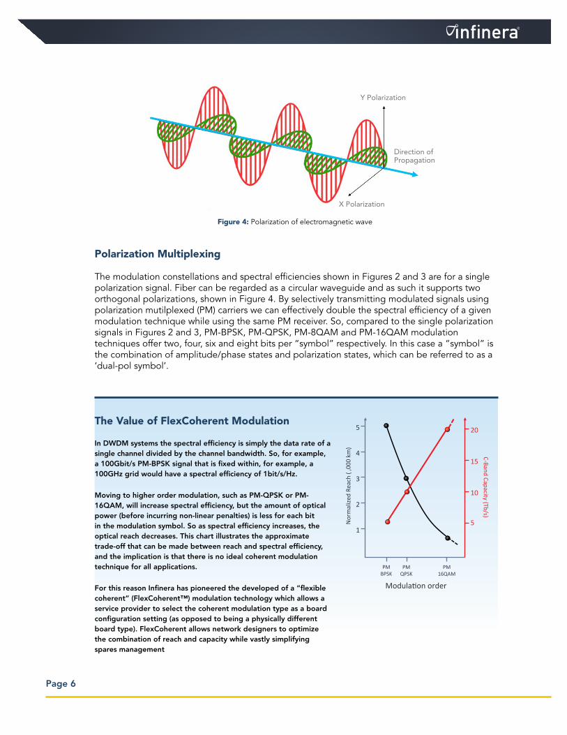
Polarization Multiplexing
The modulation constellations and spectral efficiencies shown in Figures 2 and 3 are for a single polarization signal. Fiber can be regarded as a circular waveguide and as such it supports two orthogonal polarizations, shown in Figure 4. By selectively transmitting modulated signals using polarization mutilplexed (PM) carriers we can effectively double the spectral efficiency of a given modulation technique while using the same PM receiver. So, compared to the single polarization signals in Figures 2 and 3, PM-BPSK, PM-QPSK, PM-8QAM and PM-16QAM modulation techniques offer two, four, six and eight bits per “symbol” respectively. In this case a “symbol” is the combination of amplitude/phase states and polarization states, which can be referred to as a ‘dual-pol symbol’.
Page 6
The Value of FlexCoherent Modulation
In DWDM systems the spectral efficiency is simply the data rate of a single channel divided by the channel bandwidth. So, for example, a 100Gbit/s PM-BPSK signal that is fixed within, for example, a 100GHz grid would have a spectral efficiency of 1bit/s/Hz.
Moving to higher order modulation, such as PM-QPSK or PM-16QAM, will increase spectral efficiency, but the amount of optical power (before incurring non-linear penalties) is less for each bit in the modulation symbol. So as spectral efficiency increases, the optical reach decreases. This chart illustrates the approximate trade-off that can be made between reach and spectral efficiency, and the implication is that there is no ideal coherent modulation technique for all applications.
For this reason Infinera has pioneered the developed of a “flexible coherent” (FlexCoherent™) modulation technology which allows a service provider to select the coherent modulation type as a board configuration setting (as opposed to being a physically different board type). FlexCoherent allows network designers to optimize the combination of reach and capacity while vastly simplifying spares management
Modulation order
Nor
mal
ized
Reac
h ( ,
000
km)
PMBPSK
PMQPSK
PM16QAM
1
2
3
4
5
C-Band Capacity (Tb/s)
5
10
15
20
Y Polarization
X Polarization
Direction of Propagation
Figure 4: Polarization of electromagnetic wave

Figure 5 shows a schematic of a transmitter that would be required to generate, for example, a 100Gb/s single carrier PM-QPSK modulation constellation. Notice that the light from a single laser signal is split and sent into four separate Mach Zehnder modulators (MZMs).
The upper and lower portions of this super Mach Zehnder structure each generate a QPSK signal. The signals are then sent into a Polarization Beam Combiner so that the signal from the upper half of the circuit becomes X-polarized, while the signal from the lower half of the circuit becomes Y-polarized.
Note that the overall bit rate of the PM-QPSK transmitter is four times the symbol rate of each MZM. This division of processing is especially useful in allowing a high data rate digital signal to be divided into multiple parts, so that lower speed electro-optics can be used. The signal input points are shown by the red and green boxes in Figure 5.
The resulting 100G PM-QPSK signal is shown on the right hand side of Figure 5. Note that the red and green colors of the peaks are merely to illustrate the two different polarization states. The signals are, in fact, on exactly the same wavelength. This type of modulation means that a 100Gb/s signal would occupy roughly 38GHz of optical spectrum—thus fitting well inside the traditional 50GHz grid defined in ITU G.694.1.
Figure 6 shows an alternative implementation of 100Gb/s transmission, which is currently used by the most popular commercial implementation. This is a dual carrier implementation, in which two, 50Gb/s single carrier data streams are transmitted in the equivalent of a 50GHz DWDM channel. This has effectively the same spectral efficiency as the single carrier implementation shown in Figure 5, and it has at least as good optical reach. But the primary advantage of a dual carrier implementation is that the opto-electronics only need to operate at 12.5GBaud, plus overhead, compared to the 25GBaud plus overhead needed in a single carrier implementation. Note that
Page 7
Figure 5: Schematic of 100Gb/s, single carrier, PM-QPSK transmitter, and the resulting phase constellations on each polarization state
100G PM-QPSK38GHz
Becomes X-Pol
Becomes Y-Pol
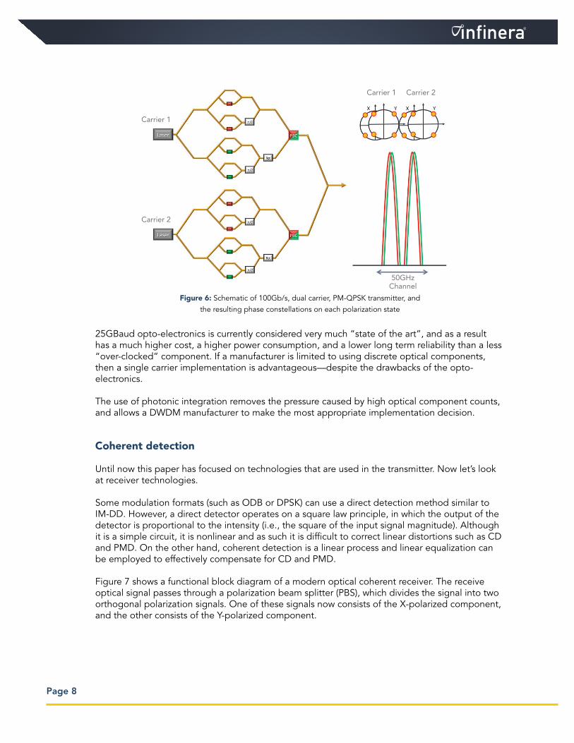
25GBaud opto-electronics is currently considered very much “state of the art”, and as a result has a much higher cost, a higher power consumption, and a lower long term reliability than a less “over-clocked” component. If a manufacturer is limited to using discrete optical components, then a single carrier implementation is advantageous—despite the drawbacks of the opto-electronics.
The use of photonic integration removes the pressure caused by high optical component counts, and allows a DWDM manufacturer to make the most appropriate implementation decision.
Coherent detection
Until now this paper has focused on technologies that are used in the transmitter. Now let’s look at receiver technologies.
Some modulation formats (such as ODB or DPSK) can use a direct detection method similar to IM-DD. However, a direct detector operates on a square law principle, in which the output of the detector is proportional to the intensity (i.e., the square of the input signal magnitude). Although it is a simple circuit, it is nonlinear and as such it is difficult to correct linear distortions such as CD and PMD. On the other hand, coherent detection is a linear process and linear equalization can be employed to effectively compensate for CD and PMD.
Figure 7 shows a functional block diagram of a modern optical coherent receiver. The receive optical signal passes through a polarization beam splitter (PBS), which divides the signal into two orthogonal polarization signals. One of these signals now consists of the X-polarized component, and the other consists of the Y-polarized component.
Carrier 1 Carrier 2
Carrier 1
Carrier 2
50GHzChannel
Figure 6: Schematic of 100Gb/s, dual carrier, PM-QPSK transmitter, and the resulting phase constellations on each polarization state
Page 8
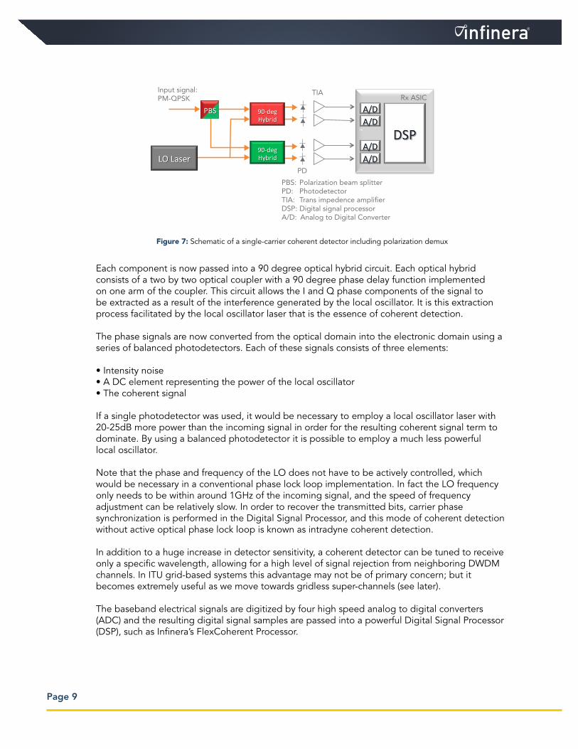
Each component is now passed into a 90 degree optical hybrid circuit. Each optical hybrid consists of a two by two optical coupler with a 90 degree phase delay function implemented on one arm of the coupler. This circuit allows the I and Q phase components of the signal to be extracted as a result of the interference generated by the local oscillator. It is this extraction process facilitated by the local oscillator laser that is the essence of coherent detection.
The phase signals are now converted from the optical domain into the electronic domain using a series of balanced photodetectors. Each of these signals consists of three elements:
• Intensity noise• A DC element representing the power of the local oscillator• The coherent signal
If a single photodetector was used, it would be necessary to employ a local oscillator laser with 20-25dB more power than the incoming signal in order for the resulting coherent signal term to dominate. By using a balanced photodetector it is possible to employ a much less powerful local oscillator.
Note that the phase and frequency of the LO does not have to be actively controlled, which would be necessary in a conventional phase lock loop implementation. In fact the LO frequency only needs to be within around 1GHz of the incoming signal, and the speed of frequency adjustment can be relatively slow. In order to recover the transmitted bits, carrier phase synchronization is performed in the Digital Signal Processor, and this mode of coherent detection without active optical phase lock loop is known as intradyne coherent detection.
In addition to a huge increase in detector sensitivity, a coherent detector can be tuned to receive only a specific wavelength, allowing for a high level of signal rejection from neighboring DWDM channels. In ITU grid-based systems this advantage may not be of primary concern; but it becomes extremely useful as we move towards gridless super-channels (see later).
The baseband electrical signals are digitized by four high speed analog to digital converters (ADC) and the resulting digital signal samples are passed into a powerful Digital Signal Processor (DSP), such as Infinera’s FlexCoherent Processor.
Figure 7: Schematic of a single-carrier coherent detector including polarization demux
""
""""
""""
PBS: Polarization beam splitterPD: PhotodetectorTIA: Trans impedence ampli�erDSP: Digital signal processorA/D: Analog to Digital Converter
Input signal:PM-QPSK
PD
TIARx ASIC
Page 9

Page 10
Infinera FlexCoherent™ Processor
The ability to process the received optical signal in the digital domain will represent one of the biggest differentiators for commercial coherent DWDM implementations. In implementations such as the one shown in Figure 7, the FlexCoherent Digital Signal Processor (DSP) performs three critical functions.
• Chromatic Dispersion compensation. The DSP can compensate for practically any amount of chromatic dispersion that would be found in real fibers. This opens up the possibility of removing dispersion compensating fiber (DCF) from routes that use coherent detection. In fact, coherent systems work better for the links without DCFs. This is because higher chromatic dispersion will help to offset non-linear effects such as SPM and XPM, and thereby increase the effective reach of the signal. Chromatic dispersion changes slowly and the dispersion compensation can be done at low speed within the DSP. Note also that chromatic dispersion compensation is the same for the X-polarized and Y-polarized parts of the signal, and there is no cross-coupling between the two polarizations.
• Polarization Mode Dispersion compensation. After chromatic dispersion compensation, the DSP compensates for dynamic Jones rotation (where the polarization state of the signal has changed on its journey along the fiber) and Polarization Mode Dispersion. Once again, it has been shown that a high quality DSP algorithm is able to compensate for even the highest levels of practical PMD observed in fibers today. In practice, PMD transients are faster than chromatic dispersion variations and as such PMD compensation is done at medium speed, of the order of a few kHz.
• Intradyne Carrier Recovery. As explained above, in modern optical coherent detection the preferred form of signal mixing is known as intradyne detection, in which a free-running local oscillator is used. Carrier recovery between the receive signal and the local oscillator
What are “cycle slips”?
In typical diagrams of QPSK or QAM modulation, the constellations are normally represented as nice, clean values (A). In fact, as the phase modulated signal travels along a typical fiber link, noise from the amplifiers will tend to “smudge” these circles, and jitter induced by non-linear effects will cause the smudges to grow and shrink around the original constellation points (B).
However, the real problem arises because of the instantaneous phase difference between the transmit and receive (local oscillator) lasers. These phase difference cause the constellation to “rotate” (C), and this in turn may cause the receiver to misinterpret the QPSK/QAM symbol. The end result is a series of “cycle slips” that may product data errors that cannot be corrected by the G.709 FEC.
A robust coherent implementation, such as the Infinera FlexCoherent Processor, includes measures to reliably recognize cycle slips when they occur.
A
B
C

Page 11
is performed digitally in the DSP. In an intradyne implementation, the DSP can track local oscillator phase noise for both the transmitter and the local oscillator laser by performing carrier recovery. The offset frequency and the phase noise will be tracked by the digital carrier recovery in the DSP. This carrier recovery process has the highest speed of all the demodulation functions in the DSP.
These three functions, with an indication of their performance requirement, are shown in Figure 8. In this Figure RX represents the received X-polarization signal, and RY represents the received Y-polarization signal.
What comes after 100G? Coherent Super-Channels
In the discussion of Figure 1 it was highlighted that, over the past thirty years, there has been a general expectation that individual wavelength data rates will continue to increase as network demand continues to rise, and as transmission technologies evolve. It was suggested that for a long period (from the early 2000s even until the time of writing) 10G IM-DD represented a barrier thanks to its simplicity and low cost per bit. Likewise it was suggested that a 100G barrier may also exist today.
The emergence of the commercial coherent technologies described above in the 2010 period allowed a dramatic improvement towards 100G transmission per wavelength, with far greater spectral efficiency, and equivalent (or sometimes better) optical reach compared to 10G IM-DD systems.
However, it is now likely that further improvement in optical processing will be at a more evolutionary rate for the foreseeable future. In fact the next big breakthrough will most likely be the adoption of more powerful non-linear compensation techniques in the coherent detector, and these will require a significant increase in DSP processing power. Moore’s Law will eventually deliver this DSP capability, but it is desirable to continuously develop simplified and effective algorithms that could make nonlinear compensation implementable.
Figure 8: Infinera FlexCoherent Processor functional blocks

Page 12
So the answer to the question “what comes after 100G?” is not likely to be a single-carrier 200G, or 500G, or even a 1 terabit “single carrier” transponder. Rather, the increased spectral efficiency and receiver specificity offered by high order modulation and coherent detection opens the door to the implementation of coherent super-channels.
A super-channel is an evolution in DWDM in which multiple, coherent carriers are implemented in a single line card, brought into service in a single operational cycle, and are seen as a seamless, aggregate unit of capacity by the DWDM line system. The principle is shown in Figure 9, where a single-laser, 1Tb/s PM-QPSK transmitter is compared to a ten-laser, 1Tb/s PM-QPSK super-channel. By ignoring the ITU-T G.694.1 50GHz grid, the ten-laser super-channel will have the same spectral width as the single-laser transmitter. The channels are now “squeezed together”, and we rely on the wavelength specificity that can be achieved in a coherent detector to ensure there is no cross-channel interference at the super-channel receiver.
The 320 GBaud electronics and associated 11 nm silicon required by the single-laser implementation on the left will likely not exist for another ten years, according to electronics industry roadmaps. However, since the ten-laser super-channel effectively divides the load by a factor of ten, this level of electronics is available today and can be productized within approximately 2 years.
Figure 6 shows a dual carrier, 100G PM-QPSK implementation, which is in fact a dual carrier super-channel. Even with just two carriers the optical component count is high. For ten carriers it would be impractical to build a super-channel line card using discrete components. Large scale photonic integration will be mandatory for any practical implementation.
The central focus of this whitepaper is coherent technology, but Infinera has a specific whitepaper available that discusses coherent super-channels. Please check out the Resources section of the Infinera website for the whitepaper “Super-Channels: DWDM Transmission Beyond 100Gb/s”.
Components 1 laser 10 lasers
4 modulators 40 modulators
320 Gbaud electronics 32 Gbaud electronics
Limiting component ~11nm Silicon Terabit PIC
Time to market ~10 years ~2 years
Figure 9: The electronic component impact of single carrier transmission versus multi-carrier super-channels
1 Tb/s PM-QPSK
375 GHz 375 GHz
Page 13
Deployment Experience
From the very beginning of Infinera’s coherent development program the company made two critical decisions. First is that 100Gb/s operational units are already insufficient for the world’s larger service providers; and with a 40% annual increase in internet demand the set of customers for whom 100G is not enough is growing larger all the time. Infinera’s solution to this problem is a 500G super-channel line card which is being deployed today, with next evolution to 1Tb/s in a single line card.
The second key decision was to make the technology leap from large scale PICs with IM-DD modulation to a world-leading, PIC-based coherent implementation.6 More importantly the type of PIC that is essential to deliver cost-effective integration benefits is a large scale, monolithic design—which implies fabrication of all optical functions in a single material (ie. Indium Phosphide). Building high speed InP Mach-Zehnder modulators requires total mastery of the chip design, component optimization and manufacturing quality, and it is these three area of excellence that Infinera has brought together in the 500G PIC chipset.
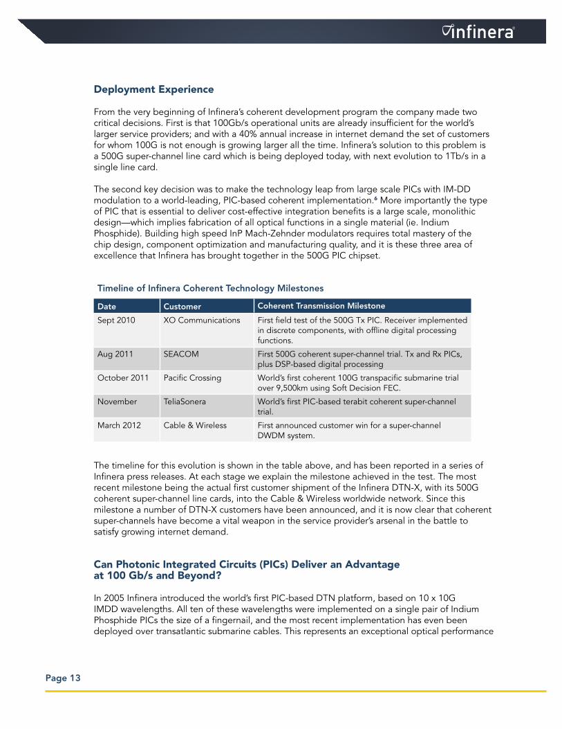
The timeline for this evolution is shown in the table above, and has been reported in a series of Infinera press releases. At each stage we explain the milestone achieved in the test. The most recent milestone being the actual first customer shipment of the Infinera DTN-X, with its 500G coherent super-channel line cards, into the Cable & Wireless worldwide network. Since this milestone a number of DTN-X customers have been announced, and it is now clear that coherent super-channels have become a vital weapon in the service provider’s arsenal in the battle to satisfy growing internet demand.
Can Photonic Integrated Circuits (PICs) Deliver an Advantage at 100 Gb/s and Beyond?
In 2005 Infinera introduced the world’s first PIC-based DTN platform, based on 10 x 10G IMDD wavelengths. All ten of these wavelengths were implemented on a single pair of Indium Phosphide PICs the size of a fingernail, and the most recent implementation has even been deployed over transatlantic submarine cables. This represents an exceptional optical performance
Timeline of Infinera Coherent Technology Milestones
Date Customer Coherent Transmission Milestone
Sept 2010 XO Communications First field test of the 500G Tx PIC. Receiver implemented in discrete components, with offline digital processing functions.
Aug 2011 SEACOM First 500G coherent super-channel trial. Tx and Rx PICs, plus DSP-based digital processing
October 2011 Pacific Crossing World’s first coherent 100G transpacific submarine trial over 9,500km using Soft Decision FEC.
November TeliaSonera World’s first PIC-based terabit coherent super-channel trial.
March 2012 Cable & Wireless First announced customer win for a super-channel DWDM system.

Page 14
for an IMDD modulation technique, and helps to prove that a move to photonic integration does not require a compromise in optical performance—at least for IMDD. Coherent transmission at 100G not only requires many more optical components than IMDD, but the optical performance of these components is so much more demanding.
There is a significant increase in optical component complexity as transmission rates move from 10G NRZ, through 40G and 100G coherent, and then on to 500G super-channels. But given the increasing importance of electronic impairment compensation used in coherent receivers, is photonic integration essential in order to implement a 100 Gb/s transponder? Clearly the existence of 100 Gb/s transponders based on discrete optical components shows that it’s possible to avoid the investment in developing 100G coherent PICs. However, a cost breakdown for a typical discrete 100 Gb/s, single carrier PM-QPSK transponder is shown in Figure 10. The “complex electronics” is actually implemented in a highly integrated electronic ASIC, leaving the majority of the cost in the form of the optical components.
By collapsing all the optical components shown in Figures 5, 7 and 10, as well as the optical components for four other 100G channels, onto a single pair of PICs (one for transmit, one for receive), Infinera has been able to massively reduce optical circuit implementation complexity, reduce footprint and power consumption, and increase reliability. But can this kind of highly integrated implementation deliver true coherent optical performance?
To prove the capabilities of our coherent implementation, Infinera recently embarked upon a radical stress test that involved levels of chromatic dispersion and PMD that are unlikely to be encountered in real optical fibers.7 Two conditions were analyzed:
The first, focused on static PMD, involved increasing the PMD to a given value (using a PMD simulator), after which the Bit-Error Ratio (BER) performance for each PMD value was measured.
The PIC-based implementation was able to tolerate peak PMD levels of 500 ps.100G Transponder Cost Breakdown
Op'cal Components
74%
Coherent ASIC
11%
Other Components
15%
Figure 10: Es<mated cost breakdown for 100G, SC-‐PM-‐QPSK transponder
Figure 10: Estimated cost breakdown for 100G, SC-PM-QPSK transponder
Page 15
The second condition looked at the way that high frequency PMD transients can affect performance. Transient PMD was generated using fixed Differential Group Delay (DGD) elements separated by polarization rotators, with the rotators inducing polarization slew rates of over 10,000 radians per second. This test shows robustness to time varying polarization and PMD. We believe that the PMD tolerance results presented here constitute the highest PMD tolerance to date recorded for 100 Gb/s systems.
One might argue that these PMD compensation results actually illustrate the power and quality of the DSP algorithm. But the DSP could not perform to this level if there were significant penalties caused by a PIC-based implementation. In fact, since the PMD tolerance results for a PIC-based implementation are actually better than those currently published for discrete optical implementations, the optical performance of coherent PICs must be extremely good.
Conclusion
Within the DWDM industry the combination of four key technologies now represents the state of the art in efficient DWDM transmission. These are advanced modulation (QPSK/QAM), polarization multiplexing, coherent detection, and high-speed ADC/DAC with advanced digital signal processing. Together these “coherent technologies” have allowed the DWDM industry to transform from 10G per DWDM channel to 100G per DWDM channel. The result is an order of magnitude increase in spectral efficiency, while retaining the same, or in many cases superior optical reach. Coherent technologies also make the line system simpler by removing the need for Dispersion Compensation Modules. To further improve the line rate and spectral efficiency, multi-carrier super-channel technologies are now being deployed, and these inherently require a greater number of optical components on a single line card. Photonic Integrated Circuits (PICs) with industry leading coherent transmission performance provide a significant implementation advantage at 100 Gb/s, and are essential for multi-carrier coherent super-channels.
References
1 AH Gnauck, RW Tkach, AR Chraplyvy, T. Li; “High-Capacity Optical Transmission Systems”. Journal of Lightwave Technology, Vol 26, No. 9, May 1, 2008
2 Ovum Optical Networks Forecast Report: 2011-16
3 John R. Barry and Edward A. Lee, “Performance of Coherent Optical Receivers,” Proceeding of The IEEE, Vol. 78, No. 8, August 1990, pp.1369-94.
4 M.Taylor, et al., “Coherent detection method using DSP for demodulation of signal and subsequent equalization of propagation impairments,” IEEE Photon. Technol. Lett., Vol. 16, No. 2, Feb. 2004.
5 J. McNicol, et al., “Single-carrier versus sub-carrier bandwidth considerations for coherent optical systems,” SPIE, San Francisco, Jan. 2011.
6 R. Nagarajan, et al., “10 Channel, 100 Gbit/s per channel, dual polarization, coherent QPSK, monolithic InP receiver photonic integrated circuit,” OFC/NFOEC 2011, OML7.
7 Rahn, J.; Sun, H.; Wu, K.T.; Basch, B.E. IEEE Journal of Lightwave Technology, 2012, Issue 99: Real-Time PMD Tolerance Measurements of a PIC Based 500Gb/s Coherent Optical Modem.

Infinera Corporation140 Caspian CourtSunnyvale, CA 94089 USATelephone: +1 408 572 5200Fax: +1 408 572 5454www.infinera.com
Have a question about Infinera’s products or services?Please contact us via the email addresses below.
Americas: [email protected] & Pacific Rim: [email protected], Middle East, and Africa: [email protected] E-Mail: [email protected]
www.infinera.com
Specifications subject to change without notice.
Document Number: WP-CT-10-2012© Copyright 2012 Infinera Corporation. All rights reserved.Infinera, Infinera DTN™, IQ™, Bandwidth Virtualization™, Digital Virtual Concatenation™ andInfinera Digital Optical Network™ are trademarks of Infinera Corporation