Código Internacional de Plomería. 2009
173
NOTICE OF INCORPORATION United States Legal Document ≠ All citizens and residents are hereby advised that this is a legally binding document duly incorporated by reference and that failure to comply with such requirements as hereby detailed within may subject you to criminal or civil penalties under the law. Ignorance of the law shall not excuse noncompliance and it is the responsibility of the citizens to inform themselves as to the laws that are enacted in the United States of America and in the states and cities contained therein. ± « ICC IPC (2009), the International Plumbing Code, as mandated and incorporated by the States and Municipalities, including Alabama, Colorado, Delaware, Florida, Michigan, New Hampshire, North Carolina, Ohio, Oklahoma, Pennsylvania, Rhode Island, Utah, Vermont, Virginia, West Virginia, et. alia.
-
date post
14-Sep-2014 -
Category
Design
-
view
2.023 -
download
12
description
Transcript of Código Internacional de Plomería. 2009

NOTICE OF INCORPORATIONUnited States Legal Document
≠ All citizens and residents are hereby advised that this is a legally binding document duly incorporated by reference and that failure to comply with such requirements as hereby detailed within may subject you to criminal or civil penalties under the law. Ignorance of the law shall not excuse noncompliance and it is the responsibility of the citizens to inform themselves as to the laws that are enacted in the United States of America and in the states and cities contained therein. ±
«
ICC IPC (2009), the International Plumbing Code, as mandated and incorporated by the States and Municipalities, including Alabama, Colorado, Delaware, Florida, Michigan, New Hampshire, North Carolina, Ohio, Oklahoma, Pennsylvania, Rhode Island, Utah, Vermont, Virginia, West Virginia, et. alia.


A MEMBER OF THE INTERNATIONAL CODE FAMILY®
INTERNATIONAL PLUMBING CODE®
Now IncludesInternational
Private SewageDisposal Code®
2oo!3
Receive FREE updates) excerpts of code references) technicalarticles) and more when you register your code book. Go to
www.iccsafe.org/CodesPlus today!

2009 International Plumbing Code®
First Printing: January 2009
ISBN: 978-1-58001-733-6 (soft-cover edition)ISBN: 978-1-58001-732-9 (loose-leaf edition)
COPYRIGHT © 2009by
INTERNATIONAL CODE COUNCIL, INC.
ALL RIGHTS RESERVED. This 2009 International Plumbing Code® is a copyrighted work owned by the International CodeCouncil, Inc. Without advance written permission from the copyright owner, no part of this book may be reproduced, distributed ortransmitted in any form or by any means, including, without limitation, electronic, optical or mechanical means (by way ofexample,and not limitation, photocopying, or recording by or in an information storage retrieval system). For information on permission tocopy material exceeding fair use, please contact: Publications, 4051 West Flossmoor Road, Country Club Hills, IL 60478-5795.Phone 1-888-ICC-SAFE (422-7233).
Trademarks: "International Code Council," the "International Code Council" logo and the "International Plumbing Code" aretrademarks of the International Code Council, Inc.
PRINTED IN THE U.S.A.

PREFACE
IntroductionInternationally, code officials recognize the need for a modern, up-to-date plumbing code addressing the design and installation ofplumbing systems through requirements emphasizing performance. The International Plumbing Code®, in this 2009 edition, isdesigned to meet these needs through model code regulations that safeguard the public health and safety in all communities, largeand small.
This comprehensive plumbing code establishes minimum regulations for plumbing systems using prescriptive and performance-related provisions. It is founded on broad-based principles that make possible the use of new materials and new plumbingdesigns. This 2009 edition is fully compatible with all the International Codes@(I-Codes@) published by the International CodeCouncil (ICC) @, including the International Building Code@, International Energy Conservation Code@, International ExistingBuilding Code@, International Fire Code@, International Fuel Gas Code@, International Mechanical Code@, ICC PerformanceCode@, International Private Sewage Disposal Code@, International Property Maintenance Code@, International ResidentialCode@, International Wildland-Urban Interface Code™and International Zoning Code@.
The International Plumbing Code provisions provide many benefits, among which is the model code development process thatoffers an international forum for plumbing professionals to discuss performance and prescriptive code requirements. This forumprovides an excellent arena to debate proposed revisions. This model code also encourages international consistency in the application of provisions.
DevelopmentThe first edition of the International Plumbing Code (1995) was the culmination of an effort initiated in 1994 by a developmentcommittee appointed by the ICC and consisting of representatives of the three statutory members of the International Code Councilat that time, including: Building Officials and Code Administrators International, Inc. (BOCA), International Conference of Building Officials (lCBO) and Southern Building Code Congress International (SBCCI). The intent was to draft a comprehensive set ofregulations for plumbing systems consistent with and inclusive of the scope of the existing model codes. Technical content of thelatest model codes promulgated by BOCA, ICBO and SBCCI was utilized as the basis for the development. This 2009 edition presents the code as originally issued, with changes as reflected in the subsequent editions through 2006 and with changes approvedthrough the ICC Code Development Process through 2008. A new edition such as this is promulgated every three years.
This code is founded on principles intended to establish provisions consistent with the scope of a plumbing code that adequatelyprotects public health, safety and welfare; provisions that do not unnecessarily increase construction costs; provisions that do notrestrict the use of new materials, products or methods of construction; and provisions that do not give preferential treatment to particular types or classes of materials, products or methods of construction.
AdoptionThe International Plumbing Code is available for adoption and use by jurisdictions internationally. Its use within a governmentaljurisdiction is intended to be accomplished through adoption by reference in accordance with proceedings establishing thejurisdiction's laws. At the time of adoption, jurisdictions should insert the appropriate information in provisions requiring specific localinformation, such as the name of the adoptingjurisdiction. These locations are shown in bracketed words in small capital letters inthe code and in the sample ordinance. The sample adoption ordinance on page ix addresses several key elements of a code adoptionordinance, including the information required for insertion into the code text.
MaintenanceThe International Plumbing Code is kept up to date through the review of proposed changes submitted by code enforcing officials,industry representatives, design professionals and other interested parties. Proposed changes are carefully considered through anopen code development process in which all interested and affected parties may participate.
The contents of this work are subject to change both through the Code Development Cycles and the governmental body thatenacts the code into law. For more information regarding the code development process, contact the Code and Standard Development Department of the International Code Council.
While the development procedure of the International Plumbing Code ensures the highest degree of care, ICC and ICC's members and those participating in the development of this code do not accept any liability resulting from compliance or noncompliancewith the provisions, since ICC and its members do not have the power or authority to police or enforce compliance with the contentsof this code. Only the governmental body that enacts the code into law has such authority.
2009 INTERNATIONAL PLUMBING CODE® iii

Letter Designations in Front of Section NumbersIn each code development cycle, proposed changes to the code are considered at the Code Development Hearings by the ICCPlumbing Code Development Committee, whose action constitutes a recommendation to the voting membership for final action onthe proposed change. Proposed changes to a code section that has a number beginning with a letter in brackets are considered by adifferent code development committee. For example, proposed changes to code sections that have [B] in front of them (e.g. [B]309.2) are considered by the ICC Building Code Development Committee at the code development hearings.
The content of sections in this code that begin with a letter designation are maintained by another code development committee inaccordance with the following:
[B] International Building Code Development Committee;
[E] International Energy Conservation Code Development Committee;
[F] International Fire Code Development Committee; and
[M] International Mechanical Code Development Committee.
Marginal MarkingsSolid vertical lines in the margins within the body of the code indicate a technical change from the requirements of the 2006 edition.Deletion indicators in the form ofan arrow (.) are provided in the margin where an entire section, paragraph, exception or table hasbeen deleted or an item in a list of items or a table has been deleted.
Italicized TermsSelected terms set forth in Chapter 2, Definitions, are italicized where they appear in code text. Such terms are not italicized wherethe definition set forth in Chapter 2 does not impart the intended meaning in the use of the term. The terms selected have definitionswhich the user should read carefully to facilitate better understanding of the code.
iv 2009 INTERNATIONAL PLUMBING CODE®

Effective Use of the International Plumbing Code
The International Plumbing Code (IPC) is a model code that regulates the design and installation of plumbing systems including theplumbing fixtures in all types ofbuildings except for detached one- and two-family dwellings and townhouses that are not more thanthree stories above grade in height. The regulations for plumbing systems in one- and two-family dwellings and townhouses arecovered by Chapters 25 through 33 of the International Residential Code (IRC).The IPC addresses general plumbing regulations,fixture requirements, water heater installations and systems for water distribution, sanitary drainage, special wastes, venting, stormdrainage and medical gases. The IPC does not address fuel gas piping systems as those systems are covered by the InternationalFuel Gas Code (IFGC). The IPC also does not regulate swimming pool piping systems, process piping systems, or utility-ownedpiping and systems. The purpose of the IPC is to the establish the minimum acceptable level of safety to protect life and propertyfrom the potential dangers associated with supplying potable water to plumbing fixtures and outlets and the conveyance of bacteria-laden waste water from fixtures.
The IPC is primarily a specification-oriented (prescriptive) code with some performance-oriented text. For example, Section405.1 is a performance statement but Chapter 6 contains the prescriptive requirements that will cause Section 405.1 to be satisfied.
Where a building contains plumbing fixtures, those fixtures requiring water must be provided with an adequate supply of waterfor proper operation. The number of required plumbing fixtures for a building is specified by this code and is based upon the anticipated maximum number of occupants for the building and the type of building occupancy. This code provides prescriptive criteriafor sizing piping systems connected to those fixtures. Through the use of code-approved materials and the installation requirementsspecified in this code, plumbing systems will perform their intended function over the life of the building. In summary, the IPC setsforth the minimum requirements for providing safe water to a building as well as a safe manner in which liquid-borne wastes are carried away from a building.
Arrangement and Format of the 2009 IPCThe format of the IPC allows each chapter to be devoted to a particular subject with the exception of Chapter 3 which contains general subject matters that are not extensive enough to warrant their own independent chapter. The IPC is divided into thirteen differentparts:
Chapters Subjects
1-2 Administration and Definitions
3 General Regulations
4 Fixtures, Faucets and Fixture Fittings
5 Water Heaters
6 Water Supply and Distribution
7 Sanitary Drainage
8 Special Wastes
9 Venting
10 Traps, Interceptors, and Separators
11 Storm Drainage
12 Special Piping (Medical Gas)
13 Referenced Standards
Appendices A-G Appendices
The following is a chapter-by-chapter synopsis of the scope and intent of the provisions of the International Plumbing Code:
Chapter 1 Administration. This chapter contains provisions for the application, enforcement and administration of subsequentrequirements of the code. In addition to establishing the scope of the code, Chapter 1 identifies which buildings and structures comeunder its purview. Chapter 1 is largely concerned with maintaining"due process of law" in enforcing the requirements contained inthe body of this code. Only through careful observation of the administrative provisions can the building official reasonably expectto demonstrate that"equal protection under the law" has been provided.
2009 INTERNATIONAL PLUMBING CODE® v

Chapter 2 Definitions. Chapter 2 is the repository of the definitions of terms used in the body of the code. Codes are technical documents and every word, term and punctuation mark can impact the meaning of the code text and the intended results. The code oftenuses terms that have a unique meaning in the code and the code meaning can differ substantially from the ordinarily understoodmeaning of the term as used outside of the code.
The terms defined in Chapter 2 are deemed to be of prime importance in establishing the meaning and intent of the code text thatuses the terms. The user of the code should be familiar with and consult this chapter because the definitions are essential to the correct interpretation of the code and because the user may not be aware that a term is defined.
Where understanding of a term's definition is especially key to or necessary for understanding of a particular code provision, theterm is shown in italics wherever it appears in the code. This is true only for those terms that have a meaning that is unique to thecode. In other words, the generally understood meaning of a term or phrase might not be sufficient or consistent with the meaningprescribed by the code; therefore, it is essential that the code-defined meaning be known.
Guidance regarding tense, gender and plurality of defined terms as well as guidance regarding terms not defined in this code isprovided.
Chapter 3 General Regulations. The content of Chapter 3 is often referred to as "miscellaneous," rather than general regulations.This is the only chapter in the code whose requirements do not interrelate. If a requirement cannot be located in another chapter, itshould be located in this chapter. Chapter 3 contains safety requirements for the installation of plumbing and nonplumbing requirements for all types offixtures. This chapter also has requirements for the identification ofpipe, pipe fittings, traps, fixtures, materialsand devices used in plumbing systems.
The safety requirements of this chapter provide protection for the building's structural members, as well as prevent undue stressand strain on pipes. The building's structural stability is protected by the regulations for cutting and notching ofstructural members.Additional protection for the building occupants includes requirements to maintain the plumbing in a safe and sanitary condition, aswell as privacy for those occupants.
Chapter 4 Fixtures, Faucets and Fixture Fittings. This chapter regulates the minimum number of plumbing fixtures that must beprovided for every type of building. This chapter also regulates the quality of fixtures and faucets by requiring those items to complywith nationally recognized standards. Because fixtures must be properly installed so that they are usable by the occupants of thebuilding, this chapter contains the requirements for the installation of fixtures. Because the requirements for the number of plumbing fixtures affects the design of a building, Chapter 29 of the International Building Code (IBC) includes, verbatim, many of therequirements listed in Chapter 4 of this code.
Chapter 5Water Heaters. Chapter 5 regulates the design, approval and installation ofwater heaters and related safety devices. Theintent is to minimize the hazards associated with the installation and operation ofwater heaters. Although this code does not regulatethe size of a water heater, it does regulate all other aspects of the water heater installation such as temperature and pressure reliefvalves, safety drip pans, installation and connections. Where a water heater also supplies water for space heating, this chapter regulates the maximum water temperature supplied to the water distribution system.
Chapter 6 Water Supply and Distribution. This chapter regulates the supply of potable water from both public and individualsources to every fixture and outlet so that it remains potable and uncontaminated. Chapter 6 also regulates the design of the waterdistribution system, which will allow fixtures to function properly and also help prevent backflow conditions. The unique requirements of the water supply for health care facilities are addressed separately. It is critical that the potable water supply system remainfree of actual or potential sanitary hazards by providing protection against backflow.
Chapter 7 Sanitary Drainage. The purpose of Chapter 7 is to regulate the materials, design and installation of sanitary drainagepiping systems as well as the connections made to the system. The intent is to design and install sanitary drainage systems that willfunction reliably, that are neither undersized nor oversized and that are constructed from materials, fittings and connections as prescribed herein. This chapter addresses the proper use of fittings for directing the flow into and within the sanitary drain piping system. Materials and provisions necessary for servicing the drainage system are also included in this chapter.
Chapter 8 Indirect/Special Waste. This chapter regulates drainage installations that require an indirect connection to the sanitarydrainage system. Fixtures and plumbing appliances, such as those associated with food preparation or handling, health care facilities and potable liquids, must be protected from contamination that can result from connection to the drainage system. An indirectconnection prevents sewage from backing up into a fixture or appliance, thus providing protection against potential health hazards.The chapter also regulates special wastes containing hazardous chemicals. Special waste must be treated to prevent any damage tothe sanitary drainage piping and to protect the sewage treatment processes.
Chapter 9 Vents. Chapter 9 covers the requirements for vents and venting. Knowing why venting is required makes it easier tounderstand the intent of this chapter. Venting protects every trap against the loss of its seal. Provisions set forth in this chapter aregeared toward limiting the pressure differentials in the drainage system to a maximum of 1 inch of water column (249 Pa) above orbelow atmospheric pressure (Le., positive or negative pressures).
Chapter 10 Traps, Interceptors and Separators. This chapter contains design requirements and installation limitations for traps.Prohibited types of traps are specifically identified. Where fixtures do not frequently replenish the water in traps, a method is provided to ensure that the water seal of the trap will be maintained. Requirements for the design and location of various types of inter-
vi 2009 INTERNATIONAL PLUMBING CODE®

ceptors and separators are provided. Specific venting requirements are given for separators and interceptors as those requirementsare not addressed in Chapter 9.
Chapter 11 Storm Drainage. Chapter 11 regulates the removal of storm water typically associated with rainfall. The proper installation of a storm drainage system reduces the possibility of structural collapse of a flat roof, prevents the leakage of water throughthe roof, prevents damage to the footings and foundation ofthe building and prevents flooding of the lower levels of the building.
Chapter 12 Special Piping and Storage Systems. This chapter contains the requirements for the design, installation, storage, handling and use of nonflammable medical gas systems, including inhalation anesthetic and vacuum piping systems, bulk oxygen storage systems and oxygen-fuel gas systems used for welding and cutting operations. The intent of these requirements is to minimizethe potential fire and explosion hazards associated with the gases used in these systems.
Chapter 13 Referenced Standards. The code contains numerous references to standards that are used to regulate materials andmethods of construction. Chapter 13 contains a comprehensive list of all standards that are referenced in the code. The standards arepart of the code to the extent of the reference to the standard. Compliance with the referenced standard is necessary for compliancewith this code. By providing specifically adopted standards, the construction and installation requirements necessary for compliance with the code can be readily determined. The basis for code compliance is, therefore, established and available on an equalbasis to the code official, contractor, designer and owner.
Chapter 13 is organized in a manner that makes it easy to locate specific standards. It lists all of the referenced standards, alphabetically, by acronym of the promulgating agency of the standard. Each agency's standards are then listed in either alphabetical ornumeric order based upon the standard identification. The list also contains the title of the standard; the edition (date) of the standardreferenced; any addenda included as part of the ICC adoption; and the section or sections of this code that reference the standard.
Appendix A Plumbing Permit Fee Schedule. Appendix A provides a format for a fee schedule.
Appendix B Rates ofRainfall for Various Cities. Appendix B provides specific rainfall rates for major cities in the United States.
Appendix C Gray Water Recycling Systems. Appendix C offers a method for utilizing gray water that is collected from certainfixtures such as lavatories, bathtubs, showers and clothes washing machines. Because many geographical areas of the world are inshort supply of water resources, water that has already passed through these fixtures is an important resource that can lessen thedemand for potable water. Where gray water is used for underground irrigation, no treatment other than basic filtering is required. Inthis application, gray water reuse offers savings in both potable water use and waste water treatment. Gray water can also be reusedfor flushing water closets and urinals. In this application, the gray water requires disinfection and coloring in order to be safe for usein those fixtures. This appendix provides the user with basic information to choose the necessary components, size and construct agray water system that suits the particular application.
Appendix D Degree Day and Design Temperatures. This appendix provides valuable temperature information for designers andinstallers of plumbing systems in areas where freezing temperatures might exist.
Appendix E Sizing ofWater Piping System. Appendix E provides two recognized methods for sizing the water service and waterdistribution piping for any structure. The method under Section E103 provides friction loss diagrams which require the user to"plot" points and read values from the diagrams in order to perform the required calculations and necessary checks. This method isthe most accurate of the two presented in this appendix. The method under Section E201 is known to be conservative; however, veryfew calculations are necessary in order to determine a pipe size that satisfies the flow requirements of any application.
Appendix F Structural Safety. Appendix F is provided so that the user does not have to refer to another code book for limitationsfor cutting, notching and boring of sawn lumber and cold-formed steel framing.
Appendix G Vacuum Drainage System. Appendix G offers basic information on how a vacuum drainage system relates the code,should a vacuum drainage system be used for a building.
2009 INTERNATIONAL PLUMBING CODE® vii

viii 2009 INTERNATIONAL PLUMBING CODE®

ORDINANCE
The International Codes are designed and promulgated to be adopted by reference by ordinance. Jurisdictions wishing to adopt the2009 International Plumbing Code as an enforceable regulation governing plumbing systems should ensure that certain factualinformation is included in the adopting ordinance at the time adoption is being considered by the appropriate governmental body.The following sample adoption ordinance addresses several key elements of a code adoption ordinance, including the informationrequired for insertion into the code text.
SAMPLE ORDINANCE FOR ADOPTION OFTHE INTERNATIONAL PLUMBING CODE
ORDINANCE NO.------
An ordinance of the [JURISDICTION] adopting the 2009 edition of the International Plumbing Code, regulating and governing thedesign, construction, quality of materials, erection, installation, alteration, repair, location, relocation, replacement, addition to, useor maintenance of plumbing systems in the [JURISDICTION]; providing for the issuance of permits and collection of fees therefor;repealing Ordinance No. of the [JURISDICTION] and all other ordinances and parts of the ordinances in conflict therewith.
The [GOVERNING BODY] of the [JURISDICTION] does ordain as follows:
Section 1.That a certain document, three (3) copies of which are on file in the office of the [TITLE OF JURISDICTION'S KEEPER OFRECORDS] of [NAME OF JURISDICTION], being marked and designated as the International Plumbing Code, 2009 edition, includingAppendix Chapters [FILL IN THE APPENDIX CHAPTERS BEING ADOPTED], as published by the International Code Council, be and ishereby adopted as the Plumbing Code of the [JURISDICTION], in the State of [STATE NAME] regulating and governing the design, construction, quality of materials, erection, installation, alteration, repair, location, relocation, replacement, addition to, use or maintenance ofplumbing systems as herein provided; providing for the issuance ofpermits and collection offees therefor; and each and allof the regulations, provisions, penalties, conditions and terms of said Plumbing Code on file in the office of the [JURISDICTION] arehereby referred to, adopted, and made a part hereof, as if fully set out in this ordinance, with the additions, insertions, deletions andchanges, if any, prescribed in Section 2 of this ordinance.
Section 2. The following sections are hereby revised:
Section 101.1. Insert: [NAME OF JURISDICTION]
Section 106.6.2. Insert: [APPROPRIATE SCHEDULE]
Section 106.6.3. Insert: [PERCENTAGES IN TWO LOCATIONS]
Section 108.4. Insert: [OFFENSE, DOLLAR AMOUNT, NUMBER OF DAYS]
Section 108.5. Insert: [DOLLAR AMOUNT IN TWO LOCATIONS]
Section 305.6.1. Insert: [NUMBER OF INCHES IN TWO LOCATIONS]
Section 904.1. Insert: [NUMBER OF INCHES]
Section 3. That Ordinance No. of [JURISDICTION] entitled [FILL IN HERE THE COMPLETE TITLE OF THE ORDINANCE ORORDINANCES IN EFFECT AT THE PRESENT TIME SO THAT THEY WILL BE REPEALED BY DEFINITE MENTION] and all other ordinancesor parts of ordinances in conflict herewith are hereby repealed.
Section 4. That ifany section, subsection, sentence, clause or phrase of this ordinance is, for any reason, held to be unconstitutional,such decision shall not affect the validity of the remaining portions of this ordinance. The [GOVERNING BODY] hereby declares that itwould have passed this ordinance, and each section, subsection, clause or phrase thereof, irrespective of the fact that anyone or moresections, subsections, sentences, clauses and phrases be declared unconstitutional.
Section 5. That nothing in this ordinance or in the Plumbing Code hereby adopted shall be construed to affect any suit or proceedingimpending in any court, or any rights acquired, or liability incurred, or any cause or causes of action acquired or existing, under anyact or ordinance hereby repealed as cited in Section 3 ofthis ordinance; nor shall anyjust or legal right or remedy ofany character belost, impaired or affected by this ordinance.
Section 6. That the [JURISDICTION'S KEEPER OF RECORDS] is hereby ordered and directed to cause this ordinance to be published.(An additional provision may be required to direct the number of times the ordinance is to be published and to specify that it is to bein a newspaper in general circulation. Posting may also be required.)
Section 7. That this ordinance and the rules, regulations, provisions, requirements, orders and matters established and adoptedhereby shall take effect and be in full force and effect [TIME PERIOD] from and after the date of its final passage and adoption.
2009 INTERNATIONAL PLUMBING CODE® ix

x 2009 INTERNATIONAL PLUMBING CODE®

TABLE OF CONTENTS
CHAPTER I SCOPE AND ADMINISTRATION ... I
PART I-SCOPE AND APPLICATION I
Section
101 General 1
102 Applicability 1
PART 2-ADMINISTRATION ANDENFORCEMENT 2
103 Department of Plumbing Inspection 2
104 Duties and Powers of the Code Official 2
105 Approval. 2
106 Permits 3
107 Inspections and Testing 5
108 Violations 6
109 Means of Appeal 7
110 Temporary Equipment, Systems and Uses 8
CHAPTER 2 DEFINITIONS 9
Section
201 General 9
202 General Definitions 9
CHAPTER 3 GENERAL REGULATIONS 17
Section
301 General. . . . . . . . . . . . . . . . . . . . . . . . . . . . . . . . . . 17
302 Exclusion of Materials Detrimentalto the Sewer System 17
303 Materials 17
304 Rodentproofing. . . . . . . . . . . . . . . . . . . . . . . . . . . 17
305 Protection of Pipes and PlumbingSystem Components 17
306 Trenching, Excavation and Backfill 18
307 Structural Safety 19
308 Piping Support 19
309 Flood Hazard Resistance 20
310 Washroom and Toilet RoomRequirements 20
311 Toilet Facilities for Workers 21
312 Tests and Inspections 21
313 Equipment Efficiencies 22
314 Condensate Disposal 22
2009 INTERNATIONAL PLUMBING CODE®
CHAPTER 4 FIXTURES, FAUCETS ANDFIXTURE FITTINGS 25
Section
401 General 25
402 Fixture Materials 25
403 Minimum Plumbing Facilities 25
404 Accessible Plumbing Facilities 28
405 Installation of Fixtures 28
406 Automatic Clothes Washers 29
407 Bathtubs 30
408 Bidets 30
409 Dishwashing Machines 30
410 Drinking Fountains 30
411 Emergency Showers and EyewashStations 30
412 Floor and Trench Drains 30
413 Food Waste Grinder Units 30
414 Garbage Can Washers 30
415 Laundry Trays 31
416 Lavatories 31
417 Showers 31
418 Sinks 32
419 Urinals 32
420 Water Closets 32
421 Whirlpool Bathtubs 33
422 Health Care Fixtures and Equipment 33
423 Specialty Plumbing Fixtures 34
424 Faucets and Other Fixture Fittings 34
425 Flushing Devices for Water Closetsand Urinals 34
426 Manual Food and BeverageDispensing Equipment 35
427 Floor Sinks 35
CHAPTER 5 WATER HEATERS 37
Section
501 General 37
502 Installation 37
503 Connections 37
504 Safety Devices 38
505 Insulation 38
xi

TABLE OF CONTENTS
CHAPTER 6 WATER SUPPLY ANDDISTRIBUTION 39
Section
601 General 39
602 Water Required 39
603 Water Service 39
604 Design of Building Water DistributionSystem 40
605 Materials, Joints and Connections 41
606 Installation of the Building WaterDistribution System 46
607 Hot Water Supply System 47
608 Protection of Potable Water Supply 48
609 Health Care Plumbing 53
610 Disinfection of Potable Water System 53
611 Drinking Water Treatment Units 54
612 Solar Systems 54
613 Temperature Control Devices and Valves 54
CHAPTER 7 SANITARY DRAINAGE 55
Section
701 General 55
702 Materials 55
703 Building Sewer 57
704 Drainage Piping Installation 57
705 Joints 57
706 Connections between Drainage Pipingand Fittings 60
707 Prohibited Joints and Connections 61
708 Cleanouts 61
709 Fixture Units 62
710 Drainage System Sizing 62
711 Offsets in Drainage Piping in Buildingsof Five Stories or More 62
712 Sumps and Ejectors 65
713 Health Care Plumbing 66
714 Computerized Drainage Design 67
715 Backwater Valves 67
CHAPTER 8 INDIRECT/SPECIAL WASTE ..... 69
Section
801 General 69
802 Indirect Wastes 69
803 Special Wastes 70
804 Materials, Joints and Connections 70
xii
CHAPTER 9 VENTS 71
Section
901 General 71
902 Materials 71
903 Outdoor Vent Extension 71
904 Vent Terminals 71
905 Vent Connections and Grades 72
906 Fixture Vents 72
907 Individual Vent. 72
908 Common Vent 72
909 Wet Venting 73
910 Waste Stack Vent 73
911 Circuit Venting 73
912 Combination Drain and Vent System 74
913 Island Fixture Venting 74
914 Relief Vents-Stacks of More Than10 Branch Intervals 75
915 Vents for Stack Offsets 75
916 Vent Pipe Sizing 75
917 Air Admittance Valves 76
918 Engineered Vent Systems 77
919 Computerized Vent Design 78
CHAPTER 10 TRAPS, INTERCEPTORSAND SEPARATORS 79
Section
1001 General 79
1002 Trap Requirements 79
1003 Interceptors and Separators 79
1004 Materials, Joints and Connections 81
CHAPTER 11 STORM DRAINAGE 83
Section
1101 General 83
1102 Materials 83
1103 Traps 84
1104 Conductors and Connections 84
1105 Roof Drains 84
1106 Size of Conductors, Leaders andStorm Drains 84
1107 Secondary (Emergency) Roof Drains 91
1108 Combined Sanitary and Storm System 92
1109 Values for Continuous Flow 92
1110 Controlled Flow Roof Drain Systems 93
1111 Subsoil Drains 93
2009 INTERNATIONAL PLUMBING CODE®
1112 Building Subdrains 93
1113 Sumps and Pumping Systems 93
CHAPTER 12 SPECIAL PIPING ANDSTORAGE SYSTEMS 95
Section
1201 General 95
1202 Medical Gases 95
1203 Oxygen Systems 95
CHAPTER 13 REFERENCED STANDARDS 97
APPENDIX A PLUMBING PERMIT FEESCHEDULE 107
Permit Issuance 107
Unit Fee Schedule. . . . . . . . . . . . . . . . . . . . . . . . . . . . . . 107
Other Inspections and Fees 107
APPENDIX B RATES OF RAINFALL FORVARIOUS CITIES 109
APPENDIX C GRAY WATER RECYCLINGSYSTEMS 111
Section
C101 General 111
C102 Systems for Flushing Water Closetsand Urinals 111
C103 Subsurface Landscape Irrigation Systems 112
APPENDIX D DEGREE DAY AND DESIGNTEMPERATURES 117
APPENDIX E SIZING OF WATER PIPINGSYSTEM 123
Section
E101 General 123
E102 Information Required 123
E103 Selection of Pipe Size 123
E201 Selection of Pipe Size 140
E202 Determination of Pipe Volumes 140
APPENDIX F STRUCTURAL SAFETY 145
Section
F101 Cutting, Notching and Boring inWood Members 145
APPENDIX G VACUUM DRAINAGE SYSTEM .. 147
Section
G101 Vacuum Drainage System 147
2009 INTERNATIONAL PLUMBING CODE®
TABLE OF CONTENTS
INDEX 149
xiii

xiv 2009 INTERNATIONAL PLUMBING CODE®

I
CHAPTER 1
SCOPE AND ADMINISTRATION
I PART 1-SCOPE AND APPLICATION
SECTION 101GENERAL
101.1 Title. These regulations shall be known as the International Plumbing Code of [NAME OF JURISDICTION] hereinafterreferred to as "this code."
101.2 Scope. The provisions of this code shall apply to theerection, installation, alteration, repairs, relocation, replacement, addition to, use or maintenance of plumbing systemswithin this jurisdiction. This code shall also regulate nonflammable medical gas, inhalation anesthetic, vacuum piping,nonmedical oxygen systems and sanitary and condensate vacuum collection systems. The installation of fuel gas distribution piping and equipment, fuel-gas-fired water heaters andwater heater venting systems shall be regulated by the International Fuel Gas Code. Provisions in the appendices shall notapply unless specifically adopted.
Exception: Detached one- and two-family dwellings andmultiple single-family dwellings (townhouses) not morethan three stories high with separate means of egress andtheir accessory structures shall comply with the International Residential Code.
101.3 Intent. The purpose of this code is to provide minimumstandards to safeguard life or limb, health, property and publicwelfare by regulating and controlling the design, construction,installation, quality of materials, location, operation and maintenance or use of plumbing equipment and systems.
101.4 Severability. If any section, subsection, sentence, clauseor phrase of this code is for any reason held to be unconstitutional' such decision shall not affect the validity of the remaining portions of this code.
SECTION 102APPLICABILITY
102.1 General. Where there is a conflict between a generalrequirement and a specific requirement, the specific requirement shall govern. Where, in any specific case, different sections of this code specify different materials, methods ofconstruction or other requirements, the most restrictive shallgovern.
102.2 Existing installations. Plumbing systems lawfully inexistence at the time of the adoption of this code shall be permitted to have their use and maintenance continued if the use,maintenance or repair is in accordance with the original designand no hazard to life, health or property is created by suchplumbing system.
102.3 Maintenance. All plumbing systems, materials andappurtenances, both existing and new, and all parts thereof,shall be maintained in proper operating condition in accor-
2009 INTERNATIONAL PLUMBING CODE®
dance with the original design in a safe and sanitary condition.All devices or safeguards required by this code shall be maintained in compliance with the code edition under which theywere installed.
The owner or the owner's designated agent shall be responsible for maintenance of plumbing systems. To determine compliance with this provision, the code official shall have theauthority to require any plumbing system to be reinspected.
102.4 Additions, alterations or repairs. Additions, alterations, renovations or repairs to any plumbing system shallconform to that required for a new plumbing system withoutrequiring the existing plumbing system to comply with all therequirements of this code. Additions, alterations or repairsshall not cause an existing system to become unsafe, insanitaryor overloaded.
Minor additions, alterations, renovations and repairs toexisting plumbing systems shall meet the provisions for newconstruction, unless such work is done in the same manner andarrangement as was in the existing system, is not hazardous andis approved.
102.5 Change in occupancy. It shall be unlawful to make anychange in the occupancy of any structure that will subject thestructure to any special provision of this code applicable to thenew occupancywithout approval of the code official. The codeofficial shall certify that such structure meets the intent of theprovisions of law governing building construction for the proposed new occupancyand that such change of occupancydoesnot result in any hazard to the public health, safety or welfare.
102.6 Historic buildings. The provisions of this code relatingto the construction, alteration, repair, enlargement, restoration,relocation or moving of buildings or structures shall not bemandatory for existing buildings or structures identified andclassified by the state or local jurisdiction as historic buildingswhen such buildings or structures are judged by the code official to be safe and in the public interest of health, safety andwelfare regarding any proposed construction, alteration,repair, enlargement, restoration, relocation or moving of buildings.
102.7 Moved buildings. Except as determined by Section102.2, plumbing systems that are a part of buildings or structures moved into or within the jurisdiction shall comply withthe provisions of this code for new installations.
102.8 Referenced codes and standards. The codes and standards referenced in this code shall be those that are listed inChapter 13 and such codes and standards shall be considered aspart of the requirements of this code to the prescribed extent ofeach such reference. Where differences occur between provisions of this code and the referenced standards, the provisionsof this code shall be the minimum requirements.
102.9 Requirements not covered by code. Any requirementsnecessary for the strength, stability or proper operation of anexisting or proposed plumbing system, or for the public safety,

SCOPE AND ADMINISTRATION
health and general welfare, not specifically covered by thiscode shall be determined by the code official.
102.10 Other laws. The provisions of this code shall not bedeemed to nullify any provisions oflocal, state or federal law.
102.11 Application of references. Reference to chapter section numbers, or to provisions not specifically identified bynumber, shall be construed to refer to such chapter, section orprovision of this code.
I PART 2-ADMINISTRATION AND ENFORCEMENT
SECTION 103DEPARTMENT OF PLUMBING INSPECTION
103.1 General. The department of plumbing inspection ishereby created and the executive official in charge thereof shallbe known as the code official.
103.2 Appointment. The code official shall be appointed bythe chief appointing authority of the jurisdiction.
103.3 Deputies. In accordance with the prescribed proceduresof this jurisdiction and with the concurrence of the appointingauthority, the code official shall have the authority to appoint adeputy code official, other related technical officers, inspectorsand other employees. Such employees shall have powers asdelegated by the code official.
103.4 Liability. The code official, member of the board ofappeals or employee charged with the enforcement of thiscode, while acting for the jurisdiction in good faith and withoutmalice in the discharge of the duties required by this code orother pertinent law or ordinance, shall not thereby be renderedliable personally, and is hereby relieved from all personalliability for any damage accruing to persons or property as a resultof any act or by reason of an act or omission in the discharge ofofficial duties.
Any suit instituted against any officer or employee becauseof an act performed by that officer or employee in the lawfuldischarge of duties and under the provisions of this code shallbe defended by the legal representative of the jurisdiction untilthe final termination of the proceedings. The code official orany subordinate shall not be liable for costs in any action, suitor proceeding that is instituted in pursuance of the provisions ofthis code.
SECTION 104DUTIES AND POWERS OF THE CODE OFFICIAL
104.1 General. The code official is hereby authorized anddirected to enforce the provisions of this code. The code official shall have the authority to render interpretations of thiscode and to adopt policies and procedures in order to clarify theapplication of its provisions. Such interpretations, policies andprocedures shall be in compliance with the intent and purposeof this code. Such policies and procedures shall not have theeffect of waiving requirements specifically provided for in thiscode.
2
•104.2 Applications and permits. The code official shallreceive applications, review construction documents and issuepermits for the installation and alteration of plumbing systems,inspect the premises for which such permits have been issued,and enforce compliance with the provisions of this code.
104.3 Inspections. The code official shall make all therequired inspections, or shall accept reports of inspection byapproved agencies or individuals. All reports of such inspections shall be in writing and be certified by a responsible officerof such approvedagency or by the responsible individual. Thecode official is authorized to engage such expert opinion asdeemed necessary to report on unusual technical issues thatarise, subject to the approval of the appointing authority.
104.4 Right of entry. Whenever it is necessary to make aninspection to enforce the provisions of this code, or wheneverthe code official has reasonable cause to believe that thereexists in any building or upon any premises any conditions orviolations of this code that make the building or premisesunsafe, insanitary, dangerous or hazardous, the code officialshall have the authority to enter the building or premises at allreasonable times to inspect or to perform the duties imposedupon the code official by this code. If such building or premisesis occupied, the code official shall present credentials to theoccupant and request entry. If such building or premises isunoccupied, the code official shall first make a reasonableeffort to locate the owner or other person having charge or control of the building or premises and request entry. If entry isrefused, the code official shall have recourse to every remedyprovided by law to secure entry.
When the code official shall have first obtained a properinspection warrant or other remedy provided by law to secureentry, no owner or occupant or person having charge, care orcontrol of any building or premises shall fail or neglect, afterproper request is made as herein provided, to promptly permitentry therein by the code official for the purpose of inspectionand examination pursuant to this code.
104.5 Identification. The code official shall carry proper identification when inspecting structures or premises in the performance of duties under this code.
104.6 Notices and orders. The code official shall issue all necessary notices or orders to ensure compliance with this code.
104.7 Department records. The code official shall keep official records of applications received, permits and certificatesissued, fees collected, reports of inspections, and notices andorders issued. Such records shall be retained in the officialrecords for the period required for the retention of publicrecords.
SECTION 105APPROVAL
105.1 Modifications. Whenever there are practical difficultiesinvolved in carrying out the provisions of this code, the codeofficial shall have the authority to grant modifications for individual cases, upon application of the owner or owner's representative, provided the code official shall first find that specialindividual reason makes the strict letter of this code impracticaland the modification conforms to the intent and purpose of this
2009 INTERNATIONAL PLUMBING CODE®

code and that such modification does not lessen health, life andfire safety requirements. The details of action granting modifications shall be recorded and entered in the files of the plumbing inspection department.
105.2 Alternative materials, methods and equipment. Theprovisions of this code are not intended to prevent the installation of any material or to prohibit any method of constructionnot specifically prescribed by this code, provided that any suchalternative has been approved. An alternative material ormethod of construction shall be approvedwhere the code official finds that the proposed alternative material, method orequipment complies with the intent of the provisions of thiscode and is at least the equivalent of that prescribed in this code.
105.2.1 Research reports. Supporting data, where necessary to assist in the approval of materials or assemblies notspecifically provided for in this code, shall consist of validresearch reports from approved sources.
105.3 Required testing. Whenever there is insufficient evidence of compliance with the provisions of this code, or evidence that a material or method does not conform to therequirements of this code, or in order to substantiate claims foralternate materials or methods, the code official shall have theauthority to require tests as evidence of compliance to be madeat no expense to the jurisdiction.
105.3.1 Test methods. Test methods shall be as specified inthis code or by other recognized test standards. In theabsence of recognized and accepted test methods, the codeofficial shall approve the testing procedures.
105.3.2 Testing agency. All tests shall be performed by anapproved agency.
105.3.3 Test reports. Reports of tests shall be retained bythe code official for the period required for retention of public records.
105.4 Alternative engineered design. The design, documentation, inspection, testing and approval of an alternative engineered design plumbing system shall comply with Sections105.4.1 through 105.4.6.
105.4.1 Design criteria. An alternative engineered designshall conform to the intent of the provisions of this code andshall provide an equivalent level of quality, strength, effectiveness, fire resistance, durability and safety. Material,equipment or components shall be designed and installed inaccordance with the manufacturer's installation instructions.
105.4.2 Submittal. The registered design professional shallindicate on the permit application that the plumbing systemis an alternative engineered design. The permit and permanent permit records shall indicate that an alternative engineered design was part of the approved installation.
105.4.3 Technical data. The registered design professionalshall submit sufficient technical data to substantiate the proposed alternative engineered design and to prove that theperformance meets the intent of this code.
105.4.4 Construction documents. The registered designprofessional shall submit to the code official two completesets of signed and sealed construction documents for the
2009 INTERNATIONAL PLUMBING CODE®
SCOPE AND ADMINISTRATION
alternative engineered design. The construction documentsshall include floor plans and a riser diagram of the work.Where appropriate, the construction documents shall indicate the direction of flow, all pipe sizes, grade of horizontalpiping, loading, and location of fixtures and appliances.
105.4.5 Design approval. Where the code official determines that the alternative engineered design conforms tothe intent of this code, the plumbing system shall beapproved. If the alternative engineered design is notapproved, the code official shall notify the registered designprofessional in writing, stating the reasons thereof.
105.4.6 Inspection and testing. The alternative engineereddesign shall be tested and inspected in accordance with therequirements of Sections 107 and 312.
105.5 Approved materials and equipment. Materials, equiP- Iment and devices approved by the code official shall be constructed and installed in accordance with such approval.
105.5.1 Material and equipment reuse. Materials, equipment and devices shall not be reused unless such elementshave been reconditioned, tested, placed in good and properworking condition and approved.
SECTION 106PERMITS
106.1 When required. Any owner, authorized agent or contractor who desires to construct, enlarge, alter, repair, move,demolish or change the occupancyofa building or structure, orto erect, install, enlarge, alter, repair, remove, convert orreplace any plumbing system, the installation of which is regulated by this code, or to cause any such work to be done, shallfirst make application to the code official and obtain therequired permit for the work.
106.2 Exempt work. The following work shall be exemptfrom the requirement for a permit:
1. The stopping of leaks in drains, water, soil, waste or ventpipe provided, however, that if any concealed trap,drainpipe, water, soil, waste or vent pipe becomes defective and it becomes necessary to remove and replace thesame with new material, such work shall be consideredas new work and a permit shall be obtained and inspection made as provided in this code.
2. The clearing of stoppages or the repairing of leaks inpipes, valves or fixtures, and the removal and reinstallation of water closets, provided such repairs do notinvolve or require the replacement or rearrangement ofvalves, pipes or fixtures.
Exemption from the permit requirements of this code shallnot be deemed to grant authorization for any work to be done inviolation of the provisions of this code or any other laws orordinances of this jurisdiction.
106.3 Application for permit. Each application for a permit,with the required fee, shall be filed with the code official on aform furnished for that purpose and shall contain a generaldescription of the proposed work and its location. The application shall be signed by the owner or an authorized agent. Thepermit application shall indicate the proposed occupancyof all
3
SCOPE AND ADMINISTRATION
parts of the building and of that portion of the site or lot, if any,not covered by the building or structure and shall contain suchother information required by the code official.
106.3.1 Construction documents. Construction documents' engineering calculations, diagrams and other suchdata shall be submitted in two or more sets with each application for a permit. The code official shall require construction documents, computations and specifications to beprepared and designed by a registered design professionalwhen required by state law. Construction documents shallbe drawn to scale and shall be ofsufficient clarity to indicatethe location, nature and extent of the work proposed andshow in detail that the work conforms to the provisions ofthis code. Construction documents for buildings more thantwo stories in height shall indicate where penetrations willbe made for pipes, fittings and components and shall indicate the materials and methods for maintaining requiredstructural safety, fire-resistance rating and fireblocking.
Exception: The code official shall have the authority towaive the submission of construction documents, calculations or other data if the nature of the work applied foris such that reviewing of construction documents is notnecessary to determine compliance with this code.
106.3.2 Preliminary inspection. Before a permit is issued,the code official is authorized to inspect and evaluate thesystems, equipment, buildings, devices, premises andspaces or areas to be used.
106.3.3 Time limitation ofapplication. An application fora permit for any proposed work shall be deemed to havebeen abandoned 180 days after the date offiling, unless suchapplication has been pursued in good faith or a permit hasbeen issued; except that the code official shall have theauthority to grant one or more extensions of time for additional periods not exceeding 180 days each. The extensionshall be requested in writing and justifiable cause demonstrated.
106.4 By whom application is made. Application for a permitshall be made by the person or agent to install all or part of anyplumbing system. The applicant shall meet all qualificationsestablished by statute, or by rules promulgated by this code, orby ordinance or by resolution. The full name and address of theapplicant shall be stated in the application.
106.5 Permit issuance. The application, construction documents and other data filed by an applicant for permit shall bereviewed by the code official. If the code official finds that theproposed work conforms to the requirements of this code andall laws and ordinances applicable thereto, and that the feesspecified in Section 106.6 have been paid, a permit shall beissued to the applicant.
106.5.1 Approved construction documents. When thecode official issues the permit where construction documents are required, the construction documents shall beendorsed in writing and stamped "APPROVED." Suchapproved construction documents shall not be changed,modified or altered without authorization from the codeofficial. All work shall be done in accordance with theapproved construction documents.
4
The code official shall have the authority to issue a permitfor the construction of a part of a plumbing system beforethe entire construction documents for the whole systemhave been submitted or approved, provided adequate information and detailed statements have been filed complyingwith all pertinent requirements of this code. The holders ofsuch permit shall proceed at their own risk without assurance that the permit for the entire plumbing system will begranted.
106.5.2 Validity. The issuance of a permit or approval ofconstruction documents shall not be construed to be a permit for, or an approval of, any violation of any of the provisions of this code or any other ordinance of the jurisdiction.No permit presuming to give authority to violate or cancelthe provisions of this code shall be valid.
The issuance of a permit based upon construction documents and other data shall not prevent the code official fromthereafter requiring the correction of errors in said construction documents and other data or from preventing buildingoperations being carried on thereunder when in violation ofthis code or of other ordinances of this jurisdiction.
106.5.3 Expiration. Every permit issued by the code official under the provisions of this code shall expire by limitation and become null and void if the work authorized bysuch permit is not commenced within 180 days from thedate of such permit, or if the work authorized by such permitis suspended or abandoned at any time after the work iscommenced for a period of 180 days. Before such work canbe recommenced, a new permit shall be first obtained andthe fee therefor shall be one-half the amount required for anew permit for such work, provided no changes have beenmade or will be made in the original construction documents for such work, and provided further that such suspension or abandonment has not exceeded 1 year.
106.5.4 Extensions. Any permittee holding an unexpiredpermit shall have the right to apply for an extension of thetime within which the permittee will commence work underthat permit when work is unable to be commenced withinthe time required by this section for good and satisfactoryreasons. The code official shall extend the time for action bythe permittee for a period not exceeding 180 days if there isreasonable cause. No permit shall be extended more thanonce. The fee for an extension shall be one-half the amountrequired for a new permit for such work.
106.5.5 Suspension or revocation of permit. The codeofficial shall have the authority to suspend or revoke a permit issued under the provisions of this code wherever thepermit is issued in error or on the basis of incorrect, inaccurate or incomplete information, or in violation of any ordinance or regulation or any of the provisions of this code.
106.5.6 Retention of construction documents. One set ofapproved construction documents shall be retained by thecode official for a period of not less than 180 days from dateof completion of the permitted work, or as required by stateor local laws.
One set of approved construction documents shall bereturned to the applicant, and said set shall be kept on the site
2009 INTERNATIONAL PLUMBING CODE®

of the building or work at all times during which the workauthorized thereby is in progress.
106.5.7 Previous approvals. This code shall not requirechanges in the construction documents, construction or designated occupancy of a structure for which a lawful permithas been heretofore issued or otherwise lawfully authorized, and the construction of which has been pursued ingood faith within 180 days after the effective date of thiscode and has not been abandoned.
106.5.8 Posting of permit. The permit or a copy shall bekept on the site of the work until the completion of the project.
106.6 Fees. A permit shall not be issued until the fees prescribed in Section 106.6.2 have been paid, and an amendmentto a permit shall not be released until the additional fee, if any,due to an increase of the plumbing systems, has been paid.
106.6.1 Work commencing before permit issuance. Anyperson who commences any work on a plumbing systembefore obtaining the necessary permits shall be subject to100 percent of the usual permit fee in addition to therequired permit fees.
106.6.2 Fee schedule. The fees for all plumbing work shallbe as indicated in the following schedule:
[JURISDICTION TO INSERT APPROPRIATE SCHEDULE]
106.6.3 Fee refunds. The code official shall authorize therefunding of fees as follows:
1. The full amount of any fee paid hereunder that waserroneously paid or collected.
2. Not more than [SPECIFY PERCENTAGE] percent of thepermit fee paid when no work has been done under apermit issued in accordance with this code.
3. Not more than [SPECIFY PERCENTAGE] percent of theplan review fee paid when an application for a permitfor which a plan review fee has been paid is withdrawn or canceled before any plan review effort hasbeen expended.
The code official shall not authorize the refunding of anyfee paid except upon written application filed by the originalpermittee not later than 180 days after the date of fee payment.
SECTION 107INSPECTIONS AND TESTING
107.1 General. The code official is authorized to conduct suchinspections as are deemed necessary to determine compliancewith the provisions of this code. Construction or work forwhich a permit is required shall be subject to inspection by thecode official, and such construction or work shall remainaccessible and exposed for inspection purposes until approved.Approval as a result of an inspection shall not be construed tobe an approval of a violation of the provisions of this code or ofother ordinances of the jurisdiction. Inspections presuming togive authority to violate or cancel the provisions of this code orof other ordinances of the jurisdiction shall not be valid. It shallbe the duty of the permit applicant to cause the work to remain
2009 INTERNATIONAL PLUMBING CODE®
SCOPE AND ADMINISTRATION
accessible and exposed for inspection purposes. Neither the Icode official nor the jurisdiction shall be liable for expenseentailed in the removal or replacement of any material requiredto allow inspection.
107.2 Required inspections and testing. The code official,upon notification from the permit holder or the permit holder'sagent, shall make the following inspections and such otherinspections as necessary, and shall either release that portion ofthe construction or shall notify the permit holder or an agent ofany violations that must be corrected. The holder of the permitshall be responsible for the scheduling of such inspections.
1. Underground inspection shall be made after trenches orditches are excavated and bedded, piping installed, andbefore any backfill is put in place.
2. Rough-in inspection shall be made after the roof, framing, fireblocking, firestopping, draftstopping and bracing is in place and all sanitary, storm and waterdistribution piping is roughed-in, and prior to the installation of wall or ceiling membranes.
3. Final inspection shall be made after the building is complete, all plumbing fixtures are in place and properly connected, and the structure is ready for occupancy.
107.2.1 Other inspections. In addition to the inspectionsspecified above, the code official is authorized to make orrequire other inspections of any construction work to ascertain compliance with the provisions of this code and otherlaws that are enforced.
107.2.2 Inspection requests. It shall be the duty of theholder of the permit or their duly authorized agent to notifythe code official when work is ready for inspection. It shallbe the duty of the permit holder to provide access to andmeans for inspections of such work that are required by thiscode.
107.2.3 Approval required. Work shall not be done beyondthe point indicated in each successive inspection withoutfirst obtaining the approval of the code official. The codeofficial, upon notification, shall make the requested inspections and shall either indicate the portion of the constructionthat is satisfactory as completed, or notify the permit holderor his or her agent wherein the same fails to comply with thiscode. Any portions that do not comply shall be correctedand such portion shall not be covered or concealed untilauthorized by the code official.
107.2.4 Approved agencies. The code official is authorizedto accept reports of approved inspection agencies, providedthat such agencies satisfy the requirements as to qualifications and reliability.
107.2.5 Evaluation and follow-up inspection services.Prior to the approval of a closed, prefabricated plumbingsystem and the issuance ofa plumbing permit, the code official shall require the submittal of an evaluation report oneach prefabricated plumbing system indicating the complete details of the plumbing system, including a descriptionof the system and its components, the basis upon which theplumbing system is being evaluated, test results and similarinformation, and other data as necessary for the code officialto determine conformance to this code.
5

SCOPE AND ADMINISTRATION
107.2.5.1 Evaluation service. The code official shalldesignate the evaluation service of an approved agencyas the evaluation agency, and review such agency's evaluation report for adequacy and conformance to this code.
107.2.5.2 Follow-up inspection. Except where readyaccess is provided to all plumbing systems, serviceequipment and accessories for complete inspection at thesite without disassembly or dismantling, the code officialshall conduct the frequency of in-plant inspections necessary to ensure conformance to the approvedevaluationreport or shall designate an independent, approvedinspection agency to conduct such inspections. Theinspection agency shall furnish the code official with thefollow-up inspection manual and a report of inspectionsupon request, and the plumbing system shall have anidentifying label permanently affixed to the system indicating that factory inspections have been performed.
107.2.5.3 Test and inspection records. All required testand inspection records shall be available to the code official at all times during the fabrication of the plumbingsystem and the erection of the building, or such recordsas the code official designates shall be filed.
107.3 Special inspections. Special inspections of alternativeengineered design plumbing systems shall be conducted inaccordance with Sections 107.3.1 and 107.3.2.
107.3.1 Periodic inspection. The registered design professional or designated inspector shall periodically inspect andobserve the alternative engineered design to determine thatthe installation is in accordance with the approvedconstruction documents. All discrepancies shall be brought to theimmediate attention of the plumbing contractor for correction. Records shall be kept of all inspections.
107.3.2 Written report. The registered design professionalshall submit a final report in writing to the code official uponcompletion of the installation, certifying that the alternativeengineered design conforms to the approved constructiondocuments. A notice of approval for the plumbing systemshall not be issued until a written certification has been submitted.
107.4 Testing. Plumbing work and systems shall be tested asrequired in Section 312 and in accordance with Sections107.4.1 through 107.4.3. Tests shall be made by the permitholder and observed by the code official.
107.4.1 New, altered, extended or repaired systems. Newplumbing systems and parts of existing systems that havebeen altered, extended or repaired shall be tested as prescribed herein to disclose leaks and defects, except that testing is not required in the following cases:
1. In any case that does not include addition to, replacement, alteration or relocation of any water supply,drainage or vent piping.
2. In any case where plumbing equipment is set up temporarily for exhibition purposes.
107.4.2 Equipment, material and labor for tests. Allequipment, material and labor required for testing a plumb-
6
ing system or part thereof shall be furnished by the permitholder.
107.4.3 Reinspection and testing. Where any work orinstallation does not pass any initial test or inspection, thenecessary corrections shall be made to comply with thiscode. The work or installation shall then be resubmitted tothe code official for inspection and testing.
107.5 Approval. After the prescribed tests and inspectionsindicate that the work complies in all respects with this code, anotice of approval shall be issued by the code official.
107.5.1 Revocation. The code official is authorized to, inwriting, suspend or revoke a notice ofapproval issued underthe provisions of this code wherever the notice is issued inerror, or on the basis of incorrect information supplied, orwhere it is determined that the building or structure, premiseor portion thereof is in violation of any ordinance or regulation or any of the provisions of this code.
107.6 Temporary connection. The code official shall have theauthority to authorize the temporary connection of the buildingor system to the utility source for the purpose of testing plumbing systems or for use under a temporary certificate of occupancy.
107.7 Connection ofservice utilities. A person shall not makeconnections from a utility, source of energy, fuel, power, watersystem or sewer system to any building or system that is regu1ated by this code for which a permit is required until authorized by the code official.
SECTION 108VIOLATIONS
108.1 Unlawful acts. It shall be unlawful for any person, firmor corporation to erect, construct, alter, repair, remove, demolish or utilize any plumbing system, or cause same to be done, inconflict with or in violation of any of the provisions of thiscode.
108.2 Notice ofviolation. The code official shall serve a noticeof violation or order to the person responsible for the erection,installation, alteration, extension, repair, removal or demolition of plumbing work in violation of the provisions of thiscode, or in violation of a detail statement or the approvedconstruction documents thereunder, or in violation of a permit orcertificate issued under the provisions of this code. Such ordershall direct the discontinuance of the illegal action or conditionand the abatement of the violation.
108.3 Prosecution ofviolation. If the notice of violation is notcomplied with promptly, the code official shall request the legalcounsel of the jurisdiction to institute the appropriate proceeding at law or in equity to restrain, correct or abate such violation, or to require the removal or termination of the unlawfuloccupancy of the structure in violation of the provisions of thiscode or of the order or direction made pursuant thereto.
108.4 Violation penalties. Any person who shall violate a provision of this code or shall fail to comply with any of therequirements thereof or who shall erect, install, alter or repairplumbing work in violation of the approvedconstruction documents or directive of the code official, or of a permit or certifi-
2009 INTERNATIONAL PLUMBING CODE®

cate issued under the provisions of this code, shall be guilty ofa[SPECIFY OFFENSE], punishable by a fine of not more than[AMOUNT] dollars or by imprisonment not exceeding [NUMBEROF DAYS], or both such fine and imprisonment. Each day that aviolation continues after due notice has been served shall bedeemed a separate offense.
108.5 Stop work orders. Upon notice from the code official,work on any plumbing system that is being done contrary to theprovisions of this code or in a dangerous or unsafe manner shallimmediately cease. Such notice shall be in writing and shall begiven to the owner of the property, or to the owner's agent, or tothe person doing the work. The notice shall state the conditionsunder which work is authorized to resume. Where an emergency exists, the code official shall not be required to give awritten notice prior to stopping the work. Any person who shallcontinue any work in or about the structure after having beenserved with a stop work order, except such work as that personis directed to perform to remove a violation or unsafe condition' shall be liable to a fine ofnot less than [AMOUNT] dollars ormore than [AMOUNT] dollars.
108.6 Abatement ofviolation. The imposition of the penaltiesherein prescribed shall not preclude the legal officer of thejurisdiction from instituting appropriate action to preventunlawful construction or to restrain, correct or abate a violation, or to prevent illegal occupancy of a building, structure orpremises, or to stop an illegal act, conduct, business or utilization of the plumbing on or about any premises.
108.7 Unsafe plumbing. Any plumbing regulated by this codethat is unsafe or that constitutes a fire or health hazard, insanitary condition, or is otherwise dangerous to human life ishereby declared unsafe. Any use of plumbing regulated by thiscode constituting a hazard to safety, health or public welfare byreason of inadequate maintenance, dilapidation, obsolescence,fire hazard, disaster, damage or abandonment is herebydeclared an unsafe use. Any such unsafe equipment is herebydeclared to be a public nuisance and shall be abated by repair,rehabilitation, demolition or removal.
108.7.1 Authority to condemn equipment. Whenever thecode official determines that any plumbing, or portionthereof, regulated by this code has become hazardous to life,health or property or has become insanitary, the code official shall order in writing that such plumbing either beremoved or restored to a safe or sanitary condition. A timelimit for compliance with such order shall be specified in thewritten notice. No person shall use or maintain defectiveplumbing after receiving such notice.
When such plumbing is to be disconnected, writtennotice as prescribed in Section 108.2 shall be given. In casesof immediate danger to life or property, such disconnectionshall be made immediately without such notice.
108.7.2 Authority to disconnect service utilities. The codeofficial shall have the authority to authorize disconnectionof utility service to the building, structure or system regulated by the technical codes in case of an emergency, wherenecessary, to eliminate an immediate danger to life or property. Where possible, the owner and occupant of the building, structure or service system shall be notified of thedecision to disconnect utility service prior to taking such
2009 INTERNATIONAL PLUMBING CODE®
SCOPE AND ADMINISTRATION
action. If not notified prior to disconnecting, the owner oroccupant of the building, structure or service systems shallbe notified in writing, as soon as practical thereafter.
108.7.3 Connection after order to disconnect. No personshall make connections from any energy, fuel, power supplyor water distribution system or supply energy, fuel or waterto any equipment regulated by this code that has been disconnected or ordered to be disconnected by the code officialor the use of which has been ordered to be discontinued bythe code official until the code official authorizes thereconnection and use of such equipment.
When any plumbing is maintained in violation of thiscode, and in violation of any notice issued pursuant to theprovisions of this section, the code official shall institute anyappropriate action to prevent, restrain, correct or abate theviolation.
SECTION 109MEANS OF APPEAL
109.1 Application for appeal. Any person shall have the rightto appeal a decision of the code official to the board of appeals.An application for appeal shall be based on a claim that the trueintent of this code or the rules legally adopted thereunder havebeen incorrectly interpreted, the provisions of this code do notfully apply, or an equally good or better form of construction isproposed. The application shall be filed on a form obtainedfrom the code official within 20 days after the notice wasserved.
109.2 Membership of board. The board of appeals shall consist of five members appointed by the chief appointing authority as follows: one for 5 years, one for 4 years, one for 3 years,one for 2 years and one for 1year. Thereafter, each new member shall serve for 5 years or until a successor has beenappointed.
109.2.1 Qualifications. The board of appeals shall consistof five individuals, one from each of the following professions or disciplines:
1. Registered design professional who is a registeredarchitect; or a builder or superintendent of buildingconstruction with at least 10 years' experience, 5years of which shall have been in responsible chargeof work.
2. Registered design professional with structural engineering or architectural experience.
3. Registered design professional with mechanical andplumbing engineering experience; or a mechanicaland plumbing contractor with at least 10 years' experience, 5 years ofwhich shall have been in responsiblecharge of work.
4. Registered design professional with electrical engineering experience; or an electrical contractor with atleast 10 years' experience, 5 years ofwhich shall havebeen in responsible charge of work.
5. Registered design professional with fire protectionengineering experience; or a fire protection contrac-
7

SCOPE AND ADMINISTRATION
tor with at least 10 years' experience, 5 years ofwhichshall have been in responsible charge of work.
109.2.2 Alternate members. The chief appointing authority shall appoint two alternate members who shall be calledby the board chairman to hear appeals during the absence ordisqualification of a member. Alternate members shall possess the qualifications required for board membership, andshall be appointed for 5 years or until a successor has beenappointed.
109.2.3 Chairman. The board shall annually select one ofits members to serve as chairman.
109.2.4 Disqualification of member. A member shall nothear an appeal in which that member has any personal, professional or financial interest.
109.2.5 Secretary. The chief administrative officer shalldesignate a qualified clerk to serve as secretary to the board.The secretary shall file a detailed record of all proceedingsin the office of the chief administrative officer.
109.2.6 Compensation of members. Compensation ofmembers shall be determined by law.
109.3 Notice of meeting. The board shall meet upon noticefrom the chairman, within 10 days of the filing of an appeal orat stated periodic meetings.
109.4 Open hearing. All hearings before the board shall beopen to the public. The appellant, the appellant's representative, the code official and any person whose interests areaffected shall be given an opportunity to be heard.
109.4.1 Procedure. The board shall adopt and make available to the public through the secretary procedures underwhich a hearing will be conducted. The procedures shall notrequire compliance with strict rules of evidence, but shallmandate that only relevant information be received.
109.5 Postponed hearing. When five members are not presentto hear an appeal, either the appellant or the appellant's representative shall have the right to request a postponement of thehearing.
109.6 Board decision. The board shall modify or reverse thedecision of the code official by a concurring vote of three members.
109.6.1 Resolution. The decision of the board shall be byresolution. Certified copies shall be furnished to the appellant and to the code official.
109.6.2 Administration. The code official shall take immediate action in accordance with the decision of the board.
109.7 Court review. Any person, whether or not a previousparty of the appeal, shall have the right to apply to the appropriate court for a writ of certiorari to correct errors of law. Application for review shall be made in the manner and time requiredby law following the filing of the decision in the office of thechief administrative officer.
8
SECTION 110TEMPORARY EQUIPMENT, SYSTEMS AND USES
110.1 General. The code official is authorized to issue a permitfor temporary equipment, systems and uses. Such permits shallbe limited as to time of service, but shall not be permitted formore than 180 days. The code official is authorized to grantextensions for demonstrated cause.
110.2 Conformance. Temporary equipment, systems and usesshall conform to the structural strength, fire safety, means ofegress, accessibility, light, ventilation and sanitary requirements of this code as necessary to ensure the public health,safety and general welfare.
110.3 Temporary utilities. The code official is authorized togive permission to temporarily supply utilities before an installation has been fully completed and the final certificate of completion has been issued. The part covered by the temporarycertificate shall comply with the requirements specified fortemporary lighting, heat or power in the code.
110.4 Termination of approval. The code official is authorized to terminate such permit for temporary equipment, systems or uses and to order the temporary equipment, systems oruses to be discontinued.
2009 INTERNATIONAL PLUMBING CODE®

CHAPTER 2
DEFINITIONS
SECTION 201GENERAL
201.1 Scope. Unless otherwise expressly stated, the followingwords and terms shall, for the purposes of this code, have themeanings shown in this chapter.
201.2 Interchangeability. Words stated in the present tenseinclude the future; words stated in the masculine genderinclude the feminine and neuter; the singular number includesthe plural and the plural the singular.
201.3 Terms defined in other codes. Where terms are notdefined in this code and are defined in the International Building Code, International Fire Code, International Fuel GasCode or the International Mechanical Code, such terms shallhave the meanings ascribed to them as in those codes.
201.4 Terms not defined. Where terms are not definedthrough the methods authorized by this section, such termsshall have ordinarily accepted meanings such as the contextimplies.
SECTION 202GENERAL DEFINITIONS
ACCEPTED ENGINEERING PRACTICE. That whichconforms to accepted principles, tests or standards of nationally recognized technical or scientific authorities.
ACCESS (TO). That which enables a fixture, appliance orequipment to be reached by ready access or by a means thatfirst requires the removal or movement of a panel, door or simi1ar obstruction (see "Ready access").
ACCESS COVER. A removable plate, usually secured bybolts or screws, to permit access to a pipe or pipe fitting for thepurposes of inspection, repair or cleaning.
ADAPTER FITTING. An approved connecting device thatsuitably and properly joins or adjusts pipes and fittings whichdo not otherwise fit together.
AIR ADMITTANCE VALVE. One-way valve designed toallow air to enter the plumbing drainage system when negativepressures develop in the piping system. The device shall closeby gravity and seal the vent terminal at zero differential pressure (no flow conditions) and under positive internal pressures.The purpose of an air admittance valve is to provide a methodof allowing air to enter the plumbing drainage system withoutthe use ofa vent extended to open air and to prevent sewergasesfrom escaping into a building.
AIR BREAK (Drainage System). A piping arrangement inwhich a drain from a fixture, appliance or device dischargesindirectly into another fixture, receptacle or interceptor at apoint below the flood level rim and above the trap seal.
AIR GAP (Drainage System). The unobstructed vertical distance through the free atmosphere between the outlet of the
2009 INTERNATIONAL PLUMBING CODE®
waste pipe and the flood level rim of the receptacle into whichthe waste pipe is discharging.
AIR GAP (Water Distribution System). The unobstructedvertical distance through the free atmosphere between the lowest opening from any pipe or faucet supplying water to a tank,plumbing fixture or other device and the flood level rim of thereceptacle.
ALTERNATIVE ENGINEERED DESIGN. A plumbingsystem that performs in accordance with the intent of Chapters3 through 12 and provides an equivalent level of performancefor the protection of public health, safety and welfare. The system design is not specifically regulated by Chapters 3 through12.
ANCHORS. See "Supports."
ANTISIPHON. A term applied to valves or mechanicaldevices that eliminate siphonage.
APPROVED. Acceptable to the code official or other authority having jurisdiction.
APPROVED AGENCY. An established and recognizedagency approved by the code official and that is regularlyengaged in conducting tests or furnishing inspection services.
AREA DRAIN. A receptacle designed to collect surface orstorm water from an open area.
ASPIRATOR. A fitting or device supplied with water or otherfluid under positive pressure that passes through an integralorifice or constriction, causing a vacuum. Aspirators are alsoreferred to as suction apparatus, and are similar in operation toan ejector.
BACKFLOW. Pressure created by any means in the water distribution system, which by being in excess of the pressure in thewater supply mains causes a potential backflow condition.
Backpressure, low head. A pressure less than or equal to4.33 psi (29.88 kPa) or the pressure exerted by a 10-foot(3048 mm) column of water.
Backsiphonage. The backflow of potentially contaminatedwater into the potable water system as a result of the pressure in the potable water system falling below atmosphericpressure of the plumbing fixtures, pools, tanks or vats connected to the potable water distribution piping.
Drainage. A reversal of flow in the drainage system.
Water supply system. The flow of water or other liquids,mixtures or substances into the distribution pipes of a potable water supply from any source except the intendedsource.
BACKFLOW CONNECTION. Any arrangement wherebybackflow is possible.
BACKFLOW PREVENTER. A device or means to preventbackflow.
9
•

DEFINITIONS
BACKWATER VALVE. A device or valve installed in thebUilding drain or sewer pipe where a sewer is subject tobackflow, and which prevents drainage or waste from backingup into a lower level or fixtures and causing a flooding condition.
• BASE FLOOD ELEVATION. A reference point, determinedin accordance with the building code, based on the depth orpeak elevation of flooding, including wave height, which has aI percent (IOO-year flood) or greater chance of occurring inany given year.
BATHROOM GROUP. A group of fixtures consisting of awater closet, lavatory, bathtub or shower, including or excluding a bidet, an emergency floor drain or both. Such fixtures arelocated together on the same floor level.
BEDPAN STEAMER OR BOILER. A fixture utilized forscalding bedpans or urinals by direct application of steam orboiling water.
BEDPAN WASHER AND STERILIZER. A fixturedesigned to wash bedpans and to flush the contents into the sanitary drainage system. Included are fixtures of this type thatprovide for disinfecting utensils by scalding with steam or hotwater.
BEDPAN WASHER HOSE. A device supplied with hot andcold water and located adjacent to a water closet or clinical sinkto be utilized for cleansing bedpans.
BRANCH. Any part of the piping system except a riser, mainor stack.
BRANCH INTERVAL. A vertical measurement of distance,8 feet (2438 mm) or more in developed length, between theconnections of horizontal branches to a drainage stack. Measurements are taken down the stackfrom the highest horizontalbranch connection.
BRANCH VENT. A vent connecting one or more individualvents with a vent stack or stack vent.
BUILDING. Any structure occupied or intended for supporting or sheltering any occupancy.
BUILDING DRAIN. That part of the lowest piping ofa drainage system that receives the discharge from soil, waste andother drainage pipes inside and that extends 30 inches (762mm) in developed length of pipe beyond the exterior walls ofthe building and conveys the drainage to the building sewer.
Combined. A building drain that conveys both sewage andstorm water or other drainage.
Sanitary. A bUilding drain that conveys sewage only.
Storm. A bUilding drain that conveys storm water or otherdrainage, but not sewage.
BUILDING SEWER. That part of the drainage system thatextends from the end of the building drain and conveys the discharge to a public sewer, private sewer, individual sewage disposal system or other point of disposal.
Combined. A bUilding sewer that conveys both sewage andstorm water or other drainage.
Sanitary. A bUilding sewer that conveys sewage only.
10
Storm. A building sewer that conveys storm water or otherdrainage, but not sewage.
BUILDING SUBDRAIN. That portion of a drainage systemthat does not drain by gravity into the bUilding sewer.
BUILDING TRAP. A device, fitting or assembly of fittingsinstalled in the building drain to prevent circulation of airbetween the drainage system of the building and the buildingsewer.
CIRCUIT VENT. A vent that connects to a horizontal drainage branch and vents two traps to a maximum of eight traps ortrapped fixtures connected into a battery.
CISTERN. A small covered tank for storing water for a homeor farm. Generally, this tank stores rainwater to be utilized forpurposes other than in the potable water supply, and such tankis placed underground in most cases.
CLEANOUT. An access opening in the drainage system utilized for the removal of obstructions. Types of cleanoutsinclude a removable plug or cap, and a removable fixture or fixture trap.
CODE. These regulations, subsequent amendments thereto, orany emergency rule or regulation that the administrativeauthority having jurisdiction has lawfully adopted.
CODE OFFICIAL. The officer or other designated authoritycharged with the administration and enforcement of this code,or a duly authorized representative.
COMBINATION FIXTURE. A fixture combining one sinkand laundry tray or a two- or three-compartment sink or laundry tray in one unit.
COMBINATION WASTE AND VENT SYSTEM. A specially designed system ofwaste piping embodying the horizontal wet venting of one or more sinks or floor drains by means ofa common waste and vent pipe adequately sized to provide freemovement of air above the flow line of the drain.
COMBINED BUILDING DRAIN. See "BUilding drain,combined."
COMBINED BUILDING SEWER. See "BUilding sewer,combined."
COMMON VENT. A vent connecting at the junction of twofixture drains or to a fixture branch and serving as a vent forboth fixtures.
CONCEALED FOULING SURFACE. Any surface of aplumbing fixture which is not readily visible and is not scouredor cleansed with each fixture operation.
CONDUCTOR. A pipe inside the building that conveys stormwater from the roof to a storm or combined bUilding drain.
CONSTRUCTION DOCUMENTS. All of the written,graphic and pictorial documents prepared or assembled fordescribing the design, location and physical characteristics ofthe elements of the project necessary for obtaining a buildingpermit. The construction drawings shall be drawn to an appropriate scale.
CONTAMINATION. An impairment of the quality of thepotable water that creates an actual hazard to the public health
2009 INTERNATIONAL PLUMBING CODE®

through poisoning or through the spread of disease by sewage,industrial fluids or waste.
CRITICAL LEVEL (C-L). An elevation (height) referencepoint that determines the minimum height at which a backflowpreventer or vacuum breaker is installed above the flood levelrim of the fixture or receptor served by the device. The criticallevel is the elevation level below which there is a potential forbackflow to occur. If the critical level marking is not indicatedon the device, the bottom of the device shall constitute the critical level.
CROSS CONNECTION. Any physical connection orarrangement between two otherwise separate piping systems,one of which contains potable water and the other either waterof unknown or questionable safety or steam, gas or chemical,whereby there exists the possibility for flow from one system tothe other, with the direction of flow depending on the pressuredifferential between the two systems (see "Backflow").
DEAD END. A branch leading from a soil, waste or vent pipe;a bUilding drain; or a bUilding sewer, and terminating at adeveloped length of 2 feet (610 mm) or more by means of aplug, cap or other closed fitting.
IDEPTH OF TRAP SEAL. The depth of liquid that wouldhave to be removed from a full trap before air could passthrough the trap.
DESIGN FLOOD ELEVATION. The elevation of the"design flood," including wave height, relative to the datumspecified on the community 's legally designated flood hazardmap.
DEVELOPED LENGTH. The length of a pipeline measuredalong the centerline of the pipe and fittings.
DISCHARGE PIPE. A pipe that conveys the discharges fromplumbing fixtures or appliances.
DRAIN. Any pipe that carries wastewater or water-bornewastes in a building drainage system.
DRAINAGE FITTINGS. Type of fitting or fittings utilized inthe drainage system. Drainage fittings are similar to cast-ironfittings, except that instead ofhaving a bell and spigot, drainagefittings are recessed and tapped to eliminate ridges on theinside of the installed pipe.
DRAINAGE FIXTURE UNIT
Drainage (dfu). A measure of the probable discharge intothe drainage system by various types of plumbing fixtures.The drainage fixture-unit value for a particular fixturedepends on its volume rate of drainage discharge, on thetime duration ofa single drainage operation and on the average time between successive operations.
DRAINAGE SYSTEM. Piping within a public or privatepremise that conveys sewage, rainwater or other liquid wastesto a point of disposal. A drainage system does not include themains of a public sewer system or a private or public sewagetreatment or disposal plant.
Building gravity. A drainage system that drains by gravityinto the bUilding sewer.
Sanitary. A drainage system that carries sewage andexcludes storm, surface and ground water.
2009 INTERNATIONAL PLUMBING CODE®
DEFINITIONS
Storm. A drainage system that carries rainwater, surfacewater, subsurface water and similar liquid wastes.
EFFECTIVE OPENING. The minimum cross-sectional areaat the point of water supply discharge, measured or expressedin terms of the diameter ofa circle or, if the opening is not circu1ar' the diameter of a circle of equivalent cross-sectional area.For faucets and similar fittings, the effective opening shall bemeasured at the smallest orifice in the fitting body or in the supply piping to the fitting.
EMERGENCY FLOOR DRAIN. A floor drain that does notreceive the discharge of any drain or indirect waste pipe, andthat protects against damage from accidental spills, fixtureoverflows and leakage.
ESSENTIALLY NONTOXIC TRANSFER FLUIDS. Fluids having a Gosselin rating of 1, including propylene glycol;mineral oil; polydimethylsiloxane; hydrochlorofluorocarbon,chlorofluorocarbon and carbon refrigerants; andFDA-approved boiler water additives for steam boilers.
ESSENTIALLY TOXIC TRANSFER FLUIDS. Soil, wasteor gray water and fluids having a Gosselin rating of 2 or moreincluding ethylene glycol, hydrocarbon oils, ammonia refrigerants and hydrazine.
EXISTING INSTALLATIONS. Any plumbing system regulated by this code that was legally installed prior to the effectivedate of this code, or for which a permit to install has beenissued.
FAUCET. A valve end of a water pipe through which water isdrawn from or held within the pipe.
FILL VALVE. A water supply valve, opened or closed bymeans of a float or similar device, utilized to supply water to atank. An antisiphon fill valve contains an antisiphon device inthe form of an approved air gap or vacuum breaker that is anintegral part of the fill valve unit and that is positioned on thedischarge side of the water supply control valve.
FIXTURE. See "Plumbing fixture."
FIXTURE BRANCH. A drain serving two or more fixturesthat discharges to another drain or to a stack.
FIXTURE DRAIN. The drain from the trap of a fixture to ajunction with any other drain pipe.
FIXTURE FITTING
Supply fitting. A fitting that controls the volume and/ordirectional flow ofwater and is either attached to or accessible from a fixture, or is used with an open or atmosphericdischarge.
Waste fitting. A combination of components that conveysthe sanitary waste from the outlet of a fixture to the connection to the sanitary drainage system.
FIXTURE SUPPLY. The water supply pipe connecting a fixture to a branch water supply pipe or directly to a main watersupply pipe.
FLOOD HAZARD AREA. The greater of the following twoareas:
1. The area within a flood plain subject to a I-percent orgreater chance of flooding in any given year.
11

DEFINITIONS
2. The area designated as a flood hazard area on a community's flood hazard map or as otherwise legally designated.
FLOOD LEVEL RIM. The edge of the receptacle from whichwater overflows.
FLOW CONTROL (Vented). A device installed upstreamfrom the interceptor having an orifice that controls the rate offlow through the interceptor and an air intake (vent) downstream from the orifice that allows air to be drawn into the flowstream.
FLOW PRESSURE. The pressure in the water supply pipenear the faucet or water outlet while the faucet or water outlet iswide open and flowing.
FLUSH TANK. A tank designed with a fill valve and flushvalve to flush the contents of the bowl or usable portion of thefixture.
FLUSHOMETER TANK. A device integrated within an airaccumulator vessel that is designed to discharge a predetermined quantity of water to fixtures for flushing purposes.
FLUSHOMETER VALVE. A valve attached to a pressurizedwater supply pipe and so designed that when activated it opensthe line for direct flow into the fixture at a rate and quantity tooperate the fixture properly, and then gradually closes to resealfixture traps and avoid water hammer.
GREASE INTERCEPTOR. A plumbing appurtenance thatis installed in a sanitary drainage system to intercept oily andgreasy wastes from a wastewater discharge. Such device hasthe ability to intercept free-floating fats and oils.
GREASE-LADEN WASTE. Effluent discharge that is produced from food processing, food preparation or other sourceswhere grease, fats and oils enter automatic dishwater prerinsestations, sinks or other appurtenances.
GREASE REMOVAL DEVICE, AUTOMATIC (GRD). Aplumbing appurtenance that is installed in the sanitary drainagesystem to intercept free-floating fats, oils and grease fromwastewater discharge. Such a device operates on a time- orevent-controlled basis and has the ability to remove free-floating fats, oils and grease automatically without interventionfrom the user except for maintenance.
GRIDDED WATER DISTRIBUTION SYSTEM. A waterdistribution system where every water distribution pipe is interconnected so as to provide two or more paths to each fixturesupply pipe.
HANGERS. See "Supports."
HORIZONTAL BRANCH DRAIN. A drainage branch pipeextending laterally from a soil or waste stack or bUilding drain,with or without vertical sections or branches, that receives thedischarge from two or more fixture drains or branches and conducts the discharge to the soil or waste stack or to the buildingdrain.
HORIZONTAL PIPE. Any pipe or fitting that makes an angleof less than 45 degrees (0.79 rad) with the horizontal.
HOT WATER. Water at a temperature greater than or equal to110°F (43°C).
12
HOUSE TRAP. See "Building trap."
INDIRECT WASTE PIPE. A waste pipe that does not connect directly with the drainage system, but that discharges intothe drainage system through an air break or airgap into a trap,fixture, receptor or interceptor.
INDIVIDUAL SEWAGE DISPOSAL SYSTEM. A systemfor disposal of domestic sewage by means of a septic tank,cesspool or mechanical treatment, designed for utilizationapart from a public sewer to serve a single establishment orbuilding.
INDIVIDUAL VENT. A pipe installed to vent a fixture trapand that connects with the vent system above the fixture servedor terminates in the open air.
INDIVIDUAL WATER SUPPLY. A water supply that servesone or more families, and that is not an approved public watersupply.
INTERCEPTOR. A device designed and installed to separateand retain for removal, by automatic or manual means, deleterious, hazardous or undesirable matter from normal wastes,while permitting normal sewage or wastes to discharge into thedrainage system by gravity.
JOINT
Expansion. A loop, return bend or return offset that provides for the expansion and contraction in a piping systemand is utilized in tall buildings or where there is a rapidchange of temperature, as in power plants, steam rooms andsimilar occupancies.
Flexible. Anyjoint between two pipes that permits one pipeto be deflected or moved without movement or deflection ofthe other pipe.
Mechanical. See "Mechanical joint."
Slip. A type ofjoint made by means of a washer or a specialtype of packing compound in which one pipe is slipped intothe end of an adjacent pipe.
LEAD-FREE PIPE AND FITTINGS. Containing not morethan 8.0-percent lead.
LEAD-FREE SOLDER AND FLUX. Containing not morethan 0.2-percent lead.
LEADER. An exterior drainage pipe for conveying stormwater from roof or gutter drains to an approved means of disposal.
LOCAL VENT STACK. A vertical pipe to which connectionsare made from the fixture side of traps and through which vaporor foul air is removed from the fixture or device utilized on bedpan washers.
MACERATING TOILET SYSTEMS. An assembly consisting of a water closet and sump with a macerating pump that isdesigned to collect, grind and pump wastes from the watercloset and up to two other fixtures connected to the sump.
MAIN. The principal pipe artery to which branches are connected.
MANIFOLD. See "Plumbing appurtenance."
2009 INTERNATIONAL PLUMBING CODE®

MECHANICAL JOINT. A connection between pipes, fittings, or pipes and fittings that is not screwed, caulked,threaded, soldered, solvent cemented, brazed or welded. Ajoint in which compression is applied along the centerline ofthe pieces beingjoined. In some applications, thejoint is part ofa coupling, fitting or adapter.
MEDICAL GAS SYSTEM. The complete system to conveymedical gases for direct patient application from central supplysystems (bulk tanks, manifolds and medical air compressors),with pressure and operating controls, alarm warning systems,related components and piping networks extending to stationoutlet valves at patient use points.
MEDICAL VACUUM SYSTEMS. A system consisting ofcentral-vacuum-producing equipment with pressure and operating controls, shutoff valves, alarm-warning systems, gaugesand a network of piping extending to and terminating with suitable station inlets at locations where patient suction may berequired.
NONPOTABLE WATER. Water not safe for drinking, personal or culinary utilization.
NUISANCE. Public nuisance as known in common law or inequity jurisprudence; whatever is dangerous to human life ordetrimental to health; whatever structure or premises is not sufficiently ventilated, sewered, drained, cleaned or lighted, withrespect to its intended occupancy, and whatever renders the air,or human food, drink or water supply unwholesome.
OCCUPANCY. The purpose for which a building or portionthereof is utilized or occupied.
OFFSET. A combination of approved bends that makes twochanges in direction bringing one section of the pipe out of linebut into a line parallel with the other section.
OPEN AIR. Outside the structure.
PLUMBING. The practice, materials and fixtures utilized inthe installation, maintenance, extension and alteration of allpiping, fixtures, plumbing appliances and plumbing appurtenances, within or adjacent to any structure, in connection withsanitary drainage or storm drainage facilities; venting systems;and public or private water supply systems.
PLUMBING APPLIANCE. Anyone of a special class ofplumbing fixtures intended to perform a special function .Included are fixtures having the operation or control dependenton one or more energized components, such as motors, controls, heating elements, or pressure- or temperature-sensingelements.
Such fixtures are manually adjusted or controlled by theowner or operator, or are operated automatically through one ormore of the following actions: a time cycle, a temperaturerange, a pressure range, a measured volume or weight.
PLUMBING APPURTENANCE. A manufactured device,prefabricated assembly or an on-the-job assembly of component parts that is an adjunct to the basic piping system andplumbing fixtures. An appurtenance demands no additionalwater supply and does not add any discharge load to a fixture orto the drainage system.
2009 INTERNATIONAL PLUMBING CODE®
DEFINITIONS
PLUMBING FIXTURE. A receptacle or device that is eitherpermanently or temporarily connected to the water distributionsystem of the premises and demands a supply of water therefrom; discharges wastewater, liquid-borne waste materials orsewage either directly or indirectly to the drainage system ofthe premises; or requires both a water supply connection and adischarge to the drainage system of the premises.
PLUMBING SYSTEM. Includes the water supply and distribution pipes; plumbing fixtures and traps; water-treating orwater-using equipment; soil, waste and vent pipes; and sanitaryand storm sewers and building drains; in addition to theirrespective connections, devices and appurtenances within astructure or premises.
POLLUTION. An impairment of the quality of the potablewater to a degree that does not create a hazard to the publichealth but that does adversely and unreasonably affect the aesthetic qualities of such potable water for domestic use.
POTABLE WATER. Water free from impurities present inamounts sufficient to cause disease or harmful physiologicaleffects and conforming to the bacteriological and chemicalquality requirements of the Public Health Service DrinkingWater Standards or the regulations of the public health authority having jurisdiction.
PRIVATE. In the classification ofplumbing fixtures, "private"applies to fixtures in residences and apartments, and to fixturesin nonpublic toilet rooms of hotels and motels and similarinstallations in buildings where the plumbing fixtures areintended for utilization by a family or an individual.
PUBLIC OR PUBLIC UTILIZATION. In the classificationof plumbing fixtures, "public" applies to fixtures in general toilet rooms of schools, gymnasiums, hotels, airports, bus andrailroad stations, public buildings, bars, public comfort stations, office buildings, stadiums, stores, restaurants and otherinstallations where a number of fixtures are installed so thattheir utilization is similarly unrestricted.
PUBLIC WATER MAIN. A water supply pipe for public utilization controlled by public authority.
QUICK-CLOSING VALVE. A valve or faucet that closesautomatically when released manually or that is controlled by amechanical means for fast-action closing.
READY ACCESS. That which enables a fixture, appliance orequipment to be directly reached without requiring the removalor movement of any panel, door or similar obstruction andwithout the use ofa portable ladder, step stool or similar device.
REDUCED PRESSURE PRINCIPLE BACKFLOWPREVENTER. A backflow prevention device consisting oftwo independently acting check valves, internally force-loadedto a normally closed position and separated by an intermediatechamber (or zone) in which there is an automatic relief meansof venting to the atmosphere, internally loaded to a normallyopen position between two tightly closing shutoff valves andwith a means for testing for tightness of the checks and openingof the relief means.
REGISTERED DESIGN PROFESSIONAL. An individualwho is registered or licensed to practice professional architecture or engineering as defined by the statutory requirements of
13
DEFINITIONS
the professional registration laws of the state or jurisdiction inwhich the project is to be constructed.
RELIEF VALVE
Pressure relief valve. A pressure-actuated valve heldclosed by a spring or other means and designed to relievepressure automatically at the pressure at which such valve isset.
Temperature and pressure relief (T&P) valve. A combination relief valve designed to function as both a temperature relief and a pressure relief valve.
Temperature relief valve. A temperature-actuated valvedesigned to discharge automatically at the temperature atwhich such valve is set.
RELIEF VENT. A vent whose primary function is to providecirculation of air between drainage and vent systems.
RIM. An unobstructed open edge of a fixture.
RISER. See "Water pipe, riser."
ROOF DRAIN. A drain installed to receive water collectingon the surface ofa roofand to discharge such water into a leaderor a conductor.
ROUGH-IN. Parts of the plumbing system that are installedprior to the installation of fixtures. This includes drainage,water supply, vent piping and the necessary fixture supportsand any fixtures that are built into the structure.
SELF-CLOSING FAUCET. A faucet containing a valve thatautomatically closes upon deactivation of the opening means.
SEPARATOR. See "Interceptor."
SEWAGE. Any liquid waste containing animal or vegetablematter in suspension or solution, including liquids containingchemicals in solution.
SEWAGE EJECTORS. A device for lifting sewage byentraining the sewage in a high-velocity jet of steam, air orwater.
SEWER
Building sewer. See "Building sewer."
Public sewer. A common sewerdirectly controlled by public authority.
Sanitary sewer. A sewer that carries sewage and excludesstorm, surface and ground water.
Storm sewer. A sewer that conveys rainwater, surfacewater, subsurface water and similar liquid wastes.
SLOPE. The fall (pitch) of a line of pipe in reference to a horizontal plane. In drainage, the slope is expressed as the fall inunits vertical per units horizontal (percent) for a length ofpipe.
SOIL PIPE. A pipe that conveys sewage containing fecal matter to the building drain or building sewer.
SPILLPROOF VACUUM BREAKER. An assembly consisting of one check valve force-loaded closed and an air-inletvent valve force-loaded open to atmosphere, positioned downstream of the check valve, and located between and includingtwo tightly closing shutoff valves and a test cock.
14
STACK. A general term for any vertical line ofsoil, waste, ventor inside conductor piping that extends through at least onestory with or without offsets.
STACK VENT. The extension of a soil or waste stack abovethe highest horizontal drain connected to the stack.
STACK VENTING. A method of venting a fixture or fixturesthrough the soil or waste stack.
STERILIZER
Boiling type. A boiling-type sterilizer is a fixture of anonpressure type utilized for boiling instruments, utensilsor other equipment for disinfection. These devices are portable or are connected to the plumbing system.
Instrument. A device for the sterilization of various instruments.
Pressure (autoclave). A pressure vessel fixture designed toutilize steam under pressure for sterilizing.
Pressure instrument washer sterilizer. A pressure instrument washer sterilizer is a pressure vessel fixture designedto both wash and sterilize instruments during the operatingcycle of the fixture.
Utensil. A device for the sterilization of utensils as utilizedin health care services.
Water. A water sterilizer is a device for sterilizing water andstoring sterile water.
STERILIZER VENT. A separate pipe or stack, indirectlyconnected to the building drainage system at the lower terminal, that receives the vapors from nonpressure sterilizers, or theexhaust vapors from pressure sterilizers, and conducts thevapors directly to the open air. Also called vapor, steam, atmospheric or exhaust vent.
STORM DRAIN. See "Drainage system, storm."
STRUCTURE. That which is built or constructed or a portionthereof.
SUBSOIL DRAIN. A drain that collects subsurface water orseepage water and conveys such water to a place of disposal.
SUMP. A tank or pit that receives sewage or liquid waste,located below the normal grade of the gravity system and thatmust be emptied by mechanical means.
SUMP PUMP. An automatic water pump powered by an electric motor for the removal ofdrainage, except raw sewage, froma sump, pit or low point.
SUMP VENT. A vent from pneumatic sewage ejectors, or similar equipment, that terminates separately to the open air.
SUPPORTS. Devices for supporting and securing pipe, fixtures and equipment.
SWIMMING POOL. Any structure, basin, chamber or tankcontaining an artificial body of water for swimming, diving orrecreational bathing having a depth of 2 feet (610 mm) or moreat any point.
TEMPERED WATER. Water having a temperature rangebetween 85°F (29°C) and 110°F (43°C).
2009 INTERNATIONAL PLUMBING CODE®

THIRD-PARTY CERTIFICATION AGENCY. Anapproved agency operating a product or material certificationsytem that incorporates initial product testing, assessment andsurveillance of a manufacturer's quality control system.
THIRD-PARTY CERTIFIED. Certification obtained by themanufacturer indicating that the function and performancecharacteristics of a product or material have been determinedby testing and ongoing surveillance by an approved third-partycertification agency. Assertion of certification is in the form ofidentification in accordance with the requirements of thethird-party certification agency.
THIRD-PARTY TESTED. Procedure by which an approvedtesting laboratory provides documentation that a product,material or system conforms to specified requirements.
TRAP. A fitting or device that provides a liquid seal to preventthe emission of sewer gases without materially affecting theflow of sewage or wastewater through the trap.
TRAP SEAL. The vertical distance between the weir and thetop of the dip of the trap.
UNSTABLE GROUND. Earth that does not provide a uniform bearing for the barrel of the sewerpipe between the jointsat the bottom of the pipe trench.
VACUUM. Any pressure less than that exerted by the atmosphere.
VACUUM BREAKER. A type of backflow preventerinstalled on openings subject to normal atmospheric pressurethat prevents backflow by admitting atmospheric pressurethrough ports to the discharge side of the device.
VENT PIPE. See "Vent system."
VENT STACK. A vertical vent pipe installed primarily for thepurpose of providing circulation of air to and from any part ofthe drainage system.
VENT SYSTEM. A pipe or pipes installed to provide a flow ofair to or from a drainage system, or to provide a circulation ofair within such system to protect trap seals from siphonage andbackpressure.
VERTICAL PIPE. Any pipe or fitting that makes an angle of45 degrees (0.79 rad) or more with the horizontal.
WALL-HUNG WATER CLOSET. A wall-mounted watercloset installed in such a way that the fixture does not touch thefloor.
WASTE. The discharge from any fixture, appliance, area orappurtenance that does not contain fecal matter.
WASTE PIPE. A pipe that conveys only waste.
WATER-HAMMER ARRESTOR. A device utilized toabsorb the pressure surge (water hammer) that occurs whenwater flow is suddenly stopped in a water supply system.
WATER HEATER. Any heating appliance or equipment thatheats potable water and supplies such water to the potable hotwater distribution system.
WATER MAIN. A water supply pipe or system of pipes,installed and maintained by a city, township, county, publicutility company or other public entity, on public property, in the
2009 INTERNATIONAL PLUMBING CODE®
DEFINITIONS
street or in an approved dedicated easement of public or community use.
WATER OUTLET. A discharge opening through which wateris supplied to a fixture, into the atmosphere (except into anopen tank that is part of the water supply system), to a boiler orheating system, or to any devices or equipment requiring waterto operate but which are not part of the plumbing system.
WATER PIPE
Riser. A water supply pipe that extends one full story ormore to convey water to branches or to a group offixtures.
Water distribution pipe. A pipe within the structure or onthe premises that conveys water from the water service pipe,or from the meter when the meter is at the structure, to thepoints of utilization.
Water service pipe. The pipe from the water main or othersource of potable water supply, or from the meter when themeter is at the public right of way, to the water distributionsystem of the building served.
WATER SUPPLY SYSTEM. The water service pipe, waterdistribution pipes, and the necessary connecting pipes, fittings,control valves and all appurtenances in or adjacent to the structure or premises.
WELL
Bored. A well constructed by boring a hole in the groundwith an auger and installing a casing.
Drilled. A well constructed by making a hole in the groundwith a drilling machine ofany type and installing casing andscreen.
Driven. A well constructed by driving a pipe in the ground.The drive pipe is usually fitted with a well point and screen.
Dug. A well constructed by excavating a large-diametershaft and installing a casing.
WHIRLPOOL BATHTUB. A plumbing appliance consisting of a bathtub fixture that is equipped and fitted with a circulating piping system designed to accept, circulate anddischarge bathtub water upon each use.
YOKE VENT. A pipe connecting upward from a soil or wastestack to a vent stack for the purpose of preventing pressurechanges in the stacks.
15

16 2009 INTERNATIONAL PLUMBING CODE®

CHAPTER 3
GENERAL REGULATIONS
SECTION 301GENERAL
301.1 Scope. The provisions of this chapter shall govern thegeneral regulations regarding the installation of plumbing notspecific to other chapters.
301.2 System installation. Plumbing shall be installed withdue regard to preservation of the strength of structural members and prevention of damage to walls and other surfacesthrough fixture usage.
301.3 Connections to the sanitary drainage system. Allplumbing fixtures, drains, appurtenances and appliances usedto receive or discharge liquid wastes or sewage shall be directlyconnected to the sanitary drainage system of the building orpremises, in accordance with the requirements of this code.This section shall not be construed to prevent the indirect wastesystems required by Chapter 8.
301.4 Connections to water supply. Every plumbing fixture,device or appliance requiring or using water for its proper operation shall be directly or indirectly connected to the water supply system in accordance with the provisions of this code.
301.5 Pipe, tube and fitting sizes. Unless otherwise specified,the pipe, tube and fitting sizes specified in this code areexpressed in nominal or standard sizes as designated in the referenced material standards.
301.6 Prohibited locations. Plumbing systems shall not belocated in an elevator shaft or in an elevator equipment room.
IException: Floor drains, sumps and sump pumps shall bepermitted at the base of the shaft, provided that they are indirectly connected to the plumbing system and comply withSection 1003.4.
1301.7 Conflicts. In instances where conflicts occur betweenthis code and the manufacturer's installation instructions, themore restrictive provisions shall apply.
•SECTION 302
EXCLUSION OF MATERIALS DETRIMENTALTO THE SEWER SYSTEM
302.1 Detrimental or dangerous materials. Ashes, cinders orrags; flammable, poisonous or explosive liquids or gases; oil,grease or any other insoluble material capable of obstructing,damaging or overloading the building drainage or sewer system, or capable of interfering with the normal operation of thesewage treatment processes, shall not be deposited, by anymeans, into such systems.
302.2 Industrial wastes. Waste products from manufacturingor industrial operations shall not be introduced into the publicsewer until it has been determined by the code official or otherauthority having jurisdiction that the introduction thereof willnot damage the public sewersystem or interfere with the functioning of the sewage treatment plant.
2009 INTERNATIONAL PLUMBING CODE®
SECTION 303MATERIALS
303.1 Identification. Each length of pipe and each pipe fitting,trap, fixture, material and device utilized in a plumbing systemshall bear the identification of the manufacturer.
303.2 Installation of materials. All materials used shall beinstalled in strict accordance with the standards under whichthe materials are accepted and approved. In the absence ofsuchinstallation procedures, the manufacturer's installation instructions shall be followed. Where the requirements of referencedstandards or manufacturer's installation instructions do notconform to minimum provisions of this code, the provisions ofthis code shall apply.
303.3 Plastic pipe, fittings and components. All plastic pipe,fittings and components shall be third-party certified as conforming to NSF 14.
303.4 Third-party testing and certification. All plumbingproducts and materials shall comply with the referenced standards, specifications and performance criteria of this code andshall be identified in accordance with Section 303.1. Whenrequired by Table 303.4, plumbing products and materials shalleither be tested by an approved third-party testing agency orcertified by an approved third-party certification agency.
SECTION 304RODENTPROOFING
304.1 General. Plumbing systems shall be designed andinstalled in accordance with Sections 304.2 through 304.4 toprevent rodents from entering structures.
304.2 Strainer plates. All strainer plates on drain inlets shallbe designed and installed so that all openings are not greaterthan 1/2 inch (12.7 mm) in least dimension.
304.3 Meter boxes. Meter boxes shall be constructed in such amanner that rodents are prevented from entering a structure byway of the water service pipes connecting the meter box andthe structure.
304.4 Openings for pipes. In or on structures where openingshave been made in walls, floors or ceilings for the passage ofpipes, such openings shall be closed and protected by theinstallation of approvedmetal collars that are securely fastenedto the adjoining structure.
SECTION 305PROTECTION OF PIPES AND
PLUMBING SYSTEM COMPONENTS
305.1 Corrosion. Pipes passing through concrete or cinder Iwalls and floors or other corrosive material shall be protectedagainst external corrosion by a protective sheathing or wrapping or other means that will withstand any reaction from the
17

GENERAL REGULATIONS
Ilime and acid of concrete, cinder or other corrosive material.Sheathing or wrapping shall allow for movement includingexpansion and contraction of piping. Minimum wall thicknessof material shall be 0.025 inch (0.64 mm).
305.2 Breakage. Pipes passing through or under walls shall beprotected from breakage.
305.3 Stress and strain. Piping in a plumbing system shall beinstalled so as to prevent strains and stresses that exceed thestructural strength of the pipe. Where necessary, provisionsshall be made to protect piping from damage resulting fromexpansion, contraction and structural settlement.
305.4 Sleeves. Annular spaces between sleeves and pipes shallbe filled or tightly caulked in an approved manner. Annularspaces between sleeves and pipes in fire-resistance-ratedassemblies shall be filled or tightly caulked in accordance withthe International Building Code.
305.5 Pipes through or under footings or foundation walls.Any pipe that passes under a footing or through a foundationwall shall be provided with a relieving arch, or a pipe sleevepipe shall be built into the foundation wall. The sleeve shall betwo pipe sizes greater than the pipe passing through the wall.
305.6 Freezing. Water, soil and waste pipes shall not beinstalled outside of a building, in attics or crawl spaces, concealed in outside walls, or in any other place subjected to freezing temperatures unless adequate provision is made to protectsuch pipes from freezing by insulation or heat or both. Exteriorwater supply system piping shall be installed not less than 6inches (152 mm) below the frost line and not less than 12inches (305 mm) below grade.
305.6.1 Sewer depth. Building sewers that connect to private sewage disposal systems shall be a minimum of [NUMBER] inches (mm) below finished grade at the point of septictank connection. Building sewers shall be a minimum of[NUMBER] inches (mm) below grade.
305.7 Waterproofing of openings. Joints at the roof andaround vent pipes, shall be made water-tight by the use of lead,copper, galvanized steel, aluminum, plastic or other approved
flashings or flashing material. Exterior wall openings shall bemade water-tight.
305.8 Protection against physical damage. In concealedlocations where piping, other than cast-iron or galvanized steel,is installed through holes or notches in studs, joists, rafters orsimilar members less than 11/ 2 inches (38 mm) from the nearestedge of the member, the pipe shall be protected by steel shieldplates. Such shield plates shall have a thickness of not less than0.0575 inch (1.463 mm) (No. 16 gage). Such plates shall coverthe area of the pipe where the member is notched or bored, andshall extend a minimum of 2 inches (51 mm) above sole platesand below top plates.
305.9 Protection of components of plumbing system. Components of a plumbing system installed along alleyways, driveways, parking garages or other locations exposed to damageshall be recessed into the wall or otherwise protected in anapproved manner.
SECTION 306TRENCHING, EXCAVATION AND BACKFILL
306.1 Support of piping. Buried piping shall be supportedthroughout its entire length.
306.2 Trenching and bedding. Where trenches are excavatedsuch that the bottom of the trench forms the bed for the pipe,solid and continuous load-bearing support shall be providedbetween joints. Bell holes, hub holes and coupling holes shallbe provided at points where the pipe is joined. Such pipe shallnot be supported on blocks to grade. In instances where thematerials manufacturer's installation instructions are morerestrictive than those prescribed by the code, the material shallbe installed in accordance with the more restrictive requirement.
306.2.1 Overexcavation. Where trenches are excavatedbelow the installation level of the pipe such that the bottomof the trench does not form the bed for the pipe, the trenchshall be backfilled to the installation level of the bottom ofthe pipe with sand or fine gravel placed in layers of 6 inches
TABLE 303.4PRODUCTS AND MATERIALS REQUIRING THIRD-PARTY TESTING AND THIRD-PARTY CERTIFICATION
PRODUCT OR MATERIAL THIRD-PARTY CERTIFIED THIRD-PARTY TESTED
Potable water supply system components and potableRequired -
water fixture fittings
Sanitary drainage and vent system components Plastic pipe, fittings and pipe-related components All others
Waste fixture fittings Plastic pipe, fittings and pipe-related components All others
Storm drainage system components Plastic pipe, fittings and pipe-related components All others
Plumbing fixtures - Required
Plumbing appliances Required -
Backflow prevention devices Required -
Water distribution system safety devices Required -
Special waste system components - Required
Subsoil drainage system components - Required
18 2009 INTERNATIONAL PLUMBING CODE®

(152 mm) maximum depth and such backfill shall be compacted after each placement.
306.2.2 Rock removal. Where rock is encountered intrenching, the rock shall be removed to a minimum of 3inches (76 mm) below the installation level of the bottom ofthe pipe, and the trench shall be backfilled to the installationlevel of the bottom of the pipe with sand tamped in place soas to provide uniform load-bearing support for the pipebetweenjoints. The pipe, including the joints, shall not reston rock at any point.
306.2.3 Soft load-bearing materials. If soft materials ofpoor load-bearing quality are found at the bottom of thetrench, stabilization shall be achieved by overexcavating aminimum of two pipe diameters and backfilling to theinstallation level of the bottom of the pipe with fine gravel,crushed stone or a concrete foundation. The concrete foundation shall be bedded with sand tamped into place so as toprovide uniform load-bearing support for the pipe betweenjoints.
306.3 Backfilling. Backfill shall be free from discarded construction material and debris. Loose earth free from rocks, broken concrete and frozen chunks shall be placed in the trench in6-inch (152 mm) layers and tamped in place until the crown ofthe pipe is covered by 12 inches (305 mm) of tamped earth. Thebackfill under and beside the pipe shall be compacted for pipesupport. Backfill shall be brought up evenly on both sides of thepipe so that the pipe remains aligned. In instances where themanufacturer's installation instructions for materials are morerestrictive than those prescribed by the code, the material shallbe installed in accordance with the more restrictive requirement.
306.4 Tunneling. Where pipe is to be installed by tunneling,jacking or a combination of both, the pipe shall be protectedfrom damage during installation and from subsequent unevenloading. Where earth tunnels are used, adequate supportingstructures shall be provided to prevent future settling or caving.
SECTION 307STRUCTURAL SAFETY
307.1 General. In the process of installing or repairing any partof a plumbing and drainage installation, the finished floors,walls, ceilings, tile work or any other part of the building or premises that must be changed or replaced shall be left in a safestructural condition in accordance with the requirements of theInternational BUilding Code.
307.2 Cutting, notching or bored holes. A framing membershall not be cut, notched or bored in excess of limitations specified in the International Building Code.
307.3 Penetrations of floor/ceiling assemblies andfire-resistance-rated assemblies. Penetrations of floor/ceiling assemblies and assemblies required to have a fire-resistance rating shall be protected in accordance with theInternational Building Code.
[B] 307.4 Alterations to trusses. Truss members and components shall not be cut, drilled, notched, spliced or otherwise
2009 INTERNATIONAL PLUMBING CODE®
GENERAL REGULATIONS
altered in any way without written concurrence and approval ofa registered design professional. Alterations resulting in theaddition of loads to any member (e.g., HVAC equipment, waterheater) shall not be permitted without verification that the trussis capable of supporting such additional loading.
307.5 Trench location. Trenches installed parallel to footingsshall not extend below the 45-degree (0.79 rad) bearing planeof the footing or wall.
307.6 Piping materials exposed within plenums. All pipingmaterials exposed within plenums shall comply with the provisions of the International Mechanical Code.
SECTION 308PIPING SUPPORT
308.1 General. All plumbing piping shall be supported inaccordance with this section.
308.2 Piping seismic supports. Where earthquake loads areapplicable in accordance with the building code, plumbing piping supports shall be designed and installed for the seismicforces in accordance with the International Building Code.
308.3 Materials. Hangers, anchors and supports shall supportthe piping and the contents of the piping. Hangers and strapping material shall be of approved material that will not promote galvanic action.
308.4 Structural attachment. Hangers and anchors shall beattached to the building construction in an approved manner.
308.5 Interval of support. Pipe shall be supported in accordance with Table 308.5.
Exception: The interval of support for piping systemsdesigned to provide for expansion/contraction shall conform to the engineered design in accordance with Section105.4.
308.6 Sway bracing. Rigid support sway bracing shall be provided at changes in direction greater than 45 degrees (0.79 rad)for pipe sizes 4 inches (102 mm) and larger.
308.7 Anchorage. Anchorage shall be provided to restraindrainage piping from axial movement.
308.7.1 Location. For pipe sizes greater than 4 inches (102mm), restraints shall be provided for drain pipes at allchanges in direction and at all changes in diameter greaterthan two pipe sizes. Braces, blocks, rodding and other suitable methods as specified by the coupling manufacturershall be utilized.
308.8 Expansion joint fittings. Expansion joint fittings shallbe used only where necessary to provide for expansion andcontraction of the pipes. Expansionjoint fittings shall be of thetypical material suitable for use with the type of piping inwhich such fittings are installed.
308.9 Parallel water distribution systems. Piping bundles formanifold systems shall be supported in accordance with Table308.5. Support at changes in direction shall be in accordancewith the manufacturer's installation instructions. Hot and coldwater piping shall not be grouped in the same bundle.
19

•
GENERAL REGULATIONS
TABLE 308.5HANGER SPACING
MAXIMUM MAXIMUMHORIZONTAL VERTICAL
PIPING MATERIAL SPACING (feet) SPACING (feet)
ABS pipe 4 lOb
Aluminum tubing 10 15
Brass pipe 10 10
Cast-iron pipe sa 15
Copper or copper-alloy pipe 12 10
Copper or copper-alloy tubing,6 10
11/ 4-inch diameter and smaller
Copper or copper-alloy tubing,10 1011/ r inch diameter and larger
Cross-linked polyethylene 2.67 lOb(PEX) pipe (32 inches)
Cross-linked polyethylene/aluminum/cross-linked 2.67
4polyethylene (PEX-AL-PEX) (32 inches)pipe
CPVC pipe or tubing, 1 inch3 lOb
and smaller
CPVC pipe or tubing, 11/ 4 inches4 lOb
and larger
Steel pipe 12 15
Lead pipe Continuous 4
Polyethylene/aluminum! 2.674
polyethylene (PE-AL-PE) pipe (32 inches)
Polypropylene (PP) pipe or 2.67 lObtubing 1 inch and smaller (32 inches)
Polypropylene (PP) pipe or4 lOb
tubing, 11/ 4 inches and larger
PVC pipe 4 lOb
Stainless steel drainage systems 10 lOb
For SI: 1 inch = 25.4 mm, 1 foot = 304.8 mm.a. The maximum horizontal spacing of cast-iron pipe hangers shall be
increased to 10 feet where 10-foot lengths of pipe are installed.b. Midstory gUide for sizes 2 inches and smaller.
SECTION 309FLOOD HAZARD RESISTANCE
309.1 General. Plumbing systems and equipment in structureserected in flood hazard areas shall be constructed in accordancewith the requirements of this section and the InternationalBuilding Code.
[B] 309.2 Flood hazard. For structures located in flood hazardareas, the following systems and equipment shall be located ator above the design flood elevation.
Exception: The following systems are permitted to belocated below the design flood elevation provided that thesystems are designed and installed to prevent water fromentering or accumulating within their components and the
20
systems are constructed to resist hydrostatic and hydrodynamic loads and stresses, including the effects of buoyancy,during the occurrence of flooding to the design flood elevation.
1. All water service pipes.
2. Pump seals in individual water supply systems wherethe pump is located below the design flood elevation.
3. Covers on potable water wells shall be sealed, exceptwhere the top of the casing well or pipe sleeve is elevated to at least 1 foot (305 mm) above the designflood elevation.
4. All sanitary drainage piping.
5. All storm drainage piping.
6. Manhole covers shall be sealed, except where elevated to or above the design flood elevation.
7. All other plumbing fixtures, faucets, fixture fittings,piping systems and equipment.
8. Water heaters.
9. Vents and vent systems.
[B] 309.3 Flood hazard areas subject to high-velocity waveaction. Structures located in flood hazard areas subject tohigh-velocity wave action shall meet the requirements of Section 309.2. The plumbing systems, pipes and fixtures shall notbe mounted on or penetrate through walls intended to breakaway under flood loads.
SECTION 310WASHROOM AND TOILET ROOM REQUIREMENTS
310.1 Light and ventilation. Washrooms and toilet roomsshall be illuminated and ventilated in accordance with theInternational Building Code and International MechanicalCode.
310.2 Location of fixtures and piping. Piping, fixtures orequipment shall not be located in such a manner as to interferewith the normal operation of windows, doors or other means ofegress openings.
310.3 Interior finish. Interior finish surfaces of toilet roomsshall comply with the International Building Code.
310.4 Water closet compartment. Each water closet utilizedby the public or employees shall occupy a separate compartment with walls or partitions and a door enclosing the fixturesto ensure privacy.
Exceptions:
1. Water closet compartments shall not be required in asingle-occupant toilet room with a lockable door.
2. Toilet rooms located in day care and child-care facilities and containing two or more water closets shall bepermitted to have one water closet without an enclosing compartment.
3. This provision is not applicable to toilet areas located Iwithin Group 1-3 housing areas.
2009 INTERNATIONAL PLUMBING CODE®

I
310.5 Urinal partitions. Each urinal utilized by the public oremployees shall occupy a separate area with walls or partitionsto provide privacy. The walls or partitions shall begin at aheight not more than 12 inches (305 mm) from and extend notless than 60 inches (1524 mm) above the finished floor surface.The walls or partitions shall extend from the wall surface ateach side of the urinal a minimum of 18 inches (457 mm) or to apoint not less than 6 inches (152 mm) beyond the outermostfront lip of the urinal measured from the finished back wall surface, whichever is greater.
Exceptions:
1. Urinal partitions shall not be required in a single occupant or family/assisted-use toilet room with alockable door.
2. Toilet rooms located in day-care and child-care facilities and containing two or more urinals shall be permitted to have one urinal without partitions.
SECTION 311TOILET FACILITIES FOR WORKERS
311.1 General. Toilet facilities shall be provided for construction workers and such facilities shall be maintained in a sanitary condition. Construction worker toilet facilities of thenonsewer type shall conform to ANSI Z4.3.
SECTION 312TESTS AND INSPECTIONS
312.1 Required tests. The permit holder shall make the applicable tests prescribed in Sections 312.2 through 312.10 todetermine compliance with the provisions of this code. Thepermit holder shall give reasonable advance notice to the codeofficial when the plumbing work is ready for tests. The equipment, material, power and labor necessary for the inspectionand test shall be furnished by the permit holder and the permitholder shall be responsible for determining that the work willwithstand the test pressure prescribed in the following tests. Allplumbing system piping shall be tested with either water or, forpiping systems other than plastic, by air. After the plumbingfixtures have been set and their traps filled with water, the entiredrainage system shall be submitted to final tests. The code official shall require the removal of any cleanouts if necessary toascertain whether the pressure has reached all parts of the system.
312.1.1 Test gauges. Gauges used for testing shall be as follows:
1. Tests requiring a pressure of 10 pounds per squareinch (psi) (69 kPa) or less shall utilize a testing gaugehaving increments of 0.10 psi (0.69 kPa) or less.
2. Tests requiring a pressure of greater than 10 psi (69kPa) but less than or equal to 100 psi (689 kPa) shallutilize a testing gauge having increments of 1 psi (6.9kPa) or less.
3. Tests requiring a pressure of greater than 100 psi (689kPa) shall utilize a testing gauge having increments of2 psi (14 kPa) or less.
2009 INTERNATIONAL PLUMBING CODE®
GENERAL REGULATIONS
312.2 Drainage and vent water test. A water test shall beapplied to the drainage system either in its entirety or in sections. If applied to the entire system, all openings in the pipingshall be tightly closed, except the highest opening, and the system shall be filled with water to the point of overflow. If the system is tested in sections, each opening shall be tightly pluggedexcept the highest openings of the section under test, and eachsection shall be filled with water, but no section shall be testedwith less than a 10-foot (3048 mm) head of water. In testingsuccessive sections, at least the upper 10 feet (3048 mm) of thenext preceding section shall be tested so that no joint or pipe inthe building, except the uppermost 10 feet (3048 mm) of thesystem, shall have been submitted to a test of less than a 10-foot(3048 mm) head ofwater. This pressure shall be held for at least15 minutes. The system shall then be tight at all points.
312.3 Drainage and vent air test. An air test shall be made byforcing air into the system until there is a uniform gauge pressure of 5 psi (34.5 kPa) or sufficient to balance a 10-inch (254mm) column of mercury. This pressure shall be held for a testperiod of at least 15 minutes. Any adjustments to the test pressure required because of changes in ambient temperature or theseating of gaskets shall be made prior to the beginning of thetest period.
312.4 Drainage and vent final test. The final test of the completed drainage and vent systems shall be visual and in sufficient detail to determine compliance with the provisions of thiscode. Where a smoke test is utilized, it shall be made by fillingall traps with water and then introducing into the entire systema pungent, thick smoke produced by one or more smokemachines. When the smoke appears at stack openings on theroof, the stack openings shall be closed and a pressure equivalent to a I-inch water column (248.8 Pa) shall be held for a testperiod of not less than 15 minutes.
312.5 Water supply system test. Upon completion of a section of or the entire water supply system, the system, or portioncompleted, shall be tested and proved tight under a water pressure not less than the working pressure of the system; or, forpiping systems other than plastic, by an air test of not less than50 psi (344 kPa). This pressure shall be held for at least 15 minutes. The water utilized for tests shall be obtained from a potable source of supply. The required tests shall be performed inaccordance with this section and Section 107.
312.6 Gravity sewer test. Gravity sewer tests shall consist ofplugging the end of the building sewer at the point of connection with the public sewer, filling the building sewer withwater, testing with not less than a 10-foot (3048 mm) head ofwater and maintaining such pressure for 15 minutes.
312.7 Forced sewer test. Forced sewer tests shall consist ofplugging the end of the bUilding sewer at the point of connection with the public sewerand applying a pressure of 5 psi (34.5kPa) greater than the pump rating, and maintaining such pressure for 15 minutes.
312.8 Storm drainage system test. Storm drain systemswithin a building shall be tested by water or air in accordancewith Section 312.2 or 312.3.
312.9 Shower liner test. Where shower floors and receptors Iare made water-tight by the application of materials required
21

GENERAL REGULATIONS
by Section 417.5.2, the completed liner installation shall betested. The pipe from the shower drain shall be plugged watertight for the test. The floor and receptor area shall be filled withpotable water to a depth of not less than 2 inches (51 mm) measured at the threshold. Where a threshold ofat least 2 inches (51mm) high does not exist, a temporary threshold shall be constructed to retain the test water in the lined floor or receptor areato a level not less than 2 inches (51 mm) deep measured at thethreshold. The water shall be retained for a test period of notless than 15 minutes, and there shall not be evidence of leakage.
312.10 Inspection and testing of backflow preventionassemblies. Inspection and testing shall comply with Sections312.10.1 and 312.10.2.
312.10.1 Inspections. Annual inspections shall be made ofall backflow prevention assemblies and air gaps to determine whether they are operable.
312.10.2 Testing. Reduced pressure principle backflowpreventer assemblies, double check-valve assemblies, pressure vacuum breaker assemblies, reduced pressure detectorfire protection backflow prevention assemblies, doublecheck detector fire protection backflow prevention assemblies' hose connection backflow preventers, and spillproofvacuum breakers shall be tested at the time of installation,immediately after repairs or relocation and at least annually.The testing procedure shall be performed in accordancewith one of the following standards:
ASSE 5013, ASSE 5015, ASSE 5020, ASSE 5047,ASSE 5048, ASSE 5052, ASSE 5056, CSA B64.10 or CSAB64.10.1.
SECTION 313EQUIPMENT EFFICIENCIES
313.1 General. Equipment efficiencies shall be in accordancewith the International Energy Conservation Code.
SECTION 314CONDENSATE DISPOSAL
[M] 314.1 Fuel-burning appliances. Liquid combustionby-products of condensing appliances shall be collected anddischarged to an approvedplumbing fixture or disposal area inaccordance with the manufacturer's installation instructions.Condensate piping shall be of approved corrosion-resistant
material and shall not be smaller than the drain connection onthe appliance. Such piping shall maintain a minimum horizontal slope in the direction of discharge of not less thanone-eighth unit vertical in 12 units horizontal (I-percentslope).
[M] 314.2 Evaporators and cooling coils. Condensate drainsystems shall be provided for equipment and appliances containing evaporators or cooling coils. Condensate drain systemsshall be designed, constructed and installed in accordance withSections 314.2.1 through 314.2.4.
[M] 314.2.1 Condensate disposal. Condensate from allcooling coils and evaporators shall be conveyed from thedrain pan outlet to an approved place of disposal. Such piping shall maintain a minimum horizontal slope in the direction of discharge of not less than one-eighth unit vertical in12 units horizontal (I-percent slope). Condensate shall notdischarge into a street, alley or other areas so as to cause anuisance.
[M] 314.2.2 Drain pipe materials and sizes. Componentsof the condensate disposal system shall be cast iron, galvanized steel, copper, cross-linked polyethylene,polybutylene, polyethylene, ABS, CPVC or PVC pipe ortubing. All components shall be selected for the pressureand temperature rating of the installation. Joints and connections shall be made in accordance with the applicableprovisions of Chapter 7 relative to the material type. Condensate waste and drain line size shall be not less than3/4-inch (19 mm) internal diameter and shall not decrease insize from the drain pan connection to the place of condensate disposal. Where the drain pipes from more than oneunit are manifolded together for condensate drainage, thepipe or tubing shall be sized in accordance with Table314.2.2.
[M] 314.2.3 Auxiliary and secondary drain systems. Inaddition to the requirements ofSection 314.2.1, where damage to any building components could occur as a result ofoverflow from the equipment primary condensate removalsystem, one of the following auxiliary protection methodsshall be provided for each cooling coil or fuel-fired appliance that produces condensate:
1. An auxiliary drain pan with a separate drain shall beprovided under the coils on which condensation willoccur. The auxiliary pan drain shall discharge to aconspicuous point of disposal to alert occupants in theevent ofa stoppage of the primary drain. The pan shall
TABLE [M] 314.2.2CONDENSATE DRAIN SIZING
EQUIPMENT CAPACITY MINIMUM CONDENSATE PIPE DIAMETER
Up to 20 tons of refrigeration 3/4 inch
Over 20 tons to 40 tons of refrigeration 1 inch
Over 40 tons to 90 tons of refrigeration 11/ 4 inch
Over 90 tons to 125 tons of refrigeration 11/ 2 inch
Over 125 tons to 250 tons of refrigeration 2 inch
For SI: 1 inch = 25.4 mm, 1 ton of capacity = 3.517 kW
22 2009 INTERNATIONAL PLUMBING CODE®

have a minimum depth of 11/ 2 inches (38 mm), shallnot be less than 3 inches (76 mm) larger than the unitor the coil dimensions in width and length and shall beconstructed of corrosion-resistant material. Galvanized sheet metal pans shall have a minimum thickness of not less than 0.0236-inch (0.6010 mm) (No.24 gage) galvanized sheet metal. Nonmetallic pansshall have a minimum thickness of not less than0.0625 inch (1.6 mm).
2. A separate overflow drain line shall be connected tothe drain pan provided with the equipment. Suchoverflow drain shall discharge to a conspicuous pointof disposal to alert occupants in the event of a stoppage of the primary drain. The overflow drain lineshall connect to the drain pan at a higher level than theprimary drain connection.
3. An auxiliary drain pan without a separate drain lineshall be provided under the coils on which condensatewill occur. Such pan shall be equipped with awater-level detection device conforming to UL 508that will shut off the equipment served prior to overflow of the pan. The auxiliary drain pan shall be constructed in accordance with Item 1 of this section.
4. A water-level detection device conforming to UL 508shall be provided that will shut off the equipmentserved in the event that the primary drain is blocked.The device shall be installed in the primary drain line,the overflow drain line, or in the equipment-supplieddrain pan, located at a point higher than the primarydrain line connection and below the overflow rim ofsuch pan.
Exception: Fuel-fired appliances that automatically shut down operation in the event of a stoppage in the condensate drainage system.
[M] 314.2.3.1 Water-level monitoring devices. Ondown-flow units and all other coils that do not have a secondary drain or provisions to install a secondary or auxiliary drain pan, a water-level monitoring device shall beinstalled inside the primary drain pan. This device shallshut off the equipment served in the event that the primary drain becomes restricted. Devices installed in thedrain line shall not be permitted.
[M] 314.2.3.2 Appliance, equipment and insulation inpans. Where appliances, equipment or insulation aresubject to water damage when auxiliary drain pans fillsuch portions of the appliances, equipment and insulation shall be installed above the flood levelrim of the pan.Supports located inside of the pan to support the appliance or equipment shall be water resistant and approved.
[M] 314.2.4 Traps. Condensate drains shall be trapped asrequired by the equipment or appliance manufacturer.
2009 INTERNATIONAL PLUMBING CODE®
GENERAL REGULATIONS
23

24 2009 INTERNATIONAL PLUMBING CODE®

CHAPTER 4
FIXTURES, FAUCETS AND FIXTURE FITTINGS
SECTION 403MINIMUM PLUMBING FACILITIES
403.1 Minimum number of fixtures. Plumbing fixtures shallbe provided for the type of occupancy and in the minimumnumber shown in Table 403.1. Types of occupancies not shownin Table 403.1 shall be considered individually by the code official. The number ofoccupants shall be determined by the International BUilding Code. Occupancy classification shall bedetermined in accordance with the International BuildingCode.
402.2 Materials for specialty fixtures. Materials for specialtyfixtures not otherwise covered in this code shall be of stainlesssteel, soapstone, chemical stoneware or plastic, or shall belined with lead, copper-base alloy, nickel-copper alloy, corrosion-resistant steel or other material especially suited to theapplication for which the fixture is intended.
402.3 Sheet copper. Sheet copper for general applicationsshall conform to ASTM B 152 and shall not weigh less than 12ounces per square foot (3.7 kg/m2).
402.4 Sheet lead. Sheet lead for pans shall not weigh less than4 pounds per square foot (19.5 kg/m2) coated with an asphaltpaint or other approved coating.
SECTION 402FIXTURE MATERIALS
402.1 Quality of fixtures. Plumbing fixtures shall be constructed of approved materials, with smooth, impervious surfaces, free from defects and concealed fouling surfaces, andshall conform to standards cited in this code. All porcelainenameled surfaces on plumbing fixtures shall be acid resistant.
TABLE 403.1MINIMUM NUMBER OF REQUIRED PLUMBING FIXTURESa
(See Sections 403.2 and 403.3)
SECTION 401GENERAL
401.1 Scope. This chapter shall govern the materials, designand installation of plumbing fixtures, faucets and fixture fittings in accordance with the type of occupancy, and shall provide for the minimum number of fixtures for various types ofoccupancies.
401.2 Prohibited fixtures and connections. Water closetshaving a concealed trap seal or an unventilated space or havingwalls that are not thoroughly washed at each discharge inaccordance with ASME AI12.19.2M shall be prohibited. Anywater closet that permits siphonage of the contents of the bowlback into the tank shall be prohibited. Trough urinals shall beprohibited.
401.3 Water conservation. The maximum water flow ratesand flush volume for plumbing fixtures and fixture fittingsshall comply with Section 604.4.
WATER CLOSETS DRINKING(URINALS SEE SECTION 419.2) LAVATORIES FOUNTAINe, f
MALE IFEMALE
(SEEBATHTUBSI SECTION
NO. CLASSIFICATION OCCUPANCY DESCRIPTION MALE FEMALE SHOWERS 410.1) OTHER
Theaters and other
A-l d buildings for the1 per 125 1 per 65 1 per 200 1 per 500
1 serviceperforming arts and
-sink
motion pictures
Nightclubs, bars, taverns,1 service
dance halls and buildings 1 per 40 1 per 40 1 per 75 - 1 per 500sink
A-2d for similar purposes
Restaurants, banquet1 per 75 1 per 75 1 per 200 1 per 500
1 servicehalls and food courts
-sink
1 Assembly Auditoriums withoutpermanent seating, artgalleries, exhibition
1 per 125 1 per 65 1 per 200 1 per 5001 service
halls, museums, lecture-
sinkhalls , libraries, arcades
A-3d and gymnasiums
Passenger terminals and1 per 500 1 per 500 1 per 750 1 per 1,000
1 servicetransportation facilities
-sink
Places of worship and1 per 150 1 per 75 1 per 200 1 per 1,000
1 serviceother religious services.
-sink
(continued)
2009 INTERNATIONAL PLUMBING CODE® 25

I
FIXTURES, FAUCETS AND FIXTURE FITTINGS
TABLE 403.1-continuedMINIMUM NUMBER OF REQUIRED PLUMBING FIXTURESa
(See Sections 403.2 and 403.3)
WATER CLOSETS DRINKING(URINALS SEE SECTION FOUNTAINe, f
419.2) LAVATORIES (SEEBATHTUBSI SECTION
NO. CLASSIFICATION OCCUPANCY DESCRIPTION MALE FEMALE MALE FEMALE SHOWERS 410.1) OTHER
Coliseums, arenas, 1 per 75 for1 per 40 forthe first 1,520
skating rinks, the first 1,500and 1 per 60
pools and tennis and 1 per 120 1 serviceA-4
courts for indoor for the re-for the 1 per 200 1 per 150 - 1 per 1,000
sinksporting events mainder ex-
remainder
and activities ceeding 1,500exceeding
1 Assembly 1,520
(cont.) (cont.) Stadiums, 1 per 75 for 1 per 40 foramusement parks, the first 1,500 the first 1,520bleachers and and 1 per 120 and 1 per 60
1 serviceA-5 grandstands for for the for the 1 per 200 1 per 150 - 1 per 1,000
sinkoutdoor sporting remainder remainderevents and exceeding exceedingactivities 1,500 1,520
Buildings for thetransaction ofbusiness,professionalservices, other 1 per 25 for the first 50 and 1 1 per 40 for the first 80
1 service2 Business B services involving per 50 for the remainder and 1 per 80 for the - 1 per 100
sinkmerchandise, exceeding 50 remainder exceeding 80office buildings,banks, lightindustrial andsimilar uses
3 Educational EEducational
1 per 50 1 per 50 1 per 1001 service
facilities-
sink
Structures inwhich occupantsare engaged in
4Factory and
F-l and F-2work fabricating,
1 per 100 1 per 100(see Section
1 per 4001 service
industrial assembly or 411) sinkprocessing ofproducts ormaterials
I-I Residential care 1 per 10 1 per 10 1 per 8 1 per 1001 service
sink
Hospitals, 1 serviceambulatory nursing 1 per roomc 1 per roomc 1 per 15 1 per 100 sink perhome patientsb floor
Employees, other1-2 than residential 1 per 25 1 per 35 - 1 per 100 -
careb
Visitors, otherthan residential 1 per 75 1 per 100 - 1 per 500 -
5 Institutional care
Prisonsb 1 per cell 1 per cell 1 per 15 1 per 1001 service
sink
Reformitories,1-3 detention centers,
1 per 15 1 per 15 1 per 15 1 per 1001 service
and correctional sinkcentersb
Employeesb 1 per 25 1 per 35 - 1 per 100 -
1-4Adult day care and
1 per 15 1 per 15 1 1 per 1001 service
child care sink
(continued)
26 2009 INTERNATIONAL PLUMBING CODE®
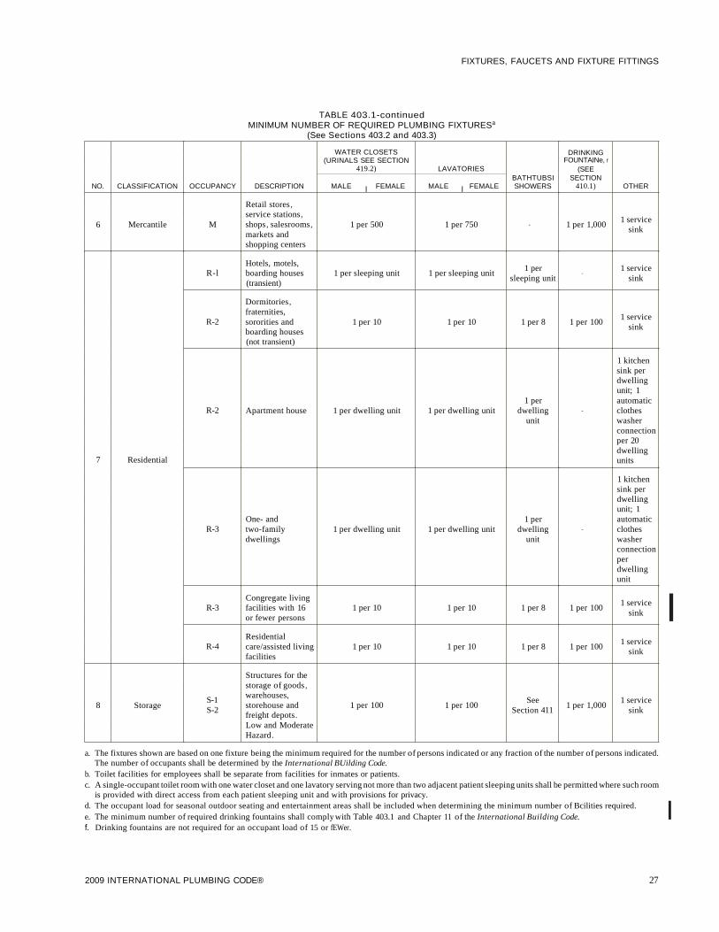
FIXTURES, FAUCETS AND FIXTURE FITTINGS
TABLE 403.1-continuedMINIMUM NUMBER OF REQUIRED PLUMBING FIXTURESa
(See Sections 403.2 and 403.3)
WATER CLOSETS DRINKING(URINALS SEE SECTION FOUNTAINe, f
419.2) LAVATORIES (SEE
I IBATHTUBSI SECTION
NO. CLASSIFICATION OCCUPANCY DESCRIPTION MALE FEMALE MALE FEMALE SHOWERS 410.1) OTHER
Retail stores,service stations,
1 service6 Mercantile M shops, salesrooms, 1 per 500 1 per 750 - 1 per 1,000
sinkmarkets andshopping centers
Hotels, motels,1 per 1 service
R-l boarding houses 1 per sleeping unit 1 per sleeping unitsleeping unit
-sink
(transient)
Dormitories,fraternities,
1 serviceR-2 sororities and 1 per 10 1 per 10 1 per 8 1 per 100
sinkboarding houses(not transient)
1 kitchensink perdwellingunit; 1
1 per automaticR-2 Apartment house 1 per dwelling unit 1 per dwelling unit dwelling - clothes
unit washerconnectionper 20dwelling
7 Residential units
1 kitchensink perdwellingunit; 1
One- and 1 per automaticR-3 two-family 1 per dwelling unit 1 per dwelling unit dwelling - clothes
dwellings unit washerconnectionperdwellingunit
Congregate living1 service
R-3 facilities with 16 1 per 10 1 per 10 1 per 8 1 per 100sink
or fewer persons
Residential1 service
R-4 care/assisted living 1 per 10 1 per 10 1 per 8 1 per 100sink
facilities
Structures for thestorage of goods,
S-1warehouses,
See 1 service8 Storage S-2
storehouse and 1 per 100 1 per 100Section 411
1 per 1,000sink
freight depots.Low and ModerateHazard.
I
a. The fixtures shown are based on one fixture being the minimum required for the number of persons indicated or any fraction of the number of persons indicated.The number of occupants shall be determined by the International BUilding Code.
b. Toilet facilities for employees shall be separate from facilities for inmates or patients.c. A single-occupant toilet room with one water closet and one lavatory serving not more than two adjacent patient sleeping units shall be permitted where such room
is provided with direct access from each patient sleeping unit and with provisions for privacy.d. The occupant load for seasonal outdoor seating and entertainment areas shall be included when determining the minimum number of Bcilities required.e. The minimum number of required drinking fountains shall comply with Table 403.1 and Chapter 11 of the International Building Code. If. Drinking fountains are not required for an occupant load of 15 or fEWer.
2009 INTERNATIONAL PLUMBING CODE® 27

FIXTURES, FAUCETS AND FIXTURE FITTINGS
403.1.1 Fixture calculations. To determine the occupantload of each sex, the total occupant load shall be divided inhalf. To determine the required number of fixtures, the fixture ratio or ratios for each fixture type shall be applied tothe occupant load of each sex in accordance with Table403.1. Fractional numbers resulting from applying the fixture ratios of Table 403.1 shall be rounded up to the nextwhole number. For calculations involving multiple occupancies, such fractional numbers for each occupancy shallfirst be summed and then rounded up to the next whole number.
Exception: The total occupant load shall not be requiredto be divided in half where approvedstatistical data indicates a distribution of the sexes of other than 50 percentof each sex.
403.1.2 Family or assisted-use toilet and bath fixtures.Fixtures located within family or assisted-use toilet andbathing rooms required by Section 1109.2.1 of the International BUilding Code are permitted to be included in thenumber of required fixtures for either the male or femaleoccupants in assembly and mercantile occupancies.
403.2 Separate facilities. Where plumbing fixtures arerequired, separate facilities shall be provided for each sex.
Exceptions:
1. Separate facilities shall not be required for dwellingunits and sleeping units.
2. Separate facilities shall not be required in structuresor tenant spaces with a total occupant load, includingboth employees and customers, of 15 or less.
3. Separate facilities shall not be required in mercantileoccupancies in which the maximum occupant load is50 or less.• 403.3 Required public toilet facilities. Customers, patrons
and visitors shall be provided with public toilet facilities instructures and tenant spaces intended for public utilization. Thenumber of plumbing fixtures located within the required toiletfacilities shall be provided in accordance with Section 403 forall users. Employees shall be provided with toilet facilities inall occupancies. Employee toilet facilities shall be either separate or combined employee and public toilet facilities.
403.3.1 Access. The route to the public toilet facilitiesrequired by Section 403.3 shall not pass through kitchens,storage rooms or closets. Access to the required facilitiesshall be from within the building or from the exterior of thebuilding. All routes shall comply with the accessibilityrequirements of the International Building Code. The public shall have access to the required toilet facilities at alltimes that the building is occupied.
403.3.2 Location of toilet facilities in occupancies otherthan covered malls. In occupancies other than coveredmall buildings, the required public and employee toiletfacilities shall be located not more than one story above orbelow the space required to be provided with toilet facilities,
28
and the path of travel to such facilities shall not exceed a distance of 500 feet (152m).
Exception: The location and maximum travel distancesto required employee facilities in factory and industrialoccupancies are permitted to exceed that required by thissection, provided that the location and maximum traveldistance are approved.
403.3.3 Location of toilet facilities in covered malls. Incovered mall buildings, the required public and employeetoilet facilities shall be located not more than one storyabove or below the space required to be provided with toiletfacilities, and the path of travel to such facilities shall notexceed a distance of 300 feet (91 440 mm). In covered mallbuildings, the required facilities shall be based on totalsquare footage, and facilities shall be installed in each individual store or in a central toilet area located in accordancewith this section. The maximum travel distance to centraltoilet facilities in covered mall buildings shall be measuredfrom the main entrance of any store or tenant space. In covered mall buildings, where employees' toilet facilities arenot provided in the individual store, the maximum traveldistance shall be measured from the employees' work areaof the store or tenant space.
403.3.4 Pay facilities. Where pay facilities are installed,such facilities shall be in excess of the required minimumfacilities. Required facilities shall be free of charge.
403.4 Signage. Required public facilities shall be designatedby a legible sign for each sex. Signs shall be readily visible andlocated near the entrance to each toilet facility.
403.4.1 Directional signage. Directional signage indicating the route to the public facilities shall be posted in accordance with Section 3107 of the International BuildingCode. Such signage shall be located in a corridor or aisle, atthe entrance to the facilities for customers and visitors.
SECTION 404ACCESSIBLE PLUMBING FACILITIES
404.1 Where required. Accessible plumbing facilities andfixtures shall be provided in accordance with the InternationalBUilding Code.
SECTION 405INSTALLATION OF FIXTURES
405.1 Water supply protection. The supply lines and fittingsfor every plumbing fixture shall be installed so as to preventbackflow.
405.2 Access for cleaning. Plumbing fixtures shall be installedso as to afford easy access for cleaning both the fixture and thearea around the fixture.
405.3 Setting. Fixtures shall be set level and in proper alignment with reference to adjacent walls.
405.3.1 Water closets, urinals, lavatories and bidets. Awater closet, urinal, lavatory or bidet shall not be set closer
2009 INTERNATIONAL PLUMBING CODE®

FIXTURES, FAUCETS AND FIXTURE FITTINGS
For 51: 1 inch = 25.4 mm.
FIGURE 405.3.1FIXTURE CLEARANCE
G\ COMPARTMENT
406.1 Approval. Domestic automatic clothes washers shallconform to ASSE 1007.
SECTION 406AUTOMATIC CLOTHES WASHERS
405.9 Design and installation of plumbing fixtures. Integralfixture fitting mounting surfaces on manufactured plumbingfixtures or plumbing fixtures constructed on site, shall meet thedesign requirements of ASME A 112 .19. 2M or ASMEAl12.19.3M.
405.8 Slipjoint connections. Slip joints shall be made with anapproved elastomeric gasket and shall only be installed on thetrap outlet, trap inlet and within the trap seal. Fixtures with concealed slip-joint connections shall be provided with an accesspanel or utility space at least 12 inches (305 mm) in its smallestdimension or other approved arrangement so as to provideaccess to the slip joint connections for inspection and repair.
405.5 Water-tight joints. Joints formed where fixtures comein contact with walls or floors shall be sealed.
cealed metal carrier that is attached to the building structuralmembers so that strain is not transmitted to the closet connector or any other part of the plumbing system. The carriershall conform to ASME Al12.6.1M or ASME Al12.6.2.
405.6 Plumbing in mental health centers. In mental healthcenters, pipes or traps shall not be exposed, and fixtures shallbe bolted through walls.
405.7 Design ofoverflows. Where any fixture is provided withan overflow, the waste shall be designed and installed so thatstanding water in the fixture will not rise in the overflow whenthe stopper is closed, and no water will remain in the overflowwhen the fixture is empty.
405.7.1 Connection of overflows. The overflow from anyfixture shall discharge into the drainage system on the inletor fixture side of the trap.
Exception: The overflow from a flush tank serving awater closet or urinal shall discharge into the fixtureserved.
406.3 Waste connection. The waste from an automatic clotheswasher shall discharge through an air break into a standpipe inaccordance with Section 802.4 or into a laundry sink. The trapand fixture drain for an automatic clothes washer standpipeshall be a minimum of 2 inches (51 mm) in diameter. The automatic clothes washer fixture drain shall connect to a branchdrain or drainage stack a minimum of 3 inches (76 mm) indiameter. Automatic clothes washers that discharge by gravityshall be permitted to drain to a waste receptor or an approvedtrench drain.
406.2 Water connection. The water supply to an automaticclothes washer shall be protected against backflow by an airgap installed integrally within the machine conforming toASSE 1007 or with the installation of a backflow preventer inaccordance with Section 608.
21 IN.CLEARANCE
than 15 inches (381 mm) from its center to any side wall,partition, vanity or other obstruction, or closer than 30inches (762 mm) center-to-center between adjacent fixtures. There shall be at least a 21-inch (533 mm) clearance infront of the water closet, urinal, lavatory or bidet to any wall,fixture or door. Water closet compartments shall not be lessthan 30 inches (762 mm) wide and 60 inches (1524 mm)deep (see Figure 405.3.1).
21 IN.CLEARANCE
405.3.2 Public lavatories. In employee and public toiletrooms, the required lavatory shall be located in the sameroom as the required water closet.
405.4 Floor and wall drainage connections. Connectionsbetween the drain and floor outlet plumbing fixtures shall bemade with a floor flange. The flange shall be attached to thedrain and anchored to the structure. Connections between thedrain and wall-hung water closets shall be made with anapproved extension nipple or horn adaptor. The water closetshall be bolted to the hanger with corrosion-resistant bolts orscrews. Joints shall be sealed with an approved elastomericgasket, flange-to-fixture connection complying with ASMEAl12.4.3 or an approved setting compound.
405.4.1 Floor flanges. Floor flanges for water closets orsimilar fixtures shall not be less than 0.125 inch (3.2 mm)thick for brass, 0.25 inch (6.4 mm) thick for plastic, and 0.25inch (6.4 mm) thick and not less than a 2-inch (51 mm)caulking depth for cast-iron or galvanized malleable iron.
Floor flanges of hard lead shall weigh not less than 1pound, 9 ounces (0.7 kg) and shall be composed of leadalloy with not less than 7.75-percent antimony by weight.Closet screws and bolts shall be of brass. Flanges shall besecured to the building structure with corrosion-resistantscrews or bolts.
405.4.2 Securing floor outlet fixtures. Floor outlet fixturesshall be secured to the floor or floor flanges by screws orbolts of corrosion-resistant material.
405.4.3 Securing wall-hung water closet bowls.Wall-hung water closet bowls shall be supported by a con-
2009 INTERNATIONAL PLUMBING CODE® 29
FIXTURES, FAUCETS AND FIXTURE FITTINGS
SECTION 407BATHTUBS
407.1 Approval. Bathtubs shall conform to ANSI ZI24.1,ASME AI12.19.1M, ASME AI12.19.4M, ASMEAI12.19.9M, CSA B45.2, CSA B45.3 or CSA B45.5.
407.2 Bathtub waste outlets. Bathtubs shall have waste outlets a minimum of 11/ 2 inches (38 mm) in diameter. The wasteoutlet shall be equipped with an approved stopper.
407.3 Glazing. Windows and doors within a bathtub enclosureshall conform to the safety glazing requirements of the International Building Code.
407.4 Bathtub enclosure. Doors within a bathtub enclosureshall conform to ASME AI12.19.15.
SECTION 408BIDETS
408.1 Approval. Bidets shall conform to ASME AI12.19.2M,ASME AI12.19.9M or CSA B45.1.
408.2 Water connection. The water supply to a bidet shall beprotected against backflow by an airgap or backflow preventerin accordance with Section 608.13.1, 608.13.2, 608.13.3,608.13.5,608.13.6 or 608.13.8.
408.3 Bidet water temperature. The discharge water temperature from a bidet fitting shall be limited to a maximum temperature of 110°F (43°C) by a water temperature limiting deviceconforming to ASSE 1070.
SECTION 409DISHWASHING MACHINES
409.1 Approval. Domestic dishwashing machines shall conform to ASSE 1006. Commercial dishwashing machines shallconform to ASSE 1004 and NSF 3.
409.2 Water connection. The water supply to a dishwashingmachine shall be protected against backflow by an air gap orbackflow preventer in accordance with Section 608.
409.3 Waste connection. The waste connection of adishwashing machine shall comply with Section 802.1.6 or802.1.7, as applicable.
SECTION 410DRINKING FOUNTAINS
410.1 Approval. Drinking fountains shall conform to ASMEAI12.19.1M, ASME AI12.19.2M or ASME AI12.19.9M andwater coolers shall conform to ARI 1010. Drinking fountainsand water coolers shall conform to NSF 61, Section 9. Wherewater is served in restaurants, drinking fountains shall not berequired. In other occupancies, where drinking fountains arerequired, water coolers or bottled water dispensers shall be permitted to be substituted for not more than 50 percent of therequired drinking fountains.
I 410.2 Prohibited location. Drinking fountains, water coolersand bottled water dispensers shall not be installed in publicrestrooms.
30
SECTION 411EMERGENCY SHOWERS AND
EYEWASH STATIONS
411.1 Approval. Emergency showers and eyewash stationsshall conform to ISEA Z358.1.
411.2 Waste connection. Waste connections shall not berequired for emergency showers and eyewash stations.
SECTION 412FLOOR AND TRENCH DRAINS
412.1 Approval. Floor drains shall conform to ASMEAI12.3.1, ASME AI12.6.3 or CSA B79. Trench drains shallcomply with ASME AI12.6.3.
412.2 Floor drains. Floor drains shall have removeable strainers. The floor drain shall be constructed so that the drain iscapable of being cleaned. Access shall be provided to the draininlet. Ready access shall be provided to floor drains.
Exception: Floor drains serving refrigerated display casesshall be provided with access.
412.3 Size of floor drains. Floor drains shall have a minimum2-inch-diameter (51 mm) drain outlet.
412.4 Public laundries and central washing facilities. Inpublic coin-operated laundries and in the central washing facilities of multiple-family dwellings, the rooms containing automatic clothes washers shall be provided with floor drainslocated to readily drain the entire floor area. Such drains shallhave a minimum outlet of not less than 3 inches (76 mm) indiameter.
SECTION 413FOOD WASTE GRINDER UNITS
413.1 Approval. Domestic food waste grinders shall conformto ASSE 1008. Commercial food waste grinders shall conformto ASSE 1009. Food waste grinders shall not increase thedrainage fixture unit load on the sanitary drainage system.
413.2 Domestic food waste grinder waste outlets. Domesticfood waste grinders shall be connected to a drain of not lessthan 11/ 2 inches (38 mm) in diameter.
413.3 Commercial food waste grinder waste outlets. Commercial food waste grinders shall be connected to a drain notless than 11/ 2 inches (38 mm) in diameter. Commercial foodwaste grinders shall be connected and trapped separately fromany other fixtures or sink compartments.
413.4 Water supply required. All food waste grinders shall beprovided with a supply of cold water. The water supply shall beprotected against backflow by an airgap or backflow preventerin accordance with Section 608.
SECTION 414GARBAGE CAN WASHERS
414.1 Water connection. The water supply to a garbage canwasher shall be protected against backflow by an air gap or a
2009 INTERNATIONAL PLUMBING CODE®

backflow preventer in accordance with Section 608.13.1,608.13.2,608.13.3,608.13.5,608.13.6 or 608.13.8.
414.2 Waste connection. Garbage can washers shall betrapped separately. The receptacle receiving the waste from thewasher shall have a removable basket or strainer to prevent thedischarge of large particles into the drainage system.
SECTION 415LAUNDRY TRAYS
415.1 Approval. Laundry trays shall conform to ANSIZ124.6, ASME Al12.19.1M, ASME Al12.19.3M, ASMEAl12.19.9M, CSA B45.2 or CSA B45.4.
415.2 Waste outlet. Each compartment of a laundry tray shallbe provided with a waste outlet a minimum of 11/ 2 inches (38mm) in diameter and a strainer or crossbar to restrict the clearopening of the waste outlet.
SECTION 416LAVATORIES
416.1 Approval. Lavatories shall conform to ANSI Z124.3,ASME Al12.19.1M, ASME Al12.19.2M, ASMEAl12.19.3M, ASME Al12.19.4M, ASME Al12.19.9M, CSAB45.1, CSA B45.2, CSAB45.3 or CSA B45.4. Group wash-upequipment shall conform to the requirements of Section 402 .Every 20 inches (508 mm) of rim space shall be considered asone lavatory.
416.2 Cultured marble lavatories. Cultured marble vanitytops with an integral lavatory shall conform to ANSI Z124.3 orCSA B45.5.
416.3 Lavatory waste outlets. Lavatories shall have wasteoutlets not less than 11/ 4 inches (32 mm) in diameter. A strainer,pop-up stopper, crossbar or other device shall be provided torestrict the clear opening of the waste outlet.
416.4 Moveable lavatory systems. Moveable lavatory systems shall comply with ASME Al12.19.12.
416.5 Tempered water for public hand-washing facilities.Tempered water shall be delivered from public hand-washingfacilities. Tempered water shall be delivered through anapproved water-temperature limiting device that conforms toASSE 1070 or CSA B125.3.
SECTION 417SHOWERS
417.1 Approval. Prefabricated showers and shower compartments shall conform to ANSI Z124.2, ASME Al12.19.9M orCSA B45.5. Shower valves for individual showers shall conform to the requirements of Section 424.3.
417.2 Water supply riser. Water supply risers from the showervalve to the shower head outlet, whether exposed or concealed,shall be attached to the structure. The attachment to the structure shall be made by the use of support devices designed foruse with the specific piping material or by fittings anchoredwith screws.
2009 INTERNATIONAL PLUMBING CODE®
FIXTURES, FAUCETS AND FIXTURE FITTINGS
417.3 Shower waste outlet. Waste outlets serving showersshall be at least 11/ 2 inches (38 mm) in diameter and, for otherthan waste outlets in bathtubs, shall have removable strainersnot less than 3 inches (76 mm) in diameter with strainer openings not less than 1/4 inch (6.4 mm) in minimum dimension.Where each shower space is not provided with an individualwaste outlet, the waste outlet shall be located and the floorpitched so that waste from one shower does not flow over thefloor area serving another shower. Waste outlets shall be fastened to the waste pipe in an approved manner.
417.4 Shower compartments. All shower compartments shallhave a minimum of 900 square inches (0.58 m2) of interiorcross-sectional area. Shower compartments shall not be lessthan 30 inches (762 mm) in minimum dimension measuredfrom the finished interior dimension of the compartment,exclusive of fixture valves, showerheads, soap dishes, andsafety grab bars or rails. Except as required in Section 404, theminimum required area and dimension shall be measured fromthe finished interior dimension at a height equal to the top ofthethreshold and at a point tangent to its centerline and shall becontinued to a height not less than 70 inches (1778 mm) abovethe shower drain outlet.
Exception: Shower compartments having not less than 25inches (635 mm) in minimum dimension measured from thefinished interior dimension of the compartment, providedthat the shower compartment has a minimum of 1,300square inches (.838 m2) of cross-sectional area.
417.4.1 Wall area. The wall area above built-in tubs withinstalled shower heads and in shower compartments shall beconstructed of smooth, noncorrosive and nonabsorbentwaterproof materials to a height not less than 6 feet (1829mm) above the room floor level, and not less than 70 inches(1778 mm) where measured from the compartment floor atthe drain. Such walls shall form a water-tightjoint with eachother and with either the tub, receptor or shower floor.
417.4.2 Access. The shower compartment access and egressopening shall have a minimum clear and unobstructed finished width of 22 inches (559 mm). Shower compartmentsrequired to be designed in conformance to accessibility provisions shall comply with Section 404.1.
417.5 Shower floors or receptors. Floor surfaces shall be constructed of impervious, noncorrosive, nonabsorbent and waterproof materials.
417.5.1 Support. Floors or receptors under shower compartments shall be laid on, and supported by, a smooth andstructurally sound base.
417.5.2 Shower lining. Floors under shower compartments, except where prefabricated receptors have been provided, shall be lined and made water tight utilizing materialcomplying with Sections 417.5.2.1 through 417.5.2.5. Suchliners shall turn up on all sides at least 2 inches (51 mm)above the finished threshold level. Liners shall be recessedand fastened to an approved backing so as not to occupy thespace required for wall covering, and shall not be nailed orperforated at any point less than 1 inch (25 mm) above thefinished threshold. Liners shall be pitched one-fourth unit
31

I
FIXTURES, FAUCETS AND FIXTURE FITTINGS
vertical in 12 units horizontal (2-percent slope) and shall besloped toward the fixture drains and be securely fastened tothe waste outlet at the seepage entrance, making awater-tight joint between the liner and the outlet. The completed liner shall be tested in accordance with Section 312.9.
Exceptions:
1. Floor surfaces under shower heads provided forrinsing laid directly on the ground are not requiredto comply with this section.
2. Where a sheet-applied, load-bearing, bonded,waterproof membrane is installed as the showerlining, the membrane shall not be required to berecessed.
417.5.2.1 PVC sheets. Plasticized polyvinyl chloride(PVC) sheets shall be a minimum of 0.040 inch (1.02mm) thick, and shall meet the requirements of ASTM D4551. Sheets shall be joined by solvent welding in accordance with the manufacturer's installation instructions.
417.5.2.2 Chlorinated polyethylene (CPE) sheets.Nonplasticized chlorinated polyethylene sheet shall be aminimum 0.040 inch (1.02 mm) thick, and shall meet therequirements of ASTM D 4068. The liner shall be joinedin accordance with the manufacturer's installationinstructions.
417.5.2.3 Sheet lead. Sheet lead shall not weigh lessthan 4 pounds per square foot (19.5 kg/m2) coated withan asphalt paint or other approved coating. The leadsheet shall be insulated from conducting substancesother than the connecting drain by IS-pound (6.80 kg)asphalt felt or its equivalent. Sheet lead shall bejoined byburning.
417.5.2.4 Sheet copper. Sheet copper shall conform toASTM B 152 and shall not weigh less than 12 ounces persquare foot (3.7 kg/m2). The copper sheet shall be insulated from conducting substances other than the connecting drain by IS-pound (6.80 kg) asphalt felt or itsequivalent. Sheet copper shall be joined by brazing orsoldering.
417.5.2.5 Sheet-applied, load-bearing, bonded,waterproof membranes. Sheet-applied, load-bearing,bonded, waterproof membranes shall meet requirementsof ANSI Al18.10 and shall be applied in accordancewith the manufacturer's installation instructions.
417.6 Glazing. Windows and doors within a shower enclosureshall conform to the safety glazing requirements of the International Building Code.
SECTION 418SINKS
418.1 Approval. Sinks shall conform to ANSI Z124.6, ASMEAl12.19.1M, ASME Al12.19.2M, ASME Al12.19.3M,ASME Al12.19.4M, ASME Al12.19.9M, CSA B45.1, CSAB45.2, CSA B45.3 or CSA B45.4.
32
418.2 Sink waste outlets. Sinks shall be provided with wasteoutlets a minimum of 11/ 2 inches (38 mm) in diameter. Astrainer or crossbar shall be provided to restrict the clear opening of the waste outlet.
418.3 Moveable sink systems. Moveable sink systems shallcomply with ASME Al12.19.12.
SECTION 419URINALS
419.1 Approval. Urinals shall conform to ANSI Z124.9,ASME Al12.19.2M, ASME Al12.19.19, CSA B45.1 or CSAB45.5. Urinals shall conform to the water consumptionrequirements of Section 604.4. Water-supplied urinals shallconform to the hydraulic performance requirements of ASMEAl12.19.6, CSA B45.1 or CSA B45.5.
419.2 Substitution for water closets. In each bathroom or toilet room, urinals shall not be substituted for more than 67 percent of the required water closets in assembly and educationaloccupancies. Urinals shall not be substituted for more than 50percent of the required water closets in all other occupancies.
[B] 419.3 Surrounding material. Wall and floor space to apoint 2 feet (610 mm) in front of a urinal lip and 4 feet (1219mm) above the floor and at least 2 feet (610 mm) to each side ofthe urinal shall be waterproofed with a smooth, readilycleanable, nonabsorbent material.
SECTION 420WATER CLOSETS
420.1 Approval. Water closets shall conform to the water consumption requirements of Section 604.4 and shall conform toANSI Z124.4, ASME Al12.19.2M, CSA B45.1, CSA B45.4or CSA B45.5. Water closets shall conform to the hydraulicperformance requirements of ASME Al12.19.6. Water closettanks shall conform to ANSI Z124.4, ASME Al12.19.2,ASME Al12.19.9M, CSA B45.1, CSA B45.4 or CSA B45.5.Electro-hydraulic water closets shall comply with ASMEAl12.19.13.
420.2 Water closets for public or employee toilet facilities.Water closet bowls for public or employee toilet facilities shallbe of the elongated type.
420.3 Water closet seats. Water closets shall be equipped withseats of smooth, nonabsorbent material. All seats ofwater closets provided for public or employee toilet facilities shall be ofthe hinged open-front type. Integral water closet seats shall beof the same material as the fixture. Water closet seats shall besized for the water closet bowl type.
420.4 Water closet connections. A 4-inch by 3-inch (102 mmby 76 mm) closet bend shall be acceptable. Where a 3-inch (76mm) bend is utilized on water closets, a 4-inch by 3-inch (102mm by 76 mm) flange shall be installed to receive the fixturehorn.
2009 INTERNATIONAL PLUMBING CODE®

SECTION 421WHIRLPOOL BATHTUBS
421.1 Approval. Whirlpool bathtubs shall comply with ASMEAl12.19.7M or with CSA B45.5 and CSA B45 (Supplement1) .
421.2 Installation. Whirlpool bathtubs shall be installed andtested in accordance with the manufacturer's installationinstructions. The pump shall be located above the weir of thefixture trap.
421.3 Drain. The pump drain and circulation piping shall besloped to drain the water in the volute and the circulation pipingwhen the whirlpool bathtub is empty.
421.4 Suction fittings. Suction fittings for whirlpool bathtubsshall comply with ASME Al12 .19.8M.
421.5 Access to pump. Access shall be provided to circulationpumps in accordance with the fixture or pump manufacturer'sinstallation instructions. Where the manufacturer's instructions do not specify the location and minimum size offield-fabricated access openings, a 12-inch by 12-inch (305 mm by 305mm) minimum sized opening shall be installed to provideaccess to the circulation pump. Where pumps are located morethan 2 feet (609 mm) from the access opening, an 18-inch by18-inch (457 mm by 457 mm) minimum sized opening shall beinstalled. A door or panel shall be permitted to close the opening. In all cases, the access opening shall be unobstructed andof the size necessary to permit the removal and replacement ofthe circulation pump.
421.6 Whirlpool enclosure. Doors within a whirlpool enclosure shall conform to ASME A112.19.15.
SECTION 422HEALTH CARE FIXTURES AND EQUIPMENT
422.1 Scope. This section shall govern those aspects of healthcare plumbing systems that differ from plumbing systems inother structures. Health care plumbing systems shall conformto the requirements of this section in addition to the otherrequirements of this code. The provisions of this section shallapply to the special devices and equipment installed and maintained in the following occupancies: nursing homes, homes forthe aged, orphanages, infirmaries, first aid stations, psychiatricfacilities, clinics, professional offices of dentists and doctors,mortuaries, educational facilities, surgery, dentistry, researchand testing laboratories, establishments manufacturing pharmaceutical drugs and medicines, and other structures with similar apparatus and equipment classified as plumbing.
422.2 Approval. All special plumbing fixtures, equipment,devices and apparatus shall be of an approved type.
422.3 Protection. All devices, appurtenances, appliances andapparatus intended to serve some special function, such as sterilization, distillation, processing, cooling, or storage of ice orfoods, and that connect to either the water supply or drainagesystem, shall be provided with protection against backflow,flooding, fouling, contamination of the water supply systemand stoppage of the drain.
422.4 Materials. Fixtures designed for therapy, special cleansing or disposal of waste materials, combinations of such pur-
2009 INTERNATIONAL PLUMBING CODE®
FIXTURES, FAUCETS AND FIXTURE FITTINGS
poses, or any other special purpose, shall be of smooth, impervious, corrosion-resistant materials and, where subjected totemperatures in excess of 180°F (82°C), shall be capable ofwithstanding, without damage, higher temperatures.
422.5 Access. Access shall be provided to concealed piping inconnection with special fixtures where such piping containssteam traps, valves, relief valves, check valves, vacuum breakers or other similar items that require periodic inspection, servicing, maintenance or repair. Access shall be provided toconcealed piping that requires periodic inspection, maintenance or repair.
422.6 Clinical sink. A clinical sink shall have an integral trapin which the upper portion ofa visible trap seal provides a watersurface. The fixture shall be designed so as to permit completeremoval of the contents by siphonic or blowout action and toreseal the trap. A flushing rim shall provide water to cleanse theinterior surface. The fixture shall have the flushing and cleansing characteristics of a water closet.
422.7 Prohibited usage ofclinical sinks and service sinks. Aclinical sink serving a soiled utility room shall not be considered as a substitute for, or be utilized as, a service sink. A service sink shall not be utilized for the disposal of urine, fecalmatter or other human waste.
422.8 Ice prohibited in soiled utility room. Machines formanufacturing ice, or any device for the handling or storage ofice, shall not be located in a soiled utility room.
422.9 Sterilizer equipment requirements. The approval andinstallation of all sterilizers shall conform to the requirementsof the International Mechanical Code.
422.9.1 Sterilizer piping. Access for the purposes ofinspection and maintenance shall be provided to all sterilizer piping and devices necessary for the operation of sterilizers.
422.9.2 Steam supply. Steam supplies to sterilizers, including those connected by pipes from overhead mains orbranches, shall be drained to prevent any moisture fromreaching the sterilizer. The condensate drainage from thesteam supply shall be discharged by gravity.
422.9.3 Steam condensate return. Steam condensatereturns from sterilizers shall be a gravity return system.
422.9.4 Condensers. Pressure sterilizers shall be equippedwith a means of condensing and cooling the exhaust steamvapors. Nonpressure sterilizers shall be equipped with adevice that will automatically control the vapor, confiningthe vapors within the vessel.
422.10 Special elevations. Control valves, vacuum outlets anddevices protruding from a wall of an operating, emergency,recovery, examining or delivery room, or in a corridor or otherlocation where patients are transported on a wheeled stretcher,shall be located at an elevation that prevents bumping thepatient or stretcher against the device.
33

1
FIXTURES, FAUCETS AND FIXTURE FITTINGS
SECTION 423SPECIALTY PLUMBING FIXTURES
423.1 Water connections. Baptisteries, ornamental and lilypools, aquariums, ornamental fountain basins, swimmingpools, and similar constructions, where provided with watersupplies, shall be protected against backflow in accordancewith Section 608.
423.2 Approval. Specialties requiring water and waste connections shall be submitted for approval.
SECTION 424FAUCETS AND OTHER FIXTURE FITTINGS
424.1 Approval. Faucets and fixture fittings shall conform toASME Al12.18.1/CSA B125.1. Faucets and fixture fittingsthat supply drinking water for human ingestion shall conformto the requirements of NSF 61, Section 9. Flexible water connectors exposed to continuous pressure shall conform to therequirements of Section 605.6.
424.1.1 Faucets and supply fittings. Faucets and supplyfittings shall conform to the water consumption requirements of Section 604.4.
424.1.2 Waste fittings. Waste fittings shall conform toASME Al12.18.2/CSA B125.2, ASTM F 409 or to one ofthe standards listed in Tables 702.1 and 702.4 forabove-ground drainage and vent pipe and fittings.
424.2 Hand showers. Hand-held showers shall conform toASME Al12.18.1 or CSA B125.1. Hand-held showers shallprovide backflow protection in accordance with ASMEAl12.18.1 or CSA B125.1 or shall be protected againstbackflow by a device complying with ASME Al12.18.3.
424.3 Individual shower valves. Individual shower andtub-shower combination valves shall be balanced-pressure,thermostatic or combination balanced-pressure/thermostaticvalves that conform to the requirements of ASSE 1016 orASME Al12.18.1/CSA B125.1 and shall be installed at thepoint of use. Shower and tub-shower combination valvesrequired by this section shall be equipped with a means to limitthe maximum setting of the valve to 120°F (49°C), which shallbe field adjusted in accordance with the manufacturer'sinstructions. In-line thermostatic valves shall not be utilized forcompliance with this section.
424.4 Multiple (gang) showers. Multiple (gang) showers supplied with a single-tempered water supply pipe shall have thewater supply for such showers controlled by an approvedautomatic temperature control mixing valve that conforms to ASSE1069 or CSA B125, or each shower head shall be individuallycontrolled by a balanced-pressure, thermostatic or combination balanced-pressure/thermostatic valve that conforms toASSE 1016 or CSA B125 and is installed at the point of use.Such valves shall be equipped with a means to limit the maximum setting of the valve to 120°F (49°C), which shall be fieldadjusted in accordance with the manufacturer's instructions.
1424.5 Bathtub and whirlpool bathtub valves. The hot watersupplied to bathtubs and whirlpool bathtubs shall be limited toa maximum temperature of 120°F (49°C) by a water-temperature limiting device that conforms to ASSE 1070 or CSA
34
B125.3, except where such protection is otherwise provided by Ia combination tub/shower valve in accordance with Section424.3.
424.6 Hose-connected outlets. Faucets and fixture fittingswith hose-connected outlets shall conform to ASMEAl12.18.3M or CSA B125.
424.7 Temperature-actuated, flow reduction valves forindividual fixture fittings. Temperature-actuated, flow reduction devices, where installed for individual fixture fittings,shall conform to ASSE 1062. Such valves shall not be usedalone as a substitute for the balanced pressure, thermostatic orcombination shower valves required in Section 424.3.
424.8 Transfer valves. Deck-mounted bath/shower transfervalves containing an integral atmospheric vacuum breakershall conform to the requirements of ASME Al12 .18.7.
SECTION 425FLUSHING DEVICES FOR
WATER CLOSETS AND URINALS
425.1 Flushing devices required. Each water closet, urinal,clinical sink and any plumbing fixture that depends on trapsiphonage to discharge the fixture contents to the drainage system shall be provided with a flushometer valve, flushometertank or a flush tank designed and installed to supply water inquantity and rate of flow to flush the contents of the fixture,cleanse the fixture and refill the fixture trap.
425.1.1 Separate for each fixture. A flushing device shallnot serve more than one fixture.
425.2 Flushometer valves and tanks. Flushometer valves andtanks shall comply with ASSE 1037. Vacuum breakers onflushometer valves shall conform to the performance requirements of ASSE 1001 or CAN/CSA B64.1.1. Access shall beprovided to vacuum breakers. Flushometer valves shall be ofthe water-conservation type and shall not be utilized where thewater pressure is lower than the minimum required for normaloperation. When operated, the valve shall automatically complete the cycle of operation, opening fully and closing positively under the water supply pressure. Each flushometer valveshall be provided with a means for regulating the flow throughthe valve. The trap seal to the fixture shall be automaticallyrefilled after each valve flushing cycle.
425.3 Flush tanks. Flush tanks equipped for manual flushingshall be controlled by a device designed to refill the tank aftereach discharge and to shut off completely the water flow to thetank when the tank is filled to operational capacity. The trapseal to the fixture shall be automatically refilled after eachflushing. The water supply to flush tanks equipped for automatic flushing shall be controlled with a timing device or sensor control devices.
425.3.1 Fill valves. All flush tanks shall be equipped withan antisiphon fill valve conforming to ASSE 1002 or CSAB125.3. The fill valve backflow preventer shall be located atleast 1 inch (25 mm) above the full opening of the overflowpipe.
425.3.2 Overflows in flush tanks. Flush tanks shall be provided with overflows discharging to the water closet or uri-
2009 INTERNATIONAL PLUMBING CODE®
nal connected thereto and shall be sized to prevent floodingthe tank at the maximum rate at which the tanks are suppliedwith water according to the manufacturer's design conditions. The opening of the overflow pipe shall be locatedabove the flood level rim of the water closet or urinal orabove a secondary overflow in the flush tank.
425.3.3 Sheet copper. Sheet copper utilized for flush tanklinings shall conform to ASTM B 152 and shall not weighless than 10 ounces per square foot (0.03 kg/m2).
425.3.4 Access required. All parts in a flush tank shall beaccessible for repair and replacement.
425.4 Flush pipes and fittings. Flush pipes and fittings shallbe of nonferrous material and shall conform to ASMEAl12.19.5 or CSA B125.
SECTION 426MANUAL FOOD AND BEVERAGE
DISPENSING EQUIPMENT
426.1 Approval. Manual food and beverage dispensing equipment shall conform to the requirements of NSF 18.
SECTION 427FLOOR SINKS
427.1 Approval. Sanitary floor sinks shall conform to therequirements of ASME Al12.6.7.
2009 INTERNATIONAL PLUMBING CODE®
FIXTURES, FAUCETS AND FIXTURE FITTINGS
35

36 2009 INTERNATIONAL PLUMBING CODE®

CHAPTER 5
WATER HEATERS
I
SECTION 501GENERAL
501.1 Scope. The provisions of this chapter shall govern thematerials, design and installation of water heaters and therelated safety devices and appurtenances.
501.2 Water heater as space heater. Where a combinationpotable water heating and space heating system requires waterfor space heating at temperatures higher than 140°F (60°C), amaster thermostatic mixing valve complying with ASSE 1017shall be provided to limit the water supplied to the potable hotwater distribution system to a temperature of 140°F (60°C) orless. The potability of the water shall be maintained throughoutthe system.
501.3 Drain valves. Drain valves for emptying shall beinstalled at the bottom of each tank-type water heater and hotwaterstorage tank. Drain valves shall conform to ASSE 1005.
501.4 Location. Water heaters and storage tanks shall belocated and connected so as to provide access for observation,maintenance, servicing and replacement.
501.5 Water heater labeling. All water heaters shall bethird-party certified.
501.6 Water temperature control in piping from tanklessheaters. The temperature of water from tankless water heatersshall be a maximum of 140°F (60°C) when intended fordomestic uses. This provision shall not supersede the requirement for protective shower valves in accordance with Section424.3.
501.7 Pressure marking of storage tanks. Storage tanks andwater heaters installed for domestic hot water shall have themaximum allowable working pressure clearly and indeliblystamped in the metal or marked on a plate welded thereto orotherwise permanently attached. Such markings shall be in anaccessible position outside of the tank so as to make inspectionor reinspection readily possible.
501.8 Temperature controls. All hot water supply systemsshall be equipped with automatic temperature controls capableof adjustments from the lowest to the highest acceptable temperature settings for the intended temperature operating range.
SECTION 502INSTALLATION
502.1 General. Water heaters shall be installed in accordancewith the manufacturer's installation instructions. Oil-firedwater heaters shall conform to the requirements of this codeand the International Mechanical Code. Electric water heatersshall conform to the requirements of this code and provisionsof NFPA 70. Gas-fired water heaters shall conform to therequirements of the International Fuel Gas Code.
502.1.1 Elevation and protection. Elevation of waterheater ignition sources and mechanical damage protection
2009 INTERNATIONAL PLUMBING CODE®
requirements for water heaters shall be in accordance with Ithe International Mechanical Code and the InternationalFuel Gas Code.
502.2 Rooms used as a plenum. Water heaters using solid, liquid or gas fuel shall not be installed in a room containingair-handling machinery when such room is used as a plenum.
502.3 Water heaters installed in attics. Attics containing awater heater shall be provided with an opening and unobstructed passageway large enough to allow removal of thewater heater. The passageway shall not be less than 30 inches(762 mm) high and 22 inches (559 mm) wide and not more than20 feet (6096 mm) in length when measured along the centerline of the passageway from the opening to the water heater.The passageway shall have continuous solid flooring not lessthan 24 inches (610 mm) wide. A level service space at least 30inches (762 mm) deep and 30 inches (762 mm) wide shall bepresent at the front or service side of the water heater. The clearaccess opening dimensions shall be a minimum of 20 inches by30 inches (508 mm by 762 mm) where such dimensions arelarge enough to allow removal of the water heater.
502.4 Seismic supports. Where earthquake loads are applicable in accordance with the International Building Code, waterheater supports shall be designed and installed for the seismicforces in accordance with the International Building Code.
502.5 Clearances for maintenance and replacement. Appliances shall be provided with access for inspection, service,repair and replacement without disabling the function of afire-resistance-rated assembly or removing permanent construction, other appliances or any other piping or ducts not connected to the appliance being inspected, serviced, repaired orreplaced. A level working space at least 30 inches deep and 30inches wide (762 mm by 762 mm) shall be provided in front ofthe control side to service an appliance.
SECTION 503CONNECTIONS
503.1 Cold water line valve. The cold water branch line fromthe main water supply line to each hot water storage tank orwater heater shall be provided with a valve, located near theequipment and serving only the hot water storage tank or waterheater. The valve shall not interfere or cause a disruption of thecold water supply to the remainder of the cold water system.The valve shall be provided with access on the same floor levelas the water heater served.
503.2 Water circulation. The method of connecting a circulating water heater to the tank shall provide proper circulation ofwater through the water heater. The pipe or tubes required forthe installation of appliances that will draw from the waterheater or storage tank shall comply with the provisions of thiscode for material and installation.
37

I
WATER HEATERS
SECTION 504SAFETY DEVICES
504.1 Antisiphon devices. An approvedmeans, such as a coldwater"dip" tube with a hole at the top or a vacuum relief valveinstalled in the cold water supply line above the top of theheater or tank, shall be provided to prevent siphoning of anystorage water heater or tank.
504.2 Vacuum reliefvalve. Bottom fed water heaters and bottom fed tanks connected to water heaters shall have a vacuumrelief valve installed. The vacuum relief valve shall complywith ANSI Z21.22.
504.3 Shutdown. A means for disconnecting an electric hotwater supply system from its energy supply shall be providedin accordance with NFPA 70. A separate valve shall be provided to shut off the energy fuel supply to all other types of hotwater supply systems.
504.4 Relief valve. All storage water heaters operating aboveatmospheric pressure shall be provided with an approved,self-closing (levered) pressure relief valve and temperaturerelief valve or combination thereof. The relief valve shall conform to ANSI Z21.22. The relief valve shall not be used as ameans of controlling thermal expansion.
504.4.1 Installation. Such valves shall be installed in theshell of the water heater tank. Temperature relief valvesshall be so located in the tank as to be actuated by the waterin the top 6 inches (152 mm) of the tank served. For installations with separate storage tanks, the valves shall beinstalled on the tank and there shall not be any type of valveinstalled between the water heater and the storage tank.There shall not be a check valve or shutoff valve between arelief valve and the heater or tank served.
504.5 Relief valve approval. Temperature and pressure reliefvalves, or combinations thereof, and energy cutoff devicesshall bear the label ofan approvedagency and shall have a temperature setting of not more than 210°F (99°C) and a pressuresetting not exceeding the tank or water heater manufacturer'srated working pressure or 150 psi (1035 kPa) , whichever isless. The relieving capacity of each pressure relief valve andeach temperature relief valve shall equal or exceed the heatinput to the water heater or storage tank.
504.6 Requirements for discharge piping. The dischargepiping serving a pressure relief valve, temperature relief valveor combination thereof shall:
1. Not be directly connected to the drainage system.
2. Discharge through an airgap located in the same roomas the water heater.
3. Not be smaller than the diameter of the outlet of thevalve served and shall discharge full size to the airgap.
4. Serve a single reliefdevice and shall not connect to piping serving any other relief device or equipment.
5. Discharge to the floor, to the pan serving the waterheater or storage tank, to a waste receptor or to the outdoors.
6. Discharge in a manner that does not cause personalinjury or structural damage.
38
7. Discharge to a termination point that is readily observable by the building occupants.
8. Not be trapped.
9. Be installed so as to flow by gravity.
10. Not terminate more than 6 inches (152 mm) above thefloor or waste receptor.
11. Not have a threaded connection at the end of such piping.
12. Not have valves or tee fittings.
13. Be constructed of those materials listed in Section605.4 or materials tested, rated and approved for suchuse in accordance with ASME AI12.4.1.
504.7 Required pan. Where water heaters or hot water storagetanks are installed in locations where leakage of the tanks orconnections will cause damage, the tank or water heater shallbe installed in a galvanized steel pan having a material thickness of not less than 0.0236 inch (0.6010 mm) (No. 24 gage), orother pans approved for such use.
504.7.1 Pan size and drain. The pan shall be not less than11/ 2 inches (38 mm) deep and shall be of sufficient size andshape to receive all dripping or condensate from the tank orwater heater. The pan shall be drained by an indirect wastepipe having a minimum diameter of 3/ 4 inch (19 mm). Pipingfor safety pan drains shall be of those materials listed inTable 605.4.
504.7.2 Pan drain termination. The pan drain shall extendfull-size and terminate over a suitably located indirect wastereceptor or floor drain or extend to the exterior of the building and terminate not less than 6 inches (152 mm) and notmore than 24 inches (610 mm) above the adjacent groundsurface.
SECTION 505INSULATION
[E] 505.1 Unfired vessel insulation. Unfired hot water storage Itanks shall be insulated to R-12.5 (h . ft2 • °F)/Btu (R-2.2 m2 •
K/W).
2009 INTERNATIONAL PLUMBING CODE®
CHAPTER 6
WATER SUPPLY AND DISTRIBUTION
SECTION 601GENERAL
601.1 Scope. This chapter shall govern the materials, designand installation of water supply systems, both hot and cold, forutilization in connection with human occupancy and habitationand shall govern the installation of individual water supply systems.
601.2 Solar energy utilization. Solar energy systems used forheating potable water or using an independent medium forheating potable water shall comply with the applicable requirements of this code. The use of solar energy shall not compromise the requirements for cross connection or protection of thepotable water supply system required by this code.
601.3 Existing piping used for grounding. Existing metallicwater service piping used for electrical grounding shall not bereplaced with nonmetallic pipe or tubing until other approvedmeans of grounding is provided.
601.4 Tests. The potable water distribution system shall betested in accordance with Section 312.5.
SECTION 602WATER REQUIRED
602.1 General. Every structure equipped with plumbing fixtures and utilized for human occupancy or habitation shall beprovided with a potable supply of water in the amounts and atthe pressures specified in this chapter.
602.2 Potable water required. Only potable water shall besupplied to plumbing fixtures that provide water for drinking,bathing or culinary purposes, or for the processing of food,medical or pharmaceutical products. Unless otherwise provided in this code, potable water shall be supplied to all plumbing fixtures.
602.3 Individual water supply. Where a potable public watersupply is not available, individual sources ofpotable water supply shall be utilized.
602.3.1 Sources. Dependent on geological and soil conditions and the amount of rainfall, individual water suppliesare of the following types: drilled well, driven well, dugwell, bored well, spring, stream or cistern. Surface bodies ofwater and land cisterns shall not be sources of individualwater supply unless properly treated by approved means toprevent contamination.
602.3.2 Minimum quantity. The combined capacity of thesource and storage in an individual water supply systemshall supply the fixtures with water at rates and pressures asrequired by this chapter.
602.3.3 Water quality. Water from an individual water supply shall be approved as potable by the authority havingjurisdiction prior to connection to the plumbing system.
2009 INTERNATIONAL PLUMBING CODE®
602.3.4 Disinfection of system. After construction ormajor repair, the individual water supply system shall bepurged of deleterious matter and disinfected in accordancewith Section 610.
602.3.5 Pumps. Pumps shall be rated for the transport ofpotable water. Pumps in an individual water supply systemshall be constructed and installed so as to prevent contamination from entering a potable water supply through thepump units. Pumps shall be sealed to the well casing or covered with a water-tight seal. Pumps shall be designed tomaintain a prime and installed such that ready access is provided to the pump parts of the entire assembly for repairs.
602.3.5.1 Pump enclosure. The pump room or enclosure around a well pump shall be drained and protectedfrom freezing by heating or other approved means.Where pumps are installed in basements, such pumpsshall be mounted on a block or shelf not less than 18inches (457 mm) above the basement floor. Well pitsshall be prohibited.
SECTION 603WATER SERVICE
603.1 Size ofwater service pipe. The water service pipe shallbe sized to supply water to the structure in the quantities and atthe pressures required in this code. The minimum diameter ofwater service pipe shall be 3/4 inch (19.1 mm).
603.2 Separation ofwater service and building sewer. Waterservice pipe and the building sewershall be separated by 5 feet(1524 mm) of undisturbed or compacted earth.
Exceptions:
1. The required separation distance shall not applywhere the bottom of the water service pipe within 5feet (1524 mm) of the sewer is a minimum of 12inches (305 mm) above the top of the highest point ofthe sewer and the pipe materials conform to Table702.3.
2. Water service pipe is permitted to be located in thesame trench with a bUilding sewer, provided suchsewer is constructed of materials listed in Table702.2.
3. The required separation distance shall not applywhere a water service pipe crosses a sewer pipe, provided the water service pipe is sleeved to at least 5 feet(1524 mm) horizontally from the sewer pipe centerline on both sides of such crossing with pipe materialslisted in Table 605.3, 702.2 or 702.3.
603.2.1 Water service near sources of pollution. Potablewater service pipes shall not be located in, under or abovecesspools, septic tanks, septic tank drainage fields or seep-
39
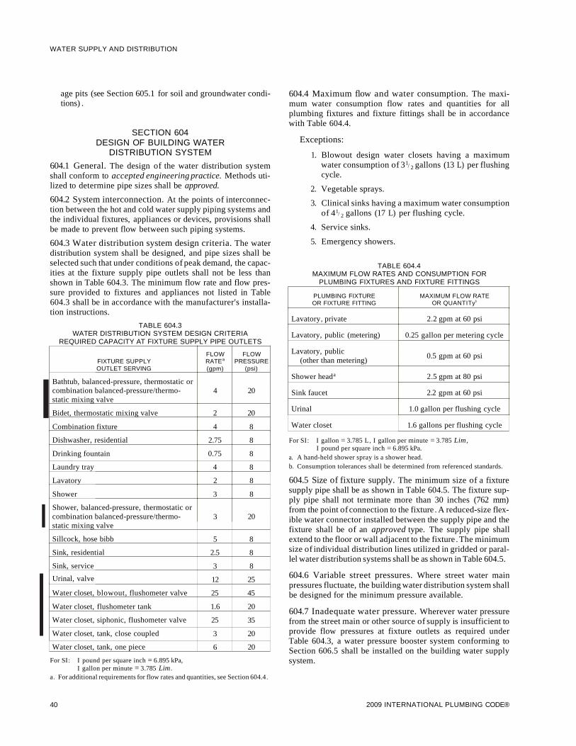
I
I
WATER SUPPLY AND DISTRIBUTION
age pits (see Section 605.1 for soil and groundwater conditions) .
SECTION 604DESIGN OF BUILDING WATER
DISTRIBUTION SYSTEM
604.1 General. The design of the water distribution systemshall conform to accepted engineering practice. Methods utilized to determine pipe sizes shall be approved.
604.2 System interconnection. At the points of interconnection between the hot and cold water supply piping systems andthe individual fixtures, appliances or devices, provisions shallbe made to prevent flow between such piping systems.
604.3 Water distribution system design criteria. The waterdistribution system shall be designed, and pipe sizes shall beselected such that under conditions of peak demand, the capacities at the fixture supply pipe outlets shall not be less thanshown in Table 604.3. The minimum flow rate and flow pressure provided to fixtures and appliances not listed in Table604.3 shall be in accordance with the manufacturer's installation instructions.
TABLE 604.3WATER DISTRIBUTION SYSTEM DESIGN CRITERIA
REQUIRED CAPACITY AT FIXTURE SUPPLY PIPE OUTLETS
FLOW FLOWFIXTURE SUPPLY RATEa PRESSUREOUTLET SERVING (gpm) (psi)
Bathtub, balanced-pressure, thermostatic orcombination balanced-pressure/thermo- 4 20static mixing valve
Bidet, thermostatic mixing valve 2 20
Combination fixture 4 8
Dishwasher, residential 2.75 8
Drinking fountain 0.75 8
Laundry tray 4 8
Lavatory 2 8
Shower 3 8
Shower, balanced-pressure, thermostatic orcombination balanced-pressure/thermo- 3 20static mixing valve
Sillcock, hose bibb 5 8
Sink, residential 2.5 8
Sink, service 3 8
Urinal, valve 12 25
Water closet, blowout, flushometer valve 25 45
Water closet, flushometer tank 1.6 20
Water closet, siphonic, flushometer valve 25 35
Water closet, tank, close coupled 3 20
Water closet, tank, one piece 6 20
For SI: I pound per square inch = 6.895 kPa,I gallon per minute = 3.785 Lim.
a. For additional requirements for flow rates and quantities, see Section 604.4.
40
604.4 Maximum flow and water consumption. The maximum water consumption flow rates and quantities for allplumbing fixtures and fixture fittings shall be in accordancewith Table 604.4.
Exceptions:
1. Blowout design water closets having a maximumwater consumption of 31/ 2 gallons (13 L) per flushingcycle.
2. Vegetable sprays.
3. Clinical sinks having a maximum water consumptionof 41/ 2 gallons (17 L) per flushing cycle.
4. Service sinks.
5. Emergency showers.
TABLE 604.4MAXIMUM FLOW RATES AND CONSUMPTION FOR
PLUMBING FIXTURES AND FIXTURE FITTINGS
PLUMBING FIXTURE MAXIMUM FLOW RATEOR FIXTURE FITTING OR QUANTITyb
Lavatory, private 2.2 gpm at 60 psi
Lavatory, public (metering) 0.25 gallon per metering cycle
Lavatory, public0.5 gpm at 60 psi
(other than metering)
Shower heada 2.5 gpm at 80 psi
Sink faucet 2.2 gpm at 60 psi
Urinal 1.0 gallon per flushing cycle
Water closet 1.6 gallons per flushing cycle
For SI: I gallon = 3.785 L, I gallon per minute = 3.785 Lim,I pound per square inch = 6.895 kPa.
a. A hand-held shower spray is a shower head.b. Consumption tolerances shall be determined from referenced standards.
604.5 Size of fixture supply. The minimum size of a fixturesupply pipe shall be as shown in Table 604.5. The fixture supply pipe shall not terminate more than 30 inches (762 mm)from the point ofconnection to the fixture . A reduced-size flexible water connector installed between the supply pipe and thefixture shall be of an approved type. The supply pipe shallextend to the floor or wall adjacent to the fixture . The minimumsize of individual distribution lines utilized in gridded or parallel water distribution systems shall be as shown in Table 604.5.
604.6 Variable street pressures. Where street water mainpressures fluctuate, the building water distribution system shallbe designed for the minimum pressure available.
604.7 Inadequate water pressure. Wherever water pressurefrom the street main or other source of supply is insufficient toprovide flow pressures at fixture outlets as required underTable 604.3, a water pressure booster system conforming toSection 606.5 shall be installed on the building water supplysystem.
2009 INTERNATIONAL PLUMBING CODE®

TABLE 604.5MINIMUM SIZES OF FIXTURE WATER SUPPLY PIPES
MINIMUM PIPE SIZEFIXTURE (inch)
Bathtubsa (60" x 32" and smaller) 1/2
Bathtubsa (larger than 60" x 32") 1/2
Bidet 3/8
Combination sink and tray 1/2
Dishwasher, domestica 1/2
Drinking fountain 3/8
Hose bibbs 1/2
Kitchen sinka 1/2
Laundry, 1, 2 or 3 compartmentsa 1/2
Lavatory 3/8
Shower, single heada 1/2
Sinks, flushing rim 3/4
Sinks, service 1/2
Urinal, flush tank 1/2
Urinal, flush valve 3/4
Wall hydrant 1/2
Water closet, flush tank 3/8
Water closet, flush valve 1
Water closet, flushometer tank 3/8
Water closet, one piecea 1/2
For 51: 1 inch = 25.4 mm, 1 foot = 304.8 mm,1 pound per square inch = 6.895 kPa.
a. Where the developed length of the distribution line is 60 feet or less, and theavailable pressure at the meter is a minimum of 35 psi, the minimum size ofan individual distribution line supplied from a manifold and installed as partof a parallel water distribution system shall be one nominal tube size smallerthan the sizes indicated.
604.8 Water-pressure reducing valve or regulator. Wherewater pressure within a building exceeds 80 psi (552 kPa)static, an approved water-pressure reducing valve conformingto ASSE 1003 with strainer shall be installed to reduce the pressure in the building water distribution piping to 80 psi (552kPa) static or less.
Exception: Service lines to sill cocks and outside hydrants,and main supply risers where pressure from the mains isreduced to 80 psi (552 kPa) or less at individual fixtures.
604.8.1 Valve design. The pressure-reducing valve shall bedesigned to remain open to permit uninterrupted water flowin case of valve failure.
604.8.2 Repair and removal. All water-pressure reducingvalves, regulators and strainers shall be so constructed andinstalled as to permit repair or removal of parts withoutbreaking a pipeline or removing the valve and strainer fromthe pipeline.
604.9 Water hammer. The flow velocity of the water distribution system shall be controlled to reduce the possibility of
2009 INTERNATIONAL PLUMBING CODE®
WATER SUPPLY AND DISTRIBUTION
water hammer. A water-hammer arrestor shall be installedwhere quick-closing valves are utilized. Water-hammerarrestors shall be installed in accordance with the manufacturer's specifications. Water-hammer arrestors shall conformto ASSE 1010.
604.10 Gridded and parallel water distribution systemmanifolds. Hot water and cold water manifolds installed withgridded or parallel connected individual distribution lines toeach fixture or fixture fitting shall be designed in accordancewith Sections 604.10.1 through 604.10.3.
604.10.1 Manifold sizing. Hot water and cold water manifolds shall be sized in accordance with Table 604.10.1. Thetotal gallons per minute is the demand of all outlets supplied.
TABLE 604.10.1MANIFOLD SIZING
NOMINAL SIZEMAXIMUM DEMAND (gpm)
INTERNAL DIAMETER Velocity at 4 feet Velocity at 8 feet(inches) per second per second
1/2 2 5
3/4 6 11
1 10 20
11/ 4 15 31
11/ 2 22 44
For 51: 1 inch = 25.4 mm, 1 gallon per minute = 3.785 Lim,1 foot per second = 0.305 m/s.
604.10.2 Valves. Individual fixture shutoff valves installedat the manifold shall be identified as to the fixture being supplied.
604.10.3 Access. Access shall be provided to manifolds Iwith integral factory- or field-installed valves.
604.11 Individual pressure balancing in-line valves forindividual fixture fittings. Where individual pressure balancing in-line valves for individual fixture fittings are installed,such valves shall comply with ASSE 1066. Such valves shall beinstalled in an accessible location and shall not be utilizedalone as a substitute for the balanced pressure, thermostatic orcombination shower valves required in Section 424.3.
SECTION 605MATERIALS, JOINTS AND CONNECTIONS
605.1 Soil and ground water. The installation of a water service or water distribution pipe shall be prohibited in soil andground water contaminated with solvents, fuels, organic compounds or other detrimental materials causing permeation, corrosion, degradation or structural failure of the piping material.Where detrimental conditions are suspected, a chemical analysis of the soil and ground water conditions shall be required toascertain the acceptability of the water service or water distribution piping material for the specific installation. Where detrimental conditions exist, approved alternative materials orrouting shall be required.
605.2 Lead content of water supply pipe and fittings. Pipeand pipe fittings, including valves and faucets, utilized in the
41

WATER SUPPLY AND DISTRIBUTION
water supply system shall have a maximum of 8-percent leadcontent.
605.3 Water service pipe. Water service pipe shall conform toNSF 61 and shall conform to one of the standards listed inTable 605.3. All water service pipe or tubing, installed underground and outside of the structure, shall have a minimumworking pressure rating of 160 psi (1100 kPa) at 73.4°F (23°C).Where the water pressure exceeds 160 psi (1100 kPa), pipingmaterial shall have a minimum rated working pressure equal tothe highest available pressure. Water service piping materialsnot third-party certified for water distribution shall terminate ator before the full open valve located at the entrance to the structure. All ductile iron water service piping shall be cement mortar lined in accordance with AWWA C104.
605.3.1 Dual check-valve-type backflow preventer.Where a dual check-valve backflow preventer is installed onthe water supply system, it shall comply with ASSE 1024 orCSA B64.6.
605.4 Water distribution pipe. Water distribution pipe shallconform to NSF 61 and shall conform to one of the standardslisted in Table 605.4. All hot water distribution pipe and tubingshall have a minimum pressure rating of 100 psi (690 kPa) at180°F (82°C).
I605.5 Fittings. Pipe fittings shall be approved for installationwith the piping material installed and shall comply with theapplicable standards listed in Table 605.5. All pipe fittings uti-
lized in water supply systems shall also comply with NSF 61. IDuctile and gray iron pipe fittings shall be cement mortar linedin accordance with AWWA C104.
605.5.1 Mechanically formed tee fittings. Mechanicallyextracted outlets shall have a height not less than three timesthe thickness of the branch tube wall.
605.5.1.1 Full flow assurance. Branch tubes shall notrestrict the flow in the run tube. A dimple/depth stop shallbe formed in the branch tube to ensure that penetrationinto the collar is of the correct depth. For inspection purposes, a second dimple shall be placed 1/4 inch (6.4 mm)above the first dimple. Dimples shall be aligned with thetube run.
605.5.1.2 Brazed joints. Mechanically formed tee fittings shall be brazed in accordance with Section605.14.1.
605.6 Flexible water connectors. Flexible water connectorsexposed to continuous pressure shall conform to ASMEAl12.18.6. Access shall be provided to all flexible water connectors.
605.7 Valves. All valves shall be of an approved type and compatible with the type of piping material installed in the system.Ball valves, gate valves, globe valves and plug valves intendedto supply drinking water shall meet the requirements of NSF61.
TABLE 605.3WATER SERVICE PIPE
I
•I
MATERIAL STANDARD
Acrylonitrile butadiene styrene (ABS) plastic pipe ASTM D 1527; ASTM D 2282
Asbestos-cement pipe ASTM C 296
Brass pipe ASTM B 43
Chlorinated polyvinyl chloride (CPVC) plastic pipe ASTM D 2846; ASTM F 441; ASTM F 442; CSA B137.6
Copper or copper-alloy pipe ASTM B 42; ASTM B 302
Copper or copper-alloy tubing (Type K, WK, L, WL, M or WM) ASTM B 75; ASTM B 88; ASTM B 251; ASTM B 447
Cross-linked polyethylene (PEX) plastic tubing ASTM F 876; ASTM F 877; CSA B137.5
Cross-linked polyethylene/aluminum/cross-linked polyethylene ASTM F 1281; ASTM F 2262; CAN/CSA B137.10M(PEX-AL-PEX) pipe
Cross-linked polyethylene/aluminum/high-density polyethyleneASTM F 1986
(PEX-AL-HDPE)
Ductile iron water pipe AWWA C151; AWWA Cl15
Galvanized steel pipe ASTMA 53
Polyethylene (PE) plastic pipe ASTM D 2239; ASTM D 3035; CSA B137.1
Polyethylene (PE) plastic tubing ASTM D 2737; CSA B137.1
Polyethylene/aluminum/polethylene (PE-AL-PE) pipe ASTM F 1282; CAN/CSA B137.9
Polypropylene (PP) plastic pipe or tubing ASTM F 2389; CSA B137.11
Polyvinyl chloride (PVC) plastic pipe ASTM D 1785; ASTM D 2241; ASTM D 2672; CSA B137.3
Stainless steel pipe (Type 304/304L) ASTM A 312; ASTM A 778
Stainless steel pipe (Type 316/316L) ASTM A 312; ASTM A 778
42 2009 INTERNATIONAL PLUMBING CODE®
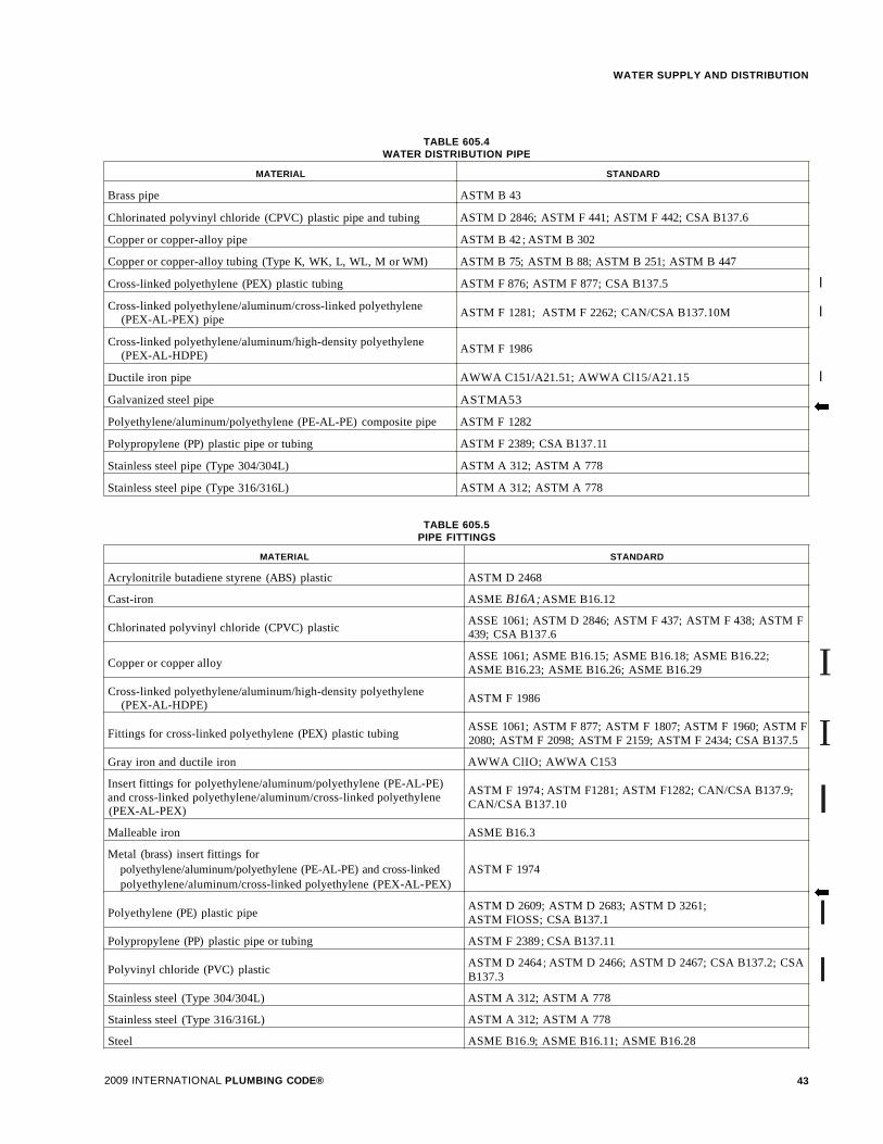
TABLE 605.4WATER DISTRIBUTION PIPE
WATER SUPPLY AND DISTRIBUTION
MATERIAL STANDARD
Brass pipe ASTM B 43
Chlorinated polyvinyl chloride (CPVC) plastic pipe and tubing ASTM D 2846; ASTM F 441; ASTM F 442; CSA B137.6
Copper or copper-alloy pipe ASTM B 42; ASTM B 302
Copper or copper-alloy tubing (Type K, WK, L, WL, M or WM) ASTM B 75; ASTM B 88; ASTM B 251; ASTM B 447
Cross-linked polyethylene (PEX) plastic tubing ASTM F 876; ASTM F 877; CSA B137.5
Cross-linked polyethylene/aluminum/cross-linked polyethyleneASTM F 1281; ASTM F 2262; CAN/CSA B137.10M
(PEX-AL-PEX) pipe
Cross-linked polyethylene/aluminum/high-density polyethyleneASTM F 1986
(PEX-AL-HDPE)
Ductile iron pipe AWWA C151/A21.51; AWWA Cl15/A21.15
Galvanized steel pipe ASTMA53
Polyethylene/aluminum/polyethylene (PE-AL-PE) composite pipe ASTM F 1282
Polypropylene (PP) plastic pipe or tubing ASTM F 2389; CSA B137.11
Stainless steel pipe (Type 304/304L) ASTM A 312; ASTM A 778
Stainless steel pipe (Type 316/316L) ASTM A 312; ASTM A 778
TABLE 605.5PIPE FITTINGS
MATERIAL STANDARD
Acrylonitrile butadiene styrene (ABS) plastic ASTM D 2468
Cast-iron ASME B16A;ASME B16.12
Chlorinated polyvinyl chloride (CPVC) plasticASSE 1061; ASTM D 2846; ASTM F 437; ASTM F 438; ASTM F439; CSA B137.6
Copper or copper alloyASSE 1061; ASME B16.15; ASME B16.18; ASME B16.22;ASME B16.23; ASME B16.26; ASME B16.29
Cross-linked polyethylene/aluminum/high-density polyethyleneASTM F 1986
(PEX-AL-HDPE)
Fittings for cross-linked polyethylene (PEX) plastic tubingASSE 1061; ASTM F 877; ASTM F 1807; ASTM F 1960; ASTM F2080; ASTM F 2098; ASTM F 2159; ASTM F 2434; CSA B137.5
Gray iron and ductile iron AWWA ClIO; AWWA C153
Insert fittings for polyethylene/aluminum/polyethylene (PE-AL-PE)ASTM F 1974; ASTM F1281; ASTM F1282; CAN/CSA B137.9;
and cross-linked polyethylene/aluminum/cross-linked polyethyleneCAN/CSA B137.10(PEX-AL-PEX)
Malleable iron ASME B16.3
Metal (brass) insert fittings forpolyethylene/aluminum/polyethylene (PE-AL-PE) and cross-linked ASTM F 1974polyethylene/aluminum/cross-linked polyethylene (PEX-AL-PEX)
Polyethylene (PE) plastic pipeASTM D 2609; ASTM D 2683; ASTM D 3261;ASTM FlOSS; CSA B137.1
Polypropylene (PP) plastic pipe or tubing ASTM F 2389; CSA B137.11
Polyvinyl chloride (PVC) plasticASTM D 2464; ASTM D 2466; ASTM D 2467; CSA B137.2; CSAB137.3
Stainless steel (Type 304/304L) ASTM A 312; ASTM A 778
Stainless steel (Type 316/316L) ASTM A 312; ASTM A 778
Steel ASME B16.9; ASME B16.11; ASME B16.28
I
I
I
•
I
I
I
•I
I
2009 INTERNATIONAL PLUMBING CODE® 43
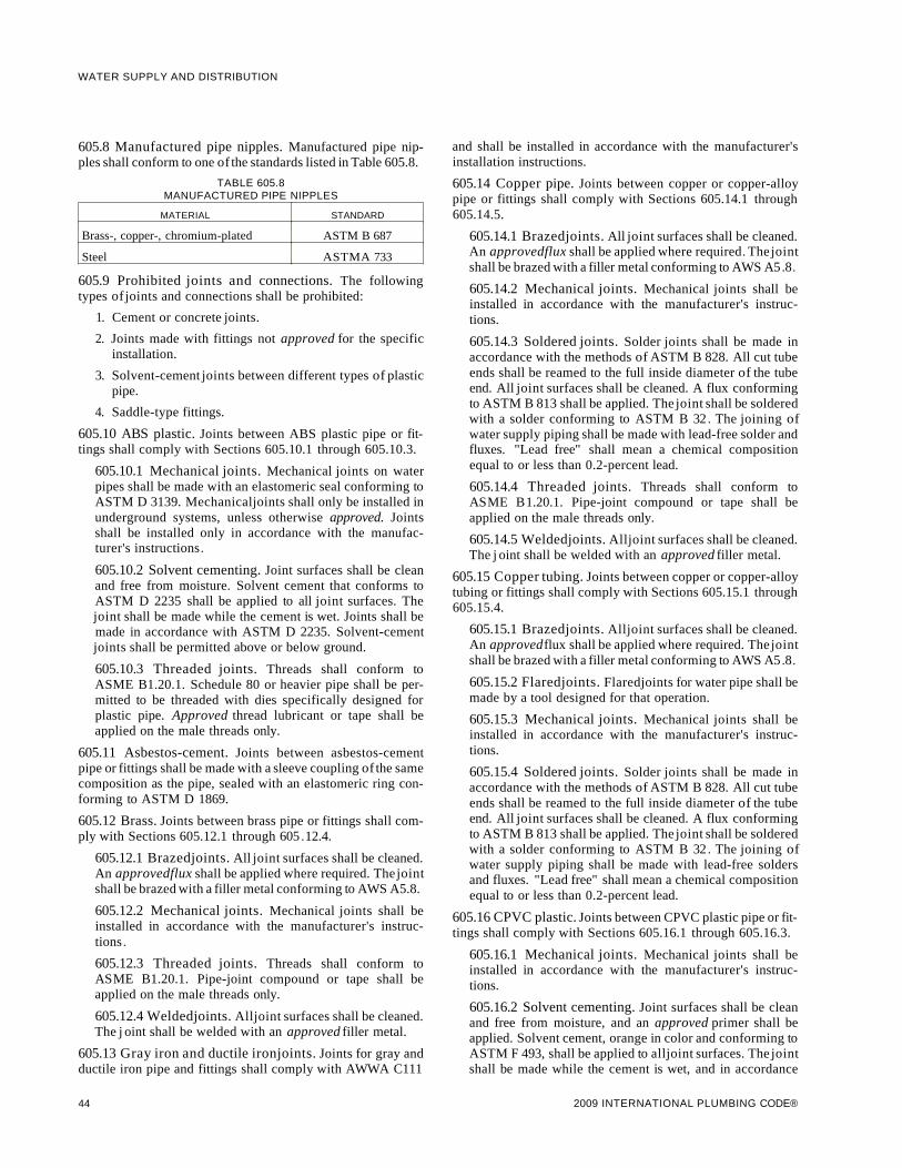
WATER SUPPLY AND DISTRIBUTION
605.8 Manufactured pipe nipples. Manufactured pipe nipples shall conform to one of the standards listed in Table 605.8.
TABLE 605.8MANUFACTURED PIPE NIPPLES
MATERIAL STANDARD
Brass-, copper-, chromium-plated ASTM B 687
Steel ASTMA 733
605.9 Prohibited joints and connections. The followingtypes of joints and connections shall be prohibited:
1. Cement or concrete joints.
2. Joints made with fittings not approved for the specificinstallation.
3. Solvent-cement joints between different types of plasticpipe.
4. Saddle-type fittings.
605.10 ABS plastic. Joints between ABS plastic pipe or fittings shall comply with Sections 605.10.1 through 605.10.3.
605.10.1 Mechanical joints. Mechanical joints on waterpipes shall be made with an elastomeric seal conforming toASTM D 3139. Mechanicaljoints shall only be installed inunderground systems, unless otherwise approved. Jointsshall be installed only in accordance with the manufacturer's instructions.
605.10.2 Solvent cementing. Joint surfaces shall be cleanand free from moisture. Solvent cement that conforms toASTM D 2235 shall be applied to all joint surfaces. Thejoint shall be made while the cement is wet. Joints shall bemade in accordance with ASTM D 2235. Solvent-cementjoints shall be permitted above or below ground.
605.10.3 Threaded joints. Threads shall conform toASME B1.20.1. Schedule 80 or heavier pipe shall be permitted to be threaded with dies specifically designed forplastic pipe. Approved thread lubricant or tape shall beapplied on the male threads only.
605.11 Asbestos-cement. Joints between asbestos-cementpipe or fittings shall be made with a sleeve coupling of the samecomposition as the pipe, sealed with an elastomeric ring conforming to ASTM D 1869.
605.12 Brass. Joints between brass pipe or fittings shall comply with Sections 605.12.1 through 605.12.4.
605.12.1 Brazedjoints. All joint surfaces shall be cleaned.An approvedflux shall be applied where required. Thejointshall be brazed with a filler metal conforming to AWS A5.8.
605.12.2 Mechanical joints. Mechanical joints shall beinstalled in accordance with the manufacturer's instructions.
605.12.3 Threaded joints. Threads shall conform toASME B1.20.1. Pipe-joint compound or tape shall beapplied on the male threads only.
605.12.4 Weldedjoints. Alljoint surfaces shall be cleaned.The j oint shall be welded with an approved filler metal.
605.13 Gray iron and ductile ironjoints. Joints for gray andductile iron pipe and fittings shall comply with AWWA C111
44
and shall be installed in accordance with the manufacturer'sinstallation instructions.
605.14 Copper pipe. Joints between copper or copper-alloypipe or fittings shall comply with Sections 605.14.1 through605.14.5.
605.14.1 Brazedjoints. All joint surfaces shall be cleaned.An approvedflux shall be applied where required. Thejointshall be brazed with a filler metal conforming to AWS A5.8.
605.14.2 Mechanical joints. Mechanical joints shall beinstalled in accordance with the manufacturer's instructions.
605.14.3 Soldered joints. Solder joints shall be made inaccordance with the methods of ASTM B 828. All cut tubeends shall be reamed to the full inside diameter of the tubeend. All joint surfaces shall be cleaned. A flux conformingto ASTM B 813 shall be applied. The joint shall be solderedwith a solder conforming to ASTM B 32. The joining ofwater supply piping shall be made with lead-free solder andfluxes. "Lead free" shall mean a chemical compositionequal to or less than 0.2-percent lead.
605.14.4 Threaded joints. Threads shall conform toASME B1.20.1. Pipe-joint compound or tape shall beapplied on the male threads only.
605.14.5 Weldedjoints. Alljoint surfaces shall be cleaned.The j oint shall be welded with an approved filler metal.
605.15 Copper tubing. Joints between copper or copper-alloytubing or fittings shall comply with Sections 605.15.1 through605.15.4.
605.15.1 Brazedjoints. Alljoint surfaces shall be cleaned.An approvedflux shall be applied where required. Thejointshall be brazed with a filler metal conforming to AWS A5.8.
605.15.2 Flaredjoints. Flaredjoints for water pipe shall bemade by a tool designed for that operation.
605.15.3 Mechanical joints. Mechanical joints shall beinstalled in accordance with the manufacturer's instructions.
605.15.4 Soldered joints. Solder joints shall be made inaccordance with the methods of ASTM B 828. All cut tubeends shall be reamed to the full inside diameter of the tubeend. All joint surfaces shall be cleaned. A flux conformingto ASTM B 813 shall be applied. The joint shall be solderedwith a solder conforming to ASTM B 32. The joining ofwater supply piping shall be made with lead-free soldersand fluxes. "Lead free" shall mean a chemical compositionequal to or less than 0.2-percent lead.
605.16 CPVC plastic. Joints between CPVC plastic pipe or fittings shall comply with Sections 605.16.1 through 605.16.3.
605.16.1 Mechanical joints. Mechanical joints shall beinstalled in accordance with the manufacturer's instructions.
605.16.2 Solvent cementing. Joint surfaces shall be cleanand free from moisture, and an approved primer shall beapplied. Solvent cement, orange in color and conforming toASTM F 493, shall be applied to alljoint surfaces. The jointshall be made while the cement is wet, and in accordance
2009 INTERNATIONAL PLUMBING CODE®

with ASTM D 2846 or ASTM F 493. Solvent-cementjointsshall be permitted above or below ground.
Exception: A primer is not required where all of the following conditions apply:
1. The solvent cement used is third-party certified asconforming to ASTM F 493.
2. The solvent cement used is yellow in color.
3. The solvent cement is used only for joining 1/2 inch(12.7 mm) through 2 inch (51 mm) diameterCPVC pipe and fittings.
4. The CPVC pipe and fittings are manufactured inaccordance with ASTM D 2846.
605.16.3 Threaded joints. Threads shall conform toASME B1.20.1. Schedule 80 or heavier pipe shall be permitted to be threaded with dies specifically designed forplastic pipe, but the pressure rating of the pipe shall bereduced by 50 percent. Thread by socket molded fittingsshall be permitted. Approved thread lubricant or tape shallbe applied on the male threads only.
605.17 Cross-linked polyethylene plastic. Joints betweencross-linked polyethylene plastic tubing or fittings shall comply with Sections 605.17.1 and 605.17.2.
605.17.1 Flaredjoints. Flared pipe ends shall be made by atool designed for that operation.
605.17.2 Mechanical joints. Mechanical joints shall beinstalled in accordance with the manufacturer 's instructions. Fittings for cross-linked polyethylene (PEX) plastictubing shall comply with the applicable standards listed inTable 605.5 and shall be installed in accordance with themanufacturer's instructions. PEX tubing shall be factorymarked with the appropriate standards for the fittings thatthe PEX manufacturer specifies for use with the tubing.
605.18 Steel. Joints between galvanized steel pipe or fittingsshall comply with Sections 605.18.1 and 605.18.2.
605.18.1 Threaded joints. Threads shall conform toASME B1.20.1. Pipe-joint compound or tape shall beapplied on the male threads only.
605.18.2 Mechanicaljoints. Joints shall be made with anapproved elastomeric seal. Mechanical joints shall beinstalled in accordance with the manufacturer 's instructions.• 605.19 Polyethylene plastic. Joints between polyethylene
plastic pipe and tubing or fittings shall comply with Sections605.19.1 through 605.19.4.
605.19.1 Flared joints. Flared joints shall be permittedwhere so indicated by the pipe manufacturer. Flared jointsshall be made by a tool designed for that operation.
605.19.2 Heat-fusion joints. Joint surfaces shall be cleanand free from moisture. Alljoint surfaces shall be heated tomelt temperature andjoined. Thejoint shall be undisturbeduntil cool. Joints shall be made in accordance with ASTM D2657.
2009 INTERNATIONAL PLUMBING CODE®
WATER SUPPLY AND DISTRIBUTION
605.19.3 Mechanical joints. Mechanical joints shall beinstalled in accordance with the manufacturer's instructions.
605.19.4 Installation. Polyethylene pipe shall be cutsquare, with a cutter designed for plastic pipe. Except wherejoined by heat fusion, pipe ends shall be chamfered toremove sharp edges. Kinked pipe shall not be installed. Theminimum pipe bending radius shall not be less than 30 pipediameters, or the minimum coil radius, whichever is greater.Piping shall not be bent beyond straightening of the curvature of the coil. Bends shall not be permitted within 10 pipediameters of any fitting or valve. Stiffener inserts installedwith compression-type couplings and fittings shall notextend beyond the clamp or nut of the coupling or fitting.
605.20 Polypropylene (PP) plastic. Joints between PP plasticpipe and fittings shall comply with Section 605.20.1 or605.20.2.
605.20.1 Heat-fusion joints. Heat-fusion joints for polypropylene pipe and tubing joints shall be installed withsocket-type heat-fused polypropylene fittings, butt-fusionpolypropylene fittings or electrofusion polypropylene fittings. Joint surfaces shall be clean and free from moisture.The joint shall be undisturbed until cool. Joints shall bemade in accordance with ASTM F 2389.
605.20.2 Mechanical and compression sleeve joints.Mechanical and compression sleeve joints shall be installedin accordance with the manufacturer's instructions.
605.21 Polyethylene/aluminum/polyethylene (PE-AL-PE)and cross-linked polyethylene/aluminum/cross-linkedpolyethylene (PEX-AL-PEX). Joints between PE-AL-PE andPEX-AL-PEX pipe and fittings shall comply with Section605.21.1.
605.21.1 Mechanical joints. Mechanical joints shall beinstalled in accordance with the manufacturer's instructions. Fittings for PE-AL-PE and PEX-AL-PEX asdescribed in ASTM F 1974, ASTM F 1281, ASTM F 1282,CAN/CSA B137.9 and CAN/CSA B137.10 shall beinstalled in accordance with the manufacturer's instructions.
605.22 PVC plastic. Joints between PVC plastic pipe or fittings shall comply with Sections 605.22.1 through 605.22.3.
605.22.1 Mechanical joints. Mechanical joints on waterpipe shall be made with an elastomeric seal conforming toASTM D 3139. Mechanical joints shall not be installed inabove-ground systems unless otherwise approved. Jointsshall be installed in accordance with the manufacturer 'sinstructions.
605.22.2 Solvent cementing. Joint surfaces shall be cleanand free from moisture. A purple primer that conforms toASTM F 656 shall be applied. Solvent cement not purple incolor and conforming to ASTM D 2564 or CSA-B137.3shall be applied to alljoint surfaces. The joint shall be madewhile the cement is wet and shall be in accordance with
45

WATER SUPPLY AND DISTRIBUTION
ASTM D 2855. Solvent-cement joints shall be permittedabove or below ground.
605.22.3 Threaded joints. Threads shall conform toASME B1.20.1. Schedule 80 or heavier pipe shall be permitted to be threaded with dies specifically designed forplastic pipe, but the pressure rating of the pipe shall bereduced by 50 percent. Thread by socket molded fittingsshall be permitted. Approved thread lubricant or tape shallbe applied on the male threads only.
605.23 Stainless steel. Joints between stainless steel pipe andfittings shall comply with Sections 605.23.1 and 605.23.2.
605.23.1 Mechanical joints. Mechanical joints shall beinstalled in accordance with the manufacturer's instructions.
605.23.2 Weldedjoints. Alljoint surfaces shall be cleaned.The joint shall be welded autogenously or with an approvedfiller metal as referenced in ASTM A 312.
605.24 Joints between different materials. Joints betweendifferent piping materials shall be made with a mechanicaljoint of the compression or mechanical-sealing type, or as permitted in Sections 605.24.1, 605.24.2 and 605.24.3. Connectors or adapters shall have an elastomeric seal conforming toASTM D 1869 or ASTM F 477. Joints shall be installed inaccordance with the manufacturer's instructions.
605.24.1 Copper or copper-alloy tubing to galvanizedsteel pipe. Joints between copper or copper-alloy tubingand galvanized steel pipe shall be made with a brass fittingor dielectric fitting or a dielectric union conforming toASSE 1079. The copper tubing shall be soldered to the fitting in an approved manner, and the fitting shall be screwedto the threaded pipe.
605.24.2 Plastic pipe or tubing to other piping material.Joints between different grades of plastic pipe or betweenplastic pipe and other piping material shall be made with anapproved adapter fitting.
605.24.3 Stainless steel. Joints between stainless steel anddifferent piping materials shall be made with a mechanicaljoint of the compression or mechanical sealing type or adielectric fitting or a dielectric union conforming to ASSE1079.
SECTION 606INSTALLATION OF THE BUILDING
WATER DISTRIBUTION SYSTEM
606.1 Location of full-open valves. Full-open valves shall beinstalled in the following locations:
1. On the building water service pipe from the public watersupply near the curb.
2. On the water distribution supply pipe at the entrance intothe structure.
3. On the discharge side of every water meter.
4. On the base of every water riser pipe in occupanciesother than multiple-family residential occupancies that
46
are two stories or less in height and in one- and two-family residential occupancies.
5. On the top of every water down-feed pipe in occupanciesother than one- and two-family residential occupancies.
6. On the entrance to every water supply pipe to a dwellingunit, except where supplying a single fixture equippedwith individual stops.
7. On the water supply pipe to a gravity or pressurizedwater tank.
8. On the water supply pipe to every water heater.
606.2 Location of shutoff valves. Shutoff valves shall beinstalled in the following locations:
1. On the fixture supply to each plumbing fixture other thanbathtubs and showers in one- and two-family residentialoccupancies, and other than in individual sleeping unitsthat are provided with unit shutoff valves in hotels,motels, boarding houses and similar occupancies.
2. On the water supply pipe to each sillcock.
3. On the water supply pipe to each appliance or mechani-cal equipment.
606.3 Access to valves. Access shall be provided to allfull-open valves and shutoff valves.
606.4 Valve identification. Service and hose bibb valves shallbe identified. All other valves installed in locations that are notadjacent to the fixture or appliance shall be identified, indicating the fixture or appliance served.
606.5 Water pressure booster systems. Water pressurebooster systems shall be provided as required by Sections606.5.1 through 606.5.10.
606.5.1 Water pressure booster systems required. Wherethe water pressure in the public water main or individualwater supply system is insufficient to supply the minimumpressures and quantities specified in this code, the supplyshall be supplemented by an elevated water tank, ahydropneumatic pressure booster system or a water pressure booster pump installed in accordance with Section606.5.5.
606.5.2 Support. All water supply tanks shall be supportedin accordance with the International Building Code.
606.5.3 Covers. All water supply tanks shall be covered tokeep out unauthorized persons, dirt and vermin. The coversof gravity tanks shall be vented with a return bend vent pipewith an area not less than the area of the down-feed riserpipe, and the vent shall be screened with a corrosion-resistant screen of not less than 16 by 20 mesh per inch (630 by787 mesh per m).
606.5.4 Overflows for water supply tanks. Each gravity orsuction water supply tank shall be provided with an overflow with a diameter not less than that shown in Table606.5.4. The overflow outlet shall discharge at a point notless than 6 inches (152 mm) above the roof or roof drain;floor or floor drain; or over an open water-supplied fixture.The overflow outlet shall be covered with a corrosion-resis-
2009 INTERNATIONAL PLUMBING CODE®

tant screen of not less than 16 by 20 mesh per inch (630 by787 mesh per m) and by 1/4-inch (6.4 mm) hardware cloth orshall terminate in a horizontal angle seat check valve. Drainage from overflow pipes shall be directed so as not to freezeon roof walks.
TABLE 606.5.4SIZES FOR OVERFLOW PIPES FOR WATER SUPPLY TANKS
MAXIMUM CAPACITY OF WATER DIAMETER OF OVERFLOW PIPESUPPLY LINE TO TANK (gpm) (inches)
0-50 2
50 - 150 21/ 2
150 - 200 3
200 - 400 4
400 - 700 5
700 - 1,000 6
Over 1,000 8
For SI: 1 inch = 25.4 mm, 1 gallon per minute = 3.785 Lim.
606.5.5 Low-pressure cutoffrequired on booster pumps.A low-pressure cutoff shall be installed on all boosterpumps in a water pressure booster system to prevent creation of a vacuum or negative pressure on the suction side ofthe pump when a positive pressure of 10 psi (68.94 kPa) orless occurs on the suction side of the pump.
606.5.6 Potable water inlet control and location. Potablewater inlets to gravity tanks shall be controlled by a fill valveor other automatic supply valve installed so as to prevent thetank from overflowing. The inlet shall be terminated so as toprovide an airgap not less than 4 inches (102 mm) above theoverflow.
606.5.7 Tank drain pipes. A valved pipe shall be providedat the lowest point of each tank to permit emptying of thetank. The tank drain pipe shall discharge as required foroverflow pipes and shall not be smaller in size than specifiedin Table 606.5.7.
TABLE 606.5.7SIZE OF DRAIN PIPES FOR WATER TANKS
TANK CAPACITY (gallons) DRAIN PIPE (inches)
Up to 750 1
751 to 1,500 11/ 2
1,501 to 3,000 2
3,001 to 5,000 21/ 2
5,000 to 7,500 3
Over 7,500 4
For SI: 1 inch = 25.4 mm, 1 gallon = 3.785 L.
606.5.8 Prohibited location of potable supply tanks.Potable water gravity tanks or manholes of potable waterpressure tanks shall not be located directly under any soil orwaste piping or any source of contamination.
2009 INTERNATIONAL PLUMBING CODE®
WATER SUPPLY AND DISTRIBUTION
606.5.9 Pressure tanks, vacuum relief. All water pressuretanks shall be provided with a vacuum relief valve at the topof the tank that will operate up to a maximum water pressureof 200 psi (1380 kPa) and up to a maximum temperature of200°F (93°C). The minimum size of such vacuum reliefvalve shall be 1/2 inch (12.7 mm).
Exception: This section shall not apply to pressurizedcaptive air diaphragm/bladder tanks.
606.5.10 Pressure relieffor tanks. Every pressure tank in ahydropneumatic pressure booster system shall be protectedwith a pressure relief valve. The pressure relief valve shallbe set at a maximum pressure equal to the rating of the tank.The relief valve shall be installed on the supply pipe to thetank or on the tank. The relief valve shall discharge by gravity to a safe place of disposal.
606.6 Water supply system test. Upon completion of a section of or the entire water supply system, the system, or portioncompleted, shall be tested in accordance with Section 312.
SECTION 607HOT WATER SUPPLY SYSTEM
607.1 Where required. In residential occupancies, hot watershall be supplied to all plumbing fixtures and equipment utilized for bathing, washing, culinary purposes, cleansing, laundry or building maintenance. In nonresidential occupancies,hot water shall be supplied for culinary purposes, cleansing,laundry or building maintenance purposes. In nonresidentialoccupancies, hot wateror tempered watershall be supplied forbathing and washing purposes. Tempered water shall be supplied through a water temperature limiting device that conforms to ASSE 1070 and shall limit the tempered water to amaximum of 11O°F (43°C). This provision shall not supersedethe requirement for protective shower valves in accordancewith Section 424.3.
607.2 Hot water supply temperature maintenance. Wherethe developed length of hot water piping from the source of hotwater supply to the farthest fixture exceeds 100 feet (30 480mm), the hot water supply system shall be provided with amethod of maintaining the temperature in accordance with theInternational Energy Conservation Code.
607.2.1 Piping insulation. Circulating hot water systempiping shall be insulated in accordance with the International Energy Conservation Code.
[E] 607.2.2 Hot water system controls. Automatic circulating hot water system pumps or heat trace shall bearranged to be conveniently turned off, automatically ormanually, when the hot water system is not in operation.
607.2.3 Recirculating pump. Where a thermostatic mixingvalve is used in a system with a hot water recirculatingpump, the hot water or tempered water return line shall berouted to the cold water inlet pipe of the water heater and thecold water inlet pipe or the hot water return connection ofthe thermostatic mixing valve.
47
WATER SUPPLY AND DISTRIBUTION
607.3 Thermal expansion control. A means of controllingincreased pressure caused by thermal expansion shall be provided where required in accordance with Sections 607.3.1 and607.3.2.
607.3.1 Pressure-reducing valve. For water service systemsizes up to and including 2 inches (51 mm), a device for controlling pressure shall be installed where, because of thermal expansion, the pressure on the downstream side of apressure-reducing valve exceeds the pressure-reducingvalve setting.
607.3.2 Backflow prevention device or check valve.Where a backflow prevention device, check valve or otherdevice is installed on a water supply system utilizing storagewater heating equipment such that thermal expansioncauses an increase in pressure, a device for controlling pressure shall be installed.
607.4 Flow of hot water to fixtures. Fixture fittings, faucetsand diverters shall be installed and adjusted so that the flow ofhot water from the fittings corresponds to the left-hand side ofthe fixture fitting.
Exception: Shower and tub/shower mixing valves conforming to ASSE 1016 or ASME Al12.18.1/CSA B125.1,where the flow of hot water corresponds to the markings onthe device.
SECTION 608PROTECTION OF POTABLE WATER SUPPLY
608.1 General. A potable water supply system shall bedesigned, installed and maintained in such a manner so as toprevent contamination from nonpotable liquids, solids or gasesbeing introduced into the potable water supply throughcross-connections or any other piping connections to the system. Backflow preventer applications shall conform to Table608.1, except as specifically stated in Sections 608.2 through608.16.10.
608.2 Plumbing fixtures. The supply lines and fittings forevery plumbing fixture shall be installed so as to preventbackflow. Plumbing fixture fittings shall provide backflowprotection in accordance with ASME A112.18.1.
608.3 Devices, appurtenances, appliances and apparatus.All devices, appurtenances, appliances and apparatus intendedto serve some special function, such as sterilization, distillation, processing, cooling, or storage of ice or foods, and thatconnect to the water supply system, shall be provided with protection against backflow and contamination ofthe water supplysystem. Water pumps, filters, softeners, tanks and all otherappliances and devices that handle or treat potable water shallbe protected against contamination.
608.3.1 Special equipment, water supply protection. Thewater supply for hospital fixtures shall be protected againstbackflow with a reduced pressure principle backflowpreventer, an atmospheric or spill-proof vacuum breaker, oran airgap. Vacuum breakers for bedpan washer hoses shall
48
not be located less than 5 feet (1524 mm) above the floor.Vacuum breakers for hose connections in health care or laboratory areas shall not be less than 6 feet (1829 mm) abovethe floor.
608.4 Water service piping. Water service piping shall be protected in accordance with Sections 603.2 and 603.2.1.
608.5 Chemicals and other substances. Chemicals and othersubstances that produce either toxic conditions, taste, odor ordiscoloration in a potable water system shall not be introducedinto, or utilized in, such systems.
608.6 Cross-connection control. Cross connections shall beprohibited, except where approved protective devices areinstalled.
608.6.1 Private water supplies. Cross connectionsbetween a private water supply and a potable public supplyshall be prohibited.
608.7 Valves and outlets prohibited below grade. Potablewater outlets and combination stop-and-waste valves shall notbe installed underground or below grade. Freezeproof yardhydrants that drain the riser into the ground are considered to bestop-and-waste valves.
Exception: Freezeproof yard hydrants that drain the riserinto the ground shall be permitted to be installed, providedthat the potable water supply to such hydrants is protectedupstream of the hydrants in accordance with Section 608and the hydrants are permanently identified as nonpotableoutlets by approvedsignage that reads as follows: "Caution,Nonpotable Water. Do Not Drink."
608.8 Identification ofnonpotable water. In buildings wherenonpotable water systems are installed, the piping conveyingthe nonpotable water shall be identified either by color markingor metal tags in accordance with Sections 608.8.1 through608.8.3. All nonpotable water outlets such as hose connections, open ended pipes, and faucets shall be identified at thepoint of use for each outlet with the words, "Nonpotable-notsafe for drinking." The words shall be indelibly printed on a tagor sign constructed of corrosion-resistant waterproof materialor shall be indelibly printed on the fixture. The letters of thewords shall be not less than 0.5 inches in height and color incontrast to the background on which they are applied.
608.8.1 Information. Pipe identification shall include thecontents of the piping system and an arrow indicating thedirection of flow. Hazardous piping systems shall also contain information addressing the nature of the hazard. Pipeidentification shall be repeated at maximum intervals of 25feet (7620 mm) and at each point where the piping passesthrough a wall, floor or roof. Lettering shall be readilyobservable within the room or space where the piping islocated.
608.8.2 Color. The color of the pipe identification shall be Idiscernable and consistent throughout the building. Thecolor purple shall be used to identify reclaimed, rain andgray water distribution systems.
2009 INTERNATIONAL PLUMBING CODE®

TABLE 608.1APPLICATION OF BACKFLOW PREVENTERS
WATER SUPPLY AND DISTRIBUTION
DEVICE DEGREE OF HAZARDa APPLICATIONb APPLICABLE STANDARDS
Air gap High or low hazard Backsiphonage or backpressure ASME Al12.1.2
Air gap fittings for use with plumbingHigh or low hazard Backsiphonage or backpressure ASME Al12.1.3
fixtures, appliances and appurtenances
Antisiphon-type fill valves for gravityHigh hazard Backsiphonage only ASSE 1002, CSA B125.3
water closet flush tanks
Backflow preventer for carbonatedLow hazard
Backpressure or backsiphonageASSE 1022
beverage machines Sizes 1/4"- 3/8"
Backflow preventer with intermediateLow hazard
Backpressure or backsiphonageASSE 1012, CANICSA B64.3
atmospheric vents Sizes 1/4" - 3/4"
Barometric loop High or low hazard Backsiphonage only (See Section 608.13.4)
Double check backflow prevention Backpressure or backsiphonage ASSE 1015, AWWA C510,assembly and double check fire Low hazard Sizes 3/8" - 16" CSA B64.5, CSA B64.5.1protection backflow prevention assembly
Double check detector fire protectionBackpressure or backsiphonage
Low hazard (Fire sprinkler systems) ASSE 1048backflow prevention assemblies
Sizes 2" - 16"
Dual-check-valve-type backflow preventer Low hazardBackpressure or backsiphonage
ASSE 1024, CSA B64.6Sizes 1/4" - 1"
Low head backpressure, ratedHose connection backflow preventer High or low hazard working pressure, backpressure ASSE 1052, CSA B64.2.1.1
or backsiphonage Sizes 1/2"-1"
Low head backpressure orASSE 1011, CANICSA B64.2,
Hose connection vacuum breaker High or low hazard backsiphonageCSA B64.2.1Sizes 1/2", 3/4", 1"
Laboratory faucet backflow preventer High or low hazardLow head backpressure and
ASSE 1035, CSA B64.7backsiphonage
Pipe-applied atmospheric-type vacuumHigh or low hazard
Backsiphonage onlyASSE 1001, CANICSA B64.1.1
breaker Sizes 1/4" - 4"
Pressure vacuum breaker assembly High or low hazardBacksiphonage only
ASSE 1020, CSA B64.1.2Sizes 1/2" - 2"
Reduced pressure principle backflow Backpressure or backsiphonage ASSE 1013, AWWA C511,preventer and reduced pressure principle High or low hazard Sizes 3/ 8"- 16" CANICSA B64.4, CSA B64.4.1fire protection backflow preventer
Reduced pressure detector fire protectionHigh or low hazard
Backsiphonage or backpressureASSE 1047
backflow prevention assemblies (Fire sprinkler systems)
Spillproof vacuum breaker High or low hazardBacksiphonage only
ASSE 1056Sizes 1/4"-2"
Vacuum breaker wall hydrants,Low head backpressure or
High or low hazard backsiphonage ASSE 1019, CANICSA B64.2.2frost-resistant, automatic draining type Sizes 3/4", 1"
For SI: 1 inch = 25.4 mm.a. Low hazard-See Pollution (Section 202).
High hazard-See Contamination (Section 202).b. See Backpressure (Section 202).
See Backpressure, low head (Section 202).See Backsiphonage (Section 202).
II
2009 INTERNATIONAL PLUMBING CODE® 49

WATER SUPPLY AND DISTRIBUTION
608.8.3 Size. The size of the background color field and lettering shall comply with Table 608.8.3.
TABLE 608.8.3SIZE OF PIPE IDENTIFICATION
LENGTH BACKGROUND SIZE OFPIPE DIAMETER COLOR FIELD LETTERS
(inches) (inches) (inches)
3/4 to 11/ 4 8 0.5
11/ 2 to 2 8 0.75
21/ 2 to 6 12 1.25
8 to 10 24 2.5
over 10 32 3.5
For 51: 1 inch = 25.4 mm.
608.9 Reutilization prohibited. Water utilized for the coolingof equipment or other processes shall not be returned to thepotable water system. Such water shall be discharged into adrainage system through an airgap or shall be utilized for nonpotable purposes.
608.10 Reuse of piping. Piping that has been utilized for anypurpose other than conveying potable water shall not be utilized for conveying potable water.
608.11 Painting ofwater tanks. The interior surface ofa potable water tank shall not be lined, painted or repaired with anymaterial that changes the taste, odor, color or potability of thewater supply when the tank is placed in, or returned to, service.
608.12 Pumps and other appliances. Water pumps, filters,softeners, tanks and all other devices that handle or treat potable water shall be protected against contamination.
608.13 Backflow protection. Means of protection againstbackflow shall be provided in accordance with Sections608.13.1 through 608.13.9.
608.13.1 Air gap. The minimum required air gap shall bemeasured vertically from the lowest end of a potable wateroutlet to the flood level rim of the fixture or receptacle intowhich such potable water outlet discharges. Air gaps shallcomply with ASME Al12.1.2 and air gap fittings shallcomply with ASME Al12 .1.3.
608.13.2 Reduced pressure principle backflowpreventers. Reduced pressure principle backflowpreventers shall conform to ASSE 1013, AWWA C511,CAN/CSA B64.4 or CSA B64.4.1. Reduced pressure detector assembly backflow preventers shall conform to ASSE1047. These devices shall be permitted to be installed wheresubject to continuous pressure conditions. The relief opening shall discharge by air gap and shall be prevented frombeing submerged.
608.13.3 Backflow preventer with intermediate atmospheric vent. Backflow preventers with intermediate atmospheric vents shall conform to ASSE 1012 or CAN/CSAB64.3. These devices shall be permitted to be installedwhere subject to continuous pressure conditions. The relief
50
opening shall discharge by air gap and shall be preventedfrom being submerged.
608.13.4 Barometric loop. Barometric loops shall precedethe point of connection and shall extend vertically to aheight of 35 feet (10 668 mm). A barometric loop shall onlybe utilized as an atmospheric-type or pressure-type vacuumbreaker.
608.13.5 Pressure-type vacuum breakers. Pressure-typevacuum breakers shall conform to ASSE 1020 or CSAB64.1.2 and spillproof vacuum breakers shall comply withASSE 1056. These devices are designed for installationunder continuous pressure conditions when the critical levelis installed at the required height. Pressure-type vacuumbreakers shall not be installed in locations where spillagecould cause damage to the structure.
608.13.6 Atmospheric-type vacuum breakers. Pipeapplied atmospheric-type vacuum breakers shall conformto ASSE 1001 or CAN/CSA B64.1.1. Hose-connection vacuum breakers shall conform to ASSE 1011, ASSE 1019,ASSE 1035, ASSE 1052, CAN/CSA B64.2, CSA B64.2.1,CSA B64.2.1.1, CAN/CSA B64.2.2 or CSA B64.7. Thesedevices shall operate under normal atmospheric pressurewhen the critical level is installed at the required height.
608.13.7 Double check-valve assemblies. Double checkvalve assemblies shall conform to ASSE 1015, CSA B64.5,CSA B64.5.1 or AWWA C510. Double-detectorcheck-valve assemblies shall conform to ASSE 1048. Thesedevices shall be capable ofoperating under continuous pressure conditions.
608.13.8 Spillproofvacuum breakers. Spillproofvacuumbreakers (SVB) shall conform to ASSE 1056. These devicesare designed for installation under continuous-pressureconditions when the critical level is installed at the requiredheight.
608.13.9 Chemical dispenser backflow devices. Backflow devices for chemical dispensers shall comply withASSE 1055 or shall be equipped with an air gap fitting.
608.14 Location ofbackflow preventers. Access shall be provided to backflow preventers as specified by the installationinstructions of the approved manufacturer.
608.14.1 Outdoor enclosures for backflow preventiondevices. Outdoor enclosures for backflow preventiondevices shall comply with ASSE 1060.
608.14.2 Protection of backflow preventers. Backflowpreventers shall not be located in areas subject to freezingexcept where they can be removed by means ofunions or areprotected from freezing by heat, insulation or both.
608.14.2.1 Relief port piping. The termination of thepiping from the reliefport or airgap fitting ofa backflowpreventer shall discharge to an approved indirect wastereceptor or to the outdoors where it will not cause damage or create a nuisance.
608.15 Protection ofpotable water outlets. All potable wateropenings and outlets shall be protected against backflow inaccordance with Section 608.15.1, 608.15.2, 608.15.3,608.15.4,608.15.4.1 or 608.15.4.2.
2009 INTERNATIONAL PLUMBING CODE®
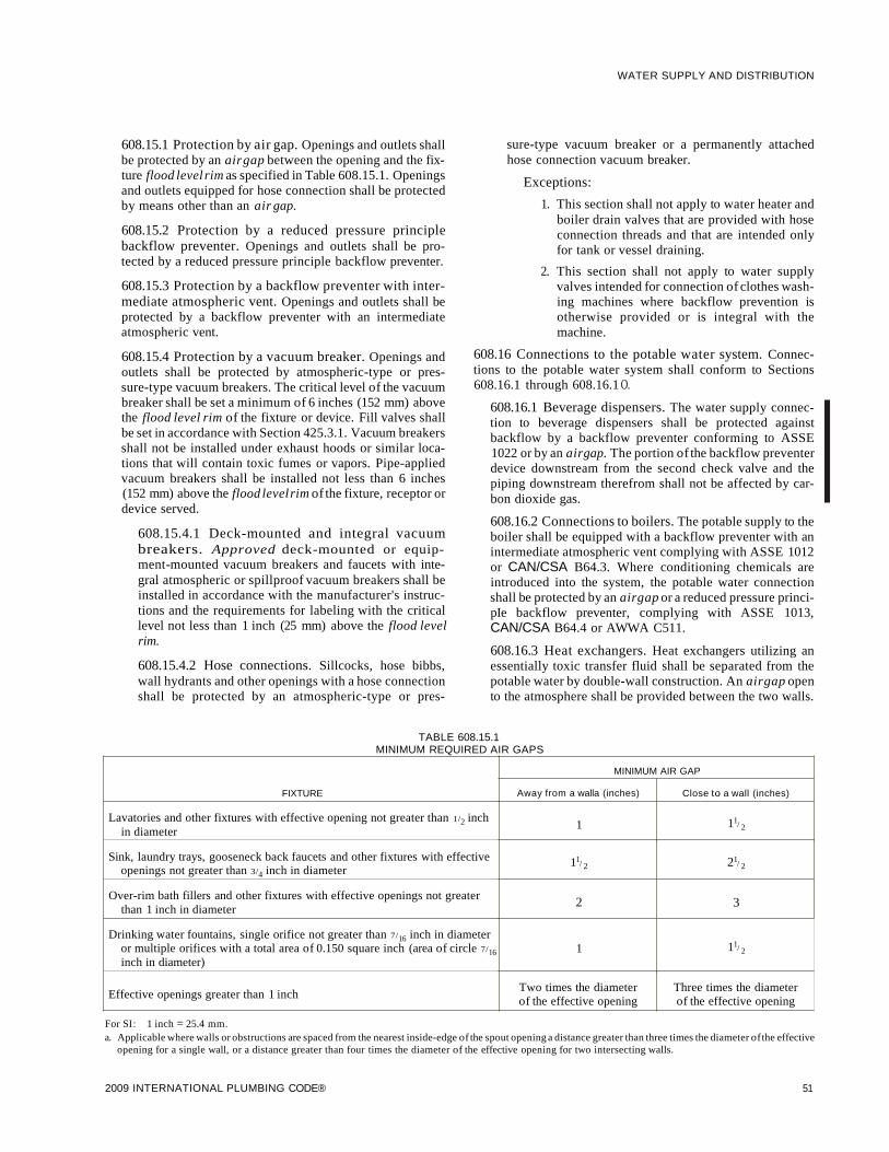
608.15.1 Protection by air gap. Openings and outlets shallbe protected by an airgap between the opening and the fixture flood level rim as specified in Table 608.15.1. Openingsand outlets equipped for hose connection shall be protectedby means other than an air gap.
608.15.2 Protection by a reduced pressure principlebackflow preventer. Openings and outlets shall be protected by a reduced pressure principle backflow preventer.
608.15.3 Protection by a backflow preventer with intermediate atmospheric vent. Openings and outlets shall beprotected by a backflow preventer with an intermediateatmospheric vent.
608.15.4 Protection by a vacuum breaker. Openings andoutlets shall be protected by atmospheric-type or pressure-type vacuum breakers. The critical level of the vacuumbreaker shall be set a minimum of 6 inches (152 mm) abovethe flood level rim of the fixture or device. Fill valves shallbe set in accordance with Section 425.3.1. Vacuum breakersshall not be installed under exhaust hoods or similar locations that will contain toxic fumes or vapors. Pipe-appliedvacuum breakers shall be installed not less than 6 inches(152 mm) above the flood levelrim of the fixture, receptor ordevice served.
608.15.4.1 Deck-mounted and integral vacuumbreakers. Approved deck-mounted or equipment-mounted vacuum breakers and faucets with integral atmospheric or spillproof vacuum breakers shall beinstalled in accordance with the manufacturer's instructions and the requirements for labeling with the criticallevel not less than 1 inch (25 mm) above the flood levelrim.
608.15.4.2 Hose connections. Sillcocks, hose bibbs,wall hydrants and other openings with a hose connectionshall be protected by an atmospheric-type or pres-
WATER SUPPLY AND DISTRIBUTION
sure-type vacuum breaker or a permanently attachedhose connection vacuum breaker.
Exceptions:
1. This section shall not apply to water heater andboiler drain valves that are provided with hoseconnection threads and that are intended onlyfor tank or vessel draining.
2. This section shall not apply to water supplyvalves intended for connection of clothes washing machines where backflow prevention isotherwise provided or is integral with themachine.
608.16 Connections to the potable water system. Connections to the potable water system shall conform to Sections608.16.1 through 608.16.1 O.
608.16.1 Beverage dispensers. The water supply connection to beverage dispensers shall be protected againstbackflow by a backflow preventer conforming to ASSE1022 or by an airgap. The portion of the backflow preventerdevice downstream from the second check valve and thepiping downstream therefrom shall not be affected by carbon dioxide gas.
608.16.2 Connections to boilers. The potable supply to theboiler shall be equipped with a backflow preventer with anintermediate atmospheric vent complying with ASSE 1012or CAN/CSA B64.3. Where conditioning chemicals areintroduced into the system, the potable water connectionshall be protected by an airgap or a reduced pressure principIe backflow preventer, complying with ASSE 1013,CAN/CSA B64.4 or AWWA C511.
608.16.3 Heat exchangers. Heat exchangers utilizing anessentially toxic transfer fluid shall be separated from thepotable water by double-wall construction. An airgap opento the atmosphere shall be provided between the two walls.
TABLE 608.15.1MINIMUM REQUIRED AIR GAPS
MINIMUM AIR GAP
FIXTURE Away from a walla (inches) Close to a wall (inches)
Lavatories and other fixtures with effective opening not greater than 1/2 inch1 11/ 2in diameter
Sink, laundry trays, gooseneck back faucets and other fixtures with effective 11/ 2 21/ 2openings not greater than 3/4 inch in diameter
Over-rim bath fillers and other fixtures with effective openings not greater 2 3than 1 inch in diameter
Drinking water fountains, single orifice not greater than 7/16 inch in diameter11/ 2or multiple orifices with a total area of 0.150 square inch (area of circle 7/16 1
inch in diameter)
Effective openings greater than 1 inchTwo times the diameter Three times the diameterof the effective opening of the effective opening
For SI: 1 inch = 25.4 mm.a. Applicable where walls or obstructions are spaced from the nearest inside-edge of the spout opening a distance greater than three times the diameter ofthe effective
opening for a single wall, or a distance greater than four times the diameter of the effective opening for two intersecting walls.
2009 INTERNATIONAL PLUMBING CODE® 51

WATER SUPPLY AND DISTRIBUTION
Heat exchangers utilizing an essentially nontoxic transferfluid shall be permitted to be of single-wall construction.
608.16.4 Connections to automatic fire sprinkler systems and standpipe systems. The potable water supply toautomatic fire sprinkler and standpipe systems shall be protected against backflow by a double check-valve assemblyor a reduced pressure principle backflow preventer.
Exceptions:
1. Where systems are installed as a portion of thewater distribution system in accordance with therequirements of this code and are not providedwith a fire department connection, isolation of thewater supply system shall not be required.
2. Isolation of the water distribution system is notrequired for deluge, preaction or dry pipe systems.
608.16.4.1 Additives or nonpotable source. Wheresystems under continuous pressure contain chemicaladditives or antifreeze, or where systems are connectedto a nonpotable secondary water supply, the potablewater supply shall be protected against backflow by areduced pressure principle backflow preventer. Wherechemical additives or antifreeze are added to only a portion of an automatic fire sprinkler or standpipe system,the reduced pressure principle backflow preventer shallbe permitted to be located so as to isolate that portion ofthe system. Where systems are not under continuouspressure, the potable water supply shall be protectedagainst backflow by an air gap or a pipe applied atmospheric vacuum breaker conforming to ASSE 1001 orCAN/CSA B64.1.1.
608.16.5 Connections to lawn irrigation systems. Thepotable water supply to lawn irrigation systems shall be protected against backflow by an atmospheric-type vacuumbreaker, a pressure-type vacuum breaker or a reduced pressure principle backflow preventer. A valve shall not beinstalled downstream from an atmospheric vacuum breaker.Where chemicals are introduced into the system, the potablewater supply shall be protected against backflow by areduced pressure principle backflow preventer.
608.16.6 Connections subject to backpressure. Where apotable water connection is made to a nonpotable line, fixture' tank, vat, pump or other equipment subject tobackpressure, the potable water connection shall be protected by a reduced pressure principle backflow preventer.
608.16.7 Chemical dispensers. Where chemical dispensers connect to the potable water distribution system, thewater supply system shall be protected against backflow inaccordance with Section 608.13.1, 608.13.2, 608.13.5,608.13.6, 608.13.8 or 608.13.9.
608.16.8 Portable cleaning equipment. Where the portable cleaning equipment connects to the water distributionsystem, the water supply system shall be protected againstbackflow in accordance with Section 608.13.1, 608.13.2,608.13.3,608.13.7 or 608.13.8.
608.16.9 Dental pump equipment. Where dental pumpingequipment connects to the water distribution system, the
52
water supply system shall be protected against backflow inaccordance with Section 608.13.1, 608.13.2, 608.13.5,608.13.6 or 608.13.8.
608.16.10 Coffee machines and noncarbonated beverage dispensers. The water supply connection to coffeemachines and noncarbonated beverage dispensers shall beprotected against backflow by a backflow preventer conforming to ASSE 1022 or by an air gap.
608.17 Protection of individual water supplies. An individual water supply shall be located and constructed so as to besafeguarded against contamination in accordance with Sections 608.17.1 through 608.17.8.
608.17.1 Well locations. A potable ground water source orpump suction line shall not be located closer to potentialsources of contamination than the distances shown in Table608.17.1. In the event the underlying rock structure is limestone or fragmented shale, the local or state health department shall be consulted on well site location. The distancesin Table 608.17.1 constitute minimum separation and shallbe increased in areas ofcreviced rock or limestone, or wherethe direction of movement of the ground water is fromsources of contamination toward the well.
TABLE 608.17.1DISTANCE FROM CONTAMINATION TO
PRIVATE WATER SUPPLIES AND PUMP SUCTION LINES
SOURCE OF CONTAMINATION DISTANCE (feet)
Barnyard 100
Farm silo 25
Pasture 100
Pumphouse floor drain of cast iron draining 2to ground surface
Seepage pits 50
Septic tank 25
Sewer 10
Subsurface disposal fields 50
Subsurface pits 50
For SI: 1 foot = 304.8 mm.
608.17.2 Elevation. Well sites shall be positively drainedand shall be at higher elevations than potential sources ofcontamination.
608.17.3 Depth. Private potable well supplies shall not bedeveloped from a water table less than 10 feet (3048 mm)below the ground surface.
608.17.4 Water-tight casings. Each well shall be providedwith a water-tight casing to a minimum distance of 10 feet(3048 mm) below the ground surface. All casings shallextend at least 6 inches (152 mm) above the well platform.The casing shall be large enough to permit installation of aseparate drop pipe. Casings shall be sealed at the bottom inan impermeable stratum or extend several feet into thewater-bearing stratum.
608.17.5 Drilled or driven well casings. Drilled or drivenwell casings shall be of steel or other approved material.Where drilled wells extend into a rock formation, the well
2009 INTERNATIONAL PLUMBING CODE®

casing shall extend to and set firmly in the formation. Theannular space between the earth and the outside of the casing shall be filled with cement grout to a minimum distanceof 10 feet (3048 mm) below the ground surface. In aninstance of casing to rock installation, the grout shall extendto the rock surface.
608.17.6 Dug or bored well casings. Dug or bored wellcasings shall be of water-tight concrete, tile, or galvanizedor corrugated metal pipe to a minimum distance of 10 feet(3048 mm) below the ground surface. Where the water tableis more than 10 feet (3048 mm) below the ground surface,the water-tight casing shall extend below the table surface.Well casings for dug wells or bored wells constructed withsections of concrete, tile, or galvanized or corrugated metalpipe shall be surrounded by 6 inches (152 mm) of groutpoured into the hole between the outside of the casing andthe ground to a minimum depth of 10 feet (3048 mm).
608.17.7 Cover. Every potable water well shall be equippedwith an overlapping water-tight cover at the top of the wellcasing or pipe sleeve such that contaminated water or othersubstances are prevented from entering the well through theannular opening at the top of the well casing, wall or pipesleeve. Covers shall extend downward at least 2 inches (51mm) over the outside of the well casing or wall. A dug wellcover shall be provided with a pipe sleeve permitting thewithdrawal of the pump suction pipe, cylinder or jet bodywithout disturbing the cover. Where pump sections or discharge pipes enter or leave a well through the side of the casing, the circle of contact shall be water tight.
608.17.8 Drainage. All potable water wells and springsshall be constructed such that surface drainage will bediverted away from the well or spring.
SECTION 609HEALTH CARE PLUMBING
609.1 Scope. This section shall govern those aspects of healthcare plumbing systems that differ from plumbing systems inother structures. Health care plumbing systems shall conformto the requirements of this section in addition to the otherrequirements of this code. The provisions of this section shallapply to the special devices and equipment installed and maintained in the following occupancies: nursing homes, homes forthe aged, orphanages, infirmaries, first aid stations, psychiatricfacilities, clinics, professional offices of dentists and doctors,mortuaries, educational facilities, surgery, dentistry, researchand testing laboratories, establishments manufacturing pharmaceutical drugs and medicines, and other structures with similar apparatus and equipment classified as plumbing.
609.2 Water service. All hospitals shall have two water servicepipes installed in such a manner so as to minimize the potentialfor an interruption of the supply ofwater in the event of a watermain or water service pipe failure.
609.3 Hot water. Hot water shall be provided to supply all ofthe hospital fixture, kitchen and laundry requirements. Specialfixtures and equipment shall have hot water supplied at a temperature specified by the manufacturer. The hot water systemshall be installed in accordance with Section 607.
2009 INTERNATIONAL PLUMBING CODE®
WATER SUPPLY AND DISTRIBUTION
609.4 Vacuum breaker installation. Vacuum breakers shallbe installed a minimum of 6 inches (152 mm) above the floodlevel rim of the fixture or device in accordance with Section608. The flood level rim of hose connections shall be the maximum height at which any hose is utilized.
609.5 Prohibited water closet and clinical sink supply. ]etor water-supplied orifices, except those supplied by the flushconnections, shall not be located in or connected with a watercloset bowl or clinical sink. This section shall not prohibit anapproved bidet installation.
609.6 Clinical, hydrotherapeutic and radiological equipment. All clinical, hydrotherapeutic, radiological or any equipment that is supplied with water or that discharges to the wastesystem shall conform to the requirements of this section andSection 608.
609.7 Condensate drain trap seal. A water supply shall beprovided for cleaning, flushing and resealing the condensatetrap, and the trap shall discharge through an air gap in accordance with Section 608.
609.8 Valve leakage diverter. Each water sterilizer filled withwater through directly connected piping shall be equipped withan approved leakage diverter or bleed line on the water supplycontrol valve to indicate and conduct any leakage of unsterilewater away from the sterile zone.
SECTION 610DISINFECTION OF POTABLE WATER SYSTEM
610.1 General. New or repaired potable water systems shall bepurged of deleterious matter and disinfected prior to utilization. The method to be followed shall be that prescribed by thehealth authority or water purveyor havingjurisdiction or, in theabsence of a prescribed method, the procedure described ineither AWWA C651 or AWWA C652, or as described in thissection. This requirement shall apply to "on-site" or "in-plant"fabrication of a system or to a modular portion of a system.
1. The pipe system shall be flushed with clean, potablewater until dirty water does not appear at the points ofoutlet.
2. The system or part thereof shall be filled with awater/chlorine solution containing at least 50 parts permillion (50 mg/L) of chlorine, and the system or partthereof shall be valved off and allowed to stand for 24hours; or the system or part thereof shall be filled with awater/chlorine solution containing at least 200 parts permillion (200 mg/L) ofchlorine and allowed to stand for 3hours.
3. Following the required standing time, the system shall beflushed with clean potable water until the chlorine ispurged from the system.
4. The procedure shall be repeated where shown by a bacteriological examination that contamination remains present in the system.
53

WATER SUPPLY AND DISTRIBUTION
SECTION 611DRINKING WATER TREATMENT UNITS
611.1 Design. Drinking water treatment units shall meet therequirements of NSF 42, NSF 44, NSF 53 or NSF 62.
611.2 Reverse osmosis systems. The discharge from a reverseosmosis drinking water treatment unit shall enter the drainagesystem through an air gap or an air gap device that meets therequirements of NSF 58.
611.3 Connection tubing. The tubing to and from drinkingwater treatment units shall be of a size and material as recommended by the manufacturer. The tubing shall comply withNSF 14, NSF 42, NSF 44, NSF 53, NSF 58 or NSF 61.
SECTION 612SOLAR SYSTEMS
612.1 Solar systems. The construction, installation, alterationsand repair of systems, equipment and appliances intended toutilize solar energy for space heating or cooling, domestic hotwater heating, swimming pool heating or process heating shallbe in accordance with the International Mechanical Code.
SECTION 613TEMPERATURE CONTROL
DEVICES AND VALVES
613.1 Temperature-actuated mixing valves. Temperatureactuated mixing valves, which are installed to reduce watertemperatures to defined limits, shall comply with ASSE 1017.
54 2009 INTERNATIONAL PLUMBING CODE®

CHAPTER 7
SANITARY DRAINAGE
TABLE 702.1ABOVE-GROUND DRAINAGE AND VENT PIPE
702.3 Building sewer pipe. Buildingsewerpipe shall conformto one of the standards listed in Table 702.3.
702.4 Fittings. Pipe fittings shall be approved for installation Iwith the piping material installed and shall comply with theapplicable standards listed in Table 702.4.
702.5 Chemical waste system. A chemical waste system shallbe completely separated from the sanitary drainage system.The chemical waste shall be treated in accordance with Section803.2 before discharging to the sanitary drainage system. Separate drainage systems for chemical wastes and vent pipes shallbe of an approved material that is resistant to corrosion anddegradation for the concentrations of chemicals involved.
702.6 Lead bends and traps. Lead bends and traps shall not beless than l/S inch (3.2 mm) wall thickness.
SECTION 701GENERAL
701.1 Scope. The provisions of this chapter shall govern thematerials, design, construction and installation of sanitarydrainage systems.
701.2 Sewer required. Every building in which plumbing fixtures are installed and all premises having drainage piping shallbe connected to a public sewer, where available, or an approvedprivatesewage disposal system in accordance with the International Private Sewage Disposal Code.
701.3 Separate sewer connection. Every building havingplumbing fixtures installed and intended for human habitation,occupancy or use on premises abutting on a street, alley oreasement in which there is a public sewershall have a separateconnection with the sewer. Where located on the same lot, multiple buildings shall not be prohibited from connecting to acommon building sewer that connects to the public sewer.
701.4 Sewage treatment. Sewage or other waste from aplumbing system that is deleterious to surface or subsurfacewaters shall not be discharged into the ground or into anywaterway unless it has first been rendered innocuous throughsubjection to an approved form of treatment.
701.5 Damage to drainage system or public sewer. Wastesdetrimental to the public sewersystem or to the functioning ofthe sewage-treatment plant shall be treated and disposed of inaccordance with Section 1003 as directed by the code official.
701.6 Tests. The sanitary drainage system shall be tested inaccordance with Section 312.
701.7 Connections. Direct connection of a steam exhaust,blowoff or drip pipe shall not be made with the building drainage system. Wastewater when discharged into the buildingdrainage system shall be at a temperature not higher than 140°F(60°C). When higher temperatures exist, approved coolingmethods shall be provided.
701.8 Engineered systems. Engineered sanitary drainage systems shall conform to the provisions ofSections 105.4 and 714.
701.9 Drainage piping in food service areas. Exposed soil orwaste piping shall not be installed above any working, storageor eating surfaces in food service establishments.
SECTION 702MATERIALS
702.1 Above-ground sanitary drainage and vent pipe.Above-ground soil, waste and vent pipe shall conform to one ofthe standards listed in Table 702.1.
702.2 Underground building sanitary drainage and ventpipe. Underground building sanitary drainage and vent pipeshall conform to one of the standards listed in Table 702.2.
MATERIAL STANDARD
Acrylonitrile butadiene styrene(ABS) plastic pipe in IPSdiameters, including
ASTM D 2661; ASTM F 628;Schedule 40, DR 22 (PS 200)
ASTM F 1488; CSA B181.1and DR 24 (PS 140); with asolid, cellular core orcomposite wall
Brass pipe ASTM B 43
Cast-iron pipeASTM A 74; ASTM A 888;CISPI301
Copper or copper-alloy pipe ASTM B 42; ASTM B 302
Copper or copper-alloy tubing ASTM B 75; ASTM B 88;(Type K, L, M or DWV) ASTM B 251; ASTM B 306
Galvanized steel pipe ASTM A 53
Glass pipe ASTM C 1053
Polyolefin pipeASTM F 1412;CAN/CSA B181.3
Polyvinyl chloride (PVC)plastic pipe in IPS diameters,including schedule 40, DR 22 ASTM D 2665; ASTM F 891;(PS 200), and DR 24 (PS ASTM F 1488; CSA B181.2140) ; with a solid, cellularcore or composite wall
Polyvinyl chloride (PVC)plastic pipe with a 3.25-inch ASTM D 2949, ASTM F 1488a.D. and a solid, cellularcore or composite wall
Polyvinylidene fluoride ASTM F 1673; CAN/CSA(PVDF) plastic pipe B181.3
Stainless steel drainageASME AI12.3.1
systems, Types 304 and 316L
•
2009 INTERNATIONAL PLUMBING CODE® 55

•
SANITARY DRAINAGE
TABLE 702.2UNDERGROUND BUILDING DRAINAGE AND VENT PIPE
MATERIAL STANDARD
Acrylonitrile butadiene styrene(ABS) plastic pipe in IPSdiameters, including schedule
ASTM D 2661; ASTM F 628;40, DR 22 (PS 200) and
ASTM F 1488; CSA B181.1DR 24 (PS 140); with a solid,cellular core, or compositewall
Asbestos-cement pipe ASTM C 428
Cast-iron pipeASTM A 74; ASTM A 888;CISPI301
Copper or copper-alloy tubing ASTM B 75; ASTM B 88;(Type K, L, M or DWV) ASTM B 251; ASTM B 306
Polyolefin pipeASTM F 1412;CAN/CSA B181.3
Polyvinyl chloride (PVC)plastic pipe in IPS diameters,including schedule 40, DR 22 ASTM D 2665; ASTM F 891;(PS 200) and DR 24 (PS ASTM F 1488; CSA B181.2140); with a solid, cellularcore, or composite wall
Polyvinyl chloride (PVC)plastic pipe with a 3.25-inch
ASTM D 2949, ASTM F 1488a .D. and a solid, cellularcore, or composite wall
Polyvinylidene fluoride ASTM F 1673;(PVDF) plastic pipe CAN/CSA B181.3
Stainless steel drainageASME A 112.3.1
systems, Type 316L
56
TABLE 702.3BUILDING SEWER PIPE
MATERIAL STANDARD
Acrylonitrile butadiene styrene(ABS) plastic pipe in IPSdiameters, including
ASTM D 2661; ASTM F 628;schedule 40, DR 22 (PS
ASTM F 1488; CSA B181.1200) and DR 24 (PS 140);with a solid, cellular core orcomposite wall
Acrylonitrile butadiene styrene(ABS) plastic pipe in sewerand drain diameters,including SDR 42 (PS 20),PS 35, SDR 35 (PS 45), PS ASTM F 1488; ASTM D 275150, PS 100, PS 140, SDR23.5 (PS 150) and PS 200;with a solid, cellular core orcomposite wall
Asbestos-cement pipe ASTM C 428
Cast-iron pipeASTM A 74; ASTM A 888;CISPI301
ASTM C14; ASTM C76;Concrete pipe CAN/CSA A257.1M;
CAN/CSA A257.2M
Copper or copper-alloy tubing ASTM B 75; ASTM B 88;(Type K or L) ASTM B 251
Polyethylene (PE) plastic pipeASTM F 714(SDR-PR)
Polyvinyl chloride (PVC)plastic pipe in IPSdiameters, including
ASTM D 2665; ASTM F 891;schedule 40, DR 22 (PS
ASTM F 1488200) and DR 24 (PS 140);with a solid, cellular core orcomposite wall
Polyvinyl chloride (PVC)plastic pipe in sewer anddrain diameters, includingPS 25, SDR 41 (PS 28), ASTM F 891; ASTM F 1488;PS 35, SDR 35 (PS 46), ASTM D 3034; CSA B182.2;PS 50, PS 100, SDR 26 (PS CSA B182.4115), PS 140 and PS 200;with a solid, cellular core orcomposite wall
Polyvinyl chloride (PVC)plastic pipe with a 3.25-inch
ASTM D 2949, ASTM F 1488a .D. and a solid, cellularcore or composite wall.
Polyvinylidene fluoride ASTM F 1673;(PVDF) plastic pipe CAN/CSA B181.3
Stainless steel drainagesystems, Types 304 and ASME Al12.3.1316L
Vitrified clay pipe ASTM C 4; ASTM C 700
2009 INTERNATIONAL PLUMBING CODE®
•

•
I
TABLE 702.4PIPE FITTINGS
MATERIAL STANDARD
Acrylonitrile butadieneASTM D 2661; ASTM F 628;
styrene (ABS) plastic pipeCSA B181.1
in IPS diameters
Acrylonotrile butadienestyrene (ABS) plastic pipe
ASTM D 2751in sewer and draindiameters
Asbestos cement ASTM C 428
ASME B 16.4; ASME B 16.12;Cast iron ASTM A 74; ASTM A 888;
CISPI301
ASME B 16.15; ASME B 16.18;Copper or copper alloy ASME B 16.22; ASME B 16.23;
ASME B 16.26; ASME B 16.29
Glass ASTM C 1053
Gray iron and ductile iron AWWAC 110
Malleable iron ASME B 16.3
Polyolefin ASTM F 1412; CANICSA B181.3
Polyvinyl chloride (PVC)ASTM D 2665; ASTM F 1866
plastic in IPS diameters
Polyvinyl chloride (PVC)plastic pipe in sewer and ASTM D 3034drain diameters
Polyvinyl chloride (PVC)plastic pipe with a 3.25- ASTM D 2949inch G.D.
Polyvinylidene fluoride ASTM F 1673;(PVDF) plastic pipe CANICSA B181.3
Stainless steel drainagesystems, Types 304 and ASME A 112.3.1316L
SteelASME B 16.9; ASME B 16.11 ;ASME B 16.28
Vitrified clay ASTM C 700
SECTION 703BUILDING SEWER
703.1 Building sewer pipe near the water service. Where thebuildingsewer is installed within 5 feet (1524 mm) of the waterservice, the installation shall comply with the provisions ofSection 603.2.
703.2 Drainage pipe in filled ground. Where a buildingseweror building drain is installed on filled or unstable ground, thedrainage pipe shall conform to one of the standards for ABSplastic pipe, cast-iron pipe, copper or copper-alloy tubing, orPVC plastic pipe listed in Table 702.3.
2009 INTERNATIONAL PLUMBING CODE®
SANITARY DRAINAGE
703.3 Sanitary and storm sewers. Where separate systems ofsanitary drainage and storm drainage are installed in the sameproperty, the sanitary and storm building sewers or drains shallbe permitted to be laid side by side in one trench.
703.4 Existing building sewers and drains. Existing buildingsewers and drains shall connect with new building sewer anddrainage systems only where found by examination and test toconform to the new system in quality ofmaterial. The code official shall notify the owner to make the changes necessary toconform to this code.
703.5 Cleanouts on building sewers. Cleanouts on buildingsewers shall be located as set forth in Section 708.
SECTION 704DRAINAGE PIPING INSTALLATION
704.1 Slope ofhorizontal drainage piping. Horizontal drainage piping shall be installed in uniform alignment at uniformslopes. The minimum slope of a horizontal drainage pipe shallbe in accordance with Table 704.1.
TABLE 704.1SLOPE OF HORIZONTAL DRAINAGE PIPE
SIZE MINIMUM SLOPE(inches) (inch per foot)
21/ 2 or less 114
3 to 6 1/8
8 or larger 1/16
For SI: 1 inch = 25.4 mm, 1 inch per foot = 83.3 mmlm.
704.2 Change in size. The size of the drainage piping shall notbe reduced in size in the direction of the flow. A 4-inch by3-inch (102 mm by 76 mm) water closet connection shall not beconsidered as a reduction in size.
704.3 Connections to offsets and bases ofstacks. Horizontalbranches shall connect to the bases of stacks at a point locatednot less than 10 times the diameter of the drainage stack downstream from the stack. Except as prohibited by Section 711.2,horizontal branches shall connect to horizontal stack offsets ata point located not less than 10 times the diameter of the drainage stack downstream from the upper stack.
704.4 Future fixtures. Drainage piping for future fixturesshall terminate with an approved cap or plug.
SECTION 705JOINTS
705.1 General. This section contains provisions applicable tojoints specific to sanitary drainage piping.
705.2 ABS plastic. Joints between ABS plastic pipe or fittingsshall comply with Sections 705.2.1 through 705.2.3.
705.2.1 Mechanicaljoints. Mechanicaljoints on drainagepipes shall be made with an elastomeric seal conforming toASTM C 1173, ASTM D 3212 or CSA B602. Mechanicaljoints shall be installed only in underground systems unlessotherwise approved. Joints shall be installed in accordancewith the manufacturer's instructions.
57
•
SANITARY DRAINAGE
705.2.2 Solvent cementing. Joint surfaces shall be cleanand free from moisture. Solvent cement that conforms toASTM D 2235 or CSA B181.1 shall be applied to alljointsurfaces. The joint shall be made while the cement is wet.Joints shall be made in accordance with ASTM D 2235,ASTM D 2661, ASTM F 628 or CSA B18!.!. Solvent-cement joints shall be permitted above or belowground.
705.2.3 Threadedjoints. Threads shall conform to ASMEB1.20.1. Schedule 80 or heavier pipe shall be permitted tobe threaded with dies specifically designed for plastic pipe.Approved thread lubricant or tape shall be applied on themale threads only.
705.3 Asbestos cement. Joints between asbestos-cement pipeor fittings shall be made with a sleeve coupling of the samecomposition as the pipe, sealed with an elastomeric ring conforming to ASTM D 1869.
705.4 Brass. Joints between brass pipe or fittings shall complywith Sections 705.4.1 through 705.4.4.
705.4.1 Brazedjoints. All joint surfaces shall be cleaned.An approvedflux shall be applied where required. Thejointshall be brazed with a filler metal conforming to AWS A5.8.
705.4.2 Mechanical joints. Mechanical joints shall beinstalled in accordance with the manufacturer's instructions.
705.4.3 Threadedjoints. Threads shall conform to ASMEB1.20.1. Pipe-joint compound or tape shall be applied onthe male threads only.
705.4.4 Weldedjoints. All joint surfaces shall be cleaned.The j oint shall be welded with an approved filler metal.
705.5 Cast iron. Joints between cast-iron pipe or fittings shallcomply with Sections 705.5.1 through 705.5.3.
705.5.1 Caulkedjoints. Joints for hub and spigot pipe shallbe firmly packed with oakum or hemp. Molten lead shall bepoured in one operation to a depth of not less than 1 inch (25mm). The lead shall not recede more than lis inch (3.2 mm)below the rim of the hub and shall be caulked tight. Paint,varnish or other coatings shall not be permitted on the jointing material until after the joint has been tested andapproved. Lead shall be run in one pouring and shall becaulked tight. Acid-resistant rope and acidproof cementshall be permitted.
705.5.2 Compression gasket joints. Compression gasketsfor hub and spigot pipe and fittings shall conform to ASTMC 564 and shall be tested to ASTM C 1563. Gaskets shall becompressed when the pipe is fully inserted.
705.5.3 Mechanicaljoint coupling. Mechanicaljoint couplings for hubless pipe and fittings shall comply with CISPI310, ASTM C 1277 or ASTM C 1540. The elastomeric sealing sleeve shall conform to ASTM C 564 or CAN/CSAB602 and shall be provided with a center stop. Mechanicaljoint couplings shall be installed in accordance with themanufacturer's installation instructions.
705.6 Concrete joints. Joints between concrete pipe and fittings shall be made with an elastomeric seal conforming to
58
ASTM C 443, ASTM C 1173, CAN/CSA A257.3M orCAN/CSA B602.
705.7 Coextruded composite ABS pipe, joints. Jointsbetween coextruded composite pipe with an ABS outer layer orABS fittings shall comply with Sections 705.7.1 and 705.7.2.
705.7.1 Mechanicaljoints. Mechanicaljoints on drainagepipe shall be made with an elastomeric seal conforming toASTM Cl173, ASTM D 3212 or CSA B602. Mechanicaljoints shall not be installed in above-ground systems, unlessotherwise approved. Joints shall be installed in accordancewith the manufacturer's instructions.
705.7.2 Solvent cementing. Joint surfaces shall be cleanand free from moisture. Solvent cement that conforms toASTM D 2235 or CSA B181.1 shall be applied to alljointsurfaces. The joint shall be made while the cement is wet.Joints shall be made in accordance with ASTM D 2235,ASTM D 2661, ASTM F 628 or CSA B18!.!. Solvent-cement joints shall be permitted above or belowground.
705.8 Coextruded composite PVC pipe. Joints betweencoextruded composite pipe with a PVC outer layer or PVC fittings shall comply with Sections 705.8.1 and 705.8.2.
705.8.1 Mechanicaljoints. Mechanicaljoints on drainagepipe shall be made with an elastomeric seal conforming toASTM D 3212. Mechanical joints shall not be installed inabove-ground systems, unless otherwise approved. Jointsshall be installed in accordance with the manufacturer'sinstructions.
705.8.2 Solvent cementing. Joint surfaces shall be cleanand free from moisture. A purple primer that conforms toASTM F 656 shall be applied. Solvent cement not purple incolor and conforming to ASTM D 2564, CSA B137.3, CSAB181.2 or CSA B182.1 shall be applied to alljoint surfaces.The joint shall be made while the cement is wet and shall bein accordance with ASTM D 2855. Solvent-cement jointsshall be permitted above or below ground.
705.9 Copper pipe. Joints between copper or copper-alloypipe or fittings shall comply with Sections 705.9.1 through705.9.5.
705.9.1 Brazedjoints. All joint surfaces shall be cleaned.An approvedflux shall be applied where required. Thejointshall be brazed with a filler metal conforming to AWS A5.8.
705.9.2 Mechanical joints. Mechanical joints shall beinstalled in accordance with the manufacturer's instructions.
705.9.3 Soldered joints. Solder joints shall be made inaccordance with the methods of ASTM B 828. All cut tubeends shall be reamed to the full inside diameter of the tubeend. All joint surfaces shall be cleaned. A flux conformingto ASTM B 813 shall be applied. The joint shall be solderedwith a solder conforming to ASTM B 32.
705.9.4 Threadedjoints. Threads shall conform to ASMEB1.20.1. Pipe-joint compound or tape shall be applied onthe male threads only.
2009 INTERNATIONAL PLUMBING CODE®

705.9.5 Weldedjoints. All joint surfaces shall be cleaned.The j oint shall be welded with an approved filler metal.
705.10 Copper tubing. Joints between copper or copper-alloytubing or fittings shall comply with Sections 705.10.1 through705.10.3.
705.10.1 Brazedjoints. All joint surfaces shall be cleaned.An approvedflux shall be applied where required. Thejointshall be brazed with a filler metal conforming to AWS A5.8.
705.10.2 Mechanical joints. Mechanical joints shall beinstalled in accordance with the manufacturer 's instructions.
705.10.3 Soldered joints. Solder joints shall be made inaccordance with the methods of ASTM B 828. All cut tubeends shall be reamed to the full inside diameter of the tubeend. All joint surfaces shall be cleaned. A flux conformingto ASTM B 813 shall be applied. The joint shall be solderedwith a solder conforming to ASTM B 32.
705.11 Borosilicate glass joints. Glass-to-glass connectionsshall be made with a bolted compression-type stainless steel(300 series) coupling with contoured acid-resistant elastomericcompression ring and a fluorocarbon polymer inner seal ring;or with caulked joints in accordance with Section 705.11.1.
705.11.1 Caulkedjoints. Every lead-caulkedjoint for huband spigot soil pipe shall be firmly packed with oakum orhemp and filled with molten lead not less than 1 inch (25mm) deep and not to extend more than 1/8 inch (3.2 mm)below the rim of the hub. Paint, varnish or other coatingsshall not be permitted on the jointing material until after thejoint has been tested and approved. Lead shall be run in onepouring and shall be caulked tight. Acid-resistant rope andacidproof cement shall be permitted.
705.12 Steel. Joints between galvanized steel pipe or fittingsshall comply with Sections 705.12.1 and 705.12.2.
705.12.1 Threaded joints. Threads shall conform toASME B1.20.1. Pipe-joint compound or tape shall beapplied on the male threads only.
705.12.2 Mechanicaljoints. Joints shall be made with anapproved elastomeric seal. Mechanical joints shall beinstalled in accordance with the manufacturer 's instructions.
705.13 Lead. Joints between lead pipe or fittings shall complywith Sections 705.13.1 and 705.13.2.
705.13.1 Burned. Burned joints shall be uniformly fusedtogether into one continuous piece. The thickness of thejoint shall be at least as thick as the lead being joined. Thefiller metal shall be of the same material as the pipe.
705.13.2 Wiped. Joints shall be fully wiped, with anexposed surface on each side of the joint not less than 3/4
inch (19.1 mm). The joint shall be at least 0.325 inch (9 .5mm) thick at the thickest point.
705.14 PVC plastic. Joints between PVC plastic pipe or fittings shall comply with Sections 705.14.1 through 705.14.3.
705.14.1 Mechanicaljoints. Mechanicaljoints on drainagepipe shall be made with an elastomeric seal conforming to
2009 INTERNATIONAL PLUMBING CODE®
SANITARY DRAINAGE
ASTM C 1173, ASTM D 3212 or CAN/CSA B602.Mechanical joints shall not be installed in above-groundsystems, unless otherwise approved. Joints shall beinstalled in accordance with the manufacturer's instructions.
705.14.2 Solvent cementing. Joint surfaces shall be cleanand free from moisture. A purple primer that conforms toASTM F 656 shall be applied. Solvent cement not purple incolor and conforming to ASTM D 2564, CSA B137.3, CSAB181.2 or CSA B182.1 shall be applied to alljoint surfaces.The joint shall be made while the cement is wet and shall bein accordance with ASTM D 2855. Solvent-cement jointsshall be permitted above or below ground.
705.14.3 Threaded joints. Threads shall conform toASME B1.20.1. Schedule 80 or heavier pipe shall be permitted to be threaded with dies specifically designed forplastic pipe. Approved thread lubricant or tape shall beapplied on the male threads only.
705.15 Vitrified clay. Joints between vitrified clay pipe or fittings shall be made with an elastomeric seal conforming toASTM C 425, ASTM C 1173 or CAN/CSA B602.
705.16 Polyethylene plastic pipe. Joints between polyethylene plastic pipe and fittings shall be underground and shallcomply with Section 705.16.1 or 705.16.2.
705.16.1 Heat-fusion joints. Joint surfaces shall be cleanand free from moisture. All joint surfaces shall be cut,heated to melting temperature and joined using tools specifically designed for the operation. Joints shall be undisturbeduntil cool. Joints shall be made in accordance with ASTM D2657 and the manufacturer's instructions.
705.16.2 Mechanicaljoints. Mechanicaljoints in drainagepiping shall be made with an elastomeric seal conforming toASTM C 1173, ASTM D 3212 or CAN/CSA B602.Mechanical joints shall be installed in accordance with themanufacturer's instructions.
705.17 Polyolefin plastic. Joints between polyolefin plasticpipe and fittings shall comply with Sections 705.17.1 and705.17.2.
705.17.1 Heat-fusion joints. Heat-fusion joints forpolyolefin pipe and tubing joints shall be installed withsocket-type heat-fused polyolefin fittings or electrofusionpolyolefin fittings . Joint surfaces shall be clean and freefrom moisture. The joint shall be undisturbed until cool.Joints shall be made in accordance with ASTM F 1412 orCAN/CSA B181.3.
705.17.2 Mechanical and compression sleeve joints.Mechanical and compression sleeve joints shall be installedin accordance with the manufacturer's instructions.
705.18 Polyvinylidene fluoride plastic. Joints betweenpolyvinylidene plastic pipe and fittings shall comply with Sections 705.18.1 and 705.18.2.
705.18.1 Heat-fusion joints. Heat-fusion joints forpolyvinylidene fluoride pipe and tubing joints shall beinstalled with socket-type heat-fused polyvinylidene fluoride fittings or electrofusion polyvinylidene fittings andcouplings. Joint surfaces shall be clean and free from mois-
59

SANITARY DRAINAGE
ture. Thejoint shall be undisturbed until cool. Joints shall bemade in accordance with ASTM F 1673.
705.18.2 Mechanical and compression sleeve joints.Mechanical and compression sleeve joints shall be installedin accordance with the manufacturer's instructions.
705.19 Joints between different materials. Joints betweendifferent piping materials shall be made with a mechanicaljoint of the compression or mechanical-sealing type conforming to ASTM C 1173, ASTM C 1460 or ASTM C 1461 . Connectors and adapters shall be approved for the application andsuchjoints shall have an elastomeric seal conforming to ASTMC 425, ASTM C 443, ASTM C 564, ASTM C 1440, ASTM D1869, ASTM F 477, CAN/CSA A257.3M or CAN/CSA B602,or as required in Sections 705.19.1 through 705.19.7. Jointsbetween glass pipe and other types of materials shall be madewith adapters having a TFE seal. Joints shall be installed inaccordance with the manufacturer's instructions.
705.19.1 Copper or copper-alloy tubing to cast-iron hubpipe. Joints between copper or copper-alloy tubing andcast-iron hub pipe shall be made with a brass ferrule or compression joint. The copper or copper-alloy tubing shall besoldered to the ferrule in an approved manner, and the ferrule shall be joined to the cast-iron hub by a caulkedjoint ora mechanical compression joint.
705.19.2 Copper or copper-alloy tubing to galvanizedsteel pipe. Joints between copper or copper-alloy tubingand galvanized steel pipe shall be made with a brass converter fitting or dielectric fitting. The copper tubing shall besoldered to the fitting in an approvedmanner, and the fittingshall be screwed to the threaded pipe.
705.19.3 Cast-iron pipe to galvanized steel or brass pipe.Joints between cast-iron and galvanized steel or brass pipeshall be made by either caulked or threadedjoints or with anapproved adapter fitting.
705.19.4 Plastic pipe or tubing to other piping material.Joints between different types of plastic pipe or betweenplastic pipe and other piping material shall be made with anapproved adapter fitting. Joints between plastic pipe andcast-iron hub pipe shall be made by a caulked joint or amechanical compression joint.
705.19.5 Lead pipe to other piping material. Jointsbetween lead pipe and other piping material shall be madeby a wiped joint to a caulking ferrule, soldering nipple, orbushing or shall be made with an approved adapter fitting.
705.19.6 Borosilicate glass to other materials. Jointsbetween glass pipe and other types of materials shall bemade with adapters having a TFE seal and shall be installedin accordance with the manufacturer's instructions.
705.19.7 Stainless steel drainage systems to other materials. Joints between stainless steel drainage systems andother piping materials shall be made with approvedmechanical couplings.
705.20 Drainage slipjoints. Slipjoints shall comply with Section 405.8.
705.21 Caulking ferrules. Ferrules shall be of red brass andshall be in accordance with Table 705.21.
60
TABLE 705.21CAULKING FERRULE SPECIFICATIONS
PIPE SIZES INSIDE DIAMETER LENGTH(inches) (inches) (inches) MINIMUM WEIGHT EACH
2 21/ 4 41/ 2 1 pound
3 31/ 4 41/ 2 1 pound 12 ounces
4 41/ 4 41/ 2 2 pounds 8 ounces
For SI: 1 inch = 25.4 mm, 1 ounce = 28.35 g, 1 pound = 0.454 kg.
705.22 Soldering bushings. Soldering bushings shall be of redbrass and shall be in accordance with Table 705.22.
TABLE 705.22SOLDERING BUSHING SPECIFICATIONS
PIPE SIZES MINIMUM WEIGHT(inches) EACH
11/ 4 6 ounces
11/ 2 8 ounces
2 14 ounces
21/ 2 1 pound 6 ounces
3 2 pounds
4 3 pounds 8 ounces
For SI: 1 inch = 25.4 mm, 1 ounce = 28.35 g, 1 pound = 0.454 kg.
705.23 Stainless steel drainage systems. O-ring joints forstainless steel drainage systems shall be made with anapproved elastomeric seal.
SECTION 706CONNECTIONS BETWEEN DRAINAGE
PIPING AND FITTINGS
706.1 Connections and changes in direction. All connectionsand changes in direction of the sanitary drainage system shallbe made with approveddrainage fittings. Connections betweendrainage piping and fixtures shall conform to Section 405 .
706.2 Obstructions. The fittings shall not have ledges, shoulders or reductions capable of retarding or obstructing flow inthe piping. Threaded drainage pipe fittings shall be of therecessed drainage type.
706.3 Installation of fittings. Fittings shall be installed toguide sewage and waste in the direction of flow. Change indirection shall be made by fittings installed in accordance withTable 706.3. Change in direction by combination fittings, sideinlets or increasers shall be installed in accordance with Table706.3 based on the pattern of flow created by the fitting. Double sanitary tee patterns shall not receive the discharge ofback-to-back water closets and fixtures or appliances withpumping action discharge.
Exception: Back-to-back water closet connections to double sanitary tees shall be permitted where the horizontaldeveloped length between the outlet of the water closet and
2009 INTERNATIONAL PLUMBING CODE®

the connection to the double sanitary tee pattern is 18 inches(457 mm) or greater.
TABLE 706.3FITTINGS FOR CHANGE IN DIRECTION
CHANGE IN DIRECTION
TYPE OF FITTING Horizontal to Vertical to Horizontal toPATTERN vertical horizontal horizontal
Sixteenth bend X X X
Eighth bend X X X
Sixth bend X X X
Quarter bend X xa xaShort sweep X xa,b xaLong sweep X X X
Sanitary tee Xc - -
Wye X X X
Combination wye X X Xand eighth bend
For 51: 1 inch = 25.4 mm.
a. The fittings shall only be permitted for a 2-inch or smaller fixture drain.b. Three inches or larger.c. For a limitation on double sanitary tees, see Section 706.3.
706.4 Heel- or side-inlet quarter bends. Heel-inlet quarterbends shall be an acceptable means of connection, exceptwhere the quarter bend serves a water closet. A low-heel inletshall not be used as a wet-vented connection. Side-inlet quarterbends shall be an acceptable means of connection for drainage,wet venting and stack venting arrangements.
SECTION 707PROHIBITED JOINTS AND CONNECTIONS
707.1 Prohibited joints. The following types of joints andconnections shall be prohibited:
1. Cement or concrete joints.
2. Mastic or hot-pour bituminous joints.
3. Joints made with fittings not approved for the specificinstallation.
4. Joints between different diameter pipes made withelastomeric rolling O-rings.
5. Solvent-cement joints between different types of plasticpipe.
6. Saddle-type fittings.
SECTION 708CLEANOUTS
708.1 Scope. This section shall govern the size, location,installation and maintenance of drainage pipe cleanouts.
708.2 Cleanout plugs. Cleanout plugs shall be brass or plastic,or other approved materials. Brass cleanout plugs shall be utilized with metallic drain, waste and vent piping only, and shallconform to ASTM A 74, ASME Al12.3.1 or ASMEAl12.36.2M. Cleanouts with plate-style access covers shall be
2009 INTERNATIONAL PLUMBING CODE®
SANITARY DRAINAGE
fitted with corrosion-resisting fasteners. Plastic cleanout plugsshall conform to the requirements of Section 702.4. Plugs shallhave raised square or countersunk square heads. Countersunkheads shall be installed where raised heads are a trip hazard.Cleanout plugs with borosilicate glass systems shall be ofborosilicate glass.
708.3 Where required. Cleanouts shall be located in accordance with Sections 708.3.1 through 708.3.6.
708.3.1 Horizontal drains within buildings. All horizontal drains shall be provided with cleanouts located not morethan 100 feet (30 480 mm) apart.
708.3.2 Building sewers. Building sewers shall be provided with cleanouts located not more than 100 feet (30 480mm) apart measured from the upstream entrance of thecleanout. For building sewers 8 inches (203 mm) and larger,manholes shall be provided and located not more than 200feet (60960 mm) from thejunction ofthe buildingdrain andbuilding sewer, at each change in direction and at intervalsof not more than 400 feet (122 m) apart. Manholes and manhole covers shall be of an approved type.
708.3.3 Changes of direction. Cleanouts shall be installedat each change of direction greater than 45 degrees (0.79rad) in the building sewer, building drain and horizontalwaste or soil lines. Where more than one change ofdirectionoccurs in a run of piping, only one cleanout shall be requiredfor each 40 feet (12 192 mm) of developed length of thedrainage piping.
708.3.4 Base of stack. A cleanout shall be provided at thebase of each waste or soil stack.
708.3.5 Building drain and building sewer junction.There shall be a cleanout near the junction of the bUildingdrain and the building sewer. The cleanout shall be eitherinside or outside the building wall and shall be brought up tothe finished ground level or to the basement floor level. Anapproved two-way cleanout is allowed to be used at thislocation to serve as a required cleanout for both the buildingdrain and bUildingsewer. The cleanout at the junction of thebUildingdrain and bUildingsewershall not be required if thecleanout on a 3-inch (76 mm) or larger diameter soil stack islocated within a developed length of 10 feet (3048 mm) ofthe building drain and buildingsewerconnection. The minimum size of the cleanout at the junction of the buildingdrain and buildingsewershall comply with Section 708.7.
708.3.6 Manholes. Manholes serving a building drain shallhave secured gas-tight covers and shall be located in accordance with Section 708.3.2.
708.4 Concealed piping. Cleanouts on concealed piping orpiping under a floor slab or in a crawl space of less than 24inches (610 mm) in height or a plenum shall be extendedthrough and terminate flush with the finished wall, floor orground surface or shall be extended to the outside of the building. Cleanout plugs shall not be covered with cement, plaster orany other permanent finish material. Where it is necessary toconceal a cleanout or to terminate a cleanout in an area subjectto vehicular traffic, the covering plate, access door or cleanoutshall be ofan approved type designed and installed for this purpose.
61

SANITARY DRAINAGE
708.5 Opening direction. Every cleanout shall be installed toopen to allow cleaning in the direction of the flow of the drainage pipe or at right angles thereto.
708.6 Prohibited installation. Cleanout openings shall not beutilized for the installation of new fixtures, except whereapproved and where another cleanout of equal access andcapacity is provided.
708.7 Minimum size. Cleanouts shall be the same nominalsize as the pipe they serve up to 4 inches (102 mm). For pipeslarger than 4 inches (102 mm) nominal size, the minimum sizeof the cleanout shall be 4 inches (102 mm).
Exceptions:
1. "P" trap connections with slip joints or ground jointconnections, or stack cleanouts that are not more thanone pipe diameter smaller than the drain served, shallbe permitted.
2. Cast-iron cleanout sizing shall be in accordance withreferenced standards in Table 702.4, ASTM A 74 forhub and spigot fittings or ASTM A 888 or CISPI 301for hubless fittings.
708.8 Clearances. Cleanouts on 6-inch (153 mm) and smallerpipes shall be provided with a clearance of not less than 18inches (457 mm) for rodding. Cleanouts on 8-inch (203 mm)and larger pipes shall be provided with a clearance of not lessthan 36 inches (914 mm) for rodding.
708.9 Access. Access shall be provided to all cleanouts.
SECTION 709FIXTURE UNITS
709.1 Values for fixtures. Drainage fixture unit values asgiven in Table 709.1 designate the relative load weight of different kinds of fixtures that shall be employed in estimating thetotal load carried by a soil or waste pipe, and shall be used inconnection with Tables 710.1 (1) and 710.1 (2) of sizes for soil,waste and vent pipes for which the permissible load is given interms of fixture units.
709.2 Fixtures not listed in Table 709.1. Fixtures not listed inTable 709.1 shall have a drainage fixture unit load based on theoutlet size of the fixture in accordance with Table 709.2. Theminimum trap size for unlisted fixtures shall be the size of thedrainage outlet but not less than 1114 inches (32 mm).
TABLE 709.2DRAINAGE FIXTURE UNITS FOR FIXTURE DRAINS OR TRAPS
FIXTURE DRAIN OR TRAP SIZE(inches) DRAINAGE FIXTURE UNIT VALUE
11/ 4 1
11/ 2 2
2 3
21/ 2 4
3 5
4 6
For SI: 1 inch = 25.4 mm.
62
709.3 Values for continuous and semicontinuous flow.Drainage fixture unit values for continuous and semicontinuous flow into a drainage system shall be computed on the basisthat 1gpm (0.06 Lis) offlow is equivalent to two fixture units.
709.4 Values for indirect waste receptor. The drainage fixture unit load of an indirect waste receptor receiving the discharge of indirectly connected fixtures shall be the sum of thedrainage fixture unitvalues of the fixtures that discharge to thereceptor, but not less than the drainage fixture unit value givenfor the indirect waste receptor in Table 709.1 or 709.2.
709.4.1 Clear-water waste receptors. Where waste receptors such as floor drains, floor sinks and hub drains receiveonly clear-water waste from display cases, refrigerated display cases, ice bins, coolers and freezers, such receptorsshall have a drainage fixture unitvalue of one-half.
SECTION 710DRAINAGE SYSTEM SIZING
710.1 Maximum fixture unit load. The maximum number ofdrainage fixture units connected to a given size of bUildingsewer, bUilding drain or horizontal branch of the bUildingdrain shall be determined using Table 710.1(1) . The maximumnumber of drainage fixture units connected to a given size ofhorizontal branch or vertical soil or waste stack shall be determined using Table 710.1(2).
710.1.1 Horizontal stack offsets. Horizontal stack offsetsshall be sized as required for building drains in accordancewith Table 710.1 (1), except as required by Section 711.4.
710.1.2 Vertical stack offsets. Vertical stackoffsets shall besized as required for straight stacks in accordance withTable 710.1 (2), except where required to be sized as a building drain in accordance with Section 711 .1.1.
710.2 Future fixtures. Where provision is made for the futureinstallation of fixtures, those provided for shall be consideredin determining the required sizes of drain pipes.
SECTION 711OFFSETS IN DRAINAGE PIPING IN
BUILDINGS OF FIVE STORIES OR MORE
711.1 Horizontal branch connections above or below vertical stack offsets. If a horizontal branch connects to the stackwithin 2 feet (610 mm) above or below a vertical stack offset,and the offset is located more than four branch intervals belowthe top of the stack, the offset shall be vented in accordancewith Section 916.
711.1.1 Omission ofvents for vertical stack offsets. Ventsfor vertical offsets required by Section 711.1 shall not berequired where the stackand its offset are sized as a buildingdrain [see Table 710.1(1)].
711.2 Horizontal branch connections to horizontal stackoffsets. Where a horizontal stack offset is located more thanfour branch intervals below the top of the stack, a horizontalbranch shall not connect within the horizontal stack offset orwithin 2 feet (610 mm) above or below such offset.
2009 INTERNATIONAL PLUMBING CODE®

SANITARY DRAINAGE
TABLE 709.1DRAINAGE FIXTURE UNITS FOR FIXTURES AND GROUPS
DRAINAGE FIXTURE UNIT MINIMUM SIZE OF TRAPFIXTURE TYPE VALUE AS LOAD FACTORS (inches)
Automatic clothes washers, commerciala,g 3 2
Automatic clothes washers, residentialg 2 2
Bathroom group as defined in Section 202 (1.6 gpfwater closet)f 5 -
Bathroom group as defined in Section 202 (water closet flushing greater6 -
than 1.6 gpf)f
Bathtubb (with or without overhead shower or whirpool attachments) 2 11/ 2
Bidet 1 11/ 4
Combination sink and tray 2 11/ 2
Dental lavatory 1 11/ 4
Dental unit or cuspidor 1 11/ 4
Dishwashing machine,C domestic 2 11/ 2
Drinking fountain 112 11/ 4
Emergency floor drain 0 2
Floor drainsh 2h 2
Floor sinks Note h 2
Kitchen sink, domestic 2 11/ 2
Kitchen sink, domestic with food waste grinder andlor dishwasher 2 1112
Laundry tray (l or 2 compartments) 2 11/ 2
Lavatory 1 11/ 4
Shower (based on the total flow rate through showerheads and body sprays)Flow rate:
5.7 gpm or less 2 11/ 2Greater than 5.7 gpm to 12.3 gpm 3 2Greater than 12.3 gpm to 25.8 gpm 5 3Greater than 25.8 gpm to 55.6 gpm 6 4
Service sink 2 11/ 2
Sink 2 11/ 2
Urinal 4 Note d
Urinal, 1 gallon per flush or less 2e Note d
Urinal, nonwater supplied 1/2 Note d
Wash sink (circular or multiple) each set of faucets 2 11/ 2
Water closet, flushometer tank, public or private 4e Note d
Water closet, private (1.6 gpf) 3e Note d
Water closet, private (flushing greater than 1.6 gpf) 4e Note d
Water closet, public (1.6 gpf) 4e Note d
Water closet, public (flushing greater than 1.6 gpf) 6e Note d
I
For SI: 1 inch = 25.4 mm, 1 gallon = 3.785 L, gpf = gallon per flushing cycle, gpm = gallon per minute.a. For traps larger than 3 inches, use Table 709.2.b. A showerhead over a bathtub or whirlpool bathtub attachment does not increase the drainage fixture unit value.c. See Sections 709.2 through 709.4.1 for methods of computing unit value of fixtures not listed in this table or for rating of devices with intermittent flows. Id. Trap size shall be consistent with the fixture outlet size.e. For the purpose ofcomputing loads on building drains and sewers,water closets and urinals shall not be rated at a lower drainage fixture unit unless the lower values
are confirmed by testing.f. For fixtures added to a dwelling unit bathroom group, add the dfu value of those additional fixtures to the bathroom group fixture count.g. See Section 406.3 for sizing requirements for fixture drain, branch drain, and drainage stack for an automatic clothes washer standpipe.h. See Sections 709.4 and 709.4.1. I
2009 INTERNATIONAL PLUMBING CODE® 63

SANITARY DRAINAGE
TABLE 710.1(1)BUILDING DRAINS AND SEWERS
MAXIMUM NUMBER OF DRAINAGE FIXTURE UNITS CONNECTED TO ANY PORTION OF THE BUILDING DRAIN OR THEBUILDING SEWER, INCLUDING BRANCHES OF THE BUILDING DRAINa
DIAMETER OF PIPESlope per foot
(inches) 1/16 inch 1/8 inch 1/4 inch 1/2 inch
11/ 4 - - 1 1
11/ 2 - - 3 3
2 - - 21 26
21/ 2 - - 24 31
3 - 36 42 50
4 - 180 216 250
5 - 390 480 575
6 - 700 840 1,000
8 1,400 1,600 1,920 2,300
10 2,500 2,900 3,500 4,200
12 3,900 4,600 5,600 6,700
15 7,000 8,300 10,000 12,000
For SI: 1 inch = 25.4 mm, 1 inch per foot = 83.3 mmlm.a. The minimum size of any building drain serving a water closet shall be 3 inches.
TABLE 710.1(2)HORIZONTAL FIXTURE BRANCHES AND STACKSa
MAXIMUM NUMBER OF DRAINAGE FIXTURE UNITS (dfu)
Stacksb
DIAMETER OF PIPE Total discharge into one Total for stack of three Total for stack greater than(inches) Total for horizontal branch branch interval branch Intervals or less three branch intervals
11/ 2 3 2 4 8
2 6 6 10 24
21/ 2 12 9 20 42
3 20 20 48 72
4 160 90 240 500
5 360 200 540 1,100
6 620 350 960 1,900
8 1,400 600 2,200 3,600
10 2,500 1,000 3,800 5,600
12 3,900 1,500 6,000 8,400
15 7,000 Note c Note c Note c
For SI: 1 inch = 25.4 mm.a. Does not include branches of the building drain. Refer to Table 710.1(1).b. Stacks shall be sized based on the total accumulated connected load at each story or branch interval. As the total accumulated connected load decreases, stacks are
permitted to be reduced in size. Stack diameters shall not be reduced to less than one-half of the diameter of the laJgest stack size required.c. Sizing load based on design criteria.
64 2009 INTERNATIONAL PLUMBING CODE®

711.3 Horizontal stack offsets. A stack with a horizontal offset located more than four branch intervals below the top of thestack shall be vented in accordance with Section 915 and sizedas follows:
1. The portion of the stackabove the offset shall be sized asfor a vertical stack based on the total number of drainagefixture units above the offset.
2. The offset shall be sized in accordance with Section710.1.1.
3. The portion of the stackbelow the offset shall be sized asfor the offset or based on the total number of drainagefixture units on the entire stack, whichever is larger [seeTable 710.1(2), Column 5].
711.3.1 Omission of vents for horizontal stack offsets.Vents for horizontal stack offsets required by Section 711 .3shall not be required where the stack and its offset are onepipe size larger than required for a building drain [see Table710.1 (1)] and the entire stack and offset are not less incross-sectional area than that required for a straight stackplus the area ofan offset vent as provided for in Section 915.Omission of offset vents in accordance with this sectionshall not constitute approval of horizontal branch connections within the offset or within 2 feet (610 mm) above orbelow the offset.
711.4 Offsets below lowest branch. Where a vertical offsetoccurs in a soil or waste stack below the lowest horizontalbranch, a change in diameter of the stack because of the offsetshall not be required. If a horizontal offset occurs in a soil orwaste stack below the lowest horizontal branch, the requireddiameter of the offset and the stackbelow it shall be determinedas for a bUilding drain in accordance with Table 710.1 (1).
SECTION 712SUMPS AND EJECTORS
712.1 Building subdrains. Building subdrains that cannot bedischarged to the sewerby gravity flow shall be discharged intoa tightly covered and vented sump from which the liquid shallbe lifted and discharged into the building gravity drainage system by automatic pumping equipment or other approvedmethod. In other than existing structures, the sump shall notreceive drainage from any piping within the building capable ofbeing discharged by gravity to the building sewer.
712.2 Valves required. A check valve and a full open valvelocated on the discharge side of the check valve shall beinstalled in the pump or ejector discharge piping between thepump or ejector and the gravity drainage system. Access shallbe provided to such valves. Such valves shall be located abovethe sump cover required by Section 712.1 or, where the discharge pipe from the ejector is below grade, the valves shall beaccessibly located outside the sump below grade in an accesspit with a removable access cover.
712.3 Sump design. The sump pump, pit and discharge pipingshall conform to the requirements of Sections 712.3.1 through712.3.5.
712.3.1 Sump pump. The sump pump capacity and headshall be appropriate to anticipated use requirements.
2009 INTERNATIONAL PLUMBING CODE®
SANITARY DRAINAGE
712.3.2 Sump pit. The sump pit shall be not less than 18inches (457 mm) in diameter and 24 inches (610 mm) deep,unless otherwise approved. The pit shall be accessible andlocated such that all drainage flows into the pit by gravity.The sump pit shall be constructed of tile, concrete, steel,plastic or other approved materials. The pit bottom shall besolid and provide permanent support for the pump. Thesump pit shall be fitted with a gas-tight removable coveradequate to support anticipated loads in the area of use. Thesump pit shall be vented in accordance with Chapter 9.
712.3.3 Discharge piping. Discharge piping and fittings Ishall be constructed of approved materials.
712.3.4 Maximum emuent level. The effluent level controlshall be adjusted and maintained to at all times prevent theeffluent in the sump from rising to within 2 inches (51 mm)of the invert of the gravity drain inlet into the sump.
712.3.5 Ejector connection to the drainage system.Pumps connected to the drainage system shall connect to thebUilding sewer or shall connect to a wye fitting in the building drain a minimum of 10 feet (3048 mm) from the base ofany soil stack, waste stack or fixture drain. Where the discharge line connects into horizontal drainage piping, theconnector shall be made through a wye fitting into the top ofthe drainage piping.
712.4 Sewage pumps and sewage ejectors. A sewage pumpor sewage ejector shall automatically discharge the contents ofthe sump to the building drainage system.
712.4.1 Macerating toilet systems. Macerating toilet systems shall comply with CSA B45.9 or ASME AI12.3.4 andshall be installed in accordance with the manufacturer'sinstallation instructions.
712.4.2 Capacity. A sewage pump or sewage ejector shallhave the capacity and head for the application requirements.Pumps or ejectors that receive the discharge ofwater closetsshall be capable of handling spherical solids with a diameterof up to and including 2 inches (51 mm). Other pumps orejectors shall be capable of handling spherical solids with adiameter of up to and including 1 inch (25.4 mm). The minimum capacity of a pump or ejector based on the diameter ofthe discharge pipe shall be in accordance with Table712.4.2.
Exceptions:
1. Grinder pumps or grinder ejectors that receive thedischarge of water closets shall have a minimumdischarge opening of 11/ 4 inches (32 mm).
2. Macerating toilet assemblies that serve singlewater closets shall have a minimum dischargeopening of 3/4 inch (19 mm).
TABLE 712.4.2MINIMUM CAPACITY OF SEWAGE PUMP OR SEWAGE EJECTOR
DIAMETER OF THE DISCHARGE CAPACITY OF PUMP OR EJECTORPIPE (inches) (gpm)
2 21
21/? 30
3 46For SI: 1 inch = 25.4 mm, 1 gallon per minute = 3.785 Lim.
65

SANITARY DRAINAGE
SECTION 713HEALTH CARE PLUMBING
713.1 Scope. This section shall govern those aspects of healthcare plumbing systems that differ from plumbing systems inother structures. Health care plumbing systems shall conformto this section in addition to the other requirements of this code.The provisions of this section shall apply to the special devicesand equipment installed and maintained in the following occupancies: nursing homes; homes for the aged; orphanages; infirmaries; first aid stations; psychiatric facilities; clinics;professional offices of dentists and doctors; mortuaries; educational facilities; surgery, dentistry, research and testing laboratories; establishments manufacturing pharmaceutical drugsand medicines; and other structures with similar apparatus andequipment classified as plumbing.
713.2 Bedpan washers and clinical sinks. Bedpan washersand clinical sinks shall connect to the drainage and vent systemin accordance with the requirements for a water closet. Bedpanwashers shall also connect to a local vent.
713.3 Indirect waste. All sterilizers, steamers and condensersshall discharge to the drainage through an indirect waste pipeby means of an airgap. Where a battery of not more than threesterilizers discharges to an individual receptor, the distancebetween the receptor and a sterilizer shall not exceed 8 feet(2438 mm). The indirect waste pipe on a bedpan steamer shallbe trapped.
713.4 Vacuum system station. Ready access shall be providedto vacuum system station receptacles. Such receptacles shall bebuilt into cabinets or recesses and shall be visible.
713.5 Bottle system. Vacuum (fluid suction) systems intendedfor collecting, removing and disposing of blood, pus or otherfluids by the bottle system shall be provided with receptaclesequipped with an overflow prevention device at each vacuumoutlet station.
713.6 Central disposal system equipment. All central vacuum (fluid suction) systems shall provide continuous service.Systems equipped with collecting or control tanks shall provide for draining and cleaning of the tanks while the system isin operation. In hospitals, the system shall be connected to theemergency power system. The exhausts from a vacuum pumpserving a vacuum (fluid suction) system shall discharge separately to open air above the roof.
713.7 Central vacuum or disposal systems. Where the wastefrom a central vacuum (fluid suction) system of the barometric-lag, collection-tank or bottle-disposal type is connected tothe drainage system, the waste shall be directly connected tothe sanitary drainage system through a trapped waste.
713.7.1 Piping. The piping of a central vacuum (fluid suction) system shall be of corrosion-resistant material with asmooth interior surface. A branch shall not be less than 1/2
inch (12.7 mm) nominal pipe size for one outlet and shall besized in accordance with the number of vacuum outlets. Amain shall not be less than I-inch (25 mm) nominal pipesize. The pipe sizing shall be increased in accordance withthe manufacturer's instructions as stations are increased.
66
713.7.2 Velocity. The velocity of airflow in a central vacuum (fluid suction) system shall be less than 5,000 feet perminute (25 m/s).
713.8 Vent connections prohibited. Connections betweenlocal vents serving bedpan washers or sterilizer vents servingsterilizing apparatus and normal sanitary plumbing systems areprohibited. Only one type of apparatus shall be served by alocal vent.
713.9 Local vents and stacks for bedpan washers. Bedpanwashers shall be vented to open air above the roof by means ofone or more local vents. The local vent for a bedpan washershall not be less than a 2-inch-diameter (51 mm) pipe. A localvent serving a single bedpan washer is permitted to drain to thefixture served.
713.9.1 Multiple installations. Where bedpan washers arelocated above each other on more than one floor, a local ventstack is permitted to be installed to receive the local vent onthe various floors. Not more than three bedpan washers shallbe connected to a 2-inch (51 mm) local vent stack, not morethan six to a 3-inch (76 mm) local vent stack and not morethan 12 to a 4-inch (102 mm) local vent stack. In multipleinstallations, the connections between a bedpan washerlocal vent and a local vent stack shall be made with tee ortee-wye sanitary pattern drainage fittings installed in anupright position.
713.9.2 Trap required. The bottom of the local vent stack,except where serving only one bedpan washer, shall bedrained by means of a trapped and vented waste connectionto the sanitary drainage system. The trap and waste shall bethe same size as the local vent stack.
713.9.3 Trap seal maintenance. A water supply pipe notless than 1/4 inch (6.4 mm) in diameter shall be taken fromthe flush supply of each bedpan washer on the discharge orfixture side of the vacuum breaker, shall be trapped to formnot less than a 3-inch (76 mm) water seal, and shall be connected to the local vent stackon each floor. The water supplyshall be installed so as to provide a supply of water to thelocal vent stack for cleansing and drain trap seal maintenance each time a bedpan washer is flushed.
713.10 Sterilizer vents and stacks. Multiple installations ofpressure and nonpressure sterilizers shall have the vent connections to the sterilizer vent stack made by means of inverted wyefittings . Access shall be provided to vent connections for thepurpose of inspection and maintenance.
713.10.1 Drainage. The connection between sterilizer ventor exhaust openings and the sterilizer vent stack shall bedesigned and installed to drain to the funnel or basket-typewaste fitting. In multiple installations, the sterilizer ventstack shall be drained separately to the lowest sterilizer funnel or basket-type waste fitting or receptor.
713.11 Sterilizer vent stack sizes. Sterilizer vent stack sizesshall comply with Sections 713.11.1 through 713.11.4.
713.11.1 Bedpan steamers. The minimum size of a sterilizer vent serving a bedpan steamer shall be 11/ 2 inches (38mm) in diameter. Multiple installations shall be sized inaccordance with Table 713.11.1.
2009 INTERNATIONAL PLUMBING CODE®

TABLE 713.11.1STACK SIZES FOR BEDPAN STEAMERS AND
BOILING-TYPE STERILIZERS(Number of Connections of Various Sizes
Permitted to Various-sized Sterilizer Vent Stacks)
CONNECTION SIZESTACK SIZE
(inches) 11/{ 2"
11/ 23 1 or 0
23 2 or 1
2b 1 and 1
33 4 or 2
3b 2 and 2
43 8 or 4
4b 4 and 4
For 51: 1 inch = 25.4 mm.a. Total of each size.b. Combination of sizes.
713.11.2 Boiling-type sterilizers. The minimum size of asterilizer vent stack shall be 2 inches (51 mm) in diameterwhere serving a utensil sterilizer and 11/ 2 inches (38 mm) indiameter where serving an instrument sterilizer. Combinations of boiling-type sterilizer vent connections shall besized in accordance with Table 713.11.1.
713.11.3 Pressure sterilizers. Pressure sterilizer ventstacks shall be 21/ 2 inches (64 mm) minimum. Those servingcombinations of pressure sterilizer exhaust connectionsshall be sized in accordance with Table 713.11.3.
TABLE 713.11.3STACK SIZES FOR PRESSURE STERILIZERS
(Number of Connections of Various Sizes PermittedTo Various-sized Vent Stacks)
STACK SIZECONNECTION SIZE
(inches) 3// 1" 11// 11
/{
11/ 23 3 or 2 or 1 -
11/ 2b 2 and 1 - -
23 6 or 3 or 2 or 1
2b 3 and 2 - -
2b 2 and 1 and 1 -
2b 1 and 1 and - 1
33 15 or 7 or 5 or 3
3b 1 and1 and 2 and
25 and 1
For 51: 1 inch = 25.4 mm.a. Total of each size.b. Combination of sizes.
713.11.4 Pressure instrument washer sterilizer sizes.The minimum diameter of a sterilizer vent stack serving aninstrument washer sterilizer shall be 2 inches (51 mm) . Notmore than two sterilizers shall be installed on a 2-inch (51mm) stack, and not more than four sterilizers shall beinstalled on a 3-inch (76 mm) stack.
2009 INTERNATIONAL PLUMBING CODE®
SANITARY DRAINAGE
SECTION 714COMPUTERIZED DRAINAGE DESIGN
714.1 Design of drainage system. The sizing, design and layout of the drainage system shall be permitted to be designed byapproved computer design methods.
714.2 Load on drainage system. The load shall be computedfrom the simultaneous or sequential discharge conditions fromfixtures, appurtenances and appliances or the peak usagedesign condition.
714.2.1 Fixture discharge profiles. The discharge profilesfor flow rates versus time from fixtures and appliances shallbe in accordance with the manufacturer's specifications.
714.3 Selections of drainage pipe sizes. Pipe shall be sized toprevent full-bore flow.
714.3.1 Selecting pipe wall roughness. Pipe size calculations shall be conducted with the pipe wall roughness factor(ks) , in accordance with the manufacturer 's specificationsand as modified for aging roughness factors with depositsand corrosion.
714.3.2 Slope of horizontal drainage piping. Horizontaldrainage piping shall be designed and installed at slopes inaccordance with Table 704.1.
SECTION 715BACKWATER VALVES
715.1 Sewage backflow. Where the flood level rims of plumbing fixtures are below the elevation of the manhole cover of thenext upstream manhole in the public sewer, such fixtures shallbe protected by a backwater valve installed in the bUildingdrain, branch of the bUilding drain or horizontal branch serving such fixtures. Plumbing fixtures having flood level rimsabove the elevation of the manhole cover of the next upstreammanhole in the public sewershall not discharge through a backwater valve.
715.2 Material. All bearing parts of backwater valves shall beof corrosion-resistant material. Backwater valves shall complywith ASME AI12.14.1, CSA B181.1 or CSA BI81.2.
715.3 Seal. Backwater valves shall be so constructed as to provide a mechanical seal against backflow.
715.4 Diameter. Backwater valves, when fully opened, shallhave a capacity not less than that of the pipes in which they areinstalled.
715.5 Location. Backwater valves shall be installed so thataccess is provided to the working parts for service and repair.
67

68 2009 INTERNATIONAL PLUMBING CODE®
CHAPTER 8
INDIRECT/SPECIAL WASTE
SECTION 801GENERAL
801.1 Scope. This chapter shall govern matters concerningindirect waste piping and special wastes. This chapter shall further control matters concerning food-handling establishments,sterilizers, clear-water wastes, swimming pools, methods ofproviding air breaks or air gaps, and neutralizing devices forcorrosive wastes.
801.2 Protection. All devices, appurtenances, appliances andapparatus intended to serve some special function, such as sterilization, distillation, processing, cooling, or storage of ice orfoods, and that discharge to the drainage system, shall be provided with protection against backflow, flooding, fouling, contamination and stoppage of the drain.
SECTION 802INDIRECT WASTES
802.1 Where required. Food-handling equipment andclear-water waste shall discharge through an indirect wastepipe as specified in Sections 802.1.1 through 802.1.8. Allhealth-care related fixtures, devices and equipment shall discharge to the drainage system through an indirect waste pipe bymeans ofan airgap in accordance with this chapter and Section713.3. Fixtures not required by this section to be indirectly connected shall be directly connected to the plumbing system inaccordance with Chapter 7.
802.1.1 Food handling. Equipment and fixtures utilized forthe storage, preparation and handling of food shall discharge through an indirect waste pipe by means of an airgap.
802.1.2 Floor drains in food storage areas. Floor drainslocated within walk-in refrigerators or freezers in food service and food establishments shall be indirectly connectedto the sanitary drainage system by means of an air gap.Where a floor drain is located within an area subject tofreezing, the waste line serving the floor drain shall not betrapped and shall indirectly discharge into a waste receptorlocated outside of the area subject to freezing.
Exception: Where protected against backflow by abackwater valve, such floor drains shall be indirectlyconnected to the sanitary drainage system by means ofanair break or an air gap.
802.1.3 Potable clear-water waste. Where devices andequipment, such as sterilizers and relief valves, dischargepotable water to the building drainage system, the dischargeshall be through an indirect waste pipe by means of an airgap.
802.1.4 Swimming pools. Where wastewater from swimming pools, backwash from filters and water from pool deckdrains discharge to the building drainage system, the dis-
2009 INTERNATIONAL PLUMBING CODE®
charge shall be through an indirect waste pipe by means ofan air gap.
802.1.5 Nonpotable clear-water waste. Where devicesand equipment such as process tanks, filters, drips and boilers discharge nonpotable water to the building drainage system, the discharge shall be through an indirect waste pipe bymeans of an air break or an air gap.
802.1.6 Domestic dishwashing machines. Domesticdishwashing machines shall discharge indirectly through anair gap or air break into a standpipe or waste receptor inaccordance with Section 802.2, or discharge into awye-branch fitting on the tailpiece of the kitchen sink or thedishwasher connection of a food waste grinder. The wasteline of a domestic dishwashing machine discharging into akitchen sink tailpiece or food waste grinder shall connect toa deck-mounted air gap or the waste line shall rise and besecurely fastened to the underside of the sink rim or counter.
802.1.7 Commercial dishwashing machines. The discharge from a commercial dishwashing machine shall bethrough an air gap or air break into a standpipe or wastereceptor in accordance with Section 802.2.
802.1.8 Food utensils, dishes, pots and pans sinks. Sinksused for the washing, rinsing or sanitizing of utensils,dishes, pots, pans or serviceware used in the preparation,serving or eating of food shall discharge indirectly throughan airgap or an air breakor directly connect to the drainagesystem.
802.2 Installation. All indirect waste piping shall dischargethrough an air gap or air break into a waste receptor orstandpipe. Waste receptors and standpipes shall be trapped andvented and shall connect to the building drainage system. Allindirect waste piping that exceeds 2 feet (610 mm) in developedlength measured horizontally, or 4 feet (1219 mm) in totaldeveloped length, shall be trapped.
802.2.1 Air gap. The air gap between the indirect wastepipe and the flood level rim of the waste receptor shall be aminimum of twice the effective openingof the indirect wastepipe.
802.2.2 Air break. An air break shall be provided betweenthe indirect waste pipe and the trap seal of the waste receptoror standpipe.
802.3 Waste receptors. Every waste receptor shall be of anapproved type. A removable strainer or basket shall cover thewaste outlet of waste receptors. Waste receptors shall beinstalled in ventilated spaces. Waste receptors shall not beinstalled in bathrooms or toilet rooms or in any inaccessible orunventilated space such as a closet or storeroom. Ready accessshall be provided to waste receptors.
802.3.1 Size of receptors. A waste receptor shall be sizedfor the maximum discharge of all indirect waste pipes
69

INDIRECT/SPECIAL WASTE
served by the receptor. Receptors shall be installed to prevent splashing or flooding.
802.3.2 Open hub waste receptors. Waste receptors shallbe permitted in the form of a hub or pipe extending not lessthan 1 inch (25 .4 mm) above a water-impervious floor andare not required to have a strainer.
802.4 Standpipes. Standpipes shall be individually trapped.Standpipes shall extend a minimum of 18 inches (457 mm) anda maximum of 42 inches (1066 mm) above the trap weir.Access shall be provided to all standpipes and drains forrodding.
SECTION 803SPECIAL WASTES
803.1 Wastewater temperature. Steam pipes shall not connect to any part of a drainage or plumbing system and waterabove 140°F (60°C) shall not be discharged into any part of adrainage system. Such pipes shall discharge into an indirectwaste receptor connected to the drainage system.
803.2 Neutralizing device required for corrosive wastes.Corrosive liquids, spent acids or other harmful chemicals thatdestroy or injure a drain, sewer, soil or waste pipe, or createnoxious or toxic fumes or interfere with sewage treatment processes shall not be discharged into the plumbing system without being thoroughly diluted, neutralized or treated by passingthrough an approved dilution or neutralizing device. Suchdevices shall be automatically provided with a sufficient supply of diluting water or neutralizing medium so as to make thecontents noninjurious before discharge into the drainage system. The nature of the corrosive or harmful waste and themethod of its treatment or dilution shall be approved prior toinstallation.
803.3 System design. A chemical drainage and vent systemshall be designed and installed in accordance with this code.Chemical drainage and vent systems shall be completely separated from the sanitary systems. Chemical waste shall not discharge to a sanitary drainage system until such waste has beentreated in accordance with Section 803.2.
SECTION 804MATERIALS, JOINTS AND CONNECTIONS
804.1 General. The materials and methods utilized for the construction and installation of indirect waste pipes and systemsshall comply with the applicable provisions of Chapter 7.
70 2009 INTERNATIONAL PLUMBING CODE®

CHAPTER 9
VENTS
903.3 Vent termination. Vent stacks or stack vents shall terminate outdoors to the open air or to a stack-type air admittancevalve in accordance with Section 91 7.
SECTION 901GENERAL
901.1 Scope. The provisions of this chapter shall govern thematerials, design, construction and installation of vent systems.
901.2 Trap seal protection. The plumbing system shall beprovided with a system of vent piping that will permit theadmission or emission of air so that the seal of any fixture trapshall not be subjected to a pneumatic pressure differential ofmore than 1 inch of water column (249 Pa) .
901.2.1 Venting required. Every trap and trapped fixtureshall be vented in accordance with one of the venting methods specified in this chapter.
901.3 Chemical waste vent system. The vent system for achemical waste system shall be independent of the sanitaryvent system and shall terminate separately through the roof tothe open air.
901.4 Use limitations. The plumbing vent system shall not beutilized for purposes other than the venting of the plumbingsystem.
901.5 Tests. The vent system shall be tested in accordance withSection 312.
901.6 Engineered systems. Engineered venting systems shallconform to the provisions of Section 918.
SECTION 902MATERIALS
902.1 Vents. The materials and methods utilized for the construction and installation of venting systems shall comply withthe applicable provisions of Section 702.
902.2 Sheet copper. Sheet copper for vent pipe flashings shallconform to ASTM B 152 and shall weigh not less than 8 ouncesper square foot (2.5 kg/m2).
902.3 Sheet lead. Sheet lead for vent pipe flashings shall weighnot less than 3 pounds per square foot (15 kg/m2) for field-constructed flashings and not less than 21/ 2 pounds per square foot(12 kg/m2) for prefabricated flashings.
SECTION 903OUTDOOR VENT EXTENSION
903.1 Required vent extension. The vent system serving eachbuilding drain shall have at least one vent pipe that extends tothe outdoors.
903.1.1 Installation. The required vent shall be a dry ventthat connects to the bUilding drain or an extension of a drainthat connects to the bUilding drain. Such vent shall not be anisland fixture vent as allowed by Section 913.
2009 INTERNATIONAL PLUMBING CODE®
903.1.2 Size. The required vent shall be sized in accordancewith Section 916.2 based on the required size of the buildingdrain.
903.2 Vent stack required. A vent stack shall be required forevery drainage stack that has five branch intervals or more.
Exception: Drainage stacks installed in accordance with ISection 910.
I903.4 Vent connection at base. Every vent stackshall connectto the base of the drainage stack. The vent stackshall connect ator below the lowest horizontal branch. Where the vent stackconnects to the bUilding drain, the connection shall be locateddownstream of the drainage stack and within a distance of 10times the diameter of the drainage stack.
903.5 Vent headers. Stack vents and vent stacks connected intoa common vent header at the top of the stacks and extending tothe open air at one point shall be sized in accordance with therequirements of Section 916.1. The number of fixture unitsshall be the sum of all fixture units on all stacks connectedthereto, and the developed length shall be the longest ventlength from the intersection at the base of the most distant stackto the vent terminal in the open air, as a direct extension of onestack.
SECTION 904VENT TERMINALS
904.1 Roof extension. All open vent pipes that extend througha roof shall be terminated at least [NUMBER] inches (mm) abovethe roof, except that where a roof is to be used for any purposeother than weather protection, the vent extensions shall be runat least 7 feet (2134 mm) above the roof.
904.2 Frost closure. Where the 97.5-percent value for outsidedesign temperature is O°F (-18°C) or less, every vent extensionthrough a roof or wall shall be a minimum of 3 inches (76 mm)in diameter. Any increase in the size of the vent shall be madeinside the structure a minimum of 1 foot (305 mm) below theroof or inside the wall.
904.3 Flashings. The juncture of each vent pipe with the roofline shall be made water-tight by an approved flashing.
904.4 Prohibited use. Vent terminals shall not be used as a flagpole or to support flag poles, television aerials or similar items,except when the piping has been anchored in an approvedmannero
904.5 Location ofvent terminal. An open vent terminal froma drainage system shall not be located directly beneath anydoor, openable window, or other air intake opening of thebuilding or of an adjacent building, and any such vent terminalshall not be within 10 feet (3048 mm) horizontally of such an
71
VENTS
opening unless it is at least 2 feet (610 mm) above the top ofsuch opening.
904.6 Extension through the wall. Vent terminals extendingthrough the wall shall terminate a minimum of 10 feet (3048mm) from the lot line and 10 feet (3048 mm) above averageground level. Vent terminals shall not terminate under the overhang of a structure with soffit vents. Side wall vent terminalsshall be protected to prevent birds or rodents from entering orblocking the vent opening.
904.7 Extension outside a structure. In climates where the97.5-percent value for outside design temperature is less thanO°F (-18°C), vent pipes installed on the exterior of the structureshall be protected against freezing by insulation, heat or both.
SECTION 905VENT CONNECTIONS AND GRADES
905.1 Connection. All individual, branch and circuit ventsshall connect to a vent stack, stack vent, air admittance valve orextend to the open air.
905.2 Grade. All vent and branch vent pipes shall be so gradedand connected as to drain back to the drainage pipe by gravity.
905.3 Vent connection to drainage system. Every dry ventconnecting to a horizontal drain shall connect above the centerline of the horizontal drain pipe.
905.4 Vertical rise ofvent. Every dry vent shall rise verticallyto a minimum of 6 inches (152 mm) above the flood levelrim ofthe highest trap or trapped fixture being vented.
Exception: Vents for interceptors located outdoors.
905.5 Height above fixtures. A connection between a ventpipe and a vent stack or stack vent shall be made at least 6inches (152 mm) above the flood levelrim of the highest fixtureserved by the vent. Horizontal vent pipes forming branchvents, relief vents or loop vents shall be at least 6 inches (152mm) above the flood level rim of the highest fixture served.
905.6 Vent for future fixtures. Where the drainage piping hasbeen roughed-in for future fixtures, a rough-in connection for avent shall be installed. The vent size shall be not less than onehalf the diameter of the rough-in drain to be served. The ventrough-in shall connect to the vent system, or shall be vented byother means as provided for in this chapter. The connectionshall be identified to indicate that it is a vent.
SECTION 906FIXTURE VENTS
906.1 Distance of trap from vent. Each fixture trap shall havea protecting vent located so that the slope and the developedlength in the fixture drain from the trap weir to the vent fittingare within the requirements set forth in Table 906.1.
Exception: The developed length of the fixture drain fromthe trap weir to the vent fitting for self-siphoning fixtures,such as water closets, shall not be limited.
906.2 Venting offixture drains. The total fall in a fixture draindue to pipe slope shall not exceed the diameter of the fixture
72
drain, nor shall the vent connection to a fixture drain, except forwater closets, be below the weir of the trap.
906.3 Crown vent. A vent shall not be installed within twopipe diameters of the trap weir.
TABLE 906.1MAXIMUM DISTANCE OF FIXTURE TRAP FROM VENT
SIZE OF TRAP SLOPE DISTANCE FROM TRAP(inches) (inch per foot) (feet)
11/ 411
4 5
11/ 211
4 6
2 1/4 8
3 1/8 12
4 1/8 16
For 51: 1 inch = 25.4 mm, 1 foot = 304.8 mm,1 inch per foot = 83.3 mmlm.
SECTION 907INDIVIDUAL VENT
907.1 Individual vent permitted. Each trap and trapped fixture is permitted to be provided with an individual vent. Theindividual vent shall connect to the fixture drain of the trap ortrapped fixture being vented.
SECTION 908COMMON VENT
908.1 Individual vent as common vent. An individual vent ispermitted to vent two traps or trapped fixtures as a commonvent. The traps or trapped fixtures being common vented shallbe located on the same floor level.
908.2 Connection at the same level. Where the fixture drainsbeing common vented connect at the same level, the vent connection shall be at the interconnection of the fixture drains ordownstream of the interconnection.
908.3 Connection at different levels. Where the fixture drainsconnect at different levels, the vent shall connect as a verticalextension of the vertical drain. The vertical drain pipe connecting the two fixture drains shall be considered the vent for thelower fixture drain, and shall be sized in accordance with Table908.3. The upper fixture shall not be a water closet.
TABLE 908.3COMMON VENT SIZES
PIPE SIZE MAXIMUM DISCHARGE FROM UPPER(inches) FIXTURE DRAIN (dfu)
11/ 2 1
2 4
21/ 2 to 3 6
For 51: 1 inch = 25.4 mm.
2009 INTERNATIONAL PLUMBING CODE®

SECTION 909WET VENTING
909.1 Horizontal wet vent permitted. Any combination offixtures within two bathroom groups located on the same floorlevel is permitted to be vented by a horizontal wet vent. The wetvent shall be considered the vent for the fixtures and shallextend from the connection of the dry vent along the directionof the flow in the drain pipe to the most downstream fixturedrain connection to the horizontal branch drain. Eachwet-vented fixture drain shall connect independently to thehorizontal wet vent. Only the fixtures within the bathroomgroups shall connect to the wet-vented horizontal branchdrain. Any additional fixtures shall discharge downstream ofthe horizontal wet vent.
909.1.1 Vertical wet vent permitted. Any combination offixtures within two bathroom groups located on the samefloor level is permitted to be vented by a vertical wet vent.The vertical wet vent shall be considered the vent for the fixtures and shall extend from the connection of the dry ventdown to the lowest fixture drain connection. Eachwet-vented fixture shall connect independently to the vertical wet vent. Water closet drains shall connect at the sameelevation. Other fixture drains shall connect above or at thesame elevation as the water closet fixture drains. The dryvent connection to the vertical wet vent shall be an individual or common vent serving one or two fixtures .
909.2 Dry vent connection. The required dry-vent connectionfor wet-vented systems shall comply with Sections 909.2.1 and909.2.2.
909.2.1 Horizontal wet vent. The dry-vent connection for ahorizontal wet-vent system shall be an individual vent or acommon vent for any bathroom group fixture, except anemergency floor drain. Where the dry-vent connects to awater closet fixture drain, the drain shall connect horizontally to the horizontal wet-vent system. Not more than onewet-vented fixture drain shall discharge upstream of thedry-vented fixture drain connection.
909.2.2 Vertical wet vent. The dry-vent connection for avertical wet-vent system shall be an individual vent or common vent for the most upstream fixture drain.
909.3 Size. The dry vent serving the wet vent shall be sizedbased on the largest required diameter of pipe within the wetvent system served by the dry vent. The wet vent shall be of aminimum size as specified in Table 909.3, based on the fixtureunit discharge to the wet vent.
TABLE 909.3WET VENT SIZE
WET VENT PIPE SIZE DRAINAGE FIXTURE UNIT LOAD(inches) (dfu)
11/ 2 1
2 4
21/ 2 6
3 12
For SI: 1 inch = 25.4 mm.
2009 INTERNATIONAL PLUMBING CODE®
VENTS
SECTION 910WASTE STACK VENT
910.1 Waste stack vent permitted. A waste stackshall be considered a vent for all of the fixtures discharging to the stackwhere installed in accordance with the requirements of this section.
910.2 Stack installation. The waste stackshall be vertical, andboth horizontal and vertical offsets shall be prohibited betweenthe lowest fixture drain connection and the highest fixture drainconnection. Every fixture drain shall connect separately to thewaste stack. The stack shall not receive the discharge of waterclosets or urinals.
910.3 Stack vent. A stack vent shall be provided for the wastestack. The size of the stack vent shall be not less than the size ofthe waste stack. Offsets shall be permitted in the stack vent,shall be located at least 6 inches (152 mm) above the flood levelof the highest fixture and shall be in accordance with Section905.2. The stack vent shall be permitted to connect with otherstack vents and vent stacks in accordance with Section 903.5.
910.4 Waste stack size. The waste stackshall be sized based onthe total discharge to the stack and the discharge within abranch interval in accordance with Table 910.4. The wastestack shall be the same size throughout its length.
TABLE 910.4WASTE STACK VENT SIZE
MAXIMUM NUMBER OF DRAINAGE FIXTURE UNITS(dfu)
STACK SIZE Total discharge into one Total discharge for(inches) branch interval stack
11/ 2 1 2
2 2 4
21/ 2 No limit 8
3 No limit 24
4 No limit 50
5 No limit 75
6 No limit 100
For SI: 1 inch = 25.4 mm.
SECTION 911CIRCUIT VENTING
911.1 Circuit vent permitted. A maximum of eight fixturesconnected to a horizontal branch drain shall be permitted to becircuit vented. Each fixture drain shall connect horizontally tothe horizontal branch being circuit vented. The horizontalbranch drain shall be classified as a vent from the most downstream fixture drain connection to the most upstream fixturedrain connection to the horizontal branch.
911.1.1 Multiple circuit-vented branches. Circuit-ventedhorizontal branch drains are permitted to be connectedtogether. Each group ofa maximum ofeight fixtures shall beconsidered a separate circuit vent and shall conform to therequirements of this section.
73
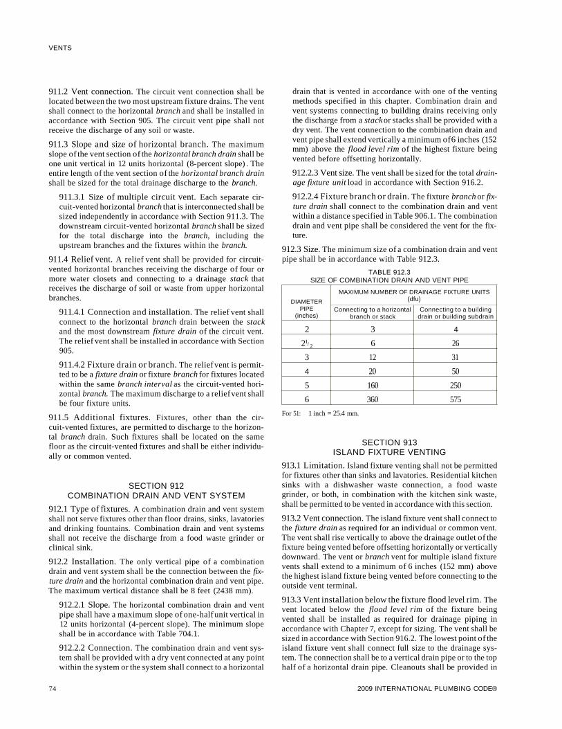
VENTS
911.2 Vent connection. The circuit vent connection shall belocated between the two most upstream fixture drains. The ventshall connect to the horizontal branch and shall be installed inaccordance with Section 905. The circuit vent pipe shall notreceive the discharge of any soil or waste.
911.3 Slope and size of horizontal branch. The maximumslope of the vent section of the horizontal branch drain shall beone unit vertical in 12 units horizontal (8-percent slope) . Theentire length of the vent section of the horizontal branch drainshall be sized for the total drainage discharge to the branch.
911.3.1 Size of multiple circuit vent. Each separate circuit-vented horizontal branch that is interconnected shall besized independently in accordance with Section 911.3. Thedownstream circuit-vented horizontal branch shall be sizedfor the total discharge into the branch, including theupstream branches and the fixtures within the branch.
911.4 Relief vent. A relief vent shall be provided for circuitvented horizontal branches receiving the discharge of four ormore water closets and connecting to a drainage stack thatreceives the discharge of soil or waste from upper horizontalbranches.
911.4.1 Connection and installation. The relief vent shallconnect to the horizontal branch drain between the stackand the most downstream fixture drain of the circuit vent.The relief vent shall be installed in accordance with Section905.
911.4.2 Fixture drain or branch. The relief vent is permitted to be a fixture drain or fixture branch for fixtures locatedwithin the same branch interval as the circuit-vented horizontal branch. The maximum discharge to a reliefvent shallbe four fixture units.
911.5 Additional fixtures. Fixtures, other than the circuit-vented fixtures, are permitted to discharge to the horizontal branch drain. Such fixtures shall be located on the samefloor as the circuit-vented fixtures and shall be either individually or common vented.
SECTION 912COMBINATION DRAIN AND VENT SYSTEM
912.1 Type of fixtures. A combination drain and vent systemshall not serve fixtures other than floor drains, sinks, lavatoriesand drinking fountains. Combination drain and vent systemsshall not receive the discharge from a food waste grinder orclinical sink.
912.2 Installation. The only vertical pipe of a combinationdrain and vent system shall be the connection between the fixture drain and the horizontal combination drain and vent pipe.The maximum vertical distance shall be 8 feet (2438 mm).
912.2.1 Slope. The horizontal combination drain and ventpipe shall have a maximum slope of one-half unit vertical in12 units horizontal (4-percent slope). The minimum slopeshall be in accordance with Table 704.1.
912.2.2 Connection. The combination drain and vent system shall be provided with a dry vent connected at any pointwithin the system or the system shall connect to a horizontal
74
drain that is vented in accordance with one of the ventingmethods specified in this chapter. Combination drain andvent systems connecting to building drains receiving onlythe discharge from a stackor stacks shall be provided with adry vent. The vent connection to the combination drain andvent pipe shall extend vertically a minimum of6 inches (152mm) above the flood level rim of the highest fixture beingvented before offsetting horizontally.
912.2.3 Vent size. The vent shall be sized for the total drainage fixture unit load in accordance with Section 916.2.
912.2.4 Fixture branch or drain. The fixture branch or fixture drain shall connect to the combination drain and ventwithin a distance specified in Table 906.1. The combinationdrain and vent pipe shall be considered the vent for the fixture.
912.3 Size. The minimum size of a combination drain and ventpipe shall be in accordance with Table 912.3.
TABLE 912.3SIZE OF COMBINATION DRAIN AND VENT PIPE
MAXIMUM NUMBER OF DRAINAGE FIXTURE UNITS
DIAMETER (dfu)
PIPE Connecting to a horizontal Connecting to a building(inches) branch or stack drain or building subdrain
2 3 4
21/ 2 6 26
3 12 31
4 20 50
5 160 250
6 360 575
For 51: 1 inch = 25.4 mm.
SECTION 913ISLAND FIXTURE VENTING
913.1 Limitation. Island fixture venting shall not be permittedfor fixtures other than sinks and lavatories. Residential kitchensinks with a dishwasher waste connection, a food wastegrinder, or both, in combination with the kitchen sink waste,shall be permitted to be vented in accordance with this section.
913.2 Vent connection. The island fixture vent shall connect tothe fixture drain as required for an individual or common vent.The vent shall rise vertically to above the drainage outlet of thefixture being vented before offsetting horizontally or verticallydownward. The vent or branch vent for multiple island fixturevents shall extend to a minimum of 6 inches (152 mm) abovethe highest island fixture being vented before connecting to theoutside vent terminal.
913.3 Vent installation below the fixture flood level rim. Thevent located below the flood level rim of the fixture beingvented shall be installed as required for drainage piping inaccordance with Chapter 7, except for sizing. The vent shall besized in accordance with Section 916.2. The lowest point of theisland fixture vent shall connect full size to the drainage system. The connection shall be to a vertical drain pipe or to the tophalf of a horizontal drain pipe. Cleanouts shall be provided in
2009 INTERNATIONAL PLUMBING CODE®

the island fixture vent to permit rodding of all vent pipinglocated below the flood level rim of the fixtures. Rodding inboth directions shall be permitted through a cleanout.
SECTION 914RELIEF VENTS-STACKS OF MORE THAN
10 BRANCH INTERVALS
914.1 Where required. Soil and waste stacks in buildings having more than 10 branch intervals shall be provided with arelief vent at each tenth interval installed, beginning with thetop floor.
914.2 Size and connection. The size of the relief vent shall beequal to the size of the vent stack to which it connects. Thelower end of each relief vent shall connect to the soil or wastestack through a wye below the horizontal branch serving thefloor, and the upper end shall connect to the vent stack througha wye not less than 3 feet (914 mm) above the floor.
SECTION 915VENTS FOR STACK OFFSETS
915.1 Vent for horizontal offset of drainage stack. Horizontal offsets of drainage stacks shall be vented where five or morebranch intervals are located above the offset. The offset shall
VENTS
be vented by venting the upper section of the drainage stackandthe lower section of the drainage stack.
915.2 Upper section. The upper section of the drainage stackshall be vented as a separate stackwith a vent stack connectioninstalled in accordance with Section 903.4. The offset shall beconsidered the base of the stack.
915.3 Lower section. The lower section of the drainage stackshall be vented by a yoke vent connecting between the offsetand the next lower horizontal branch. The yoke vent connection shall be permitted to be a vertical extension of the drainagestack. The size of the yoke vent and connection shall be a minimum of the size required for the vent stack of the drainagestack.
SECTION 916VENT PIPE SIZING
916.1 Size of stack vents and vent stacks. The minimumrequired diameter of stack vents and vent stacks shall be determined from the developed length and the total of drainage fixture units connected thereto in accordance with Table 916.1,but in no case shall the diameter be less than one-half the diameter of the drain served or less than 11/ 4 inches (32 mm).
TABLE 916.1SIZE AND DEVELOPED LENGTH OF STACK VENTS AND VENT STACKS
MAXIMUM DEVELOPED LENGTH OF VENT (feet)aDIAMETER OF SOIL OR TOTAL FIXTURE DIAMETER OF VENT (inches)
WASTE STACK UNITS BEING(inches) VENTED (dfu) 11
/ 4 11/ 2 2 21
/ 2 3 4 5 6 8 10 12
11/ 4 2 3011/ 2 8 50 150 - - - - - - - - -
11/ 2 10 30 100
2 12 30 75 2002 20 26 50 150 - - - - - - -
21/ 2 42 30 100 300
3 10 42 150 360 1,0403 21 - 32 110 270 810 - - - - - -
3 53 27 94 230 680
3 102 25 86 210 6204 43 - 35 85 250 980 - - - - -
4 140 27 65 200 750
4 320 23 55 170 6404 540 - - 21 50 150 580 - - - -
5 190 28 82 320 990
5 490 21 63 250 7605 940 - - - 18 53 210 670 - - - -
5 1,400 16 49 190 590
6 500 33 130 400 1,0006 1,100 - - - - 26 100 310 780 - - -
6 2,000 22 84 260 660
(continued)
2009 INTERNATIONAL PLUMBING CODE® 75

VENTS
TABLE 916.1-continuedSIZE AND DEVELOPED LENGTH OF STACK VENTS AND VENT STACKS
DIAMETER OF SOIL ORMAXIMUM DEVELOPED LENGTH OF VENT (feet)a
TOTAL FIXTURE DIAMETER OF VENT (inches)WASTE STACK UNITS BEING
(inches) VENTED (dfu) 11/ 4 11
/ 2 2 21/ 2 3 4 5 6 8 10 12
6 2,900 20 77 240 6008 1,800 - - - - 31 95 240 940 - -
8 3,400 24 73 190 720
8 5,600 20 62 160 6108 7,600 - - - - - 18 56 140 560 -
10 4,000 31 78 310 960
10 7,200 24 60 240 74010 11,000 - - - - - 20 51 200 630 -
10 15,000 18 46 180 570
12 7,300 31 120 380 94012 13,000 - - - - - - - 24 94 300 72012 20,000 20 79 250 610
12 26,000 18 72 230 50015 15,000 - - - - - - - 40 130 31015 25,000 31 96 240
15 38,000 26 81 20015 50,000
- - - - - - - -24 74 180
For 51: 1 inch = 25.4 mm, 1 foot = 304.8 mm.a. The developed length shall be measured from the vent connection to the open air.
916.2 Vents other than stack vents or vent stacks. The diameter of individual vents, branch vents, circuit vents and reliefvents shall be at least one-half the required diameter of thedrain served. The required size of the drain shall be determinedin accordance with Table 710.1 (2). Vent pipes shall not be lessthan 11/ 4 inches (32 mm) in diameter. Vents exceeding 40 feet(12 192 mm) in developed length shall be increased by onenominal pipe size for the entire developed length of the ventpipe. Relief vents for soil and waste stacks in buildings havingmore than 10 branch intervalsshall be sized in accordance withSection 914.2.
916.3 Developed length. The developed length of individual,branch, circuit and relief vents shall be measured from the farthest point of vent connection to the drainage system to thepoint of connection to the vent stack, stack vent or terminationoutside of the building.
916.4 Multiple branch vents. Where multiple branch ventsare connected to a common branch vent, the common branchvent shall be sized in accordance with this section based on thesize of the common horizontal drainage branch that is or wouldbe required to serve the total drainage fixture unit (diu) loadbeing vented.
916.4.1 Branch vents exceeding 40 feet in developedlength. Branch vents exceeding 40 feet (12 192 mm) indeveloped length shall be increased by one nominal size forthe entire developed length of the vent pipe.
76
916.5 Sump vents. Sump vent sizes shall be determined inaccordance with Sections 916.5.1 and 91 7.6.2.
916.5.1 Sewage pumps and sewage ejectors other thanpneumatic. Drainage piping below sewer level shall bevented in a similar manner to that ofa gravity system. Building sump vent sizes for sumps with sewage pumps or sewage ejectors, other than pneumatic, shall be determined inaccordance with Table 916.5.1.
916.5.2 Pneumatic sewage ejectors. The air pressure reliefpipe from a pneumatic sewage ejector shall be connected toan independent vent stack terminating as required for ventextensions through the roof. The relief pipe shall be sized torelieve air pressure inside the ejector to atmospheric pressure, but shall not be less than 11/ 4 inches (32 mm) in size.
SECTION 917AIR ADMITTANCE VALVES
917.1 General. Vent systems utilizing air admittance valvesshall comply with this section. Stack-type air admittancevalves shall conform to ASSE 1050. Individual andbranch-type air admittance valves shall conform to ASSE1051.
917.2 Installation. The valves shall be installed in accordancewith the requirements of this section and the manufacturer'sinstallation instructions. Air admittance valves shall beinstalled after the DWV testing required by Section 312.2 or312.3 has been performed.
2009 INTERNATIONAL PLUMBING CODE®

VENTS
TABLE 916.5.1SIZE AND LENGTH OF SUMP VENTS
MAXIMUM DEVELOPED LENGTH OF VENT (feet)a
DISCHARGE CAPACITY Diameter of vent (inches)OF PUMP
(gpm) 11/ 4 11
/ 2 2 21/ 2 3 4
10 No limitb No limit No limit No limit No limit No limit
20 270 No limit No limit No limit No limit No limit
40 72 160 No limit No limit No limit No limit
60 31 75 270 No limit No limit No limit
80 16 41 150 380 No limit No limit
100 10c 25 97 250 No limit No limit
150 Not permitted 10c 44 110 370 No limit
200 Not permitted Not permitted 20 60 210 No limit
250 Not permitted Not permitted 10 36 132 No limit
300 Not permitted Not permitted 10c 22 88 380
400 Not permitted Not permitted Not permitted 10c 44 210
500 Not permitted Not permitted Not permitted Not permitted 24 130
For SI: 1 inch = 25.4 mm, 1 foot = 304.8 mm, 1 gallon per minute = 3.785 Lim.a. Developed length plus an appropriate allowance for entrance losses and friction due to fittings , changes in direction and diameter. Suggested allowances shall be
obtained from NSB Monograph 31 or other approved sources. An allowance of 50 percent of the developed length shall be assumed if a more precise value is notavailable.
b. Actual values greater than 500 feet.c. Less than 10 feet.
I
917.3 Where permitted. Individual, branch and circuit ventsshall be permitted to terminate with a connection to an individual or branch-type air admittance valve. Stack vents and ventstacks shall be permitted to terminate to stack-type air admittance valves. Individual and branch-type air admittance valvesshall vent only fixtures that are on the same floor level and connect to a horizontal branch drain. The horizontal branch drainhaving individual and branch-type air admittance valves shallconform to Section 917.3.1 or 917.3.2. Stack-type air admittance valves shall conform to Section 917.3.3.
917.3.1 Location of branch. The horizontal branch drainshall connect to the drainage stackor bUilding drain a maximum of four branch intervals from the top of the stack.
917.3.2 Reliefvent. Where the horizontal branch is locatedmore than four branch intervals from the top of the stack,the horizontal branch shall be provided with a relief ventthat shall connect to a vent stackor stack vent, or extend outdoors to the open air. The reliefvent shall connect to the horizontal branch drain between the stack and the mostdownstream fixture drain connected to the horizontalbranch drain. The relief vent shall be sized in accordancewith Section 916.2 and installed in accordance with Section905. The relief vent shall be permitted to serve as the ventfor other fixtures .
917.3.3 Stack. Stack-type air admittance valves shall notserve as the vent terminal for vent stacks or stack vents thatserve drainage stacks having more than six branch intervals.
917.4 Location. Individual and branch-type air admittancevalves shall be located a minimum of 4 inches (102 mm) above
2009 INTERNATIONAL PLUMBING CODE®
the horizontal branch drain or fixture drain being vented.Stack-type air admittance valves shall be located not less than 6inches (152 mm) above the flood levelrim of the highest fixturebeing vented. The air admittance valve shall be located withinthe maximum developed length permitted for the vent. The airadmittance valve shall be installed a minimum of 6 inches (152mm) above insulation materials.
917.5 Access and ventilation. Access shall be provided to allair admittance valves. The valve shall be located within a venti1ated space that allows air to enter the valve.
917.6 Size. The air admittance valve shall be rated in accordance with the standard for the size of the vent to which thevalve is connected.
917.7 Vent required. Within each plumbing system, a minimum of one stack ventor vent stackshall extend outdoors to theopen air.
917.8 Prohibited installations. Air admittance valves shallnot be installed in nonneutralized special waste systems asdescribed in Chapter 8. Air admittance valves shall not belocated in spaces utilized as supply or return air plenums. Airadmittance valves without an engineered design shall not beutilized to vent sumps or tanks of any type.
SECTION 918ENGINEERED VENT SYSTEMS
918.1 General. Engineered vent systems shall comply withthis section and the design, submittal, approval, inspection andtesting requirements of Section 105.4.
77

VENTS
918.2 Individual branch fixture and individual fixtureheader vents. The maximum developed length of individualfixture vents to vent branches and vent headers shall be determined in accordance with Table 918.2 for the minimum pipediameters at the indicated vent airflow rates.
The individual vent airflow rate shall be determined inaccordance with the following:
(Equation 9-1)
For 51: Qh,b = Nn,bQv (0.4719 Lis)
where:
Nn,b = Number of fixtures per header (or vent branch) + totalnumber of fixtures connected to vent stack.
Qh,b = Vent branch or vent header airflow rate (cfm).
Qv = Total vent stack airflow rate (cfm).
Qv (gpm) = 27.8 rs2/3 (1 - r) D 8/3
Qv (cfm) = 0.134 Qv (gpm)
where:
D = Drainage stack diameter (inches).
Qw = Design discharge load (gpm).
r s = Waste water flow area to total area.
27.8 D8/3
Individual vent airflow rates are obtained by equally distributing Qh,b into one-half the total number of fixtures on thebranch or header for more than two fixtures; for an odd numberof total fixtures, decrease by one; for one fixture, apply the fullvalue of Qh,b'
Individual vent developed length shall be increased by 20percent of the distance from the vent stack to the fixture ventconnection on the vent branch or header.
SECTION 919COMPUTERIZED VENT DESIGN
919.1 Design of vent system. The sizing, design and layout ofthe vent system shall be permitted to be determined by approvedcomputer program design methods.
919.2 System capacity. The vent system shall be based on theair capacity requirements of the drainage system under a peakload condition.
TABLE 918.2MINIMUM DIAMETER AND MAXIMUM LENGTH OF INDIVIDUAL BRANCH FIXTURE VENTS AND
INDIVIDUAL FIXTURE HEADER VENTS FOR SMOOTH PIPES
INDIVIDUAL VENT AIRFLOW RATE (cubic feet per minute)
DIAMETER OF Maximum developed length of vent (feet)VENT PIPE
(inches) 1 2 3 4 5 6 7 8 9 10 11 12 13 14 15 16 17 18 19 20
1/2 95 25 13 8 5 4 3 2 1 1 1 1 1 1 1 1 1 1 1 1
3/4 100 88 47 30 20 15 10 9 7 6 5 4 3 3 3 2 2 2 2 1
1 - - 100 94 65 48 37 29 24 20 17 14 12 11 9 8 7 7 6 6
11/ 4 - - - - - - - 100 87 73 62 53 46 40 36 32 29 26 23 21
11/ 2 - - - - - - - - - - - 100 96 84 75 65 60 54 49 45
2 - - - - - - - - - - - - - - - - - - - 100
For SI: 1 inch = 25.4 mm, 1 cubic foot per minute = 0.4719 Lis, 1 foot = 304.8 mm.
78 2009 INTERNATIONAL PLUMBING CODE®

CHAPTER 10
TRAPS, INTERCEPTORS AND SEPARATORS
SECTION 1001GENERAL
1001.1 Scope. This chapter shall govern the material andinstallation of traps, interceptors and separators.
SECTION 1002TRAP REQUIREMENTS
1002.1 Fixture traps. Each plumbing fixture shall be separately trapped by a liquid-seal trap, except as otherwise permitted by this code. The vertical distance from the fixture outlet tothe trap weir shall not exceed 24 inches (610 mm), and the horizontal distance shall not exceed 30 inches (610 mm) measuredfrom the centerline of the fixture outlet to the centerline of theinlet of the trap. The height ofa clothes washer standpipe abovea trap shall conform to Section 802.4. A fixture shall not bedouble trapped.
Exceptions:
1. This section shall not apply to fixtures with integraltraps.
2. A combination plumbing fixture is permitted to beinstalled on one trap, provided that one compartmentis not more than 6 inches (152 mm) deeper than theother compartment and the waste outlets are not morethan 30 inches (762 mm) apart.
3. A grease interceptor intended to serve as a fixture trapin accordance with the manufacturer's installationinstructions shall be permitted to serve as the trap for asingle fixture or a combination sink of not more thanthree compartments where the vertical distance fromthe fixture outlet to the inlet of the interceptor does notexceed 30 inches (762 mm) and the developed lengthof the waste pipe from the most upstream fixture outlet to the inlet of the interceptor does not exceed 60inches (1524 mm).
1002.2 Design of traps. Fixture traps shall be self-scouring.Fixture traps shall not have interior partitions, except wheresuch traps are integral with the fixture or where such traps areconstructed of an approved material that is resistant to corrosion and degradation. Slip joints shall be made with anapproved elastomeric gasket and shall be installed only on thetrap inlet, trap outlet and within the trap seal.
1002.3 Prohibited traps. The following types of traps are prohibited:
1. Traps that depend on moving parts to maintain the seal.
2. Bell traps.
3. Crown-vented traps.
4. Traps not integral with a fixture and that depend on interior partitions for the seal, except those traps constructed
2009 INTERNATIONAL PLUMBING CODE®
of an approved material that is resistant to corrosion anddegradation.
5. "S" traps.
6. Drum traps.
Exception: Drum traps used as solids interceptorsand drum traps serving chemical waste systems shallnot be prohibited.
1002.4 Trap seals. Each fixture trap shall have a liquid seal ofnot less than 2 inches (51 mm) and not more than 4 inches (102mm), or deeper for special designs relating to accessible fixtures. Where a trap seal is subject to loss by evaporation, a trapseal primer valve shall be installed. Trap seal primer valvesshall connect to the trap at a point above the level of the trapseal. A trap seal primer valve shall conform to ASSE 1018 orASSE 1044.
1002.5 Size of fixture traps. Fixture trap size shall be sufficient to drain the fixture rapidly and not less than the size indicated in Table 709.1. A trap shall not be larger than the drainagepipe into which the trap discharges.
1002.6 Building traps. Building (house) traps shall be prohibited, except where local conditions necessitate such traps.Building traps shall be provided with a cleanout and a reliefvent or fresh air intake on the inlet side of the trap. The size ofthe relief vent or fresh air intake shall not be less than one-halfthe diameter of the drain to which the relief vent or air intakeconnects. Such relief vent or fresh air intake shall be carriedabove grade and shall be terminated in a screened outlet locatedoutside the building.
1002.7 Trap setting and protection. Traps shall be set levelwith respect to the trap seal and, where necessary, shall be protected from freezing.
1002.8 Recess for trap connection. A recess provided for connection of the underground trap, such as one serving a bathtubin slab-type construction, shall have sides and a bottom of corrosion-resistant, insect-and verminproof construction.
1002.9 Acid-resisting traps. Where a vitrified clay or otherbrittleware, acid-resisting trap is installed underground, suchtrap shall be embedded in concrete extending 6 inches (152mm) beyond the bottom and sides of the trap.
1002.10 Plumbing in mental health centers. In mental healthcenters, pipes and traps shall not be exposed.
SECTION 1003INTERCEPTORS AND SEPARATORS
1003.1 Where required. Interceptors and separators shall beprovided to prevent the discharge of oil, grease, sand and othersubstances harmful or hazardous to the building drainage system, the public seweJ; the private sewage disposal system or thesewage treatment plant or processes.
79
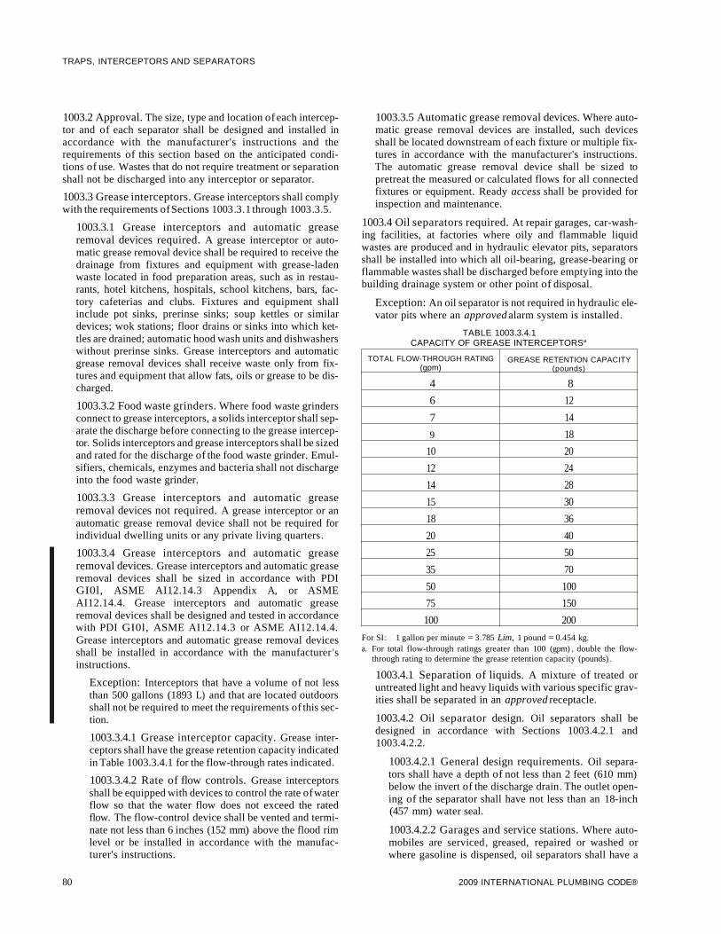
TRAPS, INTERCEPTORS AND SEPARATORS
1003.2 Approval. The size, type and location of each interceptor and of each separator shall be designed and installed inaccordance with the manufacturer's instructions and therequirements of this section based on the anticipated conditions of use. Wastes that do not require treatment or separationshall not be discharged into any interceptor or separator.
1003.3 Grease interceptors. Grease interceptors shall complywith the requirements ofSections 1003.3.1 through 1003.3.5.
1003.3.1 Grease interceptors and automatic greaseremoval devices required. A grease interceptor or automatic grease removal device shall be required to receive thedrainage from fixtures and equipment with grease-ladenwaste located in food preparation areas, such as in restaurants, hotel kitchens, hospitals, school kitchens, bars, factory cafeterias and clubs. Fixtures and equipment shallinclude pot sinks, prerinse sinks; soup kettles or similardevices; wok stations; floor drains or sinks into which kettles are drained; automatic hood wash units and dishwasherswithout prerinse sinks. Grease interceptors and automaticgrease removal devices shall receive waste only from fixtures and equipment that allow fats, oils or grease to be discharged.
1003.3.2 Food waste grinders. Where food waste grindersconnect to grease interceptors, a solids interceptor shall separate the discharge before connecting to the grease interceptor. Solids interceptors and grease interceptors shall be sizedand rated for the discharge of the food waste grinder. Emulsifiers, chemicals, enzymes and bacteria shall not dischargeinto the food waste grinder.
1003.3.3 Grease interceptors and automatic greaseremoval devices not required. A grease interceptor or anautomatic grease removal device shall not be required forindividual dwelling units or any private living quarters.
1003.3.4 Grease interceptors and automatic greaseremoval devices. Grease interceptors and automatic greaseremoval devices shall be sized in accordance with PDIGI0l, ASME AI12.14.3 Appendix A, or ASMEAI12.14.4. Grease interceptors and automatic greaseremoval devices shall be designed and tested in accordancewith PDI GI0l, ASME AI12.14.3 or ASME AI12.14.4.Grease interceptors and automatic grease removal devicesshall be installed in accordance with the manufacturer 'sinstructions.
Exception: Interceptors that have a volume of not lessthan 500 gallons (1893 L) and that are located outdoorsshall not be required to meet the requirements of this section.
1003.3.4.1 Grease interceptor capacity. Grease interceptors shall have the grease retention capacity indicatedin Table 1003.3.4.1 for the flow-through rates indicated.
1003.3.4.2 Rate of flow controls. Grease interceptorsshall be equipped with devices to control the rate ofwaterflow so that the water flow does not exceed the ratedflow. The flow-control device shall be vented and terminate not less than 6 inches (152 mm) above the flood rimlevel or be installed in accordance with the manufacturer's instructions.
80
1003.3.5 Automatic grease removal devices. Where automatic grease removal devices are installed, such devicesshall be located downstream of each fixture or multiple fixtures in accordance with the manufacturer's instructions.The automatic grease removal device shall be sized topretreat the measured or calculated flows for all connectedfixtures or equipment. Ready access shall be provided forinspection and maintenance.
1003.4 Oil separators required. At repair garages, car-washing facilities, at factories where oily and flammable liquidwastes are produced and in hydraulic elevator pits, separatorsshall be installed into which all oil-bearing, grease-bearing orflammable wastes shall be discharged before emptying into thebuilding drainage system or other point of disposal.
Exception: An oil separator is not required in hydraulic elevator pits where an approved alarm system is installed.
TABLE 1003.3.4.1CAPACITY OF GREASE INTERCEPTORSa
TOTAL FLOW-THROUGH RATING GREASE RETENTION CAPACITY(gpm) (pounds)
4 8
6 12
7 14
9 18
10 20
12 24
14 28
15 30
18 36
20 40
25 50
35 70
50 100
75 150
100 200
For SI: 1 gallon per minute = 3.785 Lim, 1 pound = 0.454 kg.a. For total flow-through ratings greater than 100 (gpm) , double the flow-
through rating to determine the grease retention capacity (pounds) .
1003.4.1 Separation of liquids. A mixture of treated oruntreated light and heavy liquids with various specific gravities shall be separated in an approved receptacle.
1003.4.2 Oil separator design. Oil separators shall bedesigned in accordance with Sections 1003.4.2.1 and1003.4.2.2.
1003.4.2.1 General design requirements. Oil separators shall have a depth of not less than 2 feet (610 mm)below the invert of the discharge drain. The outlet opening of the separator shall have not less than an 18-inch(457 mm) water seal.
1003.4.2.2 Garages and service stations. Where automobiles are serviced, greased, repaired or washed orwhere gasoline is dispensed, oil separators shall have a
2009 INTERNATIONAL PLUMBING CODE®

minimum capacity of6 cubic feet (0.168 m3) for the first100 square feet (9.3 m2) of area to be drained, plus 1cubic foot (0.28 m3) for each additional 100 square feet(9.3 m2) of area to be drained into the separator. Parkinggarages in which servicing, repairing or washing is notconducted, and in which gasoline is not dispensed, shallnot require a separator. Areas of commercial garages utilized only for storage of automobiles are not required tobe drained through a separator.
1003.5 Sand interceptors in commercial establishments.Sand and similar interceptors for heavy solids shall be designedand located so as to be provided with ready access for cleaning,and shall have a water seal ofnot less than 6 inches (152 mm).
1003.6 Laundries. Laundry facilities not installed within anindividual dwelling unit or intended for individual family useshall be equipped with an interceptor with a wire basket or similar device, removable for cleaning, that prevents passage intothe drainage system of solids 1/2 inch (12.7 mm) or larger insize, string, rags, buttons or other materials detrimental to thepublic sewage system.
1003.7 Bottling establishments. Bottling plants shall discharge process wastes into an interceptor that will provide forthe separation of broken glass or other solids before discharging waste into the drainage system.
1003.8 Slaughterhouses. Slaughtering room and dressingroom drains shall be equipped with approved separators. Theseparator shall prevent the discharge into the drainage systemof feathers, entrails and other materials that cause clogging.
1003.9 Venting of interceptors and separators. Interceptorsand separators shall be designed so as not to become air boundwhere tight covers are utilized. Each interceptor or separatorshall be vented where subject to a loss of trap seal.
1003.10 Access and maintenance of interceptors and separators. Access shall be provided to each interceptor and separator for service and maintenance. Interceptors and separatorsshall be maintained by periodic removal of accumulatedgrease, scum, oil, or other floating substances and solids deposited in the interceptor or separator.
SECTION 1004MATERIALS, JOINTS AND CONNECTIONS
1004.1 General. The materials and methods utilized for theconstruction and installation of traps, interceptors and separators shall comply with this chapter and the applicable provisions of Chapters 4 and 7. The fittings shall not have ledges,shoulders or reductions capable of retarding or obstructingflow of the piping.
2009 INTERNATIONAL PLUMBING CODE®
TRAPS, INTERCEPTORS AND SEPARATORS
81

82 2009 INTERNATIONAL PLUMBING CODE®

CHAPTER 11
STORM DRAINAGE
SECTION 1101GENERAL
1101.1 Scope. The provisions of this chapter shall govern thematerials, design, construction and installation of storm drainage.
1101.2 Where required. All roofs, paved areas, yards, courtsand courtyards shall drain into a separate storm sewer system,or a combined sewer system, or to an approved place of disposal. For one- and two-family dwellings, and whereapproved, storm water is permitted to discharge onto flat areas,such as streets or lawns, provided that the storm water flowsaway from the building.
1101.3 Prohibited drainage. Storm water shall not be drainedinto sewers intended for sewage only.
1101.4 Tests. The conductors and the building storm drainshall be tested in accordance with Section 312.
1101.5 Change in size. The size of a drainage pipe shall not bereduced in the direction of flow.
1101.6 Fittings and connections. All connections andchanges in direction of the storm drainage system shall bemade with approved drainage-type fittings in accordance withTable 706.3. The fittings shall not obstruct or retard flow in thesystem.
1101.7 Roofdesign. Roofs shall be designed for the maximumpossible depth ofwater that will pond thereon as determined bythe relative levels of roof deck and overflow weirs, scuppers,edges or serviceable drains in combination with the deflectedstructural elements. In determining the maximum possibledepth of water, all primary roof drainage means shall beassumed to be blocked.
1101.8 Cleanouts required. Cleanouts shall be installed in thestorm drainage system and shall comply with the provisions ofthis code for sanitary drainage pipe cleanouts.
Exception: Subsurface drainage system.
11101.9 Backwater valves. Storm drainage systems shall beprovided with backwater valves as required for sanitary drainage systems in accordance with Section 715.
SECTION 1102MATERIALS
1102.1 General. The materials and methods utilized for theconstruction and installation of storm drainage systems shallcomply with this section and the applicable provisions ofChapter 7.
1102.2 Inside storm drainage conductors. Inside stormdrainage conductors installed above ground shall conform toone of the standards listed in Table 702.1.
2009 INTERNATIONAL PLUMBING CODE®
1102.3 Underground building storm drain pipe. Underground building storm drain pipe shall conform to one of thestandards listed in Table 702.2.
1102.4 Building storm sewer pipe. Building storm sewerpipeshall conform to one of the standards listed in Table 1102.4.
TABLE 1102.4BUILDING STORM SEWER PIPE
MATERIAL STANDARD
Acrylonitrile butadieneASTM D 2661; ASTM D 2751;ASTM F 628; CAN/CSA BI81.1;
styrene (ABS) plastic pipeCAN/CSA B182.1
Asbestos-cement pipe ASTM C 428
Cast-iron pipeASTM A 74; ASTM A 888;CISPI301
ASTM C 14; ASTM C 76;Concrete pipe CAN/CSA A257.1M;
CAN/CSA A257.2M
Copper or copper-alloyASTM B 75; ASTM B 88;
tubing (Type K, L, M orASTM B 251; ASTM B 306DWV)
Polyethylene (PE) plasticASTM F 2306/F 2306Mpipe
Polyvinyl chloride (PVC)ASTM D 2665; ASTM D 3034;
plastic pipe (Type DWV,ASTM F 891; CSA BI82.4;
SDR26, SDR35, SDR41,CSA BI81.2; CSA B182.2
PS50 or PS100)
Vitrified clay pipe ASTM C 4; ASTM C 700
Stainless steel drainageASME AI12.3.1
systems, Type 316L
1102.5 Subsoil drain pipe. Subsoil drains shall beopen-jointed, horizontally split or perforated pipe conformingto one of the standards listed in Table 1102.5.
TABLE 1102.5SUBSOIL DRAIN PIPE
MATERIAL STANDARD
Asbestos-cement pipe ASTM C 508
Cast-iron pipeASTM A 74; ASTM A 888;CISPI301
ASTM F 405;Polyethylene (PE) plastic pipe CAN/CSA BI82.1;
CSA BI82.6; CSA B182.8
Polyvinyl chloride (PVC) ASTM D 2729; ASTM F 891;Plastic pipe (type sewer pipe, CSA BI82.2;PS25, PS50 or PSI00) CAN/CSA B182.4
Stainless steel drainage systems,ASME A 112.3.1
Type 316L
Vitrified clay pipe ASTM C 4; ASTM C 700
1102.6 Roof drains. Roof drains shall conform to ASMEAI12.21.2M or ASME AI12.3.1.
83
I

I
STORM DRAINAGE
1102.7 Fittings. Pipe fittings shall be approvedfor installationwith the piping material installed, and shall conform to therespective pipe standards or one of the standards listed in Table1102.7. The fittings shall not have ledges, shoulders or reductions capable of retarding or obstructing flow in the piping.Threaded drainage pipe fittings shall be of the recessed drainage type.
TABLE 1102.7PIPE FITTINGS
MATERIAL STANDARD
Acrylonitrile butadiene ASTM D 2661; ASTM D 3311;styrene (ABS) plastic CSA B18!.1
ASME BI6.4; ASME BI6.12;Cast-iron ASTM A 888; CISPI 301;
ASTM A 74
Coextruded composite ABSsewer and drain DR-PS in
ASTM D 2751PS35,PS50, PSI00, PS140,PS200
Coextruded composite ABSASTM D 2661; ASTM D 3311;
DWV Schedule 40 IPS pipeASTM F 628
(solid or cellular core)
Coextruded composite PVCDWV Schedule 40 IPS-DR, ASTM D 2665; ASTM D 3311;PS140, PS200 (solid or ASTM F 891cellular core)
Coextruded composite PVCsewer and drain DR-PS in
ASTM D 3034PS35,PS50, PSI00, PS140,PS200
ASME BI6.15; ASME BI6.18;Copper or copper alloy ASME BI6.22; ASME BI6.23;
ASME BI6.26; ASME B16.29
Gray iron and ductile iron AWWACII0
Malleable iron ASME B16.3
Plastic, general ASTM F 409
Polyethylene (PE) plastic pipe ASTM F 2306/F 2306M
Polyvinyl chloride (PVC) ASTM D 2665; ASTM D 3311;plastic ASTM F 1866
SteelASME BI6.9; ASME BI6.11;ASME B16.28
Stainless steel drainageASME AI12.3.1
systems, Type 316L
SECTION 1103TRAPS
1103.1 Main trap. Leaders and storm drains connected to acombined sewershall be trapped. Individual storm water trapsshall be installed on the storm water drain branch serving eachconductor, or a single trap shall be installed in the main storm
84
drain just before its connection with the combined buildingsewer or the public sewer.
1103.2 Material. Storm water traps shall be of the same material as the piping system to which they are attached.
1103.3 Size. Traps for individual conductors shall be the samesize as the horizontal drain to which they are connected.
1103.4 Cleanout. An accessible cleanout shall be installed onthe building side of the trap.
SECTION 1104CONDUCTORS AND CONNECTIONS
1104.1 Prohibited use. Conductor pipes shall not be used assoil, waste or vent pipes, and soil, waste or vent pipes shall notbe used as conductors.
1104.2 Combining storm with sanitary drainage. The sanitary and storm drainage systems of a structure shall be entirelyseparate except where combined sewer systems are utilized.Where a combined sewer is utilized, the building storm drainshall be connected in the same horizontal plane through a single-wye fitting to the combined sewer at least 10 feet (3048mm) downstream from any soil stack.
1104.3 Floor drains. Floor drains shall not be connected to astorm drain.
SECTION 1105ROOF DRAINS
1105.1 Strainers. Roof drains shall have strainers extendingnot less than 4 inches (102 mm) above the surface of the roofimmediately adjacent to the roof drain. Strainers shall have anavailable inlet area, above roof level, of not less than one andone-half times the area of the conductor or leader to which thedrain is connected.
1105.2 Flat decks. Roof drain strainers for use on sun decks,parking decks and similar areas that are normally serviced andmaintained shall comply with Section 1105.1 or shall be of theflat-surface type, installed level with the deck, with an availableinlet area not less than two times the area of the conductor orleader to which the drain is connected.
1105.3 Roof drain flashings. The connection between roofsand roof drains which pass through the roof and into the interior of the building shall be made water-tight by the use ofapproved flashing material.
SECTION 1106SIZE OF CONDUCTORS, LEADERS
AND STORM DRAINS
1106.1 General. The size of the vertical conductors and leaders' building storm drains, building storm sewers, and any horizontal branches of such drains or sewers shall be based on the100-year hourly rainfall rate indicated in Figure 1106.1 or onother rainfall rates determined from approved local weatherdata.
2009 INTERNATIONAL PLUMBING CODE®

STORM DRAINAGE
4.2a.JW ~'
FIGURE 1106.1100-YEAR, l-HOUR RAINFALL (INCHES) EASTERN UNITED STATES
For SI: 1 inch = 25.4 mm.Source: National Weather Service, National Oceanic and Atmospheric Administration, Washington D.C.
2009 INTERNATIONAL PLUMBING CODE® 85

STORM DRAINAGE
FIGURE 1106.l-continued100-YEAR, l-HOUR RAINFALL (INCHES) CENTRAL UNITED STATES
For SI: 1 inch = 25.4 mm.Source: National Weather Service, National Oceanic and Atmospheric Administration, Washington D.C.
86 2009 INTERNATIONAL PLUMBING CODE®

1.5
FIGURE 1106.1-continued100-YEAR, 1-HOUR RAINFALL (INCHES) WESTERN UNITED STATES
For SI: 1 inch = 25.4 mm.Source: National Weather Service, National Oceanic and Atmospheric Administration, Washington D.C.
2009 INTERNATIONAL PLUMBING CODE®
STORM DRAINAGE
87
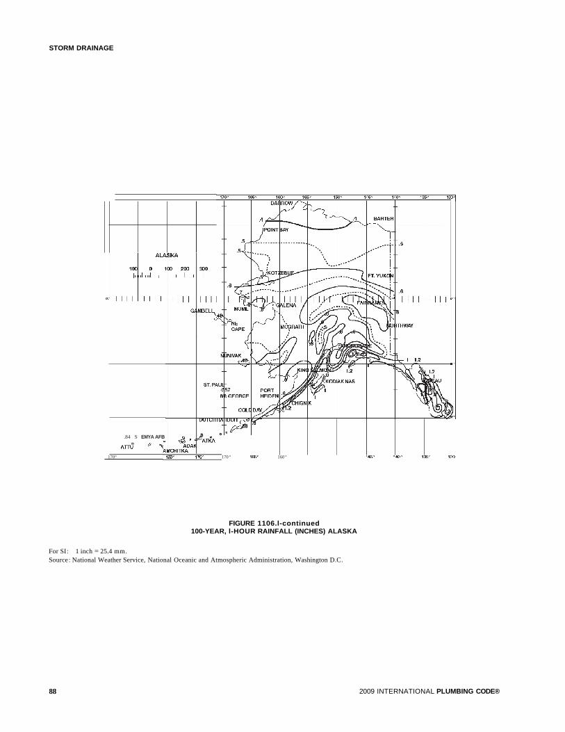
STORM DRAINAGE
170°
.84 S EMYA AFB
ATTU & ","
170 ° 166 ° 160° 146 ° 140 ° 136° 13)
FIGURE 1106.l-continued100-YEAR, l-HOUR RAINFALL (INCHES) ALASKA
For SI: 1 inch = 25.4 mm.Source: National Weather Service, National Oceanic and Atmospheric Administration, Washington D.C.
88 2009 INTERNATIONAL PLUMBING CODE®
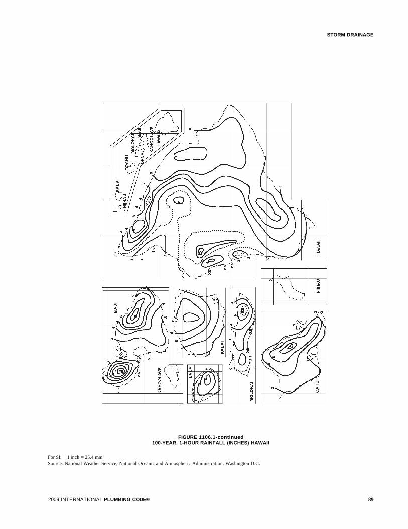
FIGURE 1106.1-continued100-YEAR, 1-HOUR RAINFALL (INCHES) HAWAII
For SI: 1 inch = 25.4 mm.Source: National Weather Service, National Oceanic and Atmospheric Administration, Washington D.C.
2009 INTERNATIONAL PLUMBING CODE®
STORM DRAINAGE
89

I
STORM DRAINAGE
TABLE 1106.2(1)SIZE OF CIRCULAR VERTICAL CONDUCTORS AND LEADERS
HORIZONTALLY PROJECTED ROOF AREA (square feet)
DIAMETER OF Rainfall rate (inches per hour)LEADER(inches)a 1 2 3 4 5 6 7 8 9 10 11 12
2 2,880 1,440 960 720 575 480 410 360 320 290 260 240
3 8,800 4,400 2,930 2,200 1,760 1,470 1,260 1,100 980 880 800 730
4 18,400 9,200 6,130 4,600 3,680 3,070 2,630 2,300 2,045 1,840 1,675 1,530
5 34,600 17,300 11,530 8,650 6,920 5,765 4,945 4,325 3,845 3,460 3,145 2,880
6 54,000 27,000 17,995 13,500 10,800 9,000 7,715 6,750 6,000 5,400 4,910 4,500
8 116,000 58,000 38,660 29,000 23,200 19,315 16,570 14,500 12,890 11,600 10,545 9,600
For SI: 1 inch = 25.4 mm, 1 square foot = 0.0929 m2•
I a. Sizes indicated are the diameter ofcircular piping. This table is applicable to piping ofother shapes,provided the cross-sectional shape fully encloses a circle ofthediameter indicated in this table. For rectangular leaders, see Table 1106.2 (2) . Interpolation is permitted for pipe sizes that fall between those listed in this table.
TABLE 1106.2(2)SIZE OF RECTANGULAR VERTICAL CONDUCTORS AND LEADERS
HORIZONTALLY PROJECTED ROOF AREA (square feet)
DIMENSIONS OF Rainfall rate (inches per hour)COMMON LEADER SIZESwidth x length (inches)a 1 2 3 4 5 6 7 8 9 10 11 12
13/ 4 x 21/ 2 3,410 1,700 1,130 850 680 560 480 420 370 340 310 280
2x3 5,540 2,770 1,840 1,380 1,100 920 790 690 610 550 500 460
23/ 4 x 41/ 4 12,830 6,410 4,270 3,200 2,560 2,130 1,830 1,600 1,420 1,280 1,160 1,060
3x4 13,210 6,600 4,400 3,300 2,640 2,200 1,880 1,650 1,460 1,320 1,200 1,100
31/ 2 x 4 15,900 7,950 5,300 3,970 3,180 2,650 2,270 1,980 1,760 1,590 1,440 1,320
31/ 2 x 5 21,310 10,650 7,100 5,320 4,260 3,550 3,040 2,660 2,360 2,130 1,930 1,770
33/ 4 x 43/ 4 21,960 10,980 7,320 5,490 4,390 3,660 3,130 2,740 2,440 2,190 1,990 1,830
33/ 4 x 51/ 4 25,520 12,760 8,500 6,380 5,100 4,250 3,640 3,190 2,830 2,550 2,320 2,120
31/ 2 x 6 27,790 13,890 9,260 6,940 5,550 4,630 3,970 3,470 3,080 2,770 2,520 2,310
4x6 32,980 16,490 10,990 8,240 6,590 5,490 4,710 4,120 3,660 3,290 2,990 2,740
51/ 2 x 51/ 2 44,300 22,150 14,760 11 ,070 8,860 7,380 6,320 5,530 4,920 4,430 4,020 3,690
71/ 2 x 71/ 2 100,500 50,250 33,500 25,120 20,100 16,750 14,350 12,560 11,160 10,050 9,130 8,370
a. Sizes indicated are nominal width x length of the opening for rectangular piping.b. For shapes not included in this table, Equation 11-1 shall be used to determine the equivalent circular diameter, De' of rectangular piping for use in interpolation
using the data from Table 1106.2(1) .
De= [width x length] 112 (Equation II-I)
where:
De= equivalent circular diameter and De' width and length are in inches.
90 2009 INTERNATIONAL PLUMBING CODE®

11106.2 Vertical conductors and leaders. Vertical conductorsand leaders shall be sized for the maximum projected roof area,in accordance with Tables 1106.2(1) and 1106.2(2).
1106.3 Building storm drains and sewers. The size of thebuilding storm drain, building storm sewerand their horizontalbranches having a slope of one-half unit or less vertical in 12units horizontal (4-percent slope) shall be based on the maximum projected roof area in accordance with Table 1106.3. Theminimum slope of horizontal branches shall be one-eighth unitvertical in 12 units horizontal (1-percent slope) unless otherwise approved.
1106.4 Vertical walls. In sizing roof drains and storm drainagepiping, one-halfof the area ofany vertical wall that diverts rainwater to the roof shall be added to the projected roof area forinclusion in calculating the required size of vertical conductors, leaders and horizontal storm drainage piping.
1106.5 Parapet wall scupper location. Parapet wall roofdrainage scupper and overflow scupper location shall complywith the requirements of the International Building Code.
STORM DRAINAGE
1106.6 Size of roof gutters. The size of semicircular guttersshall be based on the maximum projected roof area in accordance with Table 1106.6.
SECTION 1107SECONDARY (EMERGENCY) ROOF DRAINS
1107.1 Secondary drainage required. Secondary (emergency) roof drains or scuppers shall be provided where the roofperimeter construction extends above the roof in such a mannerthat water will be entrapped if the primary drains allow buildupfor any reason.
1107.2 Separate systems required. Secondary roof drain systems shall have the end point ofdischarge separate from the primary system. Discharge shall be above grade, in a location thatwould normally be observed by the building occupants ormaintenance personnel.
1107.3 Sizing of secondary drains. Secondary (emergency)roof drain systems shall be sized in accordance with Section
TABLE 1106.3SIZE OF HORIZONTAL STORM DRAINGE PIPING
HORIZONTALLY PROJECTED ROOF AREA (square feet)SIZE OF
HORIZONTAL Rainfall rate (inches per hour)PIPING(inches) 1 2 3 4 5 6
1/8 unit vertical in 12 units horizontal (1-percent slope)
3 3,288 1,644 1,096 822 657 5484 7,520 3,760 2,506 1,800 1,504 1,2535 13,360 6,680 4,453 3,340 2,672 2,2276 21,400 10,700 7,133 5,350 4,280 3,5668 46,000 23,000 15,330 11,500 9,200 7,600
10 82,800 41,400 27,600 20,700 16,580 13,80012 133,200 66,600 44,400 33,300 26,650 22,20015 218,000 109,000 72,800 59,500 47,600 39,650
1/4 unit vertical in 12 units horizontal (2-percent slope)
3 4,640 2,320 1,546 1,160 928 7734 10,600 5,300 3,533 2,650 2,120 1,7665 18,880 9,440 6,293 4,720 3,776 3,1466 30,200 15,100 10,066 7,550 6,040 5,0338 65,200 32,600 21,733 16,300 13,040 10,866
10 116,800 58,400 38,950 29,200 23,350 19,45012 188,000 94,000 62,600 47,000 37,600 31,35015 336,000 168,000 112,000 84,000 67,250 56,000
1/2 unit vertical in 12 units horizontal (4-percent slope)
3 6,576 3,288 2,295 1,644 1,310 1,0964 15,040 7,520 5,010 3,760 3,010 2,5005 26,720 13,360 8,900 6,680 5,320 4,4506 42,800 21,400 13,700 10,700 8,580 7,1408 92,000 46,000 30,650 23,000 18,400 15,320
10 171,600 85,800 55,200 41,400 33,150 27,60012 266,400 133,200 88,800 66,600 53,200 44,40015 476,000 238,000 158,800 119,000 95,300 79,250
For SI: 1 inch = 25.4 mm, 1 square foot = 0.0929 m2•
2009 INTERNATIONAL PLUMBING CODE® 91
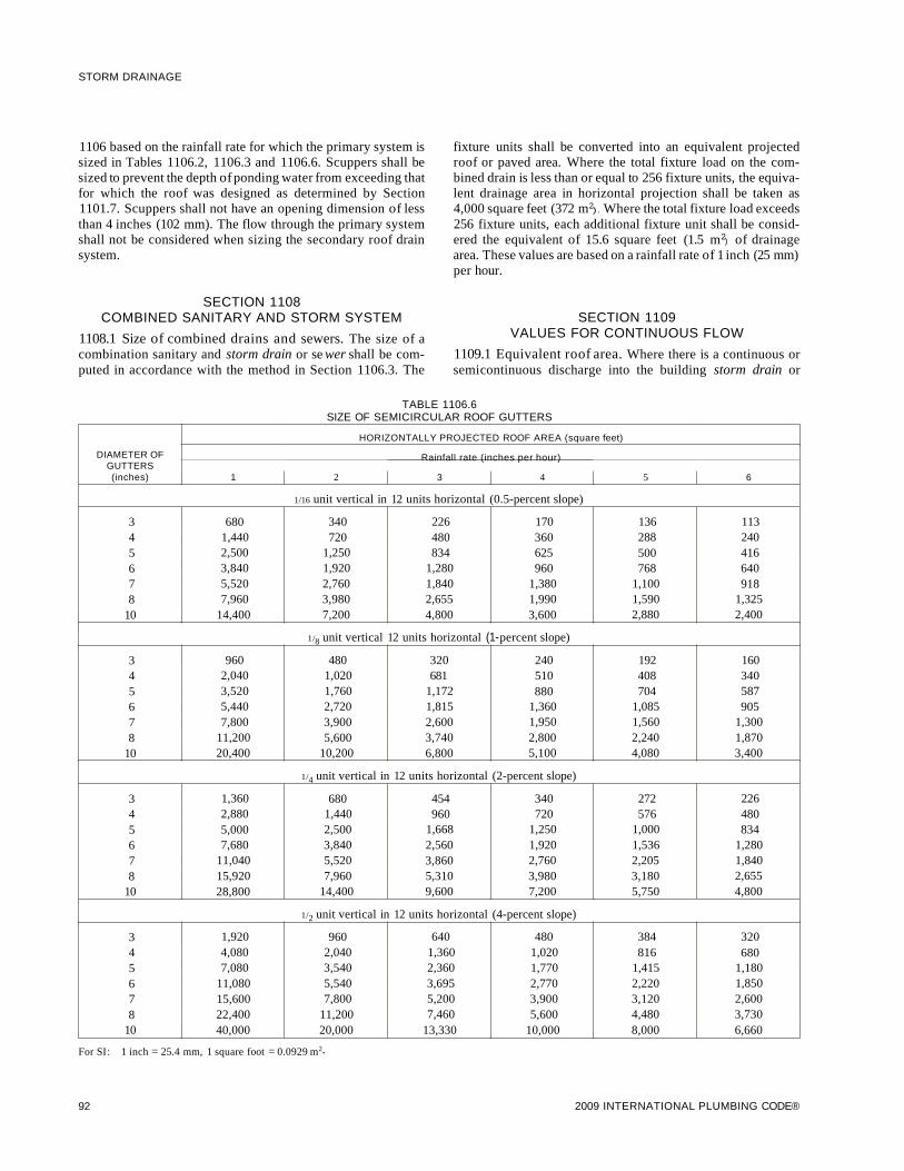
STORM DRAINAGE
1106 based on the rainfall rate for which the primary system issized in Tables 1106.2, 1106.3 and 1106.6. Scuppers shall besized to prevent the depth ofponding water from exceeding thatfor which the roof was designed as determined by Section1101.7. Scuppers shall not have an opening dimension of lessthan 4 inches (102 mm). The flow through the primary systemshall not be considered when sizing the secondary roof drainsystem.
SECTION 1108COMBINED SANITARY AND STORM SYSTEM
1108.1 Size of combined drains and sewers. The size of acombination sanitary and storm drain or se wer shall be computed in accordance with the method in Section 1106.3. The
fixture units shall be converted into an equivalent projectedroof or paved area. Where the total fixture load on the combined drain is less than or equal to 256 fixture units, the equivalent drainage area in horizontal projection shall be taken as4,000 square feet (372 m2). Where the total fixture load exceeds256 fixture units, each additional fixture unit shall be considered the equivalent of 15.6 square feet (1.5 m2) of drainagearea. These values are based on a rainfall rate of 1 inch (25 mm)per hour.
SECTION 1109VALUES FOR CONTINUOUS FLOW
1109.1 Equivalent roof area. Where there is a continuous orsemicontinuous discharge into the building storm drain or
TABLE 1106.6SIZE OF SEMICIRCULAR ROOF GUTTERS
HORIZONTALLY PROJECTED ROOF AREA (square feet)
DIAMETER OF Rainfall rate (inches per hour)GUTTERS(inches) 1 2 3 4 5 6
1/16 unit vertical in 12 units horizontal (0.5-percent slope)
3 680 340 226 170 136 1134 1,440 720 480 360 288 2405 2,500 1,250 834 625 500 4166 3,840 1,920 1,280 960 768 6407 5,520 2,760 1,840 1,380 1,100 9188 7,960 3,980 2,655 1,990 1,590 1,325
10 14,400 7,200 4,800 3,600 2,880 2,400
1/8 unit vertical 12 units horizontal (1-percent slope)
3 960 480 320 240 192 1604 2,040 1,020 681 510 408 3405 3,520 1,760 1,172 880 704 5876 5,440 2,720 1,815 1,360 1,085 9057 7,800 3,900 2,600 1,950 1,560 1,3008 11,200 5,600 3,740 2,800 2,240 1,870
10 20,400 10,200 6,800 5,100 4,080 3,400
1/4 unit vertical in 12 units horizontal (2-percent slope)
3 1,360 680 454 340 272 2264 2,880 1,440 960 720 576 4805 5,000 2,500 1,668 1,250 1,000 8346 7,680 3,840 2,560 1,920 1,536 1,2807 11,040 5,520 3,860 2,760 2,205 1,8408 15,920 7,960 5,310 3,980 3,180 2,655
10 28,800 14,400 9,600 7,200 5,750 4,800
1/2 unit vertical in 12 units horizontal (4-percent slope)
3 1,920 960 640 480 384 3204 4,080 2,040 1,360 1,020 816 6805 7,080 3,540 2,360 1,770 1,415 1,1806 11,080 5,540 3,695 2,770 2,220 1,8507 15,600 7,800 5,200 3,900 3,120 2,6008 22,400 11,200 7,460 5,600 4,480 3,730
10 40,000 20,000 13,330 10,000 8,000 6,660
For SI: 1 inch = 25.4 mm, 1 square foot = 0.0929 m2•
92 2009 INTERNATIONAL PLUMBING CODE®

building storm sewer, such as from a pump, ejector, air conditioning plant or similar device, each gallon per minute (Lim) ofsuch discharge shall be computed as being equivalent to 96square feet (9 m2) of roof area, based on a rainfall rate of 1 inch(25.4 mm) per hour.
SECTION 1110CONTROLLED FLOW ROOF DRAIN SYSTEMS
1110.1 General. The roof of a structure shall be designed forthe storage of water where the storm drainage system is engineered for controlled flow. The controlled flow roof drain system shall be an engineered system in accordance with thissection and the design, submittal, approval, inspection and testing requirements of Section 105.4. The controlled flow systemshall be designed based on the required rainfall rate in accordance with Section 1106.1.
1110.2 Control devices. The control devices shall be installedso that the rate of discharge of water per minute shall notexceed the values for continuous flow as indicated in Section1109.1.
1110.3 Installation. Runoff control shall be by controldevices. Control devices shall be protected by strainers.
1110.4 Minimum number of roof drains. Not less than tworoof drains shall be installed in roof areas 10,000 square feet(929 m2) or less and not less than four roof drains shall beinstalled in roofs over 10,000 square feet (929 m2) in area.
SECTION 1111SUBSOIL DRAINS
1111.1 Subsoil drains. Subsoil drains shall be open-jointed,horizontally split or perforated pipe conforming to one of thestandards listed in Table 1102.5. Such drains shall not be lessthan 4 inches (102 mm) in diameter. Where the building is subject to backwater, the subsoil drain shall be protected by anaccessibly located backwater valve. Subsoil drains shall discharge to a trapped area drain, sump, dry well or approvedlocation above ground. The subsoil sump shall not be required tohave either a gas-tight cover or a vent. The sump and pumpingsystem shall comply with Section 1113.1.
SECTION 1112BUILDING SUBDRAINS
1112.1 Building subdrains. Building subdrains located belowthe public sewer level shall discharge into a sump or receivingtank, the contents of which shall be automatically lifted anddischarged into the drainage system as required for buildingsumps. The sump and pumping equipment shall comply withSection 1113.1.
SECTION 1113SUMPS AND PUMPING SYSTEMS
1113.1 Pumping system. The sump pump, pit and dischargepiping shall conform to Sections 1113.1.1 through 1113.1.4.
2009 INTERNATIONAL PLUMBING CODE®
STORM DRAINAGE
1113.1.1 Pump capacity and head. The sump pump shallbe of a capacity and head appropriate to anticipated userequirements.
1113.1.2 Sump pit. The sump pit shall not be less than 18inches (457 mm) in diameter and 24 inches (610 mm) deep,unless otherwise approved. The pit shall be accessible andlocated such that all drainage flows into the pit by gravity.The sump pit shall be constructed of tile, steel, plastic,cast-iron, concrete or other approved material, with aremovable cover adequate to support anticipated loads inthe area of use. The pit floor shall be solid and provide permanent support for the pump.
1113.1.3 Electrical. Electrical service outlets, whenrequired, shall meet the requirements of NFPA 70.
1113.1.4 Piping. Discharge piping shall meet the requirements of Section 1102.2, 1102.3 or 1102.4 and shall includea gate valve and a full flow check valve. Pipe and fittingsshall be the same size as, or larger than, pump discharge tapping.
Exception: In one- and two-family dwellings, only acheck valve shall be required, located on the dischargepiping from the pump or ejector.
93

94 2009 INTERNATIONAL PLUMBING CODE®
I
CHAPTER 12
SPECIAL PIPING AND STORAGE SYSTEMS
SECTION 1201GENERAL
1201.1 Scope. The provisions of this chapter shall govern thedesign and installation of piping and storage systems for nonflammable medical gas systems and nonmedical oxygen systems. All maintenance and operations of such systems shall bein accordance with the International Fire Code.
SECTION 1202MEDICAL GASES
[F] 1202.1 Nonflammable medical gases. Nonflammablemedical gas systems, inhalation anesthetic systems and vacuum piping systems shall be designed and installed in accordance with NFPA 99C.
Exceptions:
1. This section shall not apply to portable systems or cylinder storage.
2. Vacuum system exhaust terminations shall complywith the International Mechanical Code.
SECTION 1203OXYGEN SYSTEMS
[F] 1203.1 Design and installation. Nonmedical oxygen systems shall be designed and installed in accordance with NFPA50 and NFPA 51.
2009 INTERNATIONAL PLUMBING CODE® 95

96 2009 INTERNATIONAL PLUMBING CODE®

CHAPTER 13
REFERENCED STANDARDS
This chapter lists the standards that are referenced in various sections of this document. The standards are listed herein by the promulgating agency ofthe standard, the standard identification, the effective date and title, and the section or sections of this documentthat reference the standard. The application of the referenced standards shall be as specified in Section 102.8.
ANSIStandardReferenceNumber
Al18-10.99
Z4.3-95
Z21 .22-99(R2003)
Z124.1-95
Z124.2-95
Z124.3-95
Z124.4-96
Z124.6-97
Z124.9-94
AHRIStandardReferenceNumber
1010-02
ASMEStandardReferenceNumber
Al12.1.2-2004
Al12.1.3-2000Reaffirmed 2005
Al12.3.1-2007
Al12.3.4-2000(Reaffirmed 2004)
Al12.4.1-1993 (R2002)
Al12.4.3-1999(Reaffirmed 2004)
Al12.6.1M-1997 (R2002)
Al12.6.2-2000(Reaffirmed 2004)
Al12.6.3-(Reaffirmed 2007)
Al12.6.7-2001(Reaffirmed 2007)
American National Standards Institute25 West 43rd Street, Fourth FloorNew York, NY 10036
Referencedin code
Title section number
Specifications for Load Bearing, Bonded, Waterproof Membranes forThin Set Ceramic Tile and Dimension Stone Installation .417.5.2.5
Minimum Requirements for Nonsewered Waste-disposal Systems 311.1
Relief Valves for Hot Water Supply Systems with Addenda Z21 .22a-2000 (R2003) andZ21.22b-2001 (R2003) 504.2, 504.4
Plastic Bathtub Units .407.1
Plastic Shower Receptors and Shower Stalls .417.1
Plastic Lavatories .416.1,416.2,417.1
Plastic Water Closet Bowls and Tanks .420.1
Plastic Sinks 415.1 , 418.1
Plastic Urinal Fixtures. . . . . . . . . . . . . . . . . . . . . . . . . . . . . . . . . . . . . . . . . . . . . . . . . . . . . . . . . . . . . . . . . . . . . . . . . . . . . . .419.1
Air-Conditioning, Heating, & Refrigeration Institute4100 North Fairfax Drive, Suite 200Arlington, VA 22203
Referencedin code
Title section number
Self-contained, Mechanically Refrigerated Drinking-Water Coolers 410.1
American Society of Mechanical EngineersThree Park AvenueNew York, NY 10016-5990
Referencedin code
Title section number
Air Gaps in Plumbing Systems Table 608.1, 608.13.1
Air Gap Fittings for Use with Plumbing Fixtures, Appliances and Appurtenances Table 608.1 , 608.13.1
Stainless Steel Drainage Systems for Sanitary, DWV, Storm andVacuum Applications Above and Below Ground 412.1, Table 702.1, Table 702.2, Table 702.3,
Table 702.4, 708.2, Table 1102.4, Table 1102.5, 1102.6, Table 1102.7
Macerating Toilet Systems and Related Components 712.4.1
Water Heater Relief Valve Drain Tubes 504.6
Plastic Fittings for Connecting Water Closets to the Sanitary Drainage System 405.4
Floor-affixed Supports for Off-the-floor Plumbing Fixtures for Public Use 405.4.3
Framing-affixed Supports for Off-the-floor Water Closets with Concealed Tanks 405.4.3
2001 Floor and Trench Drains .412.1
Enameled and Epoxy-coated Cast-iron and PVC Plastic Sanitary Floor Sinks 427.1
2009 INTERNATIONAL PLUMBING CODE® 97

REFERENCED STANDARDS
Al12.14.1-2003
Al12.14.3-2000
Al12.14.4-2001(Reaffirmed 2007)
Al12.18.1-2005/CSA B125.1-2005
Al12.18.2-2005/CSA B125.2-2005
Al12.18.3-2002
Al12.18.6-2003
Al12.18.7-1999(Reaffirmed 2004)
Al12.19.1M-2004(Reaffirmed 2004)
Al12.19.2-2003
Al12.19.3M-2000(Reaffirmed 2007)Al12.19.4M-1994(Reaffirmed 2004)
Al12.19.5-2005
Al12.19.6-1995
Al12.19.7M-2006
Al12.19.8M-2007
Al12.19.9M-1991 (R2002)
Al12.19.12-2006
Al12.19.13-2001(Reaffirmed 2007)
Al12.19.15- 2005
Al12.19.19-2006
Al12.21.2M-1983
Al12.36.2M-1991 (R2002)
B1.20.1-1983(R2006)
B16.3-2006
B16.4-2006
B16.9-2003
B16.11-2005
B16.12-1998(Reaffirmed 2006)
B16.15-2006
B16.18-2001(Reaffirmed 2005)
B16.22-2001(Reaffirmed 2005)
B16.23-2002(Reaffirmed 2006)
B16.26-2006
B16.28-1994
B16.29-2001
ASSEStandardReferenceNumber
1001-02
1002-99
98
ASME-continuedBackwater Valves 715.2
Grease Interceptors 1003.3.4
Grease Removal Devices .1 003.3.4
Plumbing Supply Fittings .424.1,424.2,424.3,607.4,608.2
Plumbing Waste Fittings .424.1.2
Performance Requirements for Backflow Protection Devices and Systems in Plumbing Fixture Fittings 424.2,424.6
Flexible Water Connectors 605.6
Deck mounted Bath/Shower Transfer Valves with Integral Backflow Protection 424.8
Enameled Cast Iron Plumbing Fixtures 407.1,410.1,415.1,416.1,418.1
Vitreous China Plumbing Fixtures and Hydraulic Requirements forWater Closets and Urinals 401.2,405.9,408.1,410.1,416.1,418.1,419.1,420.1
Stainless Steel Plumbing Fixtures (Designed for Residential Use) 405.9,415.1,416.1,418.1
Porcelain Enameled Formed Steel Plumbing Fixtures 407.1, 416.1, 418.1
Trim for Water-closet Bowls, Tanks and Urinals .425.4
Hydraulic Performance Requirements for Water Closets and Urinals 419.1, 420.1
Hydromassage Bathtub Appliances .421.1
Suction Fittings for Use in Swimming Pools, Wading Pools, Spas, Hot Tubs 421.4
Nonvitreous Ceramic Plumbing Fixtures with 2002 Supplement. 407.1,408.1,410.1,415.1,416.1,417.1,418.1,420.1
Wall Mounted and Pedestal Mounted, Adjustable, Elevating, Tilting and Pivoting Lavatory, Sink andShampoo Bowl Carrier Systems and Drain Systems .416.4,418.3
Electrohydraulic Water Closets .420.1
Bathtub/Whirlpool Bathtubs with Pressure Sealed Doors 407.4, 421.5
Vitreous China Nonwater Urinals .419.1
Roof Drains 1102.6
Cleanouts 708.2
Pipe Threads, General Purpose (inch) 605.10.3, 605.12.3, 605.14.4,605.16.3,605.18.1,705.2.3,705.4.3,705.9.4, 705.12.1, 705.14.3
Malleable Iron Threaded Fittings Classes 150 and 300 Table 605.5, Table 702.4, Table 1102.7
Gray Iron Threaded Fittings Classes 125 and 250 Table 605.5, Table 702.4, Table 1102.7
Factory-made Wrought Steel Buttwelding Fittings Table 605.5, Table 702.4, Table 1102.7
Forged Fittings, Socket-welding and Threaded Table 605.5, Table 702.4, Table 1102.7
Cast-iron Threaded Drainage Fittings Table 605.5, Table 702.4, Table 1102.7
Cast Bronze Threaded Fittings Table 605.5, Table 702.4, Table 1102.7
Cast Copper Alloy Solder Joint Pressure Fittings Table 605.5, Table 702.4, Table 1102.7
Wrought Copper and Copper Alloy Solder Joint Pressure Fittings Table 605.5, Table 702.4, Table 1102.7
Cast Copper Alloy Solder Joint Drainage Fittings DWV Table 605.5, Table 702.4, Table 1102.7
Cast Copper Alloy Fittings for Flared Copper Tubes Table 605.5, Table 702.4, Table 1102.7
Wrought Steel Buttwelding Short Radius Elbows and Returns Table 605.5, Table 702.4, Table 1102.7
Wrought Copper and Wrought Copper Alloy Solder Joint Drainage Fittings (DWV) Table 605.5, Table 702.4, Table 1102.7
American Society of Sanitary Engineering901 Canterbury Road, Suite AWestlake, OH 44145
Referencedin code
Title section number
Performance Requirements for Atmospheric Type Vacuum Breakers 425.2, Table 608.1,608.13.6,608.16.4.1
Performance Requirements for Antisiphon Fill Valves (Ballcocks) forGravity Water Closet Flush Tanks .425.3.1, Table 608.1
2009 INTERNATIONAL PLUMBING CODE®

REFERENCED STANDARDS
ASSE-continued
1003-01
1004-90
1005-99
1006-89
1007-92
1008-89
1009-90
1010-04
1011-04
1012-02
1013-05
1015-05
1016-96
1017-03
1018-01
1019-04
1020-04
1022-03
1024-04
1035-02
1037-90
1044-01
1047-05
1048-05
1050-02
1051-02
1052-04
1055-97
1056-01
1060-96
1061-06
1062-97
1066-97
1069-05
1070-04
1072-06
1079-2005
5013-98
5015-98
5020-98
5047-98
5048-98
5052-98
5056-98
Performance Requirements for Water Pressure Reducing Valves 604.8
Performance Requirements for Backflow Prevention Requirements for Commercial Dishwashing Machines 409.1
Performance Requirements for Water Heater Drain Valves 501 .3
Performance Requirements for Residential Use Dishwashers .409.1
Performance Requirements for Home Laundry Equipment .406.1, 406.2
Performance Requirements for Household Food Waste Disposer Units 413.1
Performance Requirements for Commercial Food Waste Grinder Units 413.1
Performance Requirements for Water Hammer Arresters 604.9
Performance Requirements for Hose Connection Vacuum Breakers Table 608.1,608.13.6
Performance Requirements for Backflow Preventers with Intermediate Atmospheric Vent Table 608.1,608.13.3,608.16.2
Performance Requirements for Reduced Pressure Principle Backflow Preventers andReduced Pressure Fire Protection Principle Backflow Preventers Table 608.1, 608.13.2, 608.16.2
Performance Requirements for Double Check Backflow Prevention Assemblies andDouble Check Fire Protection Backflow Prevention Assemblies Table 608.1 , 608.13.7
Performance Requirements for Individual Thermostatic, Pressure Balancing andCombination Control Valves for Individual Fixture Fittings 424.3, 424.4, 607.4
Performance Requirements for Temperature Actuated Mixing Valves forHot Water Distribution Systems 501.2, 613.1
Performance Requirements for Trap Seal Primer Valves; Potable Water Supplied 1002.4
Performance Requirements for Vacuum Breaker Wall Hydrants, Freeze Resistant,Automatic Draining Type Table 608.1,608.13.6
Performance Requirements for Pressure Vacuum Breaker Assembly Table 608.1,608.13.5
Performance Requirements for Backflow Preventer for Beverage Dispensing Equipment Table 608.1, 608.16.1, 608.16.10
Performance Requirements for Dual Check Valve Type Backflow Preventers(for Residential Supply Service or Individual Outlets) 605.3.1, Table 608.1
Performance Requirements for Laboratory Faucet Backflow Preventers Table 608.1,608.13.6
Performance Requirements for Pressurized Flushing Devices for Plumbing Fixtures 425.2
Performance Requirements for Trap Seal Primer Devices Drainage Types and Electronic Design Types 1002.4
Performance Requirements for Reduced Pressure Detector Fire ProtectionBackflow Prevention Assemblies Table 608.1,608.13.2
Performance Requirements for Double Check Detector Fire ProtectionBackflow Prevention Assemblies Table 608.1,608.13.7
Performance Requirements for Stack Air Admittance Valves for Sanitary Drainage Systems 917.1
Performance Requirements for Individual and Branch Type Air Admittance Valves forSanitary Drainage Systems-fixture and Branch Devices 917.1
Performance Requirements for Hose Connection Backflow Preventers Table 608.1,608.13.6
Performance Requirements for Chemical Dispensing Systems 608.13.9
Performance Requirements for Spill Resistant Vacuum Breaker Table 608.1,608.13.5,608.13.8
Performance Requirements for Outdoor Enclosures for Backflow Prevention Assemblies 608.14.1
Performance Requirements for Removable and Nonremovable Push Fit Fittings Table 605.5
Performance Requirements for Temperature Actuated, Flow Reduction Valves to Individual Fixture Fittings 424.7
Performance Requirements for Individual Pressure Balancing In-line Valves for Individual Fixture Fittings 604.11
Performance Requirements for Automatic Temperature Control Mixing Valves 424.4
Performance Requirements for Water-temperature Limiting Devices 408.3,416.5,424.5,607.1
Performance Requirements for Barrier Type Floor Drain Trap Seal Protection Devices 1002.4
Dielectric Pipe Unions 605.24.1, 605.24.3
Performance Requirements for Testing Reduced Pressure Principle Backflow Prevention Assembly (RPA) andReduced Pressure Fire Protection Principle Backflow Preventers (RFP) 312.10.2
Performance Requirements for Testing Double Check Valve Backflow Prevention Assembly (DCVA) 312.10.2
Performance Requirements for Testing Pressure Vacuum Breaker Assembly (PVBA) 312.10.2
Performance Requirements for Testing Reduced Pressure Detector Fire ProtectionBackflow Prevention Assemblies (RPDA) 312.10.2
Performance Requirements for Testing Double Check Valve Detector Assembly (DCDA) 312.10.2
Performance Requirements for Testing Hose Connection Backflow Preventers 312.102
Performance Requirements for Testing Spill Resistant Vacuum Breaker 312.10.2
2009 INTERNATIONAL PLUMBING CODE® 99

REFERENCED STANDARDS
ASTMStandardReferenceNumber
ASTM International100 Barr Harbor DriveWest Conshohocken, PA 19428-2959
Title
Referencedin code
section number
A 53/A 53M-06a
A 74-06
A 312/A 312M-06
A 733-03
A 778-01
A 888-07a
B 32-04
B 42-02eOI
B 43-98 (2004)
B 75-02
B 88-03
B 152/B 152M-06a
B 251-02eOI
B 302-02
B 306-02
B 447-07
B 687-99(2005)eOI
B 813-00eOI
B 828-02
C 4-04eOI
C 14-07
C 76-07
C 296-(2004)eOI
C 425-04
C 428-97 (2006)
C 443-05a
C 508-(2004)
C 564-04a
C 700-07
C 1053-00(2005)
C 1173-06
C 1277-06
C 1440-03
C 1460-04
C 1461-06
C 1540-04
C 1563-04
100
Specification for Pipe, Steel, Black and Hot-dipped,Zinc-coated Welded and Seamless Table 605.3 , Table 605.4 , Table 702.1
Specification for Cast-iron Soil Pipe and Fittings Table 702.1, Table 702.2, Table 702.3,Table 702.4, 708.2, 708.7, Table 1102.4, Table 1102.5, Table 1102.7
Specification for Seamless and Welded Austenitic Stainless Steel Pipes Table 605.3, Table 605.4, Table 605.5,605.23.2
Specification for Welded and Seamless Carbon Steel and Austenitic Stainless Steel Pipe Nipples Table 605.8
Specification for Welded Unannealed Austenitic Stainless Steel Tubular Products Table 605.3, Table 605.4, Table 605.5
Specification for Hubless Cast-iron Soil Pipe and Fittings for Sanitary andStorm Drain, Waste, and Vent Piping Application Table 702.1, Table 702.2, Table 702.3,
Table 702.4, 708.7, Table 1102.4, Table 1102.5, Table 1102.7
Specification for Solder Metal. 605.14.3, 605.15.4 , 705.9.3, 705.10.3
Specification for Seamless Copper Pipe, Standard Sizes Table 605.3, Table 605.4, Table 702.1
Specification for Seamless Red Brass Pipe, Standard Sizes Table 605.3, Table 605.4, Table 702.1
Specification for Seamless Copper Tube Table 605.3, Table 605.4, Table 702.1, Table 702.2,Table 702.3, Table 1102.4
Specification for Seamless Copper Water Tube Table 605.3, Table 605.4, Table 702.1,Table 702.2, Table 702.3, Table 1102.4
Specification for Copper Sheet, Strip Plate and Rolled Bar 402.3, ,417.5.2.4,425.3.3,902.2
Specification for General Requirements for Wrought Seamless Copper andCopper-alloy Tube Table 605.3, Table 605.4, Table 702.1,
Table 702.2, Table 702.3, Table 1102.4
Specification for Threadless Copper Pipe, Standard Sizes Table 605.3, Table 605.4, Table 702.1
Specification for Copper Drainage Tube (DWV) Table 702.1, Table 702.2, Table 1102.4
Specification for Welded Copper Tube Table 605.3, Table 605.4
Specification for Brass, Copper and Chromium-plated Pipe Nipples Table 605.8
Specification for Liquid and Paste Fluxes for Soldering of Copper and Copper Alloy Tube 605.14.3,605.15.4,705.9.3,705.10.3
Practice for Making Capillary Joints by Soldering of Copper and Copper All~ Tube and Fittings 605.14.3 ,605.15.4 , 705.9.3 , 705.10.3
Specification for Clay Drain Tile and Perforated Clay Drain Tile Table 702.3, Table 1102.4, Table 1102.5
Specification for Nonreinforced Concrete Sewer, Storm Drain and Culvert Pipe Table 702.3, Table 1102.4
Specification for Reinforced Concrete Culvert, Storm Drain and Sewer Pipe Table 702.3, Table 1102.4
Specification for Asbestos-cement Pressure Pipe Table 605.3
Specification for Compression Joints for Vitrified Clay Pipe and Fittings 705.15,705.19
Specification for Asbestos-cement Nonpressure Sewer Pipe Table 702.2, Table 702.3, Table 702.4, Table 1102.4
Specification for Joints for Concrete Pipe and Manholes, Using Rubber Gaskets 705.6,705.19
Specification for Asbestos-cement Underdrain Pipe Table 1102.5
Specification for Rubber Gaskets for Cast-iron Soil Pipe and Fittings 705.5.2 , 705.5.3 , 705.19, Table 1102.4
Specification for Vitrified Clay Pipe, Extra Strength, Standard Strength, andPerforated Table 702.3, 702.4, Table 1102.4, Table 1102.5
Specification for Borosilicate Glass Pipe and Fittings for Drain, Waste, andVent (DWV) Applications Table 702.1, Table 702.4
Specification for Flexible Transition Couplings for Underground Piping System 705.2.1,705.7.1,705.14.1,705.15,705.16.1,705.19
Specification for Shielded Coupling Joining Hubless Cast-iron Soil Pipe and Fittings 705.5.3
Specification for Thermoplastic Elastomeric (TPE) Gasket Materials for Drain, Waste,andVent (DWV) , Sewer, Sanitary and Storm Plumbing Systems 705.19
Specification for Shielded Transition Couplings for Use with Dissimilar DWV Pipe and Fittings Above Ground 705.19
Specification for Mechanical Couplings Using Thermoplastic Elastomeric (TPE) Gaskets forJoining Drain, Waste and Vent (DWV) Sewer, Sanitary and Storm Plumbing Systems forAbove and Below Ground Use 705.19
Specification for Heavy Duty Shielded Couplings Joining Hubless Cast-iron Soil Pipe and Fittings 705.5.3
Standard Test Method for Gaskets for Use in Connection with Hub and Spigot Cast Iron Soil Pipe andFittings for Sanitary Drain, Waste, Vent and Storm Piping Applications 705.5.2
2009 INTERNATIONAL PLUMBING CODE®

o 1527-99(2005)
o 1785-06
o 1869-95(2005)
02235-04
02239-03
02241-05
o 2282-(2005)9geOl
02464-06
02466-06
02467-06
o 2468-96a
o 2564-04eOl
02609-02
02657-07
02661-06
02665-07
o 2672-96a(2003)
02683-04
o 2729-04eO1
02737-03
02751-05
o 2846/0 2846M-06
o 2855-96(2002)
o 2949-01aeOl
03034-06
03035-03
o 3139-98(2005)
o 3212-96a(2003)eOl
03261-03
o 3311-06a
04068-01
o 4551-96(2001)
F 405-05
F 409-02
F 437-06
F 438-04
F 439-06
F 4411F 441M-02
F 442/F 442M-99(2005)
F 477-07
F 493-04
F 628-06eOl
REFERENCED STANDARDS
ASTM-continued
Specification for Acrylonitrile-Butadiene-Styrene (ABS) Plastic Pipe, Schedules 40 and 80 Table 605.3
Specification for Poly (Vinyl Chloride) (PVC) Plastic Pipe, Schedules 40,80 and 120 Table 605.3
Specification for Rubber Rings for Asbestos-cement Pipe 605.11, 605.24, 705.3, 705.19
Specification for Solvent Cement for Acrylonitrile-Butadiene-Styrene (ABS) PlasticPipe and Fittings 605.10.2 , 705.2.2,705.7.2
Specification for Polyethylene (PE) Plastic Pipe (SIOR-PR) Based on Controlled Inside Diameter Table 605.3
Specification for Poly (Vinyl Chloride) (PVC) Pressure-rated Pipe (SOR-Series) Table 605.3
Specification for Acrylonitrile-Butadiene-Styrene (ABS) Plastic Pipe (SOR-PR) Table 605.3
Specification for Threaded Poly (Vinyl Chloride) (PVC) Plastic Pipe Fittings, Schedule 80 Table 605.5 , Table 1102.7
Specification for Poly (Vinyl Chloride) (PVC) Plastic Pipe Fittings, Schedule 40 Table 605.5, Table 1102.7
Specification for Poly (Vinyl Chloride) (PVC) Plastic Pipe Fittings, Schedule 80 Table 605.5, Table 1102.7
Specification for Acrylonitrile-Butadiene-Styrene (ABS) Plastic Pipe Fittings, Schedule 40 Table 605.5, Table 1102.7
Specification for Solvent Cements for Poly (Vinyl Chloride) (PVC) Plastic Piping Systems 605.21.2,705.8.2,705.14.2
Specification for Plastic Insert Fittings for Polyethylene (PE) Plastic Pipe Table 605.5 , Table 1102.7
Practice for Heat Fusion-joining of Polyolefin Pipe and Fitting 605.19.2,705.16.1
Specification for Acrylonitrile-Butadiene-Styrene (ABS) Schedule 40 Plastic Drain,Waste, and Vent Pipe and Fittings Table 702.1 , Table 702.2,
Table 702.3, Table 702.4, 705.2.2,705.7.2, Table 1102.4, Table 1102.7
Specification for Poly (Vinyl Chloride) (PVC) Plastic Drain, Waste, andVent Pipe and Fittings Table 702.1, Table 702.2, Table 702.3,
Table 702.4, Table 1102.4, Table 1102.7
Specification for Joints for IPS PVC Pipe Using Solvent Cement Table 605.3
Standard Specification for Socket-type Polyethylene fittings forOutside Diameter-controlled Polyethylene Pipe and Tubing Table 605.5
Specification for Poly (Vinyl Chloride) (PVC) Sewer Pipe and Fittings Table 1102.5
Specification for Polyethylene (PE) Plastic Tubing Table 605.3
Specification for Acrylonitrile-Butadiene-Styrene (ABS) Sewer Pipe and Fittings Table 702.3, Table 702.4, Table 1102.7
Specification for Chlorinated Poly (Vinyl Chloride) (CPVC) Plastic Hot andCold Water Distribution Systems Table 605.3, Table 605.4, Table 605.5,605.16.2
Standard Practice for Making Solvent-cemented Joints with Poly (Vinyl Chloride)(PVC) Pipe and Fittings 605.22.2, 705.8.2, 705.14.2
Specification for 3.25-in Outside Diameter Poly (Vinyl Chloride) (PVC) Plastic Drain,Waste, and Vent Pipe and Fittings Table 702.1 , Table 702.2,
Table 702.3, Table 702.4
Specification for Type PSM Poly (Vinyl Chloride) (PVC) Sewer Pipe and Fittings Table 702.3, Table 702.4,Table 1102.7, Table 1102.4
Standard Specification for Polyethylene (PE) Plastic Pipe (OR-PR) Based on Controlled Outside Diameter Table 605.3
Specification for Joints for Plastic Pressure Pipes Using Flexible Elastomeric Seals 605.10.1,605.22.1
Specification for Joints for Drain and Sewer Plastic Pipes Using Flexible Elastomeric Seals 705.2.1,705.8.1,705.14.1,705.16.2
Standard Specification for Butt Heat Fusion Polyethylene (PE) Plastic fittings forPolyethylene (PE) Plastic Pipe and Tubing Table 605.5
Specification for Drain, Waste and Vent (OWV) Plastic Fittings Patterns Table 1102.7Specification for Chlorinated Polyethlene (CPE) Sheeting for Concealed Water-containment Membrane 417.5.2.2
Specification for Poly (Vinyl Chloride) (PVC) Plastic Flexible Concealed Water-containment Membrane 417.5.2.1
Specification for Corrugated Polyethylene (PE) Tubing and Fittings Table 1102.5Specification for Thermoplastic Accessible and Replaceable Plastic Tube and Tubular Fittings 424.1.2 , Table 1102.7
Specification for Threaded Chlorinated Poly (Vinyl Chloride) (CPVC) Plastic Pipe Fittings,Schedule 80 Table 605.5
Specification for Socket-type Chlorinated Poly (Vinyl Chloride) (CPVC) Plastic Pipe Fittings,Schedule 40 Table 605.5
Standard Specification for Chlorinated Poly (Vinyl Chloride) (CPVC) Plastic Pipe Fittings,Schedule 80 Table 605.5
Specification for Chlorinated Poly (Vinyl Chloride) (CPVC) Plastic Pipe,Schedules 40 and 80 Table 605.3 , Table 605.4
Specification for Chlorinated Poly (Vinyl Chloride) (CPVC) Plastic Pipe (SOR-PR) Table 605.3, Table 605.4
Specification for Elastomeric Seals (Gaskets) for Joining Plastic Pipe 605.24,705.19
Specification for Solvent Cements for Chlorinated Poly (Vinyl Chloride) (CPVC) Plastic Pipe and Fittings 605.16.2
Specification for Acrylonitrile-Butadiene-Styrene (ABS) Schedule 40 Plastic Drain, Waste, andVent Pipe with a Cellular Core Table 702.1, Table 702.2, Table 702.3, Table 702.4,
705.2.2,705.7.2, Table 1102.4, Table 1102.7
2009 INTERNATIONAL PLUMBING CODE® 101

REFERENCED STANDARDS
F 656-02
F 714-06a
F 876-06
F 877-07
F 891-04
F 1055-98(2006)
F 1281-07
F 1282-06
F 1412-01eOl
F 1488-03
F 1673-04
F 1807-07
F 1866-07
F 1960-07
F 1974-04
F 1986-01 (2006)
F 2080-05
F 2098-04eO1
F 2159-05
F 2262-03
F 2306/F 2306M-05
F 2389-06
F 2434-05
AWSStandardReferenceNumber
A5.8-04
AWWAStandardReferenceNumber
C104-98
C110-/A21.10-03
C111-00
102
ASTM-continuedSpecification for Primers for Use in Solvent Cement Joints of
Poly (Vinyl Chloride) (PVC) Plastic Pipe and Fittings 605.22.2,705.8.2,705.14.2
Specification for Polyethylene (PE) Plastic Pipe (SDR-PR) Based on Outside Diameter Table 702.3
Specification for Cross-linked Polyethylene (PEX) Tubing Table 605.3, Table 605.4
Specification for Cross-linked Polyethylene (PEX) Plastic Hot andCold Water Distribution Systems Table 605.3, Table 605.4, Table 605.5
Specification for Coextruded Poly (Vinyl Chloride) (PVC) Plastic Pipe with aCellular Core Table 702.1 Table 702.2, Table 702.3,
Table 1102.4, Table 1102.5, Table 1102.7
Standard Specification for Electrofusion Type Polyethylene Fittings forOutside Diameter Controlled Polyethylene Pipe and Tubing Table 605.5
Specification for Cross-linked Polyethylene/Aluminum/Cross-linked Polyethylene (PEX-AL-PEX) Pressure Pipe Table 605.3, Table 605.4, Table 605.5,605.21.1
Specification for Polyethylene/AluminumiPolyethylene (PE-AL-PE) Composite Pressure Pipe ..... Table 605.3, Table 605.4,Table 605.5,605.21.1
Specification for Polyolefin Pipe and Fittings for Corrosive Waste Drainage Table 702.1, Table 702.2,Table 702.4,705.17.1
Specification for Coextruded Composite Pipe Table 702.1, Table 702.2, Table 702.3
Polyyinylidene Fluoride (PVDF) Corrosive Waste Drainage Systems Table 702.1, Table 702.2,Table 702.3, Table 702.4, 705.18.1
Specification for Metal Insert Fittings Utilizing a Copper Crimp Ring forSDR9 Cross-linked Polyethylene (PEX) Tubing Table 605.5
Specification for Poly (Vinyl Chloride) (PVC) Plastic Schedule 40 Drainage andDWV Fabricated Fittings Table 702.4, Table 1102.7
Specification for Cold Expansion Fittings with PEX Reinforcing Rings for use withCross-linked Polyethylene (PEX) Tubing Table 605.5
Specification for Metal Insert Fittings for Polyethylene/Aluminum/Polyethylene andCross-linked Polyethylene/AluminumiCross-linked Polyethylene Composite Pressure Pipe Table 605.5, 605.21.1
Specification for Multilayer Pipe, Type 2, Compression Fittings and Compression Joints forHot and Cold Drinking Water Systems Table 605.3, Table 605.4, Table 605.5
Specifications for Cold-expansion Fittings with Metal Compression-sleeves forCross-linked Polyethylene (PEX) Pipe Table 605.5
Standard specification for Stainless Steel Clamps forSecuring SDR9 Cross-linked Polyethylene (PEX) Tubing to Metal Insert Fittings Table 605.5
Specification for Plastic Insert Fittings Utilizing a Copper Crimp Ring forSDR9 Cross-linked Polyethylene (PEX) Tubing Table 605.5
Specification for Cross-linked Polyethylene/Aluminum/Cross-linkedPolyethylene Tubing 00 Controlled SDR9 Table 605.3, Table 605.4
12" to 60" Annular Corrugated Profile-wall Polyethylene (PE) Pipe andFittings for GraVity Flow Storm Sewer and Subsurface Drainage Applications Table 1102.4, Table 1102.7
Specification for Pressure-rated Polypropylene (PP) Piping Systems Table 605.3, Table 605.4, Table 605.5, 605.20.1
Standard Specification for Metal Insert Fittings Utilizing a Copper Crimp Ring forSDR9 Cross-linked Polyethylene (PEX) Tubing and SDR9 Cross-linked Polyethylene/Aluminum/Cross-linked Polyethylene (PEX AL-PEX) Tubing Table 605.5
American Welding Society550 N.W. Lejeune RoadMiami, FL 33126
Referencedin code
Title section number
Specifications for Filler Metals for Brazing and Braze Welding 605.12.1, 605.14.1, 605.15.1,705.4.1,705.9.1,705.10.1
American Water Works Association6666 West QUincy AvenueDenver, CO 80235
Referencedin code
Title section number
Standard for Cement-mortar Lining for Ductile-iron Pipe and Fittings for Wlter 605.3, 605.5
Standard for Ductile-iron and Gray-iron Fittings, 3 Inches through 48 Inches, for WLter Table 605.5,Table 702.4, Table 1102.7
Standard for Rubber-gasket Joints for Ductile-iron Pressure Pipe and Fittings 605.13
2009 INTERNATIONAL PLUMBING CODE®

Cl15/A21 .15-99
C1511A21.51-02
C153-00/A21.53-00
C510-00
C511-00
C651-99
C652-02
CISPIStandardReferenceNumber
301-04a
310-04
CSAStandardReferenceNumber
B45.1-02
B45.2-02
B45.3-02
B45.4-02
B45.5-02
B45.9-99
B64.1.2-01
B64.2.1-01
B64.2.1.1-01
B64.4.1-01
B64.5-01
B64.5.1-01
B64.6-01
B64.7-94
B64.10/B64.10.1-01
B79-94(2000)
B125-01
B125.3-2005
B137.1-02
B137.2-02
B137.3-02
B137.5-02
B137.6-02
B137.11-02
B181.1-02
B181.2-02
B182.1-02
B182.2-02
REFERENCED STANDARDS
AWWA-continuedStandard for Flanged Ductile-iron Pipe with Ductile-iron or Gray-iron Threaded Flanges Table 605.3, Table 605.4
Standard for Ductile-iron Pipe, Centrifugally Cast for Water Table 605.3, Table 605.4
Standard for Ductile-iron Compact Fittings for Water Service Table 605.5
Double Check Valve Backflow Prevention Assembly Table 608.1, 608.13.7
Reduced-pressure Principle Backflow Prevention Assembly Table 608.1,608.13.2,608.16.2
Disinfecting Water Mains 610.1
Disinfection of Water-storage Facilities 610.1
Cast Iron Soil Pipe Institute5959 Shallowford Road, Suite 419Chattanooga, TN 37421
Referencedin code
Title section number
Specification for Hubless Cast-iron Soil Pipe and Fittings for Sanitary andStorm Drain, Waste and Vent Piping Applications Table 702.1, Table 702.2, Table 702.3,
Table 702.4, 708.7, Table 1102.4, Table 1102.5, Table 1102.7
Specification for Coupling for Use in Connection with Hubless Cast-iron Soil Pipe andFittings for Sanitary and Storm Drain, Waste and Vent Piping Applications 705.5.3
Canadian Standards Association5060 Spectrum Way.Mississauga, Ontario, Canada L4W 5N6
Referencedin code
Title section number
Ceramic Plumbing Fixtures .408.1 , 416.1, 418.1 , 419.1 , 420.1
Enameled Cast-iron Plumbing Fixtures .407.1, 415.1, 416.1, 418.1
Porcelain Enameled Steel Plumbing Fixtures .407.1,416.1,418.1
Stainless-steel Plumbing Fixtures .415.1, 416.1, 418.1, 420.1
Plastic Plumbing Fixtures .407.1, 416.2, 417.1, 419.1, 420.1, 421.1
Macerating Systems and Related Components 712.4.1
Vacuum Breakers, Pressure Type (PVB) Table 608.1 , 608.13.5
Vacuum Breakers, Hose Connection Type (HCVB) with Manual Draining Feature Table 608.1,608.13.6
Vacuum Breakers, Hose Connection Dual Check Type (HCDVB) Table 608.1,608.13.6
Backflow Preventers, Reduced Pressure Principle Type for Fire Sprinklers (RPF) Table 608.1 , 608.13.2
Backflow Preventers, Double Check Type (DCVA) Table 608.1, 608.13.7
Backflow Preventers, Double Check Type for Fire Systems (DCVAF) Table 608.1 608.13.7
Backflow Preventers, Dual Check Valve Type (DuC) 605.3.1, Table 608.1
Vacuum Breakers, Laboratory Faucet Type (LFVB Table 608.1, 608.13.6
Manual for the Selection and Installation of Backflow Prevention Devices/Manual for theMaintenance and Field Testing of Backflow Prevention Devices 312.10.2
Floor, Area and Shower Drains, and Cleanouts for Residential Construction 412.1
Plumbing Fittings .424.4, 424.6, 425.4
Plumbing Fittings .416.5,424.5, 425.3.1, Table 608.1
Polyethylene Pipe, Tubing and Fittings for Cold Water Pressure Services Table 605.3
PVC Injection-moulded Gasketed Fittings for Pressure Applications Table 605.5, Table 1102.7
Rigid Poly (Vinyl Chloride) (PVC) Pipe for Pressure Applications Table 605.3, Table 605.4, Table 605.5,605.22.2, 705.8.2, 705.14.2
Cross-linked Polyethylene (PEX) Tubing Systems for Pressure Applications-with Revisions through September 1992 Table 605.3, Table 605.4, Table 605.5
CPVC Pipe, Tubing and Fittings for Hot and Cold Water Distribution Systems-with Revisions through May 1986 Table 605.3, Table 605.4
Polypropylene (PP-R) Pipe and Fittings for Pressure Applications Table 605.3 , Table 605.4, Table 605.5
ABS Drain, Waste and Vent Pipe and Pipe Fittings Table 702.1 , Table 702.2, Table 702.3,Table 702.4,705.2.2,705.7.2 , 715.2, Table 1102.4, Table 1102.7
PVC Drain, Waste, and Vent Pipe and Pipe Fittings-with Revisions through December 1993 Table 702.1 Table 702.2, 705.8.2, 705.14.2, 715.2
Plastic Drain and Sewer Pipe and Pipe Fittings 705.8.2,705.14.2, Table 1102.4
PVC Sewer Pipe and Fittings (PSM Type) Table 702.3, Table 1102.4, Table 1102.5
2009 INTERNATIONAL PLUMBING CODE® 103

REFERENCED STANDARDS
BI82.4-02
BI82.6-02
BI82.8-02
CAN/CSA-A257.1M-92
CAN/CSA-A257.2M-92
CAN/CSA-A257.3M-92
CAN/CSA-B64.1.1-01
CAN/CSA-B64.2-01
CAN/CSA-B64.2.2-01
CAN/CSA-B64.3-01
CAN/CSA-B64.4-01
CAN/CSA-B64.10-01
CAN/CSA-BI37.9-02
CAN/CSA-BI37.10M-02
CAN/CSA-BI81 .3-02
CAN/CSA-B182.4-02
CAN/CSA-B602-02
ICCStandardReferenceNumber
IBC-09
IEBC-09
IECC-09
IFC-09
IFGC-09
IMC-09
IPSDC-09
IRC-09
ISEAStandardReferenceNumber
Z358.1-98
NFPAStandardReferenceNumber
50-01
51-07
70-08
99C-05
104
CSA-continued
Profile PVC Sewer Pipe and Fittings Table 702.3, Table 1102.4, Table 1102.5
Profile Polyethylene Sewer Pipe and Fittings for Leak-proof Sewer Applications Table 1102.5
Profile Polyethylene Storm Sewer and Drainage Pipe and Fittings Table 1102.5
Circular Concrete Culvert, Storm Drain, Sewer Pipe and Fittings Table 702.3, Table 1102.4
Reinforced Circular Concrete Culvert, Storm Drain, Sewer Pipe and Fittings Table 702.3, Table 1102.4
Joints for Circular Concrete Sewer and Culvert Pipe, Manhole Sections and Fittings Using Rubber Gaskets .....705.6, 705.19
Vacuum Breakers, Atmospheric Type (AVB) 425.2, Table 608.1, 608.13.6
Vacuum Breakers, Hose Connection Type (HCVB) Table 608.1, 608.13.6
Vacuum Breakers, Hose Connection Type (HCVB) with Automatic Draining Feature Table 608.1, 608.13.6
Backflow Preventers, Dual Check Valve Type with Atmospheric Port (DCAP) Table 608.1,608.13.3,608.16.2
Backflow Preventers, Reduced Pressure Principle Type (RP) Table 608.1,608.13.2,608.16.2
Manual for the Selection, Installation, Maintenance and Field Testing of Backflow Prevention Devices 312.10.2
Polyethylene/Aluminum/Polyethylene Composite Pressure Pipe Systems Table 605.3, Table 605.5, 605.21.1
Cross-linked Polyethylene/Aluminum/Polyethylene Composite Pressure Pipe Systems Table 605.3, Table 605.4,Table 605.5,605.21.1
Polyolefin Laboratory Drainage Systems Table 702.1, Table 702.2, Table 702.4, 705.17.1
Profile PVC Sewer Pipe and Fittings Table 702.3, Table 1102.4, Table 1102.5
Mechanical Couplings for Drain, Waste and Vent Pipe and Sewer Pipe 705.2.1,705.5.3,705.6,
705.7.1,705.14.1,705.15,705.16.2,705.19
International Code Council, Inc.500 New Jersey Ave, NW6th FloorWashington, DC 20001
Referencedin code
Title section number
International Building Code® 201.3,305.4,307.1,307.2,307.3,308.2,309.1,310.1, 310.3, 403.1,Table 403.1,404.1,407.3,417.6,502.6,606.5.2, 1106.5
International Existing Building Code 101 .2
International Energy Conservation Code 313.1, 607.2 , 607.2.1
International Fire Code® 201.3, 1201.1
International Fuel Gas Code® 101.2, 201.3 , 502.1
International Mechanical Code® 201.3,307.6,310.1,422.9, 502.1,612.1, 1202.1
International Private Sewage Disposal Code® 701.2
International Residential Code .101.2
International Safety Equipment Association1901 N. Moore Street, Suite 808Arlington, VA 22209
Referencedin code
Title section number
Emergency Eyewash and Shower Equipment 411 .1
National Fire Protection Association1 Batterymarch ParkQUincy, MA 02169-7471
Referencedin code
Title section number
Bulk Oxygen Systems at Consumer Sites 1203.1
Design and Installation of Oxygen-fuel Gas Systems for V\elding, Cutting and Allied Processes 1203.1
National Electric Code 502.1, 504.3,1113.1.3
Gas and Vacuum Systems .1202.1
2009 INTERNATIONAL PLUMBING CODE®
NSFStandardReferenceNumber
3-2007
14-2007
18-2007
42-2007e
44-2004
53-2007
58-2006
61-2007a
62-2004
PDIStandardReferenceNumber
GI0l(2003)
ULStandardReferenceNumber
UL508-99
REFERENCED STANDARDS
NSF International789 Dixboro RoadAnn Arbor, MI 48105
Referencedin code
Title section number
Commercial Warewashing Equipment .409.1
Plastic Piping System Components and Related Materials 303.3, 611.3
Manual Food and Beverage Dispensing Equipment. .426.1Drinking Water Treatment Units-Aesthetic Effects 611.1 , 611.3
Residential Cation Exchange Water Softeners 611 .1, 611 .3
Drinking Water Treatment Units-Health Effects 611.1, 611.3
Reverse Osmosis Drinking Water Treatment Systems 611.2
Drinking Water System Components-Health Effects 410.1,424.1,605.3,605.4,605.5,605.7,611.3,611.3
Drinking Water Distillation Systems 611 .1
Plumbing and Drainage Institute800 Turnpike Street, Suite 300North Andover, MA 01845
Referencedin code
Title section number
Testing and Rating Procedure for Grease Interceptors with Appendix of Sizing and Installation Data 1003.3.4
Underwriters Laboratories, Inc.333 Pfingsten RoadNorthbrook, IL 60062-2096
Referencedin code
Title section number
Industrial Control Equipment with Revision through July 2005 314.2.3
2009 INTERNATIONAL PLUMBING CODE® 105

106 2009 INTERNATIONAL PLUMBING CODE®

APPENDIX A
PLUMBING PERMIT FEE SCHEDULE
The provisions contained in this appendix are not mandatory unless specifically referenced in the adopting ordinance.
Permit Issuance
1. For issuing each permit $ _
2. For issuing each supplemental permit. . . . . . . . . . . . . . . . . . . . . . . . . . . . . . . . . . . . . . . . . . . . . . . . . . . . . . . . . . . . . . _
Unit Fee Schedule
1. For each plumbing fixture or trap or set of fixtures on one trap (including water, drainagepiping and backflow protection thereof) . . . . . . . . . . . . . . . . . . . . . . . . . . . . . . . . . . . . . . . . . . . . . . . . . . . . . . . . . . . _
2. For each building sewer and each trailer park sewer . . . . . . . . . . . . . . . . . . . . . . . . . . . . . . . . . . . . . . . . . . . . . . . . . . . . _
3. Rainwater systems-per drain (inside building) _
4. For each cesspool (where permitted) _
5. For each private sewage disposal system . . . . . . . . . . . . . . . . . . . . . . . . . . . . . . . . . . . . . . . . . . . . . . . . . . . . . . . . . . . . _
6. For each water heater and/or vent .
7. For each industrial waste pretreatment interceptor including its trap and vent,excepting kitchen-type grease interceptors functioning as fixture traps _
8. For installation, alteration or repair ofwater-piping and/or water-treating equipment, each _
9. For repair or alteration ofdrainage or vent piping, each fixture _
10. For each lawn sprinkler system on anyone meter including backflow protection devices therefor _
II. For atmospheric-type vacuum breakers not included in Item 2:
1to 5 .
over 5, each .
12. For each backflow protective device other than atmospheric-type vacuum breakers:
2 inches (51 mm) and smaller _
Over 2 inches (51 mm) _
Other Inspections and Fees
1. Inspections outside ofnormal business hours . . . . . . . . . . . . . . . . . . . . . . . . . . . . . . . . . . . . . . . . . . . . . . . . . . . __per hour(minimum charge two hours)
2. Reinspection fee assessed under provisions ofSection 107.4.3 each
3. Inspections for which no fee is specifically indicated. . . . . . . . . . . . . . . . . . . . . . . . . . . . . . . . . . . . . . . . . . .. per hour(minimum charge one-half hour)
4. Additional plan review required by changes, additions or revisions to approvedplans (minimum charge one-half hour) per hour
2009 INTERNATIONAL PLUMBING CODE® 107

108 2009 INTERNATIONAL PLUMBING CODE®

APPENDIX B
RATES OF RAINFALL FOR VARIOUS CITIES
This appendix is informative and is not part ofthe code.
Rainfall rates, in inches per hour, are based on a storm of I-hour duration and a 100-year return period. The rainfall rates shown inthe appendix are derived from Figure 1106.1.
Springfield 3.4St. Louis 3.2
New Mexico:Albuquerque 2.0Hobbs 3.0Raton 2.5Roswell . . . . . . . . . . . . 2.6SilverCity 1.9
Nebraska:North Platte 3.3Omaha 3.8Scottsbluff 3.1Valentine 3.2
New Jersey:Atlantic City 2.9Newark 3.1Trenton 3.1
New York:Albany 2.5Binghamton 2.3Buffalo 2.3Kingston. . . . . . . . . . . . 2.7New York 3.0Rochester 2.2
North Carolina:Asheville 4.1Charlotte 3.7Greensboro 3.4
Montana:Ekalaka 2.5Havre 1.6Helena 1.5Kalispell 1.2Missoula. . . . . . . . . . . . 1.3
Louisville. . . . . . . . . . . 3.2Middlesboro 3.2Paducah 3.3
Maine:Bangor 2.2Houlton 2.1Portland 2.4
Missouri:Columbia 3.2Kansas City 3.6
Mississippi:Biloxi 4.7Columbus 3.9Corinth 3.6Natchez 4.4Vicksburg 4.1
Michigan:Alpena 2.5Detroit . . . . . . . . . . . . . 2.7Grand Rapids 2.6Lansing 2.8Marquette 2.4Sault Ste. Marie 2.2
Maryland:Baltimore 3.2 Nevada:Hagerstown 2.8 Elko 1.0Oakland 2.7 Ely 1.1Salisbury 3.1 Las Vegas . . . . . . . . . . . 1.4
Reno 1.1Massachusetts:
Boston 2.5 New Hampshire:Pittsfield 2.8 Berlin 2.5Worcester 2.7 Concord 2.5
Keene 2.4
Kentucky:Ashland 3.0Lexington 3.1
Indiana:Evansville 3.2Fort Wayne 2.9Indianapolis 3.1 Minnesota:
Duluth 2.8Grand Marais 2.3Minneapolis 3.1Moorhead 3.2Worthington 3.5
Iowa:Davenport. 3.3Des Moines 3.4Dubuque 3.3Sioux City 3.6
Illinois:Cairo 3.3Chicago 3.0Peoria 3.3Rockford 3.2Springfield 3.3
Florida:Jacksonville 4.3KeyWest 4.3Miami 4.7Pensacola 4.6 Louisiana:Tampa 4.5 Alexandria 4.2
Lake Providence 4.0NewOrleans 4.8Shreveport 3.9
Arkansas:Fort Smith 3.6Little Rock 3.7Texarkana 3.8 Idaho:
Boise 0.9Lewiston 1.1Pocatello 1.2
California:Barstow 1.4Crescent City 1.5Fresno 1.1Los Angeles . . . . . . . . . 2.1Needles 1.6Placerville . . . . . . . . . . 1.5San Fernando 2.3San Francisco. . . . . . . . 1.5Yreka 1.4
Arizona:Flagstaff. . . . . . . . . . . . 2.4Nogales 3.1Phoenix 2.5Yuma 1.6 Hawaii:
Hilo 6.2Honolulu 3.0Wailuku 3.0
Delaware:Georgetown 3.0Wilmington 3.1
Alaska:Fairbanks 1.0 Georgia:Juneau 0.6 Atlanta 3.7
Dalton 3.4Macon 3.9Savannah 4.3Thomasville 4.3
District of Columbia:Washington 3.2
Colorado:Craig 1.5Denver 2.4Durango 1.8Grand Junction 1.7Lamar 3.0Pueblo 2.5
Alabama:Birmingham 3.8Huntsville 3.6Mobile 4.6Montgomery 4.2
Connecticut:Hartford 2.7New Haven 2.8 Kansas:Putnam 2.6 Atwood 3.3
Dodge City 3.3Topeka 3.7Wichita 3.7
2009 INTERNATIONAL PLUMBING CODE® 109

APPENDIX B
Dallas 4.0Del Rio 4.0EIPaso 2.3Houston 4.6Lubbock 3.3Odessa 3.2Pecos 3.0San Antonio 4.2
Wilmington 4.2
North Dakota:Bismarck 2.8Devils Lake 2.9Fargo 3.1Williston. . . . . . . . . . . . 2.6
Pennsylvania:Erie 2.6Harrisburg 2.8Philadelphia 3.1Pittsburgh 2.6Scranton 2.7 Washington:
Omak 1.1Port Angeles 1.1Seattle 1.4Spokane 1.0Yakima l.l
Rhode Island:Block Island 2.75Providence 2.6
Oklahoma:Altus 3.7Boise City 3.3 Vermont:Durant 3.8 B 2 3Okl h C· 3 8 arre .. . . . . . . . . . . .. .a oma Ity....... .
Bratteboro 2.7Burlington 2.1Rutland 2.5
Ohio:Cincinnati. 2.9Cleveland 2.6 Utah:Columbus 2.8 Brigham City 1.2Toledo 2.8 Roosevelt 1.3
Salt Lake City. . . . . . . . 1.3St. George 1.7
Oregon:Baker 0.9Coos Bay 1.5Eugene 1.3 Virginia:Portland 1.2 Bristol 2.7
Charlottesville 2.8Lynchburg 3.2Norfolk 3.4Richmond 3.3
South Carolina:Charleston 4.3 West Virginia:Columbia 4.0 Charleston 2.8Greenville 4.1 M 2 7organtown .
South Dakota:Buffalo 2.8Huron 3.3Pierre 3.1Rapid City 2.9Yankton 3.6
Tennessee:Chattanooga 0.5Knoxville 3.2Memphis 3.7Nashville 3.3
Texas:Abilene. . . . . . . . . . . . . 3.6Amarillo 3.5Brownsville 4.5
Wisconsin:Ashland . . . . . . . . . . . . 2.5Eau Claire 2.9Green Bay 2.6La Crosse 3.1Madison 3.0Milwaukee 3.0
Wyoming:Cheyenne 2.2Fort Bridger . . . . . . . . . 1.3Lander 1.5New Castle 2.5Sheridan. . . . . . . . . . . . 1.7Yellowstone Park ..... 1.4
110 2009 INTERNATIONAL PLUMBING CODE®
APPENDIX C
GRAY WATER RECYCLING SYSTEMS
SECTION C102SYSTEMS FOR FLUSHING WATER
CLOSETS AND URINALS
CI02.1 Collection reservoir. The holding capacity of the reservoir shall be a minimum of twice the volume of waterrequired to meet the daily flushing requirements of the fixturessupplied with gray water, but not less than 50 gallons (189 L).The reservoir shall be sized to limit the retention time of graywater to a maximum of 72 hours.
CI02.2 Disinfection. Gray water shall be disinfected by anapproved method that employs one or more disinfectants suchas chlorine, iodine or ozone that are recommended for use withthe pipes, fittings and equipment by the manufacturer of thepipes, fittings and equipment.
CI02.3 Makeup water. Potable water shall be supplied as asource of makeup water for the gray water system. The potablewater supply shall be protected against backflow in accordancewith Section 608. There shall be a full-open valve located onthe makeup water supply line to the collection reservoir.
CIOI.II.I Required valve. A full-open valve shall beinstalled downstream of the last fixture connection to thegray water discharge pipe before entering the required filter.
CIOI.12 Overflow. The collection reservoir shall be equippedwith an overflow pipe having the same or larger diameter as theinfluent pipe for the gray water. The overflow pipe shall betrapped and shall be indirectly connected to the sanitary drainage system.
CIOI.13 Drain. A drain shall be located at the lowest point ofthe collection reservoir and shall be indirectly connected to thesanitary drainage system. The drain shall be the same diameteras the overflow pipe required in Section C101.12.
CI01.14 Vent required. The reservoir shall be provided with avent sized in accordance with Chapter 9 and based on the diameter of the reservoir influent pipe.
Exception: Bathtubs, showers, lavatories, clothes washersand laundry trays shall not be required to discharge to thesanitary drainage system where such fixtures discharge toan approvedgray water system for flushing of water closetsand urinals or for subsurface landscape irrigation.
The provisions contained in this appendix are not mandatory unless specifically referenced in the adopting ordinance.
Note: Section 301.3 of this code requires all plumbing fixtures that receive water or waste to discharge to the sanitary drainage system of the structure. In order to allow for the utilization ofa gray water system, Section 301.3 should be revised to read as follows:
CIOI.9 Waste water connections. Gray water recycling systems shall receive only the waste discharge of bathtubs, showers, lavatories, clothes washers or laundry trays.
CIOI.IO Collection reservoir. Gray water shall be collected inan approved reservoir constructed of durable, nonabsorbentand corrosion-resistant materials. The reservoir shall be aclosed and gas-tight vessel. Access openings shall be providedto allow inspection and cleaning of the reservoir interior.
CIOI.II Filtration. Gray water entering the reservoir shallpass through an approved filter such as a media, sand ordiatomaceous earth filter.
CIOI.6 Tests. Drain, waste and vent piping for gray water systems shall be tested in accordance with Section 312.
CIOI.7 Inspections. Gray water systems shall be inspected inaccordance with Section 107.
CIOI.8 Potable water connections. Only connections inaccordance with Section C102.3 shall be made between a graywater recycling system and a potable water system.
301.3 Connections to drainage system. All plumbing fixtures, drains, appurtenances and appliances used to receive ordischarge liquid wastes or sewage shall be directly connectedto the sanitary drainage system of the building or premises, inaccordance with the requirements of this code. This sectionshall not be construed to prevent indirect waste systemsrequired by Chapter 8.
SECTION C101GENERAL
C101.1 Scope. The provisions of this appendix shall governthe materials, design, construction and installation of graywater systems for flushing of water closets and urinals and forsubsurface landscape irrigation (see Figures 1 and 2).
C101.2 Definition. The following term shall have the meaningshown herein.
GRAY WATER. Waste discharged from lavatories, bathtubs,showers, clothes washers and laundry trays.
CIOI.3 Permits. Permits shall be required in accordance withSection 106.
CIOI.4 Installation. In addition to the provisions of SectionC101, systems for flushing of water closets and urinals shallcomply with Section C102 and systems for subsurface landscape irrigation shall comply with Section C103. Except asprovided for in Appendix C, all systems shall comply with theprovisions of the International Plumbing Code.
CIOI.5 Materials. Above-ground drain, waste and vent pipingfor gray water systems shall conform to one of the standardslisted in Table 702.1. Gray water underground building drainage and vent pipe shall conform to one of the standards listed inTable 702.2.
2009 INTERNATIONAL PLUMBING CODE® 111
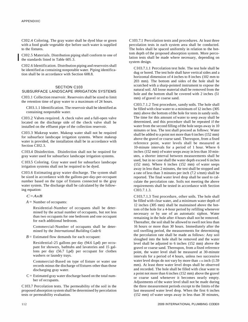
APPENDIXC
CI02.4 Coloring. The gray water shall be dyed blue or greenwith a food grade vegetable dye before such water is suppliedto the fixtures.
I CI02.5 Materials. Distribution piping shall conform to one ofthe standards listed in Table 605 .3.
CI02.6 Identification. Distribution piping and reservoirs shallbe identified as containing nonpotable water. Piping identification shall be in accordance with Section 608.8.
SECTION C103SUBSURFACE LANDSCAPE IRRIGATION SYSTEMS
CI03.1 Collection reservoir. Reservoirs shall be sized to limitthe retention time of gray water to a maximum of 24 hours.
CI03.1.1 Identification. The reservoir shall be identified ascontaining nonpotable water.
CI03.2 Valves required. A check valve and a full-open valvelocated on the discharge side of the check valve shall beinstalled on the effluent pipe of the collection reservoir.
CI03.3 Makeup water. Makeup water shall not be requiredfor subsurface landscape irrigation systems. Where makeupwater is provided, the installation shall be in accordance withSection CI02.3.
CI03.4 Disinfection. Disinfection shall not be required forgray water used for subsurface landscape irrigation systems.
C103.5 Coloring. Gray water used for subsurface landscapeirrigation systems shall not be required to be dyed.
CI03.6 Estimating gray water discharge. The system shallbe sized in accordance with the gallons-per-day-per-occupantnumber based on the type of fixtures connected to the graywater system. The discharge shall be calculated by the following equation:
C=AxB
A = Number of occupants:
Residential-Number of occupants shall be determined by the actual number of occupants, but not lessthan two occupants for one bedroom and one occupantfor each additional bedroom.
Commercial-Number of occupants shall be determined by the International Building Code®.
B = Estimated flow demands for each occupant:
Residential-25 gallons per day (94.6 Lpd) per occupant for showers, bathtubs and lavatories and 15 gallons per day (56.7 Lpd) per occupant for clotheswashers or laundry trays.
Commercial-Based on type of fixture or water userecords minus the discharge of fixtures other than thosedischarging gray water.
C = Estimated gray water discharge based on the total num-ber of occupants.
C103.7 Percolation tests. The permeability of the soil in theproposed absorption system shall be determined by percolationtests or permeability evaluation.
112
C103.7.1 Percolation tests and procedures. At least threepercolation tests in each system area shall be conducted.The holes shall be spaced uniformly in relation to the bottom depth of the proposed absorption system. More percolation tests shall be made where necessary, depending onsystem design.
CI03.7.1.1 Percolation test hole. The test hole shall bedug or bored. The test hole shall have vertical sides and ahorizontal dimension of 4 inches to 8 inches (102 mm to203 mm). The bottom and sides of the hole shall bescratched with a sharp-pointed instrument to expose thenatural soil. All loose material shall be removed from thehole and the bottom shall be covered with 2 inches (51mm) of gravel or coarse sand.
CI03.7.1.2 Test procedure, sandy soils. The hole shallbe filled with clear water to a minimum of 12 inches (305mm) above the bottom of the hole for tests in sandy soils.The time for this amount of water to seep away shall bedetermined, and this procedure shall be repeated if thewater from the second filling of the hole seeps away in 10minutes or less. The test shall proceed as follows: Watershall be added to a point not more than 6 inches (152 mm)above the gravel or coarse sand. Thereupon, from a fixedreference point, water levels shall be measured at10-minute intervals for a period of 1 hour. Where 6inches (152 mm) ofwater seeps away in less than 10 minutes, a shorter interval between measurements shall beused, but in no case shall the water depth exceed 6 inches(152 mm). Where 6 inches (152 mm) of water seepsaway in less than 2 minutes, the test shall be stopped anda rate of less than 3 minutes per inch (7.2 s/mm) shall bereported. The final water level drop shall be used to calculate the percolation rate. Soils not meeting the aboverequirements shall be tested in accordance with SectionCI03.7.1.3.
CI03.7.1.3 Test procedure, other soils. The hole shallbe filled with clear water, and a minimum water depth of12 inches (305 mm) shall be maintained above the bottom of the hole for a 4-hour period by refilling whenevernecessary or by use of an automatic siphon. Waterremaining in the hole after 4 hours shall not be removed.Thereafter, the soil shall be allowed to swell not less than16 hours or more than 30 hours. Immediately after thesoil swelling period, the measurements for determiningthe percolation rate shall be made as follows : Any soilsloughed into the hole shall be removed and the waterlevel shall be adjusted to 6 inches (152 mm) above thegravel or coarse sand. Thereupon, from a fixed referencepoint, the water level shall be measured at 30-minuteintervals for a period of 4 hours, unless two successivewater level drops do not vary by more than 1/16 inch (1.59mm). At least three water level drops shall be observedand recorded. The hole shall be filled with clear water toa point not more than 6 inches (152 mm) above the gravelor coarse sand whenever it becomes nearly empty.Adjustments of the water level shall not be made duringthe three measurement periods except to the limits of thelast measured water level drop. When the first 6 inches(152 mm) of water seeps away in less than 30 minutes,
2009 INTERNATIONAL PLUMBING CODE®

the time interval between measurements shall be 10 minutes and the test run for 1 hour. The water depth shall notexceed 5 inches (127 mm) at any time during the measurement period. The drop that occurs during the finalmeasurement period shall be used in calculating the percolation rate.
CI03.7.1.4 Mechanical test equipment. Mechanicalpercolation test equipment shall be ofan approvedtype.
C103.7.2 Permeability evaluation. Soil shall be evaluatedfor estimated percolation based on structure and texture inaccordance with accepted soil evaluation practices. Boringsshall be made in accordance with Section C103.7.1 for evaluating the soil.
C103.8 Subsurface landscape irrigation site location. Thesurface grade of all soil absorption systems shall be located at apoint lower than the surface grade of any water well or reservoir on the same or adjoining property. Where this is not possible, the site shall be located so surface water drainage from thesite is not directed toward a well or reservoir. The soil absorption system shall be located with a minimum horizontal distance between various elements as indicated in Table C103.8.Private sewage disposal systems in compacted areas, such asparking lots and driveways, are prohibited. Surface water shallbe diverted away from any soil absorption site on the same orneighboring lots.
TABLE C103.8LOCATION OF GRAY WATER SYSTEM
MINIMUM HORIZONTAL DISTANCE
IRRIGATIONHOLDING TANK DISPOSAL FIELD
ELEMENT (feet) (feet)
Buildings 5 2
Property line adjoining5 5
private property
Water wells 50 100
Streams and lakes 50 50
Seepage pits 5 5
Septic tanks 0 5
Water service 5 5
Public water main 10 10
For SI: 1 foot = 304.8 mm.
C103.9 Installation. Absorption systems shall be installed inaccordance with Sections CI03.9.1 through CI03.9.5 to provide landscape irrigation without surfacing of gray water.
CI03.9.1 Absorption area. The total absorption arearequired shall be computed from the estimated daily graywater discharge and the design-loading rate based on thepercolation rate for the site. The required absorption areaequals the estimated gray water discharge divided by thedesign-loading rate from Table CI03.9.1.
2009 INTERNATIONAL PLUMBING CODE®
APPENDIXC
TABLE C 103.9.1DESIGN LOADING RATE
PERCOLATION RATE DESIGN LOADING FACTOR(minutes per inch) (gallons per square foot per day)
oto less than 10 1.2
10 to less than 30 0.8
30 to less than 45 0.72
45 to 60 0.4
For SI: 1 minute per inch = min/25.4 mm,1 gallon per square foot = 40.7 L/m2•
CI03.9.2 Seepage trench excavations. Seepage trenchexcavations shall be a minimum of 1 foot (304 mm) to amaximum of 5 feet (1524 mm) wide. Trench excavationsshall be spaced a minimum of 2 feet (610 mm) apart. Thesoil absorption area of a seepage trench shall be computedby using the bottom of the trench area (width) multiplied bythe length of pipe. Individual seepage trenches shall be amaximum of 100 feet (30 480 mm) in developed length.
CI03.9.3 Seepage bed excavations. Seepage bed excavations shall be a minimum of 5 feet (1524 mm) wide and havemore than one distribution pipe. The absorption area of aseepage bed shall be computed by using the bottom of thetrench area. Distribution piping in a seepage bed shall beuniformly spaced a maximum of 5 feet (1524 mm) and aminimum of 3 feet (914 mm) apart, and a maximum of 3 feet(914 mm) and a minimum of 1foot (305 mm) from the sidewall or headwall.
CI03.9.4 Excavation and construction. The bottom of atrench or bed excavation shall be level. Seepage trenches orbeds shall not be excavated where the soil is so wet that suchmaterial rolled between the hands forms a soil wire. Allsmeared or compacted soil surfaces in the sidewalls or bottom of seepage trench or bed excavations shall be scarifiedto the depth of smearing or compaction and the loose material removed. Where rain falls on an open excavation, thesoil shall be left until sufficiently dry so a soil wire will notform when soil from the excavation bottom is rolledbetween the hands. The bottom area shall then be scarifiedand loose material removed.
CI03.9.5 Aggregate and backfill. A minimum of 6 inchesof aggregate ranging in size from 1/2 to 21/ 2 inches (12.7 mmto 64 mm) shall be laid into the trench below the distributionpiping elevation. The aggregate shall be evenly distributed aminimum of 2 inches (51 mm) over the top of the distribution pipe. The aggregate shall be covered with approvedsynthetic materials or 9 inches (229 mm) of uncompactedmarsh hay or straw. Building paper shall not be used to coverthe aggregate. A minimum of 9 inches (229 mm) of soilbackfill shall be provided above the covering.
CI03.10 Distribution piping. Distribution piping shall be notless than 3 inches (76 mm) in diameter. Materials shall complywith Table C103.1 O. The top of the distribution pipe shall benot less than 8 inches (203 mm) below the original surface. The
113

APPENDIXC
slope of the distribution pipes shall be a minimum of 2 inches(51 mm) and a maximum of 4 inches (102 mm) per 100 feet (30480 mm).
TABLE C103.10DISTRIBUTION PIPE
MATERIAL STANDARD
Polyethylene (PE) plastic pipe ASTM F 405
Polyvinyl chloride (PVC) plastic pipe ASTMD 2729
Polyvinyl chloride (PVC) plastic pipeASTM F 1488
with pipe stiffness of PS 35 and PS 50
CI03.11 Joints. Joints in distribution pipe shall be made inaccordance with Section 705 of this code.
114 2009 INTERNATIONAL PLUMBING CODE®
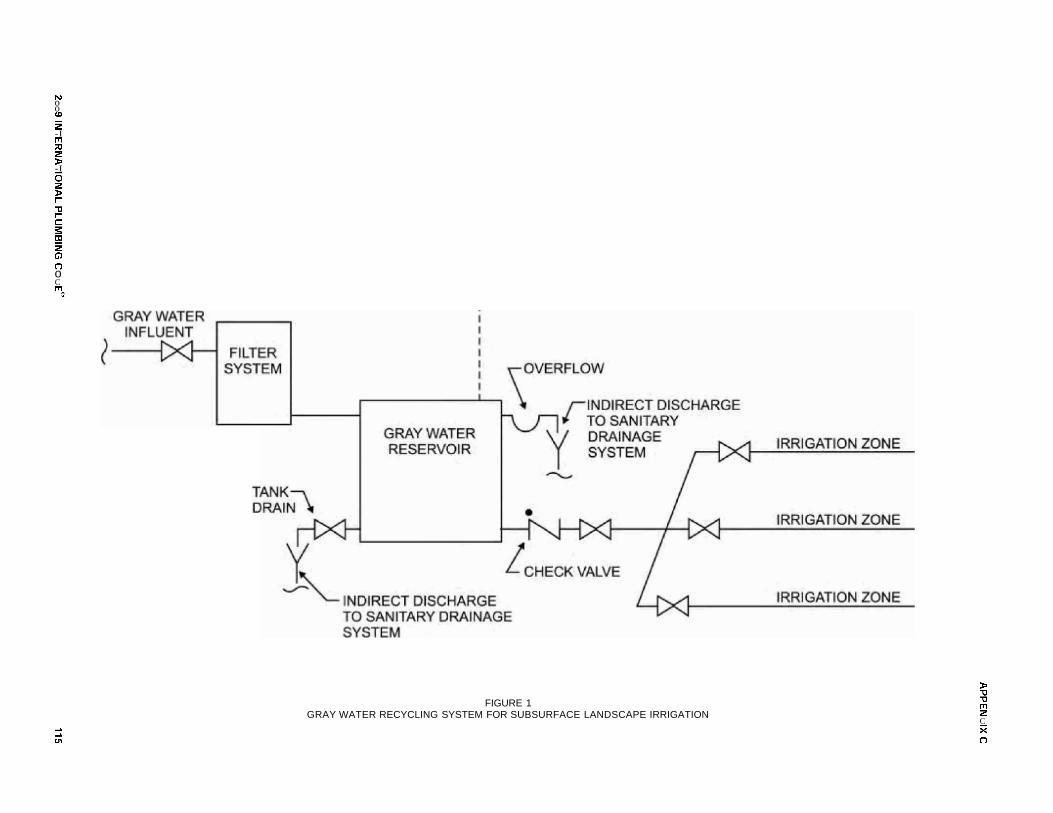
NooCD
:2-Im:::c:2»-Io:2»r-"'tJrCs:to:2G')
(")oCm
®
~
~
CJ'1
FIGURE 1GRAY WATER RECYCLING SYSTEM FOR SUBSURFACE LANDSCAPE IRRIGATION
»"'tJ"'tJm:2CX(")
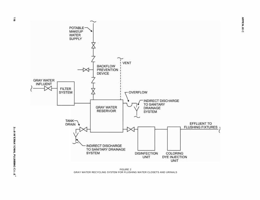
~
~
0')
NooCD
:2-Im:::c:2»-Io:2»r-""CrCs:to:2G)
(")oCm
®
FIGURE 2GRAY WATER RECYCLING SYSTEM FOR FLUSHING WATER CLOSETS AND URINALS
»""C""Cm:2CX(")

APPENDIX D
DEGREE DAY AND DESIGN TEMPERATURES
This appendix is informative and is not part ofthe code.
TABLE D101DEGREE DAY AND DESIGN TEMPERATUREsa FOR CITIES IN THE UNITED STATES
DESIGN TEMPERATURES
HEATING Winter SummerDEGREE DAYS DEGREES NORTH
STATE STATIONb (yearly total) 971/ 2% Dry bulb 21
/ 2% Wet bulb 21/ 2% LATITUDEC
AL Birmingham 2,551 21 94 77 33°30'Huntsville 3,070 16 96 77 34°40'Mobile 1,560 29 93 79 30°40'Montgomery 2,291 25 95 79 32°20'
AK Anchorage 10,864 -18 68 59 61 °10'Fairbanks 14,279 -47 78 62 64°50'
Juneau 9,075 1 70 59 58°20'
Nome 14,171 -27 62 56 64°30'
AZ Flagstaff 7,152 4 82 60 35°10'Phoenix 1,765 34 107 75 33°30'Tuscon 1,800 32 102 71 33°10'
Yuma 974 39 109 78 32°40'
AR Fort Smith 3,292 17 98 79 35°20'Little Rock 3,219 20 96 79 34°40'Texarkana 2,533 23 96 79 33°30'
CA Fresno2,611 30 100 71 36°50'
Long Beach 1,803 43 80 69 33°50'Los Angeles 2,061 43 80 69 34°00'Los Angelesd 1,349 40 89 71 34°00'Oakland 2,870 36 80 64 37°40'
Sacramento 2,502 32 98 71 38°30'
San Diego 1,458 44 80 70 32°40'
San Francisco 3,015 38 77 64 37°40'
San Franciscod 3,001 40 71 62 37°50'
CO Alamosa 8,529 -16 82 61 37°30'Colorado Springs 6,423 2 88 62 38°50'Denver 6,283 1 91 63 39°50'Grand Junction 5,641 7 94 63 39°10'
Pueblo 5,462 0 95 66 38°20'
CT Bridgeport 5,617 9 84 74 41 °10'Hartford 6,235 7 88 75 41 °50'New Haven 5,897 7 84 75 41 °20'
DE Wilmington 4,930 14 89 76 39°40'
DC Washington 4,224 17 91 77 38°50'
FL Daytona879 35 90 79 29°10'
Fort Myers 442 44 92 79 26°40'Jacksonville 1,239 32 94 79 30°30'Key West 108 57 90 79 24°30'Miami 214 47 90 79 25°50'Orlando 766 38 93 78 28°30'Pensacola 1,463 29 93 79 30°30'
Tallahassee 1,485 30 92 78 30°20'
Tampa 683 40 91 79 28°00'
West Palm Beach 253 45 91 79 26°40'
(continued)
2009 INTERNATIONAL PLUMBING CODE® 117

APPENDIX D
TABLE D101-continuedDEGREE DAY AND DESIGN TEMPERATURESa FOR CITIES IN THE UNITED STATES
DESIGN TEMPERATURES
HEATING Winter SummerDEGREE DAYS DEGREES NORTH
STATE STATIONb (yearly total) 971/ 2% Dry bulb 21
/ 2% Wet bulb 21/ 2% LATITUDEc
GA Athens 2,929 22 92 77 34°00'Atlanta 2,961 22 92 76 33°40'Augusta 2,397 23 95 79 33°20'Columbus 2,383 24 93 78 32°30'Macon 2,136 25 93 78 32°40'Rome 3,326 22 93 78 34°20'Savannah 1,819 27 93 79 32°10'
HI Hilo 0 62 83 74 19°40'Honolulu 0 63 86 75 21 °20'
ID Boise 5,809 10 94 66 43°30'Lewiston 5,542 6 93 66 46°20'Pocatello 7,033 -1 91 63 43°00'
IL Chicago (Midway) 6,155 0 91 75 41 °50'Chicago (O 'Hare) 6,639 -4 89 76 42°00'Chicagod 5,882 2 91 77 41 °50'Moline 6,408 -4 91 77 41 °30'Peoria 6,025 -4 89 76 40°40'Rockford 6,830 -4 89 76 42°10'Springfield 5,429 2 92 77 39°50'
IN Evansville 4,435 9 93 78 38°00'Fort Wayne 6,205 1 89 75 41 °00'Indianapolis 5,699 2 90 76 39°40'South Bend 6,439 1 89 75 41 °40'
IA Burlington 6,114 -3 91 77 40°50'Des Moines 6,588 -5 91 77 41 °30'Dubuque 7,376 -7 88 75 42°20'Sioux City 6,951 -7 92 77 42°20'Waterloo 7,320 -10 89 77 42°30'
KS Dodge City 4,986 5 97 73 37°50'Goodland 6,141 0 96 70 39°20'Topeka 5,182 4 96 78 39°00'Wichita 4,620 7 98 76 37°40'
KY Covington 5,265 6 90 75 39°00'Lexington 4,683 8 91 76 38°00'Louisville 4,660 10 93 77 38°10'
LA Alexandria 1,921 27 94 79 31 °20'Baton Rouge 1,560 29 93 80 30°30'Lake Charles 1,459 31 93 79 30°10'New Orleans 1,385 33 92 80 30°00'Shreveport 2,184 25 96 79 32°30'
ME Caribou 9,767 -13 81 69 46°50'Portland 7,511 -1 84 72 43°40'
MD Baltimore 4,654 13 91 77 39°10'Baltimored 4,111 17 89 78 39°20'Frederick 5,087 12 91 77 39°20'
(continued)
118 2009 INTERNATIONAL PLUMBING CODE®

TABLE D101-continuedDEGREE DAY AND DESIGN TEMPERATURESa FOR CITIES IN THE UNITED STATES
APPENDIX D
DESIGN TEMPERATURES
HEATING Winter SummerDEGREE DAYS DEGREES NORTH
STATE STATIONb (yearly total) 971/ 2% Dry bulb 21
/ 2% Wet bulb 21/ 2% LATITUDEc
Boston 5,634 9 88 74 42°20'MA Pittsfield 7,578 -3 84 72 42°30'
Worcester 6,969 4 84 72 42°20'
Alpena 8,506 -6 85 72 45°00'Detroit (City) 6,232 6 88 74 42°20'Escanabad 8,481 -7 83 71 45°40'Flint 7,377 1 87 74 43°00'
MI Grand Rapids 6,894 5 88 74 42°50'Lansing 6,909 1 87 74 42°50'Marquetted 8,393 -8 81 70 46°30'Muskegon 6,696 6 84 73 43°10'Sault Ste. Marie 9,048 -8 81 70 46°30'
Duluth 10,000 -16 82 70 46°50'MN Minneapolis 8,382 -12 89 5 44°50'
Rochester 8,295 -12 87 75 44°00'
Jackson 2,239 25 95 78 32°20'MS Meridian 2,289 23 95 79 32°20'
Vicksburgd 2,041 26 95 80 32°20'
Columbia 5,046 4 94 77 39°00'Kansas City 4,711 6 96 77 39°10'
MOSt. Joseph 5,484 2 93 79 39°50'St. Louis 4,900 6 94 77 38°50'St. Louisd 4,484 8 94 77 38°40'Springfield 4,900 9 93 77 37°10'
Billings 7,049 -10 91 66 45°50'
MTGreat Falls 7,750 -15 88 62 47°30'Helena 8,129 -16 88 62 46°40'Missoula 8,125 -6 88 63 46°50'
Grand Island 6,530 -3 94 74 41 °00'Lincolnd 5,864 -2 95 77 40°50'
NENorfolk 6,979 -4 93 77 42°00'North Platte 6,684 -4 94 72 41 °10'Omaha 6,612 -3 91 77 41 °20'Scottsbluff 6,673 -3 92 68 41 °50'
Elko 7,433 -2 92 62 40°50'Ely 7,733 -4 87 59 39°10'
NV Las Vegas 2,709 28 106 70 36°10'Reno 6,332 10 92 62 39°30'Winnemucca 6,761 3 94 62 40°50'
NH Concord 7,383 -3 87 73 43°10'
Atlantic City 4,812 13 89 77 39°30'NJ Newark 4,589 14 91 76 40°40'
Trentond 4,980 14 88 76 40°10'
Albuquerque 4,348 16 94 65 35°00'
NMRaton 6,228 1 89 64 36°50'Roswell 3,793 18 98 70 33°20'Silver City 3,705 10 94 64 32°40'
(continued)
2009 INTERNATIONAL PLUMBING CODE® 119

APPENDIX D
TABLE D101-continuedDEGREE DAY AND DESIGN TEMPERATURESa FOR CITIES IN THE UNITED STATES
DESIGN TEMPERATURES
HEATING Winter SummerDEGREE DAYS DEGREES NORTH
STATE STATIONb (yearly total) 971/ 2% Dry bulb 21
/ 2% Wet bulb 21/ 2% LATITUDEc
NY Albany 6,875 -1 88 74 42°50'Albanyd 6,201 1 88 74 42°50'Binghamton 7,286 1 83 72 42°10'Buffalo 7,062 6 85 73 43°00'NY (Central Park)d 4,871 15 89 75 40°50'NY (Kennedy) 5,219 15 87 75 40°40'NY(LaGuardia) 4,811 15 89 75 40°50'Rochester 6,748 5 88 73 43°10'Schenectadyd 6,650 1 87 74 42°50'Syracuse 6,756 2 87 73 43°10'
NC Charlotte 3,181 22 93 76 35°10'Greensboro 3,805 18 91 76 36°10'Raleigh 3,393 20 92 77 35°50'Winston-Salem 3,595 20 91 75 36°10'
NO Bismarck 8,851 -19 91 71 46°50'Devils Laked 9,901 -21 88 71 48°10'Fargo 9,226 -18 89 74 46°50'Williston 9,243 -21 88 70 48°10'
OH Akron-Canton 6,037 6 86 73 41 °00'Cincinnatid 4,410 6 90 75 39°10'Cleveland 6,351 5 88 74 41 °20'Columbus 5,660 5 90 75 40°00'Dayton 5,622 4 89 75 39°50'Mansfield 6,403 5 87 74 40°50'Sanduskyd 5,796 6 91 74 41 °30'Toledo 6,494 1 88 75 41 °40'Youngstown 6,417 4 86 73 41 °20'
OK Oklahoma City 3,725 13 97 77 35°20'Tulsa 3,860 13 98 78 36°10'
OR Eugene 4,726 22 89 67 44°10'Medford 5,008 23 94 68 42°20'Portland 4,635 23 85 67 45°40'Portlandd 4,109 24 86 67 45°30'Salem 4,754 23 88 68 45°00'
PA Allentown 5,810 9 88 75 40°40'Erie 6,451 9 85 74 42°10'Harrisburg 5,251 11 91 76 40°10'Philadelphia 5,144 14 90 76 39°50'Pittsburgh 5,987 5 86 73 40°30'Pittsburghd 5,053 7 88 73 40°30'Readingd 4,945 13 89 75 40°20'Scranton 6,254 5 87 73 41 °20'Williamsport 5,934 7 89 74 41 °10'
RI Providence 5,954 9 86 74 41 °40'
SC Charleston 2,033 27 91 80 32°50'Charlestond 1,794 28 92 80 32°50'Columbia 2,484 24 95 78 34°00'
(continued)
120 2009 INTERNATIONAL PLUMBING CODE®
TABLE D101-continuedDEGREE DAY AND DESIGN TEMPERATURESa FOR CITIES IN THE UNITED STATES
APPENDIX D
DESIGN TEMPERATURES
HEATING Winter SummerDEGREE DAYS DEGREES NORTH
STATE STATIONb (yearly total) 971/ 2% Dry bulb 21
/ 2% Wet bulb 21/ 2% LATITUDEc
SD Huron 8,223 -14 93 75 44°30'Rapid City 7,345 -7 92 69 44°00'Sioux Falls 7,839 -11 91 75 43°40'
TN Bristol 4,143 14 89 75 36°30'Chattanooga 3,254 18 93 77 35°00'Knoxville 3,494 19 92 76 35°50'Memphis 3,232 18 95 79 35°00'Nashville 3,578 14 94 77 36°10'
TX Abilene 2,624 20 99 74 32°30'Austin 1,711 28 98 77 30°20'Dallas 2,363 22 100 78 32°50'El Paso 2,700 24 98 68 31 °50'Houston 1,396 32 94 79 29°40'Midland 2,591 21 98 72 32°00'San Angelo 2,255 22 99 74 31 °20'San Antonio 1,546 30 97 76 29°30'Waco 2,030 26 99 78 31 °40'Wichita Falls 2,832 18 101 76 34°00'
UT Salt Lake City 6,052 8 95 65 40°50'
VT Burlington 8,269 -7 85 72 44°30'
VA Lynchburg 4,166 16 90 76 37°20'Norfolk 3,421 22 91 78 36°50'Richmond 3,865 17 92 78 37°30'Roanoke 4,150 16 91 74 37°20'
WA Olympia 5,236 22 83 66 47°00'Seattle-Tacoma 5,145 26 80 64 47°30'Seattled 4,424 27 82 67 47°40'Spokane 6,655 2 90 64 47°40'
WV Charleston 4,476 11 90 75 38°20'Elkins 5,675 6 84 72 38°50'Huntington 4,446 10 91 77 38°20'Parkersburgd 4,754 11 90 76 39°20'
WI Green Bay 8,029 -9 85 74 44°30'La Crosse 7,589 -9 88 75 43°50'Madison 7,863 -7 88 75 43°10'Milwaukee 7,635 -4 87 74 43°00'
WY Casper 7,410 -5 90 61 42°50'Cheyenne 7,381 -1 86 62 41 °10'Lander 7,870 -11 88 63 42°50'Sheridan 7,680 -8 91 65 44°50'
a. All data were extracted from the 1985 ASHRAE Handbook, Fundamentals Volume.b. Design data developed from airport temperature observations unless noted.c. Latitude is given to the nearest 10 minutes. For example, the latitude for Miami, Florida, is given as 25°50', or 25 degrees 50 minutes.d. Design data developed from office locations within an urban area, not from airport temperature obserwtions.
2009 INTERNATIONAL PLUMBING CODE® 121

122 2009 INTERNATIONAL PLUMBING CODE®

APPENDIX E
SIZING OF WATER PIPING SYSTEM
The provisions contained in this appendix are not mandatory unless specifically referenced in the adopting ordinance.
SECTION E101GENERAL
EIOl.l Scope.
EIOl.l.l This appendix outlines two procedures for sizinga water piping system (see Sections EI03.3 and E201.1).The design procedures are based on the minimum staticpressure available from the supply source, the head changesin the system caused by friction and elevation, and the ratesof flow necessary for operation of various fixtures.
EIOl.l.2 Because of the variable conditions encountered inhydraulic design, it is impractical to specify definite anddetailed rules for sizing of the water piping system. Accordingly, other sizing or design methods conforming to goodengineering practice standards are acceptable alternatives tothose presented herein.
SECTION E102INFORMATION REQUIRED
EI02.1 Preliminary. Obtain the necessary informationregarding the minimum daily static service pressure in the areawhere the building is to be located. If the building supply is tobe metered, obtain information regarding friction loss relativeto the rate of flow for meters in the range of sizes likely to beused. Friction loss data can be obtained from most manufacturers of water meters.
EI02.2 Demand load.
EI02.2.1 Estimate the supply demand of the building mainand the principal branches and risers of the system by totaling the corresponding demand from the applicable part ofTable EI03.3(3).
EI02.2.2 Estimate continuous supply demands in gallonsper minute (Lim) for lawn sprinklers, air conditioners, etc.,and add the sum to the total demand for fixtures. The resultis the estimated supply demand for the building supply.
SECTION E103SELECTION OF PIPE SIZE
EI03.1 General. Decide from Table 604.3 what is the desirable minimum residual pressure that should be maintained atthe highest fixture in the supply system. If the highest group offixtures contains flush valves, the pressure for the group shouldnot be less than 15 pounds per square inch (psi) (103.4 kPa)flowing. For flush tank supplies, the available pressure shouldnot be less than 8 psi (55.2 kPa) flowing, except blowout actionfixtures must not be less than 25 psi (172.4 kPa) flowing.
EI03.2 Pipe sizing.
EI03.2.1 Pipe sizes can be selected according to the following procedure or by other design methods conforming to
2009 INTERNATIONAL PLUMBING CODE®
acceptable engineering practice and approved by theadministrative authority. The sizes selected must not be lessthan the minimum required by this code.
EI03.2.2 Water pipe sizing procedures are based on a system of pressure requirements and losses, the sum of whichmust not exceed the minimum pressure available at the supply source. These pressures are as follows:
1. Pressure required at fixture to produce required flow.See Sections 604.3 and 604.5.
2. Static pressure loss or gain (due to head) is computedat 0.433 psi per foot (9.8 kPa/m) ofelevation change.
Example: Assume that the highest fixture supplyoutlet is 20 feet (6096 mm) above or below the supply source. This produces a static pressure differential of20 feet by 0.433 psilfoot (2096 mm by 9.8kPa/m) and an 8.66 psi (59.8 kPa) loss.
3. Loss through water meter. The friction or pressureloss can be obtained from meter manufacturers.
4. Loss through taps in water main.
5. Losses through special devices such as filters, softeners, backflow prevention devices and pressure regulators. These values must be obtained from themanufacturers.
6. Loss through valves and fittings. Losses for theseitems are calculated by converting to equivalentlength of piping and adding to the total pipe length.
7. Loss due to pipe friction can be calculated when thepipe size, the pipe length and the flow through thepipe are known. With these three items, the frictionloss can be determined. For piping flow charts notincluded, use manufacturers' tables and velocity recommendations.
Note: For the purposes of all examples, the followingmetric conversions are applicable:
1 cubic foot per minute = 0.4719 Lis
1 square foot = 0.0929 m2
1 degree = 0.0175 rad
1 pound per square inch = 6.895 kPa
1 inch = 25.4 mm
1 foot = 304.8 mm
1 gallon per minute = 3.785 Lim
EI03.3 Segmented loss method. The size of water servicemains, branch mains and risers by the segmented loss method,must be determined according to water supply demand [gpm(Lim)], available water pressure [psi (kPa)] and friction losscaused by the water meter and developed length of pipe [feet
123

APPENDIX E
(m)] , including equivalent length of fittings. This design procedure is based on the following parameters:
• Calculates the friction loss through each length of the pipe.• Based on a system of pressure losses, the sum of which
must not exceed the minimum pressure available at thestreet main or other source of supply.
• Pipe sizing based on estimated peak demand, total pressurelosses caused by difference in elevation, equipment, developed length and pressure required at most remote fixture,loss through taps in water main, losses through fittings, filters, backflow prevention devices, valves and pipe friction.
Because of the variable conditions encountered in hydraulicdesign, it is impractical to specify definite and detailed rules forsizing of the water piping system. Current sizing methods donot address the differences in the probability of use and flowcharacteristics of fixtures between types ofoccupancies. Creating an exact model of predicting the demand for a building isimpossible and final studies assessing the impact of water conservation on demand are not yet complete. The following stepsare necessary for the segmented loss method.
1. Preliminary. Obtain the necessary information regarding the minimum daily static service pressure in the areawhere the building is to be located. If the building supplyis to be metered, obtain information regarding frictionloss relative to the rate of flow for meters in the range ofsizes to be used. Friction loss data can be obtained frommanufacturers ofwater meters. It is essential that enoughpressure be available to overcome all system lossescaused by friction and elevation so that plumbing fixtures operate properly. Section 604.6 requires the waterdistribution system to be designed for the minimum pressure available taking into consideration pressure fluctuations. The lowest pressure must be selected to guaranteea continuous, adequate supply ofwater. The lowest pressure in the public main usually occurs in the summerbecause of lawn sprinkling and supplying water forair-conditioning cooling towers. Future demands placedon the public main as a result of large growth or expansion should also be considered. The available pressurewill decrease as additional loads are placed on the publicsystem.
2. Demand load. Estimate the supply demand of the building main and the principal branches and risers of the system by totaling the corresponding demand from theapplicable part of Table E103.3(3). When estimatingpeak demand sizing methods typically use water supplyfixture units (w.s.f.u.) [see Table E103.3(2)]. Thisnumerical factor measures the load-producing effect of asingle plumbing fixture of a given kind. The use of suchfixture units can be applied to a single basic probabilitycurve (or table), found in the various sizing methods[Table E103.3(3)]. The fixture units are then convertedinto gallons per minute (Lim) flow rate for estimatingdemand.
2.1. Estimate continuous supply demand in gallonsper minute (Lim) for lawn sprinklers, air conditioners, etc., and add the sum to the total demandfor fixtures. The result is the estimated supply
124
demand for the building supply. Fixture unitscannot be applied to constant use fixtures such ashose bibbs, lawn sprinklers and air conditioners.These types of fixtures must be assigned the gallon per minute (Lim) value.
3. Selection of pipe size. This water pipe sizing procedureis based on a system of pressure requirements and losses,the sum of which must not exceed the minimum pressureavailable at the supply source. These pressures are as follows:
3.1. Pressure required at the fixture to producerequired flow. See Section 604.3 and Section604.5.
3.2. Static pressure loss or gain (because of head) iscomputed at 0.433 psi per foot (9.8 kPa/m) ofelevation change.
3.3. Loss through a water meter. The friction or pressure loss can be obtained from the manufacturer.
3.4. Loss through taps in water main [see TableE103.3(4)].
3.5. Losses through special devices such as filters,softeners, backflow prevention devices and pressure regulators. These values must be obtainedfrom the manufacturers.
3.6. Loss through valves and fittings [see TablesE103.3(5) and E103.3(6)]. Losses for these itemsare calculated by converting to equivalent lengthof piping and adding to the total pipe length.
3.7. Loss caused by pipe friction can be calculatedwhen the pipe size, the pipe length and the flowthrough the pipe are known. With these threeitems, the friction loss can be determined usingFigures E103.3(2) through E103.3(7). Whenusing charts, use pipe inside diameters. For piping flow charts not included, use manufacturers 'tables and velocity recommendations. Beforeattempting to size any water supply system, it isnecessary to gather preliminary informationwhich includes available pressure, piping material, select design velocity, elevation differencesand developedlength to most remote fixture. Thewater supply system is divided into sections atmajor changes in elevation or where brancheslead to fixture groups. The peak demand must bedetermined in each part of the hot and cold watersupply system which includes the correspondingwater supply fixture unit and conversion to gallons per minute (Lim) flow rate to be expectedthrough each section. Sizing methods require thedetermination of the "most hydraulicallyremote" fixture to compute the pressure losscaused by pipe and fittings. The hydraulicallyremote fixture represents the most downstreamfixture along the circuit of piping requiring themost available pressure to operate properly. Consideration must be given to all pressure demandsand losses, such as friction caused by pipe, fit-
2009 INTERNATIONAL PLUMBING CODE®

tings and equipment, elevation and the residualpressure required by Table 604.3. The two mostcommon and frequent complaints about thewater supply system operation are lack of adequate pressure and noise.
Problem: What size Type L copper water pipe, service and distribution will be required to serve a two-story factory buildinghaving on each floor, back-to-back, two toilet rooms eachequipped with hot and cold water? The highest fixture is 21 feet(6401 mm) above the street main, which is tapped with a 2-inch(51 mm) corporation cock at which point the minimum pressure is 55 psi (379.2 kPa). In the building basement, a 2-inch(51 mm) meter with a maximum pressure drop of 11 psi (75.8kPa) and 3-inch (76 mm) reduced pressure principle backflowpreventer with a maximum pressure drop of 9 psi (621 kPa) areto be installed. The system is shown by Figure E103.3(1). To bedetermined are the pipe sizes for the service main and the coldand hot water distribution pipes.
Solution: A tabular arrangement such as shown in TableE103.3(1) should first be constructed. The steps to be followed are indicated by the tabular arrangement itself as theyare in sequence, columns 1 through 10 and lines A throughL.
Step 1
Columns 1 and 2: Divide the system into sections breakingat major changes in elevation or where branches lead to fixture groups. After point B [see Figure E103.3(1)], separateconsideration will be given to the hot and cold water piping.Enter the sections to be considered in the service and coldwater piping in Column 1 of the tabular arrangement. Column 1 of Table E103.3(1) provides a line-by-line recommended tabular arrangement for use in solving pipe sizing.
The objective in designing the water supply system is toensure an adequate water supply and pressure to all fixturesand equipment. Column 2 provides the pounds per squareinch (psi) to be considered separately from the minimumpressure available at the main. Losses to take into consideration are the following: the differences in elevationsbetween the water supply source and the highest water supply outlet, meter pressure losses, the tap in main loss, specialfixture devices such as water softeners and backflow prevention devices and the pressure required at the most remotefixture outlet. The difference in elevation can result in anincrease or decrease in available pressure at the main.Where the water supply outlet is located above the source,this results in a loss in the available pressure and is subtracted from the pressure at the water source. Where thehighest water supply outlet is located below the water supply source, there will be an increase in pressure that is addedto the available pressure of the water source.
Column 3: According to Table E103.3(3), determine thegpm (Lim) of flow to be expected in each section of the system. These flows range from 28.6 to 108 gpm. Load valuesfor fixtures must be determined as water supply fixture unitsand then converted to a gallon-per-minute (gpm) rating todetermine peak demand. When calculating peak demands,the water supply fixture units are added and then convertedto the gallon-per-minute rating. For continuous flow fix-
2009 INTERNATIONAL PLUMBING CODE®
APPENDIX E
tures such as hose bibbs and lawn sprinkler systems, add thegallon-per-minute demand to the intermittent demand offixtures. For example, a total of 120 water supply fixtureunits is converted to a demand of 48 gallons per minute. Twohose bibbs x 5 gpm demand = 10 gpm. Total gpm rating =48.0 gpm + 10 gpm = 58.0 gpm demand.
Step 2
Line A: Enter the minimum pressure available at the mainsource of supply in Column 2. This is 55 psi (379.2 kPa).The local water authorities generally keep records of pressures at different times of day and year. The available pressure can also be checked from nearby buildings or from firedepartment hydrant checks.
Line B: Determine from Table 604.3 the highest pressurerequired for the fixtures on the system, which is 15 psi(103.4 kPa) , to operate a flushometer valve. The mostremote fixture outlet is necessary to compute the pressureloss caused by pipe and fittings, and represents the mostdownstream fixture along the circuit of piping requiring theavailable pressure to operate properly as indicated by Table604.3.
Line C: Determine the pressure loss for the meter size givenor assumed. The total water flow from the main through theservice as determined in Step 1 will serve to aid in the meterselected. There are three common types of water meters; thepressure losses are determined by the American WaterWorks Association Standards for displacement type, compound type and turbine type. The maximum pressure loss ofsuch devices takes into consideration the meter size, safeoperating capacity (gpm) and maximum rates for continuous operations (gpm). Typically, equipment imparts greaterpressure losses than piping.
Line D: Select from Table E103.3(4) and enter the pressureloss for the tap size given or assumed. The loss of pressurethrough taps and tees in pounds per square inch (psi) arebased on the total gallon-per-minute flow rate and size of thetap.
Line E: Determine the difference in elevation between themain and source ofsupply and the highest fixture on the system. Multiply this figure, expressed in feet, by 0.43 psi (2.9kPa). Enter the resulting psi loss on Line E. The differencein elevation between the water supply source and the highestwater supply outlet has a significant impact on the sizing ofthe water supply system. The difference in elevation usuallyresults in a loss in the available pressure because the watersupply outlet is generally located above the water supplysource. The loss is caused by the pressure required to lift thewater to the outlet. The pressure loss is subtracted from thepressure at the water source. Where the highest water supplyoutlet is located below the water source, there will be anincrease in pressure which is added to the available pressureof the water source.
Lines F, G and H: The pressure losses through filters,backflow prevention devices or other special fixtures mustbe obtained from the manufacturer or estimated and enteredon these lines. Equipment such as backflow preventiondevices, check valves, water softeners, instantaneous or
125

APPENDIX E
tankless water heaters, filters and strainers can impart amuch greater pressure loss than the piping. The pressurelosses can range from 8 psi to 30 psi.
Step 3
Line I: The sum of the pressure requirements and losses thataffect the overall system (Lines B through H) is entered onthis line. Summarizing the steps, all of the system losses aresubtracted from the minimum water pressure. The remainder is the pressure available for friction, defined as theenergy available to push the water through the pipes to eachfixture. This force can be used as an average pressure loss,as long as the pressure available for friction is not exceeded.Saving a certain amount for available water supply pressures as an area incurs growth, or because of aging of thepipe or equipment added to the system is recommended.
Step 4
Line J: Subtract Line I from Line A. This gives the pressurethat remains available from overcoming friction losses inthe system. This figure is a guide to the pipe size that is chosen for each section, incorporating the total friction losses tothe most remote outlet (measured length is called developedlength).
Exception: When the main is above the highest fixture,the resulting psi must be considered a pressure gain(static head gain) and omitted from the sums of Lines Bthrough H and added to Line J.The maximum friction head loss that can be tolerated in
the system during peak demand is the difference betweenthe static pressure at the highest and most remote outlet atno-flow conditions and the minimum flow pressurerequired at that outlet. If the losses are within the requiredlimits, then every run ofpipe will also be within the requiredfriction head loss. Static pressure loss is the most remoteoutlet in feet x 0.433 = loss in psi caused by elevation differences.
Step 5
Column 4: Enter the length ofeach section from the main tothe most remote outlet (at Point E). Divide the water supplysystem into sections breaking at major changes in elevationor where branches lead to fixture groups.
Step 6
Column 5: When selecting a trial pipe size, the length fromthe water service or meter to the most remote fixture outletmust be measured to determine the developed length. However, in systems having a flush valve or temperature controlled shower at the topmost floors the developed lengthwould be from the water meter to the most remote flushvalve on the system. A rule of thumb is that size will become
126
progressively smaller as the system extends farther from themain source of supply. Trial pipe size may be arrived at bythe following formula:
Line J: (Pressure available to overcome pipe friction) x1DO/equivalent length of run total developed length to mostremote fixture x percentage factor of 1.5 (note: a percentagefactor is used only as an estimate for friction losses imposedfor fittings for initial trial pipe size) = psi (average pressuredrops per 100 feet of pipe).
For trial pipe size see Figure E 103.3(3) (Type L copper)based on 2.77 psi and a 108 gpm = 21/ 2 inches. To determinethe equivalent length of run to the most remote outlet, thedeveloped length is determined and added to the frictionlosses for fittings and valves. The developed lengths of thedesignated pipe sections are as follows:
A - B 54 ft
B-C 8ft
C - D 13 ft
D - E 150 ft
Total developed length =225 ft
The equivalent length of the friction loss in fittings andvalves must be added to the developed length (most remoteoutlet). Where the size of fittings and valves is not known,the added friction loss should be approximated. A generalrule that has been used is to add 50 percent of the developedlength to allow for fittings and valves. For example, theequivalent length of run equals the developed length of run(225 ft x 1.5 = 338 ft). The total equivalent length of run fordetermining a trial pipe size is 338 feet.
Example: 9.36 (pressure available to overcome pipefriction) x 100/338 (eqUivalent length ofrun = 225 x 1.5)= 2.77 psi (average pressure drop per 100 feet of pipe).
Step 7
Column 6: Select from Table E103.3(6) the equivalentlengths for the trial pipe size of fittings and valves on eachpipe section. Enter the sum for each section in Column 6.(The number of fittings to be used in this example must bean estimate.) The equivalent length of piping is the developed length plus the equivalent lengths of pipe corresponding to friction head losses for fittings and valves. Where thesize of fittings and valves is not known, the added frictionhead losses must be approximated. An estimate for thisexample is found in Table E.1.
Step 8
Column 7: Add the figures from Column 4 and Column 6, andenter in Column 7. Express the sum in hundreds of feet.
2009 INTERNATIONAL PLUMBING CODE®

APPENDIX E
TABLE E.1
PRESSURE LOSS PRESSURE LOSSEXPRESSED AS EXPRESSED AS
COLDWATER EQUIVALENT LENGTH HOT WATER PIPE EQUIVALENT OF TUBEPIPE SECTION FITTINGS/VALVES OF TUBE (feet) SECTION FITTINGS/VALVES (feet)
3-21/{ Gate valves 3 A-B 3-21/{ Gate valves 3A-B
1-21/{ Side branch tee 12 1-21/{ Side branch tee 12
1-21/{ Straight run tee 0.5 B-C 1-2" Straight run tee 7B-C
1-2" 90-degree ell 0.5
C-F 1-21/{ Side branch tee 12 C-F 1-1 1/ 2" Side branch tee 7
C-D 1-21/ 2" 90-degree ell 7 C-D 1_1/{ 90-degree ell 4
D-E 1-21/{ Side branch tee 12 D-E 1-1 1/ 2" Side branch tee 7
Step 9
Column 8: Select from Figure E103.3(3) the friction lossper 100 feet (30 480 mm) of pipe for the gallon-per-minuteflow in a section (Column 3) and trial pipe size (Column 5).Maximum friction head loss per 100 feet is determined onthe basis of total pressure available for friction head loss andthe longest equivalent length of run. The selection is basedon the gallon-per-minute demand, the uniform friction headloss, and the maximum design velocity. Where the size indicated by hydraulic table indicates a velocity in excess of theselected velocity, a size must be selected which produces therequired velocity.
Step 10
Column 9: Multiply the figures in Columns 7 and 8 for eachsection and enter in Column 9.
Total friction loss is determined by multiplying the friction loss per 100 feet (30 480 mm) for each pipe section inthe total developed length by the pressure loss in fittingsexpressed as equivalent length in feet. Note: Section C-Fshould be considered in the total pipe friction losses only ifgreater loss occurs in Section C-F than in pipe section D-E.Section C-F is not considered in the total developed length.Total friction loss in equivalent length is determined inTable E.2.
Step 11
Line K: Enter the sum of the values in Column 9. The valueis the total friction loss in equivalent length for each designated pipe section.
Step 12
Line L: Subtract Line] from Line K and enter in Column10.
The result should always be a positive or plus figure. If itis not, repeat the operation using Columns 5, 6, 8 and 9 untila balance or near balance is obtained. If the differencebetween Lines] and K is a high positive number, it is anindication that the pipe sizes are too large and should bereduced, thus saving materials. In such a case, the operations using Columns 5,6,8 and 9 should again be repeated.
The total friction losses are determined and subtractedfrom the pressure available to overcome pipe friction fortrial pipe size. This number is critical as it provides a guideto whether the pipe size selected is too large and the processshould be repeated to obtain an economically designed system.
Answer: The final figures entered in Column 5 become thedesign pipe size for the respective sections. Repeating thisoperation a second time using the same sketch but considering the demand for hot water, it is possible to size the hotwater distribution piping. This has been worked up as a partof the overall problem in the tabular arrangement used forsizing the service and water distribution piping. Note thatconsideration must be given to the pressure losses from thestreet main to the water heater (Section A-B) in determiningthe hot water pipe sizes.
TABLE E.2
FRICTION LOSS EQUIVALENT LENGTH (feet)
PIPE SECTIONS Cold Water Hot Water
A-B 0.69 x 3.2 = 2.21 0.69 x 3.2 = 2.21
B-C 0.085 x 3.1 = 0.26 0.16 x 1.4 = 0.22
C-D 0.20 x 1.9 = 0.38 0.17 x 3.2 = 0.54
D-E 1.62 x 1.9 = 3.08 1.57 x 3.2 = 5.02
Total pipe friction losses5.93 7.99
(Line K)
2009 INTERNATIONAL PLUMBING CODE® 127

APPENDIX E
HOT WATERCOLD WATERM =METERBFP = BACKFLOW PREVENTER
f =90 DEGREE ELBOW
8 = liTII
M =VALVE
ro
150 FT.
132 fu, 77 gpm
~IE
FLOOR 2 0'~---------------+1
12 fu , 28.6 gpm E1
132 fu,77 gpm
c 132 fu, 77 gpmF
FLOOR 1
B''4-------+--24 fu, 38 gpm
k- _\ JI C J
'---- I 1-i 12 1u, 28.6 gpm F'
B
...-=264 fu, ------J... LL
104.5 gpm co288 fu, 108 gpmA
MAIN
54 FT.
For 51: 1 foot = 304.8 mm, 1 gpm = 3.785 Lim.
FIGURE E103.3(1)EXAMPLE-SIZING
128 2009 INTERNATIONAL PLUMBING CODE®

TABLE E103.3(1)RECOMMENDED TABULAR ARRANGEMENT FOR USE IN SOLVING PIPE SIZING PROBLEMS
APPENDIX E
COLUMN 1 2 3 4 5 6 7 8 9 10
Total Friction Friction ExcessLb Equivalent equivalent loss per loss in pressureper Gal. per Length Trial length of length 100 feet equivalent over
square min of p!pe fittings col. 4 and of trial length col. frictioninch through section size and valves col. 6 (100 size pipe 8 x col. 7 losses
Line Description (psi) section (feet) (inches) (feet) feet) (psi) (psi) (psi)
A Service and Minimum pressure available at main .. 55.00B cold water Highest pressure required at a fixture
distribution (Table 604.3) . .... .... .... .... .... 15.00C pipinga
Meter loss 2" meter .. .... ..... .... . 11.00D Tap in main loss 2" tap (Table E103A) . 1.61E Static head loss 21 x 43 psi. .......... 9.03F Special fixture loss backflow
preventer ....................... 9.00G Special fixture loss-Filter ........... 0.00H Special fixture loss-Other ........... 0.00I Total overall losses and requirements
(Sum of Lines B through H) ....... 45.64] Pressure available to overcome
pipe friction(Line A minus Lines B to H) ....... 9.36
FU
AB ................. 288 108.0 54 21/ 2 15.00 0.69 3.2 2.21 -
DESIGNATION BC ................. 264 104.5 8 21/ 2 0.5 0.85 3.1 0.26 -
Pipe section (from diagram) CD ............ .... . 132 77.0 13 21/ 2 7.00 0.20 1.9 0.38 -
Cold waterCFb ... ............ .. 132 77.0 150 21/ 2 12.00 1.62 1.9 3.08
Distribution piping-
DEb... .... .... .... .. 132 77.0 150 21/ 2 12.00 1.62 1.9 3.08 -
K Total pipe friction losses (cold) - - - - - - 5.93 -
L Difference (Line] minus Line K) - - - - - - - 3.43
Pipe section (from diagram)A'B' ................ 288 108.0 54 21/ 2 12.00 0.69 3.3 2.21 -
Diagram B'C' ................. 24 38.0 8 2 7.5 0.16 1.4 0.22 -
Hot water C'D' ........... .... .. 12 28.6 13 11/ 2 4.0 0.17 3.2 0.54 -
Distribution C'F'b ........... .... .. 12 28.6 150 11/ 2 7.00 1.57 3.2 5.02 -
Piping D'E,b ................ 12 28.6 150 11/ 2 7.00 1.57 3.2 5.02 -
K Total pipe friction losses (hot) - - - - - - 7.99 -
L Difference (Line] minus Line K) - - - - - - - 1.37
For SI: 1 inch = 25.4 mm, 1 foot = 304.8 mm, 1 psi = 6.895 kPa, 1 gpm = 3.785 Lim.a. To be considered as pressure gain for fixtures below main (to consider separately, omit from "I" and add to "J").b. To consider separately, in K use C-F only if greater loss than above.
2009 INTERNATIONAL PLUMBING CODE® 129

APPENDIX E
TABLE E103.3(2)LOAD VALUES ASSIGNED TO FIXTURESa
LOAD VALUES, IN WATER SUPPLY FIXTURE UNITS (wsfu)TYPE OF SUPPLY
FIXTURE OCCUPANCY CONTROL Cold Hot Total
Bathroom group Private Flush tank 2.7 1.5 3.6
Bathroom group Private Flush valve 6.0 3.0 8.0
Bathtub Private Faucet 1.0 1.0 1.4
Bathtub Public Faucet 3.0 3.0 4.0
Bidet Private Faucet 1.5 1.5 2.0
Combination fixture Private Faucet 2.25 2.25 3.0
Dishwashing machine Private Automatic - 1.4 1.4
Drinking fountain Offices, etc. 3/8" valve 0.25 - 0.25
Kitchen sink Private Faucet 1.0 1.0 1.4
Kitchen sink Hotel , restaurant Faucet 3.0 3.0 4.0
Laundry trays (l to 3) Private Faucet 1.0 1.0 1.4
Lavatory Private Faucet 0.5 0.5 0.7
Lavatory Public Faucet 1.5 1.5 2.0
Service sink Offices, etc. Faucet 2.25 2.25 3.0
Shower head Public Mixing valve 3.0 3.0 4.0
Shower head Private Mixing valve 1.0 1.0 1.4
Urinal Public 1" flush valve 10.0 - 10.0
Urinal Public 3/4" flush valve 5.0 - 5.0
Urinal Public Flush tank 3.0 - 3.0
Washing machine (8 lb) Private Automatic 1.0 1.0 1.4
Washing machine (8 lb) Public Automatic 2.25 2.25 3.0
Washing machine (15Ib) Public Automatic 3.0 3.0 4.0
Water closet Private Flush valve 6.0 - 6.0
Water closet Private Flush tank 2.2 - 2.2
Water closet Public Flush valve 10.0 - 10.0
Water closet Public Flush tank 5.0 - 5.0
Water closet Public or private Flushometer tank 2.0 - 2.0
For SI: 1 inch = 25.4 mm, 1 pound = 0.454 kg.a. For fIXtures not listed , loads should be assumed by comparing the fixture to one listed using water in similar quantities and at similar rates. The assigned loads for
fIXtures with both hot and cold water supplies are given for separate hot and cold water loads and for total load. The separate hot and cold water loads beingthree-fourths of the total load for the fixture in each case.
130 2009 INTERNATIONAL PLUMBING CODE®

TABLE E103.3(3)TABLE FOR ESTIMATING DEMAND
APPENDIX E
SUPPLY SYSTEMS PREDOMINANTLY FOR FLUSH TANKS SUPPLY SYSTEMS PREDOMINANTLY FOR FLUSH VALVES
Load Demand Load Demand
(Water supply fixture units) (Gallons per minute) (Cubic feet per minute) (Water supply fixture units) (Gallons per minute) (Cubic feet per minute)
1 3.0 0.04104 - - -
2 5.0 0.0684 - - -
3 6.5 0.86892 - - -
4 8.0 1.06944 - - -
5 9.4 1.256592 5 15.0 2.0052
6 10.7 1.430376 6 17.4 2.326032
7 11.8 1.577424 7 19.8 2.646364
8 12.8 1.711104 8 22.2 2.967696
9 13.7 1.831416 9 24.6 3.288528
10 14.6 1.951728 10 27.0 3.60936
11 15.4 2.058672 11 27.8 3.716304
12 16.0 2.13888 12 28.6 3.823248
13 16.5 2.20572 13 29.4 3.930192
14 17.0 2.27256 14 30.2 4.037136
15 17.5 2.3394 15 31.0 4.14408
16 18.0 2.90624 16 31.8 4.241024
17 18.4 2.459712 17 32.6 4.357968
18 18.8 2.513184 18 33.4 4.464912
19 19.2 2.566656 19 34.2 4.571856
20 19.6 2.620128 20 35.0 4.6788
25 21.5 2.87412 25 38.0 5.07984
30 23.3 3.114744 30 42.0 5.61356
35 24.9 3.328632 35 44.0 5.88192
40 26.3 3.515784 40 46.0 6.14928
45 27.7 3.702936 45 48.0 6.41664
50 29.1 3.890088 50 50.0 6.684
60 32.0 4.27776 60 54.0 7.21872
70 35.0 4.6788 70 58.0 7.75344
80 38.0 5.07984 80 61.2 8.181216
90 41.0 5.48088 90 64.3 8.595624
100 43.5 5.81508 100 67.5 9.0234
120 48.0 6.41664 120 73.0 9.75864
140 52.5 7.0182 140 77.0 10.29336
160 57.0 7.61976 160 81.0 10.82808
180 61.0 8.15448 180 85.5 11.42964
200 65.0 8.6892 200 90.0 12.0312
225 70.0 9.3576 225 95.5 12.76644
250 75.0 10.026 250 101.0 13.50168
(continued)
2009 INTERNATIONAL PLUMBING CODE® 131

APPENDIX E
TABLE E103.3(3)-continuedTABLE FOR ESTIMATING DEMAND
SUPPLY SYSTEMS PREDOMINANTLY FOR FLUSH TANKS SUPPLY SYSTEMS PREDOMINANTLY FOR FLUSH VALVES
Load Demand Load Demand
(Water supply fixture units) (Gallons per minute) (Cubic feet per minute) (Water supply fixture units) (Gallons per minute) (Cubic feet per minute)
275 80.0 10.6944 275 104.5 13.96956
300 85.0 11.3628 300 108.0 14.43744
400 105.0 14.0364 400 127.0 16.97736
500 124.0 16.57632 500 143.0 19.11624
750 170.0 22.7256 750 177.0 23.66136
1,000 208.0 27.80544 1,000 208.0 27.80544
1,250 239.0 31.94952 1,250 239.0 31.94952
1,500 269.0 35.95992 1,500 269.0 35.95992
1,750 297.0 39.70296 1,750 297.0 39.70296
2,000 325.0 43.446 2,000 325.0 43.446
2,500 380.0 50.7984 2,500 380.0 50.7984
3,000 433.0 57.88344 3,000 433.0 57.88344
4,000 525.0 70.182 4,000 525.0 70.182
5,000 593.0 79.27224 5,000 593.0 79.27224
TABLE E103.3(4)LOSS OF PRESSURE THROUGH TAPS AND TEES IN POUNDS PER SQUARE INCH (psi)
SIZE OF TAP OR TEE (inches)
GALLONS PER MINUTE 5/S
3/4 1 11
/ 4 11/ 2 2 3
10 1.35 0.64 0.18 0.08 - - -
20 5.38 2.54 0.77 0.31 0.14 - -
30 12.10 5.72 1.62 0.69 0.33 0.10 -
40 - 10.20 3.07 1.23 0.58 0.18 -
50 - 15.90 4.49 1.92 0.91 0.28 -
60 - - 6.46 2.76 1.31 0.40 -
70 - - 8.79 3.76 1.78 0.55 0.10
80 - - 11.50 4.90 2.32 0.72 0.13
90 - - 14.50 6.21 2.94 0.91 0.16
100 - - 17.94 7.67 3.63 1.12 0.21
120 - - 25.80 11.00 5.23 1.61 0.30
140 - - 35.20 15.00 7.12 2.20 0.41
150 - - - 17.20 8.16 2.52 0.47
160 - - - 19.60 9.30 2.92 0.54
180 - - - 24.80 11.80 3.62 0.68
200 - - - 30.70 14.50 4.48 0.84
225 - - - 38.80 18.40 5.60 1.06
250 - - - 47.90 22.70 7.00 1.31
275 - - - - 27.40 7.70 1.59
300 - - - - 32.60 10.10 1.88
For SI: 1 inch = 25.4 mm, 1 pound per square inch = 6.895 kpa, 1 gallon per minute = 3.785 Lim.
132 2009 INTERNATIONAL PLUMBING CODE®

APPENDIX E
TABLE E103.3(5)ALLOWANCE IN EQUIVALENT LENGTHS OF PIPE FOR FRICTION LOSS IN VALVES AND THREADED FITTINGS (feet)
PIPE SIZE (inches)
FITTING OR VALVE 1/2
3/4 1 11
/ 4 11/ 2 2 21
/ 2 3
45-degree elbow 1.2 1.5 1.8 2.4 3.0 4.0 5.0 6.0
90-degree elbow 2.0 2.5 3.0 4.0 5.0 7.0 8.0 10.0
Tee, run 0.6 0.8 0.9 1.2 1.5 2.0 2.5 3.0
Tee, branch 3.0 4.0 5.0 6.0 7.0 10.0 12.0 15.0
Gate valve 0.4 0.5 0.6 0.8 1.0 1.3 1.6 2.0
Balancing valve 0.8 1.1 1.5 1.9 2.2 3.0 3.7 4.5
Plug-type cock 0.8 1.1 1.5 1.9 2.2 3.0 3.7 4.5
Check valve, swing 5.6 8.4 11.2 14.0 16.8 22.4 28.0 33.6
Globe valve 15.0 20.0 25.0 35.0 45.0 55.0 65.0 80.0
Angle valve 8.0 12.0 15.0 18.0 22.0 28.0 34.0 40.0
For SI: 1 inch = 25.4 mm, 1 foot = 304.8 mm, 1 degree = 0.0175 rad.
TABLE E103.3(6)PRESSURE LOSS IN FITTINGS AND VALVES EXPRESSED AS EQUIVALENT LENGTH OF TUBEa (feet)
FITTINGS VALVES
NOMINAL OR Standard Ell gO-Degree TeeSTANDARD SIZE
(inches) gO Degree 45 Degree Side Branch Straight Run Coupling Ball Gate Butterfly Check
3/8 0.5 - 1.5 - - - - - 1.5
1/2 1 0.5 2 - - - - - 2
5/8 1.5 0.5 2 - - - - - 2.5
3/4 2 0.5 3 - - - - - 3
1 2.5 1 4.5 - - 0.5 - - 4.5
11/ 4 3 1 5.5 0.5 0.5 0.5 - - 5.5
11/ 2 4 1.5 7 0.5 0.5 0.5 - - 6.5
2 5.5 2 9 0.5 0.5 0.5 0.5 7.5 9
21/ 2 7 2.5 12 0.5 0.5 - 1 10 11.5
3 9 3.5 15 1 1 - 1.5 15.5 14.5
31/ 2 9 3.5 14 1 1 - 2 - 12.5
4 12.5 5 21 1 1 - 2 16 18.5
5 16 6 27 1.5 1.5 - 3 11.5 23.5
6 19 7 34 2 2 - 3.5 13.5 26.5
8 29 11 50 3 3 - 5 12.5 39
For SI: 1 inch = 25.4 mm, 1 foot = 304.8 mm, 1 degree = 0.01745 rad.a. Allowances are for streamlined soldered fittings and recessed threaded fittings. For threaded fittings , double the allowances shown in the table. The equivalent
lengths presented above are based on a C factor of 150 in the Hazen-Williams friction loss formula. The lengths shown are rounded to the nearest half-foot.
2009 INTERNATIONAL PLUMBING CODE® 133

APPENDIX E
WI-:JZ
~
IIW0....(f)
Z0 100...J...Joct:CJw-
~II 50S0 40-l1.L
II 30w~S
T"'"
ooT""
o 0 0 0N cry '1f' LI')
ooT"'"
PRESSURE DROP PER 100 FEET OF TUBE, POUNDS PER SQUARE INCH
Note: Fluid velocities in excess of 5 to 8 feeVsecond are not usually recommended.
FIGURE E103.3(2)FRICTION LOSS IN SMOOTH PIPEa (TYPE K, ASTM B 88 COPPER TUBING)
For SI: 1 inch = 25.4 mm, 1 foot = 304.8 mm, 1gpm = 3.785 Lim, 1 psi = 6.895 kPa,1 foot per second = 0.305 m/s.
a. This chart applies to smooth new copper tubing with recessed (streamline) soldered joints and to the actual sizes of types indicated on the diagram.
134 2009 INTERNATIONAL PLUMBING CODE®

wl=>z~IT:W0....(f)
Zo.....J.....J«CJuI
~IT:
:s:o----.ll.L
IT:W
~$;
50 I40
30
T"'"
aor-
o 0 00C'J ~ '<;f" L()
oaT"'"
APPENDIX E
PRESSURE DROP PER 100 FEET OF fUB~ POUNDS PER SQUARE INCH
Note: Fluid velocities in excess of 5 to 8 feet/second are not usually recommended.
FIGURE E103.3(3)FRICTION LOSS IN SMOOTH PIPEa (TYPE L, ASTM B 88 COPPER TUBING)
For SI: 1 inch = 25.4 mm, 1 foot = 304.8 mm, 1gpm = 3.785 Lim, 1 psi = 6.895 kPa,1 foot per second = 0.305 m/s.
a. This chart applies to smooth new copper tubing with recessed (streamline) soldered joints and to the actual sizes of types indicated on the diagram.
2009 INTERNATIONAL PLUMBING CODE® 135

APPENDIX E
5040 I
30
T'"""
oaT'"""
a a 0 aC\J (f') ~ LO 8
PRESSURE DROP PER 100 FEET OF TUBE, POUNDS PER SQUARE INCH
Note: Fluid velocities in excess of 5 to 8 feet/second are not usually recommended.
FIGURE E103.3(4)FRICTION LOSS IN SMOOTH PIPEa (TYPE M, ASTM B 88 COPPER TUBING)
For SI: 1 inch = 25.4 mm, 1 foot = 304.8 mm, 1gpm = 3.785 Lim, 1 psi = 6.895 kPa,1 foot per second = 0.305 m/s.
a. This chart applies to smooth new copper tubing with recessed (streamline) soldered joints and to the actual sizes of types indicated on the diagram.
136 2009 INTERNATIONAL PLUMBING CODE®

APPENDIX E
FRICTION LOSS POUNDS PER SQUARE INCH HEAD PER 100 FEET LE~~GTH
400
300wI-
200 :JZ
~a:wn..
100(f)z
90 0.....J
BO .....J«70 ('J
60 ~50 :5:40 9
l..L
30
20
10987654
3
2000
109B765
4
3
30
20
200
10090eo706050
40
2000
1000900000700000
500
400
300
(\J ("') .q- LO f.D ....... COO;'O a100000 0 c:i c:i c:i 0 0 0 0 ~ C\I ('>') '<T L(') to ....... eo m~ ~ ~ ~ ~ ~ Rg ~ ~9000 r--------....,......,......,....,....-~......,.....-l"""""I"',...........,.....,......,."..,~-~......,.....--~~"'r"""""r"'.,.....,100008000 90007000 ~8356000 FAIRLY SMOOTH 6000
5000 5000
4000 4000
3000 3000
wI:JZ~a:wn..(f)zo.....J.....J«~
~
:5:9l..L
FRICTION LOSS POUNDS PER SQUARE INCH HEAD PER 100 FEET LE~~GTH
FIGURE E103.3(5)FRICTION LOSS IN FAIRLY SMOOTH-PIPEa-
For SI: 1 inch = 25.4 mm, 1 foot = 304.8 mm, 1gpm = 3.785 Lim, 1 psi = 6.895 kPa,1 foot per second = 0.305 m/s.
a. This chart applies to smooth new steel (fairly smooth) pipe and to actual diameters of standard-weight pipe.
2009 INTERNATIONAL PLUMBING CODE® 137

APPENDIX E
FRICTION LOSS POUNDS PER SQUARE INCH HEAD PER 100 FEET LE~-JGTH
I1000900800700
~600
500
400
300
200 wI-:::JZ
~
1000:W
90 0...
60(f)
z70 060
.....J
.....J
50 «0
40 ~
S0
30 ....J1.L
20
1098765
4
3
2
N M v It) <.o~... lX)O'>Oo 0 0 0 0000""';
20
1098765
4
3
30
200
10090eo706050
40
1000900BOO700600
500
400
300
2000
(\J M "::t Lf) <.D 1'-- (00) 0 0
10000 0 0 0 0 0 0 0 00 ,.: (\J ~ v Ll') ~ t- mm~ ~ ~ ~ ~ ~ R~ a: ~9000 --------~---.......................,.............~------......,...-.,...--~ 100000000 0000rooo ~~6000 FAIRLY ROUGH 6000
0000 0000
~OO ~oo
~OO ~OO
wI:::JZ
~0:Wa..(f)zo....J....J<(.rJ
~
~....J1.L
FRICTION LOSS POUNDS PER SQUARE INCH HEAD PER 100 FEET LENGTH
FIGURE E103.3(6)FRICTION LOSS IN FAIRLY ROUGH PIPEa
For 51: 1 inch = 25.4 mm, 1 foot = 304.8 mm, 1gpm = 3.785 Lim, 1 psi = 6.895 kPa,1 foot per second = 0.305 m/s.
a. This chart applies to fairly rough pipe and to actual diameters which in general will be less than the actual diameters of tiE new pipe of the same kind.
138 2009 INTERNATIONAL PLUMBING CODE®
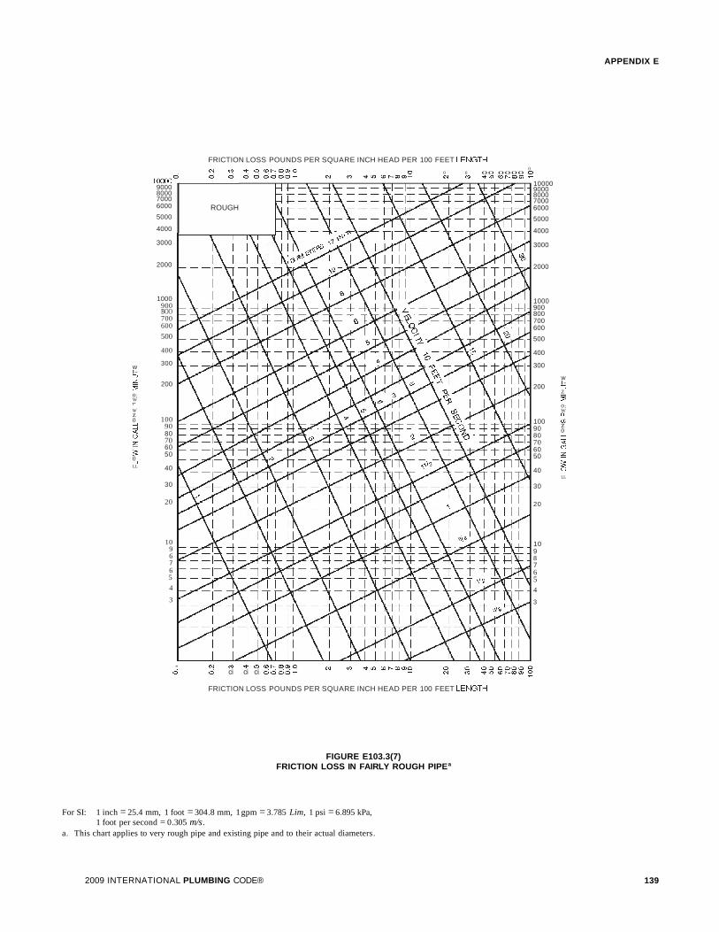
APPENDIX E
FRICTION LOSS POUNDS PER SQUARE INCH HEAD PER 100 FEET LEf\JGTH
10987654
3
0 00
00 0000 0(\J C'I:I 'ot' 10 (0 1'- CD 0) 'r
100009000800070006000
5000
4000
3000
2000
1000900800700600
500
400
300
w200
l-=>Z~0:WCL
100 (fJ
90 z0
80 .....J.....J
70 <r60 CJ
50 ~
;;:40 9
LL
30
20
ROUGH
N (') q- LO <D ...... coa:.oo ci ci ci 0000"":
N (') -q- LO <D ...... roa:.oo 0 0 a 0000"':
1096765
4
3
100000
9000800070006000
5000
4000
3000
2000
1000900BOO700600
500
400
w 300l-=>~ 200~
0:W0.-
Wz
1000.....J 90.....J<C 80(2)
70~ 60$: 500.....JLL 40
30
20
FRICTION LOSS POUNDS PER SQUARE INCH HEAD PER 100 FEET LEf\JGTH
FIGURE E103.3(7)FRICTION LOSS IN FAIRLY ROUGH PIPEa
For SI: 1 inch = 25.4 mm, 1 foot = 304.8 mm, 1gpm = 3.785 Lim, 1 psi = 6.895 kPa,1 foot per second = 0.305 m/s.
a. This chart applies to very rough pipe and existing pipe and to their actual diameters.
2009 INTERNATIONAL PLUMBING CODE® 139

APPENDIX E
SECTION E201SELECTION OF PIPE SIZE
E201.1 Size of water-service mains, branch mains and risers. The minimum size water service pipe shall be 3/4 inch (19.1mm) . The size of water service mains, branch mains and risersshall be determined according to water supply demand [gpm(Lim) ], available water pressure [psi (kPa)] and friction lossdue to the water meter and developed length of pipe [feet (m)],including equivalent length of fittings. The size of each waterdistribution system shall be determined according to the procedure outlined in this section or by other design methods conforming to acceptable engineering practice and approved bythe code official:
1. Supply load in the building water-distribution systemshall be determined by total load on the pipe being sized,in terms of water-supply fixture units (w.s.f.u.), asshown in Table EI03.3(2). For fixtures not listed, choosea w.s.f.u. value of a fixture with similar flow characteristics.
2. Obtain the minimum daily static service pressure [psi(kPa)] available (as determined by the local waterauthority) at the water meter or other source of supply atthe installation location. Adjust this minimum dailystatic pressure [psi (kPa)] for the following conditions:
2.1. Determine the difference in elevation betweenthe source of supply and the highest water supplyoutlet. Where the highest water supply outlet islocated above the source ofsupply, deduct 0.5 psi(3.4 kPa) for each foot (0.3 m) of difference inelevation. Where the highest water supply outletis located below the source of supply, add 0.5 psi(3.4 kPa) for each foot (0.3 m) of difference inelevation.
2.2. Where a water pressure reducing valve isinstalled in the water distribution system, theminimum daily static water pressure available is80 percent of the minimum daily static waterpressure at the source of supply or the set pressure downstream of the pressure reducing valve,whichever is smaller.
2.3. Deduct all pressure losses due to special equipment such as a backflow preventer, water filterand water softener. Pressure loss data for eachpiece of equipment shall be obtained through themanufacturer of such devices.
2.4. Deduct the pressure in excess of 8 psi (55 kPa)due to installation of the special plumbing fixture' such as temperature controlled shower andflushometer tank water closet.
Using the resulting minimum available pressure, find the corresponding pressure range inTable E201.1.
3. The maximum developed length for water piping is theactual length of pipe between the source of supply andthe most remote fixture, including either hot (through thewater heater) or cold water branches multiplied by a fac-
140
tor of 1.2 to compensate for pressure loss throughfittings.
Select the appropriate column in Table E201.1 equalto or greater than the calculated maximum developedlength.
4. To determine the size of water service pipe, meter andmain distribution pipe to the building using the appropriate table, follow down the selected "maximum developedlength" column to a fixture unit equal to, or greaterthan the total installation demand calculated by using the"combined" water supply fixture unit column of TableEI03.3(2). Read the water service pipe and meter sizes inthe first left-hand column and the main distribution pipeto the building in the second left-hand column on thesame row.
5. To determine the size of each water distribution pipe,start at the most remote outlet on each branch (either hotor cold branch) and, working back toward the main distribution pipe to the building, add up the water supplyfixture unit demand passing through each segment of thedistribution system using the related hot or cold columnof Table EI03.3(2). Knowing demand, the size of eachsegment shall be read from the second left-hand columnof the same table and maximum developed length column selected in Steps 1 and 2, under the same or nextsmaller size meter row. In no case does the size of anybranch or main need to be larger that the size of the maindistribution pipe to the building established in Step 4.
SECTION E202DETERMINATION OF PIPE VOLUMES
E202.1 Determining volume of piping systems. Whererequired for engineering design purposes, Table E202.1 shallbe used to determine the approximate internal volume of waterdistribution piping.
2009 INTERNATIONAL PLUMBING CODE®

TABLE E201.1MINIMUM SIZE OF WATER METERS, MAINS AND DISTRIBUTION PIPING
BASED ON WATER SUPPLY FIXTURE UNIT VALUES (w.s.f.u.)
APPENDIX E
METER AND SERVICE PIPE DISTRIBUTION PIPE(inches) (inches) MAXIMUM DEVELOPMENT LENGTH (feet)
Pressure Range 30 to 39 psi 40 60 80 100 150 200 250 300 400 500
3/4
1/2
3 2.5 2 1.5 1.5 1 1 0.5 0.5 0 0
3/4
3/4 9.5 7.5 6 5.5 4 3.5 3 2.5 2 1.5
3/4 1 32 25 20 16.5 11 9 7.8 6.5 5.5 4.5
1 1 32 32 27 21 13.5 10 8 7 5.5 5
3/4 11/ 4 32 32 32 32 30 24 20 17 13 10.5
1 11/ 4 80 80 70 61 45 34 27 22 16 12
11/ 2 11/ 4 80 80 80 75 54 40 31 25 17.5 13
1 11/ 2 87 87 87 87 84 73 64 56 45 36
11/ 2 11/ 2 151 151 151 151 117 92 79 69 54 43
2 11/ 2 151 151 151 151 128 99 83 72 56 45
1 2 87 87 87 87 87 87 87 87 87 86
11/ 2 2 275 275 275 275 258 223 196 174 144 122
2 2 365 365 365 365 318 266 229 201 160 134
2 21/ 2 533 533 533 533 533 495 448 409 353 311
METER AND SERVICE PIPE DISTRIBUTION PIPE(inches) (inches) MAXIMUM DEVELOPMENT LENGTH (feet)
Pressure Range 40 to 49 psi 40 60 80 100 150 200 250 300 400 500
3/4
1/2
3 3 2.5 2 1.5 1.5 1 1 0.5 0.5 0.5
3/4
3/4 9.5 9.5 8.5 7 5.5 4.5 3.5 3 2.5 2
3/4 1 32 32 32 26 18 13.5 10.5 9 7.5 6
1 1 32 32 32 32 21 15 11.5 9.5 7.5 6.5
3/4 11/ 4 32 32 32 32 32 32 32 27 21 16.5
1 11/ 4 80 80 80 80 65 52 42 35 26 20
11/ 2 11/ 4 80 80 80 80 75 59 48 39 28 21
1 11/ 2 87 87 87 87 87 87 87 78 65 55
11/ 2 11/ 2 151 151 151 151 151 130 109 93 75 63
2 11/ 2 151 151 151 151 151 139 115 98 77 64
1 2 87 87 87 87 87 87 87 87 87 87
11/ 2 2 275 275 275 275 275 275 264 238 198 169
2 2 365 365 365 365 365 349 304 270 220 185
2 21/ 2 533 533 533 533 533 533 533 528 456 403
(continued)
2009 INTERNATIONAL PLUMBING CODE® 141

APPENDIX E
TABLE E201.1-continuedMINIMUM SIZE OF WATER METERS, MAINS AND DISTRIBUTION PIPING
BASED ON WATER SUPPLY FIXTURE UNIT VALUES (w.s.f.u.)
METER AND SERVICE PIPE DISTRIBUTION PIPE(inches) (inches) MAXIMUM DEVELOPMENT LENGTH (feet)
Pressure Range 50 to 60 psi 40 60 80 100 150 200 250 300 400 500
3/4 1// 3 3 2.5 2 1.5 1 1 1 0.5 0.5
3/4
3/4 9.5 9.5 9.5 8.5 6.5 5 4.5 4 3 2.5
3/4 1 32 32 32 32 25 18.5 14.5 12 9.5 8
1 1 32 32 32 32 30 22 16.5 13 10 8
3/4 11/ 4 32 32 32 32 32 32 32 32 29 24
1 11/ 4 80 80 80 80 80 68 57 48 35 28
11/ 2 11/ 4 80 80 80 80 80 75 63 53 39 29
1 11/ 2 87 87 87 87 87 87 87 87 82 70
11/ 2 11/ 2 151 151 151 151 151 151 139 120 94 79
2 11/ 2 151 151 151 151 151 151 146 126 97 81
1 2 87 87 87 87 87 87 87 87 87 87
11/ 2 2 275 275 275 275 275 275 275 275 247 213
2 2 365 365 365 365 365 365 365 329 272 232
2 21/ 2 533 533 533 533 533 533 533 533 353 486
METER AND SERVICE PIPE DISTRIBUTION PIPE(inches) (inches) MAXIMUM DEVELOPMENT LENGTH (feet)
Pressure Range Over 60 40 60 80 100 150 200 250 300 400 500
3/4
1/2
3 3 3 3 2.5 2 1.5 1.5 1 1 0.5
3/4
3/4 9.5 9.5 9.5 9.5 7.5 6 5 4.5 3.5 3
3/4 1 32 32 32 32 32 24 19.5 15.5 11.5 9.5
1 1 32 32 32 32 32 28 28 17 12 9.5
3/4 11/ 4 32 32 32 32 32 32 32 32 32 30
1 11/ 4 80 80 80 80 80 80 69 60 46 36
11/ 2 11/ 4 80 80 80 80 80 80 76 65 50 38
1 11/ 2 87 87 87 87 87 87 87 87 87 84
11/ 2 11/ 2 151 151 151 151 151 151 151 144 114 94
2 11/ 2 151 151 151 151 151 151 151 151 118 97
1 2 87 87 87 87 87 87 87 87 87 87
11/ 2 2 275 275 275 275 275 275 275 275 275 252
2 2 365 368 368 368 368 368 368 368 318 273
2 21/ 2 533 533 533 533 533 533 533 533 533 533
For 51: 1 inch = 25.4, 1 foot = 304.8 mm.a. Minimum size for building supply is 3/4-inch pipe.
142 2009 INTERNATIONAL PLUMBING CODE®

TABLE E202.1INTERNAL VOLUME OF VARIOUS WATER DISTRIBUTION TUBING
APPENDIX E
OUNCES OF WATER PER FOOT OF TUBE
Size Nominal, CompositeInch Copper Type M Copper Type L Copper Type K CPVC CTS SDR 11 CPVC SCH 40 ASTM F 1281 PEX CTS SDR 9
3/8 1.06 0.97 0.84 N/A 1.17 0.63 0.64
1/2 1.69 1.55 1.45 1.25 1.89 1.31 1.18
3/4 3.43 3.22 2.90 2.67 3.38 3.39 2.35
1 5.81 5.49 5.17 4.43 5.53 5.56 3.91
11/ 4 8.70 8.36 8.09 6.61 9.66 8.49 5.81
11/ 2 12.18 11 .83 11.45 9.22 13.20 13.88 8.09
2 21.08 20.58 20.04 15.79 21.88 21.48 13.86
For 51: 1 ounce = 0.030 liter.
2009 INTERNATIONAL PLUMBING CODE® 143

144 2009 INTERNATIONAL PLUMBING CODE®

APPENDIX F
STRUCTURAL SAFETY
The provisions contained in this appendix are not mandatory unless specifically referenced in the adopting ordinance.
SECTION F101CUTTING, NOTCHING AND
BORING IN WOOD MEMBERS
[B] FIOI.I Joist notching. Notches on the ends ofjoists shallnot exceed one-fourth the joist depth. Holes bored in joistsshall not be within 2 inches (51 mm) of the top or bottom of thejoist, and the diameter of any such hole shall not exceedone-third the depth of the joist. Notches in the top or bottom ofjoists shall not exceed one sixth the depth and shall not belocated in the middle third of the span.
[B] FIOI.2 Stud cutting and notching. In exterior walls andbearing partitions, any wood stud is permitted to be cut ornotched to a depth not exceeding 25 percent of its width. Cutting or notching of studs to a depth not greater than 40 percentof the width of the stud is permitted in nonbearing partitionssupporting no loads other than the weight of the partition.
[B] FIOI.3 Bored holes. A hole not greater in diameter than 40percent of the stud width is permitted to be bored in any woodstud. Bored holes not greater than 60 percent of the width of thestud are permitted in nonbearing partitions or in any wall whereeach bored stud is doubled, provided not more than two suchsuccessive doubled studs are so bored. In no case shall the edgeof the bored hole be nearer than 0.625 inch (15.9 mm) to theedge of the stud. Bored holes shall not be located at the samesection of stud as a cut or notch.
[B] FIOI.4 Cutting, notching and boring holes in structuralsteel framing. The cutting, notching and boring of holes instructural steel framing members shall be as prescribed by theregistered design professional.
[B] FIOI.5 Cutting, notching and boring holes incold-formed steel framing. Flanges and lips of load-bearingcold-formed steel framing members shall not be cut or notched.Holes in webs of load-bearing cold-formed steel framing members shall be permitted along the centerline of the web of theframing member and shall not exceed the dimensionallimitations, penetration spacing or minimum hole edge distance asprescribed by the registered design professional. Cutting,notching and boring holes of steel floor/roof decking shall beas prescribed by the registered design professional.
[B] FIOI.6 Cutting, notching and boring holes innonstructural cold-formed steel wall framing. Flanges andlips of nonstructural cold-formed steel wall studs shall not becut or notched. Holes in webs of nonstructural cold-formedsteel wall studs shall be permitted along the centerline of theweb of the framing member, shall not exceed 11/ 2 inches (38mm) in width or 4 inches (102 mm) in length, and the holesshall not be spaced less than 24 inches (610 mm) center to center from another hole or less than 10 inches (254 mm) from thebearing end.
2009 INTERNATIONAL PLUMBING CODE® 145

146 2009 INTERNATIONAL PLUMBING CODE®

APPENDIX G
VACUUM DRAINAGE SYSTEM
The provisions contained in this appendix are not mandatory unless specifically referenced in the adopting ordinance.
SECTION G101VACUUM DRAINAGE SYSTEM
G101.1 Scope. This appendix provides general guidelines forthe requirements for vacuum drainage systems.
GI0l.2 General requirements.
GI0l.2.1 System design. Vacuum drainage systems shallbe designed in accordance with manufacturer's recommendations. The system layout, including piping layout, tankassemblies, vacuum pump assembly and other components/designs necessary for proper function of the systemshall be per manufacturer's recommendations. Plans, specifications and other data for such systems shall be submittedto the local administrative authority for review and approvalprior to installation.
G101.2.2 Fixtures. Gravity-type fixtures used in vacuumdrainage systems shall comply with Chapter 4 of this code.
G101.2.3 Drainage fixture units. Fixture units for gravitydrainage systems which discharge into or receive dischargefrom vacuum drainage systems shall be based on values inChapter 7 of this code.
G101.2.4 Water supply fixture units. Water supply fixtureunits shall be based on values in Chapter 6 of this code withthe addition that the fixture unit of a vacuum-type watercloset shall be "1."
G101.2.5 Traps and cleanouts. Gravity-type fixtures shallbe provided with traps and cleanouts in accordance withChapters 7 and 10 of this code.
G101.2.6 Materials. Vacuum drainage pipe, fitting andvalve materials shall be as recommended by the vacuumdrainage system manufacturer and as permitted by thiscode.
G101.3 Testing and demonstrations. After completion of theentire system installation, the system shall be subjected to avacuum test of 19 inches (483 mm) of mercury and shall beoperated to function as required by the administrative authorityand the manufacturer. Recorded proof of all tests shall be submitted to the administrative authority.
GI0l.4 Written instructions. Written instructions for theoperations, maintenance, safety and emergency proceduresshall be provided by the building owner as verified by theadministrative authority.
2009 INTERNATIONAL PLUMBING CODE® 147

148 2009 INTERNATIONAL PLUMBING CODE®

INDEX
AABS PIPE
Where permitted Table 605.3, Table 605.5,Table 702.1, Table 702.2, Table 702.3, Table 702.4
ACCESS TOCleanouts 708Fixtures 405.2Interceptors and separators 1003.10
ACCESSIBLE PLUMBING FACILITIES 404ADMINISTRATION
Applicability 102Approval 105,107.5,106.5.7Inspections 107Intent 101.3Maintenance 102.3Means of appeal 109Scope 101.2Validity 106.5.2Violations 108
AIR ADMITTANCE VALVESDefinition 202Where permitted 917
AIR BREAKDefinition 202Method of providing 802.1.5, 802.1.6,
802.1.8,802.1.7,802.2Required 802.2.2
AIR GAPDefinition 202Method of providing 608.15.1, 802.2.1Required 608.15.1, 802.1, 802.1.1, 802.1.2
802.1.3,802.1.4,802.1.5,802.1.6,802.1.7AIR TEST 312.3,312.5,312.7ALTERATIONS AND REPAIRS 102.4ALTERNATIVE MATERIALS AND
EQUIPMENT 105.2APPROVED
Definition 202ASBESTOS-CEMENT PIPE
Where permitted Table 702.2, Table 702.3ATMOSPHERIC VACUUM BREAKER ... Table 608.1,
608.13.6, 608.15.4,608.15.4.1,608.16.5
AUTOMATIC CLOTHES WASHER 406
BBACKFILLING 306.3
2009 INTERNATIONAL PLUMBING CODE®
BACKFLOW PREVENTERDefinition 202Required 608.1Standards Table 608.1
BACKFLOW PROTECTION 608.1BACKWATER VALVES
Where required 715BALL COCK (see FILL VALVE)BAROMETRIC LOOP 608.13.4BATHTUBS 407BEDPAN STEAMERS 202BEDPAN WASHERS 202BIDETS 408BOOSTER SYSTEM 606.5BOTTLING ESTABLISHMENT 1003.7BRASS PIPE
Where permitted Table 605.3, Table 605.4,Table 605.8, Table 702.1
BUILDING DRAINBranches of Table 710.1 (2)Definition 202Material Table 702.1, Table 702.2Sizing Table 710.1 (1)
BUILDING DRAINAGE SYSTEMSBelow sewer level 712.1
BUILDING SEWERDefinition 202Material. Table 702.3Sizing Table 710.1 (1)
BUILDING SYSTEMSConnection to public sewer 701.2
BUILDING TRAPS 1002.6
cCAST-IRON PIPE
Materials Table 702.1, Table 702.2,Table 702.3, Table 702.4
CAULKING FERRULES 705.19.5, 705.21CHANGE IN DIRECTION OF DRAINAGE
PIPING Table 706.3CHEMICAL WASTE
Exclusion from the sewer 803.3Neutralizing 803.2Requirements 702.5
CHLORINATED POLYVINYL/PIPE OR TUBINGWhere permitted Table 605.3, Table 605.4
149

INDEX
CIRCUIT VENT 911CLAY PIPE Table 702.3CLEANOUTS
Base of stack 708.3.4Building drain 708.3.1, 708.3.5Change of direction 708.3.3Clearances 708.8Definition 202Direction of flow 708.5Horizontal drains 708.3.1Location of 708.3Manholes 708.3.6Plugs, materials for 708.2Prohibited installation of 708.6Sewers 708.3.2Size 708.7, 708.8
CLEARANCES 502.5CODE OFFICIAL
Application for permit 106.3Appointment 103.2Definition 202Department records 104.7Duties and powers 104General 104.1Identification 104.5Inspections 107
COMBINATION DRAIN AND VENT SYSTEM 912COMBINED DRAIN 202COMMON VENT 202, 908CONCRETE PIPE
Where permitted Table 702.3CONDUCTOR 202CONFLICTS 301.7CONNECTION TO PLUMBING SYSTEM
REQUIRED 701.2CONNECTIONS TO SUMPS AND EJECTORS
Below sewer level 712.1CONSERVATION
Fixtures 604.4Flow rates Table 604.3Insulation 505,607.2.1
CONSTRUCTION DOCUMENTS 106.3.1CONTROLLED FLOW STORM DRAINAGE 1110COPPER OR COPPER-ALLOY PIPE OR TUBING
Where permitted Table 605.3, Table 605.4CROSS CONNECTIONS 608CUTTING OR NOTCHING, STRUCTURAL
MEMBERS 307.2, Appendix F
150
DDESIGN PROFESSIONAL 105.4.2,105.4.3,
105.4.4, 105.4.5, 107.2.2, 109.2.1DETRIMENTAL WASTES 302DISHWASHING MACHINE 409DISINFECTION OF POTABLE WATER SYSTEM.. 610DISTANCE OF TRAP FROM VENT Table 906.1DISTRIBUTION SYSTEM (See WATER)DRAIN
Roof 1105Storm 1106
DRAINAGE FIXTURE UNITSDefinition, fixture unit 202Values for continuous flow 709.3Values for fixtures Table 709.1
DRAINAGE SYSTEMConnection to sewer or private
disposal system 701.2Determining load and size 710.1Fixture units Table 709.1Indirect waste 802Joints 705Materials 702Material detrimental to 302Offset sizing 711Provisions for future fixtures 710.2Sizing Table 710.1 (1), Table 710.1 (2)Slope of piping Table 704.1Sumps and ejectors 712Testing 312
DRINKING FOUNTAINS Table 403.1, 410
EEJECTORS 712ELEVATOR SHAFT 301.6EMPLOYEE FACILITIES 403.3EXISTING BUILDING PLUMBING SYSTEMS 102.2
FFACILITIES 403FAMILY AND ASSISTED USE 403.1.2FAUCETS 424FEES 106.6FERRULES 705.19.1, 705.21FILL VALVE 425.3.1FITTINGS
Drainage system 706Material standards 605.5, Table 605.5,
702.4, Table 702.4
2009 INTERNATIONAL PLUMBING CODE®

FIXTURE CALCULATIONS 403.1.1FIXTURE FITTINGS 424FIXTURE TRAPS 1002
Acid-resisting 1002.9Building 1002.6Design of 1002.2For each fixture 1002.1Prohibited 1002.3Seals 1002.4Setting and protection 1002.7Size 1002.5
FIXTURE UNITSDefinition 202Values for continuous flow 709.3Values for fixtures 709.1, Table 709.1
FIXTURES (See PLUMBING FIXTURES)FLOOD LEVEL RIM 202FLOOD-RESISTANT CONSTRUCTION
Design flood elevation 202Flood hazard area 202Flood hazard resistance 309
FLOOR DRAINS 412, Table 709.1FLOOR DRAINS, EMERGENCY 202FLOOR FLANGES 405.4.1, 405.4.2FLOW RATES 604.3, Table 604.3
Table 604.4, 604.10FLUSHING DEVICES
Flush tanks 425.2, 425.3, 604.3, 604.5Flushometer tanks 425.2, 604.3, 604.5Flushometer valves 425.2, 604.3Required 425
FOOD HANDLING DRAINAGE 802.1.1, 802.1.8FOOD WASTE GRINDER 413FREEZING, PROTECTION OF
BACKFLOW DEVICES 608.14.2FREEZING, PROTECTION OF PIPES 305.6FROST CLOSURE 904.2FUTURE FIXTURES 704.4
GGALVANIZED STEEL PIPE Table 605.3,
Table 605.4, 605.18GARBAGE CAN WASHERS 414GARBAGE DISPOSALS 413GENERAL REGULATIONS 301
Conflicts 301.7Connection to plumbing system 301.3Connection to public water and sewer .. 301.3, 301.4Elevator machinery rooms 301.6Health and safety... 108.7, 108.7.1,108.7.2,108.7.3Materials detrimental 302, 302.1, 302.2
2009 INTERNATIONAL PLUMBING CODE®
INDEX
Piping measurements 301.5Protection of pipes 305Rodentproofing 304, 304.1, 304.2, 304.3, 304.4Sleeves 305.4Strains and stresses in pipe 305.3Toilet facilities for workers 311Trenching, excavation and backfill 306Washroom requirements 310
GREASE INTERCEPTORS 202, 1003Approval 1003.3.4Capacity Table 1003.3.4.1,
1003.4.2.1, 1003.4.2.2In commercial buildings 1003.5Not required 1003.3.3Required 1003.1
GUTTERS 1106.6, Table 1106.6
HHANGERS AND SUPPORTS
Attachment to buildings 308.4Definitions 202Material 308.3Seismic 308.2Spacing Table 308.5
HEALTH AND SAFETY 101.3HEALTH CARE PLUMBING 422, 609, 713HEAT EXCHANGER PROTECTION 608.16.3HORIZONTAL
Slope for drainage pipe 704.1HOSPITAL PLUMBING FIXTURES 422
Clinical sinks 422.6Height of special controls 422.10Sterilizer equipment 422.9
HOT WATERDefinition 202Flow of hot water to fixtures 607.4Heaters and tanks Chapter 5Recirculating pump 607.2.3Supply system 607
HOUSE TRAP 1002.6
INDIRECT WASTE 802Air gap or break 802.2.1, 802.2.2Food handling establishment 802.1.1Receptors 802.3Special wastes 803Waste water temperature 803.1Where required 802.1
INDIVIDUAL VENT 907
151

INDEX
INSPECTION 107.1Final 107.1Reinspection 107.4.3Required 107.2Rough-in 107.2Scheduling of 107.2Testing 107.4
INSPECTOR (See CODE OFFICIAL)INSULATION 505,607.2.1INTERCEPTORS AND SEPARATORS 1003
Access to 1003.10Approval of 1003.2, 1003.4Bottling establishments 1003.7Capacity of grease interceptors Table 1003.3.4.1Definition 202Laundries 1003.6Not required 1003.3.3Oil and flammable liquids separators 1003.4Rate of flow control for grease interceptors .. 1003.3.4.2Required 1003.1Slaughterhouses 1003.8Venting 905.4,1003.9
IRRIGATION, LAWN 608.16.5ISLAND FIXTURE VENT 913
JJOINTS AND CONNECTIONS 605, 705
ABS plastic pipe 605.10, 705.2Asbestos-cement pipe 605.11, 705.3Between different materials 605.23, 705.4, 705.19Brass pipe 605.12, 705.4Brazed joints 605.12.1, 605.14.1,
605.15.1, 705.9.1, 705.10.1Cast-iron pipe 705.5Caulked joint 705.5.1, 705.11.1Concrete pipe 705.6Copper or copper-alloy pipe 605.14, 705.9Copper or copper-alloy tubing 605.15, 705.10CPVC plastic pipe 605.16Expansionjoints 308.8Galvanized steel pipe 605.18Mechanicaljoints 605, 705Polyethylene plastic pipe or tubing 605.19Polypropylene plastic pipe or tubing 605.19Prohibited 605.9, 707PVC plastic pipe 605.22, 705.14Slip joints 405.8, 1002.2Solderedjoints 605.14.3,605.15.4,
705.9.3,705.10.3Solvent cementing 605, 705Stainless steel 605.23
152
Threaded 605.10.3,605.12.3,605.14.4,605.16.3, 605.18.1, 605.22.3, 705.2.3,
705.9.4,705.12.1,705.14.3Vitrified clay pipe 705.15Welded 605.12.4, 605.14.5, 705.4.4, 705.9.5
KKITCHEN 418
LLAUNDRIES 1003.6LAUNDRY TRAY 415LAVATORIES 416LEAD PIPE 202LEADERS 1106LIGHT AND VENTILATION REQUIREMENT 310.1LOADING, FIXTURE UNIT VALVE Table 709
MMANHOLES 708.3.6MANIFOLDS 604.10MATERIAL
Above-ground drainage and vent pipe Table 702.1Alternative 105.2Approval 107.2.3Building sewer pipe 702.3Building storm sewer pipe 1102.4Chemical waste system 702.5Fittings Table 605.5, Table 702.4,
Table 1102.7Identification 303.1Joints 605, 705Roof drains 1105Sewer pipe 702.3Standards Chapter 13Storm drainage pipe Table 1102.4Subsoil drain pipe 1102.5Underground building drainage and vent pipe.. 702.2Vent pipe 702.1, 702.2Water distribution pipe Table 605.4Water service pipe Table 605.3
MATERIAL, FIXTURESQuality 402.1Special use 402.2
MATERIAL, SPECIALCaulking ferrules 705.21Cleanout plugs 708.2Sheet copper 402.3Sheet lead 402.4Soldering bushings 705.19.5
2009 INTERNATIONAL PLUMBING CODE®

MECHANICAL JOINTS 605, 705
NNONPOTABLE WATER 608.1, 608.8
oOFFSETS
Definitions 202Drainage 711Venting 915.1
OPENINGSThrough walls or roofs 305.5, 305.7
p
PERMITApplication for 106.3Conditions of 106.5Fees 106.6Suspension of 106.5.5
PIPINGConstruction documents 105.4.4Drainage, horizontal slope Table 704.1Drainage piping installation 704Drainage piping offset, size 711Joints 605, 705
PIPING PROTECTIONBackfilling 306.3Breakage 305.2Corrosion 305.1Footings 305.5Freezing 305.6Penetration. . . . . . . . . . . . . . . . . . . . . . . . . . . . . 305.5Tunneling 306.4
PLUMBING FACILITIES 403PLUMBING FIXTURES
Accessible 404Automatic clothes washers 406Bidet 408Clearances 405.3Definition 202Dishwashing machine 409Drainage fixture unit values Table 709.1Drinking fountain 410Emergency showers 411Eyewash stations 411Floor sinks 427Floor and trench drains 412Food waste grinders 413Future fixtures 704.4Garbage can washer 414
2009 INTERNATIONAL PLUMBING CODE®
INDEX
Garbage disposal 413Hospital 422Installation 405Joints at wall or floor 405.5Kitchen sink 418Laundry tray 415Lavatories 416Minimum facilities Table 403.1Ornamental pools 423.1Quality 402.1Separate facilities 403.2Setting 405.3Showers 417Sinks 418Slop sinks 418Urinals 419Water closets 420Water coolers 410Water supply protection 608
PLUMBING INSPECTOR (See CODE OFFICIAL)PNEUMATIC EJECTORS 712POLYETHYLENE PIPE OR TUBING
Cross-linked Table 605.3, Table 605.4PE-AL-PE Table 605.3, Table 605.4PEX-AL-PEX Table 605.3, Table 605.4
POLYPROPYLENE PIPE OR TUBINGWhere permitted Table 605.3, Table 605.4
POTABLE WATER, PROTECTION OF 608PRESSURE OF WATER DISTRIBUTION 604.6PROHIBITED
Joints and connection 605.9, 707Traps 1002.3
PROTECTION OF POTABLE WATER 608PUMPING EQUIPMENT 712PVC PIPE Table 605.3, Table 605.4,
Table 702.1, Table 702.2, Table 702.3
QQUALITY OF WATER
General 608.1
RRAINWATER DRAINAGE Chapter 11REDUCED PRESSURE PRINCIPLE
BACKFLOW PREVENTERDefinition 202Periodic inspections 312.10Standard Table 608.1Where required 608.15.2, 608.16.1, 608.16.2,
608.16.4, 608.16.4.1, 608.16.5, 608.16.6
153

INDEX
RELIEF VALVES 504.4, 504.5, 504.6Definition 202
RELIEF VENT 911.4, 914, 916.2Definition 202
ROOF DRAINS 1102.6, 1105Definition 202
ROUGH-IN INSPECTION 107.2
SSANITARY SEWER (See BUILDING SEWER)SANITARY TEES 706.3SCREWED JOINTS (See JOINTS AND
CONNECTIONS)SEPARATE FACILITIES 403.2SERVICE SINKS Table 403.1, 418SEWER (See BUILDING SEWER)SHEET COPPER 402.3SHEET LEAD 402.4SHOWER LINER 312.9,417.5.2SHOWERS Table 403.1,417SILL COCK 424, 608.15.4.2SINKS 418SIZING
Drainage system 710Fixture drain 709Fixture water supply 604.5Vent system 916Water distribution system 604Water service 603.1
SLAUGHTERHOUSES 1003.8SLEEVES 305.4SLIP JOINTS (See JOINTS AND CONNECTIONS)SOLDERING BUSHINGS 705.19SOLVENT CEMENTING (See JOINTS AND
CONNECTIONS)SPECIAL PLUMBING FIXTURES 423SPECIAL WASTES 803STAINLESS STEEL PIPE Table 605.3, Table 605.4STANDARDS
Material Chapter 13STANDPIPE DRAIN 802.4STEEL PIPE (See also MATERIAL)
Where permitted Table 605.4, Table 702.1,Table 702.2, Table 702.3,
Table 1102.4, Table 1102.5STERILIZER PIPE 422.9STORM DRAINS
Building size 1106.1Building subdrains 1112.1Building subsoil drains 1111.1Conductors and connections 1104
154
Definition 202General 1101Prohibited drainage 1101 .3Roof drains 1102.6, 1105Secondary roof drains 1107Sizing of conductors, leaders and storm drains. 1106Sizing of roof gutters 1106.6Sizing of vertical conductors and leaders 1106.2Traps 1103Values for continuous flow 1109Where required 1101.2
STRAPS (See HANGERS AND SUPPORTS)STRUCTURAL SAFETY 307, Appendix FSUBDRAIN BUILDING 1112.1SUBSOIL DRAIN PIPE 1111.1SUMP VENT 916.5SUMPS 1113SUPPORTS (See also PIPING PROTECTION) 308SWIMMING POOL
Definition 202SWIMMING POOL DRAINAGE 802.1.4
TTEMPERATURE AND PRESSURE RELIEF
VALVE 504TEMPERATURE OF WASTE WATER 803.1TEST
Drainage and vent air test 312.3Drainage and vent final test 312.4Drainage and vent water test. 312.2Forced sewer test . . . . . . . . . . . . . . . . . . . . . . . 31 2. 7Gravity sewer test 312.6Required tests 312.1Shower liner 312.19Test gauges 312.1.1Test of backflow prevention devices 312.10Test of conductors 312.8
THERMAL EXPANSION CONTROL 607.3THREADED JOINTS (See JOINTS AND
CONNECTIONS)TOILET FACILITIES FOR WORKERS 311TOILETS (See WATER CLOSETS)TRAP PRIMER 1002.4TRAPS
Acid-resisting 1002.9Building 1002.6Design 1002.2Prohibited types 1002.3Seal 1002.4Separate for each fixture 1002.1Size Table 709.1, Table 709.2
2009 INTERNATIONAL PLUMBING CODE®

TRENCH DRAINS 412TRENCHING, EXCAVATION AND BACKFILL 306TUNNELING 306.4
UUNDERGROUND DRAINAGE AND VENT PIPE. 702.2URINALS 419
VVACUUM BREAKERS Table 608.1, 608.13.5,
608.13.6, 608.13.8, 608.15.4VALVES
Air admittance 202, 917Backwater 715Definition 202Pressure reducing 604.8Relief 202, 504.4Stop and waste 608.7Temperature-actuated flow reduction valves 424.6Transfer valves 424.8
VENTIndividual 907Sizing 904.2, 908.3, 910.4,
912.3, 916.1, 916.2VENT RELIEF SIZE 914VENT STACK
Definition 202, 903.2VENTS AND VENTING
Branch vents 916.4.1Circuit 911Combination drain 912Common 908Definition 202Distance from trap Table 906.1Engineered systems 918Island fixture 913Required vent. 903.1Vent stack 903.2Vent terminal 904Waste stack 910Wet vent 909
WWALL HUNG WATER CLOSETS 420WASHING MACHINES 406WASTE
Indirect 802Special 803
WASTE STACK 910WASTE WATER TEMPERATURE 803.1
2009 INTERNATIONAL PLUMBING CODE®
INDEX
WATERBooster 606.5Cooler 410Cross connection 608.6Distribution piping material Table 605.4Excessive pressure 604.8Hammer 604.9
WATER CLOSETS 420WATER CONSERVATION
Fixtures 604.4Flow rates Table 604.4
WATER HEATER PAN 504.7WATER HEATERS Chapter 5WET VENT 909WIPED JOINTS 705.13.2WORKERS' TOILET FACILITIES 311
155

156 2009 INTERNATIONAL PLUMBING CODE®