
Codes and Standards in Digital Industrial Radiology - ndt.net · 1 Progress of Digital Radiology...
33
1 Progress of Digital Radiology Ewert, April. 2007 Codes and Standards in Digital Industrial Radiology by Uwe Ewert [email protected] http://www.bam.de INDE 2007 India, Chennai, April 25th , 2007 by U. Ewert
Transcript of Codes and Standards in Digital Industrial Radiology - ndt.net · 1 Progress of Digital Radiology...
1
Progress of Digital Radiology Ewert, April. 2007
Codes and Standards in Digital Industrial Radiology
byUwe Ewert
[email protected]://www.bam.de
[email protected]://www.bam.de
INDE 2007India, Chennai, April 25th , 2007 by U. Ewert
2
Progress of Digital Radiology Ewert, April. 2007
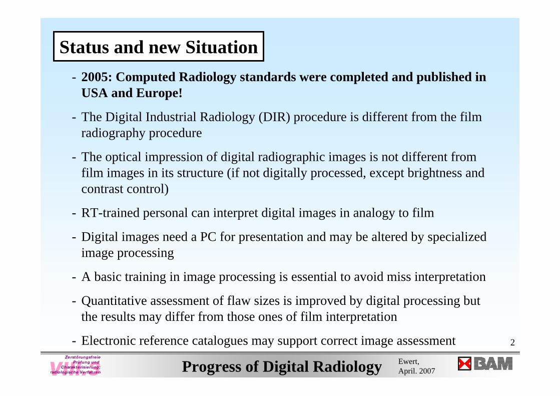
Status and new Situation- 2005: Computed Radiology standards were completed and published in
USA and Europe!
- The Digital Industrial Radiology (DIR) procedure is different from the film radiography procedure
- The optical impression of digital radiographic images is not different from film images in its structure (if not digitally processed, except brightness and contrast control)
- RT-trained personal can interpret digital images in analogy to film
- Digital images need a PC for presentation and may be altered by specialized image processing
- A basic training in image processing is essential to avoid miss interpretation
- Quantitative assessment of flaw sizes is improved by digital processing but the results may differ from those ones of film interpretation
- Electronic reference catalogues may support correct image assessment
3
Progress of Digital Radiology Ewert, April. 2007
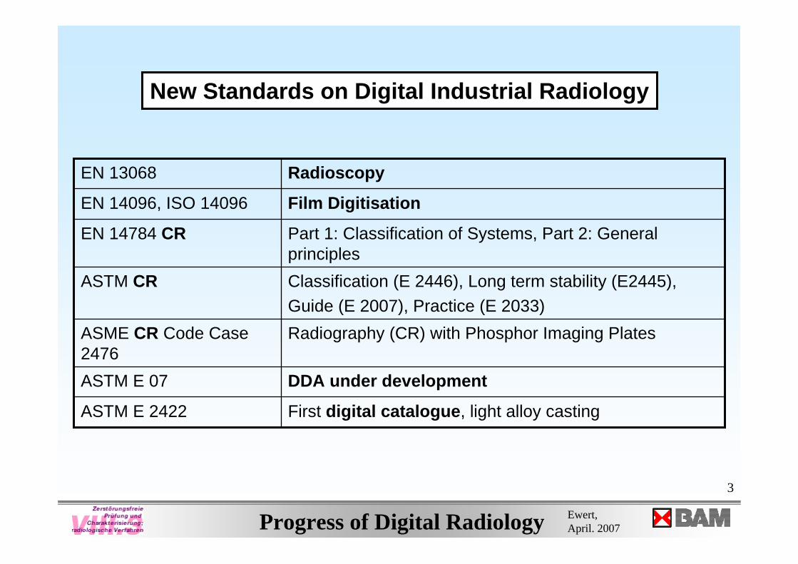
Radiography (CR) with Phosphor Imaging PlatesASME CR Code Case 2476
First digital catalogue, light alloy castingASTM E 2422
DDA under developmentASTM E 07
Part 1: Classification of Systems, Part 2: General principles
EN 14784 CR
RadioscopyEN 13068
Film DigitisationEN 14096, ISO 14096
Classification (E 2446), Long term stability (E2445), Guide (E 2007), Practice (E 2033)
ASTM CR
New Standards on Digital Industrial Radiology
4
Progress of Digital Radiology Ewert, April. 2007
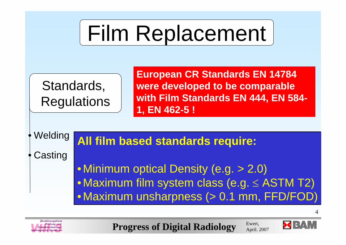
Film Replacement
Standards, Regulations
• Welding
• CastingAll film based standards require:
• Minimum optical Density (e.g. > 2.0)• Maximum film system class (e.g. ≤ ASTM T2) • Maximum unsharpness (> 0.1 mm, FFD/FOD)
European CR Standards EN 14784 were developed to be comparable with Film Standards EN 444, EN 584-1, EN 462-5 !
5
Progress of Digital Radiology Ewert, April. 2007
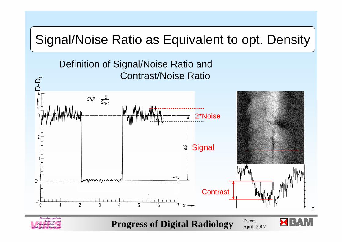
Signal/Noise Ratio as Equivalent to opt. Density
Definition of Signal/Noise Ratio andContrast/Noise Ratio
Signal
2*Noise
Contrast
D-D
0
0
6
Progress of Digital Radiology Ewert, April. 2007
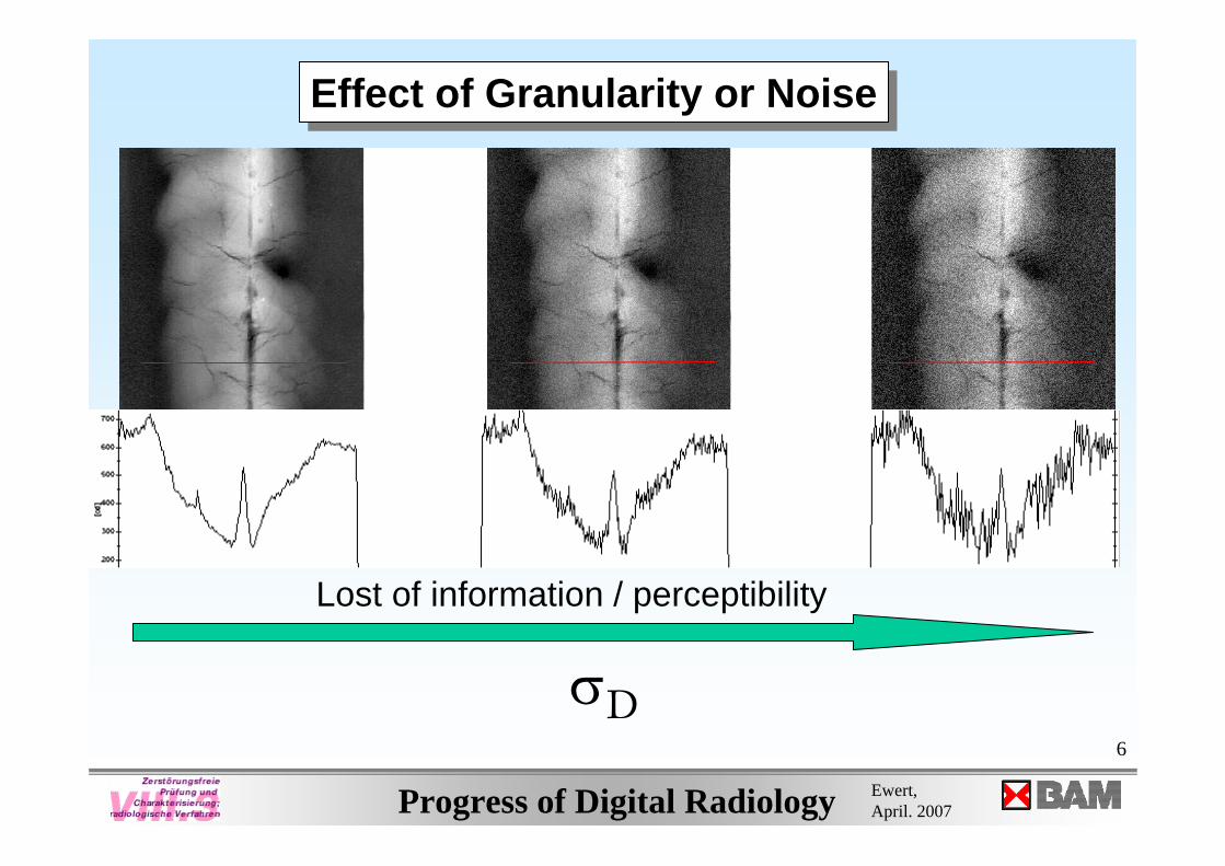
Effect of Granularity or NoiseEffect of Granularity or Noise
σD
Lost of information / perceptibility
7
Progress of Digital Radiology Ewert, April. 2007
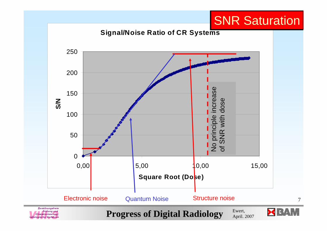
Signal/Noise Ratio of CR Systems
0
50
100
150
200
250
0,00 5,00 10,00 15,00
Square Root (Dose)
S/N
Electronic noise Quantum Noise Structure noise
No
prin
cipl
e in
crea
se
of S
NR
with
dos
e
SNR Saturation
8
Progress of Digital Radiology Ewert, April. 2007
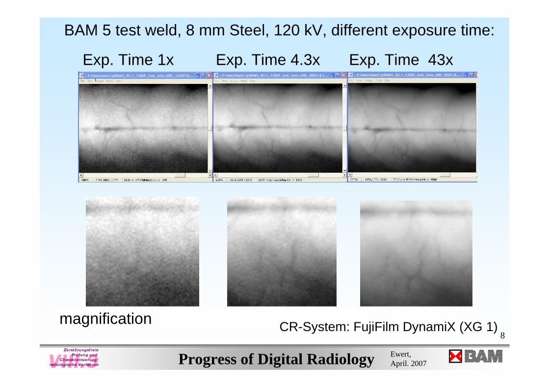
Exp. Time 1x Exp. Time 4.3x Exp. Time 43x
BAM 5 test weld, 8 mm Steel, 120 kV, different exposure time:
magnification CR-System: FujiFilm DynamiX (XG 1)
9
Progress of Digital Radiology Ewert, April. 2007
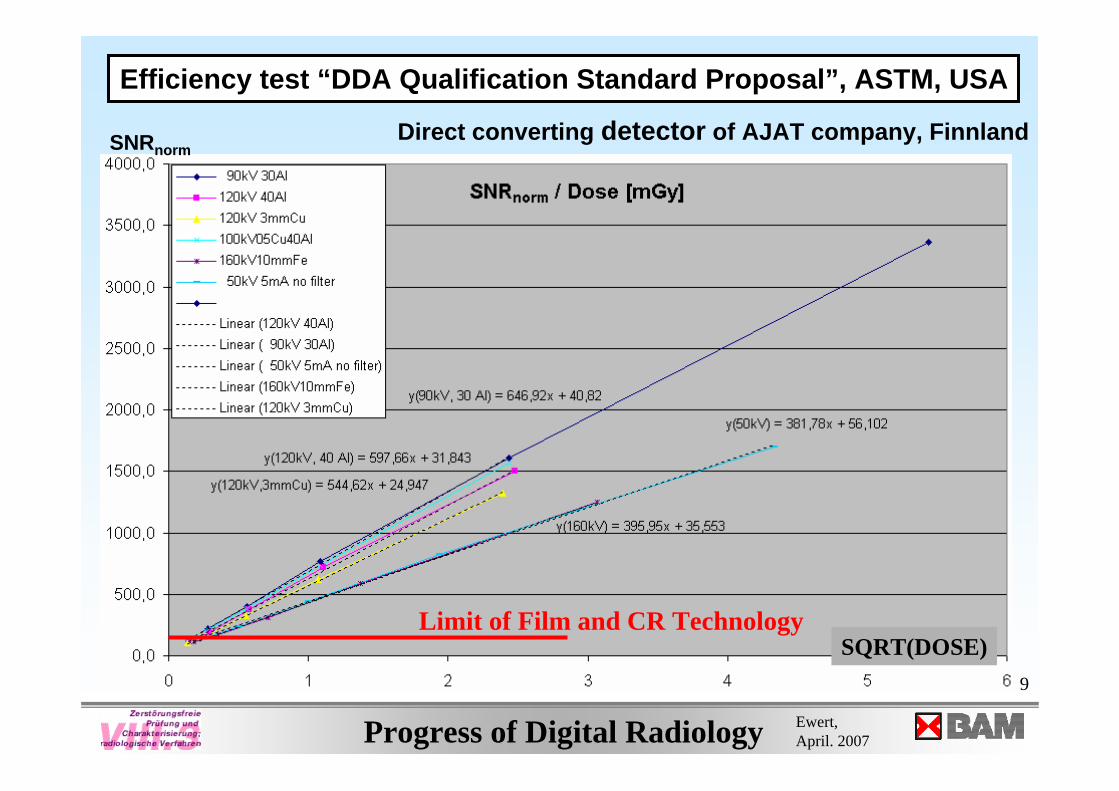
Efficiency test “DDA Qualification Standard Proposal”, ASTM, USA
SNRnormDirect converting detector of AJAT company, Finnland
Limit of Film and CR Technology SQRT(DOSE)
10
Progress of Digital Radiology Ewert, April. 2007
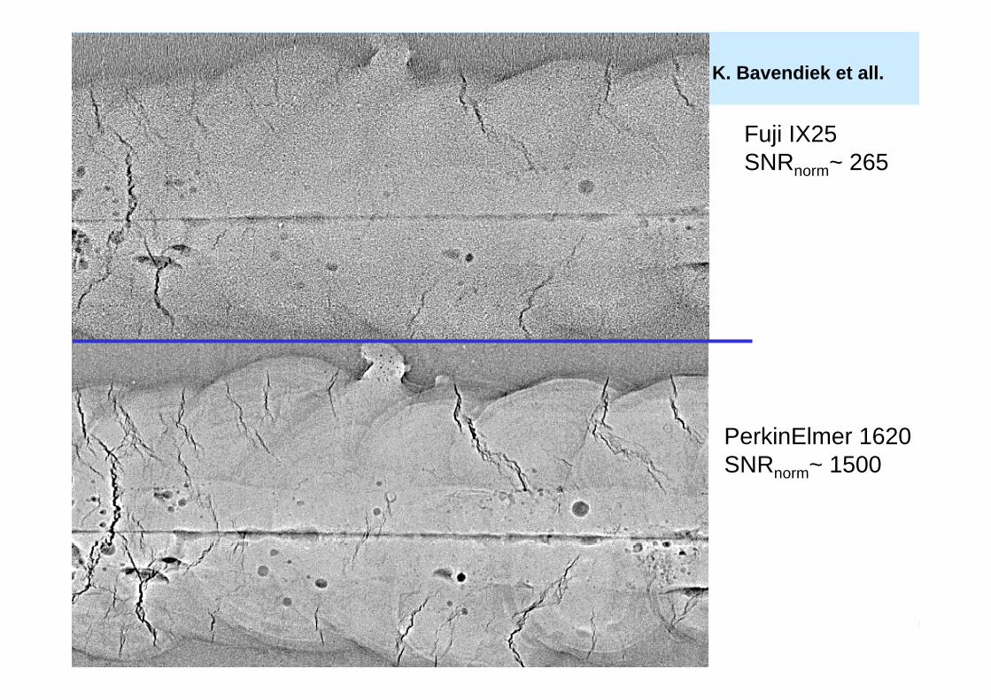
Fuji IX25SNRnorm~ 265
PerkinElmer 1620SNRnorm~ 1500
K. Bavendiek et all.
11
Progress of Digital Radiology Ewert, April. 2007
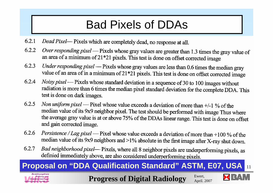
Bad Pixels of DDAs
Proposal on “DDA Qualification Standard” ASTM, E07, USA
12
Progress of Digital Radiology Ewert, April. 2007
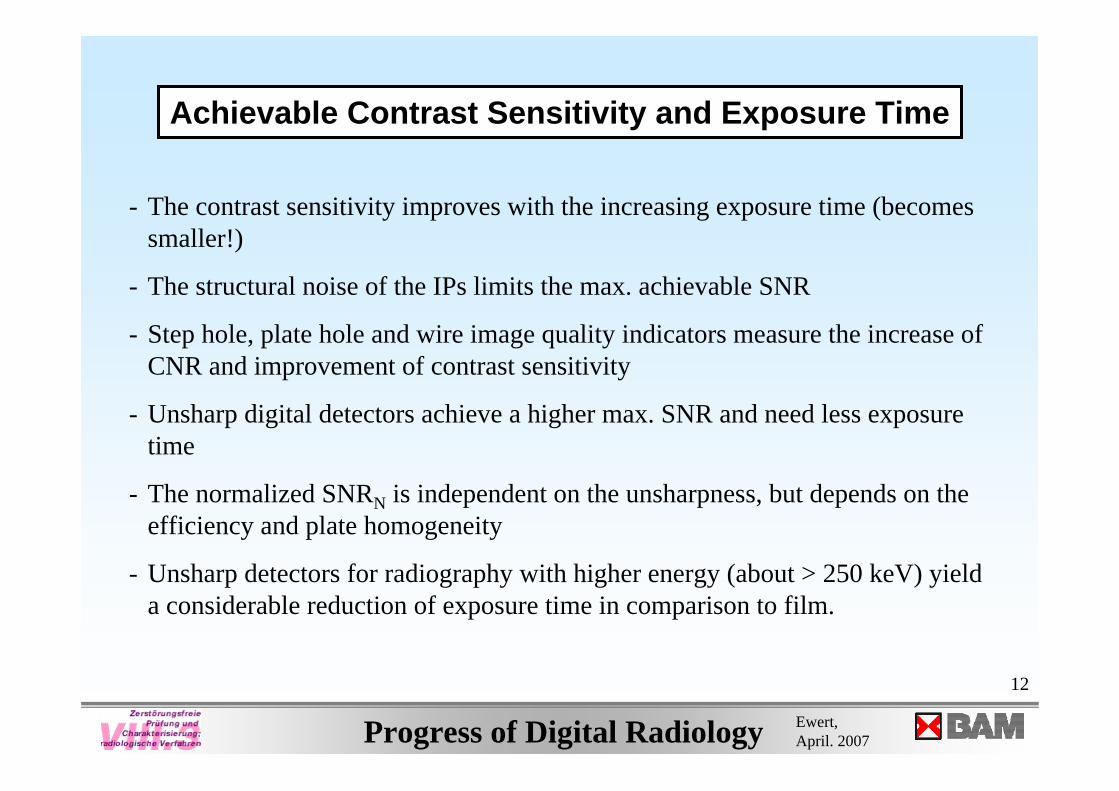
- The contrast sensitivity improves with the increasing exposure time (becomes smaller!)
- The structural noise of the IPs limits the max. achievable SNR
- Step hole, plate hole and wire image quality indicators measure the increase of CNR and improvement of contrast sensitivity
- Unsharp digital detectors achieve a higher max. SNR and need less exposure time
- The normalized SNRN is independent on the unsharpness, but depends on the efficiency and plate homogeneity
- Unsharp detectors for radiography with higher energy (about > 250 keV) yield a considerable reduction of exposure time in comparison to film.
Achievable Contrast Sensitivity and Exposure Time
13
Progress of Digital Radiology Ewert, April. 2007
CR System Selection
European StandardEN 14784-2
14
Progress of Digital Radiology Ewert, April. 2007
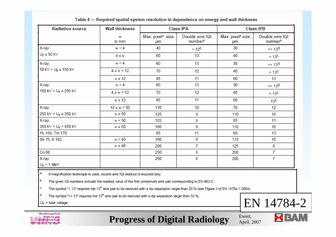
EN 14784-2
15
Progress of Digital Radiology Ewert, April. 2007
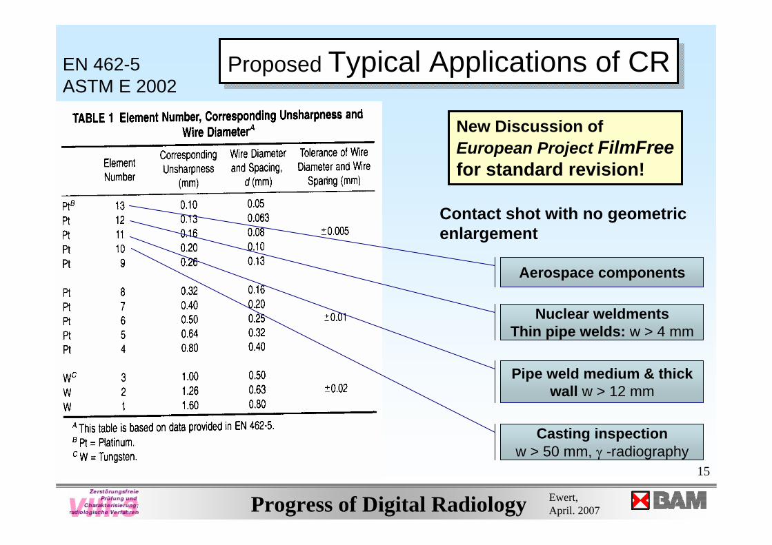
Contact shot with no geometric enlargement
Aerospace components
Nuclear weldmentsThin pipe welds: w > 4 mm
Casting inspectionw > 50 mm, γ -radiography
Pipe weld medium & thick wall w > 12 mm
Proposed Typical Applications of CRProposed Typical Applications of CREN 462-5ASTM E 2002
New Discussion of European Project FilmFreefor standard revision!
16
Progress of Digital Radiology Ewert, April. 2007
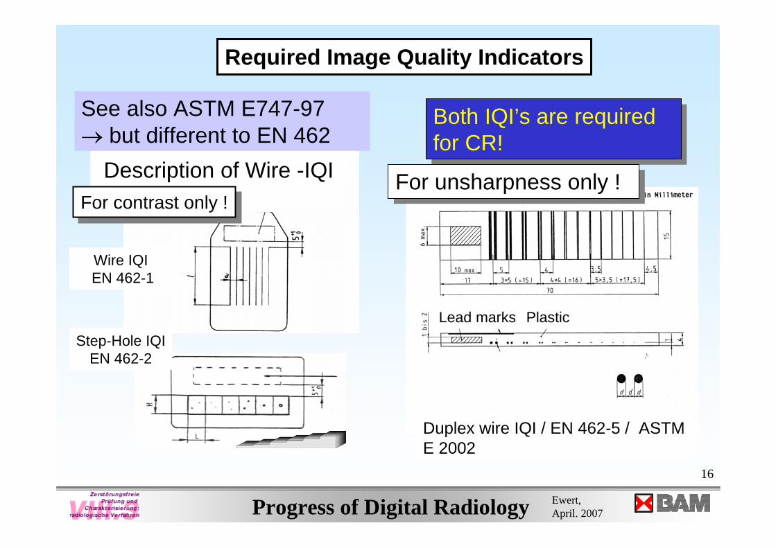
Wire IQI EN 462-1
Description of Wire -IQI
See also ASTM E747-97→ but different to EN 462
For contrast only !For contrast only !
Duplex wire IQI / EN 462-5 / ASTM E 2002
Lead marks Plastic
Both IQI’s are requiredfor CR!Both IQI’s are requiredfor CR!
For unsharpness only !For unsharpness only !
Step-Hole IQI EN 462-2
Required Image Quality Indicators
17
Progress of Digital Radiology Ewert, April. 2007
Digital Radiology for Weld Inspection in Europe
Digital Radiology for Weld Inspection in Europe
18
Progress of Digital Radiology Ewert, April. 2007
Quality Levels for Welding are defined in:
EN ISO 5817 and EN ISO 10042
- Basis for Manufacturer and User Contracts
- Harmonized with European Pressurised Equipment Directive!
Quality Levels for Welding are defined in:
EN ISO 5817 and EN ISO 10042
- Basis for Manufacturer and User Contracts
- Harmonized with European Pressurised Equipment Directive!
19
Progress of Digital Radiology Ewert, April. 2007
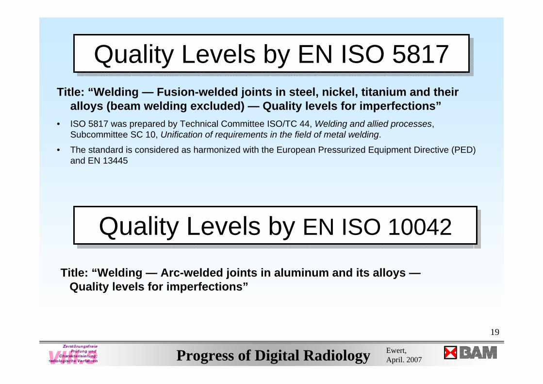
Quality Levels by EN ISO 5817 Quality Levels by EN ISO 5817 Title: “Welding — Fusion-welded joints in steel, nickel, titanium and their
alloys (beam welding excluded) — Quality levels for imperfections”• ISO 5817 was prepared by Technical Committee ISO/TC 44, Welding and allied processes,
Subcommittee SC 10, Unification of requirements in the field of metal welding.
• The standard is considered as harmonized with the European Pressurized Equipment Directive (PED) and EN 13445
Quality Levels by EN ISO 10042Quality Levels by EN ISO 10042
Title: “Welding — Arc-welded joints in aluminum and its alloys —Quality levels for imperfections”
20
Progress of Digital Radiology Ewert, April. 2007
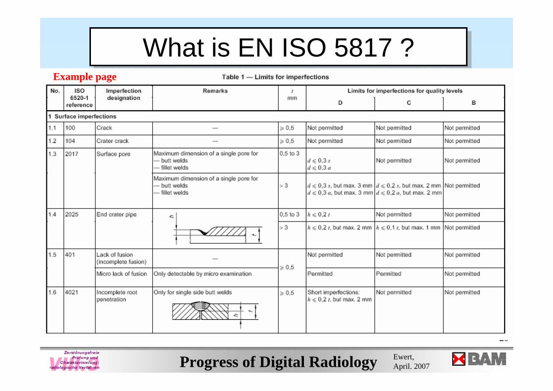
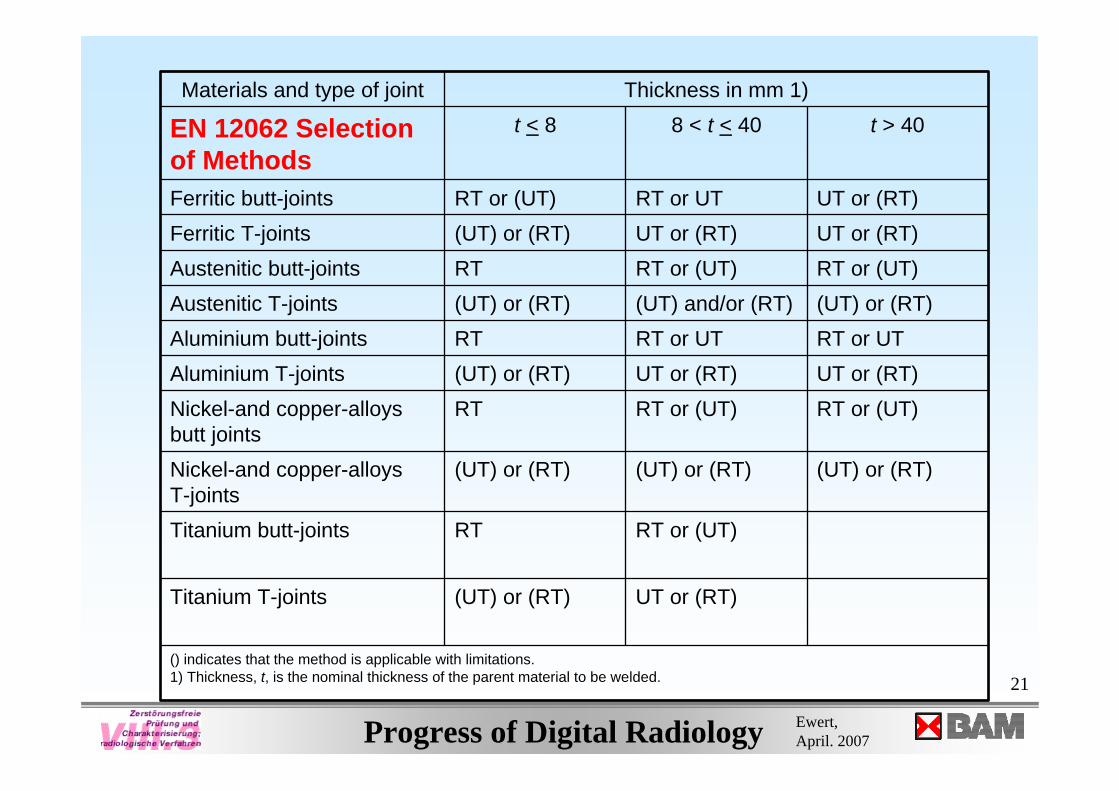
What is EN ISO 5817 ?What is EN ISO 5817 ?Example page
21
Progress of Digital Radiology Ewert, April. 2007
() indicates that the method is applicable with limitations.1) Thickness, t, is the nominal thickness of the parent material to be welded.
UT or (RT)(UT) or (RT)Titanium T-joints
RT or (UT)RTTitanium butt-joints
(UT) or (RT)(UT) or (RT)(UT) or (RT)Nickel-and copper-alloysT-joints
RT or (UT)RT or (UT)RTNickel-and copper-alloysbutt joints
UT or (RT)UT or (RT)(UT) or (RT)Aluminium T-jointsRT or UTRT or UTRTAluminium butt-joints(UT) or (RT)(UT) and/or (RT)(UT) or (RT)Austenitic T-jointsRT or (UT)RT or (UT)RTAustenitic butt-jointsUT or (RT)UT or (RT)(UT) or (RT)Ferritic T-jointsUT or (RT)RT or UTRT or (UT)Ferritic butt-joints
t > 40 8 < t < 40t < 8EN 12062 Selection of Methods
Thickness in mm 1)Materials and type of joint
22
Progress of Digital Radiology Ewert, April. 2007
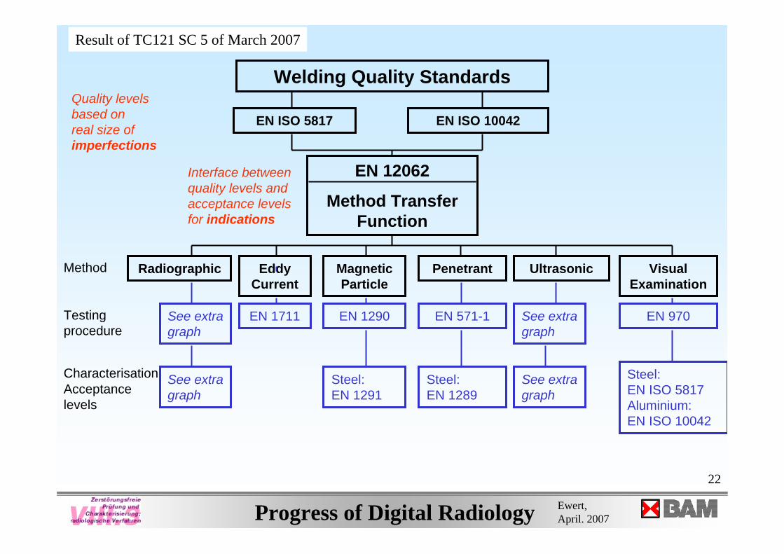
Welding Quality Standards
EN ISO 5817 EN ISO 10042
EN 12062
Method Transfer Function
Radiographic EddyCurrent
MagneticParticle
Penetrant Ultrasonic Visual Examination
EN 1711 EN 1290 EN 571-1 EN 970
CharacterisationAcceptancelevels
Steel:EN 1291
Steel:EN 1289
Steel:EN ISO 5817Aluminium:EN ISO 10042
See extragraph
See extragraph
Quality levels based onreal size of imperfections
Interface betweenquality levels andacceptance levelsfor indications
Method
Testingprocedure
See extragraph
See extragraph
Result of TC121 SC 5 of March 2007
23
Progress of Digital Radiology Ewert, April. 2007
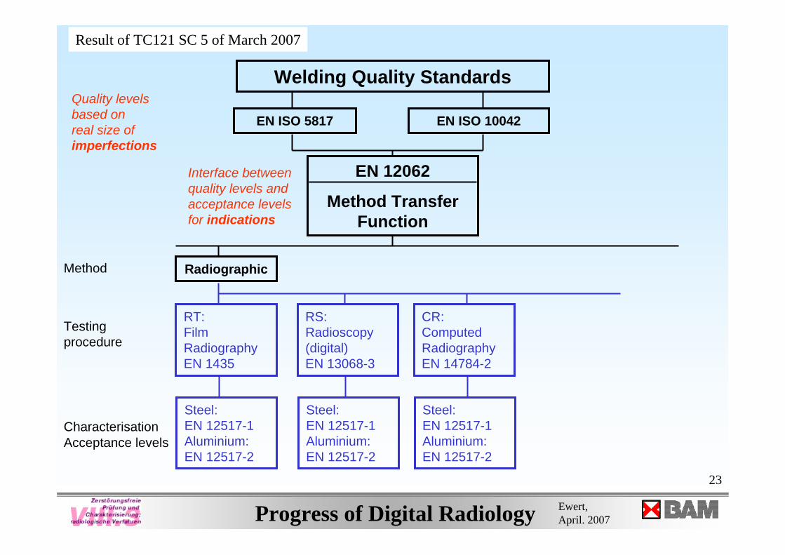
Radiographic
RT: FilmRadiographyEN 1435
RS: Radioscopy (digital)EN 13068-3
CR: Computed RadiographyEN 14784-2
Steel: EN 12517-1Aluminium:EN 12517-2
Steel: EN 12517-1Aluminium:EN 12517-2
Steel: EN 12517-1Aluminium:EN 12517-2
CharacterisationAcceptance levels
Method
Testingprocedure
Welding Quality Standards
EN ISO 5817 EN ISO 10042
EN 12062
Method Transfer Function
Quality levels based onreal size of imperfections
Interface betweenquality levels andacceptance levelsfor indications
Result of TC121 SC 5 of March 2007
24
Progress of Digital Radiology Ewert, April. 2007
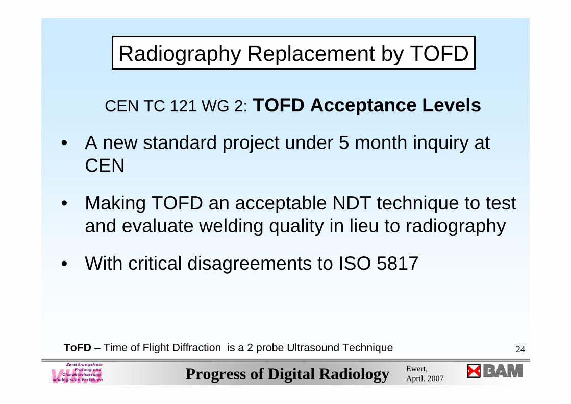
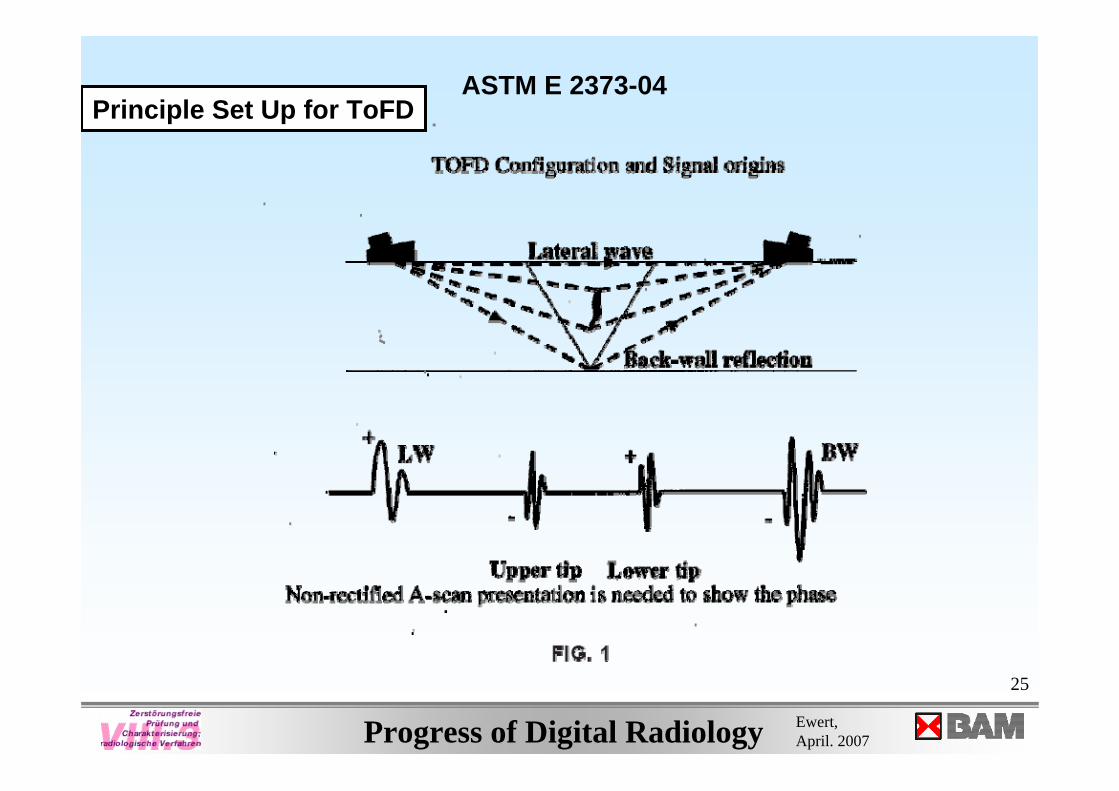
CEN TC 121 WG 2: TOFD Acceptance Levels
• A new standard project under 5 month inquiry at CEN
• Making TOFD an acceptable NDT technique to test and evaluate welding quality in lieu to radiography
• With critical disagreements to ISO 5817
ToFD – Time of Flight Diffraction is a 2 probe Ultrasound Technique
Radiography Replacement by TOFD
25
Progress of Digital Radiology Ewert, April. 2007
ASTM E 2373-04Principle Set Up for ToFD
26
Progress of Digital Radiology Ewert, April. 2007
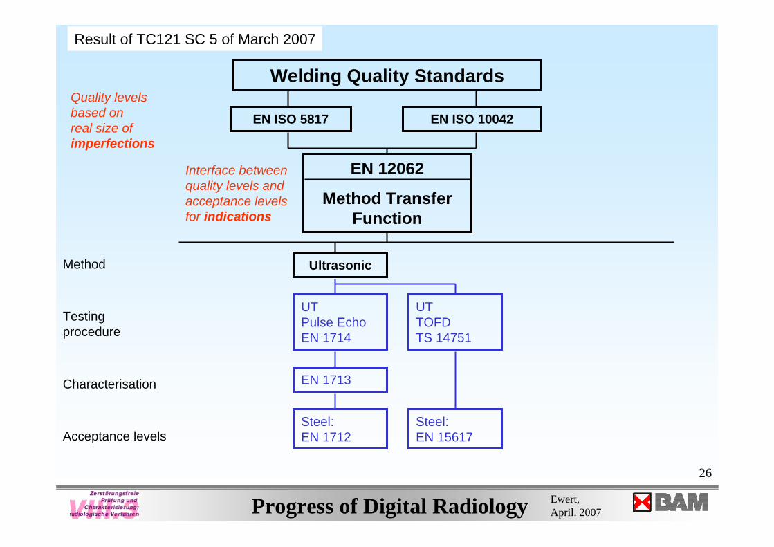
Ultrasonic
UT TOFDTS 14751
UT Pulse EchoEN 1714
EN 1713
Steel:EN 1712
Steel:EN 15617
Welding Quality Standards
EN ISO 5817 EN ISO 10042
EN 12062
Method Transfer Function
Quality levels based onreal size of imperfections
Interface betweenquality levels andacceptance levelsfor indications
Characterisation
Acceptance levels
Method
Testingprocedure
Result of TC121 SC 5 of March 2007
27
Progress of Digital Radiology Ewert, April. 2007
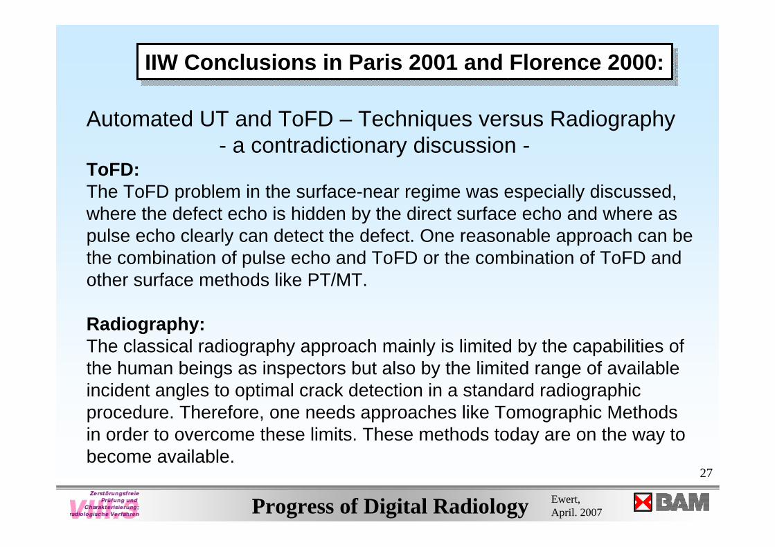
Automated UT and ToFD – Techniques versus Radiography- a contradictionary discussion -
ToFD:The ToFD problem in the surface-near regime was especially discussed, where the defect echo is hidden by the direct surface echo and where as pulse echo clearly can detect the defect. One reasonable approach can be the combination of pulse echo and ToFD or the combination of ToFD and other surface methods like PT/MT.
Radiography:The classical radiography approach mainly is limited by the capabilities of the human beings as inspectors but also by the limited range of available incident angles to optimal crack detection in a standard radiographic procedure. Therefore, one needs approaches like Tomographic Methods in order to overcome these limits. These methods today are on the way to become available.
IIW Conclusions in Paris 2001 and Florence 2000:IIW Conclusions in Paris 2001 and Florence 2000:
28
Progress of Digital Radiology Ewert, April. 2007
Ende
e-mail: [email protected]://www.bam.de
e-mail: [email protected]://www.bam.de
BAM-Berlin, Lab. VIII.3Unter den Eichen 8712005 BerlinTel. (030) 81041831FAX (030) 811 5089
BAM-Berlin, Lab. VIII.3Unter den Eichen 8712005 BerlinTel. (030) 81041831FAX (030) 811 5089
BAMmain building
29
Progress of Digital Radiology Ewert, April. 2007
Film Replacement
the Procedure
30
Progress of Digital Radiology Ewert, April. 2007
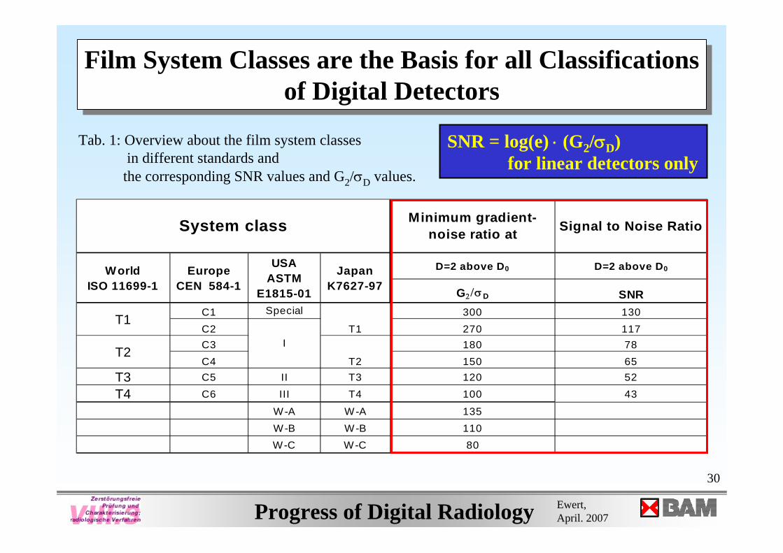
Film System Classes are the Basis for all Classificationsof Digital Detectors
Film System Classes are the Basis for all Classificationsof Digital Detectors
Tab. 1: Overview about the film system classes in different standards and
the corresponding SNR values and G2/σD values.
Minimum gradient-noise ratio at Signal to Noise Ratio
D=2 above D0 D=2 above D0
G2/σD SNRC1 Special 300 130C2 270 117C3 180 78C4 150 65
T3 C5 II T3 120 52
T4 C6 III T4 100 43
W-A W-A 135W-B W-B 110W-C W-C 80
T1
T2
System class
T1
T2
World ISO 11699-1
Europe CEN 584-1
USA ASTM
E1815-01
Japan K7627-97
I
SNR = log(e) ⋅ (G2/σD)for linear detectors only
31
Progress of Digital Radiology Ewert, April. 2007
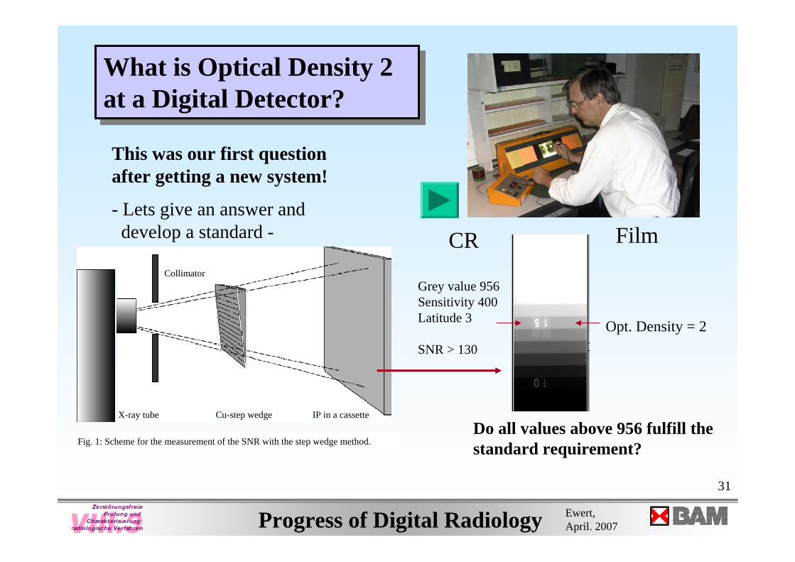
What is Optical Density 2 at a Digital Detector?What is Optical Density 2 at a Digital Detector?
Fig. 1: Scheme for the measurement of the SNR with the step wedge method.
X-ray tube Cu-step wedge IP in a cassette
Collimator
This was our first question after getting a new system!
- Lets give an answer anddevelop a standard - FilmCR
Opt. Density = 2
Grey value 956Sensitivity 400Latitude 3
SNR > 130
Do all values above 956 fulfill thestandard requirement?
32
Progress of Digital Radiology Ewert, April. 2007
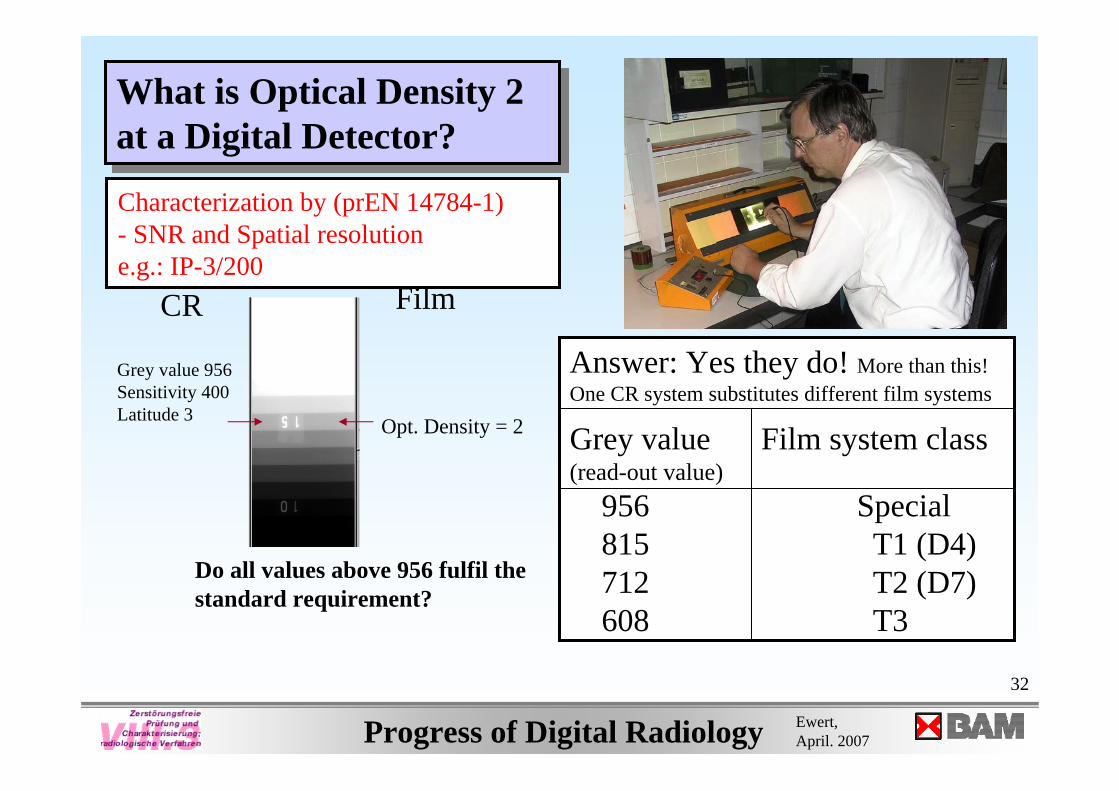
What is Optical Density 2 at a Digital Detector?What is Optical Density 2 at a Digital Detector?
FilmCR
Opt. Density = 2
Grey value 956Sensitivity 400Latitude 3
Do all values above 956 fulfil thestandard requirement?
Answer: Yes they do! More than this!One CR system substitutes different film systems
Grey value Film system class(read-out value)
956 Special815 T1 (D4)712 T2 (D7)608 T3
Characterization by (prEN 14784-1)- SNR and Spatial resolutione.g.: IP-3/200
33
Progress of Digital Radiology Ewert, April. 2007
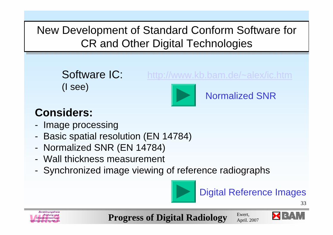
New Development of Standard Conform Software for CR and Other Digital Technologies
New Development of Standard Conform Software for CR and Other Digital Technologies
Software IC: http://www.kb.bam.de/~alex/ic.htm(I see)
Considers:- Image processing- Basic spatial resolution (EN 14784)- Normalized SNR (EN 14784)- Wall thickness measurement- Synchronized image viewing of reference radiographs
Normalized SNR
Digital Reference Images


![Index [msu.edu]Continuing education eWeRt HouSe, eWeRt PlACe, SuMMeRtoWn (off MAP) B1 Continuing education ReWley HouSe, 1 Wellington SquARe B5 Continuing Professional development](https://static.fdocuments.in/doc/165x107/5e718db0c7ad31345e781ee5/index-msuedu-continuing-education-ewert-house-ewert-place-summertown-off-map.jpg)


