![Trellis-Coded Modulation [TCM] - Educypediaeducypedia.karadimov.info/library/Trellis_Coded_Modulation.pdf · 1 Trellis-Coded Modulation [TCM] • Limitations of conventional block](https://static.fdocuments.in/doc/165x107/5a7932f17f8b9a07628d50a9/trellis-coded-modulation-tcm-trellis-coded-modulation-tcm-limitations.jpg)
Coded Modulation and Equalization for Wireless Infrared...
148
Coded Modulation and Equalization for Wireless Infrared Communications A THESIS Presented to The Academic Faculty By Hyuncheol Park In Partial Fullfillment of the Requirements for the Degree of Doctor of Philosophy in Elecrical Engineering School of Electrical and Computer Engineering Georgia Institute of Technology September, 1997 Copyright ©1997 by Hyuncheol Park
Transcript of Coded Modulation and Equalization for Wireless Infrared...

Coded Modulation and Equalization
for Wireless Infrared Communications
A THESIS
Presented to
The Academic Faculty
By Hyuncheol Park
In Partial Fullfillment
of the Requirements for the Degree of
Doctor of Philosophy in Elecrical Engineering
School of Electrical and Computer Engineering
Georgia Institute of Technology
September, 1997
Copyright ©1997 by Hyuncheol Park
Coded Modulation and Equalization
for Wireless Infrared Communications
Approved:
_i
Professor jJohn R. Bdrry, Chairman
J 2 _ _ ^ 2 __^
Professor Steven W. McLaughlin
s*/
Professor Gordon L. Stiiber
Date approved by Chairman

ii
Acknowledgments
I would like to thank to my mother, my wife Kyungeun, my son Junyong, my daughter
Jiwon, and my sister Hyunjoo for their encouragement, endurance, and sacrifice for my
late study. Without them, I would not have been where I am.
My great thanks go to professor John Barry. He has done an excellent job as a research
advisor, and I could not make a better choice. I sincerely appreciate for his advice, sugges
tions, and patience during the last four years which leads to this dissertation.
I would like to thank Professor Gordon Stiiber for serving as the chairman of my qual
ifying examination, and the reading committee of both my proposal and defense examina
tions. I also would like to thank Professor Steven McLaughlin for serving as the chairman
of my proposal examination, and the reading committee of my defense examination. I
appreciate Professor Douglas Williams and Professor Xingxing Yu for serving on my
defense examination committee.
I am thankful for my colleagues; Anuj Batra, Ricky Causey, and Chen-chu Yeh. Anuj
had been a my officemate for the first two years. I learned a lot from Ricky about the Star
Trek physics. In particular, Chen-chu has been a my officemate and lunchmate for the last
three years, and I really enjoyed the times that he shared with me.
Finally, I would like to thank to my Korean friends in communication and signal pro
cessing groups Jinsoup, Yongsub, Sangyoun, Ho, Jeongwook, and Dukhyun for their
encouragements.
Not that I have already obtained all this, or have already been made perfect, but I
press on to take hold of that for which Christ Jesus took hold of me (Philippians 3:12).

iii
Table of Contents
List of Tables vii
List of Figures viii
Summary xii
1 Introduction 1
1.1 WIRELESS INFRARED COMMUNICATIONS 2
1.2 MODELING OF WIRELESS INFRARED CHANNEL 5
1.3 THESIS OUTLINE 9
2 Performance of Modulation Schemes 11
2.1 POWER EFFICIENCY AND BANDWIDTH EFFICIENCY 12
2.1.1 Definitions 12
2.1.2 Pulse-position Modulation (PPM) 14
2.1.3 Multiple-Pulse Position Modulation (MPPM) 15
2.1.4 Overlapping Pulse-Position Modulation (OPPM) 18
2.1.5 Pulse Amplitude and Position Modulation (PAPM) 20
2.1.6 Discussions 22
2.2 ACCURATE BANDWIDTH CALCULATION 22
2.3 MPPM BOUND 26
2.4 SUMMARY AND CONCLUSIONS 27
3 Equalization 29
3.1 INTRODUCTION 29
iv
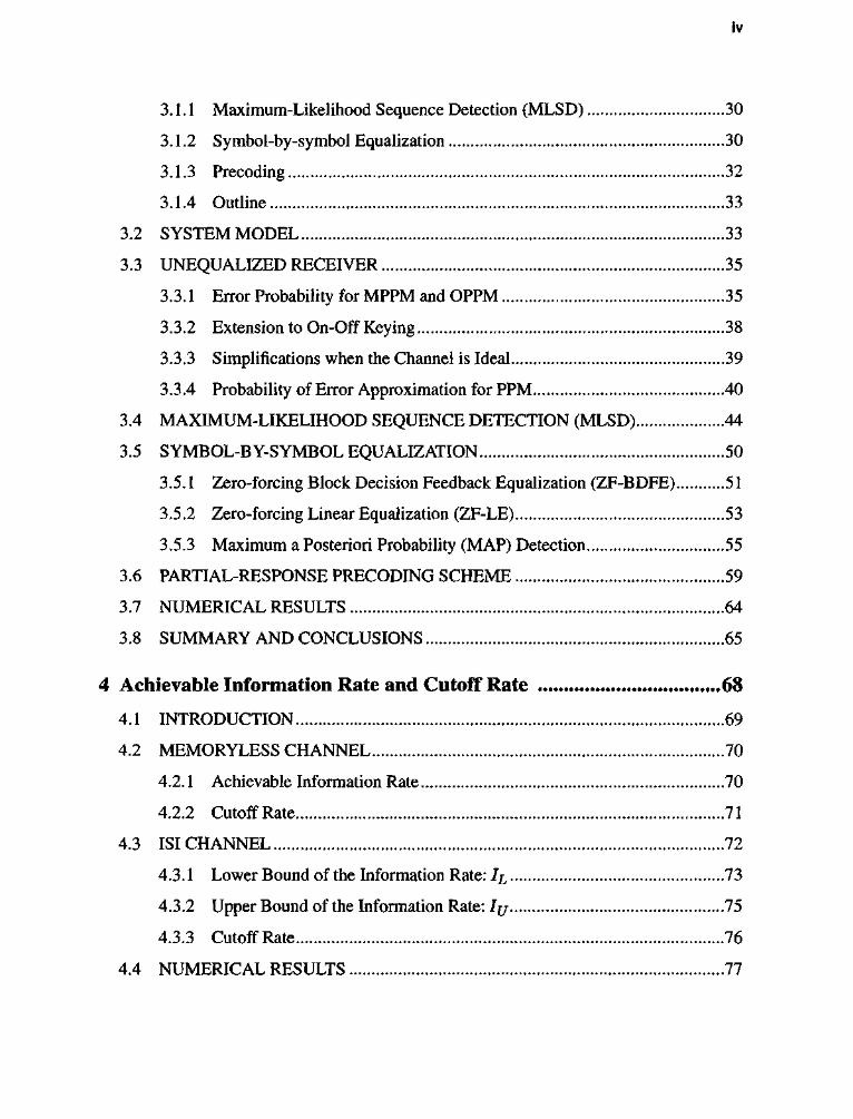
3.1.1 Maximum-Likelihood Sequence Detection (MLSD) 30
3.1.2 Symbol-by-symbol Equalization 30
3.1.3 Precoding 32
3.1.4 Outline 33
3.2 SYSTEM MODEL 33
3.3 UNEQUALIZED RECEIVER 35
3.3.1 Error Probability for MPPM and OPPM 35
3.3.2 Extension to On-Off Keying 38
3.3.3 Simplifications when the Channel is Ideal 39
3.3.4 Probability of Error Approximation for PPM 40
3.4 MAXIMUM-LIKELIHOOD SEQUENCE DETECTION (MLSD) 44
3.5 SYMBOL-BY-SYMBOL EQUALIZATION 50
3.5.1 Zero-forcing Block Decision Feedback Equalization (ZF-BDFE) 51
3.5.2 Zero-forcing Linear Equalization (ZF-LE) 53
3.5.3 Maximum a Posteriori Probability (MAP) Detection 55
3.6 PARTIAL-RESPONSE PRECODING SCHEME 59
3.7 NUMERICAL RESULTS 64
3.8 SUMMARY AND CONCLUSIONS 65
4 Achievable Information Rate and Cutoff Rate 68
4.1 INTRODUCTION 69
4.2 MEMORYLESS CHANNEL 70
4.2.1 Achievable Information Rate 70
4.2.2 Cutoff Rate 71
4.3 ISI CHANNEL 72
4.3.1 Lower Bound of the Information Rate: 1^ 73
4.3.2 Upper Bound of the Information Rate: IJJ 75
4.3.3 Cutoff Rate 76
4.4 NUMERICAL RESULTS 77

V
4.5 SUMMARY AND CONCLUSIONS 80
5 Coded Modulation 82
5.1 INTRODUCTION 82
5.2 CONVOLUTIONAL CODED PPM 85
5.2.1 Rate l/log2L Convolutional Coded L-PPM 85
5.2.2 Rate (log2L - l)/log2L Convolutional Coded L-PPM 87
5.3 TRELLIS CODED OPPM 91
5.4 TRELLIS CODED MPPM 93
5.4.1 Design of Trellis Coded MPPM 94
5.4.2 An Approximation for the dmin of Trellis Coded MPPM 101
5.5 PERFORMANCE OF CODED MODULATION SCHEMES 102
5.6 SUMMARY AND CONCLUSION 104
6 Coded Modulation on a Multipath Channel 105
6.1 INTRODUCTION 105
6.2 SYSTEM MODEL 108
6.3 SUPERSTATE MLSD 109
6.4 PARALLEL DECISION FEEDBACK DETECTION (PDFD) 111
6.5 PRECODING I l l
6.6 NUMERICAL RESULTS 113
6.7 SUMMARY AND CONCLUSIONS 116
7 Conclusions and Future Work 118
7.1 CONCLUSIONS 118
7.2 FUTURE WORK 120
7.2.1 Channel Capacity of Wireless Infrared Channel 120
7.2.2 Concatenated Codes 122
7.2.3 Turbo Codes 124
7.2.4 Synchronization 124

vi
7.2.5 System Implementation 126
References 127
Vita 135
vii
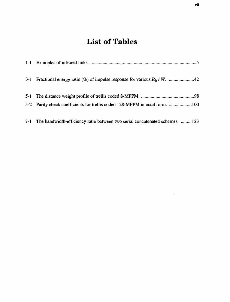
List of Tables
1-1 Examples of infrared links 5
3-1 Fractional energy ratio (%) of impulse response for various Rb/W 42
5-1 The distance weight profile of trellis coded 8-MPPM 98
5-2 Parity check coefficients for trellis coded 128-MPPM in octal form 100
7-1 The bandwidth-efficiency ratio between two serial concatenated schemes 123

VIII
List of Figures
1-1 Two most typical wireless infrared links, (a) Directed, LOS link,
(b) Nondirected, non-LOS, or diffuse link 3
1-2 (a) Transmission and reception in an infrared link with intensity modulation
and direct detection, (b) modeling link as a baseband linear, time-invariant
system having impulse response h{t) with additive noise n(t) 6
2-1 Four pulse-position modulation (PPM) 14
2-2 The (2) multiple-pulse position modulation 16
2-3 Choose overlapping pulse-position modulation (OPPM) codewords from
MPPM codewords 19
2-4 The 2-4-pulse amplitude and position modulation 21
2-5 Power and bandwidth efficiency of uncoded modulation schemes on an
ideal channel 23
2-6 Power spectral density of modulation schemes (a) PPM, (b) MPPM, (c) OPPM. ..25
2-7 Binary entropy function 27
2-8 Power efficiency and bandwidth efficiency of (£)-MPPM and MPPM bound 28
3-1 (a) Block diagram of MPPM system, (b) equivalent vector channel 33
3-2 Decision device for the unequalized receiver 36
3-3 Gaussian approximation method and the exact method
for the unequalized receiver 43
3-4 The required power versus bit rate on an ISI channel (a) unequalized system,
(b)withMLSD 48
3-5 Power efficiency versus bandwidth efficiency of PPM over ISI channel 49
ix
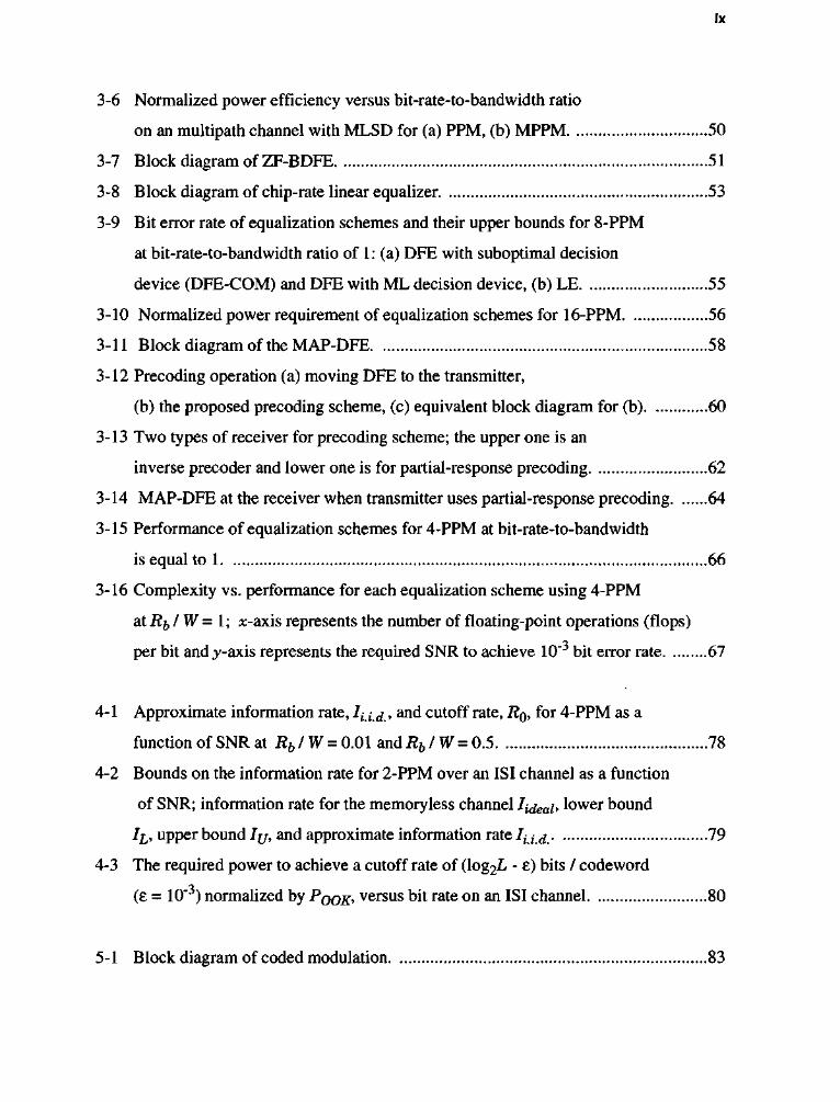
3-6 Normalized power efficiency versus bit-rate-to-bandwidth ratio
on an multipath channel with MLSD for (a) PPM, (b) MPPM 50
3-7 Block diagram of ZF-BDFE 51
3-8 Block diagram of chip-rate linear equalizer 53
3-9 Bit error rate of equalization schemes and their upper bounds for 8-PPM
at bit-rate-to-bandwidth ratio of 1: (a) DFE with suboptimal decision
device (DFE-COM) and DFE with ML decision device, (b) LE 55
3-10 Normalized power requirement of equalization schemes for 16-PPM 56
3-11 Block diagram of the MAP-DFE 58
3-12 Precoding operation (a) moving DFE to the transmitter,
(b) the proposed precoding scheme, (c) equivalent block diagram for (b) 60
3-13 Two types of receiver for precoding scheme; the upper one is an
inverse precoder and lower one is for partial-response precoding 62
3-14 MAP-DFE at the receiver when transmitter uses partial-response precoding 64
3-15 Performance of equalization schemes for 4-PPM at bit-rate-to-bandwidth
is equal to 1 66
3-16 Complexity vs. performance for each equalization scheme using 4-PPM
at Rfj IW = 1; x-axis represents the number of floating-point operations (flops)
per bit andy-axis represents the required SNR to achieve 10"3 bit error rate 67
4-1 Approximate information rate, Iumd.> anc* cutoff rate, R0, for 4-PPM as a
function of SNR at Rb/W = 0.01 andRb/W = 0.5 78
4-2 Bounds on the information rate for 2-PPM over an ISI channel as a function
of SNR; information rate for the memoryless channel lideab lower bound
Il, upper bound IUy and approximate information rate lad. 79
4-3 The required power to achieve a cutoff rate of (log2L - £) bits / codeword
(£ = 10"3) normalized by POOK> versus bit rate on an ISI channel 80
5-1 Block diagram of coded modulation 83

X
5-2 A convolutional coded 4-PPM and its trellis 86
5-3 An error event with Hamming distance 2(v + 1) 87
5-4 The calculated minimum distance (denoted by circles) of convolutional
coded PPM with its upper bounds (5-2) and (5-7) (denoted by solid line),
and simplex bound (5-8) (denoted by dashed line) 90
5-5 Convolutional coded 16-PPM with cutoff rate bound 91
5-6 The 8-OPPM signal set and its set partitioning 94
5-7 Constellations for ( \ )-MPPM; the shaded circles represent the chosen L
codewords and unshaded circles represent the unused codewords.
The x-axis represents the position of first pulse and the y-axis represents
the position of second pulse, (a) L = 8 and n = 5, (b) L = 16 and n = 7,
(c) L = 32 and n = 9, (d) L = 64 and n = 13, (e) L = 128 and n = 17 95
5-8 Set partitioning of 8-MPPM 97
5-9 Systematic feedback encoder for trellis coded 128-MPPM with constraint
length v and parity check coefficients hmn, m= 1,2, . . . , v - l
and n = 0, 1, ..., 6 99
5-10 Power efficiency and bandwidth efficiency of coded modulation 103
6-1 Block diagram of coded modulation on an ISI channel 109
6-2 Block diagram of DFE with tentative decision and MLSD 112
6-3 Power penalties of trellis coded 128-MPPM vs. trellis coded 16-PPM 114
6-4 Performance of equalizer for the convolutional coded 8-PPM at i ^ / W = 1 115
6-5 Performance of equalizer for the trellis coded 128-PPM atRb/W=\ 116
6-6 Complexity vs. performance for each equalization scheme using
convolutional coded 8-PPM ar Rb IW = 1; x-axis represents the number of
floating-point operations per bit and y-axis represents the required SNR to achieve
10"3 bit error rate 117
7-1 Serial concatenated codes: (a) convolutional coded PPM,

xi
(b) PPM with convolutional code, (c) a systematic feedforward convolutional
encoder for configuration (b) 122
7-2 Effects of timing error for OOK when (a) current bit = 0 and next bit = 0,
(b) current bit = 0 and next bit = 1, (c) current bit = 1 and next bit = 0,
(d) current bit = 1 and next bit = 1 125

XII
Summary
The channel model for wireless infrared communication is unique: it combines the
intensity-modulation constraints of the Poisson photon-counting channel with the multi-
path dispersion, limited bandwidth, and Gaussian noise of the conventional radio channel.
The objective of this thesis is to develop and analyze new power-efficient modulation,
coding, and equalization schemes that are well-suited to the wireless infrared channel. Our
strategy is to combine new trellis codes with precoding, so that the coding gain of the
trellis code is obtained in combination with the equalization performance of a decision-
feedback equalizer.
We investigate the performance of several candidate uncoded modulation techniques
in terms of error probability, bandwidth expansion, information rate, cutoff rate, and sensi
tivity to multipath dispersion. To mitigate intersymbol interference, we propose a partial-
response precoding scheme that is compatible with the infrared channel. For each modula
tion scheme, we compare the performance of symbol-by-symbol equalizers such as the
linear equalizer, the decision feedback equalizer, the maximum a posterior detector, and
the proposed precoder to the optimum maximum-likelihood sequence detector.
We design new trellis codes based on multiple pulse-position modulation that offer
high power efficiency. We randomly search for the optimal code that produces the trellis
code with the largest minimum Euclidean distance. To verify our results, we derive an
approximation for minimum distance. We combine partial-response precoding with par
allel decision-feedback detection to equalize and to decode the trellis codes. The perfor
mance of the proposed scheme is compared to linear equalization, decision feedback
equalization, parallel decision-feedback detection, and super-state maximum-likelihood
sequence detection. Together, the proposed trellis codes and precoding schemes are an
effective solution to the signaling design problem, especially in the face of severe multi-
path dispersion.

CHAPTER 1
I N T R O D U C T I O N
The rapid growth of the laptop and handheld computer industries has elevated the
importance of indoor wireless communications and wireless local area networks. There
are several options for the transmission medium in indoor wireless communication: radio
wave, microwave, millimeter wave, and infrared radiation. In both research and commer
cial products, radio and microwave with frequencies less than 30 GHz are the most com
monly used. Millimeter wave (30 ~ 300 GHz) lies between the microwave and far infrared
region. There is currently an interest in the millimeter wave near 60 GHz because of its
high attenuation due to oxygen absorption. This frequency band is useful for applications
requiring a high attenuation beyond the normal service area to reduce co-channel interfer
ence [1]. However, devices operating at this frequency are still very expensive.

2
An attractive alternative is infrared radiation with wavelengths in the 750-1000 nm
range. As a medium for indoor wireless networks, nondirected infrared radiation offers
several advantages over radio, microwave, and millimeter wave as follows:
• Infrared offers an immense window of unregulated bandwidth. On the con
trary, the spectral regions for radio, microwave, and millimeter wave are
strictly regulated to use and almost scarce.
• Infrared radiation cannot penetrate walls and the transmitted signal remains
in the same room where it originates. This prevents eavesdropping and
interferences from neighboring rooms. (But, the signal confinement in a
room is also a drawback since it limits the range covered).
• The dimension of infrared detector is much larger than the operating wave
length. This leads to an equivalent spatial diversity which prevents the mul
tipath fading.
1.1 WIRELESS INFRARED COMMUNICATIONS
At present, most infrared links are directed, line-of-sight (LOS) transmission in the
850-950 nm range as shown in Fig. 1-1-a. In directed, LOS links, a directional transmitter
and receiver are used and must be aimed to establish a link. This type of link depends on
the existence of a LOS path between the transmitter and receiver to maximize the power
efficiency and to minimize multipath distortion. For example, JOLT announced a 125 Mb/
s LOS system that employs a 1° transmitter beam and a 6° receiver field of view. British
Telecommunication Laboratory reported a 155 Mb/s directed, LOS link using on-off
keying (OOK) [2]. In 1993, a consortia of over 150 companies formed the Infrared Data
Association (IrDA) to set and to support hardware and software standards that create
infrared communication links [3]. IrDA developed the standard for short range, low cost,

3
and low power LOS links operating at a bit rate of 4 Mb/s using 4 pulse-position modula
tion (PPM). In 1995, Microsoft announced support for IrDA connectivity to Windows'95,
enabling wireless connectivity between Windows'95 based PCs and peripheral devices.
IrDA-compliant IR ports are now an integral feature of most laptop computers, printers,
and electronic organizers, and they will be incorporated into cellular phones, pagers,
watches, and automatic teller machine [4].
Consider next the nondirected, non-LOS, or diffuse configuration as shown in Fig. 1-1-
b. In a diffuse link, the transmitter and receiver are not aligned, and the link design does
not depend on the LOS path, but depends on reflections from ceiling, walls, and other
reflectors. A diffuse link is the most convenient and easy-to-use, but it has a higher path
loss than the LOS configuration. For example, Spectrix Corporation has developed a 4
ftX.KX.X.X.X.X.X.X.-X^
Transmitter x X
lix IIK iix I IX 1 X I IX l l X
X X X K X X X X X X X X
' y y y y y y y y y y y y y y y y y y y y g y y y y y y y y y y y y y y y y y y y y v r
Receiver!
(a) (b)
Fig. 1-1. Two most typical wireless infrared links, (a) Directed, LOS link (b) Nondirected, non-LOS, or diffuse link [9].

4
Mb/s wireless LAN employing OOK with an operating range of 15 m [5]. This configura
tion is designed to communicate between a portable transceiver and a host computer in
large open areas such as offices, factories, or the trading floors of stock markets. Photonics
and IBM developed a diffuse infrared ad hoc LAN operating at 1 Mb/s using 16-PPM
within a 10 m room. This type of link is employed to achieve direct, peer-to-peer commu
nication between a number of portables and fixed terminals. Finally, the performance of a
50 Mb/s diffuse link using OOK was demonstrated by an experiment at UC Berkeley [6].
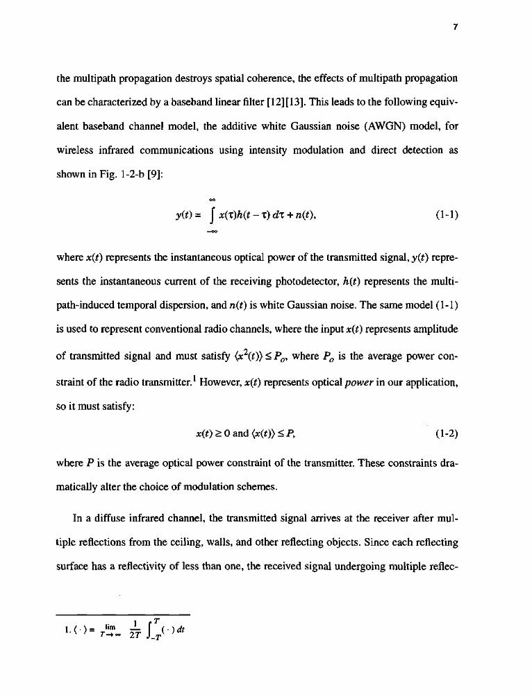
Table 1-1 summarizes the key features of several infrared links. All systems listed, except
the first prototype by IBM, use OOK or pulse-position modulation (PPM). Compared to
the diffuse links, the directed, LOS links achieve higher data rates.
Since Gfeller and Bapst's pioneering work [7] in diffuse infrared communication in
1979, there has been a growth in research activity and product development in this area.
Kotzin [8] described the design of an experimental prototype for a portable telephone
system. Barry made contributions in modulation analysis [9], channel modeling [10], and
link design [11]. Since 1994, Kahn and his students at UC Berkeley have made numerous
contributions, including experimental characterization of the nondirected indoor infrared
channel [12] [13], performance evaluation of modulation, coding, and equalization based
on measured channels [ 141[ 15][ 16J[ 17], and channel reuse strategies. Kavehrad and his
students [18] at the University of Ottawa have worked on the measurement of the channel
frequency response, the design of a diffuser, and diversity techniques. Researchers at
Aveiro University [19] have worked on modeling and simulation for the indoor infrared
channel.
5
TABLE 1-1: Examples of infrared links.
Affiliation Year Type Modulation Bit rate
IBM 1979 diffuse BPSK 125 Kb/s
ATS 1985 directed, LOS OOK lOMb/s
Spectrix 1987 diffuse OOK 4Mb/s
IrDA 1993 directed, LOS 4-PPM 4Mb/s
IBM/Photonics 1993 diffuse 16-PPM IMb/s
Apple 1994 directed, LOS OOK 38.4 Kb/s
UC Berkeley 1994 diffuse OOK 50 Mb/s
BTLab 1994 directed, LOS OOK 155 Mb/s
1.2 MODELING OF WIRELESS INFRARED CHANNEL
In a wireless optical system, the most practical modulation technique is intensity mod
ulation, in which the information modulates the instantaneous power of the carrier. The
most practical detection technique is direct detection, in which a photodetector produces a
current proportional to the received instantaneous power. The model of the infrared
channel with intensity modulation / direct detection (IM / DD) is illustrated in Fig. 1-2
[11]. The transmitted signal x(t) is the instantaneous optical power of the infrared trans
mitter. The received signal y(t) is the instantaneous current in the receiving photodetector,
which is proportional to the integral of received optical power over the photodetector sur
face.
The appropriate channel model for wireless optical communications systems using IM
/ DD depends on the intensity of the background light. In low background light, it is
common to model the received signal as a Poisson process with rate \s(t) + Xn, where

6
Xs(t) is proportional to the instantaneous optical power of the received signal, and Xn is
proportional to the power of the background light. When Xn is zero, the channel is
quantum limited. However, the background light in typical indoor environments is very
intense; even after a narrow-band (10 nm) optical filter, Xn will be between 1011 and 10
photons/s, depending on the proximity to a window [7]. Therefore, the photodetector shot
noise is accurately modeled as an additive white Gaussian noise (AWGN) plus a d.c. offset
[20]. Also, as illustrated in Fig. 1-2, typical detector areas are millions of square wave
lengths, leading to spatial diversity that prevents multipath fading. Furthermore, because
Input Current ¥
LED or L D / Optical
Power x(t)
Photodetector
Photocurrent
(a)
1
• © • ? ( ' )
AWGN n(t)
x(t) • hit)
1
• © • ? ( ' )
AWGN n(t)
x(t) > 0 <x(t)><P
1
• © • ? ( ' )
AWGN n(t)
(b)
Fig. 1-2. (a) Transmission and reception in an infrared link with intensity modulation and direct detection, (b) modeling link as a baseband linear, time-invariant system having impulse response hit) with additive noise nit). [11]
7
the multipath propagation destroys spatial coherence, the effects of multipath propagation
can be characterized by a baseband linear filter [12] [13]. This leads to the following equiv
alent baseband channel model, the additive white Gaussian noise (AWGN) model, for
wireless infrared communications using intensity modulation and direct detection as
shown in Fig. 1-2-b [9]:
oo
y(t)= J x{%)h{t - T) dl + n(t), (1-1) —oo
where x(t) represents die instantaneous optical power of the transmitted signal, y(t) repre
sents the instantaneous current of the receiving photodetector, h(t) represents the multi-
path-induced temporal dispersion, and n{t) is white Gaussian noise. The same model (1-1)
is used to represent conventional radio channels, where the input x{i) represents amplitude
of transmitted signal and must satisfy (x2(t)) < P0, where P0 is the average power con
straint of the radio transmitter.1 However, x{t) represents optical power in our application,
so it must satisfy:
x(t) > 0 and (x(t)) <P, (1 -2)
where P is the average optical power constraint of the transmitter. These constraints dra
matically alter the choice of modulation schemes.
In a diffuse infrared channel, the transmitted signal arrives at the receiver after mul
tiple reflections from the ceiling, walls, and other reflecting objects. Since each reflecting
surface has a reflectivity of less than one, the received signal undergoing multiple reflec-
••<•>• r'T- 2 ? J > > < *

8
tions has a smaller power than that of the transmitted signal. A natural model for the
impulse response of the multipath channel is an exponential decay:
h(t) = We-Wtu(t), (1-3)
where W is the 3-dB bandwidth and u(t) is unit-step function. Note that the channel has
unity D.C gain. Carruthers et al. [13] derived the ceiling-bounce model for the wireless
infrared channel. In the ceiling-bounce model, the impulse response due to diffuse reflec
tion from a single infinite-plane reflector such as a large ceiling is:
h(t)=-^—u(t), (1-4) (t + a)
where a = 2HI c, H is the height of the ceiling above the transmitter and the receiver, and
c is the speed of light. Compared to (1-3), (1-4) provides a slightly better fit to the mea
sured channel [13]. But, ceiling-bounce model assumes the transmitter and receiver are
colocated. The exponential decay model is more general because it does not depend on the
geometry of transmitter and receiver, and is characterized by one parameter, W. For
example, the measured value of W for an empty conference room having dimension (7.5
m x 5.5 m x 3.5 m) is 34 MHz [9]. Hence, we will use this model from here on.
The unique characteristics of this channel model have motivated recent research in
search of power-efficient and bandwidth-efficient modulation and coding techniques that
are well-suited to the channel [4][6][8][9][14]-[17][21][28][30][63]. Many of the conven
tional digital communication results do not hold for this channel. For example, quadrature
amplitude modulation (QAM), which is frequently used in conventional channels, is not
suitable for the diffuse infrared channel because of its poor power efficiency. Similarly,

9
coded modulation schemes designed for the conventional channel may not perform well
on the infrared channel. Instead, as will be shown in chapter 2, the constraint (1-2) favors
modulation schemes with low duty cycle, such as pulse-position modulation.
1.3 THESIS OUTLINE
The goal of this thesis is to develop and analyze new power-efficient modulation,
coding, and equalization schemes that are compatible with the infrared channel.
In chapter 2, we try to find some efficient uncoded modulation schemes on an ideal
channel. First, we compare the performance of several candidate uncoded modulation
techniques by calculating the required bandwidth and the average optical power required
at a given bit rate to achieve a desired bit error rate. We also calculate the exact bandwidth
of each modulation scheme from its power spectrum density. We derive a bound for the
power and bandwidth efficiency of multiple-pulse position modulation.
In chapter 3, we take into account intersymbol interference (ISI) due to the multipath
distortion. We compare the performance of several equalization techniques for the
uncoded modulation schemes considered in chapter 2. First, we derive a vector channel
model for MPPM on an ISI channel. We calculate the exact error probability when the
receiver does not use equalization, and derive the Gaussian approximation for the special
case of PPM. We then derive an upper bound for the error probability of the optimum
maximum-likelihood sequence detection (MLSD) over a vector channel. To mitigate the
effect of ISI with reduced complexity, we propose a partial-response precoding scheme
and compare it with several symbol-by-symbol equalization schemes, including zero-
10
forcing block decision feedback equalization (ZF-BDFE), zero-forcing linear equalization
(ZF-LE), and maximum a posteriori (MAP) detection.
In chapter 4, we consider the achievable information rate and cutoff rate for modula
tion schemes as a limit of performance. We present expressions for these parameters on an
ideal channel when the input codewords are independent, identically uniform-distributed.
We then derive lower and upper bounds for the information rate over an ISI channel. We
also calculate the required optical power to achieve a specific cutoff rate.
In chapter 5, we design a new trellis codes so as to improve the overall power effi
ciency. First, we consider convolutional coded PPM and derive an upper bound for the
minimum Euclidean distance. We then present an expression for the coding gain of trellis
coded OPPM. Finally, we present the design procedure and computer search results for
new trellis codes based on MPPM. We derive an approximation for the minimum
Euclidean distance of trellis coded MPPM and compare it to the well-known simplex
bound.
In chapter 6, we evaluate the performance of the coded modulation schemes developed
in chapter 5 on a multipath channel by employing superstate MLSD, LE with MLSD, DFE
with MLSD, parallel decision feedback detection (PDFD), and the proposed precoding
scheme with PDFD.
In chapter 7, we conclude our study with some interesting topics for future research.
CHAPTER 2
P E R F O R M A N C E O F M O D U L A T I O N S C H E M E S
As we indicated in section 1.2, conventional modulation schemes do not work well
under the constraints (1-1) and (1-2). As we will see, the probability of error depends on
x(t) rather than x(t), and a signal set whose peak-power-to-average-power ratio is large
offers better performance in terms of power efficiency. Therefore, in this chapter we con
centrate on modulation schemes having a low duty-cycle. Most modulation schemes we
consider here have been used for the photon-counting channel. However, due to the unique
nature of the diffuse infrared channel, we cannot apply the results of photon-counting
channel to our case directly.

12
In section 2.1, we calculate the power efficiency and bandwidth efficiency of several
uncoded modulation schemes. In 2.2, we calculate the accurate bandwidth of each modu
lation scheme by calculating the power spectrum density. In 2.3, we derive the MPPM
bound as a limit of performance of MPPM when the codeword length is arbitrarily large.
2.1 POWER EFFICIENCY AND BANDWIDTH EFFICIENCY
When we evaluate the performance of modulation schemes, the two most important
criteria are power efficiency and bandwidth efficiency. The power efficiency corresponds
to the required power to achieve a specific bit error rate, and the bandwidth efficiency cor
responds to the bandwidth occupied to achieve a specific bit rate. In this section, we intro
duce several candidate modulation schemes and compare these schemes based on the two
criteria.
2.1.1 Definitions
We first review the classic problem of determining the error probability for an L-ary
modulation scheme in the presence of additive white Gaussian noise, assuming maximum-
likelihood (ML) detection, and neglecting intersymbol interference [22][23]. The trans
mitter conveys information at a rate of ify, bits/second by transmitting one of L nonnega-
tive signals {x-^it), tf2(*)> ••• yXL{t)} every T = log2L/ify, seconds, and the channel adds
white Gaussian noise with power spectrum N0. To prevent intersymbol interference, each
signal is confined to the interval [0, T). The signal set satisfies (1-2) with equality, so that
the average signal power is •=• fLfeft)) = P. For example, an on-off-keying (OOK) trans-Ld
mitter emits a rectangular pulse of duration 1 /R^ and of intensity IP to signify a one bit,
13
and no pulse to signify a zero bit. The bandwidth required by OOK is roughly Rb, the
inverse of the pulse width.
To simplify analysis, we make the high-SNR assumption that the probability of bit
error is dominated by the two nearest signals, so that:
Pr[bit error] » Q(dmin/2 JN~Q\ (2-1)
where dmin is the minimum Euclidean distance between any pair of valid signals:
dlun = T \(xi(t)-Xj(t))2dt. (2-2)
In fact, (2-1) is exact for OOK (and any time L = 2); the minimum distance between the
two signals in the OOK signal set is:
2P dOOK = -f=» (2-3) *JRb
and the probability of bit error, assuming ML detection, is
Pr[bit error] = Q ( p ^
.W (2-4)
bJ
We will use OOK as a benchmark to compare the power efficiencies of various modu
lation schemes. The power required by OOK to achieve a given bit error rate (BER) is
POOK = jNQRb Q'^iBER). The power required by any other modulation scheme to
achieve the same BER is approximately P - (dgQK/dmin)PQQK, assuming the SNR is
high enough that (2-1) is accurate. Therefore, in the remainder of the chapter we will use
the distance ratio dQ0K/dmin to characterize the power requirement of any modulation
scheme.
14
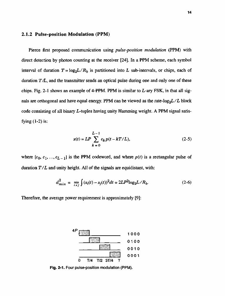
2.1.2 Pulse-position Modulation (PPM)
Pierce first proposed communication using pulse-position modulation (PPM) with
direct detection by photon counting at the receiver [24]. In a PPM scheme, each symbol
interval of duration T = \og2L/Rb is partitioned into L sub-intervals, or chips, each of
duration T/L, and the transmitter sends an optical pulse during one and only one of these
chips. Fig. 2-1 shows an example of 4-PPM. PPM is similar to L-ary FSK, in that all sig
nals are orthogonal and have equal energy. PPM can be viewed as the rate-log2L/L block
code consisting of all binary L-tuples having unity Hamming weight. A PPM signal satis
fying (1-2) is:
L - i
x(t) = LP ]T ckp(t-kT/L), (2-5) k = o
where [c0, cl5 ...,C£_;J is the PPM codeword, and where p(t) is a rectangular pulse of
duration T/L and unity height. All of the signals are equidistant, with:
dliin = Z1) J (*/(*) - *j(t))2dt = 2LP2\og2L/Rb. (2-6)
Therefore, the average power requirement is approximately [9]:
4P 1 0 0 0
01 0 0
0 0 1 0
0 0 0 1 0 T/4 T/2 3T/4 T
Fig. 2-1. Four pulse-position modulation (PPM).
15
PpPM/POOK~d00K/dmin= lj-^—£. (2-7)
From (2-7) we see that, for any L greater than 2, PPM requires less optical power than
OOK. In principle, the optical power requirement can be made arbitrarily small by making
L suitably large, at the expense of increased bandwidth; the bandwidth required by PPM to
achieve a bit rate of Rb is approximately the inverse of one chip duration,
B = L/T = LRb/log2L:
flpPM/tf6=_. (2-8)
2.1.3 Multiple-Pulse Position Modulation (MPPM)
One generalization of PPM is multiple-pulse position modulation (MPPM), suggested
by Sugiyama and Nosu [25]. In MPPM, each symbol interval of duration T = \og2L/Rb is
partitioned into n chips, each of duration T/ n, and the transmitter sends an optical pulse
during w of these chips. Fig. 2-2 shows an example of (2)-MPPM. The transmitted signal
is given by:
7 1 - 1
x(t) = a £ ckty(t-kT/n), (2-9) k = 0
where [c0, c1?..., cn _ J is a binary rc-tuple of weight w, where <j)(0 = Jn/T pit) is a unit-
energy rectangular pulse of duration T/n, and where the constant a is chosen so that the
average optical power is P: a = (P/w) Jnf = d00K Jn^°Ei^ /^w- T n e r e are (J) binary
rc-tuples of weight w, but it may be desirable to use only a fraction L of these; for example,

16
we may choose the codewords to have a large minimum Hamming distance d. That is, we
may restrict attention to an (n, d, w) constant weight code [26] [27], which is a set of
binary n-tuples having weight w and minimum Hamming distance d.
For a given n, d, and w, let L < (£) be the number of valid codewords. We must have
d>2, because it is impossible for two binary n-tuples of weight w to differ in only one
position. If we admit all binary n-tuples of weight w, then L = (£,) and d = 2. The band
width is roughly n/T, the inverse of the chip duration, so that [28]:
B MPPM' ^b /RK = n log2L'
(2-10)
Because {§(t - kT/n)} is an orthonormal set, (2-9) implies that the Euclidean distance
between any two MPPM waveforms xfi) and Xj(t) is a Jd^-, where d^ is the Hamming
distance between the corresponding binary n-tuples. Thus, the minimum distance is
dmin -ajd, where d is the minimum Hamming distance and a - doog Jn\og2L /2w.
The ratio of doo% to dmin gives the average power requirement:
PMPPM/POOK = 1w
Jnd\og2L (2-11)
2P 1 1 00
1010
1 001
0 1 1 0
0 1 0 1
001 1 T/4 T/2 3T/4 T
Fig. 2-2. The (2) multiple-pulse position modulation.

17
Note that PPM is a special case of MPPM with n=L,d = 2, and w = 1, and that (2-
11) reduces to (2-7) in this case.
(2,)-MPPM can be viewed as a binary permutation modulation, introduced by Slepian
[29]. All codewords are generated by permuting the initial vector CQ, which can be repre
sented in general form:
c0 = i 000...0 111... 1 f. (2-12) v v v '
n-w w
The other codewords are obtained by permuting the order in all possible ways, and the
number of codewords is:
L = (n)= * ! „ . (2-13) [wj w\(n-w)\
Since all codewords have the same length and weight, they lie on a sphere with a radius of
square-root of signal energy. For example, (^-MPPM codewords can be obtained by per
muting the initial codeword c0 = [001 l]T:
{[OOlltf [OlOlf, [OllOf, [100lf, [1010]rf [llOOf}. (2-14)
The receiver on an ideal channel decides on the codeword cj that maximizes the corre
lation [29][30]:
Al = eiTyk forZ = 0, . . . , L - l . (2-15)
Note that PPM is also a permutation modulation with w = 1.
Permutation modulation is a special case of a group code [31]. A code is defined as a
group code if its codewords are generated by multiplication of an initial vector c0 with
nxn orthogonal matrices Oh 02,..., Og, and this collection of matrices forms a group F
18
under matrix multiplication. In other words, there is a member in V that will map any
given codeword c; into any other codeword cy In general, the order g of the group is
greater than the number of codewords, M, andg = n\ for a permutation modulation.
A group code is a set of vectors with complete symmetry, that is, all codewords have
(a) the same error probability, (b) the same set of distances to the other codewords, and (c)
the same energy. In general, the error probability of MPPM is given by [30] (see
section 3.3.3):
Pr[error] < £ NkQ k = l
ks '2 AT V
(2-16)
where N^ = Ck)(nkw) is the number of codewords with mutual distance 2k and
s = (P/w)Jn\og2L/Rb . Note that MPPM satisfies all the properties of a group code.
PPM is also a cyclic group code because group T is the set of matrices whose elements
are the powers of a generator matrix O. In other words, codewords are obtained by:
Ci = Olc0 fori = 0, 1, ...,L~ 1, (2-17)
where O =
0 0 ... 0 1 1 0 ... 0 0
0 0 ... 1 0
2.1.4 Overlapping Pulse-Position Modulation (OPPM)
We define (£) overlapping pulse-position modulation (OPPM) code as a subset of
MPPM code, where the w ones are constrained to be consecutive. In other words, each

19
symbol interval of duration T = \og2L/Rb is divided into n chips, each of duration 77 n,
and a rectangular pulse spanning w chips is transmitted, beginning at any of the first
L - n - w + 1 chips. For example, among the six (2)-MPPM codewords, we choose the
three OPPM codewords in which the two ones are consecutive, as shown in Fig. 2-3. The
motivation for constraining the w ones to be consecutive is the decreased bandwidth that
results; unfortunately, this benefit is offset by the reduced alphabet size, because L drops
from (£,) to n - w + 1. Note that this definition of OPPM is slightly more general than the
usual definition [32], because it allows the possibility that n/w is not an integer. We refer
to the ratio a = w/n as the duty cycle. Note also that specifying L does not uniquely
specify n and w; for example, 4-OPPM can arise from (1)»(3)»(4)» e tc- Thus, it takes two
parameters to specify OPPM, either n and w or L and a.
The bandwidth of OPPM is n/(wT), where T = \og2L/Rb, so that:
B OPPM /Rh = n/w \og2{n-w + 1)'
(2-18)
which is clearly smaller than that of PPM, since n/w is less than L. The minimum Ham
ming distance between OPPM codewords is 2, so that the minimum Euclidean distance
2P
5»
1 1 0 0
0 1 1 0
0 0 1 1
0 T/4 T/2 3T/4 T
Fig. 2-3. Choose overlapping pulse-position modulation (OPPM) codewords from MPPM codewords.
20
between received signals is dmin = Jla = (P/w)j2nT. Dividing CIQQ^ by dmin yields
the average power requirement for OPPM:
POPPM/POOK= , , • (2-19)
A]2n\og1{n - w + 1)
With w = 1, n becomes L, and this equation reduces to (2-7).
2.1.5 Pulse Amplitude and Position Modulation (PAPM)
Another way of increasing the throughput of PPM is by amplitude-modulating p(t) in
(2-5). The information is conveyed by the amplitude as well as the position of pulse. The
advantage of this modulation is to increase the number of information bits without
increasing the bandwidth and to maintain the low duty cycle property of PPM. This leads
to a combination of pulse amplitude modulation (PAM) and PPM. Since PAM is a band
width efficient modulation [9] and PPM is a power efficient one, the combination of PAM
and PPM enjoys the advantages of both schemes. We define n as number of slots and M as
number of levels. The M-n-pulse amplitude and position modulation (M-n-PAPM) signal
set is given by:
n-\ x(t) = nAP ]T Ckp(t - kTIn), (2-20)
Jfe = 0
where A e {1/M, 3/M, ..., (2M - 1)/M}, and [c0, ch . . . ,cL_!] is the PPM codeword.
Fig. 2-4 shows an example of 2-4-PAPM. For each pulse slot of 4-PPM, there is 2 levels,
and the number of codewords is 8. In general, the number of codewords L for rc-M-PAPM
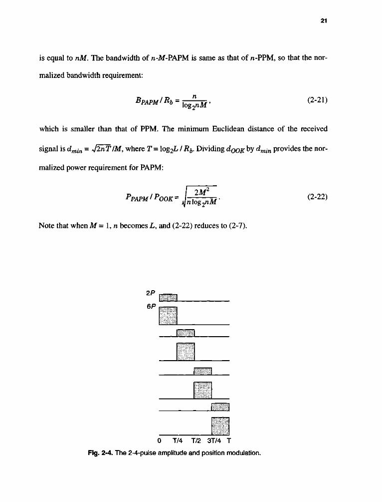
21
is equal to nM. The bandwidth of rc-M-PAPM is same as that of n-PPM, so that the nor
malized bandwidth requirement:
B PAPM' ^b /Rh = n log 2nM'
(2-21)
which is smaller than that of PPM. The minimum Euclidean distance of the received
signal is dmin - JlnT IM, where T = log2L / R^. Dividing d0QK^y dmin provides the nor
malized power requirement for PAPM:
PAPM / POOK = 2M'
\n\o%^nM
Note that when M= \,n becomes L, and (2-22) reduces to (2-7).
(2-22)
2P
6P '
2P
6P
2P
6P
"
0 T/4 T/2 3T/4 T
Fig. 2-4. The 2-4-pulse amplitude and position modulation.

22
2.1.6 Discussion
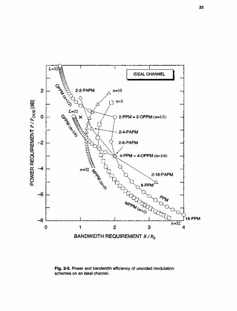
The bandwidth and power efficiency for various modulation schemes on the AWGN
channel are shown in Fig. 2-5. The benchmark modulation OOK is marked with the
symbol *x\ PPM requires less power as L increases, but its bandwidth increases as well.
MPPM with weight 2 outperforms PPM both in terms of bandwidth efficiency and power
efficiency. MPPM with weight 8 is even more bandwidth efficient, but it requires a large
number of chips n to achieve good power efficiency. OPPM with a duty cycle of a = 1/2
is extremely bandwidth efficient. Decreasing the duty cycle to a = 1/4 increases the
power efficiency at the expense of bandwidth. 2-n-PAPM is more bandwidth-efficient but
less power-efficient than L-PPM.
2.2 ACCURATE BANDWIDTH CALCULATION
There is no single universal definition of bandwidth [33]. The bandwidth of an MPPM
modulation scheme can be roughly approximated by the inverse of the shortest pulse
width that corresponds to the width of the main spectral lobe. This definition is a simple
and popular measure of signal bandwidth. Thus, the bandwidth required by OOK is
roughly the bit rate R^, and the bandwidth required by MPPM, OPPM and PPM to achieve
a bit rate R^ is the inverse of the duration of the shortest pulse, or nR^/XogyL,
(n/w)Ri)/log2L, and L7?5/log2L, respectively. For example, (2)-MPPM, (2)-OPPM and
8-PPM require 1.5, 1.4, and 2.7 times more bandwidth than OOK, respectively. More
accurately, it is common to specify the bandwidth Bx that includes x% of the signal power
[34][35]. Under the assumption that the codewords are chosen independently and with
equal probability, a general expression for the power spectral density (PSD) of any L-ary
modulation scheme is given in [35]:
23
L=321
%
-6 \-
0
4 i 1 I
IDEAL CHANNEL 1
^ S=A 2-2-PAPM rc=10
n w=3
i=32 y Q ^ V , / %, 9kx V /~
?> \gt \L
- O 2-PPM = 2-OPPM (oc=l/2)
•~f~~- 2-4-PAPM —\
P 2-8-PAPM —
I V 4 - P P M = 4-OPPM (a=l/4) —
n = 3 2 ^ ^L — n = 3 2 ^ ^L
[n C) \ s 2 - 1 6 - P A P M
4n ^^8-PPM —\
^ ^ V T > —j
16-PPM
1 2
BANDWIDTH REQUIREMENT B/Rb
n=32 3 4
Fig. 2-5. Power and bandwidth efficiency of uncoded modulation schemes on an ideal channel.
24
L-\
w-w'Lnff-^j, 1 = 0
L-\
I P,(f) 1 = 0
V*£ <f-% (2-23)
where Pt(f) is the Fourier transform of the signal corresponding to the l-th codeword.
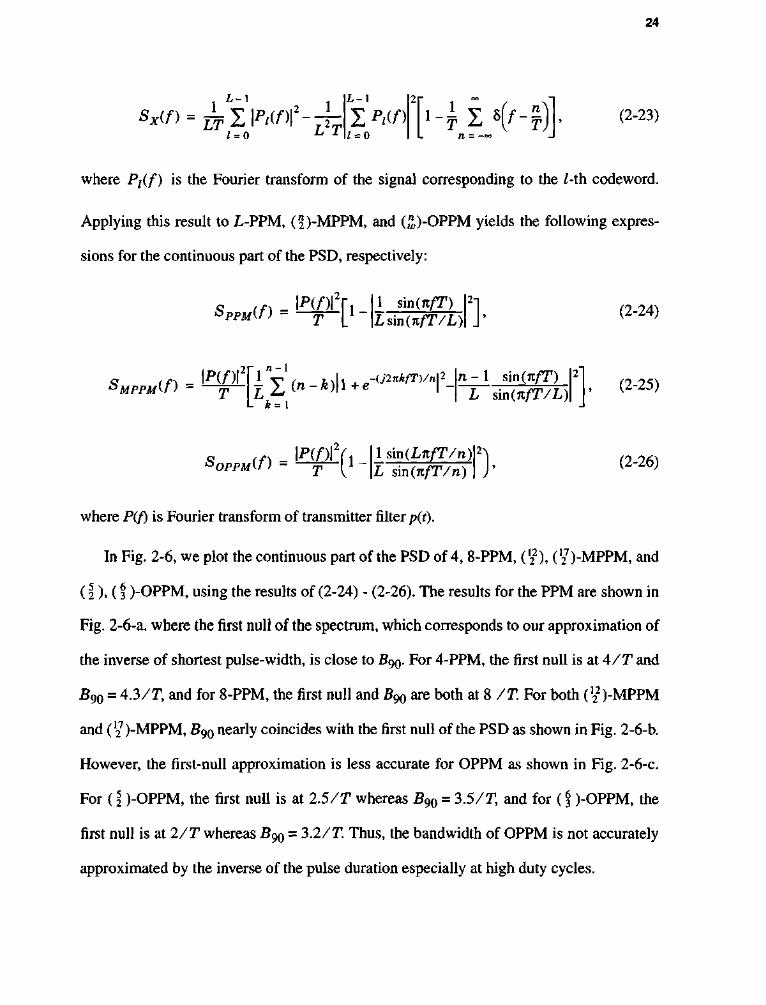
Applying this result to L-PPM, (5)-MPPM, and (£)-OPPM yields the following expres
sions for the continuous part of the PSD, respectively:
Q tf\ - \p(ft\y I1 sm(nfT) bppMin - -^-[[-\Zsm(KfT/L
2n (2-24)
2 f 1 n ~ I
SMrrulf) = W l (»-*)|l + «^"*™f -L k = 1
n - 1 sin(nfT) L sin(nfT/L)
(2-25)
o (f) _ \P(f)\ i i 'OPPM^
1 sin (LnfT/n) L s'm(nfT/n)
(2-26)
where P(/) is Fourier transform of transmitter filter p(t).
In Fig. 2-6, we plot the continuous part of the PSD of 4, 8-PPM, Ci), (127)-MPPM, and
(2 ). (f )-OPPM, using the results of (2-24) - (2-26). The results for the PPM are shown in
Fig. 2-6-a. where the first null of the spectrum, which corresponds to our approximation of
the inverse of shortest pulse-width, is close to B90. For 4-PPM, the first null is at 4 / T and
B90 = 4.3/T, and for 8-PPM, the first null and B90 are both at 8 /T. For both (122)-MPPM
and (27)-MPPM, B90 nearly coincides with the first null of the PSD as shown in Fig. 2-6-b.
However, the first-null approximation is less accurate for OPPM as shown in Fig. 2-6-c.
For (I )-OPPM, the first null is at 2.5/T whereas B90 = 3.5/T, and for (f )-OPPM, the
first null is at 2/T whereas B90 = 3.2/T. Thus, the bandwidth of OPPM is not accurately
approximated by the inverse of the pulse duration especially at high duty cycles.

25
(a)
0.6
0.5
i i 1 r
4-PPM - - 8-PPM
4-PPM BNull B 9 0
8-PPM BNull ~ B 9 0
\f\ll^ 2 3 4 5 6 Normalized frequency fT
(b)
1 2 3 4 5 6 7 8 9 1011121314151617 Normalized frequency fT
(c)
(SJOPPM B Nul l B 90
(!) OPPM BNull B 9 0
/
e '*) OPPM
- - (9 OPPM
.f^r^-,. 2 3 4 5 6 Normalized Frequency fT
8
Fig. 2-6. Power spectral density of modulation schemes (a) PPM, (b) MPPM, (c) OPPM.

26
Observe that the sidelobe of the PSD for (f )-OPPM is larger than that for ( \ )-OPPM.
To illustrate this result, consider a (3)-OPPM signal when the codeword (000111) is fol
lowed by the codeword (Oil 100), producing a chip sequence of (000111011100). The iso
lated 0 chip in position 7 requires more bandwidth than that predicted by the inverse of the
pulse width.
2.3 MPPM BOUND
In Fig. 2-5, the performance of modulation schemes using the finite length of code
word was shown. In this section, we calculate the performance of MPPM when we
increase the codeword length arbitrarily large. We use Stirling's approximation [36]:
( £ ) - > 2 a s n ^ o o , (2-27)
where h(x) - -xloggc - (1 - x)log2(l - x) is the binary entropy function shown in Fig. 2-7.
We can find a bound on the power and bandwidth efficiency of MPPM by applying (2-27)
to (2-10) and (2-11):
pMPPM/pOOK -> , > (2-28) Jh(a)/2
BMPPM/Rb -> ^7—x» (2-29)
asn->oo and a-win. We call (2-28) and (2-29) the MPPM bound, because these equa
tions represent the limit in the performance of power efficiency and bandwidth efficiency
for all (^)-MPPM. We plot the power and bandwidth efficiency of various (^)-MPPM
with the MPPM bound in Fig. 2-8. Note that MPPM with weight 2 outperforms PPM both

27
in terms of both bandwidth efficiency and power efficiency. MPPM with more weight is
even more bandwidth efficient, but it requires a large number of chips n to achieve good
power efficiency. The MPPM bound shows that as a —> 1/2, PMPPM / POOK —> 1 / 2 (—
1.5 dB) and BMPPM /Rb -> 1. As a -> 0, PMPPM /POOK ~> 0 a n d BMPPM /Rb ~> °°-
2.4 SUMMARY AND CONCLUSIONS
We have examined the performance of uncoded modulation schemes by calculating
their power efficiency and bandwidth efficiency. We have shown that MPPM and PPM are
power-efficient modulations and OOK and OPPM are bandwidth-efficient. We calculated
the accurate bandwidth of each modulation scheme by calculating the power spectrum
density, and compared this result with our first-null approximation. Our approximation is
quite accurate for most modulation schemes considered except for high-duty cycle OPPM.
To understand the behavior of MPPM, we derived a bound for the power and bandwidth
efficiency of MPPM as the codeword length n —> °o. The MPPM bound implies that using
1
0.8
_0 .6
^0 .4
0.2
0 0 0.2 0.4 0.6 0.8 1
x
Fig. 2-7. Binary entropy function.
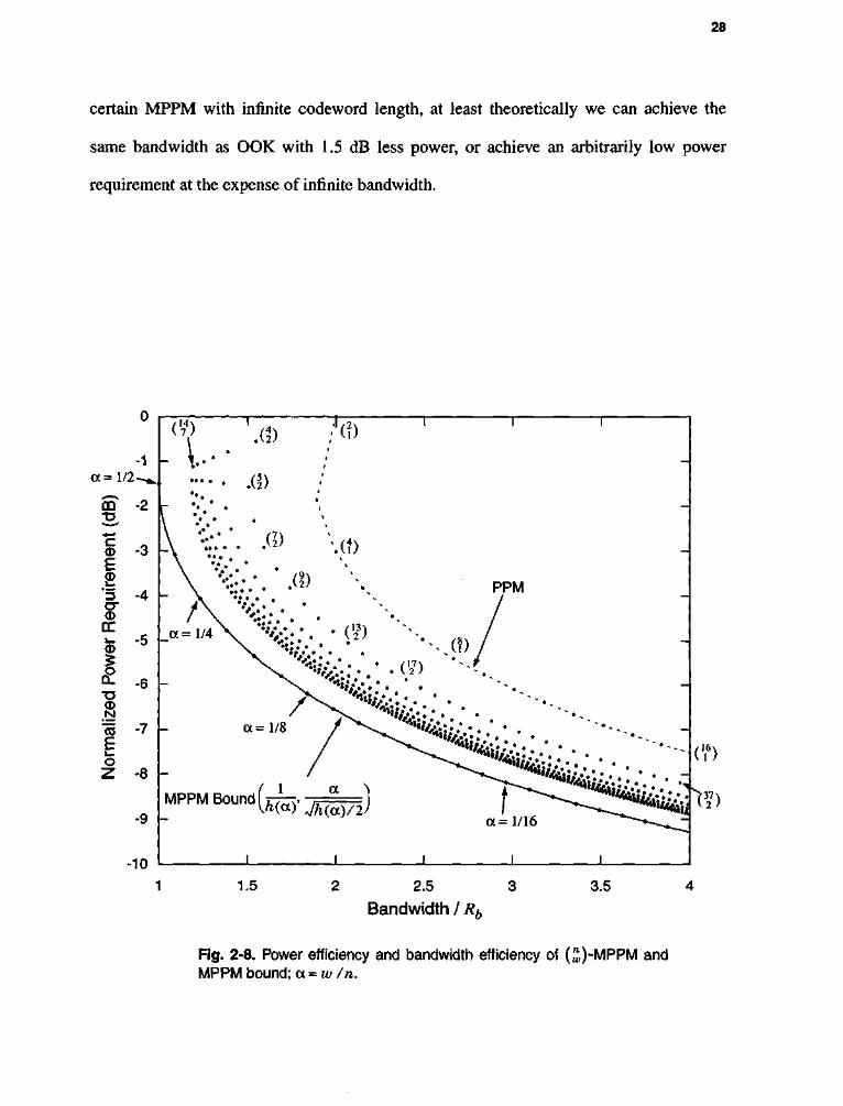
28
certain MPPM with infinite codeword length, at least theoretically we can achieve the
same bandwidth as OOK with 1.5 dB less power, or achieve an arbitrarily low power
requirement at the expense of infinite bandwidth.
-1
, Of)
I <x=l/2-
rr i _
0
£ •D <D N '« "7 E i _
o Z -8 \-
-9 \-
-10
XI)
:'(?)
PPM -t r~ \ * /
| \ % : : . ' . • : /
4 — \ •'%,;<"> •••...(,,/ \ •'*&•. • . • ( 2 }
MPPM Bound
a =1/8 / ^ ^ ***'<&:.V.. • .
>*(<*)' V^(a)/2
16>
H7)
1.5 2 2.5
Bandwidth / Rb
3.5
Fig. 2-8. Power efficiency and bandwidth efficiency of (^)-MPPM and MPPM bound; a = w /n.

CHAPTER 3
E Q U A L I Z A T I O N
In the previous chapter, we examined the performance of uncoded modulation
schemes on an ideal channel, where additive white Gaussian noise (AWGN) is the primary
source of performance degradation. In this chapter, we will include the effects of multi-
path distortion which degrade the performance further. We will consider several strategies
to mitigate the effect of this multipath distortion.
3.1 INTRODUCTION
In the diffuse link, from transmitter to receiver the signal experiences temporal disper
sion due to reflections. Usually, the received pulse duration is much larger than the symbol
duration, especially at high bit rates, and there is a cross-talk or spill-over from one
30
symbol to another. This intersymbol interference (ISI) degrades the performance of the
receiver. Equalization is the mitigation of ISI through signal processing. We consider three
equalization techniques: maximum-likelihood sequence detection (MLSD), symbol-by-
symbol equalization, and precoding.
3.1.1 Maximum-Likelihood Sequence Detection (MLSD)
Forney [37][38] showed that the optimum detector for linear PAM signals in the pres
ence of ISI consists of a whitened-matched filter (WMF) followed by a Viterbi detector.
This method is referred to as maximum-likelihood sequence detection (MLSD). The com
plexity of the MLSD grows exponentially with the channel memory. In reduced state
sequence detection (RSSD) [39] [40], the complexity of MLSD can be reduced by forming
groups of states and tracking only one surviving path per group of states in the Viterbi
algorithm. In delayed decision-feedback equalization (DDFE) [41], the complexity of
MLSD is reduced by considering a few states of the channel. The ISI due to the remainder
of the states is estimated using a feedback detection analogous to that of decision feedback
equalizer (DFE). As in the DFE, error propagation affects this algorithm. The price paid
for these methods for reduction in complexity is a performance degradation due to the
reduction of minimum distance. Barry [21] and Audeh et al [15] used MLSD to detect
PPM on a multipath channel.
3.1.2 Symbol-by-symbol Equalization
Symbol-by-symbol equalization is a suboptimal strategy for detection in the presence
of intersymbol interference. Its primary advantage over maximum-likelihood sequence
detection is a reduction in complexity. Two basic approaches to symbol-by-symbol equal-
31
ization are used: linear equalization (LE) and decision feedback equalization (DFE). The
equalization structure can be derived under the zero-forcing (ZF) criterion, which com
pletely removes the ISI, or under the minimum mean-square error (MMSE) criterion,
which weighs both ISI and noise. In ZF-LE, we choose an equalizer after a sampled
matched filter as the inverse of the folded spectrum of the channel. If the equalizer simply
inverts the channel, the receiver would enhance the noise over frequency regions where the
channel has a null. This phenomenon is called noise enhancement. The ZF-DFE recreates
the postcursor ISI from its data decision and subtracts the result from the incoming signal.
One obvious potential problem with the DFE is that any decision error will cause a cor
rupted estimate of the ISI. The result is that a single error causes a reduction in the margin
against noise for a number of future decisions. This phenomenon is called error propaga
tion. Price [42] first observed that the SNR gap to capacity at high signal-to-noise ratio is
the same for channels with ISI as it is for ideal channels, as long as ZF-DFE is used at the
receiver. In MMSE-LE, we are willing to accept more ISI after equalization to reduce the
noise enhancement. While a ZF-DFE forces the ISI to zero at the slicer input, a MMSE-
DFE minimizes the variance of the slicer error. Barry [21] and Audeh et al. [16] proposed
symbol-rate and chip-rate ZF-DFE for PPM.
Another type of symbol-by-symbol equalization is based on maximizing the a poste
riori probabilities (MAP detection) developed by Abend and Fritchman [43]. MAP detec
tion is optimum in the sense of minimizing the probability of symbol error. Simulation
results indicate that the performance of MAP detector is superior to that of DFE and com
parable to that of MLSD [22]. But unlike other equalization schemes, MAP detection
requires the knowledge of the statistics of the noise. It has found little application in prac-

32
tice due to its high complexity. Recently, Williamson et ah [44] developed a MAP detector
based on DFE (MAP-DFE). Although more complex than conventional DFE, MAP-DFE
outperforms DFE.
3.1.3 Precoding
Precoding is a technique similar to DFE that eliminates error propagation by moving
cancellation of the postcursor ISI from the receiver to the transmitter. However, this
requires knowledge of the channel response at the transmitter, a requirement that is com
patible only with channels that are stationary or slowly time-varying. Simply performing
linear equalization at the transmitter is not practical because it increases both average and
peak power of the transmitter signal. It also violates the nonnegative constraint of (1-2).
Tomlinson and Harashima [45] [46] used a modulo operation to reduce these power penal
ties (TH precoding). Recently Laroia, Tretter, and Farvadin (LTF) [47][48] introduced a
new precoding scheme referred to a LTF precoding. In LTF precoding, the postcursor ISI
is quantized to the nearest point in predetermined constellations, and only the difference
between the data signal and the quantization error is transmitted. The advantage of LTF
precoding scheme is that it supports constellation shaping on ISI channels.
In fact, with uncoded systems, precoding has not received much attention in practice.
Its performance is no better than that of ZF-DFE under the ideal decision assumption. As a
result, DFE has generally been preferred for uncoded systems over precoding because it
does not require information about the channel at the transmitter. We remark that the TH
precoding and LTF precoding are incompatible with the constraint (1-2).

33
3.1.4 Outline
The remainder of this chapter is organized as follows. In section 3.2, we develop a
vector channel model for MPPM on an ISI as a generalization of [21]. In section 3.3, we
analyze the performance of an unequalized receiver, and in section 3.4, we analyze the
performance of maximum likelihood sequence detection. In section 3.5, we consider three
symbol-by-symbol equalization strategies: zero-forcing block decision equalizer, zero-
forcing linear equalizer, and maximum a posterior detector. In section 3.6, we propose a
partial-response precoding scheme to be compatible with the infrared channel as a gener
alization of LTF precoding without considering shaping gain.
3.2 SYSTEM MODEL
Consider the system model shown in Fig. 3-1-a. Information bits with rate Rb (b/s)
enter the encoder, which maps each block of log2L bits into one of L-MPPM codewords
co ••• cL-\- We consider only binary codewords of length n and Hamming weight w. The
nP/w xk
ENC */
P/S »« Pit)
nit)
—® J hit) \-*@-^\ fit) \-^
yj
S/P S /P
Vk
Equalizer
n/T rate rate rate
log2L/T 1/T n/T (a)
rate rate rate n/T 1/T 1/T
Fig. 3-1. (a) Block diagram of MPPM system, (b) equivalent vector channel.

34
output of the encoder is a sequence of codewords {x^} with rate l/T = Rfj/\og2L. This
sequence is serialized to produce the binary chip sequence {XJ) with rate n/T, where
xk = \-xkny xkn +1» • • • »xkn + n- i\T- The binary chip sequence drives a transmitter filter with
a rectangular pulse shape p(t) of duration T/n and unity height. To satisfy the power con
straint of (1-2), the filter output is multiplied by (nP/w) before the signal is sent across
the channel.
As we explained in section 1.2, the channel model for diffuse link without fading is an
exponential decay model given by:
h(t) = We~Wtu(t), (3-1)
where W is a 3-dB bandwidth and u(t) is the unit-step function.
As shown in Fig. 3-1-a, the receiver uses a unit-energy filter fit) and samples the
output at the chip rate n/T producing yj. The receiver groups the samples yj into blocks of
length n, producing a sequence of observation vectors {yk}, where y^ - [y^, ykn + l, ... ,
ykn + n - \\T- The receiver passes each observation vector through an equalizer to form an
estimate x^ of x^. For the symbol-by-symbol equalizer, the decision device is memory-
less and has no decoding delay, however, for the maximum-likelihood sequence detector,
the decision device will have memory and a decoding delay.
The equivalent discrete-time channel between transmitted and received chips is:
oo
yj= X hixj-i + nj = sj + nr <3"2) i = - o o
where hj is the equivalent chip-rate impulse response:

35
hj = ?£(p(t)*h(t)*f(t) (3-3) t = jT/n
and where SJ is defined by (3-2).
We assume that f(t) has unit energy and is the whitened-matched filter. In this case, the
noise samples [rij] will be independent zero-mean Gaussian random variables with vari
ance iV0. As shown in Fig. 3-1-b, the equivalent vector channel between transmitted code
words xk and observation vectors yk is given by:
oo
yk= X Hjxk-j + nk=sk + rik, (3-4)
j = o
where the channel impulse response is a Toeplitz sequence H^, with [H^]y = h^ + i _j, the
signal component is sk = [skn, skn + h ..., skn + n_ j] r , the noise component is nk - [nkn,
nkn + i» • • • ' nkn + n - J7- To simplify the analysis, we will consider only \i nonzero terms in
the impulse response {H^} in (3-4).
3.3 UNEQUALIZED RECEIVER
3.3.1 Error Probability for MPPM and OPPM
By definition, the unequalized receiver uses the decision device that would be optimal
were there no ISI. In other words, it decides on the codeword ct that maximizes the corre
lation:
Kl = ClTyk for/ = 0, . . . , L - l . (3-5)

36
This unequalized decision rule is illustrated in Fig. 3-2. If we knew that xk = ct, and if we
knew all past codewords X' = {..., xk _ 2, xk _ i}, then the probability of error x k * xk
could be bounded using the union bound:
Pr[error \ xk = eit X'] < £ Pr[A{ < Aj \ xk = cb X'], j = 0,j*i
L-\
= x PrU°i - c/yk < ° I ** = <* X-],
j = 0, j * i
L-\
= £ Pr[(ct - Cj)Tnk > (ct- - Cj)
T8k | xk = ct, X'], (3-6) j = 0,j*i
where the last equality follows from (3-4). But (ct -Cj)Trik is a zero-mean Gaussian
random variable with variance dijN0, where dy = d#(Cj, c-) is the Hamming distance
between codewords ct and cj. Therefore, (3-6) reduces to:
Pr[error I xk = cit X'] < £ Q ". k
j = 0,j*i \ »JdijN0 J (3-7)
Vk
T CO
Ao
Choose Largest
T CO
Choose Largest
Ai Choose Largest
T Ai Choose Largest
T Choose Largest
AL~1
Choose Largest
T cL-\ AL~1
Choose Largest
T cL-\
Choose Largest
*A
Fig. 3-2. Decision device for the unequalized receiver.

37
Averaging overall possible codeword sequences gives:
Pr[error]< - L ^ £ £ Q (ci~c/si J^JN
(3-8) o ;
where the first summation is over all X' e C , where C is the set of L valid codewords and
|j, is the number of nonzero terms in the impulse response {H^,}.
Finally, following [26], the bit-error probability is:
l / log2L (3-9) Pr[bit error] = 1 - (1 — Pr[error])
For example, the 6 codewords of ( \ )-MPPM are:
c0 = [ 1 1 0 0 f , c1 = [10 1 0 f , c 2 = [ 1 0 0 l f ,
c3 = [0 1 1 0]T, c4 = [0 1 0 1] T, and c5 = [0 0 1 l]T.
Thus, from (3-7), the symbol error probability for MPPM given that c 0 is transmitted is:
Pr[error \ xk = c0, X'] <
Q S\ ~ S 2
+ Q ' S j - S A
oy + Q
S 0 _ S 2 + Q oy
S 0 _ S 3
07
+ Q SQ + 5 J — S2 ~ S3
0 y
(3-10)
where s;, i = 0, ..., 3, represents the chip-value of signal vector s at the output of channel.
On an ideal channel without ISI, s0 = «i = s - (P/w)Jn\og2L/Rb, and S2 = S3 = 0, so that
(3-10) simplifies to 4Q(s/j2N0) + Q(s/JW0), independent of the transmitted codeword
Xk-
As another example, (f )-OPPM has L = 4 codewords:

38
c0 = [1 1 1 0 0 0]T, c, = [0 1 1 1 0 0]T, c2 = [0 0 1 1 1 0]T, and c3 = [0 0 0 1 1 1]T.
Following the previous reasoning, we have:
Pr [error I x^ = c0, X'] <
Q (<* - < ? ^ ( 's0 s3} + Qi.
.J™o. + Q
S0 + Sl ~S3 ~S4
W s0 + SI + s2 - s 3 -S4-S5
v^; (3-11)
If there is no ISI, the symbol error probability reduces to the following, independent of the
transmitted codeword:
Pr [error] < l-[6Q(s/J2N~0) + 4Q(s/JW0) + 2Q{Jls/J2N~0)]. (3-12)
3.3.2 Extension to On-Off Keying
The model of Fig. 3-1-a can also be used for on-off keying (OOK) by setting the block
length to 7i = 1 and by setting the weight parameter to w = 1 / 2 . In this case, the bit stream,
symbol stream, and chip stream are all one in the same. If all previous bits x' = {..., Xj_ 2,
Xj_ \} were known, then the bit error probability would be [9]:
Pr[error \x'] = -Q _ 1 j V 2 - 2 > n * , - - n l • \Jh0/2 + Z'xnhj_n
J*~o 2^ V^~o (3-13)
where the prime indicates that the term n = 0 is to be omitted from the summation. By
averaging over all possible bit streams {x'}, the total bit error probability is:
1 Pr[bit error] = —V Q X
(h0/2-^'xnkj_n
Wo (3-14)
where the summation is overall all binary |X-tuples {x'\.

39
3.3.3 Simplifications when the Channel is Ideal
In this section we present simplified expressions for the symbol error probability for
the special case of an ideal channel, without ISI.
First, consider MPPM: when the channel has no ISI, the expression (3-8) simplifies to:
Pr[error] < £ NkQ k = l
\2N,j (3-15)
where Nk = Ck)Ckw) is the number of codewords with mutual distance 2k, and where
s = (P/w))Jnlog2L/Rb. This expression follows from the ISI-free results for the photon
counting channel of [49]. When w - 1, (i.e., for PPM), (3-15) simplifies further to:
Pr[error] < (L - l)Q(-i=], (3-16)
^V^V
where s = PjL\og2L/Rb and this agrees with [17].
Next, consider (^)-OPPM: when the channel has no ISI, the expression (3-8) simpli
fies to:
^ ™ ] 4 i M J ^ r h e r e M H ?-".»-.+ut-A"',,"1'<3-i7> k = i v i °y L
where again s = (P/w)Jn\og2L/Rb. This result uses the photon-counting results of [49],
Finally, consider OOK: when the channel has no ISI, then hj from (3-3) reduces to
(2P/ jR~b)Sj, and so the error probability from (3-14) simplifies to Q(P/ jN0Rb) which
agrees with the result of chapter 2.

40
3.3.4 Probability of Error Approximation for PPM
Exact evaluation of the probability of error in (3-8) is computationally infeasible as \i
becomes large. We now consider a simpler estimate for PPM based on a Gaussian approx
imation [50].
To illustrate the proposed technique, consider first OOK. Since [xj] for OOK are i.i.d.
random variables, the ISI term ^'hnXj_n is the sum of independent random variables
and can be treated roughly as a Gaussian random variable with mean 0.5^'hn and vari
ance 0.25 ]T 'hn. This Gaussian approximation leads to the following estimate of the bit
error rate for OOK [9]:
( hjl Pr[bit error] ~ Q
KjN0 +0.251'h2J (3-18)
We can use a similar technique to approximate the error probability of PPM. From (3-
4), the input to the PPM decision device can be written as the sum of signal plus ISI plus
noise:
yk = YL&ck + z + nk, (3-19)
where z is the ISI contribution:
* = X ' H * * * - , , (3-20)
where again the prime indicates that the I = 0 term should be omitted from the summation.
From (3-6), the probability that the &-th decision is erroneous given the past codewords is:
L - l
Pr[error IX'] < £ Pr[(Ci - Cj)T(nk + z) < - (cf - c/H0C; I xk = ct, X']. (3-21)
j = 0,j*i
41
Note that the mean \itj and variance a ^ of (CJ - c-fz are:
l l ^ i r C c f - c / H j l , (3-22)
P 2 . . - A Y'l l lT.TV,. . _-r..MI2_L _ V I / „ ^ A?! azl}- = j - Z'HH,'(cf - c,)llz + - 2 1/ I (Ci - c / H z l I , 0-23)
where 1 = [1, 1 ... l]T. If we approximate (CJ-CI)TZ as a Gaussian random variable with
mean |i,y and variance a2y, then (3-21) reduces to:
L~' L~' '(c,.-c/H0cI + H; Pr[error] = I £ £ Q
i = 0 j = 0, j * i ^A/||cl-cJ2iV0 + 4 ; (3-24)
As we will see the above approximation is accurate for small R^/W. Note that on the ideal
channel, the above equation reduces to (3-16).
To reduce computational complexity, we truncate the vector channel of (3-4) to four
terms, so that y^ = V , H;££ _ i + n^. This truncation will have no appreciable effect
when n is large or when R^/W is small, although it may not be accurate for small n and
large R^/W. To validate our reasoning, we calculate the ratio of the fractional energy of
h(t) contained outside the truncation length to the total energy of h(t);
oo
I h2(t)dt
e = Sc , (3-25)
jh2(t)dt 2.
n o
where Ttr represents the truncation time. We truncate up to 4n chip samples, so that Ttr =
4T. We list the fractional energy ratio for various R^IW in Table 3-1. Except OOK and 2-
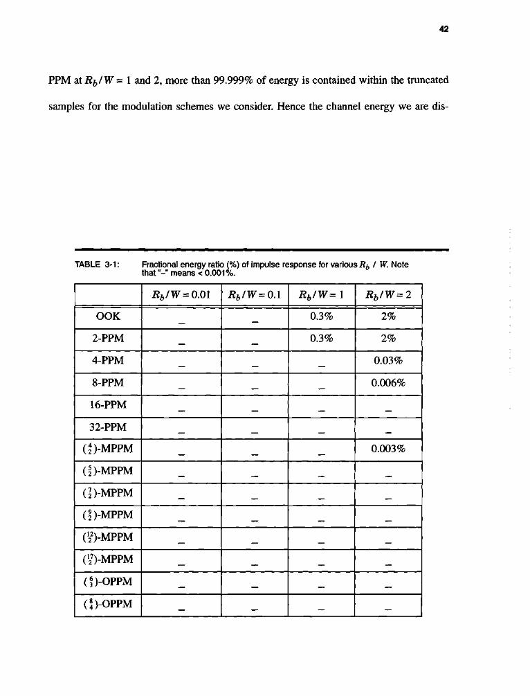
42
PPM at Rfr/W = 1 and 2, more than 99.999% of energy is contained within the truncated
samples for the modulation schemes we consider. Hence the channel energy we are dis-
TABLE 3-1: Fractional energy ratio (%) of impulse response for various R^ I W. Note that"-" means < 0.001%.
Rb/W = 0.01 Rb/W=0A Rb/W=l Rb/W=2
OOK — 0.3% 2%
2-PPM — — 0.3% 2%
4-PPM — — — 0.03%
8-PPM — — — 0.006%
16-PPM — — — —
32-PPM — — —
(J)-MPPM — — — 0.003%
(^)-MPPM — — — —
(])-MPPM — — — —
(S)-MPPM — — — —
(J22)-MPPM — — — —
(^-MPPM — — — —
(?)-OPPM — — — —
(S)-OPPM — — — —

43
carding by truncating the channel is negligible. We calculate the optical power required to
achieve a 10~6 bit-error-rate for 4-PPM over this ISI channel using the exact method (3-8)
and the Gaussian approximation method (3-24). The results are summarized in Fig. 3-3,
where the normalized power requirement is plotted versus the bit-rate-to-bandwidth ratio,
Rb/W. The power requirements are normalized by PooK= J^o^b Q-1(10 ), m e power
required by OOK in the ideal case (W = <*>) to achieve a 10 bit error rate. We can see that
when Rb/W is small, the Gaussian approximation method agrees well with the exact
method. However, when Rb/W > 0.3 the approximation is not accurate. For example the
difference between the two methods is about 3 dB when Rb/W = 0.5. We can conclude
OQ
2, +-*
c Q)
E Q) i_
"3 D" 0
DC i _ Q)
£ O
Q_ T3 CD N
75 E
12
10
8
6
4
2
0 -
-2 -
i 1—r
0.01
4-PPM
l I l I I I 1 1—l—l /l I l / / / /
/
Gaussian Approximation / / .
/ , //
// Exact Method //
I I I I I
0.1
Rbl W
Fig. 3-3. Gaussian approximation method (3-24) and the exact method (3-8) for the unequalized receiver.

44
that when ISI is small, the Gaussian assumption provides a reasonable approximation for
the error probability.
3.4 MAXIMUM-LIKELIHOOD SEQUENCE DETECTION (MLSD)
Using an argument similar to the scalar case [37], we can derive an upper bound for
the symbol error probability for the maximum-likelihood sequence detector. The MLSD
for PPM is derived in [21], and it easily generalizes to MPPM and OPPM. The MLSD
chooses the vector sequence x^ that minimizes the metric:
*»= X11^ - X H ^ _ , I I 2 . (3-26) * j
Because the input symbol x^ is chosen uniformly and independently from the set of L
valid MPPM codewords, every symbol sequence {x^} is equally likely. We define the state
of trellis at time k as:
sk-ixk-hxk-2*'-^xk-\ji* (3-27)
and there are LP states in the trellis. If the estimated codewords from the Viterbi detector
are {x^}, then the corresponding estimated state at time k is:
Sk = \.xk-\> xk-2>-~> xk-\il (3"28)
Suppose the estimated path diverges from the correct path at time k and remerges with the
correct path at time k + l + 1. Thus, S ^ = S^ and S ^ + / + j = Sk + 1 + h but S i * St for k +
\<i<k + l. We call this an error event. We define an error vector e of length I - j i+ 1 cor
responding to the error event as:
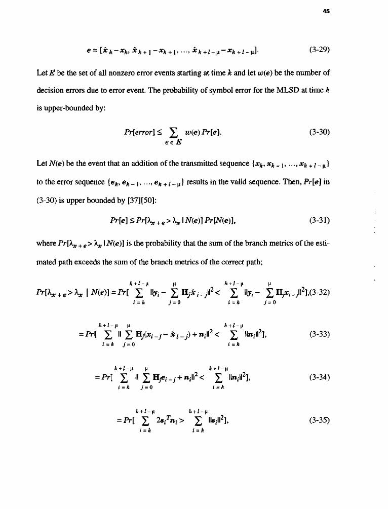
45
e = [xk-xk,xk + 1-xk + 1,...txk+i_Vi-xk + i_VLl (3-29)
Let E be the set of all nonzero error events starting at time k and let w(e) be the number of
decision errors due to error event. The probability of symbol error for the MLSD at time k
is upper-bounded by:
Pr[error]< ]£ w(e)Pr[e]. (3-30) eeE
Let N(e) be the event that an addition of the transmitted sequence {xk, xk _ j , ..., x^ +; _ H}
to the error sequence {ek, ek_ly ..., ek + ;_^J results in the valid sequence. Then, Pr[e] in
(3-30) is upper bounded by [37][50]:
Pr[e] <Pr[Xx + e>Xx\N(e)]Pr[N(e)\ (3-31)
where Pr[kx + e > Xx I iV(e)] is the probability that the sum of the branch metrics of the esti
mated path exceeds the sum of the branch metrics of the correct path;
MK + e > *» I #(«)] = *H X " II* - I %* ,• - / < X ibr* - X H ,- _/],(3-32) i = k 7 = 0 i = jfe 7 = 0
= iV[ X " X HA" -y" *i -j) + »»«2 < I "»»»2L (3-33) i = A j = 0 i = k
= Pr[ f II I H ^ ^ + ^II^ f " " A (3-34) i = k j = 0 i = k
k+l-\i k + l-\i
= Pr[ X 2 s ^ > X 'M2L (3-35) t = A j = A

46
where s, = ^ ^ H ^ _j. But 2 / 1 * H 2 s / n t is a zero-mean Gaussian random variable
with variance WQ^^'^WsiW2. Then (3-35) reduces to
Pr[Xx + e<Xx \N(e)] = Q ViU = k \ri\\
2 ^ o = Q
0 J 2 ^ o
2A
(3-36)
The Pr[N(e)] depends only on the statistical properties of the input sequence. Because
the input symbol x^ is chosen uniformly and independently, then for PPM:
Pr[N(e)] = Y[L -wH(M) (3-37)
where w^i •) is the Hamming weight. Using (3-30), (3-31), (3-36), and (3-37), we can cal
culate the upper bound of symbol error:
Pr[error] < £ w(e) ]JL eeE
-">ff(iej) Q
•lui'rim^fii.j 2 \
^tt (3-38)
Let Emin be the set of error events corresponding to dmin, the minimum distance
between received sequences:
k+l-n n
i = k j = 0
(3-39)
Then, the upper bound for probability of symbol error (3-38) can be approximated by sum
ming over Emin rather than E:
Pr[error] < ]£ w(e) \[L -«MM) Q eeE»
( d • ^
y^Woj (3-40)

47
At high SNR, (3-40) is well approximated by [51]:
Pr[error] « Q dmin
2 ^ 0 (3-41)
0 /
In Fig. 3-4-a, we plot power requirement versus Rb/W using (3-8) when equalization
is not used. We use the same truncated vector channel considered in the last section. We
see that some modulation schemes are more sensitive to ISI than others. At large band
width (Rfr/W < 0.1), the ISI penalties are small. At one extreme is OOK, with a power
requirement increasing slowly with decreasing bandwidth. At the other extreme is OPPM,
for which the power requirement grows rapidly with decreasing bandwidth. With Rb/W =
0.5, the ISI penalties, as compared to the ideal channel for OOK, ( \ )-MPPM, 4-PPM, and
(f )-OPPM, are 4.8 dB, 7.8 dB, 8.8 dB, and greater than 12 dB, respectively. It is thus
highly desirable to use signal processing at the receiver to mitigate ISI, either symbol-by-
symbol equalization or maximum-likelihood sequence detection.
In contrast to the unequalized results of Fig. 3-4-a, the results of Fig. 3-4-b are based
on the maximum-likelihood sequence detector (MLSD). Comparing Fig. 3-4-a and
Fig. 3-4-b, we see that MLSD offers significant improvement. The power requirements do
not grow as rapidly as in the unequalized case, and the normalized power requirement is
always less than 12 dB, even when Rb/W = 1. For example, when the bit rate is equal to
the bandwidth, Rb/W = 1, the ISI penalties for OOK, ( | )-MPPM, (f )-OPPM, and 4-
PPM are 4.6 dB, 8.1 dB, 9.3 dB, and 9.5 dB, respectively. We note that MLSD is far more
effective in reducing the power requirement for OOK than for other modulation schemes.

48
The bandwidth efficiency and power efficiency for PPM both using the unequalized
receiver and the MLSD are summarized in Fig. 3-5. For a small Rfj/W, the difference in
power requirement of both receivers is negligible for all L, but for large R^/W, the differ
ence is appreciable. Also, when MLSD is employed each PPM-based scheme suffers
approximately the same penalty due to ISI. For example, at Rb/W = 0.1 and R^/W = 0.5,
each PPM-based scheme requires 1-2 dB and 6-7 dB more power, respectively, to achieve
the 10"6 BER than is required at Rb/ W = 0.01.
0.01 0.1 1 0.01 0.1 1 Bit-Rate/ Bandwidth (Rb/W) Bit-Rate/Bandwidth (Rb/W)
(a) (b)
Fig. 3-4. The required power versus bit rate on an ISI channel (a) unequalized system, (b) with MLSD.
1 I I I I I I II I I I M i l l

49
We also compare the performance of PPM and MPPM when the receiver uses MLSD.
The results are summarized in Fig. 3-6. We see that MPPM is less sensitive to ISI than
PPM. For example, power penalties for 2, 4, 8, 16, and 32-PPM at Rb/W= 1 are 9.5, 9.5,
11, 13, and 15 dB respectively. Even 32-PPM starts to require more power than 16-PPM as
the Rb/W approaches 0.2. Power penalties for (J), (f), (I), (2), Ci), and (^-MPPM at
Rb/W = 1 are 8, 8, 8, 8.5, 9, and 10 dB, respectively. From Fig. 2-8, we can also expect
that MPPM is less susceptible to ISI than PPM because MPPM has better bandwidth effi
ciency than PPM for a given length of codeword n. This fact motivates us to develop trellis
coded MPPM for the multipath channel (see the section 5.4).
10
CO 8 -0 •f-f
c 6 CD E 2> 4 3 cr CD V DC j _
1 0 O
Q_ -O - 2 © N
ali
-4 E -9 -6 U
1—1—1—1—1—1—1—1—r
L = 8
E 6 /W = 0.01
J I I I I I I 2 2.5 3
Normalized Bandwidth (BI Rb)
No Equalization I
With MtSD 1
Fig. 3-5. Power efficiency versus bandwidth efficiency of PPM over ISI channel.

50
3.5 SYMBOL-BY-SYMBOL EQUALIZATION
In the previous section, we examined the performance of MLSD for MPPM. The
MLSD employs the Viterbi algorithm so that its complexity grows exponentially with the
channel memory, and so that it has a decoding delay. In this section, we will consider sev
eral symbol-by-symbol equalization techniques to mitigate the effect of ISI with reduced
complexity, as well as with small or no decoding delay.
10 DO •D S\-c <D
E 6
"g-4 <D
CL
fc2
I Q- 0 ~o E o-4
-6
-8
-10
i-
I I I I I i n I I I I I I I I
i-PPM J
I I I I I I I
i-
I I I I I I I
h / /' / J / /' / l
2 / J
I 4 / \
8
16
/ ' A
32
I i l l I I i l l I I I I MM
10
0.01 0.1 Rb/W
(a)
00 •D
8L c <D
I 6
1 4 <D
DC
% Q_
21
0 l •o
= -2 E o .4
-6L
-8^
-10
1 1
1 1 1 1 1 MM 1 1 111111
1 1
1 MPPM |
1 111111 1
1 1
1 111111
Lij> ///V \
( —
///V \
i ( i )
-LJIL- -
UiS- J
1 1 1 1 MM 1 1 i 11 I I I
0.01 0.1 Rb/W
(b)
Fig. 3-6. Normalized power efficiency versus bit-rate-to-bandwidth ratio on an multipath channel with MLSD for (a) PPM, (b) MPPM.

51
3.5.1 Zero-forcing Block Decision Feedback Equalization (ZF-BDFE)
A zero-forcing block decision feed-back equalizer (ZF-BDFE) is shown in Fig. 3-7
[21]. The received signal is passed through a forward filter of HQ . Decisions x^ are fed
through a feedback filter HQ H(Z) - 1 , and the result is subtracted from the input of a
vector slicer. Assuming correct decisions, x^ = xk, the slicer input, is then:
™k = HQ1 yk-fk= £ H o ! Hjxk -j + H o ! nk - X wo Hj*k -j = *k + H'1 nk. (3-42)
There are two decision devices that operate on wji=xk+ HQ n^. the suboptimal com-
parator that minimizes II wk - x^ II and can be implemented using a simple "choose max"
device for PPM, and the ML slicer, which minimizes II K0wk - BQxk II2.
A suboptimal decision device chooses x^ to minimize II x^ - wk II or to maximize
the correlation:
*! (** + H o l n *) (3-43)
This device is suboptimal because H0 n^ is not white.
* * . B(z)
nk r
%^>yk Ho"1 +./Os wk>
0 Decision
fk Ho" 1 ! ^ ) - ! ^
X-i
Fig. 3-7. Block diagram of ZF-BDFE [21].

52
If we knew that x^ = ct, then the probability of error x^^x^ can be bounded using the
union bound:
L-\ r - i Pr[error \xk = ct]< £ Pr[ c/{ct + H 0 nk) > ct
L(ct + H 0 nk) I xk = c J , j = 0,j*i
L-\ J l T - 1 = £ Pr[(c,- - c ^ Ho1 " * > llcjl2 - c/ci I ** = c J , (3-44)
j = 0J*i
. T T T - 1 and (cy - ci) H 0 ra^ is a zero-mean Gaussian random variable with variance iV0ll (c, -
Ci)TWQx II2. Therefore, (3-44) reduces to:
Pr[error \xk = ct]< £ Q J = o, J * i
Averaging over all possible codewords gives:
L - l L-\ (
M
II2 T HI - C J C » (c^.-Ci^H^Hy
Pr[error] < i ]T £ Q i = 0j = 0,j*i V • V^O
1,2 T C4 'CjCi (Cj-CifH.on;
(3-45)
(3-46)
The optimal (maximum likelihood) slicer chooses x^ so as to minimize II H 0u?^-
H0 ir^ II. Since the noise nk is white, the probability of error depends mainly on the
Euclidean distance d2 = II H ^ - H0Jt^ II2. We can derive an upper bound for the ML
slicer considering all the error events [16]:
L-\ L-\ /i
Pr[error]<jr^ £ Q i = 0j = 0,j*i V
HpCc^-c,-;
iM (3-47)

53
3.5.2 Zero-forcing Linear Equalization (ZF-LE)
A chip-rate zero-forcing linear equalizer (ZF-LE) uses the inverse filter g(z) = h(z)~l
where h{z) is the equivalent chip-rate impulse response as shown in Fig. 3-8. The equiva
lent channel between the transmitted chips and output of equalizer is:
rj ~ XJ + zr (3-48)
where z; is the Gaussian random variable with zero-mean and variance oz2 =
^ f h~ (eJ )dQ. Because h(z) is a causal, minimum phase filter, h(z)~l is stable, and Gz 271J-Ji
is finite. We group the chip samples into blocks of length n, and the equivalent vector
channel is:
rk=xk+zk. (3-49)
As we did in the previous section, the decision device chooses x^ to minimize Wx^ - rk\\
T or to maximize the correlation: xk (xk + zk).
If we knew that X}i = ci, then the probability of error x^x^ could be bounded using the
union bound:
Tli
Xk P/S x,- i^TPK^yHH^ 10 S / P Decision * * *
L J
Fig. 3-8. Block diagram of chip-rate linear equalizer.

54
L - l
Pr[error \xk = ct]< £ P r t cf(ci + zk) ^ ciT(ci + zk)' xk = cil j = o,j*i
L-\
= I M(cj - Cifzk > Ucfl2 - c/ci I xk = ct], (3-50) j = 0,j*i
and (CJ - ci)Tzk is a zero-mean Gaussian random variable with variance (cy - Cj)r Z (cy -
Cj), where Z = ij^z^-71]. The matrix E is a Toeplitz matrix with [L]^ = A ^ o S ^ + j - j •
Averaging over all possible codeword gives:
Pr[error]<^ £ Q L - \ L - \ f ii II2 Tn
INI ~CjCi i = oj = o,j*i \jNo(Cj-cij
rIl(Cj-ci). (3-51)
We calculate the BER of DFE with suboptimal slicer, DFE with ML decision device,
and LE with their analytical upper bounds (3-46), (3-47), and (3-51), respectively. The
results are summarized in Fig. 3-9 for 8-PPM when R^/W = 1. All simulations for DFE
include error propagation. The results of our simulation (denoted by circles) approach the
calculated upper bounds (dashed line) as the SNR increases. Therefore, we can use the
analytical upper bound to describe the performance of the DFE and LE at lower BER.
We compare the performance of the unequalized receiver, MLSD, DFE with ML deci
sion, and chip-rate LE for 16-PPM. We calculate the required power to achieve the 10"6
BER using (3-8), (3-41), (3-47), and (3-51). The results are summarized in Fig. 3-10.
When Rfj/W is small, all receivers show almost the same performance. When R^/W is
large, the receiver employing equalizers shows better performance than the unequalized

55
receiver. DFE, especially, shows better performance than the LE. DFE requires 0.3 dB
more than MLSD w h e n R b / W = \ .
3.5.3 Maximum a Posteriori Probability (MAP) Detection
We now examine the performance of a symbol-by-symbol detection method based on
maximizing a posteriori probabilities (MAP) developed by Abend and Fritchman [43].
10"1t G> +-» (0
DC 2 10-
i _
LU OQ
10
10"
-3
10 -5
I I I I L E I I I
"•Qv x »
LE,
^SN upper bound
\ J • L E ^
\\
I I I I I
6 7 8 SNR (dB)
(b)
Fig. 3-9. Bit error rate of equalization schemes and their upper bounds for 8-PPM at bit-rate-to-bandwidth ratio of 1: (a) DFE with suboptimal decision device (DFE-COM) and DFE with ML decision device, (b) LE.
10

56
We want to decide the codeword x^ given the received sequence {yk, yk + h..., y^ + p _ ]},
where the delay D is chosen to satisfy D>\i. Based on the received sequences, we decide
onax^, that maximizes a posteriori probabilities (MAP) [43]:
*k= ™ax pi*kiy*»y* + i» - . y * + i > - i ) -xk
(3-52)
By Bayes' rule:
p(xk\yk,yk + h...,yk+D-i) = p(yk>yk + v->yk+D-\\xk)p(xk)
p(yk>yk + v --^yk+D-i) (3-53)
12
10 CD
• • — •
0 8 £ 0 •3 6
CT
CC 4 0 o
Q_ •D 0 .N "co £
-2
0 . 0 1
J I I I I I
0 .1
Rhl W
Fig. 3-10. Normalized power requirement of equalization schemes for 16-PPM.

57
wherep(yk,yk + \, • • •, Vk + D -1)1S common to all, and the codewords are equally probable,
pixfi) = 11L. The MAP criterion is equivalent to choosing the x^ that maximizes:
£ = max p(yk,yk + l,...,yk+D-i\xk\ (3-54) xk
= ™ a x X I - X p(yk>yk + \->yk+D-\ixk,Xk + \-~>Xk+D-\)> O 5 5 )
where each summation is taken over the L possible codewords. We assume input code
words {xk} are equally probable and independent of the noise. Equation (3-55) can be cal
culated recursively beginning with k = 1:
*\= m^x^^--^p(y^y2-^yD^xhx2...,xD), ' Xj 3 D
= mr
a x S Z - - - Z ^ ^ 1 ^ ' -••> XD-»)••• p(yi\x2>x\)p(y\ i*i)> O56) ' X2 X-^ X'D
where p(yD I *D , ..., xD _ H) = (27iiVro)",l/2exp( - II yp - Xm = 0 H /*^ -™ l | 2 / 2N'o)» a n d w e
assume that x^ = 0 for & < 0. Unlike the other equalizer, the MAP detector must know the
variance of the noise. Observe that (3-56) involves a large number of computations,
including the summation of exponential factors, thus making it difficult to implement the
MAP detector in real applications, especially when L is large.
Williamson et al. [44] developed a MAP-like detector based on the decision feedback
equalizer structure when D = \i + 1, as shown in Fig. 3-11. The received codeword yk is
buffered to generate a sequence of D signals, {yk, y^ + 1? ..., yk + p _ 1}. An input signal in
each DFE is subtracted by the output of feedback filter. The input vectors for the decision
device are:

58
j = i
(3-57)
The MAP decision device chooses x^ based on the {w^1, wj2, ..., WJP). We can rewrite
the MAP decision rule (3-52) as [44]:
xk = ™*p(xk\yk,yk + ],...,yk+D_1) = m™p(xk\wk\wk2,...,wk
D,ek = 0), (3-58) xk xk
where ek = xk - x^, and where the second equality (3-58) assumes no error propagation.
Using the same argument used in (3-54)-(3-56),
yk
yk ^-x
z H^+.-.+H^ k
yk+i -H +
.-u H22_1+...+H^+1
yk+D-2
Y^iQ .-1
z°-] I H^"1
yk+D-i
Fig. 3-11. Block diagram of the MAP-DFE.
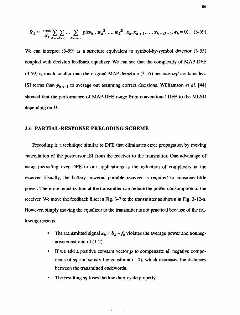
59
* * = ™X11- I p(whl.wh
2,...,u,hD\xk,xh^i,...,xk+D.i,ek = 0). (3-59)
* Xk+l*k + 2 Xk + D-1
We can interpret (3-59) as a structure equivalent to symbol-by-symbol detector (3-55)
coupled with decision feedback equalizer. We can see that the complexity of MAP-DFE
(3-59) is much smaller than the original MAP detection (3-55) because w^1 contains less
ISI terms than yk+t-i to average out assuming correct decisions. Williamson et al. [44]
showed that the performance of MAP-DFE range from conventional DFE to the MLSD
depending on D.
3.6 PARTIAL-RESPONSE PRECODING SCHEME
Precoding is a technique similar to DFE that eliminates error propagation by moving
cancellation of the postcursor ISI from the receiver to the transmitter. One advantage of
using precoding over DFE in our applications is the reduction of complexity at the
receiver. Usually, the battery powered portable receiver is required to consume little
power. Therefore, equalization at the transmitter can reduce the power consumption of the
receiver. We move the feedback filter in Fig. 3-7 to the transmitter as shown in Fig. 3-12-a.
However, simply moving the equalizer to the transmitter is not practical because of the fol
lowing reasons.
• The transmitted signal x-^-b^- f^ violates the average power and nonneg-
ative constraint of (1-2).
• If we add a positive constant vector p to compensate all negative compo
nents of Xfr and satisfy the constraint (1-2), which decreases the distances
between the transmitted codewords.
• The resulting x^ loses the low duty-cycle property.

60
nk
V© f—*-* +
fk Ho^H^-Ik
H(2) *>k
(a)
(b)
(c)
yk
Fig. 3-12. Precoding operation (a) moving DFE to the transmitter, (b) the proposed precoding scheme, (c) equivalent block diagram for (b).
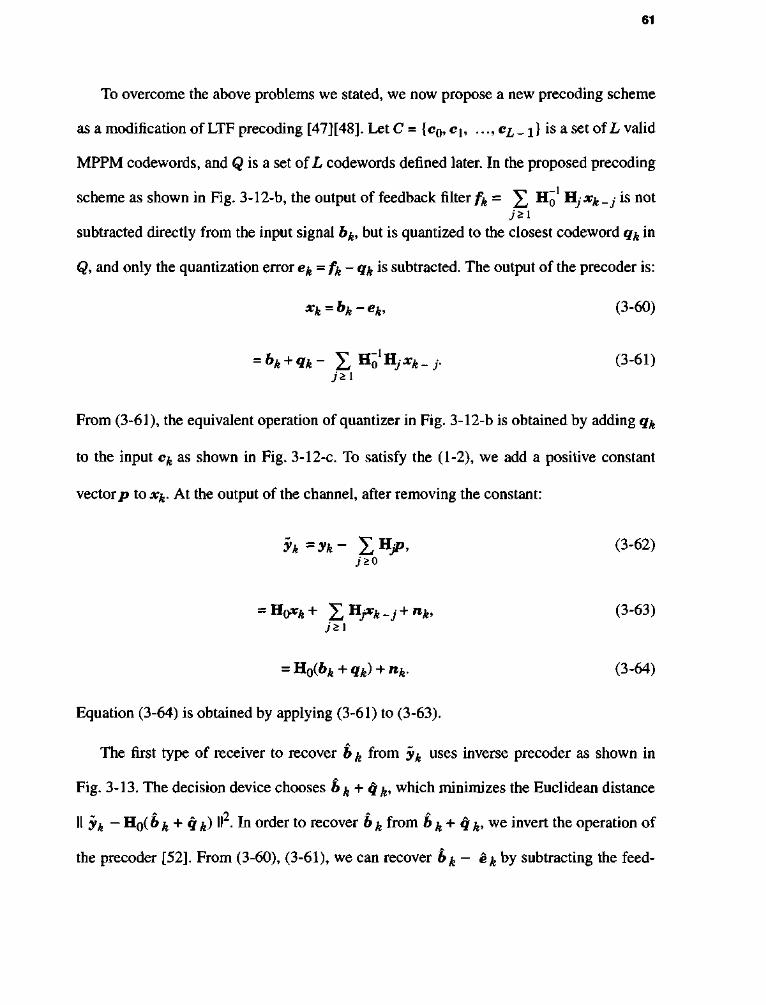
61
To overcome the above problems we stated, we now propose a new precoding scheme
as a modification of LTF precoding [47][48]. Let C = {c0,ch ..., cL_ i) is a set of L valid
MPPM codewords, and Q is a set of L codewords defined later. In the proposed precoding
scheme as shown in Fig. 3-12-b, the output of feedback filter fa = ^ HQ H/jty _j is not J'SI
subtracted directly from the input signal 6^, but is quantized to the closest codeword qk in
Q, and only the quantization error e^-fa- q^ is subtracted. The output of the precoder is:
xk = bk-ek, (3-60)
= bk + qk- X H ^ - i - (3-61) j*l
From (3-61), the equivalent operation of quantizer in Fig. 3-12-b is obtained by adding qk
to the input ck as shown in Fig. 3-12-c. To satisfy the (1-2), we add a positive constant
vector p to xk. At the output of the channel, after removing the constant:
yk=yk- ^Hjp, (3-62) j '^o
= H0*ik+ X H j * A - j + »*. (3"63) j * \
= H0(bk + qk) + nk. (3-64)
Equation (3-64) is obtained by applying (3-61) to (3-63).
A
The first type of receiver to recover b ^ from yk uses inverse precoder as shown in
Fig. 3-13. The decision device chooses b^ + q^, which minimizes the Euclidean distance A f\ A A
II yk - H0(6 k + 9 k) " • In order to recover 6 ^ from b ^ + q & we invert the operation of
the precoder [52]. From (3-60), (3-61), we can recover b^ - e^ by subtracting the feed-

62
back signal fa from b^ + q ^ We then obtain the codeword bk by adding e ^ to the b^ -
*k'
To make this precoding effective, we should design Q to ensure that (1) it minimize the
average energy of ek, in order to minimize the increment of power at the transmitter, and
(2) ensure that [b^ + q^} are distinctive, in order to decode effectively. This design of Q is
the most challenging problem of our precoding scheme. Since ek=fa- qk, qk should be
selected to be close to the fa. We assume that the equivalent discrete channel coefficients
hj are a monotonically decreasing sequence, so that the feedback signal fa =
]£ HQ HJxk_jdepends mainly on H~0 Hjx k _\ = H~0 Hx(bk_x-ek_\). We choose theL J * I
codewords, Q, according to the value of bk _ ^
Vk
l*iP
GA DEC bk + qk
-tO fk H0-'H(z)-l bk-ek
+ y-H + + bk
choose closest qk
= H 0 6 £ + H l 6 f c - 1
Fig. 3-13. Two types of receiver for precoding scheme; the upper one is an inverse precoder and lower one is for partial-response precoding.
63
qke Q={H" 1 H 1 c 0 , H"1 H l C l , ..., H ^ H ^ . x } , (3-65)
where ct is a valid MPPM codeword. Therefore, {bk + qk} are not valid MPPM code
words and the number of codewords is L2. We can expect the performance of this pre
coding to be inferior to the ideal ZF-DFE because of the reduced minimum distance
among the signal set for {bk + qk} compared to {b^}.
In the first type of receiver, we considered q^ as a valid codeword in Q. However, in
the second type of receiver we can think from a different point of view. We quantize the
feedback signal fk= ^ HQ Hya^ _j to qk = HQ H\ b^ _ t, and the quantization error is ek
7 * 1
= ]T HQ "HjXk _j - HQ HJ e^ _ j . Then the output of channel is:
yk= X H / ^ - j + n ^ (3_66) .7*0
= H0(bk + qk) + nk, (3-67)
= H0(&* + Ho1 H! 6^ _ i) + nk, (3-68)
= H06ft + H1&ft_ ! + **. (3-69)
Therefore, the precoding operation truncates the ISI channel from (X + 1 taps to 2 taps. We
call this scheme partial-response precoding . The effect of ISI caused by the truncated
channel can be mitigated using any of the equalization schemes, with reduced complexity,
that we considered in this chapter. For example, the MAP detector and its DFE implemen
tation of Fig. 3-11 are complex. However, after partial-response precoding, we can imple
ment the MAP equalizer at the receiver with reduced complexity, as shown in Fig. 3-14.
2. The term partial response is used in connection with precoding since the response to an input symbol is spread over two symbol period.
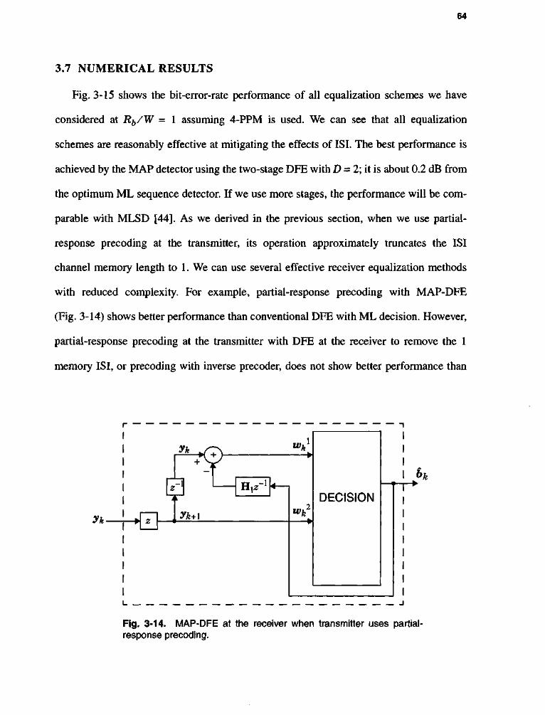
64
3.7 NUMERICAL RESULTS
Fig. 3-15 shows the bit-error-rate performance of all equalization schemes we have
considered at Rb/W = 1 assuming 4-PPM is used. We can see that all equalization
schemes are reasonably effective at mitigating the effects of ISI. The best performance is
achieved by the MAP detector using the two-stage DFE with D = 2; it is about 0.2 dB from
the optimum ML sequence detector. If we use more stages, the performance will be com
parable with MLSD [44]. As we derived in the previous section, when we use partial-
response precoding at the transmitter, its operation approximately truncates the ISI
channel memory length to 1. We can use several effective receiver equalization methods
with reduced complexity. For example, partial-response precoding with MAP-DFE
(Fig. 3-14) shows better performance than conventional DFE with ML decision. However,
partial-response precoding at the transmitter with DFE at the receiver to remove the 1
memory ISI, or precoding with inverse precoder, does not show better performance than
/v
I bk t i •
i i
Fig. 3-14. MAP-DFE at the receiver when transmitter uses partial-response precoding.
yk
Vk *6> w*J
-1 H{z - l
W z yk+\ ™k
DECISION

65
DFE. The performance of the DFE with comparator is almost the same as the LE. Note
that if the receiver does not employ equalization, the BER performance does not improve
significantly, even at high SNR.
Fig. 3-16 shows the performance of equalization schemes in terms of receiver com
plexity and performance. The x-axis represents the number of floating-point operations
(flops) per bit and the^-axis represents the required SNR to achieve 10"3 bit-error-rate. In
calculating the flops, we use the f l o p s command in MATLAB. MLSD achieves the best
performance with largest complexity. The complexity of the MAP-DFE and the precoding
with MAP-DFE is smaller than MLSD, but it is much larger than those of the other
symbol-by-symbol equalization schemes. LE requires the least complexity but its perfor
mance is poor. DFE and precoding with DFE shows good performance and small com
plexity. Especially in our applications, precoding at the transmitter and DFE at the receiver
is a good choice because of its relatively simple receiver structure.
3.8 SUMMARY AND CONCLUSIONS
We examined the performance of MPPM and its variants on ISI channels using several
equalization schemes at the receiver. Compared to conventional LE and DFE, MAP-DFE
performs well, and its performance is close to the optimum MLSD. However, its com
plexity is large and does not seem to be compatible with coding. The DFE with ML deci
sion device is effective at mitigating ISI. We developed a new precoding scheme called
partial-response precoding as a modification of LTF precoding. Accounting for both com
plexity and performance, partial-response precoding with DFE is a good choice for our
application.

I I 1 1 1 1
No equalization
| ^ b / W= 1 |
1 1 1 1
No equalization 10"1 '
1 1 1 1
No equalization
i o - 2 '
10"3
10"4
^ ^ ^ •S. «t*O^S.
-». v > o < N. \ \
v N V
N v ^ N / U ^ ^ V . ^ V v ^vk^VSn \
v. ^v^"v4rv v \ >vfl>Os.
s \ " V V N \ \ » >NJ
s * v x \ \ \ \
-A MAP-DFE
\ N i precoding with > \ inverse precoder
^ W C \ \ DFE,C0M
s ^ V X L \ N X ^ \ X \ \v V h —
\ \ « \ u \EL
10"5
MLSD N V \ pRprecod
W\\ +DFE'ML DFE(ML
sy\\/
i rv6 1 1 1
^S' \ \ Uf
PR Precoding \ \ \ + MAP-DFE \ \
1 1 \ \l
ng
10 10.5 11 11.5 12 12.5 13 13.5 14
SNR (dB)
Fig. 3-15. Performance of equalization schemes for 4-PPM at bit-rate-to-bandwidth is equal to 1.
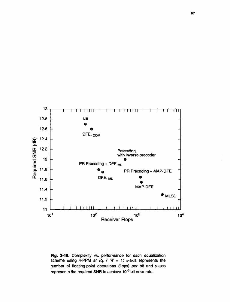
12.8
12.6
en 12.4 ID *»«*' DC 12.2 Z CO TJ 12 0 1 _
cr 11.8 0 fE
11.6
11.4
11.2
11
I I I I I I I I I I I I I I I I II I I I I I I I I
- LE -
- % -
-
D F E > COM -
—
PR Precoding +
Precoding with inverse precoder
@ — DFE,ML
— PR Precoding + MAP-DFE
- DFE, ML • ©
MAP-DFE
I I I I I I I I I I
#MLSD
I I I I I I I I I I I I I I II
101 10' Receiver Flops
10° 10-
Fig. 3-16. Complexity vs. performance for each equalization scheme using 4-PPM ar Rb I W = 1; *-axis represents the number of floating-point operations (flops) per bit and y-axis represents the required SNR to achieve 10'3 bit error rate.

68
CHAPTER 4
A C H I E V A B L E I N F O R M A T I O N R A T E A N D C U T O F F R A T E
Although bit error rate analysis in the previous chapters provides us with valuable
information about the performance of uncoded modulation schemes, it does not give us
information about the limit of performance. In this chapter, we will consider more funda
mental questions of information transfer such as:
• What is an achievable rate at SNR of 10 dB using a specific modulation
scheme?
• How much SNR is required to achieve a cutoff rate of 2 bits / channel sym
bol using 4-OPPM?.

69
4.1 INTRODUCTION
The channel capacity is the highest rate in bits per channel use at which information
can be sent with arbitrarily low probability of error [53]. The capacity of a discrete-time
memoryless channel subject to various input constraints has been studied since the advent
of information theory by Shannon. The most common input constraint is the average-
power, and the associated capacity of a Gaussian channel has already been determined by
Shannon. Channel capacity for an average-power and peak-power limited input is
achieved by discrete random variables taking on a finite number of values [54]. Capacity
for average amplitude with positive input constraint such as the wireless indoor infrared
channel (see (1-2)) has not been reported (see section 7.2.1).
Tsybakov [55] derived the channel capacity for discrete-time ISI channels with an
average input power constraint. In that case, the capacity is achieved by letting the input
sequence be correlated Gaussian random variables. Hirt [56] approximated the informa
tion rate with an independent, identically distributed (i.i.d.) input, using the Monte Carlo
method. Shamai [57] derived lower and upper bounds on the information rate for a scalar
Gaussian channel with i.i.d. input. The bounds are represented in terms of the average
mutual information of a memoryless Gaussian channel with scaled i.i.d. input symbols.
The cutoff rate is another measure of communication efficiency. While the capacity of
a channel is the rate beyond which it is impossible to communicate over the channel, the
cut-off rate is widely believed to be the rate beyond which it is very expensive to commu
nicate over the channel [58]. This parameter was initially considered in conjunction with
sequential decoding of convolutional codes. Massey [59] recognized the cutoff rate as a

70
figure of merit for modulation schemes. Biglieri [60] derived the cutoff rate of an ISI
channel using random coding bounds.
Georghiades [49] investigated channel capacity and cutoff rate for MPPM, OPPM, and
PPM over a photon counting channel without ISI.
In section 4.2, we present expressions for achievable information rate and cutoff rate
on the ideal channel when the input codewords are independent and identically distributed
with a uniform distribution. In section 4.3, we derive lower and upper bounds to the infor
mation rate over ISI channels and compare it to a Monte Carlo approximation. We also
present cutoff rate, and calculate the power to achieve log2L bits per channel symbol. In
section 4.4, we present numerical results for our channel.
4.2 MEMORYLESS CHANNEL
In this section, we will consider two fundamental limits of information transfer,
achievable information rate and cutoff rate. We assume an ideal AWGN channel with
independent and identically distributed uniform input.
4.2.1 Achievable Information Rate
In a memoryless channel, H 0 = I, Hj = 0, ... in (3-4). The information rate (bits per
channel symbol) under the i.i.d. with a uniform distribution/?^) = 1 / L over the AWGN
channel is represented by the mutual information between input and output vectors:

71
1 i.i.d. = *(**» x + n) =
iyL-u- r~ 1 -b-*il / 2 i V°i0aJ e . (4_1}
As for one-dimensional signals [58], we substitute z = (y - x{) I JWQ and vm-xml JN~0.
The above equation then becomes:
W = ^g2L-j-J4 = 0 \ _ . . . J _ — ^ e log2^Xm = 0e * J ^ - (4"2)
The above equation contains an n dimensional integral and has no simple closed form
solution. As a consequence, the Monte Carlo method is used to estimate Iiid.
4.2.2 Cutoff Rate
The cutoff rate RQ is defined when the input codewords are i.i.d. with a uniform distri
bution p(xk) = 1IL as [59]:
Ro = - iog2 f - 2 l f : d Y t ~ = o e ~ p l ~ V m f / * ) b i t s ' c h a n n e l symbol> <4-3)
where v =xI JN~0.
We can simplify for the special case of MPPM using the results for the photon
counting channel [49]:
«o, MPPM = log2£ - log2 ( X L oNke~k"2/4). (4-4)
72
p where s = — Jn\og2L/RbN0, and Nk = Ck)(n~kw) is the number of codewords with
mutual distance 2k.
Recall that PPM is a special case of MPPM with n = L and w = 1. Because PPM code
words have a unity weight and equal Hamming distance of 2, the cutoff rate can be simpli
fied to:
*o, PPM = hg2L - log2( 1 + (L - 1 )e~s / 4 ) , (4-5)
where s = PjL\og2L/RbN0.
For OPPM, we use the results for the photon counting channel [49]:
R0, OPPM = l og2L " log2f 1 + 7 X L iMke'kS / 41 > (4"6)
, , , \2(L-k) k = l,2,...,w-l P r-whereM,= ( L _ M ; ) ( L _ M ; + 1 ) A = w , and s = -Jnlog2L/RbN0
For OOK:
-sV8 * o, OO^ = 1 " log2( 1 + e~s ), where s = 2P/jRb~N~0. (4-7)
4.3 ISI CHANNEL
Following [57], we can also represent the channel using matrix notation:
Y = HX + N = S + N, (4-8)
73
where Y = \y0T, yi
T,...,y^f, X = [x0T, x^ ..., x^f, S = [s0
T, s^, ..., sN_^]T, and N
= [n0T, n-^,..., nN_iy]T are all Nn x 1 column vectors. The two equations (3-4) and (4-8)
are equivalent as N —> °o, and the rows of H are specified by circular shifts of {H;}:
H =
H0 0 0 ... 0
Hj H0 0 ... 0
0 0 HH H0
(4-9)
The achievable information rate for under the i.i.d. constraint with a uniform distribu-
t ionp(^ )= l /L i s [53] [56] :
J ^ = ^ i / ( Y ; X » = „^WY)-MY|X)), (4-10)
LN-\
=iog2z urn i x | i - j : 1 1 -MI2/2
1 = 0 •*oTN~ Nn/2
L 2n
log2
rLN-\ 2 A y e-(S (-Sm)z-| |S,-Sm | |2/2
Vm = 0
<fo.(4-ll)
Exact evaluation of this expression is not possible, so we resort to upper and lower
bounds. In the following discussion, we present lower and upper bounds for the informa
tion rate under the i.i.d. constraint. Our presentation is a straightforward generalization of
the scalar results of Shamai [57] applied to the vector channel (3-4).
4.3.1 Lower Bound of the Information Rate: J^
Following [57], we represent the entropy of the output vector by using the chain rule:
*N-\ h(Y) = I?:olHyl\yl_vyl_2,...yQ). (4-12)
Because conditioning decreases the entropy:

74
h(Y)>Yfj0lh(sl + nl\sl_l, ...,s0,nz_!, . . . ,n 0 ) ,
= Y?:olh(sl + nl\sl_l,...,s0), (4-13)
where the last equality follows because s/, nh ni_i, ..., n0 are independent. Since s/ =
£ Hl_jXj, (4-13) reduces to:
h(Y)>Yf=~oh(H0xl + nl). (4-14)
Therefore, the mutual information between the input and output vectors is:
7(X;Y) = A(Y)-A(N)^XfL'o {HH^ + n^-hi^)} , (4-15)
= 2fL"o1^Ho*/+ , i^i)- <4-16>
This equation leads to the following lower bound IL for the information rate under the
i.i.d. constraint:
^limMI/(X;Y) > hmJ^S*J(H0*Z + n,;*,) = / ( H 0 * + n;x) = IL. (4-17)
We can evaluate the above equation by replacing x with HQ# in (4-2). As we can see, the
lower bound of the information rate is equivalent to the mutual information between the
input and the output of an error-free zero-forcing block decision feedback equalizer (ZF-
BDFE) with ML-decision (see section 3.5.1) [211.

75
4.3.2 Upper Bound of the Information Rate: I(j
We now present an upper bound IJJ for the information rate Ind. °f (4-11) as an exten
sion of [57]. By using the chain rule, we can represent the mutual information between the
input and output of (4-8) as:
7(Y; X) = X f L ' o J ( Y ^ h - i ' **-2' - ' *o)>
= XfLV W*'|*'-:i>*7-2> ...,xQ)-h(xl\xl_l,xl_2, ...,x0,Y)]. (4-18)
Because {x^} are i.i.d. and conditioning decreases the entropy:
/(Y; X) <
Xz = o [h(Xi\x0, xv ..., xl_l,xl + l,xl + 2, ...,xN)~
h(xi\x0, x}, ..., Xi_ j, xl+ j, xi + 2, ..., xN, Y)] ,
= ^Ll = 0 I(Xl>X0> Xl> •••>xl-i> xl + l> xl + 2> •••> XN> * ) '
= Xz=~o I(xi'&oxi + no>'K\xi + n\> •••>mv.xi + n
v)'
= XfL"o7^ Y), (4-19)
where Y = H*z + N , and where H = [H0r, H / , . . . , H/]T, and N = [w0
T, nxT,.... w / ] T .
~ rp ~ ~ rp
Let V = H Y = Ba;j + a>, where H is a matched filter, so that B =
£m = o HmTHm , and a? is a zero-mean Gaussian vector with correlation matrix
EiwwT] =NQB. Because B is positive definite, it can be factored into B = TTT for some
matrix T [61]. We can whiten the noise by applying T to V, yielding Z = T V = TTxi
+ n, where n has the same distribution as /*/, a zero-mean Gaussian vector with correlation
76
matrix NQI. Since both the matched filter and noise whitener are information lossless, we
have l(xi, Y) = I{xt\ V) = I{xt\ Z). Therefore, (4-19) reduces to:
7(Y; X) < £fL'o /(*,; TTxt + nt). (4-20)
Finally, taking the limit as N —> °o yields our upper bound Iy of the information rate under
the i.i.d constraint:
Jim ^ / ( X ; Y ) < lim ^^-oI(<xi + ni*i) = KTTx + n;x) =IV. (4-21)
We can evaluate (4-21) by replacing x with TTx in (4-2). Note that, for the scalar case, the
matrix TT reduces to j £ |/*m|2, and the upper bound (4-21) reduces to the matched filter
bound [57].
4.3.3 Cutoff Rate
Following the discussion of [60], we can generalize the results of the scalar channel to
the vector case. Let S = (xk_l,xk_2, ...,xk_n;xk_v xk_2, ..., xk_]l), and let
S = (xk;xk) denote a state pair and a input pair respectively, and define:
1 /
0(S,S) = — exp Lt
|2 \
Ho(**-**)+ I H r a(^_m- i ,_ r a) /8JV0 m = 1 II
(4-22)
We can derive the cutoff rate of the vector ISI channel using a random coding bound
[62]:
# 0 = - l o g A ax, (4-23)

77
where Xmax is the maximum eigenvalue of a L2^ x L2^ matrix A, where Atj = ®(Sj, 5 ) , if
a state pair <S can be reached from Sj for some input pair S and A - = 0 otherwise.
For example, if L = 2 (with codewords c0 and ej) and |i = 1, then the matrix A is given
by:
A =
a b b a c d e c c e d c
a b b a_
(4-24)
where a = 1 ,
1 -PKCo-cOlVsiVo
6 = -e
1 -HHotCo-cOlVsiVo c = -e
d = le-lHo(Co-c1) + H1(c0-c1f/SN0 a n d
4 1 -fHoCco-cO + H.C )||2/8iV0
The cutoff rate can be calculated by finding the maximum eigenvalue of A and can be
approximated at high SNR as:
R0~ 1 - log 2 ( l +e"(,|Ho(Co~c,),|2 + , , H , ( C o _ C l ) | , 2 ) / 8 J V o ) (4-25)
4.4 NUMERICAL RESULTS
Because there is no simple closed form for (4-2), we use Monte Carlo methods to esti
mate the multiple integral. Fig. 4-1 shows the approximate information rate using the
Monte Carlo method and cutoff rate for 4-PPM at Rb I W = 0.01 and Rb I W = 0.5. To

78
evaluate the information rate, we use 1000 Gaussian sample vectors for each estimate
[63]. To achieve 1 bit / channel symbol, there are about 1.1 dB difference between the
information rate and the cutoff rate for the 4 PPM at a bit rate Rb I W = 0.5.
In Fig. 4-2, Iideai (4-2), II (4-17), and Iy (4-21) are shown and compared to the
approximate information rate. Our results show that IL and IJJ are 0.5 dB apart at moderate
SNR at Rb I W = 0.5. When the channel is ideal, at SNR = 3.3 dB, the information rate is
0.95 bits/channel symbol; however the information rate is only 0.18 bits/channel symbol
when Rb/W = 0.5. To achieve a information rate of 0.95 bits/channel symbol using 2-
PPM at Rb/W - 0.5, the required SNR is 9.5 dB. In contrast, we see that an uncoded 2-
PPM system with MLSD requires an additional 3.3 dB, or 12.8 dB SNR, to achieve 10"6
BER at Rb/ W = 0.5 (see Fig. 3-4-b). Thus, in this case, the coding gain for a code based
o £ >. CO
"33 c c cd
m
-10 -8 -2 0 2 SNR (dB)
8 10
Fig. 4-1. Approximate information rate, I i i d , and cutoff rate, R0, for 4-PPM as a function of SNR at Rb I W = 0.01 and Rb I W = 0.5.
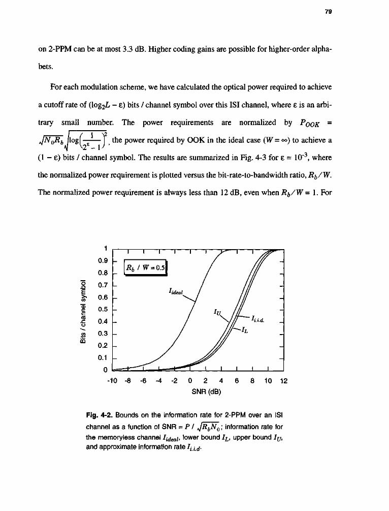
79
on 2-PPM can be at most 3.3 dB. Higher coding gains are possible for higher-order alpha
bets.
For each modulation scheme, we have calculated the optical power required to achieve
a cutoff rate of (log2L - e) bits / channel symbol over this ISI channel, where e is an arbi
trary small number. The power requirements are normalized by POOR =
jN0Rb /log f —— I the power required by OOK in the ideal case (W=oo) to achieve a
(1 - e) bits / channel symbol. The results are summarized in Fig. 4-3 for e = 10 , where
the normalized power requirement is plotted versus the bit-rate-to-bandwidth ratio, R^/W.
The normalized power requirement is always less than 12 dB, even when Rb/W = 1. For
0.9
0.8
bol
0.7 F to 0.6
nel
0.5 c CO
.c 0 4 o -* w 0.3 m
0.2
0.1
0
-10 -8 -6 -4 -2 0 2 4
SNR (dB)
8 10 12
Fig. 4-2. Bounds on the information rate for 2-PPM over an ISI
channel as a function of SNR -PI jRbN0; information rate for
the memoryless channel Itdeab lower bound IL, upper bound Iv,
and approximate information rate4;.d.

80
example, when the bit rate is equal to the bandwidth, Rb/W = 1, the ISI penalties for
OOK, (% )-OPPM, (I )-MPPM, and 4-PPM are 4.5 dB, 9 dB, 9.1 dB, and 9.2 dB, respec
tively.
4.5 SUMMARY AND CONCLUSIONS
We have examined the achievable information rate and cutoff rate of MPPM and its
variants PPM, OPPM, and OOK on an ISI channel with additive white Gaussian noise. We
have presented expressions for the information rate under the i.i.d. constraint and cutoff
rate on an ideal channel for each modulation scheme. When input codewords are i.i.d. with
uniform distribution, we have derived bounds for the information rate on an ISI that can be
_ 12 CQ 2, 10 4_^
C 0 E
8
o _ i _ 6 3 o-0
QC 4 i _
% 2 o u_ 0 TJ CI)
.N -2 CO E -4
-6
" I 1 1 I I I 1 1 1 I I I I I
0.01
l I I I I i i i I i I i I
0.1
Rbl W
Fig. 4-3. The required power to achieve a cutoff rate of (log2L -
e) bits / channel symbol (e = 10"3) normalized by POOK> versus bit
rate on an ISI channel.

81
expressed as the information rate of an ideal channel. We show that the lower bound of the
information rate is equivalent to the mutual information between the input and the output
in the block zero-forcing decision feedback equalizer (ZF-DFE) with ML decision, and
that upper bound of the information rate is equal to the vector version of matched filter
bound. We also calculate the optical power to achieve a cutoff rate of (log2L - e) bits /
channel symbol. Our results quantify the unavoidable penalties due to ISI. Among all the
modulation schemes considered here, OOK is much less sensitive to ISI than any of the
PPM-based modulation schemes, thus agreeing with the results in section 3.4.
82
CHAPTER 5
C O D E D M O D U L A T I O N
So far, we have examined the performance of uncoded modulation schemes on both
ideal and ISI channels. In this chapter, we will combine coding with modulation to
improve the error rate performance. Here we consider only convolutional code and trellis
code because we prefer to use the Viterbi algorithm at the receiver. We assume ideal chan
nels (no ISI), and the effects of ISI will be considered in chapter 6.
5.1 INTRODUCTION
The performance of modulation schemes can be improved by combining them with
coding techniques. Conventional coding operates by inserting redundant symbols into the

83
data to allow the receiver to correct errors and erasures that occur in transmission. Because
the signal bandwidth is proportional to the symbol rate, this increases the bandwidth.
Rather than treating the coding and modulation as separate processes, coded modulation
techniques combine them by matching the coding to the modulation scheme. The basis of
coded modulation is to treat coding and modulation as one entity; coded modulation is a
single process that converts the data stream directly into a suitable waveform for transmis
sion over the channel. Fig. 5-1 shows a block diagram of a coded modulation scheme. The
coded modulation performs two mapping operations. A block of (log2L - 1) information
bits, a, is mapped onto a log2L bits label vector 6 by a rate (log2L - 1) / log2L convolu-
tional encoder. The label vector b is then mapped onto a codeword x, and this mapping is
denoted by fljb) = x. In general, the mapping operation is memoryless and nonlinear.
In 1982, Ungerboeck [64] suggested trellis coded modulation (TCM) to improve the
performance without bandwidth expansion using set partitioning. He showed that a coding
gain of 6 dB relative to an uncoded system could be achieved using a trellis code with 128
states and without bandwidth expansion. Calderbank and Sloane [65] observed that the
signal constellation may be regarded as a finite set of points taken from an infinite lattice,
and the partitioning of the constellation into subsets corresponds to the partitioning of a
lattice into a sublattice and its cosets.
S / P
k
log2L - 1 w
Mapper S / P
w • • •
log2L - 1 W • • •
Mapper S / P
w
log2L - 1
w
Mapper
a b
Fig. 5-1. Block diagram of coded modulation.

84
Because the error probability of a trellis code at high SNR primarily depends on the
minimum Euclidean distance between sequences, dmin, the calculation of this parameter is
the most important task. In general, in order to evaluate the dmin of a trellis code, all pairs
of encoded sequences must be considered. Large complexity saving in calculating dmin
may be achieved if we may assume that the all-zero path may serve as the reference path.
This has already been observed by Ungerboeck and subsequently by Zehavi and Wolf
[66], Here, we consider a condition of symmetry for the signal set developed by Zehavi
and Wolf, the Z.W. condition for a rate (log2L - 1) / log2L trellis code. The Z.W. condition
requires that when the signal set is partitioned into two subsets, the distance weight pro
files of the two subsets be identical. If a trellis code satisfies this Z.W. condition, dmin can
be calculated from the all-zero path. Benedetto [67] summarized the performance evalua
tion issue in detail, analyzing different symmetry properties of trellis code design.
Optimal codes may be selected by performing an exhaustive search [64]. For a given
constraint length, we consider every possible generator polynomial, and choose the poly
nomial that gives the largest dmin. No other method is known that produces the optimal
code. However, as the code complexity increases, an exhaustive search become imprac
tical. In such cases, limited searches are necessary, even if they do not always provide the
optimal code. One simple limited search algorithm is to choose a code at random. This
natural method [68] has been reported recently. More detailed works and references on
TCM can be found in [69].
For a photon counting channel, Forestieri et al. [70] suggested several convolutional
coded PPM schemes, Georghiades [49][71] considered trellis coded OPPM and trellis

85
coded MPPM, and Pottie [72] applied the Z.W. condition to find a good trellis coded
OPPM based on the Georghiades metric.
In section 5.2, we consider convolutional coded PPM and derive an upper bound for
the dmin of convolutional coded PPM. In section 5.3, we calculate the coding gain of
trellis-coded OPPM. In section 5.4, we present a design procedure and computer search
results for new trellis codes based on MPPM, and derive an approximate upper bound for
the dmin of trellis-coded MPPM.
5.2 CONVOLUTIONAL CODED PPM
In this section, we will combine convolutional encoder with PPM. Uncoded PPM is a
power-efficient modulation, and its error rate performance will be improved further using
coding, at the cost of increased bandwidth.
5.2.1 Rate 1 / log2L Convolutional Coded L-PPM
One method for combining a convolutional code and PPM is a rate l/log2L convolu
tional code followed by a L-PPM encoder [70]. For every information bit coming in, a
single pulse is transmitted. Thus, the symbol rate and bit rate are identical, and the
required bandwidth is roughly LIT, so the normalized bandwidth requirement is:
BCC,i/\og2L/Rb=L- (5-1)
The bandwidth increases linearly with L.
A simple convolutional coded 4-PPM and one stage of its trellis diagram are shown in
Fig. 5-2. Associated with each transition on the trellis diagram is a 4-PPM codeword.

86
Consider a rate l/log2L convolutional code with constraint length v (i.e., with v
memory elements). We will use a similar argument as in [73]. An information sequence of
length K bits results in a sequence of K+v PPM symbols. Because of the encoder
memory, two information sequences that differ by only a single bit will result in two trellis
paths that disagree in exactly v + 1 consecutive transitions. For example, the trellis in
Fig. 5-3 shows the two paths corresponding to the all-zero sequence and a single one bit.
Two paths can differ in more than v + 1 consecutive transitions, but never less. As illus
trated in Fig. 5-3, the Hamming distance between any two branches is either zero or 2.
Therefore, an upper bound on the squared minimum Euclidean distance for convolutional
coded PPM is:
d2min<2(v+l). (5-2)
If we design the convolutional encoder so that the distance in each of the v + 1 transitions
is always 2, then the Hamming distance due to a one-bit error is 2(v + 1). In particular, the
squared minimum Euclidean distance for the convolutional encoded PPM system of
Fig. 5-2 is dmin = 6, so it satisfying with equality.
Fig. 5-2. A convolutional coded 4-PPM and its trellis.
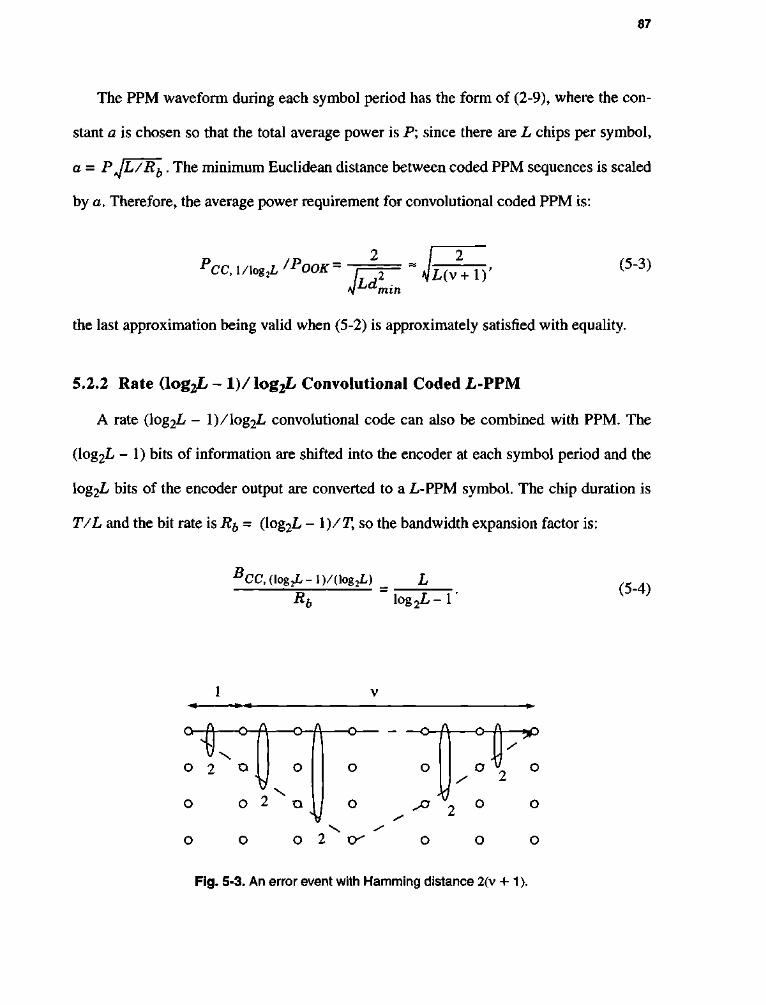
87
The PPM waveform during each symbol period has the form of (2-9), where the con
stant a is chosen so that the total average power is P; since there are L chips per symbol,
a = PjL/Rb. The minimum Euclidean distance between coded PPM sequences is scaled
by a. Therefore, the average power requirement for convolutional coded PPM is:
PCC,\/\og2L/POOK =
fi4ni L(v+1) ' (5-3)
in
the last approximation being valid when (5-2) is approximately satisfied with equality.
5.2.2 Rate (log2L - l ) / l o g 2 L Convolutional Coded L-PPM
A rate (log2L - l)/\og2L convolutional code can also be combined with PPM. The
(log2L - 1) bits of information are shifted into the encoder at each symbol period and the
log2L bits of the encoder output are converted to a L-PPM symbol. The chip duration is
T/L and the bit rate is R^ = (log2L - 1)/T, so the bandwidth expansion factor is:
B CC, (log2L-l)/(log2L)
Ru iog2L- r (5-4)
o- <H\ o 2 o
\)
•o-fl
o
o
0 \ O 2 o
^
O
o
O 2 o^
/
/
-w x° 2 -
o o
•^sP
o
o
o
Fig. 5-3. An error event with Hamming distance 2(v + 1).

88
Following the same argument used in section 5.2.1, we can derive the upper bound for
the minimum distance. The minimum distance of convolutional coded PPM is the smallest
among the distances of pairs of sequences arising from an error event. Each trellis path of
length I involves I PPM codewords. We define the trellis path vector X = [x0T, xx
T, ..., xt _
iT]T of dimension IL, where xi is an L-PPM codeword. If Sa and S^ are two trellis states yrl \ i
that are connected by a path of length Z, then the number of trellis paths is M(l) = 2 if
I > v [74] where K = (\og2L - 1). The minimum distance is less than an average distance:
M - 1 M - 1
dmin = g {^-^}<d2avg = — 1 — X I IKMCTI2 (5-5)
V Ji = 0 j = 0
M-lM-l
= M(M_X) I I [iiyii2 + i i» ' i i2-2(y,»)]. (5-6) ( i = 0 j = 0
J*l
When two trellis paths, X1 and X7, are orthogonal to each other, (X1 , X7) = 0, (5-6) is
upper-bounded:
? M - 1
*2min*]zl IIX¥ = 2Z = 2 1 + | Y | , (5-7) i = 0 L J
where the first equality follows from fact the that every trellis X1 contains I weights, K is
equal to (log2L - 1), and L«J takes the integer part of its argument. We can see that for K =
1 (L = 4), the upper bound (5-7) reduces to (5-2).
In comparison, the simplex bound is [74]:
4 <min^lll(1+h\). (5-8) mln i>l 2Kt_j l , |_KJJ >
89
Fig. 5-4 shows the calculated minimum distance of convolutional coded PPM with its
upper bounds (5-2) and (5-7), and simplex bound (5-8). We can see that our upper bound
is tighter than the simplex bound. To calculate the dmin of rate 1 / 3 convolutional coded 8-
PPM and rate 1/4 convolutional coded 16-PPM, we use the generator polynomial listed
in Table 11.1 of [75]. For rate 1/3 convolutional coded 8-PPM and rate 1/4 convolutional
coded 16-PPM, the calculated dmin achieves the upper bound up to v = 10 and v = 12
respectively. For rate 2 / 3 convolutional coded 8-PPM and rate 3 / 4 convolutional coded
16-PPM, we use the search results listed in [14]. In these cases, the search results ofdmin
achieve the upper bound for every v we consider. As in (2-9), the constant a is chosen so
that the total average power is P; unlike (2-9), however, there are L chips per symbol, not
log2L, and the symbol period is T = (log2L - l)/i?&, not 1/ify,, so that
a = PAjL(\og2L- l)/Rb. Therefore, dooK^^min giy e s m e power requirement as:
PCC,(\og2L-\)/(\og2L)/POOK- / 2 ~ / , ,y (5"9) 4LKd2
min J L K ^ 1 + I Y | J
the last approximation being valid when dmin ~ 2[ 1 + Y. J, where K = (log2L - 1).
From (5-4) and (5-9), we see that, with respect to bandwidth efficiency and power effi
ciency, the rate (log2L - l)/log2L encoders are better than the rate l/log2L encoders.
We also compare the performance of convolutional coded 16-PPM with the cutoff rate
bound. The cutoff rate bound for a coded system is defined as the SNR at which the cutoff
rate, RQ, is equal to the same number of information bits per symbol period [68]. We cal-

90
culate the RQ bound using the equation (4-5). For convolutional coded 16-PPM, 3 informa
tion bits are transmitted per symbol period. The result is shown in Fig. 5-5. For
2 3 4 5 6 7 8 9 10111213
Constraint Lengths (a)
14
13
12
11
<» c 10 S 9
8
7
2 / 3 C.C 8-PPM]
simplex bound /
6 6 10
Constraint Lengths (c)
search result
l__l L_J I I I I L
2 3 4 5 6 7 8 9 1011 1213
Constraint Lengths (b)
<N
^
12
11
10
9
8
7
6
5
4
3/4C.C16-PPMI /
simplex bound
search (5-7) result \ /
\ V / ^ — O —
5 6 7 8 9
Constraint Lengths
(d)
Fig. 5-4. The calculated minimum distance (denoted by circles) of convolutional coded PPM with its upper bounds (5-2) and (5-7) (denoted by solid line), and simplex bound (5-8) (denoted by clashed line).

91
convolutional coded 16-PPM with v = 6, the SNR needed to achieve 10"6 BER is 0.6 dB
more than that of the cutoff rate bound. However, uncoded 8-PPM, which has the same
number of information bits per symbol period as coded 16-PPM, requires 3.7 dB more
than the cutoff rate bound.
5.3 TRELLIS CODED OPPM
If we use a convolutional code to reduce the probability of error, there is an inevitable
increase in bandwidth, as derived in the section 5.2. It is well known that trellis-coded
-1 10
1 0 * -
B 10"3
CO DC
1 10"4
111 bo
10"° -
10"b -
10 -7
-4
-
I I I I ; i i i i
] R0 bound • s- (3 bits / channel symbol)
-Cutoff rate bound |
; i i i i
] R0 bound • s- (3 bits / channel symbol)
-
; i i i i
] R0 bound • s- (3 bits / channel symbol)
1 ^ \ uncoded 8-PPM
-convolutional coded ^^ 16-PPMwithv = 6. \
\ ' \
-j \ 0.6 dB \
-
I I I I
'. A. 3-1 dB \ -
I I I I ! i \ i i i \
•1 0 1
SNR (dB)
Fig. 5-5. Convolutional coded 16-PPM with cutoff rate bound.

92
modulation (TCM) is a technique that improves performance without increasing the band
width. Because PPM has the same Hamming distance between any two codewords, no
gains can be made through set partitioning. OPPM is an attractive alternative since it has a
low duty cycle and equal energy signals [49][71]. But doubling the number of (L / 2)-
OPPM symbols without increasing bandwidth, as Ungerboeck suggested [64], requires
that the overall duty cycle a = w/n remain fixed, and so the number of slots in each baud
interval must increase from nu = (L/2 - 1)/(1 - a) to nc = (L - 1)/(1 - a), which, in
turn, decreases the minimum distance. Ideally, the coding gain achieved through set parti
tioning will be large enough to compensate for the decreased minimum distance. Trellis
coded L-OPPM has a bit rate of Rb = log2(L/2) / T and a bandwidth expansion factor of:
BTc, L-oppM/Rb = i^TTTy ( 5 " 1 0 )
which is the same as L/2-OPPM. However, now the required power is:
PTC, L-OPPM/POOK= l~~2 • (5-11) idz
min,c ( l - a ) l o g 2 ( L / 2 )
In contrast, the requirement for uncoded (L / 2)-OPPM is:
P0PPM/P00K= H 4 ( L / 2 " ' ) C t 2 . (5-12) CL min, u • ( l -oc) log 2(L/2)
where dmin^ c and dmin^ u = Jl are the minimum Euclidean distance for the coded and
uncoded systems respectively. The asymptotic coding gain is [28]:
( W . / 9 _ 1 \ rf2~:- ^ /<*-.- . Asymptotic Coding Gain = 101og10 ( L/2— I) d min,c\ i n , „ ( min,c\ / c n\
-rrr) • —2-\" m°H^-)- (5"13)
93
where the first term represents loss due to expansion in size of constellations and the
second term is gain due to coding. To get improved performance using TCM, the min
imum Euclidean distance must be greater than about 2.
The signal sets for 8-OPPM (L = 8, nc = 14, wc = 7) and its set partitioning are shown
in Fig. 5-6. If we use a 4-state TCM, the minimum Euclidean distance is Js, which is the
distance for a parallel transition resulting from the set partitioning. From (5-13), therefore,
the asymptotic coding gain relative to uncoded 4-OPPM (with nu = 6,wu = 3) is 1.2 dB.
We have seen that trellis coded OPPM improves the power efficiency without band
width expansion. But, the improvement is not appreciable due to its relatively small
number of codewords given the length of codeword.
5.4 TRELLIS CODED MPPM
In the previous sections, we combined coding with PPM or OPPM. Convolutional
coded PPM improves the power efficiency with a large sacrifice in bandwidth efficiency.
Trellis coded OPPM achieves better power efficiency than the uncoded OPPM without
bandwidth expansion. But, as we indicated before, this scheme does not provide us with
good power efficiency compared to the other coded modulation schemes.
In this section, we will develop new trellis codes based on MPPM. Since MPPM is
both power-efficient and bandwidth-efficient, trellis-coded MPPM improve the power-effi
ciency without significantly increasing the bandwidth.

94
5.4.1 Design of Trellis Coded MPPM
In general, l o g 2 0 is not an integer, therefore MPPM can not be used straightfor
wardly at the output of convolutional encoder. The design rule is to choose n and w so that
(w) is close to the power of 2 in order to minimize the loss of throughput. For w > 2, n
must be too large to get good power efficiency. Therefore, we choose w = 2 as a good
starting point. The MPPM codewords with w = 2, can be mapped into a plane. Fig. 5-7
shows (")-MPPM codewords for n = 5, 7, 9, 13, and 17. This idea is similar to [76], where
an optical pulse is mapped into a plane by assigning the starting time of a pulse to the x-
c0 c, c2 c3 c4 c5 c6 c7
(C0, Ch C2, C3, C4, C5, CQ, C 7 )
/ \
( C 0 , C 2 , C 4 , CQ) (Ch C3, C5, C 7 )
/ \ / \ (c0,c4) (c2,c6) (chc5) (c3,c7)
d2
Lb T
Fig. 5-6. The 8-OPPM signal set and its set partitioning [71].

95
axis and the ending time to thejy-axis. In our case, the *-axis represents the position of first
pulse, and the j'-axis represents the position of second pulse. For example, codeword [1 1
0 0 0]Tis mapped into (1, 2), [ 0 0 1 0 lj^is mapped into (3, 5), and so on. Note that Ham-
1
4 1
o— - 9 — T ( 3 ) -v —•—
T (5 ) •XT — •
(7)T
4-T(12)
O • (0)
• 0)
® (2)
-j
4-j(ii)
(15) O O -J
4-T(io)
® (14)
O -j
4-T(9)
® (13)
-I
4-T(8)
1 _J _J I
" 1
(b)
9 o 8
(22) O
(9) T(10) T(11) T(12) T(13) T(14)
® © @ @ @ • (4) (5) (6) (7) (8)
|(21) (27) (1) (2) (3)
6 f - © ® O © T(20) (26) (30) (0)
5 4- @ ® ® T(19) (25) (29) (31)
4 4- ® ® T(18) (24) (28)
3 4- © T(17) (23)
2 4-1(16) J L J I I L
(C)
(15)
13 Q — • -TsBrfHilfeTrtc 12 #* o
[(42) 11 4- @
T(41)(51)
10 4" @ 1(40) (50)
9 4- © T(39) (49)
8 4 " ® 1(38) (48)
T(37)(47)
6 4" © T(36) (46)
5 4" ® T(35) (45)
4 4- @ T(34) (44)
3 4 - ® [(33) (43)
2 4-1(32)
'(21) T(22) T(23) T(24) Y(25) Y (26) Y(27) Y(28) Y(29) Y(30)
© @ @ © @ ® @ -
(fi) (T5) (T6) (T7) (ft) (Tl) (20) (12) (13)
0 8 ® O (58)
® ® (57) (63)
® ® (56) (62)
® ® (55) (61)
(54) (60)
® ® (53) (59)
® (52)
(6) (7) (8)
(0)
O
O
O
O
(2)
O
O
(9) (10) (11)
© © (3) (4)
O
J I \ I I I L
5 6
(d)
(31)
10 11 12 1 2 3 4 5 6 7 8 9 10 11 12 13 14 15 16
(e)
Fig. 5-7. Constellations for (2)-MPPM; the shaded circles represent the chosen L codewords and unshaded circles represent the unused codewords. The *-axis represents the position of first pulse and the y-axis represents the position of second pulse, (a) L = 8 and n = 5, (b) L = 16 and n = 7, (c) L = 32 and n = 9, (d) L = 64 and n = 13, (e) L = 128 and n = 17.

96
ming distance between the two codewords having the same ^-component or ^-component
is two, and Hamming distance between the two codewords having different ^-component
and -component is four.
The Zehavi and Wolf condition requires that when the signal set is partitioned into two
subsets, S^ ' and S^\ the distance weight profiles of the two subsets be identical. The dis
tance weight profiles of a subset with respect to log2L-tuple binary error vector e is
defined as [66][67]:
F(SF>, e, Z) = X ^ H ( / ( 6 ) ' A 6 e e > ) fori = 1, 2, (5-14) d
where Nd is the number of codewords having Hamming distance d between the codeword
fib) and codeword fib © e), and the summation is taken over all the possible d. If trellis
code satisfies this Z.W. condition, then dmin can be calculated from the all-zero path. In
Fig. 5-7, the shaded circles represent the L selected codewords, and the number below
each constellation point represents the label of the codeword. Fig. 5-8 shows set parti
tioning of 8-MPPM. The 8-MPPM signal set is partitioned into two subsets, S (1) = {0, 2,
4, 6}, and S^ = {1, 3, 5, 7}. The distance weight profile of these subsets are listed in
Table 5-1, and they are identical. Therefore the resulting 8-MPPM satisfies the Z.W. con
dition. By calculating the distance weight profile (5-14), we can prove that the other
MPPM signal sets, shown in Fig. 5-7 also satisfy the Z.W. condition.
We choose (27)-MPPM as an uncoded modulation scheme upon which to design a
trellis code. From d) = 136 MPPM codewords, we choose 128 codewords to combine
with the rate 6/7 convolutional encoder, as shown in Fig. 5-7-e. For trellis coded 128-

97
MPPM, a random search is executed over systematic feedback convolutional encoder as
shown in Fig. 5-9. The rate 6/7 convolutional encoder operates on 6 bits, ak =
[ak,ak,ak,ak,ak,ak] , and produces 7 encoded bits, a labeling vector b^ =
[bk, bk, bk, bk, bk, bk, bk] . The coded bits are mapped into one of the 128-MPPM code
words according to the mapping rule /(•). We choose a systematic feedback configuration,
because it has a smaller number of coefficients to search than that of feedforward configu
ration, also it is free from catastrophic condition [64]. For 128-MPPM with constraint
length v, the number of coefficients to search is 27^v ~ , making it is almost impossible to
perform an exhaustive search for a large constraint length.
d4 mm
1 2 3 4 1 2 3 4 1 2 3 4 1 2 3 4
Fig. 5-8. Set partitioning of 8-MPPM.

98
TABLE 5-1: The distance weight profile of trellis coded 8-MPPM.
Error vector e
S r i>={0,2,4,6} S ( 2 )= {1,3,5,7}
000 4 4
001 2Z2 + 2Z4 2Z2 + 2Z4
010 4Z2 4Z2
011 4Z2 4Z2
100 4Z4 4Z4
101 4Z2 4Z2
110 2Z2 + 2Z4 2Z2 + 2Z4
111 2Z2 + 2Z4 2Z2 + 2Z4
The random search results are shown in Table 5-2. We compare this trellis coded
MPPM with the uncoded modulation that has same bandwidth efficiency. Trellis coded L-
MPPM has a bit rate of Rb = log2(L / 2) / T, and bandwidth and power efficiencies are:
TC, L-MPPM
Ru n
l og 2 (L /2 ) ' (5-15)
TC, L-MPPM 2w
*00K Jnd2min,clog2<iL/2)
(5-16)
where dmin c is the minimum Euclidean distance of coded sequences. Define the integer
L so that L -PPM has the same bandwidth efficiency as trellis coded L-MPPM. The

99
asymptotic coding gain over L -PPM, with the same bandwidth efficiency and minimum
Euclidean distance dmin u = Jl, is:
Asymptotic Coding Gain = lOlogjo ' <nlog2(L/2) f
w Llog2^ ,(dB) (5-17)
J
where the first term represents loss due to expansion in size of constellations and the
second term is gain due to coding. We find L = 9 for PPM since trellis coded 128-MPPM
and 9-PPM have approximately the same bandwidth efficiency, BI Ri~ 2.8 in both cases.
Using the constraint lengths 4, 7, and 12, we achieve an asymptotic coding gain relative to
uncoded 9-PPM of 1.4, 2.3, and 2.9, respectively.
Fig. 5-9. Systematic feedback encoder for trellis coded 128-MPPM with constraint length v and parity check coefficients hm
n, m = 1, 2, . . . ,v-1 andra = 0, 1, ...,6.

100
TABLE 5-2: Parity check coefficients for trellis coded 128-MPPM in octal form. Coding gains are calculated as compared to the uncoded 9-PPM which has the same bandwidth efficiency as coded 128-MPPM. Random search is used to find the coefficients of trellis codes. To validate the search result, we compare this with the davg and the simplex bound. Note that the performance of trellis codes for v = 5 and 6 are no better than v = 4, and trellis codes for v = 8, 9, 10, and 11 are no better than V = 7.
V Parity Check Coefficients d 2
umin 'req
(dB)
Cod
ing
Gain
[dB]
aavg
(Sim
plex)
V
h° hl h2 h3 h4 h5 h6
d 2
umin 'req
(dB)
Cod
ing
Gain
[dB]
aavg
(Sim
plex)
4 23 10 06 14 16 00 04 4 -7.0 1.4 4
(4)
5 65 14 34 22 12 20 16 4 -7.0 1.4 4
(4)
6 103 054 072 016 014 024 066 4 -7.0 1.4 7
(8)
7 357 144 014 024 040 140 102 6 -7.9 2.3 7
(8)
8 443 102 040 064 276 022 164 6 -7.9 2.3 7
(8)
9 1057 0516 0324 0546 0720 0604 0206 6 -7.9 2.3 7
(8)
10 3341 1406 1330 0176 1266 1746 1156 6 -7.9 2.3 7
(8)
11 7433 0736 1162 1316 2032 2272 3302 6 -7.9 2.3 7
(8)
12 10017 02102 05242 03314 01374 07550 01044 8 -8.5 2.9 11
(12)
101
5.4.2 An Approximation for the dmin of Trellis Coded MPPM
In this section, we derive an approximation for the minimum distance of trellis coded
MPPM for a given constraint length. The minimum distance of a trellis code is the
smallest among the distances of pairs of sequences arising from an error event. Each trellis
path associated with the error event of length I involves I MPPM codewords. We define the
trellis path vector, X = [x0T, xx
T, ...,xi_ iT]T of dimension In where xt is the (^)-MPPM
codeword corresponding to the i-th branch in the path. Observe that the trellis vector X is a
valid ([J)-MPPM codeword with length N = In, and weight Q. = Iw. As we indicated in
section 2.1.3, any valid MPPM codeword has the same set of distance with respect to the
other codewords, and the number of codewords for (Jj)-MPPM with mutual Hamming dis
tance 2m is Nm = (")(N^Q). We can calculate the average distance for (JJ)-MPPM as:
L - i L - i 2
davg = L(L-l)^ £ l x i - X i • (5"18>
^ ^V-Xf , (5-19)
Q
I m = 1
i B
= ZZ-11.2mNm- (5-20)
(5-21)
102
where L = (£) is the number of extended MPPM codeword. Since not all valid (JJ)-MPPM
-1 codewords are included in the set of {X}, the davg in (5-18) is only an approximation for
d2
rnin '
We also can apply this approximation method to trellis-coded PPM by treating the
trellis-coded PPM sequences of length I as extended MPPM codewords with length N = IL
and weight Q = Z, and then apply (5-21).
The approximation based on average distance are listed in Table 5-2. For comparison,
we calculated the simplex bound:
. ~ K * + 1
,2 . mm 2 (. min t>\2Kt_\ v
where K = (log2L - 1), and |_*J takes the integer part of its argument. We can see that
approximation method is tighter than the simplex bound.
5.5 PERFORMANCE OF CODED MODULATION SCHEMES
We calculate power efficiency and bandwidth efficiency of coded modulation schemes
using (5-1), (5-3), (5-4), and (5-9) for convolutional coded PPM; (5-10), (5-11) for trellis
coded OPPM; and (5-15), (5-16) for trellis coded MPPM. We assume each coded modula-
tion has dmin = 4, 6, ..., 16. We ignore the complexity problem to achieve this, since this
assumption may require a large constraint length for some coded modulation schemes.
The result along with MPPM bound is shown in Fig. 5-10. The most power-efficient
scheme is convolutional coded 16-PPM with bandwidth efficiency of B I R^ - 5.3. The
most bandwidth-efficient scheme is trellis coded 8-OPPM, but it has poor power effi-
(5-22)

103
ciency. The next power-efficient scheme with moderate bandwidth efficiency of B I Rb =
2.83 is trellis coded 128-MPPM. Note that this scheme requires approximately a half
(2.83/5.3 = 0.53) of the bandwidth required by the convolutional coded 16-PPM. There-
CO -2 -o -2
H - J
c 0
-3 E
ire
-4 13 o-0 -5
CO
E i _
o
Trellis coded
8-OPPM
DC
I •D 0 N ^ -8 U
-6 U
-7 L
-9 L
-io L -11 U
-12
8
Normalized Bandwidth Requirement ( Bandwidth / Rb)
Fig. 5-10. Power efficiency and bandwidth efficiency of coded modulation.
104
fore, over a multipath channel trellis coded 128-MPPM is very promising, because it is
less susceptible to ISI than convolutional coded 16-PPM.
5.6 SUMMARY AND CONCLUSION
We derived upper bounds for the minimum distance of convolutional coded PPM and
an approximation for the minimum distance of trellis coded MPPM, and compared our
results with the well-known simplex bound. Numerical results showed that our upper
bounds are tighter than the simplex bound. We designed new trellis codes based on
MPPM, and performed a code search for the parity check polynomials of trellis-coded
MPPM which give a large minimum distance. We calculated the power efficiency and
bandwidth efficiency for coded modulation schemes. Of all the schemes considered, trellis
coded 128-MPPM, both power-efficient and bandwidth-efficient, is most suitable for our
applications.
105
CHAPTER 6
C O D E D M O D U L A T I O N O N A M U L T I P A T H C H A N N E L
In this chapter, we will evaluate the performance of the coded modulation schemes
developed in the previous chapter on a multipath channel using several equalization strate
gies developed in chapter 3.
6.1 INTRODUCTION
Decoding of TCM over an ISI channel via the MLSD is an optimal way to jointly pro
cess ISI and coding. TCM in the presence of ISI is modeled by a single finite state

106
machine consisting of a TCM encoder, the channel, and a WMF [77][78][79]. The com
plexity of this super-trellis, which results from the combination of TCM and ISI, is often
very large. Reduced states sequence detection (RSSD) considered for uncoded sequence
detection can also be used for coded sequences. The complexity of the RSSD trellis ranges
between that of the encoder trellis and that of the super-state trellis. When we apply the
Viterbi algorithm to the original trellis encoder, but perform decision-feedback equaliza
tion on each survivor path in the trellis based on the history of that path [80], we imple
ment parallel decision feedback decoding (PDFD). If N states exist in the trellis, then N
distinct postcursor equalization filters are used. Each filter uses the decisions from one of
the N survivor paths to construct the next decoder input.
Recently, Lee et al. [14] suggested trellis coded PPM which applied the Ungerboeck
set partioning rule to the PPM signal set accounting for the effects of multipath dispersion.
Conventional LE or DFE can be used with the Viterbi decoder at the receiver to decode
the trellis encoded sequences in the presence of ISI. Thapar [81] applied linear equaliza
tion (LE) for voiceband telephone modem, and Wong and Mclane [82] used fractional
spaced LE for ISI channels that contain an in-band spectral null, such as high frequency
(HF) radio systems. However, on channels with severe attenuation, the performance of LE
is poor because LE enhances and correlates the noise. By using DFE, noise enhancement
can be substantially reduced. Also, ideal ZF-DFE results in an ideal AWGN channel. Price
[42] first observed that as long as ideal zero-forcing decision feedback equalization (ZF-
DFE) is used at the receiver, the SNR gap to capacity at high signal-to-noise ratio is the
same for ISI channels as it is for ideal channels. Thus, channel coding, such as trellis
coded modulation (TCM), has potentially the same benefit on channels with ISI as on

107
ideal channels. The problem using channel coding with DFE is that DFE requires imme
diate reliable decisions and cannot tolerate decoding delay. Precoding is a technique sim
ilar to DFE in that it eliminates error propagation by moving cancellation of the postcursor
ISI from the receiver to the transmitter [45][46]. Ideally, using precoding, the coding gain
of the trellis code is obtained in combination with the equalization performance of the
ideal ZF-DFE [42]. Trellis precoding was invented by Eyuboglu and Forney [83] as a gen
eralization of TH precoding. Recently, Laroia, Tretter, and Farvadin (LTF) [47][48] intro
duced a new precoding scheme which is comparable in performance to trellis precoding
[52]. But, as we indicated in section 3.6, a precoding scheme based on MPPM cannot
achieve the ideal performance of ZF-DFE. Instead, the result of precoding approximately
truncates the channel memory length to one. We called this scheme partial-response pre
coding. We can use a simple equalizer at the receiver to remove this ISI and decode the
trellis-coded signal.
In this chapter, we consider five equalization strategies:
• LE with VA
• DFE with VA
• superstate MLSD
• PDFD
• partial-response precoding with PDFD.
In section 6.2, we develop a channel model for coded modulation on an ISI channel. In
section 6.3, we employ MLSD on the combined trellis formed by the convolutional
encoder and channel ISI to perform equalization and decoding simultaneously. In
section 6.4, we consider PDFD to reduce the complexity of superstate MLSD. In

108
section 6.5, we combine partial-response precoding with PDFD. In section 6.6, we com
pare the performance of the various equalization schemes.
6.2 SYSTEM MODEL
Consider the system model shown in Fig. 6-1. Information bits with rate Rb ( b / s )
enter the trellis encoder, which consists of a linear convolutional encoder and a signal
mapper. The (log2L - 1) / log2L convolutional encoder transforms the input bits into coded
bits and the mapper converts each block of log2£ bits into one of L codewords c0 ... c^ _ {.
The output of the encoder is a sequence of codewords {x^} with rate l/T = Rb/\og2L.
This sequence is serialized to produce the binary chip sequence {XJ} with rate n/T, where
xk - \-xkw xkn + i» • • •»xkn + n - \\T- The binary chip sequence drives a transmitter filter with
a rectangular pulse shape p(t) of duration T/n and unity height. To satisfy the power con
straint of (1-2), the filter output is multiplied by (nP/w) before the signal is sent across the
channel.
As shown in Fig. 6-1, the receiver uses a unit-energy whitened matched filter f(t) and
samples the output at the chip rate n/T producingyy The receiver groups the samples yj
into blocks of length n, producing a sequence of observation vectors {3^}, where
yk = lykw ykn + i>---*ykn + n-i]T- A s shown in Fig. 6-1, there are several options to pro
cess yk. The receiver passes each observation vector through a LE or DFE to eliminate the
ISI. Then, we perform MLSD on the trellis formed by the convolutional encoder. Or we
perform MLSD on the combined trellis formed by the convolutional encoder and channel
ISI to perform equalization and decoding simultaneously. Yet another option is to perform
PDFD on the trellis formed by the convolutional encoder in order to perform equalization

109
and decoding simultaneously. In the final option, we combine the precoding scheme with
PDFD to reduce the complexity further.
6.3 SUPERSTATE MLSD
The trellis encoded signal is a function of the convolutional encoder state oc and the
information bits ak:
xk = fak, ocA), (6-1)
Xk X:
nP/w
x{t) I n- h, TCM
Encoder Xk
P / S Pit)
nP/w
x{t) I " i W
TCM Encoder W P / S V Pit) W\*J
rate (log 2L-i)/T
rate l /T
rate n/T
Kt)
®4 n it)
ai <- TCM Decoder LE
Vk
TCM Decoder DFE
H <- Superstate MLSD
PDFD
PR-Precoding with PDFD
S/P yj X" i— y(t)
rate n/T
rate (\og2L-l)/T
rate l/T
Fig. 6-1. Block diagram of coded modulation on an ISI channel.

110
and the state transition equation is as follows:
Uk + l=8(ak> a * ) - (6"2)
Trellis encoded signals in the presence of ISI are modeled as a single finite-state
machine. For a rate of (log2L - 1) / log2Z/ trellis coded MPPM, there are (L / 2)^ ISI states
associate with each encoder state. The states for the combined finite-state machine are:
fik = (ak-ii>ak-\vak-\i+h . . . ,OA_I) . (6-3)
If the convolutional encoder has 2m states, the combined trellis has L^2m ~ ^ states with LI
2 transitions emerging from each state.
We perform MLSD on the combined trellis formed by the convolutional encoder and
channel ISI. In the presence of ISI and AWGN, the MLSD determines the trellis coded
vector sequence, {£#}, that minimizes the branch metric:
lljp»- £ H i * A - i - H 0 * A l l 2 . ( 6 .4 ) i = 1
The complexity requirement of this optimum decoder grows exponentially with the
channel memory \i. In practice, this makes it difficult to implement for large \i. The perfor
mance of superstate MLSD is approximated at high SNR:
Pr[error] « Q (d„, \
mm (6-5) v2^ roy
where dmin is the minimum Euclidean distance over the set of all possible error events in
the super-trellis.

111
6.4 PARALLEL DECISION FEEDBACK DETECTION (PDFD)
Complexity of the ML sequence detector can be reduced by truncating the vector
channel memory from \i to 5, where 0 < 8 < \i. A Viterbi decoder operates on a reduced
number of combined encoder and ISI states. The number of states of this reduced state
sequence detector (RSSD) is given by L 2m . To compensate for the performance degra
dation, DFE is used in the branch metric computation. ISI terms not considered by the
truncated states are estimated from the past codewords and subtracted. When 8 = JLI, RSSD
becomes optimum superstate MLSD. When 8 = 0, RSSD reduces to parallel decision feed
back detection (PDFD). PDFD applies the Viterbi algorithm to the original trellis encoder
(p£ = otyk), but performs decision-feedback equalization on each path survivor in the trellis
based on the history of that path. Instead of using only one sequence of decisions in the
feedback path of the DFE, equalization is accomplished by a unique sequence of decisions
for each path of the trellis. The PDFD searches the trellis coded vector sequence {x^\ that
minimizes the branch metric:
n \\yk- X H ^ _ ; ( a £ ) - H 0 * £ l l 2 , (6_6)
i = 1
where minimization is taken over all trellis branches originating from encoder state, {a^},
to the next state, {oi^+i}- Since PDFD uses a reduced trellis, it is suboptimal, and it has a
smaller minimum distance than the superstate MLSD.
6.5 PRECODING
Price results discussed in chapter 3 can be extended to coded modulation as follows.
The SNR gap to channel capacity using the coded modulation is the same for ISI channels

112
at high SNR as it is for ideal channels, as long as the receiver uses ideal DFE followed by
MLSD. However, to decode a trellis coded signal, DFE cannot be combined with MLSD
in a straightforward way, because a DFE requires delay-free feedback decisions, which are
in fact available only after long decoding delay. As shown in Fig. 6-2, we combine DFE
and VA using tentative decisions: the DFE generates tentative decisions x^ and then sub
tracts them from the incoming signal. The input to the MLSD is:
n n
r* = Ho*jfc+ 2 H / * * - J " XHj*£-j + n*- (6_7) j * \ j*i
The tentative decisions can be unreliable, and it is expected that there will be error propa
gation which degrades performance.
When we assume correct decisions, x^ = xk> the trellis decoder chooses the coded
vector sequence {x^} that minimizes the branch metric:
II r * - H o * * II2. (6-8)
When the precoding scheme described in section 3.6 is combined with the trellis
coded signal, this configuration is a general description of LTF precoding [47]. In LTF
precoding with QAM signals, bk represents the signal point in the constellation of X = Z2
r\ Jk * j r\ n . Trellis Decoder ) * j y
V V
w Trellis Decoder —•—• * j y
V
DEC * j y
V
H ( z ) - I M H ( z ) - I Xu
Trellis Encoder
• Trellis Encoder
*k U(z) Sk>( • Trellis Encoder w
U(z) *\
Trellis Encoder
Fig. 6-2. Block diagram of DFE with tentative decision and MLSD.

113
+ (1 / 2, 1/2) and q^ represents the signal point in the constellation of XC-TL . If a b^ is
valid trellis coded sequence, bk + q^ is also a valid trellis coded sequence.
But in our precoding scheme, bk + qk at the output of the ISI channel is not a valid
MPPM codeword. We can decide b^ from the extended codeword {b^ + q^} using the
inverse precoder. Or we treat bk + qk as the output of the 1 -memory ISI channel (partial-
response precoding). We consider here the latter method. At the output of channel,
removing the constant (3-69);
yk=-B<f>k + Tlxbk_x+nk. (6-9)
We can use an equalization scheme to remove the truncated ISI, and to decode the
trellis coded signal with reduced complexity.
6.6 NUMERICAL RESULTS
We show the performance of trellis coded 128-MPPM and 16-PPM on a multipath
channel using superstate MLSD in Fig. 6-3. We use the coefficients listed in [14] for trellis
coded 16-PPM. We use the same truncated vector channel considered for the uncoded
case. As in the uncoded case, we calculated the optical power required to achieve a 10"6
bit-error rate over this ISI channel. Trellis coded 16-PPM shows better performance up to
a bit-rate-to-bandwidth ratio of 0.15. But above that, trellis coded 128-MPPM outperforms
trellis coded 16-PPM. At a bit-rate-to-bandwidth ratio of 1, the normalized powers for
trellis coded 16-PPM with constraint lengths v = 4 and 7 are 3.4 dB and 2.9 dB, respec
tively. But the required normalized powers for trellis coded 128-MPPM, with v = 4 and 7,
are 2 dB and 1.5 dB, respectively. Therefore, trellis coded 128-MPPM requires 1.4 dB less
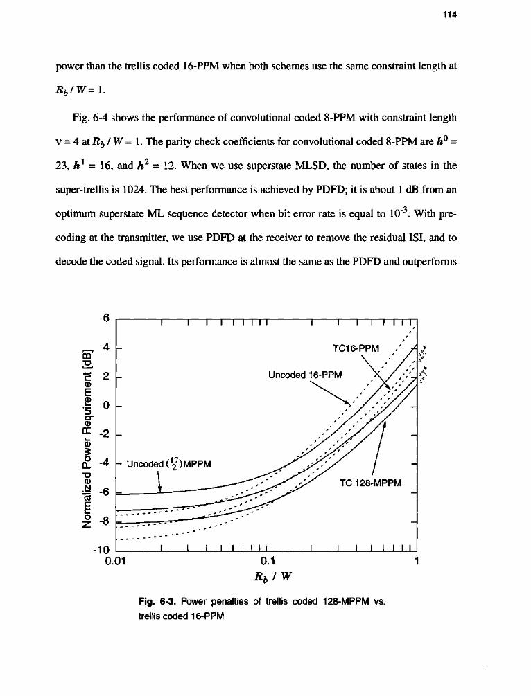
114
power than the trellis coded 16-PPM when both schemes use the same constraint length at
Rb/W=l.
Fig. 6-4 shows the performance of convolutional coded 8-PPM with constraint length
v = 4 at Rb IW = 1. The parity check coefficients for convolutional coded 8-PPM are h° =
23, hl = 16, and h2 = 12. When we use superstate MLSD, the number of states in the
super-trellis is 1024. The best performance is achieved by PDFD; it is about 1 dB from an
optimum superstate ML sequence detector when bit error rate is equal to 10~3. With pre-
coding at the transmitter, we use PDFD at the receiver to remove the residual ISI, and to
decode the coded signal. Its performance is almost the same as the PDFD and outperforms
4 CO -a * * c 2 CD E
ire
0 3 cr CD DC -? i _ CD £ o
CL -4 "O 0
liz
-6 CO
-8
-10
1 1—I I I I I I " I 1 — I I I I I
\- Uncoded(19
7)MPPM
TC16-PPM
Uncoded 16-PPM
J I I I I I I I
TC128-MPPM
0.01 0.1
Rb I W
Fig. 6-3. Power penalties of trellis coded 128-MPPM vs.
trellis coded 16-PPM
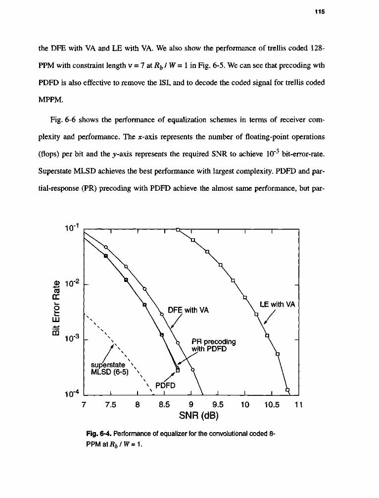
115
the DFE with VA and LE with VA. We also show the performance of trellis coded 128-
PPM with constraint length v = 7 at Rh IW = 1 in Fig. 6-5. We can see that precoding wth
PDFD is also effective to remove the ISI, and to decode the coded signal for trellis coded
MPPM.
Fig. 6-6 shows the performance of equalization schemes in terms of receiver com
plexity and performance. The #-axis represents the number of floating-point operations
(flops) per bit and the ^-axis represents the required SNR to achieve 10~3 bit-error-rate.
Superstate MLSD achieves the best performance with largest complexity. PDFD and par
tial-response (PR) precoding with PDFD achieve the almost same performance, but par-
LE with VA
Fig. 6-4. Performance of equalizer for the convolutional coded 8-
P P M a t i V W = 1 .

116
tial-response precoding with PDFD requires less complexity than that of PDFD. LE with
VA requires the least complexity but its performance is poor. Especially in our applica
tions, precoding at the transmitter and PDFD at the receiver is a good choice to perform
equalization and decoding simultaneously.
6.7 SUMMARY AND CONCLUSIONS
Superstate MLSD is an optimum way to jointly perform equalization and decoding for
coded signals in the presence of ISI. But its complexity is large even for short ISI chan
nels. First we compared performance of trellis-coded 128-MPPM and trellis coded 16-
10 -1
1 0-^ L PDFD S in-2 (U
rr i—
o 1—
LU
CO 10"3 \-
10 -4
N superstate \ MLSD (6-5)
\
PR precoding with PDFD
DFE with VA
6.5 7.5 8 8.5
SNR (dB)
LE with VA
9.5 10
Fig. 6-5. Performance of equalizer for the trellis coded 128-
MPPM at Rb IW = 1.

117
PPM using the superstate MLSD. The trellis coded 128-MPPM outperforms trellis coded
16-PPM when bit-rate-to-bandwidth ratio is large. We also compared the performance of
various equalization schemes for the coded signal. Precoding at the transmitter resulted in
a truncated ISI channel of memory one, which reduced the complexity of receiver signifi
cantly. Numerical result showed that partial-response precoding with PDFD is a good
choice for our applications in terms of both error probability and complexity.
10.5 -
1 1 1 1 1 1 1 1 1
•
LE with VA
1 1 1 1 1 1 1 1
s-10
2,
—
| 9.5 CO
- -
•a 2 9 DFE with VA
'Z3 cr <D DC 8.5
•
• • PDFD
8 -
PR precoding with PDFD
-
7.5
7 l M
Superstate m_ MLSD
1 1 1 1 1 1 1 1
10° 104
Receiver Flops 10£
Fig. 6-6. Complexity vs. performance for each equalization scheme using convolutional coded 8-PPM at Rb I W = 1; x-axis represents the number of floating-point operations (flops) per bit and^-axis represents the required SNR to achieve 10"3 BER.

118
CHAPTER 7
C O N C L U S I O N S A N D F U T U R E W O R K
7.1 CONCLUSIONS
This thesis has concentrated on the design of coded modulation and equalization for
high-speed wireless infrared communications with severe ISI. We proposed new trellis
codes based on MPPM and new equalization schemes.
Due to its unique channel characteristics, we had to reevaluate the relative perfor
mance of various modulation schemes. In chapter 2, we made comparisons of power effi
ciency and bandwidth efficiency for each candidate modulation scheme. It turned out that
MPPM and PPM are power-efficient modulation, and OOK and OPPM are bandwidth-
efficient. Calculating the power spectrum density confirmed our first-null approximation
119
for the bandwidth calculation. The MPPM bound provided the performance limit for
bandwidth and power efficiency of uncoded MPPM and its variants. It was shown that cer
tain MPPM can achieve the same bandwidth as OOK with 1.5 dB less power, or can
achieve the arbitrarily low power requirement with infinite bandwidth.
The performance comparisons of MPPM and its variants on ISI channels using several
equalization schemes were addressed in chapter 3. We proposed a new precoding scheme
compatible with the infrared channel. When we used DFE at the receiver to remove the
residual ISI, the proposed precoding scheme showed good performances in terms of both
complexity and error probability.
We calculated the achievable information rate and cutoff rate of MPPM and its vari
ants as theoretical performance limits in chapter 4.
When we combine coding with modulation, we can improve the overall power effi
ciency. We combined existing convolutional codes with PPM and developed a new trellis
coded MPPM in chapter 5. We performed a computer search for the parity check polyno
mials of trellis coded MPPM that gives a large minimum distance. We calculated an
approximation for the minimum distance and compared our results with the well-known
simplex bound. We calculated the power efficiency and bandwidth efficiency for coded
modulation schemes. Since poor bandwidth-efficient schemes are sensitive to multipath
distortion, we chose both power-efficient and bandwidth-efficient coded schemes such as
trellis coded 128-MPPM. We compared the performance of trellis coded 128-MPPM and
trellis coded 16-PPM using the superstate MLSD. Trellis coded 128-MPPM outperforms
trellis coded 16-PPM on a severe ISI channel. We showed that trellis coded 128-MPPM is

120
the most power-efficient scheme developed so far in indoor infrared channel, especially in
the face of severe multipath dispersion.
Although superstate MLSD is an optimum way to jointly perform equalization and
decoding for coded signals in the presence of ISI, its complexity is large even for short ISI
channels. We proposed suboptimal methods of equalization and decoding to reduce the
complexity in chapter 6. Conventional LE and DFE did not work well with the coded
signal. We proposed to use partial-response precoding at the transmitter and to use PDFD
at the receiver to equalize and to decode the coded signals, thus reducing the complexity
of the receiver significantly. Numerical result showed that the proposed partial-response
precoding scheme combined with PDFD is an effective solution for our application.
7.2 FUTURE WORK
7.2.1 Channel Capacity of Wireless Infrared Channel
An interesting problem is the calculation of the channel capacity of (1-1) under the
constraint of (1-2). The solution of this problem may lead to useful insight into the signal
set design problem. Consider an ideal AWGN channel with average amplitude input con
straint:
yk=xk+nh (7-1)
under the constraints x^ > 0 and Eix^} < P, and n^ is white Gaussian noise with variance
N0, and is assumed to be independent of x^. The average mutual information between the
channel input and output is [53]:
I(xk; yk) = H(yk) - H(yk I xk) = H(yk) - H(nk\ (7-2)

121
where the conditional entropy Hiy^ I x^) is equal to the noise entropy and independent of
input distribution. Thus, the problem of finding the capacity for an additive noise channel
reduces to maximize the output entropy Hiy^) subject to the input constraint:
c = max K } = max H(y ) _ H{ y ( 7 . 3 )
Px(*k) Px(xk)
Since yk=xk + nfa E{xk) -P implies E{y^} < P. The general strategy is to find^y^)
with jT ykPY^k) dyk < P to maximize H(y&), and then try to find an input distribution
px(xk) that yields /?yCy&). Finding a channel capacity reduces the problem of maximizing
entropy, H(yk) = J ^ pY(yk) \og\pY(yk)] dyk, over all pY(yk) satisfying:
pY(yk) ^ °> J l PYW dyk=\y and £ ykPY^k) dyk < p- 0~4)
The maximum entropy principle [36] implies that the maximum entropy is infinite, and
that there is no maximum entropy distribution. Therefore, the channel capacity under the
average amplitude constraint is infinite. We can show that the capacity of the multipath
channel is also infinite using the arguments similar to those in section 4.3. This result is
not surprising since the capacity of the Poisson channel under the same constraints is also
infinite [84].
There are several interesting questions arising from this result: (1) How can we
achieve the infinite channel capacity? (2) What is the optimum signal set for this channel?
(3) If it is impossible to achieve it, what are more practical constraints for the input? What
is channel capacity under the modified constraints? These questions still remain open.

122
7.2.2 Concatenated Codes
In section 5.2, we combined the convolutional code and PPM as shown Fig. 7-1-a.
Information bits with bit rate R^ enter the (log2L - 1) / log2L convolutional encoder. The
PPM encoder maps each block of log2L bits into one L-PPM codeword. The advantage of
this type of scheme is the use of low duty-cycle modulation, such as PPM, at the output of
the transmitter. But it has a poor bandwidth efficiency:
S / P log2L LPPM
(a)
H S / P L-1 PPM L - l C.C.
(b)
(c)
Fig. 7-1. Serial concatenated codes: (a) convolutional coded PPM, (b) PPM with convolutional code, (c) a systematic feedforward convolutional encoder for configuration (b).

123
Pi = Bandwidth
Tu log 2 L-l (7-5)
One possible modification of this scheme is exchange the order of convolutional
encoder and PPM mapper as shown in Fig. 7-1-b. Information bits with rate R^ enter the
(L - 1) PPM encoder, which maps each block of log2(Z/ - 1) bits into one of L - 1 PPM
codeword. The (L - 1) / L convolutional encoder transforms the L - 1 input bits into L
coded bits. The bandwidth efficiency of this configuration is:
P2 = Bandwidth Rl log2(L-l)
(7-6)
We can see that this configuration is more bandwidth efficient since the ratio of (7-5) to (7-
6) is:
(32 log2L-l
p! log2(L-l) <1 (7-7)
Table 7-1 lists the ratio fi^ I (32.
TABLE 7-1: The bandwidth-efficiency ratio between two serial concatenated schemes.
L Pi/fc 4 0.63
8 0.71
16 0.77
32 0.81

124
To maintain the low duty-cycle property of PPM, we can use a systematic feedforward
convolutional encoder as shown in Fig. 7-1-c. The weight of the output of the convolu-
tional encoder is only one or two depending on the value of x^0.
However, to handle a large number of alphabets, the (L - 1) / L convolutional encoder
should be high-rate. For example, the rates of convolutional encoder are 4/5, 8/9, and 16/
17 for 4, 8, 16-PPM, respectively, and the numbers of outgoing branches from each state
are 16, 256, 65536, respectively. Therefore, the use of high-rate convolutional codes with
Viterbi decoding becomes problematic. To avoid this complexity problem, we can use a
punctured convolutional code [85].
7.2.3 Turbo Codes
In 1993, Berrou et al. [86] reported a new class of code called turbo codes, whose per
formance in terms of BER was a few tenths of a dB from the Shannon limit. Since then,
many researchers have focused on the design and development of turbo codes. A turbo
encoder is based on a parallel concatenation of two recursive systematic convolutional
code and an interleaver. While TCM is a bandwidth-efficient scheme, turbo coding is a
power-efficient scheme. Surely, turbo codes are good candidates for wireless infrared
channel, where power efficiency is the most important parameter. However, the perfor
mance of turbo codes over a multipath channel is unknown.
7.2.4 Synchronization
In wireless infrared communications, highly peaked and narrow optical pulses are
used to achieve high power efficiency, but accurate timing synchronization is also required
for ideal detection. In this thesis, we have assumed perfect symbol synchronization. But

125
there exists a timing offset in any real system, and this offset influences the performance of
the receiver [87]. Consider first the OOK system where a timing error A (0 < A < 772)
exists, such that sampling occur at T + A. In Fig. 7-2, we show the four possible cases for
current symbol during interval [0, T) and the next symbol during [T, 2T). When a received
bits arrive, the matched filter convolves with only portions of the current pulse and also
with some portions of the next pulse, and sampling occurs at kT + A. Following the anal
ysis of [87], we can calculate the bit error rate for OOK considering all four cases in
Fig. 7-2:
Pr[bit error] = \Q{-^== 2 ^WoRi 2^ .V^Pi
_2A> TJ (7-8)
w rpppivpH bite w rpppivpH bite received bits
receiver clock
) I T i 2T o ! T \ IT received bits
receiver clock A T+A A T+A •
received bits
receiver clock
(a) (b)
A A 4 4
fc- received bits ) ; T \
T+A
2T^ '"" "~ (
• receiver clock
) | T | 2T
receiver clock A
T \
T+A
2T^ '"" "~ (
• receiver clock A T+A w
(c) (d)
Fig. 7-2. Effects of timing error for OOK when (a) current bit = 0 and next bit = 0, (b) current bit = 0 and next bit = 1, (c) current bit = 1 and next bit = 0, (d) current bit = 1 and next bit = 1.

126
When A —>0, the above expression reduces to (2-4). When A —>T I 2, the above expres
sion approaches to 1 / 2, and the system does not work at all.
Similarly, we can calculate the probability of symbol error for PPM when there exists
a timing error A, using the result of [87] and section 3.3:
*™<i'&-$r<>-«{,&-ii- "•" where Tc = T I L is the chip interval. We can derive a similar expression for the symbol
error probabilities of MPPM. However, the loss of orthogonality in MPPM may make this
calculation more difficult than PPM.
Georghiades and his students in Texas A & M university [88][89] have studied the
frame and symbol synchronization for MPPM and its variants on a Poisson channel. Their
results should be very helpful in a similar study for our channel.
7.2.5 System Implementation
As we indicated in section 1.1, most real systems have used OOK or PPM. But we
showed that theoretically, MPPM is a very good choice for both uncoded and coded mod
ulation schemes on a severe multipath channel. Both for academic and practical purposes,
complete system design and implementation of high-speed wireless infrared communica
tion using MPPM is very promising.

127
REFERENCES
[1] A. R. Tharek, "Indoor Communication and Other Applications at Millimeter-wave Band," IEEE Tencon' 90, pp. 241-245, 1990.
[2] M. J. McCullagh and D. R. Wisely, "155 Mb/s Optical Wireless Link Using a Bootstrapped Silicon APD Receiver," Electronic Letter, vol. 30, no. 5, pp. 430-432, 1994.
[3] Infrared Data Association (http://www.irda.org).
[4] J. M. Kahn and J. R. Barry, "Wireless Infrared Communications," Proceedings of the IEEE, vol. 85, no. 2, pp. 265-298, February 1997.
[5] Spectrix Corporation (http://www.spectrixcorp.com).
[6] G.W. Marsh and J. M. Kahn, "50-Mb/s Diffuse Infrared Free-Space Link Using On-Off Keying with Decision Feedback Equalization," IEEE International Symposium on Personal, Indoor and Mobile Radio Communications, pp. 1086-1089, 1994.
[7] F. R. Gfeller and U. Bapst, "Wireless In-House Data Communications via Diffuse Infrared Radiation," Proceeding of IEEE, vol. 67, no. 11, pp. 1474-1486, November 1979.
[8] M. D. Kotzin, "Short-Range Communications Using Diffusely Scattered Infrared Radiation," Ph.D. Dissertation, Northwestern University, Evanston, IL, June 1981.
[9] J. R. Barry, Wireless Infrared Communications, Kluwer Academic Publishers, 1994.
[10] J. R. Barry, J. M. Kahn, W. J. Krause, E. A. Lee, and D. G. Messerschmitt, "Simulation of Multipath Impulse Response for Wireless Optical Channels," IEEE
128
Journal of Selected Areas in Communication, vol. 11, no. 3, pp. 367-379, April 1993.
[11] J. M. Kahn, J. R. Barry, M. D. Audeh, J. B. Carruthers, W. Krause, and G. W. Marsh, "Non-Directed Infrared Links for High-Capacity Wireless LANs," IEEE Personal Communications Magazine, vol. 1, no. 2, pp. 12-25, Second Quarter 1994.
[12] J. M. Kahn, W. J. Krause, and J. B. Carruthers, "Experimental Characterization of Non-Directed Indoor Infrared Links," IEEE Transactions on Communications, vol.43, no. 2-4, pp. 1613-1623, February-April 1995.
[13] J. B. Carruthers and J. M. Kahn, "Modeling of Non-Directed Wireless Infrared Channels," IEEE International Conference on Communications, Dallas, Texas, pp. 1227-1231, June 1996.
[14] D. C. Lee, M. D. Audeh, and J. M. Kahn, "Trellis-coded Pulse-Position Modulation for Indoor Wireless Infrared Communications," IEEE International Symposium on Personal, Indoor and Mobile Radio Communications, pp. 349-353, Taipei, Taiwan, October 1996.
[15] M. D. Audeh, J. M. Kahn and J. R. Barry, "Performance of Pulse-Position Modulation on Measured Non-Directed Indoor Infrared Channels," IEEE Transaction on Communications, vol. 44, pp. 654-659, June 1996.
[16] M. D. Audeh, J.M. Kahn and J.R. Barry, "Decision-Feedback Equalization of Pulse-Position Modulation on Measured Non-Directed Indoor Infrared Channels", submitted, to IEEE Transaction on Communications, June 1996.
[17] M. D. Audeh, "Power-Efficient Modulation for High-Speed Non-Directed Infrared Communication," Ph.D. Dissertation, Univ. of California, Berkeley, 1995.
[18] H. Hashemi, G. Yung, M. Kavehrad, R. Behbahani and P. A. Galko, "Indoor Propagation Measurements at Infrared Frequencies for Wireless Local Area Networks Applications," IEEE Transaction on Vehicular Technology, vol. 43, pp. 562-576, August 1994.
[19] R. T. Valadas, "Interference Modeling for The simulation of IEEE 802.11 Infrared Local Area Networks," IEEE International Symposium on Personal, Indoor and Mobile Radio Communications, pp. 257-261, Taipei, October 1996.
[20] A. Papoulis, Probability, Random Variables, and Stochastic Processes, McGraw-Hill, 1984.
129
[21] J. R. Barry, "Sequence Detection and Equalization for Pulse-Position Modulation," IEEE International Conference on Communications, New Orleans, LA, pp. 1561-1565, May 1994.
[22] J. G. Proakis, Digital Communications, Third Edition, McGraw-Hill, 1995.
[23] R. D. Gitlin, J. F. Hayes, and S. B. Weinstein, Data Communication Principles, Plenum Press, 1992.
[24] J. R. Pierce, "Optical Channel: Practical limits with Photon Counting," IEEE Transactions on Communications, vol. 26, no. 12, pp. 1819-1821, December 1978.
[25] H. Sugiyama and K. Nosu, "MPPM: A method for improving the Band-Utilization Efficiency in Optical PPM," Journal of Lightwave Technology, vol 7, no. 3 pp. 465-472, March 1989.
[26] G. E. Atkin, K. S. Fung, "Coded Multipulse Modulation in Optical Communication System," IEEE Transactions on Communications, vol. 42, no. 2, pp. 574-582, February 1994.
[27] A. E. Brouwer, J. B. Shearer, N. J. A. Sloane, and W. D. Smith, "A New Table of Constant Weight Codes," IEEE Transactions on Information Theory, vol. 36, no. 6, pp. 1334-1380, November 1990.
[28] H. Park and J. R. Barry, "Modulation Analysis for Wireless Infrared Communication," IEEE International Conference on Communications, Seattle, WA, pp. 1182-1186, June 1995.
[29] D. Slepian, "Permutation Modulation," Proceedings of IEEE, vol. 53, pp. 228-236, March 1965.
[30] H. Park and J. R. Barry, "The Performance of Multiple Pulse-Position Modulation on Multipath Channels," IEE Proceedings, Optoelectronics, vol. 143, no. 6, pp. 360-364, December 1996.
[31] D. Slepian, "Group Codes for the Gaussian Channel," Bell Syst. Tech. J., vol. 47, pp. 575-602, April 1968.
[32] I. Bar-David and G. Kaplan, "Information Rates of Photon-limited Overlapping Pulse Position Modulation Channel," IEEE Transactions on Information Theory, vol. 30, no. 3, pp. 455-463, May 1984.

130
[33] F. Amoroso, "The Bandwidth of Digital Data Signals," IEEE Communications Magazine, vol. 18, pp. 13-24, November 1980.
[34] S. G. Wilson, Digital Modulation and Coding, Prentice-Hall, Inc., 1996.
[35] W. A. Gardner, Statistical Spectral Analysis: A Non-probabilistic Theory, Prentice-Hall, 1987.
[36] T. M. Cover and J. A. Thomas, Elements of Information Theory, John Wiley & Sons, 1991.
[37] G. D. Forney, Jr., "Maximum-likelihood Sequence Estimation of Digital Sequences in the Presence of Intersymbol Interference," IEEE Transactions on Information Theory, vol. 18, no. 3, pp. 363-377, May 1972.
[38] G. D. Forney, Jr., "The Viterbi Algorithm," Proceedings of IEEE, vol. 61, no. 3, pp. 268-278, March 1973.
[39] M. V. Eyuboglu and S. U. H. Qureshi, "Reduced-State Sequence Estimation with Set Partitioning and Decision Feedback," IEEE Transactions on Communication, vol. 36, no. 1, pp. 13-20, January 1988.
[40] M. V. Eyuboglu and S. U. H. Qureshi, "Reduced-State Sequence Estimation for Coded Modulation on Intersymbol Interference Channels," IEEE Journal of Selected Areas in Communication, vol. 7, no. 6, pp. 989-995, August 1989.
[41] A. Duel-Hallen and C Heegard, "Delayed Decision-Feedback Sequence Estimation," IEEE Transactions on Communication, vol. 37, no.5, pp. 428-436, May 1989.
[42] R. Price, "Nonlinearly Feedback Equalized PAM versus Capacity for Noisy Channel Filters," IEEE International Conference on Communications, pp. 22.12-22.17, 1972.
[43] K. Abend and B. D. Fritchman, "Statistical Detection for Communication Channels with Intersymbol Interference," Proceeding of IEEE, vol. 58, no. 5, pp. 799-785, May 1970.
[44] D. Williamson, R. A. Kennedy, and G. W. Pulford, "Block Decision Feedback equalization," IEEE Transactions on Communication, vol.40, no. 2, pp. 255-264, February 1992.

131
[45] M. Tomlinson, "New Automatic Equalizer Employing Modulo Arithmetic," Electronic Letters, vol. 7, no. 5/6, pp. 138-139, March 1971.
[46] H. Harashima and H. Miyakawa, "Matched Transmission Technique for Channels with Intersymbol Interference," IEEE Transactions on Communication, vol. 20, no. 4, pp. 774-780, August 1972.
[47] R. Laroia, S. A. Tretter, and N. Farvardin, "A Simple and Effective Precoding Scheme for Noise Whitening on Intersymbol Interference Channels," IEEE Transactions on Communication, vol. 41, no. 10, pp. 1460-1462, October 1993.
[48] R. Laroia, "Coding for Intersymbol Interference Channels - Combined Coding and Precoding," IEEE Transactions on Information Theory, vol. 42, no. 4, pp. 1053-1061, July 1996.
[49] C. N. Georghiades, "Modulation and Coding for Throughput-Efficient Optical Systems," IEEE Transactions on Information Theory, vol. 40, no.5, pp. 1313-1326, September 1994.
[50] S. Benedetto, E. Biglieri, and V. Castellani, Digital Transmission Theory, Prentice-Hall, Englewood Cliffs, NJ, 1987.
[51] E. A. Lee, D. G. Messerschmitt, Digital Communication, Second Edition, Klu-wer Academic Publishers, 1994.
[52] R. F. H. Fischer and J. B. Huber, "Comparison of Precoding Schemes for Digital Subscriber Lines," IEEE Transactions on Communication, vol. 45, no. 3, pp. 334-343, March 1997.
[53] R. G. Gallager, Information Theory and Reliable Communication, Wiley, 1968.
[54] J. G. Smith, "The Information Capacity of Amplitude and Variance-Constrained Scalar Gaussian Channels," Information and Control, vol. 18, pp. 203-219, 1971.
[55] B. S. Tsybakov, "Capacity of a Discrete Time Gaussian Channel with a Filter," Problemy Peredachi Informatsii, vol. 6, no. 3, pp. 78-82, July-September 1970.
[56] W. Hirt, "Capacity and Information Rates of Discrete-Time Channels with Memory," Ph.D. Dissertation, Swiss Federal Institute of Technology, Zurich, 1988.
[57] S. Shamai (Shitz), L. H. Ozarow, and A. D. Wyner, "Information Rates for a Discrete-Time Gaussian Channel with Intersymbol Interference and Stationary

132
Inputs," IEEE Transactions on Information Theory, vol. 37, no. 6, pp. 1527-1539, November 1991.
[58] R. E. Blahut, Principles and Practice of Information Theory, Reading, MA, Add-ison-Wesley, 1987.
[59] J. L. Massey, "Coding and Modulation in Digital Communication," Proc. Int. Ziirich Seminar on Digital Communications, Switzerland, E2 1-4, March 1974.
[60] E. Biglieri, "The Computational Cutoff Rate of Channels Having Memory," IEEE Transactions on Information Theory, Vol. 27, No. 3, pp. 352-357, May 1981.
[61] R. A. Horn, and C. A. Johnson, Matrix Analysis, Cambridge University Press, 1985.
[62] A. J. Viterbi, and J. K. Omura, Principles of Digital Communication and Coding, McGraw-Hill Book Company, New York, 1979.
[63] H. Park and J. R. Barry, "Performance Analysis and Channel Capacity of Multiple Pulse-Position Modulation on Multipath Channels," IEEE International Symposium on Personal, Indoor and Mobile Radio Communications, pp. 247-251, Taipei, October 1996.
[64] G. Ungerboeck, "Channel Coding with Multilevel / Phase Signals," IEEE Transactions on Information Theory, vol. 28, no. 1, pp. 55-67, January 1982.
[65] A. R. Calderbank and N. J. A. Sloane, "New Trellis Codes Based on Lattice and Cosets," IEEE Transactions on Information Theory, vol. 32, no. 2, pp. 177-195, March 1987.
[66] E. Zehavi and J. K. Wolf, "On the Performance Evaluation of Trellis Codes," IEEE Transactions on Information Theory, vol. 33, no. 2, pp. 196-202, March 1987.
[67] S. Benedetto, M. Mondin, and G. Montorsi, "Performance Evaluation of Trellis Coded Modulation Schemes," Proceedings of IEEE, vol. 82, no. 6, pp. 833-855, June 1994.
[68] F. Wang and D. J. Costello, "Probabilistic Construction of Large Constraint Length Trellis Codes for Sequential Decoding," IEEE Transactions on Communication, vol. 43, no. 9, pp.2439-2447, September 1995.

133
[69] E. Biglieri, D. Divsalar, P. McLane, and M. Simon, Introduction to Trellis-coded Modulation with Applications, Mcmillan, 1991.
[70] E. Forestieri, R. Gangopadhyay, and G. Prati, "Performance of Convolutional Codes in a Direct-Detection Optical PPM Channel," IEEE Transactions on Communications, vol. 37, no. 12, pp. 1303-13, December 1989.
[71] C. N. Georghiades, "Some Implications of TCM for Optical Direct-Detection Channels," IEEE Transactions on Communications, vol. 37, no.5, pp. 481-487, May 1989.
[72] G. J. Pottie, "Trellis Codes for the Optical Direct-Detection Channel," IEEE Transactions on Communications, vol. 39, no. 8, pp. 1182-1183, August 1991.
[73] J. A. Heller, "Sequential Decoding: Sort Constraint Length Convolutional Code," JPL Space Program Summary, 37-54, vol 3, pp. 171-177, December 1967.
[74] A. R. Calderbank, J. E. Mazo, and V. K. Wei, "Asymptotic Upper Bounds on the Minimum Distance of Trellis Codes," IEEE Transactions on Communication, Vol. 33, No. 4, pp. 305-309, April 1985.
[75] S. Lin and D. J. Costello, Error Control Coding: Fundamentals and Applications, Prentice-Hall, 1983.
[76] G. L. Bechtel and J. W. Modestino, "Pulsewidth-constrained Signaling and Trellis-coded Modulation on the Direct-detection Optical Channel," IEEE Global Telecommunications Conference, vol. 2, pp. 842-847, 1988.
[77] P. R. Chevillat and E. Eleftheriou, "Decoding of Trellis-Encoded Signals in the Presence of Intersymbol Interference and Noise," IEEE Transactions on Communication, vol. 37, no. 7, pp. 669-676, July 1989.
[78] I. Oka and E. Biglieri, "Error Probability Bounds for Trellis Coded Modulation over Sequence Dependent Channels," The Transactions of IEICE, vol. E72, no. 4, pp. 375-382, April 1989.
[79] J. E. Porath, "On Trellis-coded Modulation for Gaussian and Band-limited Channels," Tech. Rep. 221, Chalmers University of Technology, Goteborg, Sweden, 1991.
[80] K. Wesolowski, "Efficient Digital Receiver Structure for Trellis-coded Signals Transmitted through Channels with Intersymbol Interference," Electronic Letters, vol. 23, no. 24, pp. 1265-1267, November 1987.

134
[81] H. K. Thapar, "Real-Time Application of Trellis Coding to High-Speed Voice-band Data Transmission," IEEE Journal of Selected Areas in Communications, vol. 2, no. 5, pp. 648-658, September 1984.
[82] L. N. Wong and P. J. Mclane, "Performance of Trellis Codes for a Class of Equalized ISI Channels," IEEE Transactions on Communication, vol. 36, no. 12, pp. 1330-1336, December 1988.
[83] G. D. Forney Jr. and M. V. Eyuboglu, "Combined Equalization and Coding Using Precoding," IEEE Communications Magazine, pp. 25-34, December 1991.
[84] M. H. A. Davis, "Capacity and Cutoff Rate for Poisson-type Channels," IEEE Transactions on Information Theory, vol. 26, no. 6, pp. 710-715, November 1980.
[85] J. B. Cain, G. C. Clark, Jr., and J. M. Geist, "Punctured Convolutional Codes of Rate (n-\) I n and Simplified Maximum Likelihood Decoding," IEEE Transactions on Information Theory, vol. 25, pp. 97-100, January 1979.
[86] C. Berrou, A. Glavieux, and P. Thitimajshima, "Near Shannon Limit Error-correcting Coding and Decoding: Turbo-codes," IEEE International Conference on Communications, Geneva, Switzerland, pp. 1064-1070, May 1993.
[87] R. M. Gagliardi and S. Karp, Optical Communications, Second Edition, John Wiley & Sons, Inc., 1995.
[88] S. Patarasen and C. N. Georghiades, "Maximum-Likelihood Symbol Synchronization and detection of OPPM Sequences," IEEE Transactions on Communication, vol. 42, no. 6, pp. 2282-2290, June 1994.
[89] R. Velidi and C. N. Georghiades, "Frame Synchronization for Optical Multi-Pulse Pulse-Position Modulation, IEEE Transactions on Communication, vol. 43, no. 2-4, pp. 1838-1843, April 1995.
135
Vita
Hyuncheol Park was born in Pusan, Korea on June 7, 1960 and grew up in Seoul,
Korea. He received B.S. and M.S. both in Electronics Engineering from Yonsei University,
Seoul, Korea in 1983 and 1985, respectively, and Ph.D. in Electrical Engineering from
Georgia Institute of Technology, Atlanta, USA in 1997. From 1985 to 1991, he was a
research engineer in Samsung Electronics Co, Suwon, Korea where he developed the
broadcast satellite receivers, microwave low-noise amplifiers, and automatic vehicle mon
itoring systems. From 1992 to 1997, he was a graduate research assistant in Georgia Insti
tute of Technology, Atlanta, USA. His current research interests include coded
modulations, wireless infrared communications, and information theory.