
Coded Focal Stack Photography - MIT Media...
9
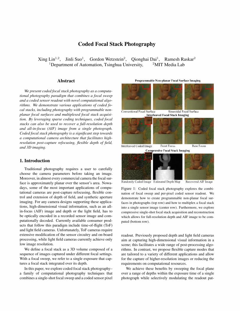
Coded Focal Stack Photography Xing Lin 1,2 , Jinli Suo 1 , Gordon Wetzstein 2 , Qionghai Dai 1 , Ramesh Raskar 2 1 Department of Automation, Tsinghua University, 2 MIT Media Lab Abstract We present coded focal stack photography as a computa- tional photography paradigm that combines a focal sweep and a coded sensor readout with novel computational algo- rithms. We demonstrate various applications of coded fo- cal stacks, including photography with programmable non- planar focal surfaces and multiplexed focal stack acquisi- tion. By leveraging sparse coding techniques, coded focal stacks can also be used to recover a full-resolution depth and all-in-focus (AIF) image from a single photograph. Coded focal stack photography is a significant step towards a computational camera architecture that facilitates high- resolution post-capture refocusing, flexible depth of field, and 3D imaging. 1. Introduction Traditional photography requires a user to carefully choose the camera parameters before taking an image. Moreover, in almost every commercial camera the focal sur- face is approximately planar over the sensor’s area. Nowa- days, some of the most important applications of compu- tational cameras are post-capture refocusing, flexible con- trol and extension of depth of field, and synthetic aperture imaging. For any camera designs supporting these applica- tions, high-dimensional visual information, such as an all- in-focus (AIF) image and depth or the light field, has to be optically encoded in a recorded sensor image and com- putationally decoded. Currently available consumer prod- ucts that follow this paradigm include time-of-flight (ToF) and light field cameras. Unfortunately, ToF cameras require extensive modification of the sensor circuitry and on-board processing, while light field cameras currently achieve only low image resolution. We define a focal stack as a 3D volume composed of a sequence of images captured under different focal settings. With a focal sweep, we refer to a single exposure that cap- tures a focal stack integrated over its depth. In this paper, we explore coded focal stack photography– a family of computational photography techniques that combines a single-shot focal sweep and a coded sensor pixel Figure 1: Coded focal stack photography explores the combi- nation of focal sweep and per-pixel coded sensor readout. We demonstrate how to create programmable non-planar focal sur- faces in photographs (top row) and how to multiplex a focal stack into a single sensor image (center row). Furthermore, we explore compressive single-shot focal stack acquisition and reconstruction which allows for full-resolution depth and AIF image to be com- puted (bottom row). readout. Previously proposed depth and light field cameras aim at capturing high-dimensional visual information in a scene; this facilitates a wide range of post-processing algo- rithms. In contrast, we propose flexible capture modes that are tailored to a variety of different applications and allow for the capture of higher-resolution images or reducing the requirements on computational resources. We achieve these benefits by sweeping the focal plane over a range of depths within the exposure time of a single photograph while selectively modulating the readout pat-
Transcript of Coded Focal Stack Photography - MIT Media...
Coded Focal Stack Photography
Xing Lin1,2, Jinli Suo1, Gordon Wetzstein2, Qionghai Dai1, Ramesh Raskar2
1Department of Automation, Tsinghua University, 2MIT Media Lab
Abstract
We present coded focal stack photography as a computa-tional photography paradigm that combines a focal sweepand a coded sensor readout with novel computational algo-rithms. We demonstrate various applications of coded fo-cal stacks, including photography with programmable non-planar focal surfaces and multiplexed focal stack acquisi-tion. By leveraging sparse coding techniques, coded focalstacks can also be used to recover a full-resolution depthand all-in-focus (AIF) image from a single photograph.Coded focal stack photography is a significant step towardsa computational camera architecture that facilitates high-resolution post-capture refocusing, flexible depth of field,and 3D imaging.
1. Introduction
Traditional photography requires a user to carefullychoose the camera parameters before taking an image.Moreover, in almost every commercial camera the focal sur-face is approximately planar over the sensor’s area. Nowa-days, some of the most important applications of compu-tational cameras are post-capture refocusing, flexible con-trol and extension of depth of field, and synthetic apertureimaging. For any camera designs supporting these applica-tions, high-dimensional visual information, such as an all-in-focus (AIF) image and depth or the light field, has tobe optically encoded in a recorded sensor image and com-putationally decoded. Currently available consumer prod-ucts that follow this paradigm include time-of-flight (ToF)and light field cameras. Unfortunately, ToF cameras requireextensive modification of the sensor circuitry and on-boardprocessing, while light field cameras currently achieve onlylow image resolution.
We define a focal stack as a 3D volume composed of asequence of images captured under different focal settings.With a focal sweep, we refer to a single exposure that cap-tures a focal stack integrated over its depth.
In this paper, we explore coded focal stack photography–a family of computational photography techniques thatcombines a single-shot focal sweep and a coded sensor pixel
Figure 1: Coded focal stack photography explores the combi-nation of focal sweep and per-pixel coded sensor readout. Wedemonstrate how to create programmable non-planar focal sur-faces in photographs (top row) and how to multiplex a focal stackinto a single sensor image (center row). Furthermore, we explorecompressive single-shot focal stack acquisition and reconstructionwhich allows for full-resolution depth and AIF image to be com-puted (bottom row).
readout. Previously proposed depth and light field camerasaim at capturing high-dimensional visual information in ascene; this facilitates a wide range of post-processing algo-rithms. In contrast, we propose flexible capture modes thatare tailored to a variety of different applications and allowfor the capture of higher-resolution images or reducing therequirements on computational resources.
We achieve these benefits by sweeping the focal planeover a range of depths within the exposure time of a singlephotograph while selectively modulating the readout pat-
terns of each pixel. This approach is shown to allow for in-teresting all-optical effects, such as programmable uncon-ventional and non-planar focal surfaces (Fig. 1, top row).Alternatively, the focal stack can be multiplexed into a sen-sor image and reconstructed using sampling and interpola-tion techniques inspired by the color de-mosaicing method(Fig. 1, center row). We also introduce compressive fo-cal stack photography, where a coded projection of the fo-cal stack is acquired and used to reconstruct the depth andall-in-focus image through sparse coding (Fig. 1, bottomrow). An overview of our coded focal stack photographyapproach is shown in Fig. 2.
In particular, we make the following contributions:
• We introduce coded focal stack photography as a com-bination of a focal sweep and a coded sensor readout.We show how this approach facilitates new applica-tions, including programmable non-planar focal sur-face imaging and interleaved focal stack acquisition.
• We propose compressive focal stack photography, anapproach that exploits sparsity in focal stack for re-covering a full-resolution depth and AIF image from asingle sensor image.
• We evaluate our computational camera architecture insimulation and build a prototype implementation.
2. Related WorkDepth from Focus/Defocus (DFF/DFD). DFF/DFD is aclass of techniques that use defocus cues to infer scenedepth. These methods have been studied extensively overpast decades (e.g, [7]). Usually, DFF determines the lo-cal depth according to the focus setting of highest sharp-ness in the focal stack [21]; a large number of defocusedimages is required to ensure sufficient reconstruction accu-racy. DFD infers scene depth from the amount of blur usinga single [19] or multiple [6] defocused images. Accuracy ofdepth estimation from a single image is limited due to theintrinsic ambiguity in depth inference. Hence, most DFDalgorithms require two or more images. In Section 4, weintroduce a mathematical framework to robustly reconstructimage and depth from the single coded image.
Light Field Imaging. Light field imaging has been ac-tively investigated for decades [2]. Ng et al. [22], for in-stance, built a hand-held plenoptic camera by attaching mi-crolenses to the sensor. Levoy et al. [17] extended thatsystem to microscopic imaging. Alternatives to microlens-based cameras include mask-based architectures [25] andcoded apertures [18]. All of these approaches either reduceimage resolution to multiplex the 4D light field onto the 2Dsensor or require multiple images. The main application oflight fields is flexible depth of field control. We demon-strate that one application of coded focal stack photography
achieves high-resolution, single-shot image refocus, as wellas the direct acquisition of programmable unconventionalfocal surfaces.
Image and Depth from a Single Exposure. A variety ofcomputational photography methods have been proposed toobtain depth and AIF image with single exposure. Usually,the point spread function of an optical system is modified tobecome depth-independent. This can be achieved using fo-cal sweep [14], apertures coded with diffusion [5] or chro-matic lens aberration [4]. In a post-processing step, AIFimage is computed by inverting the depth-independent blur.Lattice-focal lens [16] and coded apertures [15, 25, 3] havealso been explored for the purpose of recovering a depthmap with an AIF image. With coded focal stack photogra-phy, we combine focal sweep and coded sensor readout fornovel applications such as programmable unconventionalfocal surface imaging, multiplexed focal stack acquisition,and high-resolution AIF image and depth estimation.
Focal Stack Photography. Focal stack is a common toolin medical and scientific imaging, such has microscopy.Usually, the slices of a focal stack are combined to createa single AIF image. Hasinoff and Kutulakos [11] analyzedthe optimal settings for focus and aperture to minimize thenumber of required photographs for a given depth range.The combination of focal stack capture and varying aper-ture sizes has also been shown to allow for the reconstruc-tion of depth information [10]. In this paper, we exploresingle-shot coded focal stack approaches that have a varietyof different applications.
Per-pixel Coded Exposure. Per-pixel coded exposurephotography has been utilized in many applications, includ-ing high dynamic range (HDR) imaging, feature detection,object recognition [20], high-speed imaging, HDR imag-ing, and image deblurring [8], as well as for flexible spatio-temporal resolution tradeoffs [9]. Our application utilizes acoded per-pixel readout or modulation throughout the expo-sure time of a single photograph.
Compressive Computational Photography. Exploitingthe intrinsic redundancy of visual information to build next-generation computational imaging systems is an active areaof research in computational photography. Recently pro-posed methods include the reconstruction of short videoclips from a single coded image [12, 24, 23, 13] using com-pressive sensing paradigms. Usually, these include ran-domly coded image acquisition followed by sparse recon-struction. In one of our applications, we show that the pix-els within a focal stack are highly redundant and proposea novel method to acquire a single coded projection fromwhich the high-resolution focal stack is reconstructed usingsparse coding.
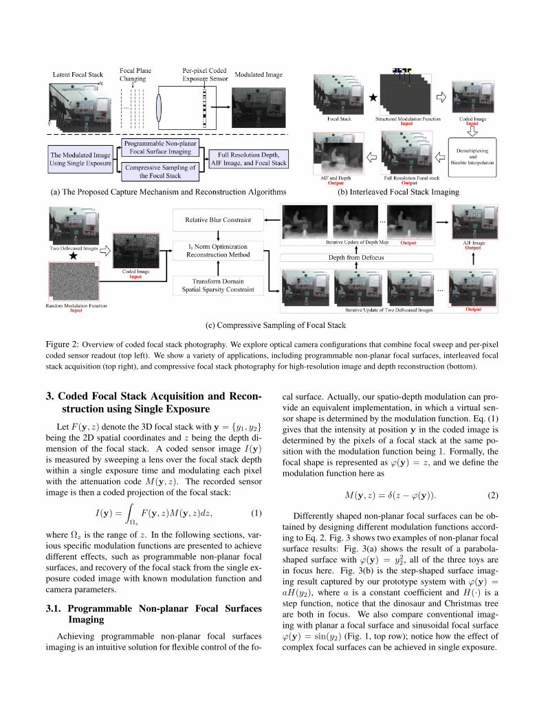
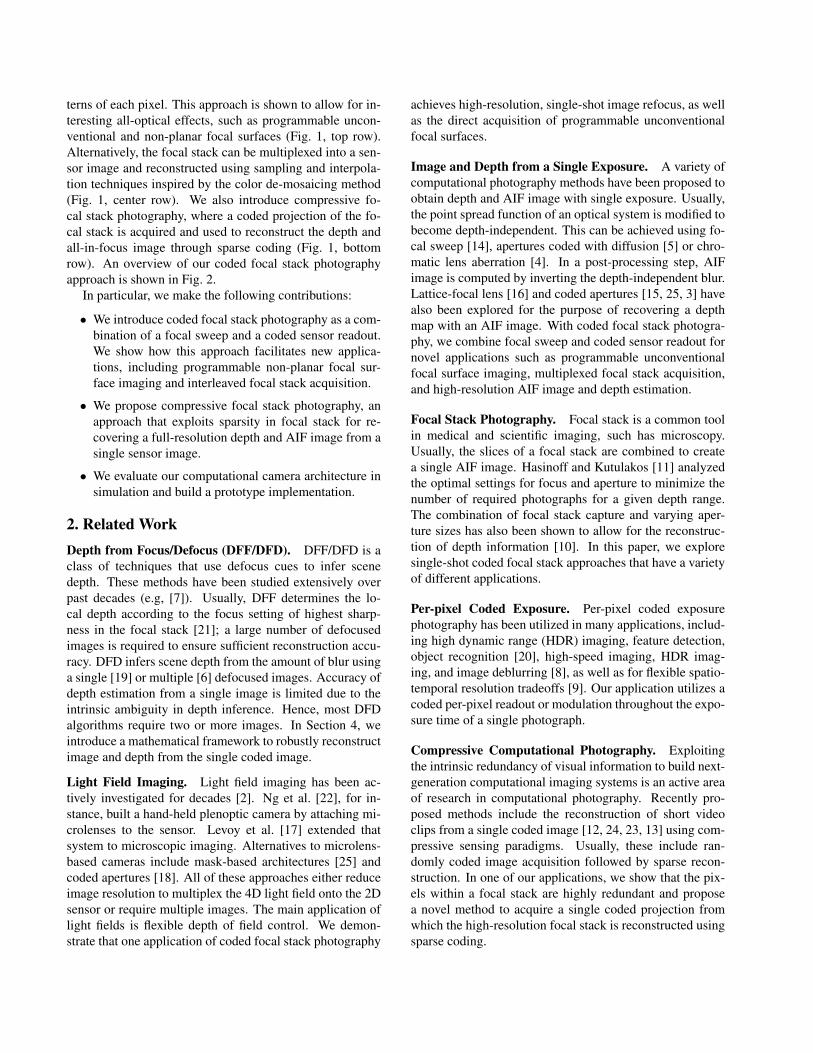
Figure 2: Overview of coded focal stack photography. We explore optical camera configurations that combine focal sweep and per-pixelcoded sensor readout (top left). We show a variety of applications, including programmable non-planar focal surfaces, interleaved focalstack acquisition (top right), and compressive focal stack photography for high-resolution image and depth reconstruction (bottom).
3. Coded Focal Stack Acquisition and Recon-struction using Single Exposure
Let F (y, z) denote the 3D focal stack with y = y1, y2being the 2D spatial coordinates and z being the depth di-mension of the focal stack. A coded sensor image I(y)is measured by sweeping a lens over the focal stack depthwithin a single exposure time and modulating each pixelwith the attenuation code M(y, z). The recorded sensorimage is then a coded projection of the focal stack:
I(y) =
∫Ωz
F (y, z)M(y, z)dz, (1)
where Ωz is the range of z. In the following sections, var-ious specific modulation functions are presented to achievedifferent effects, such as programmable non-planar focalsurfaces, and recovery of the focal stack from the single ex-posure coded image with known modulation function andcamera parameters.
3.1. Programmable Non-planar Focal SurfacesImaging
Achieving programmable non-planar focal surfacesimaging is an intuitive solution for flexible control of the fo-
cal surface. Actually, our spatio-depth modulation can pro-vide an equivalent implementation, in which a virtual sen-sor shape is determined by the modulation function. Eq. (1)gives that the intensity at position y in the coded image isdetermined by the pixels of a focal stack at the same po-sition with the modulation function being 1. Formally, thefocal shape is represented as ϕ(y) = z, and we define themodulation function here as
M(y, z) = δ(z − ϕ(y)). (2)
Differently shaped non-planar focal surfaces can be ob-tained by designing different modulation functions accord-ing to Eq. 2. Fig. 3 shows two examples of non-planar focalsurface results: Fig. 3(a) shows the result of a parabola-shaped surface with ϕ(y) = y2
2 , all of the three toys arein focus here. Fig. 3(b) is the step-shaped surface imag-ing result captured by our prototype system with ϕ(y) =aH(y2), where a is a constant coefficient and H(·) is astep function, notice that the dinosaur and Christmas treeare both in focus. We also compare conventional imag-ing with planar a focal surface and sinusoidal focal surfaceϕ(y) = sin(y2) (Fig. 1, top row); notice how the effect ofcomplex focal surfaces can be achieved in single exposure.
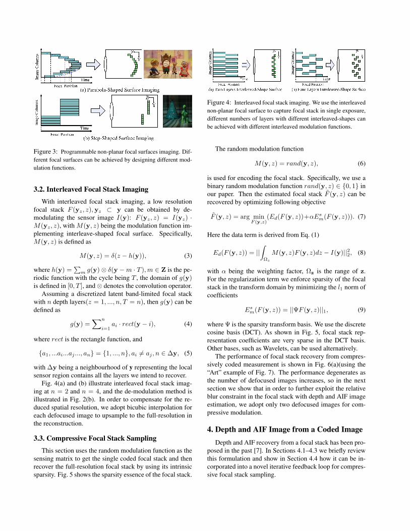
Figure 3: Programmable non-planar focal surfaces imaging. Dif-ferent focal surfaces can be achieved by designing different mod-ulation functions.
3.2. Interleaved Focal Stack Imaging
With interleaved focal stack imaging, a low resolutionfocal stack F (yz, z),yz ⊂ y can be obtained by de-modulating the sensor image I(y): F (yz, z) = I(yz) ·M(yz, z), with M(y, z) being the modulation function im-plementing interleave-shaped focal surface. Specifically,M(y, z) is defined as
M(y, z) = δ(z − h(y)), (3)
where h(y) =∑m g(y)⊗ δ(y −m · T ),m ∈ Z is the pe-
riodic function with the cycle being T , the domain of g(y)is defined in [0, T ], and ⊗ denotes the convolution operator.
Assuming a discretized latent band-limited focal stackwith n depth layers(z = 1, ..., n, T = n), then g(y) can bedefined as
g(y) =∑n
i=1ai · rect(y − i), (4)
where rect is the rectangle function, and
a1, ...ai...aj ..., an = 1, ..., n, ai 6= aj , n ∈ ∆y, (5)
with ∆y being a neighbourhood of y representing the localsensor region contains all the layers we intend to recover.
Fig. 4(a) and (b) illustrate interleaved focal stack imag-ing at n = 2 and n = 4, and the de-modulation method isillustrated in Fig. 2(b). In order to compensate for the re-duced spatial resolution, we adopt bicubic interpolation foreach defocused image to upsample to the full-resolution inthe reconstruction.
3.3. Compressive Focal Stack Sampling
This section uses the random modulation function as thesensing matrix to get the single coded focal stack and thenrecover the full-resolution focal stack by using its intrinsicsparsity. Fig. 5 shows the sparsity essence of the focal stack.
Figure 4: Interleaved focal stack imaging. We use the interleavednon-planar focal surface to capture focal stack in single exposure,different numbers of layers with different interleaved-shapes canbe achieved with different interleaved modulation functions.
The random modulation function
M(y, z) = rand(y, z), (6)
is used for encoding the focal stack. Specifically, we use abinary random modulation function rand(y, z) ∈ 0, 1 inour paper. Then the estimated focal stack F (y, z) can berecovered by optimizing following objective
F (y, z) = arg minF (y,z)
(Ed(F (y, z))+αEsm(F (y, z))). (7)
Here the data term is derived from Eq. (1)
Ed(F (y, z)) = ||∫
Ωz
M(y, z)F (y, z)dz − I(y)||22, (8)
with α being the weighting factor, Ωz is the range of z.For the regularization term we enforce sparsity of the focalstack in the transform domain by minimizing the l1 norm ofcoefficients
Esm(F (y, z)) = ||ΨF (y, z)||1, (9)
where Ψ is the sparsity transform basis. We use the discretecosine basis (DCT). As shown in Fig. 5, focal stack rep-resentation coefficients are very sparse in the DCT basis.Other bases, such as Wavelets, can be used alternatively.
The performance of focal stack recovery from compres-sively coded measurement is shown in Fig. 6(a)(using the“Art” example of Fig. 7). The performance degenerates asthe number of defocused images increases, so in the nextsection we show that in order to further exploit the relativeblur constraint in the focal stack with depth and AIF imageestimation, we adopt only two defocused images for com-pressive modulation.
4. Depth and AIF Image from a Coded ImageDepth and AIF recovery from a focal stack has been pro-
posed in the past [7]. In Sections 4.1–4.3 we briefly reviewthis formulation and show in Section 4.4 how it can be in-corporated into a novel iterative feedback loop for compres-sive focal stack sampling.
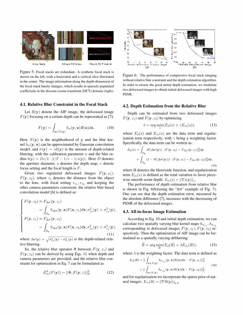
Figure 5: Focal stacks are redundant. A synthetic focal stack isshown on the left, with a horizontal and a vertical slice illustratedin the center. The image information along the depth-dimension ofthe focal stack barely changes, which results in sparsely populatedcoefficients in the discrete cosine transform (DCT) domain (right).
4.1. Relative Blur Constraint in the Focal Stack
Let R(y) denote the AIF image, the defocused imageF (y) focusing on a certain depth can be represented as [7]:
F (y) =
∫x∈N(y)
hσ(y,x)R(x)dx. (10)
Here N(y) is the neighborhood of y and the blur ker-nel hσ(y,x) can be approximated by Gaussian convolutionmodel, and σ(y) = κb(y) is the amount of depth-relatedblurring, with the calibration parameter κ and the blur ra-dius b(y) = Dv/2 · |1/F − 1/v − 1/s(y)|. Here D denotesthe aperture diameter, s denotes the depth map, v denotefocus setting and the focal length is F .
Given two registered defocused images F (y, z1),F (y, z2), where zi denotes the distance from the objectto the lens, with focal setting vz1 , vz2 and keeping theother camera parameters consistent, the relative blur basedconvolution model [6] is defined as:
F (y, z2) ≈ F∆σ(y, z1)
=
∫Ωx
h∆σ(y,x)F (x, z1)dx, σ2z2(y) > σ2
z1(y),
F (y, z1) ≈ F∆σ(y, z2)
=
∫Ωx
h∆σ(y,x)F (x, z2)dx, σ2z2(y) < σ2
z1(y),
(11)where ∆σ(y) =
√σ2z2
(y)− σ2z1
(y) is the depth-related rela-tive blurring.
So, the relative blur operator Φ between F (y, z1) andF (y, z2) can be derived by using Eqs. 11 when depth andcamera parameters are provided, and the relative blur con-straint for optimization in Eq. 7 can be formulated as
Edm(F (y)) = ||ΦzF (y, z)||22. (12)
Figure 6: The performance of compressive focal stack imagingwithout relative blur constraint and the depth estimation algorithm.In order to ensure the good initial depth estimation, we modulatetwo defocused images to obtain initial defocused images with highPSNR.
4.2. Depth Estimation from the Relative Blur
Depth can be estimated from two defocused imagesF (y, z1) and F (y, z2) by optimizing
s = arg mins
(Ed(s) + γEm(s)), (13)
where Ed(s) and Em(s) are the data term and regular-ization term respectively, with γ being a weighting factor.Specifically, the data term can be written as:
Ed(s) =
∫Ωy
H(∆σ(y)) · |F (y, z2)− F∆σ(y, z1)|22dy
+
∫Ωy
(1−H(∆σ(y))) · |F (y, z1)− F∆σ(y, z2)|22dy,
(14)where H denotes the Heaviside function, and regularizationterm Em(s) is defined as the total variation to favor piece-wise smooth scene depth: Em(s) = ||∇s(y)||1.
The performance of depth estimation from relative bluris shown in Fig. 6(b)(using the “Art” example of Fig. 7).One can see that the depth estimation error, measured bythe absolute difference [7], increases with the decreasing ofPSNR of the defocused images.
4.3. All-in-focus Image Estimation
According to Eq. 10 and initial depth estimation, we cancalculate two spatially varying blur kernel maps hσz1
, hσz2
corresponding to defocused images F (y, z1), F (y, z2) re-spectively. Then the optimization of AIF image can be for-mulated as a spatially varying deblurring:
R = arg minR
(Ed(R) + λEm(R)), (15)
where λ is the weighting factor. The data term is defined as
Ed(R) = ||∫x∈N(y)
hσz1 (y,x)R(x)dx− F (y, z1)||22
+ ||∫x∈N(y)
hσz2 (y,x)R(x)dx− F (y, z2)||22,(16)
and for regularization we incorporate the sparse prior of nat-ural images: Em(R) = ||∇R(y)||0.8.
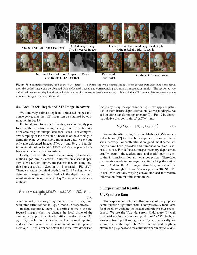
Figure 7: Simulated reconstruction of the “Art” dataset. We synthesize two defocused images from ground truth AIF image and depth,then the coded image can be obtained with defocused images and corresponding two random modulation masks. The recovered twodefocused images and depth with and without relative blur constraint are shown above, with which the AIF image is also recovered and therefocused images can be synthesized.
4.4. Focal Stack, Depth and AIF Image Recovery
We iteratively estimate depth and defocused images untilconvergence, then the AIF image can be obtained by opti-mization in Eq. 15.
For interleaved focal stack imaging, we can directly per-form depth estimation using the algorithm in Section 4.2after obtaining the interpolated focal stack. For compres-sive sampling of the focal stack, because of the difficulty indemultiplexing compressively modulated data, we encodeonly two defocused images B(y, z1) and B(y, z2) at dif-ferent focal settings for high PSNR and also propose a feed-back scheme to increase robustness.
Firstly, to recover the two defocused images, the demod-ulation algorithm in Section 3.3 utilizes only spatial spar-sity, so we further improve the performance by using rela-tive blur constraint in Section 4.1 (illustrated in Fig. 2(c)).Then, we obtain the initial depth from Eq. 13 using the twodefocused images and then feedback the depth constraintregularization into optimization Eq. 7 to get a better demod-ulation:
F (y, z) = arg minF (y,z)
(Ed(F ) + αEsm(F ) + βEdm(F )),
(17)where α and β are weighting factors, z = z1, z2, andwith three terms defined in Eqs. 8, 9 and 12 respectively.
In data capturing, there is a scaling between the de-focused images when we change the focal plane of thecamera, we approximate it with affine transformation [7]:y2 = ay1 + b. For calibration, we keep a small apertureand use four markers in the scene to calibrate the param-eters a,b. Thus, after we obtain the initial two defocused
images by using the optimization Eq. 7, we apply registra-tion to them before depth estimation. Correspondingly, weadd an affine transformation operator T to Eq. 17 by chang-ing relative blur constraint Edm(B(y)) into
Edm(F (y)) = ||ΦzTzF (y, z)||22. (18)
We use the Alternating Direction Method(ADM) numer-ical solution [27] to solve both depth estimation and focalstack recovery. For depth estimation, good initial defocusedimages have been provided and numerical solution is ro-bust to noise. For defocused images recovery, depth errorsusually occur in the textless areas and spatial sparsity con-straint in transform domain helps correction. Therefore,the iterative tends to converge in spite lacking theoreticalproof. And for the AIF image estimation, we extend theIterative Re-weighted Least Squares process (IRLS) [15]to deal with spatially varying convolution and incorporateinformation from multiple input images.
5. Experimental Results
5.1. Synthetic Data
This experiment tests the effectiveness of the proposeddemultiplexing algorithm from a compressively modulatedfocal stack by utilizing the spatial and relative blur redun-dancy. We use the “Art” data from Middlebury [1] withits spatial resolution down sampled to 695×555 pixels, asshown in two top left subfigures of Fig. 7. Empirically, weassume the depth range to be 2m ∼5m, the focal length be50mm, the f/# be 8 and the calibration parameter κ = 3e4.
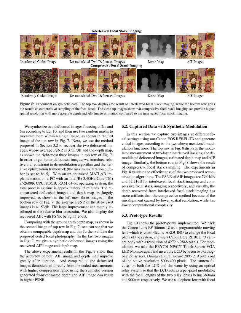
Figure 8: Experiment on synthetic data. The top row displays the result on interleaved focal stack imaging, while the bottom row givesthe results on compressive sampling of the focal stack. The close-up images show that compressive focal stack imaging can provide higherspatial resolution with more accurate depth and AIF image estimation compared to the interleaved focal stack imaging.
We synthesize two defocused images focusing at 2m and5m according to Eq. 10, and then use two random masks tomodulate them within a single image, as shown in the 3rdimage of the top row in Fig. 7. Next, we use the methodproposed in Section 3.2 to recover the two defocused im-ages, whose average PSNR is 37.17dB and the depth map,as shown the right-most three images in top row of Fig. 7.In order to get better defocused images, we introduce rela-tive blur constraint in de-modulation algorithm and the iter-ative optimization framework (the maximum iteration num-ber is set to be 5). With an un-optimized MATLAB im-plementation on a PC with an Intel(R) 3.4GHz Core(TM)i7-2600K CPU, 8.0GB, RAM 64-bit operating system, thetotal processing time is approximately 25 minutes. The re-constructed defocused images and depth map are largelyimproved, as shown in the left-most three images in thebottom row of Fig. 7, the average PSNR of the defocusedimages is 41.53dB. The large improvement can mainly at-tributed to the relative blur constraint. We also display therecovered AIF, with PSNR being 33.26dB.
Comparing with the ground truth depth map, as shown inthe second image of top row in Fig. 7, one can see that weobtain a comparable depth map and this further validate theproposed coded focal photography. In the last two imagesin Fig. 7, we give a synthetic defocused images using therecovered AIF image and depth map.
The above experiment results in the Fig. 7 show thatthe accuracy of both AIF image and depth map improvegreatly after iteration. And compared to the defocusedimages demodulated directly from the coded measurementwith higher compression ratio, using the synthetic versiongenerated from estimated depth and AIF image can resultin higher PSNR.
5.2. Captured Data with Synthetic Modulation
In this section we capture two images at different fo-cal settings using our Canon EOS REBEL T3 and generatecoded images according to the two above mentioned mod-ulation functions. The top row in Fig. 8 displays the modu-lated measurement of two-layer interleaved imaging, the de-modulated defocused images, estimated depth map and AIFimage. Similarly, the bottom row in Fig. 8 shows the resultof compressive focal stack sampling. The experiments inFig. 8 validate the effectiveness of the two proposed recon-struction algorithms. The PSNR of AIF images are 29.01dBand 32.21dB for interleaved focal stack imaging and com-pressive focal stack imaging respectively; and visually, thedepth recovered from interleaved focal stack imaging hasmore artifacts than the compressive method because of themisalignment caused by lower spatial resolution, while haslower computational complexity.
5.3. Prototype Results
Fig. 10 shows the prototype we implemented. We hackthe Canon Lens EF 50mm/1.8 as a programmable movinglens which is controlled by ARDUINO to change the focalplane of the system, and use a Canon EOS REBEL T3 cam-era body with a resolution of 4272 ×2848 pixels. For mod-ulation, we take the EBY701-NP/C/T Touch Screen VGALED Monitor apart and insert the LCD between two orthog-onal polarizers. During capture, we use 209×219 pixels outof the native resolution 800×400 pixels. The camera fo-cuses on both the LCD and the scene by using an opticalrelay system so that the LCD acts as a per-pixel modulator,with the focal lengths of the two relay lenses being 380mmand 900mm respectively. We use a telephoto lens with focal
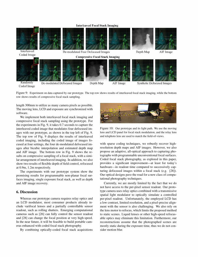
Figure 9: Experiment on data captured by our prototype. The top row shows results of interleaved focal stack imaging, while the bottomrow shows results of compressive focal stack sampling.
length 300mm to utilize as many camera pixels as possible.The moving lens, LCD and exposure are synchronized withsoftware.
We implement both interleaved focal stack imaging andcompressive focal stack sampling using the prototype. Forthe experiments in Fig. 9, it takes 0.7 seconds to capture theinterleaved coded image that modulates four defocused im-ages with our prototype, as shown in the top left of Fig. 9.The top row of Fig. 9 displays the results of interleavedcoded imaging, including the coded image of images fo-cused at four settings, the four de-modulated defocused im-ages after bicubic interpolation and estimated depth mapand AIF image. The bottom row in Fig. 9 shows the re-sults on compressive sampling of a focal stack, with a simi-lar arrangement of interleaved imaging. In addition, we alsoshow two results of flexible depth of field control, refocusedat 0.9m, 1.2m respectively.
The experiments with our prototype system show thepromising results for programmable non-planar focal sur-faces imaging, single exposure focal stack, as well as depthand AIF image recovery.
6. Discussion
Whereas our prototype camera requires relay optics andan LCD modulator, most consumer products already in-clude varifocal lenses and a partially controllable sensorreadout, such as rolling shutters. Emerging computationalcameras such as [26] can fully control the sensor readoutand [28] can change the focal position at very high-speed.In the near future, it will be feasible to build portable cam-eras enhanced with coded focal stack photography.
By combining optically-coded focal stack acquisitions
Figure 10: Our prototype and its light path. We use the movinglens and LCD panel for focal stack modulation, and the relay lensand telephoto lens are used to match the field-of-views.
with sparse coding techniques, we robustly recover high-resolution depth maps and AIF images. However, we alsopropose an adaptive, all-optical approach to capturing pho-tographs with programmable unconventional focal surfaces.Coded focal stack photography, as explored in this paper,provides a significant improvement—at least for today’shardware—in readout time compared to successively cap-turing defocused images within a focal stack (e.g. [28]).Our optical designs pave the road for a new class of compu-tational photography techniques.
Currently, we are mostly limited by the fact that we donot have access to the per-pixel sensor readout. Our proto-type camera uses relay optics combined with a transmissivespatial light modulator to optically simulate a controlledper-pixel readout. Unfortunately, the employed LCD hasa low contrast, limited resolution, and a pixel-precise align-ment with the sensor is also challenging. We also rely onthe lens motor to refocus, which limits the proposed methodto static scenes. Liquid lenses or other high-speed refocus-able optics may eliminate this limitation. Furthermore, ourreconstructions assume that the photographed scenes aremostly static during the exposure time, thus we do not con-sider motion blur.
7. Conclusion and Future WorkIn summary, we introduce coded focal stack photog-
raphy and demonstrate various applications such as pro-grammable unconventional focal surfaces, interleaved focalstack acquisition, and compressive focal stack imaging forrecovering full-resolution AIF images and depths.
In the future, we would like to extend our computationalcamera design to dynamic scenes that include object andcamera motion. We believe that the key challenge for this isthe exploration of advanced sparse focal stack representa-tions that take their dynamic nature into account. Our pro-grammable non-planar focal surface design has the poten-tial to correct the distortion of the employed lenses. Obtain-ing programmable non-planar focal surface projectors andprogrammable non-planar sensor surface cameras withoutmoving parts are the other two interesting avenues of futurework. Finally, we would like to combine more sophisticatedfocal sweeping motions with new kinds of optical codes.
8. AcknowledgementWe thank the reviewers for their feedback. We thank
Matthew O’Toole, Yosuke Bando and Matthew Hirschfor insightful discussion. Gordon Wetzstein was sup-ported by the DARPA SCENICC program and an NSERCPDF. Ramesh Raskar was supported by an Alfred P.Sloan Research Fellowship and a DARPA Young Fac-ulty Award. Tsinghua University affliated coauthors weresupported by the China National Basic Research Project(No. 2010CB731800) and the Key Project of NSFC (No.61120106003, 61035002, 61171119 and U0935001).
References[1] http://vision.middlebury.edu/stereo/data/.[2] E. H. Adelson and J. Y. A. Wang. Single lens stereo with
plenoptic camera. In IEEE Trans. PAMI, 14(2):99–106,1992.
[3] Y. Bando, B.-Y. Chen, and T. Nishita. Extracting depth andmatte using a color-filtered aperture. In ACM SIGGRAPHAsia, 2008.
[4] O. Cossairt and S. Nayar. Spectral focal sweep: Extendeddepth of field from chromatic aberrations. In ICCP, 2010.
[5] O. Cossairt, C. Zhou, and S. Nayar. Diffusion coded pho-tography for extended depth of field. In ACM SIGGRAPH,2010.
[6] P. Favaro. Recovering thin structures via nonlocal-meansregularization with application to depth from defocus. InCVPR, 2010.
[7] P. Favaro and S. Soatto. 3D shape reconstruction and imagerestoration: exploiting defocus and motion blur. SpringerVerlag, 2006.
[8] J. Gu, Y. Hitomi, T. Mitsunaga, and S. Nayar. Codedrolling shutter photography: Flexible space-time sampling.In ICCP, 2010.
[9] M. Gupta, A. Agrawal, A. Veeraraghavan, and S. G.Narasimhan. Flexible voxels for motion-aware videography.In ECCV, 2010.
[10] S. W. Hasinoff and K. N. Kutulakos. Confocal stereo. InIJCV, 81(1):82–104, 2009.
[11] S. W. Hasinoff and K. N. Kutulakos. Light-efficient photog-raphy. In IEEE Trans. PAMI, 33(11):2203–2214, 2011.
[12] Y. Hitomi, J. Gu, M. Gupta, T. Mitsunaga, and S. K. Na-yar. Video from a single coded exposure photograph using alearned over-complete dictionary. In ICCV, pages 287–294,2011.
[13] J. Holloway, A. C. Sankaranarayanan, A. Veeraraghavan,and S. Tambe. Flutter shutter video camera for compressivesensing of videos. In ICCP, 2012.
[14] S. Kuthirummal, H. Nagahara, C. Zhou, and S. K. Nayar.Flexible depth of field photography. In IEEE Trans. PAMI,33(1):58–71, 2011.
[15] A. Levin, R. Fergus, F. Durand, and W. T. Freeman. Imageand depth from a conventional camera with a coded aperture.In ACM SIGGRAPH, 2007.
[16] A. Levin, S. W. Hasinoff, P. Green, F. Durand, and W. T.Freeman. 4D frequency analysis of computational camerasfor depth of field extension. In ACM SIGGRAPH, 2009.
[17] M. Levoy, R. Ng, A. Adams, M. Footer, and M. Horowitz.Light field microscopy. In ACM SIGGRAPH, 2006.
[18] C.-K. Liang, T.-H. Lin, B.-Y. Wong, C. Liu, and H. H. Chen.Programmable aperture photography: Multiplexed light fieldacquisition. In ACM SIGGRAPH, 2008.
[19] V. P. Namboodiri and S. Chaudhuri. Recovery of relativedepth from a single observation using an uncalibrated (real-aperture) camera. In CVPR, 2008.
[20] S. K. Nayar, V. Branzoi, and T. E. Boult. Programmableimaging: Towards a flexible camera. In IJCV, 70:7–22, 2006.
[21] S. K. Nayar and Y. Nakagawa. Shape from focus. In IEEETrans. PAMI, 16(8):824–831, 1994.
[22] R. Ng. Fourier slice photography. In ACM SIGGRAPH,2005.
[23] D. Reddy, A. Veeraraghavan, and R. Chellappa. P2C2: Pro-grammable pixel compressive camera for high speed imag-ing. In CVPR, pages 329–336, 2011.
[24] A. C. Sankaranarayanan, C. Studer, and R. G. Baraniuk. Cs-muvi: Video compressive sensing for spatial-multiplexingcameras. In ICCP, 2012.
[25] A. Veeraraghavan, R. Raskar, A. Agrawal, A. Mohan, andJ. Tumblin. Dappled photography: mask enhanced camerasfor heterodyned light fields and coded aperture refocusing.In ACM SIGGRAPH, 2007.
[26] G. Wan, M. Horowitz, and M. Levoy. Applications of multi-bucket sensors to computational photography. Stanford Com-puter Graphics Laboratory Technical Report, 2012.
[27] J. Yang and Y. Zhang. Alternating direction algorithms forL1-problems in compressive sensing. In SIAM Journal onScientific Computing, 33:250–278, 2011.
[28] C. Zhou, D. Miau, and S. K. Nayar. Focal sweep camerafor space-time refocusing. Technical Report, Department ofComputer Science, Columbia University, 2012.


![FOCAL POINT - CargillAg · tact your Cargill rep to reprice and lock in your Final Focal Point Price. Final Focal Point Price] - [Initial Focal Point Price] = [Focal Point Price Adjustment]](https://static.fdocuments.in/doc/165x107/5ea5a76ffc2e8d744054ad3b/focal-point-cargillag-tact-your-cargill-rep-to-reprice-and-lock-in-your-final.jpg)


![Focal Stack Photography: High-Performance Photography … › ~kyros › pubs › 09.mva.focal.pdfturing and merging a large focal stack [23, 21, 6]. Focal stacks are also a rich source](https://static.fdocuments.in/doc/165x107/5f1eb5a1ac9550333b1aa3c0/focal-stack-photography-high-performance-photography-a-kyros-a-pubs-a-09mvafocalpdf.jpg)


![Light Field Reconstruction from Focal Stack based on Depth ...stanford.edu/class/ee367/Winter2018/sawasdee_ee367_win18_poste… · [1] Mousnier, A & Vural, E & Guillemot, Christine.](https://static.fdocuments.in/doc/165x107/60b13a793da1af440728395b/light-field-reconstruction-from-focal-stack-based-on-depth-1-mousnier-a-.jpg)