
Codebook Based Multi-User MIMO for 5G
50
Codebook Based Multi-User MIMO for 5G MASTER’S THESIS FACULTY OF ENGINEERING | LTH | LUND UNIVERSITY
Transcript of Codebook Based Multi-User MIMO for 5G

Codebook Based Multi-User
MIMO for 5G
MASTER’S THESIS
FACULTY OF ENGINEERING | LTH | LUND UNIVERSITY

Codebook Based Multi-User
MIMO for 5G
Ralf Hajjar and Rahul Venkatraman
[email protected], [email protected]
Department of Electrical and Information Technology
Faculty of Engineering, LTH, Lund University
SE-221 00 Lund, Sweden
Supervisors: Michael Lentmaier (EIT),
Juan Vidal Alegria (EIT),
Harish Venkatraman Bhat (Ericsson)
Examiner: Fredrik Rusek
June 17, 2019

© 2019
Printed in Sweden
Tryckeriet i E-huset, Lund

i
Abstract
Better signal strength is required to provide a good signal service to the UE. For this, different
methods and techniques are available, one of them is codebook type II precoding. This method has a
potential to provide an amount of energy to the user in the required direction more precisely than
Codebook type I. Therefore this method will be put to the test, for a given SNR range, by comparing
the quality of the beamformed signal to non-beamformed signal.
Additional studies have been made about the different characteristics of the channel with simple
changes in the base station with a different antenna configuration exploiting MIMO case. This will lead
to have a large array gain and also spectral efficiency is increased in spatial domain. All these
characteristics are applied for multi-layers and multi-users. For a better understanding of the topic and
for proof of concept, it is being restricted to a single user and a single layer.

ii

iii
Popular Science Summary
Technology has evolved in a small span of time where it has got a revolutionary change in the
telecommunication and mobile phone industry. For example, earlier, we have seen that the mobile
phones are being used for basic calling and messaging. After that, it has been moving towards different
applications which are being added and goes on to support a lot of applications that were not supported
before.
With an increase in the facilities in the new phones era, the demand of more application oriented
in the mobile phone is craving for the better signal requirements and the good service quality.
To match up the requirements and to satisfy the customers or users demands, a change need to
be made to the services and to provide a higher and faster data rates.
The demands and requirements of the user are getting accomplished with a new technology
which is 5G NR. It is codebook based. It has been implemented in LTE and LTE-A using codebook
type I precoding but, major changes have been made so its directionality is more accurate leading to a
better experience to the end user. A new method is being proposed, codebook type II which is in
developing stages. So in this method it is being promised with much greater benefits.

iv

v
Acronym
3GPP 3rd Generation Partnership Project
AP Antenna Port
AWGN Additive White Gaussian Noise
BER Bit Error Rate
CDF Cumulative Distribution Function
CSI Channel State Information
DFT Discrete Fourier Transform
GUI Graphical User Interface
LSB Least Significant Bit
LTE Long-Term Evolution
MIMO Multiple Input Multiple Output
MSB Most Significant Bit
MU-MIMO Multiple Users – Multiple Input Multiple Output
NR New Radio
PA Physical Antenna
PDF Probability Density Function
PMI Precoding Matrix
RI Rank Indicator
RSS Reference Signal Sequences
Rx Receiver
SNR Signal to Noise Ratio
Tx Transmitter
UE User Equipment
W Weight

vi

vii
Acknowledgments
We would like to express gratitude to our supervisor Harish Venkatraman Bhat, Senior
Specialist Beamforming Control at Ericsson AB, Lund. He has provided all the help and
insights needed to accomplish the thesis successfully. We would also like to thank Michael
Lentmaier, Program Director at Lund University for his support and continuous feedback in
order to improve and enhance the work that we have done leading to a proper master thesis
project and report.

viii

ix
Table of contents
1 Introduction 1 1.1 Background ......................................................................................... 1 1.2 Evolution of Codebook ................................................................... 1 1.3 Project Specification ........................................................................... 1 1.4 Thesis Organization ............................................................................ 2
2 Codebook based precoding 3 2.1 MIMO Channel ................................................................................... 3 2.2 Codebook Type I in LTE .................................................................... 4 2.3 Codebook Type II in NR..................................................................... 7
3 Proposed architecture 11 3.1 Graphical User Interface ..................................................................... 12 3.2 Base Station ........................................................................................ 13
4 Approach and implementation 15
4.1 General Methodology and Approach............................................. 15
4.2 Functional set up of Upper Algorithm........................................ 15
4.3 Exploring the MIMO Case .................................................................. 16
4.4 Different Channel Implementation....................................................... 17
5 Results 21 5.1 Single Antenna Transmission ................................................................ 21
5.1.1 QPSK Modulation ................................................................. 21 5.1.2 8-PSk Modulation ................................................................. 24 5.2 2x2 MIMO Transmission .................................................................... 25 5.3 4x4 MIMO Transmission .................................................................... 26 5.4 Rayleigh Channel ................................................................................ 27
6 Conclusion 29
7 Future Work 31
8 References 33

x

xi
List of figures
2.1 MIMO Channel .......................................................................... 3
2.2 Oversampling factors and antenna port layout ........................... 8
3.1 System model design ................................................................. 11
3.2 User equipment parameters using graphical user interface ....... 12
3.3 Beamforming for multiple UEs ................................................. 13
3.4 Antenna port mapping ............................................................... 14
3.5 Antenna mapping ...................................................................... 14
4.1 Digital signal representation ...................................................... 17
4.2 Properties of a Gaussian channel............................................... 18
4.3 PDF & CDF ............................................................................... 19
5.1 QPSK signal constellation with perfect CSI ......................... 21
5.2 QSK signal constellation with medium CSI ......................... 22
5.3 QPSK signal constellation with poor CSI ................................. 23
5.4 8-PSK signal constellation with perfect CSI ............................. 24
5.5 BER vs SNR for a 2x2 MIMO transmission ............................. 25
5.6 BER vs SNR for a 4x4 MIMO transmission ............................. 26
5.7 BER vs Snr for a 4x4 MIMO transmission
with Rayleigh channel ............................................................... 27

xii

xiii
List of Tables
2.1 Codebook for 1-layer and 2-layer CSI reporting ........................... 4
2.2 Bit mapping to 1-layer and 2-layer.............................................. 5
2.3 Supported configurations of (N1,N2) and (O1,O2) ....................... 5
2.4 Supported configurations of (Ng,N1,N2) and (O1,O2) .................. 6
2.5 Codebook Type II for 1-layer and 2-layer CSI reporting ............ 7
2.6 Sub-band indices mapping .......................................................... 8
2.7 Wideband indices mapping ......................................................... 9
2.8 Combinatorial coefficient ............................................................ 9


1
Chapter 1: Introduction
This chapter introduces the thesis, the purpose why it is being carried out, goals and the complexities involved.
Also, this chapter provides a background of the thesis and what could be done in future work.
1.1 Background
The thesis was carried out and supervised in cooperation with Ericsson AB. The thesis
describes a detailed study and analysis of codebook based precoding for 5G. Then the thesis
covers a simulation model where codebook type II precoding was implemented. Later, the
thesis explores the possibilities of using codebook type II precoding for multi user MIMO and
the complexities involved with it. Finally, an analysis of the simulation results for different
channel conditions is made and the results and future work are discussed.
1.2 Evolution of Codebook
CSI, better known as Channel State Information, describes how a signal going from the
transmitter to the receiver is getting affected by scattering factors, power decay due to distance
and fading [1].
Codebook based transmission was introduced when MIMO was implemented in LTE and
LTE-Advanced since the actual benefits of MIMO would rely on the accurate channel
knowledge at the transmitter. Hence the importance of codebook implementation. 3GPP
introduced two types of codebook. In 3gpp LTE, codebook type-I was introduced and in 3GPP
NR, codebook type II was introduced. Both codebooks were based on 2D DFT beams and
provide CSI feedback for beam selection [1], however, codebook type II was introduced since
it was believed that a more accurate CSI feedback was needed and the reason for that was
codebook type II would report both wideband and sub-band indices for a more accurate CSI
feedback, meaning a better MIMO transmission for NR [2] [3]. Hence the purpose of this
project where we study and analyze codebook type II for 5G and how that would benefit multi-
user MIMO in the future and the complexities involved in implementing it.
1.3 Project Specification
The main aim of the thesis is to study and implement codebook type II for NR systems.
To implement this, the use of CSI is quite important in understanding the state of the channel
in the downlink so the UE is required to send back a feedback in the uplink about the channel.
Therefore, to successfully apply codebook type II, the following parts are required:
Understanding the concepts behind the codebook, how it is defined in the specifications
by the 3GPP and attempt to apply it for a single antenna at the UE and a single antenna
at the base station and gradually go into 2x2 MIMO then later 4x4 MIMO and establish
its benefit.
Comparing the BER between data transmitted without codebook and data transmitted
with codebook for different antenna port layout and oversampling factors and conclude
if it is beneficial to use the codebook or not.

2
2 Introduction
Simulating the system model in different channel conditions and characteristics leading
to a better understanding of the ideal conditions where the system could be implemented
in the future
1.4 Thesis organization
The rest of the thesis is organized in the following manner:
Chapter 2 is more focused on the theory side. The first section of this chapter mainly
discusses about codebook type I in LTE, the different configurations supported, and the
required parameters for implementation. The second section of this chapter discusses about
codebook type II in NR, the main function on which the codebook is based on and the
explanation of the required parameters.
Chapter 3 describes the system model design going through each block and explains the
importance of that block in the overall procedure.
Chapter 4 defines the implementation and approach that were used going from general
approach, to exploring MIMO case and later considering channel characteristics.
Chapter 5 includes all the results for different scenarios where codebook type II was
implemented successfully. Signal constellations and plotting of BER vs SNR are included
in this chapter which are analysed later.
Chapter 6 concludes the reports with a quick summary of all the chapters. Final remarks
and potential future work are also briefly discussed in this chapter.

3
Chapter 2: Codebook based precoding
This chapter introduces the two types of codebooks defined for LTE and NR respectively, and defines the
parameters required for each codebook.
Codebook based precoding is a promising new technique of beamforming. Precoding
means multiple data streams or a single data stream are transmitted from the transmit antennas
with independent and appropriate weightings that will lead to maximize the throughput at the
receiver side. Codebook precoding was introduced in LTE where predefined matrices were
calculated and assigned to the transmitting antennas over the channel. However, precoding has
evolved where codebook type II was introduced in NR.
Codebook type II relies on the UE reporting back to the base station with indices that will
be used in order to calculate the appropriate weights more precisely for each antenna as will be
explained further in this chapter.
2.1 MIMO Channel
The MIMO channel is the medium that the transmitter and the receiver use to establish a
connection between them. In what follows, up to 4 antennas at the Tx and 4 antennas at the Rx
are considered, i.e. 4x4 MIMO system.
The following figure illustrates a 4x4 MIMO system having H as the channel matrix and
adding noise (Gaussian or Rayleigh).
Figure 2.1: MIMO channel representation
A channel is referred as physical transmission medium which is used as a barrier to send
a message or an information between one or multiple senders and one or multiple receivers. In
communications, the signals are being transmitted from transmitter to receiver. In between the
transmitter and receiver, there needs to be a medium to transmit which can be either guided
wireless medium or wired medium. In this context, we are using a wireless medium to transmit
the signal. [4]

4
4 Codebook based precoding
The output y at the receiver follows the following equation:
𝑦 = 𝐻𝑊𝑥 + 𝑛
Where H is the identity matrix, x is the transmitted message, noise n is assumed to be
Gaussian in most the project and later on changed to Rayleigh noise in order to simulate
different channels behavior, and the precoding matrix W which is described in depth in the
following sections of this chapter.
2.2 Codebook Type I in LTE
In order to understand codebook type I, we should know about CSI at the UE side. The
CSI always recommends a proper pre-coding matrix for a better signal in the channel. The set
of all pre-coding matrices forms the codebook. To assign it in an efficient manner, codebook
type I is used in LTE and LTE-A. There are two different configurations supported:
1) Codebook type I single panel:
In type I codebook single panel, the UE is configured with higher layer parameter and the
codebook type is set to type I. Each PMI (Precoding Matrix index) corresponds to a codebook
index which is shown in table 2.1. So bit map parameter forms a bit sequence from a5, a4..a1,a0,
where a0 is the LSB and a5 is the MSB. For layer 1 the bits a0 to a3 are associated with codebook
indices 0 to 3, for layer 2 bits a4 and a5 are associated with codebook indices 0 and 1 as seen in
table 2.2.
Table 2.1: Codebook for 1-layer and 2-layer CSI reporting [2]
Codebook index Number of layers
1 2
0 1
√2 [
11
] 1
2 [
1 11 −1
]
1 1
√2 [
1j]
1
2 [
1 1𝑗 −𝑗
]
2 1
√2 [
1−1
] _
3 1
√2[
1−j
] _

5
Codebook based precoding 5
Table 2.2: Bit mapping to layer 1 and layer 2 [2]
Codebook index Number of Layers
1 2
0 a0 _
1 a1 a4
2 a2 a5
3 a3 _
When UE is configured and set to type 1 single panel, the bit map parameter form a sequence
r7 r6 r5 …r0 , where r7 is the MSB and r0 is the LSB, the following supported configurations (N1
N2) and their corresponding oversampling factors (o1,o2) .
Table 2.3: Supported configurations of (N1,N2) and (O1,O2) [2]
Number of CSI-RS ports (N1,N2) (O1,O2)
4 (2,1) (4,-)
8 (2,2) (4,4)
(4,1) (4,-)
12 (3,2) (4,4)
(6,1) (4,-)
16 (4,2) (4,4)
(8,1) (4,-)
24 (6,2)(4,3) (4,4)
(12,1) (4,-)
32 (8,2)(4,4) (4,4)
(16,1) (4,-)

6
6 Codebook based precoding
Max rank indicator is the same as the number of antennas on each side if the number is
the same, i.e. for a 4x4 MIMO, the maximum achievable rank is 4. If the number of antennas
at the receiver is different than the number of antennas at the transmitter, the maximum
achievable rank indicator is the one with less number of antennas, i.e. for a 2x1 MIMO, the
maximum achievable rank is 1.
Type I single panel support up to rank 8 which is associated with the number of layers
per Panel. For Rank 1 and 2, the number of supported beams ranges from 1 to 4 while for higher
ranks, the number of beams supported is 1.
For Ranks≥ 2, the PMI codebook assumes the precoder structure as
𝑊 = 𝑊1 × 𝑊2 [3]
where 𝑊1 = [𝐵 00 𝐵
] having B the oversampled 2D DFT beams and 𝑊2 represents the beam
selection and QPSK co-phasing between two polarizations.
2) Codebook Type I Multi-Panel:
There are a lot of similarities between the two supported codebook type I. However,
codebook type I has introduced inter-panel co-phasing denoted by 𝑝 = 0,1, … , 𝑁𝑔 − 1 where
𝑁𝑔 is the number of panels. Inter-panel co-phasing shapes the radiation pattern for panels
redirecting its energy in a more specific direction. The supported number of panels is either
𝑁𝑔 = 2 or 𝑁𝑔 = 4.
The following table represents the antenna port layout and its corresponding oversampling
factors that are supported for multi-panel:
Table 2.4: Supported configurations of (𝑵𝒈, 𝑵𝟏, 𝑵𝟐) and (𝑶𝟏, 𝑶𝟐) [2]
Number of CSI-RS ports (𝑁𝑔, 𝑁1, 𝑁2) (𝑂1, 𝑂2)
8 (2,2,1) (4, −)
16
(2,2,2) (4,4)
(2,4,1), (4,2,1) (4, −)
32
(2,4,2), (4,2,2) (4,4)
(2,8,1), (4,4,1) (4, −)

7
Codebook based precoding 7
Inter-panel co-phasing denoted by 𝑝 is configurable according to 2 modes:
Mode 1: Wideband inter-panel co-phasing with payload = 2bits/subband having 𝑁𝑔 = 2 or
𝑁𝑔 = 4.
Mode 2: Subband inter-panel co-phasing with payload = 4bits/subband having 𝑁𝑔 = 2.
2.3 Codebook type II in NR
As previously mentioned, Codebook type II was designed to have a better CSI feedback
than Codebook type I since a more accurate CSI feedback was needed. Codebook type I had
predefined matrices based on the number of layers and CSI-RS ports. The concept of weight
beamforming still stands in codebook type II. However, the weight W is no longer
predefined. It is based on the UE feedback providing important indices that forms W in
codebook type II as seen in the table below. The base station uses these indices creating the
new codebook as seen in the table below:
Table 2.5: Codebook Type II for 1-layer and 2-layer CSI reporting [2]
Main parameters that constitute codebook type II:
𝜀: Number of layers. The number of layers currently supported is up to 2 layers
However additional studies are in progress to support up to 4 layers.
𝑞1,𝑞2: Rotation factors where
o 𝑞1 𝜖 {0,1, … , 𝑂1 − 1} and 𝑞2 𝜖 {0,1, … , 𝑂2 − 1}
L: Number of beams per layer. 𝐿 = 2 for CSI-RS ports = 4 and 𝐿 ∈ {2,3,4} for
CSI- RS ports > 4
Layers
𝜀 = 1 𝑊𝑞1,𝑞2,𝑛1,𝑛2,𝑝1
(1),𝑝1
(2),𝑖2,1,1
(1)
𝜀 = 2 𝑊
𝑞1,𝑞2,𝑛1,𝑛2,𝑝1(1)
,𝑝1(2)
,𝑖2,1,1,𝑝2(1)
,𝑝2(2)
,𝑖2,1,2
(2)=
1
√2 [𝑊
𝑞1,𝑞2,𝑛1,𝑛2,𝑝1(1)
,𝑝1(2)
,𝑖2,1,1
(1)𝑊
𝑞1,𝑞2,𝑛1,𝑛2,𝑝2(1)
,𝑝2(2)
,𝑖2,1,2
(2)]
Where 𝑊𝑞1,𝑞2,𝑛1,𝑛2,𝑝1
(1),𝑝1
(2),𝑐𝑙
(1)=
1
√𝑁1𝑁2 ∑ (𝑝𝑙,𝑖(1)
𝑝𝑙,𝑖(2)
)22𝐿−1𝑖=0
[∑ 𝜇
𝑚1(𝑖)
,𝑚2(𝑖)𝑝𝑙,𝑖
(1)𝑝𝑙,𝑖
(2)𝜑𝑙,𝑖
𝐿−1𝑖=0
∑ 𝜇𝑚1
(𝑖),𝑚2
(𝑖)𝑝𝑙,𝑖+𝐿(1)
𝑝𝑙,𝑖+𝐿(2)
𝜑𝑙,𝑖+𝐿𝐿−1𝑖=0
] , 𝑙 = 1,2

8
8 Codebook based precoding
𝑂1, 𝑂2 ∶ Oversampling Factors
Figure 2.2: Antenna port layout and oversampling factor
Oversampling is the process of sampling a signal at rate much higher than the Nyquist
rate. As seen in table 2.3, the two supported configurations of (𝑂1, 𝑂2) are either (4, -) or (4,
4). Having a 1-D antenna port layout with a (4, -) oversampling factor means that you the
signal is oversampled 4 times horizontally. And having a 2-D antenna port layout with a (4,
4) oversampling factor means that the signal is oversampled both horizontally and vertically
4 times as seen in figure 2.2.
Other significant parameters are:
𝑝𝑙,𝑖(2)
: Sub-band amplitude value set mapping (1 bit) as seen in table 2.6
𝑝𝑙,𝑖(1)
: Wideband amplitude value set mapping (3 bits) as seen in table 2.7
𝑛1, 𝑛2 ∶ Parameters indicating the i-th beam in the selected orthogonal basis set where
o 𝑛1 = [𝑛1(0)
, … , 𝑛1(𝐿−1)
] and 𝑛1(𝑖)
𝜖 {0,1, … , 𝑁1 − 1}
o 𝑛2 = [𝑛2(0)
, … , 𝑛2(𝐿−1)
] and 𝑛2(𝑖)
𝜖 {0,1, … , 𝑁2 − 1}
Table 2.6: Sub-band indices mapping [2]
𝑘𝑙,𝑖(2)
𝑝𝑙,𝑖(2)
0 √12⁄
1 1

9
Codebook based precoding 9
Table 2.7: Wideband indices mapping [2]
𝑘𝑙,𝑖(1)
𝑝𝑙,𝑖(1)
0 0
1 √164⁄
2 √132⁄
3 √116⁄
4 √18⁄
5 √14⁄
6 √12⁄
7 1
𝜑𝑙,𝑖 = 𝑒𝑗2𝜋𝑐𝑙,𝑖
𝑁𝑃𝑆𝐾⁄
indicating that sub-band amplitude = ‘false’, dependent on the
combinatorial coefficient and the number of constellation points
𝜇𝑙,𝑚 = [𝑢𝑚 𝑒𝑗
2𝜋𝑙
𝑂1𝑁1𝑢𝑚 ⋯ 𝑒
𝑗2𝜋𝑙(𝑁1−1)
𝑂1𝑁1 𝑢𝑚]
𝑇
; 𝑢𝑚 = 1 for 1-D antenna port layout
𝐶(𝑥, 𝑦): Combinatorial coefficient where 𝑥 = 𝑁1𝑁2 − 1 − 𝑛(𝑖) and 𝑦 = 𝐿 − 𝑖 for 𝑖 = 0, … , 𝐿 − 1.
These combinatorial coefficient are pre-calculated for any (x, y) combination as seen
in table 2.8 below.
Table 2.8: Combinatorial coefficient [2]
x y 1 2 3 4
0 0 0 0 0
1 1 0 0 0
2 2 1 0 0
3 3 3 1 0
4 4 6 4 1
5 5 10 10 5
6 6 15 20 15
7 7 21 35 35

10
10 Codebook based precoding

11
Chapter 3: Proposed architecture
In the previous chapter, we have explained what the contents of codebook type I and codebook type II are. We
would like now to carry out an implementation of codebook type II in multiple scenarios and understand what
improvements we can get compared to non-codebook transmissions.
The following block diagram represents the model design that was used:
Figure 3.1: Model system design
This block diagram in itself is not state-of-the-art. It is very similar to what was
implemented in codebook type I. However, what we did is to adjust it appropriately to support
codebook type II. The major modifications are the UE feedback, the weights calculation and
beamforming. As previously explained, codebook type I had predefined matrices. According
to the codebook index, Weight W was selected then multiplied by the data needed to be
transmitted and sent over the channel to be decoded by the receiver. This method indicated that
the UE was in a certain sector without identifying the exact position of the UE. What we tried
to do is to benefit from the UE feedback to determine important indices as mentioned in the
previous chapter, calculating W accordingly and then simulating for different MIMO
cases and channel conditions.

12
12 Proposed architecture
3.1 Graphical User interface
The graphical user interface was created to simulate the UE reporting the previously
mentioned parameters using Matlab. The options that the user can select from are limited to
what is currently supported by the codebook:
Antenna port layout according to table 2.3
Oversampling factors according to table 2.3
Sub-band indices according to table 2.6
Wideband indices according to table 2.7
M-PSK: Either 4-PSK or 8-PSK
The number of wideband and sub-band indices are dependent on the antenna port layout
chosen. Therefore, the number of slots available in the GUI will adjust accordingly.
Also, any wrong entry of the data will prompt an error and will lead the GUI to fail in sending
the parameters.
The figure representing the graphical user interface is shown below:
Figure 3.2: User equipment parameters using graphical user interface

13
Proposed architecture 13
3.2 Base Station
The base station is considered to be the major part of the model design. It consists of
multiple blocks as mentioned below:
Data Generator: Generating 106 random bits forming the data desired to be transmitted
to the UE.
M-PSK: Based on the user decision (Either Q-PSK or 8-PSK) using the GUI, the data
transmitted will be modulated accordingly. No other modulation scheme is supported.
Weight Calculation: Weight calculation is the basis of codebook type II. It is based on
the function defined in table 2.5. It depends on the number of layers, wideband indices,
sub-band indices, combinatorial coefficient, number of antenna ports, antenna port
layout and oversampling factors. Having multiple antennas means multiple weights.
For simplicity purposes, the weight for two antenna or four antennas were assumed to
be orthogonal.
Beamforming: Beamforming is a technique used in constructing antenna radiation
pattern. The reason for using beamforming is that the beam is directed to the UE leading
to less energy being wasted.
Figure 3.3: Beamforming for multiple UEs
There are different techniques to implement beamforming. One of the most familiar
ones is beamforming by precoding where the radiation form is changed by applying a
precoding matrix [6]. However, in NR specification, precoding stage is only supported
for uplink and not for downlink.
Antenna port mapping: Antenna ports are considered to be logical entities rather than
physical. These ports are distinguished by their RSS [7]. The number of ports defined
in codebook Type II, 𝑃𝐶𝑆𝐼−𝑅𝑆, is dependent on the antenna port layout chosen, meaning
that for a supported configuration of (𝑁1, 𝑁2), 𝑃𝐶𝑆𝐼−𝑅𝑆 = 2𝑁1𝑁2, i.e. Having (𝑁1, 𝑁2) =(2,1) supported in table 1, 𝑃𝐶𝑆𝐼−𝑅𝑆 = 4. It is up to the base station how these ports are
assigned to the physical antennas. The UE is not aware how the mapping has been
carried out by the base station rather the UE should handle this during demodulation.

14
Figure 3.4: Antenna port mapping
Antenna mapping: Antenna mapping is the process that enables one or multiple users
to transmit their data on different antenna ports. It is dependent on the Rank Indicator
(RI) and the Weight (W) recommended by the UE based on previous calculations as
seen in the block diagram below:
Figure 3.5: Antenna mapping

15
Chapter 4: Approach and implementation
4.1 General approach and methodology:
This chapter discusses the approach and implementation of the block design that was
discussed in chapter 3 with a fully-fledged functionality.
General steps followed in implementing the codebook type II:
The first step is the setup of the GUI which is shown in the previous section. Through
the GUI, different parameters such as antenna port layout, oversampling factors,
wideband and sub-band indices are chosen. The assumption made here that these
manually chosen parameters represents the UE report to the base station. Therefore, for
simplicity purposes, an approximation was made on UE Report stating that UE has
chosen these parameters and forward theses parameters to the codebook.
After GUI selection, the main function for a single layer codebook type II was defined
where the required parameters were explained in the second chapter.
Once the weight is calculated, the modulated signal is multiplied with the weights and
transmitted to UE.
In order to check the effect of codebook on the transmitted signal, a comparison
between the beamformed signal and non-beamformed signal will take place for a single
antenna given a certain noise power.
While transmitting it in the channel, a second assumption made is that the channel is
static.
A BER calculation is made for a single antenna with given noise power.
Once satisfied with the results, multiple antennas transmission between the UE and the
base station were implemented for a given SNR range.
4.2 Functional set up of upper algorithm:
The setup starts by generating a QPSK signal with different wideband, sub-band indices
that will lead to a better understanding of how these reported indices can affect the beamformed
signal. So as to test this case we plot the beamformed QPSK signal with generated QPSK signal
for every possible wideband and sub-band indices to understand which CSI gives us better
signal. In this test AWGN channel is used.
After, the QPSK implementation of noise is added with varying SNR. This would lead to
better understanding of how noise is affecting the signal at every possible stage and counting
BER at every SNR.
To transmit the signal over a channel, an accurate number of users and number of antennas
is required both at the transmitter side and receiver side.

16
16 Approach and implementation
Implementing using one antenna at transmitter and one antenna at user:
In this section, the case of one antenna at the base station and a single user with single
antenna is implemented. After getting the Q-PSK encoded signal, it is sent over a channel that
was described in the previous chapter. Then the BER is calculated by comparing the beam
formed signal with the originally sent data.
4.3 Exploring the MIMO case:
In order to improve the quality of service, and spectral efficiency, MIMO is needed to
achieve better gain, an increase of data rate and reduction of BER.
There are some disadvantages as we increase the number of antennas in both transmitter
and receiver mainly complexity in the structure, the number of RF units will increase, more
power is required. Yet the advantages are more important and significant when compared with
the disadvantages.
After showing the importance of precoding for a single user with a single antenna, 2x2
MIMO was implemented where each antenna had its own weight based on the UE feedback.
The data that was sent by the user was multiplied by its appropriate weight and later decoded
at the receiver side. Then an analysis of the BER vs SNR was done in order to assess its
performance.
The same work was done for 4x4 MIMO transmission. Each antenna had its own weight.
These weights were orthogonal to each other yet they had different wideband and sub-band
indices sent by the UE. A comparison was done after decoding the transmitted message at the
receiver in order to assess the benefits of beamforming for a 4x4 MIMO compared to all
previously mentioned scenarios.

17
Approach and implementation 17
4.4 Different channels implementation:
As in the above task the implementation is done by increasing the number of antennas and
keeping a single channel. In this section, 2 different channels are used to determine the
transmitted signal characteristics in different SNR
4.4.1 Implementing using four antennas and two channels:
Four antennas are used at the transmitter side and the receiver side. The channels that
were chosen to conduct this testing were:
1) Gaussian Channel:
One of the most common channels to use is the Additive White Gaussian Noise Channel.
In real life, noise is much more complex than this model however, it is very efficient when
simulating background noise or amplifier noise. In this section we will have a closer look on
AWGN channels and their properties for different signal to noise ratio (SNR). In a
communication system, data is often represented in a binary form which is discrete so we use
digital to analog converter to accommodate them to analog signals that can be transmitted
through physical channels. Within this channel model, the received signal can be expressed as:
𝑌 = 𝑋(𝑡) + 𝑁(𝑡) [4]
Where 𝑋(𝑡) is the modulated signal which is continuous and 𝑁(𝑡) is the noise which is added
here 𝑁(𝑡) is AWGN Now we look into some properties of Gaussian channel
Figure 4.1: Digital signal representation

18
18 Approach and implementation
Generally it is denoted as 𝑵(0, √𝑁) which means Zero mean and √𝑁 is the variance. A
random variable is said to be Gaussian function if the distribution is having the following
properties shown in the figure 4.2.
Figure 4.2: Properties of a Gaussian channel [5]
The parameters are described below:
𝜇 is the mean of the distribution
σ is the standard deviation
σ2 is the variance
In a communication channel the signaling power is being constrained at the transmitter
𝐸 [𝑋2] ≤ 𝑃
The power constraint is therefore defined to develop a realistic system otherwise we
would choose as many signal alternative as far apart as one likes which means there is no limit
in the information transmission for a single channel use.
In the case of massive MIMO, the channel between each transmitter antenna and receiver
would have individual and independent channels. For simplicity purposes, perfect CSI is
assumed. MIMO will use the true channel matrix without the need of correlations.

19
Approach and implementation 19
2) Rayleigh Channel:
In this section, Rayleigh channel is discussed. It is a channel model where fading follows
a Rayleigh distribution. This type of channel is also called small scale fading. If the signal
underwent multiple reflective paths that are large in number and there is no line of sight
component, then from the statistical data we can say that the signal has undergone Rayleigh
fading.
The probability density formula of Rayleigh distribution is given as:
𝑥
𝜎2𝑒
−𝑥2
2𝜎2⁄[8]
Where x has a Rayleigh distribution with parameter σ
Figure 4.3: PDF & CDF [5]
As σ increases the distribution gets wider and wider.
The above graphs will closely look like Gaussian distribution as the number of elements
in the random variable is increasing. This is explained by the central limit theorem.
Certain characteristics of MIMO transmission needs to be taken care of.
Many incoming waves
Many outgoing waves
Correct antenna spacing
Random incoming waves
Random outgoing waves

20
20 Approach and implementation
These conditions leads to rich scattering occurring at both transmitter and receiver. Channel
knowledge to the transmitter also plays a huge role in this implementation.
In most cases, the channel is unknown to the transmitter therefore the assumption made is
that the channels are orthogonal and uncorrelated.
In the thesis, the entire channel is assumed to be Gaussian and it gives an array gain which
can be shown using the capacity formula which is shown below
𝐶 = ∑ log2(1 +𝐸𝑠
𝑀𝑇𝑁0𝜆𝑖)
𝑘𝐾=1 [8]
For orthogonal case 𝜆1 = 𝜆2 = 𝜆3 … … . . = 𝜆𝑀 = 𝑀
The above formula changes to:
𝐶 = 𝑀log2 (1 +𝐸𝑠
𝑁0) [8]
The expectation from this test is that the beam formed will have a slightly higher bit error rate
but that could be ignored regarding the possible benefits that could be achieved.
Next, an observation of the signal characteristics with different channels was made. These
channels have different characteristics at low SNR and high SNR and according to the theory
we can say Gaussian is far better than Rayleigh which is expected to be shown in the result.
All the above work is being simulated through Matlab.
21
Chapter 5: Results
After discussing in the previous chapters, the theoretical and implementation parts in the
thesis, this chapter focuses on the results obtained from the implementation of codebook type
II for a single user in single and multiple antenna transmission with different channel conditions
between the UE and the base station.
5.1 Single antenna transmission
5.1.1 QPSK modulation
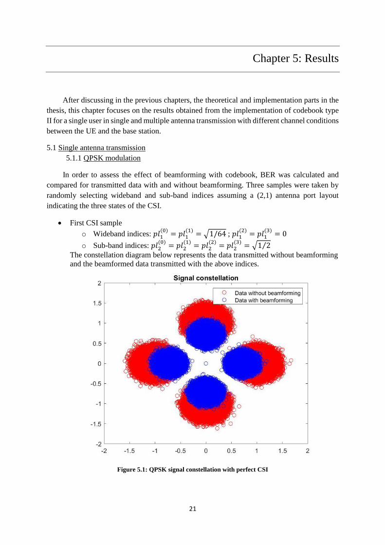
In order to assess the effect of beamforming with codebook, BER was calculated and
compared for transmitted data with and without beamforming. Three samples were taken by
randomly selecting wideband and sub-band indices assuming a (2,1) antenna port layout
indicating the three states of the CSI.
First CSI sample
o Wideband indices: 𝑝𝑙1(0)
= 𝑝𝑙1(1)
= √1/64 ; 𝑝𝑙1(2)
= 𝑝𝑙1(3)
= 0
o Sub-band indices: 𝑝𝑙2(0)
= 𝑝𝑙2(1)
= 𝑝𝑙2(2)
= 𝑝𝑙2(3)
= √1 2⁄
The constellation diagram below represents the data transmitted without beamforming
and the beamformed data transmitted with the above indices.
Figure 5.1: QPSK signal constellation with perfect CSI
22
22 Results
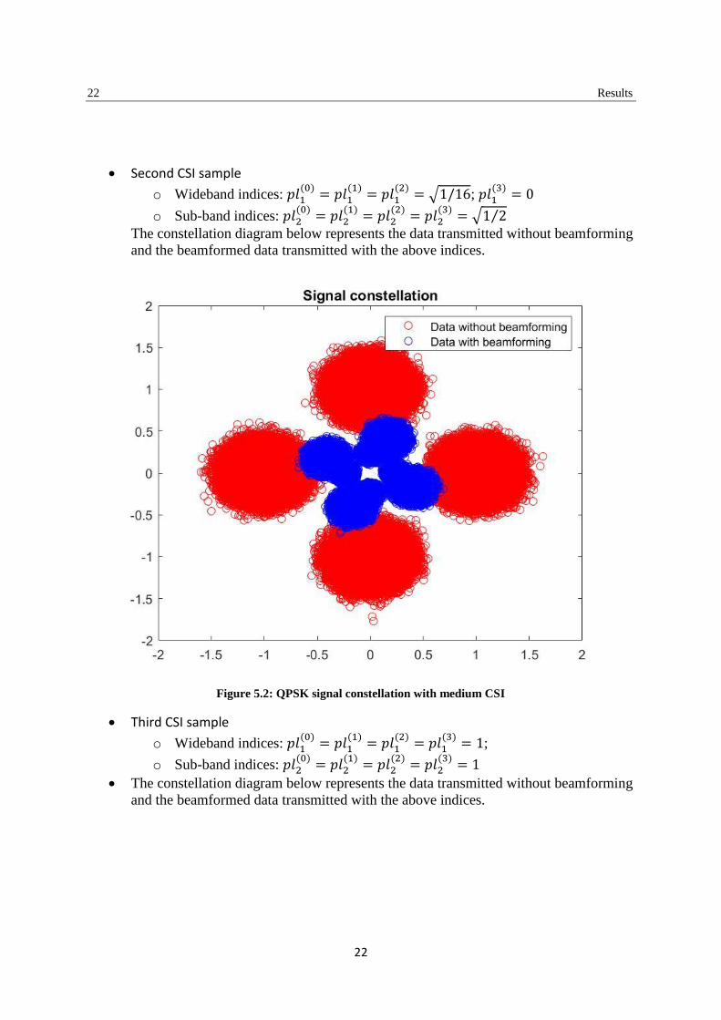
Second CSI sample
o Wideband indices: 𝑝𝑙1(0)
= 𝑝𝑙1(1)
= 𝑝𝑙1(2)
= √1/16; 𝑝𝑙1(3)
= 0
o Sub-band indices: 𝑝𝑙2(0)
= 𝑝𝑙2(1)
= 𝑝𝑙2(2)
= 𝑝𝑙2(3)
= √1 2⁄
The constellation diagram below represents the data transmitted without beamforming
and the beamformed data transmitted with the above indices.
Figure 5.2: QPSK signal constellation with medium CSI
Third CSI sample
o Wideband indices: 𝑝𝑙1(0)
= 𝑝𝑙1(1)
= 𝑝𝑙1(2)
= 𝑝𝑙1(3)
= 1;
o Sub-band indices: 𝑝𝑙2(0)
= 𝑝𝑙2(1)
= 𝑝𝑙2(2)
= 𝑝𝑙2(3)
= 1
The constellation diagram below represents the data transmitted without beamforming
and the beamformed data transmitted with the above indices.

23
Results 23
Figure 5.3: QPSK signal constellation with poor CSI
The three samples of CSI represent the good, the bad and the worst. The first CSI sample
had a BER of 0.01% indicating that the beamformed signal is demodulated perfectly for a given
SNR. The second CSI sample had a BER of 45% indicating that the data received was poorly
demodulated. The third and final CSI sample had a BER of 99% indicating that the receiver
was not capable of decoding the message sent correctly due to the bad CSI report. The reason
for that fluctuation in the results is the wideband indices reported by the UE that are closer to
one. Sub-Band indices do not affect as much in CSI report.

24
24 Results
5.1.2 8-PSK modulation
Similarly, for 8-PSK modulation, the above result is also applicable. Having a perfect CSI with
wideband indices relatively low, the BER is roughly 0.1%.
The constellation diagram below represents the data transmitted without beamforming and the
beamformed data transmitted with the following indices:
o Wideband indices: 𝑝𝑙1(0)
= 𝑝𝑙1(1)
= √1/64 ; 𝑝𝑙1(2)
= 𝑝𝑙1(3)
= 0
o Sub-band indices: 𝑝𝑙2(0)
= 𝑝𝑙2(1)
= 𝑝𝑙2(2)
= 𝑝𝑙2(3)
= √1 2⁄
Figure 5.4: 8-PSK signal constellation with perfect CSI
As we look into these plots, there are no major difference in terms of constellation except
overall amplitude gets smaller through the precoding block. But having a much better CSI
due to the pre-coded signal can compensate for this disadvantage and will reduce the
corrupted effect of the communication channel as shown in the following sections.

25
Results 25
5.2 2x2 MIMO transmission
As mentioned in chapter 4, in order to increase the spectral efficiency, diversity is needed.
Therefore, increasing the number of antennas at the UE and the base station will provide the
necessary gain without too much complexity.
For this part, a plot of the BER vs SNR will pinpoint the gain attained from implementing
codebook type II for 2x2 MIMO transmission vs single user transmission vs non-beamformed
transmission.
These plots were generated using the 𝑄(𝑥) function. The Q-function is the tail distribution
function of the standard normal distribution or in other words, it is the probability that a normal random
variable will obtain a value larger than x standard deviations. This function was used to determine the
BER as follows:
𝑃𝑏 = 𝑄(√𝑥 × 2 × 𝑠𝑛𝑟)
Where x is the ratio of the energy of the beamformed signal to the non-beamformed signal and
snr is the signal to noise ratio in linear format.
Figure 5.5: BER vs SNR for 2x2 MIMO transmission

26
26 Results
So, from above the graph at low SNR, the BER is almost the same since the noise signal
power is dominating. But, at high SNR, signal power is dominating over noise power, meaning
lower BER is expected as the number of antennas is increasing, the gain is also increasing. This
gain can be measured along the x axis at any given value, which is roughly 2dB gain.
5.3 4x4 MIMO transmission
Going into higher number of antennas at the UE and the base station means higher complexity
yet more diversity and gain is achievable. The plot below represents the gain attained from
implementing codebook type II for a 4x4 MIMO transmission compared to previously tested
schemes.
Figure 5.6: BER vs SNR for a 4x4 MIMO transmission
As seen in the figure above, implementing codebook type II for 4x4 MIMO transmission is
achieving a higher diversity and attainable gain than the 2x2 MIMO transmission and single
antenna transmission. Combining the different multipath components has led to a better
scattering, higher data rate and capacity.

27
Results 27
5.4 Rayleigh
Figure 5.7 represents a plot of the BER vs SNR in the case of Rayleigh Channel considering
the different MIMO cases:
Figure 5.7: BER vs SNR for a 4x4 MIMO transmission with a Rayleigh Channel
Differences between Rayleigh and Gaussian channel:
As from above graphs comparing 5.6 and 5.7 the following observations are made. The BER
at a given SNR for a given signal in Gaussian medium has a better BER than the Rayleigh
Medium. According to the central limit theorem, the sum of a set of random variables with any
distribution will converge to the Gaussian distribution. Hence, the Rayleigh distribution will
converge to Gaussian. At low SNR, the BER of the signal is almost close or same whether it is
Gaussian or Rayleigh. But at high SNR there is a noticeable difference between the channels
and also the gain.

28
28 Results

29
Chapter 6: Conclusion
The implementation of Codebook type II in NR systems was covered during this project. The
thesis covered the evolution of Codebook from LTE to NR. The thesis discusses the main
components of Codebook Type II and the parameters involved in making it the basis for NR.
Then the implementation was structured for a different scenario ranging from changing the
number of antennas both at the transmitter and the receiver, getting different UE reports
affecting the codebook, changing the channel conditions and observing its characteristics and
behavior of the transmitted signal.
These studies were a proof of concept since no previous attempt was made in NR, leading the
way to great potentials in implementing the work done for multi-user MIMO achieving high
spectral efficiency, reduction in BER due to advanced signal processing and achieving
extension of cell coverage.

30

31
Chapter 7: Future Work
The main purpose of the thesis was to simulate precoding using codebook type II and explore
using it for multi user MIMO. Hence, the future work should be based on the outcomes of this
thesis and attempt to implement it for multi user MIMO. The main issue with MU-MIMO is
having a perfect CSI. Through the implementation of codebook type II, the CSI has improved
drastically. Hence, implementing MU-MIMO in the future will enable direct gain to be
obtained due to MU-multiplexing. Also, the propagation issues such as antenna correlation and
channel rank loss that affects single user MIMO will not have the same effect on MU-MIMO.
Finally, spatial multiplexing gain could be achieved at the base station without the need for
some expensive antennas at the UE side. All these advantages can be accomplished since we
already established a proof of concept that can be used as the basis for future work.

32

33
Chapter 8: References
[1] H. Mioa, M. Mueck and M. Faerber, “Amplitude Quantization for Type-2 Codebook
Based CSI Feedback in New Radio System”, Intel Deutschland Gmbh, Neubiberg Germany
[2] 3GPP TS 38.214 V15.4.0 (2018-12), [Online].
Available: https://portal.3gpp.org/Specifications.aspx?q=1&releases=190
[3] Samsung etc., “WF on type I and II CSI codebook,” R1-1709232, Hangzhou, China,
May 15-19, 2017
[4] https://www.eit.lth.se/fileadmin/eit/courses/eit080/InfoTheorySH/InfoTheoryPart2d.pdf
[5] https://www.sharetechnote.com/html/Handbook_LTE_BeamForming.html
[6] A.Paulraj , R. Nabar, and Gore D “Introduction to Space-Time Wireless
Communications” Cambridge University Press, UK, 2003. ISBN 0-521-82615-2.
[7] 3GPP technical Specification (TS) 38.214, “NR: physical Layer Procedure for data
(Release 15)”, December 2017
[8] R1-1705926, “On basis design for Type I and Type II codebooks”, Ericsson, Ran1#88b
Spokane
[9] R1-1708699, “Type II CSI for beamformed CSI-RS and hybrid operation”, Ericsson,
RAN1#88b Hangzhou
[10] R1-1714285, Encoding and mapping of CSI parameters, Ericsson
[11] E. Dahlman, S. Parkvall and J. Sköld, “5G NR The next generation wireless Access
Technology”, London-United Kingdom, ELSEVIER, 978-0-12-814323-0, 2018
[12] 3GPP TSG RAN WG1 NR Ad-Hoc#3, Samsung, Nagoya, Japan, 18th – 21st September
2017
[13] 3GPP TSG RAN WG1 Meeting #88, Samsung, Athens, Greece ,13th-17th February 2017


