Code of Standard Practice for Steel Buildings and Bridges · PDF fileCode of Standard Practice...
99
AISC 303-16 Code of Standard Practice for Steel Buildings and Bridges <add date> Supersedes the April 14, 2010 AISC Code of Standard Practice for Steel Buildings and Bridges and all previous versions. Prepared by the American Institute of Steel Construction under the direction of the AISC Committee on the Code of Standard Practice. AMERICAN INSTITUTE OF STEEL CONSTRUCTION One East Wacker Drive, Suite 700, Chicago, Illinois 60601
Transcript of Code of Standard Practice for Steel Buildings and Bridges · PDF fileCode of Standard Practice...

AISC 303-16
Code of Standard Practice for Steel Buildings
and Bridges
<add date>
Supersedes the April 14, 2010 AISC Code of Standard Practice for Steel Buildings and Bridges and all previous versions.
Prepared by the American Institute of Steel Construction
under the direction of the AISC Committee on the Code of Standard Practice.
AMERICAN INSTITUTE OF STEEL CONSTRUCTION One East Wacker Drive, Suite 700, Chicago, Illinois 60601
Code of Standard Practice for Steel Buildings and Bridges, <date>
AMERICAN INSTITUTE OF STEEL CONSTRUCTION Public review draft, October 13, 2015
16.3-ii
AISC © 2016 by
American Institute of Steel Construction
All rights reserved. This book or any part thereof must not be reproduced in any form without the written permission of the publisher. The AISC logo is a registered trademark of AISC. The information presented in this publication has been prepared in accordance with recognized engineering principles and is for general information only. While it is believed to be accurate, this information should not be used or relied upon for any specific application without competent professional examination and verification of its accuracy, suitability, and applicability by a licensed professional engineer, designer, or architect. The publication of the material contained herein is not intended as a representation or warranty on the part of the American Institute of Steel Construction or of any other person named herein, that this information is suitable for any general or particular use or of freedom from infringement of any patent or patents. Anyone making use of this information assumes all liability arising from such use. Caution must be exercised when relying upon other specifications and codes developed by other bodies and incorporated by reference herein since such material may be modified or amended from time to time subsequent to the printing of this edition. The Institute bears no responsibility for such material other than to refer to it and incorporate it by reference at the time of the initial publication of this edition.
Printed in the United States of America Comment [CC1]: Information appearing before this point is not part of the ballot; this is automatically created based upon the standard form of AISC standards.
Code of Standard Practice for Steel Buildings and Bridges, <date>
AMERICAN INSTITUTE OF STEEL CONSTRUCTION Public review draft, October 13, 2015
16.3-iii
PREFACE As in any industry, trade practices have developed among those that are involved in the design, purchase, fabrication and erection of structural steel. This Code provides a useful framework for a common understanding of the acceptable standards when contracting for structural steel. As such, it is useful for owners, architects, engineers, general contractors, construction managers, fabricators, steel detailers, erectors and others that are associated with construction in structural steel. Unless specific provisions to the contrary are contained in the contract documents, the existing trade practices that are contained herein are considered to be the standard custom and usage of the industry and are thereby incorporated into the relationships between the parties to a contract.
The Symbols and Glossary are an integral part of this Code. In many sections of this Code, a non-mandatory Commentary has been prepared to provide background and further explanation for the corresponding Code provisions. The user is encouraged to consult it.
This Code is written – and intended to be utilized in practice – as a unified document. Contract documents may supercede any individual provisions of the Code as provided in Section 1.1, except when doing so would countermand a requirement in the applicable building code.
Since the first edition of this Code was published in 1924, AISC has continuously surveyed the structural steel design community and construction industry to determine standard trade practices. Since then, this Code has been periodically updated to reflect new and changing technology and industry practices.
The 2000 edition was the fifth complete revision of this Code since it was first published. Like the 2005 edition, the 2010 edition is not a complete revision but does add important changes and updates. It is the result of the deliberations of a fair and balanced Committee, the membership of which included structural engineers, architects, a code official, a general contractor, fabricators, a steel detailer, erectors, inspectors, and an attorney. The following changes have been made in this revision: <add summary of changes> <add acknowledgements> By the AISC Committee on the Code of Standard Practice, <add committee list>>
1
Comment [CC2]: From this point forward in the Preface will be updated editorially by staff upon completion.
Code of Standard Practice for Steel Buildings and Bridges, <date> AMERICAN INSTITUTE OF STEEL CONSTRUCTION
Public review draft, October 13, 2015
16.3-iv
TABLE OF CONTENTS 2 3 4 Glossary ........................................................................................................................ vii 5 6 Section 1. General Provisions ........................................................................................ 1 7 1.1. Scope ......................................................................................................................... 1 8 1.2. Referenced Specifications, Codes and Standards ..................................................... 1 9 1.3. Units .......................................................................................................................... 2 10 1.4. Design Criteria .......................................................................................................... 3 11 1.5. Responsibility for Design .......................................................................................... 3 12 1.6. Patents and Copyrights .............................................................................................. 3 13 1.7. Existing Structures .................................................................................................... 3 14 1.8. Means, Methods and Safety of Erection ................................................................... 4 15 1.9. Tolerances ................................................................................................................. 4 16 17 Section 2. Classification of Materials ........................................................................... 5 18 2.1. Definition of Structural Steel .................................................................................... 5 19 2.2. Other Steel, Iron or Metal Items ............................................................................... 6 20 21 Section 3. Design Documents and Specifications ......................................................... 9 22 3.1. Structural Design Drawings and Specifications ........................................................ 9 23 3.2. Architectural, Electrical and Mechanical Design Drawings and Specifications ..... 15 24 3.3. Discrepancies .......................................................................................................... 15 25 3.4. Legibility of the Design Drawings .......................................................................... 16 26 3.5. Revisions to the Design Documents and Specifications ......................................... 16 27 3.6. Fast-Track Project Delivery .................................................................................... 17 28 29 Section 4. Approval Documents .................................................................................. 18 30 4.1. Owner Responsibility .............................................................................................. 18 31 4.2. Fabricator Responsibility ........................................................................................ 19 32 4.3. Use of Copies of the Design Documents ................................................................ 20 33 4.4. Approval ................................................................................................................. 21 34 4.5. Fabrication and/or Erection Documents Not Furnished by the Fabricator .............. 23 35 4.6. The RFI Process ...................................................................................................... 23 36 4.7. Erection Documents ................................................................................................ 24 37 38 Section 5. Materials ...................................................................................................... 25 39 5.1. Mill Materials .......................................................................................................... 25 40 5.2. Stock Materials ....................................................................................................... 26 41 42 Section 6. Shop Fabrication and Delivery .................................................................. 28 43 6.1. Identification of Material ........................................................................................ 28 44 6.2. Preparation of Material ........................................................................................... 29 45 6.3. Fitting and Fastening ............................................................................................... 29 46 6.4. Fabrication Tolerances ............................................................................................ 30 47
Comment [CC3]: Table of Contents will be updated editorially by staff upon completion.
Code of Standard Practice for Steel Buildings and Bridges, <date> AMERICAN INSTITUTE OF STEEL CONSTRUCTION
Public review draft, October 13, 2015
16.3-v
6.5. Shop Cleaning and Painting .................................................................................... 33 48 6.6. Marking and Shipping of Materials ........................................................................ 35 49 6.7. Delivery of Materials .............................................................................................. 35 50 51 Section 7. Erection ........................................................................................................ 37 52 7.1. Method of Erection ................................................................................................. 37 53 7.2. Job-Site Conditions ................................................................................................. 37 54 7.3. Foundations, Piers and Abutments .......................................................................... 37 55 7.4. Lines and Bench Marks ........................................................................................... 38 56 7.5. Installation of Anchor Rods, Foundation Bolts and Other Embedded Items .......... 38 57 7.6. Installation of Bearing Devices ............................................................................... 39 58 7.7. Grouting .................................................................................................................. 40 59 7.8. Field Connection Material ....................................................................................... 40 60 7.9. Loose Material ........................................................................................................ 41 61 7.10. Temporary Support of Structural Steel Frames ..................................................... 41 62 7.11. Safety Protection ................................................................................................... 44 63 7.12. Structural Steel Frame Tolerances ........................................................................ 45 64 7.13. Erection Tolerances ............................................................................................... 46 65 7.14. Correction of Errors .............................................................................................. 56 66 7.15. Cuts, Alterations and Holes for Other Trades ....................................................... 56 67 7.16. Handling and Storage ............................................................................................ 56 68 7.17. Field Painting ........................................................................................................ 57 69 7.18. Final Cleaning Up ................................................................................................. 57 70 71 Section 8. Quality Control ........................................................................................... 58 72 8.1. General .................................................................................................................... 58 73 8.2. Inspection of Mill Material ...................................................................................... 59 74 8.3. Non-Destructive Testing ......................................................................................... 59 75 8.4. Surface Preparation and Shop Painting Inspection ................................................. 59 76 8.5. Independent Inspection ........................................................................................... 59 77 78 Section 9. Contracts ..................................................................................................... 61 79 9.1. Types of Contracts .................................................................................................. 61 80 9.2. Calculation of Weights ............................................................................................ 61 81 9.3. Revisions to the Contract Documents ..................................................................... 62 82 9.4. Contract Price Adjustment ...................................................................................... 63 83 9.5. Scheduling ............................................................................................................... 63 84 9.6. Terms of Payment ................................................................................................... 64 85 86 Section 10. Architecturally Exposed Structural Steel ............................................... 65 87 10.1. General Requirements ........................................................................................... 65 88 10.2. Fabrication ............................................................................................................ 65 89 10.3. Delivery of Materials ............................................................................................ 66 90 10.4. Erection ................................................................................................................. 67 91 92

Code of Standard Practice for Steel Buildings and Bridges, <date> AMERICAN INSTITUTE OF STEEL CONSTRUCTION
Public review draft, October 13, 2015
16.3-vi
Appendix A. Digital Building Product Models ........................................................... 68 93 94
Code of Standard Practice for Steel Buildings and Bridges, <date> AMERICAN INSTITUTE OF STEEL CONSTRUCTION
Public review draft, October 13, 2015
16.3-vii
GLOSSARY 95 96 97 The following abbreviations and terms are used in this Code. Where used, terms are 98 italicized to alert the user that the term is defined in this Glossary. 99 100 AASHTO. American Association of State Highway and Transportation Officials. 101 102 Adjustable Items. See Section 7.13.1.3. 103 104 AESS. See architecturally exposed structural steel. 105 106 AISC. American Institute of Steel Construction. 107 108 Allowance. A monetary amount included in a contract as a placeholder for work that is 109
anticipated but not defined at the time the contract is executed. 110 111 Anchor Bolt. See anchor rod. 112 113 Anchor Rod. A mechanical device that is either cast or drilled and chemically adhered, 114
grouted or wedged into concrete and/or masonry for the purpose of the subsequent 115 attachment of structural steel. 116
117 Anchor-Rod Group. A set of anchor rods that receives a single fabricated structural steel 118
shipping piece. 119 120 ANSI. American National Standards Institute. 121 122 Approval Documents. The structural steel shop drawings, erection drawings, and 123 embedment drawings, or where the parties have agreed in the contract documents to 124 provide digital model(s), the fabrication and erection models. A combination of drawings 125 and digital models also may be provided. 126 127 Architect. The entity that is professionally qualified and duly licensed to perform 128
architectural services. 129 130 Architecturally Exposed Structural Steel. See Section 10. 131 132 AREMA. American Railway Engineering and Maintenance of Way Association. 133 134 ASME. American Society of Mechanical Engineers. 135 136 ASTM. American Society for Testing and Materials. 137

Code of Standard Practice for Steel Buildings and Bridges, <date> AMERICAN INSTITUTE OF STEEL CONSTRUCTION
Public review draft, October 13, 2015
16.3-viii
138 AWS. American Welding Society. 139 140 Bearing Devices. Shop-attached base and bearing plates, loose base and bearing plates 141
and leveling devices, such as leveling plates, leveling nuts and washers and leveling 142 screws. 143
144 CASE. Council of American Structural Engineers. 145 146 Clarification. An interpretation, of the design drawings or specifications that have been 147
released for construction, made in response to an RFI or a note on an approval 148 drawing and providing an explanation that neither revises the information that has 149 been released for construction nor alters the cost or schedule of performance of the 150 work. 151
152 the Code, this Code. This document, the AISC Code of Standard Practice for Steel 153
Buildings and Bridges as adopted by the American Institute of Steel Construction. 154 155 Column Line. The grid line of column centers set in the field based on the dimensions 156
shown on the structural design documents and using the building layout provided by 157 the owners designated representative for construction. Column offsets are taken 158 from the column line. The column line may be straight or curved as shown in the 159 structural design documents. 160
161 Connection. An assembly of one or more joints that is used to transmit forces between 162
two or more members and/or connection elements. 163 164 Contract Documents. The documents that define the responsibilities of the parties that 165
are involved in bidding, fabricating and erecting structural steel. These documents 166 normally include the design documents, the specifications and the contract. 167
168 Design Documents. The design drawings, or where the parties have agreed in the 169
contract documents to provide digital model(s), the design model. A combination of 170 drawings and digital models also may be provided. 171
172 Design Drawings. The graphic and pictorial portions of the contract documents showing 173
the design, location and dimensions of the work. These documents generally include, 174 but are not necessarily limited to, plans, elevations, sections, details, schedules, 175 diagrams and notes. 176
177 Design Model. A dimensionally accurate 3D digital model of the structure that conveys 178
the structural steel requirements given in Section 3.1 for the building. 179 180
Code of Standard Practice for Steel Buildings and Bridges, <date> AMERICAN INSTITUTE OF STEEL CONSTRUCTION
Public review draft, October 13, 2015
16.3-ix
Detailer. See Steel Detailer. 181 182 Embedment Drawings. Drawings that show the location and placement of items that are 183
installed to receive structural steel. 184 185 EOR, Engineer, Engineer of Record. See structural engineer of record. 186 187 Erection Bracing Drawings. Drawings that are prepared by the erector to illustrate the 188
sequence of erection, any requirements for temporary supports and the requirements 189 for raising, bolting and/or welding. These drawings are in addition to the erection 190 drawings. 191
192 Erection Documents. The erection drawings, or where the parties have agreed in the 193
contract documents to provide digital model(s), the erection model. A combination 194 of drawings and digital models also may be provided. 195
196 Erection Drawings. Field-installation or member-placement drawings that are prepared 197
by the fabricator to show the location and attachment of the individual structural 198 steel shipping pieces. 199
200 Erection Model. A dimensionally accurate 3D digital model produced to convey the 201
information necessary to erect the structural steel. This may be the same digital 202 model as the fabrication model, but it is not required to be. 203
204 Erector. The entity that is responsible for the erection of the structural steel. 205 206 Established Column Line. The actual field line that is most representative of the erected 207
column centers along a line of columns placed using the dimensions shown in the 208 structural design drawings or design model and the lines and bench marks 209 established by the owner’s designated representative for construction, to be used in 210 applying the erection tolerances given in this Code for column shipping pieces. 211
212 Fabrication Documents. The shop drawings, or where the parties have agreed in the 213
contract documents to provide digital model(s), the fabrication model. A 214 combination of drawings and digital models also may be provided. 215
216 Fabrication Model. A dimensionally accurate 3D digital model produced to convey the 217
information necessary to fabricate the structural steel. This may be the same digital 218 model as the erection model, but it is not required to be. 219
220 Fabricator. The entity that is responsible for detailing (except in Section 4.5) and 221
fabricating the structural steel. 222 223

Code of Standard Practice for Steel Buildings and Bridges, <date> AMERICAN INSTITUTE OF STEEL CONSTRUCTION
Public review draft, October 13, 2015
16.3-x
Hazardous Materials. Components, compounds or devices that are either encountered 224 during the performance of the contract work or incorporated into it containing 225 substances that, not withstanding the application of reasonable care, present a threat 226 of harm to persons and/or the environment. 227
228 Inspector. The owner’s testing and inspection agency. 229 230 Levels of Development (LOD). The levels of completeness of the digital model(s) or 231 digital model elements. 232 233 MBMA. Metal Building Manufacturers Association. 234 235 Mill Material. Steel mill products that are ordered expressly for the requirements of a 236
specific project. 237 238 Owner. The entity that is identified as such in the contract documents. 239 240 Owner’s Designated Representative for Construction. The owner or the entity that is 241
responsible to the owner for the overall construction of the project, including its 242 planning, quality, and completion. This is usually the general contractor, the 243 construction manager or similar authority at the job site. 244
245 Owner’s Designated Representative for Design. The owner or the entity that is 246
responsible to the owner for the overall structural design of the project, including the 247 structural steel frame. This is usually the structural engineer of record. 248
249 Plans. See design drawings. 250 251 RCSC. Research Council on Structural Connections. 252 253 Released for Construction. The term that describes the status of contract documents that 254
are in such a condition that the fabricator and the erector can rely upon them for the 255 performance of their work, including the ordering of material and the preparation of 256 shop and erection drawings or fabrication and erection models. 257
258 Revision. An instruction or directive providing information that differs from information 259
that has been released for construction. A revision may, but does not always, impact 260 the cost or schedule of performance of the work. 261
262 RFI. A written request for information or clarification generated during the construction 263
phase of the project. 264 265 SER. See structural engineer of record. 266
Code of Standard Practice for Steel Buildings and Bridges, <date> AMERICAN INSTITUTE OF STEEL CONSTRUCTION
Public review draft, October 13, 2015
16.3-xi
267 Shop Drawings. Drawings of the individual structural steel shipping pieces that are to be 268
produced in the fabrication shop. 269 270 SJI. Steel Joist Institute. 271 272 Specifications. The portion of the contract documents that consists of the written 273
requirements for materials, standards and workmanship. 274 275 SSPC. SSPC: The Society for Protective Coatings, which was formerly known as the 276
Steel Structures Painting Council. 277 278 Standard Structural Shapes. Hot-rolled W-, S-, M- and HP-shapes, channels and angles 279
listed in ASTM A6/A6M; structural tees split from the hot-rolled W-, S- and M- 280 shapes listed in ASTM A6/A6M; hollow structural sections produced to ASTM 281 A500, A501, A618 or A847; and, steel pipe produced to ASTM A53/A53M. 282
283 Steel Detailer. The entity that produces the approval documents. 284 285 Structural Engineer of Record. The licensed professional who is responsible for sealing 286
the contract documents, which indicates that he or she has performed or supervised 287 the analysis, design and document preparation for the structure and has knowledge 288 of the load-carrying structural system. 289
290 Structural Steel. The elements of the structural frame as given in Section 2.1. 291 292 Substantiating Connection Information. Information submitted by the fabricator, if 293
requested by the owner’s designated representative for design in the contract 294 documents, when option (2) or option (3) is designated for connections per Section 295 3.1.2. 296
297 Tier. The structural steel framing defined by a column shipping piece. 298 299 Weld Show-Through. In architecturally exposed structural steel, visual indication of the 300
presence of a weld or welds on the side of the member opposite the weld. 301

Code of Standard Practice for Steel Buildings and Bridges, <date> AMERICAN INSTITUTE OF STEEL CONSTRUCTION
Public review draft, October 13, 2015
16.3-1
CODE OF STANDARD PRACTICE 302 FOR STEEL BUILDINGS AND BRIDGES 303
304 305 306 SECTION 1. GENERAL PROVISIONS 307 308 1.1. Scope 309
This Code sets forth criteria for the trade practices involved in steel buildings, 310 bridges, and other structures, where other structures are defined as those 311 structures designed, fabricated, and erected in a manner similar to buildings, 312 with building-like vertical and lateral load resisting elements. In the absence of 313 specific instructions to the contrary in the contract documents, the trade 314 practices that are defined in this Code shall govern the fabrication and erection 315 of structural steel. 316 317 Commentary: 318 The practices defined in this Code are the commonly accepted standards of 319 custom and usage for structural steel fabrication and erection, which generally 320 represent the most efficient approach. This Code is not intended to define a 321 professional standard of care for the owner’s designated representative for 322 design; change the duties and responsibilities of the owner, contractor, architect 323 or structural engineer of record from those set forth in the contract documents; 324 nor assign to the owner, architect or structural engineer of record any duty or 325 authority to undertake responsibility inconsistent with the provisions of the 326 contract documents. 327 328 This Code is not applicable to steel joists or metal building systems, which are 329 addressed by SJI and MBMA, respectively. 330
331 1.2. Referenced Specifications, Codes and Standards 332
The following documents are referenced in this Code: 333 334 AASHTO Specification—The 2010 AASHTO LRFD Bridge Design 335
Specifications, 5th Edition. 336 AISC Seismic Provisions—AISC 341-16, the 2016 AISC Seismic Provisions for 337
Structural Steel Buildings. 338 AISC Specification—AISC 360-16, the 2016 AISC Specification for Structural 339
Steel Buildings. 340 ASME B46.1—ASME B46.1-02, Surface Texture (Surface Roughness, 341
Waviness and Lay). 342
Code of Standard Practice for Steel Buildings and Bridges, <date> AMERICAN INSTITUTE OF STEEL CONSTRUCTION
Public review draft, October 13, 2015
16.3-2
AREMA Specification—The 2010 AREMA Manual for Railway Engineering, 343 Volume II—Structures, Chapter 15. 344
ASTM A6/A6M—09, Standard Specification for General Requirements for 345 Rolled Structural Steel Bars, Plates, Shapes, and Sheet Piling. 346
ASTM A53/A53M—07, Standard Specification for Pipe, Steel, Black and Hot-347 Dipped, Zinc-Coated, Welded and Seamless. 348
ASTM A325—09, Standard Specification for Structural Bolts, Steel, Heat 349 Treated, 120/105 ksi Minimum Tensile Strength. 350
ASTM A325M—09, Standard Specification for High-Strength Bolts for 351 Structural Steel Joints (Metric). 352
ASTM A490—08b, Standard Specification for Heat-Treated Steel Structural 353 Bolts, 150 ksi Minimum Tensile Strength. 354
ASTMA490M—08, Standard Specification for High-Strength Steel Bolts, 355 Classes 10.9 and 10.9.3, for Structural Steel Joints (Metric). 356
ASTM A500/A500M—07, Standard Specification for Cold-Formed Welded 357 and Seamless Carbon Steel Structural Tubing in Rounds and Shapes. 358
ASTM A501—07, Standard Specification for Hot-Formed Welded and 359 Seamless Carbon Steel Structural Tubing. No metric equivalent exists. 360
ASTM A618/A618M—04, Standard Specification for Hot-Formed Welded and 361 Seamless High-Strength Low-Alloy Structural Tubing. 362
ASTM A847/A847M—05, Standard Specification for Cold-Formed Welded 363 and Seamless High-Strength, Low-Alloy Structural Tubing with Improved 364 Atmospheric Corrosion Resistance. 365
ASTM F1852/F1852M—08, Standard Specification for "Twist-Off" Type 366 Tension Control Structural Bolt/Nut/Washer Assemblies, Steel, Heat 367 Treated, 120/105 ksi Minimum Tensile Strength. 368
AWS D1.1—The AWS D1.1 Structural Welding Code—Steel, 2008. 369 CASE Document 962—The National Practice Guidelines for the Structural 370
Engineer of Record, Fourth Edition, 2000. 371 RCSC Specification—The Specification for Structural Joints Using High-372
Strength Bolts, 2014. 373 SSPC SP2—SSPC Surface Preparation Specification No. 2, Hand Tool 374
Cleaning, 2004. 375 SSPC SP6—SSPC Surface Preparation Specification No. 6, Commercial Blast 376
Cleaning, 2004. 377 378
1.3. Units 379 In this Code, the values stated in either U.S. customary units or metric units 380 shall be used. Each system shall be used independently of the other. 381 382 Commentary: 383 In this Code, dimensions, weights and other measures are given in U.S. 384 customary units with rounded or rationalized metric-unit equivalents in 385
Comment [CC4]: All dates will be updated to latest edition.
Code of Standard Practice for Steel Buildings and Bridges, <date> AMERICAN INSTITUTE OF STEEL CONSTRUCTION
Public review draft, October 13, 2015
16.3-3
brackets. Because the values stated in each system are not exact equivalents, the 386 selective combination of values from each of the two systems is not permitted. 387
388 1.4 Responsibility for Identifying Contract Documents 389 The owner’s designated representative for construction shall identify all 390
contract documents. When the design drawings and a design model are both 391 provided, the owner’s designated representative for design shall specify which 392 document is the controlling contract document. The contract documents shall 393 establish the procedures for communicating changes to the contract documents, 394 permitted use of design and other digital models, and restrictions on the release 395 of these digital models to other parties. 396
397 Commentary: 398 There can be many combinations of drawings and digital models used as part of 399
the contract documents, and to transfer information between the many entities in 400 the design and construction processes. The communication of design 401 information to the fabricator through the design model is permitted in this Code. 402 This Code does not designate which of these possible documents takes 403 precedence because of the variation in current practice. The document hierarchy 404 is left to the owner’s designated representative for design and communicated 405 through the owner’s designated representative for construction. The owner’s 406 designated representative for construction must provide guidance as to which 407 information is to be considered to have precedence if conflicts exist. 408
409 1.5. Design Criteria 410
For buildings and other structures, in the absence of other design criteria, the 411 provisions in the AISC Specification shall govern the design of the structural 412 steel. For bridges, in the absence of other design criteria, the provisions in the 413 AASHTO Specification and AREMA Specification shall govern the design of 414 the structural steel, as applicable. 415
416 1.6. Responsibility for Design 417 418 1.6.1. When the owner’s designated representative for design provides the design, 419
design documents and specifications, the fabricator and the erector are not 420 responsible for the suitability, adequacy or building-code conformance of the 421 design. 422
423 1.6.2. When the owner enters into a direct contract with the fabricator to both design 424
and fabricate an entire, completed steel structure, the fabricator shall be 425 responsible for the suitability, adequacy, conformance with owner-established 426 performance criteria, and building-code conformance of the structural steel 427

Code of Standard Practice for Steel Buildings and Bridges, <date> AMERICAN INSTITUTE OF STEEL CONSTRUCTION
Public review draft, October 13, 2015
16.3-4
design. The owner shall be responsible for the suitability, adequacy and 428 building-code conformance of the non-structural steel elements and shall 429 establish the performance criteria for the structural steel frame. 430
431 1.7. Patents and Copyrights 432
The entity or entities that are responsible for the specification and/or selection of 433 proprietary structural designs shall secure all intellectual property rights 434 necessary for the use of those designs. 435
436 1.8. Existing Structures 437 438 1.8.1. Demolition and shoring of any part of an existing structure are not within the 439
scope of work that is provided by either the fabricator or the erector. Such 440 demolition and shoring shall be performed in a timely manner so as not to 441 interfere with or delay the work of the fabricator or the erector. 442
443 1.8.2. Protection of an existing structure and its contents and equipment, so as to 444
prevent damage from normal erection processes, is not within the scope of work 445 that is provided by either the fabricator or the erector. Such protection shall be 446 performed in a timely manner so as not to interfere with or delay the work of the 447 fabricator or the erector. 448
449 1.8.3. Surveying or field dimensioning of an existing structure is not within the scope 450
of work that is provided by either the fabricator or the erector. Such surveying 451 or field dimensioning, which is necessary for the completion of the approval 452 documents and fabrication, shall be performed and furnished to the fabricator in 453 a timely manner so as not to interfere with or delay the work of the fabricator or 454 the erector. 455
456 1.8.4. Abatement or removal of hazardous materials is not within the scope of work 457
that is provided by either the fabricator or the erector. Such abatement or 458 removal shall be performed in a timely manner so as not to interfere with or 459 delay the work of the fabricator or the erector. 460
461 1.9. Means, Methods and Safety of Erection 462 463 1.9.1. The erector shall be responsible for the means, methods and safety of erection 464
of the structural steel frame. 465 466 1.9.2. The structural engineer of record shall be responsible for the structural 467
adequacy of the design of the structure in the completed project. The structural 468
Code of Standard Practice for Steel Buildings and Bridges, <date> AMERICAN INSTITUTE OF STEEL CONSTRUCTION
Public review draft, October 13, 2015
16.3-5
engineer of record shall not be responsible for the means, methods and safety of 469 erection of the structural steel frame. See also Sections 3.1.4 and 7.10. 470
471 1.10. Tolerances 472
Tolerances for materials, fabrication and erection shall be as stipulated in 473 Sections 5, 6, 7, and 10. 474 475 Commentary: 476 Tolerances are not necessarily specified in this Code for every possible variation 477 that could be encountered. For most projects, where a tolerance is not specified 478 or covered in this Code, it is not needed to ensure that the fabricated and erected 479 structural steel complies with the requirements in Section 6 and 7. If a special 480 design concept or system component requires a tolerance that is not specified in 481 this Code, the necessary tolerance should be specified in the contract 482 documents. If a tolerance is not shown and is deemed by the fabricator and/or 483 erector to be important to the successful fabrication and erection of the 484 structural steel, it should be requested from the owner’s designated 485 representative for design. The absence of a tolerance in this Code for a 486 particular condition does not mean that the tolerance is zero; rather, it means 487 that no tolerance has been established. In any case, the default tolerance is not 488 zero. 489
490 1.11. Marking of Protected Zones in High-Seismic Applications 491
The owner's designated representative for construction shall permanently mark 492 protected zones that are designated on the structural design documents in 493 accordance with AISC 341 Section A4.1. 494
495 496
Code of Standard Practice for Steel Buildings and Bridges, <date> AMERICAN INSTITUTE OF STEEL CONSTRUCTION
Public review draft, October 13, 2015
16.3-6
SECTION 2. CLASSIFICATION OF MATERIALS 497 498 2.1. Definition of Structural Steel 499
Structural steel shall consist of the elements of the structural frame that are 500 shown and sized in the structural design documents, essential to support the 501 design loads and described as: 502 503
Anchor rods that will receive structural steel. 504 Base plates, if part of the structural steel frame. 505 Beams, including built-up beams, if made from standard structural shapes 506
and/or plates. 507 Bearing plates, if part of the structural steel frame. 508 Bearings of steel for girders, trusses or bridges. 509 Bracing, if permanent. 510 Canopy framing, if made from standard structural shapes and/or plates. 511 Columns, including built-up columns, if made from standard structural 512
shapes and/or plates. 513 Connection materials for framing structural steel to structural steel. 514 Crane stops, if made from standard structural shapes and/or plates. 515 Door frames, if made from standard structural shapes and/or plates and if 516
part of the structural steel frame. 517 Edge angles and plates, if attached to the structural steel frame or steel 518
(open-web) joists. 519 Embedded structural steel parts, other than bearing plates, that will receive 520
structural steel. 521 Expansion joints, if attached to the structural steel frame. 522 Fasteners for connecting structural steel items: permanent shop bolts, nuts 523
and washers; shop bolts, nuts and washers for shipment; field bolts, 524 nuts and washers for permanent connections; and, permanent pins. 525
Floor-opening frames, if made from standard structural shapes and/or 526 plates and attached to the structural steel frame or steel (open-web) 527 joists. 528
Floor plates (checkered or plain), if attached to the structural steel frame. 529 Girders, including built-up girders, if made from standard structural shapes 530
and/or plates. 531 Girts, if made from standard structural shapes. 532 Grillage beams and girders. 533 Hangers, if made from standard structural shapes, plates and/or rods and 534
framing structural steel to structural steel. 535 Leveling nuts and washers. 536 Leveling plates. 537 Leveling screws. 538

Code of Standard Practice for Steel Buildings and Bridges, <date> AMERICAN INSTITUTE OF STEEL CONSTRUCTION
Public review draft, October 13, 2015
16.3-7
Lintels, if attached to the structural steel frame. 539 Marquee framing, if made from standard structural shapes and/or plates. 540 Machinery supports, if made from standard structural shapes and/or plates 541
and attached to the structural steel frame. 542 Monorail elements, if made from standard structural shapes and/or plates 543
and attached to the structural steel frame. 544 Posts, if part of the structural steel frame. 545 Purlins, if made from standard structural shapes. 546 Relieving angles, if attached to the structural steel frame. 547 Roof-opening frames, if made from standard structural shapes and/or 548
plates and attached to the structural steel frame or steel (open-web) 549 joists. 550
Roof-screen support frames, if made from standard structural shapes. 551 Sag rods, if part of the structural steel frame and connecting structural steel 552
to structural steel. 553 Shear stud connectors, if specified to be shop attached. 554 Shims, if permanent. 555 Struts, if permanent and part of the structural steel frame. 556 Tie rods, if part of the structural steel frame. 557 Trusses, if made from standard structural shapes and/or built-up members. 558 Wall-opening frames, if made from standard structural shapes and/or 559
plates and attached to the structural steel frame. 560 Wedges, if permanent. 561
562 Commentary: 563 The fabricator normally fabricates the items listed in Section 2.1. Such items 564 must be shown, sized and described in the structural design documents. Bracing 565 includes vertical bracing for resistance to wind and seismic load and structural 566 stability, horizontal bracing for floor and roof systems and permanent stability 567 bracing for components of the structural steel frame. 568
569 2.2. Other Steel, Iron or Metal Items 570
Structural steel shall not include other steel, iron or metal items that are not 571 generally described in Section 2.1, even where such items are shown in the 572 structural design documents or are attached to the structural steel frame. Other 573 steel, iron or metal items include but are not limited to: 574 575
Base plates, if not part of the structural steel frame. 576 Bearing plates, if not part of the structural steel frame. 577 Bearings, if non-steel. 578 Cables for permanent bracing or suspension systems. 579 Castings. 580 Catwalks. 581

Code of Standard Practice for Steel Buildings and Bridges, <date> AMERICAN INSTITUTE OF STEEL CONSTRUCTION
Public review draft, October 13, 2015
16.3-8
Chutes. 582 Cold-formed steel products. 583 Cold-rolled steel products, except those that are specifically covered in the 584
AISC Specification. 585 Corner guards. 586 Crane rails, splices, bolts and clamps. 587 Crane stops, if not made from standard structural shapes or plates. 588 Door guards. 589 Embedded steel parts, other than bearing plates, that do not receive 590
structural steel or that are embedded in precast concrete. 591 Expansion joints, if not attached to the structural steel frame. 592 Flagpole support steel. 593 Floor plates (checkered or plain), if not attached to the structural steel 594
frame. 595 Forgings. 596 Gage-metal products. 597 Grating. 598 Handrail. 599 Hangers, if not made from standard structural shapes, plates and/or rods or 600
not framing structural steel to structural steel. 601 Hoppers. 602 Items that are required for the assembly or erection of materials that are 603
furnished by trades other than the fabricator or erector. 604 Ladders. 605 Lintels, if not attached to the structural steel frame. 606 Masonry anchors. 607 Ornamental metal framing. 608 Other miscellaneous metal not already listed. 609 Pressure vessels. 610 Reinforcing steel for concrete or masonry. 611 Relieving angles, if not attached to the structural steel frame. 612 Roof screen support frames, if not made from standard structural shapes. 613 Safety cages. 614 Shear stud connectors, if specified to be field installed. 615 Stacks. 616 Stairs. 617 Steel deck. 618 Steel (open-web) joists. 619 Steel joist girders. 620 Tanks. 621 Toe plates. 622 Trench or pit covers. 623
624

Code of Standard Practice for Steel Buildings and Bridges, <date> AMERICAN INSTITUTE OF STEEL CONSTRUCTION
Public review draft, October 13, 2015
16.3-9
Commentary: 625 Section 2.2 includes many items that may be furnished by the fabricator if 626 contracted to do so by specific notation and detail in the contract documents. 627 When such items are contracted to be provided by the fabricator, coordination 628 will normally be required between the fabricator and other material suppliers 629 and trades. The provisions in this Code are not intended to apply to items in 630 Section 2.2. 631 In previous editions of this Code, provisions regarding who should 632 normally furnish field-installed shear stud connectors and cold-formed steel 633 deck support angles were included in Section 7.8. These provisions have been 634 eliminated since field-installed shear stud connectors and steel deck support 635 angles are not defined as structural steel in this Code. 636
637

Code of Standard Practice for Steel Buildings and Bridges, <date> AMERICAN INSTITUTE OF STEEL CONSTRUCTION
Public review draft, October 13, 2015
16.3-10
SECTION 3. DESIGN DOCUMENTS AND SPECIFICATIONS 638 639 3.1. Structural Design Documents and Specifications 640
Unless otherwise indicated in the contract documents, the structural design 641 documents shall be based upon consideration of the design loads and forces to 642 be resisted by the structural steel frame in the completed project. 643 The structural design documents shall clearly show or note the work 644 that is to be performed and shall give the following information with sufficient 645 dimensions to accurately convey the quantity and complexity of the structural 646 steel to be fabricated: 647 648 (a) The size, section, material grade and location of all members; 649 (b) All geometry and working points necessary for layout; 650 (c) Floor elevations; 651 (d) Column centers and offsets; 652 (e) The camber requirements for members; 653 (f) Preset elevation requirements, if any, at free ends of cantilevered members 654
relative to their fixed-end elevations; 655 (g) Joining requirements between elements of built-up members; 656 (h) When the requirements of AISC 341 are applicable, the information 657
required in AISC 341 Section A4; and, 658 (i) The information that is required in Sections 3.1.1 through 3.1.6. 659 660 The structural steel specifications shall include any special requirements for the 661 fabrication and erection of the structural steel. 662 The structural design documents, specifications and addenda shall be 663 numbered and dated for the purposes of identification. 664 665 Commentary: 666 Contract documents vary greatly in complexity and completeness. Nonetheless, 667 the fabricator and the erector must be able to rely upon the accuracy and 668 completeness of the contract documents. This allows the fabricator and the 669 erector to provide the owner with bids that are adequate and complete. It also 670 enables the preparation of the approval documents, the ordering of materials and 671 the timely fabrication and erection of shipping pieces. 672
In some cases, the owner can benefit when reasonable latitude is 673 allowed in the contract documents for alternatives that can reduce cost without 674 compromising quality. However, critical requirements that are necessary to 675 protect the owner’s interest, that affect the integrity of the structure or that are 676 necessary for the fabricator and the erector to proceed with their work must be 677 included in the contract documents. Some examples of critical information may 678 include, when applicable: 679
Code of Standard Practice for Steel Buildings and Bridges, <date> AMERICAN INSTITUTE OF STEEL CONSTRUCTION
Public review draft, October 13, 2015
16.3-11
680 Standard specifications and codes that govern structural steel design and 681
construction, including bolting and welding. 682 Material specifications. 683 Special material requirements to be reported on the material test reports. 684 Welded-joint configuration. 685 Weld-procedure qualification. 686 Special requirements for work of other trades. 687 Final disposition of backing bars and runoff tabs. 688 Lateral bracing. 689 Stability bracing. 690 Connections or data for connection selection and/or completion. 691 Restrictions on connection types. 692 Column stiffeners (also known as continuity plates). 693 Column web doubler plates. 694 Bearing stiffeners on beams and girders. 695 Web reinforcement. 696 Openings for other trades. 697 Surface preparation and shop painting requirements. 698 Shop and field inspection requirements. 699 Non-destructive testing requirements, including acceptance criteria. 700 Special requirements on delivery. 701 Special erection limitations. 702 Identification of non-structural steel elements that interact with the 703
structural steel frame to provide for the lateral stability of the 704 structural steel frame (see Section 3.1.4). 705
Column differential shortening information (see Commentary to Section 706 7.13). 707
Anticipated deflections and the associated loading conditions for major 708 structural elements, such as transfer girders and trusses, supporting 709 columns and hangers (see Commentary to Section 7.13). 710
Special fabrication and erection tolerances for AESS. 711 Special pay-weight provisions. 712 713 It may be necessary to specify a relative elevation to which the free end of a 714 cantilever must be erected (preset) prior to load application, with the fixed end 715 stabilized before the member is released from the crane or temporary support 716 and any other load is applied to it. This is needed so that the cantilevered 717 member can be detailed and fabricated to allow for any required preset. This 718 does not apply to a beam that is continuous over a support, which is controlled 719 by camber, not preset. 720
721
Code of Standard Practice for Steel Buildings and Bridges, <date> AMERICAN INSTITUTE OF STEEL CONSTRUCTION
Public review draft, October 13, 2015
16.3-12
3.1.1. Permanent bracing, openings for other trades, and other special details, where 722 required, shall be designed by the owner’s designated representative for design 723 and shown in sufficient detail in the structural design documents so that the 724 quantity, detailing and fabrication requirements for these items can be readily 725 understood. 726
727 At locations away from connections, stiffeners, web doubler plates, bearing 728 stiffeners, and other reinforcement, where required, shall be designed by the 729 owner’s designated representative for design and shown in sufficient detail in 730 the structural design documents so that the quantity, detailing and fabrication 731 requirements for these items can be readily understood. 732 733 At locations of connections, the following requirements shall apply to column 734 stiffeners, web doubler plates, and beam bearing stiffeners, where required: 735
1. When Option 1 or 2 in Section 3.1.2 is specified for a connection, these 736 items shall be designed by the owner’s designated representative for 737 design and shown in the structural design documents issued for 738 bidding so that the quantity, detailing and fabrication requirements 739 for these items can be readily understood. 740 741
2. When Option 3 in Section 3.1.2 is specified for a connection, either: 742
(a) Option 3A: these items shall be designed by the owner’s 743 designated representative for design and shown in the 744 structural design documents issued for bidding so that the 745 quantity, detailing and fabrication requirements for these items 746 can be readily understood, or; 747
(b) Option 3B: the owner's designated representative for design 748 shall provide a bidding quantity of these items with 749 corresponding details that show sizing and connection 750 requirements. 751
When the actual quantity and/or details differ from the bidding quantity and/or 752 details, the contract price and schedule shall be adjusted equitably in accordance 753 with Sections 9.4 and 9.5. 754
Any limitations regarding type and connection of reinforcing shall be clearly 755 provided. 756
Commentary: 757 Option 3A above is most useful when the owner’s designated representative for 758
Code of Standard Practice for Steel Buildings and Bridges, <date> AMERICAN INSTITUTE OF STEEL CONSTRUCTION
Public review draft, October 13, 2015
16.3-13
design delegates connection design work but has selected member sizes to 759 eliminate or minimize the need for reinforcement at connections. Option 760 3A should not be used if the intent is to delegate the determination and design of 761 stiffening to the licensed engineer in responsible charge of the connection 762 design. 763 Option 3B above is necessary when projects are put out for bid without 764 definition of stiffening requirements. Because stiffening requirements will not 765 be known until connections are designed after award of the contract, bids 766 prepared by multiple fabricators will not be comparable unless all bidders use 767 the same assumptions in preparing their bids. The approach provided here 768 allows for all bids to be comparable and the owner will pay for the actual 769 stiffening requirements through equitable contract price adjustment. Option 3B 770 should be used if the intent is to delegate the determination and design of 771 stiffening to the licensed engineer in responsible charge of the connection 772 design. 773 When no quantities and details are shown for column stiffeners, web 774 doubler plates, and beam bearing stiffeners, the fabricator reflects no allowance 775 for these in their bid. 776
777 3.1.2. The owner’s designated representative for design shall indicate one of the 778
following options for each connection: 779 780 (1) The complete connection design shall be shown in the structural design 781
documents; 782 (2) In the structural design documents or specifications, the connection shall be 783
designated to be selected or completed by an experienced steel detailer; or, 784 (3) In the structural design documents or specifications, the connection shall be 785
designated to be designed by a licensed engineer working for the 786 fabricator. 787
788 In all of the above options, 789 790 (a) The requirements of Section 3.1.1 shall apply; and, 791 (b) The approvals process in Section 4.4 shall be followed. 792 793
When option (2) above is specified, the experienced steel detailer shall 794 utilize information provided in the structural design documents in the selection 795 or completion of the connections. When such information is not provided, tables 796 in the AISC Steel Construction Manual, or other reference information as 797 approved by the owner’s designated representative for design, shall be used. 798
Code of Standard Practice for Steel Buildings and Bridges, <date> AMERICAN INSTITUTE OF STEEL CONSTRUCTION
Public review draft, October 13, 2015
16.3-14
When option (2) or (3) above is specified, the owner’s designated 799 representative for design shall provide the following information in the 800 structural design documents and specifications: 801
802 (a) Any restrictions on the types of connections that are permitted; 803 (b) Data concerning the loads, including shears, moments, axial forces and 804
transfer forces, that are to be resisted by the individual members and their 805 connections, sufficient to allow the selection, completion, or design of the 806 connection details while preparing the approval documents; 807
(c) Whether the data required in (b) is given at the service-load level or the 808 factored-load level; 809
(d) Whether LRFD or ASD is to be used in the selection, completion, or design 810 of connection details; and, 811
(e) What substantiating connection information, if any, is to be provided with 812 the approval documents to the owner’s designated representative for 813 design. 814
815 When option (3) above is specified: 816 817 (a) The fabricator shall submit in a timely manner representative samples of 818
the required substantiating connection information to the owner’s 819 designated representatives for design and construction. The owner’s 820 designated representative for design shall confirm in writing in a timely 821 manner that these representative samples are consistent with the 822 requirements in the contract documents, or shall advise what modifications 823 are required to bring the representative samples into compliance with the 824 requirements in the contract documents. This initial submittal and review is 825 in addition to the requirements in Section 4.4. 826
(b) The licensed engineer in responsible charge of the connection design shall 827 review and confirm in writing as part of the substantiating connection 828 information, that the approval documents properly incorporate the 829 connection designs. However, this review by the licensed engineer in 830 responsible charge of the connection design does not replace the approval 831 process of the approval documents by the owner’s designated 832 representative for design in Section 4.4. 833
(c) The fabricator shall provide a means by which the substantiating 834 connection information is referenced to the related connections on the 835 approval documents for the purpose of review. 836
837 Commentary: 838 There are three options covered in Section 3.1.2: 839 840
Code of Standard Practice for Steel Buildings and Bridges, <date> AMERICAN INSTITUTE OF STEEL CONSTRUCTION
Public review draft, October 13, 2015
16.3-15
(1) When the owner’s designated representative for design shows the complete 841 design of the connections in the structural design documents, the following 842 information is included: 843
844 (a) All weld types, sizes, and lengths; 845 (b) All bolt sizes, locations, quantities, and grades; 846 (c) All plate and angle sizes, thicknesses and dimensions; and, 847 (d) All work point locations and related information. 848
849 The intent of this approach is that complete design information necessary 850
for detailing the connection is shown in the structural design documents. 851 Typical details are shown for each connection type, set of geometric 852 parameters and adjacent framing conditions. The steel detailer will then be 853 able to transfer this information to the approval documents, applying it to 854 the individual pieces being detailed. 855
(2) When the owner’s designated representative for design allows an 856 experienced steel detailer to select or complete the connections, this is 857 commonly done by referring to loads embedded in the digital model, tables 858 or schematic information in the structural design documents, tables in the 859 AISC Steel Construction Manual, or other reference information approved 860 by the owner’s designated representative for design, such as journal papers 861 and recognized software output. Tables and schematic information in the 862 structural design documents should provide such information as weld types 863 and sizes, plate thicknesses and quantities of bolts. However, there may be 864 some geometry and dimensional information that the steel detailer must 865 develop. The steel detailer will then configure the connections based upon 866 the design loads and other information given in the structural design 867 documents and specifications. 868
The intent of this method is that the steel detailer will select the 869 connection materials and configuration from the referenced tables or 870 complete the specific connection configuration (e.g., dimensions, edge 871 distances and bolt spacing) based upon the connection details that are 872 shown in the structural design documents. 873
The steel detailer must be experienced and familiar with the AISC 874 requirements for connection configurations, the use of the connection tables 875 in the AISC Steel Construction Manual, the calculation of dimensions and 876 adaptation of typical connection details to similar situations. Notations of 877 loadings in the structural design documents are only to facilitate selection of 878 the connections from the referenced tables. It is not the intent that this 879 method be used when the practice of engineering is required. 880
(3) Option 3 reflects a practice in some areas of the U.S. to have a licensed 881 engineer working for or retained by the fabricator design the connections, 882 and recognizes the information required by the fabricator to do this work. 883
Code of Standard Practice for Steel Buildings and Bridges, <date> AMERICAN INSTITUTE OF STEEL CONSTRUCTION
Public review draft, October 13, 2015
16.3-16
The owner’s designated representative for design, who has the knowledge 884 of the structure as a whole, must review and approve the approval 885 documents, and take such action on substantiating connection information 886 as the owner’s designated representative for design deems appropriate. See 887 Section 4.4 for the approval process. 888 When, under Section 3.1.2, the owner’s designated representative for 889 design designates that connections be designed by a licensed engineer 890 employed or retained by the fabricator, this work is incidental to, and part 891 of, the overall means and methods of fabricating and constructing the steel 892 frame. The licensed engineer performing the connection design is not 893 providing a peer-review of the contract documents. 894 The owner’s designated representative for design reviews the approval 895 documents during the approvals process as specified in Section 4.4 for 896 conformance with the specified criteria and compatibility with the design of 897 the primary structure. 898
899 One of these options should be indicated for each connection in a project. It is 900 acceptable to group connection types and utilize a combination of these options 901 for the various connection types involved in a project. Option (3) is not 902 normally specified for connections that can be selected or completed as noted in 903 Option (2) without practicing engineering. 904
If there are any restrictions as to the types of connections to be used, it 905 is required that these limitations be set forth in the structural design documents 906 and specifications. There are a variety of connections available in the AISC 907 Steel Construction Manual for a given situation. Preference for a particular type 908 will vary between fabricators and erectors. Stating these limitations, if any, in 909 the structural design documents and specifications will help to avoid repeated 910 changes to the approval documents due to the selection of a connection that is 911 not acceptable to the owner’s designated representative for design, thereby 912 avoiding additional cost and/or delay for revising the approval documents. 913
The structural design documents must indicate the method of design 914 used as LRFD or ASD. In order to conform to the spirit of the AISC 915 Specification, the connections must be selected using the same method and the 916 corresponding references. 917
Substantiating connection information, when required, can take many 918 forms. When option (2) is designated, the approval documents may suffice with 919 no additional substantiating connection information required. When option (3) 920 is designated, the substantiating connection information may take the form of 921 hand calculations and/or software output. 922
When substantiating connection information is required, it is 923 recommended that representative samples of that information be agreed upon 924 prior to preparation of the approval documents, in order to avoid additional cost 925
Code of Standard Practice for Steel Buildings and Bridges, <date> AMERICAN INSTITUTE OF STEEL CONSTRUCTION
Public review draft, October 13, 2015
16.3-17
and/or delay for the connection redesign and/or revising that might otherwise 926 result. 927
The owner’s designated representative for design may require that the 928 substantiating connection information be signed and sealed for option (3). The 929 signing and sealing of the cover letter transmitting the approval documents and 930 substantiating connection information may suffice. This signing and sealing 931 indicates that a licensed engineer performed the work but does not replace the 932 approval process provided in Section 4.4. 933
A requirement to sign and seal each sheet of the shop and erection 934 drawings is discouraged as it may serve to confuse the design responsibility 935 between the owner’s designated representative for design and the licensed 936 engineer’s work in performing the connection design. Such a requirement may 937 not be possible when submitting fabrication and erection models. 938
939 3.1.3. When leveling plates are to be furnished as part of the contract requirements, 940
their locations and required thickness and sizes shall be specified in the contract 941 documents. 942
943 3.1.4. When the structural steel frame, in the completely erected and fully connected 944
state, requires interaction with non-structural steel elements (see Section 2) for 945 strength and/or stability, those non-structural steel elements shall be identified 946 in the contract documents as required in Section 7.10. 947
948 Commentary: 949 Examples of non-structural steel elements include diaphragms made of steel 950 deck, diaphragms made of concrete on steel deck and masonry and/or concrete 951 shear walls. 952
953 3.1.5. When camber is required, the magnitude, direction and location of camber shall 954
be specified in the structural design documents. 955 956
Commentary: 957 For cantilevers, the specified camber may be up or down, depending upon the 958 framing and loading. 959
960 3.1.6. Specific members or portions thereof that are to be left unpainted shall be 961
identified in the contract documents. When shop painting is required, the 962 painting requirements shall be specified in the contract documents, including the 963 following information: 964
965 (a) The identification of specific members or portions thereof to be painted; 966 (b) The surface preparation that is required for these members; 967

Code of Standard Practice for Steel Buildings and Bridges, <date> AMERICAN INSTITUTE OF STEEL CONSTRUCTION
Public review draft, October 13, 2015
16.3-18
(c) The paint specifications and manufacturer’s product identification that are 968 required for these members; and, 969
(d) The minimum dry-film shop-coat thickness that is required for these 970 members. 971
972 Commentary: 973 Some members or portions thereof may be required to be left unpainted, such as 974 those that will be in contact and acting compositely with concrete, or those that 975 will receive spray-applied fire protection materials. 976
977 3.2. Architectural, Electrical and Mechanical 978
Design Documents and Specifications 979 All requirements for the quantities, sizes and locations of structural steel shall 980 be shown or noted in the structural design documents. The use of architectural, 981 electrical and/or mechanical design documents as a supplement to the structural 982 design documents as defined in Section 3.1 is permitted for the limited purposes 983 of defining detail configurations and construction information. Such use shall be 984 specifically noted in the structural design documents. 985 986 Commentary: 987 The use of architectural, electrical or mechanical design documents is intended 988 as a means to eliminate the need to duplicate in the structural design documents, 989 detail configurations already shown in other design documents. If the fabricator 990 is required to refer to a design document outside of the structural design 991 documents, the reference document must be identified by its unique number and 992 date as required in Section 3.1 for structural design documents. Subsequent 993 revisions or the subsequent addition of new reference documents are handled in 994 accordance with Section 3.5 and 9.3. 995
996 3.3. Discrepancies 997
When discrepancies exist between the design documents and specifications, the 998 design documents shall govern. When discrepancies exist between scale 999 dimensions in the design documents and the figures written in them, the figures 1000 shall govern. When discrepancies exist between the structural design documents 1001 and the architectural, electrical or mechanical design documents or the design 1002 documents for other trades, the structural design documents shall govern. When 1003 discrepancies exist between the design drawings and the design model, the 1004 governing document shall be as identified per Section 1.4. 1005
When a discrepancy is discovered in the contract documents in the 1006 course of the fabricator’s work, the fabricator shall promptly notify the owner’s 1007 designated representative for construction so that the discrepancy can be 1008

Code of Standard Practice for Steel Buildings and Bridges, <date> AMERICAN INSTITUTE OF STEEL CONSTRUCTION
Public review draft, October 13, 2015
16.3-19
resolved. Such resolution shall be timely so as not to delay the fabricator’s 1009 work. See Sections 3.5 and 9.3. 1010
1011 Commentary: 1012 While it is the fabricator’s responsibility to report any discrepancies that are 1013 discovered in the contract documents, it is not the fabricator’s responsibility to 1014 discover discrepancies, including those that are associated with the coordination 1015 of the various design disciplines. The quality of the contract documents is the 1016 responsibility of the entities that produce those documents. 1017 When 3D digital modeling software is used, the structural 3D digital model 1018 developed by the Structural Engineer of Record should be maintained to reflect 1019 the actual structure to be built. 1020
1021 3.4. Legibility of Design Drawings 1022
Design drawings shall be clearly legible and drawn to an identified scale that is 1023 appropriate to clearly convey the information. 1024 1025 Commentary: 1026 Historically, the most commonly accepted scale for structural steel drawings 1027 has been 8 in. per ft [10 mm per 1 000 mm]. There are, however, situations 1028 where a smaller or larger scale is appropriate. Ultimately, consideration must be 1029 given to the clarity of the drawing. 1030 The scaling of the design drawings to determine dimensions is not an 1031 accepted practice for detailing the approval documents. However, it should be 1032 remembered when preparing design drawings that scaling may be the only 1033 method available when early-submission drawings are used to determine 1034 dimensions for estimating and bidding purposes. 1035
1036 3.5. Revisions to the Design Documents and Specifications 1037
Revisions to the design documents and specifications shall be made either by 1038 issuing new design documents and specifications or by reissuing the existing 1039 design documents and specifications. In either case, all revisions, including 1040 revisions that are communicated through responses to RFIs or the annotation of 1041 the approval documents (see Section 4.4.2), shall be clearly and individually 1042 indicated in the contract documents. The contract documents shall be dated and 1043 identified by revision number. When the design documents are communicated 1044 using design drawings, each design drawing shall be identified by the same 1045 drawing number throughout the duration of the project, regardless of the 1046 revision. See also Section 9.3. 1047
When revisions are communicated using design models, revisions shall 1048 be made evident in the revised design model submitted by identifying within the 1049 design model which items are changed. Alternatively, the changes shall be 1050 submitted with a written document describing in explicit detail the items that are 1051

Code of Standard Practice for Steel Buildings and Bridges, <date> AMERICAN INSTITUTE OF STEEL CONSTRUCTION
Public review draft, October 13, 2015
16.3-20
changed. A historic tracking of changes must either be present in the revised 1052 design model or maintained in the written record of changes. 1053
The party or entity that is contractually assigned responsibility for 1054 managing the design model shall maintain accurate accounting and tracking 1055 records of the most current design model, as well as previously superseded 1056 design models, and shall facilitate a tracking mechanism so that all contracted 1057 parties are aware of, and have access to the most current design model. 1058 1059 Commentary: 1060 Revisions to the design documents and specifications can be made by issuing 1061 sketches and supplemental information separate from the design documents and 1062 specifications. These sketches and supplemental information become 1063 amendments to the design documents and specifications and are considered new 1064 contract documents. All sketches and supplemental information must be 1065 uniquely identified with a number and date as the latest instructions until such 1066 time as they may be superseded by new information. 1067
When revisions are made by revising and re-issuing the existing 1068 structural design documents and/or specifications, a unique revision number and 1069 date must be added to those documents to identify that information as the latest 1070 instructions until such time as they may be superseded by new information. 1071 When the design documents are communicated using design drawings, the same 1072 unique drawing number must identify each design drawings throughout the 1073 duration of the project so that revisions can be properly tracked, thus avoiding 1074 confusion and miscommunication among the various entities involved in the 1075 project. 1076
When revisions are communicated through the annotation of the 1077 approval documents or contractor submissions, such changes must be confirmed 1078 in writing by one of the aforementioned methods. This written confirmation is 1079 imperative to maintain control of the cost and schedule of a project and to avoid 1080 potential errors in fabrication. 1081
When design models are used a similar unique method of identifying 1082 each revision must be used. This method can vary in various digital modeling 1083 software but the same level of notation of changes must be present in the revised 1084 design model as would be used on design drawings. 1085
1086 3.6. Fast-Track Project Delivery 1087
When the fast-track project delivery system is selected, release of the structural 1088 design documents and specifications shall constitute a release for construction, 1089 regardless of the status of the architectural, electrical, mechanical and other 1090 interfacing designs and contract documents. Subsequent revisions, if any, shall 1091 be the responsibility of the owner and shall be made in accordance with Sections 1092 3.5 and 9.3. 1093
1094
Code of Standard Practice for Steel Buildings and Bridges, <date> AMERICAN INSTITUTE OF STEEL CONSTRUCTION
Public review draft, October 13, 2015
16.3-21
Commentary: 1095 The fast-track project delivery system generally provides for a condensed 1096 schedule for the design and construction of a project. Under this delivery 1097 system, the owner elects to release for construction the structural design 1098 documents and specifications, which may be partially complete, at a time that 1099 may precede the completion of and coordination with architectural, mechanical, 1100 electrical and other design work and contract documents. The release of the 1101 structural design documents and specifications may also precede the release of 1102 the General Conditions and Division 1 Specifications. 1103
Release of the structural design documents and specifications to the 1104 fabricator for ordering of material constitutes a release for construction. 1105 Accordingly, the fabricator and the erector may begin their work based upon 1106 those partially complete documents. As the architectural, mechanical, electrical 1107 and other design elements of the project are completed, revisions may be 1108 required in design and/or construction. Thus, when considering the fast-track 1109 project delivery system, the owner should balance the potential benefits to the 1110 project schedule with the project cost contingency that may be required to allow 1111 for these subsequent revisions. 1112
1113
Code of Standard Practice for Steel Buildings and Bridges, <date> AMERICAN INSTITUTE OF STEEL CONSTRUCTION
Public review draft, October 13, 2015
16.3-22
SECTION 4. APPROVAL DOCUMENTS 1114 1115 4.1. Owner Responsibility 1116
The owner shall furnish, in a timely manner and in accordance with the contract 1117 documents, the complete structural design documents and specifications that 1118 have been released for construction. Unless otherwise noted, design documents 1119 that are provided as part of a contract bid documents shall constitute 1120 authorization by the owner that the design documents are released for 1121 construction. 1122
1123 Commentary: 1124 When the owner issues design documents and specifications that are released 1125 for construction, the fabricator and the erector rely on the fact that these are the 1126 owner’s requirements for the project. This release is required by the fabricator 1127 prior to the ordering of material and the preparation and completion of the 1128 approval documents. 1129
To ensure the orderly flow of material procurement, detailing, 1130 fabrication and erection activities, on phased construction projects, it is essential 1131 that designs are not continuously revised after they have been released for 1132 construction. In essence, once a portion of a design is released for construction, 1133 the essential elements of that design should be “frozen” to ensure adherence to 1134 the contract price and construction schedule. Alternatively, all parties should 1135 reach a common understanding of the effects of future changes, if any, as they 1136 affect scheduled deliveries and added costs. 1137 A pre-detailing conference, held after the structural steel fabrication 1138 contract is awarded, can benefit the project. Typical attendees may include the 1139 owner’s designated representative for construction, the owner’s designated 1140 representative for design, the fabricator, the steel detailer, and the erector. 1141 Topics of the meeting should relate to the specifics of the project, and might 1142 include: 1143 1144 Contract document review and general project overview, including 1145
clarifications of scope of work, tolerances, layouts and sequences, and 1146 special considerations. 1147
Detailing and coordination needs, such as bolting, welding, and connection 1148 considerations, constructability considerations, OSHA requirements, 1149 coordination with other trades, and the advanced bill of materials. 1150
The project communication system, including distribution of contact 1151 information for relevant parties to the contract, identification of the primary 1152 and alternate contacts in the general contractor’s office, and the RFI system 1153 to be used on the project. 1154
Code of Standard Practice for Steel Buildings and Bridges, <date> AMERICAN INSTITUTE OF STEEL CONSTRUCTION
Public review draft, October 13, 2015
16.3-23
The submittal schedule, including, the method of submitting (electronic or 1155 hard copy), for hard copy, how many copies of documents are required, 1156 connection submittals, and identification of schedule-critical areas of the 1157 project, if any. 1158
If digital models will be used as part of the delivery method for the design 1159 documents, the parties should determine and convey the levels of 1160 development (LOD), the digital model types that will be furnished, the 1161 authorized uses of such digital models, the transmission of digital models to 1162 prevent the loss or alteration of data, interoperability, and methods of 1163 review and approval. The term levels of development refers to the level of 1164 completeness of elements within the digital model; see the BIMFORUM 1165 2013 Level of Development Specification. The term “authorized uses” 1166 refers to the permitted uses of the digital model(s) and the digital data 1167 associated with the digital model(s). Such authorized uses may include the 1168 right to (1) store and view the digital model(s) for informational purposes 1169 only, (2) rely upon, store and view the digital model(s) to carry out the 1170 work on the project, (3) reproduce and distribute the digital model(s) for 1171 informational purposes only, (4) rely upon, reproduce and distribute the 1172 digital model(s) to carry out the work, (5) incorporate additional digital data 1173 into the digital model(s) without modifying the data received to carry out 1174 the work on the project, (6) modify the digital model(s) as required to carry 1175 out the work on the project, (7) produce the digital model(s) in an archival 1176 format for the owner to use as a reference for as-built construction data 1177 and/or for the operation of the project after completion, and/or (8) other 1178 authorized uses specified in the contract documents. 1179
Review of quality and inspection requirements, including the approvals 1180 process for corrective work. 1181
1182 Record of the meeting should be written and distributed to all parties. 1183 Subsequent meetings to discuss progress and issues that arise during 1184 construction also can be helpful, particularly when they are held on a regular 1185 schedule. 1186
1187 4.2. Fabricator Responsibility 1188 1189 4.2.1 Except as provided in Section 4.5, the fabricator shall produce the approval 1190
documents for the fabrication and erection of the structural steel and is 1191 responsible for the following: 1192 1193 (a) The transfer of information from the contract documents into an accurate 1194
and complete approval documents; and, 1195

Code of Standard Practice for Steel Buildings and Bridges, <date> AMERICAN INSTITUTE OF STEEL CONSTRUCTION
Public review draft, October 13, 2015
16.3-24
(b) The development of accurate, detailed dimensional information to provide 1196 for the fit-up of parts in the field. 1197
1198 Commentary: 1199 The fabricator is permitted to use the services of independent steel detailers to 1200 produce approval documents, and to perform other support services such as 1201 producing advanced bills of material and bolt summaries. 1202
As the fabricator develops the detailed dimensional information for 1203 production of the approval documents, there may be discrepancies, missing 1204 information or conflicts discovered in the contract documents. See Section 3.3. 1205
1206 4.2.2. Any copyright or other property or proprietary rights owned by the fabricator in 1207
any content included within the approval documents, whether created 1208 specifically for an individual project or otherwise made available for use on an 1209 individual project, shall remain the exclusive property of the fabricator. 1210
1211 4.2.3. When the approval documents are shop and erection drawings, each shop and 1212
erection drawing shall be identified by the same drawing number throughout the 1213 duration of the project and shall be identified by revision number and date, with 1214 each specific revision clearly identified. When the approval documents are 1215 fabrication and erection models, each submittal shall be uniquely identified. 1216
When the fabricator submits a request to change connection details 1217 that are described in the contract documents, the fabricator shall notify the 1218 owner’s designated representatives for design and construction in writing in 1219 advance of the submission of the approval documents. The owner’s designated 1220 representative for design shall review and approve or reject the request in a 1221 timely manner. 1222
When requested to do so by the owner’s designated representative for 1223 design, the fabricator shall provide to the owner’s designated representatives 1224 for design and construction its schedule for the submittal of approval documents 1225 so as to facilitate the timely flow of information between all parties. 1226
1227 Commentary: 1228 When the fabricator intends to make a submission of alternative connection 1229 details to those shown in the contract documents, the fabricator must notify the 1230 owner’s designated representatives for design and construction in advance. This 1231 will allow the parties involved to plan for the increased effort that may be 1232 required to review the alternative connection details. In addition, the owner will 1233 be able to evaluate the potential for cost savings and/or schedule improvements 1234 against the additional design cost for review of the alternative connection details 1235 by the owner’s designated representative for design. This evaluation by the 1236 owner may result in the rejection of the alternative connection details or 1237
Code of Standard Practice for Steel Buildings and Bridges, <date> AMERICAN INSTITUTE OF STEEL CONSTRUCTION
Public review draft, October 13, 2015
16.3-25
acceptance of the submission for review based upon cost savings, schedule 1238 improvements and/or job efficiencies. 1239
The owner’s designated representative for design may request the 1240 fabricator’s schedule for the submittal of the approval documents. This process 1241 is intended to allow the parties to plan for the staffing demands of the 1242 submission schedule. The contract documents may address this issue in more 1243 detail. In the absence of the requirement to provide this schedule, none need be 1244 provided. 1245
When the fabricator provides a schedule for the submission of the 1246 approval documents, it must be recognized that this schedule may be affected by 1247 revisions and the response time to requests for missing information or the 1248 resolution of discrepancies. 1249
1250 4.3. Use of Digital Files or Copies of the Design Documents 1251
The fabricator shall neither use nor reproduce any part of the design documents 1252 as part of the approval documents without the written permission of the owner’s 1253 designated representative for design. When digital files or copies of the design 1254 documents are made available for the fabricator’s use, the fabricator shall 1255 accept this information under the following conditions: 1256 1257 (a) All information contained in the digital files or copies of the design 1258
documents shall be considered instruments of service of the owner’s 1259 designated representative for design and shall not be used for other 1260 projects, additions to the project or the completion of the project by others. 1261 Digital files or copies of the design documents shall remain the property of 1262 the owner’s designated representative for design and in no case shall the 1263 transfer of these copies of the design documents be considered a sale, or 1264 unrestricted license. 1265
(b) CAD files or copies of the design drawings shall not be considered to be 1266 contract documents. In the event of a conflict between the design drawings 1267 and the CAD files or copies thereof, the design drawings shall govern; 1268
(c) When a design model is made available for use by the fabricator, the 1269 owner’s designated representative for construction shall designate whether 1270 the design model and/or other documents are to be considered the contract 1271 documents. See Section 1.4. 1272
(d) Any party or entity that creates a copy of the design model does so at their 1273 own risk. 1274
(e) The use of copies of the design documents shall not in any way obviate the 1275 fabricator’s responsibility for proper checking and coordination of 1276 dimensions, details, member sizes and fit-up and quantities of materials as 1277 required to facilitate the preparation of an approval documents that are 1278 complete and accurate as required in Section 4.2; and, 1279
Code of Standard Practice for Steel Buildings and Bridges, <date> AMERICAN INSTITUTE OF STEEL CONSTRUCTION
Public review draft, October 13, 2015
16.3-26
(f) If copies of design drawings are used by the fabricator, the fabricator shall 1280 remove information that is not required for the fabrication or erection of the 1281 structural steel from the copies of the design drawings. 1282
1283 Commentary: 1284 Copies of the design documents often are readily available to the fabricator. As 1285 a result, the owner’s designated representative for design may have reduced 1286 control over the unauthorized use of the design documents. There are many 1287 copyright and other legal issues to be considered. 1288
The owner’s designated representative for design may choose to make 1289 copies of the design documents available to the fabricator, and may charge a 1290 service or licensing fee for this convenience. In doing so, a carefully negotiated 1291 agreement should be established to set out the specific responsibilities of both 1292 parties in view of the liabilities involved for both parties. For sample contracts, 1293 see Consensus Docs 301 BIM Addendum, AIA Document E202-2008 Building 1294 Information Modeling Protocol Exhibit, AIA Document E203-2012 Building 1295 Information Modeling and Digital Data Exhibit, AIA Document G201-2012 1296 Project Digital Data Protocol Form, and AIA Document G202 – 2012 Building 1297 Information Modeling Protocol Form. 1298
Once the design model has been accessed and/or modified by any 1299 entity other than the owner’s designated representative for design, the resulting 1300 model is considered a copy of the design model and is no longer part of the 1301 contract documents. 1302
The copies of the design documents are provided to the fabricator for 1303 convenience only. The information therein should be adapted for use only in 1304 reference to the placement of structural steel members during erection. The 1305 fabricator should treat this information as if it were fully produced by the 1306 fabricator and undertake the same level of checking and quality assurance. 1307 When amendments or revisions are made to the contract documents, the 1308 fabricator must update this reference material. 1309
When copies of the design drawings are provided to the fabricator, 1310 they often contain other information, such as architectural backgrounds or 1311 references to other contract documents. This additional material should be 1312 removed when producing the approval documents to avoid the potential for 1313 confusion. 1314
Just like the transmission of the design documents created by the 1315 owner’s designated representative for design does not convey ownership rights 1316 in the design documents, the transmission of the approval documents created by 1317 the fabricator does not convey ownership rights in the approval documents. 1318
1319 4.4. Approval 1320
Except as provided in Section 4.5, the approval documents shall be submitted to 1321 the owner’s designated representatives for design and construction for review 1322
Code of Standard Practice for Steel Buildings and Bridges, <date> AMERICAN INSTITUTE OF STEEL CONSTRUCTION
Public review draft, October 13, 2015
16.3-27
and approval. The approval documents shall be returned to the fabricator within 1323 14 calendar days. 1324 1325 Final substantiating connection information, if any, shall also be submitted with 1326 the approval documents. The owner’s designated representative for design is 1327 the final authority in the event of a disagreement between parties regarding the 1328 design of connections to be incorporated into the overall structural steel 1329 frame.However, the fabricator and licensed engineer in responsible charge of 1330 connection design are entitled to rely upon the connection design criteria 1331 provided in accordance with Section 3.1.2, revisions to the criteria specified in 1332 the contract documents shall be addressed in accordance with Sections 9.3 and 1333 9.4. 1334 1335 Approved approval documents shall be individually annotated by the owner’s 1336 designated representatives for design and construction as either approved or 1337 approved subject to corrections noted. When so required, the fabricator shall 1338 subsequently make the corrections noted and furnish corrected fabrication and 1339 erection documents to the owner’s designated representatives for design and 1340 construction. 1341 1342 Commentary: 1343 As used in this Code, the 14-day allotment for the return of approval documents 1344 is intended to represent the fabricator’s portal-to-portal time. The intent in this 1345 Code is that, in the absence of information to the contrary in the contract 1346 documents, 14 days may be assumed for the purposes of bidding, contracting 1347 and scheduling. When additional time is desired, such as when substantiating 1348 connection information is part of the submittals, the modified allotment should 1349 be specified in the contract documents. A submittal schedule is commonly used 1350 to facilitate the approval process. 1351 If the approval documents are approved subject to corrections noted, 1352 the owner’s designated representative for design may or may not require that it 1353 be re-submitted for record purposes following correction. If the approval 1354 documents are not approved, revisions must be made and the documents re-1355 submitted until approval is achieved. 1356
1357 4.4.1. Approval, approval subject to corrections noted, and similar approvals of the 1358
approval documents shall constitute the following: 1359 1360
(a) Confirmation that the fabricator has correctly interpreted the contract 1361 documents in the preparation of those submittals; 1362
(b) Confirmation that the owner’s designated representative for design has 1363 reviewed and approved the connection details shown in the approval 1364 documents and submitted in accordance with Section 3.1.2, if applicable; 1365 and, 1366
Code of Standard Practice for Steel Buildings and Bridges, <date> AMERICAN INSTITUTE OF STEEL CONSTRUCTION
Public review draft, October 13, 2015
16.3-28
(c) Release by the owner’s designated representatives for design and 1367 construction for the fabricator to begin fabrication using the approved 1368 submittals. 1369
1370 Such approval shall not relieve the fabricator of the responsibility for either the 1371 accuracy of the detailed dimensions in the approval documents or the general 1372 fit-up of parts that are to be assembled in the field. 1373
The fabricator shall determine the fabrication schedule that is 1374 necessary to meet the requirements of the contract. 1375 1376 Commentary: 1377 When considering the current language in this Section, the Committee sought 1378 language that would parallel the practices of CASE. In CASE Document 962, 1379 CASE indicates that when the design of some element of the primary structural 1380 system is left to someone other than the structural engineer of record, “…such 1381 elements, including connections designed by others, should be reviewed by the 1382 structural engineer of record. He [or she] should review such designs and 1383 details, accept or reject them and be responsible for their effects on the primary 1384 structural system.” Historically, this Code has embraced this same concept. 1385
From the inception of this Code, AISC and the industry in general have 1386 recognized that only the owner’s designated representative for design has all the 1387 information necessary to evaluate the total impact of connection details on the 1388 overall structural design of the project. This authority traditionally has been 1389 exercised during the approval process for the approval documents. The owner’s 1390 designated representative for design has thus retained responsibility for the 1391 adequacy and safety of the entire structure since at least the 1927 edition of this 1392 Code. 1393
1394 4.4.2. Unless otherwise noted, any additions, deletions or revisions that are indicated 1395
in responses to RFIs or on the approved approval documents shall constitute 1396 authorization by the owner that the additions, deletions or revisions are released 1397 for construction. The fabricator and the erector shall promptly notify the 1398 owner’s designated representative for construction when any direction or 1399 notation in responses to RFIs or on the approval documents or other information 1400 will result in an additional cost and/or a delay. See Sections 3.5 and 9.3. 1401
1402 Commentary: 1403 When the fabricator notifies the owner’s designated representative for 1404 construction that a direction or notation in responses to RFIs or on the approval 1405 documents will result in an additional cost or a delay, it is then normally the 1406 responsibility of the owner’s designated representative for construction to 1407 subsequently notify the owner’s designated representative for design. 1408
1409
Code of Standard Practice for Steel Buildings and Bridges, <date> AMERICAN INSTITUTE OF STEEL CONSTRUCTION
Public review draft, October 13, 2015
16.3-29
4.5. Fabrication and/or Erection Documents Not Furnished by the Fabricator 1410 When the fabrication and erection documents are not prepared by the 1411 fabricator, but are furnished by others, they shall be delivered to the fabricator 1412 in a timely manner, or as agreed upon in the contract documents. These 1413 fabrication and erection documents shall be prepared, insofar as is practical, in 1414 accordance with the shop fabrication and detailing standards of the fabricator. 1415 The fabricator shall not be responsible for the completeness, coordination, or 1416 accuracy of fabrication and erection documents so furnished, nor for the general 1417 fit-up of the members that are fabricated from them. 1418 1419 Commentary: 1420 This delivery system of fabrication and erection documents is discouraged. The 1421 preparation of the fabrication and erection documents is very specific for the 1422 needs of the fabricator performing the work, and an integral part of the 1423 constructability and coordination assurance of the project. If the project team 1424 chooses to use this delivery method, the contract documents should be very 1425 clear as to the managing of this process, including, but not limited to who and 1426 how the following will be handled: 1427 1428 Standards, format, and contents of the fabrication and erection documents, 1429
or representative documents that will be part of the contract documents 1430 o For mill order 1431 o For fabrication, including field bolts 1432
Provisions for proper risk management (E&O or product liability, as 1433 applicable) 1434
Normal “pre detailing’ sequencing, OSHA erection aids and other Sub Part 1435 R requirements incorporated 1436
Schedule updates for documents, and impact to overall project schedule and 1437 contract, as these dates are impacted 1438
Revision of fabrication and erection documents and control of in order to 1439 maintain the integrity of all parts of the fabrication and erection documents 1440
Late released items 1441 Shop question support, including those that arise on night shifts and 1442
weekends 1443 Commodity question and coordination support 1444 Field question support 1445
1446 4.6. The RFI Process 1447
When requests for information (RFIs) are issued, the process shall include the 1448 maintenance of a written record of inquiries and responses related to 1449 interpretation and implementation of the contract documents, including the 1450 clarifications and/or revisions to the contract documents that result, if any. RFIs 1451
Code of Standard Practice for Steel Buildings and Bridges, <date> AMERICAN INSTITUTE OF STEEL CONSTRUCTION
Public review draft, October 13, 2015
16.3-30
shall not be used for the incremental release for construction of the design 1452 documents. When RFIs involve discrepancies or revisions, see Sections 3.3, 3.5, 1453 and 4.4.2. 1454 When a design model is used as the design documents, the changes and/or 1455 clarifications made in response to RFIs shall be incorporated into the design 1456 model. 1457
1458 Commentary: 1459 The RFI process is most commonly used during the detailing process, but can 1460 also be used to forward inquiries by the erector or to inform the owner’s 1461 designated representative for design in the event of a fabricator or erector error 1462 and to develop corrective measures to resolve such errors. 1463
The RFI process is intended to provide a written record of inquiries and 1464 associated responses but not to replace all verbal communication between the 1465 parties on the project. RFIs should be prepared and responded to in a timely 1466 fashion so as not to delay the work of the steel detailer, fabricator, and erector. 1467 Discussion of the RFI issues and possible solutions between the fabricator, 1468 erector, and owner’s designated representatives for design and construction 1469 often can facilitate timely and practical resolution. Unlike submittals in Section 1470 4.4, RFI response time can vary depending on the urgency of the issue, the 1471 amount of work required by the owner’s designated representatives for design 1472 and construction to develop a complete response, and other circumstances such 1473 as building official approval. 1474
RFIs should be prepared in a standardized format, including RFI 1475 number and date, identity of the author, reference to a specific location(s) in the 1476 design documents or specification section, the needed response date, a 1477 description of a suggested solution (graphic depictions are recommended for 1478 more complex issues), and an indication of possible schedule and cost impacts. 1479 RFIs should be limited to one question each (unless multiple questions are 1480 interrelated to the same issue) to facilitate the resolution and minimize response 1481 time. Questions and proposed solutions presented in RFIs should be clear and 1482 complete. RFI responses should be equally clear and complete in the depictions 1483 of the solutions, and signed and dated by the responding party. 1484
Unless otherwise noted, the fabricator and erector can assume that a 1485 response to an RFI constitutes a release for construction. However, if the 1486 response will result in an increase in cost or a delay in schedule, Section 4.4.2 1487 requires that the fabricator and/or erector promptly inform the owner’s 1488 designated representatives for design and construction. 1489
1490 4.7 Erection Documents 1491 1492
The erection documents shall be provided to the erector in a timely manner so 1493 as to allow the erector to properly plan and perform the work. 1494
Code of Standard Practice for Steel Buildings and Bridges, <date> AMERICAN INSTITUTE OF STEEL CONSTRUCTION
Public review draft, October 13, 2015
16.3-31
1495 Commentary: 1496 For planning purposes, this may include release of preliminary erection 1497 documents, if requested by the erector. 1498
1499
Code of Standard Practice for Steel Buildings and Bridges, <date> AMERICAN INSTITUTE OF STEEL CONSTRUCTION
Public review draft, October 13, 2015
16.3-32
SECTION 5. MATERIALS 1500 1501 5.1. Mill Materials 1502
Unless otherwise noted in the contract documents, the fabricator is permitted to 1503 order the materials that are necessary for fabrication when the fabricator 1504 receives contract documents that have been released for construction. 1505
1506 Commentary: 1507 The fabricator may purchase materials in stock lengths, exact lengths or 1508 multiples of exact lengths to suit the dimensions shown in the structural design 1509 documents. Such purchases will normally be job-specific in nature and may not 1510 be suitable for use on other projects or returned for full credit if subsequent 1511 design changes make these materials unsuitable for their originally intended use. 1512 The fabricator should be paid for these materials upon delivery from the mill, 1513 subject to appropriate additional payment or credit if subsequent unanticipated 1514 modification or reorder is required. Purchasing materials to exact lengths is not 1515 considered fabrication. 1516
1517 5.1.1. Unless otherwise specified by means of special testing requirements in the 1518
contract documents, mill testing shall be limited to those tests that are required 1519 for the material in the ASTM specifications indicated in the contract documents. 1520 Materials ordered to special material requirements shall be marked by the 1521 supplier as specified in ASTM A6/A6M Section 12 prior to delivery to the 1522 fabricator’s shop or other point of use. Such material not so marked by the 1523 supplier, shall not be used until: 1524
1525 (a) Its identification is established by means of testing in accordance with the 1526
applicable ASTM specifications; and, 1527 (b) A fabricator’s identification mark, as described in Section 6.1.2 and 6.1.3, 1528
has been applied. 1529 1530 5.1.2. When mill material does not satisfy ASTM A6/A6M tolerances for camber, 1531
profile, flatness or sweep, the fabricator shall be permitted to perform corrective 1532 procedures, including the use of controlled heating and/or mechanical 1533 straightening, subject to the limitations in the AISC Specification. 1534
1535 Commentary: 1536 Mill dimensional tolerances are completely set forth in ASTM A6/A6M. 1537 Normal variations in the cross-sectional geometry of standard structural shapes 1538 must be recognized by the designer, the fabricator, the steel detailer, and the 1539 erector (for example, see Figure C–5.1). Such tolerances are mandatory because 1540 roll wear, thermal distortions of the hot cross-section immediately after leaving 1541
Code of Standard Practice for Steel Buildings and Bridges, <date> AMERICAN INSTITUTE OF STEEL CONSTRUCTION
Public review draft, October 13, 2015
16.3-33
the forming rolls and differential cooling distortions that take place on the 1542 cooling beds are all unavoidable. Geometric perfection of the cross-section is 1543 not necessary for either structural or architectural reasons, if the tolerances are 1544 recognized and provided for. 1545
ASTM A6/A6M also stipulates tolerances for straightness that are 1546 adequate for typical construction. However, these characteristics may be 1547 controlled or corrected to closer tolerances during the fabrication process when 1548 the added cost is justified by the special requirements for an atypical project. 1549
1550 5.1.3. When variations that exceed ASTM A6/A6M tolerances are discovered or occur 1551
after the receipt of mill material the fabricator shall, at the fabricator’s option, 1552 be permitted to perform the ASTM A6/A6M corrective procedures for mill 1553 reconditioning of the surface of structural steel shapes and plates. 1554
1555 5.1.4. When special tolerances that are more restrictive than those in ASTM A6/A6M 1556
are required for mill materials, such special tolerances shall be specified in the 1557 contract documents. The fabricator shall, at the fabricator’s option, be 1558 permitted to order material to ASTM A6/A6M tolerances and subsequently 1559 perform the corrective procedures described in Sections 5.1.2 and 5.1.3. 1560
1561 5.2. Stock Materials 1562 1563 5.2.1. If used for structural purposes, materials that are taken from stock by the 1564
fabricator shall be of a quality that is at least equal to that required in the ASTM 1565 specifications indicated in the contract documents. 1566
1567 5.2.2. Material test reports shall be accepted as sufficient record of the quality of 1568
materials taken from stock by the fabricator. The fabricator shall review and 1569 retain the material test reports that cover such stock materials. However, the 1570 fabricator need not maintain records that identify individual pieces of stock 1571 material against individual material test reports, provided the fabricator 1572 purchases stock materials that meet the requirements for material grade and 1573 quality in the applicable ASTM specifications. 1574
1575 5.2.3. Stock materials that are purchased under no particular specification, under a 1576
specification that is less rigorous than the applicable ASTM specifications or 1577 without material test reports or other recognized test reports shall not be used 1578 without the approval of the owner’s designated representative for design. 1579
1580
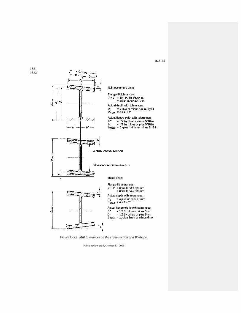
Code of Standard Practice for Steel Buildings and Bridges, <date> AMERICAN INSTITUTE OF STEEL CONSTRUCTION
Public review draft, October 13, 2015
16.3-34
1581 1582
Figure C-5.1. Mill tolerances on the cross-section of a W-shape.
Code of Standard Practice for Steel Buildings and Bridges, <date> AMERICAN INSTITUTE OF STEEL CONSTRUCTION
Public review draft, October 13, 2015
16.3-35
SECTION 6. SHOP FABRICATION AND DELIVERY 1583 1584 6.1. Identification of Material 1585 1586 6.1.1. The fabricator shall be able to demonstrate by written procedure and actual 1587
practice a method of material identification, visible up to the point of 1588 assembling members as follows: 1589
1590 (a) For shop-standard material, identification capability shall include shape 1591
designation. Representative material test reports shall be furnished by the 1592 fabricator if requested to do so by the owner’s designated representative 1593 for design, either in the contract documents or in separate written 1594 instructions given to the fabricator prior to ordering mill materials. 1595
(b) For material of grade other than shop-standard material, identification 1596 capability shall include shape designation and material grade. 1597 Representative material test reports shall be furnished by the fabricator if 1598 requested to do so by the owner’s designated representative for design, 1599 either in the contract documents or in separate written instructions given to 1600 the fabricator prior to ordering mill materials. 1601
(c) For material ordered in accordance with an ASTM supplement or other 1602 special material requirements in the contract documents, identification 1603 capability shall include shape designation, material grade, and heat number. 1604 The corresponding material test reports shall be furnished by the fabricator 1605 if requested to do so by the owner’s designated representative for design, 1606 either in the contract documents or in separate written instructions given to 1607 the fabricator prior to ordering mill materials. 1608
1609 Unless an alternative system is established in the fabricator’s written 1610
procedures, shop-standard material shall be as follows: 1611 1612 Material Shop-standard material grade 1613 W and WT ASTM A992 1614 M, S, MT and ST ASTM A36 1615 HP ASTM A572 grade 50 1616 L ASTM A36 1617 C and MC ASTM A36 1618 HSS ASTM A500 grade B 1619 Steel Pipe ASTM A53 grade B 1620 Plates and Bars ASTM A36 1621 1622
Commentary: 1623

Code of Standard Practice for Steel Buildings and Bridges, <date> AMERICAN INSTITUTE OF STEEL CONSTRUCTION
Public review draft, October 13, 2015
16.3-36
The requirements in Section 6.1.1(a) will suffice for most projects. When 1624 material is of a strength level that differs from the shop-standard grade, the 1625 requirements in Section 6.1.1(b) apply. When special material requirements 1626 apply, such as ASTM A6/A6M supplement S5 or S30 for CVN testing, ASTM 1627 A6/A6M supplement S8 for ultrasonic testing, or ASTM A588/A588M for 1628 atmospheric corrosion resistance, the requirements in Section 6.1.1(c) are 1629 applicable. 1630
1631 6.1.2. During fabrication, up to the point of assembling members, each piece of 1632
material that is ordered to special material requirements shall carry a 1633 fabricator’s identification mark or an original supplier’s identification mark. 1634 The fabricator’s identification mark shall be in accordance with the fabricator’s 1635 established material identification system, which shall be on record and 1636 available prior to the start of fabrication for the information of the owner’s 1637 designated representative for construction, the building-code authority and the 1638 inspector. 1639
1640 6.1.3. Members that are made of material that is ordered to special material 1641
requirements shall not be given the same assembling or erection mark as 1642 members made of other material, even if they are of identical dimensions and 1643 detail. 1644
1645 6.2. Preparation of Material 1646 1647 6.2.1. The thermal cutting of structural steel by hand-guided or mechanically guided 1648
means is permitted. 1649 1650 6.2.2. Surfaces that are specified as “finished” in the contract documents shall have a 1651
roughness height value measured in accordance with ASME B46.1 that is equal 1652 to or less than 500 μin. The use of any fabricating technique that produces such 1653 a finish is permitted. 1654
1655 Commentary: 1656 Most cutting processes, including friction sawing and cold sawing, and milling 1657 processes meet a surface roughness limitation of 500 μin per ASME B46.1. 1658
1659 6.3. Fitting and Fastening 1660 1661 6.3.1. Projecting elements of connection materials need not be straightened in the 1662
connecting plane, subject to the limitations in the AISC Specification. 1663 1664
Code of Standard Practice for Steel Buildings and Bridges, <date> AMERICAN INSTITUTE OF STEEL CONSTRUCTION
Public review draft, October 13, 2015
16.3-37
6.3.2. Backing bars and runoff tabs shall be used in accordance with AWS D1.1 as 1665 required to produce sound welds. The fabricator or erector need not remove 1666 backing bars or runoff tabs unless such removal is specified in the contract 1667 documents. When the removal of backing bars is specified in the contract 1668 documents, such removal shall meet the requirements in AWS D1.1. When the 1669 removal of runoff tabs is specified in the contract documents, hand flame-1670 cutting close to the edge of the finished member with no further finishing is 1671 permitted, unless other finishing is specified in the contract documents. 1672
1673 Commentary: 1674 In most cases, the treatment of backing bars and runoff tabs is left to the 1675 discretion of the owner’s designated representative for design. In some cases, 1676 treatment beyond the basic cases described in this Section may be required. As 1677 one example, special treatment is required for backing bars and runoff tabs in 1678 beam-to-column moment connections when the requirements in the AISC 1679 Seismic Provisions must be met. In all cases, the owner’s designated 1680 representative for design should specify the required treatments in the contract 1681 documents. 1682
1683 6.3.3. Unless otherwise noted in the fabrication documents, high-strength bolts for 1684
shop-attached connection material shall be installed in the shop in accordance 1685 with the requirements in the AISC Specification. 1686
1687 6.4. Fabrication Tolerances 1688
The tolerances on structural steel fabrication shall be in accordance with the 1689 requirements in Section 6.4.1 through 6.4.6. 1690
1691 Commentary: 1692 Fabrication tolerances are stipulated in several specifications and codes, each 1693 applicable to a specialized area of construction. Basic fabrication tolerances are 1694 stipulated in this Section. For architecturally exposed structural steel, see 1695 Section 10. Other specifications and codes are also commonly incorporated by 1696 reference in the contract documents, such as the AISC Specification, the RCSC 1697 Specification, AWS D1.1, and the AASHTO Specification. 1698
1699 6.4.1. For members that have both ends finished (see Section 6.2.2) for contact 1700
bearing, the variation in the overall length shall be equal to or less than Q in. [1 1701 mm]. For other members that frame to other structural steel elements, the 1702 variation in the detailed length shall be as follows: 1703
1704 (a) For members that are equal to or less than 30 ft [9 000 mm] in length, the 1705
variation shall be equal to or less than z in. [2 mm]. 1706
Code of Standard Practice for Steel Buildings and Bridges, <date> AMERICAN INSTITUTE OF STEEL CONSTRUCTION
Public review draft, October 13, 2015
16.3-38
(b) For members that are greater than 30 ft [9 000 mm] in length, the variation 1707 shall be equal to or less than 8 in. [3 mm]. 1708
1709 6.4.2. For straight and curved structural members, whether of a single standard 1710
structural shape or built-up, the permitted variation in specified straightness or 1711 curvature shall be as listed below. In all cases, completed members shall be free 1712 of twists (except as allowed by ASTM standards), bends, and open joints. Sharp 1713 kinks or sharp bends shall be cause for rejection. 1714
1715 (a) For straight structural members other than compression members, the variation 1716
in straightness shall be equal to or less than that specified for structural shapes 1717 in the applicable ASTM standards except when a smaller variation is specified 1718 in the contract documents. 1719 For straight compression members, the variation in straightness shall be equal 1720 to or less than 1/1000 of the axial length between working points. 1721
(b) For curved structural members, the variation in the chord length shall be as 1722 defined in paragraph 6.4.1. The variation in curvature measured at the middle 1723 ordinate shall be equal to or less than the permissible variations in straightness 1724 as specified in applicable ASTM standards for camber in the strong direction 1725 and sweep in the weak direction, inside or outside of the theoretical arc except 1726 when a smaller variation is specified in the contract documents. Should no 1727 applicable ASTM standard exist, the maximum variation in curvature measured 1728 at the middle ordinate shall be [1/8 in. x (total arc length in feet / 5’-0”)] for 1729 members 10’-0” or greater. For members less than 10’-0”, the permissible 1730 variation in curvature measured at the middle ordinate shall be ±1/8”. The 1731 middle ordinate is located between work points as shown in Figure C-6.1. 1732 1733 <Figure C-6.1 included as separate file> 1734
1735 Commentary: 1736 Curved structural members, as referred to in this section, are defined as those 1737 members intended to maintain a specified curvature while in use. This section 1738 does not apply to members specified for camber. The location of the arc length 1739 is defined by the contract drawings and may be either at the member’s inside 1740 radius, the outside radius, or the radius between work points. 1741
1742 (c) The tolerance on twist of members shall be individually determined and 1743
mutually agreed upon by the fabricator and owner’s designated representative 1744 for design. 1745 Commentary: 1746 ASTM A500 provides a twist tolerance for HSS and AWS D1.1 addresses twist 1747 of box members. These tolerances are required because these members are 1748
Code of Standard Practice for Steel Buildings and Bridges, <date> AMERICAN INSTITUTE OF STEEL CONSTRUCTION
Public review draft, October 13, 2015
16.3-39
torsionally stiff and twist generally cannot be removed in these shapes once it is 1749 present. Shapes of open cross section generally are not as stiff and do not have a 1750 similar tolerance. 1751 In an unspliced member, twist is generally a matter of serviceability or 1752 aesthetics. In a member that will be spliced, twist can affect erection and 1753 connection details should accommodate twist in the completed member. If 1754 deemed necessary, the required twist tolerance should be specified in the 1755 contract documents. 1756 1757
6.4.3. For beams that are detailed without specified camber, the member shall be 1758 fabricated so that, after erection, any incidental camber due to rolling or shop 1759 fabrication is upward. For trusses that are detailed without specified camber, the 1760 components shall be fabricated so that, after erection, any incidental camber in 1761 the truss due to rolling or shop fabrication is upward. 1762
1763 6.4.4. For beams that are specified in the contract documents with camber, beams 1764
received by the fabricator with 75% of the specified camber shall require no 1765 further cambering. Otherwise, the variation in camber shall be as follows: 1766
1767 (a) For beams that are equal to or less than 50 ft [15 000 mm] in length, the 1768
variation shall be equal to or less than minus zero / plus 2 in. [13 mm]. 1769 (b) For beams that are greater than 50 ft [15 000 mm] in length, the variation 1770
shall be equal to or less than minus zero / plus 2 in. plus 8 in. for each 10 1771 ft or fraction thereof [13 mm plus 3 mm for each 3 000 mm or fraction 1772 thereof] in excess of 50 ft [15 000 mm] in length. 1773
1774 For the purpose of inspection, camber shall be measured in the fabricator’s shop 1775 in the unstressed condition. 1776
1777 Commentary: 1778 There is no known way to inspect beam camber after the beam is received in the 1779 field because of factors that include: 1780 1781 (a) The release of stresses in members over time and in varying applications; 1782 (b) The effects of the dead weight of the member; 1783 (c) The restraint caused by the end connections in the erected state; and, 1784 (d) The effects of additional dead load that may ultimately be intended to be 1785
applied, if any. 1786 1787 Therefore, inspection of the fabricator’s work on beam camber must be done in 1788 the fabrication shop in the unstressed condition. 1789
1790
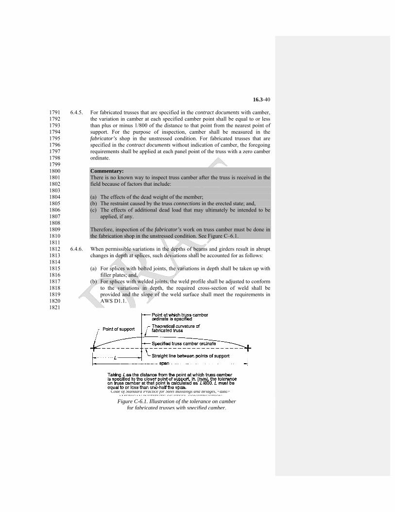
Code of Standard Practice for Steel Buildings and Bridges, <date> AMERICAN INSTITUTE OF STEEL CONSTRUCTION
Public review draft, October 13, 2015
16.3-40
6.4.5. For fabricated trusses that are specified in the contract documents with camber, 1791 the variation in camber at each specified camber point shall be equal to or less 1792 than plus or minus 1/800 of the distance to that point from the nearest point of 1793 support. For the purpose of inspection, camber shall be measured in the 1794 fabricator’s shop in the unstressed condition. For fabricated trusses that are 1795 specified in the contract documents without indication of camber, the foregoing 1796 requirements shall be applied at each panel point of the truss with a zero camber 1797 ordinate. 1798
1799 Commentary: 1800 There is no known way to inspect truss camber after the truss is received in the 1801 field because of factors that include: 1802 1803 (a) The effects of the dead weight of the member; 1804 (b) The restraint caused by the truss connections in the erected state; and, 1805 (c) The effects of additional dead load that may ultimately be intended to be 1806
applied, if any. 1807 1808 Therefore, inspection of the fabricator’s work on truss camber must be done in 1809 the fabrication shop in the unstressed condition. See Figure C–6.1. 1810
1811 6.4.6. When permissible variations in the depths of beams and girders result in abrupt 1812
changes in depth at splices, such deviations shall be accounted for as follows: 1813 1814
(a) For splices with bolted joints, the variations in depth shall be taken up with 1815 filler plates; and, 1816
(b) For splices with welded joints, the weld profile shall be adjusted to conform 1817 to the variations in depth, the required cross-section of weld shall be 1818 provided and the slope of the weld surface shall meet the requirements in 1819 AWS D1.1. 1820
1821
Figure C-6.1. Illustration of the tolerance on camber for fabricated trusses with specified camber.
Code of Standard Practice for Steel Buildings and Bridges, <date> AMERICAN INSTITUTE OF STEEL CONSTRUCTION
Public review draft, October 13, 2015
16.3-41
6.5. Shop Cleaning and Painting (see also Section 3.1.6) 1822 Structural steel that does not require shop paint shall be cleaned of oil and 1823
grease with solvent cleaners, and of dirt and other foreign material by sweeping 1824 with a fiber brush or other suitable means. For structural steel that is required to 1825 be shop painted, the requirements in Sections 6.5.1 through 6.5.4 shall apply. 1826
1827 Commentary: 1828 Extended exposure of unpainted structural steel that has been cleaned for the 1829 subsequent application of fire protection materials can be detrimental to the 1830 fabricated product. Most levels of cleaning require the removal of all loose mill 1831 scale, but permit some amount of tightly adhering mill scale. When a piece of 1832 structural steel that has been cleaned to an acceptable level is left exposed to a 1833 normal environment, moisture can penetrate behind the scale, and some “lifting” 1834 of the scale by the oxidation process is to be expected. Cleanup of “lifted” mill 1835 scale is not the responsibility of the fabricator, but is to be assigned by contract 1836 requirement to an appropriate contractor. 1837
Section 6.5.4 of this Code is not applicable to weathering steel, for 1838 which special cleaning specifications are always required in the contract 1839 documents. 1840
1841 6.5.1. The fabricator is not responsible for deterioration of the shop coat that may 1842
result from exposure to ordinary atmospheric conditions or corrosive conditions 1843 that are more severe than ordinary atmospheric conditions. 1844
1845 Commentary: 1846 The shop coat of paint is the prime coat of the protective system. It is intended 1847 as protection for only a short period of exposure in ordinary atmospheric 1848 conditions, and is considered a temporary and provisional coating. 1849
1850 6.5.2. Unless otherwise specified in the contract documents, the fabricator shall, as a 1851
minimum, hand clean the structural steel of loose rust, loose mill scale, dirt and 1852 other foreign matter, prior to painting, by means of wire brushing or by other 1853 methods elected by the fabricator, to meet the requirements of SSPC-SP2. If the 1854 fabricator’s workmanship on surface preparation is to be inspected by the 1855 inspector, such inspection shall be performed in a timely manner prior to the 1856 application of the shop coat. 1857
1858 Commentary: 1859 The selection of a paint system is a design decision involving many factors 1860 including: 1861 1862 (a) The owner’s preference; 1863
Code of Standard Practice for Steel Buildings and Bridges, <date> AMERICAN INSTITUTE OF STEEL CONSTRUCTION
Public review draft, October 13, 2015
16.3-42
(b) The service life of the structure; 1864 (c) The severity of environmental exposure; 1865 (d) The cost of both initial application and future renewals; and, 1866 (e) The compatibility of the various components that comprise the paint system 1867
(surface preparation, shop coat and subsequent coats). 1868 1869
Because the inspection of shop painting must be concerned with 1870 workmanship at each stage of the operation, the fabricator provides notice of 1871 the schedule of operations and affords the inspector access to the work site. 1872 Inspection must then be coordinated with that schedule so as to avoid delay of 1873 the scheduled operations. 1874
Acceptance of the prepared surface must be made prior to the 1875 application of the shop coat because the degree of surface preparation cannot be 1876 readily verified after painting. Time delay between surface preparation and the 1877 application of the shop coat can result in unacceptable deterioration of a 1878 properly prepared surface, necessitating a repetition of surface preparation. This 1879 is especially true with blast-cleaned surfaces. Therefore, to avoid potential 1880 deterioration of the surface, it is assumed that surface preparation is accepted 1881 unless it is inspected and rejected prior to the scheduled application of the shop 1882 coat. 1883
The shop coat in any paint system is designed to maximize the wetting 1884 and adherence characteristics of the paint, usually at the expense of its 1885 weathering capabilities. Deterioration of the shop coat normally begins 1886 immediately after exposure to the elements and worsens as the duration of 1887 exposure is extended. Consequently, extended exposure of the shop coat will 1888 likely lead to its deterioration and may necessitate repair, possibly including the 1889 repetition of surface preparation and shop coat application in limited areas. With 1890 the introduction of high-performance paint systems, avoiding delay in the 1891 application of the shop coat has become more critical. High-performance paint 1892 systems generally require a greater degree of surface preparation, as well as 1893 early application of weathering protection for the shop coat. 1894
Since the fabricator does not control the selection of the paint system, 1895 the compatibility of the various components of the total paint system, or the 1896 length of exposure of the shop coat, the fabricator cannot guarantee the 1897 performance of the shop coat or any other part of the system. Instead, the 1898 fabricator is responsible only for accomplishing the specified surface 1899 preparation and for applying the shop coat (or coats) in accordance with the 1900 contract documents. 1901
This Section stipulates that the structural steel is to be cleaned to meet 1902 the requirements in SSPC-SP2. This stipulation is not intended to represent an 1903 exclusive cleaning level, but rather the level of surface preparation that will be 1904 furnished unless otherwise specified in the contract documents if the structural 1905 steel is to be painted. 1906
Code of Standard Practice for Steel Buildings and Bridges, <date> AMERICAN INSTITUTE OF STEEL CONSTRUCTION
Public review draft, October 13, 2015
16.3-43
1907 6.5.3. Unless otherwise specified in the contract documents, paint shall be applied by 1908
brushing, spraying, rolling, flow coating, dipping or other suitable means, at the 1909 election of the fabricator. When the term “shop coat”, “shop paint” or other 1910 equivalent term is used with no paint system specified, the fabricator’s standard 1911 shop paint shall be applied to a minimum dry-film thickness of one mil [25 m]. 1912
1913 6.5.4. Touch-up of abrasions caused by handling after painting shall be the 1914
responsibility of the contractor that performs touch-up in the field or field 1915 painting. 1916
1917 Commentary: 1918 Touch-up in the field and field painting are not normally part of the fabricator’s 1919 or the erector’s contract. 1920
1921 6.6. Marking and Shipping of Materials 1922 1923 6.6.1. Unless otherwise specified in the contract documents, erection marks shall be 1924
applied to the structural steel members by painting or other suitable means. 1925 1926 6.6.2. Bolt assemblies and loose bolts, nuts and washers shall be shipped in separate 1927
closed containers according to length and diameter, as applicable. Pins and other 1928 small parts and packages of bolts, nuts and washers shall be shipped in boxes, 1929 crates, kegs or barrels. A list and description of the material shall appear on the 1930 outside of each closed container. 1931
1932 Commentary: 1933 In most cases bolts, nuts and other components in a fastener assembly can be 1934 shipped loose in separate containers. However, there are exceptions: 1935 1936 ASTM F1852/F1852M and F2280/F2280M twist-off-type tension-control 1937
bolt assemblies must be assembled and shipped in containers according to 1938 grade, length and diameter. 1939
Galvanized ASTM A325/A325M bolts and their corresponding ASTM 1940 A563/A563M nuts must be shipped in the same container according to 1941 length and diameter. 1942
1943 See these ASTM standards for the applicable requirements and the RCSC 1944 Specification for further explanation. 1945
1946 6.7. Delivery of Materials 1947 1948
Code of Standard Practice for Steel Buildings and Bridges, <date> AMERICAN INSTITUTE OF STEEL CONSTRUCTION
Public review draft, October 13, 2015
16.3-44
6.7.1. Fabricated structural steel shall be delivered in a sequence that will permit 1949 efficient and economical fabrication and erection, and that is consistent with 1950 requirements in the contract documents. If the owner or owner’s designated 1951 representative for construction wishes to prescribe or control the sequence of 1952 delivery of materials, that entity shall specify the required sequence in the 1953 contract documents. If the owner’s designated representative for construction 1954 contracts separately for delivery and for erection, the owner’s designated 1955 representative for construction shall coordinate planning between contractors. 1956
1957 6.7.2. Anchor rods, washers, nuts and other anchorage or grillage materials that are to 1958
be built into concrete or masonry shall be shipped so that they will be available 1959 when needed. The owner’s designated representative for construction shall 1960 allow the fabricator sufficient time to fabricate and ship such materials before 1961 they are needed. 1962
1963 6.7.3. If any shortage is claimed relative to the quantities of materials that are shown in 1964
the shipping statements, the owner’s designated representative for construction 1965 or the erector shall promptly notify the fabricator so that the claim can be 1966 investigated. 1967
1968 Commentary: 1969 The quantities of material that are shown in the shipping statement are 1970 customarily accepted as correct by the owner’s designated representative for 1971 construction, the fabricator and the erector. 1972
1973 6.7.4. Unless otherwise specified in the contract documents, and subject to the 1974
approved approval documents, the fabricator shall limit the number of field 1975 splices to that consistent with minimum project cost. 1976
1977 Commentary: 1978 This Section recognizes that the size and weight of structural steel assemblies 1979 may be limited by shop capabilities, the permissible weight and clearance 1980 dimensions of available transportation or job-site conditions. 1981
1982 6.7.5. If material arrives at its destination in damaged condition, the receiving entity 1983
shall promptly notify the fabricator and carrier prior to unloading the material, 1984 or promptly upon discovery prior to erection. 1985
1986
Code of Standard Practice for Steel Buildings and Bridges, <date> AMERICAN INSTITUTE OF STEEL CONSTRUCTION
Public review draft, October 13, 2015
16.3-45
SECTION 7. ERECTION 1987 1988 7.1. Method of Erection 1989
Fabricated structural steel shall be erected using methods and a sequence that 1990 will permit efficient and economical performance of erection, and that is 1991 consistent with the requirements in the contract documents. If the owner or 1992 owner’s designated representative for construction wishes to prescribe or 1993 control the method and/or sequence of erection, or specifies that certain 1994 members cannot be erected in their normal sequence, that entity shall specify the 1995 required method and sequence in the contract documents. If the owner’s 1996 designated representative for construction contracts separately for fabrication 1997 services and for erection services, the owner’s designated representative for 1998 construction shall coordinate planning between contractors. 1999
2000 Commentary: 2001 Design modifications are sometimes requested by the erector to allow or 2002 facilitate the erection of the structural steel frame. When this is the case, the 2003 erector should notify the fabricator prior to the preparation of the approval 2004 documents so that the fabricator may refer the erector’s request to the owner’s 2005 designated representatives for design and construction for resolution. 2006
2007 7.2. Job-Site Conditions 2008
The owner’s designated representative for construction shall provide and 2009 maintain the following for the fabricator and the erector: 2010 2011 (a) Adequate access roads into and through the job site for the safe delivery 2012
and movement of the material to be erected and of derricks, cranes, trucks 2013 and other necessary equipment under their own power; 2014
(b) A firm, properly graded, drained, convenient and adequate space at the job 2015 site for the operation of the erector’s equipment, free from overhead 2016 obstructions, such as power lines, telephone lines or similar conditions; and, 2017
(c) Adequate storage space, when the structure does not occupy the full 2018 available job site, to enable the fabricator and the erector to operate at 2019 maximum practical speed. 2020
2021 Otherwise, the owner’s designated representative for construction shall inform 2022 the fabricator and the erector of the actual job-site conditions and/or special 2023 delivery requirements prior to bidding. 2024
2025 7.3. Foundations, Piers and Abutments 2026
Code of Standard Practice for Steel Buildings and Bridges, <date> AMERICAN INSTITUTE OF STEEL CONSTRUCTION
Public review draft, October 13, 2015
16.3-46
The accurate location, strength and suitability of, and access to, all foundations, 2027 piers and abutments shall be the responsibility of the owner’s designated 2028 representative for construction. 2029
2030 7.4. Lines and Bench Marks 2031
The owner’s designated representative for construction shall be responsible for 2032 the accurate location of lines and benchmarks at the job site and shall furnish the 2033 erector with a plan that contains all such information. The owner’s designated 2034 representative for construction shall establish offset lines and reference 2035 elevations at each level for the erector’s use in the positioning of adjustable 2036 items (see Section 7.13.1.3), if any. 2037
2038 7.5. Installation of Anchor Rods, Foundation Bolts and Other Embedded Items 2039 2040 7.5.1. Anchor rods, foundation bolts and other embedded items shall be set by the 2041
owner’s designated representative for construction in accordance with 2042 embedment documents that have been approved by the owner’s designated 2043 representatives for design and construction. The variation in location of these 2044 items from the dimensions shown in the approved embedment documents shall 2045 be as follows: 2046
2047 (a) The variation in vertical dimension from the specified top of anchor rod 2048
location shall be equal to or less than plus or minus 1/2 in. [13 mm].. 2049 (b) The variation in horizontal dimension from specified position each of 2050
anchor rod centerline along its projection above the concrete shall be less 2051 than or equal to the dimensions given for the anchor rod diameters listed as 2052 follows: 2053 2054 Anchor rod diameter, in. (mm) Tolerance, in. (mm) 2055 3/4 and 7/8 (19 and 22) ± 1/4 (6) 2056 1, 1-1/4, 1-1/2 (25, 32, 37) ± 3/8 (10) 2057 1- 3/4, 2, 2-1/2 (45, 53, 65) ± 1/2 (13mm) 2058 2059
Commentary: 2060 The tolerances established in this Section have been selected for compatibility 2061 with the holes sizes that are recommended for base plates in the AISC Steel 2062 Construction Manual. If special conditions require more restrictive tolerances, 2063 such as for smaller holes, the required tolerances should be stated in the contract 2064 documents. When the anchor rods are set in sleeves, the adjustment provided 2065 may be used to satisfy the required anchor-rod setting tolerances. 2066
2067
Code of Standard Practice for Steel Buildings and Bridges, <date> AMERICAN INSTITUTE OF STEEL CONSTRUCTION
Public review draft, October 13, 2015
16.3-47
7.5.2. Unless otherwise specified in the contract documents, anchor rods shall be set 2068 with their longitudinal axis perpendicular to the theoretical bearing surface. 2069
2070 7.5.3. Embedded items and connection materials that are part of the work of other 2071
trades, but that will receive structural steel, shall be located and set by the 2072 owner’s designated representative for construction in accordance with an 2073 approved embedment drawing. The variation in location of these items shall be 2074 limited to a magnitude that is consistent with the tolerances that are specified in 2075 Section 7.13 for the erection of the structural steel. 2076
2077 7.5.4. All work that is performed by the owner’s designated representative for 2078
construction shall be completed so as not to delay or interfere with the work of 2079 the fabricator and the erector. The owner’s designated representative for 2080 construction shall conduct a survey of the as-built locations of anchor rods, 2081 foundation bolts and other embedded items, and shall verify that all items 2082 covered in Section 7.5 meet the corresponding tolerances. When corrective 2083 action is necessary, the owner’s designated representative for construction shall 2084 obtain the guidance and approval of the owner’s designated representative for 2085 design. 2086
2087 Commentary: 2088 Few fabricators or erectors have the capability to provide this survey. Under 2089 standard practice, it is the responsibility of others. 2090
2091 7.6. Installation of Bearing Devices 2092
All leveling plates, leveling nuts and washers and loose base and bearing plates 2093 that can be handled without a derrick or crane are set to line and grade by the 2094 owner’s designated representative for construction. Loose base and bearing 2095 plates that require handling with a derrick or crane shall be set by the erector to 2096 lines and grades established by the owner’s designated representative for 2097 construction. The fabricator shall clearly scribe loose base and bearing plates 2098 with lines or other suitable marks to facilitate proper alignment. 2099
Promptly after the setting of bearing devices, the owner’s designated 2100 representative for construction shall check them for line and grade. The 2101 variation in elevation relative to the established grade for all bearing devices 2102 shall be equal to or less than plus or minus 8 in. [3 mm]. The final location of 2103 bearing devices shall be the responsibility of the owner’s designated 2104 representative for construction. 2105
2106 Commentary: 2107 The 8 in. [3 mm] tolerance on elevation of bearing devices relative to 2108 established grades is provided to permit some variation in setting bearing 2109

Code of Standard Practice for Steel Buildings and Bridges, <date> AMERICAN INSTITUTE OF STEEL CONSTRUCTION
Public review draft, October 13, 2015
16.3-48
devices, and to account for the accuracy that is attainable with standard 2110 surveying instruments. The use of leveling plates larger than 22 in. by 22 in. 2111 [550 mm by 550 mm] is discouraged and grouting is recommended with larger 2112 sizes. For the purposes of erection stability, the use of leveling nuts and washers 2113 is discouraged when base plates have less than four anchor rods. 2114
2115 7.7. Grouting 2116
Grouting shall be the responsibility of the owner’s designated representative for 2117 construction. Leveling plates and loose base and bearing plates shall be 2118 promptly grouted after they are set and checked for line and grade. Columns 2119 with attached base plates, beams with attached bearing plates and other similar 2120 members with attached bearing devices that are temporarily supported on 2121 leveling nuts and washers, shims or other similar leveling devices, shall be 2122 promptly grouted after the structural steel frame or portion thereof has been 2123 plumbed. 2124
2125 Commentary: 2126 In the majority of structures the vertical load from the column bases is 2127 transmitted to the foundations through structural grout. In general, there are 2128 three methods by which support is provided for column bases during erection: 2129 2130 (a) Pre-grouted leveling plates or loose base plates; 2131 (b) Shims; and, 2132 (c) Leveling nuts and washers on the anchor rods beneath the column base. 2133 2134 Standard practice provides that loose base plates and leveling plates are to be 2135 grouted as they are set. Bearing devices that are set on shims or leveling nuts are 2136 grouted after plumbing, which means that the weight of the erected structural 2137 steel frame is supported on the shims or washers, nuts and anchor rods. The 2138 erector must take care to ensure that the load that is transmitted in this 2139 temporary condition does not exceed the strength of the shims or washers, nuts 2140 and anchor rods. These considerations are presented in greater detail in AISC 2141 Design Guides No. 1 and 10. 2142
2143 7.8. Field Connection Material 2144 2145 7.8.1. The fabricator shall provide field connection details that are consistent with the 2146
requirements in the contract documents and that will, in the fabricator’s 2147 opinion, result in economical fabrication and erection. 2148
2149
Code of Standard Practice for Steel Buildings and Bridges, <date> AMERICAN INSTITUTE OF STEEL CONSTRUCTION
Public review draft, October 13, 2015
16.3-49
7.8.2. When the fabricator is responsible for erecting the structural steel, the 2150 fabricator shall furnish all materials that are required for both temporary and 2151 permanent connection of the component parts of the structural steel frame. 2152
2153 7.8.3. When the erection of the structural steel is not performed by the fabricator, the 2154
fabricator shall furnish the following field connection material: 2155 2156
(a) Bolts, nuts and washers of the required grade, type and size and in 2157 sufficient quantity for all structural steel-to-structural steel field 2158 connections that are to be permanently bolted, including an extra 2 percent 2159 of each bolt size (diameter and length); 2160
(b) Shims that are shown as necessary for make-up of permanent structural 2161 steel-to-structural steel field connections; and, 2162
(c) Backing bars and run-off tabs that are required for field welding. 2163 2164 7.8.4. The erector shall furnish all welding electrodes, fit-up bolts and drift pins used 2165
for the erection of the structural steel. 2166 2167
Commentary: 2168 See the Commentary for Section 2.2. 2169
2170 7.9. Loose Material 2171
Unless otherwise specified in the contract documents, loose structural steel 2172 items that are not connected to the structural steel frame shall be set by the 2173 owner’s designated representative for construction without assistance from the 2174 erector. 2175
2176 7.10. Temporary Support of Structural Steel Frames 2177 2178 7.10.1. The owner’s designated representative for design shall identify the following in 2179
the contract documents: 2180 2181
(a) The lateral-load-resisting system and connecting diaphragm elements that 2182 provide for lateral strength and stability in the completed structure; and, 2183
(b) Any special erection conditions or other considerations that are required by 2184 the design concept, such as the use of shores, jacks or loads that must be 2185 adjusted as erection progresses to set or maintain camber, position within 2186 specified tolerances or prestress. 2187
2188 Commentary: 2189 The intent of Section 7.10.1 of the Code is to alert the owner’s designated 2190 representative for construction and the erector of the means for lateral load 2191
Code of Standard Practice for Steel Buildings and Bridges, <date> AMERICAN INSTITUTE OF STEEL CONSTRUCTION
Public review draft, October 13, 2015
16.3-50
resistance in the completed structure so that appropriate planning can occur for 2192 construction of the building. Examples of a description of the lateral load 2193 resisting system as required by 7.10.1(a) are shown below. 2194
Example 1 is an all-steel building with a composite metal deck and 2195 concrete floor system. All lateral load resistance is provided by welded moment 2196 frames in each orthogonal building direction. One suitable description of this 2197 lateral load resisting system is: 2198
All lateral load resistance and stability of the building in the completed 2199 structure is provided by moment frames with welded beam to column 2200 connections framed in each orthogonal direction (see plan sheets for locations). 2201 The composite metal deck and concrete floors serve as horizontal diaphragms 2202 that distribute the lateral wind and seismic forces horizontally to the vertical 2203 moment frames. The vertical moment frames carry the applied lateral loads to 2204 the building foundation. 2205
Example 2 is a steel-framed building with a composite metal deck and 2206 concrete floor system. All beam-to-column connections are simple connections 2207 and all lateral load resistance is provided by reinforced concrete shear walls in 2208 the building core and in the stair wells. One suitable description of this lateral 2209 load resisting system is: 2210
All lateral load resistance and stability of the building in the completed 2211 structure is provided exclusively by cast-in-place reinforced concrete shear 2212 walls in the building core and stair wells (see plan sheets for locations). These 2213 walls provide all lateral load resistance in each orthogonal building direction. 2214 The composite metal deck and concrete floors serve as horizontal diaphragms 2215 that distribute the lateral wind and seismic forces horizontally to the concrete 2216 shear walls. The concrete shear walls carry the applied lateral loads to the 2217 building foundation. 2218
See also Commentary Section 7.10.3. 2219 2220 Section 7.10.1(b) is intended to apply to special requirements inherent in the 2221 design concept that could not otherwise be known by the erector. Such 2222 conditions might include designs that require the use of shores or jacks to impart 2223 a load or to obtain a specific elevation or position in a subsequent step of the 2224 erection process in a sequentially erected structure or member. These 2225 requirements would not be apparent to an erector, and must be identified so the 2226 erector can properly bid, plan and perform the erection. 2227 2228 The erector is responsible for installation of all members (including cantilevered 2229 members) to the specified plumbness, elevation, and alignment within the 2230 erection tolerances specified in this Code. The erector must provide all 2231

Code of Standard Practice for Steel Buildings and Bridges, <date> AMERICAN INSTITUTE OF STEEL CONSTRUCTION
Public review draft, October 13, 2015
16.3-51
temporary supports and devices to maintain elevation or position within these 2232 tolerances. These works are part of the means and methods of the erector and 2233 the owner’s designated representative for design need not specify these methods 2234 or related equipment. 2235 2236 See also the preset requirements for cantilevered members in Section 3.1. 2237
2238 7.10.2. The owner’s designated representative for construction shall indicate to the 2239
erector prior to bidding, the installation schedule for non-structural steel 2240 elements of the lateral-load-resisting system and connecting diaphragm elements 2241 identified by the owner’s designated representative for design in the contract 2242 documents. 2243
2244 Commentary: 2245 See Commentary Section 7.10.3. 2246
2247 7.10.3. Based upon the information provided in accordance with Sections 7.10.1 and 2248
7.10.2, the erector shall determine, furnish and install all temporary supports, 2249 such as temporary guys, beams, falsework, cribbing or other elements required 2250 for the erection operation. These temporary supports shall be sufficient to secure 2251 the bare structural steel framing or any portion thereof against loads that are 2252 likely to be encountered during erection, including those due to wind and those 2253 that result from erection operations. 2254
The erector need not consider loads during erection that result from the 2255 performance of work by, or the acts of, others, except as specifically identified 2256 by the owner’s designated representatives for design and construction, nor 2257 those that are unpredictable, such as loads due to hurricane, tornado, earthquake, 2258 explosion or collision. 2259
Temporary supports that are required during or after the erection of the 2260 structural steel frame for the support of loads caused by non-structural steel 2261 elements, including cladding, interior partitions and other such elements that 2262 will induce or transmit loads to the structural steel frame during or after 2263 erection, shall be the responsibility of others. 2264 2265 Commentary: 2266 Many structural steel frames have lateral-load-resisting systems that are 2267 activated during the erection process. Such lateral-load-resisting systems may 2268 consist of welded moment frames, braced frames or, in some instances, columns 2269 that cantilever from fixed-base foundations. Such frames are normally braced 2270 with temporary guys that, together with the steel deck floor and roof 2271 diaphragms, or other diaphragm bracing that may be included as part of the 2272 design, provide stability during the erection process. The guy cables are also 2273 commonly used to plumb the structural steel frame. The erector normally 2274
Code of Standard Practice for Steel Buildings and Bridges, <date> AMERICAN INSTITUTE OF STEEL CONSTRUCTION
Public review draft, October 13, 2015
16.3-52
furnishes and installs the required temporary supports and bracing to secure the 2275 bare structural steel frame, or portion thereof, during the erection process. 2276 When erection bracing drawings are required in the contract documents, those 2277 drawings show this information. 2278 If the owner’s designated representative for construction determines 2279 that steel decking is not installed by the erector, temporary diaphragm bracing 2280 may be required if a horizontal diaphragm is not available to distribute loads to 2281 the vertical and lateral load resisting system. If the steel deck will not be 2282 available as a diaphragm during structural steel erection, the owner’s designated 2283 representative for construction must communicate this condition to the erector 2284 prior to bidding. If such diaphragm bracing is required, it must be furnished and 2285 installed by the erector. 2286
Sometimes structural systems that are employed by the owner’s 2287 designated representative for design rely upon other elements besides the 2288 structural steel frame for lateral-load resistance. For instance, concrete or 2289 masonry shear walls or precast spandrels may be used to provide resistance to 2290 vertical and lateral loads in the completed structure. Because these situations 2291 may not be obvious to the contractor or the erector, it is required in this Code 2292 that the owner’s designated representative for design must identify such 2293 situations in the contract documents. Similarly, if a structure is designed so that 2294 special erection techniques are required, such as jacking to impose certain loads 2295 or position during erection, it is required in this Code that such requirements be 2296 specifically identified in the contract documents. 2297
In some instances, the owner’s designated representative for design 2298 may elect to show erection bracing in the structural design documents. When 2299 this is the case, the owner’s designated representative for design should then 2300 confirm that the bracing requirements were understood by review and approval 2301 of the erection documents during the submittal process. 2302
Sometimes during construction of a building, collateral building 2303 elements, such as exterior cladding, may be required to be installed on the bare 2304 structural steel frame prior to completion of the lateral-load-resisting system. 2305 These elements may increase the potential for lateral loads on the temporary 2306 supports. Such temporary supports may also be required to be left in place after 2307 the structural steel frame has been erected. Special provisions should be made 2308 by the owner’s designated representative for construction for these conditions. 2309 2310
7.10.4. All temporary supports that are required for the erection operation and furnished 2311 and installed by the erector shall remain the property of the erector and shall not 2312 be modified, moved or removed without the consent of the erector. Temporary 2313 supports provided by the erector shall remain in place until the portion of the 2314 structural steel frame that they brace is complete and the lateral-load-resisting 2315 system and connecting diaphragm elements identified by the owner’s designated 2316 representative for design in accordance with Section 7.10.1 are installed. 2317
Code of Standard Practice for Steel Buildings and Bridges, <date> AMERICAN INSTITUTE OF STEEL CONSTRUCTION
Public review draft, October 13, 2015
16.3-53
Temporary supports that are required to be left in place after the completion of 2318 structural steel erection shall be removed when no longer needed by the 2319 owner’s designated representative for construction and returned to the erector 2320 in good condition. 2321
2322 7.11. Safety Protection 2323 2324 7.11.1. The erector shall provide floor coverings, handrails, walkways and other safety 2325
protection for the erector’s personnel as required by law and the applicable 2326 safety regulations. Unless otherwise specified in the contract documents, the 2327 erector is permitted to remove such safety protection from areas where the 2328 erection operations are completed. 2329
2330 7.11.2. When safety protection provided by the erector is left in an area for the use of 2331
other trades after the structural steel erection activity is completed, the owner’s 2332 designated representative for construction shall: 2333
2334 (a) Accept responsibility for and maintain this protection; 2335 (b) Indemnify the fabricator and the erector from damages that may be 2336
incurred from the use of this protection by other trades; 2337 (c) Ensure that this protection is adequate for use by other affected trades; 2338 (d) Ensure that this protection complies with applicable safety regulations when 2339
being used by other trades; and, 2340 (e) Remove this protection when it is no longer required and return it to the 2341
erector in the same condition as it was received. 2342 2343 7.11.3. Safety protection for other trades that are not under the direct employment of the 2344
erector shall be the responsibility of the owner’s designated representative for 2345 construction. 2346
2347 7.11.4. When permanent steel decking is used for protective flooring and is installed by 2348
the owner’s designated representative for construction, all such work shall be 2349 scheduled and performed in a timely manner so as not to interfere with or delay 2350 the work of the fabricator or the erector. The sequence of installation that is 2351 used shall meet all safety regulations. 2352
2353 7.11.5. Unless the interaction and safety of activities of others, such as construction by 2354
others or the storage of materials that belong to others, are coordinated with the 2355 work of the erector by the owner’s designated representative for construction, 2356 such activities shall not be permitted until the erection of the structural steel 2357 frame or portion thereof is completed by the erector and accepted by the 2358 owner’s designated representative for construction. 2359
2360

Code of Standard Practice for Steel Buildings and Bridges, <date> AMERICAN INSTITUTE OF STEEL CONSTRUCTION
Public review draft, October 13, 2015
16.3-54
7.12. Structural Steel Frame Tolerances 2361 The accumulation of the mill tolerances and fabrication tolerances shall not 2362 cause the erection tolerances to be exceeded. 2363
2364 Commentary: 2365 In editions of this Code previous to the 2005 edition, it was stated that 2366 “…variations are deemed to be within the limits of good practice when they do 2367 not exceed the cumulative effect of rolling tolerances, fabricating tolerances and 2368 erection tolerances.” It is recognized in the current provision in this Section that 2369 accumulations of mill tolerances and fabrication tolerances generally occur 2370 between the locations at which erection tolerances are applied, and not at the 2371 same locations. 2372
2373 2374 7.13. Erection Tolerances 2375
Erection tolerances shall be defined relative to member working points and 2376 working lines, which shall be defined as follows: 2377
2378 (a) For members other than horizontal members, the member work point shall 2379
be the actual center of the member at each end of the shipping piece. 2380 (b) For horizontal members, the working point shall be the actual centerline of 2381
the top flange or top surface at each end. 2382 (c) The member working line shall be the straight line that connects the 2383
member working points. 2384 2385 The substitution of other working points is permitted for ease of reference, 2386 provided they are based upon the above definitions. 2387 The tolerances on structural steel erection shall be in accordance with 2388 the requirements in Sections 7.13.1 through 7.13.3. 2389 2390 Commentary: 2391 The erection tolerances defined in this Section have been developed through 2392 long-standing usage as practical criteria for the erection of structural steel. 2393 Erection tolerances were first defined in the 1924 edition of this Code in Section 2394 7(f), “Plumbing Up.” With the changes that took place in the types and use of 2395 materials in building construction after World War II, and the increasing 2396 demand by architects and owners for more specific tolerances, AISC adopted 2397 new standards for erection tolerances in Section 7(h) of the March 15, 1959 2398 edition of this Code. Experience has proven that those tolerances can be 2399 economically obtained. 2400
Differential column shortening may be a consideration in design and 2401 construction. In some cases, it may occur due to variability in the accumulation 2402 of dead load among different columns (see Figure C–7.1). In other cases, it may 2403
Code of Standard Practice for Steel Buildings and Bridges, <date> AMERICAN INSTITUTE OF STEEL CONSTRUCTION
Public review draft, October 13, 2015
16.3-55
be characteristic of the structural system that is employed in the design. 2404 Consideration of the effects of differential column shortening may be very 2405 important, such as when the slab thickness is reduced, when electrical and other 2406 similar fittings mounted on the structural steel are intended to be flush with the 2407 finished floor and when there is little clearance between bottoms of beams and 2408 the tops of door frames or ductwork. 2409
The effects of the deflection of transfer girders and trusses on the 2410 position of columns and hangers supported from them may be a consideration in 2411 design and construction. As in the case of differential column shortening, the 2412 deflection of these supporting members during and after construction will affect 2413 the position and alignment of the framing tributary to these transfer members. 2414 2415 (Commentary continues after figures) 2416
2417

Code of Standard Practice for Steel Buildings and Bridges, <date> AMERICAN INSTITUTE OF STEEL CONSTRUCTION
Public review draft, October 13, 2015
16.3-56
2418
Figure C-7.1. Effects of differential column shortening.
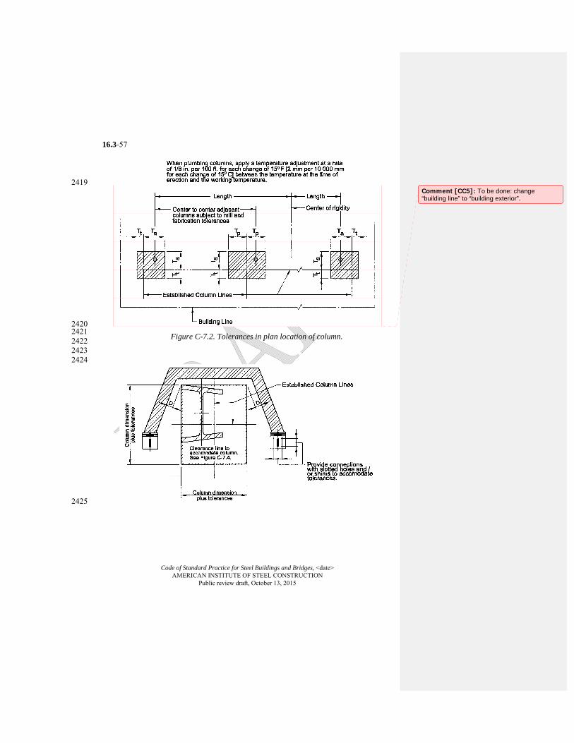
Code of Standard Practice for Steel Buildings and Bridges, <date> AMERICAN INSTITUTE OF STEEL CONSTRUCTION
Public review draft, October 13, 2015
16.3-57
2419
2420 2421 2422 2423 2424
2425
Figure C-7.2. Tolerances in plan location of column.
Comment [CC5]: To be done: change “building line” to “building exterior”.
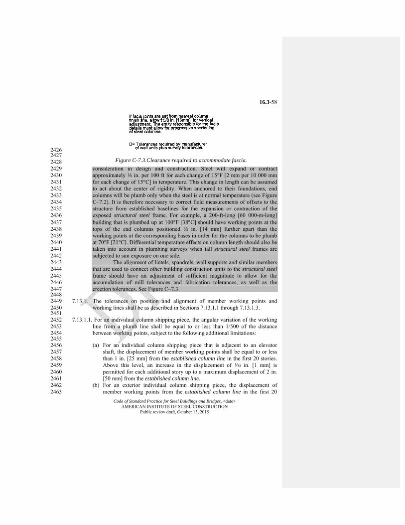
Code of Standard Practice for Steel Buildings and Bridges, <date> AMERICAN INSTITUTE OF STEEL CONSTRUCTION
Public review draft, October 13, 2015
16.3-58
2426 2427
Expansion and contraction in a structural steel frame may be a 2428 consideration in design and construction. Steel will expand or contract 2429 approximately 8 in. per 100 ft for each change of 15°F [2 mm per 10 000 mm 2430 for each change of 15°C] in temperature. This change in length can be assumed 2431 to act about the center of rigidity. When anchored to their foundations, end 2432 columns will be plumb only when the steel is at normal temperature (see Figure 2433 C–7.2). It is therefore necessary to correct field measurements of offsets to the 2434 structure from established baselines for the expansion or contraction of the 2435 exposed structural steel frame. For example, a 200-ft-long [60 000-m-long] 2436 building that is plumbed up at 100°F [38C] should have working points at the 2437 tops of the end columns positioned 2 in. [14 mm] further apart than the 2438 working points at the corresponding bases in order for the columns to be plumb 2439 at 70°F [21°C]. Differential temperature effects on column length should also be 2440 taken into account in plumbing surveys when tall structural steel frames are 2441 subjected to sun exposure on one side. 2442
The alignment of lintels, spandrels, wall supports and similar members 2443 that are used to connect other building construction units to the structural steel 2444 frame should have an adjustment of sufficient magnitude to allow for the 2445 accumulation of mill tolerances and fabrication tolerances, as well as the 2446 erection tolerances. See Figure C–7.3. 2447
2448 7.13.1. The tolerances on position and alignment of member working points and 2449
working lines shall be as described in Sections 7.13.1.1 through 7.13.1.3. 2450 2451 7.13.1.1. For an individual column shipping piece, the angular variation of the working 2452
line from a plumb line shall be equal to or less than 1/500 of the distance 2453 between working points, subject to the following additional limitations: 2454
2455 (a) For an individual column shipping piece that is adjacent to an elevator 2456
shaft, the displacement of member working points shall be equal to or less 2457 than 1 in. [25 mm] from the established column line in the first 20 stories. 2458 Above this level, an increase in the displacement of Q in. [1 mm] is 2459 permitted for each additional story up to a maximum displacement of 2 in. 2460 [50 mm] from the established column line. 2461
(b) For an exterior individual column shipping piece, the displacement of 2462 member working points from the established column line in the first 20 2463
Figure C-7.3.Clearance required to accommodate fascia.
Code of Standard Practice for Steel Buildings and Bridges, <date> AMERICAN INSTITUTE OF STEEL CONSTRUCTION
Public review draft, October 13, 2015
16.3-59
stories shall be equal to or less than 1 in. [25 mm] toward and 2 in. [50 mm] 2464 away from the building exterior. Above this level, an increase in the 2465 displacement of z in. [2 mm] is permitted for each additional story up to a 2466 maximum displacement of 2 in. [50 mm] toward and 3 in. [75 mm] away 2467 from the building exterior. 2468
2469 Commentary: 2470 The limitations that are described in this Section and illustrated in Figures 2471 C–7.4 and C–7.5 make it possible to maintain built-in-place or 2472 prefabricated facades in a true vertical plane up to the 20th story, if 2473 connections that provide for 3 in. [75 mm] of adjustment are used. Above 2474 the 20th story, the facade may be maintained within z in. [2 mm] per story 2475 with a maximum total deviation of 1 in. [25 mm] from a true vertical plane, 2476 if connections that provide for 3 in. [75 mm] of adjustment are used. 2477 Connections that permit adjustments of plus 2 in. [50 mm] to minus 3 in. 2478 [75 mm] (5 in. [125 mm] total) will be necessary in cases where it is desired 2479 to construct the facade to a true vertical plane above the 20th story. 2480
2481 (c) For an exterior individual column shipping piece, the member working 2482
points at any splice level for multi-tier buildings and at the tops of columns 2483 for single-tier buildings shall fall within a horizontal envelope, parallel to 2484 the exterior established column line, that is equal to or less than 12 in. [38 2485 mm] wide for buildings up to 300 ft [90 000 mm] in length. An increase in 2486 the width of this horizontal envelope of 2 in. [13 mm] is permitted for each 2487 additional 100 ft [30 000 m] in length up to a maximum width of 3 in. [75 2488 mm]. 2489
2490 Commentary: 2491 This Section limits the position of exterior column working points at any 2492 given splice elevation to a narrow horizontal envelope parallel to the 2493 exterior established column line (see Figure C–7.6). This envelope is 2494 limited to a width of 12 in. [38 mm], normal to the exterior established 2495 column line, in up to 300 ft [90 000 mm] of building length. The horizontal 2496 location of this envelope is not necessarily directly above or below the 2497 corresponding envelope at the adjacent splice elevations, but should be 2498 within the limitation of the 1 in 500 plumbness tolerance specified for the 2499 controlling columns (see Figure C–7.5). 2500
2501 (d) For an exterior column shipping piece, the displacement of member 2502
working points from the established column line, that is nominally parallel 2503 to the building exterior, shall be equal to or less than 2 in. [50 mm] in the 2504 first 20 stories. Above this level, an increase in the displacement of z in. 2505 [2 mm] is permitted for each additional story up to a maximum 2506
Code of Standard Practice for Steel Buildings and Bridges, <date> AMERICAN INSTITUTE OF STEEL CONSTRUCTION
Public review draft, October 13, 2015
16.3-60
displacement of 3 in. [75 mm] in the direction nominally parallel to the 2507 building exterior. 2508
2509 7.13.1.2. For members other than column shipping pieces, the following limitations shall 2510
apply: 2511 2512
(a) For a member that consists of an individual, straight shipping piece without 2513 field splices, other than a cantilevered member, the variation in alignment 2514 shall be acceptable if it is caused solely by variations in column alignment 2515 and/or primary supporting member alignment that are within the 2516 permissible variations for the fabrication and erection of such members. 2517
(b) For a member that consists of an individual, straight shipping piece that 2518 connects to a column, the variation in the distance from the member 2519 working point to the upper finished splice line of the column shall be equal 2520 to or less than plus x in. [5 mm] and minus c in. [8 mm]. 2521
2522

Code of Standard Practice for Steel Buildings and Bridges, <date> AMERICAN INSTITUTE OF STEEL CONSTRUCTION
Public review draft, October 13, 2015
16.3-61
2523
Figure C-7.4. Clearance required to accommodate accumulated column tolerance.
Comment [CC6]: Editorial correction that will be made in the lower figure: dmax/2 + h/1000 + Tp should be changed to dmax/2 + h/1000 + Tt.

Code of Standard Practice for Steel Buildings and Bridges, <date> AMERICAN INSTITUTE OF STEEL CONSTRUCTION
Public review draft, October 13, 2015
16.3-62
2524 2525 Figure C-7.5.Exterior column plumbness tolerances normal to building line.
Comment [CC7]: To be done: change “building line” to “building exterior”.
Charlie
Polygon
Charlie
Typewritten Text
Charlie
Typewritten Text
Replace cloud with graphic shown on next page.
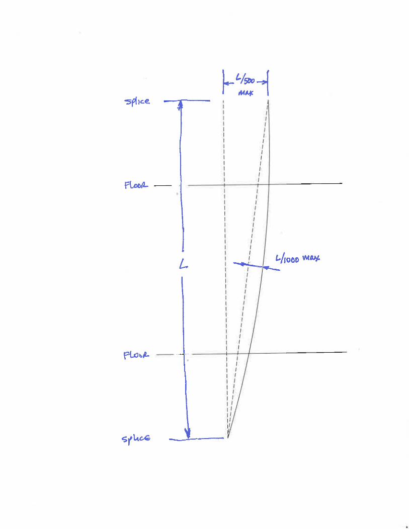
Charlie
Typewritten Text
working point
Charlie
Typewritten Text
Charlie
Typewritten Text
working point
Charlie
Typewritten Text
working line
Charlie
Line
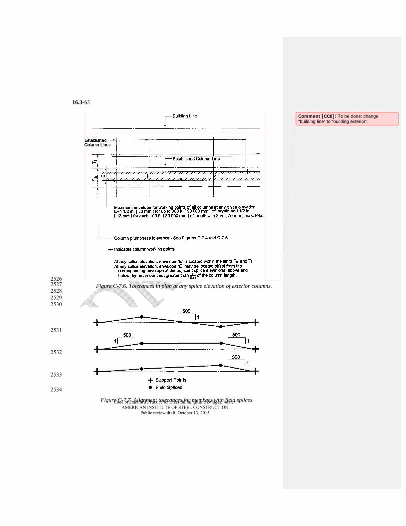
Code of Standard Practice for Steel Buildings and Bridges, <date> AMERICAN INSTITUTE OF STEEL CONSTRUCTION
Public review draft, October 13, 2015
16.3-63
2526 2527 2528
2529 2530
2531
2532
2533
2534
Figure C-7.6. Tolerances in plan at any splice elevation of exterior columns.
Figure C-7.7. Alignment tolerances for members with field splices.
Comment [CC8]: To be done: change “building line” to “building exterior”.
Code of Standard Practice for Steel Buildings and Bridges, <date> AMERICAN INSTITUTE OF STEEL CONSTRUCTION
Public review draft, October 13, 2015
16.3-64
2535 (c) For a member that consists of an individual shipping piece that does not 2536
connect to a column, the variation in elevation shall be acceptable if it is 2537 caused solely by the variations in the elevations of the supporting members 2538 within the permissible variations for the fabrication and erection of those 2539 members. 2540
(d) For a member that consists of an individual, straight shipping piece and that 2541 is a segment of a field assembled unit containing field splices between 2542 points of support, the plumbness, elevation and alignment shall be 2543 acceptable if the angular variation, vertically and horizontally, of the 2544 working line from a straight line between points of support is equal to or 2545 less than 1/500 of the distance between working points. 2546
2547 Commentary: 2548 The angular misalignment of the working line of all fabricated shipping 2549 pieces relative to the line between support points of the member as a whole 2550 in erected position must not exceed 1 in 500. Note that the tolerance is not 2551 stated in terms of a linear displacement at any point and is not to be taken as 2552 the overall length between supports divided by 500. Typical examples are 2553 shown in Figure C–7.7. Numerous conditions within tolerance for these and 2554 other cases are possible. The condition described in (d) applies to both plan 2555 and elevation tolerances. 2556
2557 (e) For a cantilevered member that consists of an individual, straight shipping 2558
piece, the plumbness, elevation and alignment shall be acceptable if the 2559 angular variation of the working line from a straight line that is extended in 2560 the plan direction from the working point at its supported end is equal to or 2561 less than 1/500 of the distance from the working point at the free end. 2562
2563 Commentary: 2564 This tolerance is evaluated after the fixed end condition is sufficient to 2565 stabilize the cantilever and before the temporary support is removed. The 2566 preset specified in the contract documents should be calculated accordingly. 2567 The temporary support cannot be used to induce artificial deflection into the 2568 cantilever to meet this tolerance after the fixed end is restrained. 2569
2570 (f) For a member of irregular shape, the plumbness, elevation and alignment 2571
shall be acceptable if the fabricated member is within its tolerances and the 2572 members that support it are within the tolerances specified in this Code. 2573
(g) For a member that is fully assembled in the field in an unstressed condition, 2574 the same tolerances shall apply as if fully assembled in the shop. 2575
(h) For a member that is field-assembled, element-by-element in place, 2576 temporary support shall be used or an alternative erection plan shall be 2577
Code of Standard Practice for Steel Buildings and Bridges, <date> AMERICAN INSTITUTE OF STEEL CONSTRUCTION
Public review draft, October 13, 2015
16.3-65
submitted to the owner’s designated representatives for design and 2578 construction. The tolerance in Section 7.13.1.2(d) shall be met in the 2579 supported condition with working points taken at the point(s) of temporary 2580 support. 2581
2582 Commentary: 2583 Trusses fabricated and erected as a unit or as an assembly of truss segments 2584 normally have excellent controls on vertical position regardless of 2585 fabrication and erection techniques. However, a truss fabricated and erected 2586 by assembling individual components in place in the field is potentially 2587 more sensitive to deflections of the individual truss components and the 2588 partially completed work during erection, particularly the chord members. 2589 In such a case, the erection process should follow an erection plan that 2590 addresses this issue. 2591
2592 7.13.1.3. For members that are identified as adjustable items by the owner’s designated 2593
representative for design in the contract documents, the fabricator shall provide 2594 adjustable connections for these members to the supporting structural steel 2595 frame. Otherwise, the fabricator is permitted to provide non-adjustable 2596 connections. When adjustable items are specified, the owner's designated 2597 representative for design shall indicate the total adjustability that is required for 2598 the proper alignment of these supports for other trades. The variation in the 2599 position and alignment of adjustable items shall be as follows: 2600
2601 (a) The variation in the vertical distance from the upper finished splice line of 2602
the nearest column to the support location specified in the structural design 2603 documents shall be equal to or less than plus or minus a in. [10 mm]. 2604
(b) The variation in the horizontal distance from the established finish line at 2605 the particular floor shall be equal to or less than plus or minus a in. [10 2606 mm]. 2607
(c) The variation in vertical and horizontal alignment at the abutting ends of 2608 adjustable items shall be equal to or less than plus or minus x in. [5 mm]. 2609
2610 Commentary: 2611 When the alignment of lintels, wall supports, curb angles, mullions and similar 2612 supporting members for the use of other trades is required to be closer than that 2613 permitted by the foregoing tolerances for structural steel, the owner's 2614 designated representative for design must identify such items in the contract 2615 documents as adjustable items. 2616
2617 7.13.2. In the design of steel structures, the owner's designated representative for 2618
design shall provide for the necessary clearances and adjustments for material 2619
Code of Standard Practice for Steel Buildings and Bridges, <date> AMERICAN INSTITUTE OF STEEL CONSTRUCTION
Public review draft, October 13, 2015
16.3-66
furnished by other trades to accommodate the mill tolerances, fabrication 2620 tolerances and erection tolerances in this Code for the structural steel frame. 2621
2622 Commentary: 2623 In spite of all efforts to minimize inaccuracies, deviations will still exist; 2624 therefore, in addition, the designs of prefabricated wall panels, partition panels, 2625 fenestrations, floor-to-ceiling door frames and similar elements must provide for 2626 clearance and details for adjustment as described in Section 7.13.2. Designs 2627 must provide for adjustment in the vertical dimension of prefabricated facade 2628 panels that are supported by the structural steel frame because the accumulation 2629 of shortening of loaded steel columns will result in the unstressed facade 2630 supported at each floor level being higher than the structural steel framing to 2631 which it must be attached. Observations in the field have shown that where a 2632 heavy facade is erected to a greater height on one side of a multistory building 2633 than on the other, the structural steel framing will be pulled out of alignment. 2634 Facades should be erected at a relatively uniform rate around the perimeter of 2635 the structure. 2636
2637 7.13.3. Prior to placing or applying any other materials, the owner's designated 2638
representative for construction shall determine that the location of the structural 2639 steel is acceptable for plumbness, elevation and alignment. The erector shall be 2640 given either timely notice of acceptance by the owner's designated 2641 representative for construction, or a listing of specific items that are to be 2642 corrected in order to obtain acceptance. Such notice shall be rendered promptly 2643 upon completion of any part of the work and prior to the start of work by other 2644 trades that may be supported, attached or applied to the structural steel frame. 2645
2646 7.14. Correction of Errors 2647
The correction of minor misfits by moderate amounts of reaming, grinding, 2648 welding or cutting, and the drawing of elements into line with drift pins, shall be 2649 considered to be normal erection operations. Errors that cannot be corrected 2650 using the foregoing means, or that require major changes in member or 2651 connection configuration, shall be promptly reported to the owner's designated 2652 representatives for design and construction and the fabricator by the erector, to 2653 enable the responsible entity to either correct the error or approve the most 2654 efficient and economical method of correction to be used by others. 2655
2656 Commentary: 2657 As used in this Section, the term “moderate” refers to the amount of reaming, 2658 grinding, welding or cutting that must be done on the project as a whole, not the 2659 amount that is required at an individual location. It is not intended to address 2660 limitations on the amount of material that is removed by reaming at an 2661 individual bolt hole, for example, which is limited by the bolt-hole size and 2662 tolerance requirements in the AISC and RCSC Specifications. 2663
Code of Standard Practice for Steel Buildings and Bridges, <date> AMERICAN INSTITUTE OF STEEL CONSTRUCTION
Public review draft, October 13, 2015
16.3-67
2664 7.15. Cuts, Alterations and Holes for Other Trades 2665
Neither the fabricator nor the erector shall cut, drill or otherwise alter their 2666 work, nor the work of other trades, to accommodate other trades, unless such 2667 work is clearly specified in the contract documents. When such work is so 2668 specified, the owner's designated representatives for design and construction 2669 shall furnish complete information as to materials, size, location and number of 2670 alterations in a timely manner so as not to delay the preparation of the approval 2671 documents. 2672
2673 7.16. Handling and Storage 2674
The erector shall take reasonable care in the proper handling and storage of the 2675 structural steel during erection operations to avoid the accumulation of excess 2676 dirt and foreign matter. The erector shall not be responsible for the removal 2677 from the structural steel of dust, dirt or other foreign matter that may 2678 accumulate during erection as the result of job-site conditions or exposure to the 2679 elements. The erector shall handle and store all bolts, nuts, washers and related 2680 fastening products in accordance with the requirements of the RCSC 2681 Specification. 2682
2683 Commentary: 2684 During storage, loading, transport, unloading and erection, blemish marks 2685 caused by slings, chains, blocking, tie-downs, etc., occur in varying degrees. 2686 Abrasions caused by handling or cartage after painting are to be expected. It 2687 must be recognized that any shop-applied coating, no matter how carefully 2688 protected, will require touching-up in the field. Touching-up of these blemished 2689 areas is the responsibility of the contractor performing the field touch-up or field 2690 painting. 2691 The erector is responsible for the proper storage and handling of 2692 fabricated structural steel at the job site during erection. Shop-painted structural 2693 steel that is stored in the field pending erection should be kept free of the ground 2694 and positioned so as to minimize the potential for water retention. The owner or 2695 owner's designated representative for construction is responsible for providing 2696 suitable job-site conditions and proper access so that the fabricator and the 2697 erector may perform their work. 2698 Job-site conditions are frequently muddy, sandy, dusty or a 2699 combination thereof during the erection period. Under such conditions it may be 2700 impossible to store and handle the structural steel in such a way as to 2701 completely avoid any accumulation of mud, dirt or sand on the surface of the 2702 structural steel, even though the fabricator and the erector manages to proceed 2703 with their work. 2704 Repairs of damage to painted surfaces and/or removal of foreign 2705 materials due to adverse job-site conditions are outside the scope of 2706

Code of Standard Practice for Steel Buildings and Bridges, <date> AMERICAN INSTITUTE OF STEEL CONSTRUCTION
Public review draft, October 13, 2015
16.3-68
responsibility of the fabricator and the erector when reasonable attempts at 2707 proper handling and storage have been made. 2708
2709 7.17. Field Painting 2710
Neither the fabricator nor the erector is responsible to paint field bolt heads and 2711 nuts or field welds, nor to touch up abrasions of the shop coat, nor to perform 2712 any other field painting. 2713
2714 7.18. Final Cleaning Up 2715
Upon the completion of erection and before final acceptance, the erector shall 2716 remove all of the erector’s falsework, rubbish and temporary buildings. 2717
2718
Code of Standard Practice for Steel Buildings and Bridges, <date> AMERICAN INSTITUTE OF STEEL CONSTRUCTION
Public review draft, October 13, 2015
16.3-69
SECTION 8. QUALITY CONTROL 2719 2720 8.1. General 2721 2722 8.1.1. The fabricator shall maintain a quality control program to ensure that the work 2723
is performed in accordance with the requirements in this Code, the AISC 2724 Specification and the contract documents. The fabricator shall have the option 2725 to use the AISC Quality Certification Program to establish and administer the 2726 quality control program. 2727
2728 Commentary: 2729 The AISC Quality Certification Program confirms to the construction industry 2730 that a certified structural steel fabrication shop has the capability by reason of 2731 commitment, personnel, organization, experience, procedures, knowledge and 2732 equipment to produce fabricated structural steel of the required quality for a 2733 given category of work. The AISC Quality Certification Program is not intended 2734 to involve inspection and/or judgment of product quality on individual projects. 2735 Neither is it intended to guarantee the quality of specific fabricated structural 2736 steel products. 2737
2738 8.1.2. The erector shall maintain a quality control program to ensure that the work is 2739
performed in accordance with the requirements in this Code, the AISC 2740 Specification and the contract documents. The erector shall be capable of 2741 performing the erection of the structural steel, and shall provide the equipment, 2742 personnel and management for the scope, magnitude and required quality of 2743 each project. The erector shall have the option to use the AISC Erector 2744 Certification Program to establish and administer the quality control program. 2745
2746 Commentary: 2747 The AISC Erector Certification Program confirms to the construction industry 2748 that a certified structural steel erector has the capability by reason of 2749 commitment, personnel, organization, experience, procedures, knowledge and 2750 equipment to erect fabricated structural steel to the required quality for a given 2751 category of work. The AISC Erector Certification Program is not intended to 2752 involve inspection and/or judgment of product quality on individual projects. 2753 Neither is it intended to guarantee the quality of specific erected structural steel 2754 products. 2755
2756 8.1.3. When the owner requires more extensive quality control procedures, or 2757
independent inspection by qualified personnel, or requires that the fabricator 2758 must be certified under the AISC Quality Certification Program and/or requires 2759 that the erector must be certified under the AISC Erector Certification Program, 2760

Code of Standard Practice for Steel Buildings and Bridges, <date> AMERICAN INSTITUTE OF STEEL CONSTRUCTION
Public review draft, October 13, 2015
16.3-70
this shall be clearly stated in the contract documents, including a definition of 2761 the scope of such inspection. 2762
2763 8.2. Inspection of Mill Material 2764
Material test reports shall constitute sufficient evidence that the mill product 2765 satisfies material order requirements. The fabricator shall make a visual 2766 inspection of material that is received from the mill, but need not perform any 2767 material tests unless the owner's designated representative for design specifies 2768 in the contract documents that additional testing is to be performed at the 2769 owner’s expense. 2770
2771 8.3. Non-Destructive Testing 2772
When non-destructive testing is required, the process, extent, technique and 2773 standards of acceptance shall be clearly specified in the contract documents. 2774
2775 8.4. Surface Preparation and Shop Painting Inspection 2776
Inspection of surface preparation and shop painting shall be planned for the 2777 acceptance of each operation as the fabricator completes it. Inspection of the 2778 paint system, including material and thickness, shall be made promptly upon 2779 completion of the paint application. When wet-film thickness is to be inspected, 2780 it shall be measured during the application. 2781
2782 8.5. Independent Inspection 2783
When inspection by personnel other than those of the fabricator and/or erector 2784 is specified in the contract documents, the requirements in Sections 8.5.1 2785 through 8.5.6 shall be met. 2786
2787 8.5.1. The fabricator and the erector shall provide the inspector with access to all 2788
places where the work is being performed. A minimum of 24 hours notification 2789 shall be given prior to the commencement of work. 2790
2791 8.5.2. Inspection of shop work by the inspector shall be performed in the fabricator’s 2792
shop to the fullest extent possible. Such inspections shall be timely, in-sequence 2793 and performed in such a manner as will not disrupt fabrication operations and 2794 will permit the repair of non-conforming work prior to any required painting 2795 while the material is still in-process in the fabrication shop. 2796
2797 8.5.3. Inspection of field work shall be promptly completed without delaying the 2798
progress or correction of the work. 2799 2800 8.5.4. Rejection of material or workmanship that is not in conformance with the 2801
contract documents shall be permitted at any time during the progress of the 2802
Code of Standard Practice for Steel Buildings and Bridges, <date> AMERICAN INSTITUTE OF STEEL CONSTRUCTION
Public review draft, October 13, 2015
16.3-71
work. However, this provision shall not relieve the owner or the inspector of the 2803 obligation for timely, in-sequence inspections. 2804
2805 8.5.5. The fabricator, erector, and owner's designated representatives for design and 2806
construction shall be informed of deficiencies that are noted by the inspector 2807 promptly after the inspection. Copies of all reports prepared by the inspector 2808 shall be promptly given to the fabricator, erector, and owner's designated 2809 representatives for design and construction. The necessary corrective work shall 2810 be performed in a timely manner. 2811
2812 8.5.6. The inspector shall not suggest, direct, or approve the fabricator or erector to 2813
deviate from the contract documents or the approved approval documents, or 2814 approve such deviation, without the written approval of the owner's designated 2815 representatives for design and construction. 2816
2817
Code of Standard Practice for Steel Buildings and Bridges, <date> AMERICAN INSTITUTE OF STEEL CONSTRUCTION
Public review draft, October 13, 2015
16.3-72
SECTION 9. CONTRACTS 2818 2819 9.1. Types of Contracts 2820 2821 9.1.1. For contracts that stipulate a lump sum price, the work that is required to be 2822
performed by the fabricator and the erector shall be completely defined in the 2823 contract documents. 2824
2825 9.1.2. For contracts that stipulate a price per pound, the scope of work that is required 2826
to be performed by the fabricator and the erector, the type of materials, the 2827 character of fabrication and the conditions of erection shall be based upon the 2828 contract documents, which shall be representative of the work to be performed. 2829
2830 9.1.3. For contracts that stipulate a price per item, the work that is required to be 2831
performed by the fabricator and the erector shall be based upon the quantity 2832 and the character of the items that are described in the contract documents. 2833
2834 9.1.4. For contracts that stipulate unit prices for various categories of structural steel, 2835
the scope of work that is required to be performed by the fabricator and the 2836 erector shall be based upon the quantity, character and complexity of the items 2837 in each category as described in the contract documents, and shall also be 2838 representative of the work to be performed in each category. 2839
2840 9.1.5. When an allowance for work is called for in the contract documents and the 2841
associated work is subsequently defined as to the quantity, complexity and 2842 timing of that work after the contract is executed, the contract price for this 2843 work shall be adjusted by change order. 2844 2845 Commentary: 2846 Allowances, if used, are not a true definition of the cost of work to be 2847 performed. By nature, an allowance is only an estimate and placeholder in the 2848 bid. Once the actual work is defined, the actual cost can be provided. It must be 2849 recognized that the actual cost can be higher or lower than the allowance. See 2850 Section 9.4. 2851 Allowances required by the contract documents or proposed by the bidder 2852 should be as thoroughly defined as practicable as to the distinct nature of the 2853 work covered by the allowance, including whether the allowance is to include 2854 materials only, fabrication costs, and/or erection costs. 2855
2856 9.2. Calculation of Weights 2857
Unless otherwise specified in the contract, for contracts stipulating a price per 2858 pound for fabricated structural steel that is delivered and/or erected, the 2859
Code of Standard Practice for Steel Buildings and Bridges, <date> AMERICAN INSTITUTE OF STEEL CONSTRUCTION
Public review draft, October 13, 2015
16.3-73
quantities of materials for payment shall be determined by the calculation of the 2860 gross weight of materials as shown in the fabrication documents. 2861 2862 Commentary: 2863 The standard procedure for calculation of weights that is described in this Code 2864 meets the need for a universally acceptable system for defining “pay weights” in 2865 contracts based upon the weight of delivered and/or erected materials. These 2866 procedures permits the owner to easily and accurately evaluate price-per-pound 2867 proposals from potential suppliers and enables all parties to a contract to have a 2868 clear and common understanding of the basis for payment. 2869
The procedure in this Code affords a simple, readily understood 2870 method of calculation that will produce pay weights that are consistent 2871 throughout the industry and that may be easily verified by the owner. While this 2872 procedure does not produce actual weights, it can be used by purchasers and 2873 suppliers to define a widely accepted basis for bidding and contracting for 2874 structural steel. However, any other system can be used as the basis for a 2875 contractual agreement. When other systems are used, both the supplier and the 2876 purchaser should clearly understand how the alternative procedure is handled. 2877
2878 9.2.1. The unit weight of steel shall be taken as 490 lb/ft3 [7 850 kg/m3]. The unit 2879
weight of other materials shall be in accordance with the manufacturer’s 2880 published data for the specific product. 2881
2882 9.2.2. The weights of standard structural shapes, plates and bars shall be calculated 2883
on the basis of fabrication documents that show the actual quantities and 2884 dimensions of material to be fabricated, as follows: 2885 2886 (a) The weights of all standard structural shapes shall be calculated using the 2887
nominal weight per ft [mass per m] and the detailed overall length. 2888 (b) The weights of plates and bars shall be calculated using the detailed overall 2889
rectangular dimensions. 2890 (c) When parts can be economically cut in multiples from material of larger 2891
dimensions, the weight shall be calculated on the basis of the theoretical 2892 rectangular dimensions of the material from which the parts are cut. 2893
(d) When parts are cut from standard structural shapes, leaving a non-standard 2894 section that is not useable on the same contract, the weight shall be 2895 calculated using the nominal weight per ft [mass per m] and the overall 2896 length of the standard structural shapes from which the parts are cut. 2897
(e) Deductions shall not be made for material that is removed for cuts, copes, 2898 clips, blocks, drilling, punching, boring, slot milling, planing or weld joint 2899 preparation. 2900
2901
Code of Standard Practice for Steel Buildings and Bridges, <date> AMERICAN INSTITUTE OF STEEL CONSTRUCTION
Public review draft, October 13, 2015
16.3-74
9.2.3. The items for which weights are shown in tables in the AISC Steel Construction 2902 Manual shall be calculated on the basis of the tabulated weights shown therein. 2903
2904 9.2.4. The weights of items that are not shown in tables in the AISC Steel 2905
Construction Manual shall be taken from the manufacturer’s catalog and the 2906 manufacturer’s shipping weight shall be used. 2907
2908 Commentary: 2909 Many items that are weighed for payment purposes are not tabulated with 2910 weights in the AISC Steel Construction Manual. These include, but are not 2911 limited to, anchor rods, clevises, turnbuckles, sleeve nuts, recessed-pin nuts, 2912 cotter pins and similar devices. 2913
2914 9.2.5. The weights of shop or field weld metal and protective coatings shall not be 2915
included in the calculated weight for the purposes of payment. 2916 2917 9.3. Revisions to the Contract Documents 2918
Revisions to the contract documents shall be confirmed by change order or extra 2919 work order. Unless otherwise noted, the issuance of a revision to the contract 2920 documents shall constitute authorization by the owner that the revision is 2921 released for construction. The contract price and schedule shall be adjusted in 2922 accordance with Sections 9.4 and 9.5. 2923
2924 9.4. Contract Price Adjustment 2925 2926 9.4.1. When the scope of work and responsibilities of the fabricator and the erector 2927
are changed from those previously established in the contract documents, an 2928 appropriate modification of the contract price shall be made. In computing the 2929 contract price adjustment, the fabricator and the erector shall consider the 2930 quantity of work that is added or deleted, the modifications in the character of 2931 the work and the timeliness of the change with respect to the status of material 2932 ordering, detailing, fabrication and erection operations. 2933
2934 Commentary: 2935 The fabrication and erection of structural steel is a dynamic process. Typically, 2936 material is being acquired at the same time that the approval documents are 2937 being prepared. Additionally, the fabrication shop will normally fabricate pieces 2938 in the order that the structural steel is being shipped and erected. 2939 Items that are revised or placed on hold generally upset these 2940 relationships and can be very disruptive to the digital modeling/detailing, 2941 fabricating and erecting processes. The provisions in Sections 3.5, 4.4.2 and 9.3 2942 are intended to minimize these disruptions so as to allow work to continue. 2943

Code of Standard Practice for Steel Buildings and Bridges, <date> AMERICAN INSTITUTE OF STEEL CONSTRUCTION
Public review draft, October 13, 2015
16.3-75
Accordingly, it is required in this Code that the reviewer of requests for contract 2944 price adjustments recognize this and allow compensation to the fabricator and 2945 the erector for these inefficiencies and for the materials that are purchased and 2946 the detailing, fabrication and erection that has been performed, when affected by 2947 the change. 2948
2949 9.4.2. Requests for contract price adjustments shall be presented by the fabricator 2950
and/or the erector in a timely manner and shall be accompanied by a description 2951 of the change that is sufficient to permit evaluation and timely approval by the 2952 owner. 2953
2954 9.4.3. Price-per-pound and price-per-item contracts shall provide for additions or 2955
deletions to the quantity of work that are made prior to the time the work is 2956 released for construction. When changes are made to the character of the work 2957 at any time, or when additions and/or deletions are made to the quantity of the 2958 work after it is released for detailing, fabrication or erection, the contract price 2959 shall be equitably adjusted. 2960
2961 9.5. Scheduling 2962 2963 9.5.1. The contract schedule shall state when the design documents will be released 2964
for construction, if the design documents are not available at the time of 2965 bidding, and when the job site, foundations, piers and abutments will be ready, 2966 free from obstructions and accessible to the erector, so that erection can start at 2967 the designated time and continue without interference or delay caused by the 2968 owner's designated representative for construction or other trades. 2969
2970 9.5.2. The fabricator and the erector shall advise the owner's designated 2971
representatives for design and construction, in a timely manner, of the effect 2972 any revision has on the contract schedule. 2973
2974 9.5.3. If the fabrication or erection is significantly delayed due to revisions to the 2975
requirements of the contract, or for other reasons that are the responsibility of 2976 others, the fabricator and/or erector shall be compensated for the additional 2977 costs incurred. 2978
2979 9.6. Terms of Payment 2980
The fabricator shall be paid for mill materials and fabricated product that is 2981 stored off the job site. Other terms of payment for the contract shall be outlined 2982 in the contract documents. 2983 2984 Commentary: 2985

Code of Standard Practice for Steel Buildings and Bridges, <date> AMERICAN INSTITUTE OF STEEL CONSTRUCTION
Public review draft, October 13, 2015
16.3-76
These terms include such items as progress payments for material, fabrication, 2986 erection, retainage, performance and payment bonds and final payment. If a 2987 performance or payment bond, paid for by the owner, is required by contract, no 2988 retainage shall be required. 2989
2990
Code of Standard Practice for Steel Buildings and Bridges, <date> AMERICAN INSTITUTE OF STEEL CONSTRUCTION
Public review draft, October 13, 2015
16.3-77
SECTION 10. ARCHITECTURALLY EXPOSED STRUCTURAL STEEL 2991 2992 10.1. General Requirements 2993
When members are specifically designated as architecturally exposed structural 2994 steel or AESS in the contract documents, the requirements in Sections 1 through 2995 9 shall apply as modified in Section 10. Surfaces exposed to view of AESS 2996 members and components shall be fabricated and erected with the care and 2997 dimensional tolerances that are stipulated in Sections 10.2 through 10.5. 2998 2999 Commentary: 3000 The designation of steel as AESS adds cost, and that cost is higher as the level of 3001 the AESS designation increases. However, not all exposed steel must be 3002 designated as AESS. There are many applications in which the as-produced 3003 appearance of fabricated and erected structural steel may be deemed sufficient 3004 without any special additional work. 3005 3006
10.1.1. The following categories shall be used when referring to AESS: 3007 3008
AESS 1: basic elements. 3009 AESS 2: feature elements viewed at a distance greater than 20 ft (6 m). 3010 AESS 3: feature elements viewed at a distance less than 20 ft (6 m). 3011 AESS 4: showcase elements with special surface and edge treatment beyond 3012
fabrication. 3013 AESS C: custom elements with characteristics described in the contract 3014
documents. 3015 3016
Commentary: 3017 The categories are listed in the AESS matrix shown in Table 10.1. Each category 3018 describes characteristics with successively more detailed – and costly – 3019 requirements. 3020 3021 Basic elements in AESS 1 are those that have workmanship requirements 3022
that exceed what would be done in non-AESS construction. 3023 Feature elements in AESS 2 and 3 exceed the basic requirements, but the 3024
intent is to allow the viewer to see the art of metalworking. AESS 2 is 3025 achieved primarily through geometry without finish work, and treats things 3026 that can be seen at a larger viewing distance, like enhanced treatment of 3027 bolts, welds, connection and fabrication details, and tolerances for gaps, 3028 copes and similar details. AESS 3 is achieved through geometry and basic 3029 finish work, and treats things that can be seen at a closer viewing distance 3030 or are subject to touch by the viewer, with welds that are generally smooth 3031
Code of Standard Practice for Steel Buildings and Bridges, <date> AMERICAN INSTITUTE OF STEEL CONSTRUCTION
Public review draft, October 13, 2015
16.3-78
but visible. AESS 3 involves the use of a mock-up and acceptance is based 3032 upon the approved conditions of the mock-up. 3033
Showcase elements in AESS 4 are those for which the designer intends that 3034 the form is the only feature showing in an element. All welds are ground 3035 and filled, edges are ground square and true. All surfaces are filled and 3036 sanded to a smoothness that doesn’t catch on a cloth or glove. Tolerances of 3037 fabricated forms are more stringent – generally half of standard tolerance. 3038 AESS 4 involves the use of a mock-up and acceptance is based upon the 3039 approved conditions of the mock-up. 3040
Custom elements in AESS C are those with other requirements defined in 3041 the contract documents. 3042
3043 10.1.2. A mock-up shall be required for AESS 3, 4, and C. If a mock-up is to be used in 3044
other AESS categories, it shall be specified in the contract documents. When 3045 required, the nature and extent of the mock-up shall be specified in the contract 3046 documents. Alternatively, when a mock-up is not practical, the first piece of an 3047 element or connection can be used to determine acceptability. 3048
3049 Commentary: 3050 Generally, a mock-up is produced and approved in the shop and subsequently 3051 placed in the field. The acceptability of the mock-up can be affected by many 3052 factors, including distance of view, lighting, and finishing. The expectations for 3053 the location and conditions of the mock-up at time of approval should be 3054 defined in the contract documents. 3055
3056 10.2. Contract Documents 3057
The following additional information shall be provided in the contract 3058 documents when AESS is specified: 3059
3060 a. Specific identification of members or components that are AESS using the 3061
AESS Categories listed in Section 10.1.2 and Table 10.1; 3062 b. Fabrication and/or erection tolerances that are to be more restrictive than 3063
provided for in this Appendix, if any; 3064 b. For Category AESS C, the AESS matrix included in Table 10.1 shall be 3065
used to specify the required treatment of the element. 3066 c. Any variations from the AESS characteristics of Table 10.1. 3067 d. Any other special requirements for AESS members and components, such as 3068
the orientation of HSS weld seams and bolt heads. 3069 3070 10.3. Approval Documents 3071
All members designated as AESS shall be clearly identified to a Category, either 3072 AESS 1, 2, 3, 4 or C, in the approval documents. Tack welds, temporary braces, 3073
Code of Standard Practice for Steel Buildings and Bridges, <date> AMERICAN INSTITUTE OF STEEL CONSTRUCTION
Public review draft, October 13, 2015
16.3-79
backing bars, and fixtures used in fabrication of AESS shall be shown in the 3074 fabrication documents. Architecturally sensitive connection details shall be 3075 submitted for approval by the owner’s designated representative for design 3076 prior to completion of the approval documents. 3077
3078 Commentary: 3079 Variations, if any, from the AESS Categories listed must be clearly noted. These 3080 variations could include machined surfaces, locally abraded surfaces, and 3081 forgings. In addition, if distinction is to be made between different surfaces or 3082 parts of members the transition line/plane must be clearly identified/defined on 3083 the approval documents. 3084
3085 10.4. Fabrication 3086 3087 10.4.1. The fabricator shall handle the steel with care to avoid marking or distorting the 3088
steel members: 3089 3090
(a) Slings shall be nylon type or chains or wire rope with softeners. 3091 (b) Care shall be taken to minimized damage to any shop paint or coating. 3092 (c) When temporary braces or fixtures are required during fabrication or 3093
shipment, or to facilitate erection, care shall be taken to avoid blemishes or 3094 unsightly surfaces resulting from the use or removal of such temporary 3095 elements. 3096
(d) Tack welds not incorporated into final welds shall be treated consistently 3097 with requirements for final welds. 3098
3099 10.4.2. Members fabricated of unfinished, reused, galvanized, or weathering steel that 3100
are to be AESS may still have erection marks, painted marks or other marks on 3101 surfaces in the completed structure. Special requirements, if any, shall be 3102 specified as Category AESS C. 3103
3104 10.4.3. The permissible tolerances for member depth, width, out of square, and camber 3105
and sweep shall be as specified in ASTM A6 and ASTM A500. The following 3106 exceptions apply: 3107
3108 (a) For Categories AESS 3 and 4, the matching of abutting cross-sections shall 3109
be required. 3110 (b) For Categories AESS 2, 3 and 4, the as-fabricated straightness tolerance 3111
shall be one-half of that specified in ASTM A6 and ASTM A500. 3112 3113 10.4.4. For curved structural members, whether composed of a single standard 3114
structural shape or built-up, the as-fabricated variation from the theoretical 3115

Code of Standard Practice for Steel Buildings and Bridges, <date> AMERICAN INSTITUTE OF STEEL CONSTRUCTION
Public review draft, October 13, 2015
16.3-80
curvature shall be equal to or less than the standard camber and sweep 3116 tolerances permitted for straight members in the applicable ASTM standard. 3117
3118 Commentary: 3119 The curvature tolerance for curved AESS members is not reduced from that used 3120 for curved non-AESS members because curved members have no straight line to 3121 sight and the resulting deviations are therefore indistinguishable. See also the 3122 Commentary to Section 6.4.2. 3123
3124 10.4.5. The tolerance on overall profile dimensions of welded built-up members shall 3125
meet the requirements in AWS D1.1. For Categories AESS 2, 3 and 4, the as-3126 fabricated straightness tolerance for the member as a whole shall be one-half of 3127 that specified in AWS D1.1. 3128
3129 10.4.6. For Categories AESS 3 and 4, copes, miters and cuts in surfaces exposed to 3130
view shall have a gap that is uniform within 1/16 in. (2 mm), if shown to be an 3131 open joint. If instead the joint is shown to be in contact, the contact shall be 3132 uniform within 1/16 in. (2 mm). 3133
3134 10.4.7. For Categories AESS 1, 2 and 3, the surface condition of steel given in ASTM 3135
A6 shall be acceptable. For Category AESS 4, surface imperfections shall be 3136 filled and sanded to meet the acceptance criteria established with the mock-up 3137 required in Section 10.1.2. 3138
3139 10.4.8. For Categories AESS 1, 2 and 3, welds shall meet AWS D1.1 requirements, 3140
except that weld spatter exposed to view, if any, shall be removed. For Category 3141 AESS 4, welds shall be contoured and blended, and spatter exposed to view, if 3142 any, shall be removed. 3143
3144 10.4.9. For Categories AESS 1 and 2, weld projection up to 1/16 in. (2 mm) is 3145
acceptable for butt and plug welded joints. For Categories AESS 3 and 4, welds 3146 shall be ground smooth/filled. 3147
3148 10.4.10. For Categories AESS 1, 2 and 3, weld show-through shall be acceptable as 3149
produced. For Category AESS 4, the fabricator shall minimize the weld show-3150 through. 3151
3152 Commentary: 3153 Weld show-through is a visual indication of the presence of a weld or welds on 3154 the opposite surface from the viewer. It is a function of weld size and material 3155 thickness and can’t be eliminated in thin material with thick welds. When weld 3156 show-through is a concern, this should be addressed in the mock-up. 3157
3158

Code of Standard Practice for Steel Buildings and Bridges, <date> AMERICAN INSTITUTE OF STEEL CONSTRUCTION
Public review draft, October 13, 2015
16.3-81
10.4.11. AESS shall be prepared to meet the requirement of SSPC-SP 6. Prior to blast 3159 cleaning: 3160
3161 (a) Grease or oil, if any is present, shall be removed by solvent cleaning to 3162
meet the requirements of SSPC-SP 1. 3163 (b) Weld spatter, slivers, and similar surface discontinuities shall be removed. 3164 (c) Sharp corners resulting from shearing, flame cutting, or grinding shall be 3165
eased. 3166 3167 10.4.12. For Categories AESS 1 and 2, seams of hollow structural sections shall be 3168
acceptable as produced. For Category AESS 3, seams shall be oriented as 3169 specified in the contract documents. For Category AESS 4, seams shall be 3170 treated so they are not apparent. 3171
3172 10.5. Delivery of Materials 3173 The fabricator shall use special care to avoid bending, twisting or otherwise distorting 3174 AESS. All tie downs on loads shall be nylon straps or chains with softeners to avoid 3175 damage to edges and surfaces of members. The standard for acceptance of delivered and 3176 erected members shall be equivalent to the standard employed at fabrication. 3177 3178 10.6. Erection 3179 The erector shall use special care in unloading, handling and erecting AESS to avoid 3180 marking or distorting the AESS. The erector shall plan and execute all operations in such 3181 a manner that allows the architectural appearance of the structure to be maintained: 3182 3183 (a) Slings shall be nylon type or chains or wire rope with softeners. 3184 (b) Care shall be taken to minimize damage to any shop paint or coating. 3185 (c) When temporary braces or fixtures are required to facilitate erection, care shall be 3186
taken to avoid any blemishes, holes or unsightly surfaces resulting from the use or 3187 removal of such temporary elements. 3188
(d) Tack welds not incorporated into final welds shall be ground smooth. 3189 (e) All backing bars shall be removed and ground smooth. 3190 (f) All bolt heads in connections shall be on the same side, as specified, and consistent 3191
from one connection to another. 3192 (g) For Category AESS 4, open holes shall be filled with weld metal or body filler and 3193
smoothed by grinding or filling to the standards applicable to the shop fabrication of 3194 the materials. 3195 3196 3197
<<Table 10-1 here; editorially updated to match foregoing provisions>> 3198 3199 3200
3201

DR
AFT
FO
R 1
2/9/
14 C
OD
E C
OM
MIT
TEE
MEE
TIN
G
PA
GE
5
Tabl
e 1
– A
ES
S C
ate
gor
y M
atri
x
Cat
egor
y
AES
S C
A
ESS
4 A
ESS
3 A
ESS
2 A
ESS
1 SS
S
Cus
tom
E
lem
ents
S
how
case
E
lem
ents
Fe
atur
e E
lem
ents
Fe
atur
e E
lem
ents
B
asic
E
lem
ents
S
tand
ard
Stru
ctur
al
Ste
el
Id
Cha
ract
eris
tics
Vie
wed
at a
D
ista
nce ≤
6 m
V
iew
ed a
t a
Dis
tanc
e >
6 m
CS
A S
16
1.1
Sur
face
pre
para
tion
to S
SP
C-S
P 6
√
√ √
√
1.2
Sha
rp e
dge
s g
roun
d sm
oot
h
√
√ √
√
1.3
Co
ntin
uous
wel
d ap
pea
ranc
e
√
√ √
√
1.4
Sta
nda
rd s
truc
tura
l bol
ts, o
rient
ed a
s sp
ecifi
ed
√ √
√ √
1.
5 W
eld
spat
ters
rem
oved
√
√ √
√
2.
1 V
isu
al S
am
ples
op
tiona
l op
tiona
l op
tion
al
2.2
One
-hal
f sta
ndar
d fa
bric
atio
n to
lera
nce
s
√
√ √
2.3
Fab
ricat
ion
mar
ks n
ot a
ppar
ent
√ √
√
2.
4 W
elds
uni
form
an
d sm
ooth
√
√ √
3.
1 M
ill m
arks
rem
oved
√
√
3.2
But
t and
plu
g w
eld
s g
roun
d sm
ooth
and
fille
d
√
√
3.3
HS
S w
eld
seam
orie
nte
d fo
r re
duc
ed v
isib
ility
√
√
3.4
Cro
ss s
ectio
nal a
butti
ng
surf
ace
alig
ned
√ √
3.
5 Jo
int g
ap to
lera
nces
min
imiz
ed
√ √
3.
6 A
ll w
elde
d c
onn
ectio
ns
optio
nal
optio
nal
4.1
HS
S s
eam
no
t ap
pare
nt
√
4.
2 W
elds
con
tour
ed a
nd b
lend
ed
√
4.
3 S
urfa
ces
fille
d an
d sa
nde
d
√
4.4
Wel
d sh
ow-t
hro
ugh
min
imiz
ed
√
C.1
C
.2
C
.3
C
.4
C
.5
[CC
1]
Attachment C
134

DR
AFT
FO
R 1
2/9/
14 C
OD
E C
OM
MIT
TEE
MEE
TIN
G
PA
GE
7
N
otes
1.
1 P
rior
to b
last
cle
anin
g, a
ny
depo
sits
of g
reas
e or
oil
are
to b
e re
mo
ved
by
solv
ent
cle
ani
ng,
SS
PC
-SP
1.
1.2
Rou
gh s
urfa
ces
are
to b
e de
bur
red
and
gro
und
sm
ooth
. Sh
arp
ed
ges
resu
lting
fro
m f
lam
e cu
ttin
g, g
rindi
ng a
nd
esp
ecia
lly s
hear
ing
are
to b
e s
ofte
ned
.
1.3
Inte
rmitt
ent
we
lds
are
mad
e c
ontin
uou
s, e
ither
with
ad
ditio
nal
wel
ding
, cau
lkin
g o
r bo
dy
fille
r. F
or c
orro
sive
en
viro
nm
ent
s, a
ll jo
ints
sho
uld
be
sea
l we
lded
. Sea
ms
of h
ollo
w s
truc
tura
l sec
tions
sha
ll be
acc
ept
able
as
prod
uce
d.
1.4
All
bolt
hea
ds in
con
nect
ions
sha
ll be
on
the
sam
e si
de,
as
spec
ified
, an
d co
nsis
tent
fro
m o
ne c
onne
ctio
n to
ano
ther
. 1.
5 W
eld
spat
ter,
sliv
ers,
sur
face
dis
cont
inu
ities
are
to b
e r
em
ove
d. W
eld
proj
ectio
n u
p to
2 m
m is
acc
epta
ble
for
butt
and
pl
ug
we
lde
d jo
ints
.
2.
1 V
isua
l sa
mpl
es a
re e
ither
a 3
-D r
end
erin
g, a
ph
ysic
al s
amp
le, a
firs
t off
insp
ectio
n, a
sca
led
moc
k-up
or
a fu
ll-sc
ale
moc
k-up
, as
spec
ifie
d in
Co
ntra
ct D
ocum
ent
s.
2.2
The
se to
lera
nces
are
req
uire
d to
be
one
-hal
f of
thos
e o
f sta
ndar
d st
ruct
ura
l ste
el a
s sp
ecifi
ed
in C
SA
S1
6.
2.3
Me
mbe
rs m
arke
d w
ith s
peci
fic n
umbe
rs d
urin
g th
e fa
bric
atio
n an
d e
rect
ion
pro
cess
es a
re n
ot t
o b
e v
isib
le.
3.1
All
mill
mar
ks a
re n
ot t
o b
e v
isib
le in
the
finis
hed
pro
duct
.
3.2
Cau
lkin
g o
r bo
dy
fille
r is
acc
epta
ble.
3.
3 S
eam
s sh
all
be
orie
nted
aw
ay
fro
m v
iew
or
as in
dic
ate
d in
the
Con
tra
ct D
ocum
ent
s.
3.4
The
mat
chin
g of
abu
ttin
g cr
oss
-sec
tion
s sh
all b
e re
quire
d.
3.5
Thi
s ch
ara
cter
istic
is s
imila
r to
2.2
abo
ve.
A c
lear
dis
tanc
e be
twe
en a
butti
ng m
em
ber
s of
3 m
m is
req
uire
d.
3.6
Hid
den
bo
lts m
ay
be
con
side
red
.
4.
1 H
SS
sea
ms
shal
l be
tre
ated
so
the
y ar
e n
ot a
ppar
en
t.
4.2
In a
dditi
on to
a c
onto
ure
d an
d b
len
ded
app
ear
ance
, w
eld
ed tr
ansi
tions
be
twe
en
me
mbe
rs a
re a
lso
requ
ired
to b
e
con
tou
red
and
ble
nde
d.
4.3
The
ste
el s
urf
ace
impe
rfec
tion
s sh
ould
be
fille
d a
nd
san
ded
. 4.
4 T
he b
ackf
ace
of t
he w
eld
ed e
lem
ent
ca
used
by
the
wel
ding
pro
cess
can
be
min
imiz
ed b
y h
and
grin
din
g th
e b
acks
ide
of
the
wel
d. T
he
deg
ree
of
we
ld-t
hro
ugh
is a
fu
nctio
n o
f w
eld
siz
e an
d m
ate
rial.
C.
Add
ition
al c
hara
cte
ristic
s m
ay
be
add
ed fo
r cu
stom
ele
men
ts.
Attachment C
136

Code of Standard Practice for Steel Buildings and Bridges, <date> AMERICAN INSTITUTE OF STEEL CONSTRUCTION
Public review draft, October 13, 2015
16.3-82
3202 3203

Code of Standard Practice for Steel Buildings and Bridges, <date> AMERICAN INSTITUTE OF STEEL CONSTRUCTION
Public review draft, October 13, 2015
16.3-83
3204

Code of Standard Practice for Steel Buildings and Bridges, <date> AMERICAN INSTITUTE OF STEEL CONSTRUCTION
Public review draft, October 13, 2015
16.3-84
3205
AMERICAN INSTITUTE OF STEEL CONSTRUCTION One East Wacker Drive, Suite 700, Chicago, Illinois 60601 AISC 303-10 (2M710) Comment [CC9]: Update.