Code of practice for strengthened/reinforced soils
112
raising standards worldwide ™ NO COPYING WITHOUT BSI PERMISSION EXCEPT AS PERMITTED BY COPYRIGHT LAW BSI Standards Publication BS 8006-2:2011 Code of practice for strengthened/reinforced soils Part 2: Soil nail design Licensed copy: University of Brimingham, University of Birmingham, Version correct as of 18/02/2012 14:05, (c) The British Standards Institution 2012
Transcript of Code of practice for strengthened/reinforced soils

raising standards worldwide™
NO COPYING WITHOUT BSI PERMISSION EXCEPT AS PERMITTED BY COPYRIGHT LAW
BSI Standards Publication
BS 8006-2:2011
Code of practice forstrengthened/reinforcedsoilsPart 2: Soil nail design
Lice
nsed
cop
y: U
nive
rsity
of B
rimin
gham
, Uni
vers
ity o
f Birm
ingh
am, V
ersi
on c
orre
ct a
s of
18/
02/2
012
14:0
5, (
c) T
he B
ritis
h S
tand
ards
Inst
itutio
n 20
12

Publishing and copyright information
The BSI copyright notice displayed in this document indicates when the documentwas last issued.
© BSI 2011
ISBN 978 0 580 58338 4
ICS 93.020
The following BSI references relate to the work on this standard:Committee reference B/526/4Draft for comment 11/30161659 DC
Publication history
First published (as BS 8006), November 1995Revised as BS 8006-1, October 2010 and BS 8006-2 (this standard), December 2011
Amendments issued since publication
Date Text affected
BS 8006-2:2011 BRITISH STANDARD
Lice
nsed
cop
y: U
nive
rsity
of B
rimin
gham
, Uni
vers
ity o
f Birm
ingh
am, V
ersi
on c
orre
ct a
s of
18/
02/2
012
14:0
5, (
c) T
he B
ritis
h S
tand
ards
Inst
itutio
n 20
12

ContentsForeword iv
Section 1 : General 11.1 Scope 11.2 Normative references 11.3 Terms, definitions and symbols 2
Section 2 : Soil nailing applications and construction considerations 82.1 General 82.2 Description of typical soil nail element components 82.3 Typical applications 92.4 Construction design considerations 12
Section 3 : Suitability of ground and groundwater conditions 183.1 General 183.2 Understanding the site geology 183.3 General requirements for suitability of soils and rocks for soil nailing 193.4 Suitability of cohesive soils for soil nailing 193.5 Suitability of granular soils for soil nailing 243.6 Suitability of weak rocks for soil nailing 253.7 Suitability of fill for soil nailing 263.8 Effects of groundwater on soil nailing 293.9 Effects of underlying geological features on soil nailing 313.10 Site investigation 323.11 Soil-nailing related site investigation – Field trials 333.12 Soil-nailing related site investigation – Chemical testing 333.13 Preliminary assessment of degradation risk 333.14 Detailed assessment of degradation risk for buried components 353.15 Detailed assessment of degradation risk for exposed components and
surfaces 35
Section 4 : Basis for design 374.1 Design method 374.2 Analysis of stability 434.3 Soil nail pullout resistance 514.4 Numerical analysis 604.5 Soil nail element design 614.6 Influence of durability and degradation on the choice of nail tendon 614.7 Design of facing 734.8 Drainage 86
Section 5 : Serviceability and movements 895.1 Serviceability limit state 895.2 Serviceability limit state analysis 905.3 Estimation of movement – General 905.4 Use of empirical relationships 905.5 Numerical modelling 925.6 Case studies 92
Section 6 : Design verification 936.1 Testing 936.2 Nail pullout resistance 956.3 Materials testing 1006.4 Other tests 1006.5 Monitoring 1006.6 Monitoring during construction 1006.7 Long-term or post-construction monitoring 100
Section 7 : Maintenance 101
Bibliography 102
BRITISH STANDARD BS 8006-2:2011
© BSI 2011 • i
Lice
nsed
cop
y: U
nive
rsity
of B
rimin
gham
, Uni
vers
ity o
f Birm
ingh
am, V
ersi
on c
orre
ct a
s of
18/
02/2
012
14:0
5, (
c) T
he B
ritis
h S
tand
ards
Inst
itutio
n 20
12

List of figuresFigure 1 – Terms used in this standard 2Figure 2 – Possible components of soil nail system, pre-bored and grouted,shown with rigid facing 9Figure 3 – Typical soil nailing applications (new cut and vertical cutting) 10Figure 4 – Soil nail placement to preserve existing vegetation 10Figure 5 – Example of soil nailing of an existing retaining structure 11Figure 6 – Example of soil nailing of an embankment 12Figure 7 – Bulk excavation and requirement to check overall stability 14Figure 8 – Excavation tolerances 14Figure 9 – Examples of the effect of pre-existing shear surfaces on soil-nailedstructures 22Figure 10 – Problems caused by granular material in glacial till 23Figure 11 – Adverse effects of jointing and bedding on cut slopes in weak orweathered rock 26Figure 12 – Effect of groundwater on wall facing 31Figure 13 – Typical dimensions of soil nailing applications based on slopeangle 38Figure 14 – Relevant modes of ultimate and serviceability limit states 40Figure 15 – Geometry and dimensions of a soil nailed slope 41Figure 16 – Ultimate limit state modes of failure 44Figure 17 – Slip circle method of slices 45Figure 18 – Methods of resolving nail force and degree of conservatism 47Figure 19 – Two-part wedge 49Figure 20 – Mobilization of bond stress as a function of relative soil-nailmovement 52Figure 21 – Limiting nail strength envelope 52Figure 22 – Effect of far field stress on mobilized bond stress 54Figure 23 – Modification of interface stresses due to far field stress changes 55Figure 24 – Relationships between radial friction normalized by vertical effectivestress for a range of characteristic friction angle 55Figure 25 – Modification of local interface stresses due to nail installationeffects 56Figure 26 – Effect of test length and axial stiffness on measured averagebond 57Figure 27 – A 25 mm diameter steel tendon with a 40 mm diameterimpermeable duct 69Figure 28 – A centralizer to provide cover to a coated nail to reduce the risk ofdamage to the coating during installation 70Figure 29 – A stainless steel self-drilling tendon complete with drill bit, hollowtendon, coupler and head plate 70Figure 30 – Calculation of required nail plate size for a given design nailforce 79Figure 31 – Calculation of design loading acting on the rear of hard facing 80Figure 32 – Calculation of design loading acting on a simple flexible facing 82Figure 33 – Calculation of tension and deformation in flexible facing for a givendesign loading 83Figure 34 – Requirements of a complex flexible facing 85Figure 35 – Typical types of drainage for soil nailing 86Figure 36 – Typical surface water interceptor detail above a steep soil-nailedslope 87Figure 37 – Example of a raking drain in a steep soil-nailed slope 87Figure 38 – Typical detail for a weep hole in a steep soil-nailed wall 88Figure 39 – Schematic layout of the nail load test system 98
BRITISH STANDARDBS 8006-2:2011
ii • © BSI 2011
Lice
nsed
cop
y: U
nive
rsity
of B
rimin
gham
, Uni
vers
ity o
f Birm
ingh
am, V
ersi
on c
orre
ct a
s of
18/
02/2
012
14:0
5, (
c) T
he B
ritis
h S
tand
ards
Inst
itutio
n 20
12

List of tablesTable 1 – Summary of ground conditions best suited and less well suited to soilnailing 21Table 2 – Principal types and suitability for soil nailing of non-engineered fill 29Table 3 – Typical corrosion rates for uncoated steel in undisturbed groundconditions 35Table 4 – Classification of surfaces exposed to the atmospheric environment 36Table 5 – Partial factors for soil nail design 43Table 6 – Ultimate limit state approach to deriving design values 60Table 7 – Types of stainless steel 64Table 8 – Types of glass fibre (after Littlejohn [30]) 65Table 9 – Summary of recommendations for different soil nailing systems inrelation to different categories of risk 73Table 10 – Displacements at the top of steep soil nailed structures 91Table 11 – Type of soil nail test (from BS EN 14490:2010) 94Table 12 – Recommended test frequency (from BS EN 14490:2010) 95Table 13 – Criteria for static loading of soil nails 97Table 14 – Values of correlation factor ξ 99
Summary of pages
This document comprises a front cover, an inside front cover, pages i to iv,pages 1 to 104, an inside back cover and a back cover.
BRITISH STANDARD BS 8006-2:2011
© BSI 2011 • iii
Lice
nsed
cop
y: U
nive
rsity
of B
rimin
gham
, Uni
vers
ity o
f Birm
ingh
am, V
ersi
on c
orre
ct a
s of
18/
02/2
012
14:0
5, (
c) T
he B
ritis
h S
tand
ards
Inst
itutio
n 20
12

ForewordPublishing information
This part of BS 8006 is published by BSI and came into effect on31 December 2011. It was prepared by Subcommittee B/526/4, Strengthened/reinforced soils and other fills, under the authority of Technical Committee B/526, Geotechnics. A list of organizations represented on this committee can be obtained on request to its secretary.
Together with BS 8006-1:2010, this part of BS 8006 supersedes BS 8006:1995, which is withdrawn.
Relationship with other publications
This standard is published in two parts:
• Code of practice for strengthened/reinforced soils and other fills
• Code of practice for strengthened/reinforced soils – Part 2: Soil nailing
This part has been drafted following the principles of BS EN 1997-1:2004.
Information about this document
This part of BS 8006 was drafted to meet the specific needs of designers andinstallers of soil nails for strengthening and/or reinforcing soil slopes.
Use of this document
As a code of practice, this part of BS 8006 takes the form of guidance andrecommendations. It should not be quoted as if it were a specification andparticular care should be taken to ensure that claims of compliance are notmisleading.
Any user claiming compliance with this part of BS 8006 is expected to be able tojustify any course of action that deviates from its recommendations.
It has been assumed in the preparation of this British Standard that theexecution of its provisions will be entrusted to appropriately qualified andexperienced people, for whose use it has been produced.
The recommendations in this British Standard are based on typical UK practiceand therefore might not be wholly valid in other territorial or regionalenvironments. Design checks in accordance with other British or internationalStandards might be necessary.
This standard is likely to be used under a variety of contractual arrangementsand forms of contract. In many cases multiple designers might be involved.Therefore, irrespective of the contract form it is essential that the design of thesoil nailing element of a project is properly integrated into whole scheme andcontractual interfaces are clearly and appropriately specified within contractdocuments.
Presentational conventions
The provisions in this standard are presented in roman (i.e. upright) type. Itsrecommendations are expressed in sentences in which the principal auxiliaryverb is “should”.
Commentary, explanation and general informative material is presented insmaller italic type, and does not constitute a normative element.
Contractual and legal considerations
This publication does not purport to include all the necessary provisions of acontract. Users are responsible for its correct application.
Compliance with a British Standard cannot confer immunity from legalobligations.
BRITISH STANDARDBS 8006-2:2011
iv • © BSI 2011
Lice
nsed
cop
y: U
nive
rsity
of B
rimin
gham
, Uni
vers
ity o
f Birm
ingh
am, V
ersi
on c
orre
ct a
s of
18/
02/2
012
14:0
5, (
c) T
he B
ritis
h S
tand
ards
Inst
itutio
n 20
12

Section 1 : General
1.1 ScopeThis part of BS 8006 gives recommendations and guidance for stabilizing soilslopes and faces using soil nails. Other methods of stabilization using reinforcedsoil methods are given in BS 8006-1:2010 and both parts might be needed forcomplex structures.
Additional considerations might be required for unusually loaded or high soilnailed slopes, or where they interface with other structures.
Whilst BS EN 1997-1:2004 specifically excludes soil nailing, this standard isintended to harmonize the design approach of soil nailing with othergeotechnical structures designed using BS EN 1997-1:2004.
The principal purpose of this standard is to provide design guidance, however,where knowledge of construction methodology is required for design purposesthen appropriate paragraphs have been included. Construction guidance is givenin execution standard BS EN 14490:2010. At the time of preparation of thisstandard, CEN Technical Committee TC341 is drafting a standard covering thetesting of soil nails.
Structures and processes that are similar to soil nailing but not addressed in thestandard are described in 2.3.6.
1.2 Normative referencesThe following referenced documents are indispensable for the application ofthis document. For dated references, only the edition cited applies. For undatedreferences, the latest edition of the referenced document (including anyamendments) applies.
BS 8006-1:2010, Code of practice for strengthened/reinforced soils and otherfills – Part 1: General
BS 8081, Code of practice for ground anchorages
BS EN 196 (all parts), Methods of testing concrete
BS EN 197-1:2000, Cement – Part 1: Composition, specifications and conformitycriteria for common cements
BS EN 206-1, Concrete – Part 1: Specification, performance, production andconformity
BS EN 1537, Execution of special geotechnical work– Ground anchors
BS EN 1990, Eurocode – Basis of structural design
BS EN 1992-1-1, Eurocode 2 – Design of concrete structures – Part 1-1: Generalrules and rules for buildings
BS EN 1997-1:2004, Eurocode 7 – Geotechnical design – Part 1: General rules
BS EN 1997-2, Eurocode 7 – Geotechnical design – Part 2: Ground investigationand testing
BS EN 10080, Steel for the reinforcement of concrete – Weldable reinforcingsteel – General
BS EN 14487 (both parts), Sprayed concrete
BS EN 14490:2010, Execution of special geotechnical works – Soil nailing
BRITISH STANDARD BS 8006-2:2011
© BSI 2011 • 1
Lice
nsed
cop
y: U
nive
rsity
of B
rimin
gham
, Uni
vers
ity o
f Birm
ingh
am, V
ersi
on c
orre
ct a
s of
18/
02/2
012
14:0
5, (
c) T
he B
ritis
h S
tand
ards
Inst
itutio
n 20
12

BS EN ISO 14688 (both parts), Geotechnical investigation and testing –Identification and classification of soil
BS EN ISO 14689-1, Geotechnical investigation and testing – Identification andclassification of rock – Part 1: Identification and description
BS EN ISO 22475-1, Geotechnical investigation and testing – Sampling methodsand groundwater measurements – Part 1: Technical principles for execution
BS EN ISO 22476 (all parts), Geotechnical investigation and testing – Field testing
1.3 Terms, definitions and symbols
1.3.1 Terms and definitionsThe following terms and definitions apply.
NOTE Some additional terms are illustrated in Figure 1.
Figure 1 Terms used in this standard
Key1 Original ground surface
2 Base of new cut
3 Groundwater (drained)
4 Soil nail
5 Facing
6 Deep drain
7 Weep hole
1.3.1.1 bearing plateplate connected to the head of the soil nail to transfer a component of loadfrom the facing or directly from the ground surface to the soil nail
[BS EN 14490:2010]
1.3.1.2 comparable experiencedocumented or other clearly established information related to the groundbeing considered in design, involving the same types of soil and rock and forwhich similar geotechnical behaviour is expected, and involving similarstructures; information gained locally is considered to be particularly relevant
[BS EN 1997-1:2004]
BRITISH STANDARDBS 8006-2:2011
2 • © BSI 2011
Lice
nsed
cop
y: U
nive
rsity
of B
rimin
gham
, Uni
vers
ity o
f Birm
ingh
am, V
ersi
on c
orre
ct a
s of
18/
02/2
012
14:0
5, (
c) T
he B
ritis
h S
tand
ards
Inst
itutio
n 20
12

1.3.1.3 derived valuevalue of a geotechnical parameter obtained by theory, correlation or empiricismfrom test results
[BS EN 1997-1:2004]
1.3.1.4 design lifeservice life in years required by the design
[BS EN 14490:2010]
1.3.1.5 drainage systemseries of drains, drainage layers or other means to control surface and groundwater
[BS EN 14490:2010]
1.3.1.6 facingcovering to the exposed face of the reinforced ground that may provide astabilizing function to retain the ground between soil nails, provide erosionprotection and have an aesthetic function
NOTE See Figure 1.
[BS EN 14490:2010]
1.3.1.7 facing drainagesystem of drains used to control water behind the facing
[BS EN 14490:2010]
1.3.1.8 facing systemassemblage of facing units used to produce a finished facing of reinforcedground
[BS EN 14490:2010]
1.3.1.9 facing unitdiscrete element used to construct the facing
[BS EN 14490:2010]
1.3.1.10 flexible facingflexible covering which assists in containing soil between the nails
[BS EN 14490:2010]
1.3.1.11 geotechnical actionaction transmitted to the structure by the ground, fill, standing water orground-water
[BS EN 1997-1:2004]
1.3.1.12 geotechnical categorycategory assigned to a structure in order to establish minimum requirements forthe extent and content of geotechnical investigations, calculations andconstruction control checks of the design in relation to the associated risks
[BS EN 1997-1:2004]
1.3.1.13 groundsoil, rock and fill existing in place prior to the execution of the constructionworks
[BS EN 14490:2010]
BRITISH STANDARD BS 8006-2:2011
© BSI 2011 • 3
Lice
nsed
cop
y: U
nive
rsity
of B
rimin
gham
, Uni
vers
ity o
f Birm
ingh
am, V
ersi
on c
orre
ct a
s of
18/
02/2
012
14:0
5, (
c) T
he B
ritis
h S
tand
ards
Inst
itutio
n 20
12
1.3.1.14 hard facingstiff covering, for example sprayed concrete, precast concrete section or castin-situ concrete
[BS EN 14490:2010]
1.3.1.15 production nailsoil nail which forms part of the completed soil nail structure
[BS EN 14490:2010]
1.3.1.16 proof loadmaximum load applied during testing
[BS EN 14490:2010]
1.3.1.17 raking draindrain, normally drilled into the slope through the front face, raked abovehorizontal
1.3.1.18 reinforcing elementgeneric term for reinforcing inclusions inserted into ground
[BS EN 14490:2010]
1.3.1.19 reinforced groundground that is reinforced by the insertion of reinforcing elements
[BS EN 14490:2010]
1.3.1.20 resistancecapacity of a component, or cross-section of a component, of a structure towithstand actions without mechanical failure e.g. resistance of the ground,bending resistance, buckling resistance, tensile resistance
[BS EN 1997-1:2004]
1.3.1.21 sacrificial nailsoil nail installed in the same way as the production nails, solely to establish thepullout capacity and not forming part of the soil nail structure
[BS EN 14490:2010]
1.3.1.22 soft facingsoft facing has only a short-term function to provide topsoil stability whilevegetation becomes established
[BS EN 14490:2010]
1.3.1.23 soil nailreinforcing element installed into the ground, usually at a sub-horizontal angle,that mobilizes resistance with the soil along its entire length
NOTE See Figure 1.
[BS EN 14490:2010]
1.3.1.24 soil nail constructionany works that incorporates soil nails, and can have a facing and/or a drainagesystem
[BS EN 14490:2010]
BRITISH STANDARDBS 8006-2:2011
4 • © BSI 2011
Lice
nsed
cop
y: U
nive
rsity
of B
rimin
gham
, Uni
vers
ity o
f Birm
ingh
am, V
ersi
on c
orre
ct a
s of
18/
02/2
012
14:0
5, (
c) T
he B
ritis
h S
tand
ards
Inst
itutio
n 20
12

1.3.1.25 soil nail systemconsists of a reinforcing tendon and may include joints and couplings,centralisers, spacers, grouts and corrosion protection
[BS EN 14490:2010]
1.3.1.26 stiffnessmaterial resistance against deformation
[BS EN 1997-1:2004]
1.3.1.27 structureorganized combination of connected parts, including fill placed during executionof the construction works, designed to carry loads and provide adequate rigidity
[BS EN 1997-1:2004]
1.3.1.28 tendonstructural component of a soil nail, often in the form of a solid or hollow barand running the full length of the soil nail
1.3.1.29 test nailnail installed by the same method as the production nails for the purpose ofverifying the pullout capacity and durability, and which could form part of thestructure
[BS EN 14490:2010]
1.3.2 SymbolsThe following variables are used in this standard.
Symbol Definition Units
a Nail plate size m
As Cross-sectional area of nail tendon for structural design m2
As,nom Nominal cross-sectional area at end of design life m2
B Slice width m
c'd Design value of the cohesion intercept in terms ofeffective stress (c'k/γc')
kN/m2
cu Undrained shear strength kN/m2
C1,2 Cohesion force acting on base of wedges 1 or 2 kN/m
dhole Nail hole diameter m
dbar Diameter of reinforcing element, tendon or bar m
Ed Design value of the effect of actions kN
fy Yield strength of nail tendon kN/m2
fyk Characteristic yield strength of nail tendon kN/m2
H Slope height m
K Earth pressure coefficient in terms of total stress andfactored soil strength (not equivalent to the activeRankine co-efficient, ka)
—
ka Rankine active earth pressure co-efficient —
kL Ratio of the in plane horizontal effective stress and thevertical effective stress
—
kr Ratio of the average radial effective stress σ'r on a nail tothe vertical effective stress σ'v
—
BRITISH STANDARD BS 8006-2:2011
© BSI 2011 • 5
Lice
nsed
cop
y: U
nive
rsity
of B
rimin
gham
, Uni
vers
ity o
f Birm
ingh
am, V
ersi
on c
orre
ct a
s of
18/
02/2
012
14:0
5, (
c) T
he B
ritis
h S
tand
ards
Inst
itutio
n 20
12
Ln Total length of nail (Ln = La + Le) m
La Length of nail in active soil zone (front of nail) m
Lb Bonded length of test nail m
Le Embedded length of nail in stable soil (back of nail) m
Mdriving Driving moment kNm/m
Mresisting Resisting moment kNm/m
N12,21 Normal total force acting on inter-wedge boundary kN/m
ph Average pressure acting behind hard facings (Figure 31) kN/m2
pm Average pressure acting on flexible facing (Figure 32) kN/m2
pnp Average pressure acting on nail plate (Figure 34) kN/m2
Pult Ultimate pullout force achieved in test kN
Q1,2 Characteristic surcharge force acting on the surface ofwedges 1 or 2
kN/m
qp Permanent unfactored surcharge pressure acting on thesurface of a slice
kN/m2
qv Variable unfactored surcharge pressure acting on thesurface of a slice
kN/m2
r Radius of slip circle m
R1,2 Frictional force acting on base of wedges 1 or 2 kN/m
Rd Design resistance kN
Rtd Design nail tendon strength kN
Rtk Characteristic nail tendon strength kN
Sh Horizontal nail spacing m
Sv Vertical nail spacing m
tan φ'd Design value of the tangent of the angle of shearingresistance (tan φ'k/γtanφ')
—
Td Design nail force per nail, which is the lesser of the nail’sfactored pull-out capacity (τbkπdholeLe/γτb) and its factoredtendon strength (fykAs,nom/γs) (see 4.3 and 4.5 andFigure 21)
kN
Tf Axial force in nail head at facing kN
T Axial force in nail kN
U1,2 Pore water force acting on base of wedges 1 or 2 kN/m
u Pore pressure acting on base of slice kN/m2
W Self-weight of slice kN/m
z Depth of mid-point between layer of nails in questionand the next layer below
m
α Angle to the vertical from centre of rotation to base ofslice
degrees
β1 Principal slope angle degrees
β2 Upper slope angle degrees
γ Unit weight [or weight density in BS EN 1997 (bothparts)]
kN/m3
BRITISH STANDARDBS 8006-2:2011
6 • © BSI 2011
Lice
nsed
cop
y: U
nive
rsity
of B
rimin
gham
, Uni
vers
ity o
f Birm
ingh
am, V
ersi
on c
orre
ct a
s of
18/
02/2
012
14:0
5, (
c) T
he B
ritis
h S
tand
ards
Inst
itutio
n 20
12

γc' Partial factor on effective cohesion —
γcu Partial factor on undrained shear strength —
γg Partial factor on weight of soil —
γk Partial factor used to derive a characteristic parameter —
γqp Partial factor on permanent surcharge —
γqv Partial factor on variable surcharge —
γs Partial factor on strength (including strength of nailtendon)
—
γSd Model factor —
γm Partial factor on material (structural) strength —
γtanφ' Partial factor on tangent of soil friction angle —
γu Partial factor on pore pressure —
γγ Partial factor on unit weight (weight density) —
γτb Partial factor on bond stress —
ε Nail declination angle and/or strain degrees
η Angle defined as 90° − α − ε (Figure 17 and Figure 18) degrees
ηd Design nail plate constant (Figure 30) —
θ1,2 Base angle of wedge 1 or 2 degrees
λf Interface factor relating mobilized friction angle tocharacteristic friction angle
—
ξ Correlation factors on the minimum and mean pulloutresistances or bond resistances measured in a soil nailpullout test
—
σ'r Radial effective stress acting normal to the surface of anail
kN/m2
σ'v Vertical effective stress kN/m2
τb Bond stress kN/m2
φ' Friction angle of soil degrees
Subscript
i Relates to slice number i (from 1 to n)
j Relates to nail row number j (from 1 to m)
d Design value of parameter
k Characteristic value of parameter
t Test value of parameter
u Ultimate value of parameter (except as definedelsewhere, e.g. cu and γu)
BRITISH STANDARD BS 8006-2:2011
© BSI 2011 • 7
Lice
nsed
cop
y: U
nive
rsity
of B
rimin
gham
, Uni
vers
ity o
f Birm
ingh
am, V
ersi
on c
orre
ct a
s of
18/
02/2
012
14:0
5, (
c) T
he B
ritis
h S
tand
ards
Inst
itutio
n 20
12

Section 2 : Soil nailing applications and constructionconsiderations
2.1 GeneralCOMMENTARY ON 2.1
Soil nailing is a ground stabilization method used to enhance the stability of slopesand faces. It is employed in “in-situ” ground, which may be natural or deposited byman, by the insertion of soil nails. Correctly orientated soil nails can improve theshear strength of soil, which is naturally weak in tension. Frictional forces aremobilized when surrounding soil shears against relatively inextensible soil nails. Thisresults in:
• an improvement of the slope’s mass shear resistance; and
• development of tensile forces in the soil nails.
Depending on the soil nailing application, the soil nails can rely on other elementssuch as bearing pads, facing systems and drainage to be most effective. Theeffectiveness and efficiency of a soil nailing application is highly dependent uponthe ground conditions.
Soil nailing applications are described in 2.3.
2.2 Description of typical soil nail elementcomponentsA typical soil nail element comprises a number of components, some of whichare required for structural load carrying capacity and others to ensure durabilityover the design life. The material requirements of the components are detailedin BS EN 14490:2010, but a brief description is given below, with reference toFigure 2.
The key components can be described as:
a) Tendon: This is the main component for transferring axial load along thelength of the soil nail. It is typically a steel bar or rod, with diameters in therange 10 mm to 32 mm. Tendons with other diameters or made from othermaterials may be used provided they exhibit the necessary mechanicalproperties. Tendons may be constructed from several sections joined bycouplers. The structural capacity of the couplers, or reduced section area atthe coupler, may dictate the design strength of the tendon.
b) Head plate and locking nut: A head plate and locking nut are used totransfer load between the tendon and facing. A tapered washer, or similararrangement, is often inserted between the head plate and locking nut toensure even load distribution; particularly where the tendon and facing arenot arranged orthogonally. The head plate may be embedded within thefacing or bedded onto it or a concrete pad. Concrete pads can be recessedinto the slope so they are less visible.
c) Protective ducts, sheaths and coatings: Protective ducts, sheaths andcoatings may be used to improve durability of the soil nail. Where requiredthey should be detailed to ensure continuity along the entire length of thenail element. Coatings may be applied directly to the reinforcing element.
d) Grout annulus: The grout annulus is designed to provide intimate contactbetween the soil nail and the ground. It should also be designed to protectthe tendon from chemical attack in aggressive soil. Spacers around thetendon may be used to ensure adequate grout cover. Separate inner andouter annuli may be formed if ducts or sheathes are included in the design.
BRITISH STANDARDBS 8006-2:2011
8 • © BSI 2011
Lice
nsed
cop
y: U
nive
rsity
of B
rimin
gham
, Uni
vers
ity o
f Birm
ingh
am, V
ersi
on c
orre
ct a
s of
18/
02/2
012
14:0
5, (
c) T
he B
ritis
h S
tand
ards
Inst
itutio
n 20
12

Inner and outer spacers would normally be required in such cases anddifferent grout specifications may be applied to each annulus.
Figure 2 Possible components of soil nail system, pre-bored and grouted, shown with rigid facing
NOTE Other systems might not use grout/duct/couplers/facing/spacers.
Key1 Facing2 Head plate3 Locking nut4 Outer spacer5 Duct
6 Coupler7 Inner spacer8 Grout annulus9 Reinforcing element
2.3 Typical applications
2.3.1 Stabilizing new cut slopesWhere ground is excavated at an angle steeper than that at which it can standsafely then soil nails may be used to improve the stability. Soil nailing may beused to stabilize slope angles up to the vertical.
NOTE 1 Early examples of new cut slopes were cited by Bruce and Jewell [16] andmore recently, a number of UK examples were presented in CIRIA C637 [1].
New cut slopes should normally be constructed incrementally. Each incrementshould consist of a phase of excavation to a stable level, followed by a phase inwhich soil nails and facing are placed in the newly cut face. This sequenceshould continue until the full depth of the excavation is achieved [Figure 3a)].
NOTE 2 In this way, the soil nails become progressively loaded as excavationinduced movements occur.
New cuttings may be formed in natural ground or in existing earthworks; thelatter occur typically when an existing cutting is widened without increasingland take at the crest or when the toe of an embankment is cut away tofacilitate later construction without narrowing the crest.
Recommendations for the design for the soil nails and facing become moreonerous as the slope angle increases. The case of vertical or near vertical soilnailed structures should be considered further as often the crest of such slopesare close to existing structures, foundations, infrastructure or services whereground movement might be critical [Figure 3b)]. Furthermore, as the nearsurface ground is often poor and sensitive to surcharging the control ofgroundwater, excavation, stability of the cut face and nail installation should becritical design considerations.
Reference to BS 8002 may be considered appropriate for some elements of thedesign of steep soil nailed slopes that are relevant to retaining structures.
BRITISH STANDARD BS 8006-2:2011
© BSI 2011 • 9
Lice
nsed
cop
y: U
nive
rsity
of B
rimin
gham
, Uni
vers
ity o
f Birm
ingh
am, V
ersi
on c
orre
ct a
s of
18/
02/2
012
14:0
5, (
c) T
he B
ritis
h S
tand
ards
Inst
itutio
n 20
12

Figure 3 Typical soil nailing applications (new cut and vertical cutting)
a) New cut b) Vertical cutting
2.3.2 Existing slopesSoil nailing may be used to improve the stability of both natural and man-madeslopes with a range of slope angles. It should normally be used in suchapplications where the slope is deemed to have an unacceptably low factor ofsafety and presents a hazard to adjacent land usage or places a restriction on itsdevelopment. There are many examples of where it may be used on coastalslopes (above the tidal zone) where its purpose would also include reducing theeffects of weathering.
NOTE Soil nailing is likely to be more effective in reducing the risk of a first timefailure than the remediation of existing failed slopes. Unlike the case for new cutslopes, it might be necessary to back analyse the existing slope on the assumptionthat a factor of safety of unity exists and demonstrate an improvement in stability(against all likely failure modes) following nailing to achieve an economic design.Unless or until further movement of the slope occurs the soil nails will remainunloaded.
The arrangement of soil nailing used in a remedial situation may be verydifferent to that in a preventative one as a specific failure mode will most likelyneed to be addressed.
For natural slopes (Figure 4) the design should take cognisance and be sensitiveto existing vegetation and wildlife and often soft or flexible facing systems maybe preferred, in association with landscaping.
Figure 4 Soil nail placement to preserve existing vegetation
2.3.3 Existing retaining structuresNOTE Some of the first uses of soil nailing in the UK were for the upgrading andremediation of existing retaining walls (see Barley [15]).
BRITISH STANDARDBS 8006-2:2011
10 • © BSI 2011
Lice
nsed
cop
y: U
nive
rsity
of B
rimin
gham
, Uni
vers
ity o
f Birm
ingh
am, V
ersi
on c
orre
ct a
s of
18/
02/2
012
14:0
5, (
c) T
he B
ritis
h S
tand
ards
Inst
itutio
n 20
12

Soil nailing may be used for many retaining wall types including: stone, brick orconcrete walls and abutments that are suffering distress, or likely to do so dueto a change of usage, i.e. remedial or preventative works (see Figure 5). The soilnailing solution may be significantly different for the case of remedial worksrelative to that required for preventative works as a specific failure mechanismmight have to be targeted.
The key element that should be considered in the design of works to existingretaining structures is the connection of the nails to the existing structure andthe load transfer at this point to prevent pullout or damage to the structure. Inthese applications special measures may be required to stabilize the groundimmediately behind the structure and permit nail installation, as often thiscomprises poor quality fill material.
Where drainage exists it is important to review the impact of the upgradingworks in terms of construction process and long-term effectiveness. Wherenecessary, existing drainage should be protected.
As with existing slopes, it may be necessary for further movement of thestructure to occur before the nails can be effective. Safe access for nailconstruction should be considered as this can have a significant impact onfeasible solutions.
Figure 5 Example of soil nailing of an existing retaining structure
2.3.4 Embankment stabilizationNOTE 1 Embankment stabilization is one of the most common forms of soil nailingbeing used, especially by the rail industry (Figure 6), where increased traffickingrequires a greater reliability of embankment performance. It has also been used onhighway and dam embankments.
Many older embankments were constructed with variable and oftenuncontrolled fills and can often suffer from shrinkage and swelling due toseasonal moisture content and porewater pressure changes; in such cases soilnails may be used to stiffen the embankment and reduce the requirement forreballasting. They may also be used to provide enhanced stability to the slopesand prevent deep slips that could undermine the track or carriageway. Theutilization of soil nails on embankments should be challenged at an early stageof the design as to whether their primary purpose is to improve serviceability orstability and how they will achieve this.
NOTE 2 Many of the issues relating the use of soil nailing for embankments arecovered in CIRIA C591 [8].
BRITISH STANDARD BS 8006-2:2011
© BSI 2011 • 11
Lice
nsed
cop
y: U
nive
rsity
of B
rimin
gham
, Uni
vers
ity o
f Birm
ingh
am, V
ersi
on c
orre
ct a
s of
18/
02/2
012
14:0
5, (
c) T
he B
ritis
h S
tand
ards
Inst
itutio
n 20
12
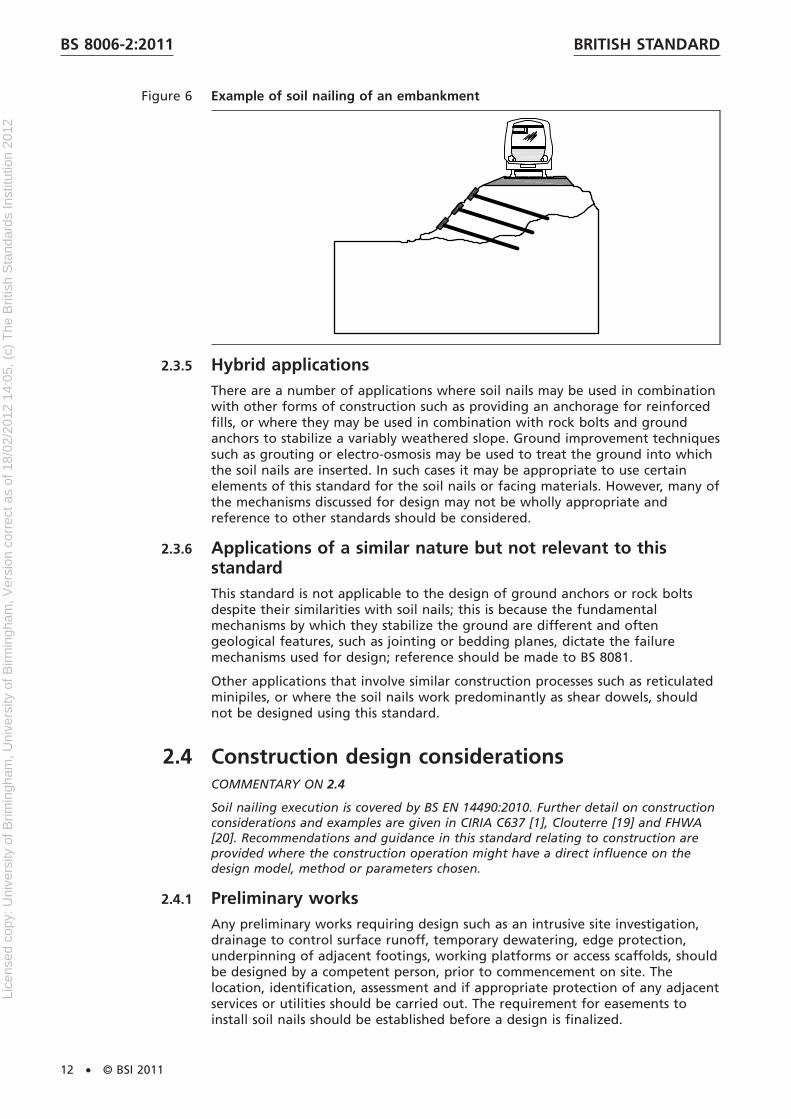
Figure 6 Example of soil nailing of an embankment
2.3.5 Hybrid applicationsThere are a number of applications where soil nails may be used in combinationwith other forms of construction such as providing an anchorage for reinforcedfills, or where they may be used in combination with rock bolts and groundanchors to stabilize a variably weathered slope. Ground improvement techniquessuch as grouting or electro-osmosis may be used to treat the ground into whichthe soil nails are inserted. In such cases it may be appropriate to use certainelements of this standard for the soil nails or facing materials. However, many ofthe mechanisms discussed for design may not be wholly appropriate andreference to other standards should be considered.
2.3.6 Applications of a similar nature but not relevant to thisstandardThis standard is not applicable to the design of ground anchors or rock boltsdespite their similarities with soil nails; this is because the fundamentalmechanisms by which they stabilize the ground are different and oftengeological features, such as jointing or bedding planes, dictate the failuremechanisms used for design; reference should be made to BS 8081.
Other applications that involve similar construction processes such as reticulatedminipiles, or where the soil nails work predominantly as shear dowels, shouldnot be designed using this standard.
2.4 Construction design considerationsCOMMENTARY ON 2.4
Soil nailing execution is covered by BS EN 14490:2010. Further detail on constructionconsiderations and examples are given in CIRIA C637 [1], Clouterre [19] and FHWA[20]. Recommendations and guidance in this standard relating to construction areprovided where the construction operation might have a direct influence on thedesign model, method or parameters chosen.
2.4.1 Preliminary worksAny preliminary works requiring design such as an intrusive site investigation,drainage to control surface runoff, temporary dewatering, edge protection,underpinning of adjacent footings, working platforms or access scaffolds, shouldbe designed by a competent person, prior to commencement on site. Thelocation, identification, assessment and if appropriate protection of any adjacentservices or utilities should be carried out. The requirement for easements toinstall soil nails should be established before a design is finalized.
BRITISH STANDARDBS 8006-2:2011
12 • © BSI 2011
Lice
nsed
cop
y: U
nive
rsity
of B
rimin
gham
, Uni
vers
ity o
f Birm
ingh
am, V
ersi
on c
orre
ct a
s of
18/
02/2
012
14:0
5, (
c) T
he B
ritis
h S
tand
ards
Inst
itutio
n 20
12

Where monitoring is required as a part of the design then baseline readings andbackground influences should be recorded prior to commencement to permitthe necessary control during construction. The designer should also providealarm and intervention trigger levels and the appropriate actions to be taken inevent of them being exceeded.
2.4.2 Excavation and face preparationWhere the soil nailing process includes excavation, the designer should considerplacing limits on the maximum depths, lengths and slope angles that can beexcavated and specifying these to the constructor. The maximum height of cutslope that can safely stand unsupported until nail installation and facingconstruction should be taken into account when specifying the nail spacing.
The design of an excavated slope needs to address both the local (internal)stability of the soil nailed face and the global (external) stability of the wholeslope (Figure 7). The criteria for internal and external stability are addressed inSection 4.
BS EN 14490:2010 gives details of face stability assessment tests that should beconsidered in the assessment of temporary stability and excavation benchheights. The maximum bench height needs to be considered when determiningthe vertical nail spacing.
The risk of undercutting increases with the steepness of the cut face. For verysteep faces this could lead to dramatic reductions in stability. In such casesgreater control of face trimming is required. The designer should specify thetolerances upon which the design is based, taking into account the structure andfabric of the ground and the likely excavation methods to be used. As a generalrule slope excavation should start within 50 mm of the design crest. Theexcavation should be cut to within 2.5° of the design slope angle (β) [Figure 8a)].Deviation from the design slope between nails should not exceed the lesser ofeither the nail spacing divided by 20 mm or 50mm [Figure 8b)]. Local bumps andindentations are permitted, provided they do not affect the integrity of thefacing.
NOTE Control of face trimming is important as an uneven face can affect theperformance of, or ability to, correctly construct the facing. The positioning of nailheads can become problematic and wastage of materials increases.
If a design is sensitive to the changes in ground conditions, the design shouldclearly state the expected conditions and acceptable variations in strength orlocation of individual strata, with instructions on reporting back to the designer.
BRITISH STANDARD BS 8006-2:2011
© BSI 2011 • 13
Lice
nsed
cop
y: U
nive
rsity
of B
rimin
gham
, Uni
vers
ity o
f Birm
ingh
am, V
ersi
on c
orre
ct a
s of
18/
02/2
012
14:0
5, (
c) T
he B
ritis
h S
tand
ards
Inst
itutio
n 20
12
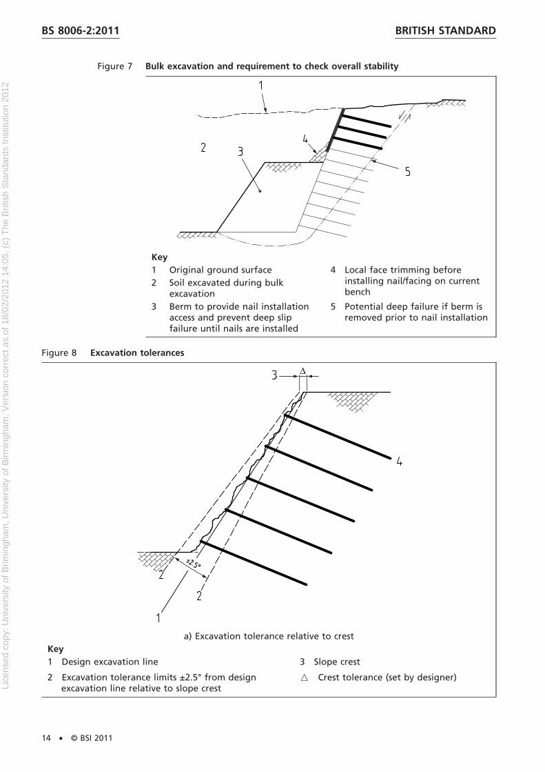
Figure 7 Bulk excavation and requirement to check overall stability
Key1 Original ground surface 4 Local face trimming before
installing nail/facing on currentbench
2 Soil excavated during bulkexcavation
3 Berm to provide nail installationaccess and prevent deep slipfailure until nails are installed
5 Potential deep failure if berm isremoved prior to nail installation
Figure 8 Excavation tolerances
a) Excavation tolerance relative to crestKey1 Design excavation line
2 Excavation tolerance limits ±2.5° from designexcavation line relative to slope crest
3 Slope crest
_ Crest tolerance (set by designer)
BRITISH STANDARDBS 8006-2:2011
14 • © BSI 2011
Lice
nsed
cop
y: U
nive
rsity
of B
rimin
gham
, Uni
vers
ity o
f Birm
ingh
am, V
ersi
on c
orre
ct a
s of
18/
02/2
012
14:0
5, (
c) T
he B
ritis
h S
tand
ards
Inst
itutio
n 20
12

Figure 8 Excavation tolerances
b) Suggested local trimming tolerance between nail rowsKey1 Design excavation line
2 Actual excavated face
3 Tolerance limit between nail rows
4 Soil nails
S Spacing between nail rows measured parallelto the face
2.4.3 Nail installation
2.4.3.1 General
The method of nail installation chosen will have a direct impact on the pulloutresistance that may be used in the design. Some methods of nail installationmay be deemed inappropriate because of the specified nail length and diameter,ground conditions, required durability or equipment required for installationwhen taking into account the safe access or manual handling requirements.
2.4.3.2 Soil nail installation tolerance
The designer should take into account the requirements of the facing whenspecifying nail installation tolerances. The nail location on the face shouldgenerally not be specified as less than ±100 mm and the nail orientation to lessthan ±5°. Potential clashing of soil nails should be considered.
2.4.3.3 Direct installation methods
Direct installation methods include driven (percussive and vibratory), jacked andfired soil nails. When selecting these methods the designer should consider theimplications of refusal of the nail before the design penetration has beenreached and the potential for damage during installation that could affectdurability. Compared to other installation methods, direct installation tends toutilise relatively short, small diameter, soil nails. The relatively small surface areaof each nail generally results in a higher density of nails than for an equivalentdrilled soil nail design.
BRITISH STANDARD BS 8006-2:2011
© BSI 2011 • 15
Lice
nsed
cop
y: U
nive
rsity
of B
rimin
gham
, Uni
vers
ity o
f Birm
ingh
am, V
ersi
on c
orre
ct a
s of
18/
02/2
012
14:0
5, (
c) T
he B
ritis
h S
tand
ards
Inst
itutio
n 20
12
2.4.3.4 Drilled installation methods
Drilled methods may be used in all soil types, for a wide range of nail diameters,lengths and durability systems. They should nearly always include grouting.
The drilling method and flushing medium (if used) can affect the frictionbetween the nail and the ground and consideration of potential effects shouldbe made.
NOTE Potential adverse effects of drilling methods include softening of cohesivesoils by water flush, scour of granular soils by air flush and smearing of the borewalls through augering.
A requirement for casing to be used should be assessed and the ability to installthe nail element whilst keeping it clean prior to grouting should be consideredcarefully and where appropriate taken into account in the design.
In general, keeping the cycle time between nail drilling and grouting to aminimum is beneficial with respect to the frictional resistance available; testnails should be constructed to be representative of the production nails.
The nail design should ensure that the method of installation addressescontinuity of the corrosion protection system over its entire length and into anyfacing system or head plates/bearing pads.
2.4.4 GroutingNOTE 1 Effective grouting is important in achieving the design frictional resistanceand required durability. Most soil nails involve grouting under gravity, but in somesoils grouting as a part of the drilling process or grouting at an elevated pressurecan enhance the friction available between the nail and the ground (see 4.3).
Where the design is based upon the benefit of elevated grout pressures thenthe designer should consider the use of design investigation tests or suitabilitytests to confirm the enhancement achieved.
NOTE 2 Grout take is the volume of grout that has to be injected to completely fillthe annulus around a drilled soil nail. Grout loss can be defined as the volume ofgrout take exceeding the design or expected volume. It occurs when injected groutescapes into the interstitial voids of the soil in greater quantities than predicted. It isa particular risk in clean, coarse granular soils. Possible mitigation measures includeincreasing grout viscosity (e.g. using sanded grout mixes or gelling agents) orapplying multiple injections of grout. The soil nail designer needs to be alert to theincreased risk of grout loss in granular soils and make adequate provision to dealwith the consequences.
The designer should specify the characteristic grout strength to be achieved insamples before loading of the nails to prevent damage and to achieve thedurability required. Minimum characteristic strengths of 5 N/mm2 and 25 N/mm2
prior to loading and at 28 days respectively should be specified, as required byBS EN 14490:2010.
NOTE 3 BS EN 14490:2010 requires a minimum cube strength of 5 N/mm2 to beachieved prior to excavation below a nail.
Typically grout should comprise water mixed with a BS EN 197-1:2000, CEM I orCEM II cement in the ratio in the range 0.40 to 0.45. Sand filler and admixturesmay be used in the grout in some instances.
NOTE 4 The high cement content of cementitious grouts generally makes themdurable. At the time of writing, however, there is limited information on groutdurability in contact with ground and groundwater. Guidance developed forconcrete (e.g. BRE SD1 [3]) is not directly applicable.
BRITISH STANDARDBS 8006-2:2011
16 • © BSI 2011
Lice
nsed
cop
y: U
nive
rsity
of B
rimin
gham
, Uni
vers
ity o
f Birm
ingh
am, V
ersi
on c
orre
ct a
s of
18/
02/2
012
14:0
5, (
c) T
he B
ritis
h S
tand
ards
Inst
itutio
n 20
12

Time should be allowed for the grout to develop sufficient strength beforeplanned loading of the soil nails. This requirement is particularly applicable tosituations where soil nails are installed to support a planned excavation. In suchcases the designer should clearly state the requirements for time to elapsebetween installation of the soil nails and start of excavation.
2.4.5 Drainage installationGeneral slope drainage and that required to control runoff are not consideredin this standard but should be considered as a part of the overall scheme design.However, it is essential that the soil nail designer considers the nature of anydrainage required to ensure design assumptions on groundwater orpore-pressures can be met during the design life of the structure. Wheremembrane type drains are positioned behind facings then the risk of damageand the hydraulic continuity of joints should be considered. If deep-drilled drainsare to be installed there may be restrictions on the angle and head elevation ofthese imposed by the installation equipment. Access for maintenance should beconsidered, especially where new structures are located in front of the soilnailed slope. Maintenance requirements for drainage should be clearly specifiedby the designer and safe access considered as a part of the design.
2.4.6 Facing installationThere are too many facing types to outline the key construction features thatinterface with design (as described in 4.7), however, attention to detail in thedesign is critical for the facing to achieve its aesthetic, serviceability anddurability requirements. Specific construction issues that should be raised at anearly stage of the design process include:
a) relative tolerances on the prepared ground face, soil nails and facingconnections;
b) how joints between facing sections can be achieved;
c) connections between head plates and facings;
d) continuity of nail durability system/corrosion protection through the facing;
e) drainage and facing interfaces;
f) the sequencing of facing construction and access;
g) interfaces between safety barriers, etc., and the facing and whether relativemovement during construction needs to be considered.
Soil nail facings should be constructed to prevent loosening of the groundimmediately behind.
BRITISH STANDARD BS 8006-2:2011
© BSI 2011 • 17
Lice
nsed
cop
y: U
nive
rsity
of B
rimin
gham
, Uni
vers
ity o
f Birm
ingh
am, V
ersi
on c
orre
ct a
s of
18/
02/2
012
14:0
5, (
c) T
he B
ritis
h S
tand
ards
Inst
itutio
n 20
12
Section 3 : Suitability of ground and groundwaterconditions
3.1 GeneralNOTE 1 Not all soils are suitable for nailing. Some soils present problems eitherduring construction or in the long term, which make soil nailing impractical,uneconomical or unsafe as a solution. Recognition of such conditions at an earlystage is vital to prevent selection of an inappropriate scheme.
Designers should obtain site-specific information on the geological andhydrogeological conditions and use this information to determine the specificrisks and suitability of soil nailing.
Recommendations on the suitability of different ground conditions for soilnailing are discussed in this standard, based on the following principal materialtypes and their characteristic properties.
a) Cohesive soils.
b) Granular soils.
c) Soft/weak rocks.
NOTE 2 Soil nailing has been used in a wide variety of the ground conditions thatexist in the UK. A range of soil nailing equipment and construction techniques hasbeen developed by specialist contractors to accommodate different groundconditions. Selecting the right technique requires knowledge of the prevailingconditions at the site.
3.2 Understanding the site geologyBy its very nature, the successful application of soil nailing is highly dependanton the suitability of the ground conditions; a thorough understanding of thegeological and hydrogeological setting of the site is imperative to assess thesuitability of the technique for a given project. This understanding shouldinclude not only the material within which the soil nails would be installed butalso the underlying strata, which may affect the global stability or deformationof the soil-nailed system.
The designer should consider a number of key questions about the geology ofthe site to determine its suitability for soil nailing including the following.
a) Does the site comprise natural or made ground?
b) What are the characteristic properties of the soil to be nailed? Is it cohesiveor granular (or something in between) in its behaviour? Is it stiff/dense orsoft/loose? Can the ground conditions be considered as homogeneous?
c) What is the nature of the underlying soil/rock?
d) What is the structure of the deposits: bedding, fissures, joints, fracturesand/or laminations?
e) What chemical and mechanical processes are occurring or have occurred atthe site?
f) What has the site previously been used for? Could there be any sources ofcontamination on the site? How might they affect construction workers andend users of the site? How might they affect durability of materials used inthe proposed scheme and the need for special measures?
g) Does the site have a history of stability problems (pre-existing slopefailures)?
BRITISH STANDARDBS 8006-2:2011
18 • © BSI 2011
Lice
nsed
cop
y: U
nive
rsity
of B
rimin
gham
, Uni
vers
ity o
f Birm
ingh
am, V
ersi
on c
orre
ct a
s of
18/
02/2
012
14:0
5, (
c) T
he B
ritis
h S
tand
ards
Inst
itutio
n 20
12

h) What are the groundwater conditions?
i) What are the potential deformation mechanisms (including groundwaterand/ or vegetation induced mechanisms and collapse potential)?
Many of these questions should and can only be adequately addressed by acomprehensive site investigation following a desk study and scrutiny by ageotechnical specialist. However, to make a preliminary assessment of thesuitability of the ground for soil nailing, sufficient knowledge of the siteconditions may usually be obtained from published geological informationcombined with a walkover survey of the site.
3.3 General requirements for suitability of soils androcks for soil nailingThe success of a soil nailing scheme relies on the ability to form an adequatebond between the nail and the soil into which it is installed; for soil nailing tobe economical, the soil should have sufficient shear strength to develop such abond.
Steepening of existing slopes is often achieved through a cyclic sequence ofbenching and nailing. The faces to be nailed are typically between 1 m and 3 mhigh and need to stand unsupported pending installation of the soil nails. It isessential that the soil has sufficient shear strength to allow the bench faces tobe formed and remain adequately stable in the temporary condition.
NOTE The suitability of typical UK soils and rocks for soil nailing is summarized inTable 1.
3.4 Suitability of cohesive soils for soil nailing
3.4.1 Soft clays and siltsSoft clays and silts are generally unsuitable for soil nailing.
3.4.2 Firm and stiff claysSoil nailing is generally well suited to firm and stiff clays (i.e. clays with anundrained shear strength of 50 kN/m2 or greater). Such clays are usuallyoverconsolidated. They generally provide sufficient stand-up time duringexcavation of benches to permit progress without immediate support of the cutface. They may also be assumed to provide good bore stability for drilled andgrouted nails without the need for casing. Sufficient bond strength may usuallybe achieved, particularly in slopes where tension forces in the nails are relativelylow.
3.4.3 Potential problems associated with soil nailing in cohesivesoils
3.4.3.1 Shrinking and swelling
High plasticity clays have the potential to develop significant shrink/swellbehaviour due to changes in moisture content. This might be due to cyclicchanges in moisture content through precipitation and/or the effects ofvegetation. Soil nailing may only be appropriate in these soils if it can bedemonstrated that the design will cater for such potential deformations.
BRITISH STANDARD BS 8006-2:2011
© BSI 2011 • 19
Lice
nsed
cop
y: U
nive
rsity
of B
rimin
gham
, Uni
vers
ity o
f Birm
ingh
am, V
ersi
on c
orre
ct a
s of
18/
02/2
012
14:0
5, (
c) T
he B
ritis
h S
tand
ards
Inst
itutio
n 20
12

NOTE High plasticity, overconsolidated clays are very prone to volume change onwetting and drying. This is due to the presence of clay minerals of the smectitegroup, such as montmorillonite, which have “shrink/swell” properties. Soil-nailedslopes in such materials can suffer from deterioration, particularly at the crest andthe face, due to repeated seasonal wetting and drying causing cyclic swelling andshrinking of the clay. This can result in corresponding fluctuations in the nail loadingas well as localized slumping at the face. Clays having lower plasticity, due to alower proportion of clay particles or lower proportions of smectite minerals are lessinclined to shrink and swell.
Water flush should not be used to facilitate drilling in clays, as it will causesoftening of the clay.
3.4.3.2 Previous disturbance and slope instability
Shear strength parameters for design of soil nailing in clays should be selectedto reflect the degree of disturbance caused to the clay by previous activity andby the proposed works. For example, if a slope has suffered from previous slipfailures, pre-existing shear planes might exist over which lower strengths applyand allowance should be made for the existence of such planes in design, bothwithin the soil-nailed block and beneath it (Figure 9).
NOTE For high plasticity clays, the residual strength of the clay when it is sheared ismuch lower than the peak strength of the intact material.
BRITISH STANDARDBS 8006-2:2011
20 • © BSI 2011
Lice
nsed
cop
y: U
nive
rsity
of B
rimin
gham
, Uni
vers
ity o
f Birm
ingh
am, V
ersi
on c
orre
ct a
s of
18/
02/2
012
14:0
5, (
c) T
he B
ritis
h S
tand
ards
Inst
itutio
n 20
12

Tab
le1
Sum
mar
yo
fg
rou
nd
con
dit
ion
sb
est
suit
edan
dle
ssw
ell
suit
edto
soil
nai
ling
Dev
elo
ped
fro
mFH
WA
,19
98[1
9](T
his
isTa
ble
4.1
fro
mC
IRIA
C63
7[1
].)
Gro
un
dco
nd
itio
ns
bes
tsu
ited
toso
iln
ailin
gG
rou
nd
con
dit
ion
sle
sssu
itab
lefo
rso
iln
ailin
gPo
ssib
lem
easu
res
toim
pro
vesu
itab
ility
of
gro
un
dco
nd
itio
ns
Mat
eria
lto
be
nai
led
firm
tost
iff,
low
pla
stic
ity
clay
sso
ftco
hes
ive
and
org
anic
soils
pro
ne
tocr
eep
def
orm
atio
nn
on
ew
illim
pro
veth
ese
soils
suff
icie
ntl
yfo
rso
iln
ailin
g
hig
hp
last
icit
yo
rh
igh
lyfr
ost
susc
epti
ble
soils
and
rock
sp
rovi
de
adeq
uat
ep
rote
ctio
nag
ain
stw
etti
ng
and
dry
ing
wel
lg
rad
edso
ilsh
avin
ga
coh
esiv
em
atri
xsu
chas
som
eg
laci
alti
lls,
pro
vid
edth
atco
bb
les
and
bo
uld
ers
do
no
to
bst
ruct
nai
lin
stal
lati
on
fin
eto
med
ium
san
ds
and
silt
ysa
nd
sw
ith
som
eap
par
ent
coh
esio
n
med
ium
den
seto
den
sesa
nd
san
dg
rave
lsw
ith
som
eap
par
ent
coh
esio
n.
loo
se,
clea
nsa
nd
san
dg
rave
lsw
ith
littl
eo
rn
oap
par
ent
coh
esio
np
re-g
rou
tin
go
rg
rou
nd
free
zin
gto
imp
rove
tem
po
rary
stab
ility
limit
exca
vati
on
hei
gh
ts/le
ng
ths
wea
ther
edro
ckw
ith
ou
tad
vers
ejo
int
ori
enta
tio
nw
eath
ered
rock
wit
had
vers
ejo
int
ori
enta
tio
no
rvo
ids
eng
inee
red
fills
com
pri
sin
gse
lect
edn
atu
ral
or
un
ifo
rm,
no
n-a
gg
ress
ive
mat
eria
lsth
ath
ave
bee
nca
refu
llyp
lace
dan
dw
ell
com
pac
ted
toac
hie
vech
arac
teri
stic
ssi
mila
rto
tho
seo
fth
en
atu
ral
soils
des
crib
edab
ove
no
n-e
ng
inee
red
fills
,p
arti
cula
rly
tho
seco
nta
inin
gva
riab
le,
agg
ress
ive
and
/or
deg
rad
able
con
stit
uen
tsth
atar
ep
ron
eto
colla
pse
and
dif
fere
nti
alse
ttle
men
t(a
nd
ob
stru
ctio
ns)
exca
vate
,so
rtre
-usa
ble
mat
eria
lan
dre
pla
ce(u
nlik
ely
tob
eco
stef
fect
ive)
iffi
llco
nst
itu
ents
are
suit
able
,g
rou
nd
imp
rove
men
tm
eth
od
sm
ayb
eu
sed
tore
du
ceth
eri
sko
fco
llap
sese
ttle
men
t,su
chas
gro
uti
ng
,vi
bro
-sto
ne
colu
mn
san
dd
ynam
icco
mp
acti
on
Gro
un
dw
ater
con
dit
ion
sab
ove
the
gro
un
dw
ater
tab
lew
ith
ad
ryex
cava
ted
face
bel
ow
the
wat
erta
ble
tem
po
rary
and
per
man
ent
dew
ater
ing
arte
sian
gro
un
dw
ater
atd
epth
sho
uld
be
acco
mm
od
ated
wit
hin
the
des
ign
,b
oth
inte
rms
of
inte
rnal
and
exte
rnal
stab
ility
per
ched
wat
ero
rg
rou
nd
wat
erse
epag
eth
rou
gh
gra
nu
lar
soils
or
po
cket
ste
mp
ora
ryd
ewat
erin
gan
dp
erm
anen
td
rain
age
mea
sure
sto
ensu
relo
ng
term
stab
ility
of
the
slo
pe
or
wal
l.
Un
der
lyin
gg
rou
nd
con
dit
ion
san
dg
eolo
gic
alfe
atu
res
un
der
lyin
gco
nd
itio
ns
and
geo
log
ical
feat
ure
sth
atd
on
ot
com
pro
mis
eth
est
abili
tyan
dp
erfo
rman
ceo
fth
eso
iln
aile
dst
ruct
ure
adve
rse
un
der
lyin
gg
rou
nd
con
dit
ion
san
dg
eolo
gic
alfe
atu
res
such
as:
pre
-exi
stin
gsl
ipsu
rfac
eso
rad
vers
ejo
inti
ng
soft
,co
mp
ress
ible
laye
rsu
nle
ssst
ren
gth
ened
bef
ore
soil
nai
ling
void
ssu
chas
solu
tio
nfe
atu
res
or
min
ing
cavi
ties
liqu
efia
ble
silt
yso
ils
po
ssib
lem
easu
res
will
dep
end
on
nat
ure
of
the
adve
rse
con
dit
ion
s/fe
atu
res
and
has
tob
eas
sess
edo
na
site
spec
ific
bas
is
BRITISH STANDARD BS 8006-2:2011
© BSI 2011 • 21
Lice
nsed
cop
y: U
nive
rsity
of B
rimin
gham
, Uni
vers
ity o
f Birm
ingh
am, V
ersi
on c
orre
ct a
s of
18/
02/2
012
14:0
5, (
c) T
he B
ritis
h S
tand
ards
Inst
itutio
n 20
12
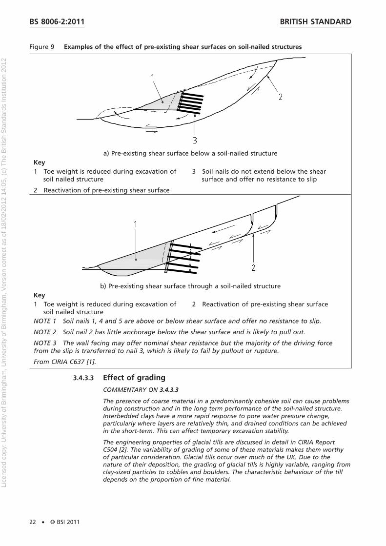
Figure 9 Examples of the effect of pre-existing shear surfaces on soil-nailed structures
a) Pre-existing shear surface below a soil-nailed structureKey1 Toe weight is reduced during excavation of
soil nailed structure
2 Reactivation of pre-existing shear surface
3 Soil nails do not extend below the shearsurface and offer no resistance to slip
b) Pre-existing shear surface through a soil-nailed structureKey1 Toe weight is reduced during excavation of
soil nailed structure2 Reactivation of pre-existing shear surface
NOTE 1 Soil nails 1, 4 and 5 are above or below shear surface and offer no resistance to slip.
NOTE 2 Soil nail 2 has little anchorage below the shear surface and is likely to pull out.
NOTE 3 The wall facing may offer nominal shear resistance but the majority of the driving forcefrom the slip is transferred to nail 3, which is likely to fail by pullout or rupture.
From CIRIA C637 [1].
3.4.3.3 Effect of grading
COMMENTARY ON 3.4.3.3
The presence of coarse material in a predominantly cohesive soil can cause problemsduring construction and in the long term performance of the soil-nailed structure.Interbedded clays have a more rapid response to pore water pressure change,particularly where layers are relatively thin, and drained conditions can be achievedin the short-term. This can affect temporary excavation stability.
The engineering properties of glacial tills are discussed in detail in CIRIA ReportC504 [2]. The variability of grading of some of these materials makes them worthyof particular consideration. Glacial tills occur over much of the UK. Due to thenature of their deposition, the grading of glacial tills is highly variable, ranging fromclay-sized particles to cobbles and boulders. The characteristic behaviour of the tilldepends on the proportion of fine material.
BRITISH STANDARDBS 8006-2:2011
22 • © BSI 2011
Lice
nsed
cop
y: U
nive
rsity
of B
rimin
gham
, Uni
vers
ity o
f Birm
ingh
am, V
ersi
on c
orre
ct a
s of
18/
02/2
012
14:0
5, (
c) T
he B
ritis
h S
tand
ards
Inst
itutio
n 20
12

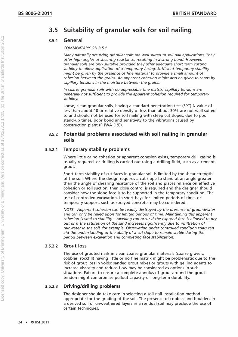
Glacial and periglacial deposits where the clay fraction dominates, might still containa significant proportion of coarse material, variably distributed within the finermatrix. Soil nailing is well suited to such mixed soils although larger particles andlocalized granular pockets can present some difficulties (Figure 10). Boulders andcobbles can obstruct drilling or driving or cause deflection. Localized problems canoccur with stand-up time of temporary excavations and with stability of bores wherezones of more granular material occur, particularly where seepage of groundwateroccurs, with resulting wash-out of fines and loss of cohesion. Softening of the claymatrix occurs around seepage pathways (see 3.8). Loss or washout of grout can occurinto the granular material, although this rarely takes place in large volumes sincegranular material generally occurs in discrete, discontinuous pockets. Problems canalso occur with the loss of air flush during drilling in glacial till of variable grading.
Figure 10 Problems caused by granular material in glacial till
Based on CIRIA C637 [1].
3.4.3.4 Aggressive ground conditions
NOTE Compared with other solid geology, the weathered zones of the sedimentaryclays are the most likely soils to contain high concentrations of sulfates (BRE SD1 [3]).This presents a risk of sulfate attack on soil-nail grout and concrete facings. Mineralssuch as pyrite and gypsum in an unweathered state can rapidly deteriorate ifexposed to air and water during construction. Weathering of these minerals willrelease water soluble sulfates.
3.4.3.5 Drilling/driving problems
NOTE Very stiff clays are likely to be too resistant for successful construction ofdirectly installed soil nails; drilled soil nail systems might be more appropriate.Ground consisting of interbedded clays, granular layers of rock can produce difficultconditions for augering and direct soil nail installation.
BRITISH STANDARD BS 8006-2:2011
© BSI 2011 • 23
Lice
nsed
cop
y: U
nive
rsity
of B
rimin
gham
, Uni
vers
ity o
f Birm
ingh
am, V
ersi
on c
orre
ct a
s of
18/
02/2
012
14:0
5, (
c) T
he B
ritis
h S
tand
ards
Inst
itutio
n 20
12
3.5 Suitability of granular soils for soil nailing
3.5.1 GeneralCOMMENTARY ON 3.5.1
Many naturally occurring granular soils are well suited to soil nail applications. Theyoffer high angles of shearing resistance, resulting in a strong bond. However,granular soils are only suitable provided they offer adequate short term cuttingstability to allow application of a temporary facing. Sufficient temporary stabilitymight be given by the presence of fine material to provide a small amount ofcohesion between the grains. An apparent cohesion might also be given to sands bycapillary tensions in the moisture between the grains.
In coarse granular soils with no appreciable fine matrix, capillary tensions aregenerally not sufficient to provide the apparent cohesion required for temporarystability.
Loose, clean granular soils, having a standard penetration test (SPT) N value ofless than about 10 or relative density of less than about 30% are not well suitedto and should not be used for soil nailing with steep cut slopes, due to poorstand-up times, poor bond and sensitivity to the vibrations caused byconstruction plant (FHWA [19]).
3.5.2 Potential problems associated with soil nailing in granularsoils
3.5.2.1 Temporary stability problems
Where little or no cohesion or apparent cohesion exists, temporary drill casing isusually required, or drilling is carried out using a drilling fluid, such as a cementgrout.
Short term stability of cut faces in granular soil is limited by the shear strengthof the soil. Where the design requires a cut slope to stand at an angle greaterthan the angle of shearing resistance of the soil and places reliance on effectivecohesion or soil suction, then close control is required and the designer shouldconsider how the slope face is to be supported in the temporary condition. Theuse of controlled excavation, in short bays for limited periods of time, ortemporary support, such as sprayed concrete, may be considered.
NOTE Apparent cohesion can be readily destroyed by the presence of groundwaterand can only be relied upon for limited periods of time. Maintaining this apparentcohesion is vital to stability – ravelling can occur if the exposed face is allowed to dryout or if the saturation of the sand increases significantly due to infiltration ofrainwater in the soil, for example. Observation under controlled condition trials canaid the understanding of the ability of a cut slope to remain stable during theperiod between excavation and completing face stabilization.
3.5.2.2 Grout loss
The use of grouted nails in clean coarse granular materials (coarse gravels,cobbles, rockfill) having little or no fine matrix might be problematic due to therisk of grout loss in voids; sanded grout mixes or grouts with gelling agents toincrease viscosity and reduce flow may be considered as options in suchsituations. Failure to ensure a complete annulus of grout around the grouttendon might compromise pullout capacity or long-term durability.
3.5.2.3 Driving/drilling problems
The designer should take care in selecting a soil nail installation methodappropriate for the grading of the soil. The presence of cobbles and boulders ina derived soil or unweathered layers in a residual soil may preclude the use ofcertain techniques.
BRITISH STANDARDBS 8006-2:2011
24 • © BSI 2011
Lice
nsed
cop
y: U
nive
rsity
of B
rimin
gham
, Uni
vers
ity o
f Birm
ingh
am, V
ersi
on c
orre
ct a
s of
18/
02/2
012
14:0
5, (
c) T
he B
ritis
h S
tand
ards
Inst
itutio
n 20
12

3.6 Suitability of weak rocks for soil nailing
3.6.1 GeneralSteep slopes in weak or highly weathered rocks may be amenable tostabilization using soil nails. An appropriate method of nail installation, capableof penetrating inter-bedded strata of contrasting hardness, should be selectedby the designer. Drilling to produce a rough bore surface generally provides anexcellent bond. Provided the geological structure is favourably oriented (seeFigure 11), weathered and weak rocks may be relied upon to offer goodstand-up times for excavated faces. Particular guidance on the properties ofspecific rock types should be sought – examples of published guidance includeCIRIA C570 [4], which provides detailed guidance on the behaviour of MerciaMudstone, and CIRIA C574 [5], which gives advice on engineering in chalk.
3.6.2 Potential problems associated with soil nailing in weak rocks
3.6.2.1 Adverse bedding and jointing
NOTE Adverse jointing can result in stability problems in both the short and longterm, particularly if joints contain low strength fine material on which blocks ofintact rock can slide (Figure 11).
3.6.2.2 Effects of weathering/disturbance
NOTE Weathered rocks which are prone to degradation result in materials whichexhibit the same advantages and disadvantages as the equivalent soil type.
3.6.2.3 Dissolution
NOTE Calcareous rocks (chalk, limestone) are prone to dissolution. The risk ofdissolution features in chalk is significant. Voids form by gradual dissolution of thechalk, particularly along joints and fissures where water flows readily. These featuresare generally infilled with material that has infiltrated from overlying recentdeposits. Dissolution features are often relatively small (up to a few cubic metres involume) so their presence might not be identified during routine site investigations(see 3.10).
3.6.2.4 Other voids
NOTE Shallow voids resulting from mining operations such as bell-pits and adits arecommon where the coal measures outcrop in the Midlands and North of England(particularly in Lancashire and Yorkshire) and in Wales and Scotland. Localizedquarry pits used to obtain rocks and minerals for construction and industrialprocesses can also result in hollow or infilled voids in the ground.
3.6.2.5 Aggressive ground conditions
NOTE Sulfates are commonly found in the weathered zone of most mudstones andshales where sulfurous minerals such as pyrite and gypsum (in relatively highconcentrations) have oxidized in the presence of air and water. Sulfates attackcementitious materials and can result in degradation of grouted nails and concretefacings (see 3.14 and 3.15).
BRITISH STANDARD BS 8006-2:2011
© BSI 2011 • 25
Lice
nsed
cop
y: U
nive
rsity
of B
rimin
gham
, Uni
vers
ity o
f Birm
ingh
am, V
ersi
on c
orre
ct a
s of
18/
02/2
012
14:0
5, (
c) T
he B
ritis
h S
tand
ards
Inst
itutio
n 20
12
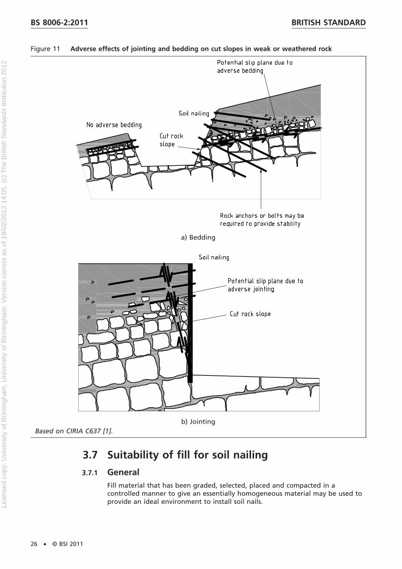
Figure 11 Adverse effects of jointing and bedding on cut slopes in weak or weathered rock
a) Bedding
b) JointingBased on CIRIA C637 [1].
3.7 Suitability of fill for soil nailing
3.7.1 GeneralFill material that has been graded, selected, placed and compacted in acontrolled manner to give an essentially homogeneous material may be used toprovide an ideal environment to install soil nails.
BRITISH STANDARDBS 8006-2:2011
26 • © BSI 2011
Lice
nsed
cop
y: U
nive
rsity
of B
rimin
gham
, Uni
vers
ity o
f Birm
ingh
am, V
ersi
on c
orre
ct a
s of
18/
02/2
012
14:0
5, (
c) T
he B
ritis
h S
tand
ards
Inst
itutio
n 20
12

COMMENTARY ON 3.7.1
This is commonly referred to as engineered fill. Fills placed in more recentdevelopments, such as reclamation works, highway and rail embankments tend to beengineered fills.
However, the majority of existing fill materials encountered in the UK do not fallinto this category. More commonly, fills have historically been produced and placedwithout careful consideration of their properties and behaviour. They can haveadverse characteristics including some or all of being:
a) variable in terms of nature and distribution of its constituents (heterogeneous);
b) soft or weak;
c) degradable;
d) loose due to poor placing and compaction;
e) poorly graded;
f) gas bearing; and/or
g) chemically aggressive.
Fill may be judged to be suitable for effective treatment by soil nailing broadlydepending on:
1) the nature and grading of the constituent particles of the fill, whichgenerally depends on the source of the fill material;
2) the density and strength of the fill resulting from the method of itsplacement and compaction and its age as well as the nature of theconstituent particles; and
3) the potential for volume change due to external or internal mechanismsother than by gravity loading or imposed surface loads, for example collapseon wetting and chemical instability.
NOTE The Building Research Establishment report Building on fill: geotechnicalaspects (Charles and Watts [10]) gives detailed guidance on the properties andbehaviour of fills commonly encountered in the UK and the geotechnical problemsassociated with them.
3.7.2 Potential problems associated with soil nailing in engineeredfillsProviding a fill has been placed and compacted in a controlled manner, itssuitability for soil nailing may generally be judged depending on thecharacteristics of the source material. The advantages and limitations of usingsoil nailing in a natural granular deposit may also be assumed to apply to agranular fill. Likewise, cohesive fill may be assumed to exhibit similar advantagesand limitations as a naturally occurring clay soil; however, the process ofexcavating, transporting, placing and compacting the material results in thefollowing changes to the engineering properties of the fill material comparedwith its original intact state.
a) The excavation process can result in some mixing with other soils,particularly where material is excavated from a narrow or interbeddedstratum. Excavation and handling can cause damage to the soil particles,resulting in a reduction in the grading size.
b) In granular soils, excavation destroys any apparent cohesion, which mightnot be re-established when the fill is placed and compacted. When placingand compacting rock fill and granular soils, it may not be possible toachieve the density of the previously intact material without breaking thegrains. This can result in a lower bond strength than might be predicted
BRITISH STANDARD BS 8006-2:2011
© BSI 2011 • 27
Lice
nsed
cop
y: U
nive
rsity
of B
rimin
gham
, Uni
vers
ity o
f Birm
ingh
am, V
ersi
on c
orre
ct a
s of
18/
02/2
012
14:0
5, (
c) T
he B
ritis
h S
tand
ards
Inst
itutio
n 20
12
from the properties of the natural source material. Safe heights andstand-up time for excavations might also be reduced.
c) Cohesive soils are excavated in blocks or lumps. When placed andcompacted, the clay “lumps” deform, causing remoulding and weakening ofthe clay material. Voids remain between the lumps, although they might befilled to some extent by fines generated during excavation and handling.This can result in locally lower bond strengths. Grout loss into voids can alsooccur.
d) The homogeneity of the resulting fill structure will depend on the degree ofquality control of the placing and compaction process. Where site practicesdiffer from the recommended methods, greater variability of the fill densitythan expected can result.
It is therefore important to understand the characteristic properties of the fill inits present, as-placed state.
3.7.3 Potential problems associated with soil nailing in historic fillsCOMMENTARY ON 3.7.3
The age of the fill is significant. In older fills, the design and construction techniquesused at the time differed significantly from modern day standards and methods.Thus a fill might have been placed with an engineering purpose in mind, such as fora road or railway embankment, but might not have been selected, placed andcompacted to modern standards. Railway embankments many decades old wereoften constructed with ash and other materials derived from natural sources.Embankments were often constructed using end or side-tipping of material andmight contain loose or variably graded materials. There are many examples of theuse of soil nailing in such materials as a means of temporary support or to improvestability of existing embankment slopes (e.g. Pedley [6]). However, the suitability ofsoil nailing to over-steepen existing old embankments will depend on the quality ofthe fill material at a particular site. Acceptability of long-term deformations ofsoil-nailed structures compared with a more rigid solution such as a piled wall willdepend on the design requirements.
Many historic fills in the Midlands and south of England are derived from highplasticity overconsolidated clays. As with naturally occurring clay soils of highplasticity, such fills are prone to large seasonal shrink/swell deformations due tocyclic change in pore pressures caused by vegetation (see 3.4.3.1).
Vegetation plays a profound role in the deformation of old embankments, especiallyif composed of high-plasticity clays (O’Brien et al, [7]). Few published data areavailable on the deformations that occur as a result of the stabilization of existingslopes by soil nailing.
The design of soil nailing schemes for high plasticity cohesive fills should begiven particular care, and the technique might not be appropriate in some cases.
If post-construction deformations of embankments are required to be minimizedprimarily to improve serviceability, then it should be borne in mind that soilnailing might not be suitable on its own (see also 2.2.4). Furthermore extrameasures such as careful continuing vegetation management (see CIRIA C591 [8],or placement of suitably graded gravel capillary break layers (see Vaughan [9])might be required.
3.7.4 Potential problems associated with soil nailing innon-engineered fillsNOTE Non-engineered fill is defined as a fill that has not been placed with asubsequent engineering application in view (Charles and Watts [10]).Non-engineered fills are generally poorly compacted and frequently involve disposalof waste materials. They are often end-tipped, placed in variable thickness layers orhydraulically placed.
BRITISH STANDARDBS 8006-2:2011
28 • © BSI 2011
Lice
nsed
cop
y: U
nive
rsity
of B
rimin
gham
, Uni
vers
ity o
f Birm
ingh
am, V
ersi
on c
orre
ct a
s of
18/
02/2
012
14:0
5, (
c) T
he B
ritis
h S
tand
ards
Inst
itutio
n 20
12
Variability generally means non-engineered fills are poorly suited and notrecommended for soil nailing. Common types of non-engineered fill, thecharacteristics associated with them and whether they are recommended assuitable for soil nailing are presented in Table 2.
3.8 Effects of groundwater on soil nailingFor most soil types, soil nails should be installed from a dry excavation.
COMMENTARY ON 3.8
Groundwater can have an adverse effect on bond, durability of the nail and theintegrity of the grout, stability and durability of the facing, stability of temporaryexcavations and the overall stability of slopes.
As discussed in the preceding sections, seepage of groundwater through theunsupported cut face can lead to instability of temporary excavations, particularly inpredominantly granular soils or cohesive soils containing pockets of granularmaterial. Running sand failures can occur. Seepage at the cut face can also causeproblems in establishing both temporary and permanent facings (Figure 12).Swelling of clay soils in the presence of groundwater can result in softening of theclay and progressive slumping at the face in the long term.
Groundwater control measures (see 4.8) may be used to provide a stable, dryface for the design life of the soil-nailed structure; however, groundwater atdepth can still introduce difficulties, both in terms of installation, and long-termperformance of the nails. Groundwater flow through the soil can lead toinstability of nail bores, unless casings are employed.
If grouted nails are to be used, casings may also be required to preventwash-out of grout and the resulting reduction in bond due to the formation ofvoids in the ground; preferential pathways for drainage might be set up alongthe soil/nail interface, leading to long-term reductions in bond strength in claysoils due to softening.
NOTE Groundwater acts as a means of transport for aggressive chemicals such assulfates and carbon dioxide from on-site and adjacent sources, which can affectdurability of the nails.
Consideration should also be given to the effects of long-term changes ingroundwater conditions on the soil nailing scheme. These may include climatechange, different rates of abstraction from aquifers or changes in groundwaterregime due to the proposed scheme: a rise in groundwater is often associatedwith old mining areas where groundwater pumping of the mines has ceasedand equilibrium of the natural water table is gradually being restored; andvariations in pore water pressure might have an effect on the bond due to theresulting changes in the drained strength of the soil.
Table 2 Principal types and suitability for soil nailing of non-engineered fill
This is Table 4.1 from CIRIA C637 [1].
Type ofnon-engineeredfill
Characteristics Issues associated with soil nailing
Opencastmining fill
Natural material remaining aftermining operations, sometimes mixedwith imported material. Often placedwithout controlled compaction,resulting in variable density
• risk of instability of temporary cuttings where fill is loose
• highly variable soil/nail bond strength due to variable grading anddensity
• potential for collapse settlement due to rising groundwater orinundation by surface water
• risk of coarse material obstructing drilling or driving.
BRITISH STANDARD BS 8006-2:2011
© BSI 2011 • 29
(1 of 3)
Lice
nsed
cop
y: U
nive
rsity
of B
rimin
gham
, Uni
vers
ity o
f Birm
ingh
am, V
ersi
on c
orre
ct a
s of
18/
02/2
012
14:0
5, (
c) T
he B
ritis
h S
tand
ards
Inst
itutio
n 20
12

Table 2 Principal types and suitability for soil nailing of non-engineered fill
This is Table 4.1 from CIRIA C637 [1].
Type ofnon-engineeredfill
Characteristics Issues associated with soil nailing
Colliery spoil Natural material adjacent to coalseams such as Carboniferousmudstone, siltstones and sandstones.Generally tipped in large spoil heapsin the coalfields of the Midlands andnorthern England, Scotland andsouth Wales.
• risk of instability of temporary cuttings where fill is loose
• highly variable soil/nail bond strength due variable grading anddensity
• potential for collapse settlement due to rising groundwater orinundation by surface water
• risk of coarse material obstructing drilling or driving
• slope stability problems such as the Aberfan disaster of 1966 haveresulted in tighter control over placing and compaction of collieryspoil
• aggressivity - risk of sulphate attack on soil nail grout from pyriticshales which oxidise slowly to sulfate and sulfuric acid. Oxidationcan be rapidly accelerated by exposure of pyrites to air andgroundwater due to extraction
• risk of combustion particularly in older spoil due to the presence ofcoal.
Pulverizedfuel ash (PFA)
Waste product of burning pulverisedcoal. Uniformly graded as a coarsesilt to fine sand. High proportion ofmetal oxides. Commonly used as anengineered lightweight bulk fill inroad construction, placed at acontrolled moisture content(conditioned PFA). Also hydraulicallyplaced as waste (lagoon PFA).
• short-term stability of cuttings is highly dependent on moisturecontent
• frost susceptible – prone to deterioration at the face unless a frostprotective facing is provided
• toxic trace elements and dust also create safety risks.
Lagoon PFA:
• generally unsuitable for soil nailing
• prone to settlement, slumping and liquefaction.
Industrial/chemicalwaste
Broad range of material types andcharacteristics – may include hardcoarse materials such as foundrysand, fine grained chemical wasteslurries and silts placed in lagoonsand biodegradable materials.Variable and often poorly compactedmaterial
Suitability for soil nailing depends on nature of the fill but generallyunsuitable due to:
• risk of instability of temporary cuttings where fill is loose
• highly variable soil/nail bond strength due variable grading anddensity
• potential for collapse settlement due to rising groundwater orinundation by surface water
• risk of coarse material obstructing drilling or driving
• aggressivity – may contain a range of aggressive chemicalconstituents such as acids, sulfates and chlorides
• toxic materials create health and safety risks.
Demolitionrubble
Concrete and brick rubble fromdemolition of structures. Commonlyused as oversite fill and backfill towalls in redeveloped sites. Oftenplaced uncontrolled and unsorted.May contain timber, cloth, plastics,metal reinforcement, wire and largerobstructions
• risk of instability of temporary cuttings if fill is loose
• variable soil/nail bond strength if variably graded and compacted
• potential for collapse settlement due to rising groundwater orinundation by surface water
• possible settlement due to any degradable fill materials
• risk of coarse material obstructing drilling or driving
• aggressivity – plasterboard waste: sulfates
BRITISH STANDARDBS 8006-2:2011
30 • © BSI 2011
(2 of 3)
Lice
nsed
cop
y: U
nive
rsity
of B
rimin
gham
, Uni
vers
ity o
f Birm
ingh
am, V
ersi
on c
orre
ct a
s of
18/
02/2
012
14:0
5, (
c) T
he B
ritis
h S
tand
ards
Inst
itutio
n 20
12

Table 2 Principal types and suitability for soil nailing of non-engineered fill
This is Table 4.1 from CIRIA C637 [1].
Type ofnon-engineeredfill
Characteristics Issues associated with soil nailing
Domestic andcommercialrefuse
Domestic and commercial wastes dueto the broad variety of loosedegradable materials, such as organicmaterial, paper, plastics and rags andthe large voids between.
Soil nailing is unlikely to be suitable due to:
• risk of instability of temporary cuttings if fill is loose
• highly variable soil/nail bond strength due variable grading anddensity
• potential for collapse settlement due to rising groundwater orinundation by surface water
• high risk of settlement due to degradable materials
• risk of flexible or coarse material obstructing drilling or driving
• high risk of aggressive ground conditions.
Figure 12 Effect of groundwater on wall facing
Based on CIRIA C637 [1].
3.9 Effects of underlying geological features on soilnailingIt is important to understand any relevant geological features and structure andthe effect that they can have on soil-nailed systems; some of these featuresrelating to soils and weak rocks have been discussed in the preceding sections inthe context of their effect on the installation and performance of the soil-nailedstructure, such as pre-existing slip surfaces in clays (3.4.3) and solution featuresin chalk (3.6.1). However, features in underlying soil and rock strata should beregarded as equally important; while they might not affect the performance ofthe soil-nailed block itself, they can affect the overall stability of the scheme.They should be identified and, if necessary, additional measures implemented inorder to provide overall stability of the scheme.
BRITISH STANDARD BS 8006-2:2011
© BSI 2011 • 31
(3 of 3)
Lice
nsed
cop
y: U
nive
rsity
of B
rimin
gham
, Uni
vers
ity o
f Birm
ingh
am, V
ersi
on c
orre
ct a
s of
18/
02/2
012
14:0
5, (
c) T
he B
ritis
h S
tand
ards
Inst
itutio
n 20
12
COMMENTARY ON 3.9
It is these underlying features that tend to provide the greatest risk to a soil nailingscheme, since a failure at depth creates a much larger area of influence at thesurface than a shallow slip and therefore has the potential to cause greater damageand loss.
Existing slopes might have a history of instability or mask features that make themprone to slipping. Since the technique of soil nailing is most commonly used toremove material e.g. to form an over-steepened slope or wall, the process generallyresults in a reduction in vertical load on the underlying materials. Where such anexcavation is made towards the toe of an existing slope, this results in removal oftoe weighting and could trigger instability.
Evidence may be obtained from an initial desk study and walkover survey;previous slips are often apparent from the surface topography of the slope.Advice from an experienced geomorphologist may be sought and can bebeneficial for assessing high risk areas. The presence of weak layers, laminations,slickensides or polished surfaces at depth should all be taken as indications ofpreferential slip planes within the underlying material; at depth, these featurescan only be observed from borehole samples but near the surface, they aremore readily observed in trial pits or cuttings.
Slips can also occur along adverse bedding/joints in rock, particularly wheresurfaces contain fine weak material such as clay or silt generated by weatheringor as infill from overlying deposits; the orientation of bedding planes and jointsin the underlying rock in relation to possible slip planes should be considered.Weak layers (such as compressible clays or peat) at depth can result inunacceptable deformations of the soil-nailed structure and, in the limit, bearingcapacity failure.
NOTE 1 Where soil nailing is provided to support a cutting, excavation results inreduction in overburden pressure on the underlying materials. In clay soils, thismight result in movement due to swelling and a reduction in shear strength of theclay. The reduced overburden pressure can cause opening up of fissures and joints,leading to greater weathering and lower strengths along these surfaces.
The influence of these movements on both the stability and serviceability of theproposed scheme should be considered, and the designer should be aware thatsuch mechanisms can take many years fully to develop.
NOTE 2 Natural voids occurring at depth can give rise to subsidence. Examplesinclude dissolution features in chalk (see 3.6.2.3) or in limestone (karst topography)and buried alluvial channels. Man-made voids also occur as a result of miningoperations. Even where mines have been filled in, poor compaction of the fill canresult in a relatively higher void ratio and risk of collapse settlement. For asoil-nailed scheme above such features, there is a risk of large total and differentialsettlements, depending on the scale and position of the voids.
Where a rock stratum occurs at a slope, cambering can occur, particularly where theunderlying stratum is softer. Cambered blocks of rock can obscure the presence of aweaker layer at depth.
3.10 Site investigationFor guidance on general site investigations, reference should be made toBS EN 1997-2 and, inter alia, BS EN ISO 14688 (both parts), BS EN ISO 14689,BS EN ISO 22475 and BS EN ISO 22476 (all parts).
BRITISH STANDARDBS 8006-2:2011
32 • © BSI 2011
Lice
nsed
cop
y: U
nive
rsity
of B
rimin
gham
, Uni
vers
ity o
f Birm
ingh
am, V
ersi
on c
orre
ct a
s of
18/
02/2
012
14:0
5, (
c) T
he B
ritis
h S
tand
ards
Inst
itutio
n 20
12

3.11 Soil-nailing related site investigation – Field trialsProbably the most valuable means of ground investigation that may be used topredict the likely behaviour of soil nails at a site is the use of a field trial(preliminary sacrificial soil nails are discussed in Section 6). Field trials may alsobe used to highlight any construction problems in advance of the main contractworks, such as problems with stability of temporary cuttings, capability ofequipment to penetrate different strata, and problems with flush fluids. Byidentifying these problems at an early stage, they may be managed oreliminated, reducing the risk of contract delays.
3.12 Soil-nailing related site investigation – ChemicaltestingAggressive conditions in the ground can reduce the durability of the soil nailsand laboratory testing should be carried out to quantify the aggressivity of thesoil in which the nails will be installed and possible effects on drainage andfacing materials. Consideration should also be given to aggressive conditions ingroundwater percolating through the ground so aggressivity of adjacent andoverlying materials should also be assessed. As well as assessing tendondurability, site investigation chemical testing should be done to assess thedurability requirements for nail heads and facings.
NOTE 1 Metallic nails are prone to increased rates of corrosion in the presence ofchloride ions, acidic conditions, de-icing salts and in marine environments. Durabilityof composite nails can be affected by alkaline conditions and the presence ofchlorides (see 4.6.5).
The approach given in this section may be applied to all sites where steel orfibre composite soil nails are to be used.
The chemical testing in the site investigation should include:
a) pH (of soil and groundwater);
b) water soluble sulfate content of soil and groundwater (with measurementof magnesium ions as a dependant option);
c) chloride ion content (of soil and groundwater);
d) soil resistivity; and
e) other tests required by BRE SD1 [3].
For brownfield sites, additional tests for nitrate ions may be required and, forpyritic sites, acid soluble sulfate tests should be carried out to determine thepotential for sulfates forming when pyrites are exposed.
If adequately specified, such testing may all be carried out in one phase.
NOTE 2 Guidance on recommended test procedures is given in BS 1377-3:1990, TRLReport 447 [11], BRE BR279 [12] and BRE SD1 [3]. BRE SD1 provides detailedguidance on the chemical agents that are aggressive to concrete and grout and alsoprovides recommended procedures for assessing the aggressive chemicalenvironment for concrete class of the ground.
3.13 Preliminary assessment of degradation riskThere are many different adverse environmental conditions which should beconsidered because they can affect soil nails and these include:
a) relatively homogeneous soils with low salt content and benign waterconditions;
BRITISH STANDARD BS 8006-2:2011
© BSI 2011 • 33
Lice
nsed
cop
y: U
nive
rsity
of B
rimin
gham
, Uni
vers
ity o
f Birm
ingh
am, V
ersi
on c
orre
ct a
s of
18/
02/2
012
14:0
5, (
c) T
he B
ritis
h S
tand
ards
Inst
itutio
n 20
12
b) partially saturated soils;
c) zones of fluctuating ground water levels;
d) strata with differing chemical composition and differences in water or gascontent;
e) saturated clays with low oxygen content and high sulfate content;
f) sea water, or saline ground conditions;
g) contaminated soils;
h) humidity and ambient temperature.
It may therefore be deduced that the risk of degradation at a given locationwould be similarly variable and that degradation rates would be particular to aspecific location. However, for the preliminary assessment of degradation risk,ground conditions may be simplified and divided into four classes:
1) undisturbed natural ground of pH 4.5 to 9;
2) disturbed natural ground or inert fill of pH 4.5 to 9;
3) acidic ground conditions with pH less than 4.5;
4) contaminated land.
When assessing the risk of degradation the term undisturbed ground may bedefined as ground that has not been reworked by human intervention ratherthan geologically disturbed over a much longer period; the former conditionsare often encountered in soil nailing.
Disturbed ground conditions may be defined as situations where filling hastaken place (such as embankments or other areas of made ground), or wherethe ground has been excavated and then a component has been installed in theexcavation and subsequently backfilled (such as for a cross-country pipeline or aculvert); disturbing the ground does not alter the degradation reactions that willoccur but it makes the reactions, particularly those resulting from the transportof oxygen, more likely to occur and therefore degradation rates may beassumed to be much higher than in undisturbed ground.
Contaminated ground conditions can pose a higher degradation risk thannatural ground or inert fill; where such conditions are encountered, a detaileddegradation assessment should be undertaken similar to that used for disturbedconditions. In addition the test programme should identify the presence of anycontaminants at the site.
The history and utility records of the site should be reviewed when assessing thedegradation risk of a site. Leakage from sewers or effluents from chemicalemitters can make soils at a site aggressive, and the existing and likely futureeffects of leakage should be considered.
NOTE A particular example of this risk reported in Hong Kong is leakage from saltwater mains (GEO [14]).
The most important parameter in understanding degradation in the ground isthe pH of the soil or ground water; this may only be assessed by on site testing(as discussed above). The results may be classified to give a preliminarydegradation assessment of the ground as follows:
• pH greater than 9 indicates alkaline ground conditions where degradationrisk in natural ground is low. However, high pH values may indicate acontaminated land site – although this should have been established fromthe desk study.
• pH of between 4.5 and 9 indicates near neutral conditions in whichdegradation rates are controlled by cathodic reduction of oxygen. Corrosion
BRITISH STANDARDBS 8006-2:2011
34 • © BSI 2011
Lice
nsed
cop
y: U
nive
rsity
of B
rimin
gham
, Uni
vers
ity o
f Birm
ingh
am, V
ersi
on c
orre
ct a
s of
18/
02/2
012
14:0
5, (
c) T
he B
ritis
h S
tand
ards
Inst
itutio
n 20
12

risks for steel can be assessed for preliminary purposes using (conservative)published corrosion rate data (see Table 3 in this standard and Figure 9.8 inCIRIA C637 [1]).
• pH less than 4.5 indicates acidic or contaminated ground conditions andcorrosion reactions (for steel) will be controlled by hydrogen evolution. Insuch conditions specialist advice should be obtained on possible degradationrates and methods of prevention.
Table 3 Typical corrosion rates for uncoated steel in undisturbed ground conditions
From Corus, 2003; this is also CIRIA C637 [1], Table 9.10.Exposure condition Application for soil nailing Mean corrosion rate
(microns/year)Atmospheric Nail head, head plate and proximal end of
nail tendon35
Undisturbed ground (but notif it includes ash, clinker orcoke)
Most of nail tendon, except proximal end 15 (maximum)
Marine splash zone Nail head, head plate and proximal end ofnail tendon when used in marine works
45
3.14 Detailed assessment of degradation risk forburied componentsThe degradation risk of the ground, and groundwater where present, may beassessed using the method presented in BS EN 14490:2010, B.3.4.2, Table B.1 andTable B.2.
3.15 Detailed assessment of degradation risk forexposed components and surfacesExposed components and surfaces (i.e. nail head, head plate, proximal end ofnail tendon and facing) should be assessed for degradation risk according to theaggressivity of the ground and groundwater where present, as described in 5.8,and also according to the corrosivity of the atmosphere using the criteria inTable 4 and as described in the following. For soil nailing in highwayenvironments, consideration should also be given to the effect on exposedsurfaces of chloride ions from road salt.
The harshness of the atmospheric environment may be determined from themap Relative values of acid deposition in the United Kingdom 1986 – 1991published by ADAS [15]. The corrosivity (acid deposition) value should be takenas the average of the values indicated by the chart grid square in which theproposed slope or wall is sited and the three nearest adjoining squares. Theatmospheric environment for the exposed surfaces should be determined fromthis corrosivity value using Table 4. However, any other significant environmentalfactors concerning the location should also be taken into account, such as windblown salt near the coast or pollution from nearby industrial plant (the typicalcorrosion rate for atmospheric exposure given in Table 3 is for non-aggressiveconditions). For aggressive and highly aggressive conditions, specialist adviceshould be sought.
BRITISH STANDARD BS 8006-2:2011
© BSI 2011 • 35
Lice
nsed
cop
y: U
nive
rsity
of B
rimin
gham
, Uni
vers
ity o
f Birm
ingh
am, V
ersi
on c
orre
ct a
s of
18/
02/2
012
14:0
5, (
c) T
he B
ritis
h S
tand
ards
Inst
itutio
n 20
12

Table 4 Classification of surfaces exposed to the atmospheric environment
From Highways Agency (2001).Average corrosivity value (acid deposition valuefrom ADAS, 1991 [15] map)
Classification of the atmospheric environment
≤ 2 Non-aggressive> 2 but ≤ 4 Aggressive> 4 Highly aggressive
BRITISH STANDARDBS 8006-2:2011
36 • © BSI 2011
Lice
nsed
cop
y: U
nive
rsity
of B
rimin
gham
, Uni
vers
ity o
f Birm
ingh
am, V
ersi
on c
orre
ct a
s of
18/
02/2
012
14:0
5, (
c) T
he B
ritis
h S
tand
ards
Inst
itutio
n 20
12
Section 4 : Basis for design
4.1 Design method
4.1.1 General philosophyThe design aim should be to arrive at a soil nailing layout which provides anadequate reserve of safety against failure for any postulated failure mechanism.
This standard is not prescriptive about how the soil nailing layout should bederived. A suitable soil nailing layout may be arrived at via an iterative, “trialand error” approach. Prescriptive methods of design or design charts may alsobe used provided that the final design layout meets the recommendations of4.1.2 to 4.1.5. Figure 13 gives typical soil nailing geometries for a range of slopeangles that may be used as a first stage of design when using the “trial anderror approach” for design.
NOTE Useful guidance on the choice of a preliminary nail layout and designsequence is provided in CIRIA C637 [1].
BRITISH STANDARD BS 8006-2:2011
© BSI 2011 • 37
Lice
nsed
cop
y: U
nive
rsity
of B
rimin
gham
, Uni
vers
ity o
f Birm
ingh
am, V
ersi
on c
orre
ct a
s of
18/
02/2
012
14:0
5, (
c) T
he B
ritis
h S
tand
ards
Inst
itutio
n 20
12

Fig
ure
13Ty
pic
ald
imen
sio
ns
of
soil
nai
ling
app
licat
ion
sb
ased
on
slo
pe
ang
le
Slo
pe
ang
le(t
oh
ori
zon
tal)
up
to45
°45
°to
60°
60°
to90
°
Nai
lle
ng
th(L
/H)
0.5
to2.
00.
5to
1.5
0.5
to1.
2
Nai
lsp
acin
g–
vert
ical
–h
ori
zon
tal
1.5
mto
3.0
m1.
5m
to3.
0m
1.0
mto
2.0
m1.
0m
to2.
0m
0.75
mto
1.5
m0.
5m
to2.
0m
Faci
ng
Gen
eral
lyso
ftn
on
-str
uct
ura
l,fo
rer
osi
on
con
tro
lb
ut
wit
hen
larg
edp
late
sat
nai
lh
ead
Typ
ical
lyfl
exib
lefa
cin
gs
use
dth
atp
erfo
rma
stru
ctu
ral
role
inm
ain
tain
ing
stab
ility
Typ
ical
lyh
ard
faci
ng
su
sed
that
per
form
ast
ruct
ura
lro
lein
mai
nta
inin
gst
abili
tyan
dp
erm
ith
igh
forc
esto
be
mo
bili
zed
atth
efa
cin
gco
nn
ecti
on
.N
OTE
May
be
use
das
afi
rst
des
ign
asse
ssm
ent
too
l.A
ctu
aln
ail
spac
ing
s,le
ng
ths
and
faci
ng
req
uir
emen
tsh
ave
tob
ed
eter
min
edb
yan
alys
is.
BRITISH STANDARDBS 8006-2:2011
38 • © BSI 2011
Lice
nsed
cop
y: U
nive
rsity
of B
rimin
gham
, Uni
vers
ity o
f Birm
ingh
am, V
ersi
on c
orre
ct a
s of
18/
02/2
012
14:0
5, (
c) T
he B
ritis
h S
tand
ards
Inst
itutio
n 20
12
4.1.2 Principles of designThe design of soil nailed systems should follow limit state principles and becompatible with the principles of BS EN 1997-1:2004. In situations where aconflict arises between the two documents, this document should govern.
Only the tensile (axial) capacity of the soil nails should be considered. Thecontribution of nail bending and shear resistance are second-order effects onlyseen at high deformation levels and should be conservatively ignored.
NOTE In contrast to reinforced soil, soil nailing construction generally starts at thetop of the slope. The upper nails are loaded first and the pattern of nail loadingdevelops as excavation proceeds downwards and more nails are inserted. Nail loadswill continue to develop for a period after the end of excavation as pore pressuresadjust and deformation takes place. The behaviour of the soil is modified by thepresence of the nails in a complex fashion.
Numerical analysis may be considered for design, in some situations, in order tocapture the full complexity of the soil nail system and provide realistic slopedeformations (see 4.4). However, for most practical purposes it should besufficient to assess stability using 2-D limit equilibrium analysis methods and toassess serviceability using empirical means.
The observational method, in which the design of the soil nailed slope isreviewed during construction, may be used, but this is not discussed further inthis standard.
4.1.3 Limit state approachThe design method should adopt a limit state approach; a limit state is reachedwhen the nailed slope fails to satisfy any one of its performance criteria. Bothultimate limit states (ULS) and serviceability limit states (SLS) should beconsidered.
NOTE 1 Ultimate limit states are associated with instability, collapse or structuralfailure resulting from the disturbing forces exceeding the available restoring forces.Serviceability limit states are reached through excessive deformation, or when theserviceability of the structure is otherwise impaired.
The relevant modes of ULS and SLS that should be considered in soil nailing areshown in Figure 14; the assessment of ULS is discussed in this clause and theassessment of SLS is discussed in Section 5.
Ultimate limit state modes of failure should, in the first instance, be assessedusing limit equilibrium analysis. In limit equilibrium analysis it may be assumedthat the structural elements of the slope (in this case the soil, the nails and thefacing) each mobilize their respective allowable design strengths simultaneously.Either a force or a moment balance should be considered to determine stability,as described in 4.2.
NOTE 2 In practice, the behaviour of the soil is likely to be modified by thepresence of the nails in a complex fashion involving rotation of principal stresses,block behaviour, load redistribution and redundancy. This is conservatively ignored inlimit equilibrium analysis.
BRITISH STANDARD BS 8006-2:2011
© BSI 2011 • 39
Lice
nsed
cop
y: U
nive
rsity
of B
rimin
gham
, Uni
vers
ity o
f Birm
ingh
am, V
ersi
on c
orre
ct a
s of
18/
02/2
012
14:0
5, (
c) T
he B
ritis
h S
tand
ards
Inst
itutio
n 20
12
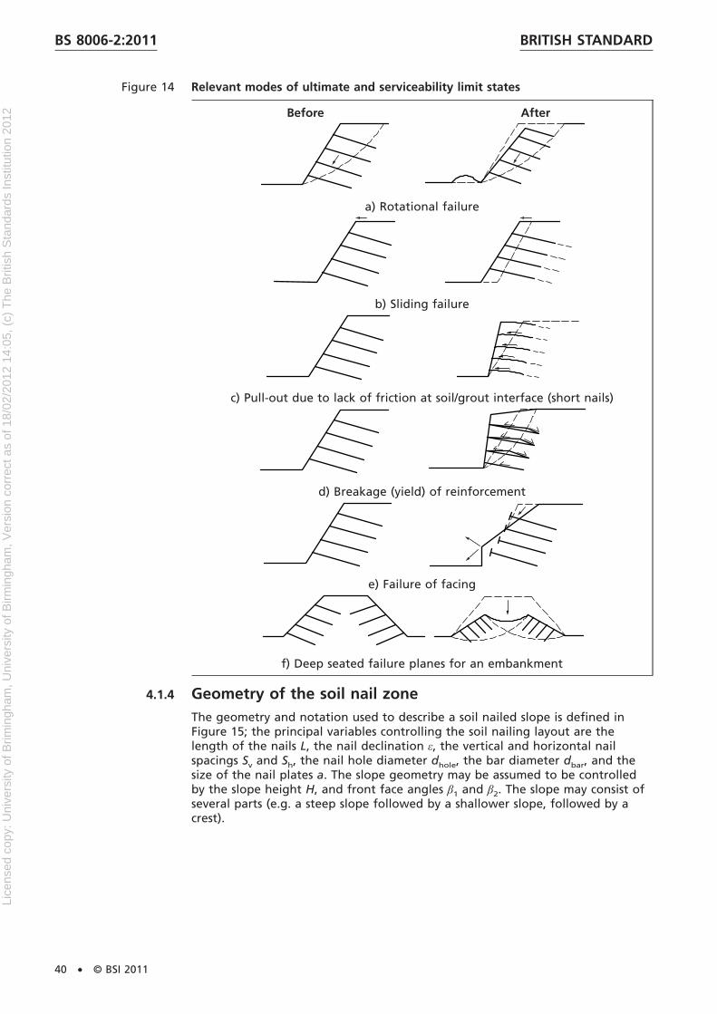
Figure 14 Relevant modes of ultimate and serviceability limit states
Before After
a) Rotational failure
b) Sliding failure
c) Pull-out due to lack of friction at soil/grout interface (short nails)
d) Breakage (yield) of reinforcement
e) Failure of facing
f) Deep seated failure planes for an embankment
4.1.4 Geometry of the soil nail zoneThe geometry and notation used to describe a soil nailed slope is defined inFigure 15; the principal variables controlling the soil nailing layout are thelength of the nails L, the nail declination ε, the vertical and horizontal nailspacings Sv and Sh, the nail hole diameter dhole, the bar diameter dbar, and thesize of the nail plates a. The slope geometry may be assumed to be controlledby the slope height H, and front face angles β1 and β2. The slope may consist ofseveral parts (e.g. a steep slope followed by a shallower slope, followed by acrest).
BRITISH STANDARDBS 8006-2:2011
40 • © BSI 2011
Lice
nsed
cop
y: U
nive
rsity
of B
rimin
gham
, Uni
vers
ity o
f Birm
ingh
am, V
ersi
on c
orre
ct a
s of
18/
02/2
012
14:0
5, (
c) T
he B
ritis
h S
tand
ards
Inst
itutio
n 20
12

4.1.5 Partial factorsIn keeping with BS EN 1997-1:2004 a partial factor approach should be adoptedin order to minimize the risk of a soil nailed structure attaining a limit state.Table 5 summarizes the appropriate partial factors that should be applied toactions, material properties and soil nail resistances; actions are sets of forces orimposed deformations applied to the structure, and can be either favourable orunfavourable.
The design value of an action should be obtained by multiplying therepresentative value by the partial factor. The design value of a materialproperty should be obtained by dividing the characteristic value by the partialfactor. Soil nail resistances arise from the bond stress acting at the interface ofthe nail and the soil, and from the strength of the nail tendon; the design valueof a soil nail resistance should be obtained by dividing the characteristic valuesof bond stress and nail tendon strength by the partial factor.
Table 5 provides two sets of partial factors (1 and 2) and the designer shouldensure that an ultimate limit state will not occur with either set.
NOTE It is assumed that the designer will design the structure for the worstcredible geometry, taking into account the tolerances stated in 2.4.2, therefore nopartial factor relating to geometry is included in Table 5.
The partial factors given in Table 5 do not explicitly take account of whether theworks are of a temporary or permanent nature; this should instead be reflectedin the selection of appropriate characteristic values for the material propertiesand characteristic soil nail resistances.
Figure 15 Geometry and dimensions of a soil nailed slope
Nail length, Lnj = Laj + Lej
BRITISH STANDARD BS 8006-2:2011
© BSI 2011 • 41
Lice
nsed
cop
y: U
nive
rsity
of B
rimin
gham
, Uni
vers
ity o
f Birm
ingh
am, V
ersi
on c
orre
ct a
s of
18/
02/2
012
14:0
5, (
c) T
he B
ritis
h S
tand
ards
Inst
itutio
n 20
12

The characteristic value of a material property should be selected as a cautiousestimate of the value affecting the occurrence of the limit state. Furtherguidance may be found in BS EN 1997-1:2004, 2.4.5.2(10) and 2.4.5.2(11). Therepresentative value of an action should be the characteristic value, or anaccompanying value as defined in BS EN 1990 (all parts).
The selection of a partial factor for an action in Table 1 should depend onwhether the action has a stabilizing effect (favourable) or a destabilizing effect(unfavourable).
In certain situations, where an action may be considered as being bothstabilizing and destabilizing within the same calculation (e.g. soil weightcontributing to both the driving and resisting moments in an effective stressanalysis), only a single partial factor need be applied to that action percalculation. (This is consistent with the Note to BS EN 1997-1:2004, 2.4.2 and isreferred to as the single source principle.)
Pore water pressures should be assumed to be the worst credible under normaloperations, that is to say the most onerous that is considered reasonablypossible during the design lifetime. There may be an element of engineeringjudgement involved in this assessment. Maintenance of drainage schemes (ifany) and the possible risk of their failure should be taken into account.
Where soil nails are being used to remediate a failed slope or where relic shearsurfaces are known to exist, relevant shear strength parameters should be usedon existing failure surfaces, including residual values where appropriate.Alternative partial factors for soil nail design to those given in Table 5 may thenbe considered [this is consistent with BS EN 1997-1:2004, 11.5.1(8)].
Progressive failure should be considered in strain softening, brittle soils (e.g.high plasticity clays).
BRITISH STANDARDBS 8006-2:2011
42 • © BSI 2011
Lice
nsed
cop
y: U
nive
rsity
of B
rimin
gham
, Uni
vers
ity o
f Birm
ingh
am, V
ersi
on c
orre
ct a
s of
18/
02/2
012
14:0
5, (
c) T
he B
ritis
h S
tand
ards
Inst
itutio
n 20
12

Table 5 Partial factors for soil nail design
Design values are to be obtained by multiplying the representative values of the actions, and dividingthe characteristic values of the material properties and soil nail resistances, by the following partialfactors.A)
Set 1 Set 2Actions Self-weight of soil, W dstB) γg = 1.35 γg = 1.0
stbB) γg = 1.0 γg = 1.0Permanent surcharge, qp dst γqp = 1.35 γqp = 1.0
stb γqp = 1.0 γqp = 1.0Variable surcharge, qv dst γqv = 1.5 γqv = 1.3
stb γqv = 0 γqv = 0Ground-water pressure,u
dst γu = 1.0 γu = 1.0stb γu = 1.0 γu = 1.0
Materialproperties
tan φ'k γtanφ' = 1.0 γtanφ' = 1.3c'k γc' = 1.0 γc' = 1.3cuk γcu = 1.0 γcu = 1.4γk γγ = 1.0 γγ = 1.0
Soil nailresistances C)
BondstressD), τbk
Empirical γτb = 1.1 γτb = 1.5Effective stressE) γτb = 1.1 γτb = 1.5Total stressE) γτb = 1.1 γτb = 1.5Pull-out testsF) γτb = 1.1 – 1.7 γτb = 1.5 – 2.25
Tendon strength, Tk γs = 1.0 γs = 1.15 for steelModel factor Applied to the effect of
unfavourable actionsF),G) (e.g. toMdriving in the case of Bishop’s slipcircles)
γSd γSd
A) In the case of abnormal risk or unusual or exceptionally difficult ground or loading conditions (GeotechnicalCategory 3 structures as defined in BS EN 1997-1:2004), all non-unity values in the above table should beincreased by 10%.
B) stb = stabilizing; dst = destabilizing.
C) The factors shown for soil resistances are a summary of the fuller explanation given in Table 6.
D) Refer to 4.3 for appropriate choice of characteristic bond stress to reflect whether nails are temporary orpermanent.
E) Calculated on characteristic soil properties and ignoring qv.
F) See 4.3.6.
G) The values of γSd will be dependent on the calculation method used. γSd may be set to unity forBishop’s simplified method of slices, or for calculations performed with the two-part wedgemechanism assuming a vertical inter-wedge boundary with a friction value not exceeding 0.5φ'. Forother methods of analysis a safe value of γSd should be determined through calibration.
4.2 Analysis of stability
4.2.1 Internal stability
4.2.1.1 General
NOTE Internal stability concerns the assessment of mechanisms which are eitherfully contained within the soil nailed zone or pass through some part of it (the latteris also sometimes referred to as “compound stability”).
BRITISH STANDARD BS 8006-2:2011
© BSI 2011 • 43
Lice
nsed
cop
y: U
nive
rsity
of B
rimin
gham
, Uni
vers
ity o
f Birm
ingh
am, V
ersi
on c
orre
ct a
s of
18/
02/2
012
14:0
5, (
c) T
he B
ritis
h S
tand
ards
Inst
itutio
n 20
12

The design aim should be to arrive at a soil nailing layout and facing design forwhich the factored resisting forces exceed the factored driving forces for anypostulated failure mechanism, both in the short term and the long term and foreach stage of construction. Additionally each nail and facing element should becapable of resisting the local stresses acting on it.
The relevant ULS modes of failure for internal stability analyses should be:
a) rotational failure either partially or totally through the soil nail blockinvolving breakage and/or pull-out of soil nails, and/or failure of the facing,e.g. C, D or H in Figure 16 (4.2.1.2);
b) translational failure (i.e. forward sliding) through the soil-nailed zoneinvolving either breakage and/or pull-out of soil nails, and/or failure of thefacing, e.g. F or I in Figure 16 (4.2.1.3);
c) local overstressing of nails, e.g. K in Figure 16 (4.2.1.4); and
d) local front face failure, e.g. G or L in Figure 16 (4.7).
Figure 16 Ultimate limit state modes of failure
KeyA, B, E External rotational failures
C, D, H Internal rotational failures
F, I Internal translational failures
1 Surface
G, L Internal, local front face failure
J External translational failure
K Internal, local overstressing of nails
2 Soil nails
4.2.1.2 Bishop’s simplified method of slices
NOTE The most common method of limit equilibrium analysis for the purposes ofassessing rotational stability, available in most commercial design software packages,is Bishop’s simplified slip circle method (Bishop [21], Bishop and Morgenstern [22]).
Method: Divide the free body into a number of slices with vertical sides asshown on Figure 17. For Bishop’s simplified method, effectively assume that theinter-slice shear forces are zero (i.e. frictionless and cohesionless) in order for theforces acting on the base of each slice to become determinate.
BRITISH STANDARDBS 8006-2:2011
44 • © BSI 2011
Lice
nsed
cop
y: U
nive
rsity
of B
rimin
gham
, Uni
vers
ity o
f Birm
ingh
am, V
ersi
on c
orre
ct a
s of
18/
02/2
012
14:0
5, (
c) T
he B
ritis
h S
tand
ards
Inst
itutio
n 20
12
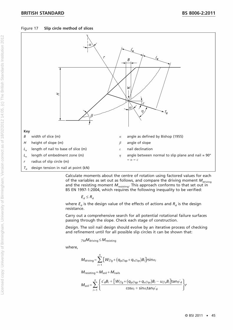
Figure 17 Slip circle method of slices
KeyB width of slice (m)
H height of slope (m)
La length of nail to base of slice (m)
Le length of embedment zone (m)
r radius of slip circle (m)
Td design tension in nail at point (kN)
α angle as defined by Bishop (1955)
β angle of slope
ε nail declination
η angle between normal to slip plane and nail = 90°− α − ε
Calculate moments about the centre of rotation using factored values for eachof the variables as set out as follows, and compare the driving moment Mdriving
and the resisting moment Mresisting. This approach conforms to that set out inBS EN 1997-1:2004, which requires the following inequality to be verified:
Ed ≤ Rd
where Ed is the design value of the effects of actions and Rd is the designresistance.
Carry out a comprehensive search for all potential rotational failure surfacespassing through the slope. Check each stage of construction.
Design. The soil nail design should evolve by an iterative process of checkingand refinement until for all possible slip circles it can be shown that:
γSdMdriving ≤ Mresisting
where,
Mdriving = ∑i51
n
fWiγg + (qpiγqp + qviγqv)Bigrsinαi
Mresisting = Msoil + Mnails
Msoil = ∑i51
n Hc'dBi 1 fWiγg + (qpiγqp + qviγqv)Bi 2 uiγuBigtanφ'
d
cosαi 1 sinαitanφ'd
Jr
BRITISH STANDARD BS 8006-2:2011
© BSI 2011 • 45
Lice
nsed
cop
y: U
nive
rsity
of B
rimin
gham
, Uni
vers
ity o
f Birm
ingh
am, V
ersi
on c
orre
ct a
s of
18/
02/2
012
14:0
5, (
c) T
he B
ritis
h S
tand
ards
Inst
itutio
n 20
12
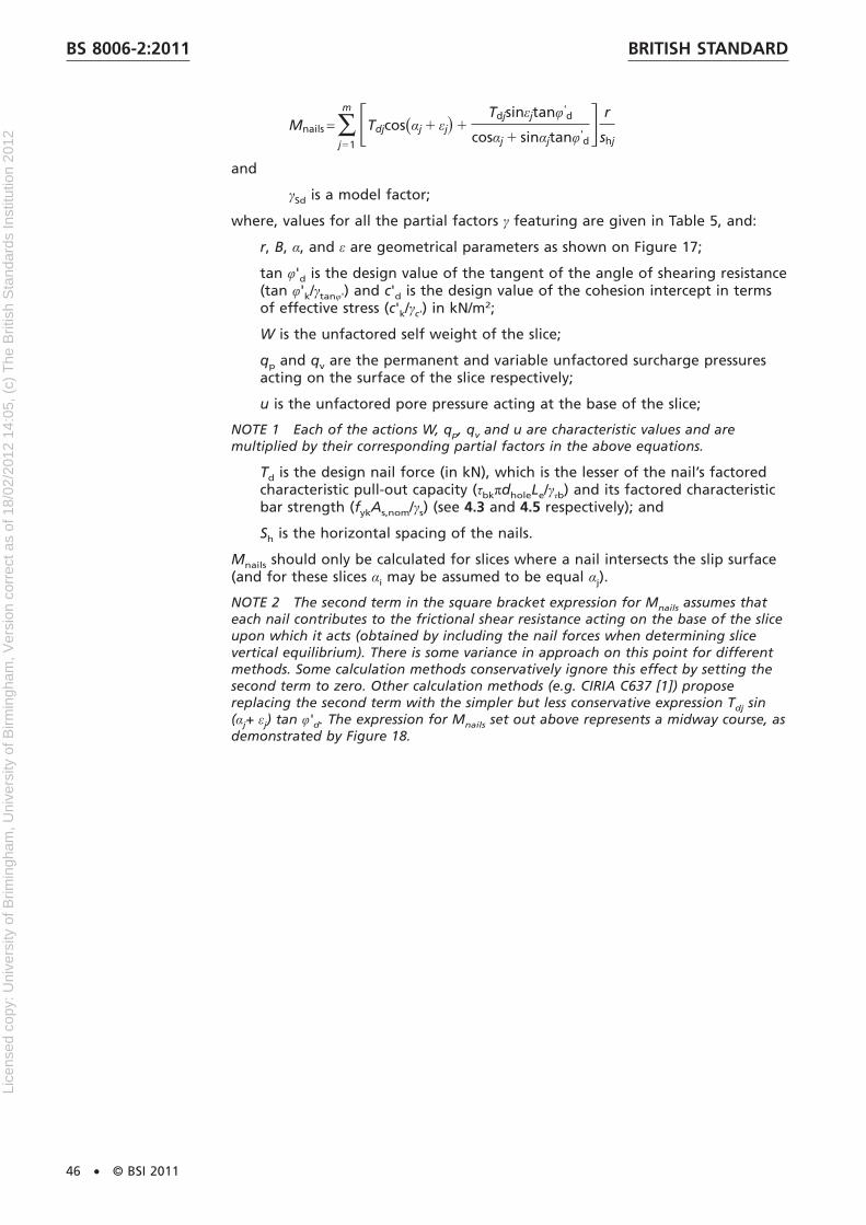
Mnails = ∑j51
m FTdjcos(αj 1 εj� 1Tdjsinεjtanφ'
d
cosαj 1 sinαjtanφ'dG r
shj
and
γSd is a model factor;
where, values for all the partial factors γ featuring are given in Table 5, and:
r, B, α, and ε are geometrical parameters as shown on Figure 17;
tan φ'd is the design value of the tangent of the angle of shearing resistance(tan φ'k/γtanφ') and c'd is the design value of the cohesion intercept in termsof effective stress (c'k/γc') in kN/m2;
W is the unfactored self weight of the slice;
qp and qv are the permanent and variable unfactored surcharge pressuresacting on the surface of the slice respectively;
u is the unfactored pore pressure acting at the base of the slice;
NOTE 1 Each of the actions W, qp, qv and u are characteristic values and aremultiplied by their corresponding partial factors in the above equations.
Td is the design nail force (in kN), which is the lesser of the nail’s factoredcharacteristic pull-out capacity (τbkπdholeLe/γτb) and its factored characteristicbar strength (fykAs,nom/γs) (see 4.3 and 4.5 respectively); and
Sh is the horizontal spacing of the nails.
Mnails should only be calculated for slices where a nail intersects the slip surface(and for these slices αi may be assumed to be equal αj).
NOTE 2 The second term in the square bracket expression for Mnails assumes thateach nail contributes to the frictional shear resistance acting on the base of the sliceupon which it acts (obtained by including the nail forces when determining slicevertical equilibrium). There is some variance in approach on this point for differentmethods. Some calculation methods conservatively ignore this effect by setting thesecond term to zero. Other calculation methods (e.g. CIRIA C637 [1]) proposereplacing the second term with the simpler but less conservative expression Tdj sin(αj+ εj) tan φ'd. The expression for Mnails set out above represents a midway course, asdemonstrated by Figure 18.
BRITISH STANDARDBS 8006-2:2011
46 • © BSI 2011
Lice
nsed
cop
y: U
nive
rsity
of B
rimin
gham
, Uni
vers
ity o
f Birm
ingh
am, V
ersi
on c
orre
ct a
s of
18/
02/2
012
14:0
5, (
c) T
he B
ritis
h S
tand
ards
Inst
itutio
n 20
12
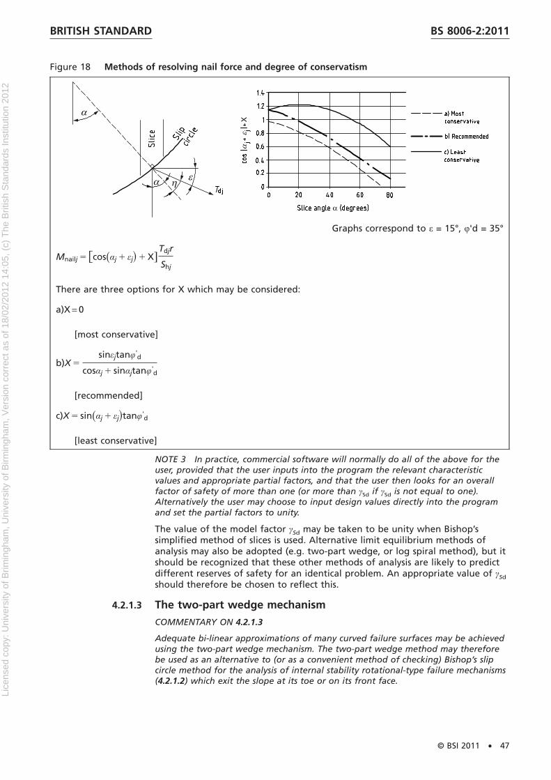
Figure 18 Methods of resolving nail force and degree of conservatism
Graphs correspond to ε = 15°, φ'd = 35°
Mnailj 5 fcos(αj 1 εj� 1 X]Tdjr
Shj
There are three options for X which may be considered:
a)X = 0
[most conservative]
b)X 5sinεjtanφ'
d
cosαj 1 sinαjtanφ'd
[recommended]
c)X 5 sin(αj 1 εj�tanφ'd
[least conservative]
NOTE 3 In practice, commercial software will normally do all of the above for theuser, provided that the user inputs into the program the relevant characteristicvalues and appropriate partial factors, and that the user then looks for an overallfactor of safety of more than one (or more than γSd if γSd is not equal to one).Alternatively the user may choose to input design values directly into the programand set the partial factors to unity.
The value of the model factor γSd may be taken to be unity when Bishop’ssimplified method of slices is used. Alternative limit equilibrium methods ofanalysis may also be adopted (e.g. two-part wedge, or log spiral method), but itshould be recognized that these other methods of analysis are likely to predictdifferent reserves of safety for an identical problem. An appropriate value of γSd
should therefore be chosen to reflect this.
4.2.1.3 The two-part wedge mechanism
COMMENTARY ON 4.2.1.3
Adequate bi-linear approximations of many curved failure surfaces may be achievedusing the two-part wedge mechanism. The two-part wedge method may thereforebe used as an alternative to (or as a convenient method of checking) Bishop’s slipcircle method for the analysis of internal stability rotational-type failure mechanisms(4.2.1.2) which exit the slope at its toe or on its front face.
BRITISH STANDARD BS 8006-2:2011
© BSI 2011 • 47
Lice
nsed
cop
y: U
nive
rsity
of B
rimin
gham
, Uni
vers
ity o
f Birm
ingh
am, V
ersi
on c
orre
ct a
s of
18/
02/2
012
14:0
5, (
c) T
he B
ritis
h S
tand
ards
Inst
itutio
n 20
12

The two-part wedge mechanism involves less calculation than Bishop’s method ofslices. It is therefore simpler to use and may be readily formulated using a desk-topspreadsheet program. It has the advantage of being fully explicit and thecalculations performed being reassuringly understandable.
The two-part wedge is also particularly well suited to analysing forward slidingacross a planar surface. It cannot however be used to analyse deep seated rotationalfailures which outcrop beyond the toe of the slope.
Method. Examine the stability of each mechanism in terms of a force balanceacross the inter-wedge boundary, rather than a moment balance as used earlierfor Bishop’s slip circles; the principal requirement is that the factored resistingforce provided by the lower wedge normal to the interwedge boundary exceedsthe factored driving force from the upper wedge.
Using geometry and variables defined in Figure 19, take the inter-wedgeboundary as vertical and having a reduced inter-wedge friction angle comparedto the parent soil (typically half or less, zero being the simplest assumption).
Design. The following simple inequality should be satisfied by the design:
γSdN21 ≤ N12
where
N21 =H(W1γg + Qp1γqp + Qv1γqv)(sinθ1 − cosθ1tanφ'd1)
cosθ1 + sinθ1tanφ'd1
J+
5−F∑ Td1
ShG[cos(θ1 + ε� 1 sin(θ1 + ε�tanφ'
d1] + U1tanφ'd1 − Kd1
cosθ1 + sinθ1tanφ'd1
6N12 =H−(W2γg + Qp2γqp + Qv2γqv)(sinθ2 − cosθ2tanφ'
d2)cosθ2 + sinθ2tanφ'
d2J+
5F∑Td2
ShG[cos(θ2 + ε� 1 sin(θ2 + ε�tanφ'
d2] − U2tanφ'd2 − Kd2
cosθ2 + sinθ2tanφ'd2
6NOTE These equations correspond to the simplified case of zero friction on theinter-wedge boundary. Equations describing the more general case of a non-zerofriction on the inter-wedge boundary may be found in HA68/94 [23] Appendix A(para A7).
At the time of publication it is not thought that there has been a comprehensivestudy comparing the two-part wedge method and Bishop’s simple method of slicesfor soil nailed slopes incorporating different inter-wedge friction angles andinclinations. Some useful general guidance is provided in Appendix A of HA68/94[23] on the effect of inter-wedge friction angle.
The assumption of a frictionless inter-wedge boundary is always likely to beconservative compared to Bishop’s simple method of slices (and will also simplify theequations), while the assumption of full friction on the inter-wedge boundary isalways likely to be unconservative.
The value of the model factor γSd may be taken as unity for two-part wedgemechanisms adopting a vertical inter-wedge boundary with an inter-wedgefriction angle not exceeding 0.5φ' (see Table 5). Two-part wedge mechanismswith a non-vertical inter-wedge boundary may also be considered, for examplealigning with the rear of the soil nailed zone and mobilizing full friction.However such designs are unlikely to have the same reserve of safety as thenormal method and an appropriately higher value of γSd should be adopted forsuch cases.
BRITISH STANDARDBS 8006-2:2011
48 • © BSI 2011
Lice
nsed
cop
y: U
nive
rsity
of B
rimin
gham
, Uni
vers
ity o
f Birm
ingh
am, V
ersi
on c
orre
ct a
s of
18/
02/2
012
14:0
5, (
c) T
he B
ritis
h S
tand
ards
Inst
itutio
n 20
12
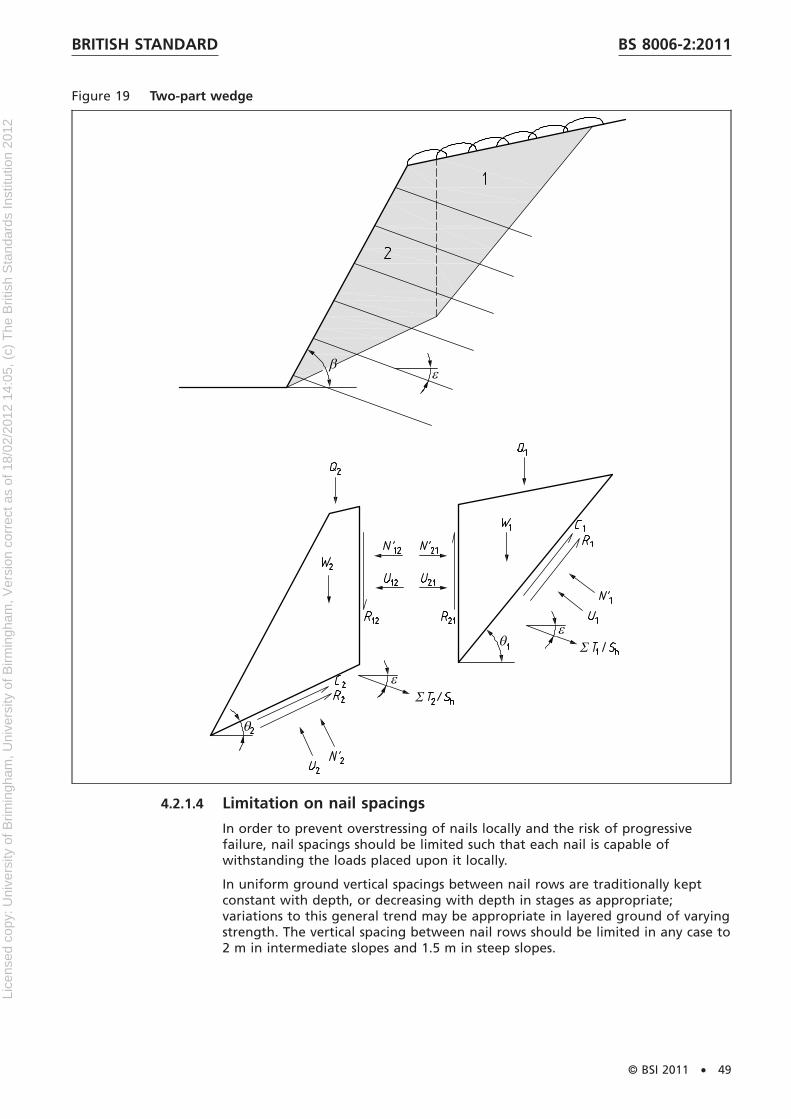
Figure 19 Two-part wedge
4.2.1.4 Limitation on nail spacings
In order to prevent overstressing of nails locally and the risk of progressivefailure, nail spacings should be limited such that each nail is capable ofwithstanding the loads placed upon it locally.
In uniform ground vertical spacings between nail rows are traditionally keptconstant with depth, or decreasing with depth in stages as appropriate;variations to this general trend may be appropriate in layered ground of varyingstrength. The vertical spacing between nail rows should be limited in any case to2 m in intermediate slopes and 1.5 m in steep slopes.
BRITISH STANDARD BS 8006-2:2011
© BSI 2011 • 49
Lice
nsed
cop
y: U
nive
rsity
of B
rimin
gham
, Uni
vers
ity o
f Birm
ingh
am, V
ersi
on c
orre
ct a
s of
18/
02/2
012
14:0
5, (
c) T
he B
ritis
h S
tand
ards
Inst
itutio
n 20
12

NOTE If performed thoroughly the upper bound methods described in 4.2.1.2 and4.2.1.3 ought on their own to be sufficient to ensure that vertical spacings betweennail rows are not excessive and that each row of nails is able to withstand the loadsplaced upon it. This is because these methods will (or ought to) include, within theircomprehensive search of slip circles (or two-part wedge, or other chosenmechanism), mechanisms which daylight on the front face just above each nail row.
An alternative method that may be adopted to ensure that each row of nails isable to withstand the loads placed upon it locally is to adopt a lower bound“stress state” approach (as for example embodied in HA68/94 [23]). According tothis approach, the maximum nail spacing at any point may determined by theexpression:
Sv =Td
KγzSh
where
Td is the design nail strength (in kN);
K is the earth pressure co-efficient in terms of total stress and factored soilstrength (refer to HA 68/94 [23] for evaluation);
γ is the weight density (in kN/m3);
z is the depth to mid-point between the row of nails in question and thenext row below (m);
Sv, Sh are the vertical and horizontal nail spacings (m).
4.2.2 External stability
4.2.2.1 General
COMMENTARY ON 4.2.2.1
External stability analysis concerns the assessment of mechanisms which affect thestability of the soil nail zone but do not intersect it at any point (also referred to as“global stability”).
The relevant ULS modes of failure for external stability analyses should be:
a) deep seated rotational failure, e.g. A or B in Figure 16; and
b) translational failure (i.e. forward sliding) beneath the soil nail zone, e.g. J inFigure 16.
From an analytical point of view the external stability check for deep seatedrotational failure may simply be seen as an extension to the internal stabilitycheck (4.2.1.2) except that no nail forces are involved. Similarly, the externalstability check for translational failure (i.e. forward sliding) may be seen as anextension to the internal stability check (4.2.1.3).
The same methods of analysis described in 4.2.1.2 and 4.2.1.3 may therefore beemployed for these external stability checks.
While there is little or no distinction from an analytical point of view betweeninternal and external stability, an important distinction may be madecontractually between the two if different parties are responsible for externaland internal stability.
If there is an upper slope above the nailed slope then the stability of this slopeshould also be checked (e.g. E in Figure 16).
BRITISH STANDARDBS 8006-2:2011
50 • © BSI 2011
Lice
nsed
cop
y: U
nive
rsity
of B
rimin
gham
, Uni
vers
ity o
f Birm
ingh
am, V
ersi
on c
orre
ct a
s of
18/
02/2
012
14:0
5, (
c) T
he B
ritis
h S
tand
ards
Inst
itutio
n 20
12

4.2.2.2 Additional methods of analysing external stability for near verticalsoil nailed slopes
NOTE Traditionally it has been a requirement to check soil nailed slopes forexternal stability as if they were gravity retaining walls or reinforced earthstructures. Recommended checks have included bearing capacity, forward sliding andoverturning.
In reality the soil nail zone does not act as a rigid block, nor do discrete soilboundaries normally exist either behind the soil nail zone or below it: the frontfacing can be soft or flexible, the soil is generally continuous, the nails arenormally inclined downwards and represent individual 3-D inclusions rather than2-D layers; consequently soil nailed slopes fit more naturally into slope stabilityphilosophy and should be analysed as such, using the methods described above.
In certain circumstances however (e.g. near vertical slopes with hard facings) itmay be appropriate additionally to carry out the traditional lower boundexternal stability checks for bearing capacity, forward sliding and overturning,treating the soil nailed zone as if it were a gravity retaining wall structure. Inthis instance the procedures set out in BS 8006-1:2010, 6.5 should be followed.
An indication of whether such checks are likely to be necessary or not will begiven by the upper bound methods described in 4.2.2.1:
a) potential bearing capacity issues are likely to be indicated by a properlyperformed slip circle analysis;
b) potential forward sliding issues are likely to be indicated by a properlyperformed two-part wedge analysis.
4.3 Soil nail pullout resistanceCOMMENTARY ON 4.3
Provided the nail tendon is sufficiently strong, then as relative movement occursbetween the soil nail and the ground shear stresses will be mobilized between thesurface of the nail and the ground. The relative movement will be different withinthe active and passive zones of a soil nailed application (Figure 20). This stress isknown as bond stress and it has a limiting value, dependent upon a number offactors as described in 4.3.1, 4.3.2 and 4.3.3.
When the limiting value of bond stress is reached the nail will pull out of theground or bond failure will occur. For calculation purposes it is convenient toestablish a nail strength “envelope” for each nail in the slope by taking into accountthe limiting bond stress available at any point along the nail, the tendon strength Rt
(see 4.5) and the nail head force at the front face of the slope (Tf, 4.2.1.4), Figure 21.
From the nail strength envelope it is then simple to establish the tension in the nailat the point at which an assumed failure surface from the stability assessmentcrosses the nail.
BRITISH STANDARD BS 8006-2:2011
© BSI 2011 • 51
Lice
nsed
cop
y: U
nive
rsity
of B
rimin
gham
, Uni
vers
ity o
f Birm
ingh
am, V
ersi
on c
orre
ct a
s of
18/
02/2
012
14:0
5, (
c) T
he B
ritis
h S
tand
ards
Inst
itutio
n 20
12
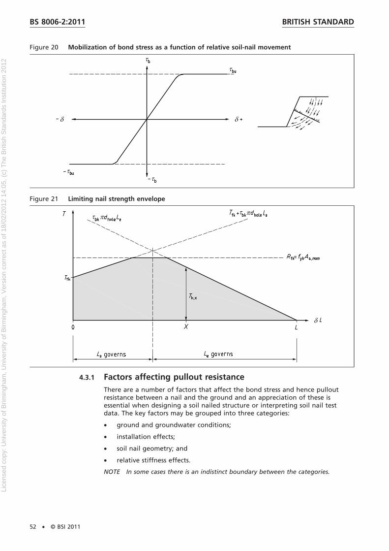
Figure 20 Mobilization of bond stress as a function of relative soil-nail movement
Figure 21 Limiting nail strength envelope
4.3.1 Factors affecting pullout resistanceThere are a number of factors that affect the bond stress and hence pulloutresistance between a nail and the ground and an appreciation of these isessential when designing a soil nailed structure or interpreting soil nail testdata. The key factors may be grouped into three categories:
• ground and groundwater conditions;
• installation effects;
• soil nail geometry; and
• relative stiffness effects.
NOTE In some cases there is an indistinct boundary between the categories.
BRITISH STANDARDBS 8006-2:2011
52 • © BSI 2011
Lice
nsed
cop
y: U
nive
rsity
of B
rimin
gham
, Uni
vers
ity o
f Birm
ingh
am, V
ersi
on c
orre
ct a
s of
18/
02/2
012
14:0
5, (
c) T
he B
ritis
h S
tand
ards
Inst
itutio
n 20
12
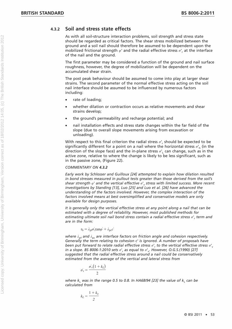
4.3.2 Soil and stress state effectsAs with all soil-structure interaction problems, soil strength and stress stateshould be regarded as critical factors. The shear stress mobilized between theground and a soil nail should therefore be assumed to be dependent upon themobilized frictional strength φ' and the radial effective stress σ'r at the interfaceof the nail and the ground.
The first parameter may be considered a function of the ground and nail surfaceroughness, however, the degree of mobilization will be dependent on theaccumulated shear strain.
The post peak behaviour should be assumed to come into play at larger shearstrains. The second parameter of the normal effective stress acting on the soilnail interface should be assumed to be influenced by numerous factorsincluding:
• rate of loading;
• whether dilation or contraction occurs as relative movements and shearstrains develop;
• the ground’s permeability and recharge potential; and
• nail installation effects and stress state changes within the far field of theslope (due to overall slope movements arising from excavation orunloading).
With respect to this final criterion the radial stress σ'r should be expected to besignificantly different for a point on a nail where the horizontal stress σ'h (in thedirection of the slope face) and the in-plane stress σ'L can change, such as in theactive zone, relative to where the change is likely to be less significant, such asin the passive zone, (Figure 22).
COMMENTARY ON 4.3.2
Early work by Schlosser and Guilloux [24] attempted to explain how dilation resultedin bond stresses measured in pullout tests greater than those derived from the soil’sshear strength φ' and the vertical effective σ'v stress with limited success. More recentinvestigations by Standing [13], Luo [25] and Luo et al. [26] have advanced theunderstanding of the factors involved. However, the complex interaction of thefactors involved means at best oversimplified and conservative models are onlyavailable for design purposes.
It is generally only the vertical effective stress at any point along a nail that can beestimated with a degree of reliability. However, most published methods forestimating ultimate soil nail bond stress contain a radial effective stress σ'r term andare in the form:
τb 5 λpfσ'rtanφ' 1 λpcc'
where λpf and λpc are interface factors on friction angle and cohesion respectively.Generally the term relating to cohesion c' is ignored. A number of proposals havebeen put forward to relate radial effective stress σ'r to the vertical effective stress σ'vin a slope. BS 8006-1:2010 sets σ'r as equal to σ'v. However, O.G.S.(1990) [27]suggested that the radial effective stress around a nail could be conservativelyestimated from the average of the vertical and lateral stress from
σ'r 5
σ'vs1 1 kLd
2
where kL was in the range 0.5 to 0.8. In HA68/94 [23] the value of kL can becalculated from
kL 51 1 ka
2
BRITISH STANDARD BS 8006-2:2011
© BSI 2011 • 53
Lice
nsed
cop
y: U
nive
rsity
of B
rimin
gham
, Uni
vers
ity o
f Birm
ingh
am, V
ersi
on c
orre
ct a
s of
18/
02/2
012
14:0
5, (
c) T
he B
ritis
h S
tand
ards
Inst
itutio
n 20
12
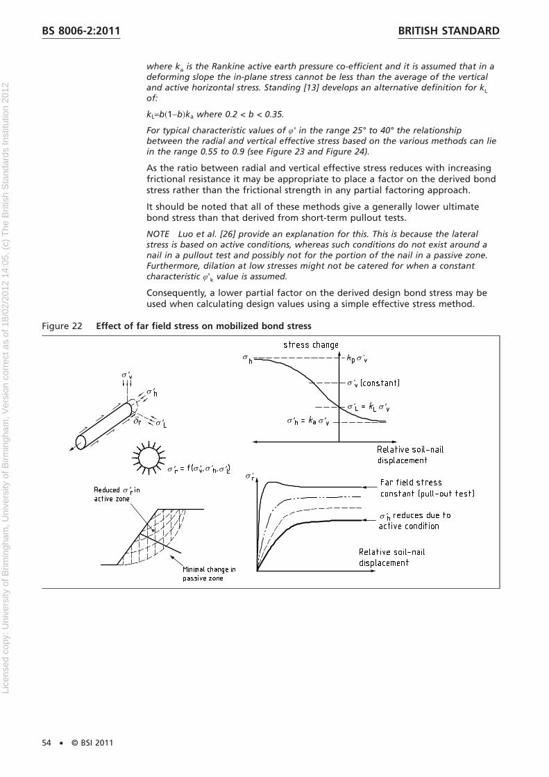
where ka is the Rankine active earth pressure co-efficient and it is assumed that in adeforming slope the in-plane stress cannot be less than the average of the verticaland active horizontal stress. Standing [13] develops an alternative definition for kL
of:
kL=b�1−b�ka where 0.2 < b < 0.35.
For typical characteristic values of φ' in the range 25° to 40° the relationshipbetween the radial and vertical effective stress based on the various methods can liein the range 0.55 to 0.9 (see Figure 23 and Figure 24).
As the ratio between radial and vertical effective stress reduces with increasingfrictional resistance it may be appropriate to place a factor on the derived bondstress rather than the frictional strength in any partial factoring approach.
It should be noted that all of these methods give a generally lower ultimatebond stress than that derived from short-term pullout tests.
NOTE Luo et al. [26] provide an explanation for this. This is because the lateralstress is based on active conditions, whereas such conditions do not exist around anail in a pullout test and possibly not for the portion of the nail in a passive zone.Furthermore, dilation at low stresses might not be catered for when a constantcharacteristic φ'k value is assumed.
Consequently, a lower partial factor on the derived design bond stress may beused when calculating design values using a simple effective stress method.
Figure 22 Effect of far field stress on mobilized bond stress
BRITISH STANDARDBS 8006-2:2011
54 • © BSI 2011
Lice
nsed
cop
y: U
nive
rsity
of B
rimin
gham
, Uni
vers
ity o
f Birm
ingh
am, V
ersi
on c
orre
ct a
s of
18/
02/2
012
14:0
5, (
c) T
he B
ritis
h S
tand
ards
Inst
itutio
n 20
12

Figure 23 Modification of interface stresses due to far field stress changes
Figure 24 Relationships between radial friction normalized by vertical effective stress for a range ofcharacteristic friction angle
BRITISH STANDARD BS 8006-2:2011
© BSI 2011 • 55
Lice
nsed
cop
y: U
nive
rsity
of B
rimin
gham
, Uni
vers
ity o
f Birm
ingh
am, V
ersi
on c
orre
ct a
s of
18/
02/2
012
14:0
5, (
c) T
he B
ritis
h S
tand
ards
Inst
itutio
n 20
12

4.3.3 Effect of nail construction methodThere are numerous methods of installing soil nails that should be considered,some of which will result in local stress increases and others in reductions inlocal stresses (see Figure 25). Generally methods that involve driving the nail intothe ground may be expected to increase the stress locally around the nail.Drilled methods may be assumed to result in some reduction of stress, however,the actual magnitude will be dependent on the duration the nail bore remainsopen, the diameter of the bore and whether radial arching maintains stresseslocally, whether casing is used, and whether during nail grouting initial stressesare reinstated or possibly exceeded.
In addition to changes in stress the mechanical effects of soil nail installationshould be considered as to whether smearing of the borehole can occur,whether the borehole is smooth or rough, whether groundwater could result insoftening and whether flushing media such as air or foam could result inclogging of natural pores or fissures. Installation methods that ensure a highdegree of mechanical interlock should be encouraged.
NOTE Chu and Yin [28] report on a laboratory study investigating nail installationand grouting effects.
As the method of installation is likely to have an effect on the final pulloutresistance then care should be taken when comparing the results of nail tests insimilar ground to ensure the installation processes are understood.
Figure 25 Modification of local interface stresses due to nail installation effects
NOTE Changes in far field stress ignored.
4.3.4 Soil nail geometry and tendon stiffnessCOMMENTARY ON 4.3.4
The peak bond stress measured during a pullout test in a given soil will varydepending on both nail diameter D and the length of the test section Lbt. Theformer effect is believed to be due to arching of stresses around the soil nail, wherethe ability for arching to occur is greater for smaller diameters than for largerdiameters. Luo et al. [26] have proposed a model that takes this effect into accountand which provides a good fit to experimental data. This observation is consistentwith frictional data from ground anchors, minipiles and bored piles in similar groundwhere lower shaft friction is generally noted for larger diameters.
In addition to nail diameter D, the length of the nail being pulled out of theground also has an effect that should be taken into consideration. Generallyshorter test bond lengths should be expected to result in a higher averagemobilized bond stress than for longer bond lengths.
BRITISH STANDARDBS 8006-2:2011
56 • © BSI 2011
Lice
nsed
cop
y: U
nive
rsity
of B
rimin
gham
, Uni
vers
ity o
f Birm
ingh
am, V
ersi
on c
orre
ct a
s of
18/
02/2
012
14:0
5, (
c) T
he B
ritis
h S
tand
ards
Inst
itutio
n 20
12
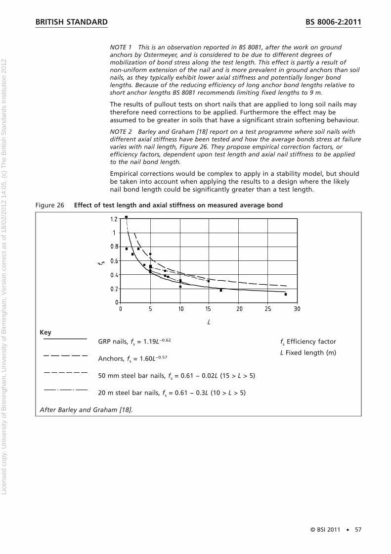
NOTE 1 This is an observation reported in BS 8081, after the work on groundanchors by Ostermeyer, and is considered to be due to different degrees ofmobilization of bond stress along the test length. This effect is partly a result ofnon-uniform extension of the nail and is more prevalent in ground anchors than soilnails, as they typically exhibit lower axial stiffness and potentially longer bondlengths. Because of the reducing efficiency of long anchor bond lengths relative toshort anchor lengths BS 8081 recommends limiting fixed lengths to 9 m.
The results of pullout tests on short nails that are applied to long soil nails maytherefore need corrections to be applied. Furthermore the effect may beassumed to be greater in soils that have a significant strain softening behaviour.
NOTE 2 Barley and Graham [18] report on a test programme where soil nails withdifferent axial stiffness have been tested and how the average bonds stress at failurevaries with nail length, Figure 26. They propose empirical correction factors, orefficiency factors, dependent upon test length and axial nail stiffness to be appliedto the nail bond length.
Empirical corrections would be complex to apply in a stability model, but shouldbe taken into account when applying the results to a design where the likelynail bond length could be significantly greater than a test length.
Figure 26 Effect of test length and axial stiffness on measured average bond
KeyGRP nails, fs = 1.19L−0.62 fs Efficiency factor
L Fixed length (m)Anchors, fs = 1.60L−0.57
50 mm steel bar nails, fs = 0.61 − 0.02L (15 > L > 5)
20 m steel bar nails, fs = 0.61 − 0.3L (10 > L > 5)
After Barley and Graham [18].
BRITISH STANDARD BS 8006-2:2011
© BSI 2011 • 57
Lice
nsed
cop
y: U
nive
rsity
of B
rimin
gham
, Uni
vers
ity o
f Birm
ingh
am, V
ersi
on c
orre
ct a
s of
18/
02/2
012
14:0
5, (
c) T
he B
ritis
h S
tand
ards
Inst
itutio
n 20
12
4.3.5 Methods of assessing ultimate bond stress or soil nail pulloutresistanceCOMMENTARY ON 4.3.5
There is a range of methods by which soil nail ultimate pullout resistance or ultimatebond stress can be assessed. During the project design phase it is likely that aselection of approaches will be followed with a greater emphasis on empirical dataat an early design stage. As knowledge of the ground conditions and parametersimproves the option of using an analytical approach may arise, but it is notuncommon to develop a design on the basis of empirical data, that is subsequentlyvalidated by pre or post construction pullout tests. The designer in all cases will needto assess the degree of certainty that can be relied upon by any particular method.The options for assessing a characteristic design bond stress or pullout resistance aredescribed below.
4.3.5.1 Assessment of ultimate bond stress by empirical approaches
NOTE It is common practice in soil nail design to employ empirical data whenassessing the ultimate bond stress τb or pullout resistance Tb. Published guidancesuch as CIRIA C637 [1], FHWA [20] and BS 8081 provide an indication of characteristicbond stresses achieved in a range of soils and rocks for a variety of nail installationmethods and diameters. The critical issue when using such data is in theunderstanding of the degree to which they can be relied upon in the newapplication.
Relative to the design being undertaken, the designer should challenge thesimilarity of the ground conditions, the nail installation method, the details ofthe test and test procedure, nail diameter, test length, the number of tests, thesimilarity of the design application and the proposed validation process.
The ultimate bond stress or bond force that may be derived by an empiricalapproach is denoted as τb,ue or Tb,ue with respective units kN/m2 and kN/m(length of nail). The characteristic and design bond resistances for use in theanalysis may be derived from the ultimate empirical values as described in 4.3.6.
Other methods of determining ultimate bond values from empirical correlationswith soil tests, such as that proposed in Clouterre [19] for the MenardPressuremeter should be treated in the same manner as direct empiricalassessment from pullout test data as above.
4.3.5.2 Ultimate bond stress derived from effective stress methods
As discussed in 4.3.1 the state of stress acting around a nail is complexdepending on the degree of slope movement and nail installation method; forsimplicity the ultimate bond stress should be taken as the characteristic bondstress and calculated from the vertical effective stress and characteristic soilshear strength from:
where λf is an interface factor dependent upon the nail installation method andkr is a factor relating the average radial effective stress around the nail to thevertical and has a value typically in the range 0.55 to 0.9, depending on therelative density of the soil and degree of stress reduction due to slopemovements in the active zone of the slope.
NOTE This has an implication on the type of facing used.
The interface factor λf should be taken to be between 0.7 and 1.0 with thelower value relating to smooth interfaces and the higher value relating to roughinterfaces.
Effective stress assessment of ultimate bond stress τbu tends to give low valueswhen compared with pullout test results as it is based on a reduced stress statein the active zone and this should be acknowledged when assessing thecharacteristic bond stress τbk by employing a partial factor of 1.0.
BRITISH STANDARDBS 8006-2:2011
58 • © BSI 2011
Lice
nsed
cop
y: U
nive
rsity
of B
rimin
gham
, Uni
vers
ity o
f Birm
ingh
am, V
ersi
on c
orre
ct a
s of
18/
02/2
012
14:0
5, (
c) T
he B
ritis
h S
tand
ards
Inst
itutio
n 20
12

4.3.5.3 Ultimate bond stress derived from total stress method
This method is analogous to the method used to derive shaft friction in piledesign and relates the characteristic bond stress to the undrained shear strengthcu of the ground using an “alpha” coefficient.
τbu = αcu
The value of the coefficient α lies in the range 0.3 to 0.6 for bored piles,however, if based on the efficiency factor proposed for anchors by Barley andGraham [18] is likely to be in the range 0.5 to 0.9 for bond lengths ranging from7 m to 3 m.
It should be noted that the ultimate bond stress determined by this method isrelatively high when compared with the effective stress method. Furthermore, inhigh plasticity soils where a large difference occurs between peak and residualshear strength, consideration should be given to overall slope displacement andthe likelihood of residual strengths being mobilized. Consequently a higherdegree of conservatism should be used when deriving characteristic bondstresses from total stress shear strengths.
4.3.5.4 Ultimate bond stress from pullout tests
Subclause 6.2 provides details of pullout tests that may be used in the executionof soil nailing. Design investigation and suitability soil nail pullout tests shouldbe used to determine ultimate bond stresses for design or design verificationrespectively.
For UK applications the maintained load test method as detailed inBS EN 14490:2010 is recommended as the CRP test is relatively difficult to controland has a tendency to overestimate pullout resistance.
The characteristic bond stress τbk should be based on a cautious estimatethrough consideration of the number, location and consistency of the testresults. Unless justified by an appropriate number of tests, then a reductionfactor of between 1.1 and 1.3 should be applied to the average or 1.0 to 1.1 tothe lowest result (see 6.2.4).
NOTE Derivation of the design value from pullout tests is detailed in 4.3.6.
4.3.6 Derivation of design bond strengthSubclauses 4.3.1 to 4.3.5 detail some of the factors that should be considered inthe derivation of ultimate and characteristic bond resistances. Table 6 sets outthe approach that should be followed to derive design values to be utilized inany ULS assessment of stability of a soil nailed structure or slope.
NOTE 1 Unique partial factors, applicable to all methods for deriving thecharacteristic and bond resistances, are not given but rather method specific ranges.This is necessary because a level of knowledge of the implication of how theultimate bond resistance has been derived is necessary along with an understandingof the ground conditions, rates of loading, etc.
NOTE 2 The values in Table 6 have been selected to result in equivalent experiencewith lumped factors of between 1.5 and 3.0 on ultimate bond resistances (andmicropile/ground anchor designs). The range given for γk is to reflect whether nailsare used in a temporary or permanent application and the degree to which fulldissipation of pore pressure is relevant.
As a range of values is given, the designer should consider the criticality of thedesign bond stress in the overall limit equilibrium model, brittleness of bondfailure and the degree of validation specified.
BRITISH STANDARD BS 8006-2:2011
© BSI 2011 • 59
Lice
nsed
cop
y: U
nive
rsity
of B
rimin
gham
, Uni
vers
ity o
f Birm
ingh
am, V
ersi
on c
orre
ct a
s of
18/
02/2
012
14:0
5, (
c) T
he B
ritis
h S
tand
ards
Inst
itutio
n 20
12

Table 6 Ultimate limit state approach to deriving design values
Method ofdeterminingultimate bondstress,τbu
Factors for determiningcharacteristic bond stress fromultimate valuesτbk = τbu /γk
Factors fordetermining designbond stress fromcharacteristic valuesfor set 1,τbd = τbk /γτb
Factors for determiningdesign bond stress fromcharacteristic values forset 2,τbd = τbk /γτb
Empirical pullouttest data
γk = 1.35 to 2.0
Selected value to be based ondegree of confidence relativeto proposed structure, soils,construction method, etc.
γτb = 1.11 γτb = 1.50
Effective stress
NOTE τbu derivedfrom characteristicφ' )
γk = 1.0 to 1.35
Selected value to account forpotential for dilation anddegree slope deformation inactive zone
γτb = 1.11 γτb = 1.50
Total stress
NOTE τbu derivedfrom characteristiccu.
γk = 1.35 to 2.0selected value to account forpotential for strain softening,plasticity and shrink swelleffects
γτb = 1.11 γτb = 1.50
Pullout tests See BS EN 14490:2010Characteristic selected as acautious estimate of the testdata, taking into account thenumber of test results,location and consistency.
γτb = 1.1 to 1.3 forcoarse grained soils
γτb = 1.5 to 1.7 formedium and highplasticity soils
γτb = 1.5 to 1.7 for coarsegrained soils
γτb = 2.0 to 2.25 formedium and highplasticity soils
4.4 Numerical analysisNumerical methods may be used in the design of soil nail structures or specificcomponents. They may be used to provide a clearer understanding ofsoil-structure interaction, deformations and collapse mechanisms in complexgeological or geometric situations. Their use is widespread in geotechnical andstructural engineering and provided appropriate expertise and comparableexperience is used then reliable predictions and assessments of performance canbe achieved.
Soil nail structures are generally complex and involve a variety of structuralelements with varying material properties. Furthermore, construction sequencesoften involve 3-dimensional geometric changes all likely to result in challengingchanges in stress and strain states. It is unlikely that a single numerical methodwill be able to provide an optimum analysis of a soil nail structure in its entiretyand therefore it may be necessary to analyse components separately.
The choice of numerical method employed should take into account:
• the nature of the ground conditions;
• the interaction of structural components with the ground;
• compatibility of strains at the limit state being investigated;
• the sensitivity of the model to small changes in geometry duringconstruction;
• previous or comparable experience and calibration of the numerical methodor constitutive model in the situation to which it is being used;
BRITISH STANDARDBS 8006-2:2011
60 • © BSI 2011
Lice
nsed
cop
y: U
nive
rsity
of B
rimin
gham
, Uni
vers
ity o
f Birm
ingh
am, V
ersi
on c
orre
ct a
s of
18/
02/2
012
14:0
5, (
c) T
he B
ritis
h S
tand
ards
Inst
itutio
n 20
12

NOTE The factors provided in this standard have not been established for use inconjunction with numerical methods.
4.5 Soil nail element design
4.5.1 Structural design of nail tendonThe following are principles and rules that should be implemented for soil nailtendons in the form of ribbed bars fabricated of steel in accordance withBS EN 10080 with a characteristic yield strength fyk not exceeding 0.2% of theproof strength load in direct tension divided by the nominal cross-sectional areaor f0.2k, and in the range 400 N/mm2 to 600 N/mm2.
Where other materials are used for the tendon, including non-metallic materialsand components such as couplers then manufacturers’ test data should be reliedupon in relation to the partial factors. The designer should take into accountthe linearity of the stiffness over the service load range of the tendon.
The requirements for the properties of the tendon should be for the material asplaced in the ground. If site operations can affect the properties of the tendonthen the properties should be verified.
The surface characteristics of the ribbed bars should be such to ensure adequatebond to any surrounding grout.
If the maximum design load used in the stability model is Td max then the designtensile resistance Rtd of the nail should satisfy:
Tdmax ≤ Rtd
Rtd = Rtk ⁄ γs
where Rtk is the characteristic yield strength of the nail, bar or tendon and γs is apartial factor on tensile strength.
The characteristic yield strength of the tendon Rtk should be based on thenominal cross sectional area of the tendon at the end of its design life As,nom
and the characteristic yield strength fyk:
Rtk = As,nomfyk
The partial material factor γs should be taken as:
1.15 for persistent and transient situations;
1.00 for accidental situations.
4.6 Influence of durability and degradation on thechoice of nail tendonCOMMENTARY ON 4.6
The vast majority of soil nails installed in the UK are located in partially saturatedsoils, often subject to seepage and seasonal variations in water content andatmospheric exposure creating environmental conditions which might favourdegradation of the soil nail components. The durability of a soil nail tendon and itsassociated components can be highly variable and is primarily influenced by theaggressivity of the soil mass into which it is placed. Based on case histories andresearch, the specified lifespan of soil nails can vary from only a few months to morethan 120 years depending on the type of protection system provided, theaggressivity of the ground and the external environment.
BRITISH STANDARD BS 8006-2:2011
© BSI 2011 • 61
Lice
nsed
cop
y: U
nive
rsity
of B
rimin
gham
, Uni
vers
ity o
f Birm
ingh
am, V
ersi
on c
orre
ct a
s of
18/
02/2
012
14:0
5, (
c) T
he B
ritis
h S
tand
ards
Inst
itutio
n 20
12

4.6.1 Assessment of degradation riskRefer to 3.13, 3.14 and 3.15 for the recommended approaches that should beadopted for assessing the degradation risk of buried and exposed components.
NOTE For the most common incidence of corrosion, it is well understood thatunder unconstrained conditions, steel will react with oxygen and water to formoxides and/or hydroxides. Aside from environmental factors, the class of corrosiondepends on the type of electrochemical cell formed.
For example, differential aeration cells can occur in soil nails as the steel tendonpasses from soil of one permeability or pore structure into another, e.g. gravel intoclay, or disturbed ground into undisturbed ground. Parts of the nail are surroundedby a high concentration of dissolved oxygen and form cathodic areas, whilst parts ina low oxygen concentration form anodic areas. Pitting or localized corrosion attackis usually concentrated close to the boundaries of the cathodic areas.
For simplicity, corrosion may be categorized into three broad classes, namely:
i) generalized attack representing an approximate uniform attack whereindividual anodic and cathodic sites fluctuate across the exposed surface;
ii) localized attack where separate corrosion cells are present, distinguished byvariations of the electrode potential over the steel surface; attack may bevery severe resulting in pitting yet the loss of metal is very small; and
iii) cracking due either to hydrogen embrittlement or environmentally assistedstress corrosion cracking as a result of the conjoint action of internal andexternal static tensile stress and localised corrosion.
4.6.2 Service environmentsConsideration should be given to the environmental conditions during thedesign life of the soil-nailed structure; the conditions encountered by the buriednail components and the surface nail components are often different.
The conditions which exist at the time of construction may usually bedetermined relatively accurately by carrying out site investigations; however, theenvironmental conditions which might exist during the life of the soil-nailedstructure can be more difficult to predict.
NOTE Section 3 provides guidance on the ground conditions best suited to soil nailsand the nature of ground investigation appropriate for soil nail design.
4.6.3 Nail headsCOMMENTARY ON 4.6.3
The nail head constitutes a potential weak spot in the soil nail system due to theenvironmental exposure to which it could be subjected.
With soft or flexible facings, the nail head can generally be seen and the conditionof its protection observed throughout its design life. However, where a hard facingis used, the nail heads are usually covered with sprayed concrete and cannot beseen. Similarly, the underside of the head plate and the junction between the nailhead and the buried nail cannot be observed over time. The environmentalconditions at the exposed nail head can markedly affect the durability of the nailhead components.
The following conditions should be considered when selecting a nail head,coating type, or head protection method:
a) marine environments;
b) humidity;
c) temperature variation;
d) exposure to run-off water, drainage or seepage;
BRITISH STANDARDBS 8006-2:2011
62 • © BSI 2011
Lice
nsed
cop
y: U
nive
rsity
of B
rimin
gham
, Uni
vers
ity o
f Birm
ingh
am, V
ersi
on c
orre
ct a
s of
18/
02/2
012
14:0
5, (
c) T
he B
ritis
h S
tand
ards
Inst
itutio
n 20
12

e) degree of cover of crack free concrete, which can be beneficial, although itshould be noted that on exposed structures rust staining can be indicativeof the limitations of concrete cover.
The primary corrosion risk for nail heads is removal of pre-applied coatingsduring handling and placement, particularly at bolted connections, andpost-installation repairs may be required. The last option (full encapsulation)may be assumed to require the least maintenance during the design lifeprovided that the encapsulation is fully integral with the nail tendon protectionand cracking is limited.
NOTE 1 If the facing has a shorter design life than the rest of the soil-nailed slopeor wall, it is likely that it will need to be replaced during the design life of the slopeor wall. Grease filled steel caps are an example of a nail head system which willenable the nut and head plate to be removed with relative ease at a later date toinstall such replacement facings. Other nail head protection systems such as sacrificialthicknesses or encapsulation in concrete would not permit this.
Concrete bearing pads should be designed for durability as per therecommendations of BRE SD1 [3] and an appropriate type of cement should beused.
NOTE 2 Chemical testing of the soil and groundwater are required during the siteinvestigation for such assessments, as discussed in 3.12.
4.6.4 MaterialsCOMMENTARY ON 4.6.4
The materials commonly used for soil nails are inclusive of the following:
a) uncoated steel (4.6.4.1);
b) coated steel (4.6.4.2);
c) austenitic stainless steels (4.6.4.3); and
d) fibre composite materials (4.6.4.4).
4.6.4.1 Uncoated steel
Steel nails may be made, and are usually made, of carbon manganese steel.
4.6.4.2 Coated steel
4.6.4.2.1 Galvanized steel
Steel nails may be galvanized with protection provided by a coating that formsa series of alloy layers on the steel surface; thus the coating is chemicallyintegral with the surface and is more robust than other types of coating thatrely on adhesion to the steel surface.
NOTE 1 The primary means of protection is as a barrier between the steel and theenvironment. However, in many environments the galvanized coating will corrode,albeit relatively slowly and at a rate of several orders of magnitude less than thebase steel. The design life of the coating depends on the environment to which it isexposed and the thickness of coating supplied. Generally galvanized components aresupplied with a standard coating thickness (or weight) that is related to the sectionthickness of the component as defined in standards such as BS EN ISO 1461:1999.
It should be noted that galvanized steel performs best in conditions ofatmospheric exposure in near neutral pH and low chloride conditions.Galvanized coatings rapidly corrode in even mildly acidic conditions as might befound in peat or fills associated with colliery spoil and in these environmentsalternative materials should be considered.
BRITISH STANDARD BS 8006-2:2011
© BSI 2011 • 63
Lice
nsed
cop
y: U
nive
rsity
of B
rimin
gham
, Uni
vers
ity o
f Birm
ingh
am, V
ersi
on c
orre
ct a
s of
18/
02/2
012
14:0
5, (
c) T
he B
ritis
h S
tand
ards
Inst
itutio
n 20
12
NOTE 2 There is a risk of damage to galvanized coating during transportation,handling and installation. The risk is probably increased when nails are installed bydriving, rotating or by pneumatic firing.
4.6.4.2.2 Epoxy and other coatings applied to steel
Steel nails may have an epoxy coating consisting of a fusion-bonded epoxy resinapplied to the tendon prior to delivery to the construction site. A minimumthickness of 0.3 mm should be applied, as recommended by (FHWA [20]) andcommonly used in the USA.
NOTE In reviewing the historical use of epoxy coated strand in dams in the UnitedStates of America, Bruce [29] found that attention to fabrication details is essentialfor production dependability. The main source of failures resulted from problems ofepoxy adhesion to the steel.
In addition to fusion bonded epoxy coatings, tar-epoxy, tar-polyurethane may beused on steel surfaces provided they are abrasively blast cleaned prior tocoating, as suggested by BS EN 1537. BS EN 1537 also recommends that suchmeasures may be used as corrosion protection to tendons of temporary systemsprovided they are factory applied and quality procedures ensure the integrity ofthe cured coating film.
4.6.4.3 Stainless steel
NOTE 1 Stainless steels are a group of steel alloys that have more than 10.5%chromium. They are classified in Table 7.
The commonly used stainless steels that soil nails may be made from areresistant to general corrosion in all naturally occurring environments; however,they are susceptible to localized corrosion in environments that containchlorides.
NOTE 2 Localized corrosion is most likely to take the form of pitting or crevicecorrosion. This risk will generally increase with increasing chloride concentration inthe ground and decreasing alloying content. The common alloy materials used forsoil nails are austenitic stainless steels grades 1.4301 and 1.4401 (as per BS EN 10088).These are readily available steels regularly used for geotechnical applications. Theycan be supplied in most types of tendon, coarse threaded bar and as stainless steelthreadbar and are available for use throughout the soil nailing industry.
Table 7 Types of stainless steel
BS 970 Grade BS EN 10088 Performance304 S 31 1.4301 Good all round corrosion protection controlled amount of bulk
corrosion316 S 31 1.4401 Extra molybdenum for improved resistance to chloride attack
suitable for marine applicationsDuplex 1.4462 Has extra resistance to pitting corrosion where the extra
expense warrants the inclusion of this material.
4.6.4.4 Fibre composite soil nails
4.6.4.4.1 General
Fibre reinforced plastic (FRP) tendons may be used in soil nailing that comprisestiff strong fibres embedded in a resin matrix; the fibres are designed toaccommodate the required loads and the matrix is to transfer load betweenfibres and protect the fibres from mechanical and environmental damage.
NOTE Carbon fibre does not deteriorate in the alkaline environment provided bycement grout and as a tensile member has numerous advantages as a replacementof high grade steels which themselves are highly vulnerable to corrosion.
BRITISH STANDARDBS 8006-2:2011
64 • © BSI 2011
Lice
nsed
cop
y: U
nive
rsity
of B
rimin
gham
, Uni
vers
ity o
f Birm
ingh
am, V
ersi
on c
orre
ct a
s of
18/
02/2
012
14:0
5, (
c) T
he B
ritis
h S
tand
ards
Inst
itutio
n 20
12

4.6.4.4.2 Glass fibre reinforced plastic composites
Glass fibre is the most widely used reinforcement that may be chosen and isavailable in a variety of types as outlined in Table 8.
NOTE As is the case for most fibre reinforced soil nails, a glass reinforced plasticcomposite soil nail relies primarily on the fibre properties for its tensile performanceand the resin matrix for its lateral shear resistance. Glass fibre reinforcing material isrelatively light weight with moderate strength, but with relatively low stiffness andis used extensively in the mining industry.
Table 8 Types of glass fibre (after Littlejohn [30])
Glass type Relative advantagesE-glass Lowest cost type commercially available, used typically where strength, electrical
resistance and acid resistance are important.S-glass Higher strength, stiffness and ultimate strain than E-glass but more susceptible to
degradation in alkaline environments.C-glass Greater chemical stability in acidic environments, c.f. E-glass.AR-glass Alkali-resistant to minimize weight and strength loss in alkaline environments.
4.6.4.4.3 Aramid fibres
NOTE The Federal Trade Commission (USA) definition of Aramid fibres is amanufactured fibre in which the fibre forming substance is a long-chain syntheticpolyamide in which at least 85% of the amide (-CO-NH-) linkages are attacheddirectly between two aromatic rings.
Aramid fibres may be used for their superior strength/weight ratio (whencompared to glass fibres) and to provide excellent abrasion and impactresistance in a composite. It should be noted, however, that they are known tobe poor in compression, and creep, and are susceptible to degradation byultra-violet light.
4.6.4.5 Durability of facings
The durability of hard (sprayed concrete) facings should be assessed according tothe recommendations of BRE SD1 [3] and an appropriate type of cement shouldbe used. Chemical testing of the soil and groundwater are recommended duringthe site investigation for such assessments, as discussed in 3.12.
COMMENTARY ON 4.6.4.5
Flexible and soft facings are usually formed from proprietary materials, which whenused in the UK or European Union have to have a Conformité Européen (CE) mark.Some of the methods for assessing their durability include third-party accreditedcertification, test results from independent laboratories and self certification QualityAssurance/Quality Control testing to ISO standards by the manufacturers. Testmethods are detailed in BS 8006-1:2010 and by more recent European standards:
Commonly used hexagonal steel wire mesh for soft and flexible facings is normallyzinc coated or galvanized. Such metallic meshes are typically coated with plastic toimprove their durability and the design life. The potential for damage to suchcoatings, especially at the edges of head plates, needs to be taken into accountwhere the coating is relied upon to provide durability. It is areas of incorrectlyrepaired coating damage that often determine the real life of coated meshes andfacings. The issue of ultra-violet stability of plastic coatings in the long-term also hasto be considered.
BRITISH STANDARD BS 8006-2:2011
© BSI 2011 • 65
Lice
nsed
cop
y: U
nive
rsity
of B
rimin
gham
, Uni
vers
ity o
f Birm
ingh
am, V
ersi
on c
orre
ct a
s of
18/
02/2
012
14:0
5, (
c) T
he B
ritis
h S
tand
ards
Inst
itutio
n 20
12

4.6.5 Interaction of materials and environments
4.6.5.1 Uncoated steel directly within the ground
Nails made of carbon manganese steel may be driven, rotated or pneumaticallyfired into the ground for slope stabilization; such systems offer economicadvantages gained by rapid installation, but there is little information on theirdurability.
Consideration should be given to the fact that steels of this type corrode in allburied and exposed environments that are likely to be encountered by soil nails,and in the long term will encounter some loss of steel section. Exposureenvironments that designers should be aware of because they increase the rateof corrosion include:
a) combinations of oxygen and chlorides;
b) anaerobic conditions in the presence of sulfates.
The type and severity of attack will be affected by the specific environment butuncoated, or otherwise unprotected, steel may only provide a durable solutionin the most benign conditions or where exposure is for relatively short periodsof time. Temporary reinforcing steel elements should normally be expected tolast two years in benign conditions (BS 8081:1989) and this period should beregarded as the limit for such elements in any circumstances. In very aggressiveconditions or where there is a risk of local damage or corrosion by pitting,unprotected reinforcing elements may only be expected to last a few weeks.
Where possible, the corrosion history of buried metals in the vicinity of theproposed works should be established. This may serve as a useful guide to thedegree of protection required.
Therefore, steel nails should normally be provided with additional protectioneither as a coating or by using additional section thickness that may be regardedas sacrificial within the life of the nail.
4.6.5.2 Coated steels directly in contact with the ground
To increase durability some form of protective coating may be applied to thesteel tendon. Coatings such as galvanizing (see 4.6.4.2.1) and epoxy (see4.6.4.2.2) may be used to provide protection of the steel against corrosion; thedurability of the coating will depend on the aggressivity of the environment,the thickness and quality of the coating applied and the preservation of thecoating during installation.
The integrity of the coating after installation using driven methods should bechecked by excavating test nails or by pulling out the nails during test trials.
NOTE Driven, coated soil nails are rarely used in the UK and there is littleinformation available about the condition of the coating after driving. However, ifthe coating is subjected to extensive damage during the installation process thebenefit provided by the coating becomes questionable.
4.6.5.3 Methods that isolate the tendon
4.6.5.3.1 General
Where soil nails are required to be part of a permanent structure then the useof the sacrificial loss of section concept should be limited to low risk categorystructures where ground conditions are not aggressive. The method is notrecommended for soil nail tendons with small cross sectional area. Asrecommended by BS EN 14490:2010, the sacrificial steel thickness should not beused as the only means of protection where the percentage loss of cross sectionexceeds half of its initial cross section unless nails are installed at fairly closecentres and a degree of redundancy exists.
BRITISH STANDARDBS 8006-2:2011
66 • © BSI 2011
Lice
nsed
cop
y: U
nive
rsity
of B
rimin
gham
, Uni
vers
ity o
f Birm
ingh
am, V
ersi
on c
orre
ct a
s of
18/
02/2
012
14:0
5, (
c) T
he B
ritis
h S
tand
ards
Inst
itutio
n 20
12
4.6.5.3.2 Cement grout surround – Uncoated steel
The most common method that may be used to install soil nails is by predrillingholes, installing nails and grouting the bore. Direct drilling of a hollow nailusing grout as the flush medium may also be used (known as self-drilled orself-drilling nails).
COMMENTARY ON 4.6.5.3.2
It is inevitable that the grout surrounding a steel tendon in the ground will crackdue to axial movement. There is little field or laboratory data to suggest the surfacecrack width at which corrosion of the tendon becomes a serious risk. However,BS 8081 proposes an upper limiting crack width of 0.1 mm. This crack width isconsidered appropriate for high yield prestressing steel with high carbon content(i.e. with specified yield stress > 1 500 MPa or hardness > 450Hv10).
Other relevant points from BS 8081:1989 are as follows.
a) BS 8081:1989, 8.1.2.1 states that steel is protected against corrosion whenmaintained in a high pH environment free of aggressive ions. Such anenvironment is provided by hydrated hydraulic cement which will give excellentprotection over the long term while the high level of alkalinity remains.However, loss of protection can occur as a result of lowering the alkalinity,through cracks or carbonation, or the presence of aggressive ions, especiallychloride.
b) BS 8081:1989, 8.1.2.2 in relation to corrosion of steel in cracked concrete,corrosion is likely to start first where a bar intersects a crack. In the short term(for example two years) the crack width has a significant effect on the amountof corrosion found near a crack. In the long term (for example 10 years) basedon observations of 0.05 mm to 1.5 mm cracks, the effect of differences in crackwidth on the amount of corrosion reduces dramatically.
The presence of cracks that exceed the limiting crack width of 0.1 mm does notrender the grout ineffective as a means of protection since the alkaline environment(pH 9.5 to 13.5) due to the grout can maintain the steel in a passive conditionproviding there is no water flow through the crack and no chlorides are present. Inmost cases any corrosion where steel tendons cross a crack in grout would be noworse than if that tendon were exposed to the surrounding ground without grout.
More recently, John and Littlejohn [31] proposed a relaxation of crack widths to0.2 mm for standard and high strength reinforcement steels (i.e. with specified yieldstress < 500 MPa or hardness > 210Hv10).
4.6.5.3.3 Cement grout surround – Coated steel
The performance of steel nails surrounded by cement grout may be enhanced bythe inclusion of coated steel, either galvanized or epoxy coated. With carefulhandling during transportation and installation the risk of coating damage maybe considerably reduced from that of driven coated steels.
NOTE There is little information about the use of epoxy coated steel in the UK soilnailing industry. However, epoxy coated nails are commonly used in South Korea andin the USA.
4.6.5.3.4 Steel surrounded by grouted impermeable duct
Impermeable ducting may be used to surround a steel tensile member and toisolate it from the environment, a technique that was developed for groundanchor protection in the late 1960s. As BS 8081:1989 acknowledges, theprotective elements around a tensile member should be used to transmit tensilestresses, and the use of a semi-rigid corrugated duct should be used, providedthat the strength and deformability characteristics have been proved throughadequate testing.
BRITISH STANDARD BS 8006-2:2011
© BSI 2011 • 67
Lice
nsed
cop
y: U
nive
rsity
of B
rimin
gham
, Uni
vers
ity o
f Birm
ingh
am, V
ersi
on c
orre
ct a
s of
18/
02/2
012
14:0
5, (
c) T
he B
ritis
h S
tand
ards
Inst
itutio
n 20
12
NOTE Recent standards and manuals relevant to ground anchors and nails(BS 8081:1989, Clouterre [19], BS 8006:1995, BS EN 1537 and BS EN 14490:2010)acknowledge the benefits of isolation of the tensile member in the ground whereappropriate, but have differing requirements with respect to ducts.
As recommended in other standards, the duct material should be proven as aneffective impermeable barrier by testing. For long nails, where lengths of ductneed to be joined, the test regime should also address the effectiveness of thejointing method.
The nature of the materials used for impermeable ducting should be considered.Corrugated duct corrosion protection may (as is most commonly the case) consistof encasing the tendon in a grout filled corrugated PVC (poly-vinyl chloride) orHDPE (high density polyethylene) tubing. The annular space between thetendon and the corrugated tube, commonly specified as a minimum of 5 mm,should be filled with neat cement grout. Internal spacers should be used toachieve the grout cover inside the encapsulation.
COMMENTARY ON 4.6.5.3.4
Duct diameters are influenced and controlled by internal grout cover between thenail and the inner duct face or by grout cover between the coupler body and theinner duct face. The minimum cover to enable an annulus of grout and transfer ofload is in the order of 2 mm to 3 mm (Barley [32]) when using neat cement grouts.These factors generally control duct diameters to 40 mm without couplers (seeFigure 27) and up to a maximum diameter of 80 mm to accommodate the largestcouplers. Typical duct wall thicknesses vary from 0.8 mm to 1 mm to ensureimpermeability in these diameters and to minimize installation damage.
Unless otherwise approved, corrugations should be uniform and generally sinusoidalin shape, conforming to the following:
Wall thickness (w) of ducts > 60 mm minimum internal diameter: w > 1.5 mm
Wall thickness (w) of ducts < 60 mm minimum internal diameter: w > 0.8 mm
Pitch of corrugations (p): 12w > p > 6w
Amplitude of corrugations (a): a > 3w
The profile cannot allow voids to be formed in the rising grout column.
Ducts containing the nail tendon are often grouted whilst the nail tendon and ductare in situ or (less often) are pre-grouted. The first method involves installing thecentralized duct in the borehole, installing the steel nail tendon into the duct withappropriate centralizer(s) and carrying out grouting from the top of the duct. Thegrout will pass down the annulus between the nail tendon and the duct, returningup the outer annulus. This system generally ensures efficient grouting and filling ofall voids, with the exception of the small isolated air voids in the roof of thecorrugations. Where soil nail tendons are pre-grouted into the corrugated duct,prior to installation into the borehole, each encapsulation system should be checkedto ensure adequate internal clearances for the passage of the grout.
BRITISH STANDARDBS 8006-2:2011
68 • © BSI 2011
Lice
nsed
cop
y: U
nive
rsity
of B
rimin
gham
, Uni
vers
ity o
f Birm
ingh
am, V
ersi
on c
orre
ct a
s of
18/
02/2
012
14:0
5, (
c) T
he B
ritis
h S
tand
ards
Inst
itutio
n 20
12

Figure 27 A 25 mm diameter steel tendon with a 40 mm diameter impermeable duct
Source: Barley and Mothersille [33].
4.6.5.4 Centralizers
Centralizers may be employed primarily to maintain a minimum grout cover toan external duct or soil nail tendon within the borehole or within the duct. Inmany instances it may be inappropriate to demand concentric location of thenail and the duct in borehole.
COMMENTARY ON 4.6.5.4
An annulus of good quality, but inevitably cracked, cement grout around the nailtendon offers some protection against corrosion. Centralizers installed at centres notgreater than 3 m along the soil nail tendon are essential to maximize the likelihoodthat there is a continuous grout annulus. In some instances 1.5 m to 2 m spacingmight be more appropriate.
Maintenance of this grout annulus is particularly a potential problem at thelocations of couplers (which join tendon lengths together). Without adequatelyspaced centralizers, couplers and nail tendons can lie on the drilled bore with nocover, and/or cover can be reduced at the top of the nail bore.
Centralizers should be made of a non-corrodible material having no deleteriouseffect on the tendon itself and the use of metals dissimilar to the tendon shouldbe avoided. They should be sufficiently robust and correctly secured so that theyremain properly attached to the tendon and are not damaged duringinstallation of the soil nail.
NOTE This is especially important with self-drilled nails as the nail installationprocess involves partially inserting and withdrawing the nail several times duringdrilling, which can lead to an increased likelihood of damage to the centralizers.
Construction supervisors should check frequently that the designer’s andmanufacturers’ instructions regarding installation of centralizers on self-drillingnails are carefully followed. Similarly the grout column should be carefullytopped up prior to installing the head components to ensure continuous groutcover to the tendon all the way up to the back of the head plate.
Centralizers may also be used to protect the tendon from damage duringinstallation; this particularly applies to:
a) coated steel tendons, where adequately spaced centralizers can significantlyreduce the risk of coating removal during installation (Figure 28);
b) self-drilled coated nails, to reduce wall contact and to maintain the integrityof the entire coating during drilling; however damage within the threadlength may be inevitable;
c) composite nails.
BRITISH STANDARD BS 8006-2:2011
© BSI 2011 • 69
Lice
nsed
cop
y: U
nive
rsity
of B
rimin
gham
, Uni
vers
ity o
f Birm
ingh
am, V
ersi
on c
orre
ct a
s of
18/
02/2
012
14:0
5, (
c) T
he B
ritis
h S
tand
ards
Inst
itutio
n 20
12

Figure 28 A centralizer to provide cover to a coated nail to reduce the risk of damage tothe coating during installation
Courtesy of Grove Distributors, Ltd.
4.6.5.5 Self-drilled nails
Self-drilling nails (also known as “self-drilled” nails, see Figure 29) may beobtained in steel, coated steel and stainless steel. Where self-drilled coated nailsare installed they are probably subjected to less coating damage thandisplacement nails because there is less nail-to-soil contact, but a centralizersystem should still be used. Stainless steel self-drilling nails may give appropriatelongevity in conjunction with bore grouting methods.
Figure 29 A stainless steel self-drilling tendon complete with drill bit, hollow tendon,coupler and head plate
Courtesy of Stainless Steel Ltd.
4.6.5.6 Steels and composites with enhanced corrosion protection
COMMENTARY ON 4.6.5.6
BS 8081:1989, 8.2.1 gives the following guidance on anchorages: “Double protectionimplies the supply of two barriers where the purpose of the outer barrier is toprotect the inner barrier against the possibility of damage during tendon handlingand placement. The outer barrier therefore provides additional insurance, given thedistinction between the degree of protection of the tendon once installed in theground, and that of the tendon supplied”.
For soil nails the most vulnerable protective barriers are the galvanized or epoxycoating or the potential long term deterioration of a composite or stainless steeltendon, followed by the potential damage to an impermeable duct.
When nail tendons are long (greater than 20 m) and heavy (incorporating anumber of couplers), the risk of damage to a single protection layer increases;thus, consideration should be given to enhancing the protection.
Enhanced corrosion protection may be provided by:
a) coated steel within a single impermeable duct;
BRITISH STANDARDBS 8006-2:2011
70 • © BSI 2011
Lice
nsed
cop
y: U
nive
rsity
of B
rimin
gham
, Uni
vers
ity o
f Birm
ingh
am, V
ersi
on c
orre
ct a
s of
18/
02/2
012
14:0
5, (
c) T
he B
ritis
h S
tand
ards
Inst
itutio
n 20
12

b) composite nails within a single impermeable duct;
c) stainless steel with a single impermeable duct;
d) steel pre-grouted within two concentric impermeable ducts (as commonlyused in anchor practice).
Where enhanced corrosion protection is used it should extend over the entirelength of the nail and especially over the couplers and the nail head.
4.6.6 Recommendations relating to materials, environment and risk
4.6.6.1 Nail installation techniques and nail tendon systems
COMMENTARY ON 4.6.6.1
There are few nail installation techniques but many nail tendon systems available inthe UK soil nailing industry. These systems can offer:
a) tendons with estimated rates of corrosion or degradation, and hence anestimated design life;
b) tendons partially or totally isolated from the environment.
4.6.6.1.1 Driven nails
Nails installed by soil displacement methods generally have no cement cover,although some may have post grouting facilities which could enhance protectivemeasures. Displacement nails are recommended for short-term use or may bedesigned for loss of section with a limited design life or for low risk categories.(BS EN 1997-1:2004, Category 1).
The durability of coated displacement nails should be greater than uncoatednails but loss of coating during handling and installation is a risk and difficult toquantify.
4.6.6.1.2 Bored and grouted nails
Soil nails constructed using pre-boring techniques may be used to allowinspection of the integrity of the soil nail, its components, and its coating orduct containment prior to controlled installation.
NOTE They can offer a wide range of systems and durability. Centralizing oftendons and couplers and good grouting techniques help to give grout cover and aguaranteed alkaline environment.
The grout column will often become cracked due to soil mass movement andthe consideration of cement grout as a continuous protection barrier layer is notadvised for long life high risk categories, i.e. it should only be used forBS EN 1997-1:2004, Category 1 and Category 2 structures.
COMMENTARY ON 4.6.6.1.2
Coatings are available to supplement the steel protection offered by thecementitious environment and the availability of a range of composite nails givesother options involving greater and lesser durable materials. Stainless steels aregenerally available in three grades which give several ranges of durability.
Nails installed in pre-bored holes can be fully isolated from the environment bycontainment in a grouted impermeable duct. Care is required to prevent damage tothe outer duct face by bore centralizing and to the inner duct face by preventingcontact with the steel and couplers during installation. These are appropriate for usein all BS EN 1997-1:2004 Categories. As soil nails become longer and heavier thepotential risk of duct damage might increase. Such risk can be reduced bypre-grouting the nail within the ducting prior to careful installation. Attention needsto be given to the coupler protection applied in situ if installed in multiple lengths.Table 9 summarizes the recommended use of these nail protection systems.
BRITISH STANDARD BS 8006-2:2011
© BSI 2011 • 71
Lice
nsed
cop
y: U
nive
rsity
of B
rimin
gham
, Uni
vers
ity o
f Birm
ingh
am, V
ersi
on c
orre
ct a
s of
18/
02/2
012
14:0
5, (
c) T
he B
ritis
h S
tand
ards
Inst
itutio
n 20
12
4.6.6.1.3 Self-drilling nails
Self-drilled nails may be selected from a range of material types from uncoatedsteel to coated or stainless steel, providing a range of durability characteristicsfrom BS EN 1997-1:2004, Category 1 to Category 3. Grout cover is generallyrecommended although in some circumstances cover cannot be guaranteed andas with pre-bored nails the grout column might become cracked.
NOTE The presence of the alkaline environment is generally beneficial in retardingsteel corrosion (suitable for Category 1 and Category 2).
4.6.6.1.4 Enhanced corrosion protection systems
Enhanced protection to reduce the risk associated with damage to an individualprotection barrier during handling, installation or passive nail loading may beconsidered appropriate for high risk category (BS EN 1997-1:2004, Category 3)structures, particularly where nails are long and heavy and might be vulnerableto protection damage. Such protection systems that may be considered include:
a) coated steel within an impermeable duct;
b) vinylester composite within an impermeable duct;
c) stainless steel within an impermeable duct;
d) uncoated steel within two concentric impermeable ducts.
Where pre-inspection of the full corrosion protection is required prior to nailinstallation then the use of pregrouted nail tendons may be required. This isconsistent with the demands of ground anchor technology but, as in 4.6, couplerprotection against corrosion should be applied in situ.
NOTE Table 9 summarizes the recommended use of enhanced protection systems.
4.6.6.2 Nail heads
NOTE 1 The load transferred to the nail head generally increases as the slope angleincreases. The degree of durability required for the nail head depends on the slopeangle and other factors.
For shallow slopes, the durability requirements at the nail head may, whenappropriate, be less stringent than those for the buried nail. However, when nailheads make a major contribution to stability, they should be detailed for thesame design life as the nail itself.
NOTE 2 The exposed nail head environment can differ considerably from the buriednail environment.
An overlap in protection should be made at the junction between the nail headand the buried nail tendon as this is a particularly vulnerable location. Nail headdurability may often be achieved in a different way from the nail tendonprotection used within the bore.
BRITISH STANDARDBS 8006-2:2011
72 • © BSI 2011
Lice
nsed
cop
y: U
nive
rsity
of B
rimin
gham
, Uni
vers
ity o
f Birm
ingh
am, V
ersi
on c
orre
ct a
s of
18/
02/2
012
14:0
5, (
c) T
he B
ritis
h S
tand
ards
Inst
itutio
n 20
12
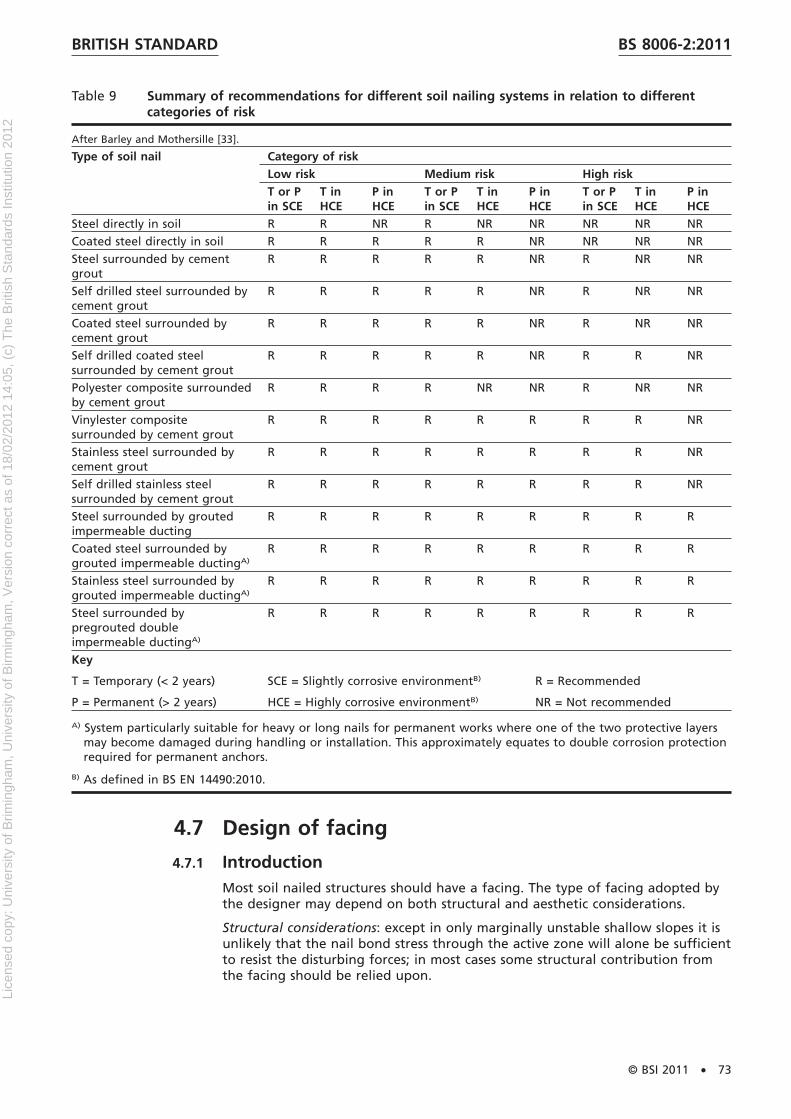
Table 9 Summary of recommendations for different soil nailing systems in relation to differentcategories of risk
After Barley and Mothersille [33].
Type of soil nail Category of riskLow risk Medium risk High riskT or Pin SCE
T inHCE
P inHCE
T or Pin SCE
T inHCE
P inHCE
T or Pin SCE
T inHCE
P inHCE
Steel directly in soil R R NR R NR NR NR NR NRCoated steel directly in soil R R R R R NR NR NR NRSteel surrounded by cementgrout
R R R R R NR R NR NR
Self drilled steel surrounded bycement grout
R R R R R NR R NR NR
Coated steel surrounded bycement grout
R R R R R NR R NR NR
Self drilled coated steelsurrounded by cement grout
R R R R R NR R R NR
Polyester composite surroundedby cement grout
R R R R NR NR R NR NR
Vinylester compositesurrounded by cement grout
R R R R R R R R NR
Stainless steel surrounded bycement grout
R R R R R R R R NR
Self drilled stainless steelsurrounded by cement grout
R R R R R R R R NR
Steel surrounded by groutedimpermeable ducting
R R R R R R R R R
Coated steel surrounded bygrouted impermeable ductingA)
R R R R R R R R R
Stainless steel surrounded bygrouted impermeable ductingA)
R R R R R R R R R
Steel surrounded bypregrouted doubleimpermeable ductingA)
R R R R R R R R R
Key
T = Temporary (< 2 years)
P = Permanent (> 2 years)
SCE = Slightly corrosive environmentB)
HCE = Highly corrosive environmentB)
R = Recommended
NR = Not recommended
A) System particularly suitable for heavy or long nails for permanent works where one of the two protective layersmay become damaged during handling or installation. This approximately equates to double corrosion protectionrequired for permanent anchors.
B) As defined in BS EN 14490:2010.
4.7 Design of facing
4.7.1 IntroductionMost soil nailed structures should have a facing. The type of facing adopted bythe designer may depend on both structural and aesthetic considerations.
Structural considerations: except in only marginally unstable shallow slopes it isunlikely that the nail bond stress through the active zone will alone be sufficientto resist the disturbing forces; in most cases some structural contribution fromthe facing should be relied upon.
BRITISH STANDARD BS 8006-2:2011
© BSI 2011 • 73
Lice
nsed
cop
y: U
nive
rsity
of B
rimin
gham
, Uni
vers
ity o
f Birm
ingh
am, V
ersi
on c
orre
ct a
s of
18/
02/2
012
14:0
5, (
c) T
he B
ritis
h S
tand
ards
Inst
itutio
n 20
12

The facing may be relied upon to provide this structural contribution eitherthrough discrete elements such as nail plates, which might only require theaddition of a soft facing, or by a continuous structural flexible or hard facingspanning between nails, or by a combination of nail plate and flexible facing.
Aesthetic considerations: Many early soil nailed structures were constructed withsprayed concrete faces which may be considered inappropriate for manypotential applications. More recently a variety of methods have been developed,which may be used to provide vegetated faces, particularly to slopes of 60° orless while other proprietary hard facings have also been developed, which maybe used to offer a variety of alternative finishes.
4.7.2 Type of facing
4.7.2.1 Soft
Soft facings should not be used to perform a long term role but may beprovided to stabilize the slope surface while vegetation establishes itself. Theirmain function may be to retain a topsoil layer and prevent erosion. Soft facingsshould not be used for slopes that are steeper than where the soil forming theslope would be naturally stable when protected from weathering. However, theneed to protect topsoil from wash off in the short term may limit most soft faceinstallations to 45° or less. Many types of geogrids, cellular geofabrics and lightmetallic mesh may be used, including degradable coir mats. The solution chosenshould depend on the steepness of the slope and the type of vegetationenvisaged.
4.7.2.2 Flexible
Flexible structural facings may be used to provide long-term stability of the faceby supporting the soil between nail locations and transmitting the load from thesoil to the soil nails via the nail heads. Flexible facing may be used to providesupport through the mobilization of tensile forces within them and thereforesome deformation is required in order for a component of these forces to actnormal to the face. Flexible facings are not normally recommended forpermanent slopes in excess of 70° (60° for complex flexible faces; see 4.7.6.4.3).
Materials used often comprise coated metallic meshes of either the woven orwelded types which are considered “continuous” in the design process; detailedconsideration should be given to the jointing of these materials (either byphysical connections or overlaps) in order to ensure continuity. Edge andtermination details should also be considered carefully.
The concentrations of load around the nail plate should be given particularattention to ensure that adequate resistance to punching and rupture isprovided.
NOTE Geosynthetic materials rarely meet these criteria.
4.7.2.3 Hard
Hard facings may be used to provide the same function as flexible structuralfacing but require far less deformation in order to mobilize their strength andmay be designed for faces up to 90°. Hard facings may be formed from:reinforced concrete (sprayed, cast in situ or pre-cast panels), crib work orgabions. Existing retaining walls which are to be strengthened/stabilized by soilnailing may also be considered to act as a hard facing.
Where hard facings are largely impermeable they may require additionaldrainage arrangements beyond that which might be required for a morepermeable face.
BRITISH STANDARDBS 8006-2:2011
74 • © BSI 2011
Lice
nsed
cop
y: U
nive
rsity
of B
rimin
gham
, Uni
vers
ity o
f Birm
ingh
am, V
ersi
on c
orre
ct a
s of
18/
02/2
012
14:0
5, (
c) T
he B
ritis
h S
tand
ards
Inst
itutio
n 20
12

4.7.3 MaterialsNOTE Third-party certification of materials is accredited by UKAS (www.ukas.com)in the UK and members of the IAF (www.iaf.nu) in the rest of the world. Forexample, BBA and BRE are UKAS accredited.
4.7.3.1 Nail plates
NOTE 1 Nail plates are usually square and fabricated from mild steel plate to a sizeand thickness dictated by structural and durability considerations.
Doming around the central hole of a nail plate may be provided to assistnail/plate articulation.
NOTE 2 Proprietary plastic products are also available which offer advantages interms of durability and chemical resistance.
4.7.3.2 Concrete
Concrete facings should conform to the requirements of BS EN 14490:2010 andbe designed in accordance with BS EN 1992-1-1.
4.7.3.3 Metallic meshes
Welded and woven wire meshes should conform to the requirements ofBS EN 14490:2010.
4.7.3.4 Polymeric materials
Particular consideration should be given to UV resistance and straincharacteristics of synthetic materials used at the face.
4.7.3.5 Other facings
Other facing types are permissible provided they meet the engineering anddurability requirements of the design.
4.7.4 Finishes
4.7.4.1 Concrete
Concrete finishes may be in situ, cast or sprayed, or precast in the form ofmodular blocks or panels.
NOTE A variety of surface finishes are available.
4.7.4.2 Masonry
Masonry may be provided as a finish to hard concrete facings but adequateconsideration should be given to deflections.
4.7.4.3 Stone
Dry stone finishes may be achieved by the use of gabions or mesh panels filledwith stone. Angular crushed stone should be selected that has the necessarydurability and frictional characteristics to limit the imposed force on the facing.
4.7.4.4 Cribwork
Both timber and pre-cast concrete crib walls may be used to provide effectivefacings which may also be vegetated.
BRITISH STANDARD BS 8006-2:2011
© BSI 2011 • 75
Lice
nsed
cop
y: U
nive
rsity
of B
rimin
gham
, Uni
vers
ity o
f Birm
ingh
am, V
ersi
on c
orre
ct a
s of
18/
02/2
012
14:0
5, (
c) T
he B
ritis
h S
tand
ards
Inst
itutio
n 20
12

4.7.4.5 Vegetation
4.7.4.5.1 General
In the great majority of cases vegetation should provide the most acceptablefinish to earthworks slopes and can make a significant contribution to thestability of these slopes. Vegetation should be chosen to reflect the surroundingenvironment and may include grasses and shrubs but not new trees which maylead to damage to the face.
Particular care should be taken when choosing vegetation type, face angle,method of seeding and the soil medium at the face given the often hostileenvironment in which these slopes are constructed.
Vegetation may routinely be established on slopes up to about 45°, butlandscaping specialists should be involved for slopes steeper than 45° and up to60° to maximize the likelihood of satisfactory establishment of vegetation.
4.7.4.5.2 Role of vegetation
The various roles of vegetation may be categorised as mechanical, hydrological,thermal, ecological or environmental with the beneficial effects beingprotection, stabilisation and water removal.
Vegetation may be selected to enhance the performance of a soil nailed slopeby one or more of the following:
a) providing protection against UV radiation to any geosynthetics in the face;
b) controlling erosion by shielding against impact of weather, by acting as areservoir, as a soil binder through root action and a barrier to downwardmovement of debris;
c) through evapotranspiration;
d) increasing shear strength of the retained soil by reduction of pore waterpressures;
e) increasing the shear strength of the retained soil by root reinforcement.
4.7.4.5.3 Plant characteristics
The suitability for particular plant types is dependent on a number ofchracteristics:
a) vigour;
b) resistance to erosion;
c) drought-tolerant;
d) ability to grow in poor infertile soils;
e) ability to grow in shady conditions.
Planting should be chosen for its ability to withstand waterlogging for aquaticapplications.
4.7.4.5.4 Site appraisal
It is vital that the relevant characteristics and conditions of a site are taken intoaccount when designing the vegetation for the face. In difficult or hostileenvironments, such as adjacent to a motorway where de-icing salts might bepresent, the following additional information may be required:
a) site observations: geology, hydrology, microclimate;
b) site investigation and analysis: grading, pH, nutrient levels, contaminants.
BRITISH STANDARDBS 8006-2:2011
76 • © BSI 2011
Lice
nsed
cop
y: U
nive
rsity
of B
rimin
gham
, Uni
vers
ity o
f Birm
ingh
am, V
ersi
on c
orre
ct a
s of
18/
02/2
012
14:0
5, (
c) T
he B
ritis
h S
tand
ards
Inst
itutio
n 20
12

4.7.4.5.5 Plant types
The most common type of vegetation that is adopted is grass. Species that aredrought resistant and low growing are generally used. A mixture of species islikely to increase the probability of success i.e. grasses and legumes as these willprovide rapid growth and erosion protection.
It is recommended that advice is sought from a specialist consultant with respectto the appropriate species.
4.7.4.5.6 Planting and seeding
4.7.4.5.6.1 Grass
Establishment of grass may be achieved in a number of ways.
a) Turf can be supplied with a range of seed mixes and sizes to suit particularsite conditions and construction methods. Reinforced slopes with a faceangle up to 45° do not generally require a structural facing and in suchsituations the turf can be placed directly on a prepared topsoil surfacealthough it will be necessary to pin it in place. As the face angle increasesthe turf is retained behind some form of grid and is required to be smallerin section.
b) Seeded topsoil, either placed within erosion matting materials, containedbehind a mesh or in degradable bags behind a wrap-around face is alsocommon.
c) Pre-seeded mats, blankets or meshes are also used to provide short-termprotection to the face until the vegetation establishes. Some meshes willremain durable and provide longer-term assistance to the vegetation insituations where the erosion forces are significant.
d) Hydroseeding has also been used successfully with careful specification anda sufficient thickness of carrier material.
4.7.4.5.6.2 Discrete planting
The planting of individual plants on soil nailed slopes may be achieved byplanting in prepared holes. The structural facing should not be cut unless thishas been specifically allowed for in the design.
4.7.4.5.7 Design considerations
The following factors should be considered when deciding on the vegetationselection.
a) Direction of slope. The direction in which a slope faces is significant as southand west facing slopes receive more direct sunlight and so ambienttemperatures can be high and vegetation growth difficult.
b) Prevailing wind. The direction of the prevailing wind and its moisturecarrying capacity also need to be considered.
c) Drought. Some species have longer roots which will survive drought betterthan shallow rooted species. In particular circumstances irrigation may formpart of the solution and allow a wider range of vegetation to be usedalthough there are cost implications.
d) Growing season. The growing season for vegetation in the more northernareas of the UK may require installation of the permanent vegetation to becarried out at a different time to the main works. This may influence theconstruction programme and require temporary measures to be considered.
e) Soil type. The type of soil has a large influence on the types of vegetationthat can thrive on the soil nailed slopes. Sandy soils are prone to dessication
BRITISH STANDARD BS 8006-2:2011
© BSI 2011 • 77
Lice
nsed
cop
y: U
nive
rsity
of B
rimin
gham
, Uni
vers
ity o
f Birm
ingh
am, V
ersi
on c
orre
ct a
s of
18/
02/2
012
14:0
5, (
c) T
he B
ritis
h S
tand
ards
Inst
itutio
n 20
12

and may need special measures to ensure that moisture is present whereasclay soils can be resistant to root penetration.
4.7.4.5.8 Maintenance
It is generally found that vegetative ground cover requires little maintenancealthough continuity of cover and any cutting of vegetation need to beconsidered.
For soil nailed slopes the most important recommendation is to ensurecontinuity of the cover as this greatly assists in maintaining integrity of the soil.
It is usual to only cut vegetation at the bottom of slopes where sight lines needto be maintained.
4.7.5 Design of nail plates for soft or flexible facesThe primary function of the nail plates is to ensure that the required nail force,Tf assumed in the internal stability analyses (4.2.1 and Figure 21) may bemobilized at the front face. A method for calculating the required nail plate sizefor a given nail force is set out in Figure 30 (adapted from HA 68/94 [23]).
NOTE Front face plate bearing tests may be undertaken to measure the platecapacity directly.
The equation for areq in Figure 30 ignores any contribution from the front facingacting between the nail positions.
BRITISH STANDARDBS 8006-2:2011
78 • © BSI 2011
Lice
nsed
cop
y: U
nive
rsity
of B
rimin
gham
, Uni
vers
ity o
f Birm
ingh
am, V
ersi
on c
orre
ct a
s of
18/
02/2
012
14:0
5, (
c) T
he B
ritis
h S
tand
ards
Inst
itutio
n 20
12
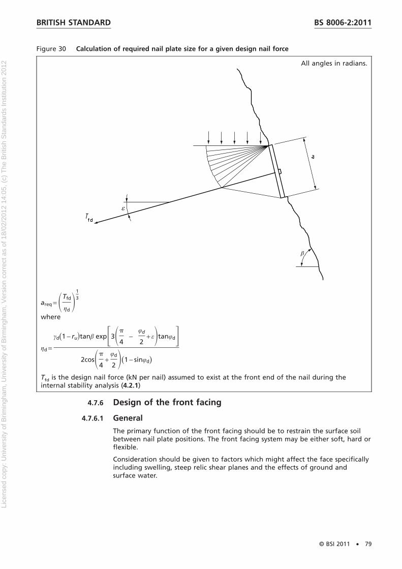
Figure 30 Calculation of required nail plate size for a given design nail force
All angles in radians.
areq = STfd
ηdD
13
where
ηd =
γd(1 − ru�tanβ expF3Sp
4−
φd
2+ εDtanφdG
2cosSp
4+
φd
2 D(1 − sinφd)
Tfd is the design nail force (kN per nail) assumed to exist at the front end of the nail during theinternal stability analysis (4.2.1)
4.7.6 Design of the front facing
4.7.6.1 General
The primary function of the front facing should be to restrain the surface soilbetween nail plate positions. The front facing system may be either soft, hard orflexible.
Consideration should be given to factors which might affect the face specificallyincluding swelling, steep relic shear planes and the effects of ground andsurface water.
BRITISH STANDARD BS 8006-2:2011
© BSI 2011 • 79
Lice
nsed
cop
y: U
nive
rsity
of B
rimin
gham
, Uni
vers
ity o
f Birm
ingh
am, V
ersi
on c
orre
ct a
s of
18/
02/2
012
14:0
5, (
c) T
he B
ritis
h S
tand
ards
Inst
itutio
n 20
12
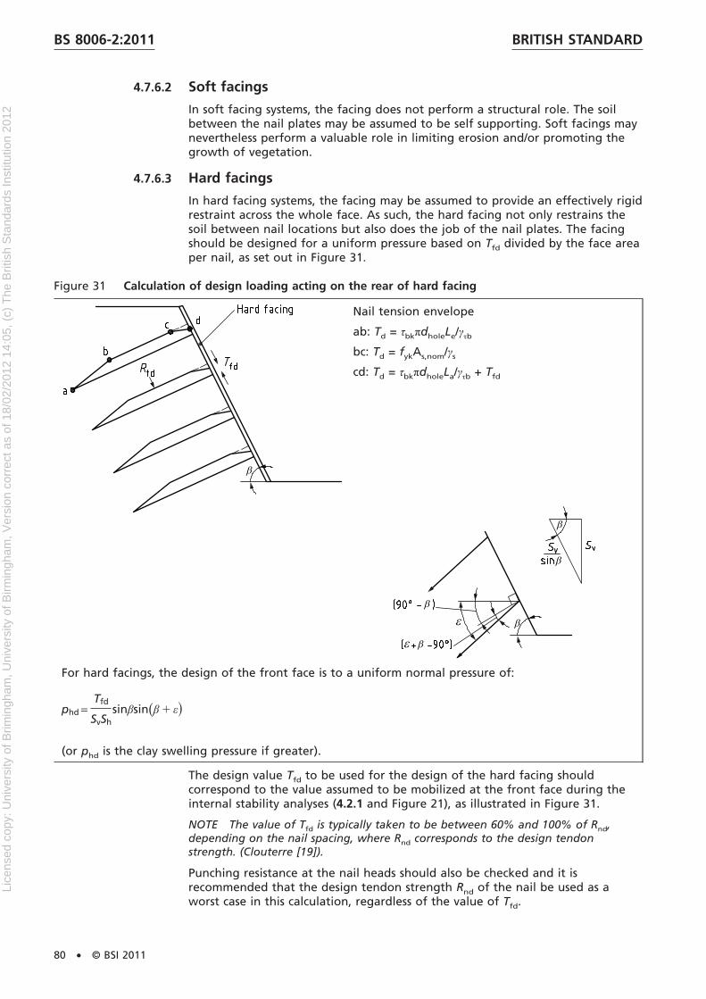
4.7.6.2 Soft facings
In soft facing systems, the facing does not perform a structural role. The soilbetween the nail plates may be assumed to be self supporting. Soft facings maynevertheless perform a valuable role in limiting erosion and/or promoting thegrowth of vegetation.
4.7.6.3 Hard facings
In hard facing systems, the facing may be assumed to provide an effectively rigidrestraint across the whole face. As such, the hard facing not only restrains thesoil between nail locations but also does the job of the nail plates. The facingshould be designed for a uniform pressure based on Tfd divided by the face areaper nail, as set out in Figure 31.
Figure 31 Calculation of design loading acting on the rear of hard facing
Nail tension envelope
ab: Td = τbkπdholeLe/γτb
bc: Td = fykAs,nom/γs
cd: Td = τbkπdholeLa/γτb + Tfd
For hard facings, the design of the front face is to a uniform normal pressure of:
phd =Tfd
SvShsinβsin(β 1 ε�
(or phd is the clay swelling pressure if greater).
The design value Tfd to be used for the design of the hard facing shouldcorrespond to the value assumed to be mobilized at the front face during theinternal stability analyses (4.2.1 and Figure 21), as illustrated in Figure 31.
NOTE The value of Tfd is typically taken to be between 60% and 100% of Rnd,depending on the nail spacing, where Rnd corresponds to the design tendonstrength. (Clouterre [19]).
Punching resistance at the nail heads should also be checked and it isrecommended that the design tendon strength Rnd of the nail be used as aworst case in this calculation, regardless of the value of Tfd.
BRITISH STANDARDBS 8006-2:2011
80 • © BSI 2011
Lice
nsed
cop
y: U
nive
rsity
of B
rimin
gham
, Uni
vers
ity o
f Birm
ingh
am, V
ersi
on c
orre
ct a
s of
18/
02/2
012
14:0
5, (
c) T
he B
ritis
h S
tand
ards
Inst
itutio
n 20
12

Where hard facing systems are used, nominal nail plates may still be required inthe short term in order to provide adequate face stability during construction,before installation of the hard facing.
4.7.6.4 Flexible facings
4.7.6.4.1 General
Flexible facing systems represent an intermediate solution, mid-way betweensoft and hard facings. Flexible facing systems perform a structural role, but somedeformation (often considerable deformation) is likely to be required beforetheir design strength can be mobilised. The design of these systems isconsequently more problematic than for soft or hard facings and certainrestrictions apply on when they can be used.
Flexible facing systems may be either “simple” or “complex”.
4.7.6.4.2 Simple flexible facings
A simple flexible facing restrains the surface soil between the nail platepositions only. The nail plates continue to be designed according to Figure 30for the assumed design strength of the nails at the front face, without anycontribution from the flexible facing. But the surface soil between the nailplates is not self supporting and the facing must be designed to restrain it. Amethod for calculating the loading to be resisted by the facing based on atwo-part wedge failure mechanism forming between two rows of nails is givenin Figure 32.
The flexible facing may be designed to meet this loading by assuming that itacts as a tensioned catenary as shown in Figure 33.
NOTE δv represents the inevitable vertical shortening of the slope which will occurduring its design lifetime (say 0.1% Lo to 0.2% Lo). This acts to compromise (i.e.reduce) the tension in the catenary.
An approximate allowance for the 3D nature of the nail head locations may beincorporated by defining the effective catenary span Lo as Œ(sv
2 + sh2) instead of
simply sv.
The maximum horizontal deflection should be kept within serviceability limits. Amaximum deflection of 0.02 Lo is recommended.
The front facing should also be designed to resist punching shear around theperimeter of the nail plate.
BRITISH STANDARD BS 8006-2:2011
© BSI 2011 • 81
Lice
nsed
cop
y: U
nive
rsity
of B
rimin
gham
, Uni
vers
ity o
f Birm
ingh
am, V
ersi
on c
orre
ct a
s of
18/
02/2
012
14:0
5, (
c) T
he B
ritis
h S
tand
ards
Inst
itutio
n 20
12

Figure 32 Calculation of design loading acting on a simple flexible facing
�F1 + F2)d=
W1(tanε1 − tanφd) +U1tanφd
cosε1
(1 + tanε1tanφd) +
W2(tanε2 − tanφd) +U2tanφd
cosε2
(1 + tanε2tanφd)
at the worst combination of ε1 and ε2.
L 5 ŒSv+Sh ,
⇒pmd=F1+F2 / L .
BRITISH STANDARDBS 8006-2:2011
82 • © BSI 2011
Lice
nsed
cop
y: U
nive
rsity
of B
rimin
gham
, Uni
vers
ity o
f Birm
ingh
am, V
ersi
on c
orre
ct a
s of
18/
02/2
012
14:0
5, (
c) T
he B
ritis
h S
tand
ards
Inst
itutio
n 20
12
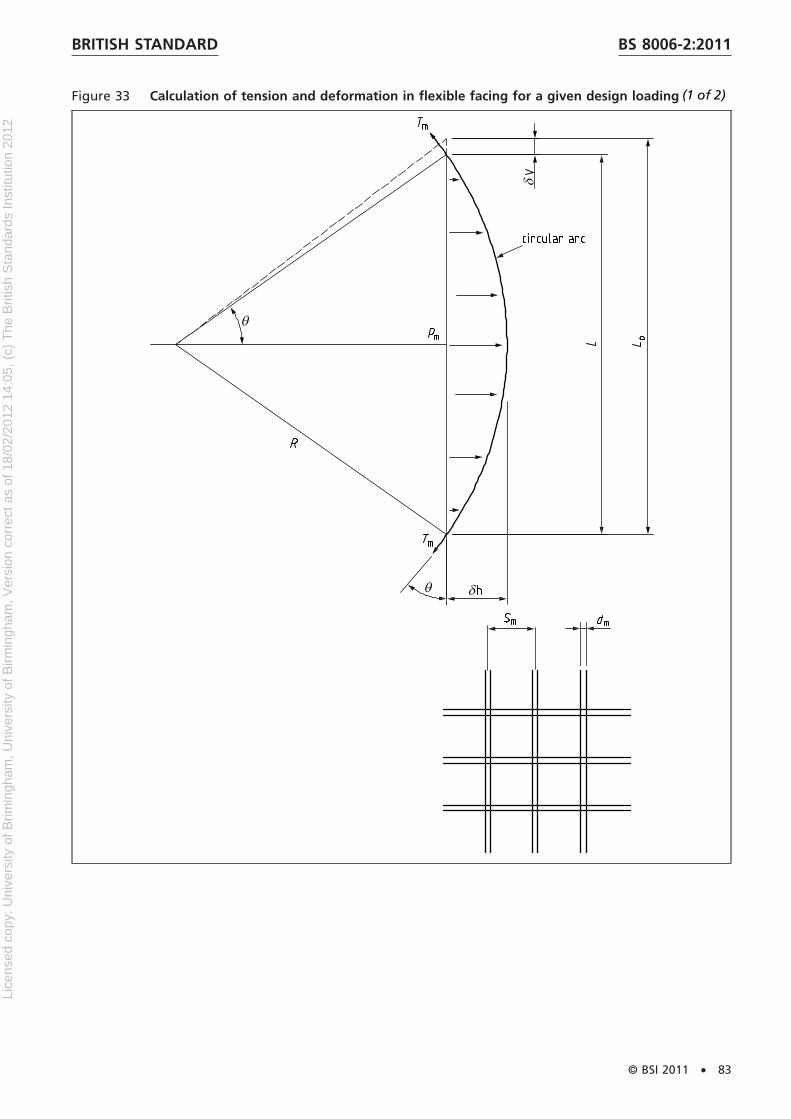
Figure 33 Calculation of tension and deformation in flexible facing for a given design loading
BRITISH STANDARD BS 8006-2:2011
© BSI 2011 • 83
(1 of 2)
Lice
nsed
cop
y: U
nive
rsity
of B
rimin
gham
, Uni
vers
ity o
f Birm
ingh
am, V
ersi
on c
orre
ct a
s of
18/
02/2
012
14:0
5, (
c) T
he B
ritis
h S
tand
ards
Inst
itutio
n 20
12

Figure 33 Calculation of tension and deformation in flexible facing for a given design loading
Based on the properties of a circle.
Method
Select mesh (dm, Sm) such that required pmd (from Figure32 or Figure 34) may be met at acceptable δh.
2Rδh 5L2
4, θ 5 sin−1
L
2R
εm =2Rθ 2 L0
L0, Tmd =
εmEm
pdm
4
γs
pmd =2Tmdsinθ
LSm
where
L0 = ŒSh + Sv;
L 5 L0 − δv;
δh ≤ 0.02L0, say.
4.7.6.4.3 Complex flexible facings
Complex flexible facings are assumed not only to restrain the soil between nailpositions, but also to contribute to the nail plate capacity. This option may beused when the nail plate size calculated according to Figure 30 would otherwisebe excessively large. It is emphasized that this option will involve greaterdeformation of the front face than a simple flexible facing in order to mobilizethe additional necessary catenary tension. If this deformation is unacceptable,then a hard facing should be chosen. Complex flexible facings should not beused for permanent slopes steeper than around 60°, or for permanent slopeswhere the maximum nail spacing (sv or sh) exceeds approximately 1 m withoutrigorous analysis to show that they will perform as intended.
Such a method for designing complex flexible facings is given in Figure 34,which provides a face pressure pm such that the required value of Tf may bemobilized in the nails for internal stability.
BRITISH STANDARDBS 8006-2:2011
84 • © BSI 2011
(2 of 2)
Lice
nsed
cop
y: U
nive
rsity
of B
rimin
gham
, Uni
vers
ity o
f Birm
ingh
am, V
ersi
on c
orre
ct a
s of
18/
02/2
012
14:0
5, (
c) T
he B
ritis
h S
tand
ards
Inst
itutio
n 20
12
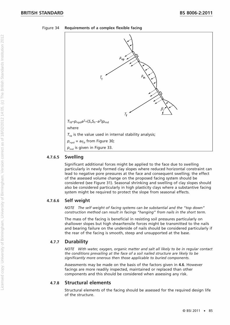
Figure 34 Requirements of a complex flexible facing
Tfd=pnpda2+(SvSh−a2)pmd
where
Tfd is the value used in internal stability analysis;
pnpd = aηd from Figure 30;
pmd is given in Figure 33.
4.7.6.5 Swelling
Significant additional forces might be applied to the face due to swellingparticularly in newly formed clay slopes where reduced horizontal constraint canlead to negative pore pressures at the face and consequent swelling; the effectof the assessed volume change on the proposed facing system should beconsidered (see Figure 31). Seasonal shrinking and swelling of clay slopes shouldalso be considered particularly in high plasticity clays where a substantive facingsystem might be required to protect the slope from seasonal effects.
4.7.6.6 Self weight
NOTE The self weight of facing systems can be substantial and the “top down”construction method can result in facings “hanging” from nails in the short term.
The mass of the facing is beneficial in resisting soil pressures particularly onshallower slopes but high shear/tensile forces might be transmitted to the nailsand bearing failure on the underside of nails should be considered particularly ifthe rear of the facing is smooth, steep and unsupported at the base.
4.7.7 DurabilityNOTE With water, oxygen, organic matter and salt all likely to be in regular contactthe conditions prevailing at the face of a soil nailed structure are likely to besignificantly more onerous then those applicable to buried components.
Assessments may be made on the basis of the factors given in 4.6. Howeverfacings are more readily inspected, maintained or replaced than othercomponents and this should be considered when assessing any risk.
4.7.8 Structural elementsStructural elements of the facing should be assessed for the required design lifeof the structure.
BRITISH STANDARD BS 8006-2:2011
© BSI 2011 • 85
Lice
nsed
cop
y: U
nive
rsity
of B
rimin
gham
, Uni
vers
ity o
f Birm
ingh
am, V
ersi
on c
orre
ct a
s of
18/
02/2
012
14:0
5, (
c) T
he B
ritis
h S
tand
ards
Inst
itutio
n 20
12
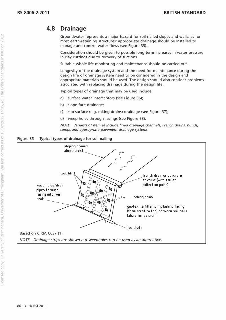
4.8 DrainageGroundwater represents a major hazard for soil-nailed slopes and walls, as formost earth-retaining structures; appropriate drainage should be installed tomanage and control water flows (see Figure 35).
Consideration should be given to possible long-term increases in water pressurein clay cuttings due to recovery of suctions.
Suitable whole-life monitoring and maintenance should be carried out.
Longevity of the drainage system and the need for maintenance during thedesign life of drainage system need to be considered in the design andappropriate materials should be used. The design should also consider problemsassociated with replacing drainage during the design life.
Typical types of drainage that may be used include:
a) surface water interceptors (see Figure 36);
b) slope face drainage;
c) sub-surface (e.g. raking drains) drainage (see Figure 37);
d) weep holes through facings (see Figure 38).
NOTE Variants of item a) include lined drainage channels, French drains, bunds,sumps and appropriate pavement drainage systems.
Figure 35 Typical types of drainage for soil nailing
Based on CIRIA C637 [1].
NOTE Drainage strips are shown but weepholes can be used as an alternative.
BRITISH STANDARDBS 8006-2:2011
86 • © BSI 2011
Lice
nsed
cop
y: U
nive
rsity
of B
rimin
gham
, Uni
vers
ity o
f Birm
ingh
am, V
ersi
on c
orre
ct a
s of
18/
02/2
012
14:0
5, (
c) T
he B
ritis
h S
tand
ards
Inst
itutio
n 20
12

Figure 36 Typical surface water interceptor detail above a steep soil-nailed slope
Based on CIRIA C637 [1].
NOTE 1 The concrete channel size has to match the design water flow.
NOTE 2 A crest drain ought to always be considered for permanent soil nail applications with aslope behind.
NOTE 3 For safety reasons, it is recommended that drainage and crest details are installed prior toexcavation wherever possible.
Figure 37 Example of a raking drain in a steep soil-nailed slope
Based on CIRIA C637 [1].
NOTE One or more levels of raking drains may be used.
BRITISH STANDARD BS 8006-2:2011
© BSI 2011 • 87
Lice
nsed
cop
y: U
nive
rsity
of B
rimin
gham
, Uni
vers
ity o
f Birm
ingh
am, V
ersi
on c
orre
ct a
s of
18/
02/2
012
14:0
5, (
c) T
he B
ritis
h S
tand
ards
Inst
itutio
n 20
12
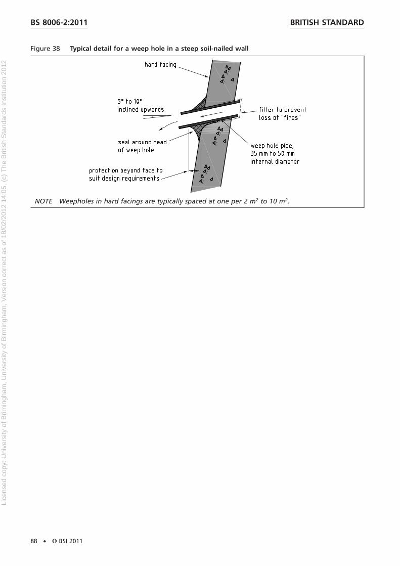
Figure 38 Typical detail for a weep hole in a steep soil-nailed wall
NOTE Weepholes in hard facings are typically spaced at one per 2 m2 to 10 m2.
BRITISH STANDARDBS 8006-2:2011
88 • © BSI 2011
Lice
nsed
cop
y: U
nive
rsity
of B
rimin
gham
, Uni
vers
ity o
f Birm
ingh
am, V
ersi
on c
orre
ct a
s of
18/
02/2
012
14:0
5, (
c) T
he B
ritis
h S
tand
ards
Inst
itutio
n 20
12
Section 5 : Serviceability and movements
5.1 Serviceability limit stateFor each geotechnical design situation it should be verified that no serviceabilitylimit state, as defined in BS EN 1990, is exceeded.
NOTE 1 The serviceability limit states are defined as: “states that correspond toconditions beyond which specified service requirements or a structure or structuralmember are no longer met” (BS EN 1991:2002, 1.5.2.14).
Serviceability limit states should be established prior to the design for the soilnailing being undertaken.
NOTE 2 Due to the complex interaction between the soil nails, the surroundingground and the facing, which is three dimensional in nature, precise calculation ofdeflection is not straightforward and is rarely warranted except for particularlysensitive situations.
For steep faces estimation of likely deformation may most easily be achievedwith reference to empirical relationships derived from field observations.
For less steep face angles tending to normal slope gradients prevention of theoccurrence of SLS conditions may be achieved by limiting mobilized shearstrengths.
For each design situation it should be verified that the serviceability limit statewill not be exceeded for:
a) the soil nail structure or soil nail slope under consideration including allconstituent elements, which can include:
1) clearances of tolerances relating to the final position of the soil nailfacing;
2) crack control in the nail grout and/or concrete facing;
b) adjacent structures, services, etc., that might be influenced by movementsgenerated by excavation or soil nailing construction.
The importance of maintaining the aesthetic appearance of the structure overthe design life should also be considered.
Ground movements and element deflection should be considered, taking intoaccount the range of variation in ground conditions that could be reasonablyanticipated over the area of soil nailing under consideration:
a) during construction (particularly where top down construction is proposed);
b) for the design life following completion of construction; and
c) for transient or accidental conditions.
The influence of movement or deflection on the durability of elements shouldreceive particular attention (e.g. cracking of grout and creep of polymericmaterials).
Estimation of movement may be based on:
a) empirical relationships;
b) numerical modelling;
c) case studies.
BRITISH STANDARD BS 8006-2:2011
© BSI 2011 • 89
Lice
nsed
cop
y: U
nive
rsity
of B
rimin
gham
, Uni
vers
ity o
f Birm
ingh
am, V
ersi
on c
orre
ct a
s of
18/
02/2
012
14:0
5, (
c) T
he B
ritis
h S
tand
ards
Inst
itutio
n 20
12

5.2 Serviceability limit state analysisFor routine situations where limit equilibrium design methods are adopteddirect prediction of deformations are not usually possible; in such situationsdeformations may be predicted approximately using empirical correlations.
Where critical situations require greater confidence in predicted deformations, ahigh level of analysis such as numerical analysis may be adopted. Where SLSanalyses are undertaken characteristic values of parameters should be used (i.e.partial factors = 1.0).
5.3 Estimation of movement – GeneralConsideration should be given that actions causing movement can be due to thefollowing combinations of factors:
a) self weight effects (particularly where top down construction is proposed);
b) application of external forces or loads (for example water pressures, otherattached structures, surcharges, accidental impacts);
c) time dependent phenomena (for example swelling/heave in cohesive soils);
d) seismic forces;
e) sloughing of soil between nail heads.
To mobilize forces in passive soil nails and facings movement is required;pre-stressed soil nails may be effective where limiting movements is a primeobjective.
Soil nailing is a three dimensional problem and this should be considered whenestimating movements.
Estimation of movement may need to consider:
1) magnitude of movement;
2) rate of movement.
Consideration should also be given that movements depend on the followingfactors:
i) construction rate;
ii) nail spacing, length and inclination;
iii) excavation height;
iv) nail and soil stiffness;
v) facing type and stiffness;
vi) compressibility of foundation soils;
vii) magnitude and location of externally applied loads or forces.
5.4 Use of empirical relationshipsCOMMENTARY ON 5.4
Where the soil nailing has a steep or vertical face constructed in a top downsequence the soil nailed zone tends to rotate outwards and downwards at the topas construction and excavation proceeds. With each excavation stage the soil nailsprogressively strain and elongate as they mobilize load. In this situation themovements occurring during construction are usually the most significant.
BRITISH STANDARDBS 8006-2:2011
90 • © BSI 2011
Lice
nsed
cop
y: U
nive
rsity
of B
rimin
gham
, Uni
vers
ity o
f Birm
ingh
am, V
ersi
on c
orre
ct a
s of
18/
02/2
012
14:0
5, (
c) T
he B
ritis
h S
tand
ards
Inst
itutio
n 20
12
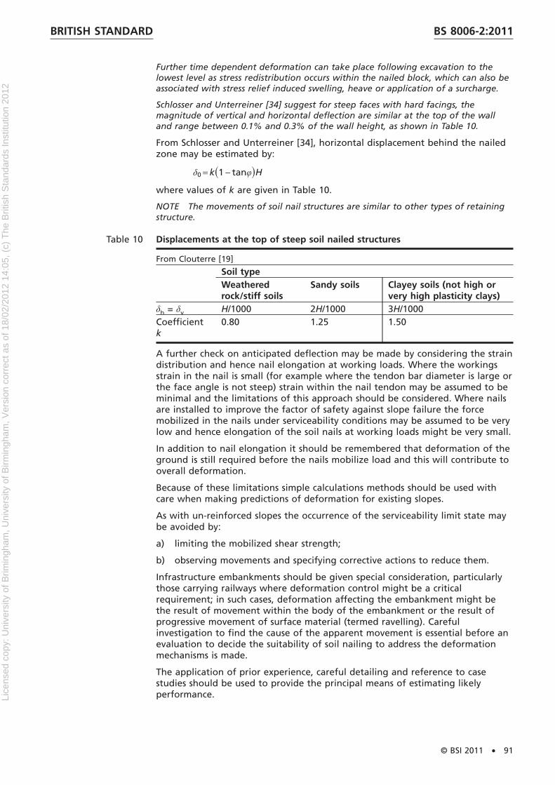
Further time dependent deformation can take place following excavation to thelowest level as stress redistribution occurs within the nailed block, which can also beassociated with stress relief induced swelling, heave or application of a surcharge.
Schlosser and Unterreiner [34] suggest for steep faces with hard facings, themagnitude of vertical and horizontal deflection are similar at the top of the walland range between 0.1% and 0.3% of the wall height, as shown in Table 10.
From Schlosser and Unterreiner [34], horizontal displacement behind the nailedzone may be estimated by:
δ0 = k�1 − tanφ�H
where values of k are given in Table 10.
NOTE The movements of soil nail structures are similar to other types of retainingstructure.
Table 10 Displacements at the top of steep soil nailed structures
From Clouterre [19]
Soil typeWeatheredrock/stiff soils
Sandy soils Clayey soils (not high orvery high plasticity clays)
δh = δv H/1000 2H/1000 3H/1000Coefficientk
0.80 1.25 1.50
A further check on anticipated deflection may be made by considering the straindistribution and hence nail elongation at working loads. Where the workingsstrain in the nail is small (for example where the tendon bar diameter is large orthe face angle is not steep) strain within the nail tendon may be assumed to beminimal and the limitations of this approach should be considered. Where nailsare installed to improve the factor of safety against slope failure the forcemobilized in the nails under serviceability conditions may be assumed to be verylow and hence elongation of the soil nails at working loads might be very small.
In addition to nail elongation it should be remembered that deformation of theground is still required before the nails mobilize load and this will contribute tooverall deformation.
Because of these limitations simple calculations methods should be used withcare when making predictions of deformation for existing slopes.
As with un-reinforced slopes the occurrence of the serviceability limit state maybe avoided by:
a) limiting the mobilized shear strength;
b) observing movements and specifying corrective actions to reduce them.
Infrastructure embankments should be given special consideration, particularlythose carrying railways where deformation control might be a criticalrequirement; in such cases, deformation affecting the embankment might bethe result of movement within the body of the embankment or the result ofprogressive movement of surface material (termed ravelling). Carefulinvestigation to find the cause of the apparent movement is essential before anevaluation to decide the suitability of soil nailing to address the deformationmechanisms is made.
The application of prior experience, careful detailing and reference to casestudies should be used to provide the principal means of estimating likelyperformance.
BRITISH STANDARD BS 8006-2:2011
© BSI 2011 • 91
Lice
nsed
cop
y: U
nive
rsity
of B
rimin
gham
, Uni
vers
ity o
f Birm
ingh
am, V
ersi
on c
orre
ct a
s of
18/
02/2
012
14:0
5, (
c) T
he B
ritis
h S
tand
ards
Inst
itutio
n 20
12

5.5 Numerical modellingFor particularly complex problems or where the estimation of serviceabilitydeformations is critical numerical modelling may be undertaken, for exampleusing finite element or finite difference methods. See also 4.4.
NOTE 1 The accuracy of numerical modelling depends on many factors includingthe constitutive framework for modelling the soil, the nails and the facing and theinteraction between the various elements.
Where there is uncertainty over the best way to formulate numerical modelscareful calibration with other experience, supplemented with constructionmonitoring should be undertaken if deformations predicted by numericalanalysis are to be relied on.
NOTE 2 It is beyond the scope of this standard to provide detailed advice on theessential requirements to be considered when undertaking numerical modelling.
5.6 Case studiesCase studies of measured behaviour may provide a useful guide to anticipatedperformance of new construction.
Historic information should be validated to ensure similarity of:
a) geometry;
b) nail type and installation method;
c) soil type;
d) external loading regime;
e) construction sequence;
f) facing type.
BRITISH STANDARDBS 8006-2:2011
92 • © BSI 2011
Lice
nsed
cop
y: U
nive
rsity
of B
rimin
gham
, Uni
vers
ity o
f Birm
ingh
am, V
ersi
on c
orre
ct a
s of
18/
02/2
012
14:0
5, (
c) T
he B
ritis
h S
tand
ards
Inst
itutio
n 20
12

Section 6 : Design verification
6.1 Testing
6.1.1 Pullout testingSelection of characteristic parameters for design should be recognized as criticalto ensure adequate and safe structures and slopes. Critical parameters subject tohigh variability should be derived from site specific tests; in particular thepullout resistance between the soil nail and the ground is a fundamentalparameter that strongly influences the design of soil nail applications. In mostcases it is not possible to fully replicate the stress distribution that will occur in aproduction nail by undertaking pull-out tests, therefore when designing nailtests and analysing the results, aspects that might lead to differences inperformance or behaviour of the production nails compared to the test nailsshould be considered, for example:
a) differences in the ambient soil stresses due to differences in location,orientation, depth of embedment and other boundary effects and the waythese differences might affect the mobilized bond stress in the productionnails;
b) variation in magnitude and direction of bond stresses mobilized in pull-outtests and in production nails;
c) variation in the soil strata between the test nail and production naillocations.
In most routine situations pull-out tests remain the only viable means toevaluating nail performance in spite of the limitations of the method. Due tothe mobilization of the strain field in a test nail subject to a pull-out test beingsignificantly different from production nails, pull-out tests on production nailsshould be avoided being confined to sacrificial nails only (see 4.3).
Tests should be spaced to give representative spread across the soil nailedstructure.
6.1.2 Types of soil nail testNOTE BS EN 14490:2010 covers the pullout testing of soil nails.
Two types of soil nail test that may be used are defined in BS EN 14490:2010:
a) Sacrificial test
Sacrificial tests may be used to verify the ultimate bond resistance used in thedesign.
If these tests fail to provide verification of the relevant parameters adopted inthe design a review of the soil nail installation and/or the soil nail length andlayout should be carried out.
These tests may be done significantly in advance of the main construction worksand are usually undertaken before the detailed design is completed. It isessential that such design investigation test nails are installed by the sameconstruction methods and in similar ground conditions as the proposedproduction nails.
b) Production test
Production tests may be used to demonstrate satisfactory soil nail performanceat the accepted load.
Soil nail tests should be selected using Table 11, which shows the purpose ofeach of the types of soil nail test.
BRITISH STANDARD BS 8006-2:2011
© BSI 2011 • 93
Lice
nsed
cop
y: U
nive
rsity
of B
rimin
gham
, Uni
vers
ity o
f Birm
ingh
am, V
ersi
on c
orre
ct a
s of
18/
02/2
012
14:0
5, (
c) T
he B
ritis
h S
tand
ards
Inst
itutio
n 20
12
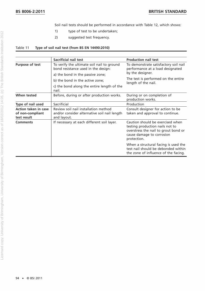
Soil nail tests should be performed in accordance with Table 12, which shows:
1) type of test to be undertaken;
2) suggested test frequency.
Table 11 Type of soil nail test (from BS EN 14490:2010)
Sacrificial nail test Production nail testPurpose of test To verify the ultimate soil nail to ground
bond resistance used in the design:
a) the bond in the passive zone;
b) the bond in the active zone;
c) the bond along the entire length of thenail.
To demonstrate satisfactory soil nailperformance at a load designatedby the designer.
The test is performed on the entirelength of the nail.
When tested Before, during or after production works. During or on completion ofproduction works.
Type of nail used Sacrificial ProductionAction taken in caseof non-complianttest result
Review soil nail installation methodand/or consider alternative soil nail lengthand layout.
Consult designer for action to betaken and approval to continue.
Comments If necessary at each different soil layer. Caution should be exercised whentesting production nails not tooverstress the nail to grout bond orcause damage to corrosionprotection.
When a structural facing is used thetest nail should be debonded withinthe zone of influence of the facing.
BRITISH STANDARDBS 8006-2:2011
94 • © BSI 2011
Lice
nsed
cop
y: U
nive
rsity
of B
rimin
gham
, Uni
vers
ity o
f Birm
ingh
am, V
ersi
on c
orre
ct a
s of
18/
02/2
012
14:0
5, (
c) T
he B
ritis
h S
tand
ards
Inst
itutio
n 20
12

Table 12 Recommended test frequency (from BS EN 14490:2010)
Test type Suggested minimum frequency of load testsSacrificial nail test Production nail test
Geotechnical Category 1:negligible risk to propertyor life.
Optional Optional
Geotechnical Category 2:no abnormal risk toproperty or life.
If no comparable experience of soiltype: a minimum of three sacrificialnails with at least one sacrificial nailper soil type.
Where direct experience exists thensacrificial nail tests are optional.
2%, minimum of three tests.
These criteria are subject to aminimum of one test per soiltype and per excavation stage.
Geotechnical Category 3:all other structures not inCategory 1 or 2.
A minimum of five sacrificial nails withat least two sacrificial nails per soiltype.
For number of nails:
3%, min. five tests.
These criteria are subject to aminimum of one test per soiltype and per excavation stage.
NOTE 1 Geotechnical Category of structure as defined in BS EN 1997.
NOTE 2 Test nails should be evenly distributed throughout the structure.
NOTE 3 The frequency of testing is a suggested minimum.
NOTE 4 Where sacrificial nail tests are carried out the number of production nail tests can be reduced on apro-rata basis.
NOTE 5 For spacing, less then 0.8 m, a group test of four nails is recommended.
Any element or interface may be subject to testing, for example:
a) soil-nail bond stress;
b) head plate bearing capacity;
c) facing rupture strength;
d) reinforcement/grout bond;
e) grout/concrete strength.
6.2 Nail pullout resistance
6.2.1 Static nail test procedureThe soil nail bond stress is fundamental and should be verified to validate thedesign.
Generally static tests should be performed whereby the test nail is loaded andunloaded incrementally in cycles with the load held constant for each loadincrement. For each load increment displacement should be measured at varioustime increments, e.g. t = 0 min, 1 min, 2 min, 5 min, 10 min, 15 min, 20 min,60 min, until the displacement is less than 0.5 mm between two consecutivereadings. In addition the following minimum load hold periods should beadopted:
a) for the maximum test load Ptest, 10 min;
b) for intermediate test loads, 1 min.
BRITISH STANDARD BS 8006-2:2011
© BSI 2011 • 95
Lice
nsed
cop
y: U
nive
rsity
of B
rimin
gham
, Uni
vers
ity o
f Birm
ingh
am, V
ersi
on c
orre
ct a
s of
18/
02/2
012
14:0
5, (
c) T
he B
ritis
h S
tand
ards
Inst
itutio
n 20
12

If the displacement rate of 0.5 mm between two consecutive readings cannot beachieved for a given test load no further load should be applied and theresidual test load recorded. The ultimate load Pult, should be the minimum ofthe residual load or the minimum test load at which the rate of displacementwas less than 2 mm per log cycle of time:
s2 − s1
logSt2
t1D < 2 mm
where s1 and s2 are the measured nail displacements at time t1 and time t2
respectively.
Table 13 gives recommendations for the static load testing of soil nails. The soilnail designer should, in addition, specify:
a) the number of load cycles;
b) the total test load;
c) the magnitude of the load increments.
NOTE These relatively fast rates of testing might not be appropriate for long-termperformance of nails in stiff clay.
BRITISH STANDARDBS 8006-2:2011
96 • © BSI 2011
Lice
nsed
cop
y: U
nive
rsity
of B
rimin
gham
, Uni
vers
ity o
f Birm
ingh
am, V
ersi
on c
orre
ct a
s of
18/
02/2
012
14:0
5, (
c) T
he B
ritis
h S
tand
ards
Inst
itutio
n 20
12
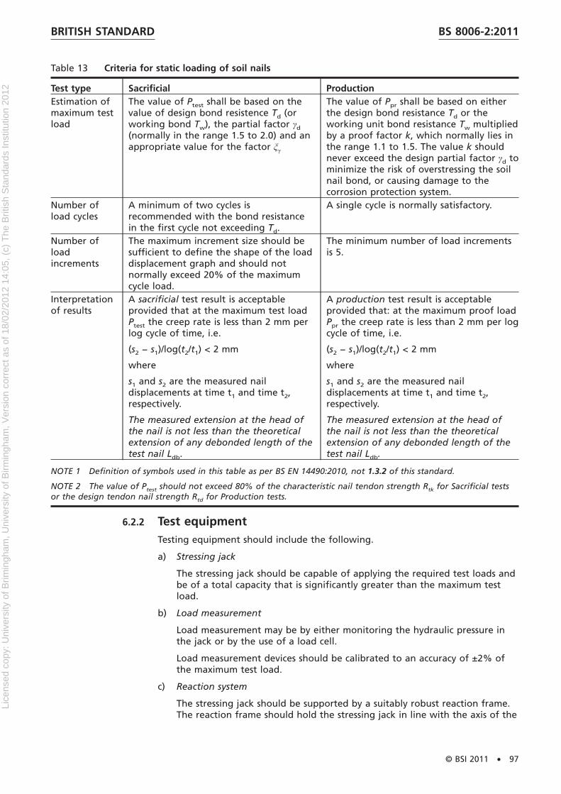
Table 13 Criteria for static loading of soil nails
Test type Sacrificial ProductionEstimation ofmaximum testload
The value of Ptest shall be based on thevalue of design bond resistence Td (orworking bond Tw), the partial factor γd
(normally in the range 1.5 to 2.0) and anappropriate value for the factor ξγ
The value of Ppr shall be based on eitherthe design bond resistance Td or theworking unit bond resistance Tw multipliedby a proof factor k, which normally lies inthe range 1.1 to 1.5. The value k shouldnever exceed the design partial factor γd tominimize the risk of overstressing the soilnail bond, or causing damage to thecorrosion protection system.
Number ofload cycles
A minimum of two cycles isrecommended with the bond resistancein the first cycle not exceeding Td.
A single cycle is normally satisfactory.
Number ofloadincrements
The maximum increment size should besufficient to define the shape of the loaddisplacement graph and should notnormally exceed 20% of the maximumcycle load.
The minimum number of load incrementsis 5.
Interpretationof results
A sacrificial test result is acceptableprovided that at the maximum test loadPtest the creep rate is less than 2 mm perlog cycle of time, i.e.
(s2 − s1)/log(t2/t1) < 2 mm
where
s1 and s2 are the measured naildisplacements at time t1 and time t2,respectively.
The measured extension at the head ofthe nail is not less than the theoreticalextension of any debonded length of thetest nail Ldb.
A production test result is acceptableprovided that: at the maximum proof loadPpr the creep rate is less than 2 mm per logcycle of time, i.e.
(s2 − s1)/log(t2/t1) < 2 mm
where
s1 and s2 are the measured naildisplacements at time t1 and time t2,respectively.
The measured extension at the head ofthe nail is not less than the theoreticalextension of any debonded length of thetest nail Ldb.
NOTE 1 Definition of symbols used in this table as per BS EN 14490:2010, not 1.3.2 of this standard.
NOTE 2 The value of Ptest should not exceed 80% of the characteristic nail tendon strength Rtk for Sacrificial testsor the design tendon nail strength Rtd for Production tests.
6.2.2 Test equipmentTesting equipment should include the following.
a) Stressing jack
The stressing jack should be capable of applying the required test loads andbe of a total capacity that is significantly greater than the maximum testload.
b) Load measurement
Load measurement may be by either monitoring the hydraulic pressure inthe jack or by the use of a load cell.
Load measurement devices should be calibrated to an accuracy of ±2% ofthe maximum test load.
c) Reaction system
The stressing jack should be supported by a suitably robust reaction frame.The reaction frame should hold the stressing jack in line with the axis of the
BRITISH STANDARD BS 8006-2:2011
© BSI 2011 • 97
Lice
nsed
cop
y: U
nive
rsity
of B
rimin
gham
, Uni
vers
ity o
f Birm
ingh
am, V
ersi
on c
orre
ct a
s of
18/
02/2
012
14:0
5, (
c) T
he B
ritis
h S
tand
ards
Inst
itutio
n 20
12
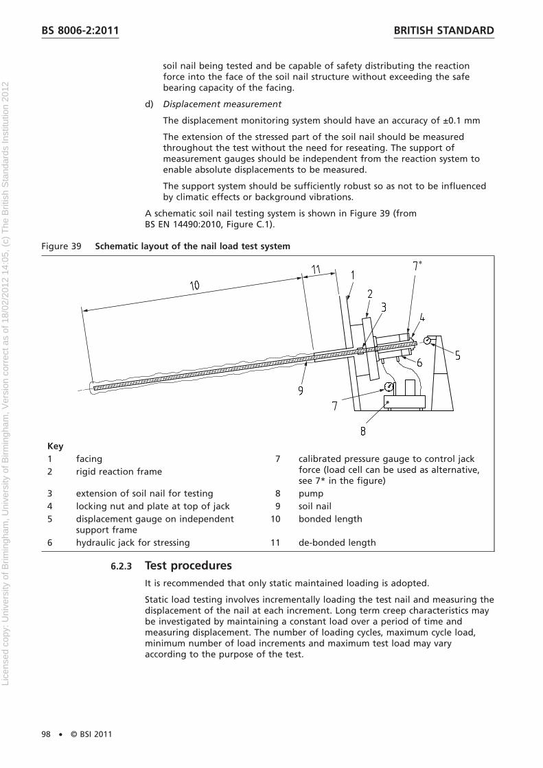
soil nail being tested and be capable of safety distributing the reactionforce into the face of the soil nail structure without exceeding the safebearing capacity of the facing.
d) Displacement measurement
The displacement monitoring system should have an accuracy of ±0.1 mm
The extension of the stressed part of the soil nail should be measuredthroughout the test without the need for reseating. The support ofmeasurement gauges should be independent from the reaction system toenable absolute displacements to be measured.
The support system should be sufficiently robust so as not to be influencedby climatic effects or background vibrations.
A schematic soil nail testing system is shown in Figure 39 (fromBS EN 14490:2010, Figure C.1).
Figure 39 Schematic layout of the nail load test system
Key1 facing 7 calibrated pressure gauge to control jack
force (load cell can be used as alternative,see 7* in the figure)
2 rigid reaction frame
3 extension of soil nail for testing 8 pump4 locking nut and plate at top of jack 9 soil nail5 displacement gauge on independent
support frame10 bonded length
6 hydraulic jack for stressing 11 de-bonded length
6.2.3 Test proceduresIt is recommended that only static maintained loading is adopted.
Static load testing involves incrementally loading the test nail and measuring thedisplacement of the nail at each increment. Long term creep characteristics maybe investigated by maintaining a constant load over a period of time andmeasuring displacement. The number of loading cycles, maximum cycle load,minimum number of load increments and maximum test load may varyaccording to the purpose of the test.
BRITISH STANDARDBS 8006-2:2011
98 • © BSI 2011
Lice
nsed
cop
y: U
nive
rsity
of B
rimin
gham
, Uni
vers
ity o
f Birm
ingh
am, V
ersi
on c
orre
ct a
s of
18/
02/2
012
14:0
5, (
c) T
he B
ritis
h S
tand
ards
Inst
itutio
n 20
12
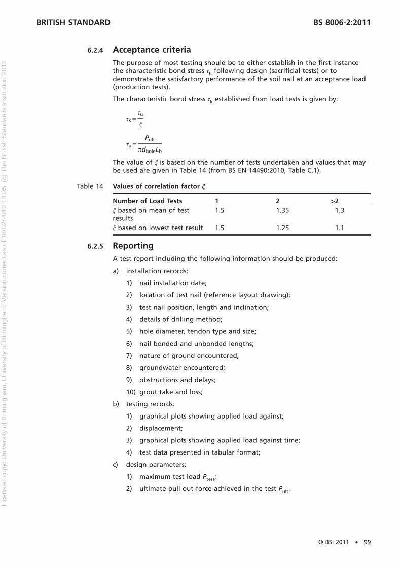
6.2.4 Acceptance criteriaThe purpose of most testing should be to either establish in the first instancethe characteristic bond stress τk following design (sacrificial tests) or todemonstrate the satisfactory performance of the soil nail at an acceptance load(production tests).
The characteristic bond stress τk established from load tests is given by:
τk =τu
ξ
τu =Pult
πdholeLb
The value of ξ is based on the number of tests undertaken and values that maybe used are given in Table 14 (from BS EN 14490:2010, Table C.1).
Table 14 Values of correlation factor ξ
Number of Load Tests 1 2 >2ξ based on mean of testresults
1.5 1.35 1.3
ξ based on lowest test result 1.5 1.25 1.1
6.2.5 ReportingA test report including the following information should be produced:
a) installation records:
1) nail installation date;
2) location of test nail (reference layout drawing);
3) test nail position, length and inclination;
4) details of drilling method;
5) hole diameter, tendon type and size;
6) nail bonded and unbonded lengths;
7) nature of ground encountered;
8) groundwater encountered;
9) obstructions and delays;
10) grout take and loss;
b) testing records:
1) graphical plots showing applied load against;
2) displacement;
3) graphical plots showing applied load against time;
4) test data presented in tabular format;
c) design parameters:
1) maximum test load Ptest;
2) ultimate pull out force achieved in the test Pult.
BRITISH STANDARD BS 8006-2:2011
© BSI 2011 • 99
Lice
nsed
cop
y: U
nive
rsity
of B
rimin
gham
, Uni
vers
ity o
f Birm
ingh
am, V
ersi
on c
orre
ct a
s of
18/
02/2
012
14:0
5, (
c) T
he B
ritis
h S
tand
ards
Inst
itutio
n 20
12

6.3 Materials testingMaterials testing should conform to the following standards, which areconsidered applicable to soil nailing:
a) grout – BS EN 196 (all parts);
b) sprayed concrete – BS EN 14487 (both parts);
c) concrete – BS EN 206-1;
d) reinforcing steel – BS EN 10080.
6.4 Other testsOther tests such as face stability, head plate bearing capacity andnon-destructive testing are out lined in BS EN 14490:2010 and should bespecified as required by the designer.
6.5 MonitoringMonitoring may be undertaken for a variety of reasons including:
a) confirmation that movements or forces do not exceed specified limits;
b) in conjunction with construction undertaking in accordance with theobservational method (see Nicholson et al [35]);
c) to gather data for case history or research purposes.
Whilst often desirable, monitoring is by no means essential for the execution ofsuccessful soil nailing works.
Monitoring of soil nail structures may be undertaken:
1) during construction, especially where top down construction is envisaged;
2) post construction.
The type, extent and accuracy of monitoring should be clearly defined at thefinal design stage, in accordance with BS EN 1997-1:2004, 4.5.
Monitoring should be designed to verify movements or forces adopted in thedesign, or to confirm pre-determined threshold parameters are not exceeded.
6.6 Monitoring during constructionMonitoring of the horizontal and vertical movement of the crest and facing maybe performed at all stages of construction to confirm stability.
If movements approach or exceed threshold values then stabilization measuresor a revised construction sequence should be implemented. The designer shouldreview the design and the construction sequence in light of monitoredbehaviour of the structure making any necessary changes to the design.
6.7 Long-term or post-construction monitoringLong-term and post-construction monitoring should be carried out followingBS EN 14490:2010, 9.5.
BRITISH STANDARDBS 8006-2:2011
100 • © BSI 2011
Lice
nsed
cop
y: U
nive
rsity
of B
rimin
gham
, Uni
vers
ity o
f Birm
ingh
am, V
ersi
on c
orre
ct a
s of
18/
02/2
012
14:0
5, (
c) T
he B
ritis
h S
tand
ards
Inst
itutio
n 20
12

Section 7 : MaintenanceSoil-nailed structures should be designed to withstand the combined effect of allthe deteriorating forces to which they might be reasonably expected to beexposed for a finite period – called the design life.
Regular inspection and maintenance are needed and should be implemented forsuch a design life to be achieved and to make sure that safety is not degraded.
The inspection and maintenance regime should be drawn up, depending on therisk category of the structure.
NOTE The CDM regulations require that a Health and Safety File is set up when anew structure is built. This has to cover maintenance requirements.
Facilities for maintenance (especially for safe and efficient access formaintenance) should be incorporated as part of the design.
Regular inspections/condition appraisal should check the following:
a) movement of facing and localized bulging;
b) movements in the soil-nailed ground and appearance of tension cracks atthe crest;
c) condition of drainage (including moist areas on the facing and flow rates inthe drains) and weep holes not being blocked or clogged;
d) condition of the nails and the facing and the amount of corrosion damage;the time intervals between such checks and their degree of rigour willdepend on the aggressivity of the ground;
e) vegetation growth on the slope or wall; if trees have got too large theymight blow over and cause damage – so they will need to be cut back orcoppiced;
f) degradation of the structure caused by animal or human activity.
Records should be kept of the inspections and of any maintenance carried out.
The environmental value of slopes as habitats for animals and plants isincreasingly being recognized; the times of year and procedures for vegetationmaintenance should take this into account – to minimize disturbance to wildlife.
BRITISH STANDARD BS 8006-2:2011
© BSI 2011 • 101
Lice
nsed
cop
y: U
nive
rsity
of B
rimin
gham
, Uni
vers
ity o
f Birm
ingh
am, V
ersi
on c
orre
ct a
s of
18/
02/2
012
14:0
5, (
c) T
he B
ritis
h S
tand
ards
Inst
itutio
n 20
12

BibliographyStandards publications
For dated references, only the edition cited applies. For undated references, thelatest edition of the referenced document (including any amendments) applies.
BS 1377-3, Methods of test for soils for civil engineering purposes – Chemicaland electro-chemical tests
BS 8002, Code of practice for earth retaining structures
BS EN ISO 1461:1999, Hot dip galvanized coatings on fabricated iron and steelarticles – Specifications and test methods
Other publications
[1] Phear, A., Dew, C., Ozsoy,B., Wharmby, N.J., Judge, J. and Barley, A.D. SoilNailing – Best Practice, CIRIA Report C637, Construction Industry Researchand Information Association,London. 2005.
[2] Trenter, N.A. Engineering in glacial tills. CIRIA Report C504, ConstructionIndustry Research and Information Association, London. 1999.
[3] BRE. Concrete in Aggressive Ground, Special Digest 1, 3rd Edition, BuildingResearch Establishment. Garston. 2005.
[4] Chandler, R.J. and Forster, A. Engineering in Mercia Mudstone. CIRIA ReportC570, Construction Industry Research and Information Association, London.2001.
[5] Lord, J.A., Clayton, C.R.I. and Mortimore, R.N. Engineering in chalk. CIRIAReport C574, Construction Industry Research and Information Association,London. 2002.
[6] Pedley, M.J. Examples of the use of temporary works soil nailing in the UKand Ireland, in Proceedings of the 25th Annual Meeting & 8th InternationalConference of the Deep Foundations Institute, 5-7 October, New York, USA,pp. 529-538. 2000.
[7] O’Brien, A.S., Ellis, E.A., and Russell, D. Old railway embankment clay fill –laboratory experiments, numerical modelling and field behaviour. In:Proceedings of the Skempton Memorial Conference, 29-31 March, London.2004.
[8] Perry, J, Pedley, M and Brady, K. Infrastructure cuttings – condition appraisaland remedial treatment, CIRIA Report C591, Construction Industry Researchand Information Association, London. 2003.
[9] Vaughan, P. R., Assumption, prediction and reality in geotechnicalengineering 34th Rankine Lecture, Geotechnique, Vol. 44, Number 4,December, pp. 571-610. 1994.
[10] Charles, J.A. and Watts, K.S. Building on Fill: Geotechnical Aspects. BuildingResearch Establishment Report 424. 2001.
[11] Reid, J.M., Czerewko, M.A., and Cripps, J.C. Sulfate specification forstructural backfills. Report 447, Transport Research Laboratory. 2001.
[12] BRE. Sulphate and acid attack on concrete in the ground: recommendedprocedures for soil analysis. Report BR 279, Building Research Establishment.1995.
[13] Standing J. Studies of the interface resistance of soil nails, Thesis submittedfor the degree of Doctor of Philosophy, Imperial College, London. 1997.
BRITISH STANDARDBS 8006-2:2011
102 • © BSI 2011
Lice
nsed
cop
y: U
nive
rsity
of B
rimin
gham
, Uni
vers
ity o
f Birm
ingh
am, V
ersi
on c
orre
ct a
s of
18/
02/2
012
14:0
5, (
c) T
he B
ritis
h S
tand
ards
Inst
itutio
n 20
12

[14] Hui, T.H.H., Tam, S.M. and Sun, H.W. Review Of Incidents Involving SlopesAffected By Leakage Of Water-Carrying Services. GEO Report No. 203.Geotechnical Engineering Office Civil Engineering and DevelopmentDepartment. The Government of the Hong Kong Special AdministrativeRegion. 2005.
[15] ADAS. Relative values of acid deposition in the UK 1986-1991. Map,available from ADAS Consultancy Ltd, ADAS Bridgets, Martyrs Worthy,Winchester, Hampshire, SO21 1AP. 1991.
[16] Bruce and Jewell. Soil nailing: application and practice, Ground Engineering,Part 1: Nov pp10-15, part 2 Jan pp21-33. 1986.
[17] Barley, A.D. Soil nailing case histories and developments, Proceedings of ICEconference on retaining structures, Cambridge, pp559-573. 1992.
[18] Barley, A.D. and Graham, M. Trial soil nails for tunnel face support inLondon Clay and the detected influence of tendon stiffness and bondlength on load transfer, Proceedings 3rd international conference groundimprovement and geosystems, London, pp432-444. 1997.
[19] Clouterre. French National research Project – Recommendations Clouterre,English Translation, Federal Highways Administration, FHWA-SA-93-026,Washington, USA. 1991.
[20] Federal Highways Administration. Manual for design and constructionmonitoring of soil nail walls, US Dept. of Transportation, FHWA,FHWA-SA-96-069R, Washington. 1998.
[21] Bishop A.W. The use of the slip circle in the stability analysis of slopes,Geotechnique, 5, (1), p7-17. 1955.
[22] Bishop A.W and Morgenstern N. Stability coefficients for earth slopes,Geotechnique, 10, p129-150. 1960.
[23] Highways Agency. HA 68/94, Design methods for the reinforcement ofhighway slopes by reinforced soil and soil nailing techniques, in DesignManual for Roads and Bridges. 1994.
[24] Schlosser F. and Guiloux A. Le frottement dans les sols, Revue FrancaiseGeotechnique, 16, 65-77. 1981.
[25] Luo, S.Q. Soil nail behaviours in cohesionless soil, PhD Thesis, NationalUniversity of Singapore. 2001.
[26] Luo, S.Q., Tan, S.A., Cheang, W. and Yong, K.Y. Elastoplastic analysis ofpullout resistance of soil nails in dilatant soils, Ground Improvement, No 4,pp153-161, Thomas Telford, London. 2002.
[27] Oxford Geotechnical Software. NailSolver – Design of steep slopes andexcavations stabilised by soil nailing, User Guide to Version 1.1, Oxford.1990.
[28] Chu, L.M. and Yin, H.J. A laboratory device to test the pullout behaviour ofsoil nails, Geotechnical testing Journal, Vol 28, No 5, ASTM International,West Conshohocken. 2005.
[29] Bruce, D.A. A Historical Review of the Use of Epoxy Protected Strand forPrestressed Rock Anchors. Dam Safety, 2002. Annual Conference of theAssociation of State Dam Safety Officials, Tampa, FL. 2002.
[30] Littlejohn A. A review of glass fibre reinforced polymer (GFRP) tendon forrock bolting in tunnels. Proceedings of international Conference on Groundanchorages and anchored structures in service, Thomas Telford, London,pp177-187. 2008.
BRITISH STANDARD BS 8006-2:2011
© BSI 2011 • 103
Lice
nsed
cop
y: U
nive
rsity
of B
rimin
gham
, Uni
vers
ity o
f Birm
ingh
am, V
ersi
on c
orre
ct a
s of
18/
02/2
012
14:0
5, (
c) T
he B
ritis
h S
tand
ards
Inst
itutio
n 20
12

[31] John G. and Littlejohn S. Durability of buried and encased groundanchorages and structural components; required for corrosivity assessmentand protection to ensure service life. Proceedings of internationalConference on Ground anchorages and anchored structures in service,Thomas Telford, London, pp263-272. 2008.
[32] Barley, A.D. Ground anchor tendon protected against corrosion and damageby double plastic layer. Proceedings of International Conference on Groundanchorages and anchored structures. ICE, Thomas Telford. London. 1997
[33] Barley, A.D. and Mothersille, D. Durability of materials used in differentenvironments for soil nails. Geoserve Global Ltd. website (www.geoserveglobal.com) 2005.
[34] Schlosser, F. and Unterreiner, P. Soil Nailing in France: Research and Practice.In Proceedings of the Transportation Research Board, Annual Meeting.Washington, D.C. 1991.
[35] Nicholson, D., Tse, C. M. and Penny, C., The Observational Method in groundengineering: Principles and applications. CIRIA Report 185, ConstructionIndustry Research and Information Association, London. 1999.
Further reading
Driscoll, R. and Simpson, B. EN 1997 Eurocode 7: Geotechnical Design, Procs ofICE, Civil Engineering 144, November 2001, p49-54.
Price, R.D. and Payne I.R. A2 London to Canterbury Trunk Road: Cobhamembankments soil nailing. Proceedings 2nd. International Conference onfoundations and tunnels, Foundations and Tunnels, London. EngineeringTechnics Press, pp 151-156. 1989.
FEDERAL HIGHWAYS ADMINISTRATION. Manual for Design & ConstructionMonitoring of Soil Nail Walls. US Department of Transportation, FHWA,FHWA-SA-96-069R, Washington, USA. 1998.
BRITISH STANDARDBS 8006-2:2011
104 • © BSI 2011
Lice
nsed
cop
y: U
nive
rsity
of B
rimin
gham
, Uni
vers
ity o
f Birm
ingh
am, V
ersi
on c
orre
ct a
s of
18/
02/2
012
14:0
5, (
c) T
he B
ritis
h S
tand
ards
Inst
itutio
n 20
12

This page deliberately left blank
Lice
nsed
cop
y: U
nive
rsity
of B
rimin
gham
, Uni
vers
ity o
f Birm
ingh
am, V
ersi
on c
orre
ct a
s of
18/
02/2
012
14:0
5, (
c) T
he B
ritis
h S
tand
ards
Inst
itutio
n 20
12

BSI is the independent national body responsible for preparing British Standardsand other standards-related publications, information and services. It presents the UK view on standards in Europe and at the international level.
It is incorporated by Royal Charter.
British Standards Institution (BSI)
raising standards worldwide™
BSI Group Headquarters
389 Chiswick High Road London W4 4AL UK
Tel +44 (0)20 8996 9001Fax +44 (0)20 8996 7001www.bsigroup.com/standards
RevisionsBritish Standards are updated by amendment or revision. Users of British Stan-dards should make sure that they possess the latest amendments or editions.
It is the constant aim of BSI to improve the quality of our products and serv-ices. We would be grateful if anyone finding an inaccuracy or ambiguity whileusing this British Standard would inform the Secretary of the technical com-mittee responsible, the identity of which can be found on the inside frontcover.
Tel: +44 (0)20 8996 9001 Fax: +44 (0)20 8996 7001
BSI offers Members an individual updating service called PLUS which ensuresthat subscribers automatically receive the latest editions of standards.
Tel: +44 (0)20 8996 7669 Fax: +44 (0)20 8996 7001Email: [email protected]
Buying standardsYou may buy PDF and hard copy versions of standards directly using acredit card from the BSI Shop on the website www.bsigroup.com/shop.In addition all orders for BSI, international and foreign standards publicationscan be addressed to BSI Customer Services.
Tel: +44 (0)20 8996 9001 Fax: +44 (0)20 8996 7001Email: [email protected]
In response to orders for international standards, it is BSI policy tosupply the BSI implementation of those that have been publishedas British Standards, unless otherwise requested.
Information on standardsBSI provides a wide range of information on national, Europeanand international standards through its Knowledge Centre.
Tel: +44 (0)20 8996 7004 Fax: +44 (0)20 8996 7005Email: [email protected]
Various BSI electronic information services are also available whichgive details on all its products and services.
Tel: +44 (0)20 8996 7111 Fax: +44 (0)20 8996 7048Email: [email protected]
BSI Subscribing Members are kept up to date with standardsdevelopments and receive substantial discounts on the purchase priceof standards. For details of these and other benefits contact Membership Ad-ministration.
Tel: +44 (0)20 8996 7002 Fax: +44 (0)20 8996 7001 Email: [email protected]
Information regarding online access to British Standards via BritishStandards Online can be found at www.bsigroup.com/BSOLFurther information about BSI is available on the BSI website at www.bsi-group.com/standards
CopyrightCopyright subsists in all BSI publications. BSI also holds the copyright,in the UK, of the publications of the international standardization bodies. Ex-cept as permitted under the Copyright, Designs and Patents Act 1988 no ex-tract may be reproduced, stored in a retrieval system or transmitted in anyform or by any means – electronic, photocopying, recording or otherwise –without prior written permission from BSI. This does not preclude the freeuse, in the course of implementing the standard of necessary details such assymbols, and size, type or grade designations. If these details are to be usedfor any other purpose than implementation then the prior written permissionof BSI must be obtained. Details and advice can be obtained from the Copy-right & Licensing Manager.
Tel: +44 (0)20 8996 7070Email: [email protected]
Lice
nsed
cop
y: U
nive
rsity
of B
rimin
gham
, Uni
vers
ity o
f Birm
ingh
am, V
ersi
on c
orre
ct a
s of
18/
02/2
012
14:0
5, (
c) T
he B
ritis
h S
tand
ards
Inst
itutio
n 20
12