Code of Practice
78
1
-
Upload
collin-ngu -
Category
Documents
-
view
90 -
download
0
description
Code of practice
Transcript of Code of Practice

1

2

3
JUNE 2002
Buildable DesignCODE OF PRACTICE ON

4
The Code of Practice on Buildable Design is publishedby the Building and Construction Authority.
©Building and Construction Authority, June 2002
All rights reserved. No part of this publication may bereproduced or transmitted in any form or by any means,without permission in writing from the publisher.
ISBN 9971-88-745-2

5
Contents
CODE OF PRACTICE
1 Scope . . . . . . . . . . . . . . . . . . . . . . . . . . . . . . . . . 2
2 Definitions . . . . . . . . . . . . . . . . . . . . . . . . . . . . . . 2
3 Statutory requirements . . . . . . . . . . . . . . . . . . . . . . 2
4 Buildability score requirements . . . . . . . . . . . . . . . . 3
5 Submission procedures for buildability . . . . . . . . . . . 8score requirement
ANNEX
A Buildable Design Appraisal System . . . . . . . . . . . . . 11
B List of Application Forms . . . . . . . . . . . . . . . . . . . . 37

6

7
IntroductionThe progressive tightening on supply of foreign workers and increasing demand for better qualitymake it necessary for the industry to adopt labour-efficient designs and use of more pre-assembledproducts. A key measure to achieve this is the introduction of government regulations under theBuilding Control Act to require building designs to have a minimum Buildability Score.
This Code sets out the requirements of minimum buildability and the submission procedures. Italso sets out the method of determining the Buildability Score. Some amendments and revisionsmay be expected from time to time.
If you need clarification on any aspect of this Code of Practice, please contact the Building andConstruction Authority, Singapore.
1

8
1 SCOPE
This Code of Practice sets out the minimum Buildability Scores for different categories of building,the submission procedures and the method for determining the Buildability Score of a buildingdesign.
2 DEFINITIONS
For the purpose of this Code, the following definitions shall apply:
Buildability The extent to which the design of a building facilitates ease ofconstruction.
Buildability Score The score for buildability computed in accordance withBuildable Design Appraisal System as set out in the Code of Practice.
Minimum Buildability The lowest Buildability Score allowed under a particular categoryScore of development stipulated in this Code.
Gross Floor Area The gross floor area is calculated using the definition by theUrban Redevelopment Authority (URA).
Labour Saving Index A value given to a particular building system which reflects therelative difference in site labour productivity associated with thevarious structural and wall systems.
Qualified Person (QP) The Qualified Person shall be as defined in the Building ControlAct, Chapter 29, Part I, Section 2.
3 STATUTORY REQUIREMENTS
3.1 Act and Regulations
The following Act and Regulations have relevance:a. The Building Control Act.b. The Building Control Regulations.c. The Building Control (Buildable Design) Regulations.
2

9
3.2 Responsibility
3.2.1 It is the responsibility of the owners, architects, engineers, contractors and othersengaged in the design and construction of buildings to be conversant with thestatutory requirements pertaining to Buildability Score. Designers should familiarisethemselves with the Buildable Design Appraisal System (BDAS). This will enablethem to consider a wider range of construction systems and products to meet therequirement for minimum buildability.
3.2.2 The owner shall engage the appropriate qualified persons to carry out buildabledesign. The QP for building works and the QP for structural works shall be responsiblefor ensuring that the buildability requirement is met. The two QPs shall jointlydeclare the Buildability Score achieved. The two QPs shall also jointly declare theAs-built Buildability Score achieved.
4 BUILDABILITY SCORE REQUIREMENTS
4.1 Buildability Score
4.1.1 The Buildability Score of the building design shall be determined using this Codeof Practice and the BDAS which is given in Annex A of this Code. BDAS may, fromtime to time, be amended, modified or replaced with a new edition. The latestedition in use shall be applicable.
4.1.2 Summary of the three areas of scoringThe Buildability Score of a project is made up of 3 parts:
Part 1 – Structural System (maximum 50 points). Points are awarded for varioustypes of structural systems used.
Part 2 – Wall System (maximum 30 points). Points are awarded for various typesof wall systems used.
Part 3 – Other Buildable Design Features (maximum 20 points). Points are awardedfor standardisation, modular dimensions, and use of precast/prefabricatedcomponents.
3

10
4.2 Types of Development
4.2.1 The minimum Buildability Score requirement shall apply to all new residential,commercial, industrial and institutional buildings and other projects with GrossFloor Area (GFA) equal to or greater than 5,000 m2. In addition, mixed developmentwith GFA equal to or greater than 5,000 m2 will also be subjected to legislation.New extension or addition to existing buildings shall also be subjected to therequirements of minimum Buildability Score if the proposed building works involveincreasing the GFA of the existing building by 5,000 m2 or more. The various typesof building development are categorised in Table A. Buildings listed under theFirst Schedule are exempted from the buildability requirement.
Table A Categories of Building
CATEGORIES TYPES OF DEVELOPMENT
Residential (landed) • Terrace house• Semi-detached house• Bungalow• Clustered housing
Residential (non-landed) • Condominium• Flat• Service Apartment• Apartment• Dormitory• Hostel
Commercial • Bank• Departmental store• Shopping centre• Office building• Supermarket• Restaurant• Hotel• Conventional hall and facilities• Exhibition hall
4

11
Table A Categories of Building (cont’d)
CATEGORIES TYPES OF DEVELOPMENT
Industrial • Factory• Warehouse• Godown• Brewery• Cold storage building• Packaging and processing plant• Printing plant• Sub-station
Institutional and others • Library• Hospital• Home for the aged• Childcare centre/Nursery• Research building• Educational facilities• Terminal building• Campus• Medical centre• Camps• Embassy• Museum• Crematorium and Columbarium• Club house• Cinema/theatre• Sports/recreational facilities• Public transport stations
The above list shall not be exhaustive. The QP is advised to seek clarification with BCA if his type ofdevelopment is not stated in the above list.
5

12
CATEGORY OF BUILDING/DEVELOPMENT
4.2.2 For buildings not listed in the First Schedule, the QP may apply for exemptionif the building has an uniqueness arising from special functional requirements.The exemption will be on a case-by-case basis. The application for exemptionis to be submitted to the Commissioner of Building Control.
4.3 Minimum Buildability Score
4.3.1 The minimum Buildability Score for each category of development, namelyresidential projects, commercial projects, industrial projects and institutionaland other projects shall be according to Table B. Different minimumBuildability Score requirements are given for 5,000 m2 ≤ GFA < 25,000 m2
and GFA ≥ 25,000 m2.
Table B Minimum Buildability Score
MINIMUM BUILDABILITY SCORE
5,000 m2 ≤ GFA < 25,000 m2 GFA ≥ 25,000 m2
Residential (landed) 54 57
Residential (non-landed) 60 63
Commercial 67 70
Industrial 69 72
Institutional and others 66 69
6

13
CATEGORY OF BUILDING % OF BUILDINGGFA
CATEGORY OF BUILDING % OF BUILDINGGFA
4.3.2 For building works whose application for planning permissions were madeon or after 1st January 2001 but before 1st August 2002, the minimumbuildability scores stipulated in the Code of Practice on Buildable DesignDecember 2000 still apply.
4.3.3 Minimum Buildability Score for Mixed Development
The minimum Buildability Score for mixed development will be pro-ratedaccording to the GFA of each type of development. For example, the minimumBuildability Score for a mixed development comprising 70% residential (non-landed) and 30% commercial is computed as follows:
Computation of Buildability Score for a Mixed Developmentwith GFA between 5,000 m2 and 25,000 m2
MINIMUM BUILDABILITY SCORE
5,000 m2 ≤ GFA < 25,000 m2
Residential (non-landed) 70% of GFA 70% of 60 = 42
Commercial 30% of GFA 30% of 67 = 20.1
The required minimum 100% of GFA 62Buildability Score (rounded to nearest integer)
Computation of Buildability Score for a Mixed Developmentwith GFA 25,000 m2 and above
MINIMUM BUILDABILITY SCORE
GFA ≥ 25,000 m2
Residential (non-landed) 70% of GFA 70% of 63 = 44.1
Commercial 30% of GFA 30% of 70 = 21
The required minimum 100% of GFA 65Buildability Score (rounded to nearest integer)
7

14
5 SUBMISSION PROCEDURES FOR BUILDABILITY SCORE REQUIREMENT
Buildability score will be one of the requirements for Building Plan (BP) approval. The BP willnot be approved if the submitted buildability score is lower than the stipulated minimum. Thebuildability score is to be submitted by QPs at the following stages:
• BP stage• ST (Structural plan) superstructural stage• Temporary Occupation Permit (TOP)/Certificate of Statutory Completion (CSC) stage
5.1 Submission at BP Stage
The QPs shall indicate in Form BPD_BP03 (Application for Approval of Building Plans)whether Buildability Score calculations are applicable to the proposed building works. Ifapplicable, the Buildability Score is to be submitted together with the BP submissionusing Form BPD_BS01. The Buildability Score is to be jointly declared by all QPs and thedetailed computation of the Buildability Score attached. Forms BPD_BP03 and BPD_BS01are given in Annex B.
5.2 Submission at ST Superstructural Stage
The current submission procedures allows the ST to be submitted separately from the BP.The structural buildability score is required to be submitted at the ST superstructuralstage, if applicable. For each ST submission before BP submission, the QPs shall indicatein Form BEV/A1 (Application for Approval of Structural Plans) whether Buildability Scorecalculations are applicable to the proposed building works. If applicable, the StructuralBuildability Score is to be submitted by the QP for Structural Works using Form BEV/A1_BS02. Forms BEV/A1 and BEV/A1_BS02 are given in Annex B.
5.3 Submission at TOP/CSC stage
5.3.1 Upon project completion, the QPs shall compute and declare the As-built BuildabilityScore and submit one set of the computation to BCA using Form BPD_BS03. Thisapplication is to be made within one month of obtaining TOP or before CSC,whichever is earlier. Form BPD_BS03 is given in Annex B.
5.3.2 BCA may conduct site checks during the construction stage.
8

15
First ScheduleBUILDING WORKS WHICH ARE NOT SUBJECTED TO THE
MINIMUM BUILDABILITY REQUIREMENT
The types of development which are not subjected to the minimum buildability requirement are:
(a) any culvert, bridge, underpass, tunnel, earth retaining or stabilising structure, slipway,dock, wharf, or jetty;
(b) any theme park;(c) any place of worship;(d) any power station; or(e) any waste processing or treatment plant.
9

1610

17
Annex ABUILDABLE DESIGN
APPRAISAL SYSTEM
11

1812

19
Contents
1.0 INTRODUCTION . . . . . . . . . . . . . . . . . . . . . . . . . . .14
1.1 Objective
1.2 Principles of Buildable Design
1.3 Scope
1.4 Buildability Score and Contractor’s Productivity
1.5 Rationale on Allocation of Points
1.6 Rationale on Derivation of Labour Saving Indices
1.7 Updates
1.8 Development of Buildable Design AppraisalSystem, BDAS
2.0 HOW TO USE THE BUILDABLE DESIGN . . . . . . . . . . . 17APPRAISAL SYSTEM, BDAS
2.1 Components of the Appraisal System
2.2 Computation of Buildability Score
3.0 EXAMPLES ON COMPUTING . . . . . . . . . . . . . . . . . . . . 28BUILDABILITY SCORE
3.1 Single Block Building Project
3.2 Multi-Block Building Project
13

20
1.0 INTRODUCTIONThe Buildable Design Appraisal System or BDAS was developed by the Building andConstruction Authority as a means to measure of the potential impact of a building designon the usage of site labour. The appraisal system results in a ‘Buildability Score’ of thedesign. A design with a higher buildability score will result in more efficient labour usage inconstruction and therefore higher site labour productivity.
1.1 Objective
The objective of BDAS is to result in the wider use of buildable design. It is not theintention to adopt buildability at the expense of good architectural design. The need formore varieties and architectural features to satisfy clients’ needs is recognised. There are,in fact, many examples of attractive designs that have high buildability scores.
Neither is the BDAS intended to solely promote prefabrication. Although, in general,prefabrication should give higher buildability scores, designs using simple cast-in-placeconstruction can also yield reasonably high buildability scores.
Most importantly, buildable designs will lead to improvements in quality. This is due to therelative ease of construction and the need for fewer skilled tradesmen.
1.2 Principles of Buildable Design
The designer should first consider external factors such as soil condition, access and storageat the site, availability of resources, skills and technology, sequence of operations etc, todetermine the most appropriate building system to be used. He can then apply the 3S principlesof Standardisation, Simplicity and Single integrated elements to achieve a buildable design.
Standardisation refers to the repetition of grids, sizes of components and connectiondetails. A repeated grid layout, for example, will facilitate faster construction whetherformwork or precast components are used. Similarly, columns or external claddings of repeatedsizes will reduce the number of mould changes whether on-site or in the factory.
Simplicity means uncomplicated building construction systems and installation details. Aflat plate system, for example, eases formwork construction as well as reinforcement workconsiderably. Use of precast components reduces many trade operations on site and shouldimprove site productivity provided the standardisation principles are observed.
Single integrated elements are those that combine related components together into asingle element that may be prefabricated in the factory and installed on site. Precastconcrete external walls, curtain walls or prefabricated toilets are good examples of this.
14

21
1.3 Scope
BDAS therefore looks at the design and computes the extent to which the principles ofstandardisation, simplicity and single integrated elements are found. It covers the structuralsystem and the major architectural components such as external and internal walls, doorsand windows.
Points are awarded based on the types of structural and architectural system used. Morepoints are awarded to the more buildable systems. The points are totalled to give the“Buildability Score” of the design.
1.4 Buildability Score and Contractor’s Productivity
The particular Buildability Score for a design does not imply that every contractor will achievethe same level of site productivity when building that design. There are other factors thataffect the contractor’s output such as his management, quality of his sub-contractors andothers. However, a high Buildability Score will imply that the same contractor should buildthat project with less site labour than one with a low Buildability Score.
1.5 Rationale on Allocation of Points
The computation of Buildability Score for a project involves the summation of BuildabilityScore attained for structural systems, wall systems and other buildable features. The maximumBuildability Score achievable for a project is 100 points.
The allocation of points to structural systems, wall systems and other buildable features isbased on manpower consumption.
1.6 Rationale on Derivation of Labour Saving Indices
One of the more important factors in the appraisal system is the labour saving indices (LSIs).A labour saving index (LSI) is given to each building system. The building systems andindices will be updated regularly to reflect the changes in technology.
Projects were identified for each type of building system to undergo studies. Labourproductivity, measured in square meter per manday, relating to each building system wasanalysed. Based on the relative difference in labour productivity, the labour saving indexfor each building system was derived. A high index indicates that the design is more buildableand fewer site workers are needed.
15

22
1.7 Updates
This Code of Practice on Buildable Design, June 2002, has included a number of updates.
1.7.1 Structural/Roof System
Several changes have been made to the structural system. The changes in Table 1are listed below.
(a) A new LSI is given for cast in-situ structures with transfer beams.
1.7.2 Wall System
Several changes have been made to the wall system. The changes in Table 2are listed below.
(a) A new LSI is given for precast concrete panel/wall with tiled/stone finishinstalled at the site.
(b) The LSIs for PC formwork are revised.
(c) New LSIs are included for cast in-situ RC wall with no finishes/pre-finishedand cast in-situ RC wall with skim coat and paint finish.
1.7.3 Other Buildable Design Features
Several changes have been made to the other buildable design features. Thechanges in Table 3 are listed below.
(a) Standard structural openings for doors in 2M or 3M modules are included.
(b) The module requirement for pre-assembled/metal staircase is not required.
(c) The percentage of coverage is changed to:
i) ≥ 65% to < 80% instead of > 65% to ≤ 80%
ii) ≥ 80% instead of > 80%
1.8 Development of BDAS
The Buildable Design Appraisal System was developed with the assistance of a committeecomprising leading local and foreign contractors who provided productivity data inputsfrom their projects. Inputs from various government agencies, consultants and productmanufacturers were also incorporated.
The concern for buildability, or the need to integrate design with construction, has alsobeen taken up in developed countries. In Japan, this integration is maximised as mostprojects proceed on a design-and-build basis. Major Japanese contractors such as TakenakaCorporation, Taisei Corporation and Kajima Corporation have developed their own in-housebuildability appraisal systems. BCA’s Buildable Design Appraisal System is modelled afterTakenaka’s system.
16

23
2.0 HOW TO USE THE BUILDABLE DESIGN APPRAISAL SYSTEM (BDAS)
2.1 Components of the Appraisal System
The BDAS provides a method to compute the Buildability Score of a design. It consistsof three main parts:(a) the Structural System;(b) the Wall System; and(c) Other Buildable Design Features.
Buildability Score of the Structural System
A designer could use different structural systems for different parts of the building soas to achieve the best practical design. The Buildability Score for a particular structuralsystem is the product of the percentage areas covered by the structural system andthe corresponding labour saving indices available in Table 1 and Table 1A. These aresummed up and multiplied by the weight factor to arrive at the Buildability Score ofthe total structural system. The maximum Buildability Score is 50 points.
Buildability Score of the Wall System
The Buildability Score for a particular wall system is computed by multiplying thepercentage areas covered by the wall systems and the corresponding labour savingindices. These are summed up and multiplied by the weight factor to arrive at theBuildability Score of the total wall system. The maximum Buildability Score achievablein Table 2 is 30 points.
Buildability Score of Other Buildable Design Features
In this section, the buildability of the design is examined at the detailed level. Fourbasic design characteristics, namely standardisation of columns, beams, windows anddoors, grids, prefabricated reinforcement and usage of precast components are considered.The use of these buildable design features will be awarded with points directly. Themaximum Buildability Score that can be achieved in this section is 20 points.
17

24
2.2 Computation of Buildability Score
The Buildability Score formula is expressed as:
Buildability = Buildability Score of Structural System (including Roof System)Score of + Buildability Score of Wall SystemBuilding + Buildability Score of Other Buildable Design Features
BS = 50[∑(AsxSs)] + 30[∑(AwxSw)] + N
where As = Asa / Ast
Aw = Awa / Awt
As = Percentage of total floor area using a particular structural design
Ast = Total floor area which includes roof (projected area) andbasement area
Asa = Floor area using the particular structural design
Aw = Percentage of total external & internal wall areas usingparticular wall design
Awt = Total wall area, excluding perimeter wall of the basement.All internal walls in the basement are to be considered.
Awa = External & internal wall areas using particular wall design
Ss = Labour saving index for structural design (Table 1 & 1A)
Sw = Labour saving index for external & internal wall design (Table 2)
N = Buildability Score for other buildable design features (Table 3)
The Buildability Score of a project which consists of more than one building should be computedby multiplying the respective Buildability Score of the individual building with its percentage ofthe total floor area of that building in the project. That is,
BS project = Sum of [BS building x (Ast) building / (Ast) project]
18

25
EXPLANATORY NOTES TO BUILDABILITY SCORE FORMULA
(a) Buildability Score of Structural System
The score for the structural system is based on the following:
Method for computation 50[∑(AsxSs)]
As : The extent to which a particular structural system is used. This is expressed as apercentage of the total floor area of the building.
Ss : A labour saving index for the particular structural system. The labour saving indicesfor the various structural systems are given in Table 1 and 1A.
All structural systems used must be accounted for. If a combination of systems is used, thenthe contribution of each system is computed and summed up to arrive at the score. Themaximum Buildability Score for the structural system is 50 points.
The total floor area is the total floor area constructed in the project, and includes roof(projected area) and basement area.
(b) Buildability Score of Wall System
The score for the wall system is based on:
Method for computation 30[∑(AwxSw)]
Aw : The extent to which a particular external or internal wall system is used. This isexpressed as a percentage of the total wall area of the building.
Sw : A labour saving index for the particular external or internal wall system. The laboursaving indices for the various wall systems are given in Table 2.
All wall systems must be accounted for. If a combination of systems is used, then thecontribution of each system is computed and summed up to arrive at the score. The maximumBuildability Score for wall system is 30 points.
The total wall area includes all external wall, window and door areas, and internal wallareas.
(c) Buildability Score of Other Buildable Design Features, N value
This section covers other design considerations that contribute to labour saving on site.Points are given for each labour saving method adopted and these are summed up to givethe score, up to a maximum of 20 points. The points of various design considerations aregiven in Table 3.
19

26
NOTE
:(1
)Th
e hi
gher
inde
x re
fers
to
cast
in-s
itu
post
-ten
sion
ed o
r pr
estr
esse
d sl
abs/
beam
s.(2
)Bo
th in
dice
s w
ill a
pply
whe
re t
he v
alue
of
slab
are
a ov
er n
umbe
r of
beam
s is
gre
ater
than
10.
If
the
valu
e of
sla
b ar
ea o
ver nu
mbe
r of
bea
ms
is le
ss t
han
or e
qual
to
10,
the
inde
x sh
all b
e 0.
65 for
pos
t-te
nsio
ned/
pres
tres
sed
and
0.60
for
non
pos
t-te
nsio
ned/
non-
pres
tres
sed.
(3)
Slab
/bea
m r
efer
s to
the
val
ue o
f sl
ab a
rea
over
num
ber
of b
eam
s.(4
)Th
e in
dex
of 0
.40
is t
o be
app
lied
to t
he e
ntire
cas
t in
-sit
u flo
or a
rea
wit
h tr
ansf
erbe
ams,
exc
ept
area
wit
h ra
mp
acce
ss.
*In
dice
s fo
r ot
her
syst
ems
not
show
n in
thi
s ta
ble
shal
l be
dete
rmin
ed b
y BC
A on
aca
se b
y ca
se b
asis
. For
suc
h ca
ses,
the
QPs
are
advi
sed
to s
eek
BCA’
s co
mm
ents
bef
ore
proc
eedi
ng w
ith
the
desi
gns.
S
LAB/
BEAM
SYS
TEM
COLU
MN/
BEAM
SYS
TEM
Stee
l bea
m a
nd c
olum
nsp
raye
d fir
e pr
oofe
d
Stee
l bea
m a
nd c
olum
nen
case
d in
con
cret
e
With
pre
cast
colu
mn/
wall
With
cas
t in
-situ
colu
mn/
wall
With
pre
cast
colu
mn/
wall
TAB
LE 1
S
truc
tura
l Sys
tem
s –
S s V
alue
No in
tern
albe
am
Prec
ast
conc
rete
beam
Stee
l bea
m0.
950.
90
0.85
0.80
1.00
0.90
CAST
-IN-
PLAC
ESL
AB O
N ST
EEL
DECK
ING
PREC
AST
CONC
RETE
SLA
BFL
AT P
LATE
FLAT
SLA
B
SLAB
/BEA
M(3
) > 1
0
1-WA
Y BA
NDED
BEAM
2-WA
Y BE
AM
SLAB
/BEA
M(3
)
≤ 10
0.95
/0.9
0(1)
0.90
/0.8
5(1)
0.85
/0.8
0(1)
CAST
IN-
SITU
SLA
B
Cast
in-s
itube
am
With
cas
t in
-situ
colu
mn/
wall
(with
out
trans
fer b
eam
s)
With
cas
t in
-situ
colu
mn/
wall
(with
tra
nsfe
r be
ams)
(4)
0.75
/0.7
0(1)(
2)
0.7
5/0.
70(1
)
0.
70/0
.65(1
)
0
.55/
0.50
(1)
0.40
With
cas
t in
-situ
colu
mn/
wall
20

27
EXPLANATORY NOTES TO TABLE 1
(a) The layout of Table 1 has been arranged in a matrix format. The column/beam systems arelisted vertically and the slab/beam systems horizontally. The labour saving indices for thecommonly used combinations of column/beam systems and slab/beam systems are given inthe boxes. The combinations of column/beam systems and slab/beam systems that are notcommonly used are shaded. In the event when a structural system used for a project is notstated in Table 1, the labour saving index shall be decided by BCA.
(b) In the boxes with superscript (1), two labour saving indices are given. These structural systemshave taken into consideration the effect of post-tensioning/prestressing. The higher index willbe used when the structural system incorporates post-tensioned/prestressed beams or slabs.
(c) In the boxes with superscript (2), the indices shown in the box applies when the value ofthe slab area over number of beams for the structural system is greater than 10. If the valueof the slab area over number of beams is less than or equal to 10, the index shall be 0.65 forpost-tensioned/prestressed and 0.60 for non-post-tensioned/non-prestressed.
(d) For cast in-situ beam and slab construction, the slab/beam value is calculated by dividingthe floor slab area over the number of beams supporting that floor area. A continuous beamacross three columns is considered as two beams for the purpose of determining the valueof slab area over number of beams. Similarly, a continuous beam across four columns isconsidered as three beams.
(e) Flat plate refers to a slab design which does not have column heads or drop panels.
TABLE 1A Roof Systems - Ss Value
NO. TYPES OF ROOF SS VALUE
a. Integrated metal roof on steel truss 0.90
b. Metal roof on steel truss 0.85
c. Tiled roof on steel beam or precast concrete beam or timber beam 0.75
d. Tiled roof with cast in-situ beam 0.55
EXPLANATORY NOTES TO TABLE 1A
Table 1A shows the labour saving indices, Ss, for various types of roof system. The indices forconcrete roof depend on the type of structural system used and follow the respective index givenin Table 1.
The integrated metal roof refers to prefabricated roofing system complete with insulation andcan be installed as an entire roof section.
21

28
TAB
LE 2
W
all S
yste
ms
– S w
Val
ue
F
INIS
HES
SKIM
COA
T &
PLAS
TER
&TI
LED/
STON
EM
ETAL
/PLA
STER
BOAR
DWA
LLPA
INT
FINI
SHPA
INT
FINI
SHFI
NISH
CLAD
DING
Curt
ain
wall/
full
heig
ht g
lass
par
titio
n1.
00
Prec
ast
conc
rete
pan
el/w
all(1
)0.
950.
850.
800.
95(4
)
Dry
inte
rnal
wal
ls(2)
1.00
0.90
0.65
PC f
orm
work
(3)
0.80
0.70
0.60
0.50
Prec
isio
n bl
ock
wall
0.60
0.50
0.80
Cast
in-s
itu R
C wa
ll0.
750.
650.
550.
500.
450.
70
Bric
kwal
lBr
ickw
all
0.40
0.35
0.50
Half
fair-
face
d0.
40
Full
fair-
face
d/gl
ass
bloc
k0.
30
NOTE
:(1
)Pr
ecas
t co
ncre
te p
anel
/wal
l inc
lude
s no
rmal
wei
ght
conc
rete
pan
els,
ligh
twei
ght
conc
rete
pan
els,
aut
ocla
ved
aera
ted
conc
rete
pan
els.
(2)
Dry
inte
rnal
wal
ls in
clud
e sa
ndw
ich
pane
l wal
l sys
tem
, stu
d an
d sh
eet pa
rtit
ion
wal
lsy
stem
s, d
emou
ntab
le w
all s
yste
ms.
(3)
PC f
orm
wor
k re
fer
to p
reca
st f
orm
wor
k pa
nel w
ith
conc
rete
infil
l.(4
)Ti
led/
ston
e is
pre
-sta
lled
in fac
tory
. Fo
r ti
led/
ston
e in
stal
led
at s
ite,
LSI
is 0
.60.
NO F
INIS
HES/
PRE-
FINI
SHED
PAIN
T FI
NISH
*In
dice
s fo
r ot
her
syst
ems
not
show
n in
thi
s ta
ble
shal
l be
dete
rmin
ed b
yBC
A on
a c
ase-
by-c
ase
basi
s.*
Inde
x fo
r w
indo
ws/
door
s/pr
efab
ricat
ed r
ailin
gs =
1
22

29
EXPLANATORY NOTES TO TABLE 2
(a) The layout of Table 2 has been arranged in a matrix format. The wall types are listedvertically and the wall finishes horizontally. The labour saving indices for the commonlyused combination of wall types and wall finishes are given in the boxes. The combination ofwall types and wall finishes that are not commonly used, are shaded. In the event when awall system used for a project is not stated in Table 2, the labour saving index shall bedecided by BCA.
(b) The index for windows, doors and prefabricated railings is 1.00.
(c) The tiled/stone finish for precast concrete panel/wall is assumed to be installed in thefactory. [Refer to box with superscript (4)]. For tiled/stone finish installed at the site, theindex is 0.60.
(d) Dry partitions refer to panels that do not require the use of water for erection. Examples aresolid composite gypsum boards, cementitious panels or glass panels etc. Precision blocksrefer to lightweight concrete blocks that have precised dimensions (± 1mm dimensionaltolerance) and can be laid on thin bed adhesive mortar.
23

30
TABLE 3 Other Buildable Design Features - N Value
NOTE:(1) Sizes based on dimensions of frames.(2) The module of 0.5M does not apply to steel structures.(3) 1M for width and 1M for height (1M = 100 mm).(4) The percentage of coverage is to be based on total floor
area or on total number of components such as columns, beams,doors, windows etc.
(5) Points will be awarded for use of fully precast refuse chutes whichhave an external dimension of 850mm x 850mm or 1000mm x1000mm.
Not applicable
1. Standardisation1.1 Columns (3 most common sizes) 0.5M(2) no. 2.001.2 Beams (3 most common sizes) 0.5M(2) no. 2.001.3 (a)Standard door leaf openings (width) no. 0.50 1.00
(3 most common sizes)(see Table 3A)OR(b)Standard door leaf openings (width)and standard structural openings no. 1.00 2.00(3 most common sizes) (see Table 3A)OR(c)Standard structural openings for doors(3 most common sizes)(for sizes not 2M or 3M no. 0.50 1.00within the range stipulated in Table 3A)
1.4 Windows (3 most common sizes) (1) 1M/1M(3) no. 0.50 1.002. Grids
2.1 Repetition of horizontal grids 1M no. 1.00 1.50(between supports)(3 most common dimensions) 3M no. 1.50 2.00
2.2 Repetition of floor-to-floor height 0.5M no. 1.00 2.002.3 Vertical repetition of structural floor layout area 1.50 2.00
3. Prefabricated Reinforcement3.1 Floor area 1.00 1.503.2 Wall area 1.00 1.503.3 Beam cage no. 1.50 2.003.4 Column cage no. 1.50 2.00
4. Others4.1 (a)Prefabricated bathroom/toilet complete
with piping/wiring: prefabricated wall panels 0.5M no. 1.50 2.00and floor tray separately assembledOR(b)Prefabricated bathroom/toilet completewith piping/wiring: full prefabricated cell 0.5M no. 2.00 3.00completed with finished wall and floor
4.2 (a)Standard precast staircase (see Table 3B) no. 2.00OR(b)Pre-assembled/metal staircase no. 2.00
4.3 Prefabricated vertical shafts (e.g. refuse chute(5)) no. 1.004.4 Multi-tier precast columns no. 2.004.5 (a)Precast CD Shelters; 0.5M no. 1.00 1.50
minimum 2 panels precastOR(b)Precast CD Shelters; full precast cell 0.5M no. 2.00 3.00
4.6 Non-screed floor area 1.004.7 Columns sit directly on top of piles no. 0.504.8 Ground beams on top of pilecaps no. 0.504.9 Diaphragm wall constuction area 1.50
BUILDABLE FEATURES MODULEUNIT OF
COVERAGEPERCENTAGE OF (4)
COVERAGE≥ 65% TO< 80% ≥ 80%
N VALUE
24

31
EXPLANATORY NOTES TO TABLE 3
(a) Table 3 shows the point given to each buildable design feature that contributes to laboursaving on site. Points are summed up to form the Buildability Score for this section. Themaximum score for this section is 20 points.
(b) For item 1 – Standardisation, the criteria of minimum module must be met before points aregiven. M denotes 100mm. 0.5M implies that sizes must be in multiples of 50mm. 1M impliesthat sizes must be in multiples of 100mm.
(c) For item 2 – Grids, the criteria of minimum module must be met before points are given.M denotes 100mm. Under repetition of horizontal grids, 3M implies that spacing betweengrids must be in multiples of 300mm. For repetition of floor to floor height, 0.5M impliesthat the floor to floor height must be in multiples of 50mm.
(d) The unit of measurement for each type of design feature is in number, area or length. Thisis specified in the column entitled “Unit of Coverage.”
(e) The percentage of coverage of each type of design feature is classified into 2 categories:(i) ≥ 65% to < 80%(ii) ≥ 80%
Please note that points will only be awarded to the use of prefabricated reinforcement/cages in cast in-situ floor, wall, beam and column. The use of prefabricated reinforcement/cages must be indicated on the plans.
The percentage of coverage is to be based on the total floor area or on the total number ofcomponents such as columns, beams, doors, windows etc.
Example for prefabricated reinforcement:Area of precast floor = 3000 m2
Area of cast in-situ floor using prefabricated reinforcement (mesh) = 7000 m2
Total floor area = 10,000 m2
Percentage of coverage = area of cast in-situ area using mesh/total floor area=7000/10000=70%
Therefore points awarded =1.0
(f) BCA shall determine the points to be awarded or not to be awarded for other buildablefeatures that are not stated in Table 3. For such cases, the QPs are advised to seek BCA’scomments before proceeding with the designs.
25

32
EXPLANATORY NOTES TO TABLE 3A:
(1 ) The standard structural openings (height) are listed vertically and the standard structural openings (width) listedhorizontally. The standard door leaf openings (width) are given in the boxes. DLO(W) denotes standard Door LeafOpening (Width).
(2) To illustrate, the standard door leaf opening (width) in this box is 740mm. The standard structural opening size is800mm x 2100mm. (See figure below)
(3 ) The current fire code requires exit doors to have a minimum clear width of 850mm. (Designers are to refer to the firecode for details)
TABLE 3A Standard Door Leaf Openings (Width) and Structural Openings(1)
2100 DLO(W):740(2) DLO(W): 840 DLO(W): 940 DLO(W): 1130
2200 DLO(W): 740 DLO(W): 840 DLO(W): 940 DLO(W): 1130
2400 DLO(W): 840 DLO(W): 940 DLO(W): 1130
STRUCTURALOPENING
(HEIGHT) (MM)
STRUCTURALOPENING
(WIDTH) (MM)800 900 1000(3) 1200
Not applicable
Definition of Door Leaf Opening and Structural Opening
Finished FloorLevel
StructuralOpening(Height)
Door Leaf Opening (Width)
Structural Opening (Width)
26
33
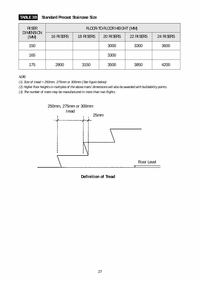
TABLE 3B Standard Precast Staircase Size
FLOOR-TO-FLOOR HEIGHT (MM)
16 RISERS 18 RISERS 20 RISERS 22 RISERS 24 RISERS
150 3000 3300 3600
165 3300
175 2800 3150 3500 3850 4200
RISERDIMENSION
(MM)
NOTE:
(1) Size of tread = 250mm, 275mm or 300mm (See figure below)
(2) Higher floor heights in multiples of the above risers’ dimensions will also be awarded with buildability points.
(3) The number of risers may be manufactured in more than two flights.
Definition of Tread
250mm, 275mm or 300mmtread
25mm
Floor Level
27

34
Typical Floor Plan
Apartment area per floor= 166.85 x 4= 667.4m2
Lift Lobby area per floor= 86.6m2
Typical floor area= 667.4 + 86.6= 754.0m2
3.0 EXAMPLES ON COMPUTING BUILDABILITY SCORE
3.1 A SINGLE BLOCK BUILDING PROJECT
A. Project Information• 1 block of 10-storey high residential apartment• No basement• Roof is of RC construction• 4 apartment per storey• For simplicity, assume typical floor layout for each floor, except 1st storey and
roof• Assume floor-to-floor height of 3.3m, except 1st storey, which is 4m high• For area of building:
Total floor area of Apartments = 10 x 667.40m2 6,674.0m2
Total floor area of Lift Lobby = 10 x 86.6m2 866.0m2
Roof area (assume same as typical floor) 754.0m2
Ast : Total floor area of building including roof area 8,294.0m2
B. Buildability Score FormulaBS = 50[∑(As x Ss)] + 30[∑(Aw x Sw)] + N
28

35
Typical Apartment Structural Floor Plan for Design Option 2 and Option 3
C. Different Design OptionsConsider four design options:Option 1: Design based on conventional RC frame structure with external and internal
brickwalls.
Option 2: Flat plate with cast in-situ columns design with external brickwalls andinternal precision block partitions.
Option 3: Flat plate with cast in-situ columns design with precast external walls andinternal precision block partitions.
Option 4: Design based on RC structure with cast in-situ columns, precast beams andprecast slabs with external brickwalls and internal precision block partitions.
29

36
Structural System(1) Cast in-situ slab with the value of 7,540.0 91 SS = 0.65 29.6
slab area over number of beamsgreater than 10Asa = 10 x 754.0 = 7,540m2,Ast = 8,294m2
(2) RC flat roof 754.0 9 SS = 0.65 2.9
Total (a) 8,294.0 100 32.5
Wall System(1) Windows & doors area 1,675.0 25 Sw = 1.00 7.5(2) Brickwall with plaster & paint finish 5,025.0 75 Sw = 0.40 9.0
Total (b) 6,700.0 100 16.5
Other Buildable Features(1) Standardisation of columns 3S at 90% 90 N = 2.0(2) Standardisation of beams 3S at 85% 85 N = 2.0(3) Standardisation of door 3S at 95% 95 N = 1.0
leaf openings (width)(4) Standardisation of 3S at 95% 95 N = 1.0
windows(5) Repetition of horizontal 75% 75 N = 1.0
grids (1M)(3 most common dimensions)
(6) Repetition of floor-to-floor 90% 90 N = 2.0height (0.5M)
(7) Vertical repetition of 82% 82 N = 2.0structural floor layout
(8) Ground beams on top of 85% 85 N = 0.5pilecaps
Total (c) 11.5
Buildability Score of Project (a) + (b) + (c) 61
OPTION 1Design based on conventional RC frame structure with external and internal brickwalls.
DESCRIPTION AREA(M2)
COVERAGE(%)
BUILDABILITYSCORE
LABOURSAVINGINDEX
30
37
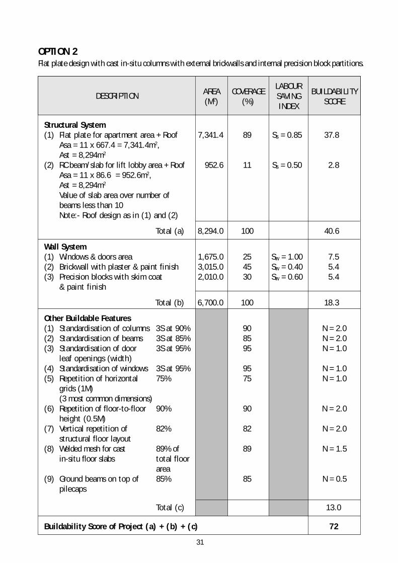
OPTION 2Flat plate design with cast in-situ columns with external brickwalls and internal precision block partitions.
Structural System(1) Flat plate for apartment area + Roof 7,341.4 89 Ss = 0.85 37.8
Asa = 11 x 667.4 = 7,341.4m2,Ast = 8,294m2
(2) RC beam/slab for lift lobby area + Roof 952.6 11 Ss = 0.50 2.8Asa = 11 x 86.6 = 952.6m2,Ast = 8,294m2
Value of slab area over number ofbeams less than 10Note:- Roof design as in (1) and (2)
Total (a) 8,294.0 100 40.6
Wall System(1) Windows & doors area 1,675.0 25 Sw = 1.00 7.5(2) Brickwall with plaster & paint finish 3,015.0 45 Sw = 0.40 5.4(3) Precision blocks with skim coat 2,010.0 30 Sw = 0.60 5.4
& paint finish
Total (b) 6,700.0 100 18.3
Other Buildable Features(1) Standardisation of columns 3S at 90% 90 N = 2.0(2) Standardisation of beams 3S at 85% 85 N = 2.0(3) Standardisation of door 3S at 95% 95 N = 1.0
leaf openings (width)(4) Standardisation of windows 3S at 95% 95 N = 1.0(5) Repetition of horizontal 75% 75 N = 1.0
grids (1M)(3 most common dimensions)
(6) Repetition of floor-to-floor 90% 90 N = 2.0height (0.5M)
(7) Vertical repetition of 82% 82 N = 2.0structural floor layout
(8) Welded mesh for cast 89% of 89 N = 1.5in-situ floor slabs total floor
area(9) Ground beams on top of 85% 85 N = 0.5
pilecaps
Total (c) 13.0
Buildability Score of Project (a) + (b) + (c) 72
DESCRIPTION AREA(M2)
COVERAGE(%)
BUILDABILITYSCORE
LABOURSAVINGINDEX
31

38
OPTION 3Flat plate design with cast in-situ columns with precast external walls and internal precision blockspartitions.
Structural System(1) Flat plate for apartment area + Roof 7,341.4 89 Ss = 0.85 37.8
Asa = 11 x 667.4 = 7.341m2,Ast = 8,294m2
(2) RC beam/slab for lift lobby area + Roof 952.6 11 Ss = 0.50 2.8Asa = 11 x 86.6 = 952.6m2,Ast = 8,294m2
Value of slab area over number ofbeams less than 10
Note:- Roof design as in (1) and (2)
Total (a) 8,294.0 100 40.6
Wall System(1) Windows & doors area 1,675.0 25 Sw = 1.00 7.5(2) Precast concrete panel with paint finish 2,010.0 30 Sw = 0.85 7.7(3) Brickwall with plaster & paint finish 1,005.0 15 Sw = 0.40 1.8(4) Precision blocks with skim coat 2,010.0 30 Sw = 0.60 5.4
& paint finish
Total (b) 6,700.0 100 22.4
Other Buildable Features(1) Standardisation of columns 3S at 90% 90 N = 2.0(2) Standardisation of beams 3S at 85% 85 N = 2.0(3) Standardisation of door 3S at 95% 95 N = 1.0
leaf openings (width)(4) Standardisation of windows 3S at 95% 95 N = 1.0(5) Repetition of horizontal 75% 75 N = 1.0
grids (1M)(3 most common dimensions)
(6) Repetition of floor-to-floor 90% 90 N = 2.0height (0.5M)
(7) Vertical repetition of 82% 82 N = 2.0structural floor layout
(8) Welded mesh for cast 89% of 89 N = 1.5in-situ floor slabs total floor
area(9) Ground beams on top of 85% 85 N = 0.5
pilecaps
Total (c) 13.0
Buildability Score of Project (a) + (b) + (c) 76
DESCRIPTION AREA(M2)
COVERAGE(%)
BUILDABILITYSCORE
LABOURSAVINGINDEX
32

39
OPTION 4Design based on RC structure with cast in-situ columns, precast concrete beams and precast concreteslabs with external brickwalls and internal precision block partitions.
Structural System(1) PC concrete beam and PC concrete slab 7,540.0 91 Ss = 0.90 41.0(2) RC cast in-situ flat roof 754.0 9 Ss = 0.65 2.9
Value of slab area over number of beamsgreater than 10
Total (a) 8,294.0 100 43.9
Wall System(1) Windows & doors area 1,675.0 25 Sw = 1.00 7.5(2) Brickwall with plaster & paint finish 3,015.0 45 Sw = 0.40 5.4(3) Precision blocks with skim coat 2,010.0 30 Sw = 0.60 5.4
& paint finish
Total (b) 6,700.0 100 18.3
Other Buildable Features(1) Standardisation of columns 3S at 90% 90 N = 2.0(2) Standardisation of beams 3S at 85% 85 N = 2.0(3) Standardisation of door 3S at 100% 100 N = 1.0
leaf openings (width)(4) Standardisation of windows 3S at 100% 100 N = 1.0(5) Repetition of horizontal 75% 75 N = 1.0
grids (1M)(3 most common dimensions)
(6) Repetition of floor-to-floor 90% 90 N = 2.0height (0.5M)
(7) Vertical repetition of 82% 82 N = 2.0structural floor layout
(8) Standard precast staircase 90% 90 N = 2.0(9) Ground beams on top of 85% 85 N = 0.5
pilecaps
Total (c) 13.5
Buildability Score of Project (a) + (b) + (c) 76
DESCRIPTION AREA(M2)
COVERAGE(%)
BUILDABILITYSCORE
LABOURSAVINGINDEX
33

40
Layout plan for a multi-block building project
3.2 A MULTI-BLOCK BUILDING PROJECT
A. Project InformationThis project consists of 8 blocks of buildings:-• 3 blocks of 3-storey high workshop (Block A, B & C)• 2 blocks of 2-storey high workshop (Block D & E)• 1 block of 2-storey high multi-purpose hall ( Block F)• 1 block of 2-storey high classroom (Block G)• 1 block of 2-storey high classroom cum administration (Block H)
Ast, total floor area including roof (projected area), of each building is as below:• Block A, B & C Ast = 2,700m2 per building• Block D Ast = 3,000m2
• Block E Ast = 2,400m2
• Block F Ast = 2,600m2
• Block G Ast = 1,000m2
• Block H Ast = 3,600m2
Overall project Ast = 20,700m2
34

41
The design of the buildings is as follow:• Structural System: (1) Block A, B, C, D, E & F - cast in-situ flat plate
with metal roof on steel truss(2) Block G & H - cast in-situ beam & slab with the value
of slab area over number of beams is smaller than 10• Wall System: (1) All the blocks - 50% precast panel with paint
finishing, 30% windows & 20% brickwalls withplaster & paint finishing
• Other Buildable Features: (1) Repetition of horizontal grids 85% (3M)(3 most common dimensions) - All blocks except block H
(2) Standardised column sizes - 3S at 90%- All blocks except block H which achieves astandardisation of 3S at 85%
(3) Standardised beam sizes - 3S at 90%- All blocks except block H which achieves astandardisation of 3S at 85%
(4) Standardised preassembled staircase (min 85%)- Block A, B, C, D & E
(5) Welded mesh for cast in-situ floor slabs(min 85%)- All blocks
(6) Standardised door leaf openings (width) - 3S at 85%- All blocks
(7) Standardised window sizes - 3S at 85%- All blocks
(8) Ground beams sit on top of pilecaps (min 85%)- All blocks
B. Buildability ScoreThe Buildability Score (BS) for the respective blocks is as follows:• Block A : BS = 79.0 (Ast) bldg / (Ast) proj = 0.13• Block B : BS = 79.0 (Ast) bldg / (Ast) proj = 0.13• Block C : BS = 79.0 (Ast) bldg / (Ast) proj = 0.13• Block D : BS = 79.0 (Ast) bldg / (Ast) proj = 0.14• Block E : BS = 79.0 (Ast) bldg / (Ast) proj = 0.12• Block F : BS = 77.0 (Ast) bldg / (Ast) proj = 0.13• Block G : BS = 59.2 (Ast) bldg / (Ast) proj = 0.05• Block H : BS = 57.2 (Ast) bldg / (Ast) proj = 0.17
The Buildability Score of the project is computed as below:
BS proj = Sum of [BS bldg x (Ast) bldg / (Ast) proj]= 74
35

4236

43
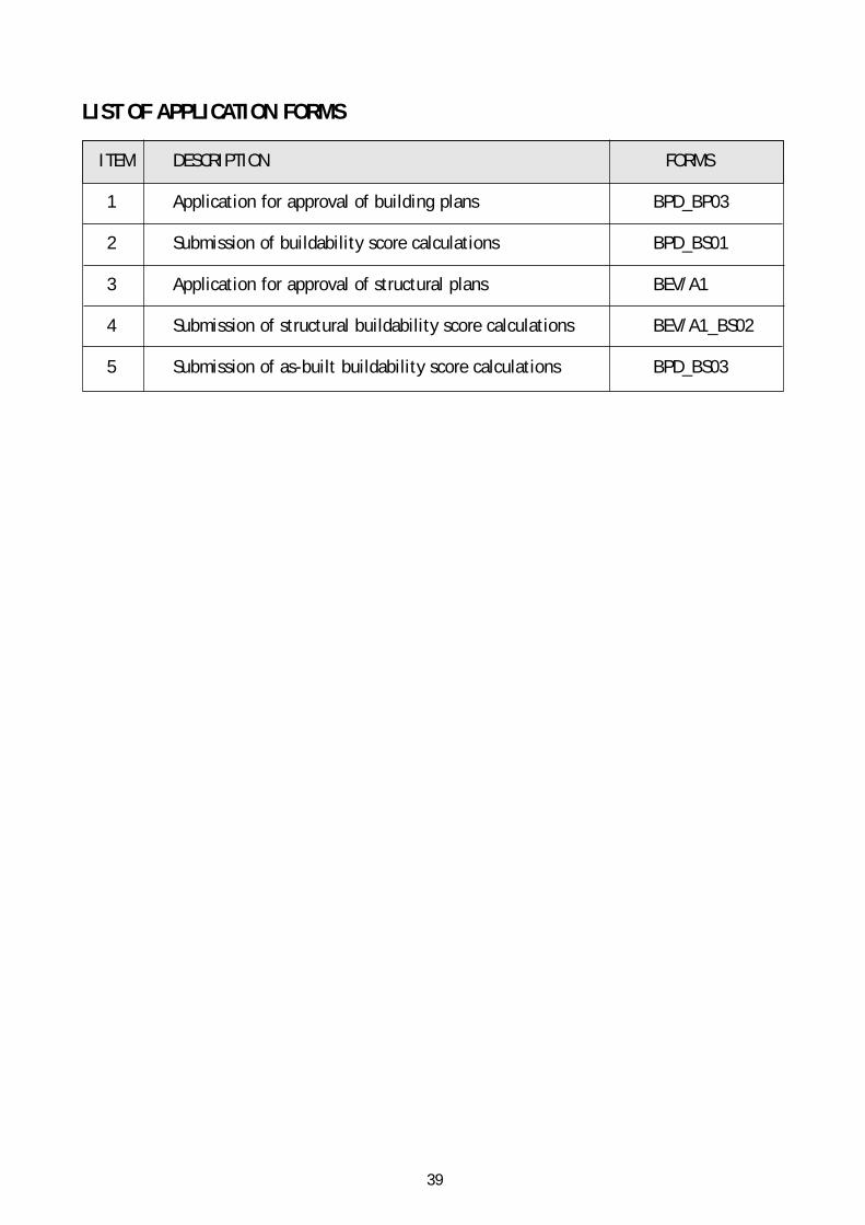
LIST OF APPLICATION FORMS
Annex B
37

4438
45
ITEM DESCRIPTION FORMS
1 Application for approval of building plans BPD_BP03
2 Submission of buildability score calculations BPD_BS01
3 Application for approval of structural plans BEV/A1
4 Submission of structural buildability score calculations BEV/A1_BS02
5 Submission of as-built buildability score calculations BPD_BS03
LIST OF APPLICATION FORMS
39
46BPD_BP03[Ver 2.2_Aug_2002]
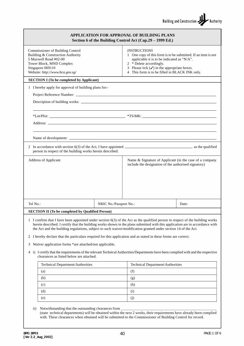
PAGE 1 OF 6
1 I hereby apply for approval of building plans for:-
Project Reference Number:
Description of building works:
*Lot/Plot: *TS/MK:
Address:
Name of development:
2 In accordance with section 6(3) of the Act, I have appointed as the qualifiedperson in respect of the building works herein described.
APPLICATION FOR APPROVAL OF BUILDING PLANSSection 6 of the Building Control Act (Cap.29 – 1999 Ed.)
Commissioner of Building ControlBuilding & Construction Authority5 Maxwell Road #02-00Tower Block, MND ComplexSingapore 069110Website: http://www.bca.gov.sg/
INSTRUCTIONS1 One copy of this form is to be submitted. If an item is not
applicable it is to be indicated as “N/A”.2 * Delete accordingly.3 Please tick (✓) in the appropriate boxes.4 This form is to be filled in BLACK INK only.
SECTION I (To be completed by Applicant)
Address of Applicant Name & Signature of Applicant (in the case of a companyinclude the designation of the authorised signatory)
Tel No.: NRIC No./Passport No.: Date:
SECTION II (To be completed by Qualified Person)
1 I confirm that I have been appointed under section 6(3) of the Act as the qualified person in respect of the building worksherein described. I certify that the building works shown in the plans submitted with this application are in accordance withthe Act and the building regulations, subject to such waiver/modification granted under section 14 of the Act.
2 I hereby declare that the particulars required for this application and as stated in these forms are correct.
3 Waiver application forms *are attached/not applicable.
4 i) I certify that the requirements of the relevant Technical Authorities/Departments have been complied with and the respectiveclearances as listed below are attached.
Technical Department/Authorities Technical Department/Authorities
(a) (f)
(b) (g)
(c) (h)
(d) (i)
(e) (j)
ii) Notwithstanding that the outstanding clearances from ___________________________________________________(state technical departments) will be obtained within the next 2 weeks, their requirements have already been compliedwith. These clearances when obtained will be submitted to the Commissioner of Building Control for record.
40

47BPD_BP03[Ver 2.2_Aug_2002]
PAGE 2 OF 6
5 I confirm that -
i) planning permission for the building works is not applicable;
ii) the building works have been submitted to the Chief Planner, Urban Redevelopment Authority under the lodgementscheme; or
iii) planning permission for the building works is applicable and has been granted by the Competent Authority. Thewritten permission *together with the approved site plan ( ) in DC ___________________________ isattached/is granted under electronic submission.
I hereby declare that (if item (ii) or (iii) is ticked):
(a) the building plans do not deviate from the plan submitted to URA as lodgement under SubmissionNo: __________________________;
(b) the building plans do not deviate from *approved plan ( ) in DC ___________________________________________/Electronic submission approval no: ________________________________;
(c) the building plans contain minor deviations from *approved plan ( ) in DC ________________________________/Electronic submission approval no: ________________________________.These minor deviations are covered in the list of items exempted from Planning Permission as issued bythe Competent Authority.
(d) the building plans contain minor deviations from *approved plan ( ) in DC ___________________________________/Electronic submission approval no: ________________________________.These minor deviations, although not specifically exempted from planning permission, do not give riseto additional GFA beyond the approved GFA nor do they attract additional development charge ordifferential premium (whichever is applicable). The minor deviations have also not departed from theplanning controls on building setback, overall building height (amsl), floor-to-floor height, site coverage,platform level, use quantum and height of basement protrusion.
6 I confirm that household/storey shelter work is -
i) not applicable and the reason(s) being (tick as appropriate):
(a) there is no residential dwelling in the building works.
(b) application for planning permission for the building works was submitted to URA before 1 May 98 andURA’s planning permission has not lapsed or become invalid.
(c) building works involve additions and alterations where there is no household/storey shelter or whereaddition & alteration works do not affect the existing household/storey shelter.
(d) reconstruction not involving a total demolition of existing residential building.
ii) applicable and I will obtain Notice of Acceptance of shelter plans from Special Functions Division of BCA.
7 The building works have *not commenced/commenced on _______________ (date) *with/without a permit to carry outbuilding works.
8 OTTV plans and calculations are -
i) not applicable;
ii) applicable and a set of these calculations are attached.
9 Buildable design calculations are -
i) not applicable, the reason being: gross floor area less than 5000m2. [Regulation 3(2) of the BuildingControl (Buildable Design) Regulations (Cap 29)]
waiver obtained.
exempted under Regulation 3(3) of the Building Control(Buildable Design) Regulations.
buildability score submitted in the previous BP submission. There isno change to the buildability score declared previously.
application for planning permission for the building works was madebefore 1 January 2001.
41

48BPD_BP03[Ver 2.2_Aug_2002]
PAGE 3 OF 6
Address of Qualified Person Name & Signature of Qualified Person
ii) applicable and a set of these calculations (Form BPD_BS01) is attached. The buildability score is________________ . The 1st application for planning permission for the building works was made on:
1st Jan 2001 - 31st July 2002
on or after 1st Aug 2002
10 The information related to buildability score is given below ( tick as appropriate):i) Gross floor area of proposed building:-
≥ 5000m2 but lessthan 25000m2 ≥ 25000m2
ii) Category of building (for mixed developments, more than 1 box may be ticked)
11 Other documents necessary for the consideration of approval of the building plans are attached herewith.
Tel No.: Fax No.: Reg No. (*Arch/PE): Date:
Residential (landed) Residential (non-landed) Commercial
Industrial Institutional and others
42
49BPD_BP03_Appendix[Ver 2.2_Aug_2002]
PAGE 4 OF 6
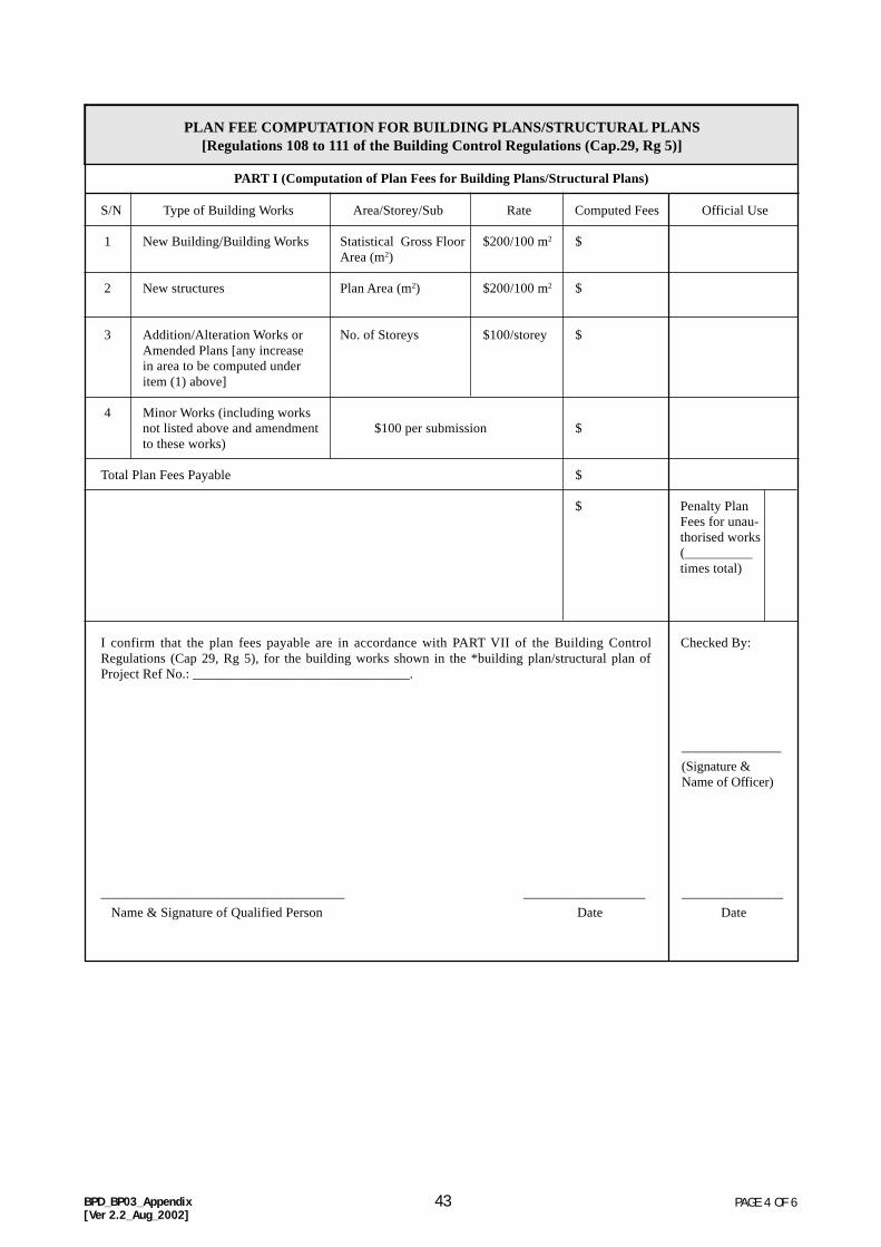
PLAN FEE COMPUTATION FOR BUILDING PLANS/STRUCTURAL PLANS[Regulations 108 to 111 of the Building Control Regulations (Cap.29, Rg 5)]
PART I (Computation of Plan Fees for Building Plans/Structural Plans)
S/N Type of Building Works Area/Storey/Sub Rate Computed Fees Official Use
1 New Building/Building Works Statistical Gross Floor $200/100 m2 $Area (m2)
2 New structures Plan Area (m2) $200/100 m2 $
3 Addition/Alteration Works or No. of Storeys $100/storey $Amended Plans [any increasein area to be computed underitem (1) above]
4 Minor Works (including worksnot listed above and amendment $100 per submission $to these works)
Total Plan Fees Payable $
$ Penalty PlanFees for unau-thorised works(__________times total)
I confirm that the plan fees payable are in accordance with PART VII of the Building ControlRegulations (Cap 29, Rg 5), for the building works shown in the *building plan/structural plan ofProject Ref No.: ________________________________.
____________________________________ __________________
Name & Signature of Qualified Person Date
Checked By:
_______________
(Signature &Name of Officer)
_______________
Date
43
50 PAGE 5 OF 6
EXPLANATORY NOTES TO FORM BPD_BP03 & FORM BPD_BP03 APPENDIX 1
(A) APPLICATION FORM
(1) Every application shall be accompanied by -(a) 1 set of building plans with the project reference number printed at the top right-hand corner on
every sheet of the plans and one copy of the site plan drawn in accordance with the provisions of theRegulations (scale between 1:200 to 1:1000);
(b) Where applicable, an application(s) for the Modification/Waiver of Building Regulations - FormBPD_BP05; and
(c) Where applicable, the Written Permission (Notice of Grant of Approval) including only the site planapproved by the Competent Authority under Planning Act (Development Control Division, URA).
(d) Clearances from the relevant technical authorities/departments.(e) Where applicable, OTTV submission form (Form BPD_BP04), plans and calculations.
(2) The plans for building works shall be prepared in accordance with the relevant provisions in Part II of theBuilding Control Regulations.
(3) The Qualified Person appointed under Section 6(3) of the Act shall be according to the type of projects orbuilding works as determined under the First Schedule to the Building Control Regulations.
(4) The Qualified Person who prepares the building plans shall certify on every sheet of the drawings asfollows:-
“I, ________________________ hereby certify, subject to any waiver/modification granted under Section14 of the Act, that the preparation of these building plans and the building works shown on these plans arestrictly in accordance with the provisions of the Building Control Act (Cap 29) and the Regulations madethereunder”.
____________________________________ _____________________ Signature of Qualified Person Date
(5) In the case of any building plans for repairs, alterations or additions to an existing building issued with a Certificateof Statutory Completion or a Temporary Occupation Permit -
Where the Qualified Person who prepares the building plans reasonably suspects that the building worksmay affect the structural stability or integrity of the building, every sheet of the drawings shall bear acertificate from a Professional Engineer (Civil) or (Structural) as follows:-
“I have inspected the building and investigated its overall structure and that, in my opinion, the building iscapable of resisting the forces and moments which may be increased or altered by reason of the repairs, alterationsor additions shown on these plans”.
____________________________________ _____________________Stamp & Signature of Professional Engineer Date
BPD_BP03_Explanatory Notes[Ver 2.2_Aug_2002]
44

51BPD_BP03_Explanatory Notes[Ver 2.2_Aug_2002]
PAGE 6 OF 6
OR
“I have inspected the building and investigated its overall structure and that, in my opinion, the building withits structural elements strengthened in accordance with the structural plans *submitted on _____________/tobe submitted for approval before submission of the Joint Application For Permit To Commence *Piling/Structural/Building Works, will be capable of resisting the forces and moments which may be increased oraltered by reason of the repairs, alterations or additions shown on these plans”.
____________________________________ _____________________Stamp & Signature of Professional Engineer Date
(6) Building developments with Provisional Permissions (“PPs”) issued before 15 September 2000, are requiredto comply with the Singapore Broadcasting Authority (“SBA”)’s directions and recommendations concerningthe installation and provision of cable-ready Master Antenna Television (MATV) system.
Building developments with Provisional Permissions issued on and after 15 September 2000, are requiredto comply with the Info-communications Development Authority of Singapore (“IDA”)’s directions andrecommendations in accordance with the Code of Practice for Info-Communications Facilities in Buildings(“COPIF”). For buildings, which are six storeys and above, developers are also required to comply withthe “tap off-pipes” directions issued by SBA.
A letter from the Qualified Person indicating receipt and retention of Singapore Cable Vision’s Certificateof Cable Readiness must be submitted before the issuance of the Certificate of Statutory Completion.
(B) FEE COMPUTATION FORMAT (APPENDIX 1)
(1) One copy of this form is to be submitted.
(2) Payment of fees shall preferably be made by cheque in favour of the “BUILDING & CONSTRUCTIONAUTHORITY, SINGAPORE”.
(3) The statistical gross floor area (SGFA) means the aggregate of the “gross floor areas” and “other areas”.
(4) A certified true copy of forms submitted to URA Development Control Division on the Statistical GrossFloor Area (PR 16G) is to be attached for the purpose of confirming building plan fees. Please ensure thatPR 16G also reflects other areas such as carpark, swimming pool and others.
(5) If alterations to an existing building or amendments to an approved plan under S/N (3) involve an increasein the floor area, the fee for the new area shall be computed according to S/N (1).
45
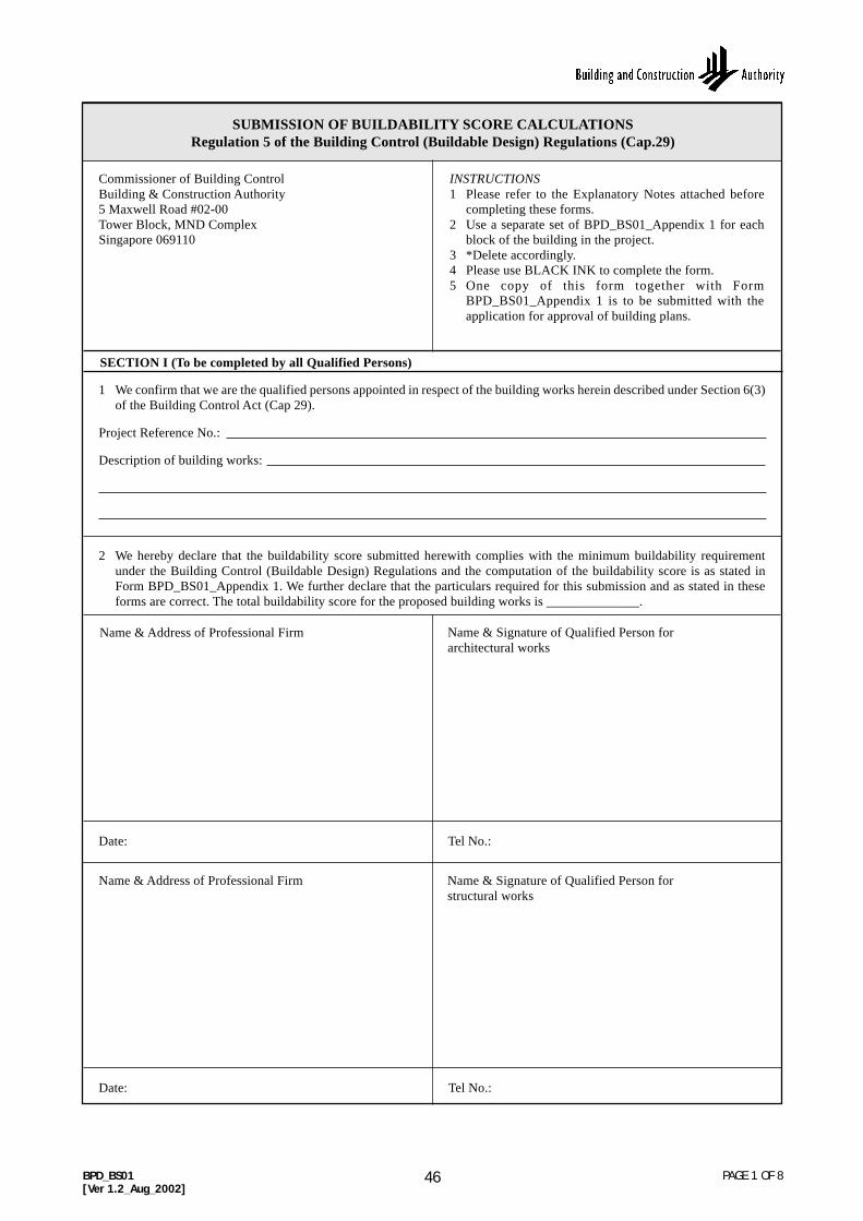
52BPD_BS01[Ver 1.2_Aug_2002]
SUBMISSION OF BUILDABILITY SCORE CALCULATIONSRegulation 5 of the Building Control (Buildable Design) Regulations (Cap.29)
Commissioner of Building ControlBuilding & Construction Authority5 Maxwell Road #02-00Tower Block, MND ComplexSingapore 069110
INSTRUCTIONS1 Please refer to the Explanatory Notes attached before
completing these forms.2 Use a separate set of BPD_BS01_Appendix 1 for each
block of the building in the project.3 *Delete accordingly.4 Please use BLACK INK to complete the form.5 One copy of this form together with Form
BPD_BS01_Appendix 1 is to be submitted with theapplication for approval of building plans.
SECTION I (To be completed by all Qualified Persons)
1 We confirm that we are the qualified persons appointed in respect of the building works herein described under Section 6(3)of the Building Control Act (Cap 29).
Project Reference No.:
Description of building works:
2 We hereby declare that the buildability score submitted herewith complies with the minimum buildability requirementunder the Building Control (Buildable Design) Regulations and the computation of the buildability score is as stated inForm BPD_BS01_Appendix 1. We further declare that the particulars required for this submission and as stated in theseforms are correct. The total buildability score for the proposed building works is ______________.
Name & Address of Professional Firm Name & Signature of Qualified Person forarchitectural works
Date: Tel No.:
Name & Address of Professional Firm Name & Signature of Qualified Person forstructural works
Date: Tel No.:
PAGE 1 OF 846

53
STRUCTURAL SYSTEMAREA(M2)(a)
% AREA(b)
BUILDABILITYSCORE
(b) x (c) x 50
LABOURSAVING
INDEX (c)
BPD_BS01_Appendix 1[Ver 1.2_Aug_2002]
CALCULATIONS OF OVERALL BUILDABILITY SCORERegulation 5 of the Building Control (Buildable Design) Regulations (Cap.29)
PART I : PROJECT DETAILS
Project Reference No.:
Block No./Name: Total no. of blocks:
Please indicate other typical blocks (if any):
PART II : COMPUTATION OF BUILDABILITY SCORE
PAGE 2 OF 8
1 STEEL BEAM
1.1 Steel beam with column in sprayed fire proofed with:
1.1.1 cast-in-place slab on steel decking 0.95
1.1.2 precast concrete slab 0.90
1.2 Steel beam with column encased in concrete with:
1.2.1 cast-in-place slab on steel decking 0.85
1.2.2 precast concrete slab 0.80
2 PRECAST CONCRETE BEAM
2.1 with precast column/wall with precast concrete slab 1.00
2.2 with cast in-situ column/wall with precast concrete slab 0.90
3 NO INTERNAL BEAM
3.1 with precast column/wall
3.1.1a with flat plate (post-tensioned/prestressed) 0.95
3.1.1b with flat plate (without post-tensioned/prestressed) 0.90
3.2 with cast in-situ column/wall
3.2.1a with flat plate (post-tensioned/prestressed) 0.90
3.2.1b with flat plate (without post-tensioned/prestressed) 0.85
3.2.2a with flat slab (post-tensioned/prestressed) 0.85
3.2.2b with flat slab (without post-tensioned/prestressed) 0.80
Category of Building (for mixed development, more than 1 box may be ticked):
Residential (landed) Residential (non-landed) Commercial
Industrial Institutional & others
For mixed development, please indicate the GFA for each category:
Residential (landed) m2
Residential (non-landed) m2
Commercial m2
Industrial m2
Institutional & others m2
47

54BPD_BS01_Appendix 1[Ver 1.2_Aug_2002]
PAGE 3 OF 8
AREA(M 2)(a)
% AREA(b)
BUILDABILITYSCORE
(b) x (c) x 50
LABOURSAVING
INDEX (c)STRUCTURAL SYSTEM
4 CAST IN-SITU BEAM AND COLUMN/WALL
4.1 precast concrete slab (without transfer beams)(slab/beam>10) with:
4.1.1a cast in-situ beams (post-tensioned/ prestressed) 0.75
4.1.1b cast in-situ beams (without post-tensioned/ prestressed) 0.70
4.2 precast concrete slab (without transfer beams)(slab/beam≤10) with:
4.2.1a cast in-situ beams (post-tensioned/ prestressed) 0.65
4.2.1b cast in-situ beams (without post-tensioned/ prestressed) 0.60
4.3 cast in-situ slab (without transfer beams) (slab/beam >10) with:
4.3.1a 1-way banded beam with slabs/beams 0.75(post-tensioned/prestressed)
4.3.1b 1-way banded beam with slabs/beams 0.70(without post-tensioned/prestressed)
4.3.2a 2-way beam with slabs/beams 0.70(post-tensioned/prestressed)
4.3.2b 2-way beam with slabs/beams 0.65(without post-tensioned/prestressed)
4.4 cast in-situ slab (without transfer beams)(slab/beam ≤ 10) with:
4.4.1a slabs/beams (post-tensioned/prestressed) 0.55
4.4.1b slabs/beams (without post-tensioned/prestressed) 0.50
4.5 cast in-situ slabs (with transfer beams)- applicable to projects submitted for planning approval 0.40on or after 1st Aug 2002 only
5 ROOF SYSTEM
5.1 Integrated metal roof on steel truss 0.90
5.2 Metal roof on steel truss 0.85
5.3 Tiled roof on steel beam or PC concrete beam or timber 0.75beam
5.4 Tiled roof with cast in-situ beam 0.55
5.5 Concrete roof (constructed area shall be includedin the slab design above)
6 OTHER STRUCTURAL SYSTEMS NOT LISTED IN BDAS
Sub-total for structural system (A)(maximum 50 points)
Total floor area including roof area
48

55
WALL SYSTEMAREA(M 2)(a)
% AREA(b)
BUILDABILITYSCORE
(b) x (c) x 30
LABOURSAVING
INDEX (c)
BPD_BS01_Appendix 1[Ver 1.2_Aug_2002]
PAGE 4 OF 8
1 WINDOWS/DOORS/PREFABRICATED RAILINGS 1.00
2 CURTAIN WALL/FULL HEIGHT GLASS PARTITION
2.1 No finishes/pre-finished 1.00
3 PRECAST CONCRETE PANEL/ WALL (includes normal weight concrete panels, lightweight concrete panels,autoclaved aerated concrete panels)
3.1 No finishes/pre-finished 0.95
3.2 With paint finish 0.85
3.3 With skim coat & paint finish 0.80
3.4 With tiled/stone finish (tile/stone pre-installed in factory) 0.95
3.5 With tiled/stone finish (tile/stone installed at site) 0.60
4 DRY INTERNAL WALLS (include sandwich panel wall system, stud and sheet partition wall systems,demountable wall systems)
4.1 No finishes/pre-finished 1.00
4.2 With paint finish 0.90
4.3 With tiled/stone finish 0.65
5 PC FORMWORK
5.1 With no finishes/pre-finished 0.80
5.2 With paint finish 0.70
5.3 With skim coat and paint finish 0.60
5.4 With tiled/stone finish 0.50
6 PRECISION BLOCKWALL
6.1 With skim coat and paint finish 0.60
6.2 With tiled/stone finish 0.50
6.3 With metal/plasterboard cladding 0.80
7 CAST IN-SITU RC WALL
7.1 With no finishes/pre-finished 0.75
7.2 With paint finish 0.65
7.3 With skim coat and paint finish 0.55
7.4 With plaster & paint finish 0.50
7.5 With tiled/stone finish 0.45
7.6 With metal/plasterboard cladding 0.70
8 BRICKWALL
8.1 Brickwall
8.1a with plaster & paint finish 0.40
8.1b with tiled/stone finish 0.35
8.1c with metal/plasterboard cladding 0.50
8.2 Half fair-faced wall with no finishes/pre-finished 0.40
8.3 Full fair-faced/glass block wall with no finishes/pre-finished 0.30
49

56
UNIT OF COVERAGEBUILDABLE FEATURES MODULE BUILDA BILITY
SCORE
VALUE FORTHIS PROJECT
IN %≥65%-<80% ≥80%
WALL SYSTEMAREA(M2)(a)
% AREA(b)
BUILDABILITYSCORE
(b) x (c) x 30
LABOURSAVING
INDEX (c)
BPD_BS01_Appendix 1[Ver 1.2_Aug_2002]
PAGE 5 OF 8
9 OTHER WALL SYSTEMS NOT LISTED IN BDAS
Total wall area (external wall area and internal wall area)
Sub-total for wall system (B)(maximum 30 points)
1 STANDARDISATION
1.1 Columns (3 most common sizes) 0.5M N.A. 2.00- in nos.
1.2 Beams (3 most common sizes) 0.5M N.A. 2.00- in nos.
1.3 (a) Standard door leaf openings (width) (3 most common sizes) N.A. 0.50 1.00 (see Table 3A) - in nos.
OR
(b) Standard door leaf openings (width) and standard structural openings (3 most common N.A. 1.00 2.00 sizes) (see Table 3A) - in nos.
OR
(c) Standard structural openings for doors (3 most common sizes) (for sizes not within the range 2M or 3M 0.50 1.00 stipulated in Table 3A) - in nos.
1.4 Windows (3 most common 1M/1M 0.50 1.00sizes) - in nos.
2 GRIDS
2.1 (a)Repetition of horizontal grids(between supports) (3 most 1M 1.00 1.50common dimensions) - in nos.
OR
(b)Repetition of horizontal grids(between supports) (3 most 3M 1.50 2.00common dimensions) - in nos.
2.2 Repetition of floor-to-floor 0.5M 1.00 2.00height - in nos.
2.3 Vertical repetition of structural N.A. 1.50 2.00floor layout - in areas
3 PREFABRICATED REINFORCEMENT
3.1 Floor - in areas N.A. 1.00 1.50
3.2 Wall - in areas N.A. 1.00 1.50
3.3 Beam cage - in nos. N.A. 1.50 2.00
3.4 Column cage - in nos. N.A. 1.50 2.00
50

57BPD_BS01_Appendix 1[Ver 1.2_Aug_2002]
PAGE 6 OF 8
UNIT OF COVERAGEBUILDABLE FEATURES MODULE BUILDA BILITY
SCORE
VALUE FORTHIS PROJECT
IN %≥65%-<80% ≥80%
4 OTHERS
4.1 (a) Prefabricated bathroom/toilet complete with piping/wiring: 0.5M 1.50 2.00 prefabricated wall panels and floor tray separately assembled - in nos.
OR(b) Prefabricated bathroom/toilet
complete with piping/wiring: full prefabricated cell completed 0.5M 2.00 3.00 with finished wall and floor - in nos.
4.2 (a) Standard precast staircase N.A. N.A. 2.00 (see Table 3B) - in nos.
OR(b ) Pre-assembled/metal staircaseN.A. N.A. 2.00
- in nos.4.3 Prefabricated vertical shafts N.A. N.A. 1.00
(e.g. refuse chutes) - in nos.
4.4 Multi-tier precast columns - in nos. N.A. N.A. 2.00
Sub-total for other buildable design features (C)(maximum 20 points)
GRAND TOTAL (A + B + C)
4.5 (a) Precast CD shelters: minimum 0.5M 1.00 1.50 2 panels precast - in nos.
OR
(b) Precast CD shelters: 0.5M 2.00 3.00 full precast cells - in nos.
4.6 Non-screed floor - in areas N.A. N.A. 1.00
4.7 Columns sit directly on top of piles N.A. N.A. 0.50- in nos.
4.8 Ground beams on top of pilecapsN.A. N.A. 0.50- in nos.
4.9 Diaphragm wall construction N.A. N.A. 1.50- in areas
5 OTHER BUILDABLE FEATURES NOT LISTED IN BDAS
51

58BPD_BS01_Appendix 1[Ver 1.2_Aug_2002]
PAGE 7 OF 8
BLOCK NO./NAMEFLOOR AREA
(M 2)(a)
PERCENTAGEOF FLOORAREA (b)
APPORTIONATEBUILDABILITY
SCORE(b) x (c)
BUILDABILITYSCORE
(c)
PART III : SUMMARY SHEET (For multiple-block building projects)
TOTAL
TOTAL BUILDABILITY SCORE FOR THIS PROJECT = ____________________
52
59 PAGE 8 OF 8
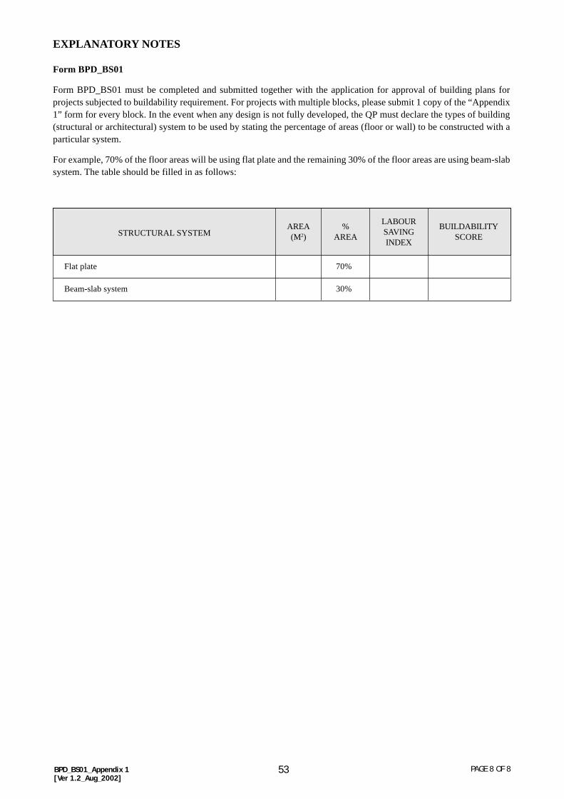
EXPLANATORY NOTES
Form BPD_BS01
Form BPD_BS01 must be completed and submitted together with the application for approval of building plans forprojects subjected to buildability requirement. For projects with multiple blocks, please submit 1 copy of the “Appendix1” form for every block. In the event when any design is not fully developed, the QP must declare the types of building(structural or architectural) system to be used by stating the percentage of areas (floor or wall) to be constructed with aparticular system.
For example, 70% of the floor areas will be using flat plate and the remaining 30% of the floor areas are using beam-slabsystem. The table should be filled in as follows:
Flat plate 70%
Beam-slab system 30%
STRUCTURAL SYSTEMAREA(M2)
%AREA
BUILDABILITYSCORE
LABOURSAVINGINDEX
BPD_BS01_Appendix 1[Ver 1.2_Aug_2002]
53

60BEV/A1[Ver 1.1_Aug_2002]
PAGE 1 OF 2
1 I hereby apply for approval of the *site formation/piling/structural plans and calculations for:
Project Reference No.:
Project Title:
*Lot/Plot: *TS/MK:
House No: Road:
APPLICATION FOR APPROVAL OF STRUCTURAL PLANSSection 6(1) of the Building Control Act (Cap.29)
Commissioner of Building ControlBuilding and Construction Authority5 Maxwell Road #02-00Tower Block, MND ComplexSingapore 069110
SECTION I (To be completed by Applicant)
2 Classification of Works Type of Works Usage
New developments Site formation Residential (landed)
A/A works Piling works Residential (non-landed)
Retention works Sub-structural works Commercial
Super-structural works Institutional
Number of Storeys:_______________ Cladding/Curtain Wall Bridge/Jetty
Value of BuildingWorks:___________ Retaining wall Industrial
3 The Plans are
structural plans of project ref. no.: ______________________________________________________________
amendment plans to structural plans of project ref. no.: _________________________ ST________________
the first plans to be submitted under this project and building plan submission will be made subsequently
the first plans to be submitted under this project and building plan submission is inapplicable
4 Before making this application, under the Building Control Act, I had appointed the following:
(a) Qualified Person for structural works
Name: ________________________________________ , PE Registration No.: ___________________________
(b) Accredited Checker (AC):
(i) AC in an Accredited Checking Organisation (ACO):
Name of AC ____________________________________ , AC Registration No.:__________________________
Name of ACO ___________________________________ , ACO Registration No.:_________________________or(ii) AC acting on his own behalf & not in an ACO:
Name of AC _____________________________________ , AC Registration No.:_________________________
(Note: Fill either (b)(i) or (ii) as appropriate and note that for (b)(ii), AC not in an ACO is restricted to undertakework in a project with a value of building works up to $10 million)
5 I confirm that the works on the proposal
have not commenced
were commenced on ______________ *with/without the prior permit of the Commissioner of Building Control
Name & Address of Applicant Name & Designation of authorised signatory(if applicant is a company)
Tel No.:______________________ Date:______________
Signature: _______________________________________
NRIC No.: _______________________________________
INSTRUCTIONS1 This Form is to be completed for AC and Non-AC Projects.2 Tick the appropriate box.3 * Delete accordingly.4 Please use BLACK INK to complete the form.
Note - Guidelines for Submission of Structural Plans andCalculations BEV/A1-GUIDELINE are available at BCAService Counter.
54
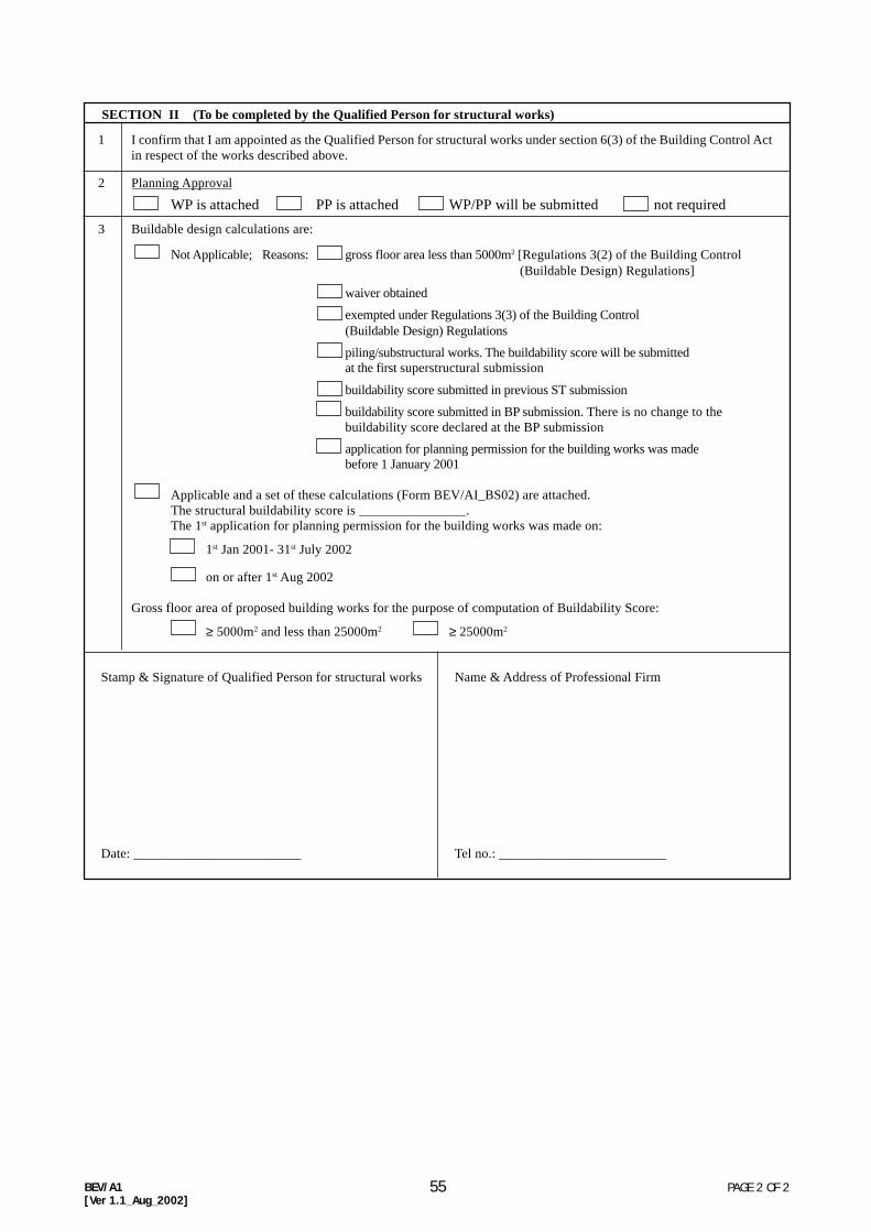
61BEV/A1[Ver 1.1_Aug_2002]
PAGE 2 OF 2
SECTION II (To be completed by the Qualified Person for structural works)
1 I confirm that I am appointed as the Qualified Person for structural works under section 6(3) of the Building Control Actin respect of the works described above.
2 Planning Approval
WP is attached PP is attached WP/PP will be submitted not required
3 Buildable design calculations are:
Not Applicable; Reasons: gross floor area less than 5000m2 [Regulations 3(2) of the Building Control(Buildable Design) Regulations]
waiver obtained
exempted under Regulations 3(3) of the Building Control(Buildable Design) Regulations
piling/substructural works. The buildability score will be submittedat the first superstructural submission
buildability score submitted in previous ST submission
buildability score submitted in BP submission. There is no change to thebuildability score declared at the BP submission
application for planning permission for the building works was madebefore 1 January 2001
Applicable and a set of these calculations (Form BEV/AI_BS02) are attached.The structural buildability score is ________________.The 1st application for planning permission for the building works was made on:
1st Jan 2001- 31st July 2002
on or after 1st Aug 2002
Gross floor area of proposed building works for the purpose of computation of Buildability Score:
≥ 5000m2 and less than 25000m2 ≥ 25000m2
Tel no.: _________________________
Stamp & Signature of Qualified Person for structural works Name & Address of Professional Firm
Date: _________________________
55

62BEV/A1_BS02[Ver 1.2_Aug_2002]
SUBMISSION OF STRUCTURAL BUILDABILITY SCORE CALCULATIONSRegulation 6 of the Building Control (Buildable Design) Regulations (Cap.29)
Commissioner of Building ControlBuilding & Construction Authority5 Maxwell Road #02-00Tower Block, MND ComplexSingapore 069110
INSTRUCTIONS1 Please refer to the Explanatory Notes attached before
completing these forms.2 Use a separate set of BEV/A1_BS02_Appendix 1 for each
block of the building in the project.3 *Delete accordingly.4 Please use BLACK INK to complete the form.5 One copy of this form is to be submitted at the first
submission for superstructural works.
SECTION I (To be completed by the Qualified Person for structural works)
I hereby submit the provisional buildability scores of the structural works for the project described herein and BEV/A1_BS02_Appendix 1 is attached.
Project Reference No.:
Description of building works:
Buildability score of structural works:
The overall buildability score for the above project shall be submitted at the application for approval of building plans.
Name & Address of Professional Firm Name & Signature of Qualified Person forstructural works
Date: Tel No.:
SECTION II (To be completed by the Qualified Person for architectural works)
I have noted the buildability score of the structural works submitted by the Qualified Person for Structural Works.
The overall buildability score for the above project shall be submitted at the application for approval of building plans.
Name & Address of Professional Firm Name & Signature of Qualified Person forarchitectural works
Date: Tel No.:
PAGE 1 OF 756

63BEV/A1_BS02_Appendix 1[Ver 1.2_Aug_2002]
PAGE 2 OF 7
STRUCTURAL SYSTEMAREA(M 2)(a)
% AREA(b)
BUILDABILITYSCORE
(b) x (c) x 50
LABOURSAVING
INDEX (c)
CALCULATIONS OF STRUCTURAL BUILDABILITY SCORERegulation 6 of the Building Control (Buildable Design) Regulations (Cap.29)
PART I : PROJECT DETAILS
Project Reference No.:
Block No./Name: Total no. of blocks:
Please indicate other typical blocks (if any):
Category of Building (for mixed development, more than 1 box may be ticked):
Residential (landed) Residential (non-landed) Commercial
Industrial Institutional & others
For mixed development, please indicate the GFA for each category:
Residential (landed) m2
Residential (non-landed) m2
Commercial m2
Industrial m2
Institutional & others m2
PART II : COMPUTATION OF BUILDABILITY SCORE
1 STEEL BEAM
1.1 Steel beam with column in sprayed fire proofed with:
1.1.1 cast-in-place slab on steel decking 0.95
1.1.2 precast concrete slab 0.90
1.2 Steel beam with column encased in concrete with:
1.2.1 cast-in-place slab on steel decking 0.85
1.2.2 precast concrete slab 0.80
2 PRECAST CONCRETE BEAM
2.1 with precast column/wall with precast concrete slab 1.00
2.2 with in-situ cast column/wall with precast concrete slab 0.90
3 NO INTERNAL BEAM
3.1 with precast column/wall
3.1.1a with flat plate (post-tensioned/prestressed) 0.95
3.1.1bwith flat plate (without post-tensioned/prestressed) 0.90
3.2 with cast in-situ column/wall
3.2.1a with flat plate (post-tensioned/prestressed) 0.90
3.2.1bwith flat plate (without post-tensioned/prestressed) 0.85
3.2.2a with flat slab (post-tensioned/prestressed) 0.85
3.2.2bwith flat slab (without post-tensioned/prestressed) 0.80
4 CAST IN-SITU BEAM AND COLUMN/WALL
4.1 precast concrete slab (without transfer beams)(slab/beam > 10) with:
4.1.1a cast in-situ beams (post-tensioned/prestressed) 0.75
4.1.1bcast in-situ beams (without post-tensioned/ prestressed) 0.70
57

64
AREA(M 2)(a)
% AREA(b)
BUILDABILITYSCORE
(b) x (c) x 50
LABOURSAVING
INDEX (c)STRUCTURAL SYSTEM
4.2 precast concrete slab (without transfer beams)(slab/beam ≤ 10) with:
4.2.1a cast in-situ beams (post-tensioned/prestressed) 0.65
4.2.1b cast in-situ beams (without post-tensioned/prestressed) 0.60
4.3 cast in-situ slab (without transfer beams) (slab/beam > 10) with:
4.3.1a 1-way banded beam with slabs/beams 0.75(post-tensioned/prestressed)
4.3.1b 1-way banded beam with slabs/beams 0.70(without post-tensioned/prestressed)
4.3.2a 2-way beam with slabs/beams 0.70(post-tensioned/prestressed)
4.3.2b 2-way beam with slabs/beams 0.65(without post-tensioned/prestressed)
4.4 cast in-situ slab (without transfer beams) (slab/beam ≤ 10) with:
4.4.1a slabs/beams (post-tensioned/prestressed) 0.55
4.4.1b slabs/beams (without post-tensioned/prestressed) 0.50
4.5 cast in-situ slabs (with transfer beams)- applicable to projects submitted for planning approval 0.40on or after 1st Aug 2002 only
5 ROOF SYSTEM
5.1 Integrated metal roof on steel truss 0.90
5.2 Metal roof on steel truss 0.85
5.3 Tiled roof on steel beam or PC concrete beam or timber 0.75beam
5.4 Tiled roof with cast in-situ beam 0.55
5.5 Concrete roof (constructed area shall be includedin the slab design above)
6 OTHER STRUCTURAL SYSTEMS NOT LISTED IN BDAS
Sub-total for structural system (A)(maximum 50 points)
BEV/A1_BS02_Appendix 1[Ver 1.2_Aug_2002]
PAGE 3 OF 7
UNIT OF COVERAGEBUILDABLE FEATURES MODULE BUILDA BILITY
SCORE
VALUE FORTHIS PROJECT
IN %≥65%-<80% ≥80%
1 STANDARDISATION
1.1 Columns (3 most common sizes) 0.5M N.A. 2.00- in nos.
1.2 Beams (3 most common sizes) 0.5M N.A. 2.00- in nos.
1.3 (a) Standard door leaf openings(width) (3 most common sizes) N.A. 0.50 1.00(see Table 3A) - in nos.
OR(b) Standard door leaf openings
(width) and standard structuralopenings (3 most common N.A. 1.00 2.00sizes) (see Table 3A) - in nos.
OR(c) Standard structural openings for
doors (3 most common sizes)(for sizes not within the range 2M or 3M 0.50 1.00stipulated in Table 3A) - in nos.
Total floor area including roof area
58

65
UNIT OF COVERAGEBUILDABLE FEATURES MODULE BUILDA BILITY
SCORE
VALUE FORTHIS PROJECT
IN %≥65%-<80% ≥80%
BEV/A1_BS02_Appendix 1[Ver 1.2_Aug_2002]
PAGE 4 OF 7
1.4 Windows (3 most common 1M/1M 0.50 1.00sizes) - in nos.
2 GRIDS
2.1 (a) Repetition of horizontal grids(between supports) (3 most 1M 1.00 1.50common dimensions) - in nos.OR(b)Repetition of horizontal grids(between supports) (3 most 3M 1.50 2.00common dimensions) - in nos.
2.2 Repetition of floor-to-floor height 0.5M 1.00 2.00- in nos.
2.3 Vertical repetition of structural N.A. 1.50 2.00floor layout - in areas
3 PREFABRICATED REINFORCEMENT
3.1 Floor - in areas N.A. 1.00 1.50
3.2 Wall - in areas N.A. 1.00 1.50
3.3 Beam cage - in nos. N.A. 1.50 2.00
3.4 Column cage - in nos. N.A. 1.50 2.00
4 OTHERS
4.1 (a) Prefabricated bathroom/toiletcomplete with piping/wiring:prefabricated wall panels and 0.5M 1.50 2.00floor tray separately assembled- in nos.
OR(b) Prefabricated bathroom/toilet
complete with piping/wiring:full prefabricated cell completed 0.5M 2.00 3.00with finished wall and floor - in nos.
4.2 (a) Standard precast staircase(see Table 3B) - in nos. N.A. N.A. 2.00
OR(b) Pre-assembled/metal staircase N.A. N.A. 2.00
- in nos.4.3 Prefabricated vertical shafts N.A. N.A. 1.00
(eg. refuse chutes) - in nos.4.4 Multi-tier precast columns - in nos. N.A. N.A. 2.00
4.5 (a) Precast CD shelters: minimum 0.5M 1.00 1.502 panels precast - in nos.
OR(b) Precast CD shelters: 0.5M 2.00 3.00
full precast cells - in nos.
4.6 Non-screed floor - in areas N.A. N.A. 1.00
4.7 Columns sit directly on top of piles N.A. N.A. 0.50- in nos.
4.8 Ground beams on top of pilecaps N.A. N.A. 0.50- in nos.
4.9 Diaphragm wall construction N.A. N.A. 1.50- in areas
59

66BEV/A1_BS02_Appendix 1[Ver 1.2_Aug_2002]
PAGE 5 OF 7
Sub-total for buildable design features(C)(maximum 20 points)
GRAND TOTAL(A + B + C)
UNIT OF COVERAGEBUILDABLE FEATURES MODULE BUILDA BILITY
SCORE
VALUE FORTHIS PROJECT
IN %≥65%-<80% ≥80%
5 OTHER BUILDABLE FEATURES NOT LISTED IN BDAS
60

67 PAGE 6 OF 7BEV/A1_BS02_Appendix 1[Ver 1.2_Aug_2002]
BLOCK NO./NAMEFLOOR AREA
(M 2)(a)
PERCENTAGEOF FLOORAREA (b)
APPORTIONATEBUILDABILITY
SCORE(b) x (c)
BUILDABILITYSCORE
(c)
PART III : SUMMARY SHEET (For multiple-block building projects)
TOTAL BUILDABILITY SCORE FOR THIS PROJECT = ____________________
TOTAL
61

68
EXPLANATORY NOTES
Form BEV/A1_BS02
Form BEV/A1_BS02 must be completed and submitted together with the 1st submission for approval of plans forsuperstructural works. Please submit 1 copy of “Appendix 1” form for every block. The structural buildability scoresubmitted is to be for the whole development. In the event that the structural designs are not fully developed, the QP forstructural works can state the percentage of floors areas to constructed using a particular structural system.
For example, 70% of the floor areas will be using flat plate and the remaining 30% of the floor areas are using beam-slabsystem. Appendix 1 should be filled in as follows:
Flat plate 70%
Beam-slab system 30%
STRUCTURAL SYSTEMAREA(M2)
%AREA
BUILDABILITYSCORE
LABOURSAVINGINDEX
PAGE 7 OF 7BEV/A1_BS02_Appendix 1[Ver 1.2_Aug_2002]
62

69BPD_BS03[Ver 1.2_Aug_2002]
SUBMISSION OF AS-BUILT BUILDABILITY SCORE CALCULATIONSRegulation 7 of the Building Control (Buildable Design) Regulations (Cap.29)
Commissioner of Building ControlBuilding & Construction Authority5 Maxwell Road #02-00Tower Block, MND ComplexSingapore 069110
INSTRUCTIONS1 Please refer to the Explanatory Notes attached before
completing these forms.2 Use a separate set of forms BPD_BS03_Appendix 1 for
each block of the building in the project.3 * Delete accordingly.4 Please use BLACK INK to complete the form.5 Please tick (✓) the appropriate boxes.
SECTION I (To be completed by Qualified Persons)
1 Project Reference No.:
Description of building works:
2 We, the Qualified Persons for the abovementioned project, hereby jointly declare that the as-built buildability score is___________. We further declare that:
The as-built buildability score is the same as the buildability score submitted at the application of building planapproval and this score exceeds the minimum score stipulated in the Building Control (Buildable Design) Regulations.
The as-built buildability score is different from the buildability score submitted at the application of building planapproval and this score exceeds the minimum score stipulated in the Building Control (Buildable Design) Regulations.BPD_BS03_Appendix 1 is attached.
Name & Address of Professional Firm Name & Signature of Qualified Person forstructural works
Date: Tel No.:
PAGE 1 OF 8
Name & Address of Professional Firm Name & Signature of Qualified Person forarchitectural works
Date: Tel No.:
63

70BPD_BS03_Appendix 1[Ver 1.2_Aug_2002]
CALCULATIONS OF AS-BUILT BUILDABILITY SCORERegulation 7 of the Building Control (Buildable Design) Regulations (Cap.29)
PART I : PROJECT DETAILS
Project Reference No.:
Block No./Name: Total no. of blocks:
Project indicate other typical blocks (if any):
Category of Building (for mixed development, more than 1 box may be ticked):
Residential (landed) Residential (non-landed) Commercial
Industrial Institutional & others
For mixed development, please indicate the GFA for each category:
Residential (landed) m2
Residential (non-landed) m2
Commercial m2
Industrial m2
Institutional & others m2
PART II : COMPUTATION OF BUILDABILITY SCORE
PAGE 2 OF 8
STRUCTURAL SYSTEMAREA(M 2)(a)
% AREA(b)
BUILDABILITYSCORE
(b) x (c) x 50
LABOURSAVING
INDEX (c)
1 STEEL BEAM
1.1 Steel beam with column in sprayed fire proofed with:
1.1.1 cast-in-place slab on steel decking 0.95
1.1.2 precast concrete slab 0.90
1.2 Steel beam with column encased in concrete with:1.2.1 cast-in-place slab on steel decking 0.85
1.2.2 precast concrete slab 0.80
2 PRECAST CONCRETE BEAM
2.1 with precast column/wall with precast concrete slab 1.00
2.2 with cast in-situ column/wall with precast concrete slab 0.90
3 NO INTERNAL BEAM
3.1 with precast column/wall
3.1.1a with flat plate (post-tensioned/prestressed) 0.95
3.1.1b with flat plate (without post-tensioned/prestressed) 0.90
3.2 with cast in-situ column/wall
3.2.1a with flat plate (post-tensioned/prestressed) 0.90
3.2.1b with flat plate (without post-tensioned/prestressed) 0.85
3.2.2a with flat slab (post-tensioned/prestressed) 0.85
3.2.2b with flat slab (without post-tensioned/prestressed) 0.80
≥ 5000 m2 but less than25000 m2 ≥ 25000 m2
Gross Floor Areas of building works:
64

71BDP_BS03_Appendix 1[Ver 1.2_Aug_2002]
AREA(M2)(a)
% AREA(b)
BUILDABILITYSCORE
(b) x (c) x 50
LABOURSAVING
INDEX (c)STRUCTURAL SYSTEM
PAGE 3 OF 8
4 CAST IN-SITU BEAM AND COLUMN/ WALL
4.1 precast concrete slab (without transfer beams)(slab/beam> 10) with:
4.1.1a cast in-situ beams (post-tensioned/prestressed) 0.75
4.1.1b cast in-situ beams (without post-tensioned/prestressed) 0.70
4.2 precast concrete slab (without transfer beams)(slab/beam ≤ 10) with:
4.2.1a cast in-situ beams (post-tensioned/prestressed) 0.65
4.2.1b cast in-situ beams (without post-tensioned/prestressed) 0.60
4.3 cast in-situ slab (without transfer beams) (slab/beam >10) with:
4.3.1a 1-way banded beam with slabs/beams 0.75(post-tensioned/prestressed)
4.3.1b 1-way banded beam with slabs/beams 0.70(without post-tensioned/prestressed)
4.3.2a 2-way beam with slabs/beams 0.70(post-tensioned/prestressed)
4.3.2b 2-way beam with slabs/beams 0.65(without post-tensioned/prestressed)
4.4 cast in-situ slab(without transfer beams) (slab/beam ≤ 10) with:
4.4.1a slabs/beams (post-tensioned/prestressed) 0.55
4.4.1b slabs/beams (without post-tensioned/prestressed) 0.50
4.5 cast in-situ slabs (with transfer beams)- applicable to projects submitted for planning approval 0.40on or after 1st Aug 2002 only
5 ROOF SYSTEM
5.1 Integrated metal roof on steel truss 0.90
5.2 Metal roof on steel truss 0.85
5.3 Tiled roof on steel beam or PC concrete beam or timber 0.75beam
5.4 Tiled roof with cast in-situ beam 0.55
5.5 Concrete roof (constructed area shall be includedin the slab design above)
6 OTHER STRUCTURAL SYSTEMS NOT LISTED IN BDAS
Total floor area including roof area
Sub-total for structural system (A)(maximum 50 points)
65

72
WALL SYSTEMAREA(M 2)(a)
% AREA(b)
BUILDABILITYSCORE
(b) x (c) x 30
LABOURSAVING
INDEX (c)
BPD_BS03_Appendix 1[Ver 1.2_Aug_2002]
PAGE 4 OF 8
1 WINDOWS/DOORS/PREFABRICATED RAILINGS 1.00
2 CURTAIN WALL/FULL HEIGHT GLASS PARTITION
2.1 No finishes/pre-finished 1.00
3 PRECAST CONCRETE PANEL/ WALL (includes normal weight concrete panels, lightweight concrete panels,autoclaved aerated concrete panels)
3.1 No finishes/pre-finished 0.95
3.2 With paint finish 0.85
3.3 With skim coat & paint finish 0.80
3.4 With tiled/stone finish (tile/stone pre-installed in factory) 0.95
3.5 With tiled/stone finish (tile/stone installed at site) 0.60
4 DRY INTERNAL WALLS (include sandwich panel wall system, stud and sheet partition wall systems, demountablewall systems)
4.1 No finishes/pre-finished 1.00
4.2 With paint finish 0.90
4.3 With tiled/stone finish 0.65
5 PC FORMWORK
5.1 With no finishes/pre-finished 0.80
5.2 With paint finish 0.70
5.3 With skim coat and paint finish 0.60
5.4 With tiled/stone finish 0.50
6 PRECISION BLOCKWALL
6.1 With skim coat and paint finish 0.60
6.2 With tiled/stone finish 0.50
6.3 With metal/plasterboard cladding 0.80
7 CAST IN-SITU RC WALL
7.1 With no finishes/pre-finished 0.75
7.2 With paint finish 0.65
7.3 With skim coat and paint finish 0.55
7.4 With plaster & paint finish 0.50
7.5 With tiled/stone finish 0.45
7.6 With metal/plasterboard cladding 0.70
8 BRICKWALL
8.1 Brickwall
8.1a with plaster & paint finish 0.40
8.1b with tiled/stone finish 0.35
8.1c with metal/plasterboard cladding 0.50
8.2 Half fair-faced wall with no finishes/pre-finished 0.40
8.3 Full fair-faced/glass block wall with no finishes/pre-finished 0.30
9 OTHER WALL SYSTEMS NOT LISTED IN BDAS
Total wall area (external wall area and internal wall area)Sub-total for wall system (B)
(maximum 30 points)
66

73
UNIT OF COVERAGEBUILDABLE FEATURES MODULE BUILDA BILITY
SCORE
VALUE FORTHIS PROJECT
IN %≥65%-<80% ≥80%
BPD_BS03_Appendix 1[Ver 1.2_Aug_2002]
PAGE 5 OF 8
1 STANDARDISATION
1.1 Columns (3 most common sizes) 0.5M N.A. 2.00- in nos.
1.2 Beams (3 most common sizes) 0.5M N.A. 2.00- in nos.
1.3 (a)Standard door leaf openings(width) (3 most common sizes) N.A. 0.50 1.00(see Table 3A) - in nos.
OR(b)Standard door leaf openings
(width) and standard structural N.A. 1.00 2.00openings (3 most commonsizes) (see Table 3A) - in nos.
OR(c)Standard structural openings
for doors (3 most common sizes)(for sizes not within the range 2M or 3M 0.50 1.00stipulated in Table 3A) - in nos.
1.4 Windows (3 most common 1M/1M 0.50 1.00sizes) - in nos.
2 GRIDS
2.1 (a)Repetition of horizontal grids(between supports) (3 most 1M 1.00 1.50common dimensions) - in nos.
OR
(b)Repetition of horizontal grids(between supports) (3 most 3M 1.50 2.00common dimensions) - in nos.
4 OTHERS
4.1 (a) Prefabricated bathroom/toiletcomplete with piping/wiring:prefabricated wall panels and 0.5M 1.50 2.00floor tray separately assembled- in nos.
OR
(b) Prefabricated bathroom/toiletcomplete with piping/wiring:full prefabricated cell completed 0.5M 2.00 3.00with finished wall and floor- in nos.
4.2 (a) Standard precast staircase N.A. N.A. 2.00(see Table 3B) - in nos.
OR(b) Pre-assembled/metal staircaseN.A. N.A. 2.00
- in nos.4.3 Prefabricated vertical shafts
(e.g. refuse chutes ) - in nos. N.A. N.A. 1.00
4.4 Multi-tier precast columns - in nos. N.A. N.A. 2.00
4.5 (a) Precast CD shelters: minimum0.5M 1.00 1.502 panels precast - in nos.
OR
(b) Precast CD shelters: 0.5M 2.00 3.00full precast cells - in nos.
2.2 Repetition of floor-to-floor height 0.5M 1.00 2.00- in nos.
2.3 Vertical repetition of structural N.A. 1.50 2.00floor layout - in areas
3 PREFABRICATED REINFORCEMENT
3.1 Floor - in areas N.A. 1.00 1.50
3.2 Wall - in areas N.A. 1.00 1.50
3.3 Beam cage - in nos. N.A. 1.50 2.00
3.4 Column cage - in nos. N.A. 1.50 2.00
67

74BPD_BS03_Appendix 1[Ver 1.2_Aug_2002]
PAGE 6 OF 8
UNIT OF COVERAGEBUILDABLE FEATURES MODULE
BUILDA BILITYSCORE
VALUE FORTHIS PROJECT
IN %≥65%-<80% ≥80%
4.6 Non-screed floor - in areas N.A. N.A. 1.00
4.7 Columns sit directly on top of piles N.A. N.A. 0.50- in nos.
4.8 Ground beams on top of pilecaps N.A. N.A. 0.50- in nos.
4.9 Diaphragm wall construction N.A. N.A. 1.50- in areas
5 OTHER BUILDABLE FEATURES NOT LISTED IN BDAS
Sub-total for other buildable design features (C)(maximum 20 points)
GRAND TOTAL (A + B + C)
68

75BPD_BS03_Appendix 1[Ver 1.2_Aug_2002]
PAGE 7 OF 8
BLOCK NO./NAMEFLOOR AREA
(M 2)(a)
PERCENTAGEOF FLOORAREA (b)
APPORTIONATEBUILDABILITY
SCORE(b) x (c)
BUILDABILITYSCORE
(c)
PART III : SUMMARY SHEET (For multiple-block building projects)
TOTAL BUILDABILITY SCORE FOR THIS PROJECT = ____________________
TOTAL
69

76
EXPLANATORY NOTES
Form BPD_BS03(1) Only one copy of this Form need to be submitted. This form is to be submitted within one month of
obtaining TOP, or before CSC, whichever is earlier. All items/blanks must be completed. If an item is notapplicable, it should be indicated as “N.A.”.
(2) For projects with multiple blocks, please submit 1 copy of the BPD_BS03_Appendix 1 for every block.
BPD_BS03_Appendix 1[Ver 1.2_Aug_2002]
PAGE 8 OF 870

7771

78