Code Blue IP Wireless - Florida Gulf Coast University
1
Code Blue ® Code Blue Corp. • 92 East 64 th Street • Holland, MI 49423 • 800.205.7186 • Fax 616.392.8391 • www.codeblue.com IP Wireless SYSTEM PACKAGE INCLUDES: CS-149-C IP WIRELESS NETWORK Code Blue offers an IP Wireless solution for those areas where phone lines are not available or trenching costs are prohibitive. As more users desire ubiquitous connectivity, outdoor hotspots are being added and some include campus common areas, multiple city blocks, town centers and municipal parks and trails. These outdoor hotspots can be cost- effectively deployed along with Code Blue’s emergency voice communication system with the IP Wireless offering from Code Blue by exploiting built-in VLAN (Virtual Local Area Networks) capability maximizing your investment. Utilizing the latest site survey equipment and implementing quality of service and bandwidth management techniques ensure that your emergency call will get through. Monitoring of the systems can be integrated into existing network monitoring systems or can be supplied by Code Blue. Various integration scenarios with existing analog PBX equipment, existing IP PBX equipment, or Code Blue’s ToolVox IP communications server options are available. The system utilizes a standard IP Wireless Point to Multi-Point technology with up to 16 Code Blue units communicating with one Root Bridge. NOTE: Analog phones require ATA to connect to an IP Wireless system. IP Wireless AP/Bridge Power Supply Antenna Cables
Transcript of Code Blue IP Wireless - Florida Gulf Coast University
Code Blue®
Code Blue Corp. • 92 East 64th Street • Holland, MI 49423 • 800.205.7186 • Fax 616.392.8391 • www.codeblue.com
IP Wireless
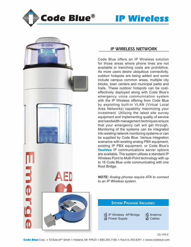
SyStem Package IncludeS:
CS-149-C
IP WIReleSS netWORk
Code Blue offers an IP Wireless solution for those areas where phone lines are not available or trenching costs are prohibitive. As more users desire ubiquitous connectivity, outdoor hotspots are being added and some include campus common areas, multiple city blocks, town centers and municipal parks and trails. These outdoor hotspots can be cost-effectively deployed along with Code Blue’s emergency voice communication system with the IP Wireless offering from Code Blue by exploiting built-in VLAN (Virtual Local Area Networks) capability maximizing your investment. Utilizing the latest site survey equipment and implementing quality of service and bandwidth management techniques ensure that your emergency call will get through. Monitoring of the systems can be integrated into existing network monitoring systems or can be supplied by Code Blue. Various integration scenarios with existing analog PBX equipment, existing IP PBX equipment, or Code Blue’s ToolVox IP communications server options are available. The system utilizes a standard IP Wireless Point to Multi-Point technology with up to 16 Code Blue units communicating with one Root Bridge.
NOTE: Analog phones require ATA to connect to an IP Wireless system.
IP Wireless AP/Bridge Power Supply
Antenna Cables

BLUE ALERT Mass Notification System
Description
Software Features
System Requirements
Code Blue Corporation’s BLUE ALERT Mass Notification System combines
state of the art amplifiers, speaker arrays and sophisticated software control
to provide industry leading and NFPA 72, 2010 Chapter 24 compliant mass
notification capabilities to your college or corporate campus.
Protect your corporate, medical or higher education campus, military base or
community from criminal threats, acts of terror, inclement weather and
natural disasters by ensuring your announcements are delivered.
BLUE ALERT allows flexibility in the delivery of announcements by providing
text to speech, live broadcast and pre-recorded messages/warning tones
options as well as announcement repeat and scheduling features.
Integrate existing IP based systems easily with our robust API or utilize our
analog products to integrate non IP based systems. Either way Code Blue
Corporation can provide a complete turnkey Mass Notification System or
integrate with your existing emergency notification systems.
Live Broadcast
Text to Speech
Pre-Recorded Messages
Warning Tones
Scheduled Announcements Options
Repeating Announcements Options
All Page
Group Page
Individual Page
Dial Extension/Phone Number for Mass Notification
Client/Server Based Architecture
Web Based Administration
GUI Client Software
o Compatible with Windows XP/Vista/7
API Integration
ToolVox IP Communications Server licensed with BLUE ALERT
Units equipped with IA4100/IA7700 phones
Optional PAS units

Stand Alone System
Integrated with
Customer PBX
BLUE ALERT System Diagrams

Parameters
Load Resistance
Max Output Power
Output Power
Sensitivity
Gain
Mute Gain
Distortion
Freq. Response
Noise Floor
Maximum Current
Damping Factor
Power Bandwidth
Small Signal Bandwidth
Signal to Noise
Features
Speaker
Impedance
Frequency Range
Power Capacity
Symbols Test Condition/ Comment Min Typ Max Unit
RL
2.5 - - Ohms
Pmax f=20Hz-20KHz (1% THD) - 500 - W
Po f=20Hz-20kHz (0.1% THD) - 400 - W
Vsen Input Signal to 400W - 3.5 - Vrms
A
20.5 21 21.5 dB
Amute Disable Pin pulled low. -45 - - dB
THD+N 10Hz< f <20kHz, 100mW< Pout < Po - 0.03 0.05 %
f 20Hz-20kHz - +/-0.5 - dB
VNF Input Shorted, A-weighted - 70 80 uV
Imax
23 26 29 A
DF RL = 4 ohms @ 100 Hz - 375 - Ohms
BWpw Output Power: Pmax - 60k - Hz
BWsm Output Power: 1Watt - 90k - Hz
SNR
108.5 - - dB
●Proprietary One-Cycle Sound
TM Control with Output
Feedback
● 117 dBA dynamic Range
● THD+N < 0.05%, 0.1W – Rated Power
● Full range 20 to 20kHz Bandwidth
● System Efficiency > 85%
● Damping Factor > 375 @ 100Hz 4 Ohms
● DC offset < 25mV
● Remote Disable
● Silent Turn-On
● Full Protection: - Over Current Protection to Speaker Short - Over Current Protection Short to Chassis Ground - Over Temperature Protection - Power On Self Test (POST) - Power Supply Under Voltage Lockout
● Monitor Outputs: - Output Current Monitor - Temperature Monitor - Protect, Clip and Signal Present Indicators
Internal and remote volume adjustment
5.3 Ohms
450 Hz to 7000 Hz
420 Watts Continuous Program
BLUE ALERT PAS 1 Specifications (Used on all CB1 & CB5 units)

Parameters
Load Resistance
Max Output Power
Output Power
Max Bridged
Output Power
Sensitivity
Gain
Distortion
Freq. Response
Noise Floor
Maximum Current
Peak Current
Damping Factor
Power Bandwidth
Small Signal
Bandwidth
Signal to Noise
Features
Speaker
Impedance
Frequency Range
Power Capacity
Symbols Test Condition/ Comment Min Typ Max Unit
RL
2.5 - - Ohms
Pmax f=20Hz-20KHz (1% THD)
160 - W
Po f=20Hz-20kHz (0.1% THD) - 150 - W
Pmaxb 1% THD
500
W
Vsen Input Signal to Po - 3.5 - Vrms
A
21 22 23 dB
THD+N 10Hz< f <20kHz, - 0.03 0.05 %
100mW< Pout < Po
f 20Hz-20kHz - +/- 0.5 - dB
VNF Input Shorted, A-weighted - 25 35 uV
Imax
18 20 25 A
Ipk
27
A
DF RL = 4 ohms @ 100 Hz - 375 - Ohms
BWpw Output Power: Pmax - 60k - Hz
BWsm Output Power: 1Watt - 90k - Hz
SNR
117 - - dB
● Patented One-Cycle SoundTM Control ● 2x 150W Switching Amplifiers ● Bridgeable to 500W (4Ohms, 1% THD+N) ● Synchronized Switching Frequencies ● Output Feedback ● 117 dBA dynamic Range ● THD+N < 0.05%, 0.1W to 150W per channel ● Full range 20 to 20kHz Bandwidth ● Efficiency: Amp > 95% ● Damping Factor > 375 @ 100Hz 4 Ohms ● DC offset < 25mV ● Remote Disable ● Silent Turn-On ● Full Protection:
- Over Current Speaker Short - Over Current Short to Chassis Ground - Over Temperature Protection - Power Supply Under Voltage Lockout
● Monitor Outputs: - Output Current Monitor - Temperature Monitor - Protect and Power On
Internal and remote volume adjustment
8 Ohms
450 Hz to 7000 Hz
70 Watts Continuous Program
BLUE ALERT PAS 2-e Specifications

Parameters
Load Resistance
Max Output Power
Output Power
Max Bridged
Output Power
Sensitivity
Gain
Distortion
Freq. Response
Noise Floor
Maximum Current
Peak Current
Damping Factor
Power Bandwidth
Small Signal
Bandwidth
Signal to Noise
Features
Speaker
Impedance
Frequency Range
Power Capacity
Symbols Test Condition/ Comment Min Typ Max Unit
RL
2.5 - - Ohms
Pmax f=20Hz-20KHz (1% THD)
160 - W
Po f=20Hz-20kHz (0.1% THD) - 150 - W
Pmaxb 1% THD
500
W
Vsen Input Signal to Po - 3.5 - Vrms
A
21 22 23 dB
THD+N 10Hz< f <20kHz, - 0.03 0.05 %
100mW< Pout < Po
f 20Hz-20kHz - +/- 0.5 - dB
VNF Input Shorted, A-weighted - 25 35 uV
Imax
18 20 25 A
Ipk
27
A
DF RL = 4 ohms @ 100 Hz - 375 - Ohms
BWpw Output Power: Pmax - 60k - Hz
BWsm Output Power: 1Watt - 90k - Hz
SNR
117 - - dB
● IP Controller ● FXS Analog Controller ● No Controller. Controlled by a local Code Blue IA4100/IA5000 ●Patented One-Cycle SoundTM Control ● 2x 150W Switching Amplifiers ● Bridgeable to 500W (4Ohms, 1% THD+N) ● Synchronized Switching Frequencies ● Output Feedback ● 117 dBA dynamic Range ● THD+N < 0.05%, 0.1W to 150W per channel ● Full range 20 to 20kHz Bandwidth ● Efficiency: Amp > 95% ● Damping Factor > 375 @ 100Hz 4 Ohms ● DC offset < 25mV ● Remote Disable ● Silent Turn-On ● Full Protection:
- Over Current Chassis/Speaker - Over Temperature Protection - Power Supply Under Voltage Lockout
● Monitor Outputs: - Output Current Monitor - Temperature Monitor - Protect and Power On
Internal and remote volume adjustment
2.7 Ohms
450 Hz to 7000 Hz
210 Watts Continuous Program
BLUE ALERT PAS WM180(A,IP,NC) Specifications