code: 80992E - 07-2021 - ENGLISH
52
GFX4-IR PROFINET USER MANUAL code: 80992E - 07-2021 - ENGLISH
Transcript of code: 80992E - 07-2021 - ENGLISH

GFX4-IR PROFINET
USER MANUAL
code: 80992E - 07-2021 - ENGLISH

2 80992E_MSW_PROFINET_GFX4-IR_07-2021_ENG

380992E_MSW_PROFINET_GFX4-IR_07-2021_ENG
INDEX
1 • INTRODUCTION ���������������������������������������������������������������������������������������������������������������������������������������������������������4
2 • MAIN CHARACTERISTICS ����������������������������������������������������������������������������������������������������������������������������������������5
3 • CONNECTING HOST DEVICES ��������������������������������������������������������������������������������������������������������������������������������73�1� Possible connections ���������������������������������������������������������������������������������������������������������������������������������������������������������������7
3.3.1. Connection diagram 1 (4 zones) : .............................................................................................................................73.3.2. Connection diagram 2 ( 8 zones): .............................................................................................................................73.3.3. Connection diagram 3 ( 12 zones) : ..........................................................................................................................83.3.4. Connection diagram 4 ( 16 zones ) : .........................................................................................................................9
3�2� Description of data exchange �������������������������������������������������������������������������������������������������������������������������������������������������10
4 • USING STEP 7����������������������������������������������������������������������������������������������������������������������������������������������������������114.1. From gsdml description file to data exchange ������������������������������������������������������������������������������������������������������������������������11
4.4.1. Configuration for Connection 1 (4 zones) : ...............................................................................................................154.4.2. ConConfiguration for Connection 2 (8 zones) : .......................................................................................................184.4.3. Configuration for Connection 3 (12 zones) : .............................................................................................................184.4.4. Configuration for Connection 4 ( 16 zones ) : ..........................................................................................................194.4.5. Modbus virtual slot 5 ................................................................................................................................................19
5 • USING TIAPORTAL ��������������������������������������������������������������������������������������������������������������������������������������������������235.1. From descriptive GSDML file to data exchange ���������������������������������������������������������������������������������������������������������������������235�2� Setting Names and IP Addresses �������������������������������������������������������������������������������������������������������������������������������������������255.3. Configuration for Connection Diagram 1 ( 4 zones ): �������������������������������������������������������������������������������������������������������������265.4. Default process data ��������������������������������������������������������������������������������������������������������������������������������������������������������������275.5. Configuration for Connection Diagram 2 ( 8 zones ): �������������������������������������������������������������������������������������������������������������295.6. Configuration for Connection Diagram 3 ( 12 zones ): �����������������������������������������������������������������������������������������������������������295.7. Configuration for Connection Diagram 4 ( 16 zones ): �����������������������������������������������������������������������������������������������������������295.8. Modbus Virtual slot 5: �������������������������������������������������������������������������������������������������������������������������������������������������������������30
6 • DIAGNOSTICS USING STEP 7 ��������������������������������������������������������������������������������������������������������������������������������316�1� Incorrect setting of dip-switch 7 ����������������������������������������������������������������������������������������������������������������������������������������������316.2. Communication fault on Modbus serial ����������������������������������������������������������������������������������������������������������������������������������31
7 • DIAGNOSTICS USING THE TIA PORTAL ��������������������������������������������������������������������������������������������������������������337.1. Communication fault on modbus serial ����������������������������������������������������������������������������������������������������������������������������������33
8 • Modbus RTU connection diagram �������������������������������������������������������������������������������������������������������������������������34
9 • GEFRAN SW LIBRARIES FOR SIEMENS S7 ���������������������������������������������������������������������������������������������������������359�1� Installation ������������������������������������������������������������������������������������������������������������������������������������������������������������������������������359.2. Functions ��������������������������������������������������������������������������������������������������������������������������������������������������������������������������������37
9.9.1. UDT6 ........................................................................................................................................................................379.9.2. FC4 “FC_PD_GFX4_IR” (FUNCTION CALL) ” ........................................................................................................389.9.3. UDT5 ........................................................................................................................................................................419.9.4. FC3 “FC_CFG_GFX4-IR” (FUNCTION CALL) ” .......................................................................................................41
9.3. Function blocks ����������������������������������������������������������������������������������������������������������������������������������������������������������������������439.9.1. FB1 “FB_OP_GFX4_IR” (FUNCTION BLOCK) .......................................................................................................439.9.2. FB15 “FB_RCP_GFX4_IR” (FUNCTION BLOCK) ...................................................................................................449.9.3. UDT7 ........................................................................................................................................................................459.9.4. DB20.........................................................................................................................................................................48

4 80992E_MSW_PROFINET_GFX4-IR_07-2021_ENG
1 • INTRODUCTION
The RTE (Real Time Ethernet) card is a device that connects slaves for data transmission and reception withthe Profinet protocol� The connection diagram is shown below�
Figure 1
We have: ● A Profinet-controller master connected to a Profinet-IO device (Gefran RTE Profinet Bridge) via the Profinet protocol (green) ● A Modbus RTU master running on the RTE card (Gefran Profinet Bridge) connected via serial line to a Modbus slave RTU

580992E_MSW_PROFINET_GFX4-IR_07-2021_ENG
2 • MAIN CHARACTERISTICS ● Profinet-IO module ↔ Modbus RTU ● Two Ethernet RJ45 ports: Eth 0 and Eth 1 ● Internal switch ● Baud rate 100Mbits ● Auto_Negotiation, Auto_Polarity, Auto_Crossover ● Internal installation ● Data transport layer Ethernet II , IEEE 802.3 ● RTC – Real time Cyclic Protocol- Class 1 & Class 2 (unsynchronised) ● RTA – Real time Acyclic Protocol ● Device address via DCP– Discovery and Configuration Protocol ( No DHCP ) ● CL-RPC – Connectionless Remote Procedure Call ● LLDP – Link Layer Discovery Protocol ● No fast star-tup ● 32 input words (16 bits per word ) for each GFX4-IR ● 32 output words (16 bits per word ) for each GFX4-IR ● Minimum device interval for Profinet cyclic data: 8ms ● Supports GFX4 standard address mode (dip-switch 7 off)
Figure 2
● Minimum cycle time on serial: 50ms for 16 contiguous words using GFX4-IR custom map function
dip switch for configuration software

6 80992E_MSW_PROFINET_GFX4-IR_07-2021_ENG
● DCP signal LED on front panel
Figure 3
Serial communication time constraints in Modbus RTU
The following time constraints must be complied with in order to allow correct serial data exchange with the device:
Reading Word/Register parameters: Reading N consecutive parameters, with N from 1 to 16, requires a time of almost50 ms. In this case the following read and write Modbus command, to the same node, must be sent after this intervaltime�
Writing Word/Register parameters: Writing N consecutive parameters, with N ranging from 1 to 16, if all values (maximum16) on the device are updated, will take a time of:50ms + N x 80ms(*) with N from 1 to 16.
The times reported refer to the case in which the Baudrate of the serial line (parameter bAu Modbus address 45) is19200�
(*) If STATUS_W parameters (Modbus address 305) are included in the write request and their value is different from the one currently present in the slave, the time required to write each one will be 240ms (instead of 80ms).

780992E_MSW_PROFINET_GFX4-IR_07-2021_ENG
3 • CONNECTING HOST DEVICES
Data is exchanged in the GFX4-IR device by encapsulating Modbus data in Profinet packets. The serial port must be configured as follows:
● Serial link speed: 19200 baud ● No parity ● Data 8 bits ● Modbus node addresses MUST BE between 1 and 4 in sequence ● The GFX4-IR with Profinet card MUST have address 1
3�1� Possible connections
The following pages show possible combinations for connection and address of GFX4-IR modules. Connection combinations other than those shown below WILL NOT allow Profinet communication with a Controller!
3�3�1� Connection diagram 1 (4 zones) : 1 GFX4-IR with Modbus node address = 1 and dip switch 7 Off.
Figure 4
3�3�2� Connection diagram 2 ( 8 zones): 2 GFX4-IRs with Modbus node addresses = 1 and 2 and dip switch 7 Off.
Figure 5

8 80992E_MSW_PROFINET_GFX4-IR_07-2021_ENG
3�3�3� Connection diagram 3 ( 12 zones) : 3 GFX4-IRs with Modbus node addresses = 1 2 and 3 and dip switch 7 Off.
Figure 6

980992E_MSW_PROFINET_GFX4-IR_07-2021_ENG
3�3�4� Connection diagram 4 ( 16 zones ) : 4 GFX4-IRs with Modbus node addresses = 1,2,3 and 4 dip switch 7 Off.
Figure 7

10 80992E_MSW_PROFINET_GFX4-IR_07-2021_ENG
3�2� Description of data exchange
The Profinet-IO module on the GFX4-IR device supports the following data types
● Parameter data ● Cyclic data ● Acyclic data
This data is characterised by device description file GSDML .
Data flows must be interpreted by the application that produces/consumes the data transmitted/received by thedevice�
The Gefran Profinet-IO card acts like a bridge between Modbus serial and Profinet Ethernet. Data flows as follows:
● from Profinet-controller master to Profinet-IO slave and vice versa via acyclic mailboxes (acyclic and parameter data) ● or via cyclic data for fast IO data.
Use a configuration tool to define which slave data are exchanged via fast cyclic data.

1180992E_MSW_PROFINET_GFX4-IR_07-2021_ENG
4 • USING STEP 7
4�1� From gsdml description file to data exchange
To activate data exchange, download the GSDML product description file (GSDML-V2.2-GEFRANGFX4IR-
20120102.xml) from www.gefran.com and install it in the programming environment.
After this, you can see the Controllers → Geflex folders with the GFX4-IR Standard Mode module (Figure 8)
Figure 8
You can now connect to the network (2) by dragging the device (1) as shown in Figure 9
Figure 9

12 80992E_MSW_PROFINET_GFX4-IR_07-2021_ENG
If you need to set a device name/ip address, do it with the System Manager tool using the PLC → Ethernet → Edit Ethernet Node menus (Figure 10)
Figure 10
In the Edit Ethernet Node window, click the Browse button (Figure 11) to search for nodes accessible online.This will take a few seconds
Figure 11After a few seconds, the Browse Network window appears, summarising the current settings of the nodes connectedto the network.
The example shows a network consisting of two nodes: ● a controller ● a GFX4-IR device

1380992E_MSW_PROFINET_GFX4-IR_07-2021_ENG
To change the settings (Figure 12) of the GFX4-IR, select the line with Device type = GEFLEX (1) and confirmwith OK (2)
Figure 12
14 80992E_MSW_PROFINET_GFX4-IR_07-2021_ENG
The next window opens (Figure 13)for setting the Device name / ip address. DHCP protocol is not supported.
Figure 13

1580992E_MSW_PROFINET_GFX4-IR_07-2021_ENG
Let’s see how to insert a device in the configuration tool (HW-config window).
4�4�1� Configuration for Connection 1 (4 zones) :
Figure 14
Figure 14 shows the GFX4-IR device in slot 1, controlling 4 zones.
There is also a generic Modbus channel in slot 5 (see description of Modbus channel).If you click the module, slot 1 is as shown in Figure 15:
Figure 15
You can check/change the parameters of the process I/O variables (Figure 16)
Figure 16

16 80992E_MSW_PROFINET_GFX4-IR_07-2021_ENG
There are 32 input variables in two blocks ● Input Parameter Record 1 ( 16 words ) ● Input Parameter Record 2 ( 16 words )
In the Value column, you can change the parameter value if necessary (Figure 17)
Figure 17

1780992E_MSW_PROFINET_GFX4-IR_07-2021_ENG
In the Value column, you can change the parameter value if necessary: ● Output Parameter Record 1 ● Output Parameter Record 2
In the Value column, you can change the output variables if necessary (Figure 18)
Figure 18

18 80992E_MSW_PROFINET_GFX4-IR_07-2021_ENG
4�4�2� ConConfiguration for Connection 2 (8 zones) : Select the GFX4-IR Standard Mode module with the configuration tool and drag it to slot 2. The Modbus moduleis in slot 5 (Figure 19)
Figure 19
As described above, you can parameterise input and output data in the parameters window of each module.
4�4�3� Configuration for Connection 3 (12 zones) :Select the GFX4-IR Standard Mode module with the configuration tool, drag it to slot 2 and then to slot 3. TheModbus module is in slot 5 (Figure 20).
Figure 20
As described above, you can parameterise input and output data in the parameters window of each module.

1980992E_MSW_PROFINET_GFX4-IR_07-2021_ENG
4�4�4� Configuration for Connection 4 ( 16 zones ) : Select the GFX4-IR Standard Mode module with the configuration tool, drag it to slot 2 , 3 and then to slot 4.The Modbus module is in slot 5 (Figure 21).
Figure 21
As described above, you can parameterise input and output data in the parameters window of each module.
4�4�5� Modbus virtual slot 5 Slot 5 (Figure 22) is a virtual device that encapsulates a Modbus control in cyclic Profinet data.
Figure 22
20 80992E_MSW_PROFINET_GFX4-IR_07-2021_ENG
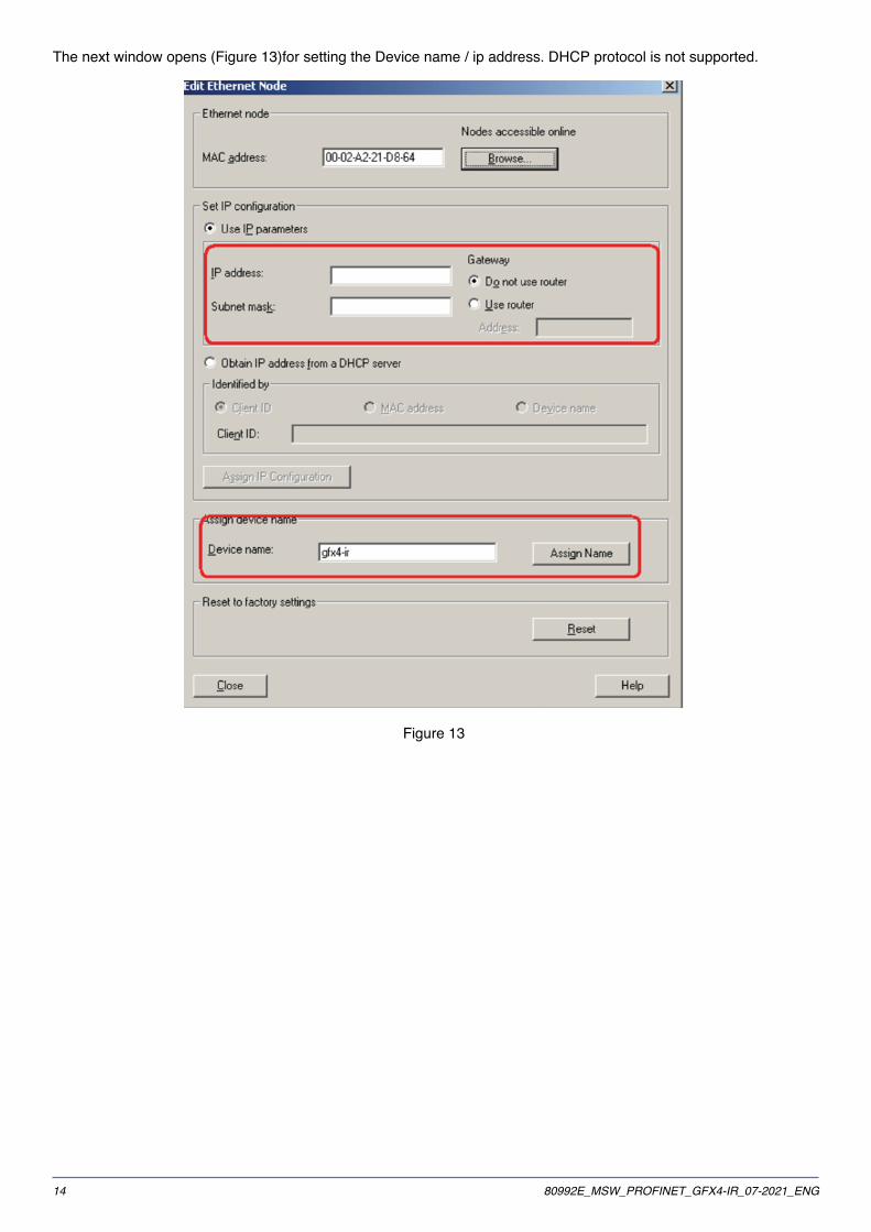
You can configure a few communication aspects in the module parameters.
● Fault Mode (Fig.16) : if Profinet communication fails, you may set the modules as follows
Ѵ Take no action Ѵ Device to Software Off mode Ѵ Device to manual mode Ѵ Set SP2 as Setpoint
Figure 23
● Modbus Read Mode (Figure 24) :
Ѵ Normal Modbus read: all 32 input words are updated in read (Input parameter record 1 and Input parameter record 2)
Ѵ Half Modbus read: if the read variables needed by the application are equal to a maximum of 16 words, only the parameter record 1 inputs are updated
Figure 24
Modbus slot 5 has a dimension of 8 bytes in write and 8 bytes in read. With this channel you can read or write anyvariable on the Modbus map of the GFX4-IR modules connected to the network.
Modbus channel, slot 5 output, size 8 bytes
MODBUS OUTPUT CHANNELBYTE1BYTE2 BYTE 3 BYTE 4 BYTE 5 BYTE 6 BYTE 7 BYTE 8
REQUEST TRIGGERWORD
MODBUS ADDRESS FUNCTION CODE DATA 1 DATA 2 DATA 3 DATA 4

2180992E_MSW_PROFINET_GFX4-IR_07-2021_ENG
Canale modbus , slot 5 input , size 8bytes
MODBUS INPUT CHANNELBYTE1BYTE2 BYTE 3 BYTE 4 BYTE 5 BYTE 6 BYTE 7 BYTE 8
REQUEST TRIGGERWORD
MODBUS ADDRESS FUNCTION CODE DATA 1 DATA 2 DATA 3 DATA 4
DESCRIPTIONBYTE OFFSET PARAMETER DESCRIPTION
0 REQUEST/RESPONSETRIGGER WORD
TRIGGER WORD REQUEST: MUST BE INCREASED BY 1FOR EACH NEW REQUEST.THE ANSWER IS VALID WHEN
THE TRIGGER WORD RESPONSE IS EQUAL TO THETRIGGER WORD REQUEST
2 SLAVE ADDRESS MODBUS ADDRESS OF GFX4-IR3 FUNCTION CODE FUNCTION CODE BIT/WORD READ/WRITE4 DATA 1 DEPENDS ON FUNCTION CODE5 DATA 2 DEPENDS ON FUNCTION CODE6 DATA 3 DEPENDS ON FUNCTION CODE7 DATA 4 DEPENDS ON FUNCTION CODE
Reading a bit (1,2)
REQUEST
TRG SLAVEADDRESS
FUNCTIONCODE
ADDRESS BITBYTE +
MEANING
ADDRESS BITBYTE -
MEANING
NUMBER BITBYTE +
MEANING
NUMBER BITBYTE -
MEANINGREQUESTTRIGGER
WORD
SLAVEADDRESS
1 or 2 ADDRESS OFBIT TO READ
ADDRESS OFBIT TO READ
NUMBER OFBITS TO READ.
(MUST BE 0)
NUMBER OFBITS TO READ
RESPONSE
TRG SLAVEADDRESS
FUNCTION CODE BYTES COUNT BIT BIT #
RESPONSETRIGGER
WORD
SLAVEADDRESS
CONFIRMCODE
NUMBER OFBYTE
(1 OR 2)
VALUE OF BITS(1÷8)
VALUE OF BITS(9÷16)
DUMMY
Reading a word (3,4)
REQUEST
TRG ADD SLAVE
FUNCTION CODE
ADDRESSWORD +
MEANING
ADDRESSWORD -
MEANING
NUMBERWORD +
MEANING
NUMBERWORD -
MEANINGREQUESTTRIGGER
WORD
SLAVEADDRESS
3 O 4 ADDRESS OFWORD TO
READ
ADDRESS OFWORD TO
READ
0 1
RESPONSE
TRG ADD SLAVE
FUNCTION CODE BYTES COUNT DATA WORD +
MEANINGDATA WORD –
MEANING #
RESPONSETRIGGER
WORD
SLAVEADDRESS
CODICE FUNZIONE
NUMBER OFBYTES READ
VALUE VALUE DUMMY

22 80992E_MSW_PROFINET_GFX4-IR_07-2021_ENG
Scrittura bit (5)
REQUEST
TRG ADD SLAVE
FUNCTION CODE
ADDRESS +MEANING
ADDRESS -MEANING BIT #
REQUESTTRIGGER
WORD
SLAVEADDRESS
5 ADDRESS OFBIT TO WRITE
ADDRESS OFBIT TO WRITE
VALUE OF BIT00 = OFF o
FFHEX = ON)
0
RESPONSE
TRG ADD SLAVE
FUNCTION CODE
ADDRESS +MEANING
ADDRESS -MEANING BIT 00
RESPONSETRIGGER
WORD
SLAVEADDRESS
CONFIRMCODE
ADDRESS OFBIT WRITTEN
ADDRESS OFBIT WRITTEN
VALUE OF BIT00 = OFF o
FFHEX = ON)
0
Writing a word (6)
REQUEST
TRG SLAVEADDRESS
FUNCTION CODE
ADDRESS +MEANING
ADDRESS -MEANING
DATA +MEANING
DATA - MEANING
REQUESTTRIGGER
WORD
SLAVEADDRESS
6 ADDRESSOF WORD TO
WRITE
ADDRESSOF WORD TO
WRITE
VALUE OFWORD TO
WRITE
VALUE OFWORD TO
WRITE
RISPOSTA
TRG SLAVEADDRESS
FUNCTION CODE
ADDRESS + MEANING
ADDRESS -MEANING
DATA + MEANING
DATA - MEANING
RESPONSETRIGGER
WORD
SLAVEADDRESS
CONFIRMCODE
ADDRESS OFWORD
WRITTEN
ADDRESS OFWORD
WRITTEN
VALUE OFWORD
WRITTEN
VALUE OFWORD
WRITTEN
In case of error, 80 hex plus the value of the request function code is returned in the response function code
RESPONSE
TRG SLAVEADDRESS
FUNCTIONCODE
ERRORCODE # # #
RESPONSETRIGGER
WORD
CONFIRMSLAVE
ADDRESS
REQUESTFUNCTION
CODE +80HEX
ERROR CODE DUMMY DUMMY DUMMY
Error Code
1 2 3 9 10ILLEGAL FC ILLEGAL DATA
ADDRESSILLEGAL DATA ILLEGAL NUMBER OF
DATADATA IS READ
ONLY

2380992E_MSW_PROFINET_GFX4-IR_07-2021_ENG
5 • USING TIAPORTAL
5�1� From descriptive GSDML file to data exchange
In order to activate the data exchange, you must obtain the GSDML file describing the product (GSDML-V2.2-GEFRAN-GFX4IR-20120102.xml), downloadable from www.gefran.com, and install it in the programming environment.To install the device, select “Options/Manage general station description files (GSD)” (Figure 25).
Figure 25
Select the desired item in the dialogue box that appears and click on “Install” (Figure 26).
Figure 26
After doing this, you will see the selected device in the catalogue “Other field devices/Controllers/Gefran Spa/GEFLEX/GEFRAN GFX4IR” (Figure 27):
Figure 27

24 80992E_MSW_PROFINET_GFX4-IR_07-2021_ENG
Once you have added and configured your master plc, you may insert your slave device, dragging it as shown in Figure 28
Figure 28
You must now connect the slave (GFX4IR) to the Master’s ProfiNET network, joining the two green squares with the mouse as shown in Figure 29.
Figure 29

2580992E_MSW_PROFINET_GFX4-IR_07-2021_ENG
5�2� Setting Names and IP Addresses
Follow this procedure if it is necessary to set a different device name or IP address.Establish a point-to-point connection with the desired device, for example first with the master plc and then with the GFX4IR slave. Double click on the project tree, at the item “Update accessible devices” (Figure 30 and Figure 31)
Figure 30 Figure 31
Once we have identified the device, double click on “Online & diagnostics“ to access the necessary commands in the corresponding “Functions” menus (Figure 32 and Figure 33).
Figure 32 Figure 33
You may change the IP address under the item “Functions/Assign IP address” (Figure 34).
Figure 34
You may change the name under the item “Functions/Assign PROFINET device name” (Figure 35).
Figure 35

26 80992E_MSW_PROFINET_GFX4-IR_07-2021_ENG
5�3� Configuration for Connection Diagram 1 ( 4 zones ):
Figure 36 shows the GFX4-IR device in slot 1 controlling 4 zones.There is also a generic modbus channel in slot 5 (refer to the description of the modbus channel).
Figure 36
The same information may be accessed via a similar representation (empty slots not shown) in the project tree on the left (Figure 37).
Figure 37
Double click on “GFX4-IR Standard Mode_1” in the “Device overview” in Figure 12 to go to the “Properties” window, where the item “Module parameters” shows a map of the device's memory (Figure 38).
Figure 38
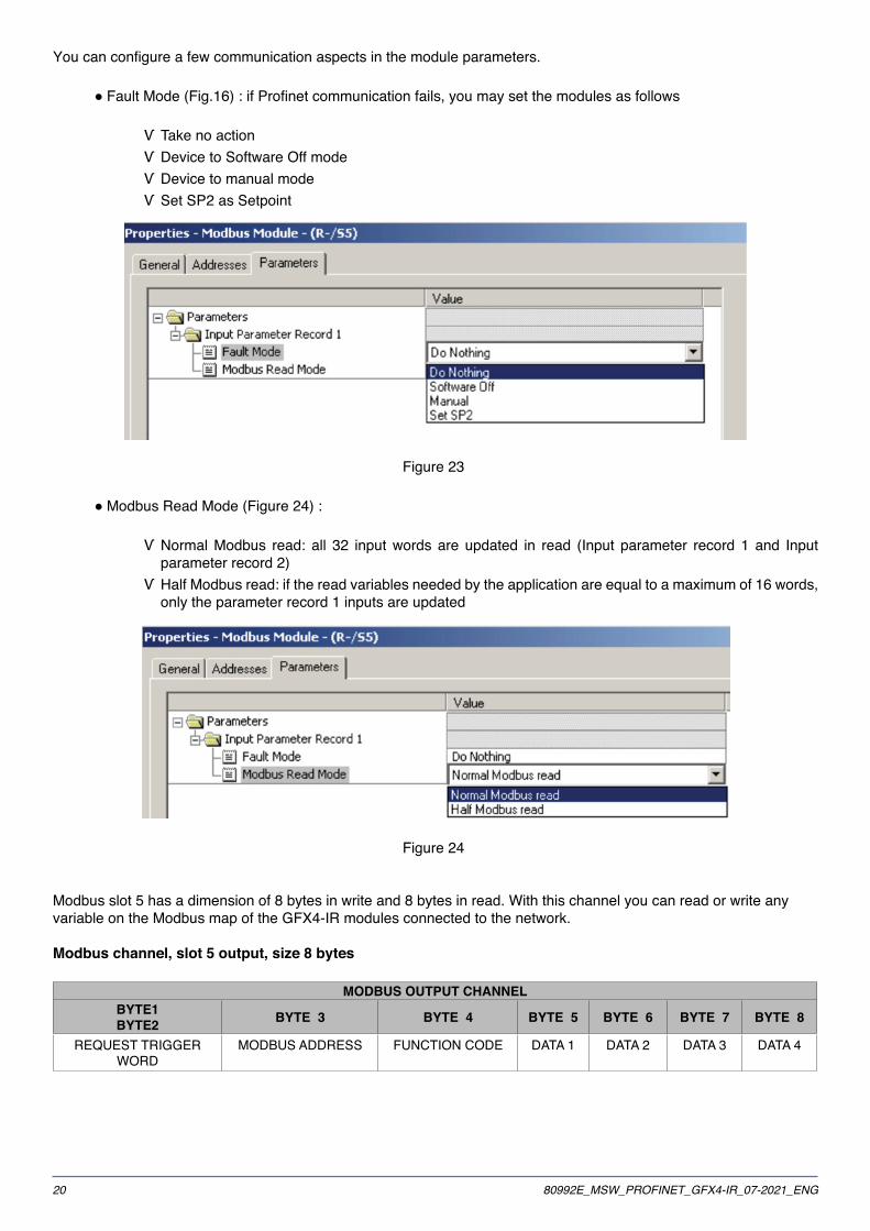
The same information may be accessed in a dialogue box, using the project tree shown in Figure 13. Select “GFX4-IR Standard Mode_1”, click with the right mouse button and select the item “Properties” in the context-specific menu that appears.The following default variables are available:
● 32 input variables in two blocks Ѵ Input Parameter Record 1 ( 16 words ) Ѵ Input Parameter Record 2 ( 16 words )
● 32 output variables in two blocks Ѵ Output Parameter Record 1 ( 16 words ) Ѵ Output Parameter Record 2 ( 16 words )
To modify them, simply click on the item in question and select the desired variable from among those proposed.
2780992E_MSW_PROFINET_GFX4-IR_07-2021_ENG
Figure 39
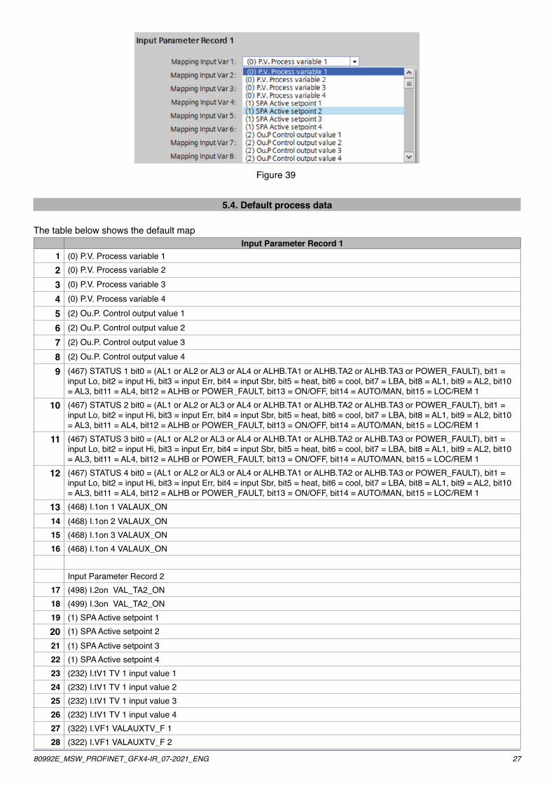
5�4� Default process data
The table below shows the default mapInput Parameter Record 1
1 (0) P.V. Process variable 12 (0) P.V. Process variable 2
3 (0) P.V. Process variable 3
4 (0) P.V. Process variable 4
5 (2) Ou.P. Control output value 1
6 (2) Ou.P. Control output value 2
7 (2) Ou.P. Control output value 3
8 (2) Ou.P. Control output value 4
9 (467) STATUS 1 bit0 = (AL1 or AL2 or AL3 or AL4 or ALHB.TA1 or ALHB.TA2 or ALHB.TA3 or POWER_FAULT), bit1 = input Lo, bit2 = input Hi, bit3 = input Err, bit4 = input Sbr, bit5 = heat, bit6 = cool, bit7 = LBA, bit8 = AL1, bit9 = AL2, bit10 = AL3, bit11 = AL4, bit12 = ALHB or POWER_FAULT, bit13 = ON/OFF, bit14 = AUTO/MAN, bit15 = LOC/REM 1
10 (467) STATUS 2 bit0 = (AL1 or AL2 or AL3 or AL4 or ALHB.TA1 or ALHB.TA2 or ALHB.TA3 or POWER_FAULT), bit1 = input Lo, bit2 = input Hi, bit3 = input Err, bit4 = input Sbr, bit5 = heat, bit6 = cool, bit7 = LBA, bit8 = AL1, bit9 = AL2, bit10 = AL3, bit11 = AL4, bit12 = ALHB or POWER_FAULT, bit13 = ON/OFF, bit14 = AUTO/MAN, bit15 = LOC/REM 1
11 (467) STATUS 3 bit0 = (AL1 or AL2 or AL3 or AL4 or ALHB.TA1 or ALHB.TA2 or ALHB.TA3 or POWER_FAULT), bit1 = input Lo, bit2 = input Hi, bit3 = input Err, bit4 = input Sbr, bit5 = heat, bit6 = cool, bit7 = LBA, bit8 = AL1, bit9 = AL2, bit10 = AL3, bit11 = AL4, bit12 = ALHB or POWER_FAULT, bit13 = ON/OFF, bit14 = AUTO/MAN, bit15 = LOC/REM 1
12 (467) STATUS 4 bit0 = (AL1 or AL2 or AL3 or AL4 or ALHB.TA1 or ALHB.TA2 or ALHB.TA3 or POWER_FAULT), bit1 = input Lo, bit2 = input Hi, bit3 = input Err, bit4 = input Sbr, bit5 = heat, bit6 = cool, bit7 = LBA, bit8 = AL1, bit9 = AL2, bit10 = AL3, bit11 = AL4, bit12 = ALHB or POWER_FAULT, bit13 = ON/OFF, bit14 = AUTO/MAN, bit15 = LOC/REM 1
13 (468) I.1on 1 VALAUX_ON14 (468) I.1on 2 VALAUX_ON15 (468) I.1on 3 VALAUX_ON16 (468) I.1on 4 VALAUX_ON
Input Parameter Record 217 (498) I.2on VAL_TA2_ON18 (499) I.3on VAL_TA2_ON19 (1) SPA Active setpoint 120 (1) SPA Active setpoint 221 (1) SPA Active setpoint 322 (1) SPA Active setpoint 423 (232) I.tV1 TV 1 input value 124 (232) I.tV1 TV 1 input value 225 (232) I.tV1 TV 1 input value 326 (232) I.tV1 TV 1 input value 427 (322) I.VF1 VALAUXTV_F 128 (322) I.VF1 VALAUXTV_F 2

28 80992E_MSW_PROFINET_GFX4-IR_07-2021_ENG
Input Parameter Record 129 (322) I.VF1 VALAUXTV_F 330 (322) I.VF1 VALAUXTV_F 431 (317) - Digital input status INPUT_DIG32 (140) diG. Digital input function
Output Parameter Record 11 (16) _SP Local setpoint 12 (16) _SP Local setpoint 23 (16) _SP Local setpoint 34 (16) _SP Local setpoint 45 (252) - MAN_POWER: Control output value in manual mode 16 (252) - MAN_POWER: Control output value in manual mode 27 (252) - MAN_POWER: Control output value in manual mode 38 (252) - MAN_POWER: Control output value in manual mode 49 (305) STATUSW 1 bit1= SP1/SP2, bit2= start/stop selftuning,bit3 = ON/OFF, bit4 = AUTO/MAN, bit5= start/stop
autotuning, bit6 = LOC/REM10 (305) STATUSW 2 bit1= SP1/SP2, bit2= start/stop selftuning,bit3 = ON/OFF, bit4 = AUTO/MAN, bit5= start/stop
autotuning, bit6 = LOC/REM11 (305) STATUSW 3 bit1= SP1/SP2, bit2= start/stop selftuning,bit3 = ON/OFF, bit4 = AUTO/MAN, bit5= start/stop
autotuning, bit6 = LOC/REM12 (305) STATUSW 4 bit1= SP1/SP2, bit2= start/stop selftuning,bit3 = ON/OFF, bit4 = AUTO/MAN, bit5= start/stop
autotuning, bit6 = LOC/REM13 (12) AL.1 Alarm point 1 ( if relative ) [if relative and symmetrical]14 (12) AL.1 Alarm point 2 ( if relative ) [if relative and symmetrical]15 (12) AL.1 Alarm point 3 ( if relative ) [if relative and symmetrical]16 (12) AL.1 Alarm point 4 ( if relative ) [if relative and symmetrical]
Output Parameter Record 217 (13) AL.2 Alarm point 1 ( if relative ) [if relative and symmetrical]18 (13) AL.2 Alarm point 2 ( if relative ) [if relative and symmetrical]19 (13) AL.2 Alarm point 3 ( if relative ) [if relative and symmetrical]20 (13) AL.2 Alarm point 4 ( if relative ) [if relative and symmetrical]21 (14) AL.3 Alarm point 1 ( if relative ) [if relative and symmetrical]22 (14) AL.3 Alarm point 2 ( if relative ) [if relative and symmetrical]23 (14) AL.3 Alarm point 3 ( if relative ) [if relative and symmetrical]24 (14) AL.3 Alarm point 4 ( if relative ) [if relative and symmetrical]25 (230) SP.1 Setpoint1 126 (230) SP.1 Setpoint1 227 (230) SP.1 Setpoint1 328 (230) SP.1 Setpoint1 429 (231) SP.2 Setpoint2 130 (231) SP.2 Setpoint2 231 (231) SP.2 Setpoint2 332 (231) SP.2 Setpoint2 4

2980992E_MSW_PROFINET_GFX4-IR_07-2021_ENG
5�5� Configuration for Connection Diagram 2 ( 8 zones ):
In the project tree, double click on the “gfx4-ir” item to go to the “Device overview”.In the catalogue, select the item “Module/Input Output Modules/GFX4-IR” and drag it into the first free slot (slot 2).
Figure 40
In the properties window in each module (accessible by clicking on the new item entered), you may set the parameters for input and output data as seen above.
5�6� Configuration for Connection Diagram 3 ( 12 zones ):
In the project tree, double click on the “gfx4-ir” item to go to the “Device overview”.In the catalogue, select the item “Module/Input Output Modules/GFX4-IR” and drag it into the first free slot (slot 3).
Figure 41
In the properties window in each module (accessible by clicking on the new item entered), you may set the parameters for input and output data as seen above.
5�7� Configuration for Connection Diagram 4 ( 16 zones ):
In the project tree, double click on the “gfx4-ir” item to go to the “Device overview”.In the catalogue, select the item “Module/Input Output Modules/GFX4-IR” and drag it into the first free slot (slot 4).
Figure 42
In the properties window in each module (accessible by clicking on the new item entered), you may set the parameters for input and output data as seen above.

30 80992E_MSW_PROFINET_GFX4-IR_07-2021_ENG
5�8� Modbus Virtual slot 5:
Slot 5 (Figure 43) is a virtual device encapsulating a modbus control in cyclic ProfiNET data.
Figure 43
A number of communications-related aspects may be configured in the module parameters.
Fault ModeIf Profinet communication fails, you may set the modules as follows (Figure 44)
● Take no action ● Control the device in Software Off mode ● Control the device in manual mode ● Set SP2 as Setpoint
Figure 44
Modbus Read ModeIndicates the read mode for Modbus parameters (Figure 45)
● Normal read mode; all 32 input words are updated in read (Input parameter record 1 and Input parameter record 2) ● Half read mode; if the read variables needed by the application are equal to a maximum of 16 words, only the Input parameter record 1 variables are updated
Figure 45
Modbus slot 5 has a size of 8 bytes in write mode and 8 bytes in read mode. This channel may be used to read or write any of the variables published in the modbus map of GFX4-IR modules connected to the network.
To see the composition of the bytes in the message, refer to the corresponding section (virtual modbus slot 5) in the paragraph on STEP 7�

3180992E_MSW_PROFINET_GFX4-IR_07-2021_ENG
6 • DIAGNOSTICS USING STEP 7
6�1� Incorrect setting of dip-switch 7
Come detto in precedenza il dispositivo GFX4-IR DEVE lavorare in modalità Geflex standard , con il dip-switch 7 in posizione OFF all’accensione.
Se il dispositivo viene fatto partire con il dip-switch 7 in posizione ON la comunicazione non può avvenire. Un messaggio di errore (Figure 46) is sent to the Profinet-Controller station
Figure 46
The slot specified in the diagnostics message corresponds to the node of the device with dip switch 7 incorrectly set.
6�2� Communication fault on Modbus serial
This occurs when communication fails between the Modbus master of the Profinet-IO card and the Modbus slaverunning in GFX4-IR, as shown in Figure 47
Figure 47

32 80992E_MSW_PROFINET_GFX4-IR_07-2021_ENG
When this occurs, the Profinet-IO device sends the Profinet-Controller the Communication error message Figure 48
Figure 48
The slot specified in the error message corresponds to the node of the device in which the error occurred.

3380992E_MSW_PROFINET_GFX4-IR_07-2021_ENG
7 • DIAGNOSTICS USING THE TIA PORTAL
7�1� Communication fault on modbus serial
This condition applies when communication between the master modbus on the Profinet-io card and the slave modbus in execution in gfx 4-ir is no longer active.The error may be simulated by disconnecting the rj10 connection between the devices.For example, by disconnecting the cable connecting GFX4-IR number 2 with GFX4-IR number 3. Error signals will appear in the project tree for the plc and the modules with which communication has been lost (in the case at hand, modules 3 and 4) (Figure 49 and Figure 50).
Figure 49 Figure 50
At the same time, the errors detected will be shown in the “Device Information” window (Figure 51).
Figure 51

34 80992E_MSW_PROFINET_GFX4-IR_07-2021_ENG
To access a possible detailed description of the error, select the item “Online & diagnostics” on the context-specific menu for the module for which the error is shown in the project tree (Figure 50 item GFX4-IR Standard Mode_3).Select the “Diagnostic status” item in which the description of the error appears.
Figure 52
8 • MODBUS RTU CONNECTION DIAGRAM
Ethernet/Profinet connectors are shown in green; serial connectors in blue.
Figure 53

3580992E_MSW_PROFINET_GFX4-IR_07-2021_ENG
9 • GEFRAN SW LIBRARIES FOR SIEMENS S7
9�1� Installation
GEFRAN S.p.A. supplies a series of library files to facilitate installation of the GFX4-IR and management of processdata in SIEMENS STEP7 environment�These libraries are contained in a compressed file “GefranProfinet_V2-00.zip” on the CD enclosed with the product ordownloadable from www�gefran�com�After launching SIMATIC Manager, select the Unarchive command on the File drop-down menu and open the“GefranProfinet_V2-00.zip” file from the folder in which it was copied..
Figure 54
Then select the destination folder in ..STEP7/S7Proj.When extraction is complete, select the Open Project command on the File drop-down menu and open the Librariesfolder to display the GefranProfinet_V2-00.zip library for the GFX4-IR.
Figure 55

36 80992E_MSW_PROFINET_GFX4-IR_07-2021_ENG
Figure 56
This provides Function Blocks, Data Blocks, and Functions:GFX4_IR in HIGH PERFORMANCE mode
OBJECT DESCRIPTIONUDT6 DATA TYPE FOR PROCESS DATA MANAGEMENTFC4 FUNCTION FOR MANAGEMENT OF PROCESS DATA AREA
UDT5 ACYCLIC DATA EXCHANGE BLOCKFC3 MANAGEMENT FUNCTION DATA PARAMETRICFB1 FUNCTION BLOCK FOR MANAGEMENT OF PARAMETERSFB15 FUNCTION BLOCK FOR MANAGEMENT OF PARAMETER RECIPES

3780992E_MSW_PROFINET_GFX4-IR_07-2021_ENG
9�2� Functions
9�9�1� UDT6Data type for GFX4-IR process data managementData block in read from word 0 address to word 62 addressData block in write from word 64 address to word 126 address
Address Name Type Initialvalue Comment
0�0 STRUCT+ 0�0 GFX4_IR_Read_W01 INT 0 GFX4_IR Read Process Word 01+ 2�0 GFX4_IR_Read_W02 INT 0 GFX4_IR Read Process Word 02+ 4�0 GFX4_IR_Read_W03 INT 0 GFX4_IR Read Process Word 03+ 6�0 GFX4_IR_Read_W04 INT 0 GFX4_IR Read Process Word 04+ 8�0 GFX4_IR_Read_W05 INT 0 GFX4_IR Read Process Word 05
+ 10�0 GFX4_IR_Read_W06 INT 0 GFX4_IR Read Process Word 06+ 12�0 GFX4_IR_Read_W07 INT 0 GFX4_IR Read Process Word 07+ 14�0 GFX4_IR_Read_W08 INT 0 GFX4_IR Read Process Word 08+ 16�0 GFX4_IR_Read_W09 INT 0 GFX4_IR Read Process Word 09+ 18�0 GFX4_IR_Read_W10 INT 0 GFX4_IR Read Process Word 10+ 20�0 GFX4_IR_Read_W11 INT 0 GFX4_IR Read Process Word 11+ 22�0 GFX4_IR_Read_W12 INT 0 GFX4_IR Read Process Word 12+ 24�0 GFX4_IR_Read_W13 INT 0 GFX4_IR Read Process Word 13+ 26�0 GFX4_IR_Read_W14 INT 0 GFX4_IR Read Process Word 14+ 28�0 GFX4_IR_Read_W15 INT 0 GFX4_IR Read Process Word 15+ 30�0 GFX4_IR_Read_W16 INT 0 GFX4_IR Read Process Word 16+ 32�0 GFX4_IR_Read_W17 INT 0 GFX4_IR Read Process Word 17+ 34�0 GFX4_IR_Read_W18 INT 0 GFX4_IR Read Process Word 18+ 36�0 GFX4_IR_Read_W19 INT 0 GFX4_IR Read Process Word 19+ 38�0 GFX4_IR_Read_W20 INT 0 GFX4_IR Read Process Word 20+ 40�0 GFX4_IR_Read_W21 INT 0 GFX4_IR Read Process Word 21+ 42�0 GFX4_IR_Read_W22 INT 0 GFX4_IR Read Process Word 22+ 44�0 GFX4_IR_Read_W23 INT 0 GFX4_IR Read Process Word 23+ 46�0 GFX4_IR_Read_W24 INT 0 GFX4_IR Read Process Word 24+ 48�0 GFX4_IR_Read_W25 INT 0 GFX4_IR Read Process Word 25+ 50�0 GFX4_IR_Read_W26 INT 0 GFX4_IR Read Process Word 26+ 52�0 GFX4_IR_Read_W27 INT 0 GFX4_IR Read Process Word 27+ 54�0 GFX4_IR_Read_W28 INT 0 GFX4_IR Read Process Word 28+ 56�0 GFX4_IR_Read_W29 INT 0 GFX4_IR Read Process Word 29+ 58�0 GFX4_IR_Read_W30 INT 0 GFX4_IR Read Process Word 30+ 60�0 GFX4_IR_Read_W31 INT 0 GFX4_IR Read Process Word 31+ 62�0 GFX4_IR_Read_W32 INT 0 GFX4_IR Read Process Word 32+ 64�0 GFX4_IR_Write_W01 INT 0 GFX4_IR Write Process Word 01+ 66�0 GFX4_IR_Write_W02 INT 0 GFX4_IR Write Process Word 02+ 68�0 GFX4_IR_Write_W03 INT 0 GFX4_IR Write Process Word 03+ 70�0 GFX4_IR_Write_W04 INT 0 GFX4_IR Write Process Word 04

38 80992E_MSW_PROFINET_GFX4-IR_07-2021_ENG
Address Name Type Initialvalue Comment
+ 72�0 GFX4_IR_Write_W05 INT 0 GFX4_IR Write Process Word 05+ 74�0 GFX4_IR_Write_W06 INT 0 GFX4_IR Write Process Word 06+ 76�0 GFX4_IR_Write_W07 INT 0 GFX4_IR Write Process Word 07+ 78�0 GFX4_IR_Write_W08 INT 0 GFX4_IR Write Process Word 08+ 80�0 GFX4_IR_Write_W09 INT 0 GFX4_IR Write Process Word 09+ 82�0 GFX4_IR_Write_W10 INT 0 GFX4_IR Write Process Word 10+ 84�0 GFX4_IR_Read_W11 INT 0 GFX4_IR Write Process Word 11+ 86�0 GFX4_IR_Read_W12 INT 0 GFX4_IR Write Process Word 12+ 88�0 GFX4_IR_Read_W13 INT 0 GFX4_IR Write Process Word 13+ 90�0 GFX4_IR_Read_W14 INT 0 GFX4_IR Write Process Word 14+ 92�0 GFX4_IR_Read_W15 INT 0 GFX4_IR Write Process Word 15+ 94�0 GFX4_IR_Write_W16 INT 0 GFX4_IR Write Process Word 16+ 96�0 GFX4_IR_Write_W17 INT 0 GFX4_IR Write Process Word 17+ 98�0 GFX4_IR_Write_W18 INT 0 GFX4_IR Write Process Word 18
+ 100�0 GFX4_IR_Write_W19 INT 0 GFX4_IR Write Process Word 19+ 102�0 GFX4_IR_Write_W20 INT 0 GFX4_IR Write Process Word 20+ 104�0 GFX4_IR_Write_W21 INT 0 GFX4_IR Write Process Word 21+ 106�0 GFX4_IR_Write_W22 INT 0 GFX4_IR Write Process Word 22+ 108�0 GFX4_IR_Write_W23 INT 0 GFX4_IR Write Process Word 23+ 110�0 GFX4_IR_Write_W24 INT 0 GFX4_IR Write Process Word 24+ 112�0 GFX4_IR_Write_W25 INT 0 GFX4_IR Write Process Word 25+ 114�0 GFX4_IR_Write_W26 INT 0 GFX4_IR Write Process Word 26+ 116�0 GFX4_IR_Write_W27 INT 0 GFX4_IR Write Process Word 27+ 118�0 GFX4_IR_Write_W28 INT 0 GFX4_IR Write Process Word 28+ 120�0 GFX4_IR_Write_W29 INT 0 GFX4_IR Write Process Word 29+ 122�0 GFX4_IR_Write_W30 INT 0 GFX4_IR Write Process Word 30+ 124�0 GFX4_IR_Write_W31 INT 0 GFX4_IR Write Process Word 31+ 126�0 GFX4_IR_Write_W32 INT 0 GFX4_IR Write Process Word 32= 128�0 END_STRUCT
9�9�2� FC4 “FC_PD_GFX4_IR” (FUNCTION CALL) ”
Function for management of GFX4-IR process data areaThis function provides the entire area of process data exchange between PLC and GFX4-IR in the data block createdwith the UDT6 described above.
Figure 57
FC4 is called so that each scan updates the data.

3980992E_MSW_PROFINET_GFX4-IR_07-2021_ENG
Two input parameters are required:
1. FirstByte : (INT) ) the first memory address assigned in the GFX4-IR Hardware configuration
2. DBNr : (INT) the number of the data block created with UDT6 for date exchange between GFX4-IR and PLC.
Figure 58
First byte

40 80992E_MSW_PROFINET_GFX4-IR_07-2021_ENG
4 slaves are connected in the following figure
Figure 59
4180992E_MSW_PROFINET_GFX4-IR_07-2021_ENG
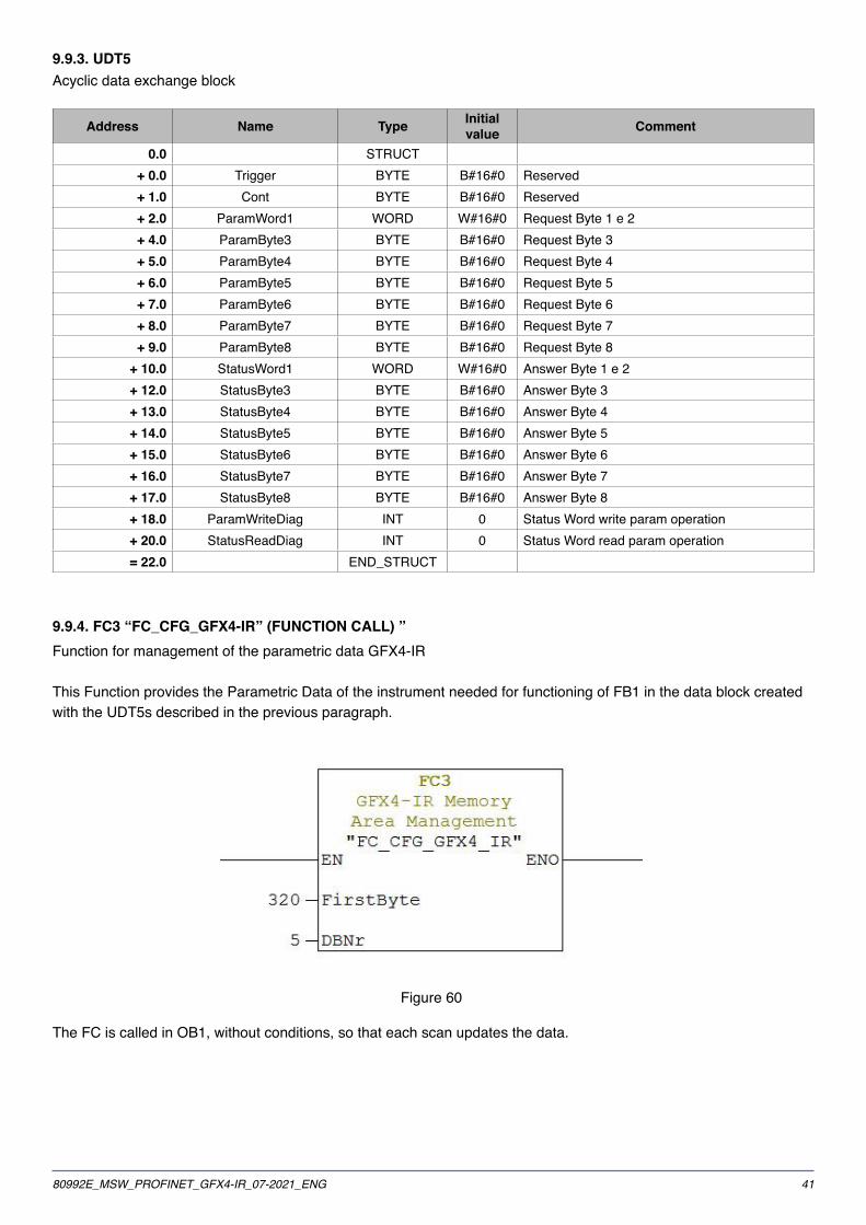
9�9�3� UDT5Acyclic data exchange block
Address Name Type Initialvalue Comment
0�0 STRUCT+ 0�0 Trigger BYTE B#16#0 Reserved+ 1�0 Cont BYTE B#16#0 Reserved+ 2�0 ParamWord1 WORD W#16#0 Request Byte 1 e 2+ 4�0 ParamByte3 BYTE B#16#0 Request Byte 3+ 5�0 ParamByte4 BYTE B#16#0 Request Byte 4+ 6�0 ParamByte5 BYTE B#16#0 Request Byte 5+ 7�0 ParamByte6 BYTE B#16#0 Request Byte 6+ 8�0 ParamByte7 BYTE B#16#0 Request Byte 7+ 9�0 ParamByte8 BYTE B#16#0 Request Byte 8
+ 10�0 StatusWord1 WORD W#16#0 Answer Byte 1 e 2+ 12�0 StatusByte3 BYTE B#16#0 Answer Byte 3+ 13�0 StatusByte4 BYTE B#16#0 Answer Byte 4+ 14�0 StatusByte5 BYTE B#16#0 Answer Byte 5+ 15�0 StatusByte6 BYTE B#16#0 Answer Byte 6+ 16�0 StatusByte7 BYTE B#16#0 Answer Byte 7+ 17�0 StatusByte8 BYTE B#16#0 Answer Byte 8+ 18�0 ParamWriteDiag INT 0 Status Word write param operation+ 20�0 StatusReadDiag INT 0 Status Word read param operation= 22�0 END_STRUCT
9�9�4� FC3 “FC_CFG_GFX4-IR” (FUNCTION CALL) ”Function for management of the parametric data GFX4-IR
This Function provides the Parametric Data of the instrument needed for functioning of FB1 in the data block createdwith the UDT5s described in the previous paragraph.
Figure 60
The FC is called in OB1, without conditions, so that each scan updates the data.

42 80992E_MSW_PROFINET_GFX4-IR_07-2021_ENG
Two input parameters are required:
1. FirstByte : (INT) the first memory address assigned in the GFX4-IR Hardware configuration.
2. DBNr : (INT) the number of the data block created with UDT5 for date exchange between GFX4-IR and PLC
Figure 61
First byte

4380992E_MSW_PROFINET_GFX4-IR_07-2021_ENG
9�3� Function blocks
All Function Blocks require a freely assignable instance DB. They must be called only on request and kept active untilcompletion of the operation�Typically, you set a Bit that enables the branch (EN) and is reset with the rising edge of the Done bit.
9�9�1� FB1 “FB_OP_GFX4_IR” (FUNCTION BLOCK) Manages basic Parametric Data operations for the GFX4-IR configuration.There are 4 operations: 1. Read bit (op. code 1) 2. Read word (op. code 3) 3. Write bit (op. code 5) 4. Write word (op. code 6)
Figure 62
The block requires 5 input parameters and responds with 4 output parameters.
Input parameters:1. DBNr (INT): the data block number assigned to the GFX4-IR to be interrogated or controlled.
2. SlaveNr (INT): the MODBUS address of the slave to be worked with.
3. OPCode (INT): the operation code that tells the function whether you want to read or write a word or a bit. The operation codes are:
● Read bit Operation Code: 1 ● Read word Operation Code: 3 ● Write bit Operation Code: 5 ● Write word Operation Code: 6
4. Address (INT): the address of the word or bit to be read or written. (Refer to the GFX4-IR manual for the MODBUS addresses of words and bits.)
5. INValue (INT): the value to be written in the selected word or bit. Of course, only values 1 and 0 are allowed when writing a bit. This parameter is ignored in read operations
Output parameters:- Done (BOOL): value is 1 when reading is done.- OUTValue (INT): value read in the specified word or bit.
In write operations, 1 is written if the action ended correctly or 0 if it ended with an error.- Error (BOOL): value is 1 when operation ended with an error.- ErrCode (INT): error code displayed: 1 Illegal function

44 80992E_MSW_PROFINET_GFX4-IR_07-2021_ENG
2 Illegal data address 3 Illegal data value 6 Slave device busy 9 Illegal number data 10 Read only data 20 Timeout Communication 21 Input value error
9�9�2� FB15 “FB_RCP_GFX4_IR” (FUNCTION BLOCK)Archives a set of parameters from a GFX4-IR in a DB or sends a set of parameters contained in a DB to a GFX4-IR.
Figure 63
Input parameters:- DB_GFX (INT): indicates the number (only the number in digits or an INT variable that contains its value) of the DB assigned to the GFX4-IR to be worked on.- DBIST (BLOCK_DB): indicates the name (use the symbolic name of the DB or the indication “DBxx” in full) of the instance DB of FB1 “OP_GFX4-IR” assigned to the GFX4-IR.- GFXNr (INT):the address of the GFX4-IR to be worked with.- RCP_DB (INT): the number of the DB in which to write or from which to read the data set.- Funct (BOOL): specifies the type of operation to be done: False = Store (save GFX4-IR parameters in the DB) True = Load (load parameters saved in DB in the GFX4-IR)- ParamNr (INT): the number of parameters to be saved/read.- ParamListDB (INT): the number of the DB in which each line specifies the modbus address of the parameters to be read/written
Output parameters:- Done (BOOL): value is 1 when the operation is done.- Error (BOOL): value is 1 when there was an error during write.- ErrorCode (INT): the error code is displayed in case of error: 1 Illegal function 2 Illegal data address 3 Illegal data value 6 Slave device busy 9 Illegal number data 10 Read only data 20 Timeout Communication 21 Input value error
- ErrorParamNr (INT): in case of error, you see the ordinal number in the DB with a list of the addresses of the parameter that caused the error.

4580992E_MSW_PROFINET_GFX4-IR_07-2021_ENG
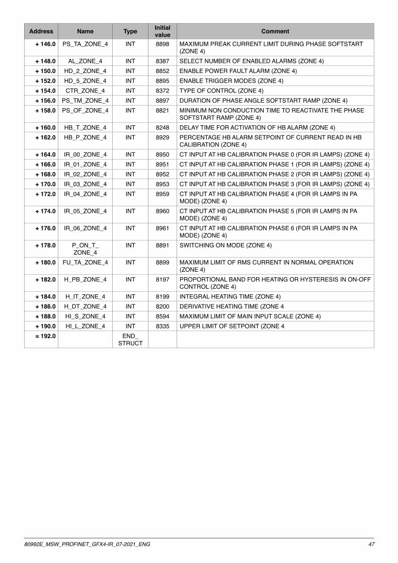
9�9�3� UDT7List of Modbus addresses of parameters used in FB15
Address Name Type Initialvalue Comment
0�0 STRUCT+ 0�0 TYP_ZONE_1 INT 1424 TYPE OF PROBE, SIGNAL AND SCALE OF MAIN INPUT (ZONE 1)+ 2�0 PS_TA_ZONE_1 INT 1730 MAXIMUM PREAK CURRENT LIMIT DURING PHASE SOFTSTART
(ZONE 1)+ 4�0 AL_ZONE_1 INT 1219 SELECT NUMBER OF ENABLED ALARMS (ZONE 1)+ 6�0 HD_2_ZONE_1 INT 1684 ENABLE POWER FAULT ALARM (ZONE 1)+ 8�0 HD_5_ZONE_1 INT 1727 ENABLE TRIGGER MODES (ZONE 1)
+ 10�0 CTR_ZONE_1 INT 1204 TYPE OF CONTROL (ZONE 1)+ 12�0 PS_TM_ZONE_1 INT 1729 DURATION OF PHASE ANGLE SOFTSTART RAMP (ZONE 1)+ 14�0 PS_OF_ZONE_1 INT 1653 MINIMUM NON CONDUCTION TIME TO REACTIVATE THE PHASE
SOFTSTART RAMP (ZONE 1)+ 16�0 HB_T_ZONE_1 INT 1080 DELAY TIME FOR ACTIVATION OF HB ALARM (ZONE 1)+ 18�0 HB_P_ZONE_1 INT 1761 PERCENTAGE HB ALARM SETPOINT OF CURRENT READ IN HB
CALIBRATION (ZONE 1)+ 20�0 IR_00_ZONE_1 INT 1782 CT INPUT AT HB CALIBRATION PHASE 0 (FOR IR LAMPS) (ZONE 1)+ 22�0 IR_01_ZONE_1 INT 1783 CT INPUT AT HB CALIBRATION PHASE 1 (FOR IR LAMPS) (ZONE 1)+ 24�0 IR_02_ZONE_1 INT 1784 CT INPUT AT HB CALIBRATION PHASE 2 (FOR IR LAMPS) (ZONE 1)+ 26�0 IR_03_ZONE_1 INT 1785 CT INPUT AT HB CALIBRATION PHASE 3 (FOR IR LAMPS) (ZONE 1)+ 28�0 IR_04_ZONE_1 INT 1791 CT INPUT AT HB CALIBRATION PHASE 4 (FOR IR LAMPS IN PA
MODE) (ZONE 1)+ 30�0 IR_05_ZONE_1 INT 1792 CT INPUT AT HB CALIBRATION PHASE 5 (FOR IR LAMPS IN PA
MODE) (ZONE 1)+ 32�0 IR_06_ZONE_1 INT 1793 CT INPUT AT HB CALIBRATION PHASE 6 (FOR IR LAMPS IN PA
MODE) (ZONE 1)+ 34�0 P_ON_T_
ZONE_1INT 1723 SWITCHING ON MODE (ZONE 1)
+ 36�0 FU_TA_ZONE_1 INT 1731 MAXIMUM LIMIT OF RMS CURRENT IN NORMAL OPERATION (ZONE 1)
+ 38�0 H_PB_ZONE_1 INT 1029 PROPORTIONAL BAND FOR HEATING OR HYSTERESIS IN ON-OFF CONTROL (ZONE 1)
+ 40�0 H_IT_ZONE_1 INT 1031 INTEGRAL HEATING TIME (ZONE 1)+ 42�0 H_DT_ZONE_1 INT 1032 DERIVATIVE HEATING TIME (ZONE 1)+ 44�0 HI_S_ZONE_1 INT 1426 MAXIMUM LIMIT OF MAIN INPUT SCALE (ZONE 1)+ 46�0 HI_L_ZONE_1 INT 1167 UPPER LIMIT OF SETPOINT (ZONE 1)+ 48�0 TYP_ZONE_2 INT 2448 TYPE OF PROBE, SIGNAL AND SCALE OF MAIN INPUT
(ZONE 2)+ 50�0 PS_TA_ZONE_2 INT 2754 MAXIMUM PREAK CURRENT LIMIT DURING PHASE SOFTSTART
(ZONE 2)+ 52�0 AL_ZONE_2 INT 2243 SELECT NUMBER OF ENABLED ALARMS (ZONE 2)+ 54�0 HD_2_ZONE_2 INT 2708 ENABLE POWER FAULT ALARM (ZONE 2)+ 56�0 HD_5_ZONE_2 INT 2751 ENABLE TRIGGER MODES (ZONE 2+ 58�0 CTR_ZONE_2 INT 2228 TYPE OF CONTROL (ZONE 2)+ 60�0 PS_TM_ZONE_2 INT 2753 DURATION OF PHASE ANGLE SOFTSTART RAMP (ZONE 2)+ 62�0 PS_OF_ZONE_2 INT 2677 MINIMUM NON CONDUCTION TIME TO REACTIVATE THE PHASE
SOFTSTART RAMP (ZONE 2)+ 64�0 HB_T_ZONE_2 INT 2104 DELAY TIME FOR ACTIVATION OF HB ALARM (ZONE 2)+ 66�0 HB_P_ZONE_2 INT 2785 PERCENTAGE HB ALARM SETPOINT OF CURRENT READ IN HB
CALIBRATION (ZONE 2)+ 68�0 IR_00_ZONE_2 INT 2806 CT INPUT AT HB CALIBRATION PHASE 0 (FOR IR LAMPS) (ZONE 2)+ 70�0 IR_01_ZONE_2 INT 2807 CT INPUT AT HB CALIBRATION PHASE 1 (FOR IR LAMPS) (ZONE 2)

46 80992E_MSW_PROFINET_GFX4-IR_07-2021_ENG
Address Name Type Initialvalue Comment
+ 72�0 IR_02_ZONE_2 INT 2808 CT INPUT AT HB CALIBRATION PHASE 2 (FOR IR LAMPS) (ZONE 2)+ 74�0 IR_03_ZONE_2 INT 2809 CT INPUT AT HB CALIBRATION PHASE 3 (FOR IR LAMPS) (ZONE 2)+ 76�0 IR_04_ZONE_2 INT 2815 CT INPUT AT HB CALIBRATION PHASE 4 (FOR IR LAMPS IN PA
MODE) (ZONE 2)+ 78�0 IR_05_ZONE_2 INT 2816 CT INPUT AT HB CALIBRATION PHASE 5 (FOR IR LAMPS IN PA
MODE) (ZONE 2)+ 80�0 IR_06_ZONE_2 INT 2817 CT INPUT AT HB CALIBRATION PHASE 6 (FOR IR LAMPS IN PA
MODE) (ZONE 2)+ 82�0 P_ON_T_
ZONE_2INT 2747 SWITCHING ON MODE (ZONE 2)
+ 84�0 FU_TA_ZONE_2 INT 2755 MAXIMUM LIMIT OF RMS CURRENT IN NORMAL OPERATION (ZONE 2)
+ 86�0 H_PB_ZONE_2 INT 2053 PROPORTIONAL BAND FOR HEATING OR HYSTERESIS IN ON-OFF CONTROL (ZONE 2)
+ 88�0 H_IT_ZONE_2 INT 2055 INTEGRAL HEATING TIME (ZONE 2)+ 90�0 H_DT_ZONE_2 INT 2056 DERIVATIVE HEATING TIME (ZONE 2)+ 92�0 HI_S_ZONE_2 INT 2450 MAXIMUM LIMIT OF MAIN INPUT SCALE (ZONE 2)+ 94�0 HI_L_ZONE_2 INT 2191 UPPER LIMIT OF SETPOINT (ZONE 2)+ 96�0 TYP_ZONE_3 INT 4496 TYPE OF PROBE, SIGNAL AND SCALE OF MAIN INPUT
(ZONE 3)+ 98�0 PS_TA_ZONE_3 INT 4802 MAXIMUM PREAK CURRENT LIMIT DURING PHASE SOFTSTART
(ZONE 3)+ 100�0 AL_ZONE_3 INT 4291 SELECT NUMBER OF ENABLED ALARMS (ZONE 3)+ 102�0 HD_2_ZONE_3 INT 4756 ENABLE POWER FAULT ALARM (ZONE 3)+ 104�0 HD_5_ZONE_3 INT 4799 ENABLE TRIGGER MODES (ZONE 3)+ 106�0 CTR_ZONE_3 INT 4276 TYPE OF CONTROL (ZONE 3)+ 108�0 PS_TM_ZONE_3 INT 4801 DURATION OF PHASE ANGLE SOFTSTART RAMP (ZONE 3)+ 110�0 PS_OF_ZONE_3 INT 4725 MINIMUM NON CONDUCTION TIME TO REACTIVATE THE PHASE
SOFTSTART RAMP (ZONE 3)+ 112�0 HB_T_ZONE_3 INT 4152 DELAY TIME FOR ACTIVATION OF HB ALARM (ZONE 3)+ 114�0 HB_P_ZONE_3 INT 4833 PERCENTAGE HB ALARM SETPOINT OF CURRENT READ IN HB
CALIBRATION (ZONE 3)+ 116�0 IR_00_ZONE_3 INT 4854 CT INPUT AT HB CALIBRATION PHASE 0 (FOR IR LAMPS) (ZONE 3)+ 118�0 IR_01_ZONE_3 INT 4855 CT INPUT AT HB CALIBRATION PHASE 1 (FOR IR LAMPS) (ZONE 3)+ 120�0 IR_02_ZONE_3 INT 4856 CT INPUT AT HB CALIBRATION PHASE 2 (FOR IR LAMPS) (ZONE 3)+ 122�0 IR_03_ZONE_3 INT 4857 CT INPUT AT HB CALIBRATION PHASE 3 (FOR IR LAMPS) (ZONE 3)+ 124�0 IR_04_ZONE_3 INT 4863 CT INPUT AT HB CALIBRATION PHASE 4 (FOR IR LAMPS IN PA
MODE) (ZONE 3)+ 126�0 IR_05_ZONE_3 INT 4864 CT INPUT AT HB CALIBRATION PHASE 5 (FOR IR LAMPS IN PA
MODE) (ZONE 3)+ 128�0 IR_06_ZONE_3 INT 4865 CT INPUT AT HB CALIBRATION PHASE 6 (FOR IR LAMPS IN PA
MODE) (ZONE 3)+ 130�0 P_ON_T_
ZONE_3INT 4795 SWITCHING ON MODE (ZONE 3)
+ 132�0 FU_TA_ZONE_3 INT 4803 MAXIMUM LIMIT OF RMS CURRENT IN NORMAL OPERATION (ZONE 3)
+ 134�0 H_PB_ZONE_3 INT 4101 PROPORTIONAL BAND FOR HEATING OR HYSTERESIS IN ON-OFF CONTROL (ZONE 3)
+ 136�0 H_IT_ZONE_3 INT 4103 INTEGRAL HEATING TIME (ZONE 3)+ 138�0 H_DT_ZONE_3 INT 4104 DERIVATIVE HEATING TIME (ZONE 3)+ 140�0 HI_S_ZONE_3 INT 4498 MAXIMUM LIMIT OF MAIN INPUT SCALE (ZONE 3)+ 142�0 HI_L_ZONE_3 INT 4239 UPPER LIMIT OF SETPOINT (ZONE 3)+ 144�0 TYP_ZONE_4 INT 8592 TYPE OF PROBE, SIGNAL AND SCALE OF MAIN INPUT
(ZONE 4)
4780992E_MSW_PROFINET_GFX4-IR_07-2021_ENG
Address Name Type Initialvalue Comment
+ 146�0 PS_TA_ZONE_4 INT 8898 MAXIMUM PREAK CURRENT LIMIT DURING PHASE SOFTSTART (ZONE 4)
+ 148�0 AL_ZONE_4 INT 8387 SELECT NUMBER OF ENABLED ALARMS (ZONE 4)+ 150�0 HD_2_ZONE_4 INT 8852 ENABLE POWER FAULT ALARM (ZONE 4)+ 152�0 HD_5_ZONE_4 INT 8895 ENABLE TRIGGER MODES (ZONE 4)+ 154�0 CTR_ZONE_4 INT 8372 TYPE OF CONTROL (ZONE 4)+ 156�0 PS_TM_ZONE_4 INT 8897 DURATION OF PHASE ANGLE SOFTSTART RAMP (ZONE 4)+ 158�0 PS_OF_ZONE_4 INT 8821 MINIMUM NON CONDUCTION TIME TO REACTIVATE THE PHASE
SOFTSTART RAMP (ZONE 4)+ 160�0 HB_T_ZONE_4 INT 8248 DELAY TIME FOR ACTIVATION OF HB ALARM (ZONE 4)+ 162�0 HB_P_ZONE_4 INT 8929 PERCENTAGE HB ALARM SETPOINT OF CURRENT READ IN HB
CALIBRATION (ZONE 4)+ 164�0 IR_00_ZONE_4 INT 8950 CT INPUT AT HB CALIBRATION PHASE 0 (FOR IR LAMPS) (ZONE 4)+ 166�0 IR_01_ZONE_4 INT 8951 CT INPUT AT HB CALIBRATION PHASE 1 (FOR IR LAMPS) (ZONE 4)+ 168�0 IR_02_ZONE_4 INT 8952 CT INPUT AT HB CALIBRATION PHASE 2 (FOR IR LAMPS) (ZONE 4)+ 170�0 IR_03_ZONE_4 INT 8953 CT INPUT AT HB CALIBRATION PHASE 3 (FOR IR LAMPS) (ZONE 4)+ 172�0 IR_04_ZONE_4 INT 8959 CT INPUT AT HB CALIBRATION PHASE 4 (FOR IR LAMPS IN PA
MODE) (ZONE 4)+ 174�0 IR_05_ZONE_4 INT 8960 CT INPUT AT HB CALIBRATION PHASE 5 (FOR IR LAMPS IN PA
MODE) (ZONE 4)+ 176�0 IR_06_ZONE_4 INT 8961 CT INPUT AT HB CALIBRATION PHASE 6 (FOR IR LAMPS IN PA
MODE) (ZONE 4)+ 178�0 P_ON_T_
ZONE_4INT 8891 SWITCHING ON MODE (ZONE 4)
+ 180�0 FU_TA_ZONE_4 INT 8899 MAXIMUM LIMIT OF RMS CURRENT IN NORMAL OPERATION (ZONE 4)
+ 182�0 H_PB_ZONE_4 INT 8197 PROPORTIONAL BAND FOR HEATING OR HYSTERESIS IN ON-OFF CONTROL (ZONE 4)
+ 184�0 H_IT_ZONE_4 INT 8199 INTEGRAL HEATING TIME (ZONE 4)+ 186�0 H_DT_ZONE_4 INT 8200 DERIVATIVE HEATING TIME (ZONE 4+ 188�0 HI_S_ZONE_4 INT 8594 MAXIMUM LIMIT OF MAIN INPUT SCALE (ZONE 4)+ 190�0 HI_L_ZONE_4 INT 8335 UPPER LIMIT OF SETPOINT (ZONE 4= 192�0 END_
STRUCT

48 80992E_MSW_PROFINET_GFX4-IR_07-2021_ENG
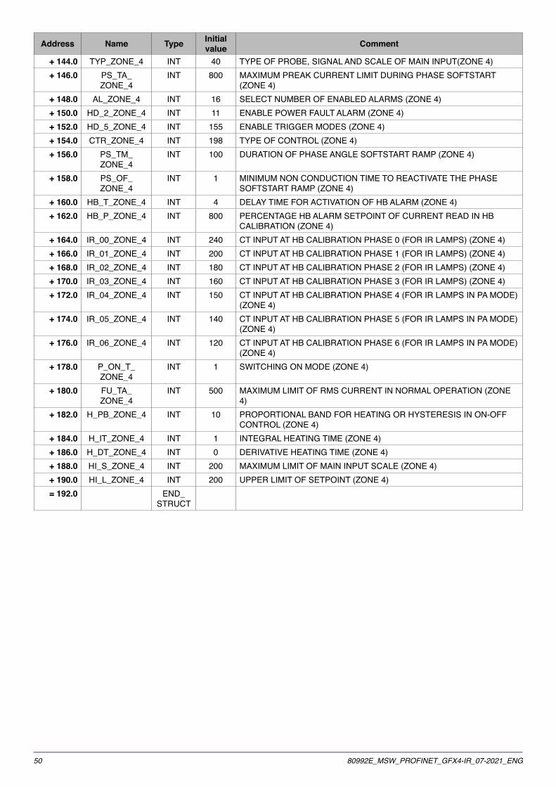
9�9�4� DB20List of parameters used in FB15
Address Name Type Initialvalue Comment
0�0 STRUCT+ 0�0 TYP_ZONE_1 INT 40 TYPE OF PROBE, SIGNAL AND SCALE OF MAIN INPUT(ZONE 1)+ 2�0 PS_TA_
ZONE_1INT 800 MAXIMUM PREAK CURRENT LIMIT DURING PHASE SOFTSTART
(ZONE 1)+ 4�0 AL_ZONE_1 INT 16 SELECT NUMBER OF ENABLED ALARMS (ZONE 1)+ 6�0 HD_2_ZONE_1 INT 11 ENABLE POWER FAULT ALARM (ZONE 1)+ 8�0 HD_5_ZONE_1 INT 155 ENABLE TRIGGER MODES (ZONE 1)
+ 10�0 CTR_ZONE_1 INT 198 TYPE OF CONTROL (ZONE 1)+ 12�0 PS_TM_
ZONE_1INT 100 DURATION OF PHASE ANGLE SOFTSTART RAMP (ZONE 1)
+ 14�0 PS_OF_ZONE_1
INT 1 MINIMUM NON CONDUCTION TIME TO REACTIVATE THE PHASE SOFTSTART RAMP (ZONE 1)
+ 16�0 HB_T_ZONE_1 INT 4 DELAY TIME FOR ACTIVATION OF HB ALARM (ZONE 1)+ 18�0 HB_P_ZONE_1 INT 800 PERCENTAGE HB ALARM SETPOINT OF CURRENT READ IN HB
CALIBRATION (ZONE 1)+ 20�0 IR_00_ZONE_1 INT 240 CT INPUT AT HB CALIBRATION PHASE 0 (FOR IR LAMPS) (ZONE 1)+ 22�0 IR_01_ZONE_1 INT 200 CT INPUT AT HB CALIBRATION PHASE 1 (FOR IR LAMPS) (ZONE 1)+ 24�0 IR_02_ZONE_1 INT 180 CT INPUT AT HB CALIBRATION PHASE 2 (FOR IR LAMPS) (ZONE 1)+ 26�0 IR_03_ZONE_1 INT 160 CT INPUT AT HB CALIBRATION PHASE 3 (FOR IR LAMPS) (ZONE 1)+ 28�0 IR_04_ZONE_1 INT 150 CT INPUT AT HB CALIBRATION PHASE 4 (FOR IR LAMPS IN PA MODE)
(ZONE 1)+ 30�0 IR_05_ZONE_1 INT 140 CT INPUT AT HB CALIBRATION PHASE 5 (FOR IR LAMPS IN PA MODE)
(ZONE 1)+ 32�0 IR_06_ZONE_1 INT 120 CT INPUT AT HB CALIBRATION PHASE 6 (FOR IR LAMPS IN PA MODE)
(ZONE 1)+ 34�0 P_ON_T_
ZONE_1INT 1 SWITCHING ON MODE (ZONE 1)
+ 36�0 FU_TA_ZONE_1
INT 500 MAXIMUM LIMIT OF RMS CURRENT IN NORMAL OPERATION (ZONE 1)
+ 38�0 H_PB_ZONE_1 INT 10 PROPORTIONAL BAND FOR HEATING OR HYSTERESIS IN ON-OFF CONTROL (ZONE 1)
+ 40�0 H_IT_ZONE_1 INT 1 INTEGRAL HEATING TIME (ZONE 1)+ 42�0 H_DT_ZONE_1 INT 0 DERIVATIVE HEATING TIME (ZONE 1)+ 44�0 HI_S_ZONE_1 INT 200 MAXIMUM LIMIT OF MAIN INPUT SCALE (ZONE 1)+ 46�0 HI_L_ZONE_1 INT 200 UPPER LIMIT OF SETPOINT (ZONE 1)+ 48�0 TYP_ZONE_2 INT 40 TYPE OF PROBE, SIGNAL AND SCALE OF MAIN INPUT(ZONE 2)+ 50�0 PS_TA_
ZONE_2INT 800 MAXIMUM PREAK CURRENT LIMIT DURING PHASE SOFTSTART
(ZONE 2)+ 52�0 AL_ZONE_2 INT 16 SELECT NUMBER OF ENABLED ALARMS (ZONE 2)+ 54�0 HD_2_ZONE_2 INT 11 ENABLE POWER FAULT ALARM (ZONE 2)+ 56�0 HD_5_ZONE_2 INT 155 ENABLE TRIGGER MODES (ZONE 2)+ 58�0 CTR_ZONE_2 INT 198 TYPE OF CONTROL (ZONE 2)+ 60�0 PS_TM_
ZONE_2INT 100 DURATION OF PHASE ANGLE SOFTSTART RAMP (ZONE 2)
+ 62�0 PS_OF_ZONE_2
INT 1 MINIMUM NON CONDUCTION TIME TO REACTIVATE THE PHASE SOFTSTART RAMP (ZONE 2)
+ 64�0 HB_T_ZONE_2 INT 4 DELAY TIME FOR ACTIVATION OF HB ALARM (ZONE 2)+ 66�0 HB_P_ZONE_2 INT 800 PERCENTAGE HB ALARM SETPOINT OF CURRENT READ IN HB
CALIBRATION (ZONE 2)+ 68�0 IR_00_ZONE_2 INT 240 CT INPUT AT HB CALIBRATION PHASE 0 (FOR IR LAMPS) (ZONE 2)

4980992E_MSW_PROFINET_GFX4-IR_07-2021_ENG
Address Name Type Initialvalue Comment
+ 70�0 IR_01_ZONE_2 INT 200 CT INPUT AT HB CALIBRATION PHASE 1 (FOR IR LAMPS) (ZONE 2)+ 72�0 IR_02_ZONE_2 INT 180 CT INPUT AT HB CALIBRATION PHASE 2 (FOR IR LAMPS) (ZONE 2)+ 74�0 IR_03_ZONE_2 INT 160 CT INPUT AT HB CALIBRATION PHASE 3 (FOR IR LAMPS) (ZONE 2)+ 76�0 IR_04_ZONE_2 INT 150 CT INPUT AT HB CALIBRATION PHASE 4 (FOR IR LAMPS IN PA MODE)
(ZONE 2)+ 78�0 IR_05_ZONE_2 INT 140 CT INPUT AT HB CALIBRATION PHASE 5 (FOR IR LAMPS IN PA MODE)
(ZONE 2)+ 80�0 IR_06_ZONE_2 INT 120 CT INPUT AT HB CALIBRATION PHASE 6 (FOR IR LAMPS IN PA MODE)
(ZONE 2)+ 82�0 P_ON_T_
ZONE_2INT 1 SWITCHING ON MODE (ZONE 2)
+ 84�0 FU_TA_ZONE_2
INT 500 MAXIMUM LIMIT OF RMS CURRENT IN NORMAL OPERATION (ZONE 2)
+ 86�0 H_PB_ZONE_2 INT 10 PROPORTIONAL BAND FOR HEATING OR HYSTERESIS IN ON-OFF CONTROL (ZONE 2)
+ 88�0 H_IT_ZONE_2 INT 1 INTEGRAL HEATING TIME (ZONE 2)+ 90�0 H_DT_ZONE_2 INT 0 DERIVATIVE HEATING TIME (ZONE 2)+ 92�0 HI_S_ZONE_2 INT 200 MAXIMUM LIMIT OF MAIN INPUT SCALE (ZONE 2)+ 94�0 HI_L_ZONE_2 INT 200 UPPER LIMIT OF SETPOINT (ZONE 2)+ 96�0 TYP_ZONE_3 INT 40 TYPE OF PROBE, SIGNAL AND SCALE OF MAIN INPUT(ZONE 3)+ 98�0 PS_TA_
ZONE_3INT 800 MAXIMUM PREAK CURRENT LIMIT DURING PHASE SOFTSTART
(ZONE 3)+ 100�0 AL_ZONE_3 INT 16 SELECT NUMBER OF ENABLED ALARMS (ZONE 3)+ 102�0 HD_2_ZONE_3 INT 11 ENABLE POWER FAULT ALARM (ZONE 3)+ 104�0 HD_5_ZONE_3 INT 155 ENABLE TRIGGER MODES (ZONE 3)+ 106�0 CTR_ZONE_3 INT 198 TYPE OF CONTROL (ZONE 3)+ 108�0 PS_TM_
ZONE_3INT 100 DURATION OF PHASE ANGLE SOFTSTART RAMP (ZONE 3)
+ 110�0 PS_OF_ZONE_3
INT 1 MINIMUM NON CONDUCTION TIME TO REACTIVATE THE PHASE SOFTSTART RAMP (ZONE 3)
+ 112�0 HB_T_ZONE_3 INT 4 DELAY TIME FOR ACTIVATION OF HB ALARM (ZONE 3)+ 114�0 HB_P_ZONE_3 INT 800 PERCENTAGE HB ALARM SETPOINT OF CURRENT READ IN HB
CALIBRATION (ZONE 3)+ 116�0 IR_00_ZONE_3 INT 240 CT INPUT AT HB CALIBRATION PHASE 0 (FOR IR LAMPS) (ZONE 3)+ 118�0 IR_01_ZONE_3 INT 200 CT INPUT AT HB CALIBRATION PHASE 1 (FOR IR LAMPS) (ZONE 3)+ 120�0 IR_02_ZONE_3 INT 180 CT INPUT AT HB CALIBRATION PHASE 2 (FOR IR LAMPS) (ZONE 3)+ 122�0 IR_03_ZONE_3 INT 160 CT INPUT AT HB CALIBRATION PHASE 3 (FOR IR LAMPS) (ZONE 3)+ 124�0 IR_04_ZONE_3 INT 150 CT INPUT AT HB CALIBRATION PHASE 4 (FOR IR LAMPS IN PA MODE)
(ZONE 3)+ 126�0 IR_05_ZONE_3 INT 140 CT INPUT AT HB CALIBRATION PHASE 5 (FOR IR LAMPS IN PA MODE)
(ZONE 3)+ 128�0 IR_06_ZONE_3 INT 120 CT INPUT AT HB CALIBRATION PHASE 6 (FOR IR LAMPS IN PA MODE)
(ZONE 3)+ 130�0 P_ON_T_
ZONE_3INT 1 SWITCHING ON MODE (ZONE 3)
+ 132�0 FU_TA_ZONE_3
INT 500 MAXIMUM LIMIT OF RMS CURRENT IN NORMAL OPERATION (ZONE 3)
+ 134�0 H_PB_ZONE_3 INT 10 PROPORTIONAL BAND FOR HEATING OR HYSTERESIS IN ON-OFF CONTROL (ZONE 3)
+ 136�0 H_IT_ZONE_3 INT 1 INTEGRAL HEATING TIME (ZONE 3)+ 138�0 H_DT_ZONE_3 INT 0 DERIVATIVE HEATING TIME (ZONE 3)+ 140�0 HI_S_ZONE_3 INT 200 MAXIMUM LIMIT OF MAIN INPUT SCALE (ZONE 3)+ 142�0 HI_L_ZONE_3 INT 200 UPPER LIMIT OF SETPOINT (ZONE 3)
50 80992E_MSW_PROFINET_GFX4-IR_07-2021_ENG
Address Name Type Initialvalue Comment
+ 144�0 TYP_ZONE_4 INT 40 TYPE OF PROBE, SIGNAL AND SCALE OF MAIN INPUT(ZONE 4)+ 146�0 PS_TA_
ZONE_4INT 800 MAXIMUM PREAK CURRENT LIMIT DURING PHASE SOFTSTART
(ZONE 4)+ 148�0 AL_ZONE_4 INT 16 SELECT NUMBER OF ENABLED ALARMS (ZONE 4)+ 150�0 HD_2_ZONE_4 INT 11 ENABLE POWER FAULT ALARM (ZONE 4)+ 152�0 HD_5_ZONE_4 INT 155 ENABLE TRIGGER MODES (ZONE 4)+ 154�0 CTR_ZONE_4 INT 198 TYPE OF CONTROL (ZONE 4)+ 156�0 PS_TM_
ZONE_4INT 100 DURATION OF PHASE ANGLE SOFTSTART RAMP (ZONE 4)
+ 158�0 PS_OF_ZONE_4
INT 1 MINIMUM NON CONDUCTION TIME TO REACTIVATE THE PHASE SOFTSTART RAMP (ZONE 4)
+ 160�0 HB_T_ZONE_4 INT 4 DELAY TIME FOR ACTIVATION OF HB ALARM (ZONE 4)+ 162�0 HB_P_ZONE_4 INT 800 PERCENTAGE HB ALARM SETPOINT OF CURRENT READ IN HB
CALIBRATION (ZONE 4)+ 164�0 IR_00_ZONE_4 INT 240 CT INPUT AT HB CALIBRATION PHASE 0 (FOR IR LAMPS) (ZONE 4)+ 166�0 IR_01_ZONE_4 INT 200 CT INPUT AT HB CALIBRATION PHASE 1 (FOR IR LAMPS) (ZONE 4)+ 168�0 IR_02_ZONE_4 INT 180 CT INPUT AT HB CALIBRATION PHASE 2 (FOR IR LAMPS) (ZONE 4)+ 170�0 IR_03_ZONE_4 INT 160 CT INPUT AT HB CALIBRATION PHASE 3 (FOR IR LAMPS) (ZONE 4)+ 172�0 IR_04_ZONE_4 INT 150 CT INPUT AT HB CALIBRATION PHASE 4 (FOR IR LAMPS IN PA MODE)
(ZONE 4)+ 174�0 IR_05_ZONE_4 INT 140 CT INPUT AT HB CALIBRATION PHASE 5 (FOR IR LAMPS IN PA MODE)
(ZONE 4)+ 176�0 IR_06_ZONE_4 INT 120 CT INPUT AT HB CALIBRATION PHASE 6 (FOR IR LAMPS IN PA MODE)
(ZONE 4)+ 178�0 P_ON_T_
ZONE_4INT 1 SWITCHING ON MODE (ZONE 4)
+ 180�0 FU_TA_ZONE_4
INT 500 MAXIMUM LIMIT OF RMS CURRENT IN NORMAL OPERATION (ZONE 4)
+ 182�0 H_PB_ZONE_4 INT 10 PROPORTIONAL BAND FOR HEATING OR HYSTERESIS IN ON-OFF CONTROL (ZONE 4)
+ 184�0 H_IT_ZONE_4 INT 1 INTEGRAL HEATING TIME (ZONE 4)+ 186�0 H_DT_ZONE_4 INT 0 DERIVATIVE HEATING TIME (ZONE 4)+ 188�0 HI_S_ZONE_4 INT 200 MAXIMUM LIMIT OF MAIN INPUT SCALE (ZONE 4)+ 190�0 HI_L_ZONE_4 INT 200 UPPER LIMIT OF SETPOINT (ZONE 4)= 192�0 END_
STRUCT

5180992E_MSW_PROFINET_GFX4-IR_07-2021_ENG

GEFRAN S�p�A�via Sebina, 74 - 25050 Provaglio d’Iseo (BS) Italy
Tel. 030 98881 - Fax 030 9839063 - www.gefran.com