code 80291I / Edition 12 01/2015 ITA
76
2500 CONFIGURABLE CONTROLLER Software version 1.6x code 80291I / Edition 12 - 01/2015 ITA INSTALLATION AND OPERATION MANUAL GENERAL INDEX Page Graphic symbols used 2 1 Preliminary instructions 2 General description 2 Basic version controller 2 Options 2 Operator interface 3 Electrical interface 3 Preliminary warnings 3 2 Installation and connection 4 Electrical power supply 4 Notes concerning electrical safety and Electromagnetic compatibility 4 Advice for correct installation for EMC 5 Instrument power supply 5 Inputs and outputs connection 5 Dimensions and cut-out 6 Installation with panel mounting 6 Warnings and instructions for mounting to the panel 6 Nominal ambient conditions 6 Electrical connections 7 Examples 17 3 Functions 20 Operator interface 20 General operating notes 22 Navigating through the controller menu 23 4 Configuration and programming 26 Application notes 48 HOLD function 48 Alarms 48 Control actions 48 Manual tuning 49 Multiset function,Set gradient 49 Page Twin setpoint application (Ramp + Hold + Time expiration alarm) 49 Software ON/OFF switching function 50 Self-Tuning 50 Auto-Tuning 51 Controls 51 Heating/Cooling control with Relative gain 51 String assigned to an alarm 52 Maths functions 53 Ratio controller 54 5 Technical specifications 55 6 Maintenance 56 Cleaning the controller 56 Repairs 56 Checking the jumpers 56 Troubleshooting Guide 57 7 Technical-Commercial information 57 Order code 57 Accessories RS232/TTL interface for Gefran Instrument configuration 57 Appendix 58 Block Diagrams 65 Functional diagram 66 Examples of custom linearization 76 The contents of each section are summarized immediately following the section heading 1 80291I_MHW_2500_01-2015_ENG
Transcript of code 80291I / Edition 12 01/2015 ITA

2500 CONFIGURABLE CONTROLLER
Software version 1.6x
code 80291I / Edition 12 - 01/2015 ITA
INSTALLATION ANDOPERATION MANUAL
GENERAL INDEX Page Graphic symbols used 21 Preliminary instructions 2 General description 2 Basic version controller 2 Options 2 Operator interface 3 Electrical interface 3 Preliminary warnings 3
2 Installation and connection 4 Electrical power supply 4 Notes concerning electrical safety and Electromagnetic compatibility 4 Advice for correct installation for EMC 5 Instrument power supply 5 Inputs and outputs connection 5 Dimensions and cut-out 6 Installation with panel mounting 6 Warnings and instructions for mounting to the panel 6 Nominal ambient conditions 6 Electrical connections 7 Examples 17
3 Functions 20 Operator interface 20 General operating notes 22 Navigating through the controller menu 23
4 Configuration and programming 26 Application notes 48 HOLD function 48 Alarms 48 Control actions 48 Manual tuning 49 Multiset function,Set gradient 49
Page Twin setpoint application (Ramp + Hold + Time expiration alarm) 49 Software ON/OFF switching function 50 Self-Tuning 50 Auto-Tuning 51 Controls 51 Heating/Cooling control with Relative gain 51 String assigned to an alarm 52 Maths functions 53 Ratio controller 54
5 Technical specifications 55
6 Maintenance 56 Cleaning the controller 56 Repairs 56 Checking the jumpers 56 Troubleshooting Guide 57
7 Technical-Commercial information 57 Order code 57
Accessories RS232/TTL interface for Gefran Instrument configuration 57
Appendix 58
Block Diagrams 65
Functional diagram 66
Examples of custom linearization 76
The contents of each section are summarized immediately following the section heading
180291I_MHW_2500_01-2015_ENG

Graphic symbols usedTo distinguish between the type and importance of the information provided in these instructions for use, graphic symbols have been used as a reference to make interpreting the information clearer.
Indicates the contents of the various manual sections, the general warnings, notes, and other points to which the reader’s attention should be drawn.
Indicates a particularly delicate situation that could affect the safety and correct working operation of the controller, or a rule that must be strictly obser-ved to avoid dangerous situations
Indicates a condition of risk for the safety of the user, due to the presence of dangerous voltages at the points shown
Indicates a suggestion based on the experience of the GEFRAN Technical Staff, which could prove especially useful under given circumstances
Indicates a reference to Detailed Technical Documents available on the GEFRAN web site www.gefran.com
1 • PRELIMINARY INSTRUCTIONS This section contains information and warnings of a
general nature which should be read before proceeding with controller installation, configuration and use.
General DescriptionThe instrument is appropriate for acquisition and control of systems with high variation speed. It has two main analog inputs for many applications, including differential measure-ments.The inputs can be configured from the keyboard and accept standard linear signals (as well as custom linearized signals), signals from pressure probes, load cells, potentio-meters, TC, RDT.They represent an exclusive combination of performance, reliability and applicational flexibility. In particular, this new line of Gefran temperature controllers is the ideal solution for application in sectors where performance and service continuity are important, including:• pressurecontrolsonextrusionandinjectionpress lines for plastics• differentialpressurecontrol• strengthcontrolontextile,paper,plasticfilm production lines• tensioncontrolonwindingstations
The controller also has 4 digital inputs for functions such as reset, calibration, man/auto, loc/rem, hold, raise/lower (moto-potentiometer function), parameter set selection, setpoint selection. The outputs (up to 4) are relay type, with alarm function.
Up to 3 optional high-resolution (optically isolated) analog outputs are also available for functions such as control, ana-log retransmission of peak values, remote setpoints, devia-tion, alarm setpoints, differential value.
Basic Version Controller (mod. 2500-0-0-0-0-0-X)• 1 universal input for strain gauge, potentiometer, thermocouples TC, RTD 2/3 wires and linear thermocouples, supplied with current and voltage with accuracy better than 0,1% f.s.• 2 auxiliary inputs for linear on current and voltage, potentiometers• 1 power supply for transmitters• 4 configurable digital inputs NPN or PNP• 1 control analog output• 1 power supply probe selectable for strain gauge, potentiometers and transmitters• 4 outputs: OUT1, OUT2, OUT3, OUT4 relay
Options• 2th universal input (useful for differential measurements)• 2th control analog output• 1 retransmission analog output• 4 digital inputs/outputs with configurable function• 1 serial optoisolated RS485 interface
2 80291I_MHW_2500_01-2015_ENG

Operator InterfaceAll the operator interface devices are concentrated on the controller faceplate with IP54 level protection.• 6buttonstobeusedformanualregulation/configuration/ selection• 1red/greenfive-digitdisplays(processvariable)• 2greenfive-digitdisplays (Set point and configuration parameter)• 5redledforconfigurableindication• 2bargraphredwithprogrammablefunctionality
Electrical InterfaceAll connection terminals (power supply, inputs, outputs, options) are grouped together on the back of the controller. For technical specifications and performance details refer to Section 5 “Technical Specifications”.
Preliminary Warnings The following preliminary warnings should be read
before installing and using the series 2500 controller. This will allow the controller to be put into service more quickly and will avoid certain problems which
may mistakenly be interpreted as malfunctions or limitations of the controller.• Immediatelyafterunpackingthecontroller,makeanoteof the order code and the other identification data given on the label affixed to the outside of the container and copy them to the table below.
These details must always be kept close at hand and referred to the personnel involved in the event of help from Gefran Customer Service Assistance.• Check also that the controller is complete and has not been damaged at all during transit, and that the package contains not only the controller and these Instructions for Use, but also the two brackets for fixing to the panel and the dust protection seal - see: Installation with Panel Fixing in Section 2. Any inconsistencies, omissions or evident signs of damage should be reported immediately to your Gefran sales agent.• Checkthattheordercodecorrespondswiththeconfigura- tion requested for the application the controller is needed for, referring to Section 7: “Technical - Commercial Information”.• No.andTypeofInputs/Outputsavailable• Presenceofthenecessaryoptionsandaccessories• Mainsvoltagesupply
Example: 2500 – 0 – 1 – 0 – 0 – 2 – 1 Model 2500 controller Single main input Digital Input/Outputs 5...8 Single continuous control output ±10V (0/4...20mA) None retransmission output Digital Communication: RS485 Power supply 100...240Vac/dc• Beforeinstallingtheseries2500controlleronthecontrol panel of the machine or host system, refer to the para- graph “Dimensions and Cut-out” in Section 2 “Installation and Connection”.• WhereconfigurationbyPCisprovidedfor,makesure the interface RS232 cable is available and the CD-ROM containing the WINSTRUM software. For the order code refer to Section 7 “Technical - Commercial Information”.
Users and/or system integrators who wish to know more about the concepts of serial communication between standard PC and/or Gefran Industrial PC
and Gefran Programmable Instruments, can access the various technical reference Documents in Adobe Acrobat format available in the Download section of the Gefran Web Site www.gefran.com including:
•SerialCommunication •MODBusProtocol
In the same Download section of the Gefran Web Site www.gefran.com the 2500 Controller reference manual is available in Adobe Acrobat format, containing a detailed description of all the adjustable parameters and procedures.In the event of presumed instrument malfunction, before contacting Gefran Technical Service Assistance, refer to the Troubleshooting Guide given in Section 6 “Maintenance”, and ifnecessary refer to the F.A.Q. Section (Frequently Asked Questions) on the Gefran Web Site www.gefran.com
SN: ......................... (Serial n°)CODE: ......................... (Finished product code)TYPE: ......................... (Order Code)SUPPLY: ......................... (Type of electrical power supply)VERS: ......................... ((Software version)
380291I_MHW_2500_01-2015_ENG

2 • INSTALLATION AND CONNECTION This section contains the instructions necessary for correct installation of the 2500 controllers into the machine control panel or the host system and for
correct connection of the controller power supply, inputs, outputs and interfaces.
Before proceeding with installation read the following warnings carefully! Remember that lack of observation of these war- nings could lead to problems of electrical safety and electromagnetic compatibility, as well as
invalidating the warranty.
Electrical power supply
• thecontrollerisNOTequippedwithanOn/Offswitch:the user must provide a two-phase disconnecting switch that conforms to the required safety standards (CE marking), to cut off the power supply upstream of the controller. The switch must be located in the immediate vicinity of the controller and must be within easy reach of the operator. One switch may control more than one controller.
• ifthecontrollerisconnectedtoNOTisolatedelectrical equipment (e.g. thermocouples), the earth connection must be made with a specific conductor to prevent the connection itself from coming directly through the machine structure.
• ifthecontrollerisusedinapplicationswithriskofdamage to persons, machinery or materials, it is essential to
connect it up to auxiliary alarm equipment. It is advisable to make sure that alarm signals are also triggered during normal operation. The controller must NOT be installed in flammable or explosive environments; it may be connected to equipment operating in such atmospheres only by means of appropriate and adequate types of interface, conforming to the applicable safety standards.
Notes Concerning Electrical Safety and Electromagnetic Compatibility:
CE MARKING:The instrument conforms to the European Directives 2004/108/CE and 2006/95/CE with reference to the generic standards: EN 61000-6-2 (immunity in industrial environment) EN 61000-6-3 (emission in residential environment) EN 61010-1 (safety).Series 2500 temperature controllers are mainly designed to operate in industrial environments, installed on the switch boards or control panels of productive process machines or plants.As regards electromagnetic compatibility, the strictest gene-ric standards have been adopted, as indicated in the table below.
EMC conformity has been tested with the following con-nections.
Function Cable type LengthPower supply cable 1mm2 1mRelay output cables 1mm2 3,5mSerial connection wire 0,35mm2 3,5mThermocouple input 0,8mm2 compensated 5mStrain gauge input, potentiometers, linears, “PT100” temperature resistance 1mm2 3mControl and retransmission analog outputs 1mm2 3,5mDigital Inputs / Outputs 1mm2 3,5m
4 80291I_MHW_2500_01-2015_ENG

Advice for Correct Installation for EMC
Instrument power supply
• The power supply to the electronic equipment on the switchboards must always come directly from an isola- tion device with a fuse for the instrument part.• Theelectronicinstrumentsandelectromechanicalpower devices such as relays, contactors, solenoid valves, etc., must always be powered by separate lines.• Whentheelectronicinstrumentpowersupplyisstrongly disturbed by the commutation of transistor or power units or motors, an isolation transformer should be used for the controllers only, earthing the screen.• Itisessentialthattheplanthasagoodearthconnection: - the voltage between neutral and earth must not be >1V -theOhmicresistancemustbe<6Ω;• Ifthemainsvoltagefluctuatesstrongly,useavoltage stabilizer.• Intheproximityofhighfrequencygeneratorsorarcwel- ders, use adequate mains filters.• Thepowersupplylinesmustbeseparatefromthe instrument input and output ones.
Inputs and outputs connection
• Theexternallyconnectedcircuitsmustbedoublyisolated.• Toconnecttheanalogueinputsandanalogoutputsthe following is necessary: - physically separate the input cables from those of the power supply, the outputs and the power connections. - use woven and screened cables, with the screen earthed in one point only.• Toconnecttherelayoutputs(contactors,solenoidvalves, motors, fans, etc.), fit RC groups (resistance and coden- sers in series) in parallel to the inductive loads that ope- rate in Alternating Current. (Note: all the condensers must conform to VDE (class X2) standards and withstand a voltage of at least 220V AC. The resistances must be at least 2W).• Fita1N4007diodeinparallelwiththecoiloftheinducti- ve loads that operate in Direct Current.
GEFRAN S.p.A. declines all responsibility for any damage to persons or property caused by tampering, neglect, improper use or any use which does not conform to the characteristics
of the controller and to the indications given in these Instructions for Use.
Generic standards, emission standard for residentialcommercial and light industrial environmentsGeneric standards emission standard for industrial environmentEmission AC mainsRadiated emission
EN 61000-6-3
EN 61000-6-4 EN 61000-6-3EN 61000-6-4
CISPR-16-1-4CISPR-16-2-3CEI R210-010
Classe BClasse A
EMC EMISSION
EMC IMMUNITYGeneric standards, immunity standard of industrial environmentsElectrostatic discharge immunity
Radiated radio frequency electromagnetic field immunity test
Conducted disturbances immunity
Electrical fast transient/burst immunity test
Surge immunity test
Power frequency magnetic field immunity testVoltage dips, short interruptions and voltage immunity tests
EN 61000-6-2EN 61000-4-2
EN 61000-4-3 +A1
EN 61000-4-6
EN 61000-4-4
EN 61000-4-5
EN 61000-4-8EN 61000-4-11
± 4 kV contact discharge± 8 kV air discharge10 V/m amplitude modulated80 MHz-1 GHz10 V/m amplitude modulated1.4 GHz-2 GHz10 V/m amplitude modulated0.15 MHz-80 MHz± 2 kV power line± 2 kV signal linePower line-line ± 1 kVPower line-earth ± 2 kVSignal line-earth ± 1 kV100 A/m100%U, 70%U, 40%U,
LOW VOLTAGE DIRECTIVE SAFETYSafety requirements for electrical equipment for measurement,control and laboratory use
EN 61010-1
580291I_MHW_2500_01-2015_ENG

Dimensions and cut-out96 115
108 96
10
92
92
115
170
Installation with panel mountingAs well as the actual controller and these instructions for use, the controller package also contains:
•n°2panelfixingbrackets(A)•n°1protectivesealagainstdustandwaterspray(B)
Fit the controller to the panel as shown in the figure.
Warnings and instructions for mounting to the panel
Instructions for installation category II, pollution level 2, double isolation.
• Theequipmentisintendedforpermanentindoorinstalla- tions within their own enclosure or panel mounted enclosing the rear housing and exposed terminals on the back.• only for models with 20...27Vac/dc power supply: supply from Class 2 or low voltage limited energy source• thepowersupplylinesmustbeseparatefromthe controller input and output ones• grouptheinstrumentstogetherkeepingthemseparate from the powered part of the relay• donotinstallhigh-powerremoteswitches,contactors, relays, thyristor power units (especially the “phase angle” type), motors, etc. in the same switchboard• avoiddust,humidity,corrosivegassesandheatsources• donotblocktheventilationholes:theworkingtempera- ture must be between 0...50°C• surroundingair:50°C• use60/75°Ccopper(Cu)conductoronly,wiresizerange 2x N. 22 - 14AWG, Solid/Stranded• useterminaltighteningtorque0.5Nm
Nominal ambient conditions
Before supplying the Controller with power, make sure that the mains voltage is the same as that shown in the last number of the order code.
Example: 2500 – x – x – x – x – x – 1 = 100..240Vac/dc 2500 – x – x – x – x – x – 0 = 20..27Vac/dc
A
B
A
B
Altitude Up to 2000mWorking/storage 0..50°C/-20...70°Ctemperature Non condensing 20...85%relative humidity
6 80291I_MHW_2500_01-2015_ENG

Electrical Connections (Mod. 2500 - 0 - x - x - x - x - x)
B A 1
11
24
33
1
11
22
12
2
3
4
5
6
7
8
9
10
25
26
27
28
29
30
31
3213
14
15
16
17
18
19
20
21
10
9
8
7
6
5
4
3
2
When making connections, always use wire appropriate to the voltage and current limits indicated in Section 5 – Technical Characteristics. If the Controller has faston contacts, they must be protected and isolated.
If it has screw contacts, the wires must be attached at least in pairs
B A 1
11
24
33
1
11
22
12
2
3
4
5
6
7
8
9
10
25
26
27
28
29
30
31
3213
14
15
16
17
18
19
20
21
10
9
8
7
6
5
4
3
2
B A 1
11
24
33
1
11
22
12
2
3
4
5
6
7
8
9
10
25
26
27
28
29
30
31
3213
14
15
16
17
18
19
20
21
10
9
8
7
6
5
4
3
2
- 0V
+ IN4 Lin
- 0V
+ IN3 Lin
+ 24V transmitter supply
- probe supply+
-CAL1 Rtd1 +
- IN1+
~power supply
90-260Vac / 18-30Vac/dc~
c (OUT 1, OUT 2)
OUT 2
OUT 3
c (OUT 3, OUT 4)
OUT 4
c (DI1, DI2)
DI2
DI1
OUT 1
c (CO1, CO2)
+ output CO2
+ output CO1
DI / OUT 8
DI / OUT 7
DI / OUT 6
DI / OUT 5
Vext DI / OUT 5...8
DI4
DI3
c (DI3, DI4, DI / OUT 5...8)
2-wires 4-wires
Rx +
GND RX -
A(+) Tx +
B(-) Tx -
- OUT W+
RS485
GND
Tx
Rx
RS232
780291I_MHW_2500_01-2015_ENG

1
2
3
4
7
9/11
+
+
+
S
Input IN1 TC - Thermocouple
IN1 linear input with three-wire transmitter powered by instrument
IN1
Transmitter power supply
PT100 for possible compensation of external cold junction
Available thermocouples: J, K, R, S, T (B,E, N, L, U, G, D, C possible by inserting custom linearization) - Respect polarity - For extensions, use compensated wire sui-table to the TC utilized
Select the probe accordiing to transmitter type
IN1 linear input with two-wire transmitter powered by instrument
1
2
3
4
7
9/11
+
+
+IN1
24V Transmitter power supply
A
A
A
1
2
3
4
5
6
+
T
IN1
4...20mA
24V
Electrical Connections (Mod. 2500 - 0 - x - x - x - x - x)
8 80291I_MHW_2500_01-2015_ENG

IN1 Linear input (I)
1
2
+
Linear input in DC0/4...20mA,Ri=50Ω
IN1 Linear input (V)
1
2
+
Linear input in DC±60mV Ri>10MΩ±100mV Ri>10MΩ±1V Ri>2MΩ±5V Ri>2MΩ±10V Ri>2MΩ
IN1 Linear input PT100
1
2
3
4
5
6
1
2
3
4
T T
+
2-wire connection 3-wire connection
Use wires with adequate sec-tion (min 1 mm2)
IN1
IN1
IN1
IN1 potentiometer input
1
2
3
4
5
6
+
+
IN1
A
A
A
A
IN1 Strain-gauge input 4/6 wires
1
2
3
4
5
6
+
+
+
Strain-gauge sensitivity 1,5...4mV/VProbe power supply 5/10V
GreenWhite
Black or Yellow
Red
BlueBrown orOrange
CALCAL
- Exc+ Exc
IN1
A
PotentiometerR≥100Ω
Probe power supply
2,5V
Electrical Connections (Mod. 2500 - 0 - x - x - x - x - x)
980291I_MHW_2500_01-2015_ENG

B A 1
11
24
33
1
11
22
12
2
3
4
5
6
7
8
9
10
25
26
27
28
29
30
31
3213
14
15
16
17
18
19
20
21
10
9
8
7
6
5
4
3
2
B A 1
11
24
33
1
11
22
12
2
3
4
5
6
7
8
9
10
25
26
27
28
29
30
31
3213
14
15
16
17
18
19
20
21
10
9
8
7
6
5
4
3
2
B A 1
11
24
33
1
11
22
12
2
3
4
5
6
7
8
9
10
25
26
27
28
29
30
31
3213
14
15
16
17
18
19
20
21
10
9
8
7
6
5
4
3
2
- 0V
+ IN4 Lin
- 0V
+ IN3 Lin
+ 24V transmitter supply
- probe supply+
- IN2+
- IN1+
~power supply
90-260Vac / 18-30Vac/dc~
c (OUT 1, OUT 2)
OUT 2
OUT 3
c (OUT 3, OUT 4)
OUT 4
c (DI1, DI2)
DI2
DI1
OUT 1
c (CO1, CO2)
+ uscita CO2
+ uscita CO1
DI / OUT 8
DI / OUT 7
DI / OUT 6
DI / OUT 5
Vext DI / OUT 5...8
DI4
DI3
c (DI3, DI4, DI / OUT 5...8)
- -CAL2 Rtd2 Al.P2 + +
- -CAL1 Rtd1 Al.P1 + +
Electrical Connections (Mod. 2500 - 1 - x - x - x - x - x)
2 wires 4 wires Rx +
GND RX -
A(+) Tx +
B(-) Tx -
- OUT W+
RS485
GND
Tx
Rx
RS232
10 80291I_MHW_2500_01-2015_ENG

1
2
3
4
7
9/11
+
+
+
S
1
2
3
4
7
9/11
+
+
+
IN2 TC - Thermocouple input
3
26 4
27
+
T
(*) PT100 for possible compensation of remote cold junction
IN1 TC - Thermocouple input
1
24 2
325
+
T
IN1 linear input with three-wire transmitter powe-red by instrument
IN2 IN1
IN2 linear input with two-wire transmitter powered by instrument
24V Transmitter power supply
IN2 linear input with three-wire transmitter powe-red by instrument
Transmitter power supply
IN1 linear input with two-wire transmitter powered by instrument
A A
A A
A A
(*) (*)
Select the probe according to transmitter type
Available thermocouples: J, K, R, S, T (B,E, N, L, U, G, D, C possible by inserting custom linearization) - Respect polarity - For extensions, use compensated wire suitable to the TC utilized
1
2
3
4
7
9/11
+
+
+
SIN1
24V Transmitter power supply
1
2
3
4
7
9/11
+
+
+IN1
24V Transmitter power supply
4...20mA
IN24...20mA
IN2
24V
Electrical Connections (Mod. 2500 - 1 - x - x - x - x - x)
1180291I_MHW_2500_01-2015_ENG

Electrical Connections (Mod. 2500 - 1 - x - x - x - x - x)
3
4
+ 1
2
+
3
4
+ 1
2
+
IN2 IN1
IN2 IN1
A A
A A
3
26 4
527
253
4
26
27
T TIN2
2-wire connection 3-wire connection
Use wires with adequate section (min 1 mm2)
1
24 2
325
1
2
24
25
T T
Use wires with adequate section (min 1 mm2)
IN1
1
24 2
325
+
+
IN1
PotentiometerR≥100ΩPower supply 2,5V
A
3
26 4
527
25 +
+
IN2
PotentiometerR≥100ΩPower supply 2,5V
IN2 PT100 input
IN2 potentiometer input
IN1 potentiometer input
IN1 linear input (V)IN2 linear input (V)
IN1 PT100 input2-wire connection 3-wire connection
A
2,5V
2,5V
A
A
12 80291I_MHW_2500_01-2015_ENG

Electrical Connections (Mod. 2500 - 1 - x - x - x - x - x)
N.B.: Respect the probe connections and FASTON “CAL” connections (PROBE imbalance 80%). FASTON 24 (26) must be connected to the probe at common pin “- EXC”. Reversal of the “CAL” 80% imbalance leads is indicated at the end of calibration with error signal “Hi” or “Sbr”.
IN2 Strain-gauge input 4/6 wires
1
24 2
3
4
5
6
25
26
27
28
+
+
+
Probe power supply 5/10V
GreenWhite
Black or Yellow
Red
Blue
Brown orOrange
CALCAL
- Exc+ Exc
IN2
IN1 Strain-gauge input 4/6 wires
1
24 2
3
4
5
6
25
26
27
28
+
+
+
Probe power supply 5/10V
GreenWhite
Black or Yellow
Red
Blue
Brown orOrange
CALCAL
- Exc+ Exc
IN1
A
A
1380291I_MHW_2500_01-2015_ENG

Electrical Connections (for all models)
7
8
9
10
11
+
S
+
S
+
+
IN3, IN4 linear inputs with 3-wire transmitter powered by instrument
IN4
+ 24V Transmitter power supply
A
IN3
7
8
9
10
11
++
+
+
IN3, IN4 linear inputs with 2-wire transmitter powered by instrument
IN4
Transmitter power supplyA
IN3
IN3, IN4 linear inputs (I)
7
8
9
10
11
+
+
IN3
A
IN4
IN3, IN4 linear inputs (V)
7
8
9
10
11
+
+
IN3
A
IN4
7
8
9
10
11
+
+
+IN3, IN4 potentiometer inputs
IN4
A
IN3
Vpot is the potentiometer power supply voltage.The 10Vdc probe power supply can be used if available.
Vpot 10Vdc(terminal 5)
+ 24V
14 80291I_MHW_2500_01-2015_ENG

Electrical Connections (for all models)
OUT 1Relay 5A, 250Vac/30Vdc
Select the no/nc contacts via jumper on power supply board (standard contact no)
To perform the alarm function in intrinsic safety (closed no connection when the alarm condition does not exist) remo-ve S1, ..., S4 jumpers on power supply board.
(see section 6 - maintenance)
14
15
16
17
18
19
no/nc
c
no/nc
no/nc
c
no/nc
OUT 2
OUT 3
OUT 4
Digital inputs (PNP), 24V, max. 5mA or voltage-free contact (NPN) max. 5mA
Single selection PNP/NPN for DI1, DI2, DI3, DI4 by setting configuration parameter (Hd1 = +8)
3
4
5
6
7
8
+
DI / OUT 8
DI / OUT 7
DI / OUT 6
DI / OUT 5
Vext
COM
Digital inputs (PNP) 24V, max. 5mA
Digital output max. 100mA; Vout = Vext -25% with 4 outputs 100mAprotected against short circuit
Vext is the external power supply required for OUT 5,6,7,8 - 24V ±25%
B
B
B 122
20
21
3
224
25 COM
DI4
DI3
COM
DI2
DI1
9
10
11
+
+
0/2...10V, ±10V, max. 25mA protected against short-circuit0/4...20mA,onloadmax.500Ω
Select type by means of configuration parameter.
B
CO2CO1
Digital inputs DI1, DI2, DI3, DI4
Digital inputs / Digital outputs DI/OUT 5, DI/OUT 6, DI/OUT 7, DI/OUT 8
OUT 1, OUT 2, OUT 3, OUT 4 outputs
CO1, CO2 control outputs
3
4
5
+
3
4
5 +
24V24V
example of digital output connec-tion (OUT 5)
example of digital input connec-tion (DI 5)
1580291I_MHW_2500_01-2015_ENG

Electrical Connections (for all models)
RS485 2-wires (standard)
Terminationstrength120Ωlinecanbeinserted via jumper S3 closed, S2 openPolarization can be inserted via jumpers S4, S5 closed(S6, S7, S9 closed, S8 open)
30
31
32
33
GND
A (data +)
B (data -)
RS485 4-wires
terminationstrength120Ωlinecanbeinserted via jumper S3 closed (Tx) and S2 closed (Rx)Polarization can be inserted on Rx via jumpers S4, S5 closed(S6, S7, S9 open, S8 closed)
30
31
32
33
Rx -
Tx +
Tx -
Rx +
AA
28
29
+
0/2...10V, ±10V, max. 25mA protection against short circuit0/4...20mA,onloadmax.500Ω
Select type by means of configuration parameter.A
Retransmission output
Serial line - MODBUS
12
13
~~PWR
Standard: 100...240Vac/dc ±10% Optional: 20...27Vac/dc ±10% Power: max 20VA; 50/60 Hz
B
Power supply
RS232
30
31
32
33
GND
Tx
RxA
J1
J2
J24
J25
J26
J27
J28
J29
J30
J31
J32
J33S2 S3 S4 S5 S6 S7 S8 S9
SER/W Board
SER/W Board
16 80291I_MHW_2500_01-2015_ENG

Examples
The basic instrument 2500-0-x-x-x-x-x accurately controls material pressure at the infeed of the volumetric pump.The variable is acquired via main input 1.The control output is sent to the extruder screw motor drive.Digital input DI1, configured for Manual/Automatic, allows the extruder to be started in manual: by pushing the raise/lower buttons, you can increase extruder speed until approaching work pressure and then go to automatic with fast PI control.Controller output is zero with the extruder off (input DI2).OUT1 = minimum pressure alarm (automatically signals lack of material)OUT2 = prealarm for maximum pressure
The 2500 controller has four typical configurations selectable via the “PASS” parameter, referring to four basic applications.These functions provide quick system start without precluding fine-tuning of parameters
1. SETTING MELT PRESSURE (extruder)
Model 2500-0-0-0-0-2-1PAS = 30
OUT3 - Phigh high
OUT2 - Phigh
OUT1 - Pmin
Main input 1
Control output 0...10V
Man/Auto
Extruder off
Raise
Lower
Drive
Dialog with PLC or supervision unit (if any)
B A 1
11
24
33
1
11
22
12
2
3
4
5
6
7
8
9
10
25
26
27
28
29
30
31
3213
14
15
16
17
18
19
20
21
10
9
8
7
6
5
4
3
2
22
12
13
14
15
16
17
18
19
20
2124
33
25
26
27
28
29
30
31
32
- Exc+ Exc
CALCAL
GND
A (data +)
B (data -)
~~
RL maxRL min
24V
Dec
Inc
Man Loc / Autom.
CO1
++
+
+
+
Serial line
Drive
min. alarm (Out1)max. prealarm (Out2)
max. alarm (Out3)
Powersupply
Extruder off
1780291I_MHW_2500_01-2015_ENG

2. MELT PRESSURE CONTROL AND FILTER CHANGE SIGNAL
Model 2500-1-0-0-0-2-1PAS = 31
The basic instrument 2500-1-0-x-x-x-x checks the efficiency of the filter upline of the volumetric pump, seen as the difference in input-output pressure.The 2500 instrument acquires the variables via the two main inputs, one of which is also used to control pressure (see application 1).The OUT3 alarm (configurable) signals the need to change the filter (manual or automatic).
OUT3 filter change
OUT2 - Phigh
OUT1 - Pmin
Main input 2Main input 1(process value)
Control output 0...10V
Man/Auto
Extruder off
Raise
Lower
Drive
Dialog with PLC or supervision unit (if any)
B A 1
11
24
33
1
11
22
12
2
3
4
5
6
7
8
9
10
25
26
27
28
29
30
31
3213
14
15
16
17
18
19
20
21
10
9
8
7
6
5
4
3
2
22
12
13
14
15
16
17
18
19
20
2124
33
25
26
27
28
29
30
31
32 GND
A (data +)
B (data -)
~~
Man Loc / Autom.
CO1
3
4
2627
56
1
2
2425
56
RL min
24V
- Exc+ Exc
CALCAL
+
+
+
+
- Exc+ Exc
CALCAL
+
+
+
+
Dec
Inc
RL max
+
+
Serial line
Drive
min. alarm (Out1)
max. prealarm (Out2)
Powersupply
Main input 1 Main input 2
Filter change (OUT3)
GreenWhiteBlack or Yellow
Red
BluBrownor Orange
GreenWhiteBlack or Yellow
Red
BluBrownor Orange
Estruder off
18 80291I_MHW_2500_01-2015_ENG

3. ROLLER TENSION CONTROL
Model 2500-0-0-0-0-2-1PAS = 32
The basic model 2500-0-x-x-x-x-x with one main input accurately controls roller tension on a winding line.Tension is measured by 2 load cells with 2mV/V sensitivity connected in parallel, powered at 10Vdc by the instrument’s auxiliary power supply.Given a setpoint, the instrument keeps roller winding constant.The 2500 control output controls the drive that controls winder motor speed.Tension control can be adjusted via a digital input configured to select Local/Remote SP and an external potentiometer powered by the instrument.A second remote input, configured to receive line speed, lets the instrument start in Automatic with a percentage of power on the con-trol output, thereby preventing strong jerks on the winding material.
Drive
TR Load Cell
TRTR
Main input 1
Auxiliary analog input 3
Dialog with PLC or supervi-sion unit (if any)
Tension controlRemote SP
(through potentiometer)
Auxiliary analog input 4
Control output0...10V
Line speed (0-10Vcc)
B A 1
11
24
33
1
11
22
12
2
3
4
5
6
7
8
9
10
25
26
27
28
29
30
31
3213
14
15
16
17
18
19
20
21
10
9
8
7
6
5
4
3
2
22
12
13
14
15
16
17
18
19
20
2124
33
25
26
27
28
29
30
31
32 GND
A (data +)
B (data -)
~~
Setpoint LOC / REM
CO1
- Exc+ Exc
- Exc+ Exc
10
11
8
9
+
++
+
+
+
+
+
Serial line
Drive
Powersupply IN3
Line speed reference
IN4
Tension set potentiometer
Vpot (10Vdc)
Vpot (10Vdc)
1980291I_MHW_2500_01-2015_ENG

3 • FUNCTIONSThis section describes the use and functions of the displays, lighted indicators and buttons making up the 2500 controller operator interface.It therefore contains essential information for correct programming and configuration of the controllers.Operator interface
1
2
3
4
5
6
6
4
PV : Shows the process variable and error codes
SV : Shows the setpoint value (default) or the value of the parameter indicated in FF : Shows the control output value (default), menus and parameters identification, the symbol of the parameter whose value is displayed in SV
Raises/Lowers the value of the parameter displayed in SV until the max/min value is reached.When kept pushed: progressively increases the raise/lower speed of the value displayed in SV.Lets you navigate the controller menus and parameters. Confirms the value of the current (or modified by ) parameter and selects the next parameter.
Buttons with configurable function: with standard configuration, switches controllerfunction
activation maximum peak input IN1
check calibration strain-gauge input IN1
MANUAL/AUTOMATIC Active only when the display shows the process variable.
(for configuration, see paramete BVT1, BVT2, BVT3 on KRD menu)
Confirms the value of the current (or modified by ) parameter and selects the preceding parameter.
Bargraph:bargraph 1: indicates deviation DEV with scale ±10%bargraph 2: indicates % value of control output (for configuration, see parameter brG)
ID Symbol Function
+
brg 1
brg 2
SV
F
1
2
3
4
20 80291I_MHW_2500_01-2015_ENG

Function indicators: with standard configuration, signal the opera-ting state of the controllerFor configuration, see parameter:
LeD.1, LeD.2, LeD.3, LeD.4, LeD.5 on KRD menu
L1MAN/AUTO = ON blinking (manual control) OFF (automatic control)
L2REMOTE SET POINT = ON (IN1 = ON remote Setpoint) OFF (IN1 = OFF local Setpoint)
L3IN1 CALIBRATION CHECK
L4/L5ALARM 1/2/3 = ON OFF
Space reserved for insertion of a transparent label 8.7 x3, 7mm (unit of measuring or symbols).
A sheet with 50 labels is content in the packaging tool
ID Symbol Function
5
6
2180291I_MHW_2500_01-2015_ENG
General Notes on Operation
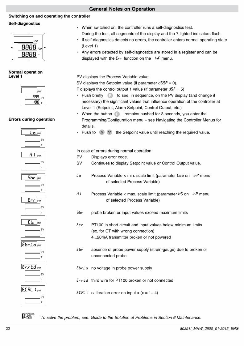
To solve the problem, see: Guide to the Solution of Problems in Section 6 Maintenance.
Switching on and operating the controllerSelf-diagnostics
8888 SV
F
PV
8888
Normal operationLevel 1
Errors during operation
SV
F
PVLo
SV
F
PVXi
SV
F
PVSbr
SV
F
PVErr
SV
F
PVEbr
SV
F
PV
399
400
SV
F
PVEbr.Lo
SV
F
PVEr.rtd
SV
F
PVE.(AL.1
• Whenswitchedon,thecontrollerrunsaself-diagnosticstest. During the test, all segments of the display and the 7 lighted indicators flash.• Ifself-diagnosticsdetectsnoerrors,thecontrollerentersnormaloperatingstate (Level 1)• Anyerrorsdetectedbyself-diagnosticsarestoredinaregisterandcanbe displayed with the ERR function on the INF menu.
PV displays the Process Variable value.SV displays the Setpoint value (if parameter dS.SP = 0).F displays the control output 1 value (if parameter dS.F = 5)• Pushbrieflytosee,insequence,onthePVdisplay(andchangeif necessary) the significant values that influence operation of the controller at Level 1 (Setpoint, Alarm Setpoint, Control Output, etc.)• Whenthebuttonremainspushedfor3seconds,youenterthe Programming/Configuration menu – see Navigating the Controller Menus for details.• PushtotheSetpointvalueuntilreachingtherequiredvalue.
In case of errors during normal operation:PV Displays error code.SV Continues to display Setpoint value or Control Output value.
LO Process Variable < min. scale limit (parameter LOS on INP menu of selected Process Variable)
KI Process Variable < max. scale limit (parameter K’S on INP menu of selected Process Variable)
SBR probe broken or input values exceed maximum limits
ERR PT100 in short circuit and input values below minimum limits (ex. for CT with wrong connection) 4...20mA transmitter broken or not powered
EbR absence of probe power supply (strain-gauge) due to broken or unconnected probe
Ebr.Lo no voltage in probe power supply
Er.rtd third wire for PT100 broken or not connected
E.(AL.1 calibration error on input x (x = 1...4)
22 80291I_MHW_2500_01-2015_ENG

Display level 1
SV
F
PV
SV
F
PV
SV
F
PV
SV
F
PV
SV
F
PV
SV
F
PV
SV
F
PV
SV
F
PV
Maths function A
SV
F
PV
Maths function b
Menu
SP.1
SP.2
In.1
In.3
In.2
In.4
F1n.A
Fin.b
Local Setpoint[LoSP ... xiSP]
Setpoint 1[LoSP ... xiSP]
Setpoint 2[LoSP ... xiSP]
Input 1
Input 2
Input 3
Input 4
SV
F
PV
SET.P
SV
F
PV Coefficient C1.A Maths function A (in Func A = 7)
(1.a
SV
F
PV Coefficient C1.b Maths function b(in Func b = 7)
(1.b
Navigating the Controller MenusKeep this button pushed to scroll the menus in succession; release when the required menu appears.Push to access the parameters of the selected menu.Keep + pushed to return immediately to level 1.
2380291I_MHW_2500_01-2015_ENG

Insignificant configuration parameters and menus are NOT displayed.
The display returns to level 1 if the keys are not pressed within about 15 seconds
SV
F
PV
SV
F
PV
SV
F
PV
Control outputs value[-100.0 ... 100.0] %
SV
F
PV
AL.1
AL.2
AL.3
0vt.P
Alarm setpoint 1[Lo.AL ... xi.AL] if absolute[-9999 ... +9999] if relative
Alarm setpoint 2[Lo.AL ... xi.AL] if absolute[-9999 ... +9999] if relative
Alarm setpoint 3[Lo.AL ... xi.AL] if absolute[-9999 ... +9999] if relative
SV
F
PV Number identifying active PID parameters group(only if n.Pid > 1)A.Pid
Control 2 output value (*)SV
F
PV
(.out.2
SV
F
PV
(.out.1
Control 1 output value (*)
SV
F
PV
AL.4
Alarm setpoint 4[Lo.AL ... xi.AL] if absolute[-9999 ... +9999] if relative
SV
F
PV
SV
F
PV
SV
F
PV
AL.5
AL.6
AL.7
Alarm setpoint 5[Lo.AL ... xi.AL] if absolute[-9999 ... +9999] if relative
Alarm setpoint 6[Lo.AL ... xi.AL] if absolute[-9999 ... +9999] if relative
Alarm setpoint 7[Lo.AL ... xi.AL] if absolute[-9999 ... +9999] if relative
SV
F
PV
AL.8
Alarm setpoint 8[Lo.AL ... xi.AL] if absolute[-9999 ... +9999] if relative
SV
F
PV
AL.9
Alarm setpoint 9[Lo.AL ... xi.AL] if absolute[-9999 ... +9999] if relative
SV
F
PV
AL.10
Alarm setpoint 10[Lo.AL ... xi.AL] if absolute[-9999 ... +9999] if relative
(*) the automatic return to level 1 is disabled
24 80291I_MHW_2500_01-2015_ENG

Menu
Display information
OK
Jumper S9 on CPU board
(see section 6 - maintenance)S9 ON ?NO
Configuration of control parameters
Configuration of function modes
Serial Communication
Configurationof Input 1
Configurationof Input 3
Protection Code
HardwareConfiguration
InputLinearization
UserCalibration
SV
F
PV
SV
F
PV
SV
F
PV
SV
F
PV
SV
F
PV
SV
F
PV
SV
F
PV
SV
F
PV
SV
F
PV
Configurationof Input 2SV
F
PV
InF
(fG.Pd
(fG
SEr
InP.1
InP.2
Configurationof Input 4
InP.3
InP.4
Configurationof trip points
Configurationof outputs
ALL
0vt
OKPAS=99 ?
NO - set 99 without pushing- Push once to access PRO parameter- Keep pushed to access the next menu
Password SV
F
PV
PAS
Pro
xrd
U.(A
Lin
PAS=30 Configuration 0(default)
YES
PAS=31 Configuration 1YES
PAS=32 Configuration 2YES
2580291I_MHW_2500_01-2015_ENG

4 • CONFIGURATION / PROGRAMMINGThis section contains the instructions needed to confi-gure the 2500 Controller as required.
To provide optimum functioning in its intended application, the 2500 Controller’s control parameters have to be correctly con-figured and programmed. The flexibility and high performance of these instruments is based on numerous parameters that the user can program directly via the control panel buttons, or transfer from PC in the form of configuration file via the optio-nal digital communication interface.
ConfigurationAccess to all configuration / programming menus and to all parameters available for the 2500 Controllers means that the Controller can be configured extremely precisely to satisfy any applicative requirement.
The correct setting of configuration parameters assumes expertise in control problems and techni-ques. Therefore, do not change these parameters if you are not fully aware of the consequences that may
derive from improper setting.
To prevent harm to persons or property, the user is responsible for checking that all parameters are correctly set before the Controller is put into ope-ration.
If you have any doubts or need any explanation, consult the website www.gefran.com or call Gefran Customer Care.
The following pages describe each of the Controller’s menus and, for each parameter, provide a concise description of its function, its default value (if any), and its range of settable values.Example: Parameter IT.1 on (FG menu
(default value)
Integral time of Pid 1 group [0.0 ... 99.99] min
Supplemental Notes for Consultation of Configuration/Programming PagesWhen setting a few highly complex parameters, you need to consult certain tables or detailed notes.These tables or notes are found on the right side of the page for the parameter in question.
Applicative Notes Detailed explanations of certain operating modes or special techniques developed by Gefran in its years of experience in the control field are provided at the end of
the Configuration/Programming Section, and are a valuable consulting tool for the user. References are made to these Applicative Notes, where necessary, in the configuration / programming flows.
Password: PASThe message PAS appears when scrolling the menus (button kept pusched), after the 0VT menu.Subsequent menus can be accessed only by setting the para-meter PAS = 99, then pushing .After setting the value 99, push and keep pushed to access subsequent menus.
Protection Code: PROThe PRO parameter lets you enable or disable the display and/or change of certain parameters.For details, see the description of the PRO parameter in the configuration flows.
Jumper S9 on CPU BoardThe absence of jumper S9 on the Controller’s CPU board blocks access to all menus when the instrument’s hardware configuration does not required any change of preset parame-ters.This jumper is inserted or removed in the factory, and normally does not need to be changed by the final user.
For more information, see section 6 - Maintenance.
SV
F
PV
It.1
26 80291I_MHW_2500_01-2015_ENG

*) by adding the following numbers to the value shown in the table, you can enable a series of supplemental functions: +16 with automatic switching to GO if IPV-SPI > 0,5% +32 with automatic switching to GO if IPV-SPI > 1% +64 with automatic switching to GO if IPV-SPI > 2% +128 with automatic switching to GO if IPV-SPI > 4%
**) For more information on the Self Tuning, Auto Tuning, Soft Start functions, see paragraph Notes on Operation.
InF InformationsThis menu lets you display the state of the controller
SV
F
PV
InF
Software release
Instrument code
0 no error 1 Lo 2 Hi 3 Err 4 Sbr 5 Ebr 6 Ebr.Lo 7 Er.rtd 8 Er.CAL
Error code IN 1
SV
F
PV
UPd
SV
F
PV
(od
SV
F
PV
Err.1
Error code IN 2SV
F
PV
Err.2
Error code IN 3SV
F
PV
Err.3
Error code IN 4SV
F
PV
Err.4
See: General notes on operation
(FG PID ConfigurationThis menu lets you configure the various control parameters.
Enable Self Tuning, Auto Tuning, Soft Start (**)
S.tun Continuous Selftuning Softstart Autotuning 0 NO NO NO 1 YES NO NO 2 NO YES NO 3 YES YES NO 4 NO NO YES 5 YES NO YES 6 - - - 7 - - - S.tun One-shot Selftuning Softstart Autotuning 8* WAIT NO NO 9 GO NO NO 10* WAIT YES NO 11 GO YES NO 12* WAIT NO YES 13 GO NO YES
SV
F
PV
SV
F
PV
S.tv
(fG.Pd
A
Error code Fin ASV
F
PV
Err.5
Error code Fin bSV
F
PV
Err.6
Positioning decimal point Fin.A(read only)
Positioning decimal point Fin.b(read only)
MIN scale limit Fin.A(read only)
MIN scale limit Fin.b(read only)
MAX scale limit Fin.A(read only)
MAX scale limit Fin.b(read only)
SV
F
PV
dP5.5
SV
F
PV
dP5.6
SV
F
PV
lo5.5
SV
F
PV
lo5.6
SV
F
PV
xi5.5
SV
F
PV
xi5.6
Baudrate Profibus DP 0 12.00 Mbit/s 1 6.00 Mbit/s 2 3.00 Mbit/s 3 1.50 Mbit/s 4 500.00 Kbit/s 5 187.50 Kbit/s 6 93.75 Kbit/s 7 46.45 Kbit/s 8 19.20 Kbit/s 9 9.60 Kbit/s
SV
F
PV
SV
F
PV
SV
F
PV
fieldbus software version
fieldbus instrument code (read only)
fieldbus Baudrate (read only)
UPd.F
(od.F
bAv.F
2780291I_MHW_2500_01-2015_ENG
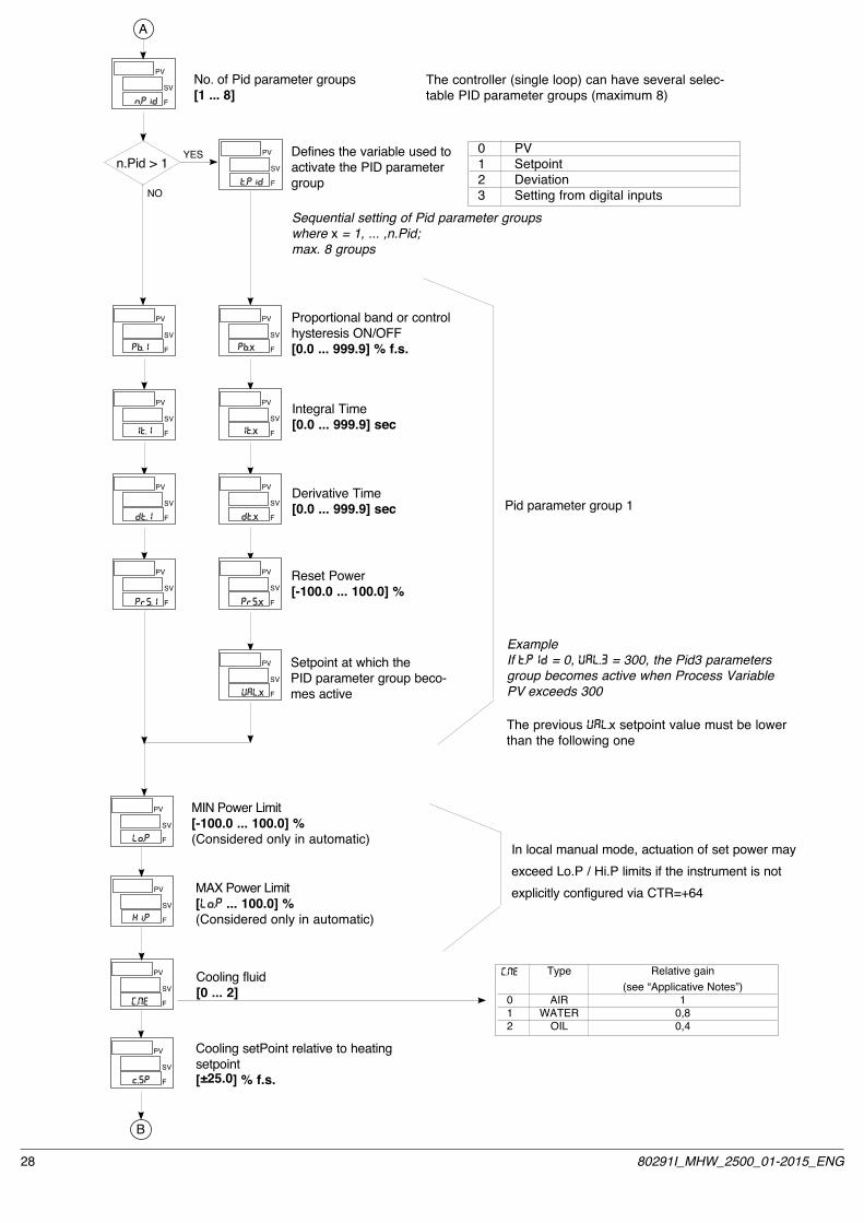
MIN Power Limit[-100.0 ... 100.0] %(Considered only in automatic)
MAX Power Limit[Lo.P ... 100.0] %(Considered only in automatic)
Cooling fluid [0 ... 2]
Cooling setPoint relative to heating setpoint [ ±25.0] % f.s.
SV
F
PV
SV
F
PV
SV
F
PV
SV
F
PV
SV
F
PV Defines the variable used to activate the PID parameter group
SV
F
PV
SV
F
PV
SV
F
PV
SV
F
PV
SV
F
PV
Sequential setting of Pid parameter groupswhere x = 1, ... ,n.Pid;max. 8 groups
Proportional band or control hysteresis ON/OFF[0.0 ... 999.9] % f.s.
Integral Time[0.0 ... 999.9] sec
Derivative Time[0.0 ... 999.9] sec
Reset Power[-100.0 ... 100.0] %
Setpoint at which the PID parameter group beco-mes active
Pb.x
It.x
dt.x
PrS.x
UAL.x
t.Pid
ExampleIf t.Pid = 0, UAL.3 = 300, the Pid3 parameters group becomes active when Process Variable PV exceeds 300
Pid parameter group 1
Lo.P
xI.P
(.MEi
Type Relative gain (see “Applicative Notes”) 0 AIR 1 1 WATER 0,8 2 OIL 0,4
(.MEi
c.SP
SV
F
PV
SV
F
PV
SV
F
PV
SV
F
PV
Pb.1
It.1
dt.1
PrS.1
n.Pid > 1YES
NO
B
No. of Pid parameter groups[1 ... 8]SV
F
PV
n.Pid
A
0 PV 1 Setpoint 2 Deviation 3 Setting from digital inputs
The controller (single loop) can have several selec-table PID parameter groups (maximum 8)
The previous UAL.x setpoint value must be lower than the following one
In local manual mode, actuation of set power may exceed Lo.P / Hi.P limits if the instrument is not explicitly configured via CTR=+64
28 80291I_MHW_2500_01-2015_ENG
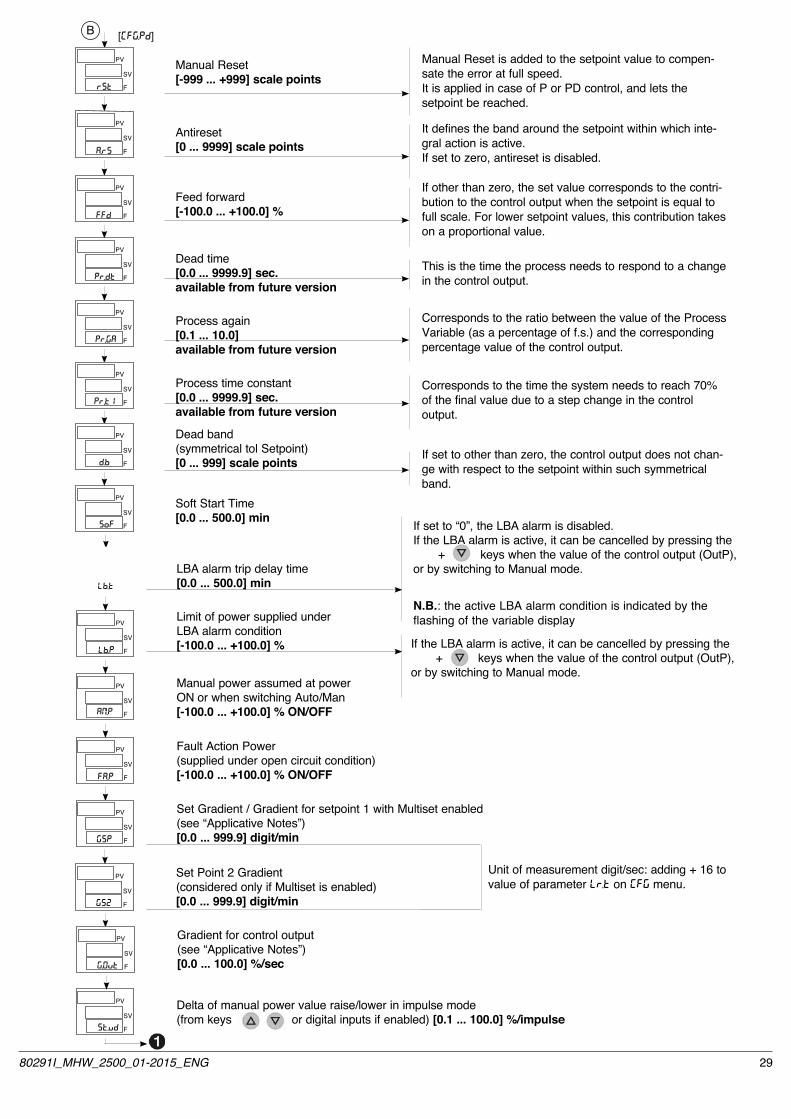
Limit of power supplied under LBA alarm condition[-100.0 ... +100.0] %
Manual power assumed at power ON or when switching Auto/Man[-100.0 ... +100.0] % ON/OFF
Fault Action Power(supplied under open circuit condition)[-100.0 ... +100.0] % ON/OFF
Delta of manual power value raise/lower in impulse mode(from keys or digital inputs if enabled) [0.1 ... 100.0] %/impulse
If the LBA alarm is active, it can be cancelled by pressing the + keys when the value of the control output (OutP), or by switching to Manual mode.
SV
F
PV
SV
F
PV
SV
F
PV
SV
F
PV
SV
F
PV
LBA alarm trip delay time[0.0 ... 500.0] min
If set to “0”, the LBA alarm is disabled.If the LBA alarm is active, it can be cancelled by pressing the + keys when the value of the control output (OutP), or by switching to Manual mode.
B [(FG.Pd]
Dead time[0.0 ... 9999.9] sec.available from future version
Process again[0.1 ... 10.0]available from future version
Process time constant[0.0 ... 9999.9] sec.available from future version
Dead band(symmetrical tol Setpoint)[0 ... 999] scale points
Manual Reset[-999 ... +999] scale points
Antireset[0 ... 9999] scale points
Feed forward[-100.0 ... +100.0] %
Soft Start Time[0.0 ... 500.0] min
SV
F
PV
SV
F
PV
SV
F
PV
SV
F
PV
SV
F
PV
SV
F
PV
SV
F
PV
SV
F
PV
rSt
A.rS
FFd
Pr,dt
Pr,GA
Pr,t1
d.b
SoF
Lb.t
Lb.P
AM.Pi
FA.P
GSP
St.vd
SV
F
PV
GS2
Gradient for control output(see “Applicative Notes”)[0.0 ... 100.0] %/sec
SV
F
PV
G.0vt
Manual Reset is added to the setpoint value to compen-sate the error at full speed.It is applied in case of P or PD control, and lets the setpoint be reached.
It defines the band around the setpoint within which inte-gral action is active.If set to zero, antireset is disabled.
If other than zero, the set value corresponds to the contri-bution to the control output when the setpoint is equal to full scale. For lower setpoint values, this contribution takes on a proportional value.
Corresponds to the ratio between the value of the Process Variable (as a percentage of f.s.) and the corresponding percentage value of the control output.
Corresponds to the time the system needs to reach 70% of the final value due to a step change in the control output.
If set to other than zero, the control output does not chan-ge with respect to the setpoint within such symmetrical band.
This is the time the process needs to respond to a change in the control output.
Set Gradient / Gradient for setpoint 1 with Multiset enabled(see “Applicative Notes”)[0.0 ... 999.9] digit/min
Unit of measurement digit/sec: adding + 16 to value of parameter Lr.t on (FG menu.
Set Point 2 Gradient(considered only if Multiset is enabled)[0.0 ... 999.9] digit/min
N.B.: the active LBA alarm condition is indicated by the flashing of the variable display
2980291I_MHW_2500_01-2015_ENG
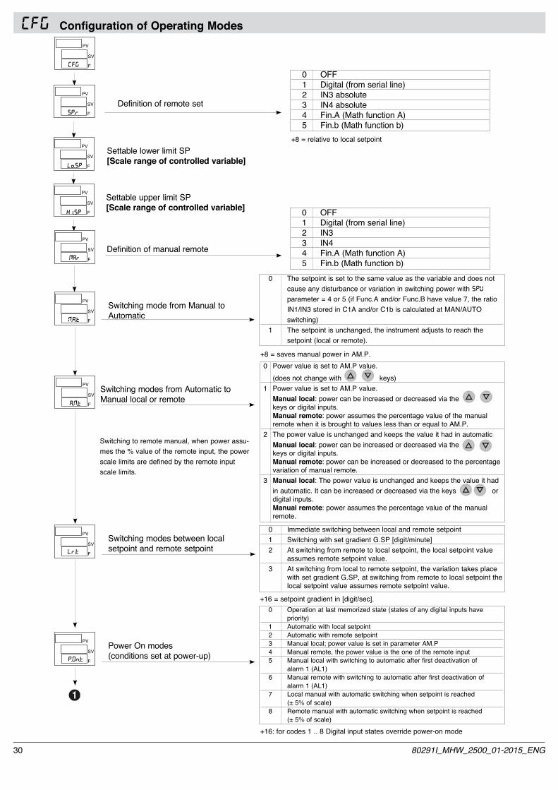
(FG Configuration of Operating Modes
Switching mode from Manual to Automatic
0 The setpoint is set to the same value as the variable and does not cause any disturbance or variation in switching power with SPU parameter = 4 or 5 (if Func.A and/or Func.B have value 7, the ratio IN1/IN3 stored in C1A and/or C1b is calculated at MAN/AUTO switching) 1 The setpoint is unchanged, the instrument adjusts to reach the setpoint (local or remote).
SV
F
PV
Switching modes from Automatic to Manual local or remote
0 Power value is set to AM.P value. (does not change with keys) 1 Power value is set to AM.P value. Manual local: power can be increased or decreased via the keys or digital inputs. Manual remote: power assumes the percentage value of the manual remote when it is brought to values less than or equal to AM.P. 2 The power value is unchanged and keeps the value it had in automatic Manual local: power can be increased or decreased via the keys or digital inputs. Manual remote: power can be increased or decreased to the percentage variation of manual remote. 3 Manual local: The power value is unchanged and keeps the value it had in automatic. It can be increased or decreased via the keys or digital inputs. Manual remote: power assumes the percentage value of the manual remote.
SV
F
PV
Switching modes between localsetpoint and remote setpoint
0 Immediate switching between local and remote setpoint 1 Switching with set gradient G.SP [digit/minute] 2 At switching from remote to local setpoint, the local setpoint value assumes remote setpoint value. 3 At switching from local to remote setpoint, the variation takes place with set gradient G.SP, at switching from remote to local setpoint the local setpoint value assumes remote setpoint value.
SV
F
PV
+16 = setpoint gradient in [digit/sec].
Power On modes(conditions set at power-up)
0 Operation at last memorized state (states of any digital inputs have priority) 1 Automatic with local setpoint 2 Automatic with remote setpoint 3 Manual local; power value is set in parameter AM.P 4 Manual remote, the power value is the one of the remote input 5 Manual local with switching to automatic after first deactivation of alarm 1 (AL1) 6 Manual remote with switching to automatic after first deactivation of alarm 1 (AL1) 7 Local manual with automatic switching when setpoint is reached (± 5% of scale) 8 Remote manual with automatic switching when setpoint is reached (± 5% of scale)
SV
F
PV
SV
F
PV
Definition of remote set
0 OFF 1 Digital (from serial line) 2 IN3 absolute 3 IN4 absolute 4 Fin.A (Math function A) 5 Fin.b (Math function b)
SV
F
PV Settable lower limit SP[Scale range of controlled variable]
SV
F
PV Settable upper limit SP[Scale range of controlled variable]
SP.r
Lo.SP
xi.SP
M.A.t1
A.M.t1
L.r.t
P.0n.t
+8 = saves manual power in AM.P.
SV
F
PV
Definition of manual remoteMAr1
0 OFF 1 Digital (from serial line) 2 IN3 3 IN4 4 Fin.A (Math function A) 5 Fin.b (Math function b)
SV
F
PV
(FG
+8 = relative to local setpoint
Switching to remote manual, when power assu-mes the % value of the remote input, the power scale limits are defined by the remote input scale limits.
+16: for codes 1 .. 8 Digital input states override power-on mode
30 80291I_MHW_2500_01-2015_ENG

SEr Serial CommunicationThis menu lets you configure the various parameters that control serial communication between controller and supervisor.
Instrument Identification Code[0 ... 247]
Select Parity
Select Baudrate
Parity 0 No Parity 1 Odd 2 Even
Baudrate 0 1200 bit/s 1 2400 bit/s 2 4800 bit/s 3 9600 bit/s 4 19200 bit/s 5 38400 bit/s 6 57600 bit/s 7 115200 bit/s
SV
F
PV
SV
F
PV
SV
F
PV
SV
F
PV
SEr
(od
bAv
PAr
3180291I_MHW_2500_01-2015_ENG

InP .1 Setting Input 1This menu lets you configure parameters for the input 1 signals
Probe type, signal, enable custom linearization, and main input scale.
Probe type Scale limits0 Input disabled 1 TC J °C 0/10002 TC J °F 32/18323 TC K °C 0/13004 TC K °F 32/23725 TC R °C 0/17506 TC R °F 32/31827 TC S °C 0/17508 TC S °F 32/31829 TC T °C -200/40010 TC T °F -328/75211 PT100 °C -200/85012 PT100 °F -328/1562
Probe type Scale limits13 Potentiometer≥100Ω -19999/99999 with 2.5V power supply14 Strain gauge -19999/99999 positive polarization sensitivity: 1.5 ... 4mV/V15 Strain gauge -19999/99999 symmetrical polarization sensitivity: 1.5 ... 4mV/V16 60mV -19999/9999917 ±60mV -19999/9999918 100mV -19999/9999919 ±100mV -19999/9999920 1V -19999/9999921 ±1V -19999/9999922 5V -19999/9999923 ±5V -19999/9999924 10V -19999/9999925 ±10V -19999/9999926 0...20 mA -19999/9999927 4...20 mA -19999/9999928 Strain-gauge positive -19999/99999 polarization calibrated 40mV 29 Strain-gauge symmetrical -19999/99999 polarization calibrated 40mV30 Strain-gauge positive -19999/99999 polarization calibrated 60mV 31 Strain-gauge symmetrical -19999/99999 polarization calibrated 60mV
SV
F
PV
SV
F
PV
Input 1 Digital Filter[0.00 ... 20.00] secSV
F
PV
InP.1
tyP.1
F1t.1
SV
F
PV Decimal Point Position for ScaleInput 1
dPS.1
SV
F
PV
MIN Scale Limit Input 1
SV
F
PV
MAX Scale Limit Input 1
LoS.1
x1S.1
SV
F
PV
Offset Correction Input 1[-999 ... +999] scale points0FS.1
SV
F
PV
Offset Input 1[-9.999 ... +9.999] mVSG0F.1
SV
F
PV
Sensitivity Input 1[-0.000 ... +9.999] mV/VSGSE.1
Only for probe type 28, 29, 30, 31
Note- For input type 27 (4...20mA), a current below 2mA causes the Err and activates the assigned relay state specified with parame-ter -rEL.- The type 28, 29, 30, 31 input can be used without having to cali-brate the probe. Simply enter the Offset and Sensitivity data reque-sted in configuration (ex.: 0.193mV; 1.985mV/V).- For types 28, 29 Maximum sensitivity is 4mV/V with 10V power supply.- For types 30, 31 Maximum sensitivity is 6mV/V with 10V power supply.
If set to “0” the average filter is excluded on the sampled value
+32 with custom linearization+64 only for cold junction compensation thermocouples
Size 0 xxxxx 1 xxxx.x 2 xxx.xx (*) 3 xx.xxx (*) 4 x.xxxx (*)
(*) Not available for TC, RTD probes
+8 disables the Lo and x1 messages for linear inputs only+16 disables the Ebr message+32 for differential linear inputs probe type 16...25+64 disables the E.CAL.1 message
Min...Max value assigned to input selected with parameter TYP1[LoS.1 must be always < than xiS.1]
32 80291I_MHW_2500_01-2015_ENG
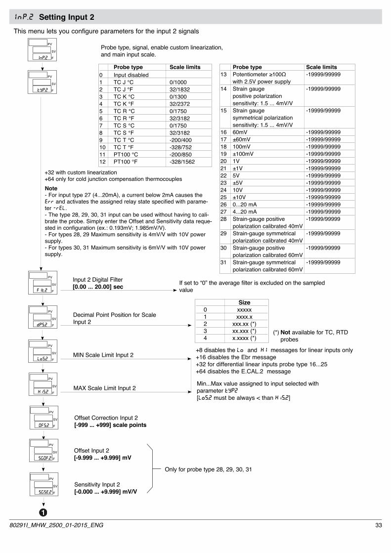
InP .2 Setting Input 2 This menu lets you configure parameters for the input 2 signals
Probe type, signal, enable custom linearization, and main input scale.
Probe type Scale limits0 Input disabled 1 TC J °C 0/10002 TC J °F 32/18323 TC K °C 0/13004 TC K °F 32/23725 TC R °C 0/17506 TC R °F 32/31827 TC S °C 0/17508 TC S °F 32/31829 TC T °C -200/40010 TC T °F -328/75211 PT100 °C -200/85012 PT100 °F -328/1562
Probe type Scale limits13 Potentiometer≥100Ω -19999/99999 with 2.5V power supply14 Strain gauge -19999/99999 positive polarization sensitivity: 1.5 ... 4mV/V15 Strain gauge -19999/99999 symmetrical polarization sensitivity: 1.5 ... 4mV/V16 60mV -19999/9999917 ±60mV -19999/9999918 100mV -19999/9999919 ±100mV -19999/9999920 1V -19999/9999921 ±1V -19999/9999922 5V -19999/9999923 ±5V -19999/9999924 10V -19999/9999925 ±10V -19999/9999926 0...20 mA -19999/9999927 4...20 mA -19999/9999928 Strain-gauge positive -19999/99999 polarization calibrated 40mV 29 Strain-gauge symmetrical -19999/99999 polarization calibrated 40mV30 Strain-gauge positive -19999/99999 polarization calibrated 60mV 31 Strain-gauge symmetrical -19999/99999 polarization calibrated 60mV
SV
F
PV
SV
F
PV
Input 2 Digital Filter[0.00 ... 20.00] secSV
F
PV
InP.2
tyP.2
F1t.2
SV
F
PV Decimal Point Position for ScaleInput 2
dPS.2
SV
F
PV
MIN Scale Limit Input 2
SV
F
PV
MAX Scale Limit Input 2
LoS.2
x1S.2
SV
F
PV
Offset Correction Input 2[-999 ... +999] scale points0FS.2
SV
F
PV
Offset Input 2[-9.999 ... +9.999] mVSG0F.2
SV
F
PV
Sensitivity Input 2[-0.000 ... +9.999] mV/VSGSE.2
Only for probe type 28, 29, 30, 31
Note- For input type 27 (4...20mA), a current below 2mA causes the Err and activates the assigned relay state specified with parame-ter -rEL.- The type 28, 29, 30, 31 input can be used without having to cali-brate the probe. Simply enter the Offset and Sensitivity data reque-sted in configuration (ex.: 0.193mV; 1.985mV/V).- For types 28, 29 Maximum sensitivity is 4mV/V with 10V power supply.- For types 30, 31 Maximum sensitivity is 6mV/V with 10V power supply.
If set to “0” the average filter is excluded on the sampled value
+32 with custom linearization+64 only for cold junction compensation thermocouples
Size 0 xxxxx 1 xxxx.x 2 xxx.xx (*) 3 xx.xxx (*) 4 x.xxxx (*)
(*) Not available for TC, RTD probes
+8 disables the Lo and x1 messages for linear inputs only+16 disables the Ebr message+32 for differential linear inputs probe type 16...25+64 disables the E.CAL.2 message
Min...Max value assigned to input selected with parameter TYP2[LoS.2 must be always < than xiS.2]
3380291I_MHW_2500_01-2015_ENG

InP .3 Setting Input 3
This menu lets you configure parameters for the input 3 signals.
Probe type, signal, enable custom linearization, and main input scale
SV
F
PV
SV
F
PV
Input 3 Digital Filter[0.00 ... 20.00] secSV
F
PV
If set to “0” the average filter is excluded on the sampled value
InP.3
tyP.3
F1t.3
SV
F
PV Decimal Point Position for ScaleInput 3
Size 0 xxxxx 1 xxxx.x 2 xxx.xx 3 xx.xxx 4 x.xxxx
dPS..3
SV
F
PV
MIN Scale Limit Input 3
SV
F
PV
MAX Scale Limit Input 3
LoS.3
x1S.3
SV
F
PV
Offset Correction Input 3[-999 ... +999] scale points0FS.3
Probe type Scale limits 0 Input disabled 1 0...10V -19999/99999 2 0...20mA -19999/99999 3 4...20mA -19999/99999 4 potentiometer -19999/99999
+32 enable custom linearization
+8 disables the Lo and x1 messages+64 disables the E.CAL.3 message
Min...Max value assigned to the input selected with parameter TYP3[LoS.3 must be always < than xiS.3]
34 80291I_MHW_2500_01-2015_ENG
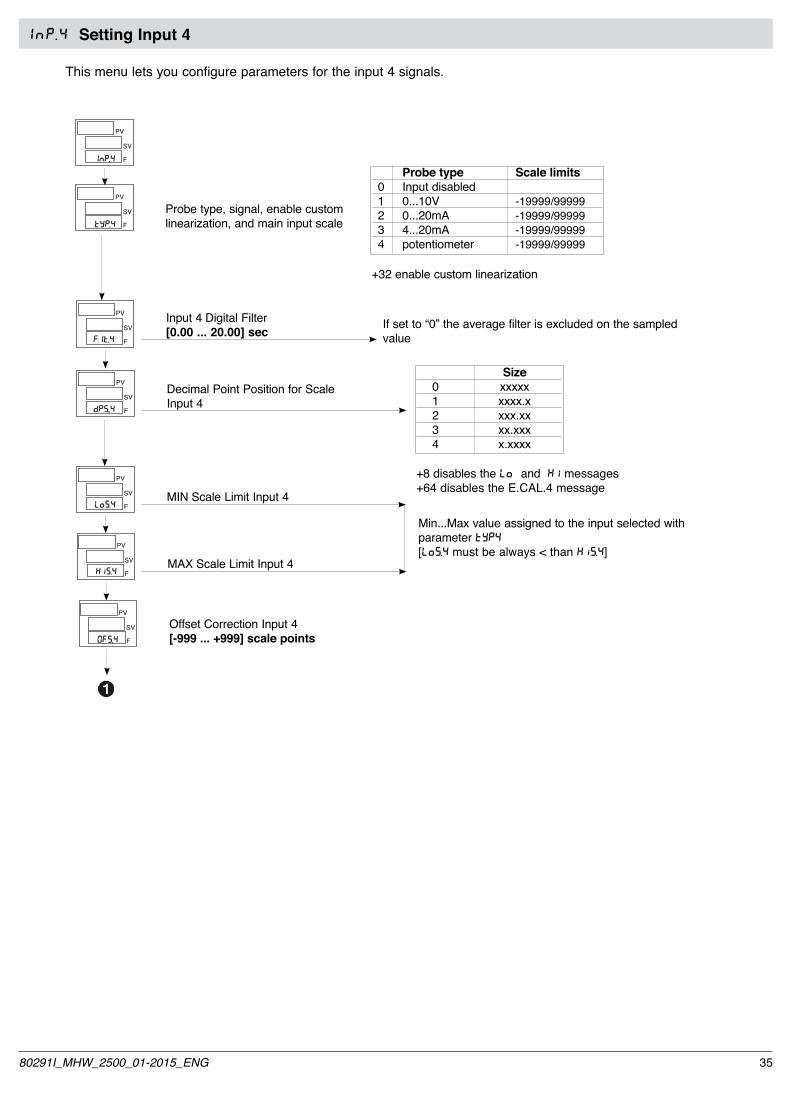
InP .4 Setting Input 4
This menu lets you configure parameters for the input 4 signals.
Probe type, signal, enable custom linearization, and main input scale
SV
F
PV
SV
F
PV
Input 4 Digital Filter[0.00 ... 20.00] secSV
F
PV
If set to “0” the average filter is excluded on the sampled value
InP.4
tyP.4
F1t.4
SV
F
PV Decimal Point Position for ScaleInput 4
Size 0 xxxxx 1 xxxx.x 2 xxx.xx 3 xx.xxx 4 x.xxxx
dPS..4
SV
F
PV
MIN Scale Limit Input 4
SV
F
PV
MAX Scale Limit Input 4
LoS.4
x1S.4
SV
F
PV
Offset Correction Input 4[-999 ... +999] scale points0FS.4
Probe type Scale limits 0 Input disabled 1 0...10V -19999/99999 2 0...20mA -19999/99999 3 4...20mA -19999/99999 4 potentiometer -19999/99999
+32 enable custom linearization
+8 disables the Lo and x1 messages+64 disables the E.CAL.4 message
Min...Max value assigned to the input selected with parameter TYP4[LoS.4 must be always < than xiS.4]
3580291I_MHW_2500_01-2015_ENG

ALL Setting AlarmsThis menu lets you configure parameters for the alarm functions.
Reference quantity 0 IN1 1 IN2 2 IN3 3 IN4 4 Fin.A (math function A) 5 Fin.b (math function b) 6 PV - Process Variable (input selected in SPU) 7 SSP - Active Setpoint 8 SP - Local Setpoint 9 DEV - Deviation (PV - SSP) (only for absolute type) 10 CO1 (control output 1) (scale range like the power 0 ÷ 100.0 % and 0 ÷ -100.0 %) 11 CO2 (control output 2) (scale range like the power 0 ÷ 100.0 % and 0 ÷ -100.0 %) 12 Value acquired from serial line 13 Max peak input 1 14 Min peak input 1 15 Input 1 peak - peak 16 Max peak input 2 17 Min peak input 2 18 Input 2 peak - peak
Select reference quantitiesAlarm n
Alarm n type
By adding the following numbers to the value shown in the table, you can enable a series of supplemental functions:+8: disable power-on until first trip point.+16: enable memory latch.+32: change color of PV display in case of active alarm+256: change color of PV display if limit is exceeded (only for alarms with timed delay)+512: enable string if alarm is active+1024:enable string if limit is exceeded (only for alarms with timed delay)
N.B.:For deviation alarms, reference quantities must have the same decimal resolution
Hysteresis for alarm n[±9999] scale points
Alarm n activation time[0 ... 999] min/sec/msec(see bt.n parameter)
Time base for Alarm n SV activation time
0 msec 1 sec 2 min
A
n. alarmn = 1
Character A alarm n string[0 ... 255]
Character B alarm n string[0 ... 255]
Character C alarm n string[0 ... 255]
Character D alarm n string[0 ... 255]
Character E alarm n string[0 ... 255]
n = n + 1
n > AL.n
YES
NO
Direct Normal (maximum) Absolute/Relative Symmetrical Inverse (minimum) to active Setpoint (window) 0 Direct Absolute Normal 1 Inverse Absolute Normal 2 Direct Relative Normal 3 Inverse Relative Normal 4 Direct Absolute Symmetrical 5 Inverse Absolute Symmetrical 6 Direct Relative Symmetrical 7 Inverse Relative Symmetrical
SV
F
PV
ALL
SV
F
PV
Ar.n
SV
F
PV
At.n
SV
F
PV
xy.n
SV
F
PV
rA.n
SV
F
PV
bt.n
SV
F
PV
sdA.n
SV
F
PV
sdb.n
SV
F
PV
sd(.n
SV
F
PV
sdd.n
SV
F
PV
sde.n
36 80291I_MHW_2500_01-2015_ENG

MIN limit alarm setpoint[-19999 ... 99999]
MAX limit alarm setpoint[-19999 ... 99999]
A
Fault Action (definition of alarm state in case of broken probe Err, Sbr, Ebr)Active only for the alarm related to the fault input
Alarm 1 Alarm 2 Alarm 3 0 OFF OFF OFF 1 ON OFF OFF 2 OFF ON OFF 3 ON ON OFF 4 OFF OFF ON 5 ON OFF ON 6 OFF ON ON 7 ON ON ON
[ALL]
State of alarms 4...10 = OFF+16 for state of alarms 4...10 = ON
SV
F
PV
Lo.AL
SV
F
PV
xi.AL
SV
F
PV
rEL
3780291I_MHW_2500_01-2015_ENG
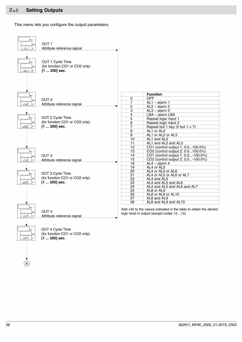
0vt Setting Outputs
This menu lets you configure the output parameters.
OUT 1 Cycle Time(for function CO1 or CO2 only)[1 ... 200] sec.
OUT 1Attribute reference signal
SV
F
PV
SV
F
PV
RL.1
Function 0 OFF 1 AL1 – alarm 1 2 AL2 – alarm 2 3 AL3 – alarm 3 4 LBA – alarm LBA 5 Repeat logic input 1 6 Repeat logic input 2 7 Repeat but 1 key (if but 1 = 7) 8 AL1 or AL2 9 AL1 or AL2 or AL3 10 AL1 and AL2 11 AL1 and AL2 and AL3 12 CO1 (control output 1, 0.0...100.0%) 13 CO2 (control output 2, 0.0...100.0%) 14 CO1 (control output 1, 0.0...-100.0%) 15 CO2 (control output 2, 0.0...-100.0%) 18 AL4 – alarm 4 19 AL4 or AL5 20 AL4 or AL5 or AL6 21 AL4 or AL5 or AL6 or AL7 22 AL4 and AL5 23 AL4 and AL5 and AL6 24 AL4 and AL5 and AL6 and AL7 25 AL8 or AL9 26 AL8 or AL9 or AL10 27 AL8 and AL9 28 AL8 and AL9 and AL10
Add +32 to the values indicated in the table to obtain the denied logic level in output (except codes 12 ...15)
OUT 2 Cycle Time(for function CO1 or CO2 only)[1 ... 200] sec.
OUT 2Attribute reference signal
SV
F
PV
SV
F
PV
RL.2
OUT 3 Cycle Time(for function CO1 or CO2 only)[1 ... 200] sec.
OUT 3Attribute reference signal
SV
F
PV
SV
F
PV
RL.3
OUT 4 Cycle Time(for function CO1 or CO2 only)[1 ... 200] sec.
OUT 4Attribute reference signal
SV
F
PV
SV
F
PV
RL.4
ct.1
ct.2
ct.3
ct.4
A
38 80291I_MHW_2500_01-2015_ENG

A [0vt]
OUT 5Attribute reference signal
SV
F
PV
RL.5
Function 0 OFF 1 AL1 – alarm 1 2 AL2 – alarm 2 3 AL3 – alarm 3 4 LBA – alarm LBA 5 Repeat logic input 1 6 Repeat logic input 2 7 Repeat but 1 key 8 AL1 or AL2 9 AL1 or AL2 or AL3 10 AL1 and AL2 11 AL1 and AL2 and AL3 18 AL4 – alarm 4 19 AL4 or AL5 20 AL4 or AL5 or AL6 21 AL4 or AL5 or AL6 or AL7 22 AL4 and AL5 23 AL4 and AL5 and AL6 24 AL4 and AL5 and AL6 and AL7 25 AL8 or AL9 26 AL8 or AL9 or AL10 27 AL8 and AL9 28 AL8 and AL9 and AL10
Add +32 to the values indicated in the table to obtain the denied logic level in output
OUT 6Attribute reference signal
SV
F
PV
RL.6
OUT 7Attribute reference signal
SV
F
PV
RL.7
OUT 8Attribute reference signal
SV
F
PV
RL.8
SV
F
PV
OUT W Retransmission Output Type 0 Output disabled 1 0...10V 2 2...10V 3 0...20mA 4 4...20mA 5 ±10V
tyP.An
SV
F
PV Reference quantity 0 IN1 1 IN2 2 IN3 3 IN4 4 Fin.A (math function A) 5 Fin.b (math function b) 6 PV - Process Variable (input 1) 7 SSP - Active Setpoint 8 SP - Local Setpoint 9 DEV - Deviation (PV - SSP) 10 CO1 (control output 1) 11 CO2 (control output 2) 12 Value acquired from serial line 13 Input 1 maximum peak 14 Input 1 minimum peak 15 Input 1 peak-peak 16 Input 2 maximum peak 17 Input 2 minimum peak 18 Input 2 peak-peak 19 AL1 (limit) 20 AL2 (limit) 21 AL3 (limit)
riF.An
MIN analog repeat output scale[scale range -19999 ÷ +99999]
SV
F
PV
MAX analog repeat output scale[scale range -19999 ÷ +99999]
SV
F
PV
Lo.An
xi.An
SV
F
PV
Type Control Output 1 (CO1)
SV
F
PV
Type Control Output 2 (CO2)
0 Output disabled 1 0...10V (0.0 ... 100.0%) 2 2...10V (0.0 ... 100.0%) 3 0...20mA (0.0 ... 100.0%) 4 4...20mA (0.0 ... 100.0%) 5 0...10V (0.0 ... -100.0%) 6 2...10V (0.0 ... -100.0%) 7 0...20mA (0.0 ... -100.0%) 8 4...20mA (0.0 ... -100.0%) 9 -10...+10V (-100.0 ... +100.0%) 10 -10...+10V (+100.0 ... -100.0%)
Select probe power supply 0 2,5V for potentiometers 1 5V for strain gauge 2 10V for strain gauge
SV
F
PV
max. 200mA
tyP(.1
tyP(.2
ALS
Attribute reference signal OUT W
+8 reverse output
+32 only for riF.An = 0,1,2,3,4,5: output at max/min hardware (beyond calibration limits) for input at Hi/Lo+64 only for riF.An = 0,1,2,3,4,5: output at minimum if input is in Err, Sbr, Ebr condition
+16 reverse output
3980291I_MHW_2500_01-2015_ENG

PRO Protection CodeThis menu lets you enable/disable the display and/or change of certain parameters.(To access this menu, see the section “Using the controller menus”)
KRD Hardware ConfigurationThis menu lets you configure the hardware parameters. (To access this menu, see the section “Using the controller menus”).
Display Change 0 SEt.P, SP.1, SP.2, In.1, In.2 SEt.P, SP.1, SP.2, In.3,, In.4, Fin.A, Fin.B, AL.1, ....AL.10 AL.1, ....AL.10, [ovt.1, 0vt.P
[ovt.2
1 SEt.P, SP.1, SP.2, In.1, In.2 SEt.P, SP.1, SP.2 In.3,, In.4, Fin.A, Fin.B,
AL.1, ....AL.10, [ovt.1, 0vt.P
[ovt.2
2 SEt.P, SP.1, SP.2, In.1, In.2 In.3,, In.4, Fin.A, Fin.B,, [ovt.1,
0vt.P, [ovt.2
3 SEt.P, SP.1, SP.2, Fin.A, Fin.B, ,,0vt.P SEt.P, SP.1, SP.2,
by adding the following numbers to the value shown in the table, you can enable a series of supplemental functions:+4: disable menus InP.1, InP.2, InP.3, InP.4, ALL, 0vt+8: disable menus [FG.Pd, (fG, Ser+16: disable software “on – off” from keyboard+32: disable save tare
SV
F
PV
Pro
Enable MultiSet, process type line frequency and digital inputs
MultiSet Process type Line frequency (2SP) Fast to check pressure, flow rate. Slow to check temperature 0 Fast 50Hz 1 X Fast 50Hz 2 Slow 50Hz 3 X Slow 50Hz 4 Fast 60Hz 5 X Fast 60Hz 6 Slow 60Hz 7 X Slow 60Hz
SV
F
PV
SV
F
PV
Power limit type 1 (CO1)SV
F
PV
Power limit type 2 (CO2)SV
F
PV
xrd
xd.1
Control typeSV
F
PV Control type 0 PID heat / cool 1 ON – OFF heat 2 ON – OFF cool 3 ON – OFF heat / cool 4 PID heat + ON – OFF cool 5 ON – OFF heat + PID cool 6 PID heat + cool with Relative Gain (see “Notes on Operation”)
(tr
+16: to enable LBA alarm+32: high-resolution control calculation+64: local manual power within limits Lo.P/Hi.P+128: to avoid the integral power reset after setpoint variations (from version 1.44)
txL.1
txL.2
A
+8: digital inputs DIG1, DIG2, DIG3, DIG4 type NPN NB: digital input NPN is active with contact open, if you want reverse logic, set +64 in parameter diG.x+32: disable parameter rEL
0 max Hi.P, min Lo.P 1 max Hi.P, min Lo.P proportional to IN3 2 max Hi.P, min Lo.P proportional to IN4 3 max Hi.P, min = 0 4 max = 0, min Lo.P 5 max Hi.P proportional to IN3, min = 0 6 max = 0, min Lo.P proportional to IN4
40 80291I_MHW_2500_01-2015_ENG
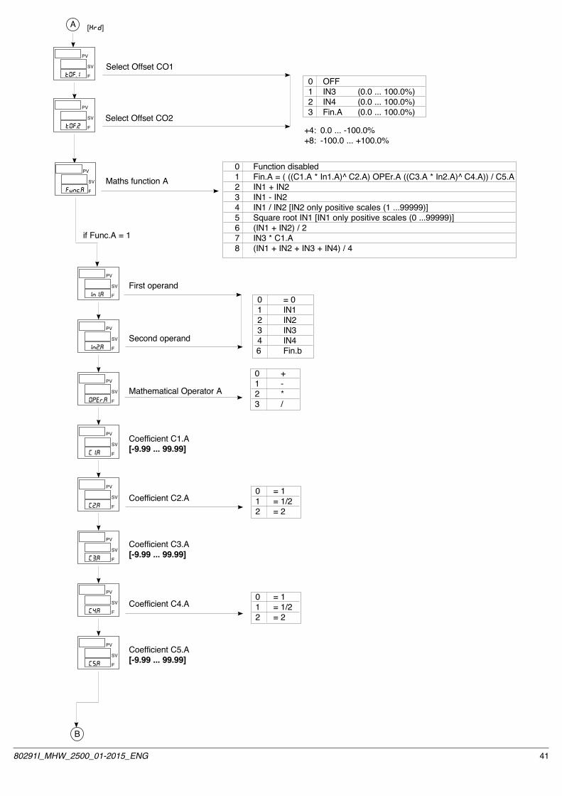
A [xrd]
Select Offset CO1SV
F
PV
Select Offset CO2SV
F
PV
t0F.1
t0F.2
SV
F
PV
Maths function A 0 Function disabled 1 Fin.A = ( ((C1.A * In1.A)^ C2.A) OPEr.A ((C3.A * In2.A)^ C4.A)) / C5.A 2 IN1 + IN2 3 IN1 - IN2 4 IN1 / IN2 [IN2 only positive scales (1 ...99999)] 5 Square root IN1 [IN1 only positive scales (0 ...99999)] 6 (IN1 + IN2) / 2 7 IN3 * C1.A 8 (IN1 + IN2 + IN3 + IN4) / 4
Fvnc.A
SV
F
PV
First operandIn1.A
if Func.A = 1
SV
F
PV
Second operandIn2.A
SV
F
PV
Mathematical Operator A0PEr.A
SV
F
PV Coefficient C1.A[-9.99 ... 99.99]
(1.A
SV
F
PV
Coefficient C2.A(2.A
SV
F
PV Coefficient C3.A[-9.99 ... 99.99]
(3.A
SV
F
PV
Coefficient C4.A(4.A
SV
F
PV Coefficient C5.A[-9.99 ... 99.99]
(5.A
0 = 0 1 IN1 2 IN2 3 IN3 4 IN4 6 Fin.b
0 + 1 - 2 * 3 /
B
0 = 1 1 = 1/2 2 = 2
0 = 1 1 = 1/2 2 = 2
0 OFF 1 IN3 (0.0 ... 100.0%) 2 IN4 (0.0 ... 100.0%) 3 Fin.A (0.0 ... 100.0%)
+4: 0.0 ... -100.0%+8: -100.0 ... +100.0%
4180291I_MHW_2500_01-2015_ENG

SV
F
PV
Maths function B
0 Function disabled 1 Fin.b = ( ((C1.B * In1.B)^ C2.B) OPEr.B ((C3.B * In2.B)^ C4.B)) / C5.B 2 IN1 + IN2 3 IN1 - IN2 4 IN1 / IN2 [IN2 only positive scales (1 ...99999)] 5 Square root IN1 [IN1 only positive scales (0 ...99999)] 6 (IN1 + IN2)/ 2 7 IN3 * C1.B 8 (IN1 + IN2 + IN3 + IN4) / 4
Fvnc.b
SV
F
PV
First operandIn1.b
if Func.b = 1
SV
F
PV
Second operandIn2.b
SV
F
PV
Mathematical Operator B0PEr.b
SV
F
PV Coefficient C1.b[-9.99 ... 99.99]
(1.b
SV
F
PV
Coefficient C2.b(2.b
SV
F
PV Coefficient C3.b[-9.99 ... 99.99]
(3.b
SV
F
PV
Coefficient C4.b(4.b
SV
F
PV Coefficient C5.b[-9.99 ... 99.99]
(5.b
0 = 0 1 IN1 2 IN2 3 IN3 4 IN4 5 Fin.A
0 + 1 - 2 * 3 /
C
B [xrd]
0 = 1 1 = 1/2 2 = 2
0 = 1 1 = 1/2 2 = 2
42 80291I_MHW_2500_01-2015_ENG

C [xrd]
SV
F
PV
Select controlled variableSPu
Number of Alarms Enabled[0 ... 10]SV
F
PV
AL.n
Peak Key Function
Function 0 Disabled (no function) 1 Setpoint LOC / REM 2 HOLD IN1 3 Reset memory latch 4 Selection SP1 / SP2 5 Start / Stop Self Tuning 6 Start / Stop Auto Tuning 7 Set / Reset outputs OUT 1 ... OUT 8 (for but.1 only) 8 Peak ON + (maximum) IN1 9 Peak ON - (minimum) IN1 10 Peak ON - peak (maximum peak - minimum peak) IN1 11 Reset memory peak IN1 12 Reset alarms / peak IN1 13 Select manual local / automatic 14 Select manual remote / automatic 15 Check calibration strain-gauge IN1 (6-wire probe) 16 Calibrate strain-gauge IN1 17 U.CAL calibration (from version 1.44) 23 RESET TARE IN1 (only in manual mode and only from 0 ... 4,2% of input scale) 34 HOLD IN2 40 Peak ON + (maximum) IN2 41 Peak ON - (minimum) IN2 42 Peak ON - peak (maximum peak - minimum peak) IN2 43 Reset memory peak IN2 44 Reset alarms / peak IN2 47 Check calibration strain-gaugeIN2 (6-wire probe) 48 Calibrate strain-gauge IN2 55 RESET TARE IN2 (only in manual mode and only from 0 ... 4,2% of input scale)
SV
F
PV
CAL/RST Key FunctionSV
F
PV
M/A Key FunctionSV
F
PV
bvt.1
bvt.3
bvt.2
D
for but3 only, adding +64 to value shown in table, disable “back menu” function (immediate exit from configuration menus with key combination + ).
0 IN1 1 IN2 2 IN3 3 IN4 4 Fin.A 5 Fin.b
4380291I_MHW_2500_01-2015_ENG

Digital input 1 function
Digital input 2 functionSV
F
PV
Digital input 3 function
Digital input 4 functionSV
F
PV
Digital input 5 functionSV
F
PV
Digital input 6 functionSV
F
PV
Digital input 7 functionSV
F
PV
Digital input 8 functionSV
F
PV
By adding the following numbers to the value shown in the table, you can enable a series of supplemental functions:+64: input in denied logic+128: force logic state 1 (ON)
D [xrd]
diG.1
diG.2
diG.3
diG.4
diG.5
diG.6
diG.7
diG.8
Function 0 Disabled (no function) 1 Setpoint LOC / REM 2 HOLD IN1 3 Reset alarm latch 4 Selection SP1 / SP2 5 Start / Stop Self Tuning 6 Start / Stop Auto Tuning 7 Set / Reset outputs OUT 1 ... OUT 4 (for diG.1, diG.2 only) 8 Peak ON + (maximum) IN1 9 Peak ON - (minimum) IN1 10 Peak ON - peak (maximum peak - minimum peak) IN1 11 Reset memory peak IN1 12 Reset memory alarms / peak IN1 13 Selection manual local / automatic 14 Selection manual remote / automatic 15 Check calibration strain-gauge IN1 (6-wire probe) 16 Calibration strain-gauge IN1 17 Software off/on 18 Block key 19 Raise manual local power value 20 Lower manual local power value 21 Raise value of active setpoint 22 Lower value of active setpoint 23 PID group selection - bit0 of (A.Pid-1) 24 PID group selection - bit1 of (A.Pid-1) 25 PID group selection - bit2 of (A.Pid-1) 26 Remoting key F 27 Remoting key INC 28 Remoting key DEC 29 RESET TARE IN1 (only in manual mode and only from 0 ... 4,2% of input scale) 30 Change color of PV display 31 Power-OFF 33 Reset memory latch + reset disable alarms until first intercept 34 HOLD IN2 35 Reset memory latch + software on/off 36 Block keyboard 40 Peak ON + (maximum) IN2 41 Peak ON - (minimum) IN2 42 Peak ON - peak (maximum peak - minimum peak) IN2 43 Reset memory peak IN2 44 Reset alarms / peak IN2 47 Check calibration strain-gaugeIN2 (6-wire probe) 48 Calibrate strain-gauge IN2 61 RESET IN2 (only in manual mode and only from 0 ... 4,2% of input scale)
SV
F
PV PV Digital Filter on PV display[0.0 ... 9.9] scale points
F1d
Select variable displayed on SV Display in fun-ction at level 1
Function 0 SSP - active setpoint 1 IN1 2 IN2 3 IN3 4 IN4 5 CO1 - Control output 1 6 CO2 - Control output 2 7 OUTP - Controller output 8 Retransmission output 9 Fin.A 10 Fin.b 11 PV (*)
SV
F
PV
Select variable displayed on F Display in function at level 1
SV
F
PV
ds.SP
ds.F
E
for ds.SP only, +16 red PV display
Select variable displayed on PV Display in fun-ction at level 1
Select alarm strings on SV display[0 ... 1023] bit0 = AL1 ... bit9 = AL10
Select alarm strings on F display[0 ... 1023] bit0 = AL1 ... bit9 = AL10
Select alarm strings on PV display[0 ... 1023] bit0 = AL1 ... bit9 = AL10
SV
F
PV
ds.PU
SV
F
PV
Sds.SP
SV
F
PV
Sds.F
SV
F
PV
Sds.PU
(*)The PV visualization never goes over the range limit, even if +8 in dPS.x is setted.
44 80291I_MHW_2500_01-2015_ENG

E [xrd]
LED 1 Function
0 No function 1 MAN / AUTO controller 2 LOC / REM 3 HOLD IN1 4 HOLD IN2 5 Self Tuning on 6 Auto Tuning on 7 Repeat logic input 1 8 Repeat logic input 2 9 Error (broken probe) 10 Softstart running 11 Indicate SP1 / SP2 12 setpoint gradient running 13 AL1 14 AL2 15 AL3 16 AL1 or AL2 17 AL1 or AL2 or AL3 18 AL1 and AL2 19 AL1 and AL2 and AL3 20 Check calibration IN1 21 Check calibration IN2 28 Relay state OUT 1 29 Relay state OUT 2 30 Relay state OUT 3 31 Relay state OUT 4
+32 LED flashes if on+64 LED state reversed
LED 2 FunctionSV
F
PV
LED 3 FunctionSV
F
PV
LED 4 FunctionSV
F
PV
LED 5 FunctionSV
F
PV
Select variable displayed on SV bargraph 1SV
F
PV 0 CO1 - Control output 1 1 CO2 - Control output 2 2 OUTP - Controller output
LEd.1
LEd.2
LEd.3
LEd.4
LEd.5
brG
4580291I_MHW_2500_01-2015_ENG

L’N Input LinearizationThis menu lets you run custom linearization.
SV
F
PV
L’N
SV
F
PV
TyP.L
Number segments[1 ... 32]SV
F
PV
StEP.n
SV
F
PV
S.00
SV
F
PV
S.01 A
SV
F
PV
S.01 b
SV
F
PV
S.nn A
SV
F
PV
S.nn b
. . . . .
Engineering value attributed to start of scale[-19999 ... 99999]
N.B.: must match value set in LoS.X
Input value expressed as 1/10000 f.s. attributed/acquired corresponding to engi-neering value S.01b[-19999 ... 99999] (**)
Engineering value attributed to point 1[-19999 ... 99999]
Input value expressed as 1/10000 f.s. attributed/acquired corresponding to engi-neering value S.nnb[-19999 ... 99999] (**)
Engineering value attributed to point nn[0 ... 10000]
Step 0 (start scale value)Display limits:[-19999 ... 99999] (*)
N.B.: must match value set in LoS.X
Step 64 (full scale value)Display limits:[-19999 ... 99999] (*)
N.B.: must match value set in HiS.X
..........
(*)Step “n” value corresponds to input:mV start scale + n* mVmV = (mv full scale – mV start scale) / 64
SV
F
PV
S.00
S.64
Linearization type 5Linearization type 0 ... 4
0 Variable intervals (max 32) 1 Variable intervals (max 32) self-learning from IN1 2 Variable intervals (max 32) self-learning from IN2 3 Variable intervals (max 32) self-learning from IN3 4 Variable intervals (max 32) self-learning from IN4 5 Linearization at 64 constant intervals
Linearization type[0 ... 5]
nn assumes the maximum value set in Step.n
(**)With self-learning, the acquired input value is displayed.Press key “F” to confirm the value.
mV start scale[-19.99 ... 99.99]
mV full scale[0 ... 10000]
mV at temperature of 50 °C[-1.999 ... 9.999]
Only with parameter TYP menu INP = TC Custom
SV
F
PV
SV
F
PV
SV
F
PV
S.tC1
S.tC2
S.tC3
N.B.: the decimal point of the input appears only with self-learning and only in S.nnb
46 80291I_MHW_2500_01-2015_ENG

U.[A User CalibrationThis menu lets you run user calibration
Function 0 - 1 Input IN1 * 2 Input IN2 * 3 Input IN3 * 4 Input IN4 * 5 (A.o1 - control output 1 trimming 6 (A.o2 - control output 2 trimming 7 (A.rt - retransmission output trimming 8 IN1 potentiometer input - manual setting of calibration values.
Note.: only for model with a single input: model 2500-0-...
Minimumcalibration (**)
Maximumcalibration (**)
zero acquisition phase, potentiometer with cursor in position at minimum voltage or main in case of symmetrical input
+16 Only for IN1 and IN2 Strain gage inputs: “zero” acquisition without upper limit +32 Reset factory calibration of selected input(*) Calibration takes place according to the type of input selected in configuration
(**) Use the keys to cali-brate the analog output, changing the value displayed in SV.
Zero acquisition phase with strain-gau-ge drained (zero weight or pressure). Lasts a few seconds and is indicated by flashing message SG.1
Zero recalculation phase, dump the strain-gauge by removing the reference sample
Acquisition phase for automatic definition of sensitivity and full-scale, load strain-gauge with reference sample or automatic activation of configured output for 6-wire probe control.The value of 80% f.s. is proposed; the value can be changed to set the value in engineering units corresponding to the sample applied. The changed value is kept for subsequent calibrations until the instrument is switched off. When switched on again, it returns to 80% f.s. The acquisition phase lasts a few secon-ds and is indicated by flashing message SG.2
Maximum acquisition phase, potentiometer with cursor in position at maximum voltage
Control or retransmission outputs
Potentiometers or Linear Strain gauge
Calibration at minimum value(ex.PT100R=18,52Ω)
Calibration at maximum value(ex.PT100R=390,48Ω)
Calibration 50mV
set room tempera-ture in °C (25,0) at which calibration is run
TCRTD (PT100)
PVU.(AL
PV(a.Lo
PV(a.xi
PV(.Lo
PV(.xi
PVSG.1
PVSG.2
PVSG.3
PVrtd.Lo
PVtc.50
PVtc.ta
PVrtd..xi
Sensor code 14, 15YES
NO
Calibration 0mVPVtc.00
U.(A
U.(A
U.(A
IN1 potentiometermanual set (***) / calibration reading
minimum calibration phase 1
(Least Significant Word)
PV
SV
FPotL.L
minimum calibration phase 2
(Most Significant Word)
maximum calibration phase 1
(Least Significant Word)
maximum calibration phase 2
(Most Significant Word)
PV
SV
FPotL.x
PV
SV
FPotx.L
PV
SV
FPotx.x
(***) the value to set up can be read from an other instrument in order to inherit the calibration
Note.: only for model with a single input: 2500-0-...U.(A
Note:calibration 4-20mA NOT allowed (calibrate with 0-20mA input) (from version V1.44)
4780291I_MHW_2500_01-2015_ENG

Application NotesHOLD FunctionThe input value and alarms are frozen while the logic input is closed.With logic input closed, a reset turns OFF both the relay outputs and the alarms latch.
Alarms
time
AL1 + Hy1AL2 + Hy2
AL2
AL1
alarm 1
alarm 2
(*)
For AL1 = reverse absolute alarm (low) with positive Hyst1, AL1 t = 1(*) = OFF if disabled on power-upFor AL2 = direct absolute alarm (high) with negative Hyst2, AL2 t = 0
For AL1 = symmetrical Lo absolute alarm with Hyst1, AL1 t = 5For AL1 = symmetrical Hi absolute alarm with Hyst1, AL1 t = 4
* Minimum hysteresis = 2 scale points
Normal absolute alarm Symmetrical absolute alarm
reverse
direct
AL1AL1 + [ Hy1* ]
AL1 - [ Hy1* ]
time
For AL1 = Lo deviation alarm with negative Hyst 1, AL1 t = 3For AL1 = Hi deviation alarm with negative Hyst 1, AL1 t = 2
For AL1 = Symmetrical Lo deviation alarm with Hyst 1, AL1 t = 7For AL1 = Symmetrical Hi deviation alarm with Hyst 1, AL1 t = 6
time
SP+AL1SP
reverse
direct
SP+AL1
SP
inverso
direct
time
Hy1
Deviation alarm Symmetrical deviation Alarm
SP-AL1
N.B.: For deviation alarms (At.n = deviation) with different reference quantities (Ar.n), which are set with different decimal points, the switch setpoint always refers to scale points without considering decimal point.ex.: if Ar.n = 0 (referred to IN1) and At.n = 6 (deviation referred to IN3) and IN1 with dP = 1, IN3 with dP = 2 AL1 = 200.0 IN3 = 10.00 dS.SP = 1, the alarm setpoint is 300.0
Control actionsProportional Action:action in which contribution to output is proportional to deviation at input (deviation = difference between controlled variable and setpoint).Derivative Action:action in which contribution to output is proportional to rate of variation input deviation.Integral Action:action in which contribution to output is proportional to integral of time of input deviation.
48 80291I_MHW_2500_01-2015_ENG

Influence of Proportional, Derivative and Integral actions on response of process under control* An increase in P.B. reduces oscillations but increases deviation.* A reduction in P.B. reduces the deviation but provokes oscillations of the controlled variable (the system tends to be unstable if P.B. value is too low).* An increase in Derivative Action corresponds to an increase in Derivative Time, reduces deviation and prevents oscillation up to a critical value of Derivative Time, beyond which deviation increases and prolonged oscillations occur.* An increase in Integral Action corresponds to a reduction in Integral Time, and tends to eliminate deviation between the controlled variable and the setpoint when the system is running at rated speed.If the Integral Time value is too long (Weak integral action), deviation between the controlled variable and the setpoint may persist.Contact GEFRAN for more information on control actions.
Manual TuningA) Enter the setpoint at its working value.B) Set the proportional band at 0.1% (with on-off type setting).C) Switch to automatic and observe the behavior of the variable. It will be similar to that in the figure:D) The PID parameters are calculated s follows: Proportional band
Peak P.B.= ---------------------------------------- x 100 V max - V min
(V max - V min) is the scale range.Integral time: It = 1.5 x TDerivative time: dt = It/4
E) Switch the unit to manual, set the calculated parameters. Return to PID action by setting the appropriate relay output cycle time, and switch back to Automatic.F) If possible, to optimize parameters, change the setpoint and check temporary response. If an oscillation persists, increase the proportional band. If the response is too slow, reduce it.
Multiset function, Set gradientThe multiset function is enabled in hd.1.The gradient function is always enabled.You can select between setpoint 1 and setpoint 2 with the faceplate key or with digital input.You can display the setpoint 1-2 selection by means of LED.SETGRADIENT: if set to ≠0, the setpoint is assumed equal to PV atpower-on and auto/man switchover. With gradient set, it reaches the local setpoint or the one selected.Every variation in setpoint is subject to a gradient.The set gradient is inhibited at power-on when self-tuning is engaged.Ifthesetgradientissetto≠0,itisactiveevenwithvariationsofthelocalsetpoint, settable only on the relative SP menu.The control setpoint reaches the set value at the speed defined by the gradient.
Process Variable
Time
T
Peak
SP1SP2
SPrem SP1(*)
ON
ON
SP
IN1
LOC/REM
t
t
t
(*) if the set gradient is set
Twin setpoint application(ramp + hold + time expiration alarm)
AL
Referred to current setpoint
Setpoint profile
Setp
oint
< A
L
Del
ay fo
r trip
-pi
ng (*)
Absolute alarm
Reverse alarm
(*) Time set inparameter Hy.n
Direct alarm
Time (min. or sec.)
4980291I_MHW_2500_01-2015_ENG

Software ON/OFF switching function
How to switch the unit OFF: hold down the “F” and “Raise” keys simultaneously for 5 seconds to deactivate the unit, which will go to the OFF state while keeping the line supply connected and keeping the process value displayed. The SV display is OFF and “OFF” appears in the F display.All outputs (alarms and controls) are OFF (logic level 0, relays de-energized) and all unit functions are disabled except the switch-on function and digital communication.How to switch the unit ON: hold down the “F” key for 5 seconds and the unit will switch OFF to ON. If there is a power failure during the OFF state, the unit will remain in OFF state at the next power-up (ON/OFF state is memorized).The function is normally enabled, but can be disabled by setting the parameter Prot = Prot +16. This function can be assigned to a digital input (d.i.G), not é subject to the disabilitazione from parameter “Prot” and excludes deactiva-tion from the keyboard.
Self-TuningThe function works for single output systems (heating or cooling) and double action (heating/cooling).The self-tuning action calculates optimum control parameter values during process startup.The variable (for example, temperature) must be that assumed at zero power (room temperature).The controller supplies maximum power until an intermediate value between starting value and setpoint is reached, after which it zeros power.PID parameters are calculated by measuring overshoot and the time needed to reach peak. When calculations are finished, the system disables automatically and the control proceeds until the setpoint is reached.
How to activate self-tuning:A. Activation at power-on1. Set the setpoint to the required value 2. Enable selftuning by setting the Stu parameter to 2 (CFG menu)3. Turn off the instrument4. Make sure the temperature is near room temperature5. Turn on the instrument again
B. Activation from keyboard1. Make sure that key M/A is enabled for Start/Stop selftuning (code but = 6 Hrd menu)2. Bring the temperature near room temperature3. Set the setpoint to the required value4. Press key M/A to activate selftuning (Attention: selftuning interrupts if the key is pressed again)
The procedure runs automatically until finished, when the new PID parameters are stored: proportional band, integral and derivative times calculated for the active action (heating or cooling). In case of double action (heating or cool-ing), parameters for the opposite action are calculated by maintaining the initial ratio between parameters (ex.: CPb = HPb * K; where K = CPb / HPb when self-tuning starts). When finished, the Stu code is automatically cancelled.
Notes:-The procedure does not start if the temperature is higher than the setpoint (heating control mode) or if the tempera-ture is lower than the setpoint (cooling control mode). In this case , the Stu code is not cancelled.-It is advisable to eneable one of the configurable LEDs to signal selftuning status.By setting one of parameters LED1, LED2, LED3=4 or 20 on the Hrd menu, the respective LED will be on or flashing when selftuning is active.
Notes.: Action not considered in the type of control ON/OFF
Peak
T
S.P.
t.a.Time
ProcessVariable
S.P. + t.a.2
50 80291I_MHW_2500_01-2015_ENG

Auto-Tuning
Enabling the auto-tuning function blocks the PID parameter settings. It can be one of two types: permanent (continuous) or single-action (one-shot).* Continuous auto-tuning is activated via the Stu parameter (values 1, 3, 5). It continuously reads system oscillations, immediately seeking the PID parameter values that reduce the current oscillation. It does not engage if the oscillations drop below 1.0% of the proportional band. It is interrupted if the set-point is changed, and automatically resumes with a constant set-point. The calculated parameters are not saved if the instrument is switched off, if the instrument is switched to manual, or if the configuration code is disabled. The controller resumes with the parameters programmed before auto-tuning was enabled. The calculated parameters are saved when the function is enabled from the digital input or from the A/M (start/stop) key if the procedure is interrupted.
* One-shot auto-tuning can be enabled manually or automatically. It is activated via the Stu parameter (as can be seen on the table, the values to be set depend on whether Self-tuning or Soft-start is enabled.). It is useful for calculation of PID parameters when the system is around the set-point. It produces a variation on the control output at a maximum of ± 100% of the current control power limited by h.PH - h.PL (hot), c.PH - c.PL (cold), and assesses the effects in timed overshoot. The calculated parameters are saved. Manual activation (Stu code = 8, 10, 12) via direct setting of the parameter or via digital input or via key. Automatic activation (Stu code = 24, 26, 28 with error band of 0.5%) when the PV-SP error exceeds the preset band (programmable to 0.5%, 1%, 2%, 4% of full scale).
NB: at power-up, or after a change of set-point, automatic activation is inhibited for a time equal to five times the integral time, with a minimum of 5 minutes.The same time has to run after one-shot.One-shot auto-tuning is not active for PVs lower than 5% and higher than 95% of scale.
Controls
Control output with proportional action only if propor-tional heating band overlaps proportional cooling band.
PV = process valueSP = heating setpointSP+cSP = cooling setpoint
Control output with proportional action only if propor-tional heating band overlaps proportional cooling band.
h_Pb = proportional heating bandc_Pb = proportional cooling band
time
PV
c_Pb
h_Pb
SP+cSP
SP
+100%Control output
0%
-100%
time
PV
c_Pb
h_PbSP+cSP
SP
+100%Control output
0%
-100%
Heating/Cooling control with relative gain
In this control mode (enabled with Ctr = 14 parameter) the type of cooling has to be specified.Cooling PID parameters are therefore calculated based on heating parameters according to the specified ratio.(for example: C.ME = 1 (oil), H_Pb = 10, H_dt = 1, H_It = 4 implies: C_Pb = 12,5, C_dt = 1, C_It = 4) We advise you to apply the following values when setting output cycle times:Air T Cool Cycle = 10 sec.Oil T Cool Cycle = 4 sec.Water T Cool Cycle = 2 sec.
5180291I_MHW_2500_01-2015_ENG

String assigned to an alarmEach enabled alarm can be assigned an alphanumeric string composed of 5 characters, to be displayed on the PV, SV or F in level 1.
The string of alarm n (with n from 1 to 10) is enabled by means of parameter At.n = +512 (to display the string when the alarm trips) or At.n = +1024 (to display the string when the alarm limit is exceeded in case of alarm with time delay).
The string is composed of parameters SdA.n, Sdb.n, SdC.n, Sdd.n and SdE.n, which define characters A, B, C, D and E of the PV/SV/F display.
8.8.8.8.8. A B C D E
The 8 parameter set bits identify the 7 display segments and the decimal point; they are shown below in decimal values to be added, corresponding to the segments to be switched on.
Example: to compose character “3” you have to set the parameter corresponding to the value 1+2+4+8+64 = 79
The table with the settings corresponding to the most-used characters appears below.
8.64
8
1
232
416
128
In case of simultaneous strings on the PV display, the string corresponding to the lower alarm number has priority.
The alarm string and the display on which it appears are set by means of parameters SdS.SP, SdS.F and SdS.PV on the Hrd menu: they are enabled with bit weight according to the number of alarm strings to be shown on each display.
Alarm AL.10 AL.9 AL.8 AL.7 AL.6 AL.5 AL.4 AL.3 AL.2 AL.1Parameter setting 512 256 128 64 32 16 8 4 2 1
Character to Parameter be displayed setting 0 63 1 6 2 91 3 79 4 102 5 109 6 125 7 7 8 125 9 111 - 128
Character to Parameter be displayed setting a 95 A 119 b 124 c 88 C 57 d 94 e 123 E 121 F 113 G 61 h 116 H 118
Character to Parameter be displayed setting i 4 I 6 L 56 M 55 n 84 o 92 O 63 P 115 r 112 S 109 t 120 U 62
52 80291I_MHW_2500_01-2015_ENG

Maths functions
The maths functions configurable by means of parameters Func.A and Func.b define two additional inputs Fin.A and Fin.b, each starting with one or two operands.The operands can be the main physical inputs (In.1/In.2), the auxiliary physical inputs (In.3/In.4) or the added inputs themselves (Fin.A/Fin.b); the last case lets you put the two functions in cascade to create a more complex added input.Refresh time is 20ms.
The scale of the maths function derives from the scale of its operands; it cannot be changed, and is displayed on the Inf menu (LoS.5/HiS.5 for Fin.A, LoS.6/HiS.6 for Fin.b).The decimal point position on the math function scale derives from the decimal point positions of the operands (min. dPS value of operands); it cannot be changed, and is displayed on the Inf menu (dPS.5 for Fin.A, dPS.6 for Fin.b).The maths function error code derives from the error code of the operands (first Err value other than zero of ope-rands); it cannot be changed, and is displayed on the Inf menu (Err.5 for FIn.A, Err.6 for Fin.b).
Definition is by fixed formulas or by generic polynomial:
Fin.A = (C1.A * In1.A)C2.A OPEr.A (C3.A * In2.A)C4.A C5.A
with
Maths inputs Fin.A and Fin.b can be used as normal inputs in defining the process variable PV, remote setpoint, remote manual, alarms or quantities to be retransmitted.
Example: to display the strings corresponding to alarms 1, 2, 4 on display SV and 3, 5 on display F, you have to set: Sdss.P = 1 + 2 + 8 = 11 Sds.f = 4 + 16 = 20 Sds.PU = 0
In1.A / In2.A: In.1, In.2, In.3, In.4, Fin.bC1.A / C3.A=C5.A: range [-9.99 ... 99.99]OPEr.A: +,-,*,/C2.A / C4.A: 0 -> 1, 1 -> 1/2, 2 -> 2
5380291I_MHW_2500_01-2015_ENG

RATIO CONTROLLER
Settings
Level 1 display of ratio calculation starting with vers. 1.14
Set the following parameters:“CFG” menu parameter SP.r = 4 (5) math function A (B)“CFG” menu parameter M.A.t = 0 mandatory function mode“Hrd” menu parameter Func.A = 7 (IN3 * C1.A)“InP.3” menu parameter tYP.3 = x select remote input type“Hrd” menu parameter C1.A = xx value of coefficient (can be changed manually)
You have to enable remote condition “REM” of input IN3 (from key, from configured digital input or from serial).
N.B.: the ratio is also calculated automatically at Man/Auto switching and the value is written in C1.A
INSTALLATION PROCEDURE FOR LOAD CELL WITHOUT SAMPLE WEIGHT
There is a procedure that lets you calibrate the instrument without having to use a sample weight, but only with the characteri-stic sensitivity parameter of the load cell. The procedure is activated by means of Parameter tyP.x on the InP.x menu, set to 28 (or 30) in case of a unidirectional load cell, or to 29 (or 31) in case of a bidirectional cell and TR load cell (“Roller Tension”).
Procedure
1. Go to the InP.x menu2. Set tyP.x to 28 (or 29), 30 (or 31)3. Set minimum scale in LoS.x (for example,: “0” for unidirectional load cell, or -FS (Full Scale) for bidirectional load cell and TR load cell).4. Set maximum scale in HiS.x (with only one load cell = FS of cell; with more than one equal load cell set the sum of the FSs).5. In parameter SGSE.x, set the value of “F.R.OUT” (sensitivity) printed on the plate of the load cell (in case of more than
one equal load cell in parallel, set the arithmetic average of the sensitivity).6. The value shown on the “PV” display is the system tare. Use parameter OFS.x (on the InP.x menu) to reset the value (for example: for value 10.00 read on the PV, set OFS.x = -10.00).
As an alternative, you can reset the tare by using the “Reset tara Inx” function assigned to a digital input (parameters dig.1 or dig.2) or to the front panel key (parameter but.3) on the “Hrd” menu.
“POWER OFF” FUNCTION
Typical application: protection of extruders in case of alarm.The “power OFF” function is obtained by setting digital input code diG.x (1÷8) = 31.Configure a second digital input (or front panel key) as MAN/AUTO.Set the manual power value you want in parameter “AMP”.When the digital input configured as “power OFF” becomes active, i.e., is put into ON state, it forces the control output to zero in automatic and in manual.
Starting from automatic:When the digital input configured as “power OFF” becomes active, i.e., is put into ON state, it forces the control output to zero.By putting the digital input configured as “power OFF” into OFF state, the instrument stays locked in “power OFF,” i.e., with the output forced to zero.To resume control, the instrument has to be switched manually to MAN, after which it resumes control of manual power star-ting from zero.The switch to automatic is restricted to the conditions set in parameter “M.A.t” (with regard to the value assumed by the set point).
Starting from manual:When the digital input configured as “power OFF” becomes active, i.e., is put into ON state, it forces the control output to zero.By putting the digital input configured as “power OFF” into OFF state, the instrument, already in manual, resumes from manual condition starting from zero.
54 80291I_MHW_2500_01-2015_ENG

5 • TECHNICAL SPECIFICATIONSThis section contains a list of the Technical Specifications for the 2500 Controller.
Display 1 x 5 red/green bicolor digits, height 13mm 2 x 5 red digits, height 10mm 2 x red bargraph, 10/20 led 5 x led redKeys 6 mechanical keys (Peak, Cal/Rst, Man/Auto, INC, DEC, F)Accuracy 0.1% f.s. ±1 at 25°C room temperatureThermal drift < 150ppm/°C on f.s. for current/voltage and strain-gauge inputsIN1,IN2maininput/s Strain-gauge:350Ω,sensibility1,5...4mV/V, with probe power supply 5/10Vdc ±5% Potentiometer:≥100Ω,Ri>10MΩ@2,5Vdc LinearDC:±60mV,±100mV,±1V,±5V,±10V,Ri>10MΩ 0/4...20mA,Ri=50Ω TC, RTD Sampling time 2msecTC type (Thermocouples) (ITS90) J, K, R, S, T (IEC 584-1, CEI EN 60584-1,60584-2) a 64/32 segment custom linearization can be insertedCold junction error 0,1°C/ °CRTD type (Temperature resistance) (ITS90) Pt100 (DIN 43760),Max. line resistance for RTD 20ΩSafety Detection of short-circuit or opening of probes, no probe power; LBA alarmIN3,IN4auxiliaryinputs Potentiometer:1...10KΩ,@10Vdc LinearDC:10V,Ri>2MΩ 0/4...20mA,Ri=50Ω Sampling time 10msLinear scale ranges -19999...99999, with configurable decimal point positionControls Double action (heat/cool) Pid, ON/OFF, calculation every 20msControl outputs Continuous, resolution improved by 0,03%: isolation 1500V 0/2...10V, ± 10V max 25mA, short-circuit protection, 0/4...20mA,maxload500ΩType of relay contact NO (NC) 5A, 250V/30Vdc cosΩ = 1OUT 1, OUT 2, OUT 3, OUT 4 outputsDigital inputs Isolation 1500V, sampling time 60msDI1, DI2, DI3, DI4 24Vdc, 5mA (PNP) or by voltage-free contact (NPN) max 5mA select PNP/NPN via configuration parameterExpansion of digital outputs / inputs Isolation 1500VOUT 5, OUT 6, OUT 7, OUT 8 Inputs: PNP type 24Vdc, max 5mA Outputs: PNP with ext. power supply (Vext) 24Vdc ±25% max 100mA, short-circuit with PTCOUT W analog retransmission Continuous, resolution improved by 0,03%, isolation 1500V refresh every 2msec in sync with sampling of variables IN1 and IN2 0/2...10V, ± 10V max 25mA, short-circuit protection 0/4...20mA,maxload500ΩMax. power limit -100.0 ... 100.0%Cycle time 1...200sec(for relay or logic outputs)Softstart 0.0 ... 500.0minFault power setting -100.0 ... 100.0%Automatic blanking Maintains PV value displayConfigurable alarms Up to 3 alarm functions assignable to an output and configurable of type: maximum, minimum, symmetrical, absolute, relative, LBA for AL1, AL2 calculation every 2ms in sync with sampling of variables IN1 and IN2Alarm masking Exclusion during warm up, memory, reset from faceplate and/or contactProbe power supply 5Vdc, 10Vdc, for strain-gauge probes, max 200mA 2,5Vdcforpotentiometers≥100ΩTransmitter power supply 24Vdc ±5%, max 100mASerial interface RS485 isolation 1500VBaudrate 1200, 2400, 4800, 9600, 19200, 38400, 57600, 115200 bit/sProtocol MODBUS RTUPower supply (switching type) (standard) 100...240Vac/dc ±10% (optional) 20...27Vac/dc ±10% 50/60Hz, max 20VA protection via internal fuse, not replaceable by operatorFaceplate protection IP54 (optional IP65)Working / Storage temperature range 0...50°C/-20...70°CRelative humidity 20...85% Ur non-condensingEnvironmental working conditions For indoor use, altitudes up to 2000mInstallation Panel, removable faceplateInstallation specifications Installation category II, pollution level 2, double isolationWeight 700g
5580291I_MHW_2500_01-2015_ENG

6 • MAINTENANCEThis section gives the information and the necessary warnings for routine maintenance of the 2500 control-lers and contains a Troubleshooting Guide which should
be read before seeking help from the Gefran Customer Service Assistance, in the event of instrument malfunction.
If installed and configured correctly according to the instructions and the recommendations provided in Sections 2 and 4 of these Instructions for use, the 2500 Controller will work normally without any need for maintenance, apart from the usual operations of cleaning the faceplate, and if necessary the internal parts of the instrument.
To gain access to the inside of the instrument (for example for cleaning or to check the jumpers) just undo the screw at the bottom of the faceplate and take out the instrument without having to disconnect the cables.
Make sure that the power is turned off upstream of the instrument however. Remember that the 2500 Controller is not equipped with an ON/OFF switch.
Cleaning the Controller To clean the faceplate and the case use only a cloth dampened in water or ethyl alcohol. Do not use hydrocarbon-based solvents (trichiorethylene,
petrol, etc.). Do not use compressed air to remove dust from the electronic circuit boards, if necessary use a clean brush with soft bristles.
Repairs Repairs to the Controller must only be carried out by qualified technicians, properly trained and authorized by Gefran.
Any attempts at repair or modification of the Controller hardware characteristics by unauthorized personnel will invalidate the warranty.
Checking the jumpersCPU BoardThe component side of the CPU board contains the jumper S9 which enables (if on) access to the controller menus.
J1A
J2A
J3A
J4A
J5A
J6A
J7A
J8A
J9A
J10A
J11A
J6
IC9
S9 S10 S8
1 2 3
CPU Board
POWER BoardJumpers J1, J2, J3, J4 for selection of contact type no/nc for the relay outputs are present on the component side of the POWER board, accessibility on welding side (LS).Remove S1, ..., S4 jumpers to reverse OUT1, ..., OUT4 output status.
The controller contains components which are sensitive to electrostatic discharge, so the relevant precau-tions must be taken when handling the electronic circuit boards contained in it, in order to avoid permanent damage to components themselves.
nc4 no4J4
J3
J2
J1
nc3 no3
nc2 no2
nc1 no1
J1, ..., J4 jumpers are made with double jumper; move both jumpers in the requested position to change type of contact.
J5
T1
nc4 no4J4
J3
J2
J1
J12
J13
J14
J15
J16
J17
J18
J19
J20
J21
J22
K4
K3
K2
K1
S4S3S2S1
nc3 no3
nc2 no2
nc1 no1
POWER Board
56 80291I_MHW_2500_01-2015_ENG

• RS232 / TTL interface for GEFRAN instrument configurationACCESSORIES
7 • TECHNICAL/COMMERCIAL INFORMATION This section contains information regarding the Controller order codes and the main accessories available.
As stated in the Preliminary Warnings of these Instructions for Use, correct interpretation of the Controller order code allows the hardware configuration for the controller to be identified immediately and so it is essential to quote the order code each time the Gefran Customer Care Service is contacted for assistance with any problems.
Order code – Controller 2500
For information on the availability of codes please contact your Gefran dealer.
SECOND MAIN INPUT None 0
AUXILIARY DIGITAL I/O None 0 In/Out 5...8 1
MODEL2500
Strain-gauge / TC / RTD / Pot / Lin 1
SECOND CONTROL OUTPUT None 0 Continuous ±10V (0/4...20mA) 1
Troubleshooting Guide
The Controller display and Led do not come on
The characters shown on the display are incomplete or illegible
When pressing down none of the configuration menus can be accessed
When pressing down not all of the parameters and/or configuration menus can be accessedInstead of the process variable the PV display shows one of the following:LO - KI - SBR - ERr - EbrEbr.Lo - Er.rtd
Controller power supply problem. Check that power is being supplied to terminals 10-11.make sure the power supply corresponds with the one stated in the order code: 2500 – x – x – x – x – x – 1 = 100..240Vac/dc 2500 – x – x – x – x – x – 0 = 20..27Vac/dcPossible fault with one of the display segments. Check that all the segments are working properly by switching the controller off and then on again. When it is switched on again a self-diagnostic test is performed that checks intermittent start up of all the segments (displays the value 88888). If one or more segments do not light up contact your Gefran dealer.If the problem occurs in the initial installation phase, it probably means that the Controller har-dware configuration does not give the option of editing the preset parameters, apart from the setpoint value or the alarm point, at level 1 to display.(For modified of parameters jumper S9 on the CPU board).Access to some menus and/or parameters is controlled by a password (PAS) and by a protection code (PRO) which disables the configuration mode.To set the password and the protection code correctly refer to Section 4 “Configuration/Programming”.In the first four cases it means that an input error has been found (for details refer to Section 3 - Functions).Err, means that in case of Pt100 probe, the input is in short circuit. In case of TC in short cir-cuit, the PV display shows room temperature instead of the process variable.In case of input 4...20mA, it indicates that the transmitter is broken or not powered.Ebr means strain-gauge probe broken or not powered.Ebr.Lo no power to probeEr.rtd third wire of PT100 probe broken or not connected
Symptom Cause and Recommended remedy
100...240Vac/dc 20...27Vac/dc
10
POWER SUPPLY
W
0 None
Analog 0/4...20mA (0...10V) (not available with Profibus DP configuration)
RETRANSMISSION OUTPUT
20 None
RS485
DIGITAL COMMUNICATION
3 RS232
P PROFIBUS DP (not available if option “W” is present)
• ORDER CODE
Configuration software for Gefran products: Instruments, Drives; Sensors, Automation.Compatible with Windows 2000, XP, Vista.CD-ROM with selectable Italian/English language, with kit for PC-instrument serial port con-nection.
GF_eXK-0-0-0 GF_eXPRESS Software on CD-ROM, complete with RS232/TTL converter cables for PC and Geflex connection.
5780291I_MHW_2500_01-2015_ENG

APPENDIX Display Default CONF Description Menu MAIN PU / SU / F - Set.P 0 Local Setpoint SP.1 100 Setpoint 1 SP.2 200 Setpoint 2 In.1 - Input IN1 main In.2 - Input IN2 main In.3 - Input IN3 auxiliary In.4 - Input IN4 auxiliary Fin.A - Result math function A Fin.b - Result math function b (i.A Coefficient math function A (i.b Coefficient math function B AL.1 100 Alarm 1 setpoint AL.2 200 Alarm 2 setpoint AL.3 300 Alarm 3 setpoint AL.4 400 Alarm 4 setpoint AL.5 500 Alarm 5 setpoint AL.6 600 Alarm 6 setpoint AL.7 700 Alarm 7 setpoint AL.8 800 Alarm 8 setpoint AL.9 900 Alarm 9 setpoint AL.10 1000 Alarm 10 setpoint A.Pid - PID group active 0vtP - PID power (0.1 - Control output 1 (0.2 - Control output 2 Menu Inf Upd - Software release (od - Instrument code Err.1 - Error code for IN1 Err.2 - Error code for IN2 Err.3 - Error code for IN3 Err.4 - Error code for IN4 Err.5 - Error code for Fin. A Err.6 - Error code for Fin. b dps.s - Decimal point position Fin. A dps.6 - Decimal point position Fin. b Lo.S.5 - MIN scale limit Fin. A (read only) Lo.S.6 - MIN scale limit Fin. b (read only) xiS.S - MAX scale limit Fin. A (read only) xiS.6 - MAX scale limit Fin. b (read only) Upd.F - Fieldbus software version (od.F - Fieldbus instrument code (read only) bAv.F - Fieldbus Set Baudrate (read only) Menu (FG.Pd S.tv 0 Type of Tuning n.Pid 1 Number of PID groups t.Pid 0 Type of variable for activation of PID parameter groups Pb.1 100.0 Proportional band, group 1 It.1 4.0 Integral time, group 1 dt.1 0.0 Derivative time, group 1 PrS.1 0.0 Reset power, group 1 UAL.1 100 Activation setpoint group 1 Pb.2 100.0 Proportional band, group 2 It.2 4.0 Integral time, group 2 dt.2 0.0 Derivative time, group 2 PrS.2 0.0 Reset power, group 2 UAL.2 200 Activation setpoint group 2 Pb.3 100.0 Proportional band, group 3 It.3 4.0 Integral time, group 3 dt.3 0.0 Derivative time, group 3 PrS.3 0.0 Reset power, group 3 UAL.3 300 Activation setpoint group 3
58 80291I_MHW_2500_01-2015_ENG

Display Default CONF Description Pb.4 100.0 Proportional band, group 4 It.4 4.0 Integral time, group 4 dt.4 0.0 Derivative time, group 4 PrS.4 0.0 Reset power, group 4 UAL.4 400 Activation setpoint group 4 Pb.5 100.0 Proportional band, group 5 It.5 4.0 Integral time, group 5 dt.5 0.0 Derivative time, group 5 PrS.5 0.0 Reset power, group 5 UAL.5 500 Activation setpoint group 5 Pb.6 100.0 Proportional band, group 6 It.6 4.0 Integral time, group 6 dt.6 0.0 Derivative time, group 6 PrS.6 0.0 Reset power, group 6 UAL.6 600 Activation setpoint group 6 Pb.7 100.0 Proportional band, group 7 It.7 4.0 Integral time, group 7 dt.7 0.0 Derivative time, group 7 PrS.7 0.0 Reset power, group 7 UAL.7 700 Activation setpoint group 7 Pb.8 100.0 Proportional band, group 8 It.8 4.0 Integral time, group 8 dt.8 0.0 Derivative time, group 8 PrS.8 0.0 Reset power, group 8 UAL.8 800 Activation setpoint group 8 Lo.P 0.0 MIN power limit xi.P 100.0 MAX power limit (.0E 0 Type of cooling c.SP 0.0 Deviation cooling setpoint rSt 0 Manual Reset A.rs 0 Antireset FFd 0.0 Feed Forward Pr.dt 0 Process dead time Pr.GA 0.0 Process gain Pr.t1 0.0 Main process time constant db 0 Dead band SoF 0.0 Softstart time Lb.t 30.0 LBA alarm trip time Lb.P 25.0 Power limit in LBA alarm state A0.P 0.0 Manual power at power-on or Auto/Man FA.P 0.0 Fault Action Power G.SP 0.0 Setpoint gradient G.S2 0.0 Setpoint 2 gradient G.0vt 0.0 Control output gradient St.vd 0.1 Delta of power inc/dec from keys or digital inputs Menu (FG SP.r 2 Remote setpoint type LoSP 0 Lower setpoint limit xiSP 3500 Upper setpoint limit mA.r 0 Definition manual remote m.A.t 0 Switching mode Man/Auto control A.m.t 0 Switching mode Auto/Man control L.r.t 0 Switching mode local/remote setpoint P.0n.t 0 Power-on mode Menu SEr (od 1 Instrument code bAv 4 Serial communication baudrate Par 0 Serial communication parity Menu INP1 typ.1 14 Type of probe or signal for input IN1 Fit.1 0.1 Digital filter input IN1 dPS.1 0 Decimal point position for IN1 LoS.1 0 Min. scale limit input IN1 xiS.1 3500 Max. scale limit input IN1 0fS.1 0.0 Offset input IN1 SG0F.1 0.000 Offset input IN1 calibrated 40mV SGSE.1 4.000 Sensitivity input IN1 calibrated 40mV Menu INP2 typ.2 0 Type of probe or signal for input IN2
5980291I_MHW_2500_01-2015_ENG

Display Default CONF Description Fit.2 0.1 Digital filter input IN2 dPS.2 0 Decimal point position for IN2 LoS.2 0 Min. scale limit input IN2 xiS.2 1000 Max. scale limit input IN2 0fS.2 0 Offset input IN2 SG0F.2 0.000 Offset input IN2 calibrated 40mV SGSE.2 4.000 Sensitivity input IN2 calibrated 40mV Menu INP3 typ.3 1 Type of probe or signal for input IN3 Fit.3 0.1 Digital filter input IN3 dPS.3 0 Decimal point position for IN3 LoS.3 0 Min. scale limit input IN3 xiS.3 1000 Max. scale limit input IN3 0fS.3 0 Offset input IN3 Menu INP4 typ.4 1 Type of probe or signal for input IN4 Fit.4 0.1 Digital filter input IN4 dPS.4 0 Decimal point position for IN4 LoS.4 0 Min. scale limit input IN4 xiS.4 1000 Max. scale limit input IN4 0fS.4 0 Offset input IN4 Menu ALL Ar.1 0 Alarm reference 1 At.1 0 Type alarm 1 xy.1 -1 Alarm hysteresis 1 rA.1 0 Activation time alarm 1 bt.1 0 Time base for activation time alarm 1 Sda.1 0 Character A alarm string 1 SdB.1 0 Character B alarm string 1 Sd(.1 0 Character C alarm string 1 SdD.1 0 Character D alarm string 1 SdE.1 0 Character E alarm string 1 Ar.2 0 Alarm reference 2 At.2 0 Type alarm 2 xy.2 -1 Alarm hysteresis 2 rA.2 0 Activation time alarm 2 bt.2 0 Time base for activation time alarm 2 Sda.2 0 Character A alarm string 2 SdB.2 0 Character B alarm string 2 Sd(.2 0 Character C alarm string 2 SdD.2 0 Character D alarm string 2 SdE.2 0 Character E alarm string 2 Ar.3 0 Alarm reference 3 At.3 0 Type alarm 3 xy.3 -1 Alarm hysteresis 3 rA.3 0 Activation time alarm 3 bt.3 0 Time base for activation time alarm 3 Sda.3 0 Character A alarm string 3 SdB.3 0 Character B alarm string 3 Sd(.3 0 Character C alarm string 3 SdD.3 0 Character D alarm string 3 SdE.3 0 Character E alarm string 3 Ar.4 0 Alarm reference 4 At.4 0 Type alarm 4 xy.4 -1 Alarm hysteresis 4 rA.4 0 Activation time alarm 4 bt.4 0 Time base for activation time alarm 4 Sda.4 0 Character A alarm string 4 SdB.4 0 Character B alarm string 4 Sd(.4 0 Character C alarm string 4 SdD.4 0 Character D alarm string 4 SdE.4 0 Character E alarm string 4 Ar.5 0 Alarm reference 5 At.5 0 Type alarm 5 xy.5 -1 Alarm hysteresis 5
60 80291I_MHW_2500_01-2015_ENG

Display Default CONF Description rA.5 0 Activation time alarm 5 bt.5 0 Time base for activation time alarm 5 Sda.5 0 Character A alarm string 5 SdB.5 0 Character B alarm string 5 Sd(.5 0 Character C alarm string 5 SdD.5 0 Character D alarm string 5 SdE.5 0 Character E alarm string 5 Ar.6 0 Alarm reference 6 At.6 0 Type alarm 6 xy.6 -1 Alarm hysteresis 6 rA.6 0 Activation time alarm 6 bt.6 0 Time base for activation time alarm 6 Sda.6 0 Character A alarm string 6 SdB.6 0 Character B alarm string 6 Sd(.6 0 Character C alarm string 6 SdD.6 0 Character D alarm string 6 SdE.6 0 Character E alarm string 6 Ar.7 0 Alarm reference 7 At.7 0 Type alarm 7 xy.7 -1 Alarm hysteresis 7 rA.7 0 Activation time alarm 7 bt.7 0 Time base for activation time alarm 7 Sda.7 0 Character A alarm string 7 SdB.7 0 Character B alarm string 7 Sd(.7 0 Character C alarm string 7 SdD.7 0 Character D alarm string 7 SdE.7 0 Character E alarm string 7 Ar.8 0 Alarm reference 8 At.8 0 Type alarm 8 xy.8 -1 Alarm hysteresis 8 rA.8 0 Activation time alarm 8 bt.8 0 Time base for activation time alarm 8 Sda.8 0 Character A alarm string 8 SdB.8 0 Character B alarm string 8 Sd(.8 0 Character C alarm string 8 SdD.8 0 Character D alarm string 8 SdE.8 0 Character E alarm string 8 Ar.9 0 Alarm reference 9 At.9 0 Type alarm 9 xy.9 -1 Alarm hysteresis 9 rA.9 0 Activation time alarm 9 bt.9 0 Time base for activation time alarm 9 Sda.9 0 Character A alarm string 9 SdB.9 0 Character B alarm string 9 Sd(.9 0 Character C alarm string 9 SdD.9 0 Character D alarm string 9 SdE.9 0 Character E alarm string 9 Ar.10 0 Alarm reference 10 At.10 0 Type alarm 10 xy.10 -1 Alarm hysteresis 10 rA.10 0 Activation time alarm 10 bt.10 0 Time base for activation time alarm 10 Sda.10 0 Character A alarm string 10 SdB.10 0 Character B alarm string 10 Sd(.10 0 Character C alarm string 10 SdD.10 0 Character D alarm string 10 SdE.10 0 Character E alarm string 10 Lo.AL 0 Lower limit alarm setpoint xi.AL 3500 Upper limit alarm setpoint rEL 0 Alarm state in Fault Action condition Menu 0vt rL.1 1 Output reference OUT1 (t.1 20 Cycle time for output OUT1 rL.2 2 Output reference OUT2 (t.2 20 Cycle time for output OUT2
6180291I_MHW_2500_01-2015_ENG

Display Default CONF Description rL.3 3 Output reference OUT3 (t.3 20 Cycle time for output OUT3 rL.4 4 Output reference OUT4 (t.4 20 Cycle time for output OUT4 rL.5 0 Output reference OUT5 rL.6 0 Output reference OUT6 rL.7 0 Output reference OUT7 rL.8 0 Output reference OUT8 typ.An 0 Type of retransmission output W riF.An 0 Output reference W Lo.An 0 Minimum scale output W xi.An 3500 Maximum scale output W typ(.1 1 Type control output CO.1 typ(.2 0 Type control output CO.2 ALS 2 Select probe power supply Menu PAS PAS 0 Pass-word Pro 0 Protection code Menu xrd hd.1 8 Enable multiset/type process/line freq. (tr 128 Control type txL.1 3 Type limit control output 1 txL.2 4 Type limit control output 2 t0F.1 0 Offset for output control 1 t0F.2 0 Offset for output control 2 Fvnc.A 0 Math function A In1.A 0 First operand of Fvnc.A In2.A 0 Second operand of Fvnc.A 0pEr.A 0 Operator of Fvnc.A (1.A 0 Coefficient (1.A (2.A 0 Coefficient (2.A (3.A 0 Coefficient (3.A (4.A 0 Coefficient (4.A (5.A 0 Coefficient (5.A Fvnc.b 0 Math function b In1.b 0 First operand of Fvnc.b In2.b 0 Second operand of Fvnc.b 0pEr.b 0 Operator of Fvnc.b (1.b 0 Coefficient (1.b (2.b 0 Coefficient (2.b (3.b 0 Coefficient (3.b (4.b 0 Coefficient (4.b (5.b 0 Coefficient (5.b SPU 0 Select controlled variable AL.n 3 Number of alarms enabled bvt.1 8 Function key (Peak) bvt.2 15 Function key (Cal/Rst) bvt.3 13 Function key (M/A) diG.1 0 Digital function input DI1 diG.2 0 Digital function input DI2 diG.3 0 Digital function input DI3 diG.4 0 Digital function input DI4 diG.5 0 Digital function input DI5 diG.6 0 Digital function input DI6 diG.7 0 Digital function input DI7 diG.8 0 Digital function input DI8 Fld 0.5 Digital filter on PV display dS.SP 0 Select variable displayed on SV display dS.F 7 Select variable displayed on F display ds.PU 11 Select variable displayed on PV display SdS.SP 17 Select alarm strings on SV display SdS.F 18 Select alarm strings on F display Sds.PU 19 Select alarm strings on PV display
62 80291I_MHW_2500_01-2015_ENG

Display Default CONF Description LEd.1 33 Function Led 1 LEd.2 2 Function Led 2 LEd.3 20 Function Led 3 LEd.4 13 Function Led 4 LEd.5 14 Function Led 5 brG 2 Select variable displayed on bargraph 1 Menu Lin tyP.L 0 Type linearization StEP.n 32 Number segments S.00 (S.00) 0 Segment 0 low scale linearized value (Step 0) S.01 A (S.01) 313 Segment 1 input value [1/10.000] f.s. (Step 1) S.01 b (S.02) 31 Segment 1 linearized value (Step 2) S.02 A (S.03) 625 Segment 2 input value [1/10.000] f.s. (Step 3) S.02 b (S.04) 63 Segment 2 linearized value (Step 4) S.03 A (S.05) 938 Segment 3 input value [1/10.000] f.s. (Step 5) S.03 b (S.06) 94 Segment 3 linearized value (Step 6) S.04 A (S.07) 1250 Segment 4 input value [1/10.000] f.s. (Step 7) S.04 b (S.08) 125 Segment 4 linearized value (Step 8) S.05 A (S.09) 1563 Segment 5 input value [1/10.000] f.s. (Step 9) S.05 b (S.10) 156 Segment 5 linearized value (Step 10) S.06 A (S.11) 1875 Segment 6 input value [1/10.000] f.s. (Step 11) S.06 b (S.12) 188 Segment 6 linearized value (Step 12) S.07 A (S.13) 2188 Segment 7 input value [1/10.000] f.s. (Step 13) S.07 b (S.14) 219 Segment 7 linearized value (Step 14) S.08 A (S.15) 2500 Segment 8 input value [1/10.000] f.s. (Step 15) S.08 b (S.16) 250 Segment 8 linearized value (Step 16) S.09 A (S.17) 2813 Segment 9 input value [1/10.000] f.s. (Step 17) S.09 b (S.18) 281 Segment 9 linearized value (Step 18) S.10 A (S.19) 3125 Segment 10 input value [1/10.000] f.s. (Step 19) S.10 b (S.20) 313 Segment 10 linearized value (Step 20) S.11 A (S.21) 3438 Segment 11 input value [1/10.000] f.s. (Step 21) S.11 b (S.22) 344 Segment 11 linearized value (Step 22) S.12 A (S.23) 3750 Segment 12 input value [1/10.000] f.s. (Step 23) S.12 b (S.24) 375 Segment 12 linearized value (Step 24) S.13 A (S.25) 4063 Segment 13 input value [1/10.000] f.s. (Step 25) S.13 b (S.26) 406 Segment 13 linearized value (Step 26) S.14 A (S.27) 4375 Segment 14 input value [1/10.000] f.s. (Step 27) S.14 b (S.28) 438 Segment 14 linearized value (Step 28) S.15 A (S.29) 4688 Segment 15 input value [1/10.000] f.s. (Step 29) S.15 b (S.30) 469 Segment 15 linearized value (Step 30) S.16 A (S.31) 5000 Segment 16 input value [1/10.000] f.s. (Step 31) S.16 b (S.32) 500 Segment 16 linearized value (Step 32) S.17 A (S.33) 5313 Segment 17 input value [1/10.000] f.s. (Step 33) S.17 b (S.34) 531 Segment 17 linearized value (Step 34) S.18 A (S.35) 5625 Segment 18 input value [1/10.000] f.s. (Step 35) S.18 b (S.36) 563 Segment 18 linearized value (Step 36) S.19 A (S.37) 5938 Segment 19 input value [1/10.000] f.s. (Step 37) S.19 b (S.38) 594 Segment 19 linearized value (Step 38) S.20 A (S.39) 6250 Segment 20 input value [1/10.000] f.s. (Step 39) S.20 b (S.40) 625 Segment 20 linearized value (Step 40) S.21 A (S.41) 6563 Segment 21 input value [1/10.000] f.s. (Step 41) S.21 b (S.42) 656 Segment 21 linearized value (Step 42) S.22 A (S.43) 6875 Segment 22 input value [1/10.000] f.s. (Step 43) S.22 b (S.44) 688 Segment 22 linearized value (Step 44) S.23 A (S.45) 7188 Segment 23 input value [1/10.000] f.s. (Step 45) S.23 b (S.46) 719 Segment 23 linearized value (Step 46) S.24 A (S.47) 7500 Segment 24 input value [1/10.000] f.s. (Step 47) S.24 b (S.48) 750 Segment 24 linearized value (Step 48) S.25 A (S.49) 7813 Segment 25 input value [1/10.000] f.s. (Step 49) S.25 b (S.50) 781 Segment 25 linearized value (Step 50) S.26 A (S.51) 8125 Segment 26 input value [1/10.000] f.s. (Step 51) S.26 b (S.52) 813 Segment 26 linearized value (Step 52) S.27 A (S.53) 8438 Segment 27 input value [1/10.000] f.s. (Step 53) S.27 b (S.54) 844 Segment 27 linearized value (Step 54) S.28 A (S.55) 8750 Segment 28 input value [1/10.000] f.s. (Step 55)
6380291I_MHW_2500_01-2015_ENG

S.28 b (S.56) 875 Segment 28 linearized value (Step 56) S.29 A (S.57) 9063 Segment 29 input value [1/10.000] f.s. (Step 57) S.29 b (S.58) 906 Segment 29 linearized value (Step 58) S.30 A (S.59) 9375 Segment 30 input value [1/10.000] f.s. (Step 59) S.30 b (S.60) 938 Segment 30 linearized value (Step 60) S.31 A (S.61) 9688 Segment 31 input value [1/10.000] f.s. (Step 61) S.31 b (S.62) 969 Segment 31 linearized value (Step 62) S.32 A (S.63) 10000 Segment 32 input value [1/10.000] f.s. (Step 63) S.32 b (S.64) 1000 Segment 32 linearized value (Step 64) S.tc1 0.00 Step mV start scale - for custom Tc only S.tc2 0.00 Step mv full scale - for custom Tc only S.tc3 0.000 Step mV at 50°C - for custom Tc only
64 80291I_MHW_2500_01-2015_ENG

Block Diagrams
A/D
CO
NVE
RTE
RC
PU
DIS
PLAY
/ KE
YBO
ARD
POW
ER S
UPP
LY20
...27
Vac/
dc10
0...2
40Va
c/dc
MAI
N IN
PUTS
IN1,
IN2
PRO
BE P
OW
ER S
UPP
LY
AUXI
LIAR
Y IN
PUTS
IN3,
IN4
TRAN
SMIT
TER
SPO
WER
SU
PPLY
DIG
ITAL
INPU
TSD
I1,..
.,DI4
DIG
ITAL
INPU
TS/O
UTPU
TSDI
/OUT
5,...
,DI/O
UT8
OU
TPU
TS O
UT1
,...,O
UT4
REL
AYS
CONT
ROL
OUT
PUT
CO1
CONT
ROL
OUT
PUT
CO2
RET
RAN
SMIS
SIO
NO
UTP
UT
OU
T W
DIG
ITAL
CO
MM
UN
ICAT
ION
RS4
85
isol
atio
n 1,
5KV
isol
atio
n 4K
V
6580291I_MHW_2500_01-2015_ENG

tyP1
prob
e ty
peen
able
cus
tom
line
ar.
tyP2
prob
e ty
peen
able
cus
tom
line
ar.
tyP3
prob
e ty
peen
able
cus
tom
line
ar.
tyP4
prob
e ty
peen
able
cus
tom
line
ar.
INPU
T 1
INPU
T 2
INPU
T 3
INPU
T 4
IN1
IN2
IN3
IN4
FiLt
.1
FiLt
.2
FiLt
.3
FiLt
.4
HiS
.1-L
oS.1
OFS
.1dP
.1
HiS
.2-L
oS.2
OFS
.2dP
.2
HiS
.3-L
oS.3
OFS
.3dP
.3
HiS
.4-L
oS.4
OFS
.4dP
.4
FUN
CTI
ON
AL
DIA
GR
AM
66 80291I_MHW_2500_01-2015_ENG

In1.
A
In2.
A
In1.
b
In2.
b
Func
.A
Func
.b
Fin.
A
Fin.
b
IN1.
..4Fi
n.b
IN1.
..4Fi
n.b
IN1.
..4Fi
n.A
IN1.
..4Fi
n.A
Fin.
A =
( ((C
1.A
* In1
.A)^
C2.
A) O
PEr.A
((C
3.A
* In2
.A)^
C4.
A)) /
C5.
Aw
here
OPE
r.A =
+,-,
*,/
Fin.
b =
( ((C
1.b
* In1
.b)^
C2.
b) O
PEr.b
((C
3.b
* In2
.b)^
C4.
b)) /
C5.
bw
here
OPE
r.b =
+,-,
*,/
exam
ples
In
.1
In.b
O
PEr
C1
C2
C3
C4
C5
IN1+
IN2
IN1
IN2
+ 1
1 1
1 1
IN1-
IN2
IN1
IN2
- 1
1 1
1 1
IN1/
IN2
IN1
IN2
/ 1
1 1
1 1
squa
re ro
ot IN
1 IN
1 0
+ 1
0.5
0 1
1
(IN1+
IN2)
/ 2
IN1
IN2
+ 1
1 1
1 2
IN3
* C1
IN1
0 +
C1
1 0
1 1
6780291I_MHW_2500_01-2015_ENG

++
Set.P
SP.1
SP.2
Rem
ote
digi
tal
setp
oint IN
3
IN4
Fin.
A
Fin.
b
SP.r
SP.r
but1
...3
/ DI.1
...8
Hd.
1
SPLo
cal
but1
...3
/ DI.1
...8
SETP
OIN
T
Rem
ote
setp
oint
Rem
ote
setp
oin
rela
tive
to lo
cal
setp
oint
Abso
lute
rem
ote
setp
oint
68 80291I_MHW_2500_01-2015_ENG

+-
SETP
OIN
T
IN1
IN2
Fin.
A
IN3
IN4
Fin.
b
SPU
G.S
P
G.S
2 if
SP.2
sel
ecte
d
IN3
IN4
Fin.
A
Fin.
b
Rem
ote
digi
tal
pow
er
Man
ual p
ower MA.
r
PV
t.Pid
C.O
ut
but1
...3
/ DI.1
...8
Sele
ct A
uto/
Man
and
switc
hing
mod
eM
.A.t
A.M
.t
FA.P
in c
ase
of b
roke
n pr
obe
Local manual
Remote manualUPI
DSe
lect
gro
up o
fPi
d pa
ram
eter
s
DEV
6980291I_MHW_2500_01-2015_ENG

+
+
+
+C
.Out
G.O
utO
ut.P
tHL.
1
IN3
IN4
IN3
IN4
tHL.
2
tOF1
tOF2
CO
2
CO
1
tHL
limita
tion
type
•maxHi.P,m
inLo.P
•maxHi.P,m
inLo.P
p
ropo
rtion
al to
IN3
•maxHi.P,m
inLo.P
p
ropo
rtion
al to
IN4
•maxHi.P,m
in=0
•maxHi.P,m
in=0
p
ropo
rtion
al to
IN3
•max=0,m
inLo.P
•max=0,m
inLo.P
p
ropo
rtion
al to
IN4
ex. l
imit
prop
ortio
nal t
o IN
3
Hi.P LoP0% IN3
min
IN3
max
70 80291I_MHW_2500_01-2015_ENG

IN1
IN2
IN3
IN4
Fin.
A
Fin.
b
Peak
dete
ctor
Peak
dete
ctor
IN1
max
IN1
max
- IN
1 m
in
IN1
min
IN2
max
IN2
min
IN2
max
- IN
2 m
in
PV
SETP
OIN
T
SPLo
cal
DEV
=PV
-SET
POIN
T
CO
1
CO
2
AL.1
AL.2
AL.3
Rem
ote
digi
tal
retra
nsm
issi
on
RiF
.An
HiS
.An
LoS.
Anty
P.An
RET
RAN
SMIS
SIO
NO
UTP
UT
7180291I_MHW_2500_01-2015_ENG

CO
1
CO
2
tyPC
.1
tyPC
.2
CO
NTR
OL
OU
TPU
T 1
CO
NTR
OL
OU
TPU
T 2
72 80291I_MHW_2500_01-2015_ENG

IN1
IN2
IN3
IN4
Fin.
A
Fin.
b
Peak
dete
ctor
Peak
dete
ctor
IN1
min
IN2
max
IN2
min
IN2
max
- IN
2 m
in
PV
SETP
OIN
T
SPLo
cal
DEV
=PV
-SET
POIN
T
CO
1
CO
2
Rem
ote
digi
tal
retra
nsm
issi
on
IN1
max
IN1
max
- IN
1 m
in
Ar.1
Ar.2
Ar.3
AL.1
AL.2
AL.3
At.1
At.2
At.3
AL1
stat
e
AL2
stat
e
AL3
stat
e
AL.4
At.4
AL4
stat
eAr
.4
7380291I_MHW_2500_01-2015_ENG

I N P U T S
INPU
T 1
INPU
T 2
INPU
T 3,
4
DI1
,...,4
DI5
,...,8
Pot>100Ω
Pot>100Ω
Pow
er s
uppl
y po
ten-
tiom
eter
2,5
V
Pow
er s
uppl
y po
tent
iom
eter
2,5
V
Pow
er s
uppl
yst
abiliz
ed fo
r pro
bes
5V, 1
0V
Pow
er s
uppl
yad
just
ed fo
r24
V tra
nsm
itter
s
Pot>1KΩ
Diff
Diff
Lin
Lin
Lin
RtdRtd
Tc Tc
Pow
er s
uppl
yth
ird w
ire R
td
Pow
er s
uppl
yth
ird w
ire R
td
Exte
rnal
com
pens
atio
n co
ld
junc
tion
tem
pera
ture
Exte
rnal
com
pens
atio
n co
ld
junc
tion
tem
pera
ture
Con
trol
6-w
ire p
ress
ure
prob
e ca
libra
tion
Con
trol
6-w
ire p
ress
ure
prob
e ca
libra
tion
Dig
ital i
nput
s:•2
4V,5mA
•Voltage-freecontact
Dig
ital i
nput
s:•2
4V,5mA
74 80291I_MHW_2500_01-2015_ENG

O U T P U T S
CO
NTR
OL
OU
TPU
T 1
CO
NTR
OL
OU
TPU
T 2
OU
T1,..
.,4
Vext
OU
T5,..
.,8
RET
RAN
SMIS
SIO
NO
UTP
UT
0/2.
..10V
0/4.
..20m
A±1
0V
0/2.
..10V
0/4.
..20m
A±1
0V
NO
/NC
Rel
ay 5
A25
0Vac
/30V
dc
18-3
0Vdc
ext
erna
l
Vext
, 100
mA
shor
t circ
uit p
rote
ctio
n vi
a PT
C
0/2.
..10V
0/4.
..20m
A
7580291I_MHW_2500_01-2015_ENG

EXAMPLES OF CUSTOM LINEARIZATION
Example of custom linearization: type 0(at variable amplitude intervals, max. 32)
For positive polarization signals (ex. 0...50mV) S.00 is the value displayed for minimum input (ex. 0mV);if 32 intervals are set, S.32b is the value displayed for input = S.32A * (f.s. / 10000)(ex. if S.32A = 10000, S.32b is the value displayed with input = 50mV)
For symmetrical polarization signals (ex. -25mV...+25mV) S.00 is the value displayed for minimum input (ex. -25mV);if 32 intervals are set, S.32b is the value displayed for input = S.32A * (f.s. / 10000)(ex. if S.32A = 10000, S.32b is the value displayed with input = +25mV)
In case of linearization type 1, ... ,4 S.nnA values are acquired directly by its input IN1, ... ,IN4
Example of custom linearization: type 5(at 64 constant amplitude intervals = f.s. / 64)
For positive polarization signals (ex. 0...50mV) S.00 is the value displayed for minimum input (ex. 0mV);S.64 is the value displayed for maximum input (es 50mV)
For positive polarization signals (ex. -25mV...+25mV) S.00 is the value displayed for minimum input (ex. -25mV);S.64 is the value displayed for maximum input (ex. +25mV)
0 S.01A1300
S.02A4000
S.03A7500
S.04A8000
10000
S.00
S.01b
S.02b
S.03b
S.04b
0 6.25mV = 8* (f.s./64) f.s. = 50mV
S.00
S.08
S.25
S.48
S.64
19.53mV 37.5mV
....
....
....
Example of type 5 linearization
Ex: input 0...50mV
Engineering valuescale displayed
76 80291I_MHW_2500_01-2015_ENG