Coaxial Termination Load for High-Voltage Fast Transient ...
12
528 IEEE TRANSACTIONS ON PLASMA SCIENCE, VOL. 41, NO. 3, MARCH 2013 Coaxial Termination Load for High-Voltage Fast Transient Pulse Measurement Seung-Kab Ryu and Yong-Hoon Kim, Member, IEEE Abstract—A high-voltage fast transient pulse termination load using a 10-mm distributed ceramic-carbon-rod resistor has been developed. It is capable of measuring a pulse’s voltage amplitudes up to 100 kV and a rise time less than 300 ps. A difficulty for the de- velopment of the high-voltage ultrawideband (UWB) termination device is the compromise of the resistive element size considering opposite characteristics of the high voltage and the wideband frequency. A smaller resistor shows the better high-frequency performance but the worse high-voltage insulation characteristic. Many previous studies in the area of pulsed-power development have used a nonscaled load device for the pulse termination; nevertheless, a mismatch between a source and a load impedance results in significant misunderstanding of the output voltage in a high-voltage fast transient pulse measurement. In this paper, we propose a newly developed high-voltage UWB coaxial load improving impedance characteristics of a nonscaled load device. Physical length of a rod resistor is far longer than a wavelength of an input pulse so that the impedance linearly increases in the moving direction of the incoming pulse. The proposed log-scaled coaxial load device with a distributed ceramic-carbon-rod resistor has a property of compensating impedance variations, which is caused by the usage of an electrically long rod resistor, by means of diminishing coaxial characteristic impedance exponentially along the resistor. This diminishing coaxial structure makes it possible to maintain consistent impedance through the entire load device. Experimental results show good agreement with expectations in aspects of the voltage standing-wave ratio under 1.25 : 1 from dc to 10 GHz; peak impedance variations under 10% with the final converged impedance of 54.86 Ω; and negligible reflections when injecting the repetitive pulsed input with amplitudes from 15 to 100 kV, a rise time below 300 ps, and repetition rates under 10 kHz. Index Terms—Distributed rod resistor, high-voltage fast tran- sient pulse termination, ultrawideband (UWB) coaxial load. I. I NTRODUCTION M EASUREMENT of a high-voltage fast transient pulse has received considerable attention in many fields such as high-power vulnerability studies on information and commu- Manuscript received January 12, 2012; revised July 12, 2012 and September 27, 2012; accepted October 24, 2012. Date of publication February 24, 2013; date of current version March 7, 2013. This work was supported in part by the Korea Communications Commission and in part by the BK21 Program at Gwangju Institute of Science and Technology. S.-K. Ryu is with the Convergence Technology Department, Attached Institute of Electronics and Telecommunication Research Institute, Daejeon 305-600, Korea, and also with the Department of Mechatronics, Gwangju Institute of Science and Technology, Gwangju 500-712, Korea (e-mail: [email protected]). Y.-H. Kim is with the Department of Mechatronics, Gwangju Institute of Science and Technology, Gwangju 500-712, Korea (e-mail: [email protected]). Color versions of one or more of the figures in this paper are available online at http://ieeexplore.ieee.org. Digital Object Identifier 10.1109/TPS.2012.2234482 nication electronic equipment pieces in electromagnetic (EM) compatibility area [1]–[5], a dielectric surface treatment and a modification in the material science area [6]–[8], and a noninvasive cell manipulation experiment in the biomedical area [9], [10]. An important instrument for measuring such a high-voltage fast transient pulse is the load device, as well as a voltage signal probe or a pulse-attenuating device [1]. For the high-voltage ultrawideband (UWB) pulse termination load, a fast response time with a wide frequency bandwidth and a high insulation property should be simultaneously achieved. Many investigations relating developments of a sub- or a nanosecond range pulsed-power source have been carried out. Results of the output amplitude and rise times were obtained using a ca- pacitive voltage divider (CVD) with a matched load [11]–[16]. However, the termination load device does not seem to have a broadband frequency performance enough to measure the out- put pulse having a rise time less than 100–300-ps range because none of the matched resistors are small enough to function as a component with lumped parameters at voltage greater than tens of kilovolts. For this reason alone, good matching is practically unattainable [12]–[15]. When the impedance of the load is not matched, results of output voltage amplitude can be seriously misunderstood, which could be read as doubled values than the real one. In [11], an oil-filled load device was used with a CVD for testing the impulse amplitudes up to 160 kV with a rise time of 180 ps. It was composed of an oil-filled transmission line and a noninductive 45-Ω bulk resistor. The insulation and frequency performance could be achieved partially in the low-frequency region, but the high frequency matching performance would be poor due to the distributed characteristics of the bulk resistor. It might be also troublesome due to additional considerations of filling the oil and preventing oil leakages. Spikings had shown a tapered coaxial load-type attenuator that has a similar structure with this paper [17]. However, the input side of a conjunction face between a cable center line and a transition electrode might show poor impedance performance due to the integrating structure. A breakdown could be also occurred, even using the oil around the center line, since the breakdown happens along the surface of dielectrics. For operating at higher voltage levels, the input structure should be changed, as described in this paper. Barth Electronics Inc. is famous for products of high-voltage fast transient diagnostics. It produces many types of attenuators, connectors, terminators, and so on. However, the termination products have the limit of operation voltages up to 10 kV. For extending the voltage levels up to 100 kV, the insulation and impedance matching structure should be changed to avoid a breakdown at the input side. 0093-3813/$31.00 © 2013 IEEE
Transcript of Coaxial Termination Load for High-Voltage Fast Transient ...

528 IEEE TRANSACTIONS ON PLASMA SCIENCE, VOL. 41, NO. 3, MARCH 2013
Coaxial Termination Load for High-VoltageFast Transient Pulse Measurement
Seung-Kab Ryu and Yong-Hoon Kim, Member, IEEE
Abstract—A high-voltage fast transient pulse termination loadusing a 10-mm distributed ceramic-carbon-rod resistor has beendeveloped. It is capable of measuring a pulse’s voltage amplitudesup to 100 kV and a rise time less than 300 ps. A difficulty for the de-velopment of the high-voltage ultrawideband (UWB) terminationdevice is the compromise of the resistive element size consideringopposite characteristics of the high voltage and the widebandfrequency. A smaller resistor shows the better high-frequencyperformance but the worse high-voltage insulation characteristic.Many previous studies in the area of pulsed-power developmenthave used a nonscaled load device for the pulse termination;nevertheless, a mismatch between a source and a load impedanceresults in significant misunderstanding of the output voltage ina high-voltage fast transient pulse measurement. In this paper,we propose a newly developed high-voltage UWB coaxial loadimproving impedance characteristics of a nonscaled load device.Physical length of a rod resistor is far longer than a wavelengthof an input pulse so that the impedance linearly increases in themoving direction of the incoming pulse. The proposed log-scaledcoaxial load device with a distributed ceramic-carbon-rod resistorhas a property of compensating impedance variations, which iscaused by the usage of an electrically long rod resistor, by means ofdiminishing coaxial characteristic impedance exponentially alongthe resistor. This diminishing coaxial structure makes it possibleto maintain consistent impedance through the entire load device.Experimental results show good agreement with expectations inaspects of the voltage standing-wave ratio under 1.25 : 1 fromdc to 10 GHz; peak impedance variations under 10% with thefinal converged impedance of 54.86 Ω; and negligible reflectionswhen injecting the repetitive pulsed input with amplitudes from15 to 100 kV, a rise time below 300 ps, and repetition ratesunder 10 kHz.
Index Terms—Distributed rod resistor, high-voltage fast tran-sient pulse termination, ultrawideband (UWB) coaxial load.
I. INTRODUCTION
M EASUREMENT of a high-voltage fast transient pulsehas received considerable attention in many fields such
as high-power vulnerability studies on information and commu-
Manuscript received January 12, 2012; revised July 12, 2012 andSeptember 27, 2012; accepted October 24, 2012. Date of publicationFebruary 24, 2013; date of current version March 7, 2013. This work wassupported in part by the Korea Communications Commission and in part by theBK21 Program at Gwangju Institute of Science and Technology.
S.-K. Ryu is with the Convergence Technology Department, AttachedInstitute of Electronics and Telecommunication Research Institute, Daejeon305-600, Korea, and also with the Department of Mechatronics, GwangjuInstitute of Science and Technology, Gwangju 500-712, Korea (e-mail:[email protected]).
Y.-H. Kim is with the Department of Mechatronics, Gwangju Institute ofScience and Technology, Gwangju 500-712, Korea (e-mail: [email protected]).
Color versions of one or more of the figures in this paper are available onlineat http://ieeexplore.ieee.org.
Digital Object Identifier 10.1109/TPS.2012.2234482
nication electronic equipment pieces in electromagnetic (EM)compatibility area [1]–[5], a dielectric surface treatment anda modification in the material science area [6]–[8], and anoninvasive cell manipulation experiment in the biomedicalarea [9], [10]. An important instrument for measuring such ahigh-voltage fast transient pulse is the load device, as well as avoltage signal probe or a pulse-attenuating device [1]. For thehigh-voltage ultrawideband (UWB) pulse termination load, afast response time with a wide frequency bandwidth and a highinsulation property should be simultaneously achieved. Manyinvestigations relating developments of a sub- or a nanosecondrange pulsed-power source have been carried out. Results ofthe output amplitude and rise times were obtained using a ca-pacitive voltage divider (CVD) with a matched load [11]–[16].However, the termination load device does not seem to have abroadband frequency performance enough to measure the out-put pulse having a rise time less than 100–300-ps range becausenone of the matched resistors are small enough to function as acomponent with lumped parameters at voltage greater than tensof kilovolts. For this reason alone, good matching is practicallyunattainable [12]–[15]. When the impedance of the load is notmatched, results of output voltage amplitude can be seriouslymisunderstood, which could be read as doubled values than thereal one. In [11], an oil-filled load device was used with a CVDfor testing the impulse amplitudes up to 160 kV with a rise timeof 180 ps. It was composed of an oil-filled transmission line anda noninductive 45-Ω bulk resistor. The insulation and frequencyperformance could be achieved partially in the low-frequencyregion, but the high frequency matching performance would bepoor due to the distributed characteristics of the bulk resistor. Itmight be also troublesome due to additional considerations offilling the oil and preventing oil leakages. Spikings had shown atapered coaxial load-type attenuator that has a similar structurewith this paper [17]. However, the input side of a conjunctionface between a cable center line and a transition electrodemight show poor impedance performance due to the integratingstructure. A breakdown could be also occurred, even using theoil around the center line, since the breakdown happens alongthe surface of dielectrics. For operating at higher voltage levels,the input structure should be changed, as described in this paper.Barth Electronics Inc. is famous for products of high-voltagefast transient diagnostics. It produces many types of attenuators,connectors, terminators, and so on. However, the terminationproducts have the limit of operation voltages up to 10 kV. Forextending the voltage levels up to 100 kV, the insulation andimpedance matching structure should be changed to avoid abreakdown at the input side.
0093-3813/$31.00 © 2013 IEEE

RYU AND KIM: COAXIAL TERMINATION LOAD FOR FAST TRANSIENT PULSE MEASUREMENT 529
Fig. 1. Structure for the nonscaled high-voltage coaxial termination load:(a) cross-sectional view and (b) assembly view.
In this paper, we propose the log-scaled coaxial load for ter-minating the high-voltage UWB pulse signal using a distributedceramic-carbon-rod resistor without any insulation oils orgases. The proposed load device has an exponentially diminish-ing dielectric structure compensating impedance variations dueto the usage of the distributed rod resistor. The aim of this paperis to develop a coaxial 50-Ω termination load handling pulsevoltages up to 100 kV, full-width at half-maximum (FWHM)amplitude in 2–10-ns range, a rise time below 1 ns, and rep-etition frequencies below 10 kHz. Static EM analysis of theimpedance matching at all of the interfaces is performed usingCST Microwave Studio. Results of EM analysis would give anintuitive understanding of the design for the high-voltage UWBpulse termination load.
This paper is organized as follows. Section II covers op-eration principles of a high-voltage UWB coaxial terminationload adopting a distributed resistive element of a tube- or rod-type carbon resistor. We introduce two cases showing differentcharacteristics of the coaxial impedance. One is a case of notransformation in coaxial structures of enclosing dielectric’sdiameter. This structure is called with a nonscaled coaxial struc-ture. The other one is a case of changing dielectric’s diameterexponentially. We call this structure with the log-scaled coaxialstructure. In Section III, the coaxial load structure is describedin detail with simple formulas to calculate the coaxial charac-teristic impedance. We show some simulation results relatingload performances in time and frequency domains using CSTMicrowave Studio. Connectors and adaptors for an interface ofthe high-voltage pulsed-power sources having amplitudes upto 100 kV with a rise time below 300 ps are also presented.In Section IV, the experimental setup and techniques are rep-resented, including a Marx-driven high-voltage UWB pulsegenerator and a capacitive voltage pulse divider. Measurementresults will be described and discussed in Section V. Finally,Section VI will draw summaries and conclusions.
II. OPERATION PRINCIPLE OF THE PROPOSED STRUCTURE
A. Nonscaled Coaxial Structure
A nonscaled coaxial structure for the load device is shownin Fig. 1. Thickness of a center conductor at the transitionfrom a feeding cable to a contacting electrode of a resistor
Fig. 2. Photograph of the implemented nonscaled coaxial load device.
is linearly increased in order to use a solid rod-type carbonresistor of which the diameter is 10 mm. In the nonscaledstructure, characteristic impedance of the coaxial line does notneed to be changed. Many previous works used this structure[12]–[15], but it imposes open impedance characteristics as thefrequency of the input pulse goes higher. A problem when usingsuch a nonscaled load device with a CVD for measuring thehigh-voltage fast transient pulses is that results could containerrors in measured voltage levels differing from the real values.It is because termination impedance is much greater than thesource impedance in the high-frequency region. The nonscaledcoaxial termination load was implemented to verify the theoremabove and is shown in Fig. 2. A carbon resistor was used as acenter conductor, of which the diameter and length are 10 and100 mm, respectively. We used CST Microwave Studio for asmall-signal analysis and modeled the ceramic carbon resistorhaving uniformly distributed sheet resistance on a specificcylindrical volume. Simulated frequency response was wellcoincident with the expectation that shows −10 dB return lossjust below 100 MHz. If the front of a pulse rises within 3–4 ns,the device no more operates as a termination load. Fig. 3describes results of the time-domain reflectometry (TDR). Re-flected pulses are appeared on 650 ps, which denote the junctionbetween the input electrode and the carbon resistor. Reflectionratio is about 40%. It implies that a nonscaled structure cannotbe a good device for terminating a high-voltage widebandpulse signal.
B. Log-Scaled Coaxial Structure
In this paper, we propose a log-scaled coaxial structure forcompensating impedance variations, which is caused by theusage of a distributed carbon resistor, by means of decreasingcoaxial characteristic impedance linearly along the direction ofan incoming pulse.
Fig. 4 represents an operation principle of the log-scaledcoaxial load. When a short pulse travels an electrically longresistor, it does not operate as a lumped element. Due to thedistributed characteristics, the synthetic coaxial impedance isvaried at every position. If a volume resistor has a linear char-acteristic with respect to its physical length, it can be modeledas the uniformly distributed resistive material. The impedancewould be increased from 0 to 50 Ω linearly.
The impedance mismatching problem could be solved bychanging the coaxial characteristic impedance in accordancewith the impedance variation due to the inserted rod resistor

530 IEEE TRANSACTIONS ON PLASMA SCIENCE, VOL. 41, NO. 3, MARCH 2013
Fig. 3. Reflection diagram of a nonscaled coaxial load device: (a) incident pulse waveform (dotted line) and (b) reflected pulse waveform (solid line).
Fig. 4. Operation principle of a log-scaled coaxial termination load.
along the longitudinal direction. In Fig. 4, the resistance ofthe distributed ceramic-carbon-rod resistor varies from 0 to50 Ω linearly in the step of 0.5 Ω/mm. The physical lengthof the resistor is 100-mm long. Conversely, the characteristicimpedance of the coaxial line is linearly decreasing from 50 to0 Ω with the same rate of the impedance variations caused bythe rod resistor. Thus, the synthetic impedance of the log-scaledcoaxial load device can be maintained with 50 Ω consistentlyover the entire load structure along the propagation path of anincoming pulse.
III. DESIGN OF THE LOG-SCALED COAXIAL LOAD DEVICE
WITH A DISTRIBUTED CERAMIC-CARBON-ROD RESISTOR
A. Distributed Resistor Model
A commercial ceramic-carbon-rod resistor (diameter of10 mm, length of 100 mm) is considered for the center conduc-tor in the coaxial line. As the operation frequency goes higher, acurrent will flow along a surface of the material so that a volumeresistor can be modeled having sheet resistance. Althoughthe resistance distribution property is strongly dependent on amanufacturing process of the carbon resistor, we assumed thatthe deposited resistive material is uniformly distributed on thesurface of the resistor. Equations (1)–(3) represent modelingprocedures of the sheet resistance for applying to EM simula-tions. R denotes the sheet resistance; ρ is the resistivity; σ is theconductivity; l is the length of the resistor in millimeters; and Sand r are the cross-sectional area and radius in millimeters ofthe rod resistor, respectively. The calculated conductivity of theresistor is 25.46 S/m
R = ρl
S= ρ
l
πr2=
l
σπr2(1)
σ =l
Rπr2[in S/mm] (2)
σ =1000l
Rπr2[in S/m]. (3)
B. Log-Scaled Coaxial Structure With a DistributedCeramic-Carbon-Rod Resistor
Required parameters for constructing the log-scaled coaxialline are extracted using the following equations:
C =2πε
ln(D/d)(4)
L =μ0μr
2πln(D/d) (5)
Z =
√L
C=
1
2π
√μ0μr
ε0εrln(D/d) =
138√εr
ln(D/d) (6)
D = d exp
(Z√εr
138
)(7)

RYU AND KIM: COAXIAL TERMINATION LOAD FOR FAST TRANSIENT PULSE MEASUREMENT 531
Fig. 5. Log-scaled coaxial structure with a 100-mm ceramic-carbon-rod resistor.
where C and L denote the capacitance and inductance of thecoaxial line, respectively; Z is the characteristic impedance;and D and d are the outer diameters of the dielectrics andthe center conductor, respectively. We used a rod resistor ofwhich the diameter is 10 mm and the length is 100 mm. Withfixing an inner diameter of the center electrode with 10 mm,the outer diameter in the coaxial line could be extracted bychanging the parameter of Z from 0 to 50 Ω. At the positionof the junction between the transition electrode and the resistor,coaxial impedance has to be constructed having impedanceof 50 Ω and be gradually decreasing until reaching theimpedance of 0 Ω within the finite length of 100 mm, as shownin Fig. 4.
Geometry of the log-scaled coaxial line with the calculatedparameters is depicted in Fig. 5. A corrugated dielectric struc-ture of the folded shape at the connector area extending thesurface propagation length from the center conductor to itshousing bodies provides a better high-voltage insulation per-formance. When using dielectrics as an insulation material, thepulsed breakdown is occurred along the dielectric’s surface. Forinstance, air medium has a breakdown voltage about 3 kV/mm.Depending on the dielectric material, breakdown voltage goesto tens of kilovolts per millimeter. By the way, the conjunc-tion area for assembling a rod-type resistor in the log-scaledcoaxial geometry should be designed to resist for the inputpulses having amplitudes over several tens of kilovolts. Foldedstructure can be one of the best solutions under a constraint ofthe finite space. When attaching an end of the resistor to thecenter conductor, diameters of the conjunction faces should notbe changed in order to avoid impedance mismatching. We usedcopper cottons at the contact faces and tighten a resistor to thecenter conductor by an external screw.
C. High-Voltage Insulation
A difficulty for the high-voltage UWB termination loaddevelopment is how we can determine a size of the resistiveelement between insulation and frequency performances. Al-though physically and electrically long resistors give enoughinsulation performance to prevent a breakdown phenomenon,they do not operate as the lumped parameters. It means that
the electrically long resistor has limited frequency performance.In the aspect of the high-voltage insulation, the weakest pointis the conjunction face of connectors (see the breakdown pathdepicted with arrows in Fig. 5) because there is the shortestpropagation path of an electrical breakdown between the signalline and the ground. Normally, dielectric material has a stronginsulation property exceeding tens of kilovolts. Insulation prob-lems normally happened at the conjunction faces of the dis-continuous dielectrics (see folded dielectrics in Fig. 5) fillingwith air. Although air is normally a good insulator, it becomespartially conductive when stressed by a pulsed voltage havingenough electric field strength.
Consistent pulsed power can culminate the complete electri-cal breakdown forming an electrical spark or arc that bridgesthe entire gap. Surface propagation length for preventing an airbreakdown has to be calculated. Corrugating structure of theconjunction faces of connectors provides the longer dielectricsurface propagation length under the restrictions of the finiteouter diameter in the coaxial geometry, as shown in Fig. 5. Thedesigned load device has an insulation performance operatingup to 132 kV.
D. EM Simulation Analysis
The proposed log-scaled coaxial termination load is designedand analyzed in the time and frequency domains using CSTMicrowave Studio. When inserting a 100-mm rod resistor intothe nonscaled coaxial transmission line, as shown in Fig. 8, thesynthetic impedance is varying at every positions of the loaddevice, as depicted in Fig. 6. Results of a TDR and S-parametersaccording to changing a diameter of dielectrics (Polytetra-fluoroethylene (PTFE), permittivity 2.2) from 20 to 40 mm withthe step of 4 mm are represented in Figs. 6 and 7. The distrib-uted ceramic-carbon-rod resistor having a diameter of 10 mmand a length of 100 mm is used as a center conductor. As areference, the TDR result when using a center conductor of abrass electrode having same dimensions with the rod resistor isplotted in Fig. 6. Horizontal time axis denotes a distance alongthe resistor with the propagation velocity of 20.225 cm/ns. Aswe expected, synthetic coaxial impedance is varying from 30 to100 Ω in 10-cm distance.
532 IEEE TRANSACTIONS ON PLASMA SCIENCE, VOL. 41, NO. 3, MARCH 2013
Fig. 6. TDR analysis with changing outer diameters of a coaxial line from 20 to 40 mm with a step of 4 mm (rt5 is a radius of dielectrics in a coaxial geometry).
Fig. 7. S-parameter analysis for varying an outer diameter of a coaxial line from 20 to 40 mm with a step of 4 mm (rt5 is a radius of dielectrics in a coaxialgeometry).
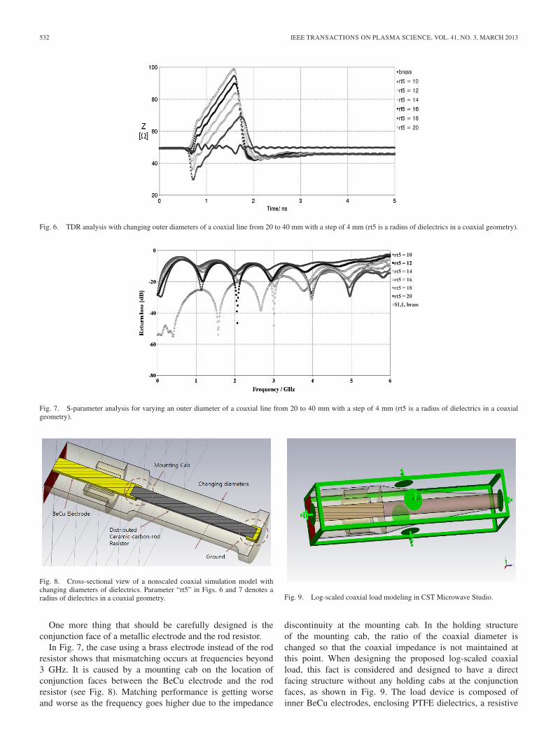
Fig. 8. Cross-sectional view of a nonscaled coaxial simulation model withchanging diameters of dielectrics. Parameter “rt5” in Figs. 6 and 7 denotes aradius of dielectrics in a coaxial geometry.
One more thing that should be carefully designed is theconjunction face of a metallic electrode and the rod resistor.
In Fig. 7, the case using a brass electrode instead of the rodresistor shows that mismatching occurs at frequencies beyond3 GHz. It is caused by a mounting cab on the location ofconjunction faces between the BeCu electrode and the rodresistor (see Fig. 8). Matching performance is getting worseand worse as the frequency goes higher due to the impedance
Fig. 9. Log-scaled coaxial load modeling in CST Microwave Studio.
discontinuity at the mounting cab. In the holding structureof the mounting cab, the ratio of the coaxial diameter ischanged so that the coaxial impedance is not maintained atthis point. When designing the proposed log-scaled coaxialload, this fact is considered and designed to have a directfacing structure without any holding cabs at the conjunctionfaces, as shown in Fig. 9. The load device is composed ofinner BeCu electrodes, enclosing PTFE dielectrics, a resistive

RYU AND KIM: COAXIAL TERMINATION LOAD FOR FAST TRANSIENT PULSE MEASUREMENT 533
Fig. 10. TDR impedance analysis: Comparison of impedance for a normal case, a nonscaled case, and a log-scaled case.
Fig. 11. Simulated return loss of the proposed log-scaled coaxial load using a100-mm distributed ceramic-carbon-rod resistor.
solid rod, and an outer metal housing, as represented in Fig. 5.The outer housing metal was modeled as a perfect electricconductor for saving analysis time. For the dielectrics, PTFEwas chosen having a dielectric constant of 2.2. For the resistivesolid rod, the commercial carbon-rod resistor of R1005A051J,produced by HVR Company Ltd., is used. BeCu electrodeswere used for inner metal electrodes. TDR and S-parameteranalysis were performed to estimate impedance variations inpercent values and matching performance in the frequencyrange of 0.1–10 GHz, respectively. Simulated results are shownin Figs. 10 and 11. In Fig. 10, the reference plot means a normalcoaxial geometry that a metal electrode is used as a centerconductor in the nonscaled coaxial structure. The nonscaledstructure represents a case that the carbon-rod resistor is usedat the position of the center conductor. A log-scaled structuredenotes an impedance-compensated case for the nonscaledstructure by means of diminishing the coaxial characteristicimpedance. A log-scaled coaxial case provides a notable im-provement in the aspect of the impedance variation. Matchingperformance was improved with ten times better than the non-scaled one.
Fig. 11 shows a simulation result of the impedance matchingperformance in the frequency domain achieving return lossbelow −20 dB up to 10 GHz. It means that a reflected powervalue is only below 1% with respect to the incident signalpower.
Fig. 12. Circuit diagram of a laboratory-developed UWB pulse generator.
Fig. 13. Three-dimensional CAD model of the Marx generator and PFNstructure in a laboratory-developed UWB pulse generator. The Marx generatoris composed of four-stage parallel capacitors, each having a charging voltagerate of 50 kV.
IV. EXPERIMENTAL SETUP
A. High-Voltage UWB Pulse Generator
A Marx generator-driven LC resonant spark-gap pulse gen-erator was designed and implemented for testing a termination
534 IEEE TRANSACTIONS ON PLASMA SCIENCE, VOL. 41, NO. 3, MARCH 2013
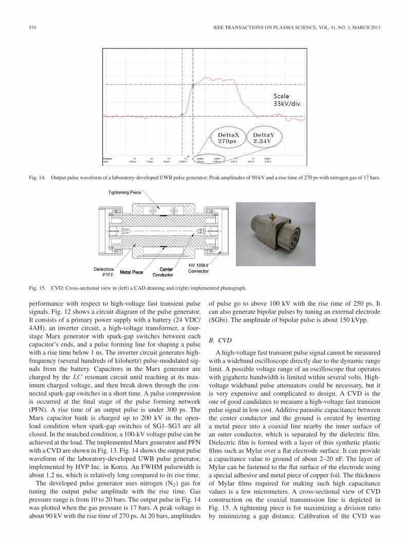
Fig. 14. Output pulse waveform of a laboratory-developed UWB pulse generator: Peak amplitudes of 90 kV and a rise time of 270 ps with nitrogen gas of 17 bars.
Fig. 15. CVD: Cross-sectional view in (left) a CAD drawing and (right) implemented photograph.
performance with respect to high-voltage fast transient pulsesignals. Fig. 12 shows a circuit diagram of the pulse generator.It consists of a primary power supply with a battery (24 VDC/4AH), an inverter circuit, a high-voltage transformer, a four-stage Marx generator with spark-gap switches between eachcapacitor’s ends, and a pulse forming line for shaping a pulsewith a rise time below 1 ns. The inverter circuit generates high-frequency (several hundreds of kilohertz) pulse-modulated sig-nals from the battery. Capacitors in the Marx generator arecharged by the LC resonant circuit until reaching at its max-imum charged voltage, and then break down through the con-nected spark-gap switches in a short time. A pulse compressionis occurred at the final stage of the pulse forming network(PFN). A rise time of an output pulse is under 300 ps. TheMarx capacitor bank is charged up to 200 kV in the open-load condition when spark-gap switches of SG1–SG3 are allclosed. In the matched condition, a 100-kV voltage pulse can beachieved at the load. The implemented Marx generator and PFNwith a CVD are shown in Fig. 13. Fig. 14 shows the output pulsewaveform of the laboratory-developed UWB pulse generator,implemented by HVP Inc. in Korea. An FWHM pulsewidth isabout 1.2 ns, which is relatively long compared to its rise time.
The developed pulse generator uses nitrogen (N2) gas fortuning the output pulse amplitude with the rise time. Gaspressure range is from 10 to 20 bars. The output pulse in Fig. 14was plotted when the gas pressure is 17 bars. A peak voltage isabout 90 kV with the rise time of 270 ps. At 20 bars, amplitudes
of pulse go to above 100 kV with the rise time of 250 ps. Itcan also generate bipolar pulses by tuning an external electrode(SGbi). The amplitude of bipolar pulse is about 150 kVpp.
B. CVD
A high-voltage fast transient pulse signal cannot be measuredwith a wideband oscilloscope directly due to the dynamic rangelimit. A possible voltage range of an oscilloscope that operateswith gigahertz bandwidth is limited within several volts. High-voltage wideband pulse attenuators could be necessary, but itis very expensive and complicated to design. A CVD is theone of good candidates to measure a high-voltage fast transientpulse signal in low cost. Additive parasitic capacitance betweenthe center conductor and the ground is created by insertinga metal piece into a coaxial line nearby the inner surface ofan outer conductor, which is separated by the dielectric film.Dielectric film is formed with a layer of thin synthetic plasticfilms such as Mylar over a flat electrode surface. It can providea capacitance value to ground of about 2–20 nF. The layer ofMylar can be fastened to the flat surface of the electrode usinga special adhesive and metal piece of copper foil. The thicknessof Mylar films required for making such high capacitancevalues is a few micrometers. A cross-sectional view of CVDconstruction on the coaxial transmission line is depicted inFig. 15. A tightening piece is for maximizing a division ratioby minimizing a gap distance. Calibration of the CVD was

RYU AND KIM: COAXIAL TERMINATION LOAD FOR FAST TRANSIENT PULSE MEASUREMENT 535
Fig. 16. Assembly configurations of cable connectors and adaptors.
Fig. 17. Assembled photograph of the proposed log-scaled load device.
performed using a commercial pulse generator of FPG 20-P,manufactured by FID GmbH in Germany. The implementedCVD device shows the division ratio of 1/330 having amplitudeup to 100 kV with the rise time below 300 ps. A division ratio ofthe CVD was evaluated by comparing the division pulse voltageof the CVD with attenuated values using the commercial high-voltage pulse attenuators, as shown in Fig. 22.
C. High-Voltage Connectors and Adaptors
Configuring measurement setup for a log-scaled coaxial loaddevice requires customized connectors and transition adaptorsfor evaluating termination performances with respect to high-voltage subnanosecond pulse signals. Fig. 16 shows assemblydrawings and pictures for the high-voltage cable connectorsand adaptors. Interface of connectors and adaptors was de-signed satisfying 50-Ω coaxial impedance and the insulationperformance over 100 kV, i.e., same with the proposed log-scaled load device (see Fig. 17). A grooved structure on thedielectric surface of connectors and adaptors also provides aconvenient feature to change from female geometry to maleone by fitting a grooved hole with a dielectric ring and apiece of internal electrode. Cable connectors are configured toallow the core of the high-voltage coaxial cable to be coupledwith the inner electrode of the connector in a threaded mannerso that assembling and disassembling are easier rather thansoldering way. An insertion loss of a fabricated high-voltagecable assembled with connectors at both ends is measured with0.45 dB/m at 1 GHz, and return loss is below −20 dB from40 MHz to 10 GHz.
D. Measurement Setup
Measurement setup for a high-voltage impulse termination isshown in Fig. 18. A pulse generator is made up of two differenttypes of sources. One is a commercial semiconductor switch-based pulse generator, FPG 20-P, and the other is a laboratory-developed spark-gap switch-based UWB pulse generator. TDRresults with FPG 20-P would provide operation frequencyvalidity up to 10 GHz for the proposed load device, but it cannotshow the voltage insulation capability up to 100 kV becausethe maximum output voltage is limited less than 20 kV. Thedeveloped UWB pulse generator can give a validity of the high-voltage insulation performance up to 100 kV but cannot giveany information of its frequency usage up to 10 GHz, viceversa. Table I represents electrical specifications of two testsources in detail.
FPG 20-P shows an amplitude of < 20 kV, a rise time of< 150 ps, and repetition rates of < 10 kHz. The laboratory-developed UWB source shows an amplitude of < 100 kV, a risetime of < 300 ps, and repetition rates of < 100 Hz. Both twosources have an output impedance value of 50 Ω.
In Fig. 18, an in-house developed high-voltage coaxial cableassembled with connectors connects the output of a pulsegenerator to the input of the CVD device. The division port ofthe CVD is connected to 40-dB pulse attenuators, manufacturedin Barth Electronics Inc., and the output port of the CVD islinked to the input of the proposed coaxial load device through a100-kV male-to-male adaptor. Scaling factor of an oscilloscopeis 1/33 000 since the division ratio of the CVD is about 1/330.Small-signal test setup is not explained in detail, but a vectornetwork analyzer of 37347C, manufactured in Anritsu Cor-poration, is used with in-house developed cable-type adaptorstransforming from a 100-kV interface to an n-type interface.
V. EXPERIMENTAL RESULTS
A. UWB Frequency Performance
The small-signal network performance of an impedancematching property is measured from 40 MHz to 10 GHz, asshown in Fig. 19. Return loss is below −20 dB in the entiretest frequency band. The solid line represents a measured returnloss plot of the proposed log-scaled load device, and the dottedline denotes a simulated result in CST Microwave Studio.

536 IEEE TRANSACTIONS ON PLASMA SCIENCE, VOL. 41, NO. 3, MARCH 2013
Fig. 18. Test configurations of termination performance of a load device for high-voltage fast transient pulses using the CVD and load.
TABLE ISPECIFICATIONS OF TWO DIFFERENT TYPES OF UWB PULSE GENERATORS
Fig. 19. Return loss plot of the proposed log-scaled load device: (dotted line)simulated result and (solid line) measured result.
Measured performance is well coincident with the simulated re-sults except frequencies above 6 GHz. It might be caused by thecable-type conversion adaptors having similar S11 trajectory inFig. 19.
Fig. 20 shows a comparison of a measured return loss be-tween the nonscaled and proposed log-scaled structures. Returnloss is notably enhanced in the entire test frequency band. Asaforementioned, the nonscaled load device does not operate asa proper termination device and may cause serious errors in theanalysis data. Matched impedance property may be expressedwith a TDR analysis in the time domain.
We used a TDR scope, a model of TDS520, produced byTektronix.
A pulse generator in the TDR equipment generates a fasttransient impulse with a rise time of 20 ps, and its output
Fig. 20. Measured return loss plots of two types of a load device: (dotted line)nonscaled structure and (solid line) log-scaled structure.
Fig. 21. Measured TDR plot for the proposed log-scaled load device.
impedance is 50 Ω. Fig. 21 represents a measured TDR per-formance of the log-scaled load device.
In the TDR plot, impedance is finally converged to 54.86 Ωafter passing through the log-scaled coaxial load device. Fluc-tuations of the impedance might be caused by discontinuedconjunction faces in the adaptor and components of the loaddevice. The reason we analyzed that impedance peaking iscaused by the discontinuity in the load device is the fact thatthe location of the peak value is coincident with conjunctionsurfaces between the transition electrode and the carbon re-sistor, as shown in Fig. 5. Results of S-parameter and TDRanalysis imply that the proposed log-scaled structure is useful

RYU AND KIM: COAXIAL TERMINATION LOAD FOR FAST TRANSIENT PULSE MEASUREMENT 537
Fig. 22. Comparison of measured pulse waveforms between an attenuated case (see the left test setup) and a coupled case using a CVD with the log-scaled load(see the right test setup) applying output pulses of FPG 20-P in wide temporal span (5 ns/div.).
Fig. 23. Measured pulse waveforms of an attenuated case and a coupled case using a CVD with the log-scaled load in narrow temporal span (500 ps/div.).
for obtaining performances of high-voltage insulation andUWB frequency simultaneously even using an electrically longdistributed resistor.
B. High-Voltage Pulse Termination Performance
A high-voltage repetitive pulse termination is evaluated usingan experimental setup, as shown in Fig. 18. High-voltage oper-ation is diagnosed by measuring reflected pulses at the divisionport of the CVD in the predictable time range of 15 ns whenreflection occurs at the conjunction point of the CVD and theload device. In Fig. 18, a high-voltage coaxial cable with in-house implemented connectors is 1.2-m long and the length ofthe CVD device is about 10 cm. Measured reflected pulses arerepresented in Figs. 22 and 23. In Figs. 22 and 23, FPG 20-Pwas used as a test source. Two cases were benchmarked thatone is a case of using commercial pulse attenuators (see the leftpicture of the test setup in Fig. 22) and the other is a case ofusing in-house developed CVD with the log-scaled load (seethe right picture of the test setup in Fig. 22) device.
Additional two 20-dB attenuators of Barth Electronics Inc.are used in cascade at the division port of the CVD. Both casesrepresent almost the same waveforms in aspects of a rise timeand peak voltage amplitudes. In addition, there are no reflectionpulses after an incident pulse within 15 ns, which means thatthe attached load device to the CVD output provides excellentimpedance matching performance with respect to a pulsed inputin that of amplitudes up to 20 kV, a rise time below 150 ps,and repetition rates below 10 kHz. For investigating maximumoperation voltage, a laboratory-developed UWB pulse gener-ator was used in a test configuration in Fig. 18. Measuredpulse waveform at the division port of the CVD with additionalattenuation of 40 dB is plotted in Fig. 24.
An output pulse amplitude in Fig. 24 is about 114.5 kV, anda rise time is about 250 ps. Time and amplitude resolutions are5 ns/div. and 100 V/div., respectively. Attenuators connectedto the division port of the CVD are calibrated by setting offsetvalues with 1/100 in an oscilloscope. As shown in Fig. 24, thereare no reflected pulses within 25 ns after a time spot where apeak pulse is detected.

538 IEEE TRANSACTIONS ON PLASMA SCIENCE, VOL. 41, NO. 3, MARCH 2013
Fig. 24. Measured pulse waveforms using a CVD with the log-scaled load device applying a 114.5-kV pulse using a laboratory-developed UWB pulse generatorin wide temporal span (5 ns/div.).
VI. SUMMARY AND CONCLUSION
In this paper, we have presented a design method and evalua-tion results of the log-scaled coaxial load device for terminatingthe high-voltage subnanosecond pulse signals using a 10-cmdistributed ceramic-carbon-rod resistor. The physical length ofa rod resistor is far longer than a wavelength of an input pulseso that impedance linearly increases in the moving direction ofan incoming pulse. A proposed high-voltage UWB log-scaledcoaxial load with a distributed ceramic-carbon-rod resistor hasa property to compensate the varying impedance, which iscaused by an electrically long rod resistor by means of dimin-ishing the coaxial characteristic impedance exponentially alongthe resistor. Consequently, it can provide consistent impedancein the entire load device.
Experiments are performed with TDR and S-parameter anal-ysis to verify small-signal wideband performance. For highvoltage diagnostics verifying the high-voltage operation va-lidity, commercial FPG 20-P and laboratory-developed UWBpulse generator are used. FPG 20-P has a performance of anamplitude of < 20 kV, a rise time of 100–150 ps, and repetitionrates of < 10 kHz. The laboratory-developed UWB pulsegenerator has output amplitudes of 100 kV at gas pressuresof 20 bar, a variation range from 50 to 100 kV by controllinggas pressures, and a rise time of 250–300 ps with a maximalrepetition frequency of 100 Hz.
The UWB capacitive voltage probe device (CVD), whichhas a division ratio of 1/330, is also implemented and usedto measure a high-voltage pulse reflection in the time domain.Experimental results show good agreement with expectationsfor the voltage standing-wave ratio under 1.25 : 1 from dc to10 GHz, a peak impedance variation under 10%, and a stabi-lized value of 54.86 Ω with negligible reflections. An injectedinput pulse has amplitudes from 15 to 100 kV, a rise timebelow 1 ns, and repetition rates under 10 kHz. The proposedcoaxial load device is adequate for terminating a high-voltagefast transient pulse signal of which the duty cycle is below0.001% because of a capacity of heat dissipation of the rodresistor.
ACKNOWLEDGMENT
The authors would like to thank Dr. W.-H. Kim and HVP Inc. inKorea for cooperating and advising in the high-voltage pulse test.
REFERENCES
[1] T. Weber, “Measurement techniques for conducted HPEM signals,” IEEETrans. Electromagn. Compat., vol. 46, no. 3, pp. 431–438, Aug. 2004.
[2] M. Camp, “Susceptibility of personal computer systems to fast transientelectromagnetic pulses,” IEEE Trans. Electromagn. Compat., vol. 48,no. 4, pp. 829–833, Nov. 2006.
[3] D. Nitsch, “Susceptibility of some electronic equipment to HPEM threats,”IEEE Trans. Electromagn. Compat., vol. 46, no. 3, pp. 380–389, Aug. 2004.
[4] M. Bäckström, “Susceptibility of electronic systems to high-power mi-crowaves: Summary of test experience,” IEEE Trans. Electromagn.Compat., vol. 46, no. 3, pp. 396–403, Aug. 2004.
[5] D. Nitsch, “Prediction of ultra wide band coupling to modern electronicequipment,” in Proc. EMC, Wroclaw, Poland, Jun. 2002, pp. 103–108.
[6] H. Akiyama, “Industrial applications of pulsed power technology,” IEEETrans. Dielect. Elect. Insul., vol. 14, no. 5, pp. 1051–1064, Oct. 2007.
[7] Z. Fang, “Surface treatment of polyethylene terephthalate films using amicrosecond pulse homogeneous dielectric barrier discharges in atmo-spheric air,” IEEE Trans. Plasma Sci., vol. 38, no. 7, pp. 1615–1623,Jul. 2010.
[8] M. Sira, “Surface modification of polyethylene and polypropylene inatmospheric pressure glow discharge,” J. Phys. D, Appl. Phys., vol. 38,no. 4, pp. 621–627, Feb. 2005.
[9] T. Tang, “Diode opening switch based nanosecond high voltage pulsegenerators for biological and medical applications,” IEEE Trans. Dielect.Elect. Insul., vol. 14, no. 4, pp. 878–883, Aug. 2007.
[10] A. Kuthi, “Nanosecond pulse generator using fast recovery diodes for cellelectromanipulation,” IEEE Trans. Plasma Sci., vol. 33, no. 4, pp. 1192–1197, Aug. 2005.
[11] A. Pokryvailo, “A compact source of subgigawatt subnanosecond pulses,”IEEE Trans. Plasma Sci., vol. 32, no. 5, pp. 1909–1918, Oct. 2004.
[12] S. Lyubutin, “High-power ultrafast current switching by a silicon sharp-ener operating at an electric field close to the threshold of the Zenerbreakdown,” IEEE Trans. Plasma Sci., vol. 38, no. 10, pp. 2627–2632,Oct. 2010.
[13] L. Pecastaing, “Very fast rise-time short-pulse high-voltage generator,”IEEE Trans. Plasma Sci., vol. 34, no. 5, pp. 1822–1829, Oct. 2006.
[14] K. Liu, “A high repetition rate nanosecond pulsed power supply fornonthermal plasma generator,” IEEE Trans. Plasma Sci., vol. 33, no. 4,pp. 1182–1185, Aug. 2005.
[15] G. Mesyats, “The RADAN series of compact pulsed power generators andtheir applications,” Proc. IEEE, vol. 92, no. 7, pp. 1166–1179, Jul. 2004.
[16] B. Cadilhon, “High pulsed power sources for broadband radiation,” IEEETrans. Plasma Sci., vol. 38, no. 10, pp. 2593–2603, Oct. 2010.
[17] C. Spikings, “High performance attenuator,” in Proc. IEE Symp. PulsedPower (Dig. 1999/030), 1999, pp. 15/1–15/6.

RYU AND KIM: COAXIAL TERMINATION LOAD FOR FAST TRANSIENT PULSE MEASUREMENT 539
Seung-Kab Ryu was born in Seoul, Korea, in 1976.He received the B.S. degree in avionics in 1999 fromHankuk Aviation University, Goyang, Korea, and theM.S. degree in mechatronics in 2001 from GwangjuInstitute of Science and Technology, Gwangju,Korea, where he is currently working toward thePh.D. degree.
From 2001 to 2004, he was with Millitron Inc.,as the Senior Engineering Staff for the developmentof millimeter-wave transceiver and outdoor unit de-velopment. He is currently with the Convergence
Technology Department, Attached Institute of Electronics and Telecommuni-cation Research Institute, Daejeon, Korea. His research interests are in thedevelopment of high-voltage plasma limiter for high-power microwave protec-tion and subnanosecond pulsed-power source for intentional electromagneticinterference immunity research on microwave and wireless equipment pieces.
Yong-Hoon Kim (M’90) was born in Donghae,Korea, in 1952. He received the B.S. degree in radioscience and engineering from Kyung Hee University,Seoul, Korea, in 1974; the M.S. degree in elec-tronic engineering from Yonsei University, Seoul, in1976; and the Dr.-Ing. degree from the University ofStuttgart, Stuttgart, Germany, in 1990.
From 1976 to 1980, he was an Instructor with theSecond Air Force Academy in Korea. From 1990 to1994, he was with Korea Aerospace Research Insti-tute as the Department Head of Space Application
Technology, Avionics, and Space Payload. Since 1995, he has been a Professorwith the School of Information and Mechatronics, Gwangju Institute of Scienceand Technology, Gwangju, Korea. Since then, he has contributed to the devel-opment of microwaves, millimeter-wave components, millimeter-wave activeand passive imaging systems, and high-speed millimeter-wave communica-tion systems. He is currently focused on the medical application of radars,radiometers for noninvasive measurement, and millimeter-wave polarimetricimage radiometers. He is also focused on CMOS one-chip SoC for laboratory-developed radar and radiometer systems. In 2000, he founded Millisys Inc.,Gwangju, where has been a representative. As a result of outstanding researchactivities in his field, he holds several patents for method and apparatus forobtaining high-resolution images in Korea, the U.S., and Japan.
Dr. Kim is a Board Member of the Korean Society of Remote Sensing andthe Korean Institute of Electromagnetic Engineering and Science.