
COAXIAL NARROWBAND FILTERS USING A VERSATILE - PIER
16
Progress In Electromagnetics Research, Vol. 115, 79–94, 2011 COAXIAL NARROWBAND FILTERS USING A VERSATILE SUSPENDED RESONATOR A. Jaimes-Vera and I. Llamas-Garro † Centre Tecnologic de Telecomunicacions de Catalunya (CTTC) Barcelona 08860, Spain A. Corona-Chavez National Institute for Astrophysics, Optics and Electronics Puebla 72840, M´ exico Abstract—In this paper, two four-pole filters at X-band are presented, both designs use a coaxial quarter wavelength resonator suspended in air by short circuits between the coaxial center and outer conductor. Different couplings between suspended resonators have been used to obtain a Chebyshev and a quasi-elliptic response. The Chebyshev filter was designed to have a 9.2GHz centre frequency with a 4% fractional bandwidth. The second design is a quasi-elliptic filter composed of two vertically stacked rectangular coaxial lines, where one pair of resonators is placed on the lower coaxial line and another pair is located on the upper line. Coupling between coaxial lines is achieved through an iris in the common coaxial ground plane. The quasi-elliptic filter has been designed to have a centre frequency of 9.1 GHz with a 4% fractional bandwidth. Two transmission zeros located at the sides of the passband have been successfully achieved with the proposed filter topology. Experimental results for both designs are presented, where a good agreement with simulations has been obtained. 1. INTRODUCTION Combline and interdigital filters have been widely used in many applications, such as cellular communications base-stations. Present filter generations for mobile communications require high performance Received 4 February 2011, Accepted 17 March 2011, Scheduled 22 March 2011 Corresponding author: Ignacio Llamas-Garro ([email protected]). † A. Jaimes-Vera is also with Signal Theory and Communications Department, Technical University of Catalonia, 08034 Barcelona, Spain.
Transcript of COAXIAL NARROWBAND FILTERS USING A VERSATILE - PIER

Progress In Electromagnetics Research, Vol. 115, 79–94, 2011
COAXIAL NARROWBAND FILTERS USING AVERSATILE SUSPENDED RESONATOR
A. Jaimes-Vera and I. Llamas-Garro †
Centre Tecnologic de Telecomunicacions de Catalunya (CTTC)Barcelona 08860, Spain
A. Corona-Chavez
National Institute for Astrophysics, Optics and ElectronicsPuebla 72840, Mexico
Abstract—In this paper, two four-pole filters at X-band are presented,both designs use a coaxial quarter wavelength resonator suspended inair by short circuits between the coaxial center and outer conductor.Different couplings between suspended resonators have been used toobtain a Chebyshev and a quasi-elliptic response. The Chebyshev filterwas designed to have a 9.2GHz centre frequency with a 4% fractionalbandwidth. The second design is a quasi-elliptic filter composed of twovertically stacked rectangular coaxial lines, where one pair of resonatorsis placed on the lower coaxial line and another pair is located onthe upper line. Coupling between coaxial lines is achieved throughan iris in the common coaxial ground plane. The quasi-elliptic filterhas been designed to have a centre frequency of 9.1 GHz with a 4%fractional bandwidth. Two transmission zeros located at the sides ofthe passband have been successfully achieved with the proposed filtertopology. Experimental results for both designs are presented, wherea good agreement with simulations has been obtained.
1. INTRODUCTION
Combline and interdigital filters have been widely used in manyapplications, such as cellular communications base-stations. Presentfilter generations for mobile communications require high performance
Received 4 February 2011, Accepted 17 March 2011, Scheduled 22 March 2011Corresponding author: Ignacio Llamas-Garro ([email protected]).
† A. Jaimes-Vera is also with Signal Theory and Communications Department, TechnicalUniversity of Catalonia, 08034 Barcelona, Spain.
80 Jaimes-Vera, Llamas-Garro, and Corona-Chavez
filters, with high selectivity and good out of band rejection, includingdevice miniaturization. The performance of conventional filters can beimproved by introducing transmission zeros at the sides of the bandpassresponse to achieve sharp selectivity with good out of band rejection [1–5].
Commonly coaxial-combline cavity filters with transmission zeroshave been designed by means of coupling probes embedded in thefilter fixture [6], also the use of extra cavities or small metal platesamong the resonators [7, 8] have been used. The designs presentedin this paper use a suspended resonator into a multilayer structure;allowing different coupling arrangements to produce electric, magneticand mixed couplings, enabling quasi-elliptic function approximation orflat group delay responses, without using extra coupling probes, extracavities or folded structures. The multilayer structure can provide awide range of couplings, an easy introduction of cross couplings andsize reduction [9–12]. The proposed resonator is a quarter wavelengthlong suspended by stubs, suitable for the design of narrowband filtersusing coaxial lines. A wideband coaxial filter can be found in [13]. Thispaper provides the design and implementation of a Chebyshev filter, adescription of the feed line used to interconnect the devices with themeasurement equipment, and a detailed design and characterization ofa quasi-elliptic filter.
This paper presents the design and development of Chebyshevand quasi-elliptic filters at around 9 GHz, where only few works canbe found [10, 14–16], since most of combline and interdigital filters aredesigned between 1 and 2 GHz for mobile communications. Table 1shows a list of coaxial/combline/interdigital filters operating between1 and 9GHz including their most outstanding features. A comparisonamong combline or interdigital filters and the work presented in thispaper has been done. The unloaded quality factor [17] for each designhas been calculated from measured results using Eq. (1). Where theg′s are the lowpass element values, BW is the filter 3 dB bandwidthand IL is the mid passband insertion loss.
Q0 =4.34
∑ni=1 gi
BW IL(1)
It is apparent from Table 1 that the devices presented in this paperhave a quality factor between the high Q obtained through optimizedconventional coaxial-combline designs and interdigital or microstrip-combline filters. The filters presented in this paper are made fromplanar metal layers; this implementation allows scaling the designs tomillimeter wave frequencies, using micromachined structures [18].
The structures here presented were implemented into air-filledcoaxial lines using stacked planar layers, avoiding radiation and

Progress In Electromagnetics Research, Vol. 115, 2011 81
Table 1. Performance summary of coaxial, combline and interdigitalfilters operating in a frequency range from 1 to 9 GHz.
Primary Author Chuma
[19]
Zheyu
[20]
Yi-Ming
[21]
Yani
[9]
Shih-Cheng
[22]
Ying
[8]
Huan
[23]
Hoi-Kai
[24]
Ting
[25]
Tao
[26]
Chi-Yang
[27]
This
paper
This
paper
Year 2000 2008 2006 2005 2007 2009 2009 2004 2004 2007 2001
Technology Cx Cb Cb In Cb Cx Cx In In Cb In Cx Cx
Filter Function E C E E E E E B B C C C E
Number of
resonators 4 5 4 4 2 6 3 3 3 5 3 4 4
Central
Freq uency (GHz) 1.747 2.0175 2.4 2.25 1.43 1.54 1.73 0.7 0.9 9.6 9.5 9.2 9.1
Fr actional
Bandwidth (%) 4.3 0.75 4.2 31 11.5 3.2 4.5 12 15 8 10 5.7 2.88
Insertion Loss
(dB) 0.46 1.49 1.2 1.0 2.78 - 0.77 1.3 1.5 1.93 2.5 1.07 1.7
Qo from Eq.(1) 897 2602 352 57 343 139 96 188 56 355 166
Midband Return
Loss (dB) >15 >20 >25 >15 >18 >20 >17 >10 >9 >20 >12 >17 >20
Area (cm2) 2.36 1.3 5.32 19.25 21 - 0.16
Volume (cm3) 57.5 30.34 284.47 90 - 23.14 29.03
Cx-Coaxial Filter Cb-Combline Filter In-Interdigital Filter
E-Elliptic Function C- Chebyshev Function B-Butterworth Function
dielectric losses and crosstalk between adjacent lines. The use ofa multilayer structure allowed size reduction and a wide range ofpossible couplings between versatile resonators. The introduction ofcross couplings has been achieved without the use of additional cavitiesor coupling probes. These filters show a competitive response and agood balance among losses, size and quality factor; furthermore filterimplementation using stacked planar layers allows scaling the devicesto the millimeter wave region using micromachining techniques.
2. SUSPENDED COAXIAL RESONATOR AND FEEDLINE
The quarter wavelength resonator suspended by short circuits insidean air filled rectangular coaxial cable used to design the filers presentedin this paper is shown in Fig. 1(a). The resonator has the maximummagnetic field density next to the short circuited stubs, and themaximum electric field at the opposite side, as shown in Fig. 1(b)

82 Jaimes-Vera, Llamas-Garro, and Corona-Chavez
(a) (b)
Figure 1. Suspended quarter wavelength resonator (a) Schematicof the quarter wavelength resonator (side and top walls removed forclarity). (b) Surface current distribution at a resonant frequency of9.1GHz.
where surface current distribution at the resonant frequency of 9.1 GHzis plotted. Therefore electric, magnetic and mixed couplings can beobtained by choosing adequate resonator configurations [28]. Thedifferent inter-resonator arrangements and coupling types that can beachieved with the proposed resonator are shown in Fig. 2. By placingthe two short circuited sides of the resonator facing each other, asshown in Fig. 2(a), a magnetic coupling can be obtained. Electriccoupling can be attained by placing side by side the open end of theresonators as shown in Fig. 2(b). It is apparent from Fig. 2 that theresponse of the electric and magnetic coupling arrangements are outof phase; these couplings have been used to produce the quasi-ellipticfilter discussed in Section 4. Mixed couplings have been obtained byplacing resonators on different coaxial layers, coupled by an iris on thecommon coaxial ground plane between them as shown in Fig. 2(c).
A suspended transmission line is used to interface the rectangularcoaxial filters for measurements. Fig. 3(a) shows a photograph of the50Ω suspended feed line used to input/output energy to the filter in aback-to-back configuration. This transmission line has been optimizedby simulations to minimize reflection losses at the transitions withround connectors. A slot on both sides of the feed line is used tomount SMA connectors (see Fig. 3(b)). This transmission line isformed by the union of five copper layers, the overall dimensions of thetransmission line are 26 × 29.8 × 12mm3, and the technical drawingof layer 3 is presented in Fig. 3(b). The final feed line is a pieceof coaxial transmission line all surrounded by air, and suspended byquarter wavelength transmission line stubs at the center frequency of

Progress In Electromagnetics Research, Vol. 115, 2011 83
(a)
(b)
(c)
Figure 2. Inter-resonator couplings, (a) Magnetic coupling. (b)Electric coupling. (c) Mixed coupling.
the filters; resulting in an open circuit were the stub makes contactwith the coaxial center conductor.
Simulated and measured results of the suspended transmission linein a back-to-back configuration are presented in Fig. 4. All simulationswere done using HFSS considering a copper conductivity value of5.8 × 107 S/m. The differences between the simulated and measuredresponse is caused by fabrication tolerances related to the designspresented in this paper, which are discussed in detail in Section 5.

84 Jaimes-Vera, Llamas-Garro, and Corona-Chavez
(a) (b)
Figure 3. Coaxial feed line in a back-to-back configuration (a)Photograph of the coaxial feed line. (b) Technical drawing of thecoaxial feed line, layer 3 (dimensions in millimeters).
Figure 4. Simulated and mea-sured response of the coaxial feedline in a back-to-back configura-tion.
Figure 5. Photograph of thecoaxial Chebyshev filter.
3. NARROWBAND CHEBYSHEV COAXIAL FILTER
In this section, a narrowband coaxial filter with a Chebyshev responseis presented. The filter was designed using rectangular coaxialtransmission lines, where the resonators are suspended along with thefeed lines that provide the input/output to the device, as shown inFig. 5. The entire topology is formed by five conductive layers stackedand compressed together to obtain the coaxial filter.
The design procedure for this filter follows the methodologyprovided in [17], which consists in calculating the coupling coefficientsbetween resonators (Kij ) and the external quality factor (Qe), achieved

Progress In Electromagnetics Research, Vol. 115, 2011 85
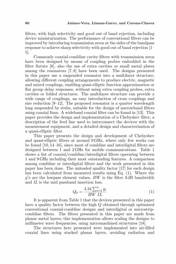
by full wave simulations using HFSS. The equations to obtain thetheoretical couplings between resonators and the external qualityfactor can also be found in [17]. The design data and parameters usedfor this filter are summarized in Table 2, which contains the lowpasselement g values, the required Kij and Qe for the design. The externalquality factor (Qe) obtained by electromagnetic simulations is shownin Fig. 6, similarly inter-resonator couplings (Kij ) are shown in Fig. 7.The filter was designed at 9.2 GHz with a 0.01 dB passband ripple anda 4% fractional bandwidth. A lumped element equivalent circuit forthe Chebyshev filter is presented in Fig. 8.
The filter is formed by five layers, which are stacked andcompressed together. Layer 3 is the main layer, which contains thefour resonators and the feed lines, layers 2 and 4 create a coaxial cavity,and finally layers 1 and 5 shield the complete structure. The overall
Figure 6. External quality factor (Qe) for the coaxial filters.
(a) (b)
Figure 7. Coupling coefficients for the Chebyshev filter. (a) Couplingcoefficient between resonators 1 and 2. (b) Coupling coefficientbetween resonators 2 and 3.
86 Jaimes-Vera, Llamas-Garro, and Corona-Chavez
Figure 8. Equivalent circuit for the Chebyshev filter.
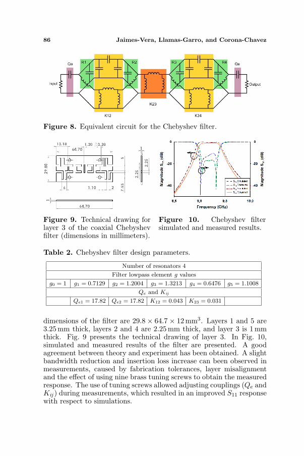
Figure 9. Technical drawing forlayer 3 of the coaxial Chebyshevfilter (dimensions in millimeters).
Figure 10. Chebyshev filtersimulated and measured results.
Table 2. Chebyshev filter design parameters.
Number of resonators 4
Filter lowpass element g values
g0 = 1 g1 = 0.7129 g2 = 1.2004 g3 = 1.3213 g4 = 0.6476 g5 = 1.1008
Qe and Kij
Qe1 = 17.82 Qe2 = 17.82 K12 = 0.043 K23 = 0.031
dimensions of the filter are 29.8 × 64.7 × 12mm3. Layers 1 and 5 are3.25mm thick, layers 2 and 4 are 2.25 mm thick, and layer 3 is 1 mmthick. Fig. 9 presents the technical drawing of layer 3. In Fig. 10,simulated and measured results of the filter are presented. A goodagreement between theory and experiment has been obtained. A slightbandwidth reduction and insertion loss increase can been observed inmeasurements, caused by fabrication tolerances, layer misalignmentand the effect of using nine brass tuning screws to obtain the measuredresponse. The use of tuning screws allowed adjusting couplings (Qe andKij ) during measurements, which resulted in an improved S11 responsewith respect to simulations.
Progress In Electromagnetics Research, Vol. 115, 2011 87
4. NARROWBAND QUASI-ELLIPTIC COAXIAL FILTERUSING VERTICALLY STACKED COAXIAL LINES
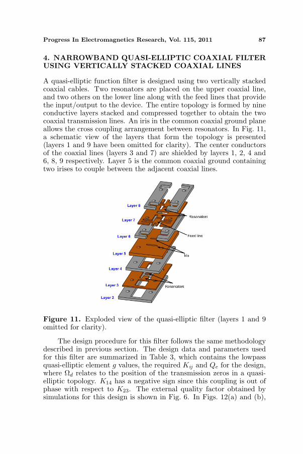
A quasi-elliptic function filter is designed using two vertically stackedcoaxial cables. Two resonators are placed on the upper coaxial line,and two others on the lower line along with the feed lines that providethe input/output to the device. The entire topology is formed by nineconductive layers stacked and compressed together to obtain the twocoaxial transmission lines. An iris in the common coaxial ground planeallows the cross coupling arrangement between resonators. In Fig. 11,a schematic view of the layers that form the topology is presented(layers 1 and 9 have been omitted for clarity). The center conductorsof the coaxial lines (layers 3 and 7) are shielded by layers 1, 2, 4 and6, 8, 9 respectively. Layer 5 is the common coaxial ground containingtwo irises to couple between the adjacent coaxial lines.
Figure 11. Exploded view of the quasi-elliptic filter (layers 1 and 9omitted for clarity).
The design procedure for this filter follows the same methodologydescribed in previous section. The design data and parameters usedfor this filter are summarized in Table 3, which contains the lowpassquasi-elliptic element g values, the required Kij and Qe for the design,where Ωd relates to the position of the transmission zeros in a quasi-elliptic topology. K14 has a negative sign since this coupling is out ofphase with respect to K23. The external quality factor obtained bysimulations for this design is shown in Fig. 6. In Figs. 12(a) and (b),
88 Jaimes-Vera, Llamas-Garro, and Corona-Chavez
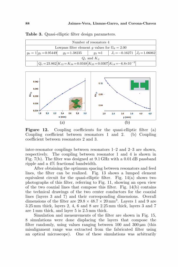
Table 3. Quasi-elliptic filter design parameters.
Number of resonators 4
Lowpass filter element g values for Ωd = 2.00
g0 = 1 g1 =0.95449 g2 =1.38235 g3 ≈1 J1 =−0.16271 J2 =1.06062
Qe and Kij
Qe =23.862 K12 =K34 =0.0348 K23 =0.0307 K14 =−6.8×10⁻³
(a) (b)
Figure 12. Coupling coefficients for the quasi-elliptic filter (a)Coupling coefficient between resonators 1 and 2. (b) Couplingcoefficient between resonators 2 and 3.
inter-resonator couplings between resonators 1–2 and 2–3 are shown,respectively. The coupling between resonator 1 and 4 is shown inFig. 7(b). The filter was designed at 9.1 GHz with a 0.01 dB passbandripple and a 4% fractional bandwidth.
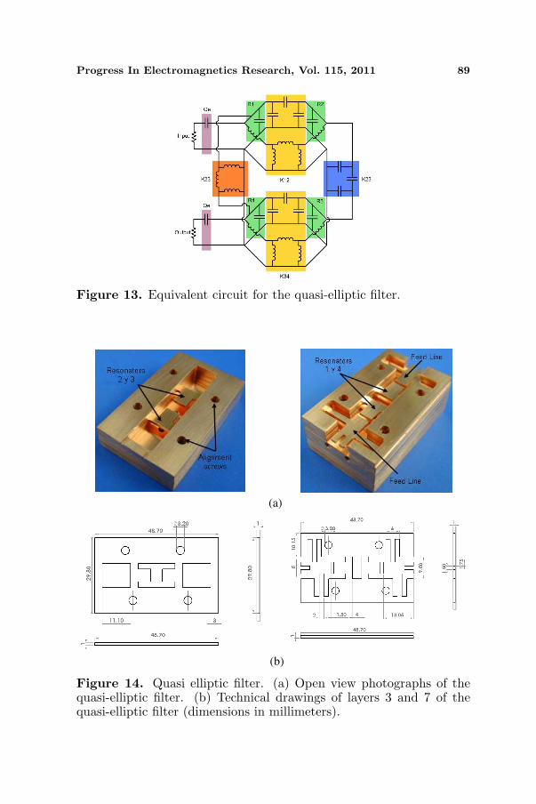
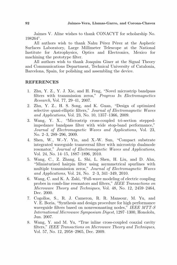
After obtaining the optimum spacing between resonators and feedlines, the filter can be realized. Fig. 13 shows a lumped elementequivalent circuit for the quasi-elliptic filter. Fig. 14(a) shows twophotographs of this filter, referring to Fig. 11, showing an open viewof the two coaxial lines that compose this filter. Fig. 14(b) containsthe technical drawings of the two center conductors for the coaxiallines (layers 3 and 7) and their corresponding dimensions. Overalldimensions of the filter are 29.8 × 48.7 × 20mm3. Layers 1 and 9 are3.25mm thick, layers 2, 4, 6 and 8 are 2.25 mm thick, layers 3 and 7are 1 mm thick, and layer 5 is 2.5mm thick.
Simulation and measurements of the filter are shown in Fig. 15,8 simulations were done displacing the layers that compose thefilter randomly, using values ranging between 100 and 300µm (thismisalignment range was extracted from the fabricated filter usingan optical microscope). One of these simulations was arbitrarily
Progress In Electromagnetics Research, Vol. 115, 2011 89
Figure 13. Equivalent circuit for the quasi-elliptic filter.
(a)
(b)
Figure 14. Quasi elliptic filter. (a) Open view photographs of thequasi-elliptic filter. (b) Technical drawings of layers 3 and 7 of thequasi-elliptic filter (dimensions in millimeters).

90 Jaimes-Vera, Llamas-Garro, and Corona-Chavez
Figure 15. Simulated and measured results for the quasi-elliptic filterimplemented on stacked coaxial lines.
selected to be included in Fig. 15. The effect of fabrication tolerancesis discussed in detail in Section 5. A good agreement betweensimulated and measured results was obtained. The increase in lossesis attributed to the use of eight brass tuning screws and a reduction inbandwidth which is associated with higher insertion losses in generalfilter implementation. The measured bandwidth decreased from 4%considered for the design to 2.88% experimentally, the simulation withmisaligned layers showed a bandwidth of 3.44%. The transmissionzero on each side of the passband was successfully achieved using theproposed vertically integrated coaxial filter topology.
5. TOLERANCE STUDY
This section presents an analysis of the fabrication tolerancesassociated with the devices presented in this paper. Fabricationtolerances include: layer misalignment, rounded corners andfabrication inaccuracies. Rounded corners arise from using a 2millimeter diameter tool to manufacture main parts of the devices,layer misalignment is related to unwanted displacements between thelayers that form the devices, and finally fabrication inaccuracies relateto deviations in the dimensions of each fabricated layer with respectto device blueprints.
A fabrication tolerance study has been carried out on the quasi-elliptic filter, to understand the inherent fabrication inaccuraciesrelated with the devices presented in this paper. These toleranceshave been characterized and studied. Firstly each piece of the devicehas been measured using an optical microscope and compared withthe blueprints provided for their fabrication. A fabrication deviationinaccuracy between 40 and 100µm has been observed on the pieces.

Progress In Electromagnetics Research, Vol. 115, 2011 91
Using the optical microscope, the misalignment tolerancesbetween layers have been extracted, and found to be in between100 and 300µm among layers. Misalignment tolerances have beensimulated using HFSS to understand the diverse effects that theseproduce on the frequency response of the device (note that pieceinaccuracy contributes to this overall misalignment among layers).Layer misalignment produces overlaps between layers that result ina reduction of coupling coefficients, producing bandwidth reductionsbetween 7 and 23.8%. These overlaps also slightly change resonatordimensions, which causes slight frequency shifts on the filter response.
The effect of rounded corners present on the manufactured devicehas been studied. Through simulations, rounded corners on theresonators produce a 13.5% reduction in bandwidth with respect toa device presenting perfectly straight edges. Rounded corners on otherparts of the device present negligible effects.
The combination of the diverse fabrication tolerances onimplemented devices produces deviations in the filter measuredresponses with respect to simulations. In this section, the effect ofeach type of tolerance has been considered separately. Considering asimulation with all tolerances together has been avoided due to thecomplexity of the optical measurements and simulations, neverthelessgood understanding of the deviations present in the responses due tofabrication tolerances has been addressed. Micromachining techniquescan provide more precisely constructed layered devices operating athigher frequencies.
6. CONCLUSION
Two coaxial filters have been successfully designed and characterizedat X-band using the proposed versatile suspended coaxial resonator,which allows the design of cross coupled filters. A new type ofnarrowband quasi-elliptic filter using vertically stacked coaxial lineshas been presented. The filter uses cross-couplings to produce aquasi-elliptic response with a pair of transmission zeros. The filterimplementation using planar machined metal layers allows scalingthe designs to millimeter wave frequencies using micromachiningtechniques.
ACKNOWLEDGMENT
This work has been financed by research Project PIB2010BZ-00585from the Spanish ministry of science and innovation.
92 Jaimes-Vera, Llamas-Garro, and Corona-Chavez
Jaimes V. Aline wishes to thank CONACYT for scholarship No.198264.
All authors wish to thank Nahu Perez Perez at the AsphericSurfaces Laboratory, Large Millimeter Telescope at the NationalInstitute for Astrophysics, Optics and Electronics, Mexico formachining the prototype filter.
All authors wish to thank Joaquim Giner at the Signal Theoryand Communications Department, Technical University of Catalonia,Barcelona, Spain, for polishing and assembling the device.
REFERENCES
1. Zhu, Y. Z., Y. J. Xie, and H. Feng, “Novel microstrip bandpassfilters with transmission zeros,” Progress In ElectromagneticsResearch, Vol. 77, 29–41, 2007.
2. Zhu, Y. Z., H. S. Song, and K. Guan, “Design of optimizedselective quasi-elliptic filters,” Journal of Electromagnetic Wavesand Applications, Vol. 23, No. 10, 1357–1366, 2009.
3. Wang, Y. X., “Microstrip cross-coupled tri-section stepped-impedance bandpass filter with wide stop-band performance,”Journal of Electromagnetic Waves and Applications, Vol. 23,No. 2–3, 289–296, 2009.
4. Shen, W., W.-Y. Yin, and X.-W. Sun, “Compact substrateintegrated waveguide transversal filter with microstrip dualmoderesonator,” Journal of Electromagnetic Waves and Applications,Vol. 24, No. 14–15, 1887–1896, 2010.
5. Wang, C., Z. Zhang, L. Shi, L. Shen, H. Liu, and D. Ahn,“Miniaturized hairpin filter using asymmetrical spurlines withmultiple transmission zeros,” Journal of Electromagnetic Wavesand Applications, Vol. 24, No. 2–3, 341–349, 2010.
6. Wang, C. and K. A. Zaki, “Full-wave modeling of electric couplingprobes in comb-line resonators and filters,” IEEE Transactions onMicrowave Theory and Techniques, Vol. 48, No. 12, 2459–2464,Dec. 2000.
7. Cogollos, S., R. J. Cameron, R. R. Mansour, M. Yu, andV. E. Boria, “Synthesis and design procedure for high performancewaveguide filters based on nonresonanting nodes,” IEEE MTT-SInternational Microwave Symposium Digest, 1297–1300, Honololu,Jun. 2007.
8. Wang, Y. and M. Yu, “True inline cross-coupled coaxial cavityfilters,” IEEE Transactions on Microwave Theory and Techniques,Vol. 57, No. 12, 2958–2965, Dec. 2009.
Progress In Electromagnetics Research, Vol. 115, 2011 93
9. Mu, Y., Z. Ma, and D. Xu, “A novel compact interdigital bandpassfilter using multilayer cross-coupled folded quarter-wavelengthresonators,” IEEE Microwave and Wireless Components Letters,Vol. 15, No. 12, 847–849, Dec. 2005.
10. Adam, H., A. Ismail, M. A. Mahdi, M. S. Razalli, A. Alhawari,and B. K. Esfeh, “X-band miniaturized wideband bandpass filterutilizing multilayer microstrip hairpin resonator,” Progress InElectromagnetics Research, Vol. 93, 177–188, 2009.
11. Rebenaque, D. C., J. Pascual-Garcia, F. Q. Pereira, J. L. Gomez-Tornero, and A. A. Melcon, “Novel implementation of transversalfilters in multilayered microstrip technology,” Journal of Electro-magnetic Waves and Applications, Vol. 24, No. 8–9, 1241–1253,2010.
12. Adam, H., A. Ismail, M. A. Mahdi, and A. R. H. Alhawari,“Compact wideband bandpass filter using hybrid hairpin andhalf wave parallel coupled resonator in multilayer microstripconfiguration for X-band application,” Journal of ElectromagneticWaves and Applications, Vol. 23, No. 14–15, 1855–1865, 2009.
13. Zhang, Q. and Y. Lu, “Dimensional synthesis for wide-bandband-pass filters with quarter-wavelength resonators,” Progress InElectromagnetics Research B, Vol. 17, 213–231, 2009.
14. Ismail, A., M. S. Razalli, M. A. Mahdi, R. S. A. R. Abdullah,N. K. Noordin, and M. F. A. Rasid, “X-band trisectionsubstrate-integrated waveguide quasi-elliptic filter,” Progress InElectromagnetics Research, Vol. 85, 133–145, 2008.
15. Gu, J., Y. Fan, and Y. Zhang, “A X-band 3-D SICC filter withlow-loss and narrow band using LTCC technology,” Journal ofElectromagnetic Waves and Applications, Vol. 23, No. 8–9, 1093–1100, 2009.
16. Wang, Z., Y. Jin, R. Xu, B. Yan, and W. Lin, “Substrateintegrated folded waveguide (SIFW) partial H-plane filter withquarter wavelength resonators,” Journal of ElectromagneticWaves and Applications, Vol. 24, No. 5–6, 607–617, 2010.
17. Hong, J.-S. and M. J. Lancaster, Microstrip Filters forRF/Microwave Applications, John Wiley and Sons Inc., 2001.
18. Lancaster, M. J., J. Zhou, M. Ke, Y. Wang, and K. Jiang, “Designand high performance of a micromachined K-band rectangularcoaxial cable,” IEEE Transactions on Microwave Theory andTechniques, Vol. 55, No. 7, 1548–1553, Jul. 2007.
19. Chuma, J. M. and D. Mirshekar-Syahkal, “Compact dielectricloaded combline filter with low insertion-loss,” 30th EuropeanMicrowave Conference, 1–4, Oct. 2000.
94 Jaimes-Vera, Llamas-Garro, and Corona-Chavez
20. Wang, Z., Q. Wang, and Y. Zhai, “Design of an economicalcompact combline filter,” ICMMT 2008 International Conferenceon Microwave and Millimeter Wave Technology, Vol. 1, 308–310,Apr. 2008.
21. Chen, Y.-M., S.-F. Chang, C.-C. Chang, T.-J. Hong, andW.-C. Lo, “A compact step-impedance combline filter withsymmetric insertion-loss response and wide stopband range,”IEEE MTT-S International Microwave Symposium Digest, 1209–1212, Jun. 2006.
22. Lin, S.-C., C.-H. Wang, Y.-W. Chen, and C. H. Chen, “Improvedcombline bandpass filter with multiple transmission zeros,” Asia-Pacific Microwave Conference, 1–4, Dec. 2007.
23. Wang, H. and Q.-X. Chu, “An inline coaxial quasi-elliptic filterwith controllable mixed electric and magnetic coupling,” IEEETransactions on Microwave Theory and Techniques, Vol. 57, No. 3,667–673, Mar. 2009.
24. Pang, H.-K., K.-M. Ho, K.-W. Tam, and R. P. Martins, “Acompact microstrip λ/4-SIR interdigital bandpass filter withextended stopband,” 2004 IEEE MTT-S International MicrowaveSymposium Digest, Vol. 3, 1621–1624, Jun. 2004.
25. Ting, S. W., K. W. Tam, and R. P. Martins, “Novel interdigitalmicrostrip bandpass filter with improved spurious response,”Proceedings of the 2004 International Symposium on Circuits andSystems, Vol. 1, 984-7, May 2004.
26. Yang, T., R., Xu, and L. Xiao, “Compact combline bandpass filterusing LTCC technology,” International Conference on Microwaveand Millimeter Wave Technology, 1–4, Apr. 2007.
27. Chang, C.-Y., “A novel CPW interdigital filter,” 2001 Asia-Pacific Microwave Conference, 2001, Vol. 2, 621–624, Dec. 2001.
28. Llamas-Garro, I. and A. Corona-Chavez, “Quarter wavelengthself supported coaxial resonators for use in low-loss narrowbandwireless communication filter design,” IEEE ICEEE 2006 3rdIEEE International Conference on Electrical and ElectronicsEngineering, 347–350, Sep. 2006.