Coaxial Cable Preparation Tools for Crimp ConnectorsUsing the Coaxial Cable Stripping Tools for...
16
- 1 - Coaxial Cable Preparation Tools for Crimp Connectors DXE-UT-KIT-CC1-GUIDE-Revision 0 DX Engineering 2017 1200 Southeast Ave. - Tallmadge, OH 44278 USA Phone: (800) 777-0703 Technical Support and International: (330) 572-3200 Fax: (330) 572-3279 E-mail: [email protected]
Transcript of Coaxial Cable Preparation Tools for Crimp ConnectorsUsing the Coaxial Cable Stripping Tools for...

- 1 -
Coaxial Cable Preparation
Tools for Crimp Connectors
DXE-UT-KIT-CC1-GUIDE-Revision 0
DX Engineering 2017
1200 Southeast Ave. - Tallmadge, OH 44278 USA
Phone: (800) 777-0703 Technical Support and International: (330) 572-3200
Fax: (330) 572-3279 E-mail: [email protected]

- 2 -
Introduction
This guide will explain the preparation of the most popular types of coaxial cable for use with
Crimp Style connectors using the various specialized coaxial cable prep tools manufactured by DX
Engineering.
The complete DX Engineering Coaxial Cable Stripping Tools for Crimp Style Connectors Kit
DXE-UT-KIT-CC1 is the perfect companion for the DX Engineering Ultra-Grip 2 Crimp
Connector Hand Tool Kit - DXE-UT-CRMP2 allowing you to prepare and crimp many styles of
crimp-on connectors and coaxial cables.
These specialized tools were designed by DX Engineering and made in the USA to make the task of
preparing coaxial cable for crimp style connectors easy, fast and safer than older methods. The
cutting blades are automatically aligned in the tools for repeated, precise cutting action.
General Information
DX Engineering Coaxial Cable Stripping Tools for Crimp Style Connectors (drop cutters) provide a
new way to prepare your 50 ohm coax cable for the installation of crimp type connectors. These
handy coax cable strippers work on foam or solid dielectric cables with a precision, 2-step
operation. DX Engineering strippers are made with premium long-lasting cutter blades for clean
coaxial cable preparation.
Coaxial Cable with foil and braid should only use crimp style connectors. This includes LMR-400
and DXE-400MAX coaxial cable. Since the foil is aluminum, it does not lend itself to soldering.
Replacing blades in these tools is easy, the only tool needed is a Phillips screwdriver. The cutting
blades are automatically aligned in the tools for repeated, precise cutting action.
Individual Coaxial Cable Stripping Tools for Crimp Style Connectors
There are four different colored DX Engineering Coaxial Cable Stripping Tools for Crimp Style
Connectors:
DXE-UT-405C-P1 - crimp prep tool
DXE-UT-240C-P1 - crimp prep tool
DXE-UT-405C-N1 - crimp prep tool
DXE-UT-240C-N1 - crimp prep tool

- 3 -
Warning
The DX Engineering Coaxial Cable Stripping Tools for Crimp Style Connectors have four very
sharp blades fixed in place to make the proper cuts in the coaxial cable. Take care to avoid touching
the blades when working with these tools. They will cut your fingers.
Complete Kit
A complete tool kit is available DXE-UT-KIT-CC1. This kit includes:
DXE-UT-405C-P1 - crimp prep tool
DXE-UT-240C-P1 - crimp prep tool
DXE-UT-405C-N1 - crimp prep tool
DXE-UT-240C-N1 - crimp prep tool
DXE-UT-RB-CC1 10 pack of Spare Cutting Blades
DXE-CGH-8U Coaxial Cable Gripper, Red, for RG-213 sized coaxial cable
DXE-CGH-8X Coaxial Cable Gripper, Green, for 8X sized coaxial cable
CNL-911 Coaxial Cable Shears
DXE-170M Precision Braid Trimmer (may have red or blue handles)
DXE-UT-CC1-CASE Custom Hard Plastic Carry Case with Custom Cut Foam Insert
This kit is convenient, easy to transport and helps keep all of your coaxial cable prep tools for crimp
style connectors in one organized place.

- 4 -
Connector/Tool/Coax Chart
Coaxial Cable Preparation
Tool for Crimp Connectors
DXE-UT-405C-P1 Dark Red
DXE-UT-240C-P1 Spruce Green
DXE-UT-405C-N1 Orange
DXE-UT-240C-N1 Fluorescent Green
Connector Type PL-259 PL-259 Type N Type N BNC
Connector Part Number
DXE-PL259CS8U
AMP-182102
AMP-182130-10
DXE-PL259CS8X
AMP-182115-10
AML-172102
AMP-172102H243
AMP-172135
AML-112533
Use Die DXE-UT- DIE-8U DIE-8U DIE-8U DIE-8X DIE-8X DIE-8U DIE-8U DIE-8X DIE-8X
Hex Crimp Center Pin* Solder Pin 0.100 0.118 Solder Pin 0.068 0.100 0.118 0.100 0.068
Hex Crimp Ferrule* 0.429 0.429 0.429 0.255 0.255 0.429 0.429 0.255 0.255
Coax Cable Type
DXE-400MAX XX XX XX
DXE-11U XX XX
DXE-213U XX XX XX
DXE-8U XX XX XX
DXE-8X XX XX XX XX
LMR-240 XX XX XX XX
LMR-400 XX XX XX
LMR-400 UltraFlex XX XX XX
RG-213 XX XX XX
RG-8 with 12-13 AWG center conductor
XX XX XX
RG-8U with 10-11 AWG center conductor
XX XX XX
RG-8X XX XX XX XX
Davis RF Bury Flex™ XX XX XX
Belden 8214 XX XX XX
Belden 9913F7 XX XX XX
Belden 8237 XX XX XX
Belden 8267 XX XX XX
Belden 9258 XX XX ( * dimensions are in inches)

- 5 -
Using the Coaxial Cable Stripping Tools for Crimp Style Connectors
The following examples show only two of the Coaxial Cable Stripping Tools for Crimp Style
Connectors. The same method is used for all four of the tools.
Coaxial Cable with foil and braid should only use crimp style connectors. This includes LMR-400
and DXE-400MAX coaxial cable. Since the foil is aluminum, it does not lend itself to soldering.
The foil shield that is used on certain types of coaxial cable (LMR-400, DXE-400MAX, etc.) may
adhere to the dielectric more than others. In this case when prepping the coaxial cable, the foil
shield may not come off. This is explained in detail in this procedure.
Most RG-213 type cables with a solid polyethylene dielectric will cut properly using the tool, but
the part that needs to be removed may be strongly adhered to the center conductor(s). Some will
twist off, others may need to be slit to break it loose from the center conductor. Take care to avoid
damaging the center conductor(s). This is explained in detail in this procedure.
Example One: RG-213, LMR-400, DXE-400MAX and other similar
sized coaxial cable
Note that all of the tools use the same technique. This example shows using the Red tool.
1. Make a clean cut using the CNL-911 Coaxial Cable Cutter. Once cut you can also use the
CNL-911 to round out the end of the coaxial cable.
2. Place the coaxial cable in the tool on the end that has the three blades as shown. Use the Cable
Gripper to help hold the coaxial cable. While holding the tools parallel to each other, squeeze
the gripper to hold the coax and squeeze the cutting to make the initial cut in the coax. Rotate
the coax cutter a few turns around the coax while squeezing to make the three cuts complete.

- 6 -
3. Place the prepped coax cable into the other side of the pre tool that has the single blade. While
gripping and firmly squeezing both the cable gripper and the tool pull the cutter off of the
coaxial cable. This action puts a single length-wise slit in the coaxial cable jacket.
4. Remove the two pieces of the coax jacket on the end to expose the center insulator. Some of
the braid may still be present. Use the DXE-170M Precision Braid Trimmers to cut the braid
even with the second cut as shown.
5. Remove the end piece of the dielectric (see the “Notes about Coaxial Cables” on page 7) and
peel off the last part of the cut jacket to expose the braid. Gently flare it out slightly and install
the crimp style connector under the braid. Ensure the center conductor is straight so it will go
into the center conductor of the connector.
6. Slip the connector onto the coaxial cable under the braid, then slip the coax connector ferrule
into place. Crimp the ferrule and you’re ready to solder the center pin to complete the
installation.

- 7 -
Notes about Coaxial Cables
Some coaxial cable has a foil shield between the braid and the dielectric such as DXE-400MAX and
LMR-400. The DX Engineering foil is easy to remove while the LMR foil is bonded to the center
dielectric.
When using the DX Engineering DXE-400MAX you can use a sharp knife to gently score the foil
and remove it as shown below.
When using the LMR coaxial cable, the foil will not peel off. Use the DXE-170M Precision Braid
Trimmers to put a slight bevel on the end of the dielectric, which will trim the foil back just a small
distance as shown below.
Most RG-213 type cables with a solid polyethylene dielectric will cut properly using the tool, but
the end part of the dielectric that needs to be removed may be strongly adhered to the center
conductor(s). Some will twist off, others may need to be slit to break it loose from the center
conductor. Take care to avoid damaging the center conductor(s). The photos below show this
method to remove the dielectric without damaging the center conductors.
This example uses pliers to
gently remove the end piece
of the dielectric.
This example shows cutting the dielectric to remove it from the center conductor strands.

- 8 -
Example Two: DXE-RG8X, LMR-240 and other similar sized coaxial
cable
Note: This example uses the GREEN tool. All of the tools use the similar technique shown.
1. Make a clean cut using the CNL-911 Coaxial Cable Cutter. Once cut you can also use the
CNL-911 to round out the end of the coaxial cable.
2. Place the coaxial cable in the tool on the end that has the three blades as shown. Use the Cable
Gripper to help hold the coaxial cable. While holding the tools parallel to each other, squeeze
the gripper to hold the coax and squeeze the cutting to make the initial cut in the coax. Rotate
the coax cutter a few turns around the coax while squeezing to make the three cuts complete.
3. Place the prepped coax cable into the other side of the pre tool that has the single blade. While
gripping and firmly squeezing both the cable gripper and the tool pull the cutter off of the
coaxial cable. This action puts a single length-wise slit in the coaxial cable jacket.
4. Remove the two pieces of the coax jacket on the end to expose the center insulator. Some of
the braid may still be present. Use the DXE-170M Precision Braid Trimmers to cut the braid
even with the second cut as shown.
- 9 -
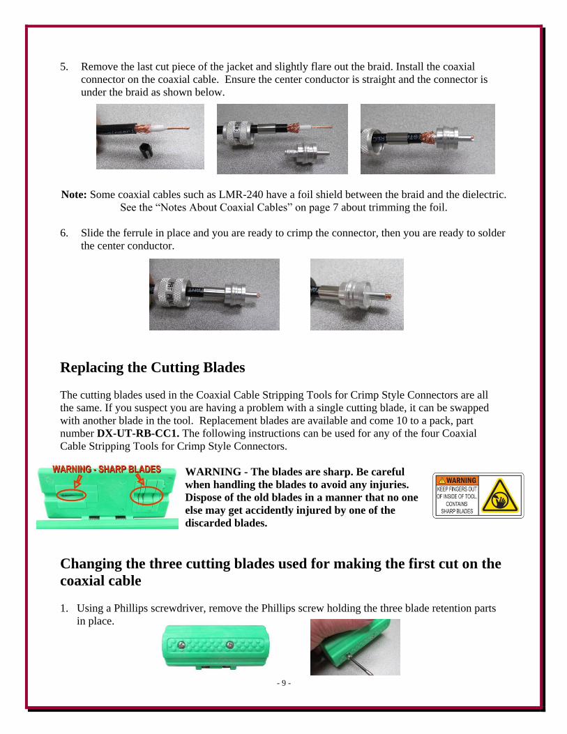
5. Remove the last cut piece of the jacket and slightly flare out the braid. Install the coaxial
connector on the coaxial cable. Ensure the center conductor is straight and the connector is
under the braid as shown below.
Note: Some coaxial cables such as LMR-240 have a foil shield between the braid and the dielectric.
See the “Notes About Coaxial Cables” on page 7 about trimming the foil.
6. Slide the ferrule in place and you are ready to crimp the connector, then you are ready to solder
the center conductor.
Replacing the Cutting Blades
The cutting blades used in the Coaxial Cable Stripping Tools for Crimp Style Connectors are all
the same. If you suspect you are having a problem with a single cutting blade, it can be swapped
with another blade in the tool. Replacement blades are available and come 10 to a pack, part
number DX-UT-RB-CC1. The following instructions can be used for any of the four Coaxial
Cable Stripping Tools for Crimp Style Connectors.
WARNING - The blades are sharp. Be careful
when handling the blades to avoid any injuries.
Dispose of the old blades in a manner that no one
else may get accidently injured by one of the
discarded blades.
Changing the three cutting blades used for making the first cut on the
coaxial cable
1. Using a Phillips screwdriver, remove the Phillips screw holding the three blade retention parts
in place.

- 10 -
2. Using the small Phillips screwdriver, you can gently push the internal parts loose and remove
the blade retainer parts from the tool.
3. When the retainer parts and blades are laid out, it looks like the picture below. Note: Each of
the retainer parts has a small square and number molded into the part for easier
assembly.
4. Starting with part number 1, insert the alignment pin and the first blade.
Note: The blade will only go in part number 1 one way (this is the same for all of
the blades and the other retainer parts as well).
5. Add part number 2 and a cutting blade to the stack.
6. Add part number 3 and a cutting blade to the stack.
7. Add part 4 to the stack. Gently pick up the stack and place it in the tool. Not the
alignment tab. The stack only goes into the tool one way. Gently push on the
stack to fully seat it in the tool. Be careful - sharp blades!
8. Replace the Phillips screw that held the stack in the tool.

- 11 -
Changing the cutting blade used for making the second cut on the
coaxial cable
1. Using a Phillips screwdriver, remove the Phillips screw holding the single blade retention parts
in place.
2. Using the small Phillips screwdriver, you can gently push the internal parts loose and remove
the blade retainer parts from the tool.
3. When the blade and retainer parts are laid out, it looks like the picture below.
4. Place the blade in place on the first part as shown. Note the blade will only go in one way.
5. Add the second retainer with the metal pin to the stack as shown.
6. Gently pick up the stack and place it in the tool. Note the way it is inserted into the tool. The
stack only goes into the tool one way. There is an alignment tab. Gently push on the stack to
fully seat it in the tool. Be careful - sharp blade!

- 12 -
8. Replace the Phillips screw that held the blade retainer parts in the tool.
Weatherproofing
Over the years many different methods have been used to weatherproof coaxial cable connections.
Some worked, some did not. Once water or condensation enters your coaxial cable, it will ruin the
coaxial cable or worse yet, cause shorting or high SWR conditions which could lead to permanent
damage to your transmitter.
One type of coaxial connector sealing material is a gummy tar like substance that you wrap around
the coaxial connector. This gummy substance works well, except when you try to remove it for
maintenance or coaxial cable replacement, it can cause further problems. The gummy substance just
doesn't come off cleanly and small bits of it may remain in the threads of PL-259's or SO-239's.
These small bits of material are mini-insulators, and could cause intermittent operation.
The method described here uses a combination of two types of tape which not only protect your
coaxial connection, but also allow easy removal for future maintenance.
The two products, available from DX Engineering, used are:
TES-2155 - 3M Temflex™ 2155 Rubber Splicing Tape.
Conformable self-fusing super stretchy rubber electrical insulating tape. It is designed for
low voltage electrical insulating and moisture sealing applications. For outdoor use, it
should be protected from UV deterioration with an overwrap of TES-06132
TES-06132 - Scotch® Super 33+.
Highly conformable tape for all weather applications. This tape provides flexibility and
easy handling for all around performance. It also combines PVC backing with excellent
electrical insulating properties to provide primary electrical insulation for splices up to
600V and protective UV resistant jacketing.
These tapes can be used indoors or outdoors. When used outdoors the temperature should be above
freezing, and if it's raining, keep the assembly you are wrapping covered and dry while applying the
tapes. Any airborne moisture such as fog, rain and snow may cause the tape to not stick properly, so
take adequate precautions to protect the assembly you are weatherproofing.
Additionally, the coaxial cable and connectors should be clean and free of any moisture, dirt or
other residues.

- 13 -
The only tool you will need for this procedure is a pair of
scissors. The following example uses two pieces of coaxial
cable with PL-259 connectors that are joined together with
a short UHF barrel connector. This same method may be
used on any connection you are weatherproofing.
A. Cut a piece of TES-2155 - 3M Temflex™ 2155 Rubber Splicing Tape long enough to complete
the job you are doing. If the length you cut is too short, that's okay. You can add more where
needed and it will not compromise the weatherproofing.
In this example a 15" length of the TES-2155 - 3M Temflex™
2155 Rubber Splicing Tape was used to weatherproof two PL-
259's tightly connected together with a short UHF barrel
connector.
B. The TES-2155 - 3M Temflex™ 2155 Rubber Splicing Tape has a
protective backing material so the tape will not stick to itself when on
the roll. As shown below, peel this protective backing off of the length
that you cut from the roll.
C. Starting at one end, hold the end of the cut length of TES-2155 - 3M
Temflex™ 2155 Rubber Splicing Tape in place about one inch before the
end of the PL-259 and stretch it out until the width of the tape is about 50%
as shown below.
Starting
Stretched while overlapping wraps
D. While keeping the TES-2155 - 3M Temflex™ 2155 Rubber Splicing
Tape stretched, wrap the tape around the assembly and overlap the
previous wrap by about 50%. Keep going until the complete assembly
is covered, and go an extra inch beyond. If the length you cut is too
short for the entire assembly, that's okay. You can add more starting
where the one piece ended (overlap it) and then continue on in the same
manner described above. This completes the first layer wrap. TES-2155 - 3M Temflex™ 2155
Rubber Splicing Tape requires an added wrap of TES-06132 - Scotch®
Super 33+ tape for UV
protection.
- 14 -
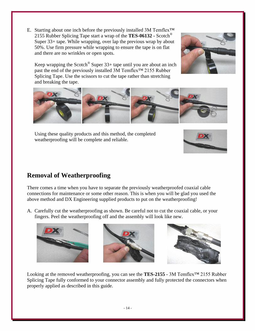
E. Starting about one inch before the previously installed 3M Temflex™
2155 Rubber Splicing Tape start a wrap of the TES-06132 - Scotch®
Super 33+ tape. While wrapping, over lap the previous wrap by about
50%. Use firm pressure while wrapping to ensure the tape is on flat
and there are no wrinkles or open spots.
Keep wrapping the Scotch®
Super 33+ tape until you are about an inch
past the end of the previously installed 3M Temflex™ 2155 Rubber
Splicing Tape. Use the scissors to cut the tape rather than stretching
and breaking the tape.
Using these quality products and this method, the completed
weatherproofing will be complete and reliable.
Removal of Weatherproofing
There comes a time when you have to separate the previously weatherproofed coaxial cable
connections for maintenance or some other reason. This is when you will be glad you used the
above method and DX Engineering supplied products to put on the weatherproofing!
A. Carefully cut the weatherproofing as shown. Be careful not to cut the coaxial cable, or your
fingers. Peel the weatherproofing off and the assembly will look like new.
Looking at the removed weatherproofing, you can see the TES-2155 - 3M Temflex™ 2155 Rubber
Splicing Tape fully conformed to your connector assembly and fully protected the connectors when
properly applied as described in this guide.

- 15 -
DX Engineering and Amphenol Connex coaxial cable crimp connectors
available from DX Engineering:
DXE-PL259CS8U-6/12/24 DX Engineering Next Generation Crimp/Solder UHF Male
Silver plated PL-259 body, solder center conductor, 50 ohm, PTFE dielectric, crimp
shield. For DXE-400 MAX, DXE-8U, DXE-RG-11/U, DXE-213U, RG-8/U, LMR-
400 type, most RG-213/U and equivalent coax cables with center conductors up to 10
AWG. Sold in packages of 6, 12 or 24.
AML-182102 Amphenol UHF Male Crimp Connector 182102
Silver plated nickel body, shell and center pin. 50 ohm. PTFE dielectric. Nickel plated
copper crimp ferrule. For some RG-8/U, most RG-213/U and equivalents with 12-13
AWG center conductors.
AMP-182130-10 Amphenol Connex UHF Male Crimp Connector 182130-10
Silver plated brass body, shell and center pin. Nickel plated copper crimp ferrule. 50
ohm. PTFE dielectric. Fits DXE-8U, DXE-400MAX, LMR-400 and equivalent cables
and RG-8U with 10-11 AWG center conductors.
DXE-PL259CS8X-6/12/24 DX Engineering Next Generation Crimp/Solder UHF Male
Silver plated PL-259 body, solder center conductor, 50 ohm, PTFE dielectric, crimp
shield. For DXE-8X, RG-8X, LMR-240 type and equivalent coax cables with center
conductors up to 10 AWG. Sold in packages of 6, 12 or 24.
AMP-182115-10 Amphenol Connex UHF Male Crimp Connector 182115-10
Silver plated brass body, shell and center pin, nickel plated copper crimp ferule. 50 ohm.
PTFE dielectric. For RG-8X, LMR-240 and equivalent cables.
AMP-172102 Amphenol Connex N-Type Male Crimp Connector 172102
White bronze finished brass with gold plated contact. PTFE dielectric. 50 ohm. For RG-8
(with 12-13 AWG center conductors), RG-213 and equivalents.
AMP-172102H243 Amphenol Connex N-Type Male Crimp Connector
White bronze finished brass with gold plated contact. PTFE dielectric. 50 ohm. For DXE-
400MAX, DXE-8U, RG-8 (with 10-11 AWG center conductors), LMR-400 and
equivalents.
AMP-172135 Amphenol Connex N-Type Male Crimp Connector 172135
Coaxial Cable Connector, Solderless crimp, PTFE dielectric. N Type Male for RG-8X,
LMR-240, 50 ohm.
AML-112533 Amphenol BNC Male Crimp Connector 112533.
Nickel finished brass with gold plated contact. Delrin dielectric. 50 ohm. For RG-8X,
LMR-240, and equivalents.

- 16 -
DX Engineering Crimp Tool Kit - DXE-UT-KIT-CRMP2
The DX Engineering Ultra-Grip 2 Crimp Connector Hand Tool Kit is ready for you to make professional quality
crimped coaxial cable assemblies, Powerpole® connectors and other popular size wire terminations.
The DXE-UT-CRMP2 Ultra-Grip 2 Crimp Connector Hand Tool is a quality ratcheting steel
crimper, ergonomically shaped for power, with soft non-slip dual color thermoplastic rubber
grips for comfortable and positive connector crimping results. The Ultra-Grip 2 Crimp
Connector Hand Tool is also made from high quality carbon steel with black oxide finish for
corrosion resistance and durability. The DXE-UT-CRMP2 Ultra-Grip 2 Crimp Connector
Hand Tool features high crimping quality that is repeatable with precision dies and their
integral locking mechanism.
The DX Engineering Ultra-Grip 2 Crimp Connector Hand Tool Kit, model DXE-UT-KIT-
CRMP2, provides a handsome, convenient carrying case furnished with the Ultra-Grip 2
Crimp Connector Hand Tool, cable cutting, braid snipping tool and all five crimp die sets
with a precut foam insert providing a home for each tool and die set. The coaxial cable
connector dies are designed to crimp the full ferrule and the center pin.
Guide Updates
Every effort is made to supply the latest guide revision. Occasionally a guide will be updated
between the time your DX Engineering product is shipped and when you receive it. Please check
the DX Engineering web site (http://www.dxengineering.com) for the latest revision guide.
Technical Support
If you have questions about these products, or if you experience difficulties during using these
instructions, contact DX Engineering at (330) 572-3200. You can also e-mail us at:
For best service, please take a few minutes to review this guide before you call.
Warranty
All products manufactured by DX Engineering are warranted to be free from defects in material and workmanship for a period of one (1) year from
date of shipment. DX Engineering’s sole obligation under these warranties shall be to issue credit, repair or replace any item or part thereof which is
proved to be other than as warranted; no allowance shall be made for any labor charges of Buyer for replacement of parts, adjustment or repairs, or
any other work, unless such charges are authorized in advance by DX Engineering. If DX Engineering’s products are claimed to be defective in
material or workmanship, DX Engineering shall, upon prompt notice thereof, issue shipping instructions for return to DX Engineering (transportation-
charges prepaid by Buyer). Every such claim for breach of these warranties shall be deemed to be waived by Buyer unless made in writing. The above
warranties shall not extend to any products or parts thereof which have been subjected to any misuse or neglect, damaged by accident, rendered
defective by reason of improper installation, damaged from severe weather including floods, or abnormal environmental conditions such as prolonged
exposure to corrosives or power surges, or by the performance of repairs or alterations outside of our plant, and shall not apply to any goods or parts
thereof furnished by Buyer or acquired from others at Buyer’s specifications. In addition, DX Engineering’s warranties do not extend to other
equipment and parts manufactured by others except to the extent of the original manufacturer’s warranty to DX Engineering. The obligations under
the foregoing warranties are limited to the precise terms thereof. These warranties provide exclusive remedies, expressly in lieu of all other remedies
including claims for special or consequential damages. SELLER NEITHER MAKES NOR ASSUMES ANY OTHER WARRANTY
WHATSOEVER, WHETHER EXPRESS, STATUTORY, OR IMPLIED, INCLUDING WARRANTIES OF MERCHANTABILITY AND
FITNESS, AND NO PERSON IS AUTHORIZED TO ASSUME FOR DX ENGINEERING ANY OBLIGATION OR LIABILITY NOT STRICTLY
IN ACCORDANCE WITH THE FOREGOING.
©DX Engineering 2017
DX Engineering®, DXE®, DX Engineering, Inc.®, Hot Rodz®, Maxi-Core®, DX Engineering THUNDERBOLT®, DX Engineering Yagi
Mechanical®, EZ-BUILD®, TELREX®, Gorilla Grip® Stainless Steel Boom Clamps, Butternut®, SkyHawk™, SkyLark™, SecureMount™,
OMNI-TILT™, RF-PRO-1B®, AFHD-4® are trademarks of PDS Electronics, Inc. No license to use or reproduce any of these trademarks or other
trademarks is given or implied. All other brands and product names are the trademarks of their respective owners.
Specifications subject to change without notice.