COAX INTERFACE - OKI Supportmy.okidata.com/idocs2.nsf/6f9a3c7aef0a3559852568eb0067da73... · For...
8
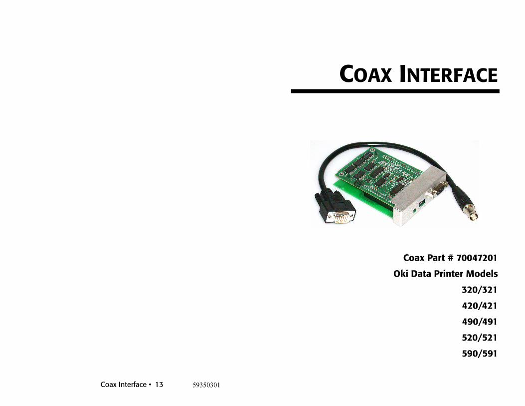
Coax Interface • 13 59350301 COAX INTERFACE Coax Part # 70047201 Oki Data Printer Models 320/321 420/421 490/491 520/521 590/591
Transcript of COAX INTERFACE - OKI Supportmy.okidata.com/idocs2.nsf/6f9a3c7aef0a3559852568eb0067da73... · For...
Coax Interface • 13 59350301
COAX INTERFACE
Coax Part # 70047201
Oki Data Printer Models
320/321
420/421
490/491
520/521
590/591

NOTICEThe information contained in this document is subject to change without notice.All trademarks, logos, and products mentioned are trademarks and/or registered trademarks of their respective owners.
This equipment has been tested and found to comply with the limits for a class A digital device, pursuant to Part 15 of the FCC rules and regulations. These rules are designed to provide reasonable protection against harmful interference when equipment is operated in a commercial environment. This equipment generates, uses, and can radiate radio frequency energy, and if not installed and used in accordance with the instruction manual, may cause harmful interference to radio communications. Operating this equipment in a residential area is likely to cause harmful interference in which case the user will be required to correct the interference at his or her own expense.
Coax Interface • 12
Coax Interface • 11
7. Support InformationFor specific questions regarding the Coax Interface only, please contact:
Troy Group, Inc.2331 South Pullman StreetSanta Ana, CA 92705Ph. 949-250-3280 or 800-332-6427 (U.S. Only)Fx. [email protected]
Table of Contents
General Information . . . . . . . . . . . . . . . . . . . . . . . . . . . . . . . . . . 1Introduction ........................................................................................ 1
Installation . . . . . . . . . . . . . . . . . . . . . . . . . . . . . . . . . . . . . . . . . 2Configuration . . . . . . . . . . . . . . . . . . . . . . . . . . . . . . . . . . . . . . . 4
Using Pass-thru Sequences................................................................. 4Features and Values............................................................................ 5
Operation . . . . . . . . . . . . . . . . . . . . . . . . . . . . . . . . . . . . . . . . . . 6ASCII Pass-thru.................................................................................. 6Diagnostics ......................................................................................... 7
Appendix A. . . . . . . . . . . . . . . . . . . . . . . . . . . . . . . . . . . . . . . . . 8EBCDIC Conversion Charts............................................................... 8
Appendix B . . . . . . . . . . . . . . . . . . . . . . . . . . . . . . . . . . . . . . . . 10Decimal/HEX Conversion Table...................................................... 10
Support Information . . . . . . . . . . . . . . . . . . . . . . . . . . . . . . . . . 11

Coax Interface • 1
1. General Information
1.1 IntroductionThis interface allows you to direct attach your Oki dot matrix printer to a coax host, providing EBCDIC to ASCII data stream translation.
The printer should be configured on the mainframe host as an IBM 3287.
Coax Interface • 10
6. Appendix B
6.1 Decimal/HEX Conversion TableThe numbers on the left represent the first HEX digit and the numbers at top represent the second hex digit. For example, to convert the value 137 to hex, find 137 in the table. The first HEX digit on the left row of the table is 8 and the second hex digit top row is 9 giving a HEX value of 89.
0 1 2 3 4 5 6 7 8 9 A B C D E F
0 0 1 2 3 4 5 6 7 8 9 10 11 12 13 14 15
1 16 17 18 19 20 21 22 23 24 25 26 27 28 29 30 31
2 32 33 34 35 36 37 38 39 40 41 42 43 44 45 46 47
3 48 49 50 51 52 53 54 55 56 57 58 59 60 61 62 63
4 64 65 66 67 68 69 70 71 72 73 74 75 76 77 78 79
5 80 81 82 83 84 85 86 87 88 89 90 91 92 93 94 95
6 96 97 98 99 100 101 102 103 104 105 106 107 108 109 110 111
7 112 113 114 115 116 117 118 119 120 121 122 123 124 125 126 127
8 128 129 130 131 132 133 134 135 136 137 138 139 140 141 142 143
9 144 145 146 147 148 149 150 151 152 153 154 155 156 157 158 159
A 160 161 162 163 164 165 166 167 168 169 170 171 172 173 174 175
B 176 177 178 179 180 181 182 183 184 185 186 187 188 189 190 191
C 192 193 194 195 196 197 198 199 200 201 202 203 204 205 206 207
D 208 209 210 211 212 213 214 215 216 217 218 219 220 221 222 223
E 224 225 226 227 228 229 230 231 232 233 234 235 236 237 238 239
F 240 241 242 243 244 245 246 247 248 249 250 251 252 253 254 255

Coax Interface • 9
LU3 to ASCII Conversion
0 1 2 3 4 5 6 7 8 9 A B
0 Sp 0 & a q A Q
1 EM — 1 - b r B R
2 FF ‘ 2 c s C S
3 NL “ 3 d t D T
4 / 4 e u E U
5 CR \ 5 f v F V
6 | 6 g w G W
7 | 7 h x H X
8 > ? 8 i y I Y
9 < ! 9 j z J Z
A [ $ ^ k K
B ] ~ l L
C ( # m M
D ) @ ` n N
E { % ‘ o O
F } _ p P
Coax Interface • 2
2. Installation
1. Power off the printer with which you will be attaching the interface. Damage can occur to the interface or printer if it is connected while printer power is on.
2. Remove the plastic punch out next to the parallel input connector on the printer and slide the interface into the expansion slot on the back of the printer.
Coax Interface • 3
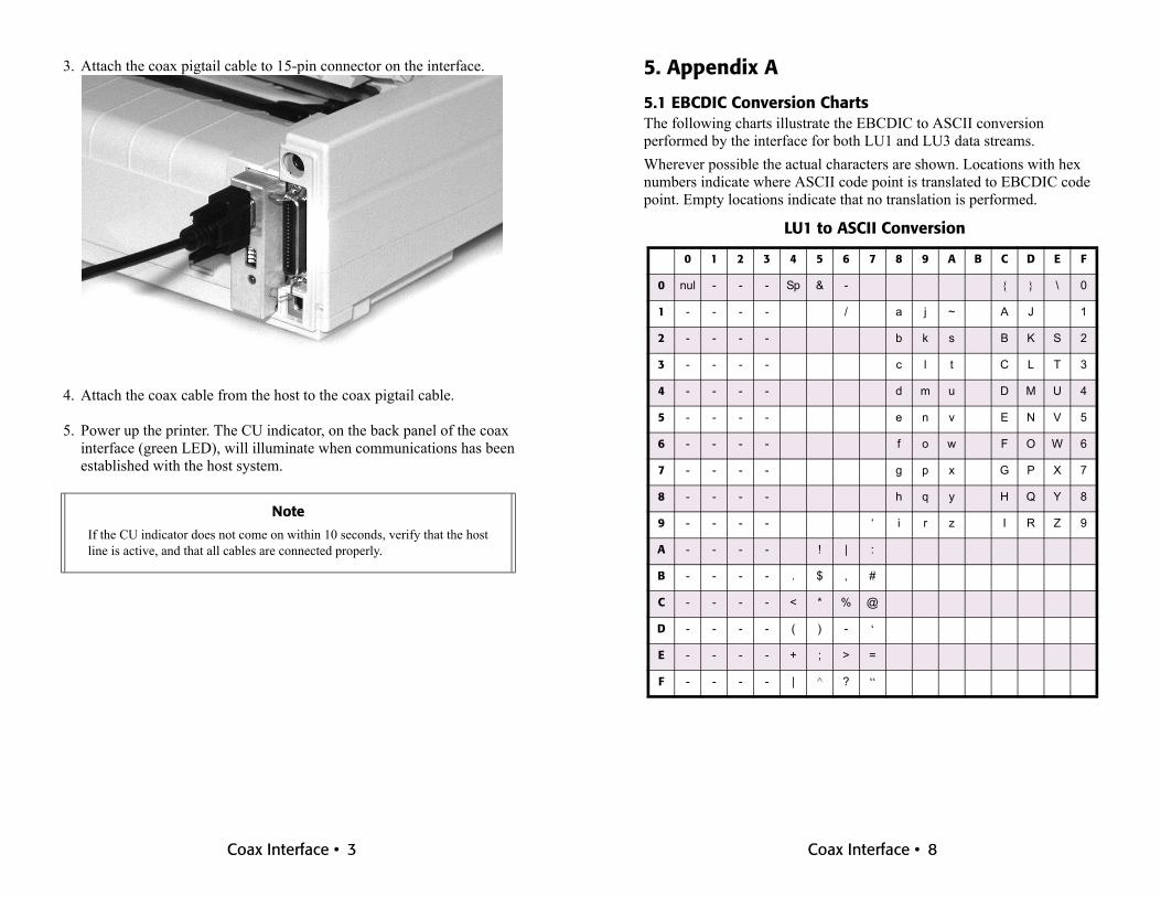
3. Attach the coax pigtail cable to 15-pin connector on the interface.
4. Attach the coax cable from the host to the coax pigtail cable.
5. Power up the printer. The CU indicator, on the back panel of the coax interface (green LED), will illuminate when communications has been established with the host system.
Note
If the CU indicator does not come on within 10 seconds, verify that the host line is active, and that all cables are connected properly.
Coax Interface • 8
5. Appendix A
5.1 EBCDIC Conversion ChartsThe following charts illustrate the EBCDIC to ASCII conversion performed by the interface for both LU1 and LU3 data streams.Wherever possible the actual characters are shown. Locations with hex numbers indicate where ASCII code point is translated to EBCDIC code point. Empty locations indicate that no translation is performed.
LU1 to ASCII Conversion
0 1 2 3 4 5 6 7 8 9 A B C D E F
0 nul - - - Sp & - { } \ 0
1 - - - - / a j ~ A J 1
2 - - - - b k s B K S 2
3 - - - - c l t C L T 3
4 - - - - d m u D M U 4
5 - - - - e n v E N V 5
6 - - - - f o w F O W 6
7 - - - - g p x G P X 7
8 - - - - h q y H Q Y 8
9 - - - - ‘ i r z I R Z 9
A - - - - ! | :
B - - - - . $ , #
C - - - - < * % @
D - - - - ( ) - ‘
E - - - - + ; > =
F - - - - | ^ ? “

Coax Interface • 7
4.2 Diagnostics
Print settingsSet dip-switches 1,2,3 to the ON position and then recycle power on the printer. The interface will print a test page with its current configuration settings.
EBCDIC Hex DumpSet dip switch 4 (only) to the ON position and then recycle power on the printer. Any data received will be printed in a formatted EBCDIC hex dump.
Coax Interface • 4
3. Configuration
3.1 Using Pass-thru SequencesThe interface can be configured by sending short pass-thru commands in the data stream indicating the feature to be changed and the value it is to have. This can be done by performing a local screen print, or the sequences can be embedded in a simple print file. The format for pass-thru mode is as follows:
&%SXXYYSXXYY..&%
Important!On-Line programming changes are stored temporarily in RAM memory and are not made permanent until the interface receives the command to do so. The following string makes configuration changes permanent.
(& % S 9 5 &%)
After all the necessary configurations have been made, it is a good idea to reset the printer so that both it and the interface will be in a known state.
&% Enters PassthroughS Indicates the start of a sequenceXX Is the feature number See “Features
and Values” on page 5YY Is the value of the feature&% Terminates Passthrough
Note• XX and YY are upper-case HEX digits. S is the upper-case “S”
character.• While in Pass-thru mode the interface does not check the feature
values to see if they are within the feature's range. It is up to the programmer to insure that only valid values are being sent.
• Once the interface receives the &% characters, it is no longer in pass-thru mode and will return to normal operation.
• When setting features, only hex values may be used! If you wish to set a value to decimal 35, you must use the hex value 23.
• See “Decimal/HEX Conversion Table” on page 10 for decimal to hex conversion table.

Coax Interface • 5
This can also be done by sending a "soft reset" command (&%S8F&%), which causes the interface to re-initialize.
3.2 Features and Values* Bold signifies default value for programmable features.
Note
After the interface has received a soft reset command, the device will drop communication with the host while the power up cycle is executing. It is recommended that on-line configuration be limited to initial set up or special files sent between print jobs.
Feature Description Values
02 Coax Printer Type 01 - 328702 - 3262
0E Lead-In Character PT#1 20 - FF38 (Hex 26) - &
0F Lead-In Character PT#2 20 - FF37 (Hex 25) - %
10 Ending Character PT#3 20 - FF38 (Hex 26) - &
1E NULs as spaces 01 - On02 - Off
21 TEXT only mode 01 - On02 - Off
8F Soft Reset none93 Load Factory Defaults none94 Print Status Page none95 Make config permanent none
Coax Interface • 6
4. Operation• Ensure all of the parameters have been set up properly, the
configuration has been made permanent, and the host cable is attached.
• Ensure the dip-switch is set to a value of “0,” which is all switches in the “OFF” position.
• Give the printer a fresh power up or send a soft reset command to re-initialize the interface. (& % S 8 F &%)
• The Cu indicator will illuminate when the host and the printer establish communications.
4.1 ASCII Pass-thruCommand Pass-Thru can be used to pass ASCII characters to the printer from an IBM twinax or coax host computer.Command Pass-Thru is character in nature, so you may send the data to the interface by executing a local copy or screen print from your twinax or coax host.The following characters can be sent:
decimal 0-9 (EBCDIC F0 - F9)or
characters A-F (EBCDIC C1- C6)All other characters will be ignored. This is a control measure, so that only valid characters and control codes can be sent.Here's an example of a proper Pass-Thru sequence that will send the ASCII ESCape character to the printer:
The lead-in and exit character values must match PT#1, PT#2 and PT#3 programmed during setup.
&%1B&%
&% The two lead-in characters (PT#1 & PT#2), and serve to place the interface into Pass-thru mode.
1B The two characters representing the ASCII ESCape character.
&% The exit code (PT#3) and informs the interface that pass-thru mode will terminate.