Coating Impact Fatigue Test - steel.org/media/Files/ASP/Enabling Programs/Tribology... · 1...
28
Transcript of Coating Impact Fatigue Test - steel.org/media/Files/ASP/Enabling Programs/Tribology... · 1...

Coating Impact Fatigue Test
Project: ASP230. Project No.: 10-2338
Phase II - Final Report
Prof. Xueyuan Nie PhD Student: Jun Feng Su
Mechanical, Automotive and Materials Engineering University of Windsor
Windsor, Ontario N9B 3P4 Canada
Prepared for: Tribology Team
Auto/Steel Partnership 2000 Town Center Drive
Suite 320 Southfield, MI 48075
USA
July 2010

ii
ACKNOWLEDGEMENT
Department of Energy Auto/Steel Partnership Chrysler LLC Ford Motor Company General Motors Arcelor Mittal Defasco Nucor Corporation Severstal North America, Inc. United States Steel Corporation Dayton Progress IonBond LLC Oerlikon Balzers VST, Inc. Richter Precision Inc.
USAMP/DOE: This material is based upon work supported by the Department of Energy National Energy Technology Laboratory under Award Number DE-FC-02OR22910. “This report was prepared as an account of work sponsored by an agency of the United States Government. Neither the United States Government nor any agency thereof, nor any of their employees, makes any warranty express or implied, or assumes any legal liability or responsibility for the accuracy, completeness, or usefulness of any information, apparatus, product, or process disclosed, or represents that its use would not infringe privately owned rights. Reference herein to any special commercial product, process, or service by trade name, trademark, manufacturer, or otherwise does not necessary constitute or imply its endorsement, recommendation, or favoring by the United States Government or any agency thereof. The views and opinions of authors expressed herein do not necessarily state or reflect those of the United States Government or any agency thereof.” A/SP: Further the project team also recognizes the support from the Auto/Steel Partnership and the research work conducted by the University of Windsor.

iii
EXECUTIVE SUMMARY
In order to effectively use physical and chemical vapor deposition (PVD/CVD) hard coatings as a solution in dealing with the die wear issues caused by stamping advanced high strength steel (AHSS), USAMP and the Auto/Steel Partnership granted a research project, entitled ”Coating Impact Fatigue Test” (Project: ASP230 No.: 09-2330 (Phase I) and No: 10-2338 (Phase II)), in which a new impact fatigue testing methodology has been successfully utilized to investigate coating failures and provide a better understanding of coating failure behavior.
This report documents the tasks accomplished in Phase II of the Coating Impact Fatigue Test project. Different from the test method used in Phase I, where the coating failures were studied using an impact tester without a sliding motion, an Extended Impact Fatigue Test (EIFT) containing combinations of impact and sliding movements were used in Phase II to simulate the operating conditions of stamping applications.
During Phase II, the EIFT has been conducted on six PVD/CVD coatings adhered to American Iron and Steel Institute (AISI) D2 substrate samples. The coatings were provided from three different coating suppliers. Steel balls were applied with an 80 N impact force and a 200 N pressing force in each cycle for 1,500 and 10,000 cyclic impacts on the coated D2 samples. After tests, the impact-sliding wear tracks on the coatings were observed using Scanning Electron Microscopy (SEM). The performances of the coatings were ranked according to their failure severity. Furthermore, three selected coatings were dissected using Electrical Discharging Machining (EDM) wire cutting in order to study the coating failure behavior at their cross-sections along the impact-sliding tracks. The experimental results showed that cohesive chipping, adhesive peeling, ball material transferring, and fatigue cracking occurred on the impact-sliding wear tracks of all the coatings after the tests. The CVD B_TiC coating was considered the best in resistance against impact-sliding fatigue wear, while B_CrN performed similarly well to A_TiAlN coating. The research results demonstrated that the testing methodology was effective and explicit in evaluation of CVD and PVD coating performance.
iv
ABSTRACT
In Phase II, the Extended Impact Fatigue Test (EIFT) was carried out using a new inclined impact-sliding tester to simulate stamping applications. The counter body was a steel ball which impacted and slid on PVD/CVD coatings. Six coatings were tested, and the impact-sliding wear tracks on the coatings were observed using Scanning Electron Microscopy (SEM). The performances of the coatings were ranked according to their failure severity. Three coatings were selected and dissected using Electrical Discharging Machining (EDM) wire cutting in order to study the coating failure behavior at cross-sections along the impact-sliding wear tracks. The experimental results showed that all chipping, peeling, ball material transfer, and fatigue cracks could be observed in the impact-sliding wear tracks on the coatings. While the CVD B_TiC coating was considered the best in resistance against impact-sliding fatigue wear, B_CrN performed similarly well to A_TiAlN coating. The research results demonstrated that the testing methodology was effective and explicit in evaluation of PVD and CVD coating performance under impact/sliding wear conditions.

v
TABLE OF CONTENT
1. Introduction 1 2. Test Instrument 1 3. Results 2
3.1 Nanoindentation Tests 2 3.2 Inclined Impact Fatigue Test 4
3.2.1 Impact and Pressing Force Loading Curve 4 3.2.2 Typical Failure Modes 4 3.2.3 Experimental Results 5
3.2.3.1 Tests with Steel Balls and 1500 Cycles 5 3.2.3.2 Tests with Steel Balls and 10000 Cycles 11
3.2.3.3 Cross sections of Selected Impact-sliding Tracks 12 3.3 Ranking of Coatings 19
4. Conclusions in Phase II 20

vi
List of Figures
Figure 1: Schematic of an inclined impact-sliding wear tester 2 Figure 2: Berkovich hardness of different coatings (Phase I & II) 3 Figure 3: Elastic modules of different coatings (Phase I & II) by nanoindentation 3 Figure 4: A typical impact cycle at 5 Hz impact frequency 4 Figure 5: SEM images and illustration of failure modes 5 Figure 6: SEM images of the impact-sliding track of A_TiAlN after 1500 cycles with a steel ball 6 Figure 7: SEM images of the impact-sliding track of B_TiAlN after 1500 cycles with a steel ball 7 Figure 8: SEM images of the impact-sliding track of A_CrN after 1500 cycles with a steel ball 8 Figure 9: SEM images of the impact-sliding track of B_CrN after 1500 cycles with a steel ball 9 Figure 10: SEM image of the impact-sliding track of B_TiC after 1500 cycles with a steel ball 10 Figure 11: SEM images of the impact-sliding track of C_TiC after 1500 cycles with a steel ball 10 Figure 12: SEM images of the impact-sliding track of B_TiC after 10000 cycles with a steel ball 11 Figure 13: Summary of the impact-sliding tracks of six coatings after 1500 cycles with steel balls 12 Figure 14: Overall SEM image of the cross section of the B_CrN impact-sliding track after 13
1500 cycles’ test using a steel ball Figure 15: Local views of the cross section in Figure 14 14 Figure 16: Overall SEM image of the cross section of the A_TiAlN impact-sliding track after 16 1500 cycles’ test using a steel ball Figure 17: Local views of the cross section in Figure 16 16 Figure 18: Overall SEM image of the cross section of the B_TiC impact-sliding track after 17 10000 cycles’ test using a steel ball Figure 19: Local views of the cross section in Figure 18 18

vii
List of Tables
Table 1: Ranking of coating failures in inclined impact-sliding wear tests using steel balls 19

1
”Coating Impact Fatigue Test” Phase II
1. Introduction
Impact fatigue testing methodology has been developed and used to study coating failure behavior under vertical impacting motions in Phase I. Experiments and FEM analyses of this vertical ball-on-plate impact fatigue tests have been performed on six samples. All six coated samples showed good adhesion to their substrate. However, depending on coating materials and even the same coating materials but from different coating suppliers, the coatings performed differently in severity of cohesive chipping, adhesive peeling, ball material transfer, and fatigue cracking. Since stamping likely includes not only impacting but also sliding motions, an Extended Impact Fatigue Test (EIFT) was used to simulate the impact-sliding wear conditions in Phase II of the project. In the period of Phase II, six coatings provided from A/S P were tested. Steel balls were used as the impacting and sliding counter materials. The impact-sliding wear tracks on the coatings were studied using Scanning Electron Microscopy (SEM) and Energy Dispersive X-ray analysis (EDX). The performance of the coatings was ranked according to their failure severity. Also, three selected coatings were dissected using Electrical Discharging Machining (EDM) wire cutting to show the coating failure behavior at the cross sections along the impact-sliding tracks. Failure mechanisms of the three coatings were then discussed. This report is to present the research results obtained in Phase II, the second part of the project Coating Impact Fatigue Test funded by Auto/Steel Partnership through USAMP/DOE. 2. Test Instrument
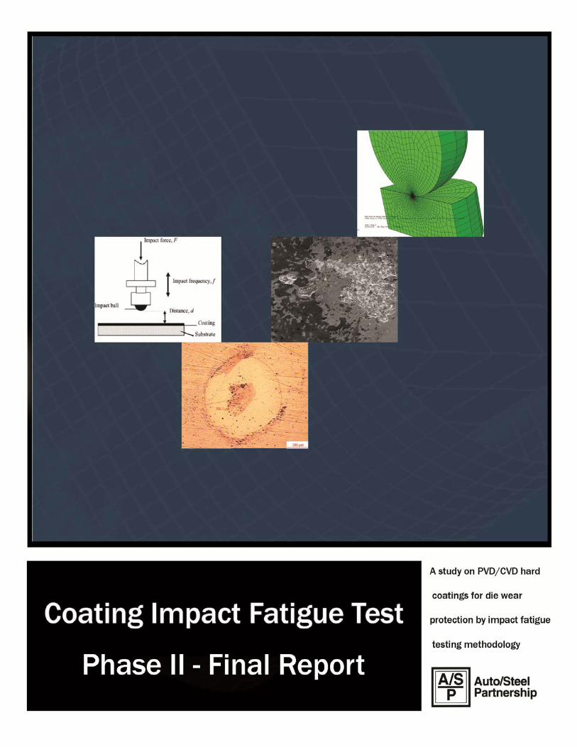
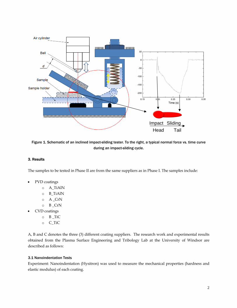
A schematic drawing of the inclined impact-sliding tester used in Phase II of this project is shown in Figure 1. During the inclined impact-sliding fatigue test, a hard ball (the impact body) is mounted on the shaft of a double-way air cylinder with the piston driven by compressed air producing vertical oscillatory motions. The sample is set on an inclined rotary sample holder which can return its position by a spring. An OMEGA LCKD-500 load cell is placed on the sample holder to record the normal force on the sample surface during the impact-sliding movement. To reduce friction, a thin layer of lubricant is applied on the load cell surface. The desired normal impact and pressing forces are obtained by adjusting the pre-strain of the spring and the pressure in the air cylinder. For all the tests in Phase II, the impact and pressing loads were set as 80 N and 200 N, respectively. After the impact/pressing forces are measured and recorded, the load cell is removed and coated samples are placed on the sample holder for impact tests. The distance d between ball and the sample needs to be the same as the previous distance between the load cell and the ball. In Phase II, each coated sample was scheduled to be impacted 1500 cycles or 10000 cycles. After the test, a crater head and a sliding wear track appeared on the coating surface as illustrated in Figure 1.
2
Figure 1. Schematic of an inclined impact-sliding tester. To the right, a typical normal force vs. time curve
during an impact-sliding cycle.
3. Results
The samples to be tested in Phase II are from the same suppliers as in Phase I. The samples include:
PVD coatings o A_TiAlN o B_TiAlN o A _CrN o B _CrN
CVD coatings o B _TiC o C_TiC
A, B and C denotes the three (3) different coating suppliers. The research work and experimental results obtained from the Plasma Surface Engineering and Tribology Lab at the University of Windsor are described as follows: 3.1 Nanoindentation Tests
Experiment: Nanoindentation (Hysitron) was used to measure the mechanical properties (hardness and elastic modulus) of each coating.
Head Tail
Sliding Impact

3
Results: Hardness and elastic modulus with comparison between Phase I and Phase II are presented in Figure 2 and Figure 3, respectively. Big differences in hardness and elastic modulus between Phase I and Phase II appear in the B_TiAlN coatings. Similar to the cases in Phase I, hardness and elastic modulus of coatings from different suppliers are quite different. A_TiAlN and B_TiC coatings have the highest hardness. Again, the hardness and elastic modulus of C_TiC are low. The low hardness and elastic modulus values of C_TiC coating are likely due to the two-layer coating structure which has a softer top layer, possibly caused by the coating heat treatment.
Figure 2: Berkovich hardness of different coatings (Phase I & II). A, B and C denotes different suppliers respectively
Figure 3: Elastic modulus of different coatings (Phase I & II) by nanoindentation
TiAlN TiAlN CrN CrN TiC TiC0
5
10
15
20
25
30
35
C
B
B
A
Har
dnes
s (G
Pa)
Phase I Phase IIA B
TiAlN TiAlN CrN CrN TiC TiC0
50
100
150
200
250
300
350
400
450
Ela
stic
Mod
ulus
(G
Pa)
Phase I Phase II
B
A
A
BB
C

4
3.2 Inclined Impact Fatigue Test
3.2.1 Impact and Pressing Force Loading Curves
Experiment: A selected test loading condition (i.e., 80 N impact force and 200 N pressing force) and hardened SAE 51000 steel balls (10mm in diameter) were used for the inclined impact-sliding fatigue tests. Coating failure mechanisms were investigated for the different coatings that were tested at the same conditions above. The impact frequency, f, and ball to sample distance, d, were set at 5 Hz and 1 mm, respectively, in all tests and the static air pressure, P, was set around 0.11 MPa. Thus, the maximum impact force was 80 N and pressing forces 200 N, determined by an OMEGA LCKD-500 load cell measurement. The impact and pressing force loading curves were recorded by a KYOWA PCD-300A Sensor Interface System. A typical load cycle is presented in Figure 4.
Figure 4: A typical load cycle at 5 Hz impact frequency
3.2.2 Typical Failures
In Phase II, there were still 4 primary failure mechanisms as in Phase I, namely, - cohesive failures (mainly chipping), - adhesive failures (mainly peeling), - material transfer, and - fatigue cracks.
A schematic of these failures is given in Figure 5. The characterization of failure modes was based on the EDX analysis method as used in Phase I. All the coating failure mechanisms mentioned above could be observed in most cases. Fatigue cracks may be the main reason for the coatings to initiate cohesive and adhesive failures. For example, fatigue cracks may lead to chipping (cohesive failure) and peeling
Impact force
Pressing force

5
(adhesive failure). Material transfer may be more severe at the spot where the surface became rough due to other failures. The locations where cohesive and adhesive failures occur may also in return act as initiation sites of fatigue cracking and as a result, the chipping and peeling areas increased at a fast path.
Figure 5: SEM images and Illustration of failure modes
3.2.3 Experimental Results
Samples were subjected to impact testing under unlubricated conditions. The impact balls were changed after each sample was tested. After the tests, the samples were observed and analyzed using a SEM with EDX to investigate coating failure behavior. Therein, the test results were summarized after the following test conditions:
- Tests with Steel Balls and 1500 Cycles - Tests with Steel Balls and 10000 Cycles
3.2.3.1 Tests with Hardened SAE 52100 Steel Ball, 1500 cycles
The A_TiAlN coating displayed all four primary failure mechanisms as shown in Figure 6. Peeling with surrounding chipping and fatigue cracks were found at the impact-induced crater. The TiAlN coating materials still existed at the center of the crater with Fe transferred from the steel ball. Fatigue cracks appeared at the boundary of the crater and along most of the sliding track as shown in Figure 6b and Figure 6c.
Peeling Chipping Material Transfer Fatigue Cracks (Diffusion/Accumulation)
Coating
Substrate

6
Figure 6: SEM images of the impact-sliding track of A_TiAlN after 1500 cycles (a) Overview; (b) fatigue cracks at the edge of the crater; (c) fatigue cracks in the sliding track
Although the hardness and elastic modulus of the B_TiAlN sample were lower in Phase II than in Phase I, B_TiAlN acted similarly to its counterpart in Phase I which showed low resistance to impact and sliding of steel ball (Figure 7) compared with A_TiAlN. Cohesive failure zones formed at the center of the crater and along the sliding track. EDX analysis also showed the material transfer from the steel ball occurred (dark area in the impact-sliding track). Fatigue cracks and chippings were found around the track (Figures 7b and 7c).
(a)
(b) (c)
Chipping
Fatigue cracks
Peeling Material transfer on remained coating
Material transfer
Fatigue cracks
Fatigue cracks

7
Figure 7: SEM images of the impact-sliding track of B_TiAlN after 1500 cycles (a) Overview; (b) local view showing fatigue cracks; (c) chipping; (d) material transfer
Two CrN samples tested after 1500 cycles are presented in Figure 8 and Figure 9. The coating in the crater of the A_CrN disappeared and the substrate was exposed (Figure 8a). Fatigue cracks were found around the head of the crater. The A_CrN coating material still remained in the area between the crater and the tail of the track with some Fe transferred from the steel ball. Figure 8b shows fatigue cracks around the failure area of the crater head, and Figure 8c illustrates chipping and peeling failures at the tail area of the sliding track.
Fatigue cracks Material transfer Chipping(b) (c) (d)
Chipping
Fatigue cracks
Peeling
Material transfer on remained coating
(a)

8
Figure 8: SEM images of the impact-sliding track of A_CrN after 1500 cycles (a) Overview; (b) local view showing fatigue cracks; (c) tail of the track
B_CrN performed better than A_CrN in the steel ball impact-sliding test. The dark areas in the crater shown in Figure 9a contained Fe transferred from the steel ball during the impact. Fatigue cracks and chipping were found at the top head of the crater (Figure 9b) and also at the middle head of the crater (Figure 9c). Although most coating materials remained in a good shape on the sliding track, it was also found that chipping occurred at both the tail and the track (Figure 9d). Material transfer from the steel ball also appeared on the surface of the remained coating in the wear track.
Chipping + Peeling
Fatigue cracks (a)
(b) (c)
Fatigue cracks
Material transfer on remained coating

9
Figure 9: SEM images of the impact-sliding track of B_CrN after 1500 cycles (a) Overview; (b) local view showing fatigue cracks and peeling; (c) fatigue cracks and chipping; (d)
chipping
SEM images of TiC samples tested after 1500 cycles are shown in Figure 10 and Figure 11. B_TiC performed well like its counterpart in Phase I. Only material transfer and small chippings were found after the test of 1500 cycles (Figure 10). Figure 11 shows the impact-sliding track of the C_TiC coating with occurrence of localized peeling, chipping, material transferring and fatigue cracking. Material transfer occurred on the remained TiC coating and along the track.
Chipping
Fatigue cracks
Peeling Material transfer on
remained coating
(a)
(b) (c) (d)

10
Figure 10: SEM image of the impact-sliding track of B_TiC after 1500 cycles
Figure 11: SEM images of the impact-sliding track of C_TiC after 1500 cycles (a) Overview; (b) local view showing fatigue cracks; (c) material transfer
Chipping Material transfer
Peeling + ChippingFatigue cracks
Peeling
Material transfer on remained coating
(a)
(b)
Fatigue cracks
Material transfer on remained coating
(c)

11
3.2.3.2 Tests with Hardened SAE 52100 Steel Balls, 10000 cycles
Since the B_TiC coated sample showed the least failures during the 1500 cycles’ tests, an impact test up to 10000 cycles was also conducted on the sample to study the high cyclic test effect on impact fatigue of the B_TiC coating. After 10000 cycle impact test, most TiC coating materials in the crater disappeared, Figure 12a. Peeling, material transfer and fatigue cracks exhibited on the impact crater area, Figure 12b, while only chipping and material transfer were shown on the sliding track area, Figure 12c.
Figure 12: SEM images of the impact-sliding track of B_TiC after 10000 cycles (a) Overview; (b) local view showing fatigue cracks; (c) chipping
Chipping
Fatigue cracks
Peeling
Material transfer
(a)
Chipping
(b) (c)

12
Summary for steel ball impact-sliding tests
All impact-sliding tracks of six coatings are summarized in Figure 13 which shows the failure severity of different coatings in comparison. From these images, ranking their performance in the test conditions becomes possible.
Figure 13: Summary of the impact-sliding tracks of six coatings after 1500 cycles using steel balls
(aspect ratio is not accurate)
3.2.3.3 Cross section of selected impact-sliding tracks
Cross sectioning was used to study the fatigue crack propagation and failure mechanisms of coatings. Although transmission electron microscopy (TEM) was originally proposed to be used in investigation of the coating failures in the thickness direction, preparations of TEM specimen from areas around the craters and along the long wear tracks of the coatings were found to be real time and money consuming. Every coating would need at least 10 TEM specimens. Each specimen can only be prepared using a Focus Ion Beam (FIB) instrument. An alternative method was figured out at the late stage of Phase II. That is, Electrical Discharging Machining (EDM) wire cutting were used to dissect the coatings along impact-sliding wear tracks first, then SEM was used to observe the coating failure behavior along the cross sections and the top surfaces of the impact-sliding tracks.
A number of SEM images were taken on the cross sections of coatings, which provided valuable information from micrometer scale up to millimetre scale, contrary to nano- and micro-scales of TEM.
A-CrN
A-TiAlN B-CrN
B-TiAlN B-TiC
C-TiC

13
From the images, an overall view of impact-sliding wear track could be constructed and used to illustrate coating failures. There were three kinds of coating materials. TiAlN, CrN and TiC used in this project. For each kind of the coating materials, two coatings were deposited, from which the one with better performance was selected for dissection. Therefore, coatings of B_CrN 1500 cycles, A_TiAlN 1500 cycles and B_TiC 10000 cycles were chosen to be cut along the trail of the impact-sliding tracks using EDM wire cutting. The cross sections were then mechanical polished and observed using SEM. Cross sections of B_CrN impact-sliding track are presented and described in Figure 14 and Figure 15.
Figure 14: Overall SEM image of the cross section of the B_CrN impact-sliding track after 1500 cycles using a steel ball
p o n m l k j i h g
f ed c ar q b

14
(a)
(l)(k)(j)
(i)(h)(g)
(f)(e)(d)
(c)(b)
(m) (n) (o)

15
Figure 15: Local views of the cross section in Figure 14: (a) chipping at the edge of the crater; (b) EDX spectrum showing inexistence of CrN coating; (c) fatigue cracks around the crater; (d) EDX spectrum showing
Fe transferred from the steel ball to the remained coating; (e) composition of the CrN coating; (f) fatigue cracks at the head of the crater; (g) EDX spectrum showing the existence of CrN coating; (h) fatigue cracks at the cross section; (i) coating remained near the head; (j) deformed substrate without coating; (k) the end of
the crater; (l) chipping; (m) fatigue cracks along the impact-sliding track with a porous oxide layer which might be caused by EDM wire cutting; (n) a defect in substrate; (o) EDX spectrum showing composition of the
substrate; (p) intact coating; (q) chipping at the track; (r) peeling and material transfer
Based on the information in Figure 14 and Figure 15, the failure of the B_CrN coating may follow the sequences as: 1. Fatigue cracks occurred at the center of the crater and reached the substrate during the initial stage of
impact-sliding; 2. Cracked CrN coating separated from substrate piece by piece when the adjacent cracks are crossover in
near horizontal directions and was brought away by abrasive wear from the center of the crater; 3. The separation of small pieces from the CrN coating propagated outward during the following cycles
and formed the jagged steps around the crater except the end part of the crater; 4. At the end of the crater, shear stress began to dominate due to the sliding movement and led to both
the fatigue cracks and chipping (the tail part of the crater in Figure 14); 5. The shear stress continued to increase due to the increasing of the pressing load (up to 200 N) during
the sliding procedure and produced more chippings along the track (Figure 15l and 15q); with the increasing of the shear stress, peeling also happened (Figure 15r).
However, chipping might initiate from coating defects and not always occur right at the tail of the track, where the pressing load was the maximum (200 N) but the shear stress was low due to no inclined sliding force involved in this position. A cross section of A_TiAlN impact-sliding track was cut form the A_TiAlN coating. But this wear track was less damaged than the one shown in Figure 6. This would allow us to clearly observe coating failure processes at the interface between the coating and substrate and fatigue cracks within the coating. The cross section is presented and described in Figure 16 and Figure 17.
(p) (q) (r)Chipping
Peeling
Material transfer

16
Figure 16: Overall SEM image of the cross section of the A_TiAlN impact-sliding track after 1500 cycles using a steel ball
Figure 17: Local views of the cross section in Figure 16: (a) sinking of fatigue crack layers at the head of the crater; (b) interlaced TiAlN coating and Fe substrate; (c)peeling and chipping; (d) material transfer
and fatigue cracks; (e) crack and debonding of TiAl interface/bonding layer, needlelike islands in substrate are Cr-rich intermetallic phase; (f) fatigue cracks at the center of the track and TiAl interface/bonding layer;
(g) surface defects; (h) tail of the track showing fatigue cracks
a d f g e h b c
(a)
(f)(e)(d)
(c)(b)
(h) (g)
TiAlN
TiAlN Fe
Peeling
Chipping
Material transfer
Fatigue cracks
TiAl bonding layer
Fatigue cracks

17
Like B_CrN, jagged steps were found around the crater on the A_TiAlN sample. Contrary to B_CrN, cracked A_TiAlN coating pieces sunk into the substrate segment by segment (Figure 17a) and formed interlaced mixture (Figure 17b) during the impacts. Such a sinking phenomenon did not appear in B_CrN coating. Furthermore, the substrate was less exposed on A_TiAlN coating than on B_CrN coating after the tests (Figure 6 vs. Figure 9). These two different behaviors of the coatings may be explained by the fact that the A_TiAlN coating had high hardness and elastic modulus compared to B_CrN. For both of the coatings, fatigue cracks reached the substrate and spread along the entire sliding track. However, the fatigue cracking was more intense for A_TiAlN coating. Also, coating defects such as cracks in the coating bonding layer were usually related to the underlying Cr-rich intermetallic phase (Figure 17e). This phenomenon was found in all the three coatings. B_TiC under the 1500 cycles’ impact-sliding showed no severe failures. Therefore, the track of B_TiC tested with 10000 cycles was cut and presented and described in Figure 18 and Figure 19.
Figure 18: Overall SEM image of the cross section of the B_TiC impact-sliding track after 10000 cycles using a steel ball
c b a
de f ghi j k

18
Figure 19: Local views of the cross section in Figure 18: (a) EDX spectrum showing the dominance of TiC with little amount of Fe transferred from the steel ball; (b) EDX spectrum showing that Fe from the substrate dominated and TiC still existed; (c)EDX spectrum showing nonexistence of TiC ; (d) SEM image showing
fatigue cracks stopped in the middle of the coating; (e) remained TiC coating at the center of the crater; (f) end of the crater showing sinking of the coating; (g) chipping; (h) chipping; (i) surface defects and underlying
Cr-rich intermetallic phase; (j) scratches and chipping at the tail of the track; (k) cross section of intact coating showing the porous structure of the CVD B_TiC coating
The porous structure of the CVD B_TiC coating seemed to contribute to the best performance among the three coatings. Only small chippings and material transfer occurred after impacts of 1500 cycles. The cross section of the coating after 10000 cycles’ test shows that the propagation of fatigue cracks might be
(a) (c)(b)
(f)(e)(d)
(k) (j)
(i)(h)(g)
Remained TiC
Fatigue cracks

19
stopped by small holes in the coating. With the increasing of impact cycles, abrasive wear occurred and the coating disappeared at the center of the crater. Similar to the other two coating samples, chipping appeared from the crater to the end of the track. Again, the defects shown in bright areas of Figure 19i might be caused by the interaction of the Cr-rich intermetallic phases and coating materials during the coating fabrication process.
3.3 Ranking of coatings
The coating failure behaviors were described using the possible failure sequences presented in the previous section. In general, all kinds of failures occur at the crater center; chipping/peeling occur near the end of the track. With the increasing of impact cycles, failure areas at the crater and along the sliding track become larger and connect to each other to form the final shape as illustrated in Figure 1. Based on those observations, the performances of different coatings against steel balls are distinguished and evaluated as in Table 1. From Table 1, B_TiC is the best coating under the condition of the inclined impact-sliding fatigue testing.
Coatings Head
(impact)
Middle
(sliding)
Tail
(sliding)
Subtotal
(impact)
Subtotal
(sliding)
Subtotal
(fatigue) Total
Rank
(impact)
Rank
(sliding)
Rank
(fatigue)
Rank
(overall)
A_TiAlN xx/xxx/x* o/xx/o x/x/x 2/3/1
(6)
1/3/1
(5) 6 11 3 2 6 3
B_AlTiN xxxxx/xx/x xxxx/xx/xx xxxx/o/x 5/2/1
(8)
8/2/3
(13) 4 21 6 6 5 6
A_CrN xxxx/xxx/o xx/o/x xxxx/o/o 4/3/0
(7)
6/0/1
(7) 3 14 5 5 3 5
B_CrN xxx/xx/x x/o/o xx/x/x 3/2/1
(6)
3/1/1
(5) 3 11 3 2 3 3
B_TiC x/x/x x/o/x x/o/x 1/1/1
(3)
2/0/2
(4) 1 7 1 1 1 1
C_TiC xx/xx/o x/o/o xxx/o/xx 2/2/0
(4)
4/0/2
(6) 2 10 2 3 2 2
Table 1: Ranking of coating failures in inclined impact-sliding tests using steel balls. *Note: (peeling + chipping) / fatigue crack/ material transfer: (xxx)/(xxx)/(xxx)
Key: X: severity, O: N/A. Note: impact-induced failures at the head of the impact-sliding wear track
Note: sliding-induced failures at the sliding (middle and tail) portion of the impact-sliding wear track Note: fatigue failures occurred at the head, middle and tail portions of the wear track

20
4. Conclusions in Phase II
Inclined impact-sliding fatigue testing methodology and cross-sectioning technique using EDM cutting were used to study coating failure behavior under the test conditions representative of stamping applications. Experiments of ball-on-plate inclined impact-sliding fatigue tests (i.e. EIFT) have been performed on six coating samples. After the tests, peeling, chipping, fatigue cracking, and ball material transfer appeared in the impact-sliding wear trails, which can be clearly observed from the sample surface and cross sections. The research results demonstrated that the testing methodology was effective and explicit in evaluation of PVD and CVD coating performance under impact and sliding load conditions. The findings derived from the testing method for the six coatings were summarized as follows. After EIFT tests, a large number of fatigue cracks can be observed on A_TiAlN and B_CrN coating surfaces, most of which connected to the interface next to the D2 substrate. For A_TiAlN coating, fatigue cracking appeared along the entire impact-sliding trail, and local substrate deformations can be seen in the impact crater where the fatigue cracks occurred. For B_CrN coating, the enlarged crater size, compared to that of A_TiAlN coating, was likely due to the impact ball’s flattened surface, caused by abrasive wear from debris of the peeled and chipped coating. Less fatigue cracking and peeling was found on B_TiC coating after 1,500 test cycles. At 10,000 cycles, there was more chipping and peeling. The CVD B_TiC coating was considered the best, and B_CrN performed similarly well to A_TiAlN coating. Although A_TiAlN seems slightly better than B_CrN at 1,500 cycles, it exhibited more fatigue cracking than B_CrN.