Coastal Structure Underwater Inspection...
7
Suppl 8 (1998) Coastal Applications 1 REMR Technical Note CO-SE-1.5 Coastal Structure Underwater Inspection Technologies Purpose To introduce multibeam sonar technology for use in performing high- resolution, quantitative surveys of coastal structures. Background Most damage to coastal structures, especially rubble-mound breakwaters and jetties, occurs to the underwater portion of the structure. Underwater damage such as scour, settlement, and scattering and breakage of armor units is not often exhibited on the surface, and damage can progress until a major structural collapse occurs. Detection of underwater damage and deterioration is cost effective for coastal engineers in terms of planning for structure repairs and rehabilitation and for management of coastal structures over their lifetimes. Diver inspections provide some information about the condition of underwater structures, but these surveys are often difficult and risky, hampered by the normal occurrence of waves, currents, and limited visibility around the structure. The information obtained from diver surveys is subjective, and spatial detail is sparse. Additionally, results from side-scan sonars (SSS), a viable tool for structural surveys (Kucharski and Clausner 1990), are semi-quantitative and often distorted because of energetic wave and current conditions around the structure. In response to a need for objective, detailed, and quantitative definition of the underwater shape of coastal structures, initial REMR research conducted at the U.S. Army Engineer Waterways Experiment Station (WES) focused on hardware identification, evaluation, and prototype design. This research resulted in development of the Coastal Structure Acoustic Raster Scanner (CSARS) system. Since 1991, REMR investigations in this problem area have focused on developing hardware and software tools to inspect underwater portions of irregular, rubble-mound coastal structures. The CSARS system is a remote, bottom-deployed system consisting of a tripod containing a pointable 300-kHz acoustic transducer unit with driving motors and sensors (Figure 1). The CSARS tripod is cabled to an operator- controlled shipboard computer system that allows for real-time graphical display and onsite data postprocessing. The device has performed successfully in field
Transcript of Coastal Structure Underwater Inspection...
Suppl 8 (1998)
Coastal Applications 1
REMR Technical Note CO-SE-1.5
Coastal Structure Underwater Inspection Technologies
Purpose
To introduce multibeam sonar technology for use in performing high-resolution, quantitative surveys of coastal structures.
Background
Most damage to coastal structures, especially rubble-mound breakwaters andjetties, occurs to the underwater portion of the structure. Underwater damage suchas scour, settlement, and scattering and breakage of armor units is not oftenexhibited on the surface, and damage can progress until a major structuralcollapse occurs. Detection of underwater damage and deterioration is costeffective for coastal engineers in terms of planning for structure repairs andrehabilitation and for management of coastal structures over their lifetimes.
Diver inspections provide some information about the condition of underwaterstructures, but these surveys are often difficult and risky, hampered by the normaloccurrence of waves, currents, and limited visibility around the structure. Theinformation obtained from diver surveys is subjective, and spatial detail is sparse.Additionally, results from side-scan sonars (SSS), a viable tool for structuralsurveys (Kucharski and Clausner 1990), are semi-quantitative and often distortedbecause of energetic wave and current conditions around the structure.
In response to a need for objective, detailed, and quantitative definition of theunderwater shape of coastal structures, initial REMR research conducted at theU.S. Army Engineer Waterways Experiment Station (WES) focused on hardwareidentification, evaluation, and prototype design. This research resulted indevelopment of the Coastal Structure Acoustic Raster Scanner (CSARS) system.Since 1991, REMR investigations in this problem area have focused ondeveloping hardware and software tools to inspect underwater portions ofirregular, rubble-mound coastal structures.
The CSARS system is a remote, bottom-deployed system consisting of atripod containing a pointable 300-kHz acoustic transducer unit with drivingmotors and sensors (Figure 1). The CSARS tripod is cabled to an operator-controlled shipboard computer system that allows for real-time graphical displayand onsite data postprocessing. The device has performed successfully in field

REMR TN CO-SE-1.5Suppl 8 (1998)
2 Coastal Applications
Figure 1. CSARS system
Figure 2. SeaBat head mounted on boat
trials at several coastal sites. A moredetailed description of the CSARS systemand its development is found in Lott,Howell, and Higley (1990) and Lott(1991).
In addition to the development ofCSARS, newly emerging technology formonitoring coastal structures has alsobeen investigated during the REMRResearch Program, resulting in thediscovery of high-resolution multibeamsonar systems in the commercial market.State-of-the-art, high-resolution multi-beam sonar systems have evolved fromtechnological advances on several fronts,including the development of DifferentialGlobal Positioning System (DGPs);advanced computer hardware and
software capable of collecting, storing, and processing dense data sets; andimproved motion compensators and roll, heave, and pitch sensors. Thecombination of advanced positioning and motion sensors with new sonartechnology has resulted in state-of-the-art optimal swath systems ideally suited forshallow-water survey applications such as coastal structure condition assessmentsurveys. These commercially available systems proved superior to the still-prototype CSARS system, and focus was redirected towards investigation ofmultibeam sonar system applications for inspection and surveying of coastalstructures. For this investigation, the SeaBat 9001 (Figure 2) developed byRESON, Inc., of Goleta, CA, was selected for testing above other multibeamsystems because it was more compact and less expensive.
SeaBat 9001 System
The SeaBat 9001 is a portable, downward and side-looking single-transducermultibeam sonar system. The maincomponent of the SeaBat system is anacoustic sonar head operating at 455 kHzthat transmits 60 sonar beams spaced at1.5E in a fan pattern to provide amaximum sounding swath of 90E. Thisconfiguration enables swath coverage oftwice the water depth. The sonar head istypically vertically deployed from a fixedmount off the side of the small vessel andis cabled to an external computer or datalogger that controls display, data processing, and output in real time
REMR TN CO-SE-1.5Suppl 8 (1998)
Coastal Applications 3
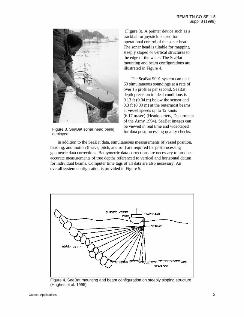
Figure 4. SeaBat mounting and beam configuration on steeply sloping structure(Hughes et al. 1995)
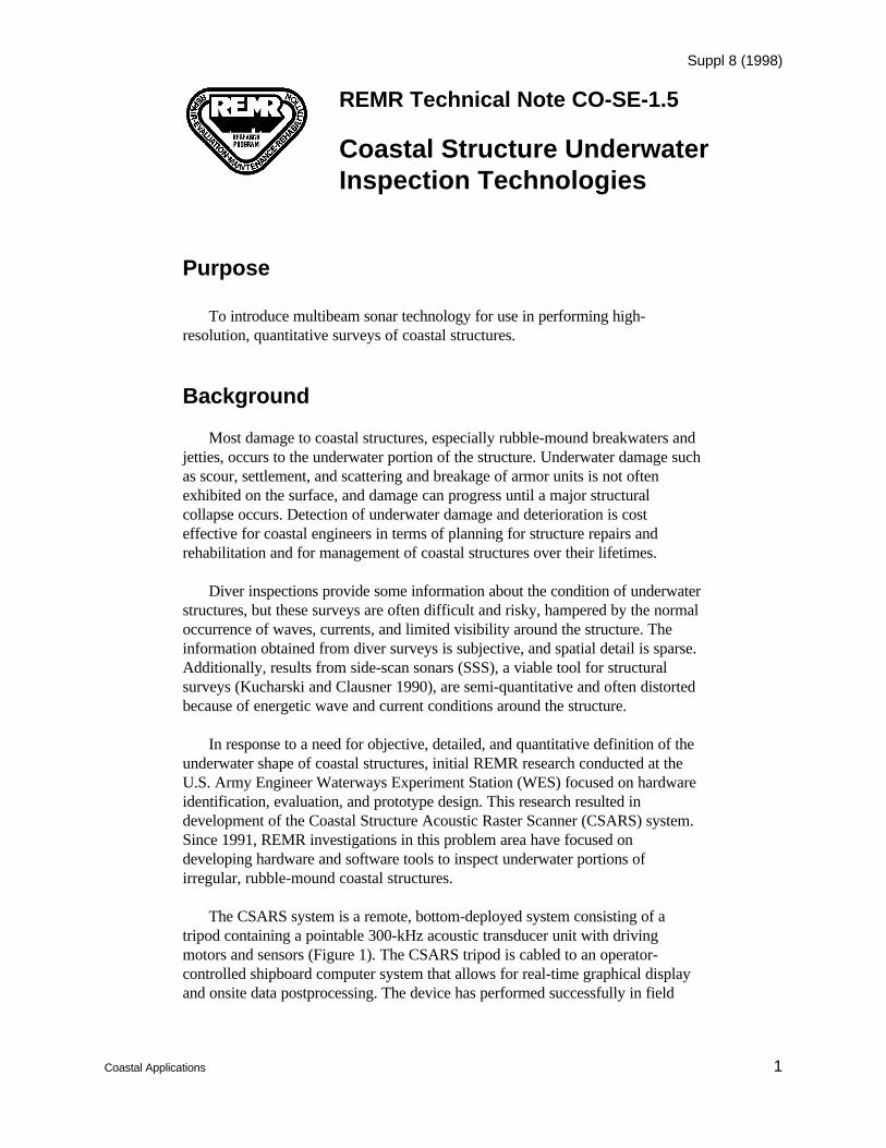
Figure 3. SeaBat sonar head being deployed
(Figure 3). A pointer device such as atrackball or joystick is used foroperational control of the sonar head.The sonar head is tiltable for mappingsteeply sloped or vertical structures tothe edge of the water. The SeaBatmounting and beam configurations areillustrated in Figure 4.
The SeaBat 9001 system can take60 simultaneous soundings at a rate ofover 15 profiles per second. SeaBatdepth precision in ideal conditions is0.13 ft (0.04 m) below the sensor and0.3 ft (0.09 m) at the outermost beamsat vessel speeds up to 12 knots(6.17 m/sec) (Headquarters, Departmentof the Army 1994). SeaBat images canbe viewed in real time and videotapedfor data postprocessing quality checks.
In addition to the SeaBat data, simultaneous measurements of vessel position,heading, and motion (heave, pitch, and roll) are required for postprocessinggeometric data corrections. Bathymetric data corrections are necessary to produceaccurate measurements of true depths referenced to vertical and horizontal datumfor individual beams. Computer time tags of all data are also necessary. Anoverall system configuration is provided in Figure 5.

REMR TN CO-SE-1.5Suppl 8 (1998)
4 Coastal Applications
Once geometrically corrected and processed, the SeaBat provides a dense dataset of xyz coordinates of point data (spot) elevations. From this data set, a three-dimensional mesh surface connecting the spot elevations (called digital elevationmodels or DEMs, and also called digital terrain models or DTMs), can be createdin addition to specified cross sections and contour maps. A DEM from theYaquina Bay North Jetty Survey (see Table 1) is provided as an example inFigure 6.
SeaBat Field Demonstrations and Trials
In 1993 and 1994, information about the potential uses of the SeaBat systemwas disseminated by the WES team throughout the hydrographic surveycommunity. As a result, several U.S. Army Corps of Engineers (USACE)Districts and hydrographic survey contractors sponsored SeaBat systemdemonstrations for varied applications. Table 1 lists those demonstrations attendedby WES personnel. Demonstration attendees included personnel from otherUSACE Districts, academia, and private hydrographic surveyors.
Development of the SeaBat system and its application to coastal structuresurveys continued to evolve as the system was demonstrated and tested. Equipment improvements included innovative mounts and data collectionhardware and software. Data collection procedures were tested, data densityrequirements were explored, and processing techniques were refined.
Summary
The demonstrations and success of the field trials have proved that thecommercially available SeaBat multibeam system can be applied for use in coastalstructure underwater surveys. Hydrographic surveying using state-of-the-artmultibeam swath systems provides nearly 100-percent bathymetric coverage of thestructure up to the edge of the water, resulting in a detailed and quantitativedefinition of the underwater shape of coastal structures. The SeaBat swathsystems and others like it are fast becoming standard equipment for shallow-watersurveying applications. Several USACE Districts have purchased multibeamsystems or are including multibeam sonars in specifications for private surveycontractors. Additional details of the SeaBat 9001 and description of othermultibeam swath systems employed on USACE hydrographic survey contracts areprovided in Engineer Manual 1110-2-1003, “Hydrographic Surveying”(Headquarters, Department of the Army 1994).

REMR TN CO-SE-1.5Suppl 8 (1998)
Coastal Applications 5
Figure 5. SeaBat system configuration (Headquarters, Department of the Army1994)

REMR TN CO-SE-1.5Suppl 8 (1998)
6 Coastal Applications
Figure 6. DEM of Yaquina Bay north jetty and Yaquina Reef below-waterbathymetry (Hughes et al. 1995)
Table 1SeaBat Demonstrations and Field Trials
Sponsor Location Application
Demonstrations
USACE District, Los Angeles Los Angeles, CA San Pedro Breakwater
USACE District, Memphis Memphis, TN Bridge pier scour on Mississippi River
Oceaneering, Solus Schall Division St. Louis, MO Missouri River Bridge pier scour (after(Upper Marlboro, MD) Flood of 1993)
EMC, Inc., (Greenwood, MS) Crescent City, CA Harbor entrance survey (dolosinspection)
Ocean Surveys, Inc. (Old Saybrook, Old Saybrook, CT Connecticut River entrance on LongCT) Island Sound
WES Duck, NC CHL Field Research Facility
Field Trials
USACE District, Buffalo, and WES Cleveland, OH Cuyahoga River retaining structurereconnaissance survey
USACE District, Los Angeles, and Los Angeles, CA Los Angeles (San Pedro) Harbor andWES Long Beach breakwaters
USACE District, New York Long Island, NY Shinnecock and Moriches Inlets
USACE District, Philadelphia, PA Rehoboth, DE Indian River Inlet
WES and USACE District, Portland Newport, OR Yaquina Bay north jetty survey
REMR TN CO-SE-1.5Suppl 8 (1998)
Coastal Applications 7
References
Headquarters, Department of the Army. (1994). “Hydrographic surveying,”Engineer Manual 1110-2-1003, U.S. Army Corps of Engineers, Washington,D.C.
Hughes, S.A., Prickett, T.L., Tubman, M.W., and Corson, W.D. (1995).“Monitoring of the Yaquina Bay entrance north jetty at Newport, Oregon;summary and result,” Technical Report CERC-95-9, U.S. Army EngineerWaterways Experiment Station, Vicksburg, MS.
Kucharski, W.M., and Clausner, J.E. (1990). “Underwater inspection of coastalstructures using commercially available sonars,” Technical Report REMR-CO-11, U.S. Army Engineer Waterways Experiment Station, Vicksburg, MS.
Lott, J.W. (1991). “Coastal Structure Acoustic Raster Scanner (CSARS) systemfor underwater inspection,” The REMR Bulletin 8 (3), U.S. Army EngineerWaterways Experiment Station, Vicksburg, MS.
Lott, J.W. Howell, G.L., and Higley, P.D. (1990). “Development of the CoastalStructure Acoustic Raster Scanner,” Proceedings, U.S. Army Corps ofEngineers Seventh Remote Sensing Symposium.