
Coast Guard, Dept. of Homeland Security Pt. 54€¦ · · 2018-03-17Coast Guard, Dept. of...
35
131 Coast Guard, Dept. of Homeland Security Pt. 54 hold a valid commission issued by the National Board of Boiler and Pressure Vessel Inspectors. After installation, heating boilers must be inspected for compliance with this part by a marine inspector. (b) Automatically controlled boilers must be subjected to the operating tests prescribed in part 63 of this sub- chapter. (c) All heating boilers must have the operation of their pressure relieving devices checked after the final installa- tion. [CGD 81–79, 50 FR 9436, Mar. 8, 1985, as amended by USCG–2003–16630, 73 FR 65164, Oct. 31, 2008] § 53.10–10 Certification by stamping. Stamping of heating boilers shall be as indicated in HG–530 of section IV of the ASME Boiler and Pressure Vessel Code (incorporated by reference; see 46 CFR 53.01–1). [USCG–2003–16630, 73 FR 65164, Oct. 31, 2008] § 53.10–15 Manufacturers’ data report forms. The manufacturers’ data report forms required by HG–520 of section IV of the ASME Boiler and Pressure Ves- sel Code (incorporated by reference; see 46 CFR 53.01–1) must be made available to the marine inspector for review. The Authorized Inspector’s National Board commission number must be included on the manufacturers’ data report forms. [USCG–2003–16630, 73 FR 65164, Oct. 31, 2008] Subpart 53.12—Instruments, Fittings, and Controls (Article 6) § 53.12–1 General (modifies HG–600 through HG–640). (a) The instruments, fittings and con- trols for heating boilers shall be as in- dicated in HG–600 through HG–640 of section IV of the ASME Boiler and Pressure Vessel Code (incorporated by reference; see 46 CFR 53.01–1) except as noted otherwise in this section. (b) For control systems for auto- matic auxiliary heating equipment, the requirements in part 63 of this sub- chapter govern and shall be followed. [CGFR 68–82, 33 FR 18826, Dec. 18, 1968, as amended by USCG–2003–16630, 73 FR 65164, Oct. 31, 2008] PART 54—PRESSURE VESSELS Subpart 54.01—General Requirements Sec. 54.01–1 Incorporation by reference 54.01–2 Adoption of division 1 of section VIII of the ASME Boiler and Pressure Vessel Code. 54.01–5 Scope (modifies U–1 and U–2). 54.01–10 Steam-generating pressure vessels (modifies U–1(g)). 54.01–15 Exemptions from shop inspection and plan approval (modifiesU–1(c)(2)). 54.01–17 Pressure vessel for human occu- pancy (PVHO). 54.01–18 Plan approval. 54.01–25 Miscellaneous pressure components (modifies UG–11). 54.01–30 Loadings (modifies UG–22). 54.01–35 Corrosion (modifies UG–25). 54.01–40 External pressure (modifies UG– 28). Subpart 54.03—Low Temperature Operation 54.03–1 Scope. 54.03–5 General. Subpart 54.05—Toughness Tests 54.05–1 Scope (replaces UG–84). 54.05–3 Tests required. 54.05–5 Toughness test specimens. 54.05–6 Toughness test temperatures. 54.05–10 Certification of material toughness tests. 54.05–15 Weldment toughness tests—proce- dure qualifications. 54.05–16 Production toughness testing. 54.05–17 Weld toughness test acceptance cri- teria. 54.05–20 Impact test properties for service of 0 °F. and below. 54.05–25 [Reserved] 54.05–30 Allowable stress values at low tem- peratures. Subpart 54.10—Inspection, Reports, and Stamping 54.10–1 Scope (modifies UG–90 through UG– 103 and UG–115 through UG–120). 54.10–3 Marine inspectors (replaces UG–90 and UG–91, and modifies UG–92 through UG–103). 54.10–5 Maximum allowable working pres- sure (reproduces UG–98). 54.10–10 Standard hydrostatic test (modifies UG–99). VerDate Mar<15>2010 09:56 Dec 08, 2010 Jkt 220192 PO 00000 Frm 00141 Fmt 8010 Sfmt 8010 Y:\SGML\220192.XXX 220192 jdjones on DSK8KYBLC1PROD with CFR
Transcript of Coast Guard, Dept. of Homeland Security Pt. 54€¦ · · 2018-03-17Coast Guard, Dept. of...

131
Coast Guard, Dept. of Homeland Security Pt. 54
hold a valid commission issued by the National Board of Boiler and Pressure Vessel Inspectors. After installation, heating boilers must be inspected for compliance with this part by a marine inspector.
(b) Automatically controlled boilers must be subjected to the operating tests prescribed in part 63 of this sub-chapter.
(c) All heating boilers must have the operation of their pressure relieving devices checked after the final installa-tion.
[CGD 81–79, 50 FR 9436, Mar. 8, 1985, as amended by USCG–2003–16630, 73 FR 65164, Oct. 31, 2008]
§ 53.10–10 Certification by stamping.
Stamping of heating boilers shall be as indicated in HG–530 of section IV of the ASME Boiler and Pressure Vessel Code (incorporated by reference; see 46 CFR 53.01–1).
[USCG–2003–16630, 73 FR 65164, Oct. 31, 2008]
§ 53.10–15 Manufacturers’ data report forms.
The manufacturers’ data report forms required by HG–520 of section IV of the ASME Boiler and Pressure Ves-sel Code (incorporated by reference; see 46 CFR 53.01–1) must be made available to the marine inspector for review. The Authorized Inspector’s National Board commission number must be included on the manufacturers’ data report forms.
[USCG–2003–16630, 73 FR 65164, Oct. 31, 2008]
Subpart 53.12—Instruments, Fittings, and Controls (Article 6)
§ 53.12–1 General (modifies HG–600 through HG–640).
(a) The instruments, fittings and con-trols for heating boilers shall be as in-dicated in HG–600 through HG–640 of section IV of the ASME Boiler and Pressure Vessel Code (incorporated by reference; see 46 CFR 53.01–1) except as noted otherwise in this section.
(b) For control systems for auto-matic auxiliary heating equipment, the
requirements in part 63 of this sub-chapter govern and shall be followed.
[CGFR 68–82, 33 FR 18826, Dec. 18, 1968, as amended by USCG–2003–16630, 73 FR 65164, Oct. 31, 2008]
PART 54—PRESSURE VESSELS
Subpart 54.01—General Requirements
Sec. 54.01–1 Incorporation by reference 54.01–2 Adoption of division 1 of section VIII
of the ASME Boiler and Pressure Vessel Code.
54.01–5 Scope (modifies U–1 and U–2). 54.01–10 Steam-generating pressure vessels
(modifies U–1(g)). 54.01–15 Exemptions from shop inspection
and plan approval (modifiesU–1(c)(2)). 54.01–17 Pressure vessel for human occu-
pancy (PVHO). 54.01–18 Plan approval. 54.01–25 Miscellaneous pressure components
(modifies UG–11). 54.01–30 Loadings (modifies UG–22). 54.01–35 Corrosion (modifies UG–25). 54.01–40 External pressure (modifies UG– 28).
Subpart 54.03—Low Temperature Operation
54.03–1 Scope. 54.03–5 General.
Subpart 54.05—Toughness Tests
54.05–1 Scope (replaces UG–84). 54.05–3 Tests required. 54.05–5 Toughness test specimens. 54.05–6 Toughness test temperatures. 54.05–10 Certification of material toughness
tests. 54.05–15 Weldment toughness tests—proce-
dure qualifications. 54.05–16 Production toughness testing. 54.05–17 Weld toughness test acceptance cri-
teria. 54.05–20 Impact test properties for service of
0 °F. and below. 54.05–25 [Reserved] 54.05–30 Allowable stress values at low tem-
peratures.
Subpart 54.10—Inspection, Reports, and Stamping
54.10–1 Scope (modifies UG–90 through UG– 103 and UG–115 through UG–120).
54.10–3 Marine inspectors (replaces UG–90 and UG–91, and modifies UG–92 through UG–103).
54.10–5 Maximum allowable working pres-sure (reproduces UG–98).
54.10–10 Standard hydrostatic test (modifies UG–99).
VerDate Mar<15>2010 09:56 Dec 08, 2010 Jkt 220192 PO 00000 Frm 00141 Fmt 8010 Sfmt 8010 Y:\SGML\220192.XXX 220192jdjo
nes
on D
SK
8KY
BLC
1PR
OD
with
CF
R

132
46 CFR Ch. I (10–1–10 Edition) § 54.01–1
54.10–15 Pneumatic test (modifies UG–100). 54.10–20 Marking and stamping. 54.10–25 Manufacturers’ data report forms
(modifies UG–120).
Subpart 54.15—Pressure-Relief Devices
54.15–1 General (modifies UG–125 through UG–137).
54.15–3 Definitions (modifies Appendix 3). 54.15–5 Protective devices (modifies UG–
125). 54.15–10 Safety and relief valves (modifies
UG–126). 54.15–13 Rupture disks (modifies UG–127). 54.15–15 Relief devices for unfired steam
boilers, evaporators, and heat exchangers (modifies UG–126).
54.15–25 Minimum relief capacities for cargo tanks containing compressed or liquefied gas.
Subpart 54.20—Fabrication by Welding
54.20–1 Scope (modifies UW–1 through UW– 65).
54.20–2 Fabrication for hazardous materials (replaces UW–2(a)).
54.20–3 Design (modifies UW–9, UW–11(a), UW–13, and UW–16).
54.20–5 Welding qualification tests and pro-duction testing (modifies UW–26, UW–28, UW–29, UW–47, and UW–48).
Subpart 54.23—Fabrication by Brazing
54.23–1 Scope (modifies UB–1).
Subpart 54.25—Construction With Carbon, Alloy, and Heat Treated Steels
54.25–1 Scope. 54.25–3 Steel plates (modifies UCS–6). 54.25–5 Corrosion allowance (replaces UCS–
25). 54.25–7 Requirements for postweld heat
treatment (modifies UCS–56). 54.25–8 Radiography (modifies UW–11(a),
UCS–57, UNF–57, UHA–33, and UHT–57). 54.25–10 Low temperature operation—fer-
ritic steels (replaces UCS–65 through UCS–67).
54.25–15 Low temperature operation—high alloy steels (modifies UHA–23(b) and UHA–51).
54.25–20 Low temperature operation—fer-ritic steels with properties enhanced by heat treatment (modifies UHT–5(c), UHT–6, UHT–23, and UHT–82).
54.25–25 Welding of quenched and tempered steels (modifies UHT–82).
Subpart 54.30—Mechanical Stress Relief
54.30–1 Scope. 54.30–3 Introduction. 54.30–5 Limitations and requirements.
54.30–10 Method of performing mechanical stress relief.
54.30–15 Requirement for analysis and com-putation.
AUTHORITY: 33 U.S.C. 1509; 43 U.S.C. 1333; 46 U.S.C. 3306, 3703; E.O. 12234, 45 FR 58801, 3 CFR, 1980 Comp., p. 277; Department of Homeland Security Delegation No. 0170.1.
SOURCE: CGFR 68–82, 33 FR 18828, Dec. 18, 1968, unless otherwise noted.
Subpart 54.01—General Requirements
§ 54.01–1 Incorporation by reference. (a) Certain material is incorporated
by reference into this part with the ap-proval of the Director of the Federal Register under 5 U.S.C. 552(a) and 1 CFR part 51. To enforce any edition other than that specified in this sec-tion, the Coast Guard must publish no-tice of change in the FEDERAL REG-ISTER and the material must be avail-able to the public. All approved mate-rial is available for inspection at the National Archives and Records Admin-istration (NARA). For information on the availability of this material at NARA, call 202–741–6030 or go to http:// www.archives.gov/federallregister/ codeloflfederallregulations/ ibrllocations.html. The material is also available for inspection at the U.S. Coast Guard, Office of Design and Engi-neering Standards (CG–521), 2100 2nd St. SW., Stop 7126, Washington, DC 20593– 7126, and is available from the sources listed below.
(b) American Society of Mechanical En-gineers (ASME) International, Three Park Avenue, New York, NY 10016–5990:
(1) ASME Boiler and Pressure Vessel Code, Section VIII, Division 1, Rules for Construction of Pressure Vessels (1998 with 1999 and 2000 addenda) (‘‘Section VIII of the ASME Boiler and Pressure Vessel Code’’), 54.01–2; 54.01–5; 54.01–15; 54.01–18; 54.01–25; 54.01–30; 54.01– 35; 54.03–1; 54.05–1; 54.10–1; 54.10–3; 54.10– 5; 54.10–10; 54.10–15; 54.15–1; 54.15–5; 54.15– 10; 54.15–13; 54.20–1; 54.20–3; 54.25–1; 54.25– 3; 54.25–8; 54.25–10; 54.25–15; 54.25–20; 54.30–3; 54.30–5; 54.30–10; and
(2) [Reserved] (c) ASTM International (formerly Amer-
ican Society for Testing and Materials) (ASTM), 100 Barr Harbor Drive, West Conshohocken, PA 19428–2959:
VerDate Mar<15>2010 09:56 Dec 08, 2010 Jkt 220192 PO 00000 Frm 00142 Fmt 8010 Sfmt 8010 Y:\SGML\220192.XXX 220192jdjo
nes
on D
SK
8KY
BLC
1PR
OD
with
CF
R

133
Coast Guard, Dept. of Homeland Security § 54.01–2
(1) ASTM A 20/A 20M–97a, Standard Specification for General Require-ments for Steel Plates for Pressure Vessels (‘‘ASTM A 20’’), 54.05–10; 54.25– 10;
(2) ASTM A 203/A 203M–97, Standard Specification for Pressure Vessel Plates, Alloy Steel, Nickel (‘‘ASTM A 203’’), 54.05–20;
(3) ASTM A 370–97a, Standard Test Methods and Definitions for Mechan-ical Testing of Steel Products (‘‘ASTM A 370’’), 54.25–20;
(4) ASTM E 23–96, Standard Test Methods for Notched Bar Impact Test-ing of Metallic Materials (‘‘ASTM Specification E 23’’), 54.05–5; and
(5) ASTM E 208–95a, Standard Test Method for Conducting Drop-Weight Test to Determine Nil-Ductility Tran-sition Temperature of Ferritic Steels (‘‘ASTM Specification E 208’’), 54.05–5.
(d) Compressed Gas Association (CGA), 500 Fifth Avenue, New York, NY 10036:
(1) S–1.2, Pressure Relief Device Standards—Part 2—Cargo and Portable Tanks for Compressed Gases, 1979 (‘‘CGA S–1.2’’), 54.15–10; and
(2) [Reserved] (e) Manufacturers Standardization So-
ciety of the Valve and Fittings Industry,
Inc. (MSS), 127 Park Street NE, Vienna, VA 22180:
(1) SP–25–1998 Standard Marking Sys-tem for Valves, Fittings, Flanges and Unions (1998) (‘‘MSS SP–25’’), 54.01–25; and
(2) [Reserved]
[USCG–2003–16630, 73 FR 65164, Oct. 31, 2008, as amended by USCG–2009–0702, 74 FR 49228, Sept. 25, 2009]
§ 54.01–2 Adoption of division 1 of sec-tion VIII of the ASME Boiler and Pressure Vessel Code.
(a) Pressure vessels shall be designed, constructed, and inspected in accord-ance with section VIII of the ASME Boiler and Pressure Vessel Code (incor-porated by reference, see 46 CFR 54.01– 1), as limited, modified, or replaced by specific requirements in this part. The provisions in the appendices to section VIII of the ASME Boiler and Pressure Vessel Code are adopted and shall be followed when the requirements in sec-tion VIII make them mandatory. For general information, Table 54.01–2(a) lists the various paragraphs in section VIII of the ASME Boiler and Pressure Vessel Code that are limited, modified, or replaced by regulations in this part.
TABLE 54.01–2(a)—LIMITATIONS AND MODIFICATIONS IN THE ADOPTION OF SECTION VIII OF THE ASME BOILER AND PRESSURE VESSEL CODE
Paragraphs in section VIII of the ASME Boiler and Pressure Vessel Code1 and dis-position Unit of this part
U–1 and U–2 modified by .............................................................................................. 54.01–5 through 54.01–15. U–1(c) replaced by ......................................................................................................... 54.01–5. U–1(d) replaced by ......................................................................................................... 54.01–5(a) and 54.01–15. U–1(g) modified by ......................................................................................................... 54.01–10. U–1(c)(2) modified by ..................................................................................................... 54.01–15. UG–11 modified by ........................................................................................................ 54.01–25. UG–22 modified by ........................................................................................................ 54.01–30. UG–25 modified by ........................................................................................................ 54.01–35. UG–28 modified by ........................................................................................................ 54.01–40. UG–84 replaced by ........................................................................................................ 54.05–1. UG–90 and UG–91 replaced by .................................................................................... 54.10–3. UG–92 through UG–103 modified by ............................................................................ 54.10–1 through 54.10–15. UG–98 reproduced by .................................................................................................... 54.10–5. UG–115 through UG–120 modified by .......................................................................... 54.10–1. UG–116, except (k), replaced by ................................................................................... 54.10–20(a). UG–116(k) replaced by .................................................................................................. 54.10–20(b). UG–117 replaced by ...................................................................................................... 54.10–20(c). UG–118 replaced by ...................................................................................................... 54.10–20(a). UG–119 modified by ...................................................................................................... 54.10–20(d). UG–120 modified by ...................................................................................................... 54.10–25. UG–125 through UG–137 modified by .......................................................................... 54.15–1 through 54.15–15. UW–1 through UW–65 modified by ............................................................................... 54.20–1. UW–2(a) replaced by ..................................................................................................... 54.01–5(b) and 54.20–2. UW–2(b) replaced by ..................................................................................................... 54.01–5(b) and 54.20–2. UW–9, UW–11(a), UW–13, and UW–16 modified by .................................................... 54.20–3. UW–11(a) modified by ................................................................................................... 54.25–8. UW–26, UW–27, UW–28, UW–29, UW–47, and UW–48 modified by .......................... 54.20–5. UB–1 modified by ........................................................................................................... 54.23–1 UB–2 modified by ........................................................................................................... 52.01–95(d) and 56.30–30(b)(1).
VerDate Mar<15>2010 09:56 Dec 08, 2010 Jkt 220192 PO 00000 Frm 00143 Fmt 8010 Sfmt 8010 Y:\SGML\220192.XXX 220192jdjo
nes
on D
SK
8KY
BLC
1PR
OD
with
CF
R

134
46 CFR Ch. I (10–1–10 Edition) § 54.01–5
TABLE 54.01–2(a)—LIMITATIONS AND MODIFICATIONS IN THE ADOPTION OF SECTION VIII OF THE ASME BOILER AND PRESSURE VESSEL CODE—Continued
Paragraphs in section VIII of the ASME Boiler and Pressure Vessel Code1 and dis-position Unit of this part
UCS–6 modified by ........................................................................................................ 54.25–3. UCS–56 modified by ...................................................................................................... 54.25–7. UCS–57, UNF–57, UHA–33, and UHT–57 modified by ................................................ 54.25–8. UCS–65 through UCS–67 replaced by .......................................................................... 54.25–10. UHA–23(b) and UHA–51 modified by ............................................................................ 54.25–15. UHT–5(c), UHT–6, and UHT–23 modified by ................................................................ 54.25–20. UHT–82 modified by ...................................................................................................... 54.25–20 and 54.25–25. Appendix 3 modified by .................................................................................................. 54.15–3.
1 The references to specific provisions in section VIII of the ASME Boiler and Pressure Vessel Code are coded. The first letter, such as ‘‘U,’’ refers to division 1 of section VIII. The second letter, such as ‘‘G,’’ refers to a subsection within section VIII. The number refers to the paragraph within the subsection.
(b) References to the ASME Boiler and Pressure Vessel Code, such as para-graph UG–125, indicate:
U = Division 1 of section VIII of the ASME Boiler and Pressure Vessel Code.
G = Part containing general require-ments.
125 = Paragraph within part. (c) When a paragraph or a section of
the regulations in this part relates to material in section VIII of the ASME Boiler and Pressure Vessel Code, the relationship with the code will be shown immediately following the head-ing of the section or at the beginning of the paragraph, as follows:
(1) (Modifies Ulll.) This indicates that the material in Ulll is gen-erally applicable but is being altered, amplified or augmented.
(2) (Replaces Ulll.) This indicates that Ulll does not apply.
(3) (Reproduces Ulll.) This indi-cates that Ulll is being identically reproduced for convenience, not for emphasis.
[CGFR 68–82, 33 FR 18828, Dec. 18, 1968, as amended by CGFR 69–127, 35 FR 9976, June 17, 1970; CGFR 72–59R, 37 FR 6188, Mar. 25, 1972; CGD 72–206R, 38 FR 17226, June 29, 1973; CGD 73–254, 40 FR 40163, Sept. 2, 1975; CGD 77–147, 47 FR 21809, May 20, 1982; CGD 85–061, 54 FR 50963, Dec. 11, 1989. Redesignated by CGD 88– 032, 56 FR 35822, July 29, 1991; USCG–2003– 16630, 73 FR 65164, Oct. 31, 2008]
§ 54.01–5 Scope (modifies U–1 and U–2).
(a) This part contains requirements for pressure vessels. Table 54.01–5(a) gives a breakdown by parts in this sub-chapter of the regulations governing various types of pressure vessels, boil-ers, and thermal units.
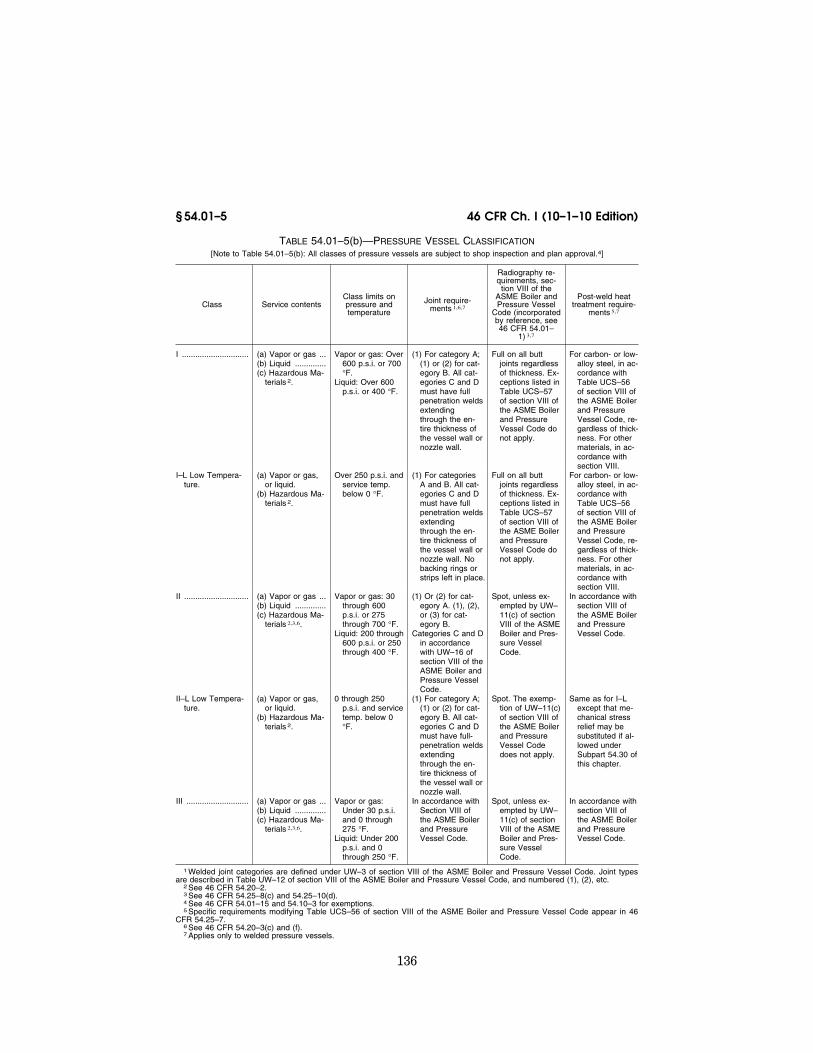
(b) Pressure vessels are divided into Classes I, I-L (low temperature), II, II- L (low temperature), and III. Table 54.01–5(b) describes these classes and sets out additional requirements for welded pressure vessels.
(c) The requirements for pressure vessels by class are as follows:
(1) Class I-L and II-L pressure vessels must meet the applicable requirements in this part.
(2) Pressure vessels containing haz-ardous materials as defined in § 150.115 of this chapter must meet the require-ments of this part or, as applicable, the requirements in 49 CFR parts 171–177 or part 64 of this chapter.
(3) Except as provided in paragraph (c)(4) of this section, Classes I, II, and III pressure vessels not containing haz-ardous materials must be designed and constructed in accordance with the re-quirements in Section VIII, division 1, of the ASME Boiler and Pressure Ves-sel Code (incorporated by reference; see 46 CFR 54.01–1) and must be stamped with the ASME ‘‘U’’ symbol. These pressure vessels must also comply with the requirements that are listed or pre-scribed in paragraphs (d) through (g) of this section. Compliance with other provisions in this part is not required.
(4) Classes II and III pressure vessels that have a net internal volume of less than 0.14 cubic meters (5 cubic feet) and do not contain hazardous materials must be stamped with either the ASME ‘‘U’’ or ‘‘UM’’ symbol. Compliance with other provisions in this part is not re-quired.
(d) Pressure vessels described in para-graph (c)(3) of this section must—
VerDate Mar<15>2010 09:56 Dec 08, 2010 Jkt 220192 PO 00000 Frm 00144 Fmt 8010 Sfmt 8010 Y:\SGML\220192.XXX 220192jdjo
nes
on D
SK
8KY
BLC
1PR
OD
with
CF
R

135
Coast Guard, Dept. of Homeland Security § 54.01–5
(1) Have detailed plans that include the information required by § 54.01–18 (approved by the Office of Management and Budget under OMB control number 2130–0181);
(2) Meet § 54.01–35, § 54.20–3(c), and § 54.25–3 of this part;
(3) Have pressure relief devices re-quired by subpart 54.15;
(4) Meet the applicable requirements in §§ 54.10–3, 54.10–20, and 54.10–25 for in-spection, reports, and stamping;
(5) If welded, meet the post weld heat treatment and minimum joint and ra-diography requirement in Table 54.01– 5(b); and
(6) If a steam generating pressure vessel, meet § 54.01–10.
(e) The plans required by paragraph (d)(1) of this section must be certified by a registered professional engineer to meet the design requirements in para-graph (d) of this section and in section VIII, division 1, of the ASME Boiler and Pressure Vessel Code. The certifi-cation must appear on all drawings and analyses. The plans must be made available to the Coast Guard prior to the inspection required by § 54.10–3(c).
(f) If a pressure vessel has more than one independent chamber and the chambers have different classifica-tions, each chamber must, as a min-imum, meet the requirements for its classification. If a single classification for the entire pressure vessel is pre-ferred, the classification selected must be one that is required to meet all of the regulations applicable to the clas-sification that is not selected. For ex-ample, if one chamber is Class I and one chamber is Class II-L, the only sin-gle classification that can be selected is Class I-L.
(g) The design pressure for each interface between two chambers in a multichambered pressure vessel must be—
(1) The maximum allowable working pressure (gauge) in the chamber with the higher pressure; or
(2) If one chamber is a vacuum cham-ber, the maximum allowable working pressure (absolute) in the other cham-ber minus the least operating pressure (absolute) in the vacuum chamber.
TABLE 54.01–5(a)—REGULATION REFERENCE FOR BOILERS, PRESSURE VESSELS, AND THERMAL UNITS
Service and pressure tempera-ture boundaries
Part of sub-chapter reg-ulating me-chanical de-
sign
Part of sub-chapter reg-ulating auto-matic con-
trol
Main (power) boiler: All ............. 52 62 Pressure vessel: All ................... 54 NA Fired auxiliary boiler 1 (combus-
tion products or electricity): (a) Steam:
More than 103 kPa (15 psig) ......................... 52 2 62 or 63
Equal to or less than 103 kPa (15 psig) .... 53 63
(b) Hot water heating: More than 689 kPa
(100 psig) or 121 °C (250 °F) ................... 52 63
Equal to or less than 689 kPa (100 psig) and 121 °C (250 °F) 53 63
(c) Hot water supply: More than 689 kPa
(100 psig) or 121 °C (250 °F) ................... 52 63
Equal to or less than 689 kPa (100 psig) and 121 °C (250 °F) 53 63
Other: (a) Fired thermal fluid heat-
ers: All ............................. 52 63 (b) Unfired steam boiler:
More than 206 kPa (30 psig) or 454 °C (850 °F) 3 .......................... 52 NA
Equal to or less than 206 kPa (30 psig) and 454 °C (850 °F) 54 NA
(c) Evaporators and heat exchangers: More than 103 kPa (15 psig) 4 ......... 54 NA
(d) Unfired hot water supply or heating boiler: More than 103 kPa (15 psig) 4 54 NA
1 Including exhaust gas types. 2 Boilers with heat input ratings >=12,500,000 Btu/hr. must
have controls that meet part 62. Boilers with heat input ratings <12,500,000 Btu/hr. must have controls that meet part 63.
3 Temperature of working fluid. 4 Relief device is required even if designed for less than
103 kPa (15 psig).
VerDate Mar<15>2010 09:56 Dec 08, 2010 Jkt 220192 PO 00000 Frm 00145 Fmt 8010 Sfmt 8010 Y:\SGML\220192.XXX 220192jdjo
nes
on D
SK
8KY
BLC
1PR
OD
with
CF
R
136
46 CFR Ch. I (10–1–10 Edition) § 54.01–5
TABLE 54.01–5(b)—PRESSURE VESSEL CLASSIFICATION [Note to Table 54.01–5(b): All classes of pressure vessels are subject to shop inspection and plan approval.4]
Class Service contents Class limits on pressure and temperature
Joint require-ments 1,6,7
Radiography re-quirements, sec-
tion VIII of the ASME Boiler and Pressure Vessel
Code (incorporated by reference, see 46 CFR 54.01–
1) 3,7
Post-weld heat treatment require-
ments 5,7
I .............................. (a) Vapor or gas ...(b) Liquid ..............(c) Hazardous Ma-
terials 2.
Vapor or gas: Over 600 p.s.i. or 700 °F.
Liquid: Over 600 p.s.i. or 400 °F.
(1) For category A; (1) or (2) for cat-egory B. All cat-egories C and D must have full penetration welds extending through the en-tire thickness of the vessel wall or nozzle wall.
Full on all butt joints regardless of thickness. Ex-ceptions listed in Table UCS–57 of section VIII of the ASME Boiler and Pressure Vessel Code do not apply.
For carbon- or low- alloy steel, in ac-cordance with Table UCS–56 of section VIII of the ASME Boiler and Pressure Vessel Code, re-gardless of thick-ness. For other materials, in ac-cordance with section VIII.
I–L Low Tempera-ture.
(a) Vapor or gas, or liquid.
(b) Hazardous Ma-terials 2.
Over 250 p.s.i. and service temp. below 0 °F.
(1) For categories A and B. All cat-egories C and D must have full penetration welds extending through the en-tire thickness of the vessel wall or nozzle wall. No backing rings or strips left in place.
Full on all butt joints regardless of thickness. Ex-ceptions listed in Table UCS–57 of section VIII of the ASME Boiler and Pressure Vessel Code do not apply.
For carbon- or low- alloy steel, in ac-cordance with Table UCS–56 of section VIII of the ASME Boiler and Pressure Vessel Code, re-gardless of thick-ness. For other materials, in ac-cordance with section VIII.
II ............................. (a) Vapor or gas ...(b) Liquid ..............(c) Hazardous Ma-
terials 2,3,6.
Vapor or gas: 30 through 600 p.s.i. or 275 through 700 °F.
Liquid: 200 through 600 p.s.i. or 250 through 400 °F.
(1) Or (2) for cat-egory A. (1), (2), or (3) for cat-egory B.
Categories C and D in accordance with UW–16 of section VIII of the ASME Boiler and Pressure Vessel Code.
Spot, unless ex-empted by UW– 11(c) of section VIII of the ASME Boiler and Pres-sure Vessel Code.
In accordance with section VIII of the ASME Boiler and Pressure Vessel Code.
II–L Low Tempera-ture.
(a) Vapor or gas, or liquid.
(b) Hazardous Ma-terials 2.
0 through 250 p.s.i. and service temp. below 0 °F.
(1) For category A; (1) or (2) for cat-egory B. All cat-egories C and D must have full- penetration welds extending through the en-tire thickness of the vessel wall or nozzle wall.
Spot. The exemp-tion of UW–11(c) of section VIII of the ASME Boiler and Pressure Vessel Code does not apply.
Same as for I–L except that me-chanical stress relief may be substituted if al-lowed under Subpart 54.30 of this chapter.
III ............................ (a) Vapor or gas ...(b) Liquid ..............(c) Hazardous Ma-
terials 2,3,6.
Vapor or gas: Under 30 p.s.i. and 0 through 275 °F.
Liquid: Under 200 p.s.i. and 0 through 250 °F.
In accordance with Section VIII of the ASME Boiler and Pressure Vessel Code.
Spot, unless ex-empted by UW– 11(c) of section VIII of the ASME Boiler and Pres-sure Vessel Code.
In accordance with section VIII of the ASME Boiler and Pressure Vessel Code.
1 Welded joint categories are defined under UW–3 of section VIII of the ASME Boiler and Pressure Vessel Code. Joint types are described in Table UW–12 of section VIII of the ASME Boiler and Pressure Vessel Code, and numbered (1), (2), etc.
2 See 46 CFR 54.20–2. 3 See 46 CFR 54.25–8(c) and 54.25–10(d). 4 See 46 CFR 54.01–15 and 54.10–3 for exemptions. 5 Specific requirements modifying Table UCS–56 of section VIII of the ASME Boiler and Pressure Vessel Code appear in 46
CFR 54.25–7. 6 See 46 CFR 54.20–3(c) and (f). 7 Applies only to welded pressure vessels.
VerDate Mar<15>2010 09:56 Dec 08, 2010 Jkt 220192 PO 00000 Frm 00146 Fmt 8010 Sfmt 8010 Y:\SGML\220192.XXX 220192jdjo
nes
on D
SK
8KY
BLC
1PR
OD
with
CF
R

137
Coast Guard, Dept. of Homeland Security § 54.01–15
(Approved by the Office of Management and Budget under OMB control number 2130–0181)
[CGFR 68–82, 33 FR 18828, Dec. 18, 1968, as amended by CGFR 69–127, 35 FR 9976, June 17, 1970; CGD 77–147, 47 FR 21809, May 20, 1982; 55 FR 696, Jan. 8, 1990; CGD 88–057, 55 FR 24236, June 15, 1990; CGD 85–061, 55 FR 41917, Oct. 16, 1990; CGD 95–027, 61 FR 26000, May 23, 1996; USCG– 2000–7790, 65 FR 58460, Sept. 29, 2000; USCG–2003–16630, 73 FR 65165, Oct. 31, 2008]
§ 54.01–10 Steam-generating pressure vessels (modifies U–1(g)).
(a) Pressure vessels in which steam is generated are classed as ‘‘Unfired Steam Boilers’’ except as required oth-erwise by paragraph (b) of this section. Unfired steam boilers must be fitted with an efficient water level indicator, a pressure gage, a blowdown valve, and an approved safety valve as required by § 54.15–15. Unfired steam boilers must be constructed in accordance with this part other than when the pressures are more than 206 kPa (30 psig) or the tem-peratures of the working fluid are more than 454 °C (850 °F) when such boilers must be constructed in accordance with part 52 of this subchapter.
(b) Vessels known as ‘‘Evaporators’’ or ‘‘Heat Exchangers’’ are not classi-fied as unfired steam boilers. They shall be fitted with an approved safety device as required under § 54.15–15 and constructed in accordance with this part.
(c) An evaporator in which steam is generated shall be fitted with an effi-cient water level indicator, a pressure gage, and a blowdown valve.
[CGFR 68–82, 33 FR 18828, Dec. 18, 1968, as amended by CGD 81–79, 50 FR 9436, Mar. 8, 1985; CGD 95–012, 60 FR 48044, Sept. 18, 1995; USCG–2003–16630, 73 FR 65166, Oct. 31, 2008]
§ 54.01–15 Exemptions from shop in-spection and plan approval (modifiesU–1(c)(2)).
(a) The following classifications are exempt from shop inspection and plan approval requirements of this part:
(1) Vessels containing water at a pressure not greater than 689 kPa (100 pounds per square inch gauge or ‘‘psig’’), and at a temperature not above 93 °C (200 °F) including those con-taining air, the compression of which serves only as a cushion. Air-charging lines may be permanently attached if the air pressure does not exceed 103 kPa (15 psig).
(2) Hot water supply storage tanks heated by steam or any other indirect
means when none of the following limi-tations is exceeded:
(i) A heat input of 58 kW (200,000 B.t.u. per hour);
(ii) A water temperature of 93 °C (200 °F);
(iii) A nominal water-containing ca-pacity of 454 liters (120 gallons); or
(iv) A pressure of 689 kPa (100 psig).
The exemption of any tank under this subparagraph requires that it shall be fitted with a safety relief valve of at least 1-inch diameter, set to relieve below the maximum allowable working pressure of the tank.
(3)(i) Vessels having an internal oper-ating pressure not exceeding 103 kPa (15 psig) with no limitation on size. (See UG–28(f) of section VIII of the ASME Boiler and Pressure Vessel Code (incorporated by reference; see 46 CFR 54.01–1.)
(ii) Cargo tanks of pressure vessel configuration are not included in the exemption in paragraph (a)(3)(i) of this section.
(4) Class I, II, and III pressure vessels that meet the requirements of § 54.01– 5(c)(3) and (c)(4).
(5) Condensers and heat exchangers, regardless of size, when the design is such that the liquid phase is not great-er than 689 kPa (100 psig) and 200 °F (93 °C) and the vapor phase is not greater than 103 kPa (15 psig) provided that the Officer in Charge, Marine Inspection is satisfied that system overpressure con-ditions are addressed by the owner or operator.
(b) For fluid conditioner fittings see § 56.15–1 of this subchapter.
[CGFR 68–82, 33 FR 18828, Dec. 18, 1968, as amended by CGFR 69–127, 35 FR 9977, June 17, 1970; CGFR 70–143, 35 FR 19906, Dec. 30, 1970; CGD 77–147, 47 FR 21810, May 20, 1982; USCG– 2003–16630, 73 FR 65166, Oct. 31, 2008; USCG– 2010–0759, 75 FR 60002, Sept. 29, 2010]
VerDate Mar<15>2010 09:56 Dec 08, 2010 Jkt 220192 PO 00000 Frm 00147 Fmt 8010 Sfmt 8010 Y:\SGML\220192.XXX 220192jdjo
nes
on D
SK
8KY
BLC
1PR
OD
with
CF
R

138
46 CFR Ch. I (10–1–10 Edition) § 54.01–17
§ 54.01–17 Pressure vessel for human occupancy (PVHO).
Pressure vessels for human occu-pancy (PVHO’s) must meet the require-ments of subpart B (Commercial Div-ing Operations) of part 197 of this chap-ter.
[CGD 76–009, 43 FR 53683, Nov. 16, 1978]
§ 54.01–18 Plan approval. (a) Manufacturers intending to fab-
ricate pressure vessels, heat exchang-ers, evaporators, and similar appur-tenances, covered by the regulations in this part shall submit detailed plans in accordance with subpart 50.20 of this subchapter.
(b) The following information shall be submitted:
(1) Calculations for all pressure con-tainment components including the maximum allowable working pressure, the hydrostatic or pneumatic test pres-sure, and the intended safety device setting.
(2) Joint design and methods of at-tachment of all pressure containment components.
(3) Foundations and supports (design and attachment).
(4) Pertinent calculations for pres-sure vessel foundations and/or sup-ports.
(5) A bill of material meeting the re-quirements of section VIII of section VIII of the ASME Boiler and Pressure Vessel Code (incorporated by reference; see 46 CFR 54.01–1), as modified by this part.
(6) A diagrammatic arrangement drawing of the assembled unit indi-cating location of internal and external components.
[CGFR 68–82, 33 FR 18828, Dec. 18, 1968, as amended by USCG–2003–16630, 73 FR 65166, Oct. 31, 2008]
§ 54.01–25 Miscellaneous pressure com-ponents (modifies UG–11).
(a) Pressure components for pressure vessels shall be as required by UG–11 of section VIII of the ASME Boiler and Pressure Vessel Code (incorporated by reference; see 46 CFR 54.01–1) except as noted otherwise in this section.
(b) All pressure components con-forming to an accepted ANSI (Amer-ican National Standards Institute)
Standard referred to in an adopted code, specification or standard or in this subchapter shall also be marked in accordance with MSS SP–25 (incor-porated by reference; see 46 CFR 54.01– 1).
[CGFR 68–82, 33 FR 18828, Dec. 18, 1968, as amended by CGFR 69–127, 35 FR 9977, June 17, 1970; USCG–2003–16630, 73 FR 65167, Oct. 31, 2008]
§ 54.01–30 Loadings (modifies UG–22). (a) The loadings for pressure vessels
shall be as required by UG–22 of section VIII of the ASME Boiler and Pressure Vessel Code (incorporated by reference; see 46 CFR 54.01–1) except as noted oth-erwise in this section.
(b) In evaluating loadings for certain pressure vessel applications, the Com-mandant may require consideration of the following loads in addition to those listed in UG–22 of section VIII of the ASME Boiler and Pressure Vessel Code:
(1) Loading imposed by vessel’s atti-tude in roll, list, pitch and trim.
(2) Dynamic forces due to ship mo-tions.
[CGFR 68–82, 33 FR 18828, Dec. 18, 1968, as amended by USCG–2003–16630, 73 FR 65167, Oct. 31, 2008]
§ 54.01–35 Corrosion (modifies UG– 25). (a) Vessels or portions of vessels sub-
ject to corrosion shall be as required by UG–25 of section VIII of the ASME Boiler and Pressure Vessel Code (incor-porated by reference; see 46 CFR 54.01– 1) except as noted otherwise in this sec-tion.
(b) The pressure portions of pressure vessels shall:
(1) Normally have a corrosion allow-ance of one-sixth of the calculated thickness, or one-sixteenth inch, whichever is smaller, added to the cal-culated thickness as determined by the applicable design formula.
(2) Be specifically evaluated in cases where unusually corrosive cargoes will be involved, for the possible increase of this corrosion allowance.
(3) Have no additional thickness re-quired when acceptable corrosion re-sistant materials are used.
(4) Not normally need additional thickness allowance when the effective stress (either S or SE depending on the design formula used) is 80 percent or
VerDate Mar<15>2010 09:56 Dec 08, 2010 Jkt 220192 PO 00000 Frm 00148 Fmt 8010 Sfmt 8010 Y:\SGML\220192.XXX 220192jdjo
nes
on D
SK
8KY
BLC
1PR
OD
with
CF
R

139
Coast Guard, Dept. of Homeland Security § 54.05–3
less of the allowable stress listed in section VIII of the ASME Boiler and Pressure Vessel Code for calculating thickness.
(c) Telltale holes shall not be per-mitted in pressure vessels containing dangerous fluids, such as acid, poison, corrosives, etc.
(d) Exemption from these corrosion allowance requirements will be granted by the Commandant in those cases where:
(1) The contents of the pressure ves-sel is judged to be sufficiently non-corrosive; and,
(2) Where the external surface is also protected from corrosion. A suitable vapor barrier is adequate protection, while paint or other thin coatings ex-posed to weather or mechanical dam-age are not acceptable.
NOTE: No applied linings except as provided in Part UCL of section VIII of the ASME Boiler and Pressure Vessel Code shall be ac-ceptable.
[CGFR 68–82, 33 FR 18828, Dec. 18, 1968, as amended by CGFR 72–59R, 37 FR 6189, Mar. 25, 1972; USCG–2003–16630, 73 FR 65167, Oct. 31, 2008]
§ 54.01–40 External pressure (modifies UG–28).
(a) The exemption from external pressure consideration provided by the note under UG–28(f) does not apply.
(b) Vessels which may at times be subjected to partial vacuum due to na-ture of the contents, temperature, un-loading operations, or other facet of employment shall either have vacuum breaker protection or be designed for not less than one-half atmosphere of external pressure.
[CGFR 70–143, 35 FR 19906, Dec. 30, 1970]
Subpart 54.03—Low Temperature Operation
§ 54.03–1 Scope. The pressure vessels for low tempera-
ture operation shall be as required by section VIII of the ASME Boiler and Pressure Vessel Code (incorporated by reference; see 46 CFR 54.01–1) as modi-fied by this subpart.
[CGFR 68–82, 33 FR 18828, Dec. 18, 1968, as amended by USCG–2003–16630, 73 FR 65167, Oct. 31, 2008]
§ 54.03–5 General. (a) Requirements for ferritic steels,
high alloy steels, and heat treated fer-ritic steels are contained in §§ 54.25–10, 54.25–15, and 54.25–20 respectively of this subchapter.
(b) Requirements for toughness test-ing of material product forms and weldments (including weld procedure qualification and production toughness tests) are contained in subpart 54.05.
(c) Materials suitable for a given minimum service temperature may be used in warmer service. Steels differing in chemical composition, mechanical properties, or heat treatments from those specified may be specially ap-proved by the Commandant. Similarly, aluminum alloys and other nonferrous materials not intended to be covered by these sections may be specially con-sidered by the Commandant for service at any low temperature.
[CGFR 68–82, 33 FR 18828, Dec. 18, 1968, as amended by CGFR 69–127, 35 FR 9977, June 17, 1970]
Subpart 54.05—Toughness Tests § 54.05–1 Scope (replaces UG–84).
The toughness tests of materials used in pressure vessels shall be as required by this subpart in lieu of requirements in UG–84 of section VIII of the ASME Boiler and Pressure Vessel Code (incor-porated by reference; see 46 CFR 54.01– 1)
[CGFR 68–82, 33 FR 18828, Dec. 18, 1968, as amended by USCG–2003–16630, 73 FR 65167, Oct. 31, 2008]
§ 54.05–3 Tests required. (a) Where material or welding tough-
ness tests are required by §§ 54.25–10, 54.25–15, 54.25–20, and subpart 57.03 or 57.06 of this subchapter, the following requirements shall apply:
(1) Additional requirements for fer-ritic steels with properties enhanced by heat treatment are in § 54.25–20.
(2) Certified reports of toughness tests by the material manufacturer will be acceptable evidence provided the specimens taken are representative of the material delivered and that the material is not subject to treatment during or following fabrication that will reduce its impact properties. If
VerDate Mar<15>2010 09:56 Dec 08, 2010 Jkt 220192 PO 00000 Frm 00149 Fmt 8010 Sfmt 8010 Y:\SGML\220192.XXX 220192jdjo
nes
on D
SK
8KY
BLC
1PR
OD
with
CF
R
140
46 CFR Ch. I (10–1–10 Edition) § 54.05–5
such treatment is subsequently applied to the material, test specimens shall be so taken and treated as to be rep-resentative of the material in the fin-ished vessel.
(b) The requirements of this subpart are also applicable to nonpressure ves-sel type low temperature tanks and as-sociated secondary barriers, as defined in § 38.05–4 of subchapter D (Tank Ves-sels) of this chapter.
[CGFR 68–82, 33 FR 18828, Dec. 18, 1968, as amended by CGFR 69–127, 35 FR 9977, June 17, 1970]
§ 54.05–5 Toughness test specimens. (a) Charpy V-notch impact tests. Where
required, Charpy V-notch tests shall be conducted in accordance with ASTM Specification E 23 (incorporated by ref-erence, see § 54.01–1), ‘‘Notched Bar Im-pact Testing of Metallic Materials’’, using the Type A specimen shown in Figure 4 of the specification. Special attention is drawn to the fact that the Charpy Keyhole and U-notch specimens are not acceptable substitutes for the Charpy V-notch specimen and shall not be used to qualify materials within the scope of this subpart. Each set of Charpy impact tests shall consist of three specimens. For materials 1⁄2-inch thick or less, the largest possible Charpy specimens for that thickness shall be cut centered at the material’s mid-thickness. For materials thicker than 1⁄2-inch, full size Charpy speci-mens shall be cut centered at a loca-tion as near as practicable to a point midway between the material’s surface and half-thickness. Except where oth-erwise specified, transversely oriented specimens must be used. When longitu-dinal specimens are used, the required energy values may not be less than 1.5 times the values required for trans-versely oriented specimens. In all cases the notch shall be cut normal to the material’s surface. Test specimens shall be taken at least one ‘‘t’’ from any heat treated edge (where ‘‘t’’ is the material’s nominal thickness).
(b) Drop weight tests. Where required, drop weight tests shall be conducted for no-break performance in accord-ance with ASTM Specification E 208 (incorporated by reference, see § 54.01– 1), ‘‘Conducting Drop-Weight Test to Determine Nil-Ductility Transition
Temperature of Ferritic Steels’’. For material thicknesses between 1⁄2-inch and 5⁄8-inch, the ASTM E–208 specimen P–3, machined to 1⁄2-inch thickness, shall be used with a stop distance of 0.090–inch. In preparing weld specimens for dropweight testing, weld reinforce-ment shall be ground flush, the hard facing bead centered on and transverse to the weld, and the notch centered on and parallel to the weld axis.
(c) Retest procedures. (1) When Charpy V-notch impact specimens are used and the average value of the three initial specimens fails to meet the stated re-quirements by an amount not exceed-ing 15 percent, or the value for more than one specimen is below the re-quired average value of when the value for one specimen is below the min-imum value permitted for a single specimen by an amount not exceeding 15 percent, three additional specimens from the same material may be tested and the results combined with those previously obtained to form a new av-erage. This new average of six speci-mens must exceed the specified min-imum average. In the event the Charpy retests fail, the material may still be qualified by exhibiting a no-break per-formance when tested in accordance with the drop weight procedure, if ap-plicable. Two drop weight specimens shall be tested for each Charpy V-notch set of three initial specimens which failed to qualify. Failure of either or both of these drop weight specimens will constitute rejection of the mate-rial or weldments represented, except as outlined in paragraph (c)(3) of this section.
(2) When drop weight specimens are used, retests shall be permitted only within the limits prescribed in ASTM Specification E 208 (incorporated by reference, see § 54.01–1), except as out-lined in paragraph (c)(3) of this section.
(3) If, for heat treated base material, the required toughness results are not obtained in the initial test or in the retest, the material may be reheat treated one time and tested again in accordance with the initial require-ments for the material.
(d) Alternate toughness tests. The Charpy V-notch impact values of §§ 54.05–20(a) and 54.05–25(a) are rep-resentative of those which correlate
VerDate Mar<15>2010 09:56 Dec 08, 2010 Jkt 220192 PO 00000 Frm 00150 Fmt 8010 Sfmt 8010 Y:\SGML\220192.XXX 220192jdjo
nes
on D
SK
8KY
BLC
1PR
OD
with
CF
R

141
Coast Guard, Dept. of Homeland Security § 54.05–10
with the nil-ductility transition tem-perature determined by the drop- weight tests for the steels specified in § 54.25–10. For materials for which there are other data showing suitable cor-relation between Charpy V-notch and drop-weight tests, V-notch acceptance limits different from those tabulated herein may be specially approved by the Commandant, based upon the ac-tual correlation. In the case of steels for which the tabulated Charpy V- notch values can be shown to be inap-plicable or in the case of specially con-sidered steels, or as an alternative to complying with the tabulated impact requirements, acceptance may be based upon the material exhibiting a no- break performance when tested in ac-cordance with the drop-weight proce-dure. Whenever the drop-weight test is used as an alternative to the Charpy V- notch test, two drop-weight specimens shall be tested for each set of three Charpy V-notch specimens otherwise required. If the drop-weight test cannot be performed because of material thickness limitations (less than one- half inch) or product shape, or is other-wise inapplicable (because of heat treatment, chemistry, etc.), other tests and/or test criteria will be specified by the Commandant to assure the ade-quacy of the material for the intended application.
[CGFR 68–82, 33 FR 18828, Dec. 18, 1968, as amended by CGD 73–254, 40 FR 40163, Sept. 2, 1975; USCG–2000–7790, 65 FR 58460, Sept. 29, 2000]
§ 54.05–6 Toughness test temperatures. Each toughness test must be con-
ducted at temperatures not warmer than ¥20 °F or 10 °F below the min-imum service temperature, whichever is lower, except that for service at or below ¥320 °F, the tests may be con-ducted at the service temperature in accordance with § 54.25–10(a)(2).
[CGD 85–061, 54 FR 50964, Dec. 11, 1989]
§ 54.05–10 Certification of material toughness tests.
(a) Plate material. The manufacturer of plates may certify such material, provided it has been given an appro-priate heat-treatment, by reporting the results of tests of one set of Charpy im-pact specimens or of two drop weight
specimens, as applicable, taken from each plate as rolled. Impact specimens shall be taken as outlined in section 12 of ASTM A 20 (incorporated by ref-erence, see § 54.01–1). The long axis of the Charpy specimen must be perpen-dicular to the final direction of rolling. When the direction of maximum stress is unknown, the manufacturer may certify on the basis of specimens taken parallel to the final direction of roll-ing.
(b) Pipe or tube material. (1) The man-ufacturer of pipe, tube, or welded fit-tings formed from pipe or tube may certify such material by reporting the results of tests of one set of Charpy im-pact specimens, provided the require-ment for production in this paragraph (b)(1) or paragraph (b)(2) of this sec-tion, as well as the requirement for sampling in paragraph (b)(3) of this sec-tion are met. The specimens shall have the major axis parallel to the length of pipe or tube. In the case of welding fit-tings, the specimens may be taken from the tubing prior to forming pro-vided the fittings are normalized after forming. Such specimens shall be nor-malized before testing.
(2) One set of specimens may rep-resent each five (5) short tons, or less, of the pipe, tubes, or welding fittings produced from one heat of steel poured from a single melting furnace charge and subsequently processed in the same manner, provided all are given a nor-malizing heat-treatment in a contin-uous treating furnace in which the temperature is automatically con-trolled and checked by recording py-rometer.
(3) One set of specimens may rep-resent each five (5) short tons, or less, of the pipe, tubes, or welding fittings that have been given a normalizing heat-treatment as a single charge in a batch-treating furnace equipped with recording pyrometer provided all have been produced from a single melting furnace heat and are subsequently processed in the same manner. If more than one melting furnace heat is present in the batch heat-treating fur-nace, means of identification shall be provided and one set of specimens shall be taken from each heat.
(4) One set of impact specimens shall be taken from one pipe or tube picked
VerDate Mar<15>2010 09:56 Dec 08, 2010 Jkt 220192 PO 00000 Frm 00151 Fmt 8010 Sfmt 8010 Y:\SGML\220192.XXX 220192jdjo
nes
on D
SK
8KY
BLC
1PR
OD
with
CF
R

142
46 CFR Ch. I (10–1–10 Edition) § 54.05–10
at random from each heat or furnace batch or portion thereof to be certified.
(c) Forgings and forged or rolled fit-tings. (1) The manufacturer of forgings for any purpose may certify them by reporting the results of tests of one set of Charpy impact specimens or two drop-weight specimens, as applicable, taken from each 5 short tons of product from each melting heat provided the requirements in this paragraph for pro-duction and sampling are met.
(2) One or more test blocks shall be cut from billets or blooms selected at random from each heat of material. Each test block shall be forge-reduced in thickness to the thickness of the fin-ished forgings to be certified, within the limitations set below. After forging to the reduced thickness, the test block shall be heat-treated in the same manner as the finished forgings rep-resented, which heat-treatment of test blocks may be carried out in the fur-nace with the forgings, or separately. If carried out separately, both heat-treat-ments shall be done in automatically controlled furnaces equipped with cali-brated recording pyrometers, the cer-tified records of which shall be made available to the inspector.
(3) One set of Charpy impact speci-mens or two drop-weight specimens, as applicable, shall be cut from each such test block and these specimens shall represent all forgings (up to 5 short tons) that are from the same heat of material and given the same heat- treatment as the test block, and the thickness of which does not differ from that of the test block by more than plus or minus 50 percent of 11⁄2 inches, whichever is less, except that forged flanges and tube sheets thicker than 51⁄2 inches may be qualified from a 4- inch test block.
(4) As many test blocks shall be made as are required under the foregoing rule in paragraph (c)(3) of this section to cover the weight of product and range of thickness found in the forg-ings represented. The major axis of the test specimens shall be parallel to the length of the test block.
(d) Bars and shapes, rolled or forged. (1) The manufacturer of forged or rolled bars and shapes may certify such by reporting the results of one set of Charpy impact specimens, or two drop-
weight specimens, as applicable, pro-duced from each 5 short tons from a single melting furnace heat, processed in a similar manner and heat-treated as a single furnace batch, if heat-treat-ed. The impact specimens shall be cut from the heaviest section, clear of fil-lets, of the shape being tested with the axis of the specimens parallel to the axis of the bar or shape.
(e) Castings. (1) The manufacturer of castings may certify them by reporting the results of one set of Charpy impact specimens or two drop-weight speci-mens, as applicable, taken from each 5 short tons of product from each melt-ing furnace heat. These specimens shall be taken either directly from a produc-tion casting or from test coupons cast attached thereto provided the addi-tional requirements in this paragraph are met.
(2) One set of Charpy impact or two drop-weight specimens may represent all castings (up to 5 short tons) that are from the same heat of material and that have a thickness that does not dif-fer from the thickness of the section from which the specimens were taken by more than plus or minus 25 percent, or 11⁄2 inches, whichever is less. A wider range of thicknesses from one heat may be covered by taking additional sets of specimens from thicker or thin-ner material as may be required.
(3) The test specimens shall be heat- treated in the same manner as the castings represented, which heat-treat-ment of specimens may be carried out in the furnace with the castings rep-resented, or separately, but if carried out separately both heat-treatments shall be done in automatically con-trolled furnaces equipped with cali-brated recording pyrometers, the cer-tified records of which shall be made available to the marine inspector.
(f) Small parts. The manufacturer of small parts, either cast or forged, may certify a lot of not more than 20 dupli-cate parts or 5 short tons, whichever is less, by reporting the results of one set of Charpy impact specimens, or two drop-weight specimens, as applicable, taken from one such part selected at random, provided the same kind of ma-terial and the same process of produc-tion were used for all of the lot. When the part is too small to provide the
VerDate Mar<15>2010 09:56 Dec 08, 2010 Jkt 220192 PO 00000 Frm 00152 Fmt 8010 Sfmt 8010 Y:\SGML\220192.XXX 220192jdjo
nes
on D
SK
8KY
BLC
1PR
OD
with
CF
R

143
Coast Guard, Dept. of Homeland Security § 54.05–15
specimens of at least minimum size, no impact test need be made. For such parts too small to impact test, tough-ness qualifications shall be determined by the Commandant based on material, chemical, and mechanical properties.
[CGFR 68–82, 33 FR 18828, Dec. 18, 1968, as amended by CFR 73–254, 40 FR 40164, Sept. 2, 1975; USCG–1999–5151, 64 FR 67178, Dec. 1, 1999]
§ 54.05–15 Weldment toughness tests— procedure qualifications.
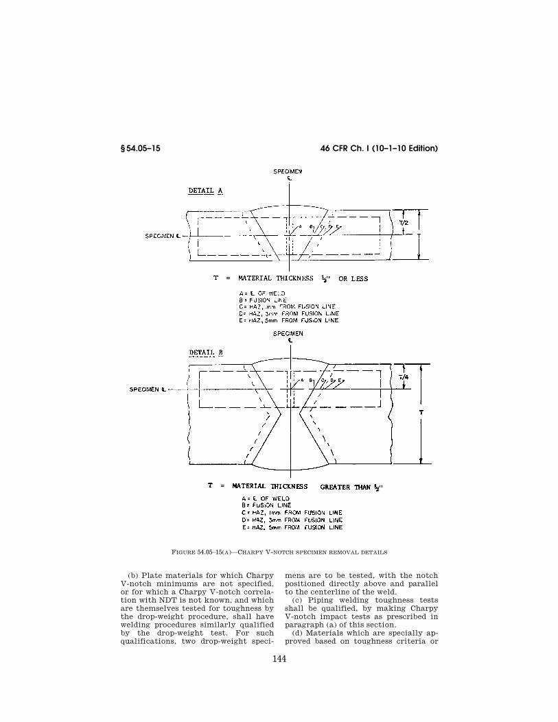
(a) Plate for which Charpy V-notch impact testing is required in the parent material and for which V-notch mini-ma are specified shall similarly have welding procedures qualified for tough-ness by Charpy V-notch testing. For these tests, the test plates shall be ori-ented with their final rolling direction parallel to the weld axis (i.e., so that transverse impact specimens result),
and with the V-notch normal to the plate surface. The sample weld joint preparation shall be the same as that used in production. The number of test specimens and the location of their notches shall be as shown in Figure 54.05–15(a) and as described in para-graphs (a) (1) through (5) of this sec-tion.
(1) Three specimens with the notch centered in the weld metal.
(2) Three specimens with the notch centered on the fusion line between parent plate and weld. (The fusion line may be identified by etching the speci-men with a mild reagent.)
(3) Three specimens with the notch centered in the heat affected zone, 1 mm from the fusion line.
(4) Same as paragraph (a)(3) of this section, but 3 mm from the fusion line.
(5) Same as paragraph (a)(3) of this section, but 5 mm from the fusion line.
VerDate Mar<15>2010 09:56 Dec 08, 2010 Jkt 220192 PO 00000 Frm 00153 Fmt 8010 Sfmt 8010 Y:\SGML\220192.XXX 220192jdjo
nes
on D
SK
8KY
BLC
1PR
OD
with
CF
R
144
46 CFR Ch. I (10–1–10 Edition) § 54.05–15
FIGURE 54.05–15(A)—CHARPY V-NOTCH SPECIMEN REMOVAL DETAILS
(b) Plate materials for which Charpy V-notch minimums are not specified, or for which a Charpy V-notch correla-tion with NDT is not known, and which are themselves tested for toughness by the drop-weight procedure, shall have welding procedures similarly qualified by the drop-weight test. For such qualifications, two drop-weight speci-
mens are to be tested, with the notch positioned directly above and parallel to the centerline of the weld.
(c) Piping welding toughness tests shall be qualified, by making Charpy V-notch impact tests as prescribed in paragraph (a) of this section.
(d) Materials which are specially ap-proved based on toughness criteria or
VerDate Mar<15>2010 09:56 Dec 08, 2010 Jkt 220192 PO 00000 Frm 00154 Fmt 8010 Sfmt 8010 Y:\SGML\220192.XXX 220192 EC
01F
E91
.020
jdjo
nes
on D
SK
8KY
BLC
1PR
OD
with
CF
R

145
Coast Guard, Dept. of Homeland Security § 54.05–16
tests, other than those discussed in paragraphs (a) and (b) of this section, shall have welding procedures tested and qualified for toughness as deemed appropriate and necessary by the Com-mandant.
(e) In the case of stainless steels, weld procedure toughness tests may be limited to weld metal only if this is all that is required by § 54.25–15.
§ 54.05–16 Production toughness test-ing.
(a) For vessels of welded construc-tion, production toughness test plates shall be prepared for each 50 feet of lon-gitudinal and circumferential butt weld in each Class I-L vessel, or for each 150 feet in each Class II-L vessel, except for material other than stain-less steel that is exempted from impact test requirements by this subchapter. In the case of stainless steels, weld pro-duction toughness tests may be limited to weld metal only if this is all that is required be § 54.25–15. The test-plate thickness shall be the same as that of the vessel wall at the location of the production weld being sampled. The test plates shall be prepared, wherever possible, as run-off tabs attached at the ends of weld butts or seams. The roll-ing direction of the run-off tabs should be oriented parallel to the rolling di-rection of the adjacent production ma-terial. The test-plate material shall be taken from one of the heats of material used in the vessel, and both the elec-trodes and welding procedures shall be the same as used in the fabrication of the vessel. From each test plate, one set of three Charpy impact bars or two drop-weight specimens, as applicable according to the test used in procedure qualification, shall be taken transverse to the weld axis. For Charpy V-notch specimens, the notch shall be normal to the material surface and its location alternated (approximately) on succes-sive tests between the weld metal and heat affected zone. Thus, approxi-mately half of all weld production im-pact tests will be of weld metal and half of heat affected zone material. For the weld metal tests, the V-notch is to be centered between the fusion lines. For the heat affected zone tests, the notch is to be centered so as to sample, as nearly as practicable, the most crit-
ical location for toughness observed in the weld procedure qualification tests. Where the drop weight specimen is used in production weld testing, it shall be prepared in the same manner as specified for procedure qualification testing, § 54.05–15(b).
(b) For vessels not exceeding 5 cubic feet in volume, one set of impact speci-mens, or two drop-weight specimens, as applicable according to the test used in procedure qualification, may represent all vessels from the same heat of mate-rial not in excess of 100 vessels, or one heat-treatment furnace batch. In addi-tion, when such vessels are welded, one weld test plate made from one of the heats of material used, and two sets of impact specimens or two drop-weight specimens, as applicable, cut there-from, may represent the weld metal in the smallest of: One lot of 100 vessels or less; or each heat-treatment furnace batch; or each 50 feet of welding for Class I-L vessels; or each 150 feet of welding for Class II-L vessels.
(c) For several vessels or parts of ves-sels being welded in succession, the plate thickness of which does not vary by more than one-fourth inch, and which are made of the same grade of material, a test plate shall be furnished for each 50 feet of welding for Class I- L vessels or 150 feet of welding for Class II-L vessels. For each 50- or 150- foot increment of weld, as applicable, the test plates shall be prepared at the time of fabrication of the first vessel involving that increment.
(d) The test plates and any other test material from which toughness test specimens are cut shall be given the same heat-treatment as the production material they represent. Test speci-mens representing other material than the weld toughness test plates shall preferably be cut from a part of the vessel material but may be cut from like material that has been heat-treat-ed within the temperature range speci-fied by the producer in treating the ac-tual vessel material.
(e) For nonpressure vessel type tanks and associated secondary barriers, as defined in § 38.05–4, subchapter D (Tank Vessels) of this chapter, production toughness test plates shall be prepared in accordance with paragraphs (a) and (d) of this section. One set of toughness
VerDate Mar<15>2010 09:56 Dec 08, 2010 Jkt 220192 PO 00000 Frm 00155 Fmt 8010 Sfmt 8010 Y:\SGML\220192.XXX 220192jdjo
nes
on D
SK
8KY
BLC
1PR
OD
with
CF
R

146
46 CFR Ch. I (10–1–10 Edition) § 54.05–17
test plates shall be prepared for each 165 feet (50 meters) of production butt type welds.
§ 54.05–17 Weld toughness test accept-ance criteria.
(a) For Charpy V-notch impact tests the energy absorbed in both the weld metal and heat affected zone impact tests in weld qualification and produc-tion shall be:
(1) For weld metal specimens, not less than the transverse values re-quired for the parent material.
(2) For heat affected zone specimens, when the specimens are transversely oriented, not less than the transverse values required for the parent mate-rial.
(3) For heat affected zone specimens, when the specimens are longitudinally oriented, not less than 1.5 times the transverse values required for the par-ent material.
(b) For drop-weight tests both speci-mens from each required set shall ex-hibit a no-break performance.
[CGFR 68–82, 33 FR 18828, Dec. 18, 1968, as amended by CGD 73–254, 40 FR 40164, Sept. 2, 1975]
§ 54.05–20 Impact test properties for service of 0 ≥F and below.
(a) Test energy. The impact energies of each set of transverse Charpy speci-mens may not be less than the values shown in Table 54.05–20(a). Only one specimen in a set may be below the re-quired average and the value of that specimen must be above the minimum impact value permitted on one speci-men only. See § 54.05–5(c) for retest re-quirements.
TABLE 54.05–20(a)—CHARPY V-NOTCH IMPACT REQUIREMENTS
Size of specimen
Minimum impact value required for average of each set of 3 speci-
mens foot- pounds 1
Minimum impact value permitted on
one specimen only of a set, foot-
pounds
10 × 10 mm ........... 20.0 13.5 10 × 7.5 mm .......... 16.5 11.0 10 × 5 mm ............. 13.5 9.0 10 × 2.5 mm .......... 10.0 6.5
1 Straight line interpolation for intermediate values is permitted.
(b) Transversely oriented Charpy V- notch impact specimens of ASTM A 203
(incorporated by reference, see § 54.01–1) nickel steels must exhibit energies not less than the values shown in § 54.05–20 (a). Requirements for 9 percent nickel steels are contained in § 54.25–20. Other nickel alloy steels, when specially ap-proved by the Commandant, must ex-hibit a no-break performance when tested in accordance with the drop weight procedure. If, for such mate-rials, there are data indicating suitable correlation with drop-weight tests, Charpy V-notch tests may be specially considered by the Commandant in lieu of drop-weight tests. If the drop-weight test cannot be performed because of material thickness limitations (less than one-half inch), or product shape, or is otherwise inapplicable (because of heat treatment, chemistry etc.) other tests or test criteria will be specified by the Commandant.
(c) Where sufficient data are avail-able to warrant such waiver, the Com-mandant may waive the requirements for toughness testing austenitic stain-less steel materials. Where required, austenitic stainless steels are to be tested using the drop-weight procedure and must exhibit a no-break perform-ance. Where data are available indi-cating suitable correlation of Charpy V-notch results with drop-weight NDT or no-break performance, Charpy V- notch tests may be specially considered by the Commandant in lieu of dropweight tests. If the dropweight test cannot be performed because of material thickness limitations (less than one-half inch), or product shape, or is otherwise inapplicable (because of heat treatment, chemistry, etc.) other tests and/or test criteria will be speci-fied by the Commandant.
[CGD 73–254, 40 FR 40164, Sept. 2, 1975, as amended by USCG–2000–7790, 65 FR 58460, Sept. 29, 2000]
§ 54.05–25 [Reserved]
§ 54.05–30 Allowable stress values at low temperatures.
(a) The Coast Guard will give consid-eration to the enhanced yield and ten-sile strength properties of ferrous and nonferrous materials at low tempera-ture for the purpose of establishing al-lowable stress values for service tem-perature below 0 °F.
VerDate Mar<15>2010 09:56 Dec 08, 2010 Jkt 220192 PO 00000 Frm 00156 Fmt 8010 Sfmt 8010 Y:\SGML\220192.XXX 220192jdjo
nes
on D
SK
8KY
BLC
1PR
OD
with
CF
R

147
Coast Guard, Dept. of Homeland Security § 54.10–5
(b) The use of such allowable stress values must be specially approved by the Coast Guard for each application. Further information may be obtained by writing to the Coast Guard CG–521.
(c) Submittals must include informa-tion and calculations specified by the Coast Guard CG–521 to demonstrate that the allowable stress for the mate-rial cannot be exceeded under any pos-sible combination of vessel loads and metal temperature.
[CGD 73–133R, 39 FR 9179, Mar. 8, 1974, as amended by CGD 82–063b, 48 FR 4781, Feb. 3, 1983; CGD 95–072, 60 FR 50462, Sept. 29, 1995; CGD 96–041, 61 FR 50727, 50728, Sept. 27, 1996; USCG–2009–0702, 74 FR 49228, Sept. 25, 2009]
Subpart 54.10—Inspection, Reports, and Stamping
§ 54.10–1 Scope (modifies UG–90 through UG–103 and UG–115 through UG–120).
The inspection, tests, stamping, and reports for pressure vessels shall be as required by paragraphs UG–90 through UG–103 and UG–115 through UG–120 of section VIII of the ASME Boiler and Pressure Vessel Code (incorporated by reference; see 46 CFR 54.01–1) except as noted otherwise in this subpart.
[CGFR 68–82, 33 FR 18828, Dec. 18, 1968, as amended by USCG–2003–16630, 73 FR 65167, Oct. 31, 2008]
§ 54.10–3 Marine inspectors (replaces UG–90 and UG–91, and modifies UG–92 through UG–103).
(a) Only marine inspectors shall apply the Coast Guard Symbol. They will not apply any other code symbol to pressure vessels.
(b) All pressure vessels not exempted under provisions of § 54.01–15 shall be inspected by a marine inspector refer-ring to procedures outlined in UG–92 through UG–103 of section VIII of the ASME Boiler and Pressure Vessel Code (incorporated by reference; see 46 CFR 54.01–1) and §§ 50.30–10, 50.30–15, and 50.30–20 of this subchapter. The marine inspector will then stamp the vessel with the Coast Guard Symbol.
(c) Pressure vessels described in § 54.01–5(c)(3), except pressure vessels in systems regulated under § 58.60 of this chapter, must be visually examined by a marine inspector prior to installa-
tion. The marine inspector also reviews the associated plans and manufactur-ers’ data reports. If, upon inspection, the pressure vessel complies with the applicable requirements in § 54.01–5, the marine inspector stamps the pressure vessel with the Coast Guard Symbol.
[CGFR 68–82, 33 FR 18828, Dec. 18, 1968, as amended by CGD 77–147, 47 FR 21810, May 20, 1982; USCG–2003–16630, 73 FR 65167, Oct. 31, 2008]
§ 54.10–5 Maximum allowable working pressure (reproduces UG–98).
(a) The maximum allowable working pressure for a vessel is the maximum pressure permissible at the top of the vessel in its normal operating position at the designated coincident tempera-ture specified for that pressure. It is the least of the values found for max-imum allowable working pressure for any of the essential parts of the vessel by the principles given in paragraph (b) of this section and adjusted for any dif-ference in static head that may exist between the part considered and the top of the vessel. (See Appendix 3 of section VIII of the ASME Boiler and Pressure Vessel Code (incorporated by reference; see 46 CFR 54.01–1.)
(b) The maximum allowable working pressure for a vessel part is the max-imum internal or external pressure, in-cluding the static head hereon, as de-termined by the rules and formulas in section VIII of the ASME Boiler and Pressure Vessel Code, together with the effect of any combination of load-ings listed in UG–22 of section VIII of the ASME Boiler and Pressure Vessel Code (see 46 CFR 54.01–30) that are like-ly to occur, or the designated coinci-dent operating temperature, excluding any metal thickness specified as corro-sion allowance. (See UG–25 of section VIII of the ASME Boiler and Pressure Vessel Code.)
(c) Maximum allowable working pres-sure may be determined for more than one designated operating temperature, using for each temperature the applica-ble allowable stress value.
NOTE: Table 54.10–5 gives pictorially the interrelation among the various pressure levels pertinent to this part of the regula-tions. It includes reference to section VIII of the ASME Boiler and Pressure Vessel Code for definitions and explanations.
VerDate Mar<15>2010 09:56 Dec 08, 2010 Jkt 220192 PO 00000 Frm 00157 Fmt 8010 Sfmt 8010 Y:\SGML\220192.XXX 220192jdjo
nes
on D
SK
8KY
BLC
1PR
OD
with
CF
R

148
46 CFR Ch. I (10–1–10 Edition) § 54.10–5
VerDate Mar<15>2010 09:56 Dec 08, 2010 Jkt 220192 PO 00000 Frm 00158 Fmt 8010 Sfmt 8006 Y:\SGML\220192.XXX 220192 ER
31O
C08
.001
</G
PH
>
jdjo
nes
on D
SK
8KY
BLC
1PR
OD
with
CF
R

149
Coast Guard, Dept. of Homeland Security § 54.10–5
VerDate Mar<15>2010 09:56 Dec 08, 2010 Jkt 220192 PO 00000 Frm 00159 Fmt 8010 Sfmt 8010 Y:\SGML\220192.XXX 220192 ER
31O
C08
.002
</G
PH
>
jdjo
nes
on D
SK
8KY
BLC
1PR
OD
with
CF
R

150
46 CFR Ch. I (10–1–10 Edition) § 54.10–10
[USCG–2003–16630, 73 FR 65167, Oct. 31, 2008]
§ 54.10–10 Standard hydrostatic test (modifies UG–99).
(a) All pressure vessels shall satisfac-torily pass the hydrostatic test pre-scribed by this section, except those pressure vessels noted under § 54.10– 15(a).
(b) The hydrostatic-test pressure must be at least one and three-tenths (1.30) times the maximum allowable working pressure stamped on the pres-sure vessel, multiplied by the ratio of the stress value ‘‘S’’ at the test tem-perature to the stress value ‘‘S’’ at the design temperature for the materials of which the pressure vessel is con-structed. The values for ‘‘S’’ shall be taken from Tables UCS 23, UNF 23, UHA 23, or UHT 23 of section VIII of the ASME Boiler and Pressure Vessel Code (incorporated by reference, see 46 CFR 54.01–1). The value of ‘‘S’’ at test temperature shall be that taken for the material of the tabulated value of tem-perature closest to the test tempera-ture. The value of ‘‘S’’ at design tem-perature shall be as interpolated from the appropriate table. No ratio less than one shall be used. The stress re-sulting from the hydrostatic test shall not exceed 90 percent of the yield stress of the material at the test tempera-ture. External loadings which will exist in supporting structure during the hy-drostatic test should be considered. The design shall consider the combined stress during hydrostatic testing due to pressure and the support reactions. This stress shall not exceed 90 percent of the yield stress of the material at the test temperature. In addition the adequacy of the supporting structure during hydrostatic testing should be considered in the design.
(c) The hydrostatic test pressure shall be applied for a sufficient period of time to permit a thorough examina-tion of all joints and connections. The test shall not be conducted until the vessel and liquid are at approximately the same temperature.
(d) Defects detected during the hy-drostatic test or subsequent examina-tion shall be completely removed and then inspected. Provided the marine in-spector gives his approval, they may then be repaired.
(e) Vessels requiring stress relieving shall be stress relieved after any weld-ing repairs have been made. (See UW–40 of section VIII of the ASME Boiler and Pressure Vessel Code.)
(f) After repairs have been made the vessel shall again be tested in the reg-ular way, and if it passes the test, the marine inspector may accept it. If it does not pass the test, the marine in-spector can order supplementary re-pairs, or, if in his judgment the vessel is not suitable for service, he may per-manently reject it.
[CGFR 68–82, 33 FR 18828, Dec. 18, 1968, as amended by USCG–2003–16630, 73 FR 65170, Oct. 31, 2008]
§ 54.10–15 Pneumatic test (modifies UG–100).
(a) Pneumatic testing of welded pres-sure vessels shall be permitted only for those units which are so designed and/ or supported that they cannot be safely filled with water, or for those units which cannot be dried and are to be used in a service where traces of the testing medium cannot be tolerated.
(b) Proposals to pneumatically test shall be submitted to the cognizant Of-ficer in Charge, Marine Inspection, for approval.
(c) Except for enameled vessels, for which the pneumatic test pressure shall be at least equal to, but need not exceed, the maximum allowable work-ing pressure to be marked on the ves-sel, the pneumatic test pressure shall be at least equal to one and one-tenth (1.10) times the maximum allowable working pressure to be stamped on the vessel multiplied by the lowest ratio (for the materials of which the vessel is constructed) of the stress value ‘‘S’’ for the test temperature of the vessel to the stress value ‘‘S’’ for the design temperature (see UG–21 of section VIII of the ASME Boiler and Pressure Ves-sel Code (incorporated by reference; see 46 CFR 54.01–1)). In no case shall the pneumatic test pressure exceed one and one-tenth (1.10) times the basis for cal-culated test pressure as defined in UA– 60(e) of section VIII of the ASME Boiler and Pressure Vessel Code.
(d) The pneumatic test of pressure vessels shall be accomplished as fol-lows:
VerDate Mar<15>2010 09:56 Dec 08, 2010 Jkt 220192 PO 00000 Frm 00160 Fmt 8010 Sfmt 8010 Y:\SGML\220192.XXX 220192jdjo
nes
on D
SK
8KY
BLC
1PR
OD
with
CF
R

151
Coast Guard, Dept. of Homeland Security § 54.10–20
(1) The pressure on the vessel shall be gradually increased to not more than half the test pressure.
(2) The pressure will then be in-creased at steps of approximately one- tenth the test pressure until the test pressure has been reached.
(3) The pressure will then be reduced to the maximum allowable working pressure of the vessel to permit exam-ination.
(e) Pressure vessels pneumatically tested shall also be leak tested. The test shall be capable of detecting leak-age consistent with the design require-ments of the pressure vessel. Details of the leak test shall be submitted to the Commandant for approval.
(f) After satisfactory completion of the pneumatic pressure test, the vessel may be stamped in accordance with § 54.10–20. A marine inspector shall ob-serve the pressure vessel in a loaded condition at the first opportunity fol-lowing the pneumatic test. The tank supports and saddles, connecting pip-ing, and insulation if provided shall be examined to determine if they are sat-isfactory and that no leaks are evident.
(g) The pneumatic test is inherently more hazardous than a hydrostatic test, and suitable precautions shall be taken to protect personnel and adja-cent property.
[CGFR 68–82, 33 FR 18828, Dec. 18, 1968, as amended by USCG–2003–16630, 73 FR 65170, Oct. 31, 2008]
§ 54.10–20 Marking and stamping.
(a) Pressure vessels (replaces UG–116, except paragraph (k), and UG–118). Pres-sure vessels that are required by § 54.10– 3 to be stamped with the Coast Guard Symbol must also be stamped with the following information:
(1) Manufacturer’s name and serial number.
(2) Coast Guard number, see § 50.10–30 of this subchapter.
(3) Coast Guard Symbol, which is af-fixed only by the marine inspector.
(4) Maximum allowable working pres-sure ll kPa (ll psig) at ll °C (ll
°F). (5) Class. (6) Minimum design metal tempera-
ture, if below ¥18 °C (0 °F).
(7) Water capacity in liters (U.S. gal-lons), if a cargo carrying pressure ves-sel.
(b) Multichambered pressure vessels (replaces UG–116(k)). In cases where more than one pressure vessel is in-volved in an integral construction, as with a heat exchanger, the manufac-turer may elect to class the component pressure vessels differently. In such cases he shall stamp the combined structures as required in paragraph (a) of this section with information for each pressure vessel. Where an item for stamping is identical for both vessels, as with name and address of manufac-turer, it need not be duplicated. How-ever, where differences exist, each value and the vessel to which it applies shall be clearly indicated.
(c) Stamping data (replaces UG–117). Except as noted in paragraph (d) of this section, the data shall be stamped di-rectly on the pressure vessel. The data shall be legibly stamped and shall not be obliterated during the service life of the pressure vessel. In the event that the portion of the pressure vessel upon which the data is stamped is to be insu-lated or otherwise covered, the data shall be reproduced on a metal name-plate. This plate shall be securely at-tached to the pressure vessel. The nameplate shall be maintained in a leg-ible condition such that it may be eas-ily read.
(1) Those parts of pressure vessels re-quiring Coast Guard shop inspection under this part which are furnished by other than the shop of the manufac-turer responsible for the completed vessel shall be stamped with the Coast Guard Symbol, the Marine Inspection Office identification letters (see § 50.10– 30 of this subchapter) and the word ‘‘Part’’, the manufacturer’s name and serial number, and the design pressure.
(d) Thin walled vessels (Modifies UG– 119). In lieu of direct stamping on the pressure vessel, the information re-quired by paragraph (a) of this section shall be stamped on a nameplate per-manently attached to the pressure ves-sel when the pressure vessel is con-structed of—
(1) Steel plate less than one-fourth inch thick; or
VerDate Mar<15>2010 09:56 Dec 08, 2010 Jkt 220192 PO 00000 Frm 00161 Fmt 8010 Sfmt 8010 Y:\SGML\220192.XXX 220192jdjo
nes
on D
SK
8KY
BLC
1PR
OD
with
CF
R

152
46 CFR Ch. I (10–1–10 Edition) § 54.10–25
(2) Nonferrous plate less than one- half inch thick.
[CGFR 68–82, 33 FR 18828, Dec. 18, 1968, as amended by CGFR 69–127, 35 FR 9977, June 17, 1970; CGD 72–206R, 38 FR 17226, June 29, 1973; CGD 77–147, 47 FR 21810, May 20, 1982; USCG– 2003–16630, 73 FR 65170, Oct. 31, 2008]
§ 54.10–25 Manufacturers’ data report forms (modifies UG–120).
(a) The Manufacturers’ data report form, as provided by the Coast Guard, shall be completed in duplicate and certified by the manufacturer for each pressure vessel required to be shop in-spected under these regulations. The original of this form shall be delivered to the Coast Guard inspector.
(b) Data forms for those parts of a pressure vessel requiring inspection, which are furnished by other than the shop of the manufacturer responsible for the completed unit, shall be exe-cuted in triplicate by the manufacturer of the parts. The original and one copy shall be delivered to the Coast Guard inspector who shall forward one copy of the report to the Officer in Charge, Ma-rine Inspection, having cognizance over the final assembly. These partial data reports, together with the final inspec-tion and tests, shall be the final Coast Guard inspector’s authority to apply the Coast Guard symbol and number. A final data report shall be executed by the manufacturer or assembler who completes the final assembly and tests.
(c) If a pressure vessel is required to be inspected in accordance with § 54.10– 3(c), the manufacturer’s data reports required by UG–120 must be made available to the Coast Guard inspector for review prior to inspection of the pressure vessel.
(Approved by the Office of Management and Budget under control number 2130–0181)
[CGFR 69–127, 35 FR 9977, June 17, 1970 as amended by CGD 77–147, 47 FR 21810, May 20, 1982]
Subpart 54.15—Pressure-Relief Devices
§ 54.15–1 General (modifies UG–125 through UG–137).
(a) All pressure vessels built in ac-cordance with applicable requirements in Division 1 of section VIII of the
ASME Code must be provided with pro-tective devices as indicated in UG–125 through UG–136 except as noted other-wise in this subpart.
(b) The markings shall be in accord-ance with this chapter for devices cov-ered by § 54.15–10.
[CGFR 68–82, 33 FR 18828, Dec. 18, 1968, as amended by CGD 88–032, 56 FR 35822, July 29, 1991; USCG–2003–16630, 73 FR 65170, Oct. 31, 2008]
§ 54.15–3 Definitions (modifies Appen-dix 3).
(a) Definitions applicable to this sub-part are in § 52.01–3 of this subchapter.
[CGFR 68–82, 33 FR 18828, Dec. 18, 1968, as amended by USCG–2003–16630, 73 FR 65170, Oct. 31, 2008]
§ 54.15–5 Protective devices (modifies UG–125).
(a) All pressure vessels must be pro-vided with protective devices. The pro-tective devices must be in accordance with the requirements of UG–125 through UG–136 of section VIII of the ASME Boiler and Pressure Vessel Code (incorporated by reference; see 46 CFR 54.01–1) except as modified in this sub-part.
(b) An unfired steam boiler evapo-rator or heat exchanger (see § 54.01–10) shall be equipped with protective de-vices as required by § 54.15–15.
(c) All pressure vessels other than unfired steam boilers shall be pro-tected by pressure-relieving devices that will prevent the pressure from ris-ing more than 10 percent above the maximum allowable working pressure, except when the excess pressure is caused by exposure to fire or other un-expected source of heat.
(d) Where an additional hazard can be created by exposure of a pressure vessel to fire or other unexpected sources of external heat (for example, vessels used to store liquefied flammable gases), supplemental pressure-relieving devices shall be installed to protect against excessive pressure. Such sup-plemental pressure-relieving devices shall be capable of preventing the pres-sure from rising more than 20 percent above the maximum allowable working pressure of the vessel. The minimum required relief capacities for com-pressed gas pressure vessels are given
VerDate Mar<15>2010 09:56 Dec 08, 2010 Jkt 220192 PO 00000 Frm 00162 Fmt 8010 Sfmt 8010 Y:\SGML\220192.XXX 220192jdjo
nes
on D
SK
8KY
BLC
1PR
OD
with
CF
R

153
Coast Guard, Dept. of Homeland Security § 54.15–10
under § 54.15–25. A single pressure-re-lieving device may be used to satisfy the requirements of this paragraph and paragraph (c) of this section, provided it meets the requirements of both para-graphs.
(e) Pressure-relieving devices should be selected on the basis of their in-tended service. They shall be con-structed, located, and installed so that they are readily accessible for inspec-tion and repair and so arranged that they cannot be readily rendered inoper-ative.
(f) Where pressure-indicating gages are used, they shall be chosen to be compatible with the pressure to be in-dicated. The size of the visual display, the fineness of graduations, and the orientation of the display will be con-sidered. In no case shall the upper range of the gage be less than 1.2 times nor more than 2 times the pressure at which the relieving device is set to function.
(g) The Commandant may authorize or require the use of a rupture disk in lieu of a relief or safety valve under certain conditions of pressure vessel use and design. See § 54.15–13.
(h) Vessels that are to operate com-pletely filled with liquid shall be equipped with liquid relief valves un-less otherwise protected against over-pressure.
(i) The protective devices required under paragraph (a) of this section shall be installed directly on a pressure vessel except when the source of pres-sure is external to the vessel, and is under such positive control that the pressure in the vessel cannot exceed the maximum allowable working pres-sure at the operating temperature ex-cept as permitted in paragraphs (c) and (d) of this section.
(j) Pressure-relieving devices shall be constructed of materials suitable for the pressure, temperature, and other conditions of the service intended.
(k) The opening through all pipes and fittings between a pressure vessel and its pressure-relieving device shall have at least the area of the pressure-reliev-ing device inlet, and in all cases shall have sufficient area so as not to unduly restrict the flow to the pressure-reliev-ing device. The opening in the vessel shall be designed to provide direct and
unobstructed flow between the vessel and its pressure-relieving device.
(l) Safety devices need not be pro-vided by the pressure vessel manufac-turer. However, overpressure protec-tion shall be provided prior to placing the vessel in service.
[CGFR 68–82, 33 FR 18828, Dec. 18, 1968, as amended by CGD 88–032, 56 FR 35822, July 29, 1991; CGD 95–012, 60 FR 48049, Sept. 18, 1995; USCG–2003–16630, 73 FR 65170, Oct. 31, 2008]
§ 54.15–10 Safety and relief valves (modifies UG–126).
(a) All safety and relief valves for use on pressure vessels or piping systems shall be designed to meet the protec-tion and service requirements for which they are intended and shall be set to relieve at a pressure which does not exceed the ‘‘maximum allowable working pressure’’ of the pressure ves-sel or piping system. Relief valves are not required to have huddling cham-bers for other than steam service. In addition, safety valves used on vessels in which steam is generated shall meet § 52.01–120 of this subchapter except § 52.01–120(a)(9). For steam service below 206 kPa (30 psig), bodies of safety valves may be made of cast iron. Safe-ty relief valves used in liquefied com-pressed gas service shall meet subpart 162.017 or 162.018 in subchapter Q (Spec-ifications) of this chapter as appro-priate.
(b) Pilot-valve control or other indi-rect operation of safety valves is not permitted unless the design is such that the main unloading valve will open automatically at not over the set pressure and will discharge its full rated capacity if some essential part of the pilot or auxiliary device should fail. All other safety and relief valves shall be of the direct spring loaded type.
(c) Safety and relief valves for steam or air service shall be provided with a substantial lifting device so that the disk can be lifted from its seat when the pressure in the vessel is 75 percent of that at which the valve is set to blow.
(d) Safety and relief valves for serv-ice other than steam and air need not be provided with a lifting device al-though a lifting device is desirable if
VerDate Mar<15>2010 09:56 Dec 08, 2010 Jkt 220192 PO 00000 Frm 00163 Fmt 8010 Sfmt 8010 Y:\SGML\220192.XXX 220192jdjo
nes
on D
SK
8KY
BLC
1PR
OD
with
CF
R

154
46 CFR Ch. I (10–1–10 Edition) § 54.15–13
the vapors are such that their release will not create a hazard.
(e) If the design of a safety or relief valve is such that liquid can collect on the discharge side of the disk, the valve shall be equipped with a drain at the lowest point where liquid can collect (for installation, see UG–134 of section VIII of section VIII of the ASME Boiler and Pressure Vessel Code (incorporated by reference; see 46 CFR 54.01–1).
(f) Cast iron may be employed in the construction of relief valves for pres-sures not exceeding 125 pounds per square inch and temperatures not ex-ceeding 450 °F. Seats or disks of cast iron are prohibited.
(g) The spring in a relief valve in service for pressures up to and includ-ing 250 pounds per square inch shall not be reset for any pressure more than 10 percent above or 10 percent below that for which the relief valve is marked. For higher pressures, the spring shall not be reset for any pressure more than 5 percent above or 5 percent below that for which the relief valve is marked.
(h) The rated relieving capacity of safety and relief valves for use on pres-sure vessels shall be based on actual flow test data and the capacity shall be certified by the manufacturer in ac-cordance with one of the following:
(1) 120 percent of the valve set pres-sure for valves rated in accordance with CGA S–1.2 (incorporated by ref-erence; see 46 CFR 54.01–1).
(2) 110 percent of the valve set pres-sure for valves rated in accordance with UG–131 of section VIII of Section VIII of the ASME Boiler and Pressure Vessel Code.
(3) 103 percent of the valve set pres-sure for steam in accordance with PG– 69 of section VIII of the ASME Boiler and Pressure Vessel Code.
[CGFR 68–82, 33 FR 18828, Dec. 18, 1968, as amended by CGD 81–79, 50 FR 9436, Mar. 8, 1985; USCG–2003–16630, 73 FR 65170, Oct. 31, 2008]
§ 54.15–13 Rupture disks (modifies UG– 127).
(a) Paragraph UG–127 of section VIII of the ASME Boiler and Pressure Ves-sel Code (incorporated by reference; see 46 CFR 54.01–1) provides for the use of rupture disks in series with spring loaded safety or relief valves.
(b) For certain pressure vessels con-taining substances which may render a relief or safety valve inoperative, or where the installation of a valve is con-sidered impractical, the Commandant may authorize or require the use of a rupture disk in parallel with or in lieu of a spring loaded safety or relief valve. These rupture disks shall:
(1) Comply with the general provi-sions of § 54.15–5 except as noted other-wise in this section;
(2) Have a capacity for discharge such that the volume of release is sufficient to prevent the internal pressure from exceeding 120 percent of the ‘‘max-imum allowable working pressure’’ with the pressure vessel exposed to fire conditions (see § 54.15–25); and,
(3) Operate at a pressure level which does not produce fatigue failure of the disk. The normal maximum operating pressure multiplied by 1.3 shall not ex-ceed the nominal disk burst pressure. (Notice that this restriction for protec-tion of the rupture disk will usually re-quire operation below the ‘‘maximum allowable working pressure’’ of the pressure vessel and therefore should be considered in design.)
(c) All disks shall be oriented so that if rupture occurs, the disk fragments and pressure vessel discharge will be directed away from operating per-sonnel and vital machinery.
[CGFR 68–82, 33 FR 18828, Dec. 18, 1968, as amended by USCG–2003–16630, 73 FR 65170, Oct. 31, 2008]
§ 54.15–15 Relief devices for unfired steam boilers, evaporators, and heat exchangers (modifies UG–126).
(a) An approved safety valve set to relieve at a pressure not exceeding the ‘‘maximum allowable working pres-sure’’ of the shell shall be fitted to all unfired steam boilers and evaporators except for evaporators of the atmos-pheric type designed for vapor dis-charge direct to a distiller with no shutoff valve in the discharge line. The distiller connected to atmospheric evaporators shall be fitted with a vent to prevent a buildup in pressure. In no case shall the vent be less than 11⁄2 inches in diameter. Evaporators oper-ating between atmospheric pressure and 15 p.s.i.g., may use a rupture disc as an alternative to the safety valve.
VerDate Mar<15>2010 09:56 Dec 08, 2010 Jkt 220192 PO 00000 Frm 00164 Fmt 8010 Sfmt 8010 Y:\SGML\220192.XXX 220192jdjo
nes
on D
SK
8KY
BLC
1PR
OD
with
CF
R

155
Coast Guard, Dept. of Homeland Security § 54.15–25
(b) Safety valves for use on pressure vessels in which steam or pressure is generated shall comply with the re-quirements of § 54.15–10. Rupture discs used in lieu of these safety valves, as provided for in paragraph (a) of this section, shall comply with the require-ments of § 54.15–13.
(c) The relieving capacity of evapo-rator safety valves required by para-graph (a) of this section shall be at least equal to the capacity of the ori-fice fitted in the steam supply to the evaporator. The orifice capacity shall be determined in accordance with the formula in paragraph (c) (1) or (2) of this section as appropriate:
(1) Where the set pressure of the evaporator shell safety valve is 58 per-cent or less than the setting of the safety valve in the steam supply: W=51.45AP
(2) Where the set pressure of the evaporator shell safety valve exceeds 58 percent of the setting of the safety valve on the steam supply:
W=105.3A√ P1(P¥P1)
where: W=The required orifice capacity, in pounds
per hour. A=Cross-sectional area of rounded entrance
orifice, in square inches. The orifice shall be installed near the steam inlet or the coils or tubes and where no orifice is em-ployed the area used in the formula shall be that of the inlet connection or manifold.
P=Set pressure of steam supply safety valve, in pounds per square inch, absolute.
P1=Set pressure of evaporator shell safety valve, in pounds per square inch, absolute.
(d) The relieving capacity of safety valves on unfired steam boilers shall not be less than the maximum gener-ating capacity of the unfired steam boiler as certified by the manufacturer.
(e) On new installations and where the orifice size of an existing unfired steam boiler or evaporator is increased, an accumulation test shall be made by closing all steam outlet connections except the safety valves for a period of five minutes. When conducting the ac-cumulation test, the water shall be at the normal operating level and the steam pressure shall be at the normal operating pressure, and while under this test the pressure shall not rise more than 6 percent above the safety valve setting.
(f) A heat exchanger with liquid in the shell and the heating medium in the tubes or coils, shall be fitted with a liquid relief valve meeting the re-quirement of § 54.15–5.
(g)(1) A heat exchanger with steam in the shell and liquid in the tubes or coils at a pressure exceeding that in the shell, shall have a liquid relief valve fitted to protect the shell against excess pressure.
(2) The discharge capacity of such re-lief valves shall be calculated on the basis of the discharge from one tube using the difference in pressures be-tween that in the shell and that in the tubes and shall be not less than that determined by the following formula:
Q=29.81KD2√ P1¥P2
where:
Q=Required relief valve discharge capacity, in gallons per minute, based on relief valve set pressure.
P1=Pressure in the tube or coils, in pounds per square inch.
P2=Set pressure of the shell relief valve, in pounds per square inch.
D=Internal diameter of the largest tube or coil, in inches.
K=Coefficient of discharge=0.62.
[CGFR 68–82, 33 FR 18828, Dec. 18, 1968, as amended by CGD 72–206R, 38 FR 17226, June 29, 1973]
§ 54.15–25 Minimum relief capacities for cargo tanks containing com-pressed or liquefied gas.
(a) Each tank shall be fitted with one or more safety relief valves designed, constructed, and flow tested in accord-ance with subpart 162.017 or 162.018 in subchapter Q (Specifications) of this chapter. Valves conforming to speci-fication subpart 162.017 shall be limited to use on tanks whose maximum allow-able working pressure is not in excess of 10 pounds per square inch. With spe-cific approval of the Commandant, such valves may be connected to the vessel in lieu of being directly fitted to the tanks.
(b) The discharge pressure and the maximum overpressure permitted shall be in accordance with § 54.15–5.
(c) The rate of discharge for heat input of fire must meet the following formula:
Q=FGA0.82
VerDate Mar<15>2010 09:56 Dec 08, 2010 Jkt 220192 PO 00000 Frm 00165 Fmt 8010 Sfmt 8010 Y:\SGML\220192.XXX 220192jdjo
nes
on D
SK
8KY
BLC
1PR
OD
with
CF
R

156
46 CFR Ch. I (10–1–10 Edition) § 54.15–25
1 Figure 54.15–25(c) shows a method of de-termining the side external surface area of a grouping of vertical pressure tanks.
where: Q=minimum required rate of discharge in
cubic meters (cubic feet) per minute of air at standard conditions 15 °C and 103 kPa (60 °F and 14.7 psia).
F=fire exposure factor for the following tank types:
F=1.0 for tanks without insulation located on the open deck.
F=0.5 for tanks on the open deck having in-sulation that has approved fire proofing, thermal conductance, and stability under fire exposure.
F=0.5 for uninsulated independent tasks in-stalled in holds.
F=0.2 for insulated independent tanks in holds or for uninsulated independent tanks in insulated holds.
F=0.1 for insulated independent tanks in inerted holds or for uninsulated inde-pendent tanks in inerted, insulated holds.
F=0.1 for membrane and semi-membrane tanks.
G=gas factor of:
" / )]
/ )]
G = [(177/LC) ( ZT
G = [(633,000/LC) ( ZT
M SI
M
units
English units"
where: L=latent heat of the material being vapor-
ized at the relieving conditions, in Kcal/kg (Btu per pound).
C=constant based on relation of specific heats (k), Table § 54.15–25(c) (if k is not known, C=.606(315)).
Z=compressibility factor of the gas at the re-lieving conditions (if not known, Z=1.0).
T=temperature in degrees K=(273 + degrees C) (R=(460 + degrees F)) at the relieving conditions (120% of the pressure at which the pressure relief valve is set).
M=molecular weight of the product. A=external surface area of the tank in m2
(sq. ft.) for the following tank types:
For a tank of a body of revolution shape: A=external surface area. For a tank other than a body of revolution
shape: A=external surface area less the projected
bottom surface area. For a grouping of pressure vessel tanks
having insulation on the vessel’s struc-ture:
A=external surface area of the hold with-out the projected bottom area.
For a grouping of pressure tanks having in-sulation on the tank:
A=external surface area of the pressure tanks excluding insulation, and without the projected bottom area.1
VerDate Mar<15>2010 09:56 Dec 08, 2010 Jkt 220192 PO 00000 Frm 00166 Fmt 8010 Sfmt 8010 Y:\SGML\220192.XXX 220192 ER
25S
E09
.062
</M
AT
H>
jdjo
nes
on D
SK
8KY
BLC
1PR
OD
with
CF
R

157
Coast Guard, Dept. of Homeland Security § 54.15–25
TABLE 54.15–25(c)—CONSTANT C
k C
1.00 ............................................ .606 (315) 1.02 ............................................ .611 (318) 1.04 ............................................ .615 (320) 1.06 ............................................ .620 (322) 1.08 ............................................ .624 (324) 1.10 ............................................ .628 (327) 1.12 ............................................ .633 (329) 1.14 ............................................ .637 (331) 1.16 ............................................ .641 (333) 1.18 ............................................ .645 (335) 1.20 ............................................ .649 (337) 1.22 ............................................ .652 (339) 1.24 ............................................ .658 (341) 1.26 ............................................ .660 (343) 1.28 ............................................ .664 (345) 1.30 ............................................ .667 (347) 1.32 ............................................ .671 (349) 1.34 ............................................ .674 (351) 1.36 ............................................ .677 (352) 1.38 ............................................ .681 (354) 1.40 ............................................ .685 (356) 1.42 ............................................ .688 (358) 1.44 ............................................ .691 (359) 1.46 ............................................ .695 (361) 1.48 ............................................ .698 (363) 1.50 ............................................ .701 (364) 1.52 ............................................ .704 (366) 1.54 ............................................ .707 (368) 1.56 ............................................ .710 (369) 1.58 ............................................ .713 (371) 1.60 ............................................ .716 (372) 1.62 ............................................ .719 (374) 1.64 ............................................ .722 (376) 1.66 ............................................ .725 (377) 1.68 ............................................ .728 (379) 1.70 ............................................ .731 (380) 1.72 ............................................ .734 (382) 1.74 ............................................ .736 (383) 1.76 ............................................ .739 (384) 1.78 ............................................ .742 (386) 1.80 ............................................ .745 (387)
TABLE 54.15–25(c)—CONSTANT C—Continued
k C
1.82 ............................................ .747 (388) 1.84 ............................................ .750 (390) 1.86 ............................................ .752 (391) 1.88 ............................................ .755 (392) 1.90 ............................................ .758 (394) 1.92 ............................................ .760 (395) 1.94 ............................................ .763 (397) 1.96 ............................................ .765 (398) 1.98 ............................................ .767 (399) 2.00 ............................................ .770 (400) 2.02 ............................................ .772 (401) 2.20 ............................................ .792 (412)
(c–1) For an independent tank that has a portion of the tank protruding above the open deck, the fire exposure factor must be calculated for the sur-face area above the deck and the sur-face area below the deck, and this cal-culation must be specially approved by the Commandant CG–521.
(d) In determining the total safety valve relieving capacity, the arrange-ment and location of the valves on the tank will be evaluated. The valves shall be placed so that a number of valves sufficient to provide the re-quired relieving capacity shall always be in communication with the cargo vapor phase. The possible motions which the tank may see in its intended service and attendant changes in cargo liquid level will be considered. Shut off valves shall not be installed between
VerDate Mar<15>2010 09:56 Dec 08, 2010 Jkt 220192 PO 00000 Frm 00167 Fmt 8010 Sfmt 8010 Y:\SGML\220192.XXX 220192 EC
01F
E91
.022
</G
PH
>
jdjo
nes
on D
SK
8KY
BLC
1PR
OD
with
CF
R

158
46 CFR Ch. I (10–1–10 Edition) § 54.20–1
the vessel and the safety relief valves. Manifolds for mounting multiple relief valves may be fitted with acceptable interlocking shut off valves so ar-ranged that the required capacity of discharge will be ‘‘lined up’’ at all times.
(e)(1) Each safety relief valve shall be tested in the presence of a marine in-spector before being placed in service except as noted otherwise in paragraph (e)(2) of this section. The test shall sat-isfactorily show that the valve will start to discharge at the required min-imum pressure.
(2) Each safety relief valve fitted with a breaking pin and rupture disk need not be tested in the presence of a marine inspector before being placed in service. In lieu thereof, a certificate shall be furnished with the valve at-tested to by the manufacturer that the test requirements of paragraph (e)(1) of this section have been met.
[CGFR 68–82, 33 FR 18828, Dec. 18, 1968, as amended by CGD 74–289, 44 FR 26007, May 3, 1979; CGD 82–063b, 48 FR 4781, Feb. 3, 1983; CGD 95–072, 60 FR 50462, Sept. 29, 1995; CGD 96–041, 61 FR 50728, Sept. 27, 1996; USCG–2004– 18884, 69 FR 58346, Sept. 30, 2004; USCG–2007– 29018, 72 FR 53965, Sept. 21, 2007; USCG–2009– 0702, 74 FR 49228, Sept. 25, 2009]
Subpart 54.20—Fabrication by Welding
§ 54.20–1 Scope (modifies UW–1 through UW–65).
(a) Pressure vessels and vessel parts that are fabricated by welding shall be as required by paragraphs UW–1 through UW–65 of section VIII of the ASME Boiler and Pressure Vessel Code (incorporated by reference; see 46 CFR 54.01–1) except as noted otherwise in this subchapter.
(b) [Reserved]
[CGFR 68–82, 33 FR 18828, Dec. 18, 1968, as amended by USCG–2003–16630, 73 FR 65170, Oct. 31, 2008]
§ 54.20–2 Fabrication for hazardous materials (replaces UW–2(a)).
(a) Pressure vessels containing haz-ardous materials as defined in § 150.115 of this chapter must be of the class and construction required by subchapter D, I, O, or, when not specified, of a class determined by the Commandant.
(b) Class III pressure vessels must not be used for the storage or stowage of hazardous materials unless there is specific authorization in subchapters D, I, or O.
[CGD 77–147, 47 FR 21810, May 20, 1982]
§ 54.20–3 Design (modifies UW–9, UW– 11(a), UW–13, and UW–16).
(a) Fabrication by welding shall be in accordance with the provisions of this part and with part 57 of this sub-chapter.
(b) Welding subject to UW–11(a) of section VIII of the ASME Boiler and Pressure Vessel Code (incorporated by reference; see 46 CFR 54.01–1) shall be modified as described in § 54.25–8 for ra-diographic examination.
(c) A butt welded joint with one plate edge offset, as shown in Figure UW– 13.1(k) of section VIII of the ASME Boiler and Pressure Vessel Code, may only be used for circumferential joints of Class II and Class III pressure ves-sels.
(d) Attachment welds for nozzles and other connections shall be in accord-ance with UW–16 of section VIII of the ASME Boiler and Pressure Vessel Code. When nozzles or connections are made to pressure vessels, as shown in Figure UW–16.1 (a) and (c) of the ASME Code, and are welded from one side only, backing strips shall be used unless it can be determined visually that a full penetration weld has been achieved.
(e) When fabricating by welding the minimum joint requirements shall be as specified under the column headed ‘‘minimum joint requirements’’ in Table 54.01–5(b) for various classes of pressure vessels.
(f) Joints in Class II or III pressure vessel cargo tanks must meet the fol-lowing:
(1) Category A and B joints must be type (1) or (2).
(2) Category C and D joints must have full penetration welds extending through the entire thickness of the vessel wall or nozzle wall.
[CGFR 68–82, 33 FR 18828, Dec. 18, 1968, as amended by CGD 77–147, 47 FR 21810, May 20, 1982; CGD 85–061, 54 FR 50964, Dec. 11, 1989; USCG–2003–16630, 73 FR 65170, Oct. 31, 2008]
VerDate Mar<15>2010 09:56 Dec 08, 2010 Jkt 220192 PO 00000 Frm 00168 Fmt 8010 Sfmt 8010 Y:\SGML\220192.XXX 220192jdjo
nes
on D
SK
8KY
BLC
1PR
OD
with
CF
R

159
Coast Guard, Dept. of Homeland Security § 54.25–10
§ 54.20–5 Welding qualification tests and production testing (modifies UW–26, UW–28, UW–29, UW–47, and UW–48).
(a) Performance and procedure quali-fication. No production welding shall be done until welding procedures and welders have been qualified in accord-ance with part 57 of this subchapter.
(b) Tests. Production tests are re-quired in accordance with § 57.06–1 of this subchapter.
[CGFR 68–82, 33 FR 18828, Dec. 18, 1968, as amended by CGFR 69–127, 35 FR 9977, June 17, 1970]
Subpart 54.23—Fabrication by Brazing
§ 54.23–1 Scope (modifies UB–1).
(a) Fabrication by brazing shall be in accordance with the provisions of this part and with part 57 of this sub-chapter.
[CGFR 69–127, 35 FR 9977, June 17, 1970]
Subpart 54.25—Construction With Carbon, Alloy, and Heat Treated Steels
§ 54.25–1 Scope.
The carbon, alloy, and heat treated steels used in construction of pressure vessels and parts shall be as indicated in section VIII of the ASME Boiler and Pressure Vessel Code (incorporated by reference; see 46 CFR 54.01–1) except as noted otherwise in this subpart.
[CGFR 68–82, 33 FR 18828, Dec. 18, 1968, as amended by USCG–2003–16630, 73 FR 65170, Oct. 31, 2008]
§ 54.25–3 Steel plates (modifies UCS–6).
The steels listed in UCS–6(b) of sec-tion VIII of the ASME Boiler and Pres-sure Vessel Code (incorporated by ref-erence; see 46 CFR 54.01–1) will be al-lowed only in Class III pressure vessels (see Table 54.01–5(b)).
[USCG–2003–16630, 73 FR 65170, Oct. 31, 2008]
§ 54.25–5 Corrosion allowance.
The corrosion allowance must be as required in 46 CFR 54.01–35.
[USCG–2003–16630, 73 FR 65170, Oct. 31, 2008]
§ 54.25–7 Requirement for postweld heat treatment (modifies UCS–56).
(a) Postweld heat treatment is re-quired for all carbon and low alloy steel Class I, I-L, and II-L vessels re-gardless of thickness. (Refer to Table 54.01–5(b) for applicable requirements.)
(b) Cargo tanks which are fabricated of carbon or low alloy steel as Class II pressure vessels, designed for pressures exceeding 100 pounds per square inch gage and used in the storage or trans-portation of liquefied compressed gases shall be postweld heat treated regard-less of thickness.
[CGFR 69–127, 35 FR 9977, June 17, 1970]
§ 54.25–8 Radiography (modifies UW– 11(a), UCS–57, UNF–57, UHA–33, and UHT–57).
(a) Full radiography is required for all Class I and Class I-L vessels regard-less of thickness. (Refer to Table 54.01– 5(b) for applicable requirements.)
(b) Class II-L vessels shall be spot radiographed. The exemption provided in UW–11(c) of section VIII of the ASME Boiler and Pressure Vessel Code (incorporated by reference; see 46 CFR 54.01–1) does not apply. (Refer to Table 54.01–5(b) for applicable requirements.)
(c) Each butt welded joint in a Class II or III pressure vessel cargo tank must be spot radiographed, in accord-ance with UW–52, regardless of diame-ter or thickness, and each weld inter-section or crossing must be radiographed for a distance of at least 10 thicknesses from the intersection.
[CGFR 68–82, 33 FR 18828, Dec. 18, 1968, as amended by CGD 85–061, 54 FR 50964, Dec. 11, 1989; USCG–2003–16630, 73 FR 65170, Oct. 31, 2008]
§ 54.25–10 Low temperature oper-ation—ferritic steels (replaces UCS– 65 through UCS–67).
(a) Scope. (1) This section contains re-quirements for pressure vessels and nonpressure vessel type tanks and as-sociated secondary barrier, as defined in § 38.05–4 and § 154.7 of this chapter, and their parts constructed of carbon and alloy steels which are stressed at operating or hydrostatic test tempera-tures below 0 °F.
(2) The service temperature is the minimum temperature of a product at which it may be contained, loaded and/
VerDate Mar<15>2010 09:56 Dec 08, 2010 Jkt 220192 PO 00000 Frm 00169 Fmt 8010 Sfmt 8010 Y:\SGML\220192.XXX 220192jdjo
nes
on D
SK
8KY
BLC
1PR
OD
with
CF
R

160
46 CFR Ch. I (10–1–10 Edition) § 54.25–10
or transported. However, the service temperature shall in no case be taken higher than given by the following for-mula:
ts=tw¥0.25(tw¥tB)
where: ts=Service temperature. tw=Boiling temperature of gas at normal
working pressure of container but not higher than +32 °F.
tB=Boiling temperature of gas at atmos-pheric pressure.
Only temperatures due to refrigerated service usually need to be considered in determining the service temperature, except pressure vessel type cargo tanks operating at ambient temperatures must meet paragraph (d) of this sec-tion. ‘‘Refrigerated service’’, as used in this paragraph, means a service in which the temperature is controlled by the process and not by atmospheric conditions.
(b) Specifications. Materials used in the construction of vessels to operate below 0 °F. (but not below the des-ignated minimum service temperature) shall conform to a specification given in Table UCS–23 in section VIII of the ASME Boiler and Pressure Vessel Code (incorporated by reference; see 46 CFR 54.01–1) and the following additional re-quirements:
NOTE: For high alloy steels refer to § 54.25– 15. For heat treated steels refer to § 54.25–20.
(1)(i) For minimum service tempera-tures not lower than ¥67 °F., ferritic steels shall be made with fine grain practice and shall have an austenitic grain size of 5 or finer, and shall be normalized. Consideration will be given to other heat treatments. Refer to § 57.03–1(d) of this subchapter. Plate for pressure vessel applications shall con-form to the requirements of ASTM A 20 (incorporated by reference, see § 54.01– 1). It may be produced by the open hearth, basic oxygen or electric fur-nace process and shall conform to the requirements of Table 54.25–10(b)(1). (Other alloying elements may only be present in trace amounts.)
(ii) Mechanical properties shall be within the following limits: Ultimate strength ......... —58,000 1–85,000 1 p.s.i. Yield strength ............... —Minimum 35,000 p.s.i.
—Maximum 80 percent of ultimate. Elongation minimum .... —20 percent in 8 inches, or
—24 percent in 2 inches, or —22 percent in 5.65 √A, where ‘‘A’’
is the test specimen cross sec-tional area.
TABLE 54.25–10(b)(1)
Minimum service 1 temperature °F
Max. C 1 percent
Manganese range 1 per-
cent
¥30 ........................................... 0.20 0.70–1.35 ¥50 ........................................... .16 1.15–1.50 ¥67 ........................................... .12 1.30–1.60
1 At service temperatures intermediate between those speci-fied, intermediate amounts of carbon and manganese will be allowed (in proportion to the actual service temperature vari-ation from that listed), provided all other chemical and me-chanical properties specified for steels in this temperature range are satisfied.
Range per-cent
Si .......................................................................... 0.10–0.50
Maximum
S ........................................................................... 0.035 P ........................................................................... 0.035 Ni .......................................................................... 0.80 Cr ......................................................................... 0.25 Mo ........................................................................ 0.08 Cu ........................................................................ 0.035 Nb ........................................................................ 0.05 V ........................................................................... 0.08
(2) For minimum service temperature below ¥67 °F., but not below the des-ignated minimum service temperature, ferritic steels shall be normalized, low carbon, fully killed, fine grain, nickel alloy type, conforming to any one of the specifications in Table 54.25– 10(b)(2). Consideration will be given to other heat treatments. Refer to § 57.03– 1(d) of this subchapter for quenched and tempered steels. The ultimate and yield strengths shall be as shown in the applicable specification and shall be suitable to the design stress levels adopted. The service temperature shall not be colder than the minimum speci-fied in Table 54.25–10(b)(2) for each steel.
TABLE 54.25–10(b)(2)
Steel Minimum service temperature
A–203, 21⁄4 percent, Ni, normalized.
¥80 °F. for Grade A. ¥75 °F. for Grade B.
A–203, 31⁄2 percent, Ni, normalized.
¥130 °F. for Grade D. ¥110 °F. for Grade E.
5 percent Ni, normalized Dependent on chemical and physical properties.
(3) The materials permitted under paragraphs (b) (1) and (2) of this section
VerDate Mar<15>2010 09:56 Dec 08, 2010 Jkt 220192 PO 00000 Frm 00170 Fmt 8010 Sfmt 8010 Y:\SGML\220192.XXX 220192jdjo
nes
on D
SK
8KY
BLC
1PR
OD
with
CF
R

161
Coast Guard, Dept. of Homeland Security § 54.25–15
shall be tested for toughness in accord-ance with and shall satisfy the applica-ble requirements of subpart 54.05.
(4) Welded pressure vessels or non-pressure vessel type tanks and associ-ated secondary barriers, as defined in § 38.05–4 of subchapter D (Tank Vessels) of this chapter shall meet the tough-ness requirements of subparts 57.03 and 57.06 of this subchapter with regard to weld procedure qualifications and pro-duction testing.
(5) The material manufacturer’s iden-tification marking required by the ma-terial specification shall not be die- stamped on plate material less than one-fourth inch in thickness.
(c) Design. Pressure vessels must meet the requirements for Class I-L and II-L construction. (See Table 54.01– 5(b) for applicable requirements). Ex-cept as permitted by § 54.05–30, the al-lowable stress values used in the design of low temperature pressure vessels may not exceed those given in Table UCS–23 of section VIII of the ASME Boiler and Pressure Vessel Code for temperatures of 0 °F. to 650 °F. For ma-terials not listed in this Table allow-able stress values are determined in ac-cordance with Appendix P of Section VIII of the ASME Boiler and Pressure Vessel Code.
(d) Weldments and all materials used in pressure vessel type cargo tanks op-erating at ambient temperatures and constructed of materials listed in Table UCS–23 must pass Charpy impact tests in accordance with UG–84 at a temperature of ¥20 °F or colder, except as provided by paragraphs (d)(1), (d)(2), and (d)(3) of this section.
(1) Charpy impact tests are not re-quired for any of the following ASTM materials if the thickness for each is 5⁄8 inch or less, unless otherwise indi-cated:
(i) A–182, normalized and tempered. (ii) A–302, Grades C and D. (iii) A–336, Grades F21 and F22 that
are normalized and tempered. (iv) A–387, Grades 21 and 22 that are
normalized and tempered. (v) A–516, Grades 55 and 60. (vi) A–533, Grades B and C. (vii) All other plates, structural
shapes and bars, and other product forms, except for bolting, if produced to a fine grain practice and normalized.
(2) Charpy impact tests are not re-quired for any of the following ASTM materials if the thickness for each is 11⁄4 inch or less:
(i) A–203. (ii) A–508, Class 1. (iii) A–516, normalized. (iv) A–524. (v) A–537. (vi) A–612, normalized. (vii) A–662, normalized. (viii) A–724, normalized. (3) Charpy impact tests are not re-
quired for any of the following bolt ma-terials:
(i) A–193, Grades B5, B7, B7M, and B16.
(ii) A–307, Grade B (iii) A–325, Type 1. (iv) A–449.
[CGFR 68–82, 33 FR 18828, Dec. 18, 1968, as amended by CGFR 69–127, 35 FR 9977, June 17, 1970; CGD 73–133R, 39 FR 9178, Mar. 8, 1974; CGD 74–289, 44 FR 26007, May 3, 1979; CGD 77– 069, 52 FR 31626, Aug. 21, 1987; CGD 85–061, 54 FR 50964, Dec. 11, 1989; USCG–1999–5151, 64 FR 67178, Dec. 1, 1999; USCG–2000–7790, 65 FR 58460, Sept. 29, 2000; USCG–2003–16630, 73 FR 65170, Oct. 31, 2008]
§ 54.25–15 Low temperature oper-ation—high alloy steels (modifies UHA–23(b) and UHA–51).
(a) Toughness tests for the materials listed in UHA–51(a) in section VIII of the ASME Boiler and Pressure Vessel Code (incorporated by reference; see 46 CFR 54.01–1) for service temperatures below ¥425 °F., UHA–51(b)(1) through (5) for service temperatures below 0 °F., and UHA–51(c) for all service tempera-tures, shall be performed in accordance with the requirements of subpart 54.05. These requirements are also applicable to nonpressure vessel type, low tem-perature tanks and associated sec-ondary barriers, as defined in § 38.05–4 in subchapter D (Tank Vessels) of this chapter. Such tests are required re-gardless of the vessel’s design stress. Service temperature is defined in § 54.25–10(a)(2).
(b) Materials for pressure vessels with service temperatures below ¥320 °F. shall be of the stabilized or low car-bon (less than 0.10 percent) austenitic stainless steel type, produced accord-ing to the applicable specifications of Table UHA–23 of section VIII of the ASME Boiler and Pressure Vessel Code.
VerDate Mar<15>2010 09:56 Dec 08, 2010 Jkt 220192 PO 00000 Frm 00171 Fmt 8010 Sfmt 8010 Y:\SGML\220192.XXX 220192jdjo
nes
on D
SK
8KY
BLC
1PR
OD
with
CF
R
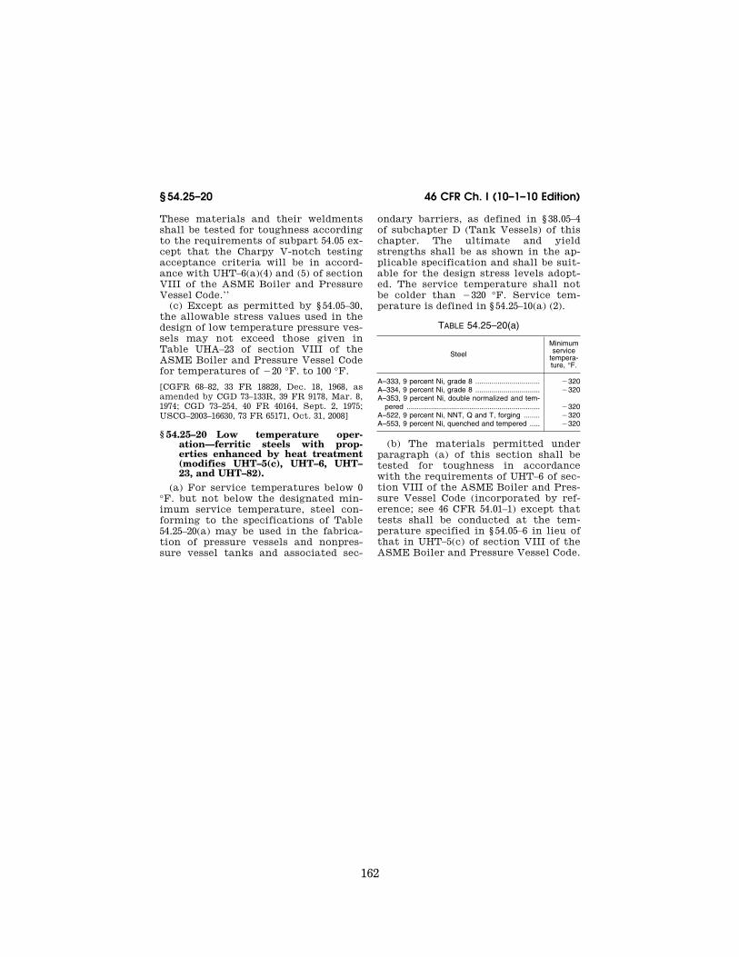
162
46 CFR Ch. I (10–1–10 Edition) § 54.25–20
These materials and their weldments shall be tested for toughness according to the requirements of subpart 54.05 ex-cept that the Charpy V-notch testing acceptance criteria will be in accord-ance with UHT–6(a)(4) and (5) of section VIII of the ASME Boiler and Pressure Vessel Code.’’
(c) Except as permitted by § 54.05–30, the allowable stress values used in the design of low temperature pressure ves-sels may not exceed those given in Table UHA–23 of section VIII of the ASME Boiler and Pressure Vessel Code for temperatures of ¥20 °F. to 100 °F.
[CGFR 68–82, 33 FR 18828, Dec. 18, 1968, as amended by CGD 73–133R, 39 FR 9178, Mar. 8, 1974; CGD 73–254, 40 FR 40164, Sept. 2, 1975; USCG–2003–16630, 73 FR 65171, Oct. 31, 2008]
§ 54.25–20 Low temperature oper-ation—ferritic steels with prop-erties enhanced by heat treatment (modifies UHT–5(c), UHT–6, UHT– 23, and UHT–82).
(a) For service temperatures below 0 °F. but not below the designated min-imum service temperature, steel con-forming to the specifications of Table 54.25–20(a) may be used in the fabrica-tion of pressure vessels and nonpres-sure vessel tanks and associated sec-
ondary barriers, as defined in § 38.05–4 of subchapter D (Tank Vessels) of this chapter. The ultimate and yield strengths shall be as shown in the ap-plicable specification and shall be suit-able for the design stress levels adopt-ed. The service temperature shall not be colder than ¥320 °F. Service tem-perature is defined in § 54.25–10(a) (2).
TABLE 54.25–20(a)
Steel
Minimum service
tempera-ture, °F.
A–333, 9 percent Ni, grade 8 ................................ ¥320 A–334, 9 percent Ni, grade 8 ................................ ¥320 A–353, 9 percent Ni, double normalized and tem-
pered .................................................................. ¥320 A–522, 9 percent Ni, NNT, Q and T, forging ........ ¥320 A–553, 9 percent Ni, quenched and tempered ..... ¥320
(b) The materials permitted under paragraph (a) of this section shall be tested for toughness in accordance with the requirements of UHT–6 of sec-tion VIII of the ASME Boiler and Pres-sure Vessel Code (incorporated by ref-erence; see 46 CFR 54.01–1) except that tests shall be conducted at the tem-perature specified in § 54.05–6 in lieu of that in UHT–5(c) of section VIII of the ASME Boiler and Pressure Vessel Code.
VerDate Mar<15>2010 09:56 Dec 08, 2010 Jkt 220192 PO 00000 Frm 00172 Fmt 8010 Sfmt 8010 Y:\SGML\220192.XXX 220192jdjo
nes
on D
SK
8KY
BLC
1PR
OD
with
CF
R

163
Coast Guard, Dept. of Homeland Security § 54.25–25
(c) The qualification of welding pro-cedures, welders and weld-production testing for the steels of Table 54.25– 20(a) must conform to the requirements of part 57 of this subchapter and to those of subpart 54.05 of this part ex-cept that the acceptance criteria for Charpy V-notch testing must be in ac-cordance with UHT–6(a)(4) of section VIII of the ASME Boiler and Pressure Vessel Code.
(d) The values of absorbed energy in foot-pounds and of fracture appearance in percentage shear, which are recorded for information when complying with paragraphs (b) and (c) of this section shall also be reported to the marine in-spector or the Commandant, as appli-cable.
(e) Except as permitted by § 54.05–30, the allowable stress values may not ex-ceed those given in Table UHT–23 of section VIII of the ASME Boiler Pres-sure and Vessel Code for temperatures of 150 °F and below.
[CGFR 68–82, 33 FR 18828, Dec. 18, 1968, as amended by CGD 73–133R, 39 FR 9179, Mar. 8, 1974; USCG–2000–7790, 65 FR 58460, Sept. 29, 2000; USCG–2003–16630, 73 FR 65171, Oct. 31, 2008]
§ 54.25–25 Welding of quenched and tempered steels (modifies UHT–82).
(a) The qualification of welding pro-cedures, welders, and weld-production testing must conform to the require-ments of part 57 of this subchapter. The requirements of 46 CFR 57.03–1(d)
VerDate Mar<15>2010 09:56 Dec 08, 2010 Jkt 220192 PO 00000 Frm 00173 Fmt 8010 Sfmt 8010 Y:\SGML\220192.XXX 220192 EC
01F
E91
.023
</G
PH
>
jdjo
nes
on D
SK
8KY
BLC
1PR
OD
with
CF
R

164
46 CFR Ch. I (10–1–10 Edition) § 54.30–1
apply to welded pressure vessels and non-pressure vessel type tanks of quenched and tempered steels other than 9-percent nickel.
(b) [Reserved]
[CGFR 68–82, 33 FR 18828, Dec. 18, 1968, as amended by USCG–2003–16630, 73 FR 65171, Oct. 31, 2008]
Subpart 54.30—Mechanical Stress Relief
§ 54.30–1 Scope. (a) Certain pressure vessels may be
mechanically stress relieved in accord-ance with the requirements in this sub-part.
(b) [Reserved]
§ 54.30–3 Introduction. (a) Large conventional pressure ves-
sels used to transport liquefied petro-leum and natural gases, at ‘‘low tem-peratures’’ may often be difficult to thermally stress relieve. Where no other problem, such as corrosion ex-ists, mechanical stress relief will be permitted for Class II-L pressure ves-sels.
(b) Mechanical stress relief serves to cause small flaws, particularly in the weld zone, to yield plastically at the flaw tip resulting in a local relief of stress and a blunting of the crack tip. To achieve the maximum benefit from mechanical stress relief, it is necessary that the stresses so imposed be more severe than those expected in normal service life. At the same time, it is nec-essary that the stresses which are im-posed are not so high as to result in ap-preciable deformation or general yield-ing.
(c) The weld joint efficiencies as list-ed in Table UW–12 of section VIII of the ASME Boiler and Pressure Vessel Code (incorporated by reference; see 46 CFR 54.01–1) shall apply except that a min-imum of spot radiography will be re-quired. UW–12(c) of section VIII of the ASME Boiler and Pressure Vessel Code that permits omitting all radiography does not apply. Spot examination shall follow UW–52 of section VIII of the ASME Boiler and Pressure Vessel Code and, in addition, these vessels will be required to have radiographic examina-tion of intersecting circumferential
and longitudinal joints for a distance of at least 20 times the plate thickness from the junction. See 46 CFR 54.25–8 on spot radiography.
(d) Severe cold forming will not be permitted unless thermal stress relief is used. For example, parts of the ves-sels which are individually cold formed, such as heads, must be ther-mally stress relieved, where the ex-treme fiber strain measured at the sur-face exceeds 5 percent as determined by:
Percent strain=(65t/Rf)[1–(Rf/Ro)]
where:
t=Plate thickness. Rf=Final radius. Ro=Original radius (equals infinity for flat
plate).
[CGFR 68–82, 33 FR 18828, Dec. 18, 1968, as amended by USCG–2000–7790, 65 FR 58460, Sept. 29, 2000; USCG–2003–16630, 73 FR 65171, Oct. 31, 2008]
§ 54.30–5 Limitations and require-ments.
(a) Class II-L pressure vessels which require stress relief (see Table 54.01– 5(b)) may be mechanically stress re-lieved provided:
(1) The steels from which they are fabricated do not specifically require thermal stress relief in UCS–56 of sec-tion VIII of the ASME Boiler and Pres-sure Vessel Code (incorporated by ref-erence; see 46 CFR 54.01–1) and have a ratio of yield to ultimate tensile strength not greater than 0.8. For ex-ample: A–537 steels could be mechani-cally stress relieved.
(2) Pressure difference across the shell is not greater than 100 pounds per square inch, thickness of shell is not greater than 1 inch, and the design temperature is not greater than 115 °F.
(3) It will carry liquids of specific gravity no greater than 1.05.
(4) Design details are sufficient to eliminate stress concentrators: Me-chanical stress relief is not acceptable in designs involving the following types of welded connections shown in UW–16.1 of section VIII of the ASME Boiler and Pressure Vessel Code:
(i) Types l, m, n, and p because of nonintegral reinforcement. Type o will be acceptable provided the plate, noz-zle, and reinforcement assembly are
VerDate Mar<15>2010 09:56 Dec 08, 2010 Jkt 220192 PO 00000 Frm 00174 Fmt 8010 Sfmt 8010 Y:\SGML\220192.XXX 220192jdjo
nes
on D
SK
8KY
BLC
1PR
OD
with
CF
R

165
Coast Guard, Dept. of Homeland Security § 54.30–15
furnace stress relieved and the rein-forcement is at least 6 inches or 10t, whichever is larger, from the plate head.
(ii) Types d, e, and f because expan-sion and contraction stresses are con-centrated at the junction points.
(5) That no slip-on flanges in sizes greater than 2 inches are used.
(6) The categories A and B joints are type one as described in Table UW–12 of section VIII of the ASME Boiler and Pressure Vessel Code and all categories C and D joints are full penetration welds. See UW–3 of the ASME Code for definition of categories.
(b) When a pressure vessel is to be mechanically stress relieved in accord-ance with § 54.30–10(a)(1), its maximum allowable working pressure will be 40 percent of the value which would oth-erwise be determined. However, an in-crease of this 40 percent factor may be permitted if the stress relief is carried out at a pressure higher than that re-quired by § 54.30–10(a)(1) and an experi-mental strain analysis is carried out during stress relief. This evaluation should provide information as to the strains at the saddles, welded seams and nozzles as well as the body of the vessel. The hydrostatic pressure ap-plied during stress relief should be such that, except in the case of welds, the stresses in the vessel shall closely ap-proach but not exceed 90 percent of the yield stress of the material at the test temperature. The proposed experi-mental program should be submitted to the Commandant for approval prior to its use. Photo-elastic coating, strain gaging, or a brittle coating technique is suggested for the experimental anal-ysis.
[CGFR 68–82, 33 FR 18828, Dec. 18, 1968, as amended by USCG–2003–16630, 73 FR 65171, Oct. 31, 2008]
§ 54.30–10 Method of performing me-chanical stress relief.
(a) The mechanical stress relief shall be carried out in accordance with the following stipulations using water as the pressurizing medium:
(1) At a hydrostatic pressure (meas-ured at the tank top) of 11⁄2 times the design pressure. (See UA–60(e) of sec-tion VIII of the ASME Boiler and Pres-sure Vessel Code.)
(2) At a temperature of 70 °F. or the service temperature plus 50 °F., which-ever is higher. Where the ambient tem-perature is below 70 °F., and use of water at that temperature is not prac-tical, the minimum temperature for mechanical stress relief may be below 70 °F. but shall not be less than 50 °F. above service temperature.
(3) The stress relief shall be at the re-quired temperature and pressure and held for a period not less than 2 hours per inch of metal thickness, but in no case less than 2 hours.
(b) It is considered preferable that mechanical stress relief be accom-plished with the tanks in place on their saddles or supporting structure in the barge or ship in which they will be uti-lized. In any case, it is considered man-datory that the tank be supported only by its regular saddles or supporting structure, without any auxiliary or temporary supports.
[CGFR 68–82, 33 FR 18828, Dec. 18, 1968, as amended by USCG–2003–16630, 73 FR 65171, Oct. 31, 2008]
§ 54.30–15 Requirement for analysis and computation.
(a) A stress analysis shall be per-formed to determine if the tank may be exposed to excessive loadings during the mechanical stress relief process. This analysis should include consider-ation of the local stresses in way of saddles or other supporting structure and additional bending stresses due to the weight of the pressurizing liquid particularly in areas of high stress con-centration. While it is necessary that the general stress level during the process be in excess of the normal working level, the calculated max-imum stress during test shall not ex-ceed 90 percent of the yield strength of the material at test temperature. The supporting structure shall be analyzed to verify its adequacy.
(b) In all cases where the tanks are mechanically stress relieved in place in the ship or barge and the tanks are de-signed to carry cargoes with a specific gravity less than 1.05, the ship or barge shall be shown to have adequate sta-bility and buoyancy, as well as strength to carry the excess weight of the tank during the stress relief proce-dure.
VerDate Mar<15>2010 09:56 Dec 08, 2010 Jkt 220192 PO 00000 Frm 00175 Fmt 8010 Sfmt 8010 Y:\SGML\220192.XXX 220192jdjo
nes
on D
SK
8KY
BLC
1PR
OD
with
CF
R