
COALTECH 2020
40
COALTECH 2020 EVALUATION OF NEW AND EMERGING MINE WATER TREATMENT TECHNOLOGIES PART A Evaluation of the CSIROSURE Sulphate Removal Process
Transcript of COALTECH 2020

COALTECH 2020
EVALUATION OF NEW AND EMERGING MINE WATER TREATMENT TECHNOLOGIES
PART A
Evaluation of the CSIROSURE Sulphate Removal Process


EVALUATION OF THE CSIROSURE SULPHATE REMOVALPROCESS
TABLE OF CONTENTS
1 TREATMENT PROCESS FUNDAMENTALS .............................................................. 1
1.1 PROCESS DESCRIPTION ................................................................................................... 1
1.2 ASSOCIATED PROCESS REACTIONS ...................................................................................... 2
1.3 PROCESS CONDITIONS ................................................................................................... 2
1.4 PROCESS CONSTRAINTS .................................................................................................. 4
2 CSIROSURE PROCESS EVALUATION .................................................................... 5
2.1 START-UP OF THE PROCESS ............................................................................................ 10
2.2 PROCESS LOADING ..................................................................................................... 11
2.3 PROCESS CONDITIONS .................................................................................................. 12
2.3.1 Carbon Requirements .................................................................................... 12
2.3.2 Nutrient Requirements ................................................................................... 13
2.3.3 Alkalinity ...................................................................................................... 13
2.3.4 Biomass Inventory ........................................................................................ 13
2.3.5 Sulphide Production ....................................................................................... 14
2.3.6 Sulphide Stripping ......................................................................................... 14
2.4 PROCESS CONTROL ..................................................................................................... 14
2.5 PROCESS PERFORMANCE ................................................................................................ 14
2.6 RESIDUE GENERATION .................................................................................................. 15
2.7 BY-PRODUCTS PRODUCTION ............................................................................................ 15
2.8 SAFETY AND RELATED ASPECTS ......................................................................................... 15
3 FULL-SCALE TREATMENT PLANT CONCEPTUAL DESIGN AND COSTING ............ 16
3.1 PROCESS DESIGN CRITERIA ............................................................................................ 18
3.1.1 Temperature ................................................................................................. 18
3.1.2 Sulphate Reduction Reactors .......................................................................... 18
3.1.3 Sulphide Scrubbers ........................................................................................ 18
3.1.4 Iron Oxidation Reactors ................................................................................. 18
3.1.5 Iron Oxidation Reactor .................................................................................. 18
3.1.6 Aerobic Polishing Reactors ............................................................................. 19
i

3.1.7 Carbon storage and feeding ........................................................................... 19
3.2 TREATMENT PROCESS DESCRIPTION ................................................................................... 19
3.2.1 General Process Description .......................................................................... 19
3.2.2 Temperature Control ..................................................................................... 20
3.2.3 CO2 rich gas generation and scrubbing ........................................................... 24
3.2.4 Anaerobic Sulphate Reduction ........................................................................ 24
3.2.5 Sulphide Stripping ......................................................................................... 25
3.2.6 Aerobic Polishing and Calcite Harvesting ......................................................... 25
3.2.7 Sulphide Oxidation ........................................................................................ 28
3.2.8 Sulphur Separation ........................................................................................ 28
3.2.9 Iron Oxidation ............................................................................................... 28
3.2.10 Chemicals Make-Up and Dosing .................................................................... 30
3.3 TREATMENT RESIDUE DISPOSAL ....................................................................................... 31
3.3.1 Solid Waste Streams ...................................................................................... 31
3.3.2 Off-Gas Treatment ...................................................................................... 32
3.4 CAPITAL EXPENDITURE ................................................................................................. 32
3.5 OPERATING AND MAINTENANCE COSTS ................................................................................ 33
3.5.1 Chemical Usage ............................................................................................ 33
3.5.2 Electrical power ............................................................................................ 34
3.5.3 Coal energy .................................................................................................. 35
3.5.4 Operating personnel and labour ..................................................................... 35
3.5.5 Maintenance cost .......................................................................................... 36
3.5.6 Operating and Maintenance Cost Summary ..................................................... 36
ii

Coaltech 2020 – Evaluation of the CSIRosure Sulphate Removal Process
COALTECH 2020
EVALUATION OF THE CSIROSURE SULPHATE REMOVAL
PROCESS
1 TREATMENT PROCESS FUNDAMENTALS
1.1 Process Description
The anaerobic sulphate reduction process is based on the biological conversion of sulphate
to sulphide under favourable environmental conditions:
2CH2O + SO42- → HS- + 2HCO3
- + H+ and biomass
The reaction using ethanol as carbon/energy source:
2C2H5OH + 3SO42- → 3HS- + 3H2O + 3HCO3
- + CO2 + biomass
The Sulphate Reducing Bacteria (SRB) include a wide spectrum of different bacteriological
species, adapted to different substrates and different environmental conditions.
Sulphate reducing bacteria can utilise a variety of different carbon sources from complex
cellulosic compounds to simple carbon compounds and can even metabolise hydrogen. The
SRBs typically act in association with other bacteria when using complex natural carbon
sources, such as compost, grasses etc. The industrial application of the process has
focussed on simple, readily degradable carbon compounds such as acetate, methanol,
ethanol and H2/CO/CO2 gas mixtures.
The SRBs are always in competition with other bacterial species, such as methanogens, for
the available carbon. Process operating parameters (retention time, SO4 : COD ratio) and
environmental conditions (pH, temperature etc) dictate the outcome of the competition
between sulphidogenic and methanogenic action.
The theoretical carbon requirements for sulphate reduction, expressed in terms of the COD
equivalent of the carbon source are as follows:
2 mole C = 1mole SO4
0.67 kg COD = 1 kg SO4
Alkalinity is also generated in the process of sulphate reduction. The alkalinity production as
a function of sulphate reduction is as follows:
WMB 4431/2582/2/P 1 FINAL
Coaltech 2020 – Evaluation of the CSIRosure Sulphate Removal Process
1 mole CaCO3 = 1mole SO4
1.0 kg CaCO3 = 0.96 kg SO4
1.2 Associated Process Reactions
Most acidic mine waters contain elevated metal concentrations. The most prevalent metals
in mine waters are iron (ferrous and ferric forms), aluminium and manganese. Other metals
such as zinc, copper, arsenic etc may also be present at low concentrations. The biological
reduction of sulphate produces sulphide. Most metal sulphides have very low solubility:
Me2+ + S2- → MeS(solid)
Metal sulphide precipitates form in the presence of sulphides and can be removed from the
bulk of the mine water.
Biological sulphate reduction also results in the formation of bicarbonate and carbonate
species of alkalinity. The solubility limit of calcium carbonate may be exceeded:
Ca2+ + CO32- → CaCO3(solids)
The calcium carbonate solids will separate from the mine water stream and can be
separated with the other treatment residues.
1.3 Process Conditions
Temperature
Microbiological activity is very sensitive to temperature and increases as the temperature
rises. Anaerobic bacterial growth slows down substantially below 14 – 16oC. The optimum
temperature for sulphate reduction may be in the range 25 – 35oC.
pH
Most SRBs, which have been isolated, are neutrophilic or only mildly tolerant of acidity.
Limited reports of SRBs, which are acid tolerant have been published. For optimum growth
conditions, a pH > 7,5 is typically proposed. This also relates to potential H2S toxicity at
lower pH – levels.
Nutrients
Microbial growth requires a minimum threshold of nitrogen, phosphorus and other
micronutrients such as trace metals. Many mine waters are deficient in N and P and will
require a supplement to allow optimum bacterial growth. The biomass yield of anaerobic
WMB 4431/2582/2/P 2 FINAL

Coaltech 2020 – Evaluation of the CSIRosure Sulphate Removal Process
biological systems in general, and biological sulphate reduction specifically, is low. The
major nutrient requirements are typically expressed as a ratio to the feed COD:
COD : N : P
WMB 4431/2582/2/P 3 FINAL
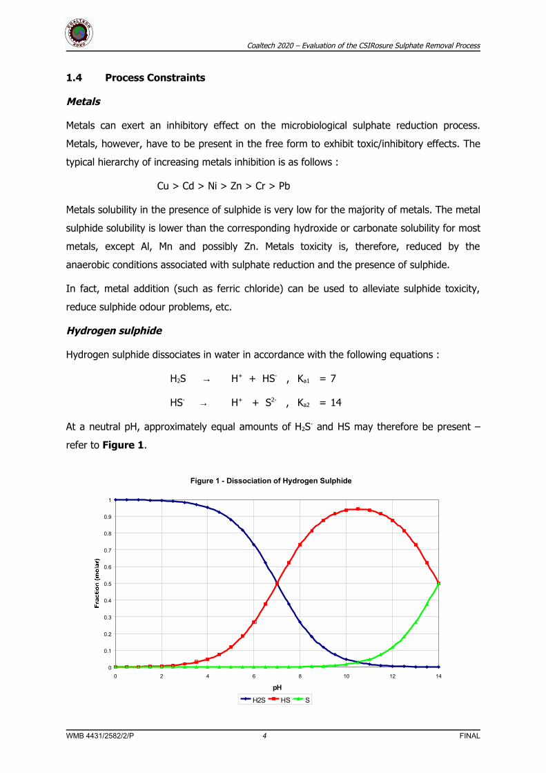
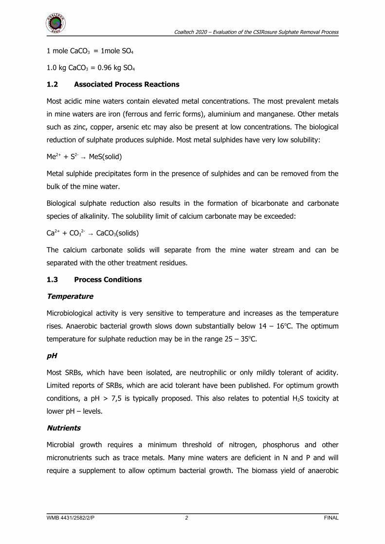
Figure 1 - Dissociation of Hydrogen Sulphide
0
0.1
0.2
0.3
0.4
0.5
0.6
0.7
0.8
0.9
1
0 2 4 6 8 10 12 14
pH
H2S HS S
Coaltech 2020 – Evaluation of the CSIRosure Sulphate Removal Process
1.4 Process Constraints
Metals
Metals can exert an inhibitory effect on the microbiological sulphate reduction process.
Metals, however, have to be present in the free form to exhibit toxic/inhibitory effects. The
typical hierarchy of increasing metals inhibition is as follows :
Cu > Cd > Ni > Zn > Cr > Pb
Metals solubility in the presence of sulphide is very low for the majority of metals. The metal
sulphide solubility is lower than the corresponding hydroxide or carbonate solubility for most
metals, except Al, Mn and possibly Zn. Metals toxicity is, therefore, reduced by the
anaerobic conditions associated with sulphate reduction and the presence of sulphide.
In fact, metal addition (such as ferric chloride) can be used to alleviate sulphide toxicity,
reduce sulphide odour problems, etc.
Hydrogen sulphide
Hydrogen sulphide dissociates in water in accordance with the following equations :
H2S → H+ + HS- , Ka1 = 7
HS- → H+ + S2- , Ka2 = 14
At a neutral pH, approximately equal amounts of H2S- and HS may therefore be present –
refer to Figure 1.
WMB 4431/2582/2/P 4 FINAL

Coaltech 2020 – Evaluation of the CSIRosure Sulphate Removal Process
The free aqueous H2S will also be in equilibrium with the gaseous H2S, in accordance with
Henry’s Law:
[H2S]aq = K [H2S]g
where:
[H2S]aq = hydrogen sulphide concentration in solution (mg/)
[H2S]g = hydrogen sulphide partial gas pressure (atm)
K = Henry’s Law constant
The inhibitory form of sulphide is assumed to be free H2S. The expression of inhibition and
toxicity is, however, not straightforward. Inhibition has been correlated with both free H2S
concentrations as well as with total sulphide concentrations. It has been postulated that
micro-organisms may have two inhibition thresholds, a lower one correlated with free H2S
and a higher one correlated with total sulphide.
Sulphide toxicity effects are further complicated by the difference in bacterial growth forms,
suspended growth or granular/pelletised growth. Diffusion gradients set up in
granular/pelletised sludge may be the reason for the lower observed toxicity, experienced in
granular and pelletised forms of sludges.
The Inhibition Concentration (IC) levels of free H2S, around a pH of 7,6 varies from
approximately 100 to 180 mg H2S/, depending on the specific substrate used by the SRBs.
2 CSIROSURE PROCESS EVALUATION
A demonstration plant for single stage biological sulphate removal was set up as part of the
Coaltech Initiative. The plant was designed with a nominal treatment capacity of 200 m3/day
to achieve at least 50% sulphate reduction, treating a neutralised mine water with a
sulphate concentration of 2200 – 2400 mg/.
The process evaluation was based on the operating and performance observations made at
the Coaltech Demonstration Plant located at Navigation Colliery, over the period
January 2000 to June 2001. Figure 2 shows a schematic process flow diagram of the
demonstration plant. Photograms 1 to 6 depict components of the Demonstration Plant.
WMB 4431/2582/2/P 5 FINAL
Coaltech 2020 – Evaluation of the CSIRosure Sulphate Removal Process
WMB 4431/2582/2/P 6 FINAL
Coaltech 2020 – Evaluation of the CSIRosure Sulphate Removal Process
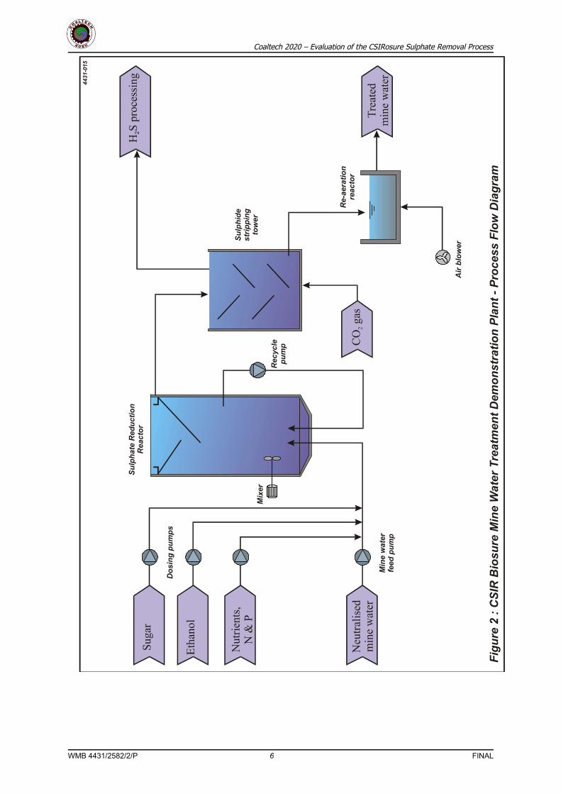
Photogram 1 : General Overview of the CSIR Demonstration Plant
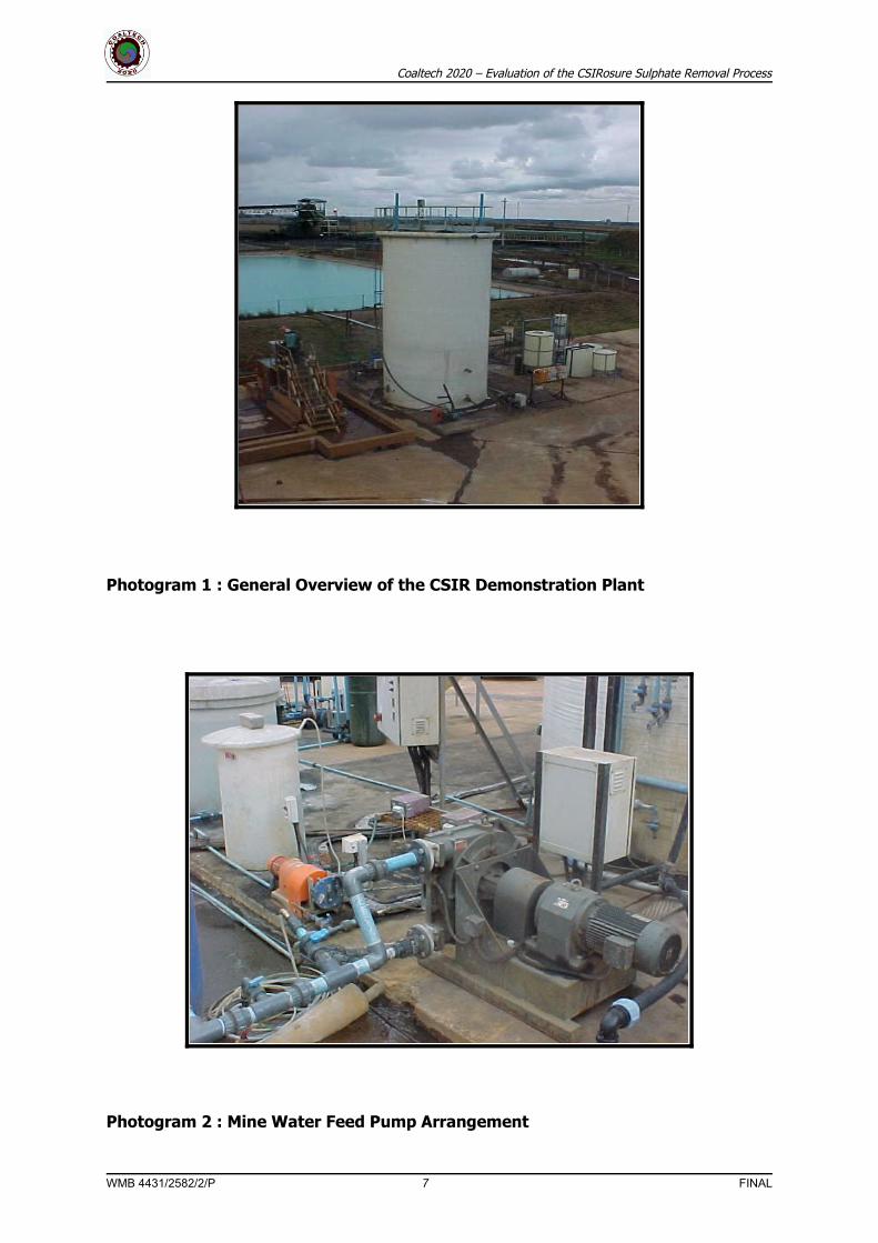
Photogram 2 : Mine Water Feed Pump Arrangement
WMB 4431/2582/2/P 7 FINAL
Coaltech 2020 – Evaluation of the CSIRosure Sulphate Removal Process
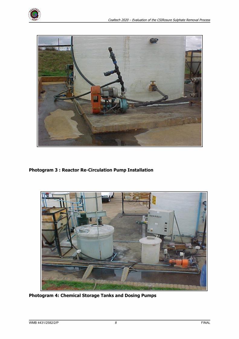
Photogram 3 : Reactor Re-Circulation Pump Installation
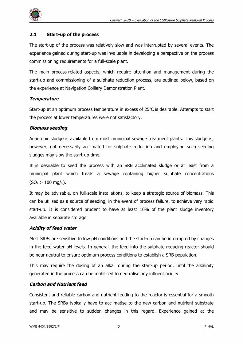
Photogram 4: Chemical Storage Tanks and Dosing Pumps
WMB 4431/2582/2/P 8 FINAL

Coaltech 2020 – Evaluation of the CSIRosure Sulphate Removal Process
Photogram 5: Central stilling well and mine water feed column
Photogram 6: Sulphate reduction reactor overflow
WMB 4431/2582/2/P 9 FINAL
Coaltech 2020 – Evaluation of the CSIRosure Sulphate Removal Process
2.1 Start-up of the process
The start-up of the process was relatively slow and was interrupted by several events. The
experience gained during start-up was invaluable in developing a perspective on the process
commissioning requirements for a full-scale plant.
The main process-related aspects, which require attention and management during the
start-up and commissioning of a sulphate reduction process, are outlined below, based on
the experience at Navigation Colliery Demonstration Plant.
Temperature
Start-up at an optimum process temperature in excess of 25oC is desirable. Attempts to start
the process at lower temperatures were not satisfactory.
Biomass seeding
Anaerobic sludge is available from most municipal sewage treatment plants. This sludge is,
however, not necessarily acclimated for sulphate reduction and employing such seeding
sludges may slow the start-up time.
It is desirable to seed the process with an SRB acclimated sludge or at least from a
municipal plant which treats a sewage containing higher sulphate concentrations
(SO4 > 100 mg/).
It may be advisable, on full-scale installations, to keep a strategic source of biomass. This
can be utilised as a source of seeding, in the event of process failure, to achieve very rapid
start-up. It is considered prudent to have at least 10% of the plant sludge inventory
available in separate storage.
Acidity of feed water
Most SRBs are sensitive to low pH conditions and the start-up can be interrupted by changes
in the feed water pH levels. In general, the feed into the sulphate-reducing reactor should
be near neutral to ensure optimum process conditions to establish a SRB population.
This may require the dosing of an alkali during the start-up period, until the alkalinity
generated in the process can be mobilised to neutralise any influent acidity.
Carbon and Nutrient feed
Consistent and reliable carbon and nutrient feeding to the reactor is essential for a smooth
start-up. The SRBs typically have to acclimatise to the new carbon and nutrient substrate
and may be sensitive to sudden changes in this regard. Experience gained at the
WMB 4431/2582/2/P 10 FINAL
Coaltech 2020 – Evaluation of the CSIRosure Sulphate Removal Process
Demonstration Plant indicated that virtually complete biomass loss from the reactor can
occur within 3 – 4 days, if the carbon / nutrient feed to the reactor is interrupted.
It is, therefore, essential to have redundancy and back up built into the carbon/ nutrient
storage and feeding facility to limit the risk of process failure.
Gypsum formation
During the initial start-up period, the reactor may still contain high sulphate levels, before
the reduction process becomes effective. If high calcium concentrations are also present,
which is typical for neutralised mine water, then gypsum crystallisation may take place
inside the reactor. Two negative effects may result :
• The bio-sludge would have a high inorganic content, which would modify the sludge density and
mixing/fluidisation characteristics.
• A reservoir of precipitated sulphate accumulates in the reactor, which first has to be removed
before the sulphate reduction efficiency of the reactor will increase to target levels.
The facility must be provided to waste excess sludge containing high gypsum levels from the
reactor, especially during start-up.
Oxygen ingress
The SRB population will be inhibited at even low levels of dissolved oxygen. Introduction of
air into the reactor under full-scale operational conditions, can easily take place (pump
suction, inlet turbulence etc.), if proper precautions are not taken.
An audit must be done during the plant start-up to identify and eliminate any sources of air
ingress into the reactor.
In general, it would appear that the sulphate reduction process can be commissioned to full
production levels within 2 – 3 weeks, provided that optimum process conditions can be
maintained.
2.2 Process Loading
The Biosure Demonstration Plant was operated at a steady flow and the following average
loading rates:
• Flow - 192 m3/day
• HRT - 10.3 hours
• SO4 loading rate - 5 – 6 kg SO4/m3/day
WMB 4431/2582/2/P 11 FINAL

Coaltech 2020 – Evaluation of the CSIRosure Sulphate Removal Process
This was achieved at a temperature in the range of 20 – 24 oC. Initial testing indicated that
at a higher reactor temperature of 30oC the following flow and loading rates may be
achievable:
• Flow - 400 m3/day
• HRT - 6 hours
• SO4 loading rate - 10 – 12 kg SO4/m3/day
2.3 Process conditions
2.3.1 Carbon Requirements
The Biosure Demonstration Plant was fed a carbon substrate consisting of:
• 200 mg/ sugar
• 720 mg/ ethanol B (75 % ethanol and 25 % propanol)
The equivalent COD was measured to be 1 750 mg/ (theoretical COD = 1 780 mg/). The
theoretical carbon requirements for sulphate removal is COD : SO4 = 0.67 on a mass basis.
Efficient SO4 removal of more than 75 – 85 % was achieved, when the carbon feed rate was
increased to a ratio of:
COD : SO4 = 0.9 –1 kg/kg
Virtually complete SO4 removal can be achieved by further increasing the carbon feed rate
to a ratio:
COD : SO4 > 1 – 1.2 kg/kg
The sugar carbon source is relatively expensive and this type of carbon source is probably
only required during start-up of the process. Sugar substrate produces high biomass
production compared to other carbon sources. This is beneficial during the initial start-up to
rapidly develop an adequate biomass inventory.
The effective carbon utilisation was estimated to be approximately 72 - 79 %. The
ineffective utilisation of carbon substrate could be associated with competing methanogenic
reactions (producing methane) or leakage of carbon substrate from the reactor. The latter
appears to be the case, since high acetate concentrations were recorded in the reactor
overflow.
WMB 4431/2582/2/P 12 FINAL

Coaltech 2020 – Evaluation of the CSIRosure Sulphate Removal Process
2.3.2 Nutrient Requirements
Macronutrients, N and P have to be supplemented to support the SRB biological population.
Typical nitrogen sources include urea, commercial fertilisers and various ammonium salts.
The most common phosphorus source is phosphoric acid. The N and P are typically dosed in
proportion to the feed COD (and therefore, indirectly to the feed SO4).
The Biosure Demonstration Plant was operated at the following nutrient supplement levels:
COD : N : P
= 1000 : 5.5 : 1.5
2.3.3 Alkalinity
The influent mine water was already neutralised, pH > 6.5, and no further alkali addition
was required. The Demonstration Plant achieved the anticipated alkalinity generation
(bicarbonate form), associated with sulphate reduction. The observed alkalinity production
was:
Alkalinity CaCO3 : SO4 reduced
= 1 : 1 on molar basis
= 1 : 0.96 on a mass basis
High alkalinity levels in the treated mine water, 1 500 – 2000 mg/ as CaCO3 should be
adequate to neutralise most acid mine waters, as an integral part of the sulphate removal
process.
2.3.4 Biomass Inventory
The biomass inventory progressively increased from 2 500 mg/ to 10 000 mg/ over a
three (3) month period. The biomass inventory stabilised at 10 000 mg/ over extended
period of operation. The sulphate removal capacity of the process also increased, since it
was demonstrated that the sulphate removal depends on biomass concentration. The
approximate dependency between sulphate reduction rate and biomass concentration can
be expressed as:
R = X0.85
Where R = sulphate reduction rate (kg SO4/m3/day)
X = biomass concentration (kg/m3)
WMB 4431/2582/2/P 13 FINAL

Coaltech 2020 – Evaluation of the CSIRosure Sulphate Removal Process
The biomass was fairly uniformly distributed in the mixed zone of the reactor. No biosolids
gradients were observed as one would expect in a upflow type reactor (UASB).
2.3.5 Sulphide Production
The sulphide production paced the sulphate reduction, except for a period of time when air
was fed into the top part of the reactor to enhance sulphur production.
The recorded concentration varied from 350 to 700 mg/ total sulphide, and no specific
adverse process response was detected. At a pH of 7.5, only 25 % of the total hydrogen
sulphide would be in the free un-dissociated form, corresponding to free H2S concentrations
of 87 – 175 mg/. This may be approaching the inhibitory levels reported in the literature.
2.3.6 Sulphide Stripping
The SRR effluent contained very high sulphide concentrations, typically in stochiometric
proportion to sulphate removed. The Demonstration Plant achieved very efficient sulphide
stripping in a two-stage reactor:
• Submerged packed reactor with a contact time of 20 mins.
• Trickling filter packed reactor with a contact time of 12 mins.
The sulphide was effectively stripped by CO2 gas, provided that the following molar ratio
was maintained:
CO2 : H2S > 5.9 mole/mole
2.4 Process Control
The Biosure Demonstration Plant did not incorporate any sophisticated control systems. The
process was manually controlled by:
• Selecting a hydraulic and sulphate loading rate and setting the appropriate mine water feed rate
• Setting the carbon feed and nutrient feed to pace the feed flow rate
• Monitoring the process performance and doing manual adjustments as necessary.
The lack of control over critical process parameters, such as temperature, created
difficulties, especially during the start-up phase of the project.
2.5 Process Performance
The Demonstration Plant achieved high levels of SO4 removal, after the process stabilised
and reliable carbon and nutrient feeds were established.
At COD : SO4 mass feed ratio’s around 0.8 – 1.0, approximately 75 –85 % SO4 removal was
achieved, resulting in residual SO4 concentrations of 400 – 700 mg/. When the COD : SO4
WMB 4431/2582/2/P 14 FINAL

Coaltech 2020 – Evaluation of the CSIRosure Sulphate Removal Process
mass feed ratio was increased to 1.1 –1.2, approximately 85 – 95 % sulphate removal was
achieved, giving residual SO4 concentrations of approximately 200 mg/.
The process did respond negatively to sudden changes in process and operating
parameters, such as:
• Interruptions to carbon/nutrient feed resulting in biomass washout.
• Drops in temperature
• Introduction of air/oxygen
The process is therefore sensitive to process changes, which result in loading and operating
conditions falling outside the stable optimum range for sulphate reduction.
The product water quality in terms of SO4 concentration did vary from day to day. This was
due primarily to fluctuations in the influent mine water SO4 concentrations. The
carbon/nutrient feed rate could not be exactly paced with the influent SO4load, due to the
absence of on-line sulphate concentration monitoring.
2.6 Residue Generation
The biological process generates an excess of bio-sludge. Anaerobic processes produce little
excess bio-sludge. The excess biomass production at the Demonstration Plant was
estimated to be:
0.02 kg VS/kg SO4 removed.
Calcium carbonate is also formed in the final aerobic polishing process step. Metal sulphides,
which precipitate in the SRR also contribute to the total waste sludge production.
2.7 By-products production
Hydrogen sulphide is the main process by-product. This is stripped into a CO2 gas stream for
further processing by either:
• Oxidation to sulphur; or
• Oxidation to sulphate
2.8 Safety and related aspects
The Biosure process employs potentially hazardous substances (such as phosphoric acid)
and flammable substances (such as ethanol). A potentially toxic gas, H2S, is also produced in
the process.
On the small scale of the Demo Plant, no specific automated warning systems were
implemented. Demonstration Plant operating personnel were alerted to the potential
WMB 4431/2582/2/P 15 FINAL
Coaltech 2020 – Evaluation of the CSIRosure Sulphate Removal Process
hazards and precautions were taken to prevent contact with hazardous and flammable
materials.
3 FULL-SCALE TREATMENT PLANT CONCEPTUAL DESIGN AND COSTING
The potential application of the treatment technology to a full-scale installation was
investigated, based on the interim results of the CSIRosure Demonstration Plant.
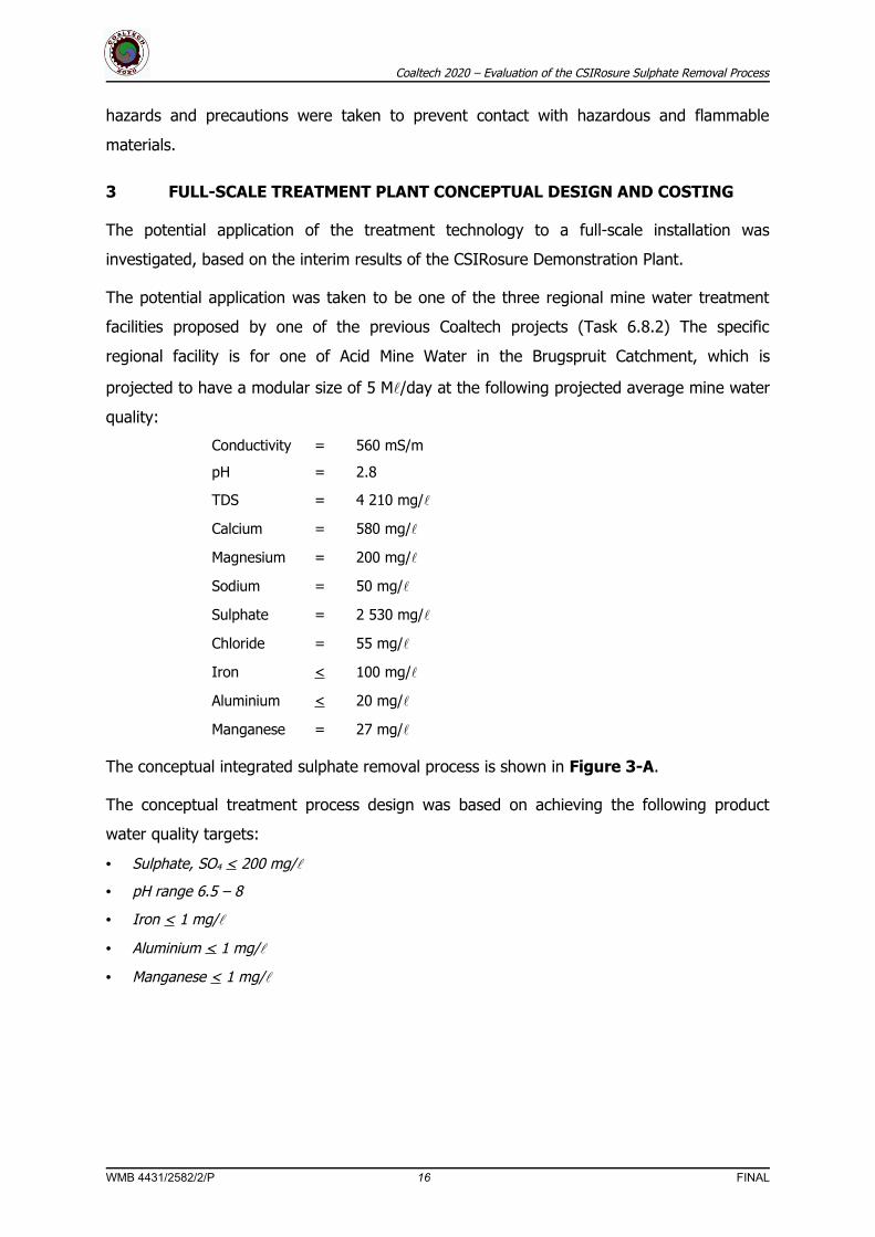
The potential application was taken to be one of the three regional mine water treatment
facilities proposed by one of the previous Coaltech projects (Task 6.8.2) The specific
regional facility is for one of Acid Mine Water in the Brugspruit Catchment, which is
projected to have a modular size of 5 M/day at the following projected average mine water
quality:
Conductivity = 560 mS/m
pH = 2.8
TDS = 4 210 mg/
Calcium = 580 mg/
Magnesium = 200 mg/
Sodium = 50 mg/
Sulphate = 2 530 mg/
Chloride = 55 mg/
Iron < 100 mg/
Aluminium < 20 mg/
Manganese = 27 mg/
The conceptual integrated sulphate removal process is shown in Figure 3-A.
The conceptual treatment process design was based on achieving the following product
water quality targets:
• Sulphate, SO4 < 200 mg/
• pH range 6.5 – 8
• Iron < 1 mg/
• Aluminium < 1 mg/
• Manganese < 1 mg/
WMB 4431/2582/2/P 16 FINAL

Coaltech 2020 – Evaluation of the CSIRosure Sulphate Removal Process
WMB 4431/2582/2/P 17 FINAL

Coaltech 2020 – Evaluation of the CSIRosure Sulphate Removal Process
3.1 Process Design Criteria
3.1.1 Temperature
The temperature will be controlled at 25oC – 30 oC for optimum biological sulphate. The mine
water heating requirements would be based on the following seasonal variation in
temperature:
Winter = 14oC
Summer = 23oC
3.1.2 Sulphate Reduction Reactors
The sulphate reduction reactor was based on the following hydraulic and sulphate loadings:
HRT = 8 hours
SO4 = 9 kg SO4/m3/day
3.1.3 Sulphide Scrubbers
The sulphate scrubber was designed for the following design loading rates:
• H2S volumetric loading = 54 kg H2S/m3/day
• Hydraulic loading = 26 m3/m2/hour
• Gas loading = 420 m3/m2/hour
3.1.4 Iron Oxidation Reactors
The sulphide spray tower was designed for the following loading rates:
• H2S volumetric loading = 32 kg H2S/m3/day
• Hydraulic loading = 1.3 m3/m2/hour
• Gas loading = 150 m3/m2/hour
3.1.5 Iron Oxidation Reactor
The iron oxidation reactor design was based on having pure oxygen available. The following
loading rates were used:
• Hydraulic retention time = 6 hours
• Iron oxidation rate = 1.5 kg Fe/m3/day
WMB 4431/2582/2/P 18 FINAL

Coaltech 2020 – Evaluation of the CSIRosure Sulphate Removal Process
3.1.6 Aerobic Polishing Reactors
The aerobic polishing reactor would be based on the step-feed activated sludge process,
using the following design criteria:
• Aerobic SRT = 4 days
• Maximum Biomass concentration = 2500 mg/
The bio-clarifier process design criteria would be as follows:
• Upflow rate = 0,8 m/hour
• Solids loading rate = 6 kg/m2/hour
3.1.7 Carbon storage and feeding
The conceptual design was based on the use of Ethanol B as carbon source with the
following design criteria:
• Storage capacity = 14 days
• COD : SO4 mass ratio = 1 kg/kg
3.2 Treatment Process Description
3.2.1 General Process Description
The proposed treatment involves sulphate reduction by anaerobic bacteria to sulphide in the
Sulphate Reduction Reactor (SRR) at 25 - 30 oC. The sulphide will then be stripped from the
water stream with a CO2 rich gas, generated during heating of the feed mine water. The
effluent from the stripping column will be aerobically polished to remove residual COD. In
the aerobic polishing reactor, CaCO3 will be precipitated that can be used as a neutralisation
agent.
Therefore, the following processes will take place on the main mine water stream:
• Heating of the feed water to 25 - 30 oC by combustion of coal
• Sulphate reduction in a Sulphate Reduction Reactor combined with integral settling tank
• Sulphide stripping with a carbon dioxide/nitrogen gas stream
• Aerobic polishing whereby residual solids/organics are removed from the water
On a side stream, three processes will be employed for the conversion of sulphide in the
stripping gas to sulphur. These three processes include:
• Sulphide rich gas contacted with an iron(III) solution to produce sulphur
WMB 4431/2582/2/P 19 FINAL
Coaltech 2020 – Evaluation of the CSIRosure Sulphate Removal Process
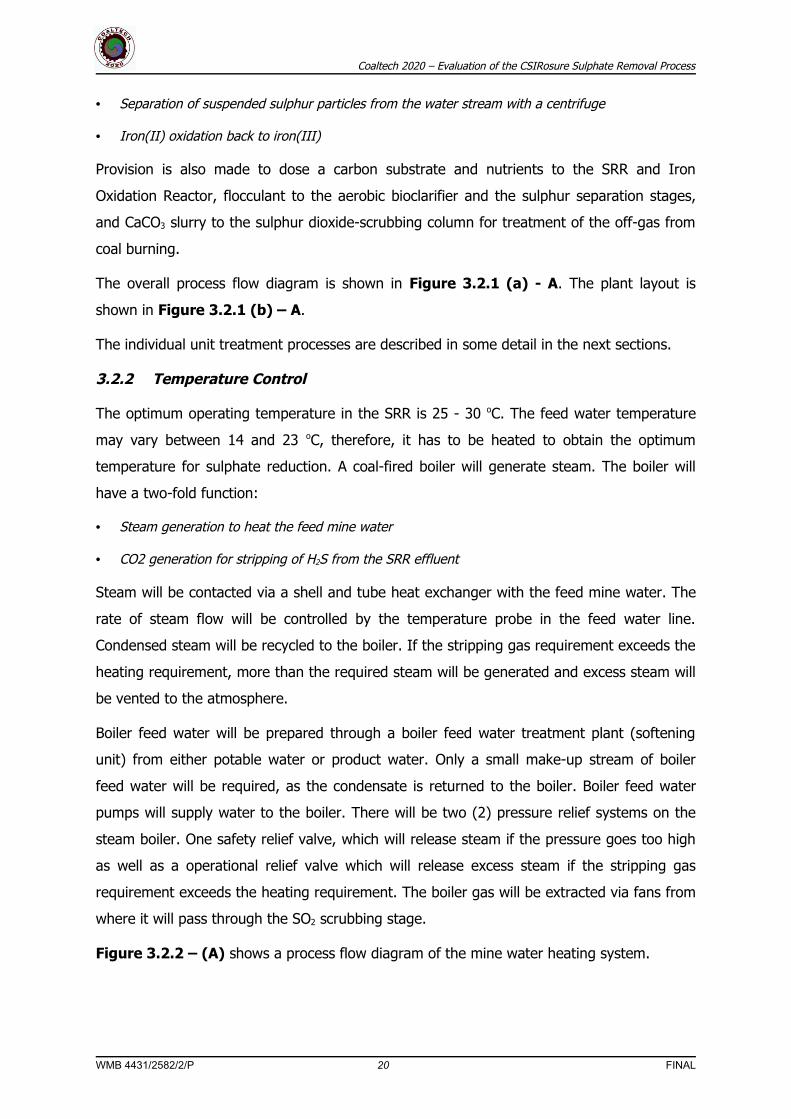
• Separation of suspended sulphur particles from the water stream with a centrifuge
• Iron(II) oxidation back to iron(III)
Provision is also made to dose a carbon substrate and nutrients to the SRR and Iron
Oxidation Reactor, flocculant to the aerobic bioclarifier and the sulphur separation stages,
and CaCO3 slurry to the sulphur dioxide-scrubbing column for treatment of the off-gas from
coal burning.
The overall process flow diagram is shown in Figure 3.2.1 (a) - A. The plant layout is
shown in Figure 3.2.1 (b) – A.
The individual unit treatment processes are described in some detail in the next sections.
3.2.2 Temperature Control
The optimum operating temperature in the SRR is 25 - 30 oC. The feed water temperature
may vary between 14 and 23 oC, therefore, it has to be heated to obtain the optimum
temperature for sulphate reduction. A coal-fired boiler will generate steam. The boiler will
have a two-fold function:
• Steam generation to heat the feed mine water
• CO2 generation for stripping of H2S from the SRR effluent
Steam will be contacted via a shell and tube heat exchanger with the feed mine water. The
rate of steam flow will be controlled by the temperature probe in the feed water line.
Condensed steam will be recycled to the boiler. If the stripping gas requirement exceeds the
heating requirement, more than the required steam will be generated and excess steam will
be vented to the atmosphere.
Boiler feed water will be prepared through a boiler feed water treatment plant (softening
unit) from either potable water or product water. Only a small make-up stream of boiler
feed water will be required, as the condensate is returned to the boiler. Boiler feed water
pumps will supply water to the boiler. There will be two (2) pressure relief systems on the
steam boiler. One safety relief valve, which will release steam if the pressure goes too high
as well as a operational relief valve which will release excess steam if the stripping gas
requirement exceeds the heating requirement. The boiler gas will be extracted via fans from
where it will pass through the SO2 scrubbing stage.
Figure 3.2.2 – (A) shows a process flow diagram of the mine water heating system.
WMB 4431/2582/2/P 20 FINAL

Coaltech 2020 – Evaluation of the CSIRosure Sulphate Removal Process
Figure 3.2.1 (a) - A
WMB 4431/2582/2/P 21 FINAL

Coaltech 2020 – Evaluation of the CSIRosure Sulphate Removal Process
Figure 3.2.1 (b) – A
WMB 4431/2582/2/P 22 FINAL

Coaltech 2020 – Evaluation of the CSIRosure Sulphate Removal Process
Figure 3.2.2 – (A)
WMB 4431/2582/2/P 23 FINAL

Coaltech 2020 – Evaluation of the CSIRosure Sulphate Removal Process
3.2.3 CO2 rich gas generation and scrubbing
The CO2 rich gas will be generated in the steam boiler. The gas will be treated in an SO2
scrubbing tower, while the excess is released to atmosphere. The stripping gas will be
contacted with limestone slurry in the SO2 scrubber. The limestone slurry will be stored in a
limestone day tank equipped with a mixer. Limestone slurry will be supplied from sludge
generated in the aerobic polishing reactor. The slurry will be dosed with a dosing pump into
the SO2 scrubbing tower together with make-up water from the product water line. The
scrubbing water will be recycled with the SO2 scrubber recycle pumps. The temperature in
the scrubbing tower will be high (>80 oC), depending on the gas temperature and flow. The
gas from the boiler will flow through the scrubbing tower and pass through a demister to
the H2S stripping column. A bleed stream will be taken from the scrubbing water circuit
through a manual control valve to the waste sludge sump.
3.2.4 Anaerobic Sulphate Reduction
In the anaerobic SRR , sulphate rich mine water is fed together with ethanol-b (a mixture of
ethanol - and propanol, sugar and nutrients. Provision is also made to inject steam into the
recycle line at a Venturi steam injector. The reactor is inoculated with anaerobic sewage
sludge and sulphate-reducing bacteria are selected through operating at the specific
environmental conditions. Sulphate is biologically reduced by the anaerobic oxidation of
ethanol in a complete mixed reactor or up-flow anaerobic sludge blanket (UASB) system.
The relevant chemical reaction for ethanol oxidation and sulphate reduction is:
3SO42- + 2CH3CH2OH → 3H2S + 6HCO3
-
The products of this reaction remain in solution and it is necessary to remove the residual
H2S and alkalinity. The net result is that sulphate is reduced to sulphide and that
bicarbonate is produced, which results in an increase in alkalinity.
The reactor can be operated either as an UASB reactor or as a complete mixed reactor. Two
sets of inlet nozzles to the reactor make provision for these two options. Recycle pumps will
mix the reactor. Sludge is retained by lamella settling plates positioned inside the reactor
and baffles will be placed underneath the lamella to prevent turbulence and sludge washout.
The overflow channels of the reactor will be capped to prevent H2S gas escaping to the
atmosphere. The SRR off gas will be abstracted with fans, from where it will go to the H2S
stripping tower.
WMB 4431/2582/2/P 24 FINAL

Coaltech 2020 – Evaluation of the CSIRosure Sulphate Removal Process
Waste anaerobic sludge can periodically be discharged to the waste sludge sump, where it
will be thickened and be available for re-use in the anaerobic reactor.
Figure 3.2.4 - A shows the process flow diagram of the sulphate reduction process.
3.2.5 Sulphide Stripping
The effluent from the SRR reactor is fed to a packed column, where it is contacted with a
CO2 rich gas stream. A counter-current flow configuration will be used. The CO2 dissolves in
the water and replaces the H2S in solution. H2S gas is thus transferred to the gas phase. The
following reaction takes place.
CaS(aq) + 2CO2(g) + 2H2O(aq) → Ca(HCO3)2(aq) + H2S(g)
The stripping columns will consist of tall packed (cross flow media) towers. A demister will
prevent the carry-over of aerosols into the gas flow. The released H2S is a gas and needs to
be precipitated in a solid form, because it cannot be vented to the atmosphere.
The water, from which the H2S stripped, is then further treated to remove residual COD and
to precipitate CaCO3.
3.2.6 Aerobic Polishing and Calcite Harvesting
The product from the H2S stripping column is fed to an aerobic reactor, which is aerated and
stirred mechanically.
Residual COD is degraded by aerobic bacteria and CO2 is produced. The calcium bicarbonate
is converted to calcium carbonate and precipitated, as follows:
2Ca(HCO3)2(aq) + O2(g) → 2CaCO3(s) + 2H2O(aq)
COD + O2(g) → CO2(g) + H2O(aq)
This will take place in the two aerobic reactor basins. Air will enter the bottom of the reactor
through a diffusion system. The solids will also be kept in suspension by mixers, positioned
on the aeration reactors.
The aeration basin overflows by gravity to the aerobic bioclarifier. The clarifier will be a
centre drive configuration. Sludge will either be recycled or pumped away for disposal.
The limestone sludge produced can be utilized as a neutralization agent.
Figure 3.2.6 – (A) shows a process flow diagram of the aerobic polishing process.
WMB 4431/2582/2/P 25 FINAL

Coaltech 2020 – Evaluation of the CSIRosure Sulphate Removal Process
Figure 3.2.4 - A
WMB 4431/2582/2/P 26 FINAL

Coaltech 2020 – Evaluation of the CSIRosure Sulphate Removal Process
Figure 3.2.6 – (A)
WMB 4431/2582/2/P 27 FINAL

Coaltech 2020 – Evaluation of the CSIRosure Sulphate Removal Process
3.2.7 Sulphide Oxidation
The sulphide rich gas stream is contacted with an iron(III) solution in a spray tower. The
recycle Fe III-rich stream, which is pumped from the recycle sump, will be divided into
several streams that are sprayed into the different column sections. The H2S gas will enter
the column from the bottom and flow through each column section, counter-current to the
water. H2S is absorbed into the water stream and reacts with the iron(III) according to the
following reaction:
3H2S(g) + 6Fe3+(aq) → 3S(s) + 6 Fe2+(aq) + 6H+(aq)
The gas stream exits the top column through a demister. Sulphur is produced as a
suspension in the iron(III) water stream. The water stream with the suspended sulphur exits
the column at the bottom and flows into the centrifuge feed sump – refer to
Figure 3.2.7 - A.
3.2.8 Sulphur Separation
Sulphur solids will be separated from the water stream by means of a centrifuge. Prior to
entering the centrifuge, the water is collected in the centrifuge feed sump. From the feed
sump, it is pumped by the centrifuge feed pumps to the centrifuge. The feed pumps will be
controlled by an input signal from a level sensor in the feed sump. There will be an overflow
from the centrifuge feed sump to the recycle sump. Prior to entering the centrifuge and the
centrifuge feed pumps, provision is made to dose a polymer to aid in coagulation of the
sulphur particles. In the centrifuge, the solid and liquid phases will be separated and a
sulphur cake will be produced – refer to Figure 3.2.7 - A.
3.2.9 Iron Oxidation
After the centrifuge, the water stream will enter the Iron Oxidation Reactor. Oxygen will be
blown into the reactor. The reactor will be packed with a plastic medium. The following
reaction catalysed by bacteria, will take place:
4Fe2+(aq) + O2(g) + 4H+(aq) → 4 Fe3+(aq) + 2H2O(aq)
WMB 4431/2582/2/P 28 FINAL

Coaltech 2020 – Evaluation of the CSIRosure Sulphate Removal Process
Figure 3.2.7 – (A)
WMB 4431/2582/2/P 29 FINAL

Coaltech 2020 – Evaluation of the CSIRosure Sulphate Removal Process
Provision will also be made to dose urea and phosphoric acid as nutrients for the bacterial
action. The water will overflow back into the recycle sump from whence it will be pumped
by the recycle pumps to the Sulphide Absorption Spray Columns. A level sensor in the sump
will protect the recycle pumps. There will be an overflow from the recycle sump to the
sludge sump. The sump will be kept full by means of a product water line and float valve.
The make-up ferrous sulphate will also be dosed directly into this sump – refer to
Figure 3.2.7 - A.
3.2.10 Chemicals Make-Up and Dosing
Chemicals that need to be dosed to the SRR include:
• Ethanol-b
• Sugar
• Phosphoric acid
• Urea
Chemicals to be dosed to the Iron Oxidation Reactor are:
• Ferrous sulphate
• Phosphoric acid
• Urea
• Oxygen
It will also be necessary to dose polymer to the sulphur separation and aerobic stages and
limestone slurry to the SO2 scrubbing tower.
The make-up and dosing facilities for each of these chemicals include the following:
• Ethanol-b
Delivered by tanker to bulk storage tanks and dosed with dosing pumps. Flow will be
measured with a rotameter. The Ethanol dosing will be interlocked with the mine water
pumps that will stop pumping, if ethanol dosing ceases.
• Sugar
Sugar will be delivered and stored in bags. It will be manually charged to the sugar make-up
tank where it will be dissolved in product water. The make-up tank will be equipped with a
mixer. There will be a strainer in the dosing line before the dosing pump from where the
sugar solution will go directly into the mine water feed line.
WMB 4431/2582/2/P 30 FINAL
Coaltech 2020 – Evaluation of the CSIRosure Sulphate Removal Process
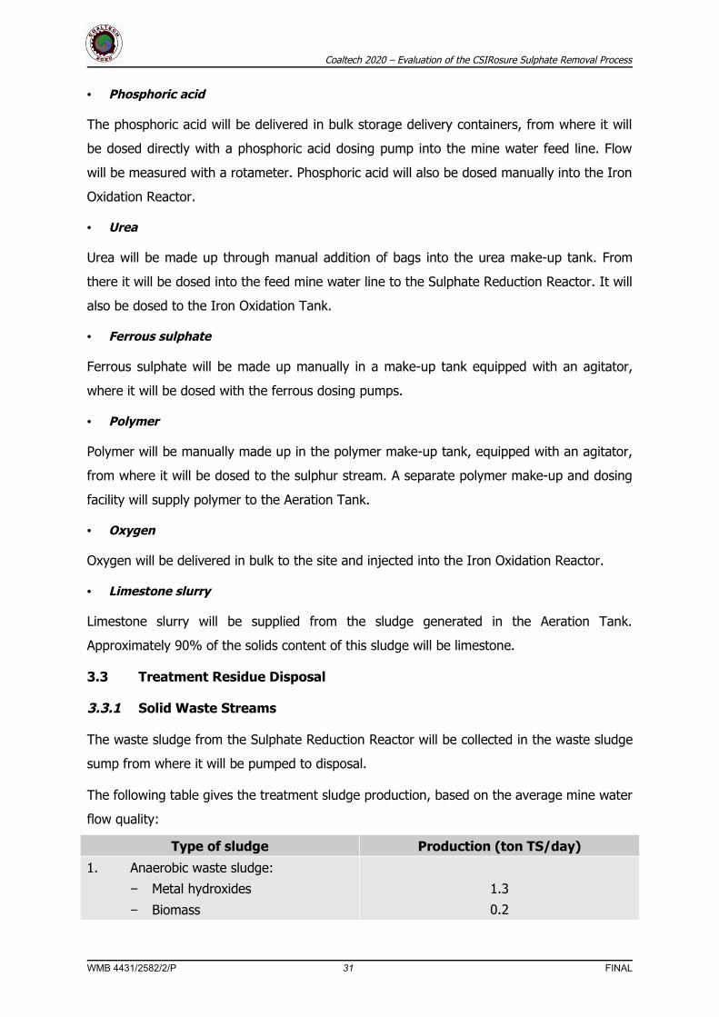
• Phosphoric acid
The phosphoric acid will be delivered in bulk storage delivery containers, from where it will
be dosed directly with a phosphoric acid dosing pump into the mine water feed line. Flow
will be measured with a rotameter. Phosphoric acid will also be dosed manually into the Iron
Oxidation Reactor.
• Urea
Urea will be made up through manual addition of bags into the urea make-up tank. From
there it will be dosed into the feed mine water line to the Sulphate Reduction Reactor. It will
also be dosed to the Iron Oxidation Tank.
• Ferrous sulphate
Ferrous sulphate will be made up manually in a make-up tank equipped with an agitator,
where it will be dosed with the ferrous dosing pumps.
• Polymer
Polymer will be manually made up in the polymer make-up tank, equipped with an agitator,
from where it will be dosed to the sulphur stream. A separate polymer make-up and dosing
facility will supply polymer to the Aeration Tank.
• Oxygen
Oxygen will be delivered in bulk to the site and injected into the Iron Oxidation Reactor.
• Limestone slurry
Limestone slurry will be supplied from the sludge generated in the Aeration Tank.
Approximately 90% of the solids content of this sludge will be limestone.
3.3 Treatment Residue Disposal
3.3.1 Solid Waste Streams
The waste sludge from the Sulphate Reduction Reactor will be collected in the waste sludge
sump from where it will be pumped to disposal.
The following table gives the treatment sludge production, based on the average mine water
flow quality:
Type of sludge Production (ton TS/day)
1. Anaerobic waste sludge:
− Metal hydroxides
− Biomass
1.3
0.2
WMB 4431/2582/2/P 31 FINAL

Coaltech 2020 – Evaluation of the CSIRosure Sulphate Removal Process
Type of sludge Production (ton TS/day)
2. Aerobic waste sludge:
− Limestone
− Biomass
6.5
0.8
3. Sulphur sludge 3.9
Total 12.7
The limestone sludge can be utilized in the further neutralisation of acid mine water
streams. The sulphur sludge will be co-disposed with the limestone sludge. The excess
alkalinity in the limestone sludge will prevent the onset of the acidic conditions required for
sulphur oxidation. The large mass of limestone sludge will also effectively encapsulate the
sulphur sludge, thus eliminating oxygen ingress and preventing sulphur oxidation.
3.3.2 Off-Gas Treatment
The off-gas from the Sulphate Reduction Reactor will be extracted with the fans and will be
discharged to the H2S Absorption Spray Tower.
The off gas from the H2S Absorption Spray Tower will be blown to a depth of 0.5 m below
the water surface into the Aeration Tank to capture and oxidise any fugitive H2S gas,
preventing its release to the atmosphere.
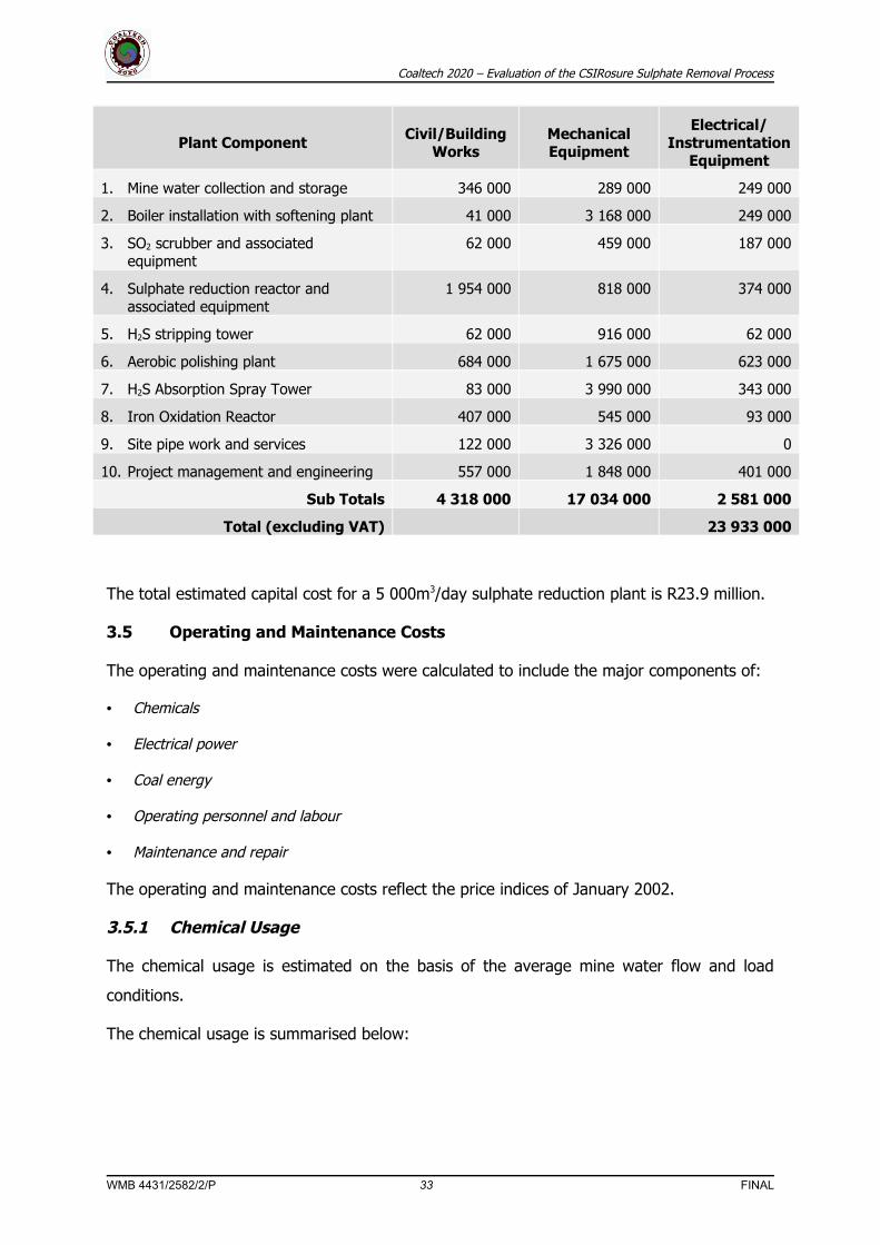
3.4 Capital Expenditure
The capital expenditure for the 5000 m3/day treatment module was estimated based on
January 2002 cost indices. The capital expenditure cost estimates was done at an indicative
level of accuracy (± 30 %). The capital investment for a specific plant site would be site
specific and would depend on the local situation related to:
• Local geotechnical and founding conditions
• Access to the site
• Provision of site services such as water, sanitation, electrical power and communications
• Infrastructure requirements to deliver the acid mine water to the treatment plant site in terms of
pumping, piping and storage
• Final disposal of the treatment plant residues and sludges
The capital cost estimates must therefore be considered in the light of the above
qualifications. The capital cost estimate is as follows:
WMB 4431/2582/2/P 32 FINAL
Coaltech 2020 – Evaluation of the CSIRosure Sulphate Removal Process
Plant Component Civil/Building Works
Mechanical Equipment
Electrical/ Instrumentation
Equipment
1. Mine water collection and storage 346 000 289 000 249 000
2. Boiler installation with softening plant 41 000 3 168 000 249 000
3. SO2 scrubber and associated equipment
62 000 459 000 187 000
4. Sulphate reduction reactor and associated equipment
1 954 000 818 000 374 000
5. H2S stripping tower 62 000 916 000 62 000
6. Aerobic polishing plant 684 000 1 675 000 623 000
7. H2S Absorption Spray Tower 83 000 3 990 000 343 000
8. Iron Oxidation Reactor 407 000 545 000 93 000
9. Site pipe work and services 122 000 3 326 000 0
10. Project management and engineering 557 000 1 848 000 401 000
Sub Totals 4 318 000 17 034 000 2 581 000
Total (excluding VAT) 23 933 000
The total estimated capital cost for a 5 000m3/day sulphate reduction plant is R23.9 million.
3.5 Operating and Maintenance Costs
The operating and maintenance costs were calculated to include the major components of:
• Chemicals
• Electrical power
• Coal energy
• Operating personnel and labour
• Maintenance and repair
The operating and maintenance costs reflect the price indices of January 2002.
3.5.1 Chemical Usage
The chemical usage is estimated on the basis of the average mine water flow and load
conditions.
The chemical usage is summarised below:
WMB 4431/2582/2/P 33 FINAL

Coaltech 2020 – Evaluation of the CSIRosure Sulphate Removal Process
Chemical type Consumption (kg/day as
pure)
Solution (%)
Unit cost (R/kg as chemical)
Daily cost
(R/day)
Ethanol 5 024 95 3.2 16 923
Sulphate reduction - urea 122 100 2.35 288
Sulphate reduction – phosphoric acid 49 85 4.5 260
Aerobic polishing – urea 78 100 2.35 184
Aerobic polishing– phosphoric acid 77 85 4.5 410
Aerobic polishing – polymer 5 100 35 175
Sulphide oxidation – ferrous sulphate 184 10 1.26 2 321
Sulphide oxidation – polymer 2 100 35 79
Sulphide oxidation – oxygen 2 157 100 0.65 1 402
Total 22 043
3.5.2 Electrical power
The installed power and the power drawn from each major individual mechanical equipment
item were estimated. The electrical power cost was estimated using a unit rate of :
R0.12 /kWhr
The estimated installed power and the daily energy cost are summarised below:
Equipment item Number installed
Installed power
kW/unit
Operating hours/day
Daily power cost
R/day
Feed water treatment plant 1 25 24 57.60
Boiler feed water pumps 2 17 12 39.17
Boiler 1 37 24 85.25
Off-gas fans 2 7.5 12 17.28
SO2 scrubber recycle pumps 2 11 12 25.34
Limestone agitator 1 1.5 24 3.46
SRR recycle pumps 3 11 8 25.34
Off-gas fans 2 2.2 12 5.07
Urea make-up tank mixer 1 1.1 4 0.42
Urea dosing pump 1 0.5 24 1.15
Phosphoric dosing pump 1 0.5 24 1.15
Ethanol dosing pump 1 0.5 24 1.15
Sugar make-up tank mixer 1 1.2 4 0.46
Sugar dosing pump 1 0.5 4 0.19
WMB 4431/2582/2/P 34 FINAL

Coaltech 2020 – Evaluation of the CSIRosure Sulphate Removal Process
Equipment item Number installed
Installed power
kW/unit
Operating hours/day
Daily power cost
R/day
Air blowers 2 110 12 253.44
Absorption gas blowers 1 11 24 25.34
Aeration tank mixers 2 22 24 101.38
Clarifier bridge drive 1 1.5 24 3.46
Sludge recycle pumps 2 11 12 25.34
Limestone sludge pumps 2 11 12 25.34
Centrifuge feed pumps 2 30 12 69.12
Centrifuge 1 55 24 126.72
Spray tower recycle pumps 2 17 12 39.17
Oxygen dissolution mixer 1 11 24 25.34
Waste sludge sump mixer 1 4.5 24 10.37
Waste sludge pumps 2 22 12 50.69
Total 1 018
3.5.3 Coal energy
The estimated coal consumption and cost are as follows:
• Coal usage = 5 ton/day
• Unit cost = R100/ton pebble coal
• Daily cost = R500/day
3.5.4 Operating personnel and labour
The cost associated with operating personnel and labour was based on a reasonable
assessment of the staffing requirements for a treatment plant. The proposed categories of
operating personnel and labour and associated monthly cost are summarised below:
Personnel Category Number Unit Cost (R/Month)Monthly Cost
(R/Month)Plant superintendent 1 9 000 9 000Process operators 4 6 500 26 000 Process assistants 2 4 500 9 000Labourers 5 2 000 10 000
Total cost 54 000
WMB 4431/2582/2/P 35 FINAL
Coaltech 2020 – Evaluation of the CSIRosure Sulphate Removal Process
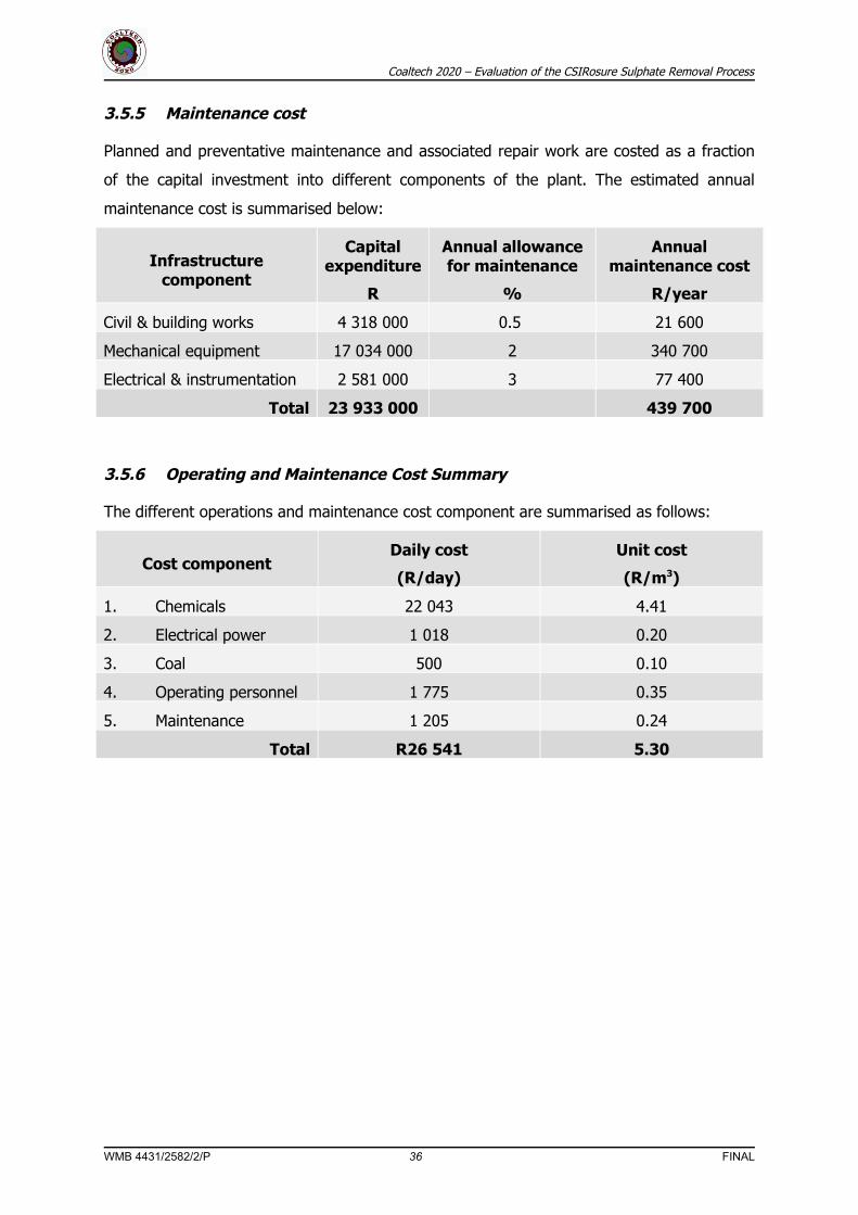
3.5.5 Maintenance cost
Planned and preventative maintenance and associated repair work are costed as a fraction
of the capital investment into different components of the plant. The estimated annual
maintenance cost is summarised below:
Infrastructure component
Capital expenditure
R
Annual allowance for maintenance
%
Annual maintenance cost
R/year
Civil & building works 4 318 000 0.5 21 600
Mechanical equipment 17 034 000 2 340 700
Electrical & instrumentation 2 581 000 3 77 400
Total 23 933 000 439 700
3.5.6 Operating and Maintenance Cost Summary
The different operations and maintenance cost component are summarised as follows:
Cost componentDaily cost
(R/day)
Unit cost
(R/m3)
1. Chemicals 22 043 4.41
2. Electrical power 1 018 0.20
3. Coal 500 0.10
4. Operating personnel 1 775 0.35
5. Maintenance 1 205 0.24
Total R26 541 5.30
WMB 4431/2582/2/P 36 FINAL