Coal Preparation, 1943 - Chapter 15 – Pneumatic Coal Cleaninglibrary.aimehq.org/library/books/Coal...
40
CHAPTER 15 PNEUMATIC COAL CLEANING BY E. C. CARRIB* T HE particular field of application of machines utilizing air cur- rents as the primary separating medium is in the cleaning of the fine sizes of bituminous coal. Approximately 18,000,000 tons of bituminous coal were cleaned by air machines during 1940.' They have not found any application for cleaning anthracite. Since the development and introduction of the first successful com- mercial pneumatic oscillating machine for cleaning bituminous coal in 1916, by the Sutton, Steele and Steele Co., Dallas, Texas, and the Ameri- can Coal Cleaning Corporation, formerly of Welch, W. Va., four other successful pneumatic coal-cleaning machines have been developed and introduced to the American coal-mining industry: 1. Peale Davis: "Pneumo-Gravity " machine, 1934. 2. Arms "Concentrator," oscillating table, 1934. 3. Hey1 and Patterson oscillating table, 1997. 4. "Stump Air-Flow," pulsating air jig, 1939. Out of these five developments only the Sutton, Steele and Steele, or American Oscillating, and the Stump Air-Flow Jig remain on the market. They are the predominating pneumatic coal-cleaning machines in use in the United States. HISTORY OF AMERICAN TYPE SEPARATOR The first successful American machine, the CJ table (Fig. 1) was developed by the Sutton, Steele and Steele Co. The SJ table was the first standard model designed specifically for the cleaning of coal. It was installed in the original Crane Creek plant, owned and operated by the American Coal Co. a t McComas, West Virginia. This plant was designed by The Roberts and Schaefer Co., Chicago, Ill., working in cooperation with the American Coal Cleaning Corpora- tion, which had taken over the patent rights and sale of the pneumatic separators. Eight machines were installed in this plant. They were known as the type SJ. They were 60 by 84 in., the short dimension being the width of * Director of Preparation, The Island Creek Coal Co., Holden. West Virginia. 1 Mechannwl (1941) 140. 494
Transcript of Coal Preparation, 1943 - Chapter 15 – Pneumatic Coal Cleaninglibrary.aimehq.org/library/books/Coal...

CHAPTER 15
PNEUMATIC COAL CLEANING
BY E. C. CARRIB*
T HE particular field of application of machines utilizing air cur- rents as the primary separating medium is in the cleaning of the fine sizes of bituminous coal. Approximately 18,000,000 tons of
bituminous coal were cleaned by air machines during 1940.' They have not found any application for cleaning anthracite.
Since the development and introduction of the first successful com- mercial pneumatic oscillating machine for cleaning bituminous coal in 1916, by the Sutton, Steele and Steele Co., Dallas, Texas, and the Ameri- can Coal Cleaning Corporation, formerly of Welch, W. Va., four other successful pneumatic coal-cleaning machines have been developed and introduced to the American coal-mining industry:
1. Peale Davis: "Pneumo-Gravity " machine, 1934. 2. Arms "Concentrator," oscillating table, 1934. 3. Hey1 and Patterson oscillating table, 1997. 4. "Stump Air-Flow," pulsating air jig, 1939. Out of these five developments only the Sutton, Steele and Steele, or
American Oscillating, and the Stump Air-Flow Jig remain on the market. They are the predominating pneumatic coal-cleaning machines in use in the United States.
HISTORY OF AMERICAN TYPE SEPARATOR
The first successful American machine, the CJ table (Fig. 1) was developed by the Sutton, Steele and Steele Co. The SJ table was the first standard model designed specifically for the cleaning of coal. I t was installed in the original Crane Creek plant, owned and operated by the American Coal Co. a t McComas, West Virginia.
This plant was designed by The Roberts and Schaefer Co., Chicago, Ill., working in cooperation with the American Coal Cleaning Corpora- tion, which had taken over the patent rights and sale of the pneumatic separators.
Eight machines were installed in this plant. They were known as the type SJ. They were 60 by 84 in., the short dimension being the width of
* Director of Preparation, The Island Creek Coal Co., Holden. West Virginia. 1 Mechannwl (1941) 140.
494

1 PNEUMATIC COAL CLEANING 495
the deck surface and the long dimension the length of the deck surface. The riffles paralleled the longer of the two dimensions as shown in Fig. 2.
The raw coal fed to these machines was very closely sized and dis- tributed in the following manner: 2 to 1-in., one separator; 1 to %-in., one separator; % t o %-in., two h d
separators; t o %-in., two sep- 4 arators; to %-in. two separa- tors; total, eight separators.
The minus >&in. coal was by-passed uncleaned, but in the latter part of 1924 i t became so contaminated with impurities that i t increased the ash content of the metallurgical slack to such a degree that i t was found nec- L------------ ,yean c&,f. - - - -. ~n?i.114&~q+~ essary to clean it. ' For this pur- Direction o f reci,broccat~on - Refup .
pose the American Coal Cleaning F1o. PLAN OF CJ TABLE (1916).
Corporation recommended the latest achievement of the Sutton, Steele and Steele Co., the "Wye" (Y) type sepa~ator (Fig. 3), especially designed for cleaning very fine coal, the contour of the deck of this machine being in the form of the letter Y, with the feed end a t the base
of the Y, which is approximately Feed the shape obtained if two S J tables
are joined. The original Wye-type sepa-
rator was installed on trial and operated on a commercial basis daily throughout the entire oper- ating shift. After three months of operation, during which many samples were taken, analyzed, and studied, it was found that by treating all the minus %-in. coal on five machines of this new t ~ ~ e
Direc fion ofreclprocofibn -+ i t would.reduce the ash of the slack FIG. %.-DECK PUN OF SJ TABLE (lQz@- and keep i t on the metallurgical
market. Therefore, during the latter part of 1925 and the early part of 1926, five Wye-type machines were installed to clean the minus %-in. coal. At the same time the first Menzie's Hydro Wet Washer was installed for cleaning the nut coal. This, probably, was the first combination wet and dry coal-cleaning plant. The stove and nut coal, plus %-in., were cleaned in water :machines and the minus %-in. coal in air machines.

496 COAL PREPARATION
Following the installation of the five uew Wye-type separators, the metallurgical slack market became more exacting and it became neces- sary to reduce the ash of the slack coal again. After several months of experimentation, trying various types of decking cloth, riffles, deck slopes, separator speeds, and toggle angularity, it was decided to recon-
1 Direction o f reciorocafion --+ I I I FIG. 3.-DECK PLAN OF WYE (Y) TABLE.
struct the entire deck of one separator to a full rectangular shape, with a warped surface, with all riffles installed diagonally to the direction of the separator motion, making an angle of la", with the spillage edge as shown on Fig. 4. The results from this type of deck were an immediate improvement over those of the Wye type. The remaining four separa- tors were equipped a t once with the new type of rectangular deck and
I I I
FIG. 4.-DECK PLAN OF RECTANGULAR TABLE.
satisfactory results were obtained for several months, when suddenly the slack market required a lower-ash coal. I n order to accomplish this, the old SJ separators, removed earlier when the stove and nut wet process was installed, were reconstructed into rectangular fine-coal machines and installed on the floor above the new fine-coal machines, so that the minus %-in. coal could receive a preliminary cleaning before being discharged to the machines on the lower floor. Though this idea proved expensive, the ash of the final clean coal was reduced another 0.5 per cent and was satisfactory for the market. Operations continued until some time in

1 PNEUMATIC COAL CLEANING 497
1929, when the plant caught fire and was completely destroyed. Follow- ing this, the American Coal Co. designed and constructed a new plant, incorporating ideas gained by experience in the operation of the old plant,
and including the use of water for cleaning the plus %-in. coal and air for the minus %-in. The dry part of this plant is shown on Fig. 5, designated as plant F.
The history of this plant was described a t some length for four reasons. 1. I t was the first pneumatic coal-cleaning plant of considerable size
in the United States. a. I t was in this plant that the first rectangular deck separator was
developed.

COAL PREPARATION
3. I t was probably the first combination wet and dry plant. 4. It was probably the first air plant t o utilize re-treatment. Upon the success of the rectangular deck, the American Coal Cleaning
Corporation made numerous installations, using the full rectangular deck on the cleaning of the finer sizes, while a half rectangular deck was designed for cleaning coarse coal up to 3-in. The half rectangular deck was used on the coarser coals because of the advantages obtained from transverse slope adjustment not employed in the full rectangular machine. The actual cleaning area of the original rectangular machine developed in the Crane Creek plant was 46 sq. ft.; the manufacturer later on designed and constructed some machines with three times that area.
-- D/recfion of rec/pmcaf/br, -+ I
PIG. PLAN OF TWIN-DECK TAULE.
During the latter part of 1939 and the early part of 1940, The Ameri- can Coal Cleaning Corporation and the Fairmont Machinery Co. designed and constructed what is known as the "Twin-Deck Separator," the deck plan of which is shown in Fig. 6. This machine comprises two single discharge decks with their spillage edges parallel and adjacent to each other, all mounted on a single running gear and actuated by a common variable-speed drive. The deck and supports are so mounted that, when oscillating, one deck counterbalances the other, minimizing vibration set up within the unit when operating a t maximum speeds. Both longi- tudinal and transverse slopes of the decks are adjustable independently of each other, while each deck has its own plenum chamber and supply fan. In other words, the decks are entirely independent of each other with the exception of the speed, and this is common to both decks.
While this machine is a new development, it is interesting to note that the manufacturer has returned t o the original shape of deck first intro- duced by the Sutton, Steele and Steele Co., the only difference being the increased length and direction of riffles. No data are available on the performance of this machine.
HISTORY OF STUMP AIR-FLOW MACHINE
The air-flow cleaner was developed by Earl Stump in 199% a t t h e testing plant of the Roberts and Schaefer Co., Harvey, Illinois.

PNEUMATIC COAI, CLEANING 499
The first commercial installation of this type of machine was a t a mine of the Barnes Coal Co., Barnesboro, Pa. This plant was designed and equipped with the type of machine shown in Fig. 7.
FIG. ~.- -~"IRsT COMMEACIAL AIR-FLOW MACHINE (1938).
This machine contained a dash pot actuating the refuse and middlings withdrawal lips, the movement being transmitted by means of the pulsat- ing air currents raising and lowering the float within the dash pot. There were no mechanical feeders on this machine; it received its coal supply by means of a gravity feeder attached to the bottom of the surge bin.
?
RQ. 8.-AIR-FLOW MACHINE (1933).
The marble pack and deck were made up loose and set in the machine. The pack consisted of a steel bottom plate with f / 4 to 1%-in. oblong per- forations, staggered arrangement, with an Armco-ste6l deck plate con- taining ?&-in. round perforations. in staggered arrangement.
The 1933 model (Fig. 8) contained a reciprocating feeder and glass side plates, exposing to view the bed stratification. The marble pack
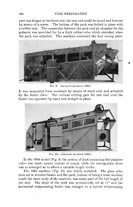
500 COAL PREPARATION
part was hinged a t the front end; the rear end could be raised and lowered by means of a screw. The bottom of the pack was bolted in place with a rubber seal. The connection between the pack and air chamber for the pulsator was provided for by a thick rubber tube, which stretched when the pack was adjusted. This machine contained the first zoning plate.
It was suspended from overhead by means of small rods and actuated by the feeder drive. The vertical cutting gate for raw coal over the feeder was operated by hand and wedged in place.
FIG. 10.-AIR-FLOW MACHINE (1935).
In the 1934 model (Fig. 9) the section of duct containing the pulsator valve was made square instead of round, while the zoning-plate drive was so arranged as to afford a variable .length stroke.
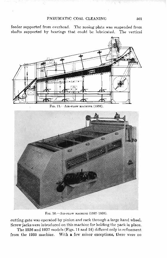
The 1935 machine (Fig. 10) was widely installed. The glass sides were set in wooden frames and the pack, instead of being a loose member inside the main body of the machine, was made part of the full length of the unit. The slope of the deck was permanently set a t 11° and the horizontal reciprocating feeder was changed to a curved reciprocating
PNEUMATIC COAL CLEANING 501
FIG. 1%-AIR-FLOW MACHINE (1997'1939).
cutting gate was operated by pinion and rack through a large hand wheel. Screw jacks were introduced on this machine for holding the pack in place.
The 1936 and 1937 models (Figs. 11 and 12) differed only in refinement from the 1935 machine. With a few minor exceptions, there were no

509 COAL PREPARATION
definite and major changes adopted until 1938 or 1939, when the width of the unit was increased from 3 ft. to 4 and 6 ft., while the dash-pot con- trol and its accessories were entirely removed and replaced by rotary valves, or star feeders containing six pockets. These valves are driven through a variable-speed transmission with a range of approximately 1 to 5. The zoning plate in this machine was changed from a punched- steel plate to a heavy and large-mesh wire cloth.
The 1941 model (Fig. 13) embodies the stage cleaning principle, or the multiple draw idea of removing the impurities as rapidly as they con-
FIG. 19.-AIR-FLOW MACHINE (1941).
centrate. So far, this machine contains a primary and secondary refuse draw, plus a combined middlings and refuse draw a t the discharge end of the machine. The rotary draws have been replaced by a reciprocating pusher-type gate, all gates being driven by a single constant-speed crank. The variation of material removed is attained by means of adjustable hand screws, which increase or decrease the length of stroke of the pusher gate. Likewise, the reciprocating curve feeder has been replaced by a pusher-type reciprocating feeder, driven by means of a crank through a variable-speed transmission. The refuse material from the primary and secondary draws is discharged into separate worm conveyors, which carry the material to the outside of the machine where i t can be sampled and readily inspected by the operator a t all times.
The wedge-shaped marble pack has also been replaced by a uniform depth pack the full length of the cleaning surface. The air beneath the

PNEUMATIC COAL CLEANING
pack and bed is controlled over the entire length and breadth of the machine, by means of perforated sliding plates operrtted from the exterior of the machine. By means of these plates, the open area may be increased and decreased a t will every 6 in. of length throughout the full length of the cleaning surface.
PRINCIPLE OF AMERICAN OSCILLATING SEPARATOR
When a stream of coal is discharged upon the deck surface of an air table it moves parallel to the axis under the influence of the oscillating motion and the pushing effect of the material behind it. The recipro- cating motion of the deck exerts a force on the particles, the extent and direction of which is determined by three adjustments: length of stroke, number of strokes per minute, and toggle angle. The effect of the applied force is to throw the particles forward and slightly upward, out of contact with the deck surface, to which they rapidly settle during the backward stroke. In settling they are opposed by the force of the upward air currents.
Of particles of the same size and specific gravities, the heavier settle the more rapidly. After a few repetitions of the oscillating cycle the lowest layer of the bed is composed mostly of coarse impurities; above this stratum a layer of intermediate material, and above this a layer of coarse coal. If the volume and velocity of the upward air currents are sufficient, the fine coal particles will be unable to penetrate the bed of coarse particles to any appreciable degree and will form a layer on top. The fine particles of impurities and intermediate particles will settle down through the coarse coal layer and to some extent into the coarse impurity layer.
When stratification is complete, the raw coal will have moved a short distance away from the feed end of the deck and be subject to the forces that determine the position of discharge along the spillage edge of the deck; these forces being the propelling motion of the deck, the transverse and longitudinal slope of the deck, and the support of the riffles and tailing riffle that is the spillage edge, and to some extent the upward air currents.
If the air supply and deck motion are properly adjusted to effect correct stratification, the bed is sufficiently fluid to flow readily downward across the transverse slope. The transverse flow of the lower layer or heavy particles is prevented by the riffles so that it is forced to move along a path parallel to the axis of the deck when the riffles are parallel to the motion and a t a slight diagonal when the riffles protrude from the spillage edge to the center of the deck. If the motion of the deck is sufficient to force the bed up the longitudinal slope of the deck, the upper layer, not being constrained by the riffles, takes a diagonal path that is the result of the motion of the deck, transverse and longitudinal slopes, plus the magnitude of the upward air currents. As the heavier material

504 COAL PREPARATION
behind the riffles moves forward, the vertical taper of the riffles removes the transverse support from the various layers of material and these in turn follow their respective paths to the discharge edge and are segregated into three products-clean coal, middlings, and refuse.
AMERICSN OSCILLATING TABLE
'l'here are five major adjustments to the oscillating type of machine: (1) air supply, (2) speed and length of stroke, (3) toggle angularity, (4) longitudinal slope of deck surface, and (5) transverse slope of deck surface.
Air supply and distribution are the most important of all the adjust- ments and should be readily accessible to the operator and accurately controllable by him. The ideal quantity of air is that which rising upward through the bed offers sufficient resistance to the fall of particles to produce stratification and settling of the different particles according to the laws governing the settlement of solids in fluids. Fine coal and fine impurities tend to settle through the voids made by the coarse particles after the bed has come to rest. The upward air currents must be sufficient to prevent the settling of fine coal, but the fine impurities should settle below the coarse coal, so that after the respective layers of material are sheared off by gravity as their support is removed because of the tapering riffles, the order of discharges over the spillage edge should be fine coal, coarse coal, middlings and refuse.
It is common practice among table operators to use excessive air currents to try to create such a condition, when a slight increase in speed and toggle angle will accomplish the same result without detriment to the performance.
Proper adjustment of air currents, coordinated with adjustment of speed and toggle angle, affects the stratification and mobility of the bed; the transverse slope adjustment has no definite effect upon stratification but 'the longitudinal slope and transverse slope are instruments for effecting the discharge of the various products a t the desired place along the spillage edge. Thus the proper order of adjustments is to effect a balance between air, speed, and toggle angle. These three adjustments properly coordinated will cause good stratification and mobility. A steep toggle angle and increased speed with reduced air will sometimes accomplish the same result with greater efficiency and economy than stratifying and discharge of the various products along the spillage edge by means of longitudinal and transverse slopes plus excessive air.
Operation and Maintenance
The American oscillating tyble must be operated with a definite and uniform feed in order to maintain a uniform stratified bed. No mechani- cal regulation has ever been devised for this machine. It must receive constant attention, and the products discharging from it must be in full

PNEUMATIC COAL CLEANING 5 05
view of the attendant a t all times. When a surge of increased sink material discharges upon the separator, the cutting finger removing the refuse must be shifted. It will not move itself; neither will i t shift when the sink material is a t a minimum. I t is quite unusual to find a coal that does not fluctuate to some extent in percentages of impurities and extraneous moisture. These fluctuations can be controlled only by constant attention to the machine. If these fluctuations are neglected, the uniformity of the final clean ~ r o d u c t will be considerably impaired a t the expense of coal lost in the refuse.
Air controls must be readily accessible to the operator, so that the amount of air may be quick& increased when wet coal discharges upon the deck. This procedure is necessary not only to obtain some cleaning of the coal, but to prevent the perforations in the decking cloth from becoming excessively blind. If the surge of wet coal lasts for any appreciable length of time, and the air is not increased immediately, the decking will blind so badly that it will not respond and open up even after dry coal returns. It is essential, particularly where coal below x-in. is being cleaned, to check for wet coal very closely. It is advisable to have a quick-acting cut-off gate, so that if the deck does become blind the feed may be stopped momentarily and the decking hurriedly cleaned.
A very good method of cleaning the decking cloth is to clear the bed of coal off the separator and then tap the top of the riffles with a small piece of 2 by 4 while having the air on full force. This is more effective if the decking cloth has been dried.
The separator should be checked frequently for loose deck bolts. Where pin and toggles are employed, the bushings must not be allowed to become badly worn, for if they are worn excessive lost motion will disturb the rigidity of the deck, creating a retarding effect upon the movement of the impurities along the surface. The stratification and mobility of the bed depend upon a definite and positive oscillating move- ment. If this movement is affected by poor foundations, loose deck bolts, or worn toggle bushings, the over-all performance is impaired.
It is always advisable to establish a systematic method for cleaning the deck and checking over the entire machine. The deck should be thoroughly cleaned a t least twice a week, and more frequently if surface moisture, fine impurities, and shooting wire tend to blind it. The deck should never be left standing over night with a bed of wet coal upon it. If the operating shift ends with a run of wet coal, always clear the bin and the deck, so that during the night the deck cloth will dry out and thus permit easier cleaning of the cloth before starting the morning shift.
When a number of separators are used, the tonnage should be equally divided among them. For example, if the plant is composed of four machines, divide the tonnage in such a way that each of them will have the same load.

506 COAL PREPARATION
Size
TABLE 1.-Average Yearly Perjormances
- --
Size, Per Sink, Per Size Per Sink. Per 1 c e n t 1 c e n t ~ l n t 1 c e n t I percent
Raw Coal Clean Coal
3 ~ 6 " t ~ 1 4 m . . . . . . . . . . . . . . . . . . . . 1 4 m . t o 4 8 m . . . . . . . . . . . . . . . . . . . -48 m . . . . . . . . . . . . . . . . . . . . . . . . .
FINAL REFUSE COMPOBITE OF 1937-1938
71.38 20.20 8.42
9.50 11.32
Size
4{8'1 to 6 m. . . . . . . . . . . . . . . . . . . . . . . . . . . . . . . . . . . . . . . . . . . . . . . . 6 m.to 14 m... . . . . . . . . . . . . . . . . . . . . . . . . . . . . . . . . . . . . . . . . . . . . 1 4 m . t o 4 8 m . . . . . . . . . . . . . . . . . . . . . . . . . . . . . . . . . . . . . . . . . . . . . . -48m . . . . . . . . . . . . . . . . . . . . . . . . . . . . . . . . . . . . . . . . . . . . . . . . . . . . Composite . . . . . . . . . . . . . . . . . . . . . . . . . . . . . . . . . . . . . . . . . . . . . . . . .
Size, Per Cent
65.07 29.86 4.84 0.W
100.00
Material
Raw coal. . . . . . . . . .
Clean coal.. . . . . . . .
-
67.9 25.7
70.54 Q4.83 4.63
Float, Per Cent
e0.S 19.08 7.00 0.00
19.20
Sink, Per Cent
8.05 8.52 9.02 9.25
11.59
8.68 1.72 2.21 9.74 4.97 8.76
3.04
4.00 8.33
Size
446'' to ?-it'
34'' to 6 m. 6 m. to 10 m.
10 m. to 14 m. 14 m. to 48 m. -48 m. Composite x6" to 14 m. x6" to f/4"
to 6 m. 6 m. to 10 m.
10 m. to 14 m. 14 m. to 48 m. -48 m. Composite xa" to 14 m.
ReEkyB1, Per Cent
78.60 74.90 68.50 46.90 34.40
64.7
Size, Per Cent
10.42 26.04 19.10 8.10
25.35 10.99
6.00 32.00 21.60 10.00 23.60 8.00
Cumulative, Per Cent
10.42 96.46 55.66 69.66 89.01
100.00
6.00 38.00 58.60 69.60 92.00
100.00

PNEUMATIC COAL CLEANING
TABLE 1 .-(Continued)
Testing specific gravity.. . . . . . . . . . . . . . . . . . . . . . . . . . . . . . . . . Capacity, tons per hr . . . . . . . . . . . . . . . . . . . . . . . . . . . . . . . . . . . . Separator capacity, tons per hr. . . . . . . . . . .
Material
Refuse. . . . . . . . . . .
Actual capacity per sq. ft. deck surface, tons per hr . . . . . . . . . . . . . . . . Middlings recirculated to raw feed coal Static pressure below bed, inches water.. . . . . . . . . . . . . . . . . . . . . . . . . . Suction above bed a t apex of hood, inches water.. . . . . . . . . . . . . . . . . .
. . . . . Volume of supply air, cu. ft. per min. per sq, ft. deck surface.. Volume of exhaust air, cu. ft. per min. . . . . . . . . . . . . . . . . . . . . . . . . . . .
. . . . . . . . . . . . . . . . . . . . . . . . . . . . . . . . . . . . . Speed of separators, 1.p.m.. Volume of air to deduster, cu. ft. per min.. . . . . . . . . . . . . . . . . . . . . . . . Toggle setting: 55O with horizontal Total length of stroke, in.. . . . . . . . . . . . . . . . . . . . . . . . . . . . . . . . . . . . . . . Longitudinal slope deck surface, in. per ft.. . . . . . . . . . . . . . . . . . . . . . . Lateral slope across feed end from center, in. per ft . . . . . . . . . . . . . . . . . Lateral slope from apex of banking bar, in. per f t . . . . . . . . . . . . . . . . . .
DECKING SPECIFICATIONS: a. Manganese bronze m'etal strips with x6-in. risers b. 0.098-in. diameter perforations
Float. Per Cent
e6.64 18.%1 16.71 , 6.84 4.93 0.00
18.115
c. 220 boles per sq. in., staggered arrangement
--
d. 24 gauge RIFFLE SPECIFICATIONS:
a. Height of butt end, in . . . . . . . . . . . . . . . . . . . . . . . . . . . . . . . . . . b. Height of tip end, in.. . . . . . . . . . . . . . . . . . . . . . . . . . . . . . . . . . c. Height of tail riffles butt end, in.. . . . . . . . . . . . . . . . . . . . . . . . d. Height of tail riffles tip end, in.. . . . . . . . . . . . . . . . . . . . . . . . . . e. All deck riffles taper, with tailing riffles along spillage edge f. Total connected load, %47 horsepower
PLANT COSTS (BAEED ON 500,000 TONE CLEAN COAL)
Cumulative Per Cent
13.15 62.90 86.65 94.30 99.4%
100.0
Size
x6" to XIr j/4" to 6 m. 6 m. to 10 m. 10 m. to 14 m. 14 m. to 48 m. -48 in. Composite x6" to 14 m.
Operating and supplies.. . . . . . . . . . . . . . . . . . . . . . . . . . . . . . . . . . . . . . . . . . . . . . . . . . . . . . . . . . . . . . . . . . . . . . . . . . . . . . . Maintenance and supplies.
Refuse disposal.. . . . . . . . . . . . . . . . . . . . . . . . . . . . . . . . . . . . . . . . . . . . . . . . Powera. . . . . . . . . . . . . . . . . . . . . . . . . . . . . . . . . . . . . . . . . . . . . . . . . . . . . . . .
Size, Per Cent
13.15 49.75 9.3.75 7.65 5.1% 0.58
Total. . . . . . . . . . . . . . . . . . . . . . . . . . . . . . . . . . . . . . . . . . . . . . . . . .

5 08 COAL PREPARATION
Inasmuch as the adjustments are so vitally important to efficient performance, it is advisable to check them occasionally, because no matter how securely they are made and guarded they will change.
Performance
Plant h (Fig. 14) is composed of six rectangular separators, type 60 by 120 in. with 10-ton cylinder surge bins ahead of each unit, adjustable
gravity feeders anti quick-acting cutoff gates. Each separator receives its feed coal from a centrally slotted feed pan, which is secured to the deck ant1 oscillates with it. This method of feed prevents any abnormal piling of the coal upon the rear of the deck, thereby affording quicker
PNEUMATIC COAL CLEANING 509
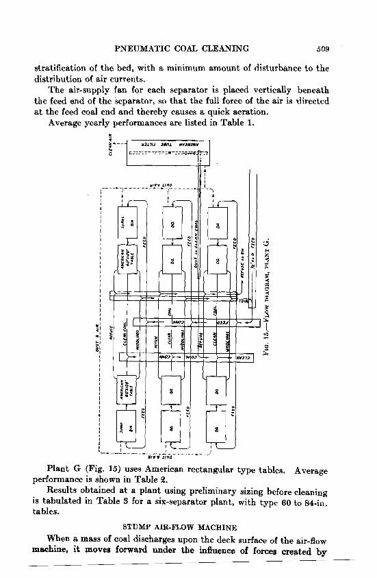
stratification of the bed, with a minimum amount of disturbance to the distribution of air currents.
The air-supply fan for each separator is placed vertically beneath the feed end of the separator, so that the full force of the air is directed a t the feed coal end and thereby causes a quick aeration.
Average yearly performances are listed in Table 1.
Plant G (Fig. 15) uses American rectangular type tables. Average performance is shown in Table 2.
Results obtained a t a plant using preliminary sizing before cleaning is tabulated in Table 3 for a six-separator plant, with type 60 to 84-in. tables.
STUMP AIR-FLOW MACHINE
When a mass of coal discharges upon the deck surface of the air-flow machine, it moves forward under the influence of forces created by
COAL PREPARATION
longitudinal downward slope, pulsating air currents, zoning plate move- ment and the crowding of incoming material from the feeder. Stratifica- tion is somewhat similar to that effected on the oscillating machine, the lower layer next to the deck surface being composed mainly of coarse, heavy impurities while directly above and next to this is a stratum of intermediate material, followed by a layer of coarse coal and on top of this the fine coal.
Air-$ow Adjustments
As in the oscillating machine, air supply is the most important adjust- ment. It should be readily and easily controlled for variations in surface moisture of the feed coal.
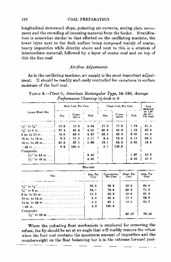
TABLE %.-Plant G, American Rectangular Type, 54-140, Average Performan,ce Clean,in,g %-inch to 0
i Raw Coal, Per Cent
Square Mesh Size 1 1 Size 7:~-
Sink Removal at 1.80
Per Sp. Cent Gr.,
Clean Coal, Per Cent
Snk
____
61.5 60.8 54.3 38.0 16.5
55.3 47.3
Size
. . . . . . . MI' t o M f 1 . , I 15.8 I/qf' to 6 m . . . . . . . . . . ( '27.4 6 m . t o 1 0 m . . . . . . . . 18.8 1 0 m . t o 1 4 m . . . . . . . 9 . 3 1 4 m . t o 4 8 m . . . . . . . 21.8 -48 m . . . . . . . . . . . . . . 6.9
c""- lative ___
17.0 43.9 66.4 75 .8 94.9
100.0
REFUSE
Sink
___
1.74 1 .59 2.05 3.17 4.95
1.97 e.56
Composite %"to 14 m . . . . . %"to 48 m . . . . .
15.8 43.3
4.53 4.05
Where the pulsating float mechanism is employed for removing the refuse, the lip should be set a t an angle that will readily remove the refuse when the feed coal contains the maximum amount of impurities and the counterweight on the float balancing bar is in the extreme forward posi-
Float, Per Cent
33.0 29. o 18.6 17.E 15 .3
36.57
Cumulative. Per Cent
38.8 73.9 88. % 91.8 97.1
100.0
Size / Size, Per 1 Cent
17.0 36.9
63.0 4.47 5 .11 ii:; 1 5 . 9 3
100.0
Sink. Per Cent
68.0 71.0 81.4 83.8 84.7
73.43
-- -
$6" t o f / 4 " . . . . . . . . . . . . . . . . . . . . . . . . . . . . xi' t o 6 m . . . . . . . . . . . . . . . . . . . . . . . . . . . . 6 m . t o 1 0 m . . . . . . . . . . . . . . . . . . . . . . . . . . l o r n , t o 1 4 m . . . . . . . . . . . . . . . . . . . . . . . . . 1 4 m . t o 4 8 m . . . . . . . . . . . . . . . . . . . . . . . . .
. . . . . . . . . . . . . . . . . . . . . . . . . . . . . . -48m Composite
t o 48 m . . . . . . . . . . . . . . . . . . . . . . .
33 .5 9 .4
19.1 5 . 1
--
38.8 34.1 15.3 3 .6 5 . 3 '2.9

PNEUMATIC COAL CLEANING 511
tion. With this setting, variations in percentages of impurities can be readily taken care of by controlling the position of counterweight on the bar. The balancing bar should be long enough for a wide range of positions.
TABLE 3.-Size and Speci$c-gravity Perjormance of a Six-separator Plant Employing Single Side-disch.arge Oscillating Separators, Type 60 to
84 Inches, Preliminary Sizing befme Cleaning
Material
Raw coal
$6" to 9 $ z ' r . . . . . . . . . . .
Composite. . . . . . . . . . . .
Size
g " to 6 m. 6 m. to 14 m. 14 m, to 48 m. -48 m. g" to 14 m. f/4" to 48 m.
Size, Per Cent
44.5 45.1
6 . 6 3 . 8
89.6 96.2
Sink, Per Cent
Sink Removal, Per Cent
Clean coal g" to Xi1 ' . . . . . . . . . . . . .
Composite.. . . . . . . . . . . . . . .
Raw coal %2" to 0 .
Composite. . . . . . . . . . . . . . . . . . . . . . . .
Clean coal X2" to 0 . . . . . . . . . . . . . . . . . . . . . . . . .
Composite. . . . . . . . . . . . . . . . . . . . . . . .
Composite Refuse 1 Size / Size. Per 1 Float, Per Cent Cent
. . . . . . . . . . . . . . . . . . . . . . . . . . . . . . . . . . . . . %'' to0 X 1 ' t o 6 m . 77.6 1 -6 m. 1 22.4 Composite.. . . . . . . . . . . . . . . . . . . . . . . . . . . . . . . . . . xu to 0 100.0
The zoning plate, while not considered as an adjustment of the unit, does play an importantpart in the mobility of the bed. The height above the deck surface depends upon the depth of bed and the thickness of refuse layer. With a bed of approximately 5 in. a t the discharge end of the machine, it has been found that this plate is most effective a t a height of 146 to 2 in. above the deck surface and protruding slightly into the refuse layer. The kize of perforations varies a t various installations

5 18 COAL PREPARATION
from 3 in. square to 1 in. square. The size of opening depends somewhat upon the surface moisture and size of the feed coal. A heavy steel plate with 1%-in. square-mesh perforations gives good results under most conditions of raw-coal feed.
The cutting plate for clean coal should be adjusted to shear off uniformly the top clean-coal layer. The position of this plate depends upon the depth carried upon the deck surface. With a bed of 5 in. the cutting edge should be about 4 in. above the surface of the deck. Ttiis plate, after the proper position has been determined to obtain maximum clean coal, should be permanently set and not oscillated. The oscillation of this plate creates disturbances a t the discharge end of the bed, which in turn are detrimental to the best performance. Smoother and better removal of the products from the machine are obtained with the end of the zoning plate on its maximum forward stroke, about 2 in. from the clean-coal cutting plate.
Air-flow Operation and Maintenance
Variation in feed has a definite disturbing effect upon the operation and final results. The present curved reciprocating-plate feeder is very sensitive to variation of surface moisture and to the presence of fine material in the feed coal. Thus, it is necessary to have the vertical cutting gate above the feeder readily controllable so that the operator may adjust instantly for changes in feed. The operator must pay close attention to this adjustment to obtain uniform results.
The various products discharging from the machine must be observed continuously by thc operator. This is particularly true where there are extreme fluctuations of impurities in the feed. The regulations are not mechanically controlled and any increase or decrease in percentages of impurities removed must be made by the operator.
Inasmuch as this machine is stationary, there are no heavy moving parts and very little maintenance of any consequence is necessary. I t is, however, quite necessary to establish a definite procedure for cleaning the deck and marble pack. To accomplish this, the zoning plate must be removed together with one side of the unit. After this has been done, a short piece of soft wood should be placed upon the deck cloth and tapped lightly with a hammer, the piece of wood being shifted until the entire surface of the cloth has been tapped. Following this, the air louvres should be opened and the full volume of air from the supply fan directed up through the pack and deck. After a minute or two the procedure should be repeated. This cleaning scheme, if practiced a t least twice a month, is of invaluable assistance in keeping most of the perforations open in the decking cloth as well as in removing fine impurities from the marble pack. I t is always better to loosen the jacks under the pack before tapping and blowing. I t is also necessary, in

I PNEUMATIC COAL CLEANING 613
some instances, where short pieces of shooting wire plug the perforations, to use a broad, sharp steel chisel; shearing off the wire close to the surface.
It is true that there is a gradual reduction in the percentage of open area of the decking cloth, caused mostly by the blinding effect of the impurities and shooting wire. If the procedure described is strictly
adhered to and practiced, this gradual reduction of open area will be held to a minimum.
Performances of air-flow plants are given in Tables 4, 5 and 6. Data for plant B (Fig. 16) are listed in Table 4; for plant E (Fig. 17) in Table 15, and for plant C (Fig. 18) in Table 6.
An air-flow plant (plant D) for cleaning %-in. t o 0 coal, embodying double roil crushing of rn iddl ing~~r ior to recleaning, is shown in Fig. 10.

COAL PREPARATION
TABLE 4.-Average Performance for the Years 1939 and 1940. Plant B Four 3 to 8-foot Machines Cleaning %-inch to 0 Coal
YEAR 1939
Material
..
. ~~ ~ -
Size Size. Per ' Cumulative. Sink . Per Sink.
.- . -. .....
I f/4" . . . . . . . . . . . . . . . . . . . . . : 2.67 >/a" to 6 m . . . . . . . . . . . . . . . 29.92
Raw coal 1 10 m . to 14 m . . . . . . . . . . . . I 14 m . to 48 m . . . . . . . . . . . .
-48 m . . . . . . . . . . . . . . . . . . Composite X" to 14 m . . .
Per Cent 1 cent 1
62.67 86.67
100.00
6 m . to 10 m . . . . . . . . . . . . . 8.30
24.00 13.33
100.0
12.27 15.85
10.23
21.78
FLemoval . Per Cent
97.1 83.2 80.4 63.6 38.7
75.0
73.1 70.0 51.7 56.0 49.4
60.0 .
88.1 58.9 63.7 31.9 33.0
57.7
2.67 353.59 54.37
14.01 8.19
11.85
0.40 1.39 2.35 4.47 9.73
2.48
. . . . . . . . . . . . . . . . . . 82 0.82 20.55 43.06 54.78 96.19
100.0
.-
( > i f ' t o 6 m . . . . . . . . . . . . . . 19.73 6 m . t 0 1 0 n , . . . . . . . . . . . . . I 31.51
Primary clean coal
-
middlings
3.94 57.38 86.52 93.12 98.55
100.00
'lean middlings
10 m . to 14 m . . . . . . . . . . . . 14 111, to 48 m . . . . . . . . . . . . -48 rn . . . . . . . . . . . . . . . . . . Composite >Q" to 14 m . . .
..
+.?i". . . . . . . . . . . . . . . . . . X t 1 to 6 m . . . , . , . 6 m . to 10 m . . . . . . . . . . . . . 10 m . to 14 m . . . . . . . . . . . . 14 m . to 48 m . . . . . . . . . . . . -48 m . . . . . . . . . . . . . . . . . .
. . . Composite XI' to 14 m
6.56 10.15 12.45 38.31 43.21
12.72
14.72 41.41 3.81
100.0 -.--
3.94 53.44 29.14 6.60 5.43 1.45
100.0
+>/a" . . . . . . . . . . . . . . . . . . . . . . . . . . . . . . . . . Xr ' to 6 m
6 m . to 10 m . . . . . . . . . . . . . . . . . . . . . . . . . . 10 m to 14 m
14 m . to 48 m . . . . . . . . . . . . . . . . . . . . . . . . . . . . . . -48m / Composite x" to 14 m . . ,
3.94 51.14 39.64 7.58 6.58 1.12
100.0 5.07
3.94 55.08 84.72 952.30 98.88
100.00
1.83 3.04 6.01
16.86 31.83
1.79 31.90 55.43 66.71 95.89
100.00
1.79 30.11 523.53 11.29 e9.18 4.11
100.0 I
Final clean coal
1.67 3.37 4.43 8.36
10.67
4.30
4-J.4". . . . . . . . . . . . . . . . . . . j / 4" to6m . . . . . . . . . . . . . . 6 m . to 10 m . . . . . . . . . . . . .
( 10 m . to 14 m . . . . . . . . . . . . . . . . . . . . . . . . 14 m . to 48 m
. . . . . . . . . . . . . . . . . . -48 m . . . 1 Compovite t o 14 m
PNEUMATIC COAL CLEANING
T ~ L B 4.-(Continued)
Material
Refuse
Size
+xu.. . . . . . . . . . . . . . . . . . x" to 6 m. . . . . . . . . . . . . . .
. . . . . . . . . . . 6 m. to 10 m.. 10 m. to 14 m. . .......... 14 m. to 48 m . . . . . . . . . . . . -48 m. . ................ Composite x" to 14 m . . .
Size, Per Cent
8.65 64.15 88.15 3.45 1.12 0.48
100.0
Cumulative, Per Cent
8.65 78.80 94.95 98.40 99.52
100.00
Sink. Per Cent
Sink, Removal, Per Cent
Capacity of plant, 80 tons per hour. Capacity of primary units. 8.9 tons per foot of width. Capacity of re-treatment unit, 8.0 tons per foot of width.
Unit
1 . . . . . . . . . . . . . . . . . . . . . . . . . . . . . . . . . . . . . . 3.25" 2 . . . . . . . . . . . . . . . . . . . . . . . . . . . . . . . . . . . . . . 3.30" 3 . . . . . . . . . . . . . . . . . . . . . . . . . . . . . . . . . . . . . . 3.25" 4.. . . . . . . . . . . . . . . . . . . . . . . . . . . . . . . . . . . . . 3.8@ Plenumchamber.: . . . . . . . . . . . . . . . . . . . . . . 7.25 Total connected load, 815 hp.
' Primary unit. 6 &-treatment unit.
Zoning-plate perforations, 1% to %-in. oblong opening. Decking cloth specifications: 0.038-in. diameter perforations; 220 perforations per sq. in. Staggered arrangement. Marbles %-in. diameter. Thickness of pack, %in. discharge, 8-in. feed end. Average surface moisture, 1.5 to 8.0 per cent. Maximum surface moisture, 5.0 to 6.0 per cent. Testing specific gravity, 1.60.
YEAR 1940
Material
Raw coal
Size
+xu . . . . . . . . . . . . . . . . . . . 4/at ' to6m . . . . . . . . . . . . . 6 m. to 10 m . . ........... 10 m. to 14 m. . .......... 14 m. to 48 m . . .......... -48 m.. ................ Composite g" to 14 m. ..
Size, Per Cent
4.70 24.85 23.48 9.94
24.85 18.41
100.00
Cumulative, Per Cent
4.70 29.32 58.80 68.74 87.59
100.00
Sink, Per Cent
14.7% 11.85 12.13 13.63 19.26
18. 81
Sink Remova'. Per Cent
- -

COAL PREPARATION
Material
Clean coal
-. ....
Refuse
Size Cent Per Cent
+%" . . . . . . . . . . . . . . . . . . . 3.60 3.60
... Composite $6'' to 14 m 100.0 -- 4.19 1 65.7
p. I FmF.-..
X'' to 6 m . . . . . . . . . . . . . . 51.40 6 m . t o l O m . . . . . . . . . . . . . 529.60 ! 1 0 m . t o 1 4 m . . . . . . . . . . . . 6.44
. . . . . . . . . . . . 1 4 m . t o 4 8 m 1 3 .34 -48 m . . . . . . . . . . . . . . . . . . 0.32 Composite M" to 14 m . . . 100.0
HOURLY VARIATION TESTS
Hour
1
2
3
4
5
6
7
Average removal plus 14-mesh sink, 68.8 per cent . Average removal 14-mesh t o 48.mesh, 23.3 per cent . Average removal minus 48-mesh dust, 58.0 per cent .
PLANT COSTS (BASIS 500, 000 TONS OF CLEAN COAL) Pen TON CLEAN COAL PEB TON CLEAN COAL
. . . . . . . . . . . Operating and supplies .... $0.0155 Refuse disposal 80.0044 . . . . . . . . . . . . . . . . . . . . Maintenance and supplies 0.0068 Power 0.01!25
Total . . . . . . . . . . . . . . . . . . . . . . . . . . . . . . . . . . . . . . . . . . . . . . . . . . . . $0.0392
Removal Per cent'
64.6 22.3
61.4 12.0
66.2 27.9
71 .8 20.0
70.6 32.5
79.0 26.7
69.0 22.0
Size
~ " t o 1 4 m . . . . . . . . . . . . . . 14 m . to 48 m . . . . . . . . . . . . . -48.m . . . . . . . . . . . . . . . . . . . M u to 14 m . . . . . . . . . . . . . . 14 m . to 48 m . . . . . . . . . . . . . -48 m . . . . . . . . . . . . . . . . . . . x" to 14 m . . . . . . . . . . . . . . 14 m . to 48 m . . . . . . . . . . . . . -48 m . . . . . . . . . . . . . . . . . . . %" to 14 m . . . . . . . . . . . . . . 14 m . to 48 rn . . . . . . . . . . . . . -48 m . . . . . . . . . . . . . . . . . . . X" to 14 m . . . . . . . . . . . . . . 1 4 m . t o 4 8 m .............
. . . . . . . . . . . . . . . . . . . -48 m to 14 m . . . . . . . . . . . . . . .
14 m. to'48 m . . . . . . . . . . . . . -48 m . . . . . . . . . . . . . . . . . . . M" to 14 m . . . . . . . . . . . . . . 14 m . to 48 m . . . . . . . . . . . . . -48 m . . . . . . . . . . . . . . . . . . .
Raw Cod . Per Cent
Size - -
60.87 36.02 14.11 63.33 23.28 13.39 63.12 32 . 10 13.78 63.63 22.79 13.68 61.24 24.90 13.86 59.15 e6.51 14.34 63.63 23.71 152.66
' Clean Coal . Per Cent
Size Sink
68.75 4.00
Sink
11.26 13.90
9.07 10.53
10.00 10.00
10.90 11.47
'16.30 18.80
26.70 522.70
14.50 14.40
26.78 10.80 - 1 4.47 70.52 26.17 4.31
70.52 25.29 4.19
67.80 26.57 6.63
70.21 24.92
7.87 67.50 e5.95
6.55 64.95 28.02
7.03
3.60 9.27
3 .38 7.21
3.06 9.5?5
. 4.50 12.61
5.66 16.64
4.48 11.2%

PNEUMATIC COAL CLEANING 517
ANALYTICAL PERFORMANCE CONTROL OF AIR MACHINES
In seeking information pertaining to the performance of pneumatic coal-cleaning machines and plants, it was rather surprising to learn of the number of companies using this equipment that knew so little about
it or had any actual performance data available. This is also true of operating statistics.
No coal-cleaning plant, regardless of the type of equipment, can be operated intelligently and economically, nor can the maximum performance be obtained, without some definite and systematic proce- dure or method of analytical plant control. This may be in the

COAL PREPARATION
TABLE 5.-Average Performance, Plant E THREE UNITS, TWO 6 TO 8-FOOT PRIMARY UNITS AND ONE 4 TO %FOOT UNIT
Re-treatment Unit, Cleaning %-inch to 0 Coal
1 Raw Coal. Per Cent Sink
Sire 1 Sire 1 Sink
M" to %". . . . . . . . . . . . . . . . . . . . . . % I r to X " . . . . . . . . . . . . . . . . . . . . . .
. . . . . . . . . . . . . . . . . . . . ! / , ' I to 6 m. . 6 m. to l a m . . . . . . . . . . . . . . . . . . . . l a m . t o 4 8 m . . . . . . . . . . . . . . . . . . . -48 m . . . . . . . . . . . . . . . . . . . . . . . . . Composite 45" to 12 m . . . . . . . . . . . Composite x" to 48 m . . . . . . . . . . .
Material
Raw coal
Size Size, Per 1 Cent
X" to % ' I . . . . . . . . . . . . . . . . . . . . . . . . . . . . . . 37.65 B" to j/4". . . . . . . . . . . . . . . . . . . . . . . . . . . . . . 31.04 j/4" to 6 m . . . . . . . . . . . . . . . . . . . . . . . . . . . . . 20.35 6 m . t o l Q m . . . . . . . . . . . . . . . . . . . . . . . . . . . . 9.16 l Q m . t o 4 8 m . . . . . . . . . . . . . . . . . . . . . . . . . . . 9.76 -48m . . . . . . . . . . . . . . . . . . . . . . . . . . . . . . . . . 1.04
. . . . . . . . . . . . . . . . . Composite x" to 48 m.
Sink, Per Cent
- --
Float, Per Cent
20.00 23.00 15.00 0.2s
20.58
18.29
Capacity, 80 to 100 tons per hour. Capacity, primary units, 7.5 to 8 tons per hour per foot of width. Capacity, secondary units, 6.2 to 7 tons per hour per foot of width. Volume of supply air, 38,400 cu. ft. per minute. Volume of exhaust air, 60,000 cu. ft. per minute. Average static pressure under bed, 4 in. water Total plant connected load, 216 horsepower. Decking cloth, bronze perforated plate with 0.033-in. diameter perforations and 3% holes
per sq. inch. Average surface moisture of raw coal, 4.0 to 4.6 per cent.
PLANT COSTS PER TON CLEAN COAL
. . . . . . . . . . . . . . . . . . . . . . . . . . . . . . . . . . . . . . Operating and supplies. $0.0125 . . . . . . . . . . . . . . . . . . . . . . . . . . . . . . . . . . . Maintenance and supplies. 0.0050
Power . . . . . . . . . . . . . . . . . . . . . . . . . . . . . . . . . . . . . . . . . . . . . . . . . . . . . . 0.0125 . . . . . . . . . . . . . . . . . . . . . . . . . . . . . . . . . . . . . . . . . . . . . Refuse disposal. 0.0050
--
. . . . . . . . . . . . . . . . . . . . . . . . . . . . . . . . . . . . . . . . . . . . . . . . . . . Total. $0,0350

PNEUMATIC COAL CLEANING 519
form of chemical analyses or specific-gravity analyses; both are desirable for complete control.
No plant, or cleaning apparatus, can be successfully and economically operated from visual observations alone, or from the mere sampling of
J 13N110dlW
the clean coal occasionally for ash determination. All the other products must also be sampled periodically. It is essential to know the perform- ance of each machine, because the character of the plant over-all per- formance depends entirely upon the performance of each machine. They are all contributing factors and must be checked regularly and syste- matically, in order that they may be operated and maintained a t maxi- mum efficiency and economy.

COAL PREPARATION
TABLE 6.-Average Pe~fmmance, Plant C THREE 4 TO 8-FOOT PBIMARY UNITS AND ONE 4 TO 8-FOOT UNIT
Re-treatment Unit, Cleaning %-inch to 0 Coal
Material 1 Size ~ ~ ,-p...-. ~p-~ ... ~p ..
. . . . . . . . . . . .
I N" to 14 m . .
. . . . . . . . . . . Raw coal 14 m. to 48 m . . -48 m.. . . . . . . . . . . . . . . . . .
. . . . . . . . . . . . . . . . i . . . . . . . . . . . . . . . %" to 14 m . .
Primary clean coal 14 m. to 48 m. . -48 m . . . . . . . . . . . . . . . . . . . . . . .
Size, Per Cent
73.0 16.5 10.5
Primary middlings 1 and refuse to %" to x 8 " . . . . . . . . .
washer 1
Sink, Per Cent
6.7 10.7
Float, Per Cent
93.3 89.3
. . . . . . . . . . . . . . . ' 546" to 14 m.. Secondary unit
1 4 m . t o 4 8 m . . . . . . . . . . . . . . . . . teed
-48m . . . . . . . . . . . . . . . . . . . . . . .
. . . . . . . . . . . . . . . x6" to 14 m . . 96.0 Secondary unit . . . . . . . . . . . . . . . . . 1 4 m . t o 4 8 m 1.5
middlings -48m . . . . . . . . . . . . . . . . . . . . . . . 3.5
97.0 1 . 5 1 .5
I
Secondary unit clean coal
----- ~ 6 ' 1 t 0 1 4 r n . . . . . . . . . . . . . . . . . 94.5
Final refuse 14 m. to 48 m . . . . . . . . . . . . . . . . . 3.0 . . . . . . . . . . . . . . . . . . . . . . . , -48m 2 . 5
. . . . . . . . . . . . . . . xerr to 14 m. . 1 4 m . t o 4 8 m . . . . . . . . . .
. . . . . . . . . . . . . . . . . . . . . . . -48m
Composite, +14-mesh sink removal, 63.7 per cent. Composite float in final refuse, 8.7 per cent.
PLANT DATA Capacity primary units, 11.3 tons per hour per foot of width. Capacity secondary unit, 7.0 tons per hour per foot of width.
96.0 4.9 95.1 2.0 15.0 85.0 e.0
Final clean coal
Average surface moisture of raw coal, e.0 to 2.6 per cent. Decking-cloth specifications:
a. Perforated manganese bronze plate. b. Diameter of perforations, 0.041 inch. c. Number of perforations per square inch, 130. d. Testing specific gravity, 1.60.
Pressure under bed, inches of water: unit 1, 3.2; unit 2, 3.3; unit 3, 3.2; unit 4, 3.3 Plenum chamber, 6.8 in. water. Total volume supply air, 83,600 cu. ft. per minute. Total volume make-up air, 10,000 cu. f t . per minute. Total volume exhaust air, 4!2,600 cu. f t . per minute.
. . . . . . . . . . . . . . . . %" to 14 m . . 66.0 3.1 96.9 14 m. to 48 m . . . . . . . . . . . . . . . . . 33.5 10.4 89.6 -48m . . . . . . . . . . . . . . . . . . . 1 1 . 5 I

PNEUMATIC COAL CLEANING 531
It is common practice among some operators of pneumatic plants to ignore entirely the refuse product. This is a sad mistake, that should never be practiced under any circumstances. Regardless of how familiar an operator becomes with the appearance of the refuse from a pneumatic
machine treating fine coal, the amount of good coal in the refuse cannot be determined by mere visual observation.
A question often heard is: "Why worry about the refuse? Good coal must be lost if a satisfactory clean product is to be obtained." This is true to a certain extent with any type of equipment-wet or dry-but the amount of good coal that must be lost is a definite quantity and can be determined for maximum quality of the clean product. Once this determination has been made, i t should be maintained with just as much

523 COAL PREPARATION
effort as the final quality of the cleaned product. Strange as it may possibly seem to some operators, excessive losses of good fuel in the final refuse will effect a decrease in the quality of the clean coal. This is particularly true of the present air-cleaning machines, because all these machines are sizers as well as cleaners. Referring to the plant-per- formance studies, i t is quite n~ticeable that the greatest loss of coal in the refuse is in the top sizes. These sizes, in almost every instance, are low in ash,thus if they are allowed to become excessive in the refuse, the quality of the clean coal will be detrimentally affected.
IJniformity of quality has become very important in the last few years, therefore i t becomes necessary to include this phase of analytical check-up by sampling individual cars and hourly samples of the raw feed coal, in order that excessive fluctuations and deviations from the average may be found and corrected before any large amount of a product of nonuniform tquality reaches the market and serious repercussions arise. Some type of systematic analytical control, whether in the form of float-and-sink tests or chemical analyses, assists greatly in obtaining maximum yield and efficient performance of the entire plant. Likewise, in conducting control studies, many things are found that are helpful in making changes to the cleaning apparatus and its auxiliaries for improvement in opera- tion and final over-all performance. The following procedures are recommended :
I . Sample and analyze clean coal daily. 2. Sample and analyze refuse daily. 3. Occasionally sample and analyze clean coal from each machine. 4. Occasionally sample and analyze raw coal to each machine. 5. Occasionally sample and analyze refuse from each machine. 6. Sample a series of cars occasionally and analyze for uniformity. 7. Sample raw coal by the hour for uniformity. 8. Conduct periodic size and specific-gravity studies on raw coal,
clean coal, and refuse.
FACTORS AFFECTING PERFORMANCE
Davis and H a n s ~ n , ~ preparation engineers of The Pittsburgh Coal Co., have shown that operation results are a function of both tons per hour and the size of the raw coal. A discussion of these and other impor- tant factors follows:
Surface Moisture of Feed Coal
It has been stated that if the feed coal does not contain more than 5 or 6 per cent extraneous moisture i t can be readily cleaned by means of air; or that if i t can be screened, it can be cleaned successfully with air. These two statements may be true in some few instances, but in general
2 D. H. Davis and V. D. Hanson: Some Factors Affecting Results When Air Cleaning Coal. Cbal Mine Mechanization Year Book, 1980.

PNEUMATIC COAL CLEANING 543
they are rather broad and misleading. There are coals that can be screened efficiently and yet cannot be air-cleaned. There are coals containing as little as 2 per cent surface moisture that cannot be cleaned - efficiently on air machines.
Surface moisture and its effect upon the performance of air-cleaning machines depends partly upon the nature of the impurities to be removed. If the impurities are of a soft, flaky nature and disintegrate readily when exposed to moisture, they will have a marked tendency toward blinding the perforations in the decking cloth and thus disturb the distribution of air. Conversely, if the impurities are firm and mostly cubical and prismatic in shape, the cleaning apparatus will function efficiently a t a much higher moisture content.
The distribution of the moisture in the feed coal, as is well known, increases rapidly in the finer sizes. That is the reason why sometimes poor performance is obtained in the finer sizes when a raw coal is presized preliminary to cleaning. Plant D is a good example. Here is a plant well designed and accomplishing a fairly good performance in the sizes above x6 in. :
Raw coal, % to %6-in.; 9.6 per cent sink at 1.55 sp. gravity. Clean coal, % to x6- in . ; 3.3 per cent sink at 1.55 sp. gravity. Refuse, % t6 Yi6-in.; 47.3 per cent float at 1.55 sp. gravity. Sink removal, 65.0 per cent. Raw coal, 956-h. to 35-mesh; 6.4 per cent sink at 1.55 sp. gravity. Clean coal, x6- in . to 35-mesh; 5.4 per cent sink at 1.55 sp. gravity, Refuse, %6-in. to 35-mesh; 47.3 per cent float at 1.55 sp. gravity. Sink removal, 15.6 per cent.
A fair sink removal has been accomplished on the plus x6-in. material but very little has been accomplished on the minus xi-inch.
The performance of some plants is considerably affected where the coal is exposed to rain andasnow a t the tipple, from outsidea haulage. An inexpensive shed long enough to cover a t least two trips should be erected,
Spraying coal at the face and spraying cutting bhrs with water is increasing. This is necessary, no doubt, and eventually will become established practice. Where spraying is now being practiced, and if air- cleaning machines are to be utilized successfully, some type of wetting agent would be used in order to allay the dust without the use of excessive water, which would impair the condition of the coal to be air-cleaned.
Normally a minus %-in. or a minus %-in. coal containing about 2.0 to 2.5 per cent surface moisture is ideal for pneumatic cleaning. The distribution of the air is better than with an extremely dry coal.
SpeciJ;c Gravity, Size and Shape
On present pneumatic machines, sizes tend to segregate, interfering to some extent with separation according to specific gravity. With the

5% COAL PREPARATION
oscillating table, the size of the particles discharged along the spillage edge becomes increasingly coarser as the refuse end of the table is approached, and the coarse coal is contaminated with fine impurities. This is quite noticeable in the raw middlings from both the oscillating table and air- flow plants, as recorded in Tables 1 to 6. It is evident that with the present pneumatic apparatus a more efficient performance with respect to size may be obtained where the impurities in the coal to be cleaned are coarser in average size than the coal.
With respect to the shape of the impurities, the flats stratify a t or near the top of the bed, because for the same square-mesh size they are lighter and offer more surface than cubical or prismatic impurities to the vertical air currents rising through the bed. Thus on the oscillating table they ride on the bed and travel more rapidly than the cubical shapes across and down the lateral slope of the deck to the spillage edge. On the air-flow table the same action takes place, but the flats travel longi- tudinally down the deck instead of laterally.
TABLE 7.-Screens Employed for Determining Shapes
In order to study the characteristics of the shape of the impurities in the raw and clean coal, and to determine the effectiveness of their removal by the machines as operated in plant B, the plant was operated in its normal manner without special supervision for one week and samples of raw and clean coal were taken daily. These samples were tested a t 1.60 sp. gr., and.the daily sinks of the raw coal were combined, as well as the sinks of the clean coal. In order to determine the shapes of these sinks, a screening procedure was followed utilizing two slottedscreens to sepa- rate each square-mesh size of the sinks into three distinct shapes; namely,
Tyler Standard Square- mesh Cloth
-
0.371" to 3 m.
3 m. to 4 m.
4 m. to 6 m.
6 m. to 8 m.
8 m. to 10 m.
8 m . to 10 m.
10 m. to 14 m.
14 m. to eo m.
Theoretical Width, In.
--
75% of 3 m. (O.Q63"), 0.197" 50% of 3 m. (0.26S1'), 0.131" 75 % of 4 m. (0.185"). 0.139" 50% of 4 m. (0.18btt), 0.098" 75% of 6 m. (0.191t1), 0.098" 50% of 6 m. (0.131t'), 0.065" 75% of 8 m. (0.09S1'), 0.07@" 50% of 8 m. (0.09S1'), 0.046" 75 % of 10 m. (0.065"), 0.049" 50% of 10 m. (0.065"), 0.038" 75% of 10 m. (0.065"), 0.049" 50 % of 10 m. (0.065It), 0.038'' 75% of 14 m. (0.046"), 0.034" 50% of 14 m. (0.046"), 0.023'' 75% of QO m. (o.os~s"), 0.0~46" 60% of QO m. (0.0388"), 0.0164''
Actual Width, In.
-
0.196 0.136 0.134 0.095 0 .098 0 .064 0 .070 0.047 0.049 0 .031 0.049 0.031 0.034 0 .023 o .oe5 0.017
Ton-Cap Cloth No. --
1004 1196 1003 557 599 302 740 833 588 795 588 795 617 434 538 164

PNEUMATIC COAL CLEANING 595
two rectangular-opening sieves. or sieves made of Tyler Ton-Cap wire cloth . The two Ton-Cap sieves were selected in such a manner that their shortest dimensions were approximately 75 and 50 per cent of the opening of the square-mesh sieve . For example. a sink material that passed through a 3-mesh (0.963-in.) opening and remains on a 4-mesh (0.185-in.) opening is screened on two rectangular sieves. which have openings of 75
cubical. prismatic. and flats . Screen analyses were made from the top size of 0.371-in. square mesh down to 90 square mesh . The ~rocedure consisted. first. of screening the sinks with Tyler standard square-mesh wire sieves. and then screening each of the square-mesh increments with
Material
Sink Re- duction . Per Cent
100.0 87.5
88.9 83.3 84.9 89.7 85.7 73.1 76.4 83.6 73.5 59.1 76.1 82.6 73.6 57.5 71.2 75.8 71.4 50.3 54.4 69.3 50.0 23.1 28.0 42.0 25.5 3 . 1
75.3 67.8 48.7
TABLE 8.-Sizing, SpeciJic-gravity
Size and Shape
. . . . . . . . . . . . . . . . . . . . . . Sim: +0.371f'. . . . . . . . . . . . . . . . . . . . 0.871" to 3 m
. . . . . . . . . . . . . . . . . . . . . . . . Shape: Cubes . . . . . . . . . . . . . . . . . . . . . . . Prisms
Flats . . . . . . . . . . . . . . . . . . . . . . . . . Size :Sm. t04m . . . . . . . . . . . . . . . . . . . . .
. . . . . . . . . . . . . . . . . . . . . . . . Shape: Cubes . . . . . . . . . . . . . . . . . . . . . . . Prisms
. . . . . . . . . . . . . . . . . . . . . . . . . Flats . . . . . . . . . . . . . . . . . . . . . Size: 4 m . to 6 m . . . . . . . . . . . . . . . . . . . Shape: Cubes ... ..
. . . . . . . . . . . . . . . . . . . . . . . Prisms . . . . . . . . . . . . . . . . . . . . . . . . . Flats
. . . . . . . . . . . . . . . . . . . . . Size: 6 m . to 8 m . . . . . . . . . . . . . . . . . . . . . . . . Shape: Cubes . . . . . . . . . . . . . . . . . . . . . . . Prisms
. . . . . . . . . . . . . . . . . . . . . . . . . Flats . . . . . . . . . . . . . . . . . . . . Ske: 8 m . to 10 m
. . . . . . . . . . . . . . . . . . . . . . . . Shape: Cubes Prisms . . . . . . . . . . . . . . . . . . . . . . .
. . . . . . . . . . . . . . . . . . . . . . . . . Flats Size: 10 m . to 14 m . . . . . . . . . . . . . . . . . . .
. . . . . . . . . . . . . . . . . . . . . . . . Shape: Cubes Prisms . . . . . . . . . . . . . . . . . . . . . . . Flats . . . . . . . . . . . . . . . . . . . . . . . . .
Size: 14 m . to 20 m . . . . . . . . . . . . . . . . . . . Shape: Cubes . . . . . . . . . . . . . . . . . . . . . . . .
Prisms . . . . . . . . . . . . . . . . . . . . . . . Flats . . . . . . . . . . . . . . . . . . . . . . . . .
Composite: 0.371'' to 20 m . Shape: Cubes . . . . . . . . . . . . . . . . . . . . . . . .
Prisms . . . . . . . . . . . . . . . . , . . . . . . . . . . . . . . . . . . . . . . . . . .
Shape of Sink
Flats 1 15.40 j 2 .28
Clean Cod.
Size -----
0.00 0 .50 9 . 1
45.4 45.5 8 . 2
91.4 31.9 36.7 17.0 32.7 44.0 23.3 14.4 39.4 35.8 a . 8 19.0 47.0 31.5 21.5 18.9 49.3 e8 .0 23.7 25.9 38.8 34 .0 27 .2
39.8 3 3 9 P5.1
Separation and
Per Cent
Sink
0.00 0 .09
0.01 0 .01 ,0.38 0 .19 0 .10 0 .14 0.79 0.26 0.95 0 .18 0.67 0.96 0 . a 0.17 (1.65 0.91 0 .30 0.14 0.88 0 .43 0.25 0 .20 1.21 0.47 0.41 0.39
1.85 1 .58 1 . 17
Raw Coal.
Size
0 . 1 1 . 1
10.0 59.7 36.9 17.0 45.9 33.3 20.8 22.6 47.4 39.4 13.2 18.9 53.4 32.4 14.2 15.9 56.5 31.0 13.5 13.0 60 .3 26.1 13.6 11.3 48.5 32.8 18.7
50.70 33.10 1
Per Cent
Sink
0 .09 0.16 0 .01 0 .09 0.06 3 .52 1.16 0 .84 0 .52 3 .34 1.58 1 .32 0.44 3.80 1 .49 0 .91 0.40 2.26 1 . 28 0.70 0 .38 1.93 1.17 0 .50 0.26 1 .68 0 .81 0 .55 0 . 3 2
7 .50 4 .91

536 COAL PREPARATION
and 50 per cent of the 0.185-in. opening in one direction and an opening of not less than 0.185 in. in the other direction. The sink material that remained on the first rectangular sieve is called "cubical"; that which remained on the second rectangular sieve is termed "prismatic," and that passing through the second rectangular screen, "flats."
Table 7 shows the complete screening setup, procedure, size of Ton- Cap cloth in respect to openings, and number of cloth used, and Table 8 gives studies of sink material.
Dedusting Raw-coal Feed
Removing about 50 per cent of the minus 48-mesb dust from the raw feed coal to an air-cleaning machine in general has considerable effect on the mobility and stratification of the bed upon the deck. Where the quantity of 48-mesh dust averages 10 per cent or more, with wide fluctua- tions, and is fairly dry, the installation of an inexpensive cascade-type pneumatic-deduster will be justified ahead of the cleaning equipment. Dedusting an extremely dry coal will tend toward a cleaner plant, and will decrease the abrasive wear upon the filtering cloth, where cloth filters are employed.
Segregation of Sizes in Feed
Segregation of sizes in feed is often overlooked, and yet it is usually found in 90 per cent of the plants operating today, with detrimental effect upon the efficiency and economy of the entire plant. This is particularly true where several cleaning units are utilized in a single plant. For example, the sizing tests of Table 9 were made on three units cleaning a minus %-in. feed coal.
I t is quite noticeable that there is a wide variation in the composite ash content of the clean coal-not because one machine is adjusted or operated more efficiently than the others, but because of segregation of sizes, and partly because of segregation of impurities.
The segregation of sizes was caused by poor distribution of the raw coal into the surge bin over the three units. After the bottom of the distributing conveyor was rearranged and a few partitions were added in the bin, a series of tests was again conducted, with the results shown in the second half of Table 9.
The mere correction of the size segregation caused by poor distribution of raw coal and lack of proper bin partitions lowered the ash in the final product approximately 0.5 per cent. The No. 3 machine was condemned as not being adjusted properly or not operated properly, simply because the ash of the clean coal was 1.8 per cent higher than in the No. 1 machine. The No. 3 unit was adjusted to eliminate segregation in the bins and afterward operated just as well as the other two units.

PNEUMATIC COAL CLEANING
Cootdination of Mine and Plant
There has been a universal tendency, which still exists, whenever a coal-cleaning plant has been installed and placed in operation, for the
TABLE 9.-Sizing Tests
Unit No. I Size, Per Cumulative. Composite Size I Cent I Per cent I PerCeni*.L
1. Clean coal.. . . . . . . . . . . . . . . . . . . .
2. Clean coal.. . . . . . . . . . . . . . . . . . . .
3. Clean coal.. . . . . . . . . . . . . . . . . . . .
Composite of three units.. .........
1
2
9
Composite of three units.. ..........
mine personnel to become careless in preparing the raw coal a t the face for the preparation plant. The men either forget, or do not wish to remember, that the cleaning equipment in particular was designed and
COAL PREPARATION
installed on a basis of preliminary studies of the raw coal conducted perhaps six or seven months, perhaps years, before the plant was placetl in operation. I11 most cases, such oversight is not deliberate, but the mine personnel have been more or less led to believe that the plant will handle anything, so they let the cutting machines begin cutting into the top or bottom, local drainage is neglected, coal becomes excessively wet for fine screening and air cleaning, and excessive amounts of impurities are loaded into the mine cars.
TJnless all these unpleasant disturbances caused by the mine are accounted for in the original design and installation, every effort should be made to have the coal come from the mine in the same condition as during the preliminary test period. There must be coordination between the mine and the cleaning plant-they are not independent of one another. The mine is a source of raw material for the plant in which the finished market product is manufactured. The quality of this finished product depends upon the condition and the quality of the raw material from which it is made. Therefore, this coordination between mine and plant must be established if the best possible products are to be obtained. This is particularly true in the operation of air-cleaning plants.
Operation, Maintenance and Cleanliness
The finest designed, complete, and most expensive cleaning plant ever built will fail in the hands of careless operators. The operation of air- cleaning apparatus is an art, which as yet has not been regulated mechani- cally. No automatic control mechanism has ever been developed for the present apparatus, thus efficient and economical performance can be obtained only through sincere and well-trained operators. I t is not necessary that the operator be highly trained technically-any man with a reasonable amount of intelligence, interest and initiative, properly trained, may be developed into a splendid operator. With a sense of responsibility and keen interest in his work, he can sense immediately any disturbances in the performance of the machines under his supervision and make proper and quick adjustments. If good performances are being obtained, let him know about them, as well as about the bad performances.
Good operation must be supported by accessible controls, good lights, both natural and artificial, as well as constant maintenance and cleanli- ness. It is false economy to postpone any needed repairs; delayed maintenance will sooner or later cause serious disturbances to the final products, as well as expensive repairs.
No plant can be operated properly if it is not kept clean. The psychological effect of a clean, well-lighted and roomy plant, with reasonably comfortable surroundings, will cause men to do much better work and maintain their interest to a much higher degree.

PNEUMATIC COAL CLEANING 539
Plant Control.-The following are essential points in plant control: a. Electrical control station with all start and stop buttons and tell-
tale lights mounted in proper sequence, each button so designed that it denotes readily the piece of equipment its motor controls. This station should be so located and installed as to be accessible to the operator for immediate control. Some type of signaling device is necessary for proper communication with the rest of the plant.
b. Air controls on supply and exhaust fans must be readily accessible to the operator, for immediate changing of the air whenever desirable.
c. Proper instruments must be available for maintaining proper air pressures and volumes.
d. Proper access to all products, for visual observations and sampling, must be available for physical and analytical control.
e. Ample light, for visual observation of the various products and correct functioning of all equipment and care of same.
Handling of Middlings Products.-The middlings product from the pneumatic process is not a true middlings ~ roduc t . It is a mixture of good coal and impurities with a slight amount of near-gravity material. Because of the sizing action of the cleaning apparatus, i t is always a sized product containing high percentages of coarse coal and fine impurities. For this reason alone i t should always be re-sized and re-treated sepa- rately, to obtain minimum losses of coarse coal and maximum removal of the fine impurities, as well as the coarse impurities.
A good method of handling this product is to pass i t over a double- deck, sloping, vibrating screen with high amplitude, the top deck being equipped with cloth that will remove the oversize particles and discharge them to the wet washer, and the lower deck equipped with a special Ton- Cap stainless-steel cloth with openings for removing approximately 14-mesh material. If the screen and cloth are properly chosen, this through material can be rejected to the final refuse. The product between the two screen cloths, or the product that passes through the top cloth and remains on the second cloth, is then discharged to the re-treatment machine.
If the plant does not include wet-washing equipment, the top deck cloth should be chosen to presize the middlings product a t a size that will split the tonnage proportionately for separate re-treatment.
Another scheme for handling this product is to withdraw i t from the primary cleaning machines along with the refuse and again expose this entire material to the procedure described above. Still another scheme is to by-pass this whole product to a fine-coal wet-washing device and make the final separation with water, provided the market will not object to the increase in moisture content of the final combined clean coal product. I n the procedure where this product is recirculated and rein-
530 COAL PREPARATION
troduced into the raw feed coal to all the units, as a balancing material, it should be subjected to screening, as in the former case.
The handling of this product in any plant, or contemplated design, should be given considerable thought. If it is not properly handled, it will cause considerable losses of coarse coal in the refuse and inefficient performance of the entire plant.
Size Range and Tonnage.-The size range and tonnage that may be cleaned efficiently with present pneumatic apparatus depends upon the character of the impurities, location of the impurities in the size range, surface moisture, and specific-gravity distributions.
A greater removal of the plus 14-mesh impurities can be made with a close size range ant1 minimum tonnage per square foot of cleaning surface. If the greater amount of the impurities is in top sizes, i t is possible to widen the size spread and increase the tonnage.
Where the finer meshes are highly predominating in fine impurities and more exacting results are desirable, it becomes necessary to presize the raw coal for closer size treatment and greater removal of these con- taminating fine impurities. An alternative to this procedure, but rather expensive, is to clean the wider range but screen out the finer sizes and re-treat them for further removal of the fine impurities. Before either of these latter procedures is attempted, be sure the percentage of surface moisture will not defeat the cleaning of the finer range after screening. Failure to do this very thing has caused excessive expenditures in the past, which have not been justified.
Some size ranges and suggested capacities for the two present types of machines for maximum performances are given in Table 10 These
TABLE 10.-Sizes and Capacities
capacities are not to be considered as final, nor are they maximum or minimum tonnages that may be handled on the machines successfully; they are, however, tried capacities that have been arrived a t from actual commercial operations on various coals.
Adequate Screening Area.-This part of the design is the heart of the plant. If inadequate screening is installed, the over-all performance of the plant is bound to suffer. Screen analyses on the average raw coal to be screened is not sufficient for preliminary studies; surface moisture
American Separator. Tona per Sq. Ft. of Clean Surface
0.74 0.85 0.54 0.45
Size, In.
-%
Air-flow Separator, Tona per In. of Width
,P~-P---
0.75
-% 0.66
-% 0.58
-34 1 0 5 0

PNEUMATIC COAL CLEANING 531
content and size fluctuations must be considered as well as any variations in tonnage of feed.
A common practice after screens have been placed in operation and found to be inefficient in the separation is to increase the size of the openings in the cloth. Of course, this will improve the screening, but what about the cleaning units? They are forced to clean a wider range of material, thus the effectiveness of removing the finer impurities is lost in order to effect a more efficient screening, or else greater quantities of oversize coal is rejected in the refuse in order to maintain effective cleaning in the finer sizes. This phase of the plant is very important and requires very close preliminary studies on the raw coal and any possible changes in the future. When designing a plant with a difficult preliminary screening job, always provide ample screening area to meet unforeseen conditions that might develop in the future.
Surge Bins.-Every cleaning machine should have an adequate surge bin ahead of i t of a t least 10 tons capacity, to provide a uniform feed and to properly accommodate variations in raw coal tonnages. The bin should always be equipped with some type of signaling device for warning the operator of the position of coal within the bin. Where more than one cleaning machine is used, signals in the last bin are sufficient.
The bin bottom should never be designed with slopes less than 50°, particularly where the coal is fine and damp.
Distribution of Raw Coal in Bins.-The present method of distributing the raw coal into a series of bins, or single long bin supplying a battery of cleaning machines, is by means of a flight conveyor discharging through pin-and-rack slide gates a t the top of the bin, and centrally located over the feed end of the cleaning machine. While the operation of this method is adequate, there is still room for improvement as to segregation of sizes and impurities to the individual cleaning machines. I n some plants this has been fairly well taken care of by means of baffling and partitions within the bin, but the problem requires more study and should not be neglected. Where a battery of machines is utilized, the more uniform the feed is in regard to sizing and percentages of impurities to each cleaning unit, the better the over-all performance from the com- bined units will be.
Feeders to Cleaning Uniik.-No air cleaning machine should be operated without some mechanical or gravity feeding device. With the oscillating type of American separator, the feed is controlled adequately and uniformly by means of a slotted feed pan secured to the separator deck, receiving its feed through an adjustable gravity feeder fastened to the bin bottom.
The air-flow type of machine requires a mechanical feeding device. The present curved-lip reciprocating feeder is not yet mechanically per- fected and is sensitive to variations in extraneous moisture and k e dust

532 COAL PREPARATION
in the feed coal, causing a variable feed to the machine. This irregularity has been partly corrected by a variable-speed drive on the feeder, and in some cases by a readily controllable hand lever on the cutoff gates above the feeders, accessible to the operator. The newly designed plunger type of reciprocating gate should be more suitable for the opera- tion of this machine.
Dust Collection.-Every air cleaning plant, regardless of size, requires an adequate and efficient dust-collecting system; proper operation cannot be obtained without it.
Where cloth filters are used, small, long-cone cyclones should be installed, in order to trap out the bulk of the coarse dust particles ahead of the filter, and increase the life of the cloth.
The handling of the fine dust after it has been collected should be given serious study. With extremely dry coals, it is a difficult problem to reject the dust into the final refuse or clean coal without causing another extremely dusty condition. Perhaps the solution is to spray the raw coal to the plant with water and a wetting agent.
PRELIMINARY STUDIES OF RAW COAL
It is unwise to contemplate the use of air cleaning apparatus for clean- ing coal without first conducting a thoughtful and systematicadly planned procedure for studying the raw coal to be cleaned and all conditions within the mine that might develop and cause detrimental effect to the over-all performance of the contemplated plant. In the past, large expenditures have been appropriated and spent, which were not justified in the final accomplishments simply because improper, careless study and thought were given to the raw coal and mining conditions. This is sometimes caused by trying to save on preliminary expenditures for studies and partly by the enthusiasm of the manufacturer to obtain a contract for the plant. The producer must know his own coal and conditions. If he does not know, and does not have anyone among his own personnel capable of making correct studies, he should call in a dependable con- sultant to assist him. The manufacturer can be of considerable assist- ance, especially after the studies are completed, in prescribing the method of attack.
No one general plant has ever been designed that could be applied to all possible cleaning problems and conditions, therefore preliminary studies are of vital importance. Such studies should include:
1. Surface moisture content of the present and future raw coal to be cleaned.
2. Type of mining-hand loading or mechanical loading. If hand loading is used, will there be a switch to mechanical loading in the future?
3. I s the coal to be cleaned exposed to long outside haulage?
PNEUMATIC COAL CLEANING 533
4. I s there any attempt or effort to clean the coal a t the face? If so, will this be abandoned when the plant is placed in operation?
5. I s the present production permanent, or will it be increased in the future?
6. Will the surface moisture content of the coal to be cleaned be increased in the future by some method of water spraying a t the face?
7. Are the machine cuttings loaded out together, or are they dis- tributed throughout the day's operation?
8. I s there a possibility of the percentages of impurities in the coal to be cleaned increasing?
9. Separability studies of coal to be cleaned. 10. Complete studies on: (a) size and specific gravity of average coal
over several days' operation; (b) size and specific gravity on fluctuations; (0) size and shape of impurities; (d) tonnage variations.
11. Actual commercial tests on the coal considered to be the most - difficult to clean should be conducted if a t all possible.
LIMITATIONS ANL) ADVANTAGES
The path traveled by the pneumatic process has been anything but a smooth one. Just about the time when favorable commercial technical results were likely to be obtained, there developed a siege of patent litiga- tion, which demoralized development of ~neumat ic cleaning. It became so bad that the coal ~roducer, or prospect, was afraid even to consider the use of pneumatic equipment for cleaning his coal, for fear of purchas- ing a lawsuit. This fear, plus the depression period following 1929, considerably retarded development. However, all this is history now- for the past few years manufacturers of air cleaning equipment have done a fine job. The two machines that are now on the market are well designed and constructed, capable of giving very fine performances under reasonably favorable conditions.
Air machines are definitely limited to cleaning coal below the size that cannot be satisfactorily dewatered, after wet washing, without the usual expensive equipment necessary for drying.
There may be instances when a small tonnage of nut slack is to be cleaned and only a rough cleaning is required. I t is possible to meet this condition with the air process a t a minimum expenditure, but in general this is false economy, since sooner or later the cleaned coal will not with- stand the changing demands of the market.
I t is not to be inferred that all problems involved in cleaning coarse and fine coal can be satisfactorily solved with a combination plant. There are coals that, in order to meet rigid market specifications, must be cleaned throughout the entire range with a wet process. However, if the fine coal sizes can be cleaned by air machines, the air process does have a definite application and will give a reasonably efficient perform- ance, with many advantages over any wet process yet devised.