
Coal Mining in Golden, · PDF fileMine Openings Subsidence Hazard Area ... What to do in a...
45
Special publication 26: Subsidence Above Inactive Coal Mines: Information for the Homeowner by J.E. Turney Colorado Geological Survey and Colorado Mined Land Reclamation Division Inactive Mine Reclamation Program Denver, Colorado Department of Natural Resources State of Colorado 1985 This report was funded by the Colorado Mined Land Reclamation Division, Inactive Mine Reclamation Program Through U.S. Government Grant No. G5137081 Table of Contents ● Introduction ● Inactive Coal Mine Subsidence ● Where Coal and Coal Mines Occur ● Mining Methods ❍ Room and Pillar Mining ❍ Longwall Mining ● When and How Much Subsidence Can Occur ● Subsidence Features ❍ Holes ❍ Sags or Troughs http://www.mines.edu/fs_home/tboyd/Coal/ (1 of 16)4/6/2005 3:40:54 PM
Transcript of Coal Mining in Golden, · PDF fileMine Openings Subsidence Hazard Area ... What to do in a...
Coal Mining in Golden, Colorado
Introduction | Maps | Geology | History | Mining Activity in Jefferson County Subsidence Overview for Homeowners | Subsidence Theory | Subsidence in
Jefferson County
Special publication 26:
Subsidence Above Inactive Coal Mines: Information for the Homeowner
by J.E. Turney
Colorado Geological Survey and
Colorado Mined Land Reclamation Division Inactive Mine Reclamation Program
Denver, Colorado Department of Natural Resources
State of Colorado 1985
This report was funded by the Colorado Mined Land Reclamation Division, Inactive Mine Reclamation Program Through U.S. Government Grant No. G5137081
Table of Contents
● Introduction ● Inactive Coal Mine Subsidence ● Where Coal and Coal Mines Occur ● Mining Methods
❍ Room and Pillar Mining ❍ Longwall Mining
● When and How Much Subsidence Can Occur ● Subsidence Features
❍ Holes ❍ Sags or Troughs
http://www.mines.edu/fs_home/tboyd/Coal/ (1 of 16)4/6/2005 3:40:54 PM
Coal Mining in Golden, Colorado
❍ Mine Openings ● Subsidence Hazard Area Identification ● Identifying Subsidence Damage ● Other processes That Can Cause Damage Similar to Subsidence ● Measures to Minimize Subsidence Damage
❍ Existing Structures ❍ New Construction
● Appendix A: What to do in a subsidence emergency ● Appendix B: Federal and state agencies with subsidence information ● Appendix C: Selected additional readings on mine subsidence ● Appendix D: Glossary
Introduction
The dictionary defines subsidence as the action of sinking and settling. The earth’s surface can subside because of underground mining.
Subsidence or the sinking of the ground surface due to mining starts with the removal of coal from underground (Figure 1). Gravity and the weight of the overlaying rock causes the layers of rock to shift and sink downward into the void left by the removal of coal. Ultimately, this process can affect the surface, causing the ground to sag and crack and holes to form, which may severely damage or destroy residences. A few inches of differential subsidence beneath a residential structure can cause several thousand dollars worth of damage.
Subsidence can happen suddenly and without warning. Detailed investigations of an undermined area are needed before development to resolve the magnitude of the subsidence hazard and to determine if safe construction is possible. While investigations after development can determine the extent of undermining and potential subsidence, often, existing buildings cannot be protected against subsidence hazards. This is because of the inability of available technology to predict exactly where, when and how much subsidence will take place at a given spot and the cost of remedial measures.
The following information is meant to be an introduction to mine subsidence over inactive coal mines and associated hazards. Specific mine subsidence information can be found in several publications listed in Appendix C. These books and maps provide technical information on subsidence and specific data for Colorado.
Technical and geological terms found in this report and commonly found in subsidence investigations are defined in the glossary, Appendix D.
The homeowner or prospective buyer should consider this material before purchasing a house or property over inactive mines or purchasing subsidence insurance.
http://www.mines.edu/fs_home/tboyd/Coal/ (2 of 16)4/6/2005 3:40:54 PM
Coal Mining in Golden, Colorado
back to table of contents
Inactive Coal Mine Subsidence
Coal mining in Colorado started in the 1860’s and is a continuing activity in many areas of Colorado. As of August 1977, Federal and State law requires that potential surface subsidence be taken into account in mining plans. But prior to that time, the effect of mining on the surface was not fully considered. A lack of awareness of abandoned mines combined with urban expansion has caused homes to be built over these old mines. Subsidence over abandoned coal mines is a potential hazard for an estimated 13,000 people and 5,000 houses along the Front Range Urban Corridor (1985 figures).
Where Coal and Coal Mines Occur
Coal deposits are located in eight geologic basins in the eastern and western portions of Colorado (Figure 2). The coal is found as layers within sedimentary rocks composed of sand (sandstone), clay (shale, mudstone) and silt (siltstone). Figure 3 shows a general stratigraphic section of the Denver region.
Coal was formed millions of years ago in shallow, marshy areas where plant debris and organic matter accumulated and was then buried by other sediments. The organic matter was compacted by these overlying sediments to form coal. Typically, nearly horizontal layers of coal and sediments are present in the center of the basins but these layers may become nearly vertical near the basin edges (Figure 4).
Mines were opened where coal beds were relatively shallow (0 to 500 feet deep), thick and extensive enough to be economical. The discontinuous and irregular nature of the coal beds caused the mines to be randomly distributed within the geologic basins and in the shallow parts on the edges of basins. Figure 5 is a map of inactive coal mines. Mining methods, depth of mining, and amount of subsidence varies across the state and within individual coalfields. Coal mining methods also influence the kind and amount of subsidence that can appear at the surface.
back to table of contents
Mining Methods
Room and Pillar Mining
Room and pillar mining is the mining technique used almost exclusively in early Colorado mining and is still in use today (Figure 6a). Approximately 50 to 80 percent of the coal was removed by this method. In the room and pillar technique, a shaft or adit was driven or dug to the layer of coal. Passageways or haulageways were excavated in the coal seam; openings or rooms of coal were dug out on either side of the tunnel; and the coal was hauled out of the mine.
http://www.mines.edu/fs_home/tboyd/Coal/ (3 of 16)4/6/2005 3:40:54 PM

Coal Mining in Golden, Colorado
Between the rooms, pillars of coal were left in place to support the roof of the mine. Timber was also used for support. In early mines, rooms varied in size and shape. Figure 6b is an aerial photo of a shallow room and pillar mine. Later mines developed regular patterns which increased ventilation and added greater strength to haulageways. Large barrier pillars of coal may have been left in place to mark the edge of the coal mine or support a surface feature such as a railroad, road or stream. This was done to prevent surface subsidence.
When the coal bed "ran out" or a mine’s legal access to a particular seam ended, the miner’s started to "pull pillars" at the back of the mine. Ideally, pillars were removed until the roof started to cave in and settle. In reality, pillars were not always removed in a systematic manner and may pillars were left to support the roof.
In some cases, coal was "poached" or more coal was removed form an area than would be noted on the mine map. Also, many mines were mislocated relative to surface features due to surveying errors. Consequently, the precise location and extent of underground mines can be difficult to determine. The underground workings of almost all abandoned mines are now inaccessible due to flooding and caving. The possible inaccuracies in mining records and the inability to determine present mine conditions combining to make subsidence resulting from room and pillar mining unplanned and unpredictable.
back to table of contents
Longwall Mining
Longwall mining is a mining technique where subsidence is expected and planned (Figure 7). In some inactive coal mines, a combination of a longwall type of mining and room pillar mining techniques have been used. Generally, this mining technique has not been used extensively in Colorado. In this high coal-extraction method a panel of coal is removed in the form of a large continuous room, leaving the roof unsupported except along the face of coal being mined by machinery. As the working face advances, the roof sags into the mines void, as shown in Figure 8. This is more likely to produce an immediate effect at the surface. Many of the subsidence prediction theories have been developed in Great Britain where longwall mining has been practiced for many years.
back to table of contents
When and How Much Subsidence Can Occur
Where longwall mining is active and subsidence is a well-documented and predictable action, surface response to ongoing mining can be accurately estimated. However, in the case of room and pillar mines, especially where they are inaccessible and record-keeping may be inaccurate, predictions of when subsidence will happen are not possible. Several factors contribute to the timing of caving at the mine level and subsidence appearing at the surface. Pillars and timber left in place can hold the roof of the
http://www.mines.edu/fs_home/tboyd/Coal/ (4 of 16)4/6/2005 3:40:54 PM

Coal Mining in Golden, Colorado
mine up for long periods of time. Generally, the smaller the void width and the greater the number of pillars, the longer the roof can be supported.
Groundwater in the mine provides a buoyant force that helps support the ceiling. Also, pillars retain their strength because the lack of oxygen in the water-filled mine prevents the chemical breakdown of the coal. Therefore, water level changes in the mine increase the chance of pillar failure. Changes can contribute to the initiation of subsidence 100 years or longer after the mine closes. Once block caving or sagging occurs in the mine, time and the physical characteristics of the void space and overburden will determine if subsidence reaches the surface and how much subsidence takes place. How much subsidence will occur and the features that will appear at the surface depend not only on the type of mining but on geology and several physical features of the voids left by mining. Some general rules of thumb are: --The larger the mine opening height and width, the larger the subsidence feature at the surface; --The deeper the mine below ground, the more subtle the surface subsidence evidence; --The strength of the rock above the coal seam influences whether subsidence will reach the surface and the kind of features that can appear. Additionally, the number of fractures and joints in the rocks above the coal and faults present in the area may determine whether caving or trough subsidence reach the ground surface.
back to table of contents
Subsidence Features
Holes
Subsidence pits, chimneys and potholes are names for holes of various sizes that appear at the surface over mines (Figure 9). Holes occur as caving allows voids to migrate upward from the mine. Holes are usually circular in shape but can be of different diameters and depths. When newly formed, pits have vertical walls or bell-shaped walls.
Figure 10 shows a cross section of a hole that formed under a Colorado Springs residence. Bell-shaped pits, also known as crown holes, show a small opening at the surface which widens with depth. In areas that have thick soils or unconsolidated sediments, a pit can be deeper than the thickness of coal removed from the mine. This happens when the loose surfacial material is washed into the mine and dispersed by groundwater movement.
Subsidence features can occur over relatively flat lying coal seams in the center of geologic basins and over the steeply dipping coal seams on the edge of basins. From dipping coal beds voids can migrate vertically and up-dip along the seam toward the surface; a process called stoping. Pits usually form over shallow mines where mining is within 100 feet of the surface. However, in Colorado pits have been found over mines as deep as 350 feet. Once at the surface, holes usually develop over a few days and represent mostly vertical movement.
http://www.mines.edu/fs_home/tboyd/Coal/ (5 of 16)4/6/2005 3:40:54 PM

Coal Mining in Golden, Colorado
back to table of contents
Sags or Toughs
Trough subsidence forms as a gentle depression over a large area. Sags can occur where a large panel of coal was mines, or where several adjacent pillars have failed simultaneously (Figure 11). Over time, the weight of the overburden overcomes the strength of the coal left in the pillars. A small or especially weak pillar may collapse suddenly. The weight carried by this pillar is then transferred to adjacent pillars. This sudden change can cause several pillars to fail in a chain reaction until a new equilibrium is reached. As the roof sags into the void, the surface sags correspondingly.
As the ground sags, it pulls away from the edge of the trough and creates tension cracks around the perimeter (Figure 12). Correspondingly, the ground is compressed in the center of the trough and a small ridge can form. The surface tilts where the ground curves into the trough. This activity produces vertical movement, and several other physical processes illustrated in Figure 13. These processes result in horizontal tension and compression and tilt of the ground surface.
back to table of contents
Mine Openings
Mine entries represent a special case of potential subsidence. Vertical or near vertical shafts were often closed by dumping mine debris and waste into the shaft; often little attention was given to the long-term stability of the fill. This uncompacted material can fall downward and reopen the shaft, often to great depths. Figure 14 is a sketch of a shaft in Fremont County. Horizontal and inclined mine entrances, often enter the mine through unconsolidated surfacial material and can be near the surface for tens of feet (Figure 15). These shallow features may cave because of extra surface weight or vibrations as slight as the weight of a person walking across the surface. Collapse of shafts and adits are usually very sudden, very dangerous and can be extensive.
back to table of contents
Subsidence Hazard Area Identification
A residence or other structure may be subject to subsidence if it is located over or close to an undermined area. Therefore, the first step in determining the subsidence potential at a specific location is to discover if the area is undermined.
Several published sources of information are available for the locations of inactive mines. Maps showing the extent of inactive coal mines (Figure 16 and 17) are available from the Colorado Mined Land Reclamation Division, Inactive Mine Reclamation Program and the Colorado Geological Survey.
http://www.mines.edu/fs_home/tboyd/Coal/ (6 of 16)4/6/2005 3:40:54 PM
Coal Mining in Golden, Colorado
More specific locations and mine outlines are present on the mine maps themselves. These maps were filed on a yearly basis with the Colorado Division of mines beginning in the 1880’s. These two types of maps, provide factual information such as mine location, specific locations of mine openings and existing surface subsidence features.
This historical background information has been used to predict subsidence hazards on a regional basis as well as for small areas, such as subdivision developments. Depth of mining, thickness of mined coal seam, existence of multiple mining levels and remaining coal pillars are the types of information used to estimate degrees of potential subsidence hazards for a particular coal mine. Detailed mine investigations include the drilling of holes for data to determine the present condition of the mine and test the investigators predictions.
Township, Range and Section lines are the legal basis for locating a piece of property. A consistent system is necessary to locate a specific piece of property on extent of mining maps and mine maps of different scales. While there are some cultural features such as streets on the extent of mining maps, subdivision names, block and lot numbers do not provide enough information to locate a building or lot. A legal description and a street map will usually provide enough information to approximately locate a city block area on the topographic base on which the extent of mining maps are printed. Examples of these maps are shown in Figure 16 and Figure 17. If an examination of the extent of mining maps shows that a given piece of property is over or close to an old coal mine, additional detailed information is available from mine maps at the Colorado Division of Mines. These maps show the mine plan relative to a surface legal description such as Township, Range and Section. However, the maps should be used with some caution. Many of the old maps have surveying errors, the extent of mining may be in error and pillars are shown as removed when they may still be in place. In addition, there are many coal mines that have records for production, name and date of mining but the location is unknown. Because of this uncertainty, any buildings located close to mine areas may be subject to subsidence.
House Bill 1041 (CRS 1973, 29-20-101, et. Seq.) identifies mine subsidence as a geologic hazard and Senate Bill 35 9CRS 1973, 30-28-101, 110 (3) - (5), 133-137), requires that geologic hazards be evaluated in a geologic report prior to final property subdivision. Senate Bill 35 affects county land outside incorporated towns and cities. Some recent housing developments in the Front Range Urban Corridor have had subsidence hazard investigation completed prior to development. Individual site-specific investigations examine the available data and drill exploratory holes for site specific information on the present condition of the mine. These investigations are completed to determine the following: (1) if mining exists under site; (2) if void space is still present underground; (3) if subsidence has taken place (from drill hole data and surface evidence); (4) how the subsidence hazard can affect proposed development; (5) if safe building areas exist; (6) what areas should be avoided.
These studies, when available are often on file with the builder, city or county. They also may be available for inspection from the files of the Colorado Geological Survey. To determine if one of these studies is available for a specific subdivision, the subdivision name (as platted) and location should be known.
http://www.mines.edu/fs_home/tboyd/Coal/ (7 of 16)4/6/2005 3:40:54 PM

Coal Mining in Golden, Colorado
back to table of contents
Identifying Subsidence Damage
Pit subsidence and trough subsidence, because of their different physical processes, will produce different types of damage. The vertical drop of pit subsidence can be damaging to buildings. However, a driveway (as in Figure 18) or major structural member of a building (Figure 19) can often bridge a hole for a short time.
The tension and tilt of trough subsidence provide the strains and differential movement that can severely damage buildings and utilities. Buildings can be pulled apart as the ground pulls away from and tilts into the edge of a trough (Figure 20). Utilities such as water, sewer, phone and gas lines can be disrupted by these processes (Figure 21).
Damage to residential buildings may suddenly appear as: (1) Sudden cracks in brick or stone facing; (2) sags in roofline; (3) separation of steps or fireplace from building; (4) sudden appearance or widening of cracks in drywall or plaster; (5) pits or sags around the building or regular pattern of cracks in ground (that lead to cracks in building); (Figure 22) (6) distorted window and door frames and sticking of windows and doors; (7) basement or foundation pulling away from building or superstructure; (8) sudden pits or sags around the home and popping or cracking noises.
Damage to Roads: (1) Cracked, sagging or tilting concrete or asphalt. (Figure 23)
Damage to Utilities: (1) Sudden breaks in brittle water and sewer pipes; (2) saturated ground; (3) dirty tap water; (4) gas leaks; (5) gravity flow systems such as water and sewer lines may drain improperly.
back to table of contents
Other processes That Can Cause Damage Similar to Subsidence
The most common and extensive damage to construction in Colorado is caused by swelling clay soil. Other processes duplicate the damage caused by subsidence. The most common mechanisms: swelling soils, poor and inappropriate construction techniques, piping and hydrocompaction are discussed below.
Changes in moisture content in some clay soils and rock changes the volume of the soils and can heave and buckle floor slabs. Loss of moisture can shrink soils, causing loss of support to foundation walls. This stress is transferred to building superstructures, producing cracks in drywall, brick facings and distressed windows and doors (Figure 24). Soil pressures can also heave and crack roads and sidewalks and break utility lines. Trees and other plants can pull water out of clay soils, causing the soil to shrink. In some cases, soils have shrunk away from foundation allowing them to settle and crack or tilt outward.
http://www.mines.edu/fs_home/tboyd/Coal/ (8 of 16)4/6/2005 3:40:54 PM

Coal Mining in Golden, Colorado
Keeping the water content constant in soil prevents volume changes and damage. The most effective method of controlling changes in soil moisture around a building is careful control of surface and subsurface drainage.
Poor construction methods: low quality concrete mix, settlement of backfill, and poor structural support can cause foundation and internal building damage. Inappropriate construction techniques, which are not suitable for swelling soils, have been used along the Colorado Front Range urban corridor.
Piping is the process where fine grained sediments are removed by flowing water. This can create a cavity next to water and sewer lines and down-spouts. Subsidence of overlying material into these cavities can look like mine subsidence.
Some soils are deposited such that a very open structure exists between soil grains. The internal structure may give the material great strength when dry but may compact when loaded or when excessive moisture is added to the soil. Hydrocompaction occurs as lawn watering or water leaks weaken the internal structure of the soil and cause compaction (Figure 25).
back to table of contents
Measures to Minimize Subsidence Damage
Existing Structures
There is no method to determine when subsidence will occur over abandoned room and pillar mines. Some buildings constructed in a subsidence-prone area may never be affected. Preventive measures can minimize subsidence-related damage, such as gas explosions. One of the greatest subsidence hazards to existing buildings results from gas line breaks and leakage. A quick and relatively inexpensive way to avoid this hazard is flexible couplings for gas lines where they penetrate foundation walls, attach to furnaces and hot water heaters (Figure 26a and b). This will reduce the hazard of broken gas lines and the potential for explosions. Outside gas lines, next to structures, can be vented to the surface with porous material such as pea-sized gravel, to prevent migration of gas into the building (Figure 26c).
Structural modifications of existing buildings to prevent subsidence damage are often expensive and may be as damaging to light residential buildings as the actual subsidence. Where the potential for trough subsidence exists, narrow trenches can be dug around buildings and backfilled with compressible material. These trenches will then absorb ground compression. Additional structural support for bearing walls and reinforcing foundations are other methods used to prevent damage. In several cases, once active subsidence has started, a part of all of a structure may need to be supported to prevent extensive damage. Support beams and jacks are placed between the house and foundation to level and hold the building in position (Figure 27 a and b).
http://www.mines.edu/fs_home/tboyd/Coal/ (9 of 16)4/6/2005 3:40:54 PM
Coal Mining in Golden, Colorado
back to table of contents
New Construction
If construction is proposed for an undermined area, a subsidence investigation should be completed to determine the feasibility of developing the site. In certain circumstances, specialized construction techniques can be used to prevent or minimize subsidence damage.
For building, these designs include proper building orientation, rigid buildings with reinforced concrete slab type foundations and flexible structures, sometimes with devices for leveling structures. These designs may not always be compatible with other site geologic conditions and should be evaluated by an architect or structural engineer familiar with subsidence designs.
Utilities should be constructed with flexible joints to absorb ground tilts and strains. Special soil/fill compaction around utilities can also help absorb tension and compression to lines.
Roads should be constructed of asphalt or some other type of flexible material.
When serious subsidence hazards exist in undeveloped areas, construction of permanent structures should be avoided. Zoning and land use policies can be used to set aside hazardous lands for parks and open space and other non-structural uses.
Other remedial measures of preventing subsidence from damaging structures include mine backfilling and drilled piers. Backfilling mine voids is an experimental alternative intended to prevent subsidence from starting in the mine. Holes are drilled into the mine and a mixture of water and material such as sand, fly ash and cement are pumped into the void space. The slurry hardens and supports the mine roof. This procedure has initiated subsidence in some cases and complex abandoned mine conditions have made it difficult to isolate and backfill a particular subsurface void.
It is possible to support a building on drilled piers or pilings founded below the mine level. The foundation is supported by these piers and surface subsidence will not destroy a structure. This technique is more economical for areas of shallow mining. However, both backfilling and the drilled piers are expensive and the cost may exceed the building value.
back to table of contents
Appendix A
What to do in a subsidence emergency
If the ground sinks suddenly on or near your property and you have reason to believe the area is
http://www.mines.edu/fs_home/tboyd/Coal/ (10 of 16)4/6/2005 3:40:54 PM
Coal Mining in Golden, Colorado
undermined, you should:
1. Determine if your building is served by natural gas and if so, contact the Public Service Company of Colorado or similar utility. If gas lines are cracked or broken, there is a potential for fire or explosion.
2. Contact your city or county safety department/fire department and the Office of Surface Mining (OSM), Federal Reclamation projects Branch in Denver. OSM controls Federal abandoned mine reclamation emergency funds. If the office representative determines the incident qualifies as a subsidence emergency, they will monitor the situation and repair the subsidence feature. They will not repair damage to a structure.
3. Contact your city water and sewer department so that these lines can be checked for damage. 4. If the subsidence feature is near the house, large windows should be taped to help prevent flying
glass, should distorted windows shatter. 5. If any of the features mentioned under subsidence damage should suddenly appear, the
homeowner should start a written log. This log will help investigators to determine if the damage is caused by subsidence. The log should include when signs of damage appear as well as where and what kind of damage is taking place. Cracks should be measured daily and in the same spot. Permanent marks on the cracks and by windows and doors will make it easier to see if progressive movement is taking place. Photographs can also help document ongoing damage (Figure 28).
back to table of contents
Appendix B
Federal and State agencies that have inactive mine subsidence information:
● United States Department of the Interior Office of Surface Mining (OSM) Federal Reclamation Projects Branch Brooks Towers 1020 15th Street Denver, Colorado 80202 (303)844-5918
● OSM handles emergency subsidence reclamation projects in Colorado and other western States. This activity is part of their responsibility for coal mining regulation in the United States.
● Colorado Department of natural Resources Mined land Reclamation Division, Inactive Mine Reclamation Program 1313 Sherman Street Room 423 Denver, Colorado 80203 (303) 866-3567
● The Colorado Inactive Mine Reclamation Program has inventoried abandoned mines in Colorado and provides extent of mining maps and inactive mine information to the public. The abandoned lands assessment has been done to find environmental and safety hazards associated with inactive mines and within limits, to correct these problems.
● Colorado Department of Natural Resources Division of Mines 1313 Sherman Street Room 415 Denver, Colorado 80203 (303) 866-3401
● The Division of Mines is the State’s repository of mine maps and mine production information. This included maps of past and current coal mining, tons of coal and the dates produced, general mine information and mine ownership data.
http://www.mines.edu/fs_home/tboyd/Coal/ (11 of 16)4/6/2005 3:40:55 PM

Coal Mining in Golden, Colorado
● Colorado Department of Natural Resources Colorado Geological Survey 1313 Sherman Street Room 715 Denver, Colorado 80203 (303)866-2611
● The Geological Survey has copies of subsidence hazard maps for inspection and provides information on subsidence hazards in Colorado. Additionally, the Survey has copies of subsidence hazard studies completed for individual developments.
back to table of contents
Appendix C
Selected additional readings on mine subsidence:
1. Amuedo and Ivey, 1975, Coal Mine Subsidence and Land Use In the Boulder-Weld Coalfield: Boulder and Weld Counties, Colorado, Colorado Geological Survey, Environmental Geology 9, text and maps.
2. Amuedo and Ivey, 1981, Inactive Coal Mines of the Front Range Area, a mine Inventory and Evaluation of Hazards Arising from Past Mining, Colorado Inactive mine Reclamation program, Department of Natural Resources, Denver, Colorado, Text and Maps*.
3. Colorado Springs Planning Department, 1967, Mining Report, Colorado Springs Coal Field, a guide to future land use, Colorado Springs, Colorado, Text*.
4. Hynes, Jeffrey L., 1984, Tri-Towns Subsidence Investigation, Weld County Colorado, a Community-Wide Approach to Hazard Evaluation and Land Use in Undermined Areas. Colorado Geological Survey, Text and Maps.
5. Hatton, Tom, 1984, Annotated Bibliography of Subsidence Studies over Abandoned Coal Mines in Colorado, Colorado Geological Survey, Text*.
6. Dames and Moore, 1985, Colorado Springs subsidence investigation, El Paso County, Completed for the Colorado Inactive Mine Reclamation Program, text and maps**.
7. Michael Baker Jr., Inc., 1984, Colorado Springs Land Use and Building Code Project, Maps and text**.
8. Turney, J. and Murray-Williams, L. 1983, Colorado Front Range Inactive Coal Mine Data and Subsidence Information, Colorado Geological Survey, Tables, Text and Maps*.
9. Turney, J. and Murray-Williams, L. 1984, Inactive Coal Mine Data and Subsidence Information, Grand Hogback Region, Colorado Geological Survey, Tables, Text and Maps**.
10. Turney, J. and Murray-Williams, L. 1984, Inactive Coal Mine Data and Subsidence Information, Yampa Valley Region, Colorado Geological Survey, Tables, Text and Maps**.
11. Sullivan, K.A. 1984, Inactive Coal Mine Data and Subsidence Information, Rio Blanco County, Colorado Geological Survey, Tables, Text and Maps**.
12. Sullivan, K.A. 1984, Inactive Coal Mine Data and Subsidence Information, Crested Butte Coal Field, Colorado Geological Survey, Tables, Text and Maps**.
13. Sullivan, K.A. and Jochim, C.L., 1984, Inactive Coal Mine Data and Subsidence Information, Durango and Pagosa Springs Coal Fields, Colorado Geological Survey, Text and Maps**.
14. Jochim, C.L., 1984, Inactive Coal Mine Data and Subsidence Information, Somerset and Grand
http://www.mines.edu/fs_home/tboyd/Coal/ (12 of 16)4/6/2005 3:40:55 PM
Coal Mining in Golden, Colorado
Mesa Coal Fields, Colorado Geological Survey, Text and Maps**. 15. Jochim, C.L., 1984, Inactive Coal Mine Data and Subsidence Information, Book Cliffs Coal
Field, Colorado Geological Survey, Text and Maps**. 16. U.S. General Accounting Office, 1979, Alternatives to Protect Property Owners from Damages
Caused by Mine Subsidence. CED 79-25, Washington, D.C.* 17. Yokel, Felix Y., et. Al., 1981, Construction of Housing in Mine Subsidence Areas, Department of
Housing and Urban Development NBSIR 81-2215*. 18. Michael Baker Jr., 1974, Architectural Measures to Minimize Subsidence Damage, Appalachian
Regional Commission; Pennsylvania Department of Environmental Resources. Report ARC-73-111-2551*.
19. Brauner, Gerhard, 1973, Subsidence Due to Underground Mining (in two parts) U.S. Bureau of Mines Information Circular 8571, 8572, Text*.
20. National Coal Board, 1975, Subsidence Engineers’ Handbook, NCB Mining Department, Text*.
* = This publication is available for inspection at the Colorado Geological Survey. ** = This publication is available for inspection at the Colorado Geological Survey; copies can be obtained from the Colorado Mined Land Reclamation Division, Inactive Mine Reclamation Program.
Additional readings on shrinking and swelling soils and other geologic hazards.
1. Hart, S.S., 1974, Potentially Swelling Soil and Rock in the Front Range Urban Corridor, Colorado., Colorado Geological Survey Environmental Geology 7.
2. Holtz, W.G. and Haart, S.S., 1978, Home Construction on shrinking and swelling soils, Colorado Geological Survey, Special Publication 11.
3. Jochim, C.L., 19981 Home Landscaping and Maintenance on swelling soils, Colorado Geological Survey, Special Publication 14.
4. Rogers, W.P., et. Al., 1974., Guidelines and Criteria for Identification and Land-Use Controls of Geologic Hazard and Mineral Resource areas, Colorado Geological Survey Special Publication 6.
5. Shelton, D.C. and Prouty, Dick, 1979, Nature’s Building Codes - Geology and Construction in Colorado, Colorado Geological Survey, Special Publication 12.
back to table of contents
Appendix D
Glossary
This glossary contains terms found in this report and common terms that are found in publications and subsidence investigations. These definitions have been adapted from the Dictionary of Mining, Mineral and Related Terms.
http://www.mines.edu/fs_home/tboyd/Coal/ (13 of 16)4/6/2005 3:40:55 PM

Coal Mining in Golden, Colorado
Abandoned Workings—Excavations that are deserted and in which further mining is not intended.
Adit—A horizontal or nearly horizontal passage driven from the surface for the working or dewatering of a mine.
Backfill—In general refers to material placed to refill voids left after mining.
Barrier pillar—A solid block or rib of coal left unworked between two mines.
Bentonite—material composed mostly of the clay mineral montmorillonite. This rock has great ability to absorb water and swell.
Bituminous—A subclass of coal, high in carbonaceous matter.
Chimney—A pipe-like, more or less vertical, vent or opening in the earth.
Cleat—The main joint(s) in a coal seam along which it breaks most easily.
Coal—Solid, brittle, combustible rock composed of at least 50% (by weight) of carbonaceous material; formed from altered plant remains and classified by plant material(type), impurities (grade) and degree of metamorphism (rank).
Compression—The stress that tends to compress material, or shorten it’s length.
Crownhole—A bell-shaped hole at the surface caused by subsidence.
Depositional Environment—The sum total of all external conditions acting on the natural accumulation of rock forming material.
Drift—Applied to coal mining, and entry on the slope of a hill, driven horizontally into the coal seam.
Drilled piers—A circular column formed by a drilled hole, usually filled with concrete, used to support concentrated loads.
Fault—A break in a mass of rock along which there has been movement parallel to the fracture.
Haulageway—The gangway, entry or tunnel through which mine cars are hauled.
Joint—Fractures in rock along which no appreciable movement has occurred.
http://www.mines.edu/fs_home/tboyd/Coal/ (14 of 16)4/6/2005 3:40:55 PM
Coal Mining in Golden, Colorado
Lignite—A soft, brownish-black coal of low rank and grade. (see coal)
Longwall Mining—A mining technique where the coal seam is removed in one operation by means of a long working face or wall. The workings advance in a continuous line which may be several hundred yards in length.
Mudstone—A rock made up of clay and silt sized particles.
Overburden—Material of any nature (rock or soil) that overlies a deposit of ore or coal.
Piping—The action of moving groundwater removing small soil/rock particles and creating new void space.
Poached Pillars—To remove coal from areas not under lease to the operation usually from adjacent properties.
Potholes—A circular or funnel-shaped depression at the surface, caused by subsidence.
Pull Pillars—To remove the coal pillars.
"Rob"—To extract coal (or ore) previously left for support, to remove pillars without regard to maintaining the mine workings. Also used where coal is removed where it should not be taken.
Room and Pillar—A system of mining in which the coal is mined in rooms separated by narrow ribs or pillars.
Sandstone—A cemented or compacted rock composed predominantly of quartz grains.
Shaft—A usually small, vertical (or near vertical) excavation made for finding coal, ventilation, and hoisting equipment and personnel from underground workings.
Shale—A rock made up of clay-sized particles.
Siltstone—A rock made up of silt-sized particles.
Slope—An inclined tunnel driven from the ground surface to a coal bed or seam.
Strain—The change in length per unit length in a given direction. See Tension and Compression.
Subsidence—The lowering of the strata, including the surface, due to underground excavations.
http://www.mines.edu/fs_home/tboyd/Coal/ (15 of 16)4/6/2005 3:40:55 PM

Coal Mining in Golden, Colorado
Swelling Soils—See Bentonite.
Tension—A force tending to produce elongation or extension.
Tilt—The change in surface slope of a part of a subsidence trough.
Working Face—The place where the coal is being removed from the seam.
back to table of contents
http://www.mines.edu/fs_home/tboyd/Coal/ (16 of 16)4/6/2005 3:40:55 PM

Figure 1
Figure1. Underground coal mine and miners in Lafayette, Boulder County, Colorado. (Photo from Denver Public Library, Western History Department)
http://www.mines.edu/fs_home/tboyd/Coal/homeowner/fig1.html4/6/2005 3:41:54 PM

Figure 2
Figure 2. Colorado coal deposits.
http://www.mines.edu/fs_home/tboyd/Coal/homeowner/fig2.html4/6/2005 3:42:37 PM

Figure 3
Figure 3. Bedrock stratigraphic column of the Denver Basin.
http://www.mines.edu/fs_home/tboyd/Coal/homeowner/fig3.html4/6/2005 3:42:45 PM

Figure 4
Figure 4. General, east-west cross section showing the structure and location of coal mined in the Denver Basin.
http://www.mines.edu/fs_home/tboyd/Coal/homeowner/fig4.html4/6/2005 3:42:49 PM

Figure 5
Figure 5. General locations of inactive Coal mines in Colorado.
http://www.mines.edu/fs_home/tboyd/Coal/homeowner/fig5.html4/6/2005 3:42:53 PM

Figure 6a
Figure 6a: The basic lay-out of a room and pillar mine plan showing nonuniform working characteristics of many small abandoned mines. (P.B. DuMontelle, 1981, Mine Subsidence in Illinois: Facts for the Homeowner, I.G.S., Environ. Note 99.)
http://www.mines.edu/fs_home/tboyd/Coal/homeowner/fig6a.html4/6/2005 3:42:59 PM

Figure 6b
Figure 6b. Oblique aerial photo of subsidence over shallow mining in Boulder County, the location of rooms and pillars are visible in the outline.
http://www.mines.edu/fs_home/tboyd/Coal/homeowner/fig6b.html4/6/2005 3:43:03 PM

Figure 7
Figure 7. A longwall mining plan. Where over 90 percent of the coal is removed. (Illinois South project, 1983)
http://www.mines.edu/fs_home/tboyd/Coal/homeowner/fig7.html4/6/2005 3:43:09 PM

Figure 8
Figure 8. Cross-sectional view of a longwall mine, mining machine and effect of subsidence on the overlying rock. (S.S. Pang ed., 1981, workshop on Surface Subsidence due to underground Mining)
http://www.mines.edu/fs_home/tboyd/Coal/homeowner/fig8.html4/6/2005 3:43:12 PM

Figure 9
Figure 9. Cross-sectional view of a subsidence pit. (B. Stover)
http://www.mines.edu/fs_home/tboyd/Coal/homeowner/fig9.html4/6/2005 3:43:18 PM
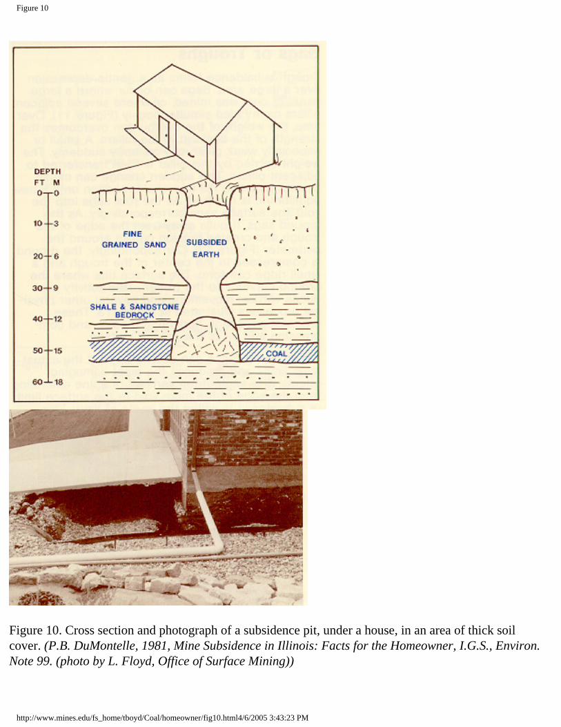
Figure 10
Figure 10. Cross section and photograph of a subsidence pit, under a house, in an area of thick soil cover. (P.B. DuMontelle, 1981, Mine Subsidence in Illinois: Facts for the Homeowner, I.G.S., Environ. Note 99. (photo by L. Floyd, Office of Surface Mining))
http://www.mines.edu/fs_home/tboyd/Coal/homeowner/fig10.html4/6/2005 3:43:23 PM
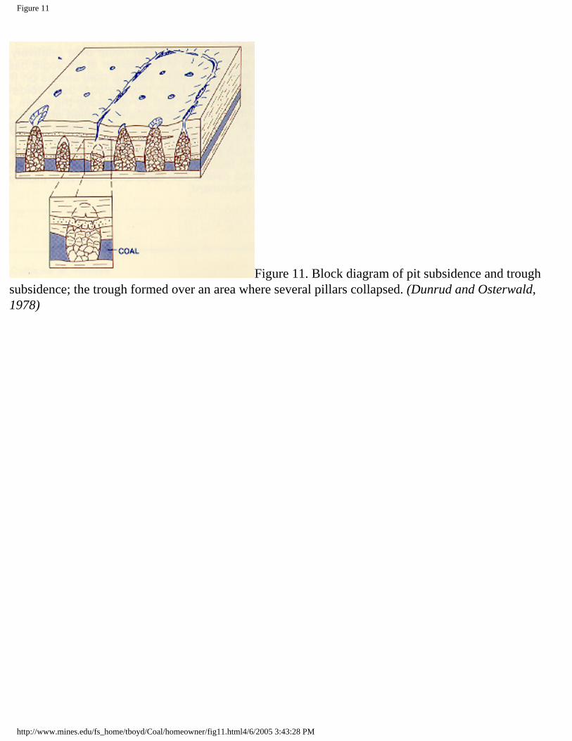
Figure 11
Figure 11. Block diagram of pit subsidence and trough subsidence; the trough formed over an area where several pillars collapsed. (Dunrud and Osterwald, 1978)
http://www.mines.edu/fs_home/tboyd/Coal/homeowner/fig11.html4/6/2005 3:43:28 PM
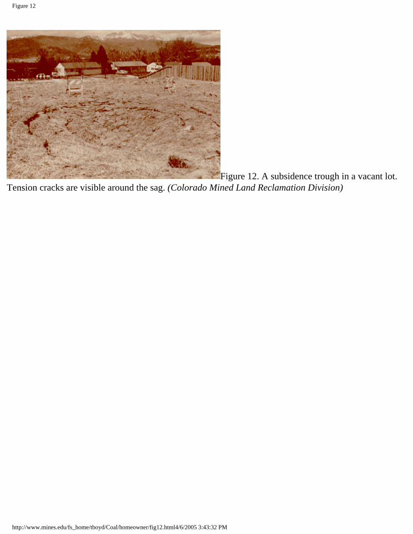
Figure 12
Figure 12. A subsidence trough in a vacant lot. Tension cracks are visible around the sag. (Colorado Mined Land Reclamation Division)
http://www.mines.edu/fs_home/tboyd/Coal/homeowner/fig12.html4/6/2005 3:43:32 PM
Figure 13
Figure 13. Cross-sectional view of roof caving, through subsidence above a large collapsed room and the effects on overlying rock. (S.S.Pang, 1981, Workshop on surface subsidence due to Underground Mining)
http://www.mines.edu/fs_home/tboyd/Coal/homeowner/fig13.html4/6/2005 3:43:34 PM
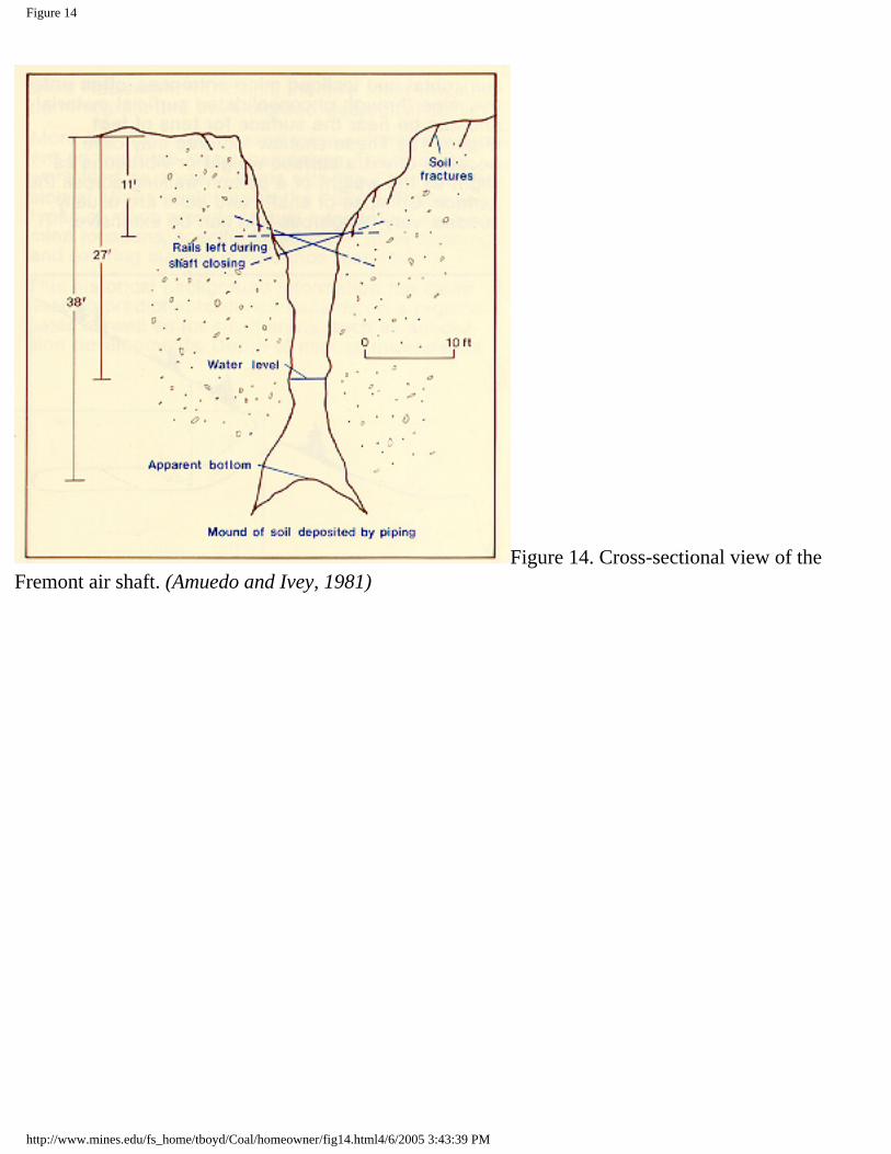
Figure 14
Figure 14. Cross-sectional view of the Fremont air shaft. (Amuedo and Ivey, 1981)
http://www.mines.edu/fs_home/tboyd/Coal/homeowner/fig14.html4/6/2005 3:43:39 PM

Figure 15
Figure 15. Cross-sectional view of an adit near a subdivision in Las Animas County. (Amuedo and Ivey, 1981)
http://www.mines.edu/fs_home/tboyd/Coal/homeowner/fig15.html4/6/2005 3:43:41 PM

Figure 16
Figure 16. Extent of Mining Map, 1:24,000 scale. The shaded areas are undermined; Y’s and boxes are adit and shaft locations; letters indicate that specific information is available for a mine. (Turney and Murray-Williams, 1983)
http://www.mines.edu/fs_home/tboyd/Coal/homeowner/fig16.html4/6/2005 3:43:46 PM

Figure 17
Figure17. Extent of Mining map, 1:50,000 scale. The shaded areas are undermined; Y’s and boxes are adit and shaft locations; letters indicate that specific information is available for a mine. (from Turney and Murray-Williams, 1983)
http://www.mines.edu/fs_home/tboyd/Coal/homeowner/fig17.html4/6/2005 3:43:49 PM
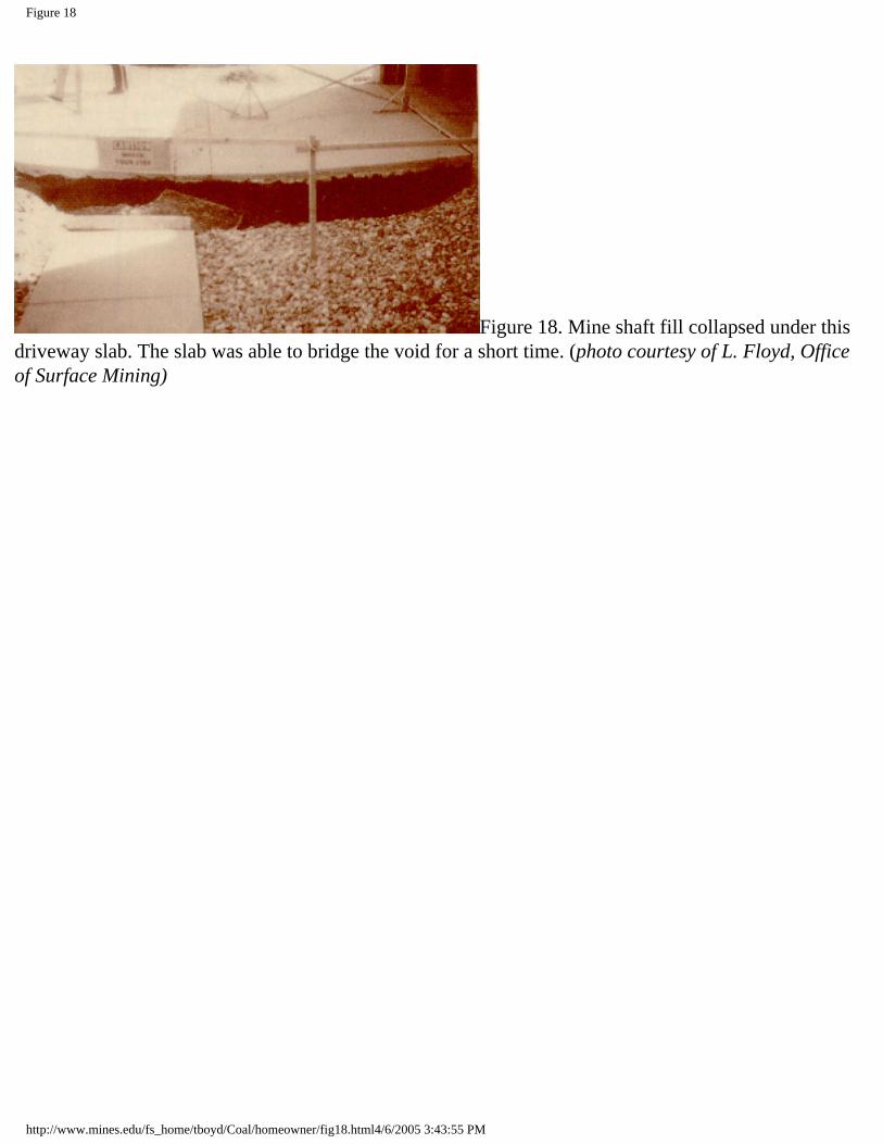
Figure 18
Figure 18. Mine shaft fill collapsed under this driveway slab. The slab was able to bridge the void for a short time. (photo courtesy of L. Floyd, Office of Surface Mining)
http://www.mines.edu/fs_home/tboyd/Coal/homeowner/fig18.html4/6/2005 3:43:55 PM
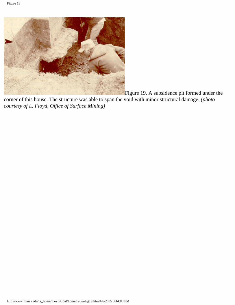
Figure 19
Figure 19. A subsidence pit formed under the corner of this house. The structure was able to span the void with minor structural damage. (photo courtesy of L. Floyd, Office of Surface Mining)
http://www.mines.edu/fs_home/tboyd/Coal/homeowner/fig19.html4/6/2005 3:44:00 PM
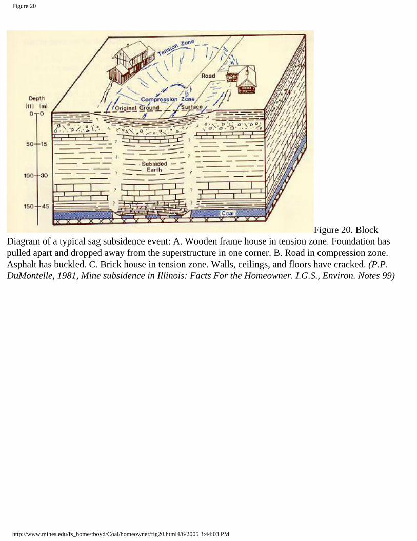
Figure 20
Figure 20. Block Diagram of a typical sag subsidence event: A. Wooden frame house in tension zone. Foundation has pulled apart and dropped away from the superstructure in one corner. B. Road in compression zone. Asphalt has buckled. C. Brick house in tension zone. Walls, ceilings, and floors have cracked. (P.P. DuMontelle, 1981, Mine subsidence in Illinois: Facts For the Homeowner. I.G.S., Environ. Notes 99)
http://www.mines.edu/fs_home/tboyd/Coal/homeowner/fig20.html4/6/2005 3:44:03 PM

Figure 21
Figure 21. A subsidence pit under the corner of a house. Note the utility being held up by string. (photo courtesy of L. Floyd Office of Surface Mining)
http://www.mines.edu/fs_home/tboyd/Coal/homeowner/fig21.html4/6/2005 3:44:06 PM

Figure 22
Figure 22. Tensional forces caused the steps and porch of this house to pull away from the main structure. (photo courtesy of Colorado Mined land Reclamation Division)
http://www.mines.edu/fs_home/tboyd/Coal/homeowner/fig22.html4/6/2005 3:44:10 PM
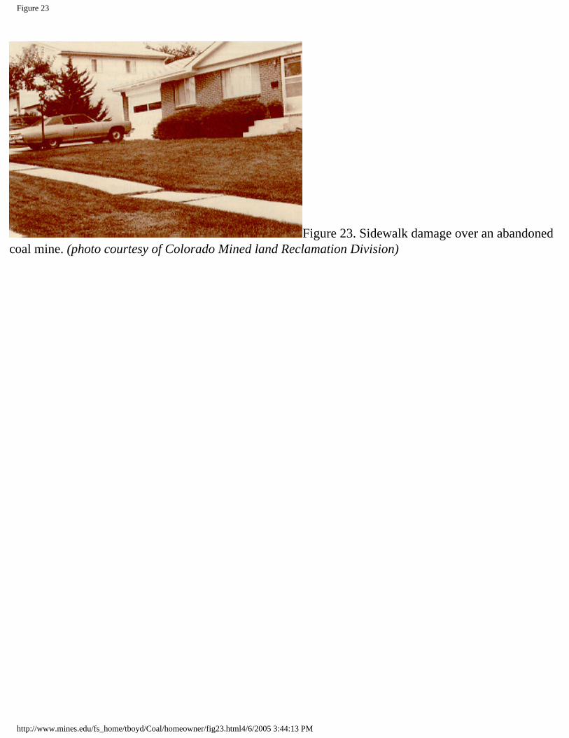
Figure 23
Figure 23. Sidewalk damage over an abandoned coal mine. (photo courtesy of Colorado Mined land Reclamation Division)
http://www.mines.edu/fs_home/tboyd/Coal/homeowner/fig23.html4/6/2005 3:44:13 PM

Figure 24
Figure 24. Typical major house damage from swelling soils. (from Holtz and Hart, 1978)
http://www.mines.edu/fs_home/tboyd/Coal/homeowner/fig24.html4/6/2005 3:44:19 PM

Figure 26
Figure 26a. Flexible gas coupling.
Figure 26b. Furnace and water heater flexible gas connections.
http://www.mines.edu/fs_home/tboyd/Coal/homeowner/fig26.html (1 of 2)4/6/2005 3:44:27 PM
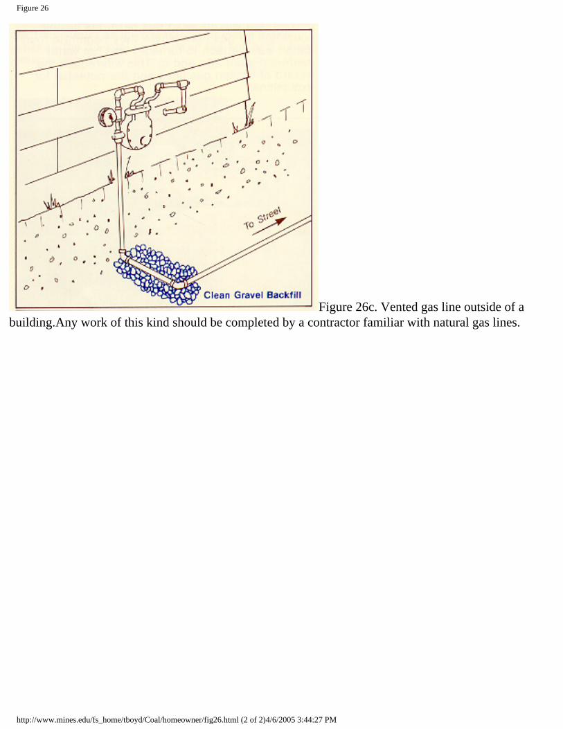
Figure 26
Figure 26c. Vented gas line outside of a building.Any work of this kind should be completed by a contractor familiar with natural gas lines.
http://www.mines.edu/fs_home/tboyd/Coal/homeowner/fig26.html (2 of 2)4/6/2005 3:44:27 PM
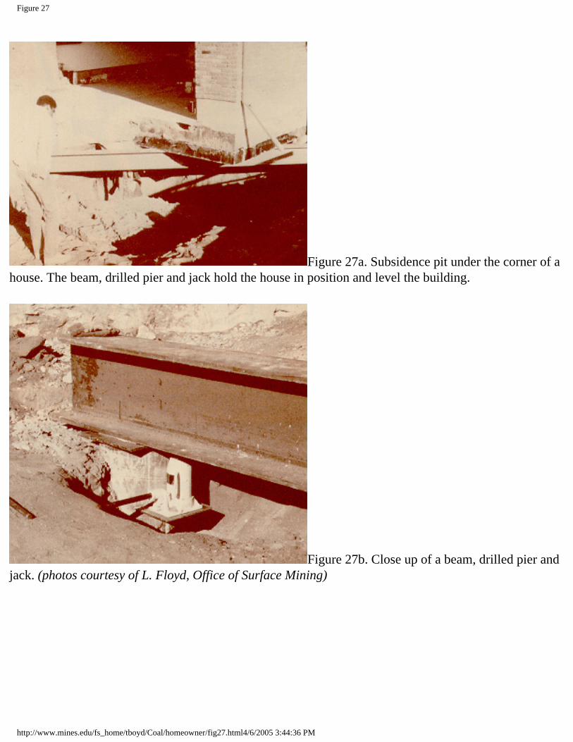
Figure 27
Figure 27a. Subsidence pit under the corner of a house. The beam, drilled pier and jack hold the house in position and level the building.
Figure 27b. Close up of a beam, drilled pier and jack. (photos courtesy of L. Floyd, Office of Surface Mining)
http://www.mines.edu/fs_home/tboyd/Coal/homeowner/fig27.html4/6/2005 3:44:36 PM
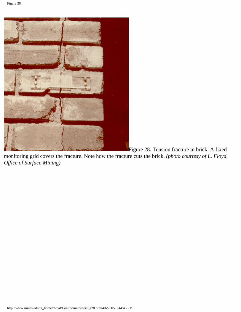
Figure 28
Figure 28. Tension fracture in brick. A fixed monitoring grid covers the fracture. Note how the fracture cuts the brick. (photo courtesy of L. Floyd, Office of Surface Mining)
http://www.mines.edu/fs_home/tboyd/Coal/homeowner/fig28.html4/6/2005 3:44:43 PM


![Coal Mine Subsidence Compensation Act 2017 - … · Page 2 Coal Mine Subsidence Compensation Act 2017 No 37 [NSW] Contents Page 18 Failure of proprietor of coal mine to comply with](https://static.fdocuments.in/doc/165x107/5b82c9427f8b9a31608bc8b3/coal-mine-subsidence-compensation-act-2017-page-2-coal-mine-subsidence-compensation.jpg)


