CO for thermal energy storage (TES) case studies
38
1 1 CO 2 mitigation accounting for thermal energy storage (TES) case studies 2 3 4 Luisa F. Cabeza 1 , Laia Miró 1 , Eduard Oró 1,* , Alvaro de Gracia 1 , Viktoria Martin 2 , 5 Andreas Krönauer 4 , Christoph Rathgeber 4 , Mohammed M. Farid 6 , Halime O. Paksoy 7 , 6 Mònica Martínez 8 , A. Inés Fernández 8 7 8 1 GREA Innovació Concurrent, Universitat de Lleida, Edifici CREA, Pere de 9 Cabrera s/n, 25001-Lleida, Spain, Phone: +34-973 003576, e-mail: 10 [email protected] 11 *Current address: Catalonia Institute for Energy Research, IREC, Jardins de les 12 Dones de Negre 1, 08930 Sant Adrià de Besòs, Barcelona, Spain 13 2 KTH, Royal Institute of Technology, Dept. of Energy Technology, Stockholm, 14 Sweden 15 4 Bavarian Center for Applied Energy Research (ZAE Bayern), Walther-Meissner- 16 Str. 6, 85748 Garching, Germany. e-mail: [email protected] 17 6 Department of Chemical and Materials Engineering, University of Auckland, 18 Auckland, New Zealand. Email:[email protected] 19 7 Department of Chemistry, Çukurova University, Turkey, Phone: +90-3223386418, e- 20 mail: [email protected] 21 8 Department of Materials Science & Metallurgical Engineering, Universitat de 22 Barcelona, Martí i Franqués 1-11, 08028-Barcelona, Spain, Phone: +34-934021298, e- 23 mail: [email protected] 24 25 26
Transcript of CO for thermal energy storage (TES) case studies
1
1
CO2 mitigation accounting for thermal energy storage (TES) case studies 2
3
4
Luisa F. Cabeza1, Laia Miró1, Eduard Oró1,*, Alvaro de Gracia1, Viktoria Martin2, 5
Andreas Krönauer4, Christoph Rathgeber4, Mohammed M. Farid6, Halime O. Paksoy7, 6
Mònica Martínez8, A. Inés Fernández8 7
8
1GREA Innovació Concurrent, Universitat de Lleida, Edifici CREA, Pere de 9
Cabrera s/n, 25001-Lleida, Spain, Phone: +34-973 003576, e-mail: 10
*Current address: Catalonia Institute for Energy Research, IREC, Jardins de les 12
Dones de Negre 1, 08930 Sant Adrià de Besòs, Barcelona, Spain 13
2KTH, Royal Institute of Technology, Dept. of Energy Technology, Stockholm, 14
Sweden 15
4Bavarian Center for Applied Energy Research (ZAE Bayern), Walther-Meissner-16
Str. 6, 85748 Garching, Germany. e-mail: [email protected] 17
6Department of Chemical and Materials Engineering, University of Auckland, 18
Auckland, New Zealand. Email:[email protected] 19
7Department of Chemistry, Çukurova University, Turkey, Phone: +90-3223386418, e-20
mail: [email protected] 21
8Department of Materials Science & Metallurgical Engineering, Universitat de 22
Barcelona, Martí i Franqués 1-11, 08028-Barcelona, Spain, Phone: +34-934021298, e-23
mail: [email protected] 24
25
26

2
Abstract27
28
According to the IPCC, societies can respond to climate changes by adapting to its 29
impacts and by mitigation, that is, by reducing GHG emissions. No single technology 30
can provide all of the mitigation potential in any sector, but many technologies have 31
been acknowledged in being able to contribute to such potential. Among the 32
technologies that can contribute in such potential, thermal energy storage (TES) is not 33
included explicitly, but implicitly as part of technologies such as energy supply, 34
buildings, and industry. To enable a more detailed assessment of the CO2 mitigation 35
potential of TES across many sectors, the group Annex 25 “Surplus heat management 36
using advanced TES for CO2 mitigation” of the Energy Conservation through Energy 37
Storage Implementing Agreement (ECES IA) of the International Energy Agency (AEI) 38
present in this article the CO2 mitigation potential of different case studies with 39
integrated TES. This potential is shown using operational and embodied CO2 40
parameters. Results are difficult to compare since TES is always designed in relation to 41
its application, and each technology impacts the energy system as a whole to different 42
extents. The applications analysed for operational CO2 are refrigeration, solar power 43
plants, mobile heat storage in industrial waste heat recovery, passive systems in 44
buildings, ATES for a supermarket, greenhouse applications, and dishwasher with 45
zeolite in Germany. The paper shows that the reason for mitigation is different in each 46
application, from energy savings to larger solar share or lowering energy consumption 47
from appliances. The mitigation potential dues to integrated TES is quantified in 48
kg/MWh energy produced or heat delivered. Embodied CO2 in two TES case studies is 49
presented, buildings and solar power plants. 50
51
52
53
Key words: CO2 mitigation potential, Thermal Energy Storage (TES), Operational CO2, 54
Embodied CO2, 55
56

3
1 Introduction57
58
According to the Intergovernmental Panel on Climate Change (IPCC), societies can 59
respond to climate changes by adapting to its impacts and by mitigation, that is, by 60
reducing Greenhouse Gas (GHG) emissions [1]. No single technology can provide all of 61
the mitigation potential in any sector, but many technologies have been acknowledged 62
in being able to contribute to such potential. Among these technologies thermal energy 63
storage (TES) is not included explicitly, but implicitly as part of technologies such as 64
energy supply (improved supply and distributions efficiency, renewable heat and power, 65
combined heat and power, concentrated solar power, etc.), buildings (more efficient 66
electrical appliances including heating and cooling devices, improved insulation, 67
passive and active solar design for heating and cooling, etc.), and industry (heat and 68
power recovery and advanced energy efficiency). 69
70
The benefits of TES may not be evident since their effects are not immediate in some 71
cases or they are only appreciable under specific circumstances. A first attempt on 72
accounting for TES potential energy savings and climate change mitigation was carried 73
out by Arce et al. [2]. In this study, an overview of the TES potential in Spain and 74
Europe was given by numerically demonstrating how TES can provide significant 75
energy and environmental benefits on national and continental scales. The sectors 76
considered were buildings (seasonal solar thermal systems, district/central heating, short 77
term solar thermal systems, and passive cold systems) and industry and transport 78
(combined heat and power, heating and cooling in industry, power stations and 79
transport, and concentrated solar power plants). Results showed how the potential load 80
reduction at the EU-level may be of 1,160,695 MWth during the next 10 years. Such 81
impact can exert a strong influence over power capacities to be installed over that 82
period. The share of Germany and Spain in this reduction is of 8% and 9%, 83
respectively. Yearly potential energy savings at the EU-level were estimated to be 7.5%. 84
Regarding electrical energy savings, Spain accounts for 20% of the overall savings at 85
the EU, which amounts to a 0.1% of the electrical energy consumption. Finally, the 86
estimated potential CO2 emissions reduction in the EU averaged 5.5% (based on 1990 87
and 2005 levels). 88

4
To enable a more detailed assessment of the CO2 mitigation potential of TES, across 89
many energy intensive sectors, the group Annex 25 “Surplus heat management using 90
advanced TES for CO2 mitigation” of the Energy Conservation through Energy Storage 91
Implementing Agreement (ECES IA) of the International Energy Agency (IEA) was 92
formed. This group focussed on the CO2 mitigation potential in several applications and 93
presented case studies with integrated TES. This potential is shown as operational and 94
embodied CO2. The aim of this paper is to present the results of the comprehensive 95
work conducted by the team members of Annex 25, carried out between 2011 and 2013. 96
The details of each application are discussed; nevertheless numbers are hard to compare 97
since TES is always designed in relation to its application, and each technology impacts 98
the energy system as a whole (e.g. national, or EU level) to various extents. 99
100
101
In order to incorporate eco-objectives into the design process of a product, additional 102
properties than the well characterized engineering properties are needed. These 103
properties (like embodied energy or CO2 footprint) include measures of the energy 104
committed and carbon released into the atmosphere when a material is extracted or 105
synthesised. 106
107
Embodied energy is the energy, excluding bio-fuels, that is used in making 1 kg of 108
material from its ores and feedstock in an industrial production plant. The CO2 footprint 109
is the sum of all the contributions per unit mass of usable materials existing in a plant. 110
In transport and in most industrial processes, there is a correlation, known as CO2 111
factor, between CO2 emissions and the energy consumption: 112
113
footprint ≅ 0.08Energy consumption
114
A commonly used value is a carbon footprint of 500 g CO2/kWh of electricity 115
production, coming from a developed country with an energy mix of 75% fossil fuel, 116
and a conversion efficiency of 38%, giving an oil equivalence of 7 MJ [3]. 117
118
Due to the low precision of the eco-attributes related to energy and carbon footprint, it is 119
accepted that there is an elevated uncertainty (of about 10 - 20% [3]) for decision 120
making. 121

5
The CO2 mitigation potential accounting is commonly carried out by counting the 122
energy used/saved and translating that to tons of CO2 using the CO2 emission factor. 123
But the CO2 emission factor depends on the country and on the year under investigation. 124
Usually, these issues are not considered, and authors only mention the country or group 125
of countries where the CO2 emission factor is used for, but scarcely the year. In this 126
article, the CO2 mitigation potential is shown using the operational and the embodied 127
CO2. Operational CO2 refers to the mitigated CO2 during the operation phase of the 128
component/application while the embodied CO2 refers to the CO2 released into the 129
atmosphere when the component/application is made. 130
131
Moreover, another key issue is the fact that CO2 emissions influence is rarely 132
considered when TES is studied in different applications. 133
134
135
2 OperationalCO2accountinginTEScasestudies136
137
A variety of technologies has been assessed in terms of the energy savings, and 138
resulting CO2 mitigation potential from integrating TES. The details of each application 139
are further discussed below, followed by a summarizing assessment. 140
141
In the examples discussed below, different TES technologies are used, sensible heat 142
storage and latent heat storage with phase change materials (PCM). In this section, each 143
technology is assessed in their respective country. More detail in these technologies can 144
be found elsewhere [4]. 145
146
2.1 Refrigerationapplications147
148
A model to estimate the potential Spanish and European impact when using TES for 149
cold production, in terms of energy consumption and CO2 emissions reduction, was 150
developed in a previous publication [5]. Table 1 shows all the cases analysed and the 151
electricity savings due to the implementation. The total energy demand for cold 152
applications in Spain and Europe was calculated, and after that the energy reduction and 153
therefore CO2 emissions mitigation was determined assuming a full implementation of 154

6
the PCM (phase change materials) TES systems (Figure 1). Two scenarios have been 155
studied, the low and the high scenario. The low scenario accounts for the lowest factors 156
of electricity savings, while the high scenario accounts for the highest values of energy 157
savings found in the literature. 158
159
Table 1. Potential electricity savings related in the maintenance of low temperature 160
sensitive products [5]. 161
Cases analysed Sector Authors Electricity savings
Domestic
refrigerators
Domestic and
commercial
sector
Azzouz et al.
[6]
During normal working
conditions, 10-30% COP
Domestic freezer Gin et al. [7] During defrost cycle by 8%, and
by 7% during door openings
Domestic
refrigerator
(refrigerator and
freezer)
Subramaniam
et al. [8]
During normal working
conditions by 8%
Refrigerated trucks
(PCM on the walls)
Cold in road
transport
Ahmed et al.
[9]
Daily average reduction of the
heat flux from the ambient to the
refrigerated truck of 16.3%
Refrigerated trucks
(novel refrigeration
system
incorporating
PCM)
Liu et al. [10]
During normal working
conditions between 6 and 38%,
depending on the chosen scenario
Industrial
refrigeration Cold in
industry
Cheralathan
et al. [11]
During normal working
conditions, 6-20% SEC (kW/TR)
Refrigeration
plants
Wang et al.
[12]
During normal working
conditions, 4-8% COP
162

1
1
1
1
1
1
1
1
1
1
1
1
1
1
1
1
1
1
164
Figu166
167
167
Amo173
of al174
energ175
betw176
these177
imple178
174
175
Figu177
178
178
Thus181
syste182
mitig183
ure 1. Poten
ong the cold
ll the secto
gy consump
ween 4,430 a
e economic
ementation
ure 2. Distr
s, in Spain,
ems may b
gation, these
ntial electri
d applicatio
ors analysed
ption, Spain
and 28,547 m
al saving a
of PCM-TE
ibution of t
the annual
e reduced
e emission
icity saving
ns identifie
d (Figure 2
n could save
millions of
re over esti
ES in the ac
the energy
(a) and E
CO2 emissi
from 4% t
reduction v
7
gs in cold a
[5].
ed, the indu
2). Related
e between 2
€, dependin
imated as t
ctual system
consumed
Europe (b),
ions from th
to 21%. In
values range
applications
ustry sector
to econom
239 and 1,76
ng on the sc
they do not
ms.
yearly for
, 2008 [5].
he cold stor
relation to
e from 5%
s using diff
shows the h
mical saving
60 millions
cenario eval
include th
cold applic
rage and co
o European
to 22%. Ev
ferent scena
highest pot
gs on their
of € and Eu
luated. How
he capital co
cations in S
old transport
n CO2 emis
ven though
arios
ential
final
urope
wever,
ost of
Spain
tation
ssions
on an

1
1
1
1
1
1
1
1
1
1
1
1
1
1
1
1
1
1
1
2
2
2
2
2
overa189
comp190
impo191
to in192
facto193
produ194
More195
grid 196
190
2.2 191
192
Powe201
parab202
Acco203
provi204
radia205
fluctu206
stora207
base 208
requi209
202
203
Figu205
206
all level th
pared to th
ortant that it
ndustry is p
or. Then, th
uction fact
eover, this i
stability.
Solarpo
ell and Edg
bolic troug
ording to th
ide power a
ation availab
uations in
age system
load therm
irement by
ure 3. Two-
he impact o
he total CO
t seems. On
probably du
he emission
tors have t
implementa
owerplan
gar [13] ca
gh CSP sy
hese author
at a constan
ble. By con
power outp
increases th
mal power
as much as
-tank direc
of the impl
O2 emission
ne can reali
uring peak
n factors b
to be acco
ation could c
nts
arried out a
ystem. The
rs, the use
nt rate despi
ntrast, a CSP
put, particu
he solar sha
output of
43%.
t TES syste
8
lementation
ns in 2008
ize that the
hours and
become mu
ount instea
come to alle
a dynamic
system co
of a therm
ite significa
P system w
ularly durin
are of the p
f 1 MW. T
em used wi
field [13].
n of PCM-T
8 in Europe
domestic c
therefore p
ch higher
d of the e
eviate the pe
simulation
onsidered
mal storage
ant disturba
without therm
ng intermitt
power plant
This reduce
ith a parab
TES system
e, it could
old and som
produced w
because he
energy mix
eak load an
for a TES
is presente
gives the s
ances in the
mal storage
ent cloud c
t by as muc
es the sup
bolic trough
ms is barely
be much
me of the en
with higher
ere the mar
x factors b
nd hence imp
S unit used
ed in Figu
system abil
amount of
undergoes
cover. Add
uch as 47%
pplementary
h solar colle
y 1%
more
nergy
r CO2
rginal
being.
prove
d in a
ure 3.
ity to
f solar
large
ding a
for a
y fuel
ector

2
2
2
2
2
2
2
2
2
2
2
2
2
2
2
2
A su213
The 214
share215
as m216
are m217
bene218
using219
4). 220
214
215
Varia
Solar
deliv
load
Supp
fuel
(MW
Solar
216
217
218
Figu220
cl221
221
ummary of t
results of th
e (the fracti
much as 47%
more meagr
fit of therm
g the storag
Table
able
r energy
vered to
(MWh)
plemental
required
Wh)
r share (%)
ure 4. Tota
oudy day f
the results o
hese simula
ion of energ
% to levels
re on cloud
mal energy s
ge tank as a
e 2. Summa
System
TES
16.4
12.5
47.6
al solar ener
for: left – sy
obtained by
ations show
gy provided
over 70% o
dy days. Ho
storage is th
buffer betw
ary of resul
Clear da
m w/o
S
S
48
58
6
rgy availab
ystem with
9
y Powell an
w that, by ad
d by solar) o
on a sunny
owever, dur
he ability to
ween availab
lts obtained
ay
System with
TES
16.82
7.18
70.1
ble and ene
out storage
nd Edgar [13
dding 8 h of
of the powe
day. The im
ring intermi
o maintain
ble energy
d by Powell
h Syste
T
8
15
3
ergy deliver
e; right – sy
3] are prese
f storage ca
er plant can
mprovemen
ttent cloud
a constant p
and energy
l and Edga
Cloudy
em w/o
TES
8.40
5.78
4.3
red to the lo
ystem with
ented in Tab
apacity, the
n be increas
nts in solar
cover, the
power outp
y demand (F
ar [13].
y day
System w
TES
8.49
15.51
35.4
oad on a pa
h storage [1
ble 2.
solar
ed by
share
main
put by
Figure
with
artly
3].

10
From results presented in Table 2, the mitigation of CO2 emissions in a CSP plant when 221
TES is implemented can be calculated as a function of the fuel used for hybridation 222
(Table 3). Since the supplementary fuel requirement is reduced by 43%, CO2 emissions 223
will be also reduced by 43%. 224
225
Table 3. CO2 emissions (tCO2) in a 1 MW output CSP plant with and without TES. 226
Variable Emission factor of
the fuel considered,
tCO2/TJ
System w/o TES System with TES
Supplemental
fuel required
(MWh)
--- 12.58 7.18
CO2 emissions
(tCO2)
Coal
(94.6-96.1 [14])
4.28 – 4.35 2.45 – 2.48
Natural gas
(56.1 [14])
2.54 1.45
Oil
(73.3-77.4 [14])
3.32 – 3.51 1.89 – 2.00
227
2.3 Mobileheatstorageinindustrialwasteheatrecovery228
229
Transport of heat by truck, train or boat, “heat on wheels”, is a promising supplement to 230
the currently used systems of piped thermal energy distribution or of use of waste heat 231
from industry (Figure 5). The concept requires that the heat can be stored in a material 232
with a high energy density, i.e. a large amount of heat per unit of weight and volume. 233
Mobile energy storage systems transported by truck may bridge the gap between heat 234
source and demand site in cases where a pipeline-bound connection cannot be realized 235
cost effectively. 236
237

11
238
Figure 5. Schematic description of the heat on wheels concept [15]. 239
240
Based on this result ZAE Bayern and its partner Industrieanlagen Hoffmeier GmbH 241
have developed and built a prototype of a mobile storage based on an open sorption 242
system, working with a packed bed of zeolite as adsorbent. A pilot plant with a waste 243
incineration plant as a heat source and an industrial drying process as demand site was 244
built (Figure 6). The system has been operated for about 50 cycles so far and the test 245
period is still running. 246
247
248
Figure 6. Principle of Mobile Sorption Heat Storage in Industrial Waste Heat 249
Recovery [15]. 250
251
LargeScaleCHP Utility
GBiomass
heat
Heat on wheels
Heat on wheels
Heat Carrier Return, 45 ◦C
Boiler(supple‐mental heat)
T [◦C] < T_mp
Accumulator
Charging Accumulator
DischargingAccumulator
Heat Carrier Supply, 90 ◦C
Heat Supply
Transport
Heat Demand
Small ScaleCHP Utility
MobS MobS MobS
Waste Heat
Charging station
Trans- port
Discharging station
User

12
Table 4 contains the necessary parameters to estimate the potential CO2 mitigation 252
achieved by this mobile sorption heat storage. 253
254
Table 4. Parameters for CO2 mitigation accounting. 255
256
The energy savings are equal to the amount of substituted gas (2.62 MWh) accounted as 257
the energy content per storage (2.91 MWh) times the storage efficiency (90%). 258
Multiplied with the corresponding CO2 emissions factor, 530 kg CO2 savings per 259
storage can be achieved. However, CO2 emissions due to auxiliary electric energy (85 260
kg CO2) and. the fuel consumption of the truck (29 kg CO2), have to be subtracted, thus 261
the total amount of CO2 mitigation per container is 416 kg CO2. Considering annual 262
storage handling, the amount of CO2 mitigation per storage container per year will be 263
437 t CO2. 264
265
If 10 to 100 mobile heat storage systems could be established in Germany in the 266
medium term the potential CO2 mitigation in Germany would be around 4,000 – 40,000 267
tons CO2 per year. This range refers to the physical potential of CO2 mitigation while 268
the other applications studied in this paper refer to technical potentials, as defined in [1]. 269
270
Storage
Energy content per storage [MWh] 2.91
Storage efficiency 0.9
Boundary conditions
Distance [km] (one way) 10
Auxiliary electric energy / cycle [MWh] 0.11
Specific fuel consumption truck [l/100km] 55
Annually number of storage handling 1,051
CO2 emission factors
gas [kg CO2/MWh] 202
electricity [kg CO2/MWh] 773
fuel (diesel) [kg CO2/l] 2.64

13
Similarly, the transport of excess heat from a large-scale biomass- based combined heat 271
and power plant to local smaller “boiler-based” utilities has been studied by the Swedish 272
District Energy System. Initially, the market for heat transportation with truck (train or 273
boat) was assessed by considering statistics on cities with population and connected to 274
district heating systems. Other assumptions were that the single household on average is 275
occupied by 2.5 persons and utilizes 20 MWh of heat per year. 276
277
Here, the market results show that smaller cities (between 200 and 10,000 inhabitants) 278
with district heat already in place, generate a yearly heat demand of about 11 TWh. If 279
the total demand would be provided by energy transport from the large CHP utility, the 280
additional biomass-based power generation in these plants would amount to about 7 281
TWh. The effect on CO2 mitigation on such scenario can be analysed as follows: 282
283
1. CO2 mitigation is obtained through replacing heat and electricity generated by 284
green alternatives. This is due to: 285
a. Replacing heat from an oil-based boiler (approximately 300 g/kWh) by 286
heat from biomass CHP. 287
b. Replacing electricity from EU average mix (approximately 350 g/kWh), 288
with zero CO2-emission power from biomass CHP. 289
For this case, the expected CO2 mitigation is 5.8 Mt/year, which is about 10% 290
of the present Swedish total annual CO2-emissions. 291
292
2. CO2 mitigation is obtained through the generation of electricity only since heat 293
is normally generated in a local, smaller-scale biomass boiler. 294
For this case, the expected CO2 mitigation is 2.4 Mt/year for Sweden. 295
296
2.4 Passivesystemsinbuildings297
298
It is well known that the use of latent heat storage in building passive systems could 299
reduce the energy consumption of the HVAC systems. These reductions have been 300
analysed both experimentally and numerically. 301
302
In summer, during daytime the sunshine and high temperatures result in a heat wave 303
penetrating the walls of the buildings (Figure 7). PCM absorbs the excess of heat 304

3
3
3
3
3
3
3
3
3
3
3
3
3
3
3
3
3
3
3
3
3
throu311
reduc312
and 313
temp314
proce315
comf316
312
313
314
315
316
Table319
perfo320
quan321
320
From323
estim324
of 23325
324
Table326
consi327
ugh its melt
cing its pea
the coolin
peratures be
ess to both
fortable, clo
F
e 5 shows
ormance of
ntify the ene
m the energy
mated. Acco
38 g/kWh is
e 5 present
idering a se
ting proces
ak. During
g system c
ecome lowe
internal and
osing the cy
Figure 7. Op
s measured
f different c
ergetic bene
y consumed
ording to the
s used for th
ts CO2 emi
et point of
s, delaying
most of the
consumes l
r, the PCM
d external e
ycle and bein
perating pr
d data of e
cubicles loc
fits of using
d in each cub
e Spanish e
his estimatio
issions and
24 ºC durin
14
the heat w
e day the r
less energy
M releases th
environment
ng ready fo
rinciple of
energy con
cated in Pu
g PCM [16]
ubicle, the C
electricity pr
on.
d electrical
ng 90 days
wave penetra
oom tempe
y. During
he stored he
ts, keeping
r another da
PCM in bu
nsumption
uigverd de
].
CO2 emissio
roduction sh
energy sav
per year (c
ating the bu
erature rema
night time
eat through
again the ro
aily use.
uildings [15
and compa
Lleida (Sp
ns to the atm
hare, a CO2
vings for di
cooling dem
uilding, and
ains comfor
, when ou
its solidific
oom temper
5].
ares the en
pain) in ord
mosphere c
2 emission f
ifferent cub
mand). The
d also
rtable
utdoor
cation
rature
nergy
der to
can be
factor
bicles,
study

15
presents the performance of a cubicle with traditional constructive system without 326
insulation (REF), with 5 cm of polyurethane (PU), with polyurethane and PCM 327
(RT27+PU), a system without insulation but with high thermal mass (Alveolar) and the 328
same system with PCM (SP25+Alveolar). The constructive systems of the different 329
cubicles are detailed in Castell et al. [16] 330
331
Table 5. CO2 emissions to the atmosphere due to the electricity consumption in 332
each cubicle [16]. 333
Electricity
consumption
(kWh/year·m2)
CO2 emissions
(kg/year·m2)
CO2 savings
(kg/year·m2)
Reference 29.3 7.0 0.0
PU 14.3 3.4 3.6
RT27+PU 12.2 2.9 4.1
Alveolar 15.8 3.8 3.2
SP25+Alveolar 13.1 3.1 3.9
334
335
Moreover, the same experimental set-up was used to test the energy performance of a 336
ventilated double skin facade (VDSF) with macro-encapsulated panels with PCM inside 337
its air cavity. This system was designed to reduce the heating demand during the winter 338
season. The VDSF acts as a solar collector during the sunny hours and once the PCM is 339
melted and the solar energy is needed by the building heating demand, the heat stored is 340
discharged to the inner environment as a heating supply. According to de Gracia et al. 341
[17] the electrical energy required by the heat pump to maintain a set point of 21 ºC 342
during heating season is reduced by 20.6% due to the use of this VDSF. 343
344
Table 6 quantifies the amount of CO2 emissions that would be saved due to the use of 345
PCM in this active system. An energy mix of 238 g CO2/kWh is also considered in this 346
case. 347
348
349
350

16
Table 6. CO2 emissions to the atmosphere due to the energy consumed in each 351
cubicle [17]. 352
Energy
consumption
(kWh/year·m2)
CO2 emissions
(kg/year·m2)
CO2 savings
(kg/year·m2)
Reference 191.8 45.6 0.0
VDSF 152.1 36.19 9.4
353
Moreover, the thermal performance of a single family house with and without PCM, 354
impregnated in the gypsum board, was numerically investigated in 10 different cities 355
around the world with different climates [18]. The paper discusses the influence of the 356
climate in the potential that PCM can provide for energy savings. Table 7 presents the 357
energy savings achieved under the different climate conditions. 358
359
Table 7. Electricity consumption of the house and the energy savings provided by 360
the PCM [18]. 361
362
Country Energy per year
(no PCM) [GJ]
Savings per
year (with
PCM) [GJ]
Savings per
year (%)
Bogota 8.39 2.60 31
Quito 7.27 2.40 33
San Francisco 14.62 1.90 13
Auckland 13.64 1.50 11
Brisbane 14.00 1.40 10
Montreal 110.00 1.10 1
Madrid 27.50 1.10 4
Stockholm 45.00 0.90 2
Kuala Lumpur 15.00 -0.30 -2
Singapore 20.00 -0.40 -2
363
These savings in the electrical energy needed to achieve thermal comfort conditions 364
during the whole year (set point of 20 ºC for heating and 23 ºC for cooling) represent 365

17
reductions in the amount of CO2 emitted to the atmosphere. According to IEA [19] the 366
worldwide CO2 emissions per kWh from electricity generation present slight variation 367
during the last 20 years, presenting a value of 564 gCO2/kWh for 2010. Moreover, the 368
IEA report also provides the energy mix of each country. Table 8 presents the amount of 369
CO2 that has been saved at the different analysed locations if considering a global 370
worldwide energy mix and a country ratio. One can see that for some locations, the 371
amount of CO2 saved is very different depending on the chosen CO2 emission factor. 372
373
Table 8. CO2 reduction from space heating and cooling considering a global 374
worldwide energy mix [18]. 375
City (Country)
CO2 reduction
[kgCO2/year·m2]
Worldwide
energy mix
CO2 reduction
[kgCO2/year·m2]
Country energy
mix
Bogota
(Colombia) 1.59 0.50
Quito (Ecuador) 1.47 1.01
San Francisco
(USA) 1.16 1.08
Auckland (New
Zealand) 0.92 0.24
Brisbane
(Australia) 0.86 1.28
Montreal
(Canada) 0.67 0.22
Madrid (Spain) 0.67 0.28
Stockholm
(Sweden) 0.55 0.03
Kuala Lumpur
(Indonesia) -0.18 -0.24
Singapore
(Singapore) -0.25 -0.22
376
18
A similar experimentation was carried out in a 4 m2 floor area test cabin in Adana, with 377
cooling and heating loads 2391 W and 665 W, respectively [20,21]. In this case, two 378
microencapsulated PCM - Micronal 5001 (melting point 26 °C and latent heat 110 379
kJ/kg) and Micronal 5008 (melting point 23 °C and latent heat 110 kJ/kg) – were used 380
to produce sandwich panels with insulation material Izopan. The south facade of the test 381
cabin was lined with sandwich panel. Total amount of PCM used was 3.5 kg. The tests 382
were carried out with PCM only, insulation only and sandwich panel linings. In 383
summer, day-time temperature in the cabin was reduced by 2.5 °C in the case of using 384
PCM only and 0.6 °C when only using insulation. Cooling loads were reduced by 7 % 385
as a result of using PCM in the summer operation, which accounts for energy saving of 386
186 kWh/year. In winter, the average temperature inside the cabin was increased by 1.6 387
°C with PCM only, 1.3 °C with only insulation and 2.2 °C with sandwich panel 388
(insulation together with PCM). Under these conditions, heating loads were reduced by 389
10% and 23% when PCM and sandwich panel were used, respectively. Energy 390
conserved for heating was 292 kWh/year. 391
392
Calculating the heating using coal and air-conditioning using electricity produced from 393
coal, the CO2 mitigation in the cases presented in Table 8 was 0.5 ton/year as average. 394
395
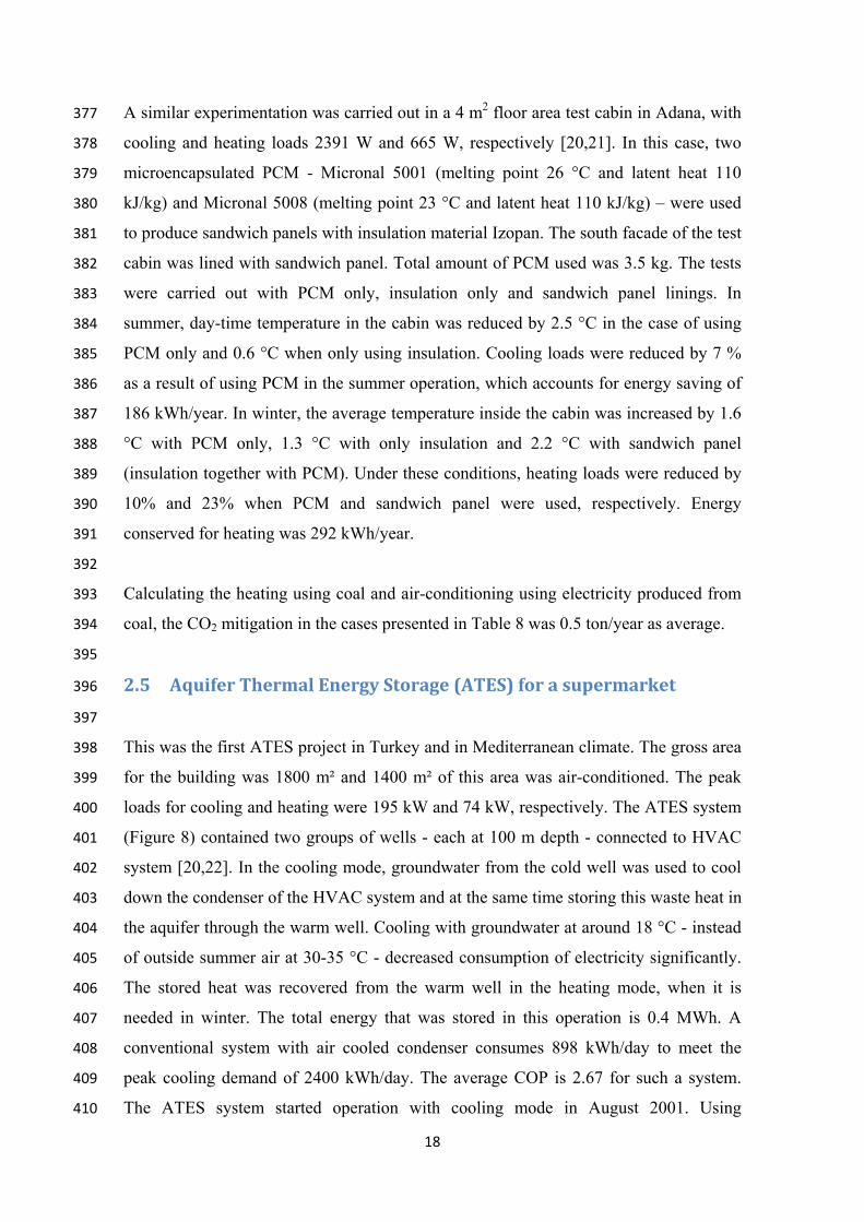
2.5 AquiferThermalEnergyStorage(ATES)forasupermarket396
397
This was the first ATES project in Turkey and in Mediterranean climate. The gross area 398
for the building was 1800 m² and 1400 m² of this area was air-conditioned. The peak 399
loads for cooling and heating were 195 kW and 74 kW, respectively. The ATES system 400
(Figure 8) contained two groups of wells - each at 100 m depth - connected to HVAC 401
system [20,22]. In the cooling mode, groundwater from the cold well was used to cool 402
down the condenser of the HVAC system and at the same time storing this waste heat in 403
the aquifer through the warm well. Cooling with groundwater at around 18 °C - instead 404
of outside summer air at 30-35 °C - decreased consumption of electricity significantly. 405
The stored heat was recovered from the warm well in the heating mode, when it is 406
needed in winter. The total energy that was stored in this operation is 0.4 MWh. A 407
conventional system with air cooled condenser consumes 898 kWh/day to meet the 408
peak cooling demand of 2400 kWh/day. The average COP is 2.67 for such a system. 409
The ATES system started operation with cooling mode in August 2001. Using 410

4
4
4
4
4
4
4
4
4
4
4
4
4
4
4
4
4
4
4
4
4
groun419
than 420
syste421
inves422
decre423
574.2424
syste425
113 t426
420
421
422
2.6 423
424
Ener428
fruits429
impo430
resou431
429
In 20432
m2 a433
green434
ndwater at
that of con
em was do
stment that
ease on inv
2 kWh/day
em was 118
ton/year of
Greenho
rgy managem
s, vegetable
ortant as we
urces, and fo
007 two sep
at Cukurov
nhouses wa
18°C yield
ventional sy
own-sized,
t was requi
vestment of
y. Total an
MWh. Ass
CO2 mitiga
Figure
ouseappl
ment in com
es, and orn
e address th
food produc
parate green
a Universit
as heated a
ded an avera
ystem. Beca
making the
ired for dr
heat pump
nnual electr
suming that
ation.
e 8. ATES s
lications
mmercial gr
amental pla
e need for s
tion for all,
nhouses with
ty (Turkey)
and cooled
19
age COP o
ause of 60%
e system m
rilling of th
. With this
rical energy
electricity i
system for s
reenhouses
ants. It is a
sustainable
in combine
h polyethyl
) research
by ATES
of 4.18, whi
% higher CO
more econo
he wells w
performanc
y conserva
is produced
supermark
aims at ens
an issue tha
energy serv
e.
ene covers,
farm were
technique
ich was alm
OP, heat pum
omically vi
was cancelle
ce ATES sy
ation introd
d with coal,
ket [22].
suring susta
at will beco
vices, conse
each havin
used [20,2
and the ot
most 60% h
ump of the A
iable. The
ed out wit
ystem cons
duced by A
this would
ainable grow
ome increas
ervation of
ng an area o
23]. One o
ther one w
higher
ATES
extra
h the
umed
ATES
mean
wth of
singly
water
of 360
of the
with a

4
4
4
4
4
4
4
4
4
4
4
4
4
4
4
4
4
4
4
4
4
4
4
conv437
opera438
heat 439
cooli440
schem441
438
439
440
441
Temp455
mont456
ATE457
recov458
GJ. I459
30-3460
temp461
toma462
store463
temp464
cooli465
weig466
opera467
Addi468
ventional he
ated for the
stored from
ing in summ
matic diagra
Figure 9
peratures in
ths in this
ES system op
very and co
In this heat
5 °C. Heat
peratures w
atoes). Tota
ed was reco
perature ins
ing. The pr
ght- was 40
ation of AT
itionally, it
eating system
e ATES gre
m summer to
mer. Greenh
am of the A
9. Schemati
n the green
climate. W
perated dur
old storage.
t storage pr
t stored wa
were below
l energy sto
overed for c
side the gre
roduct yiel
% higher th
TES system
t was pos
m and no co
enhouse. Th
o heat the gr
house was th
ATES system
ic diagram
nhouse vari
Winter air co
ring 2005-20
Total energ
ocess, grou
as recovered
11 °C (m
ored in the c
cooling of th
eenhouse e
ld of tomat
han those f
m in 2005-2
sible to c
20
ooling. Two
he basic co
reenhouse -
he “solar co
m is shown
of the ATE
ied betwee
older than
006 for 70 d
gy stored in
undwater tem
d in winter
minimum t
cold well d
he greenho
exceeded 30
toes in the
for the conv
2006, no f
cool the gr
o wells- a co
oncept of th
- as well as
ollector” to
in Figure 9
ES system f
n 40-60 °C
10 °C is th
days storing
the warm w
mperature i
r to heat th
emperature
during heat r
use for 32
0°C, the A
e ATES gr
ventional gr
fossil fuel f
reenhouse
old and a w
e ATES sys
the cold sto
store heat i
.
for greenho
C about 6
he source f
g heat and f
well in this p
increased fr
he greenhou
allowable
recovery wa
days in spr
ATES system
eenhouse-in
reenhouse.
for heating
in a perio
warm well –
stem utilize
ored in wint
in sunny da
ouse [23].
hours/day
for cooling
for 138 days
period was
rom 18-20
use, when i
e for grow
as 76.0 GJ.
ring 2006. W
m was use
n terms of
During the
was consu
od when u
– were
ed the
ter for
ays. A
for 5
. The
s heat
103.9
°C to
inside
th of
Cold
When
ed for
f fruit
e total
umed.
under

4
4
4
4
4
4
4
4
4
4
4
4
4
4
4
4
4
4
4
4
4
4
4
4
4
4
4
4
4
Medi461
from462
fuel o463
and p464
for h465
MWh466
462
Cons467
could468
7x10469
can b470
Acco471
468
Ener474
consi475
heat 476
heati477
integ478
colle479
475
476
477
478
This 484
simu485
20% 486
cove487
heati488
annu489
iterranean c
m the harves
oil No.6. F
pumps for
heating and
h/year.
sidering tha
d be saved i
07 m2 in 200
be reduced
ordingly 163
rgy manage
idered, imp
is harveste
ing through
gration a PV
ecting heat.
concept w
ulations. Th
of the ann
r about 20
ing/electrici
ual CO2 miti
climate con
st was incre
For the ATE
groundwate
cooling we
at greenhou
in every gre
05. With in
by 5 millio
3 million U
ement in
plementing t
ed instead o
seasonal st
VT-panel as
This concep
Figure 10.
was analyse
is showed t
nual heating
0% of the
ity generati
igation as sh
nditions pro
eased furthe
ES system 3
er circulatio
ere 7.6 and
uses in Turk
eenhouse. T
ntroduction
on tons /yea
USD worth o
a greenhou
the closed g
of ventilated
torage. For
s a shading
pt is schema
Schematic
ed based o
that the har
g demand,
electricity
on that is r
hown in Tab
21
oduction wo
er. The conv
3 MWh of e
on. For 200
3.2, respec
key are hea
The total gre
of ATES s
ar with an
of fuel oil w
use located
greenhouse
d, stored an
this study, t
device, gen
atically illu
c profile vie
on annual
rvested exc
at the same
demand a
replaced, th
ble 9.
ould have b
ventional gr
electricity w
05-2006 ope
ctively. Tota
ated with fu
eenhouse ar
ystems in g
extra inves
would be sav
d in Nordi
concept [24
nd used at a
the means o
nerating ele
strated in F
ew of solar
energy per
ess heat co
e time as e
as well. De
hese saving
been halted.
reenhouse w
was used to
eration of t
al energy co
uel oil, 26
ea in Turke
greenhouses
tment of 28
ved per year
ic climate
4]. Here, the
a later time
of harvestin
ectricity at t
igure 10.
blind [24].
rformance
ould be used
electricity w
epending o
gs can be tr
. Thus, the
was heated
run the fan
the system,
onserved w
ton/year of
ey was more
s, CO2 emis
80 million U
r.
has also
e summer e
e, e.g. for w
ng was by w
the same tim
.
using TRN
d to cover
was generat
on the mod
ranslated in
yield
using
n coils
COP
was 36
f CO2
e than
ssions
USD.
been
excess
winter
way of
me as
NSYS
about
ted to
de of
nto an

22
Table 9. A comparison in CO2 reduction for closed greenhouse with and without 484
considering the solar blind system [24]. 485
Conventional Greenhouse
Energy Source
Biomass Fuel Oil Electricity Natural Gas
Closed Greenhouse without
solar PVT blind
-11% 74% 62% 71%
Closed greenhouse WITH
solar PVT blind
26% 83% 74% 81%
486
As shown, the values are also there for a closed greenhouse where the heat is not 487
harvested using solar PVT blinds [25]. Then, more of the annual heating demand can be 488
covered (over 50%) but no electricity is generated in the process. For this case, heat is 489
collected at much lower temperature and thus an electrical heat pump is needed to adjust 490
the temperature of the heat. Then, the closed greenhouse might even have a negative 491
impact on climate mitigation if the harvested, stored excess heat would replace heat 492
from a biomass boiler. This means the CO2 emission is not reduced in comparison with 493
the conventional greenhouses in this case. However, combining the closed greenhouse 494
with the solar blind system such that a portion of the electrical demand is provided by 495
the PVT panels, the CO2 emission can be reduced by 26% as compared to a 496
conventional greenhouse using biomass for heating. Furthermore, more than 74% CO2 497
emission reduction can be achieved in case of using fuel oil, electricity and natural gas 498
as the external energy source for heating purpose in the greenhouse. These numbers all 499
assume the EU27 Energy Mix for Power Generation. 500
501
2.7 DishwasherwithzeoliteinGermany502
503
Open adsorption systems using water as adsorbate, zeolite as adsorbent and air as heat 504
and mass carrier can be used for heating, cooling and thermal energy storage (TES). 505
Drying processes are a promising field of application for open adsorption systems, since 506
air can be dehumidified in an adsorption cycle. For example, the energy consumption of 507
dishwashers can be reduced by means of an open adsorption system [26]. Therefore, the 508
water heating phase of the main washing cycle has been used to desorb a packed bed of 509
zeolites. The common water heating phase before the drying of the dishes has been 510

23
omitted and replaced by an adsorption phase in which the dishes are dried by hot air. In 511
this context the adsorption system was used as a thermally driven heat pump and a 512
thermal energy storage system. The reduction of the energy consumption compared to a 513
conventional dishwasher from about 1.05kWh to 0.80kWh per washing cycle leads to 514
energy savings of about 24 % [26]. This innovative dishwasher is commercially 515
available since November 2009. 516
517
The assumptions made in the CO2 mitigation calculation of this system were: energy 518
savings of 0.25 kWh per washing cycle and an average of 250 washing cycles per year 519
with a dishwasher lifetime of 10 years. A CO2 emissions factor of 0.5 kg CO2/kWh was 520
considered. An annual number of 1 million installed dishwashers with zeolite drying is 521
considered in order to demonstrate the potential energy savings and CO2 mitigation due 522
to a wide application of this TES system. Calculated energy and CO2 emissions savings 523
are presented in Table 10. 524
525
Table 10. Energy and CO2 savings due to an extensive use of a sorption storage 526
system for dishwashers. Detailed boundary conditions are given in the text. 527
Savings After 1st year After 10 years (cumulative
value)
Energy 62.5 GWh 3,440 GWh
CO2 emissions 31,250 tons 1.7 megatons
528
Today, some dishwashers with zeolite drying only consume around 0.73 kWh of 529
electricity per cycle and, hence, lie 10% below the limits for the top-grade energy 530
efficiency class A+++ [27]. 531
532
In a recent study by Santori et al. [28], a silica gel was investigated as an adsorbent 533
material for the drying stage of a dishwasher. Tests of an optimized prototype showed 534
an electric power consumption of 0.636 kWh corresponding to a reduction of energy 535
consumption of about 40% compared with the standard cycle of an energy class A 536
standard dishwasher (1.08 kWh according to [28]). 537
538
24
Therefore, assuming higher energy savings of 0.4 kWh per washing cycle and 250 539
cycles per year, the cumulative energy and CO2 emission savings after 10 years would 540
be approx. 5,500 GWh and 2.8 megatons per 1 million dishwashers, respectively. 541
3 EmbodiedCO2accountinginTEScasestudies542
543
The embodied energy is the energy that must be committed to produce a unit mass of a 544
material from whatever it is made from. It includes the embodied energy involved in the 545
extraction, primary production, transformation, transport to its place of use and 546
recycling [29]. Similarly to operational CO2, to translate the embodied energy into 547
embodied CO2 in any application, the energy mix factor should be used. 548
549
3.1 Buildings550
551
By using the CES Selector software the relation between the embodied energy vs. the 552
CO2 footprint of the primary production of several typical building materials can be 553
plotted as shown in Figure 11 [30]. The same type of data can be obtained for the 554
processing and recycling of the materials. But usually, more data is necessary to assess, 555
compare and select different materials, and e.g. water usage in its production (Figure 556
12). 557
558
Jiao et al. [31] analysed different type of buildings and the materials involved. They 559
reported that more than 90% of a building is concrete (Figure 13). The remaining 10% 560
of materials, are brick, wood and steel among some others. 561
562

5
5
5
5
5
5
564
565
566
567
F568
569
Figure
Figure 12.
1
Embo
died
ene
rgy,
prim
ary
prod
uctio
n (M
J/kg
)
0.1
1
10
100
11. Embod
Embodied
Soda lime glas
Concrete (
Sandstone
Marble
died energy
energy and
10
Cemen
Mineral wool_T-gl
Mine
Ceramic tile
ss
Plaster of paris
(normal (Portland ce
Brick
25
y and CO2 i
d water usa
Water usage 100
nt (ordinary Portland
lass
eral wool_SF-glass
ement))
Polyurethan
in typical b
age of typic
(l/kg)
A
O
d)
F
Low-e glas
PVC rigid
ne foam PS foam
building ma
cal building
1000
Aluminum, 6063, wr
Oak Pine
Bam
Fiberboard, med de
Cork
ss
m
aterials.
g materials
rought, T6
mboo
ensity
s.

5
5
5
5
5
5
5
5
5
5
5
5
5
570
571
572
Clem574
energ575
575
576
577
579
580
580
581
582
Fig
ments et al.
gy in a build
‐ The e
w
th
‐ The o
gure 13. Qu
[32] develo
ding wall:
embodied e
where He is
hickness of
operational
uantity of m
oped a comp
energy (per m
E
the embod
the wall.
energy (per
26
materials in
parison betw
m2) can be
HE eemb ·
died energy
r m2) can be
TEuse
n a building
ween the em
written as:
d·
[kJ/kg]; ρ
e written as
d
T ··
g in % wt. [
mbodied and
is the dens
:
[30].
d the operat
sity; and d
tional
is the
27
where T is the degree-days per year [K·s]; τ is lifetime of the building, 582
100 years; λ is the thermal conductivity. 583
‐ Therefore, the total energy of a building is: 584
useemblifetime EEE 585
586
In order to use less energy in the buildings, this Elifetime should be minimized, 587
therefore: 588
589
useemblifetime EEEMinimum 590
591
Giving an optimum thickness of: 592
593
·
··eH
Td 594
595
with a total life energy of: 596
597
·····2 elifetime HTE 598
599
Representing this for several materials, one can see that different materials give 600
different energy use during their lifetime, for a given wall thickness (Figure 14). For 601
instance a wall made with brick only; shows the highest lifetime energy, whereas the 602
inclusion of insulation materials (PU foams) reduces the required thickness and the 603
lifetime energy. 604
605
The use of PCM incorporated in the building materials makes them composite materials 606
in which there is a change the properties of the original material like density and 607
thermal conductivity. In this way, embodied energy of the composite will be also 608
different. There is not reported data on the embodied energy of materials containing 609
PCM, even though there is ongoing work to estimate it, in order to include some of 610
these materials in a figure like Figure 14. 611

6
6
6
6
6
6
6
6
6
6
6
6
6
6
6
6
6
6
6
6
613
Fi614
615
3.2 616
617
Thre622
litera623
and o624
these625
defin626
623
625
626
627
628
629
630
630
631
632
igure 14. L
Solarpo
e different
ature have b
operation li
e three TES
ned as the to
System
temperat
System 2
using mo
System
describe
Lifetime ene
owerplan
TES syste
been environ
ife [33] (Ta
S systems h
otal energy
1: Solid s
ture concret
2: Molten s
olten salts b
3: PCM sy
d system 2
ergy per un
nts
ems [33] to
nmentally a
ble 11). For
as been acc
inputs requi
ystem. Sen
te as storage
salts system
based on a m
ystem. Late
but with dif
28
nit area vs.
o be imple
analysed and
r that, the e
counted. Th
ired to mak
nsible heat
e material.
m. Heat is st
mixture of N
ent heat is
fferent mixi
optimised
emented in
d compared
embodied en
he embodied
ke it.
is stored
tored in liqu
NaNO3 and
s stored us
ing ratio.
thickness o
CSP plan
d during thei
nergy of the
d energy of
in this sys
uid media b
KNO3.
ing the sam
of a wall [3
nts found in
ir manufact
e componen
f a compon
stem using
by sensible
me molten
2].
n the
turing
nts of
ent is
high
heat;
salts
29
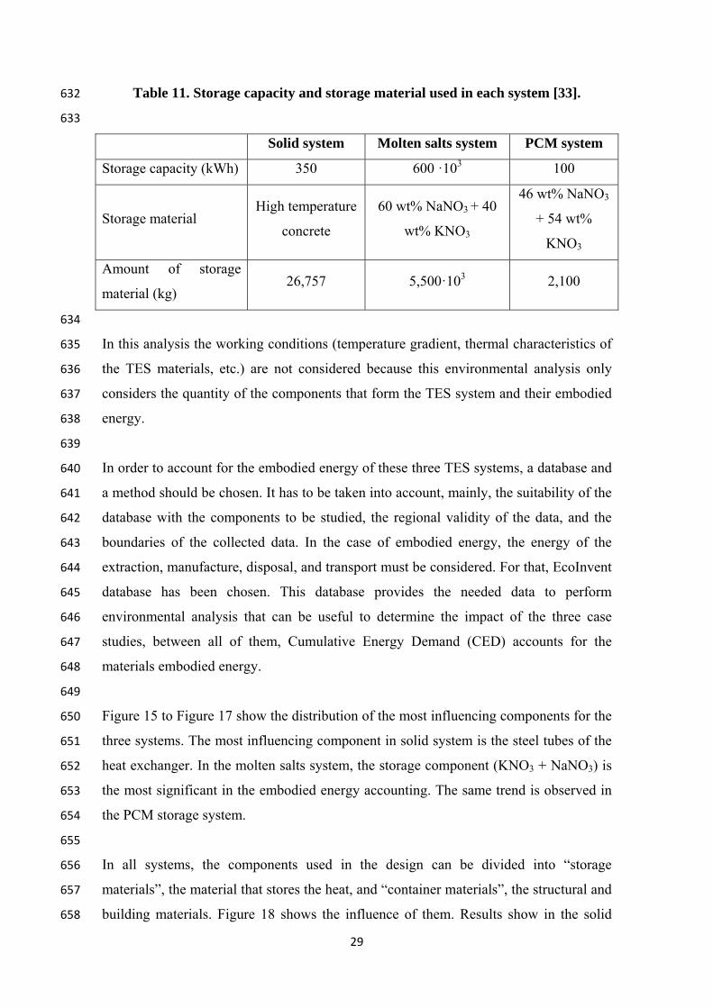
Table 11. Storage capacity and storage material used in each system [33]. 632
633
Solid system Molten salts system PCM system
Storage capacity (kWh) 350 600 ·103 100
Storage material High temperature
concrete
60 wt% NaNO3 + 40
wt% KNO3
46 wt% NaNO3
+ 54 wt%
KNO3
Amount of storage
material (kg) 26,757 5,500·103 2,100
634
In this analysis the working conditions (temperature gradient, thermal characteristics of 635
the TES materials, etc.) are not considered because this environmental analysis only 636
considers the quantity of the components that form the TES system and their embodied 637
energy. 638
639
In order to account for the embodied energy of these three TES systems, a database and 640
a method should be chosen. It has to be taken into account, mainly, the suitability of the 641
database with the components to be studied, the regional validity of the data, and the 642
boundaries of the collected data. In the case of embodied energy, the energy of the 643
extraction, manufacture, disposal, and transport must be considered. For that, EcoInvent 644
database has been chosen. This database provides the needed data to perform 645
environmental analysis that can be useful to determine the impact of the three case 646
studies, between all of them, Cumulative Energy Demand (CED) accounts for the 647
materials embodied energy. 648
649
Figure 15 to Figure 17 show the distribution of the most influencing components for the 650
three systems. The most influencing component in solid system is the steel tubes of the 651
heat exchanger. In the molten salts system, the storage component (KNO3 + NaNO3) is 652
the most significant in the embodied energy accounting. The same trend is observed in 653
the PCM storage system. 654
655
In all systems, the components used in the design can be divided into “storage 656
materials”, the material that stores the heat, and “container materials”, the structural and 657
building materials. Figure 18 shows the influence of them. Results show in the solid 658

6
6
6
6
6
6
6
6
6
6
6
6
syste661
(arou662
662
663
Figu665
666
666
667
Figu670
mo671
672
671
em, the sto
und 30 %). I
ure 15. Dist
ure 16. Dist
olten salts s
orage mater
In the molte
ribution of
ribution of
system (“O
tha
rial contrib
en salts syst
f the embod
soli
f the embod
Other < 5 %
n 5 % in th
30
bution to to
tems it is 70
died energy
id system [
died energy
%” includes
he total dist
otal embod
0 % and 85%
y most influ
33].
y most influ
s all the com
tribution) [
died energy
% in the PC
uencing com
uencing com
mponents th
[33].
y are the lo
CM system.
mponents o
mponents o
hat affect l
owest
of the
of the
less

6
6
6
6
6
6
6
6
6
6
6
6
6
6
6
6
672
Figu675
PCM676
677
676
677
Fig679
680
680
The 687
unde688
asses689
meth690
adva691
comp692
avail693
ure 17. Dist
M system (“
gure 18. Inf
major adv
erstandable
ssment of ch
hod, meanin
antage repre
ponent is d
lable.
ribution of
“Other < 5
fluence of s
vantage of
first envir
hanges of th
ng that it can
esents also
different d
f the embod
%” includ
in the tot
storage mat
thre
applying t
ronmental
he system in
n be applie
a big dra
epending o
31
died energy
des all the c
tal distribu
terials and
ee systems
this metho
screening
n terms of e
d to system
awback bec
on the regi
y most influ
component
tion) [33].
container
[33].
d is that
of the sys
energy savin
ms around th
cause the e
ion, and, t
uencing com
s that affec
embodied
it represen
stem. Also
ngs. Moreov
he world. H
energy nee
this data n
mponents o
ct less than
energy for
nts an easy
o, it allow
ver, it is a g
However, thi
eded to pro
nowadays i
of the
5 %
the
y and
s the
global
is last
oduce
s not

32
4 Discussion687
688
A summary of the operational CO2 mitigation potential of the case studies presented in 689
this paper is presented in Table 12. When the mitigation potential is due to electricity 690
savings, this potential would be very much influenced by the emissions factor, which 691
varies from country to country and from year to year due to the change of the energy 692
mix. Because of this, translating from electricity savings to CO2 emissions savings is 693
not possible and is not presented in this paper. 694
695
Moreover, due to the different reasons for mitigation, a quantitative comparison 696
between the different case studies presented can only be done for each country and not 697
in a general way as it would have been desirable in this paper. 698
699
Embodied CO2 accounting in thermal energy storage has been done only for building 700
materials and for a given case in solar power plants. If the building material is 701
considered as TES material (due to the thermal inertia that can be given by that 702
material), then aluminium and insulation materials are found as the material with higher 703
embodied energy per unit mass, but since buildings usually have much more concrete 704
than any other materials, concrete is the material introducing higher embodied CO2 in 705
most of today’s buildings. Finally, different materials give different energy use during 706
their lifetime when included in a building. This evaluation helps to account the lifetime 707
energy of materials used in buildings. 708
709
On the other hand, embodied CO2 accounting in solar power plants shown in this paper 710
shows that this method can be used to decide where efforts need to be directed to 711
decrease embodied CO2 in a storage system (or any other energy system). Most 712
researchers direct the efforts only to the storage material, while more CO2 can be 713
embedded in the container materials or other system components. 714
715
716

33
Table 12. Summary of CO2 mitigation potential. 717
Application CO2 mitigation potential due
to integrated TES
Main reason for
mitigation
Refrigeration 25-125 [kg/MWh cold
produced]
Electricity savings
Power plant with CSP 800-2000 [kg/MWh electricity
produced]
Larger solar share
Heat on Wheels –
industrial surplus heat
for industrial drying in
Germany
145 [kg/MWh heat delivered] Replacing natural gas for
industrial drying process
Heat on Wheels – CHP
heat replacing local
boilers in Sweden
300-500 [kg/MWh heat
delivered]
Generating more biomass
electricity in CHP plant,
and replacing oil in local
boilers
Indoor climate control
of buildings – passive
integration of TES
1-5 [kg/m2-year] Lowering energy demand
for indoor comfort control
(heating/cooling)
Active climate control
of Supermarket in
Turkey – Heat Pump +
ATES
950 [kg/kWh consumed] Saving electricity due to
higher COP of Heat Pump
Closed Greenhouse
with ATES (Turkey)
8 [kg/ MWh produced ] Electricity savings for
heating
Dishwasher with
zeolite
500 [kg/ dishwasher-year] Lowering energy
consumption from
appliances
718
719
720
721
722

34
5 Conclusions723
724
Thermal energy storage is one of the technologies with potential to reduce the GHG 725
emissions as being part of technologies such as energy supply, buildings, and industry. 726
727
The CO2 mitigation potential of real case studies which include thermal energy storage 728
(TES) is assessed. The CO2 mitigation potential is analysed by calculating the 729
operational CO2, which is the CO2 mitigated during the operation phase of the 730
component/application and the embodied CO2, which is the CO2 released to the ambient 731
while the component/application is made. 732
733
When performing these types of environmental analysis it is important to keep in mind 734
that they depend on the energy mix of the country and on the CO2 emission factor. It 735
should be highlighted that due to the low precision of the eco-attributes related to 736
energy and carbon footprint, it is accepted that there is an uncertainty of about 10 - 20% 737
for decision making. 738
739
The applications with TES presented in this article belong to the work performed in the 740
group Annex 25 “Surplus heat management using advanced TES for CO2 mitigation” of 741
the Energy Conservation through Energy Storage Implementing Agreement (ECES IA) 742
of the International Energy Agency (IEA). 743
744
In this paper a variety of technologies has been assessed in terms of the energy savings, 745
and resulting CO2 mitigation potential from integrating TES. Results are difficult to 746
compare since TES is always designed in relation to its application, and each 747
technology impacts the energy system as a whole to different extents. The applications 748
analysed are refrigeration, solar power plants, mobile heat storage in industrial waste 749
heat recovery, passive systems in buildings, ATES for a supermarket, greenhouse 750
applications, and dishwasher with zeolite in Germany. The paper shows that the reason 751
for mitigation is different in each application, from energy savings to larger solar share 752
or lowering energy consumption from appliances. The mitigation potential dues to 753
integrated TES is quantified in kg/MWh energy produced or heat delivered. 754
755

35
Finally, embodied CO2 in two TES case studies is presented, buildings and solar power 756
plants. It includes the embodied energy involved in the extraction, primary production, 757
transformation, transport to its place of use and recycling. Similarly to operational CO2, 758
to translate the embodied energy into embodied CO2 in any application, the energy mix 759
factor should be used. 760
761
762
Acknowledgements 763
764
The work was partially funded by the Spanish government (project ENE2011-22722 765
and ENE2011-28269-C03-02). The authors would also like to thank the Catalan 766
Government for the quality accreditation given to their research group GREA (2014 767
SGR 123) and DIOPMA (2014 SGR 1543). Laia Miró would like to thank the Spanish 768
Government for her research fellowship (BES-2012-051861). The research leading to 769
these results has received funding from the European Union's Seventh Framework 770
Programme (FP7/2007-2013) under grant agreement n° PIRSES-GA-2013-610692 771
(INNOSTORAGE). The work of ZAE Bayern in the development of the mobile 772
sorption heat storage was supported by the German Federal Ministry of Economics and 773
Technology under the project code 0327383B. ZAE Bayern thanks the Bosch-Siemens-774
Hausgeräte GmbH for the fruitful collaboration in the development of a sorption storage 775
for dishwashers. 776
777
778
References 779
780
1. IPCC, 2007: Climate Change 2007: Synthesis Report. Contribution of Working 781
Groups l, ll and lll to the Fourth Assessment Report of the Intergovernmental Panel 782
on Climate Change [Core Writing Team, Pachauri, R.K and Reisinger, A (eds.)]. 783
IPCC, Geneva, Switzerland, 104 pp. 784
2. Arce P, Medrano M, Gil A, Oró E, Cabeza LF. Overview of thermal energy 785
storage (TES) potential energy savings and climate change mitigation in Spain and 786
Europe. Appl Energ 2011;88:2764-2774. 787
3. Ashby MF. Materials and the environment eco-informed material choice. 2nd ed. 788
St. Louis, MO. Butterworth-Heinemann; 2012. 789

36
4. Advances in thermal energy storage systems. Methods and applications 1st 790
Edition. Editor Cabeza LF. Woodhead Publishing. 2014. 791
5. Oró E, Miró L, Farid MM, Martin V, Cabeza LF. Energy management and CO2 792
mitigation using phase change materials (PCM) for thermal energy storage (TES) in 793
cold storage and transport. Int J Refrigeration 2014;42:26-35. 794
6. Azzouz K, Leducq D, Gobin D. Enhancing the performance of household 795
refrigerators with latent heat storage: An experimental investigation. Int J 796
Refrigeration 2009;32:1634-1644. 797
7. Gin B, Farid MM, Bansal PK. Effect of door opening and defrost cycle on a 798
freezer with phase change panels. Energ Convers Manage 2010;100:372-376. 799
8. Subramaniam P, Tulapurkar C, Thiyagarajan R, Thangamani G. Phase change 800
materials for domestic refrigerators to improve food quality and prolong compressor 801
off time. International Refrigeration and Air Conditioning Conference, Richmond 802
(USA), 2010. 803
9. Ahmed M, Meade O, Medina MA. Reducing heat transfer across the insulated 804
walls of refrigerated truck trailers by the application of phase change materials. 805
Energ Convers Manage 2010;51:383-392. 806
10. Liu M, Saman W, Bruno F. Development of a novel refrigeration system for 807
refrigerated trucks incorporating phase change material. Appl Energ 2012;92:336-808
342. 809
11. Cheralathan M, Velraj R, Renganarayanan S. Performance analysis on industrial 810
refrigeration system integrated with encapsulated PCM-base cool thermal energy 811
storage system. Int J Energ Res 2007;31:1398-1413. 812
12. Wang F, Maidment G, Missenden J, Tozer R. The novel use of phase change 813
materials in refrigeration plant. Part 3: PCM for control and energy savings. Appl 814
Therm Engineering 2007;27:2893-2901. 815
816
13. Powell KM, Edgar TF. Modeling and control of a solar thermal power plant with 817
thermal energy storage. Chem Eng Sci 2012; 71:138-145. 818
14. IPCC 2006, 2006 IPCC Guidelines for National Greenhouse Gas Inventories, 819
Prepared by the National Greenhouse Gas Inventories Programme, Eggleston H.S., 820
Buendia L., Miwa K., Ngara T. and Tanabe K. (eds). Published: IGES, Japan. 821
15. Annex 25 – ECES IA – IEA. Surplus Heat Management using. Advanced TES 822
for CO2 mitigation. Final report. 2014. 823
37
16. Castell A, Martorell I, Medrano M, Pérez G, Cabeza LF. Experimental study of 824
using PCM in brick constructive solutions for passive cooling. Energ Buildings 825
2010;42:534-540. 826
17. De Gracia A, Navarro L, Castell A, Ruiz-Pardo A, Alvarez S, Cabeza LF. 827
Thermal analysis of a ventilated facade with PCM for cooling applications. Energ 828
Buildings 2013;65:508-515. 829
18. Zhu X, Behzadi S, Farid MM, Chen JJJ. The effectiveness of phase change 830
materials for building application in different climates. In press. 831
19. CO2 emissions from fuel combustion. Highlights. IEA Statistics. 2012 edition. 832
20. Paksoy H, Evliya H, Abaci Ş, Mazman M, Konuklu Y, TurgutB, Gök O, Yilmaz 833
M, Yilmaz S, Beyhan B. CO2 Mitigation With Thermal Energy Storage. Int J Global 834
Warming 2009;1:253-269. 835
21. Konuklu Y, Paksoy HÖ. 2009. Phase Change Material Sandwich Panels for 836
Managing Solar Gain in Buildings. J Sol Energy Eng 2009;131: 0410121-0410127. 837
22. Paksoy HÖ, Gürbüz Z, Turgut B, Dikici D, Evliya H. 2004. Aquifer Thermal 838
Storage (ATES) for air-conditioning of a supermarket in Turkey. Renew Energ 839
2004;29:1991-1996. 840
23. Turgut B, Paksoy H, Bozdag S, Evliya H, Abak K, Dasgan HY. (2008). Aquifer 841
Thermal Energy Storage Application in Greenhouse Climatization, World 842
Renewable Energy Congress, July 19-25, Glasgow. 843
24. Vadiee A, Martin V. 2013, “Solar Blind System- Solar Energy Utilization and 844
Climate Mitigation in Glassed Buildings”, accepted for publication in Energy 845
Proceedia, as part of ISES Solar World Congress, Cancun, 2013. 846
25. Vadiee A, Martin V. 2013, “Energy management strategies for commercial 847
greenhouses”, Appl Energ 2014;114:880-888. 848
26. Hauer A, Fischer F. Open Adsorption System for an Energy Efficient 849
Dishwasher. Chem Ing Tech 2011;83:1-7. 850
27. BOSCH AND SIEMENS HOME APPLIANCES GROUP http://www.bsh‐851
group.com/index.php?page=137733 852
28. Santori G, Frazzica A, Freni A, Galieni M, Bonaccorsi L, Polornara F, Restuccia 853
G. Optimization and testing on an adsorption dishwasher. Energy 50 (2013) 170-854
176. 855

38
29. Cabeza LF, Barreneche C, Miró L, Martínez M, Fernández AI, Urge-Vorsatz D. 856
Affordable construction towards sustainable buildings: Review on embodied energy 857
in building materials. Curr Opin in Environ Sustainability 2013;5:229-236. 858
30. CES Selector 2012 software, Granta Design Limited, Cambridge, UK, 2012, 859
www.grantadesign.com [accessed 4 August 2014] 860
31. Jiao Y, Lloyd CR, Wakes SJ. The relationship between total embodied energy 861
and cost of commercial buildings. Energ Buildings 2012;52:20-27. 862
32. Clements A, Shercliff H. Thermal Performance of Laminated Materials for 863
Buildings, J. Materials Education Symposium Cambridge University, April 5th 864
2013. 865
33. Miró L, Oró E, Boer D, Cabeza LF. Embodied energy in thermal energy storage 866
(TES) systems for high temperature applications. Appl Energ 2014, in press. 867
868