MultiCam 1000 Series Waterjet - CNC Cutting Machines for ...
CNC872 Series CNC System Application for Cutting Machines
A List of Basic System Features
Hardware Motherboard with a multi-core processor. Control panel with buttons and LCD touch screen. MCAN unit for two CAN-BUSes connecting drives and peripherals supporting the CanOpen standard. Ethernet, USB, COM, and other connections. Optional SU05 unit controlling analogue and/or pulse drives and reading incremental sensors.
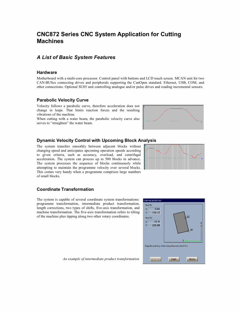
Parabolic Velocity Curve Velocity follows a parabolic curve, therefore acceleration does not change in leaps. That limits reaction forces and the resulting vibrations of the machine. When cutting with a water beam, the parabolic velocity curve also serves to “straighten” the water beam.
Dynamic Velocity Control with Upcoming Block Analysis The system transfers smoothly between adjacent blocks without changing speed and anticipates upcoming operation speeds according to given criteria, such as accuracy, overload, and centrifugal acceleration. The system can process up to 500 blocks in advance. The system processes the sequence of blocks continuously while attempting to maintain the programme velocity over several blocks. This comes very handy when a programme comprises large numbers of small blocks.
Coordinate Transformation The system is capable of several coordinate system transformations: programme transformation, intermediate product transformation, length corrections, two types of shifts, five-axis transformation, and machine transformation. The five-axis transformation refers to tilting of the machine plus tipping along two other rotary coordinates.
An example of intermediate product transformation

Programming Programming can be done in ISO or ESI, with the option of using sub-programmes, macro-cycles, fixed cycle and default shapes. Programming can utilise programme transformation to mirror a shape, shit, turn or scale it up or down. Shapes can also be replicated.
Default Shapes The system contains a set of default shapes. When using any of them, mirroring, shifts, turning or scaling can be requested directly. Default shapes can also be replicated. The operator can set the beginning point of a default shape. Entry and exit parameters are taken from a cutting table for the given material. Shape parameters can be stored as pre-sets. Default shapes selection is open and can be expanded by user-defined shapes or modified default shapes. Creation of shapes utilises the HTML code similar to development of web pages.
PLC Specifications for Cutting Machines
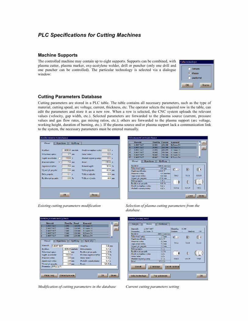
Machine Supports The controlled machine may contain up to eight supports. Supports can be combined, with plasma cutter, plasma marker, oxy-acetylene welder, drill or puncher (only one drill and one puncher can be controlled). The particular technology is selected via a dialogue window:
Cutting Parameters Database Cutting parameters are stored in a PLC table. The table contains all necessary parameters, such as the type of material, cutting speed, arc voltage, current, thickness, etc. The operator selects the required row in the table, can edit the parameters and store it as a new row. When a row is selected, the CNC system uploads the relevant values (velocity, gap width, etc.). Selected parameters are forwarded to the plasma source (current, pressure values and gas flow rates, gas mixing ratios, etc.); others are forwarded to the plasma support (arc voltage, working height, duration of burning, etc.). If the plasma source and/or plasma support lack a communication link to the system, the necessary parameters must be entered manually.
Existing cutting parameters modification Selection of plasma cutting parameters from the
database
Modification of cutting parameters in the database Current cutting parameters setting
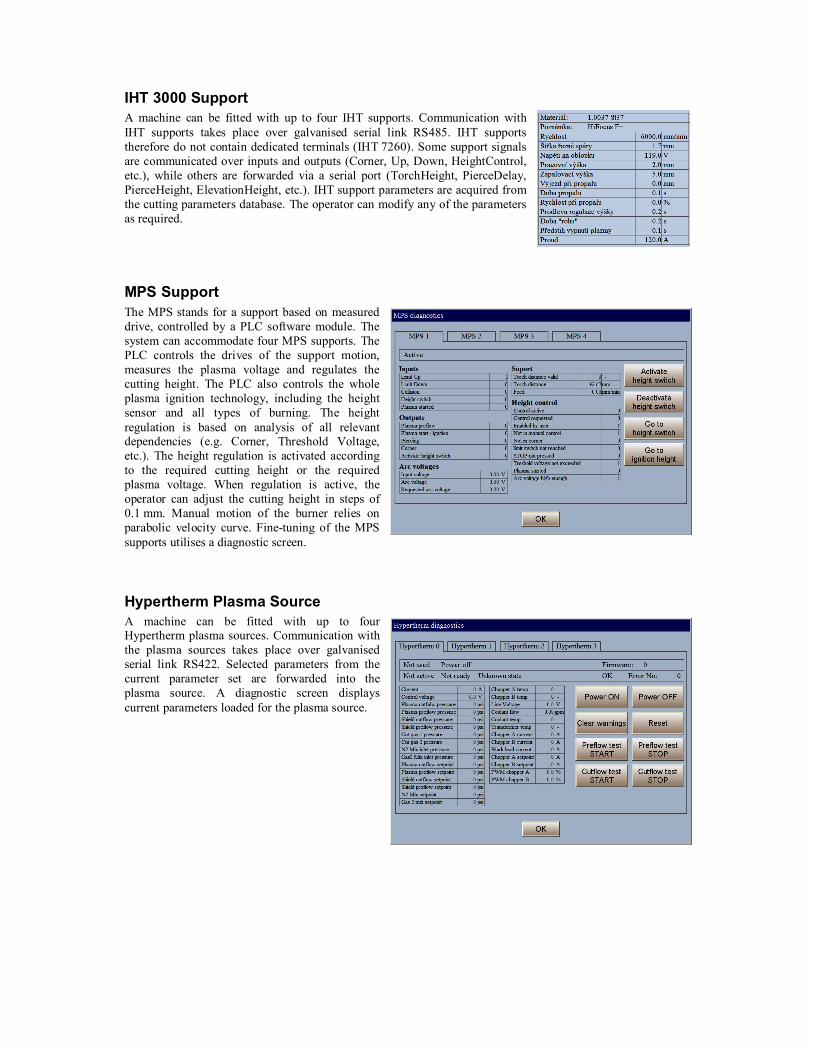
IHT 3000 Support A machine can be fitted with up to four IHT supports. Communication with IHT supports takes place over galvanised serial link RS485. IHT supports therefore do not contain dedicated terminals (IHT 7260). Some support signals are communicated over inputs and outputs (Corner, Up, Down, HeightControl, etc.), while others are forwarded via a serial port (TorchHeight, PierceDelay, PierceHeight, ElevationHeight, etc.). IHT support parameters are acquired from the cutting parameters database. The operator can modify any of the parameters as required.
MPS Support The MPS stands for a support based on measured drive, controlled by a PLC software module. The system can accommodate four MPS supports. The PLC controls the drives of the support motion, measures the plasma voltage and regulates the cutting height. The PLC also controls the whole plasma ignition technology, including the height sensor and all types of burning. The height regulation is based on analysis of all relevant dependencies (e.g. Corner, Threshold Voltage, etc.). The height regulation is activated according to the required cutting height or the required plasma voltage. When regulation is active, the operator can adjust the cutting height in steps of 0.1 mm. Manual motion of the burner relies on parabolic velocity curve. Fine-tuning of the MPS supports utilises a diagnostic screen.
Hypertherm Plasma Source A machine can be fitted with up to four Hypertherm plasma sources. Communication with the plasma sources takes place over galvanised serial link RS422. Selected parameters from the current parameter set are forwarded into the plasma source. A diagnostic screen displays current parameters loaded for the plasma source.

Kjellberg Plasma Source A machine can be fitted with up to four Kjellberg plasma sources. Communication with the plasma sources takes place over galvanised serial link RS485. Selected parameters from the current parameter set are forwarded into the plasma source. A diagnostic screen displays current parameters loaded for the plasma source.
Generic Plasma Source A generic plasma source does not contain a serial link to the system (e.g. Cebora). The operator must enter the desired parameters from the table manually.
Oxy-acetylene Welder The system can control various oxy-acetylene welder supports. The welder burner can be mounted separately or in combination with a plasma burner. The PLC can control the technological process in combination with automatic or manual gas console. The support height and movement regulation can operate autonomously or be controlled by the PLC module.
Cutting on a Tube The system allows for controlling a machine cutting on a tube. Cutting on a tube utilises machine transformation, without affecting the burning programme. The operator enters the tube diameter in the dialogue window shown on the right.
Drill A machine may contain one drill. The drill is controlled autonomously and the drilling depth is set by stoppers. The machine support can be combined and contain several devices (oxy-acetylene welder, plasma cutter, plasma marker, puncher, drill). In such a scenario, accurate distances between the adjacent technologies on the support must be entered. The processing plan then contains a selection of technologies, but does not contain measurements corresponding to the relevant device shifts.
Puncher A machine can be fitted with a text puncher. Communication with the puncher takes place via a serial link RS232. The text to be punched is entered directly in the burning programme.
High-pressure Water Beam A PLC variant is used to control machines with a high-pressure water beam to:
• control the high-pressure analogue or dual-mode pump; • control abrasive dosage; • straighten the beam in corners when cutting thick materials through selection of suitable parabolic
ramps parameters; • automatically set all technological qualities according to the cutting parameters database.
Future Outlook Further improvements are under development, such as:
• Cutting of non-round profiles with programming based on unfolding. • Burner tilting. Determination of the cutting angle at any point. • Combination of high-pressure water beam with plasma and oxy-acetylene burners.
Language Versions • Czech • English • German • Polish