Cnc Usb Controller
153
CNC USB Controller User manual 2012-12-15 1
-
Upload
valentin-banica -
Category
Documents
-
view
346 -
download
11
Transcript of Cnc Usb Controller
CNC USB Controller
User manual
2012-12-15
1
Disclaimer
CONTROLLER AND CONTROLLER SOFTWARE ARE PROVIDED TO YOU "AS IS," WITHOUT WARRANTY. THERE IS NO WARRANTY FOR THE CONTROLLER AND CONTROLLER SOFTWARE, EITHER EXPRESSED OR IMPLIED, INCLUDING, BUT NOT LIMITED TO, THE IMPLIED WARRANTIES OF MERCHANTABILITY AND FITNESS FOR A PARTICULAR PURPOSE AND NONINFRINGEMENT OF THIRD PARTY RIGHTS. THE ENTIRE RISK AS TO THE QUALITY AND PERFORMANCE OF THE CONTROLLER OR CONTROLLER SOFTWARE IS WITH YOU. SHOULD THE CONTROLLER OR CONTROLLER SOFTWARE PROVE DEFECTIVE, YOU ASSUME THE COST OF ALL NECESSARY SERVICING, REPAIR OR CORRECTION.IN NO EVENT SHALL THE AUTHOR BE LIABLE TO YOU FOR DAMAGES, INCLUDINGANY GENERAL, SPECIAL, INCIDENTAL OR CONSEQUENTIAL DAMAGES ARISING OUTOF THE USE OR INABILITY TO USE THE CONTROLLER OR CONTROLLER SOFTWARE.
2
1 Introduction
1.1 Overview
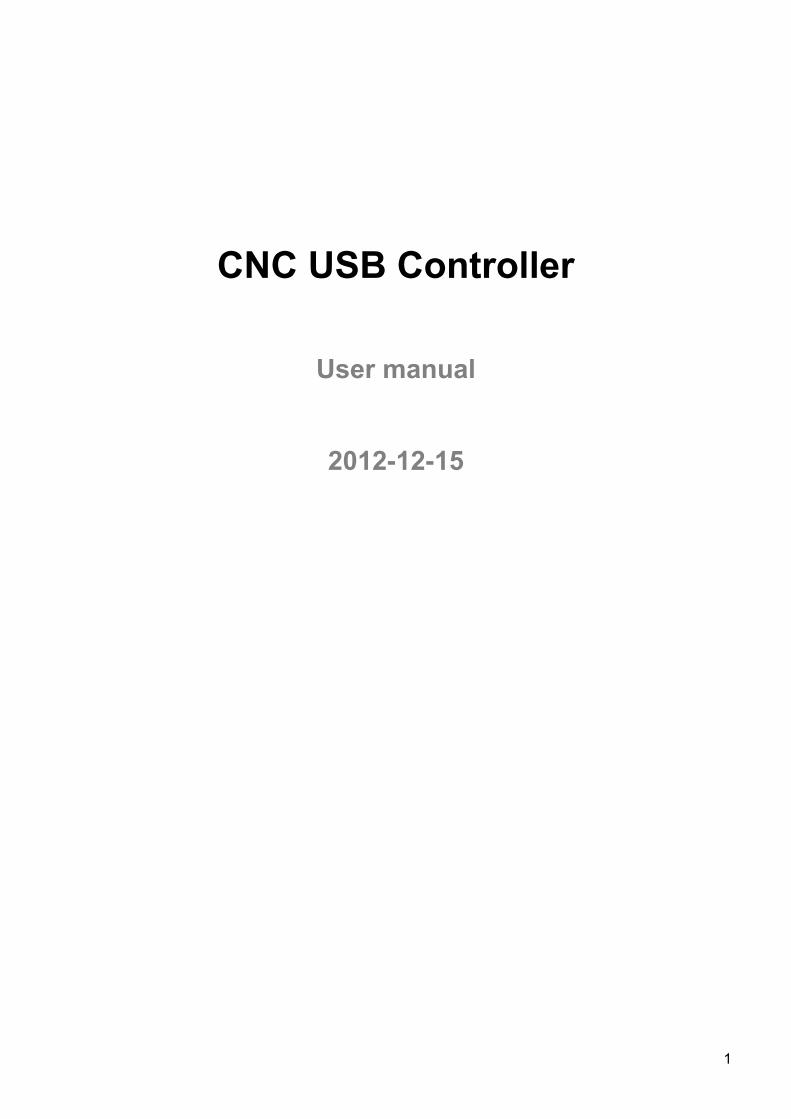
The planet-cnc.com series of USB CNC motion controllers link between a personal computer and motor drivers supporting step/dir control. They are compatible with most drivers. The controllers use the USB port, available on all modern computers and laptops. They can serve as direct replacement or upgrade for many parallel port break-out boards. There are currently three models available. The Mk1 controller for up to 4 axes, the Mk2 controller, using up to 9 axes and the Mk2/4 controller supporting up to 4 axes. The Mk2/4 controller is essentially a 4 axis version of the Mk2 controller, supporting the same high pulse rate and advanced software functions. It also provides DB25 and built-in screw terminal connections.
PlanetCNC controllers provide a complete, fully integrated software/hardware solution. Additional machine control software is NOT required. The USB CNC Controller software is a dedicated application, designed to fully exploit the features of the purpose-built hardware. It has many advanced features to assist day-to-day CNC machine operation.
3
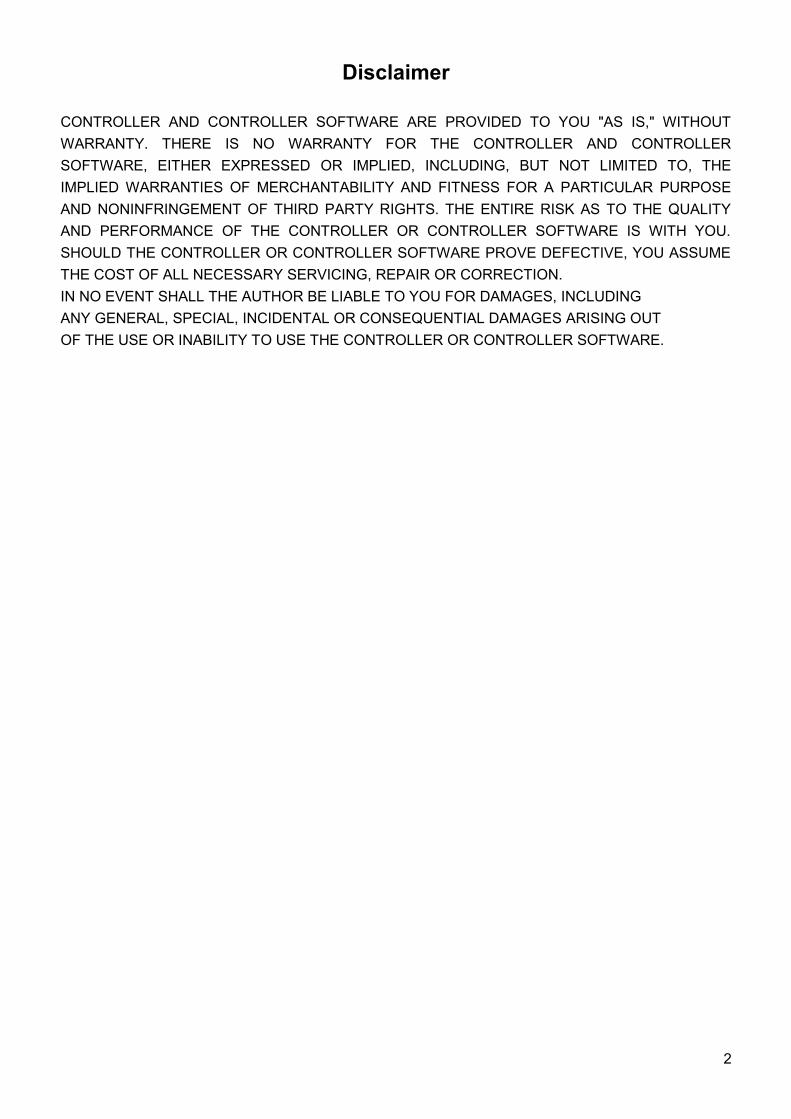
Optional modules that add a range of functions to the USB CNC Controller series can be used.Adapters simplifies connections to motor drivers, output board adds 3 relays and 0-10V for VFD, MPG pendant adapter adds connectivity to MPG pendants, SD card adapter adds support for running programs without PC from SD card.
MPG pendant and SD Card adapters are only supported by the Mk2 9-Axiscontroller.
This approach reduces cost. Users can purchase only the hardware optionsthey need. planet-cnc.com can provide an absolute minimum cost, ‘self-build’ optionof a bare Mk1 controller PCB, with components list and diagrams.
4
1.2 Features and specifications:• USB (V2.x) from PC/Laptop running Windows XP, Vista or Windows 7 (32 bit or 64bit) • motor driver connector pin-out is compatible with 10 pin open source interface • controller works with most step/dir motor drivers available on the market • buffered IO for maximum performance • advanced interpolation algorithms • start, stop, pause and resume execution of program on your machine • standard RS274/NGC G-code (EMC2 compatible) • advanced G-codes - G40, G41, G42 (Cutter Radius Compensation) supported • advanced G-codes - G43, G49 (Tool Length Offsets) supported • advanced G-codes - G54, G59.3 (Coordinate System Origins) supported • tested with SolidCAM, MasterCAM, ArtCAM, Vectric, ... generated G-code • Profili 4-axes and 3-axes G-code supported • import toolpath from DXF files • import toolpath from PLT/HPGL files • import toolpath from image files • import toolpath from NC-Drill (Excellon) files • import toolpath from Gerber (RS-274X) files • toolpath simulation • automatic homing procedure • automatic tool length measuring• advanced toolchange procedures • export toolpath to G-code • export toolpath to DXF • SDK (software developers kit) is available • works on MacOS X (Snow Leopard 10.6.3) with virtual machine emulating Windows XP SP3
5
1.2.1 Mk1 - 4 axes USB CNC controller• 25 kHz maximum step frequency • 3 digital outputs (flood, mist, spindle) • 12 us minimum pulse width • manual jog input keys for all axes • limit keys for all axes • control external devices with I2C protocol
1.2.2 Mk2 - 9 axes USB CNC controller• 100 kHz maximum step frequency • 7 digital outputs • 12 us minimum pulse width • manual jog input keys for all axes • limit keys for all axes • 5 general inputs • 8 control inputs for pendant or similar device • SD card support for running g-code without computer • control external devices with I2C protocol
1.2.3 Mk2/4 - 4 axes USB CNC controller• 100 kHz maximum step frequency • 3 digital outputs • 12 us minimum pulse width • manual jog input keys for all axes • limit keys for all axes (single input mode)• 4 inputs for tool sensor, e-stop, ...
6
1.3 System RequirementsMinimum system requirements:
• 1 GHz or faster processor • 512MB RAM• 500 MB available hard disk space• DirectX 9 graphics device with WDDM 1.0 or higher driver• USB 2.0 port• .NET Framework 3.5 SP1
Recommended system requirements:• 2 GHz or faster processor • 2GB RAM• 500 MB available hard disk space• DirectX 9 graphics device with WDDM 1.0 or higher driver• USB 2.0 port• .NET Framework 3.5 SP1
7
2 Hardware
2.1 Installation
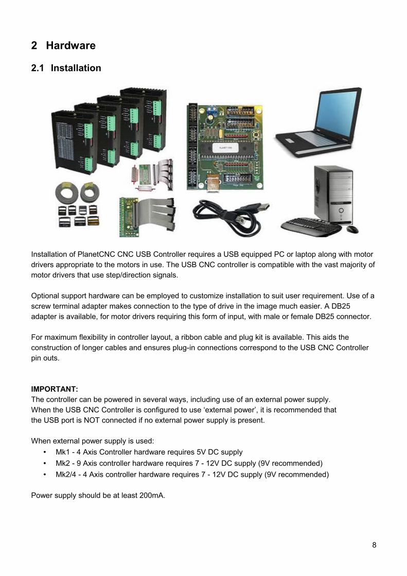
Installation of PlanetCNC CNC USB Controller requires a USB equipped PC or laptop along with motor drivers appropriate to the motors in use. The USB CNC controller is compatible with the vast majority of motor drivers that use step/direction signals.
Optional support hardware can be employed to customize installation to suit user requirement. Use of a screw terminal adapter makes connection to the type of drive in the image much easier. A DB25 adapter is available, for motor drivers requiring this form of input, with male or female DB25 connector.
For maximum flexibility in controller layout, a ribbon cable and plug kit is available. This aids the construction of longer cables and ensures plug-in connections correspond to the USB CNC Controller pin outs.
IMPORTANT:The controller can be powered in several ways, including use of an external power supply.When the USB CNC Controller is configured to use ‘external power’, it is recommended thatthe USB port is NOT connected if no external power supply is present.
When external power supply is used:• Mk1 - 4 Axis Controller hardware requires 5V DC supply• Mk2 - 9 Axis controller hardware requires 7 - 12V DC supply (9V recommended)• Mk2/4 - 4 Axis controller hardware requires 7 - 12V DC supply (9V recommended)
Power supply should be at least 200mA.
8
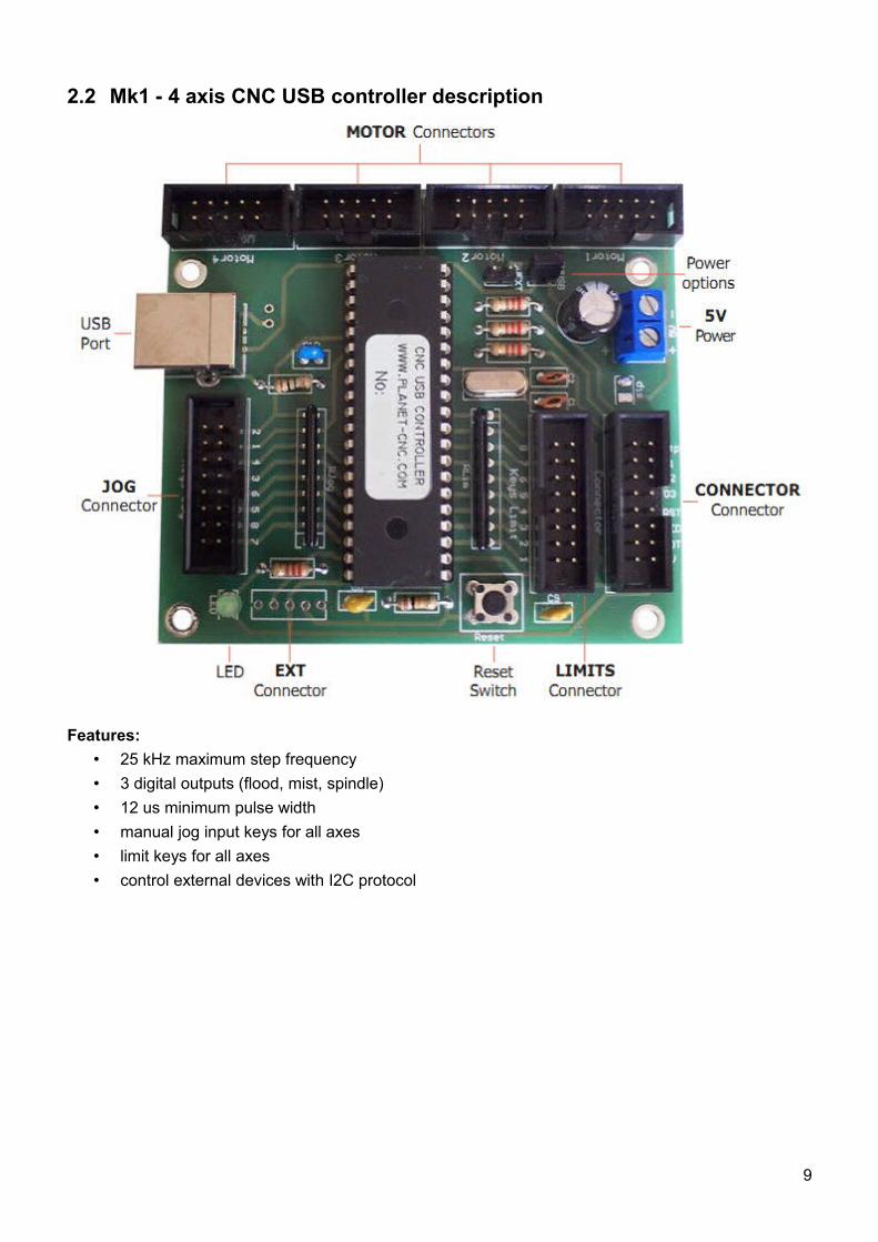
2.2 Mk1 - 4 axis CNC USB controller description
Features:• 25 kHz maximum step frequency • 3 digital outputs (flood, mist, spindle) • 12 us minimum pulse width • manual jog input keys for all axes • limit keys for all axes • control external devices with I2C protocol
9
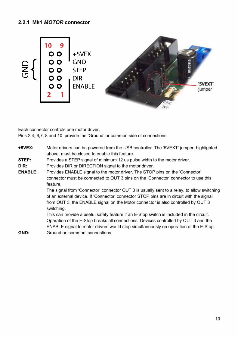
2.2.1 Mk1 MOTOR connector
Each connector controls one motor driver. Pins 2,4, 6,7, 8 and 10 provide the ‘Ground’ or common side of connections.
+5VEX: Motor drivers can be powered from the USB controller. The ‘5VEXT’ jumper, highlighted above, must be closed to enable this feature.
STEP: Provides a STEP signal of minimum 12 us pulse width to the motor driver.DIR: Provides DIR or DIRECTION signal to the motor driver.ENABLE: Provides ENABLE signal to the motor driver. The STOP pins on the ‘Connector’
connector must be connected to OUT 3 pins on the ‘Connector’ connector to use this feature. The signal from ‘Connector’ connector OUT 3 is usually sent to a relay, to allow switching of an external device. If ‘Connector’ connector STOP pins are in circuit with the signal from OUT 3, the ENABLE signal on the Motor connector is also controlled by OUT 3 switching. This can provide a useful safety feature if an E-Stop switch is included in the circuit. Operation of the E-Stop breaks all connections. Devices controlled by OUT 3 and the ENABLE signal to motor drivers would stop simultaneously on operation of the E-Stop.
GND: Ground or ‘common’ connections.
10
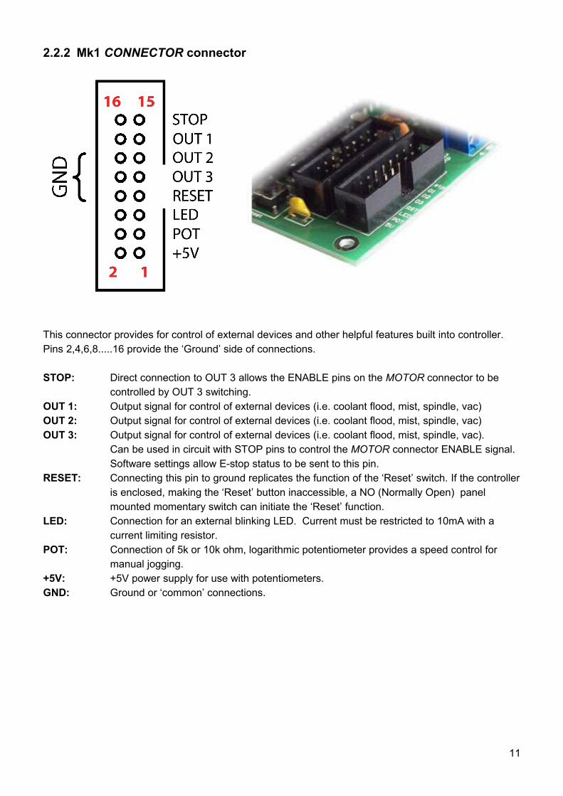
2.2.2 Mk1 CONNECTOR connector
This connector provides for control of external devices and other helpful features built into controller. Pins 2,4,6,8.....16 provide the ‘Ground’ side of connections.
STOP: Direct connection to OUT 3 allows the ENABLE pins on the MOTOR connector to be controlled by OUT 3 switching.
OUT 1: Output signal for control of external devices (i.e. coolant flood, mist, spindle, vac)OUT 2: Output signal for control of external devices (i.e. coolant flood, mist, spindle, vac)OUT 3: Output signal for control of external devices (i.e. coolant flood, mist, spindle, vac).
Can be used in circuit with STOP pins to control the MOTOR connector ENABLE signal.Software settings allow E-stop status to be sent to this pin.
RESET: Connecting this pin to ground replicates the function of the ‘Reset’ switch. If the controller is enclosed, making the ‘Reset’ button inaccessible, a NO (Normally Open) panel mounted momentary switch can initiate the ‘Reset’ function.
LED: Connection for an external blinking LED. Current must be restricted to 10mA with a current limiting resistor.
POT: Connection of 5k or 10k ohm, logarithmic potentiometer provides a speed control for manual jogging.
+5V: +5V power supply for use with potentiometers. GND: Ground or ‘common’ connections.
11
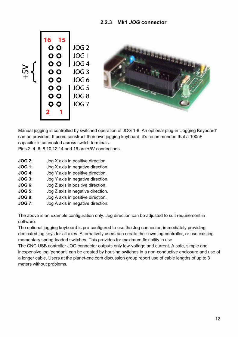
2.2.3 Mk1 JOG connector
Manual jogging is controlled by switched operation of JOG 1-8. An optional plug-in ‘Jogging Keyboard’ can be provided. If users construct their own jogging keyboard, it’s recommended that a 100nF capacitor is connected across switch terminals.Pins 2, 4, 6, 8,10,12,14 and 16 are +5V connections.
JOG 2: Jog X axis in positive direction.JOG 1: Jog X axis in negative direction.JOG 4: Jog Y axis in positive direction.JOG 3: Jog Y axis in negative direction.JOG 6: Jog Z axis in positive direction.JOG 5: Jog Z axis in negative direction.JOG 8: Jog A axis in positive direction.JOG 7: Jog A axis in negative direction.
The above is an example configuration only. Jog direction can be adjusted to suit requirement in software.The optional jogging keyboard is pre-configured to use the Jog connector, immediately providing dedicated jog keys for all axes. Alternatively users can create their own jog controller, or use existing momentary spring-loaded switches. This provides for maximum flexibility in use.The CNC USB controller JOG connector outputs only low-voltage and current. A safe, simple and inexpensive jog ‘pendant’ can be created by housing switches in a non-conductive enclosure and use of a longer cable. Users at the planet-cnc.com discussion group report use of cable lengths of up to 3 meters without problems.
12
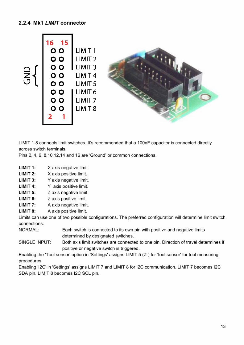
2.2.4 Mk1 LIMIT connector
LIMIT 1-8 connects limit switches. It’s recommended that a 100nF capacitor is connected directly across switch terminals. Pins 2, 4, 6, 8,10,12,14 and 16 are ‘Ground’ or common connections.
LIMIT 1: X axis negative limit.LIMIT 2: X axis positive limit.LIMIT 3: Y axis negative limit.LIMIT 4: Y axis positive limit.LIMIT 5: Z axis negative limit.LIMIT 6: Z axis positive limit.LIMIT 7: A axis negative limit.LIMIT 8: A axis positive limit.Limits can use one of two possible configurations. The preferred configuration will determine limit switch connections.NORMAL: Each switch is connected to its own pin with positive and negative limits
determined by designated switches.SINGLE INPUT: Both axis limit switches are connected to one pin. Direction of travel determines if
positive or negative switch is triggered.Enabling the 'Tool sensor' option in 'Settings' assigns LIMIT 5 (Z-) for 'tool sensor' for tool measuring procedures.Enabling 'I2C' in 'Settings' assigns LIMIT 7 and LIMIT 8 for I2C communication. LIMIT 7 becomes I2C SDA pin, LIMIT 8 becomes I2C SCL pin.
13
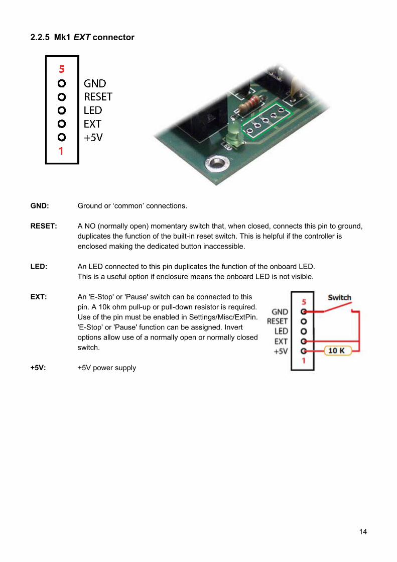
2.2.5 Mk1 EXT connector
GND: Ground or ‘common’ connections.
RESET: A NO (normally open) momentary switch that, when closed, connects this pin to ground, duplicates the function of the built-in reset switch. This is helpful if the controller is enclosed making the dedicated button inaccessible.
LED: An LED connected to this pin duplicates the function of the onboard LED. This is a useful option if enclosure means the onboard LED is not visible.
EXT: An 'E-Stop' or 'Pause' switch can be connected to this pin. A 10k ohm pull-up or pull-down resistor is required. Use of the pin must be enabled in Settings/Misc/ExtPin. 'E-Stop' or 'Pause' function can be assigned. Invert options allow use of a normally open or normally closed switch.
+5V: +5V power supply
14
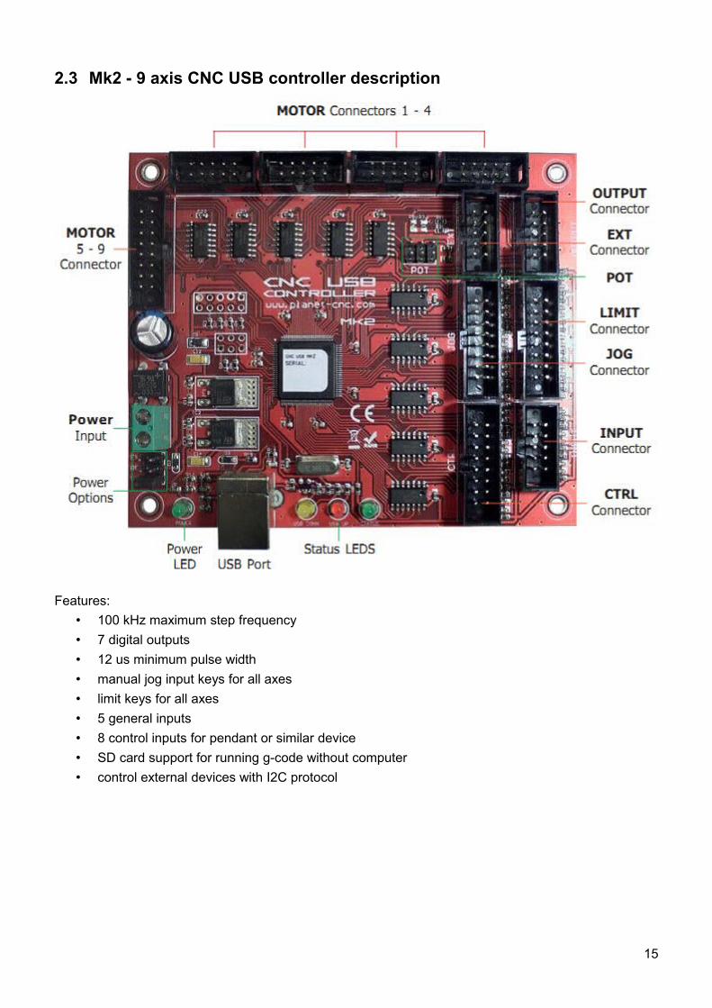
2.3 Mk2 - 9 axis CNC USB controller description
Features:• 100 kHz maximum step frequency • 7 digital outputs • 12 us minimum pulse width • manual jog input keys for all axes • limit keys for all axes • 5 general inputs • 8 control inputs for pendant or similar device • SD card support for running g-code without computer • control external devices with I2C protocol
15
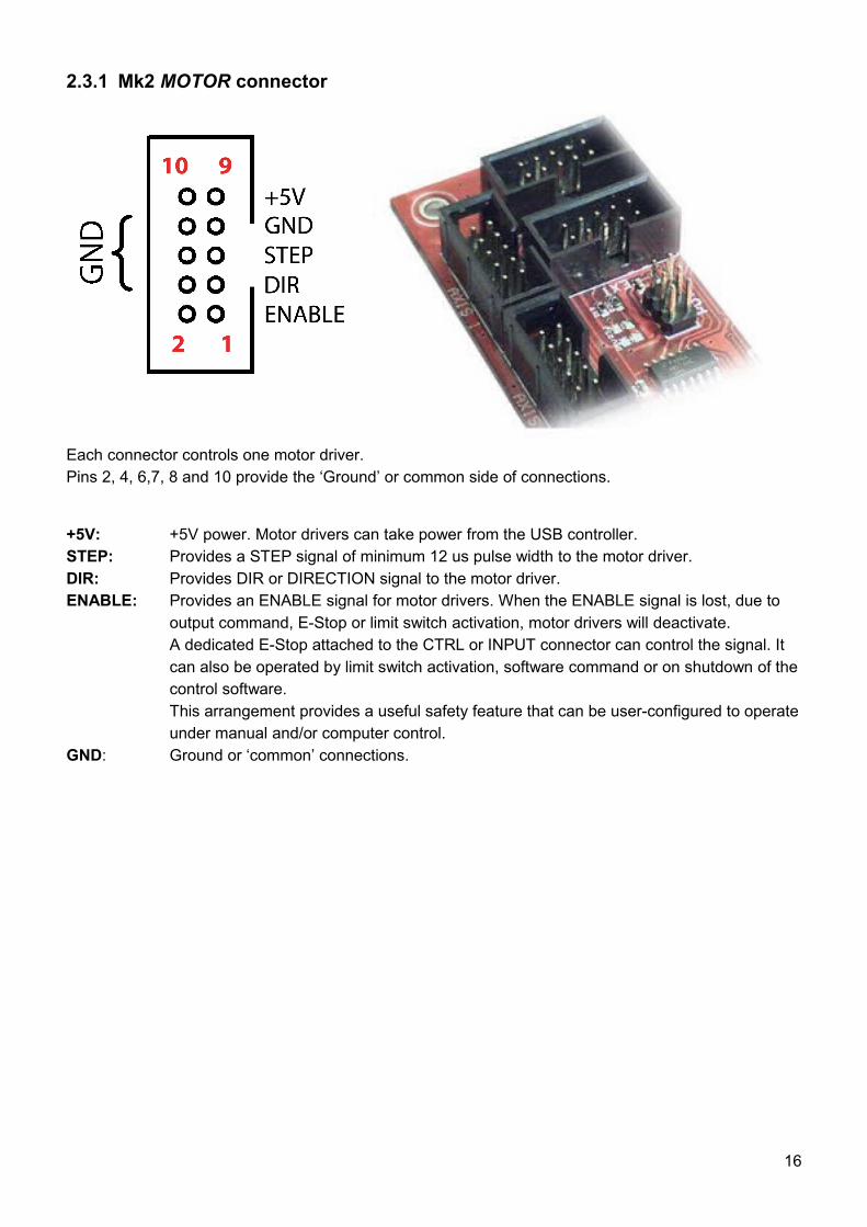
2.3.1 Mk2 MOTOR connector
Each connector controls one motor driver.Pins 2, 4, 6,7, 8 and 10 provide the ‘Ground’ or common side of connections.
+5V: +5V power. Motor drivers can take power from the USB controller.STEP: Provides a STEP signal of minimum 12 us pulse width to the motor driver.DIR: Provides DIR or DIRECTION signal to the motor driver. ENABLE: Provides an ENABLE signal for motor drivers. When the ENABLE signal is lost, due to
output command, E-Stop or limit switch activation, motor drivers will deactivate.A dedicated E-Stop attached to the CTRL or INPUT connector can control the signal. It can also be operated by limit switch activation, software command or on shutdown of the control software.This arrangement provides a useful safety feature that can be user-configured to operate under manual and/or computer control.
GND: Ground or ‘common’ connections.
16
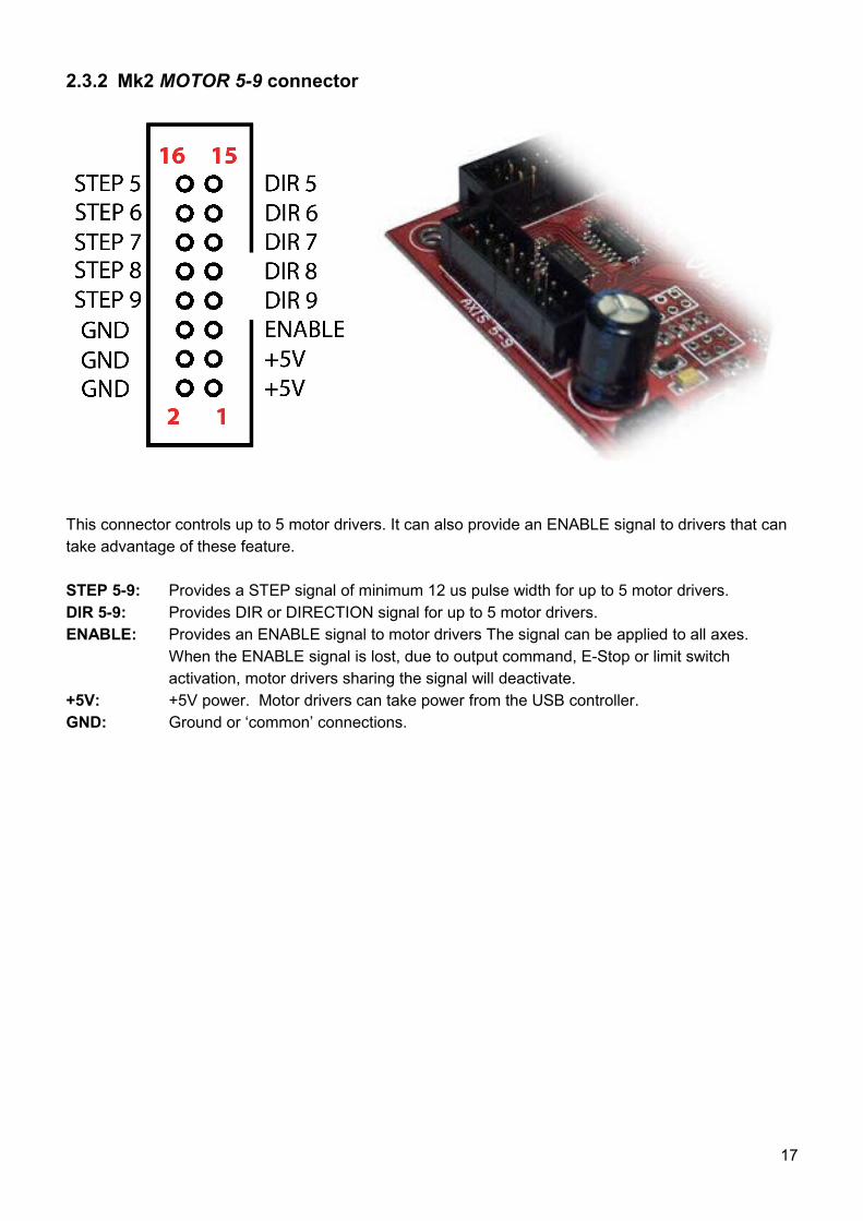
2.3.2 Mk2 MOTOR 5-9 connector
This connector controls up to 5 motor drivers. It can also provide an ENABLE signal to drivers that can take advantage of these feature.
STEP 5-9: Provides a STEP signal of minimum 12 us pulse width for up to 5 motor drivers.DIR 5-9: Provides DIR or DIRECTION signal for up to 5 motor drivers. ENABLE: Provides an ENABLE signal to motor drivers The signal can be applied to all axes.
When the ENABLE signal is lost, due to output command, E-Stop or limit switch activation, motor drivers sharing the signal will deactivate.
+5V: +5V power. Motor drivers can take power from the USB controller.GND: Ground or ‘common’ connections.
17
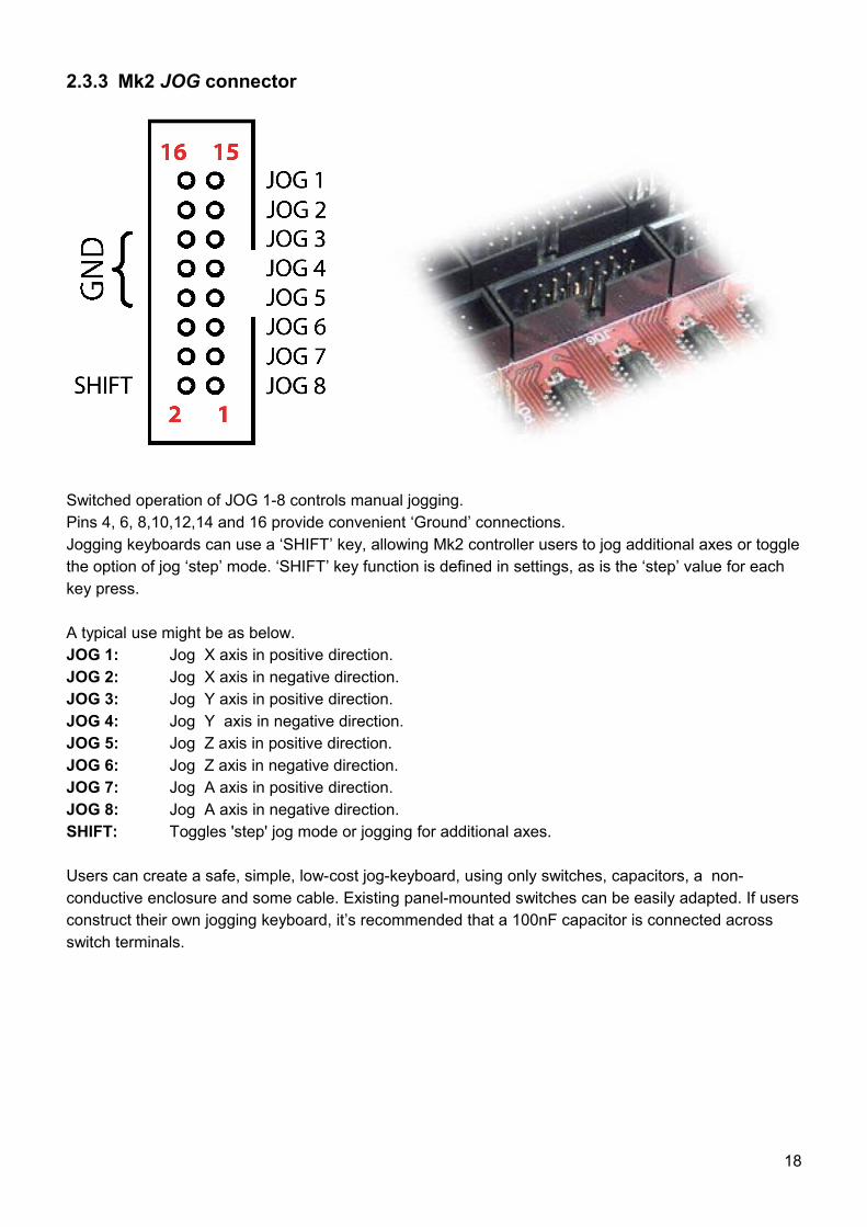
2.3.3 Mk2 JOG connector
Switched operation of JOG 1-8 controls manual jogging. Pins 4, 6, 8,10,12,14 and 16 provide convenient ‘Ground’ connections. Jogging keyboards can use a ‘SHIFT’ key, allowing Mk2 controller users to jog additional axes or toggle the option of jog ‘step’ mode. ‘SHIFT’ key function is defined in settings, as is the ‘step’ value for each key press.
A typical use might be as below.JOG 1: Jog X axis in positive direction.JOG 2: Jog X axis in negative direction.JOG 3: Jog Y axis in positive direction.JOG 4: Jog Y axis in negative direction.JOG 5: Jog Z axis in positive direction.JOG 6: Jog Z axis in negative direction.JOG 7: Jog A axis in positive direction.JOG 8: Jog A axis in negative direction.SHIFT: Toggles 'step' jog mode or jogging for additional axes.
Users can create a safe, simple, low-cost jog-keyboard, using only switches, capacitors, a non-conductive enclosure and some cable. Existing panel-mounted switches can be easily adapted. If users construct their own jogging keyboard, it’s recommended that a 100nF capacitor is connected across switch terminals.
18
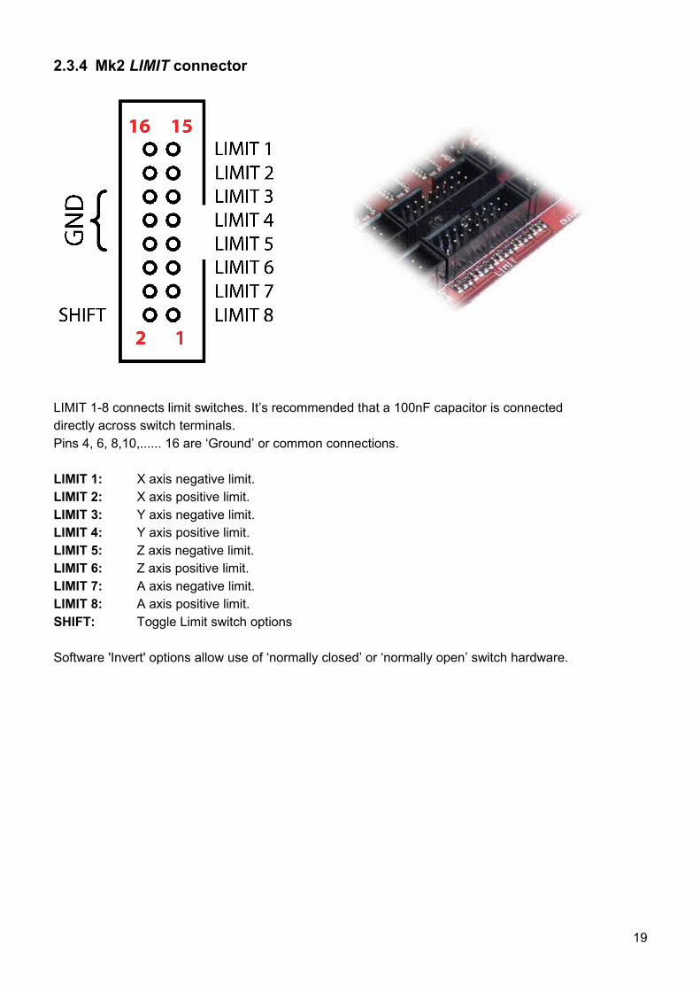
2.3.4 Mk2 LIMIT connector
LIMIT 1-8 connects limit switches. It’s recommended that a 100nF capacitor is connecteddirectly across switch terminals. Pins 4, 6, 8,10,...... 16 are ‘Ground’ or common connections.
LIMIT 1: X axis negative limit.LIMIT 2: X axis positive limit.LIMIT 3: Y axis negative limit.LIMIT 4: Y axis positive limit.LIMIT 5: Z axis negative limit.LIMIT 6: Z axis positive limit.LIMIT 7: A axis negative limit.LIMIT 8: A axis positive limit.SHIFT: Toggle Limit switch options
Software 'Invert' options allow use of ‘normally closed’ or ‘normally open’ switch hardware.
19
The 'SHIFT' key toggles limit options using one of three possible configurations. The chosen configuration determines hardware connections.
NORMAL: Each switch is connected to its own pin.SHIFT OFF: Axes 1 to 4 limits are selectedSHIFT ON: Axes 5 to 9 limits are selected
SINGLE INPUT: Both axis limit switches are connected to one pin. Direction of travel determines if positive or negative switch is triggered.SHIFT ON: Axis 9 selected
SINGLE INPUT/SINGLE INPUT SHIFT:Both axis limit switches are connected to one pin with the ‘SHIFT’ pin used to determine if positive or negative limit is triggered.
20
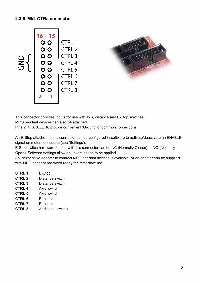
2.3.5 Mk2 CTRL connector
This connector provides inputs for use with axis, distance and E-Stop switches. MPG pendant devices can also be attached. Pins 2, 4, 6, 8.......16 provide convenient ‘Ground’ or common connections.
An E-Stop attached to this connector can be configured in software to activate/deactivate an ENABLE signal on motor connectors (see 'Settings'). E-Stop switch hardware for use with this connector can be NC (Normally Closed) or NO (Normally Open). Software settings allow an ‘Invert ‘option to be applied.An inexpensive adapter to connect MPG pendant devices is available, or an adapter can be supplied with MPG pendant pre-wired ready for immediate use.
CTRL 1: E-StopCTRL 2: Distance switchCTRL 3: Distance switchCTRL 4: Axis switchCTRL 5: Axis switchCTRL 6: EncoderCTRL 7: EncoderCTRL 8: Additional switch
21
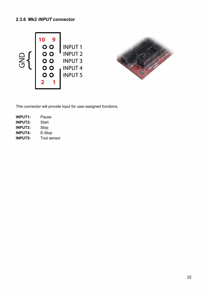
2.3.6 Mk2 INPUT connector
This connector will provide input for user-assigned functions.
INPUT1: PauseINPUT2: StartINPUT3: StopINPUT4: E-StopINPUT5: Tool sensor
22
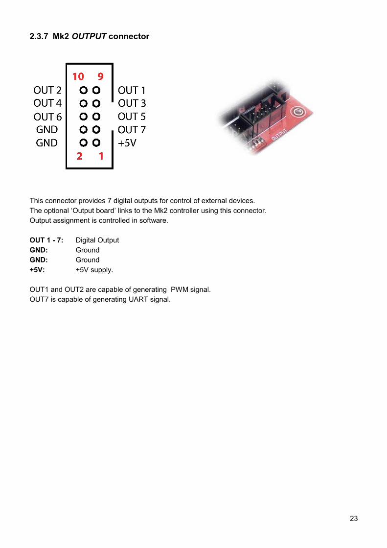
2.3.7 Mk2 OUTPUT connector
This connector provides 7 digital outputs for control of external devices. The optional ‘Output board’ links to the Mk2 controller using this connector. Output assignment is controlled in software.
OUT 1 - 7: Digital OutputGND: GroundGND: Ground+5V: +5V supply.
OUT1 and OUT2 are capable of generating PWM signal.OUT7 is capable of generating UART signal.
23
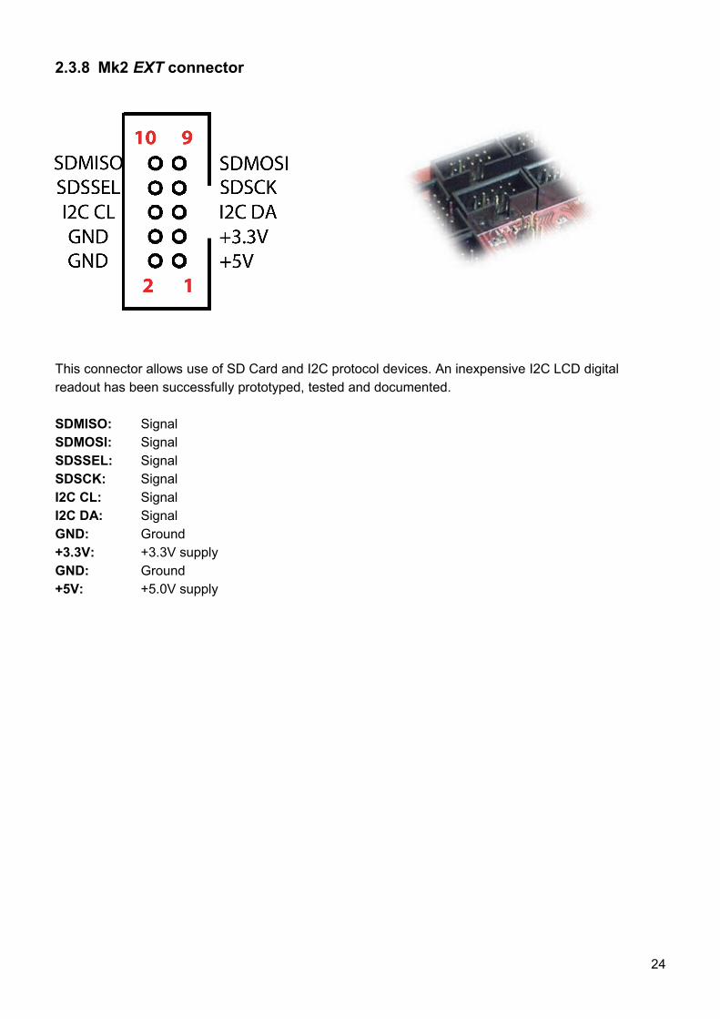
2.3.8 Mk2 EXT connector
This connector allows use of SD Card and I2C protocol devices. An inexpensive I2C LCD digital readout has been successfully prototyped, tested and documented.
SDMISO: SignalSDMOSI: SignalSDSSEL: SignalSDSCK: SignalI2C CL: SignalI2C DA: SignalGND: Ground+3.3V: +3.3V supplyGND: Ground+5V: +5.0V supply
24
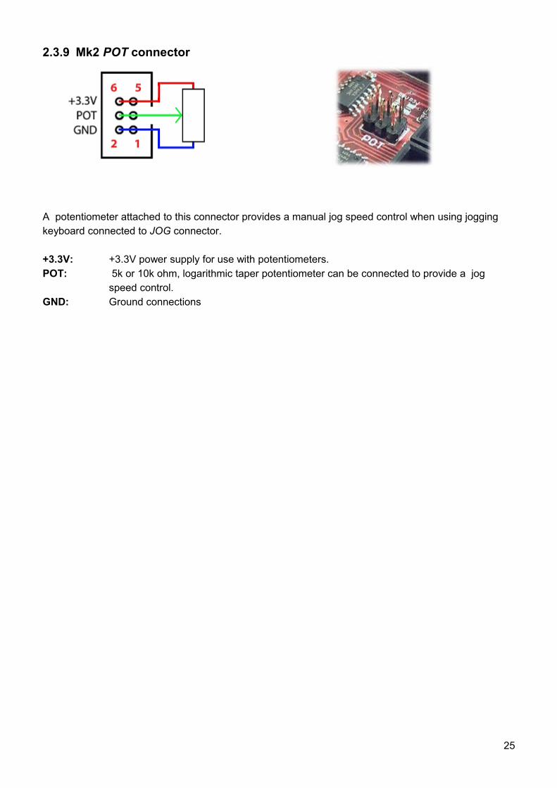
2.3.9 Mk2 POT connector
A potentiometer attached to this connector provides a manual jog speed control when using jogging keyboard connected to JOG connector.
+3.3V: +3.3V power supply for use with potentiometers. POT: 5k or 10k ohm, logarithmic taper potentiometer can be connected to provide a jog
speed control.GND: Ground connections
25
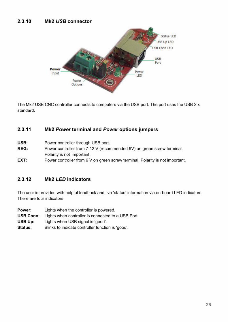
2.3.10 Mk2 USB connector
The Mk2 USB CNC controller connects to computers via the USB port. The port uses the USB 2.x standard.
2.3.11 Mk2 Power terminal and Power options jumpers
USB: Power controller through USB port.REG: Power controller from 7-12 V (recommended 9V) on green screw terminal.
Polarity is not important.EXT: Power controller from 6 V on green screw terminal. Polarity is not important.
2.3.12 Mk2 LED indicators
The user is provided with helpful feedback and live ‘status’ information via on-board LED indicators. There are four indicators.
Power: Lights when the controller is powered.USB Conn: Lights when controller is connected to a USB PortUSB Up: Lights when USB signal is ‘good’.Status: Blinks to indicate controller function is ‘good’.
26
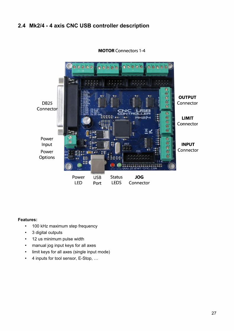
2.4 Mk2/4 - 4 axis CNC USB controller description
Features:• 100 kHz maximum step frequency • 3 digital outputs • 12 us minimum pulse width • manual jog input keys for all axes • limit keys for all axes (single input mode)• 4 inputs for tool sensor, E-Stop, …
27
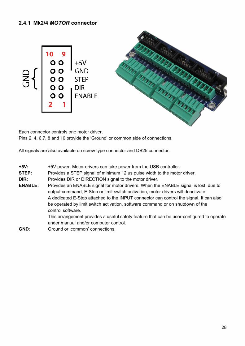
2.4.1 Mk2/4 MOTOR connector
Each connector controls one motor driver.Pins 2, 4, 6,7, 8 and 10 provide the ‘Ground’ or common side of connections.
All signals are also available on screw type connector and DB25 connector.
+5V: +5V power. Motor drivers can take power from the USB controller.STEP: Provides a STEP signal of minimum 12 us pulse width to the motor driver.DIR: Provides DIR or DIRECTION signal to the motor driver. ENABLE: Provides an ENABLE signal for motor drivers. When the ENABLE signal is lost, due to
output command, E-Stop or limit switch activation, motor drivers will deactivate.A dedicated E-Stop attached to the INPUT connector can control the signal. It can also be operated by limit switch activation, software command or on shutdown of the control software.This arrangement provides a useful safety feature that can be user-configured to operate under manual and/or computer control.
GND: Ground or ‘common’ connections.
28
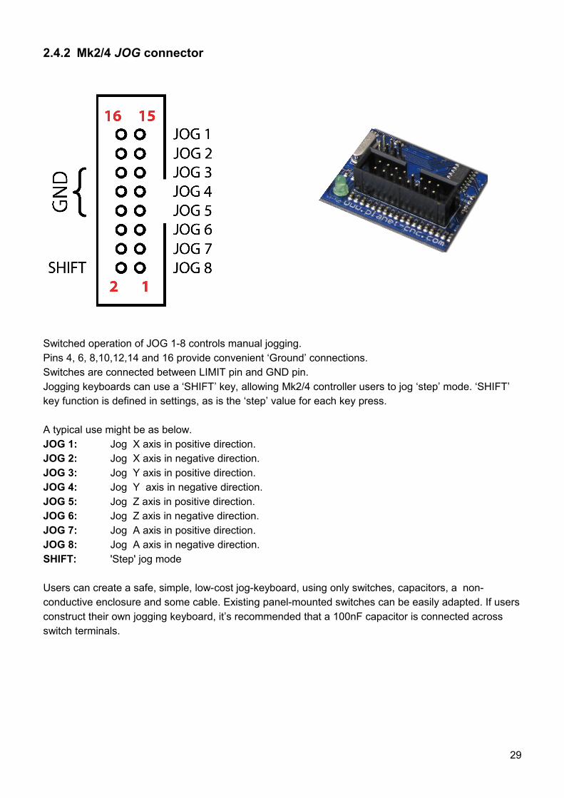
2.4.2 Mk2/4 JOG connector
Switched operation of JOG 1-8 controls manual jogging. Pins 4, 6, 8,10,12,14 and 16 provide convenient ‘Ground’ connections. Switches are connected between LIMIT pin and GND pin.Jogging keyboards can use a ‘SHIFT’ key, allowing Mk2/4 controller users to jog ‘step’ mode. ‘SHIFT’ key function is defined in settings, as is the ‘step’ value for each key press.
A typical use might be as below.JOG 1: Jog X axis in positive direction.JOG 2: Jog X axis in negative direction.JOG 3: Jog Y axis in positive direction.JOG 4: Jog Y axis in negative direction.JOG 5: Jog Z axis in positive direction.JOG 6: Jog Z axis in negative direction.JOG 7: Jog A axis in positive direction.JOG 8: Jog A axis in negative direction.SHIFT: 'Step' jog mode
Users can create a safe, simple, low-cost jog-keyboard, using only switches, capacitors, a non-conductive enclosure and some cable. Existing panel-mounted switches can be easily adapted. If users construct their own jogging keyboard, it’s recommended that a 100nF capacitor is connected across switch terminals.
29
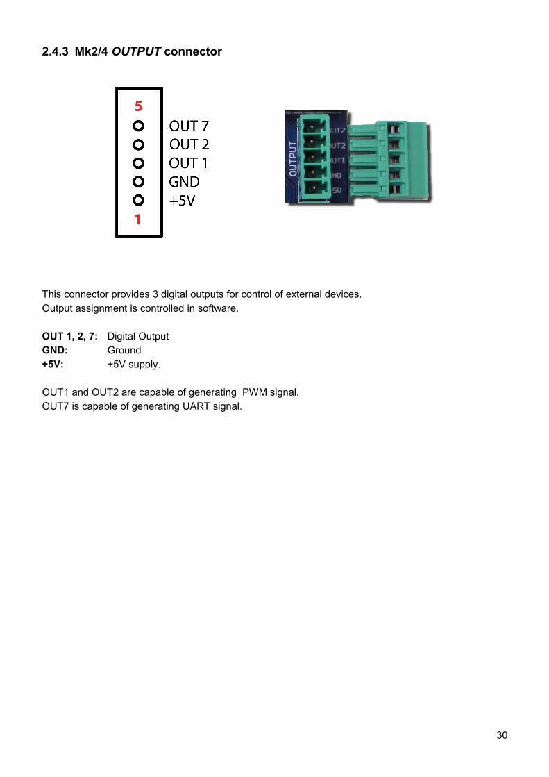
2.4.3 Mk2/4 OUTPUT connector
This connector provides 3 digital outputs for control of external devices. Output assignment is controlled in software.
OUT 1, 2, 7: Digital OutputGND: Ground+5V: +5V supply.
OUT1 and OUT2 are capable of generating PWM signal.OUT7 is capable of generating UART signal.
30
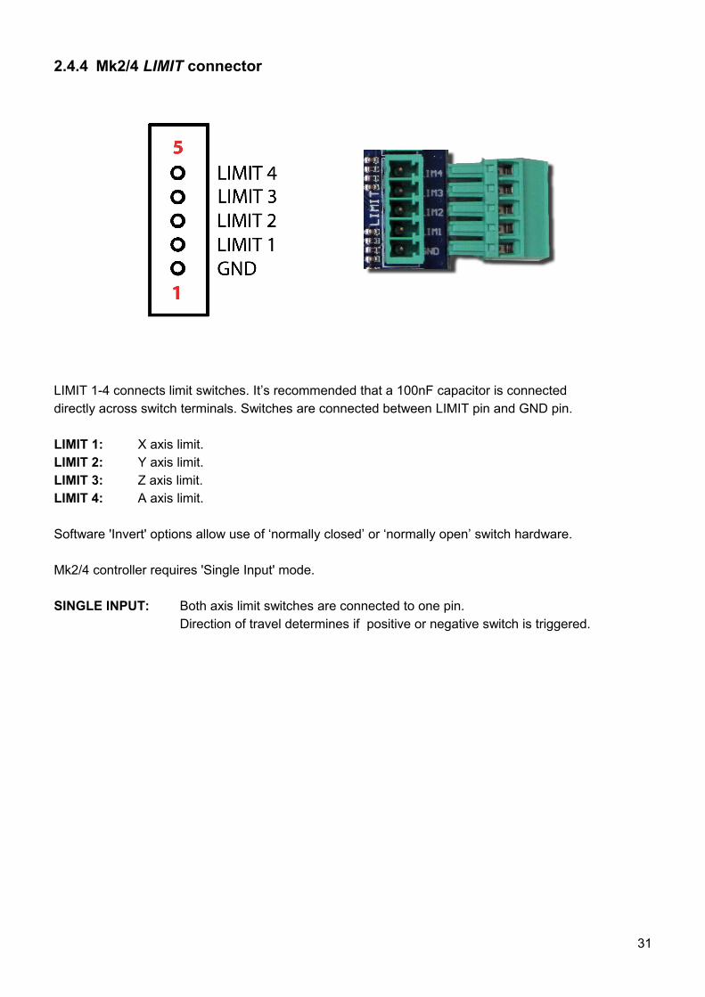
2.4.4 Mk2/4 LIMIT connector
LIMIT 1-4 connects limit switches. It’s recommended that a 100nF capacitor is connecteddirectly across switch terminals. Switches are connected between LIMIT pin and GND pin.
LIMIT 1: X axis limit.LIMIT 2: Y axis limit.LIMIT 3: Z axis limit.LIMIT 4: A axis limit.
Software 'Invert' options allow use of ‘normally closed’ or ‘normally open’ switch hardware.
Mk2/4 controller requires 'Single Input' mode.
SINGLE INPUT: Both axis limit switches are connected to one pin. Direction of travel determines if positive or negative switch is triggered.
31
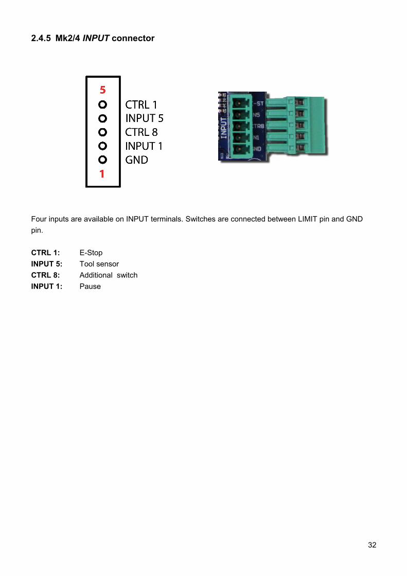
2.4.5 Mk2/4 INPUT connector
Four inputs are available on INPUT terminals. Switches are connected between LIMIT pin and GND pin.
CTRL 1: E-StopINPUT 5: Tool sensorCTRL 8: Additional switchINPUT 1: Pause
32
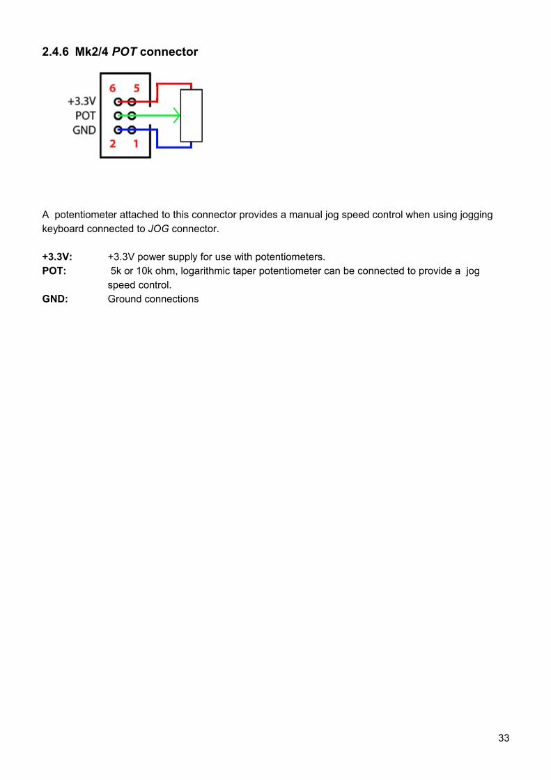
2.4.6 Mk2/4 POT connector
A potentiometer attached to this connector provides a manual jog speed control when using jogging keyboard connected to JOG connector.
+3.3V: +3.3V power supply for use with potentiometers. POT: 5k or 10k ohm, logarithmic taper potentiometer can be connected to provide a jog
speed control.GND: Ground connections
33
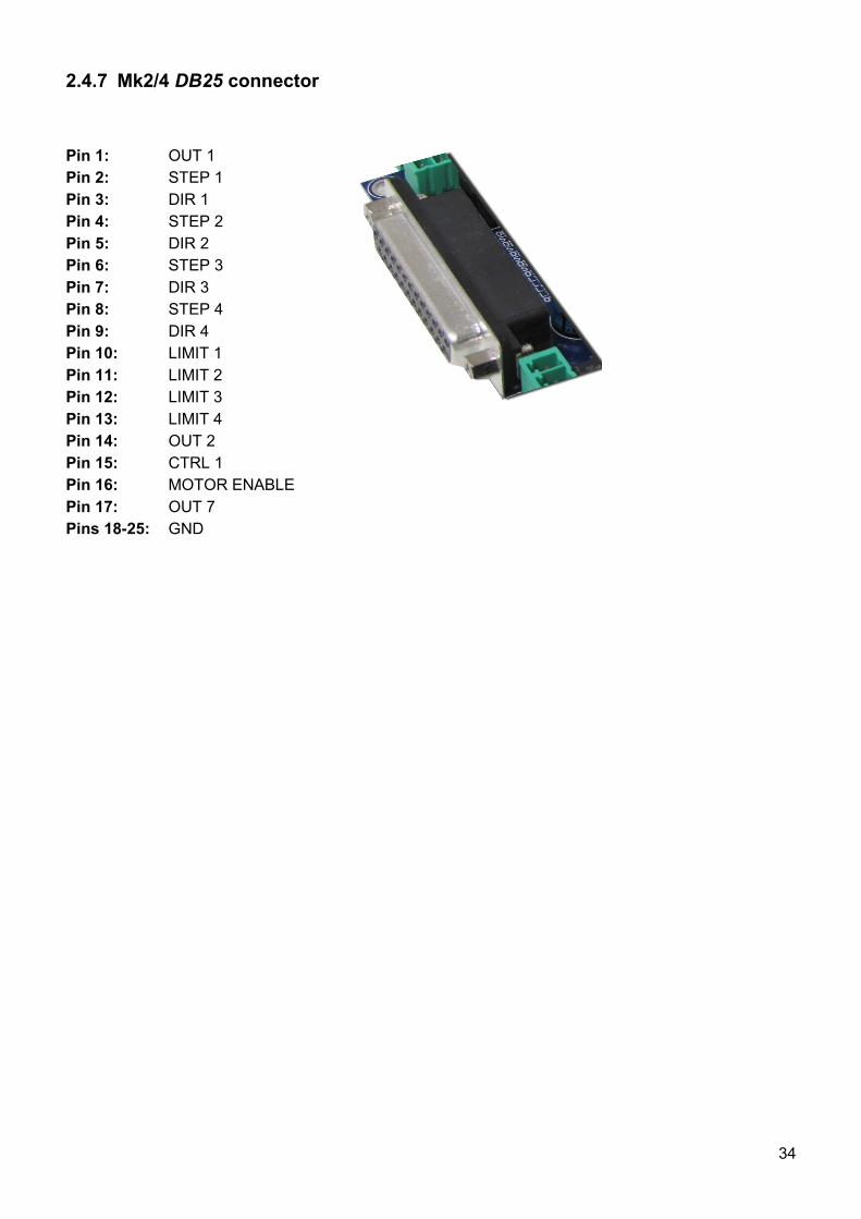
2.4.7 Mk2/4 DB25 connector
Pin 1: OUT 1Pin 2: STEP 1Pin 3: DIR 1Pin 4: STEP 2Pin 5: DIR 2Pin 6: STEP 3Pin 7: DIR 3Pin 8: STEP 4Pin 9: DIR 4Pin 10: LIMIT 1Pin 11: LIMIT 2Pin 12: LIMIT 3Pin 13: LIMIT 4Pin 14: OUT 2Pin 15: CTRL 1Pin 16: MOTOR ENABLEPin 17: OUT 7Pins 18-25: GND
34
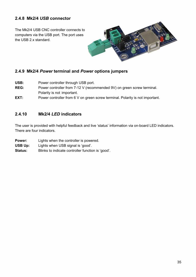
2.4.8 Mk2/4 USB connector
The Mk2/4 USB CNC controller connects to computers via the USB port. The port uses the USB 2.x standard.
2.4.9 Mk2/4 Power terminal and Power options jumpers
USB: Power controller through USB port.REG: Power controller from 7-12 V (recommended 9V) on green screw terminal.
Polarity is not important.EXT: Power controller from 6 V on green screw terminal. Polarity is not important.
2.4.10 Mk2/4 LED indicators
The user is provided with helpful feedback and live ‘status’ information via on-board LED indicators. There are four indicators.
Power: Lights when the controller is powered.USB Up: Lights when USB signal is ‘good’.Status: Blinks to indicate controller function is ‘good’.
35
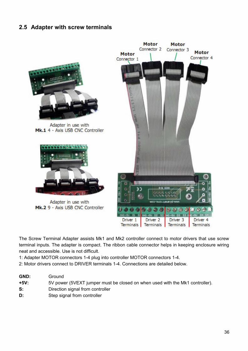
2.5 Adapter with screw terminals
The Screw Terminal Adapter assists Mk1 and Mk2 controller connect to motor drivers that use screw terminal inputs. The adapter is compact. The ribbon cable connector helps in keeping enclosure wiring neat and accessible. Use is not difficult.1: Adapter MOTOR connectors 1-4 plug into controller MOTOR connectors 1-4.2: Motor drivers connect to DRIVER terminals 1-4. Connections are detailed below.
GND: Ground+5V: 5V power (5VEXT jumper must be closed on when used with the Mk1 controller).S: Direction signal from controllerD: Step signal from controller
36
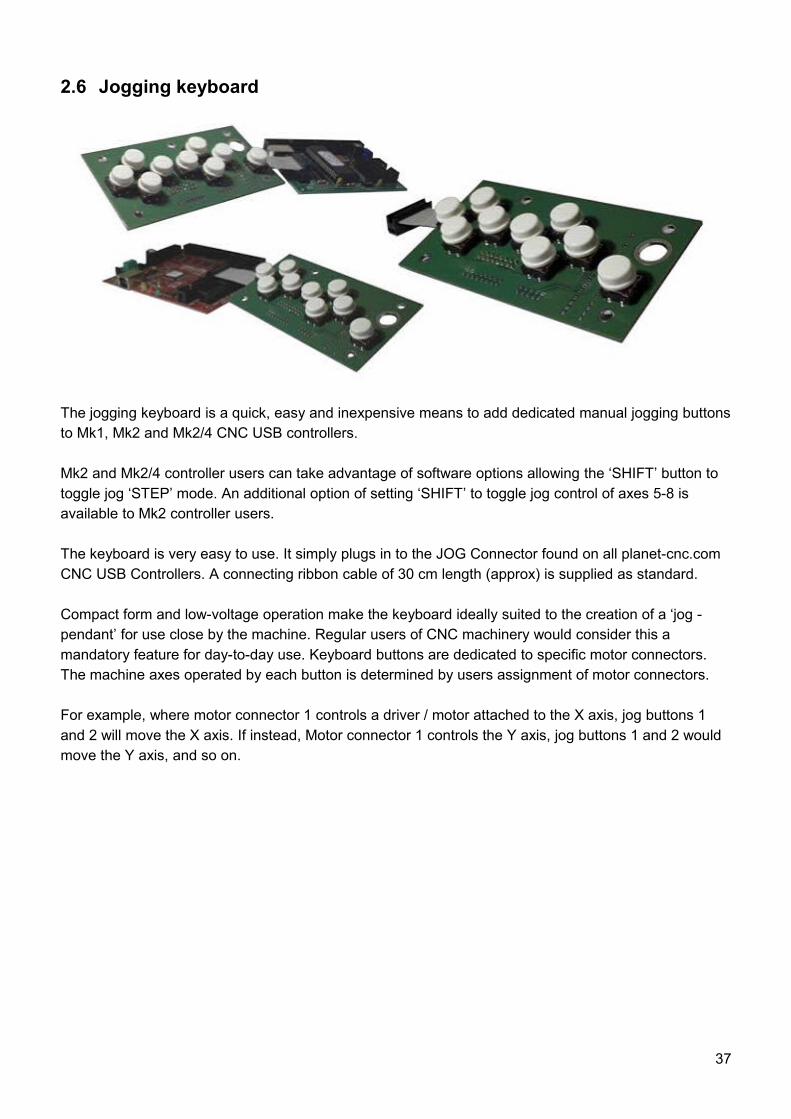
2.6 Jogging keyboard
The jogging keyboard is a quick, easy and inexpensive means to add dedicated manual jogging buttons to Mk1, Mk2 and Mk2/4 CNC USB controllers.
Mk2 and Mk2/4 controller users can take advantage of software options allowing the ‘SHIFT’ button to toggle jog ‘STEP’ mode. An additional option of setting ‘SHIFT’ to toggle jog control of axes 5-8 is available to Mk2 controller users.
The keyboard is very easy to use. It simply plugs in to the JOG Connector found on all planet-cnc.com CNC USB Controllers. A connecting ribbon cable of 30 cm length (approx) is supplied as standard.
Compact form and low-voltage operation make the keyboard ideally suited to the creation of a ‘jog - pendant’ for use close by the machine. Regular users of CNC machinery would consider this a mandatory feature for day-to-day use. Keyboard buttons are dedicated to specific motor connectors. The machine axes operated by each button is determined by users assignment of motor connectors.
For example, where motor connector 1 controls a driver / motor attached to the X axis, jog buttons 1 and 2 will move the X axis. If instead, Motor connector 1 controls the Y axis, jog buttons 1 and 2 would move the Y axis, and so on.
37
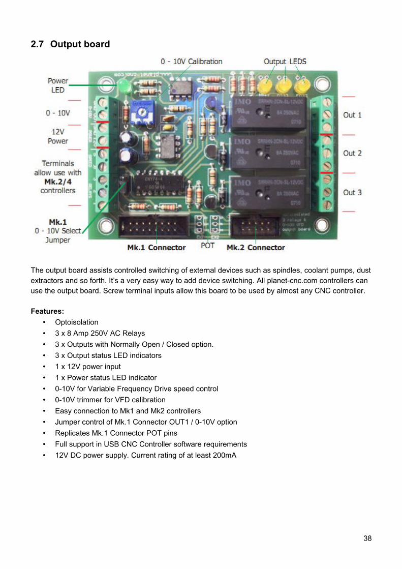
2.7 Output board
The output board assists controlled switching of external devices such as spindles, coolant pumps, dust extractors and so forth. It’s a very easy way to add device switching. All planet-cnc.com controllers can use the output board. Screw terminal inputs allow this board to be used by almost any CNC controller.
Features:• Optoisolation• 3 x 8 Amp 250V AC Relays• 3 x Outputs with Normally Open / Closed option.• 3 x Output status LED indicators• 1 x 12V power input• 1 x Power status LED indicator• 0-10V for Variable Frequency Drive speed control• 0-10V trimmer for VFD calibration• Easy connection to Mk1 and Mk2 controllers• Jumper control of Mk.1 Connector OUT1 / 0-10V option• Replicates Mk.1 Connector POT pins• Full support in USB CNC Controller software requirements• 12V DC power supply. Current rating of at least 200mA
38
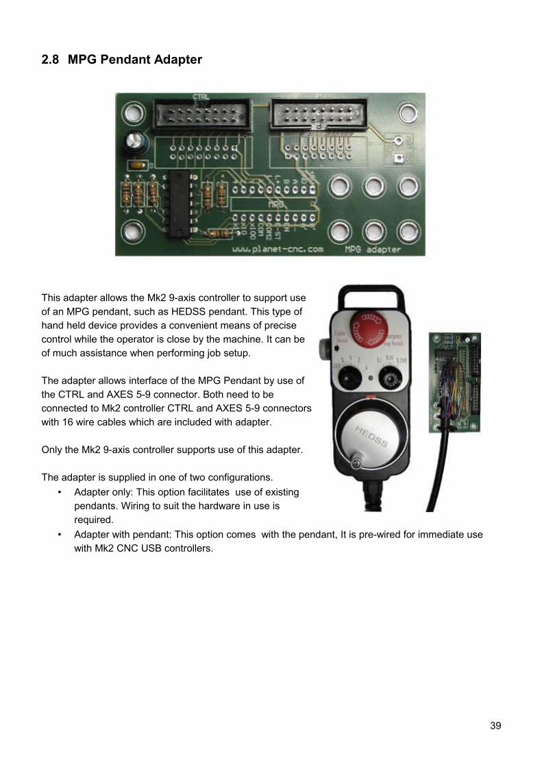
2.8 MPG Pendant Adapter
This adapter allows the Mk2 9-axis controller to support use of an MPG pendant, such as HEDSS pendant. This type of hand held device provides a convenient means of precise control while the operator is close by the machine. It can be of much assistance when performing job setup.
The adapter allows interface of the MPG Pendant by use of the CTRL and AXES 5-9 connector. Both need to be connected to Mk2 controller CTRL and AXES 5-9 connectors with 16 wire cables which are included with adapter.
Only the Mk2 9-axis controller supports use of this adapter.
The adapter is supplied in one of two configurations.• Adapter only: This option facilitates use of existing
pendants. Wiring to suit the hardware in use is required.
• Adapter with pendant: This option comes with the pendant, It is pre-wired for immediate use with Mk2 CNC USB controllers.
39

2.9 SD Card Adapter
SD card options for the Mk2 CNC USB Controller are in development. Use of this adapter, in conjunction with control buttons attached to the INPUT connector, will allow CNC machinery to run proven NC programs without need of an attached PC.
Pin-outs for this adapter correspond with Mk2 CNC USB controller EXT connector pins.The adapter can not be used with Mk1 or Mk2/4 controllers.
40
3 Software
3.1 Overview
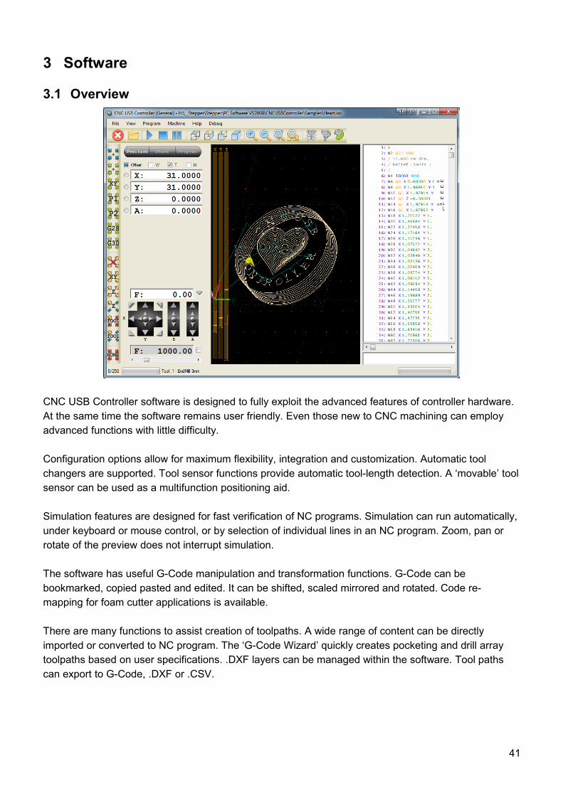
CNC USB Controller software is designed to fully exploit the advanced features of controller hardware. At the same time the software remains user friendly. Even those new to CNC machining can employ advanced functions with little difficulty.
Configuration options allow for maximum flexibility, integration and customization. Automatic tool changers are supported. Tool sensor functions provide automatic tool-length detection. A ‘movable’ tool sensor can be used as a multifunction positioning aid.
Simulation features are designed for fast verification of NC programs. Simulation can run automatically, under keyboard or mouse control, or by selection of individual lines in an NC program. Zoom, pan or rotate of the preview does not interrupt simulation.
The software has useful G-Code manipulation and transformation functions. G-Code can be bookmarked, copied pasted and edited. It can be shifted, scaled mirrored and rotated. Code re-mapping for foam cutter applications is available.
There are many functions to assist creation of toolpaths. A wide range of content can be directly imported or converted to NC program. The ‘G-Code Wizard’ quickly creates pocketing and drill array toolpaths based on user specifications. .DXF layers can be managed within the software. Tool paths can export to G-Code, .DXF or .CSV.
41
3.2 InstallationCNC USB Controller software is compatible with Windows XP, Vista or Windows 7 (32 or 64 bit). Installation is a two-part process. Driver installation is performed, after which the main application can be installed and configured. The installation process is largely ‘automatic.’ In most cases it’s possible to accept ‘default’ options.
Windows 7 will display a ‘publisher verification’ request. This is simply a Windows 7 feature. It occurs when software from any publishers who are not part of the Microsoft ‘verification’ process is installed.
Some computers may require additional components to be installed. This is largely governed by the operating system and the installed software. More recent Microsoft releases contain these elements as part of the operating system. Older versions may not have them if software installed on the machine has not required their use.
Requirements:DirectX 9c for .NETMicrosoft .NET 3.5 SP1 Framework
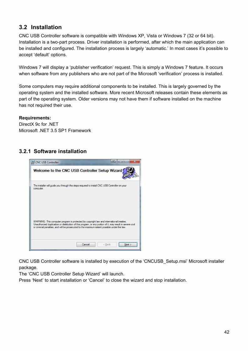
3.2.1 Software installation
CNC USB Controller software is installed by execution of the ‘CNCUSB_Setup.msi’ Microsoft installer package. The ‘CNC USB Controller Setup Wizard’ will launch.Press ‘Next’ to start installation or ‘Cancel’ to close the wizard and stop installation.
42
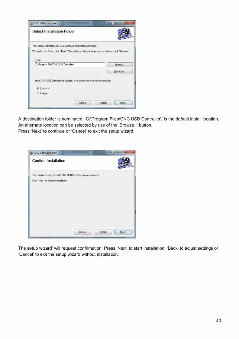
A destination folder is nominated. ‘C:\Program Files\CNC USB Controller\’ is the default install location. An alternate location can be selected by use of the ‘Browse..’ button.Press ‘Next’ to continue or ‘Cancel’ to exit the setup wizard.
The setup wizard’ will request confirmation. Press ‘Next’ to start installation, ‘Back’ to adjust settings or ‘Cancel’ to exit the setup wizard without installation.
43
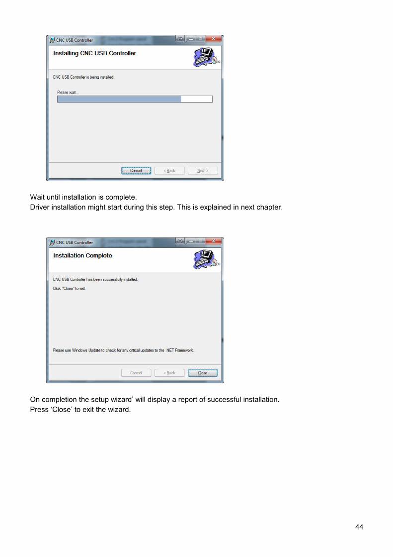
Wait until installation is complete.Driver installation might start during this step. This is explained in next chapter.
On completion the setup wizard’ will display a report of successful installation. Press ‘Close’ to exit the wizard.
44
3.2.2 Driver installation
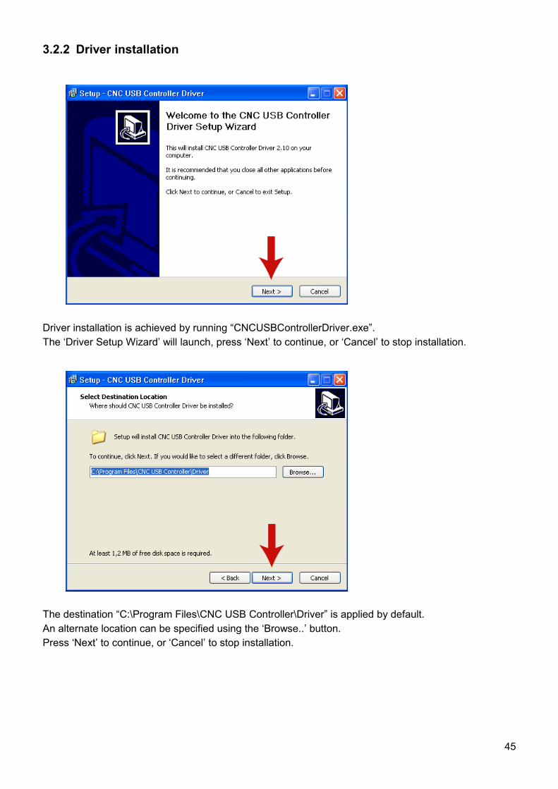
Driver installation is achieved by running “CNCUSBControllerDriver.exe”. The ‘Driver Setup Wizard’ will launch, press ‘Next’ to continue, or ‘Cancel’ to stop installation.
The destination “C:\Program Files\CNC USB Controller\Driver” is applied by default.An alternate location can be specified using the ‘Browse..’ button. Press ‘Next’ to continue, or ‘Cancel’ to stop installation.
45
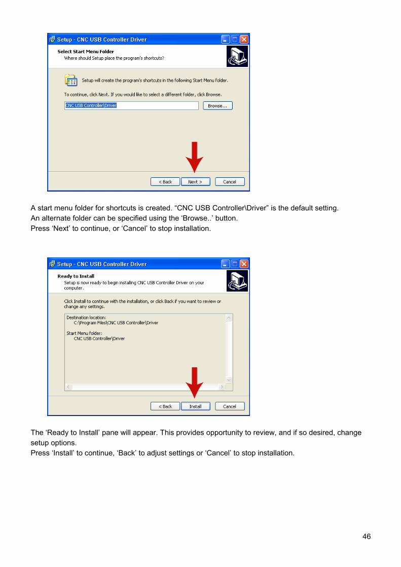
A start menu folder for shortcuts is created. “CNC USB Controller\Driver” is the default setting.An alternate folder can be specified using the ‘Browse..’ button.Press ‘Next’ to continue, or ‘Cancel’ to stop installation.
The ‘Ready to Install’ pane will appear. This provides opportunity to review, and if so desired, change setup options. Press ‘Install’ to continue, ‘Back’ to adjust settings or ‘Cancel’ to stop installation.
46
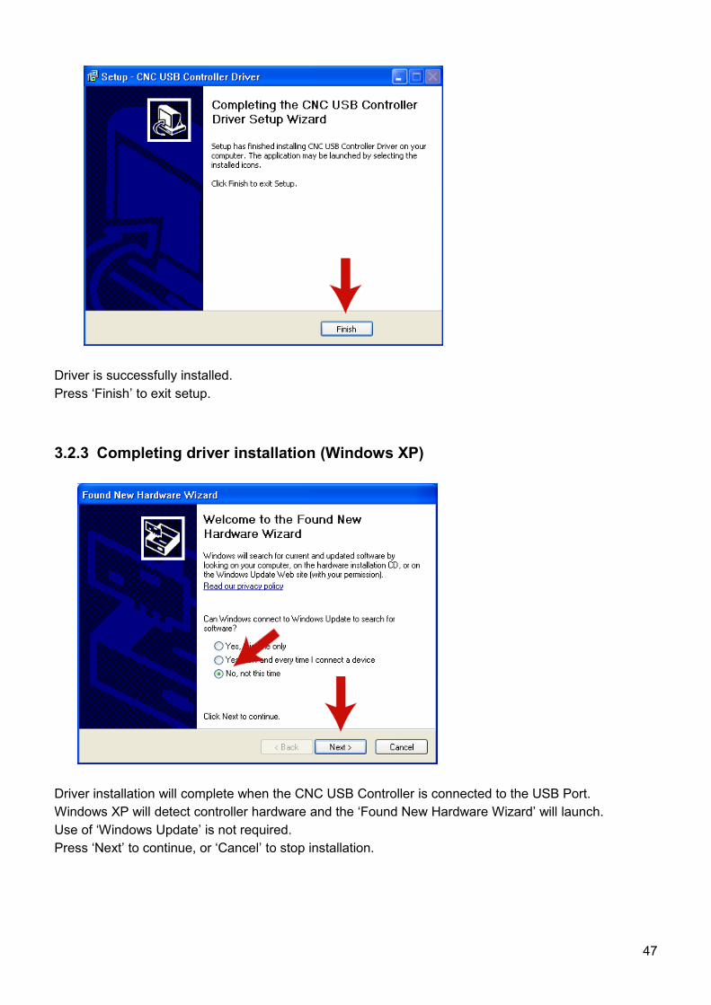
Driver is successfully installed.Press ‘Finish’ to exit setup.
3.2.3 Completing driver installation (Windows XP)
Driver installation will complete when the CNC USB Controller is connected to the USB Port. Windows XP will detect controller hardware and the ‘Found New Hardware Wizard’ will launch. Use of ‘Windows Update’ is not required.Press ‘Next’ to continue, or ‘Cancel’ to stop installation.
47
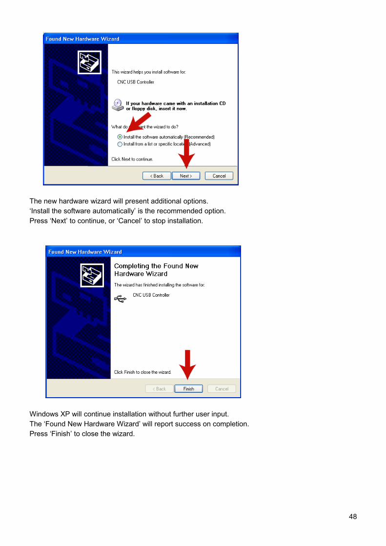
The new hardware wizard will present additional options.‘Install the software automatically’ is the recommended option.Press ‘Next’ to continue, or ‘Cancel’ to stop installation.
Windows XP will continue installation without further user input. The ‘Found New Hardware Wizard’ will report success on completion.Press ‘Finish’ to close the wizard.
48
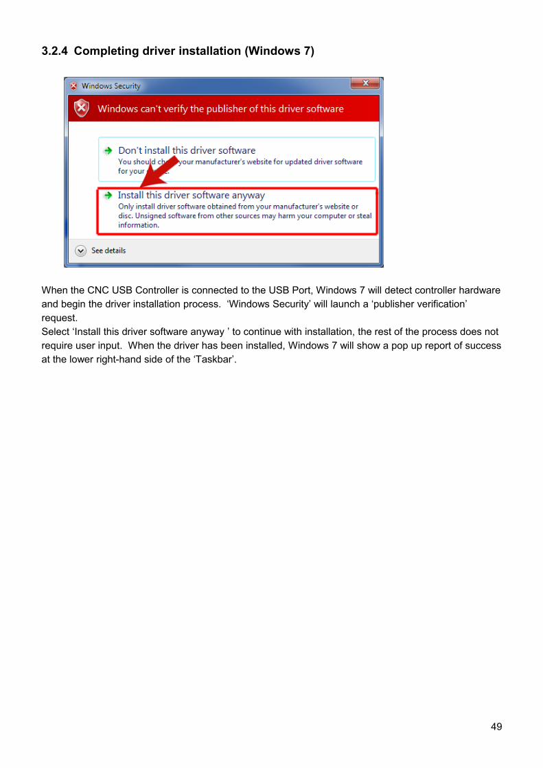
3.2.4 Completing driver installation (Windows 7)
When the CNC USB Controller is connected to the USB Port, Windows 7 will detect controller hardware and begin the driver installation process. ‘Windows Security’ will launch a ‘publisher verification’ request.Select ‘Install this driver software anyway ’ to continue with installation, the rest of the process does not require user input. When the driver has been installed, Windows 7 will show a pop up report of success at the lower right-hand side of the ‘Taskbar’.
49
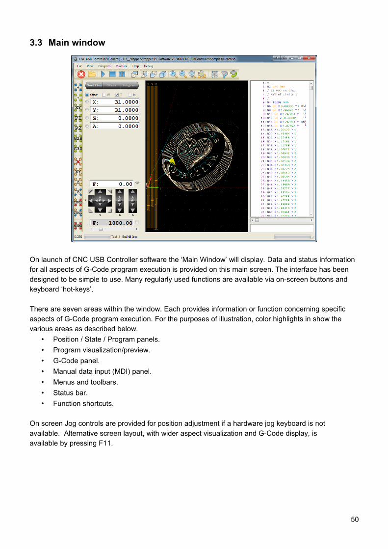
3.3 Main window
On launch of CNC USB Controller software the ‘Main Window’ will display. Data and status information for all aspects of G-Code program execution is provided on this main screen. The interface has been designed to be simple to use. Many regularly used functions are available via on-screen buttons and keyboard ‘hot-keys’.
There are seven areas within the window. Each provides information or function concerning specific aspects of G-Code program execution. For the purposes of illustration, color highlights in show the various areas as described below.
• Position / State / Program panels.• Program visualization/preview.• G-Code panel.• Manual data input (MDI) panel.• Menus and toolbars.• Status bar.• Function shortcuts.
On screen Jog controls are provided for position adjustment if a hardware jog keyboard is notavailable. Alternative screen layout, with wider aspect visualization and G-Code display, isavailable by pressing F11.
50
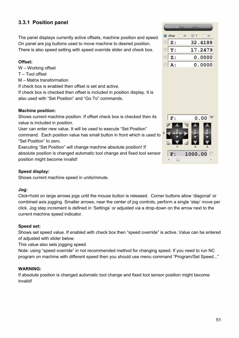
3.3.1 Position panel
The panel displays currently active offsets, machine position and speed. On panel are jog buttons used to move machine to desired position.There is also speed setting with speed override slider and check box.
Offset:W – Working offsetT – Tool offsetM – Matrix transformationIf check box is enabled then offset is set and active. If check box is checked then offset is included in position display. It is also used with “Set Position” and “Go To” commands.
Machine position:Shows current machine position. If offset check box is checked then its value is included in position.User can enter new value. It will be used to execute “Set Position” command. Each position value has small button in front which is used to “Set Position” to zero.Executing “Set Position” will change machine absolute position! If absolute position is changed automatic tool change and fixed tool sensor position might become invalid!
Speed display:Shows current machine speed in units/minute.
Jog:Click+hold on large arrows jogs until the mouse button is released. Corner buttons allow ‘diagonal’ or combined axis jogging. Smaller arrows, near the center of jog controls, perform a single ‘step’ move per click. Jog step increment is defined in ‘Settings’ or adjusted via a drop-down on the arrow next to the current machine speed indicator.
Speed set:Shows set speed value. If enabled with check box then “speed override” is active. Value can be entered of adjusted with slider below.This value also sets jogging speed.Note: using “speed override” in not recommended method for changing speed. If you need to run NC program on machine with different speed then you should use menu command “Program/Set Speed...”
WARNING:If absolute position is changed automatic tool change and fixed tool sensor position might become invalid!
51
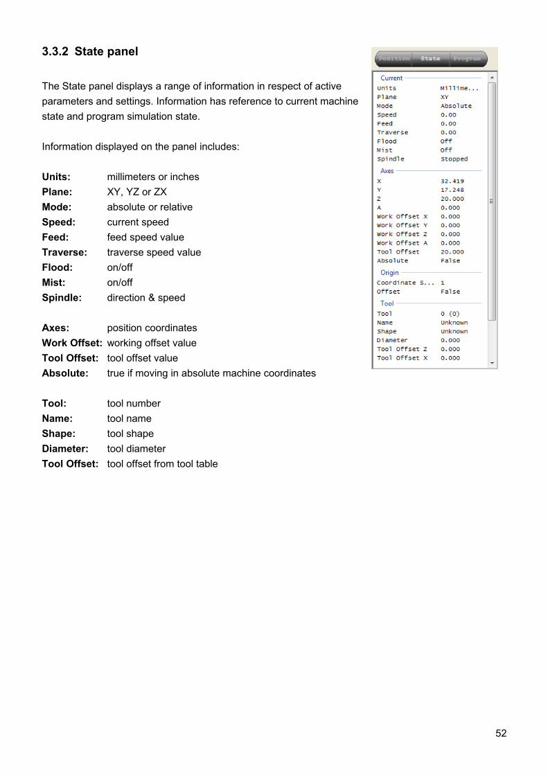
3.3.2 State panel
The State panel displays a range of information in respect of active parameters and settings. Information has reference to current machine state and program simulation state.
Information displayed on the panel includes:
Units: millimeters or inchesPlane: XY, YZ or ZXMode: absolute or relativeSpeed: current speedFeed: feed speed valueTraverse: traverse speed valueFlood: on/offMist: on/offSpindle: direction & speed
Axes: position coordinatesWork Offset: working offset valueTool Offset: tool offset valueAbsolute: true if moving in absolute machine coordinates
Tool: tool numberName: tool nameShape: tool shapeDiameter: tool diameterTool Offset: tool offset from tool table
52
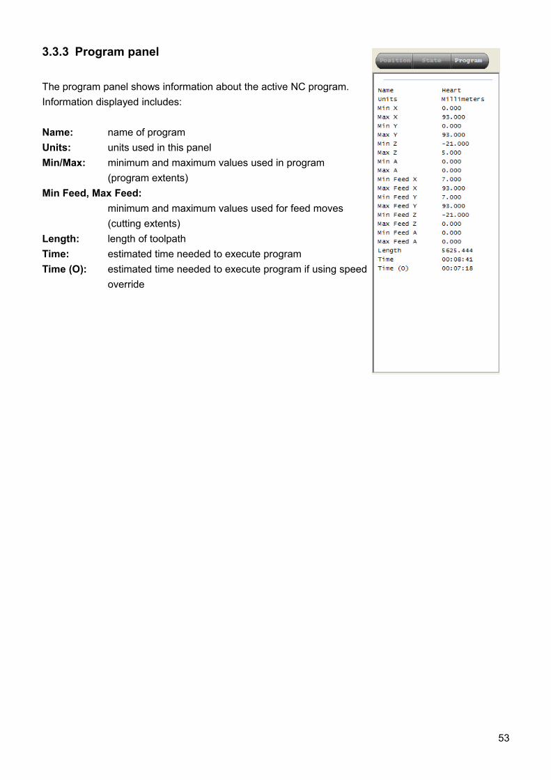
3.3.3 Program panel
The program panel shows information about the active NC program. Information displayed includes:
Name: name of programUnits: units used in this panelMin/Max: minimum and maximum values used in program
(program extents)Min Feed, Max Feed:
minimum and maximum values used for feed moves (cutting extents)
Length: length of toolpathTime: estimated time needed to execute programTime (O): estimated time needed to execute program if using speed
override
53
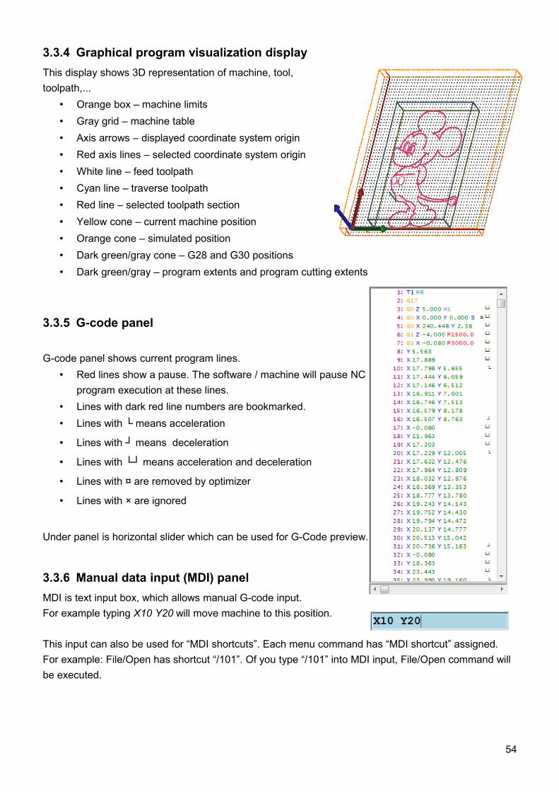
3.3.4 Graphical program visualization displayThis display shows 3D representation of machine, tool, toolpath,...
• Orange box – machine limits• Gray grid – machine table• Axis arrows – displayed coordinate system origin• Red axis lines – selected coordinate system origin• White line – feed toolpath• Cyan line – traverse toolpath• Red line – selected toolpath section• Yellow cone – current machine position• Orange cone – simulated position• Dark green/gray cone – G28 and G30 positions• Dark green/gray – program extents and program cutting extents
3.3.5 G-code panel
G-code panel shows current program lines. • Red lines show a pause. The software / machine will pause NC
program execution at these lines. • Lines with dark red line numbers are bookmarked.• Lines with └ means acceleration
• Lines with ┘ means deceleration
• Lines with └┘ means acceleration and deceleration
• Lines with ¤ are removed by optimizer
• Lines with × are ignored
Under panel is horizontal slider which can be used for G-Code preview.
3.3.6 Manual data input (MDI) panelMDI is text input box, which allows manual G-code input.For example typing X10 Y20 will move machine to this position.
This input can also be used for “MDI shortcuts”. Each menu command has “MDI shortcut” assigned.For example: File/Open has shortcut “/101”. Of you type “/101” into MDI input, File/Open command will be executed.
54
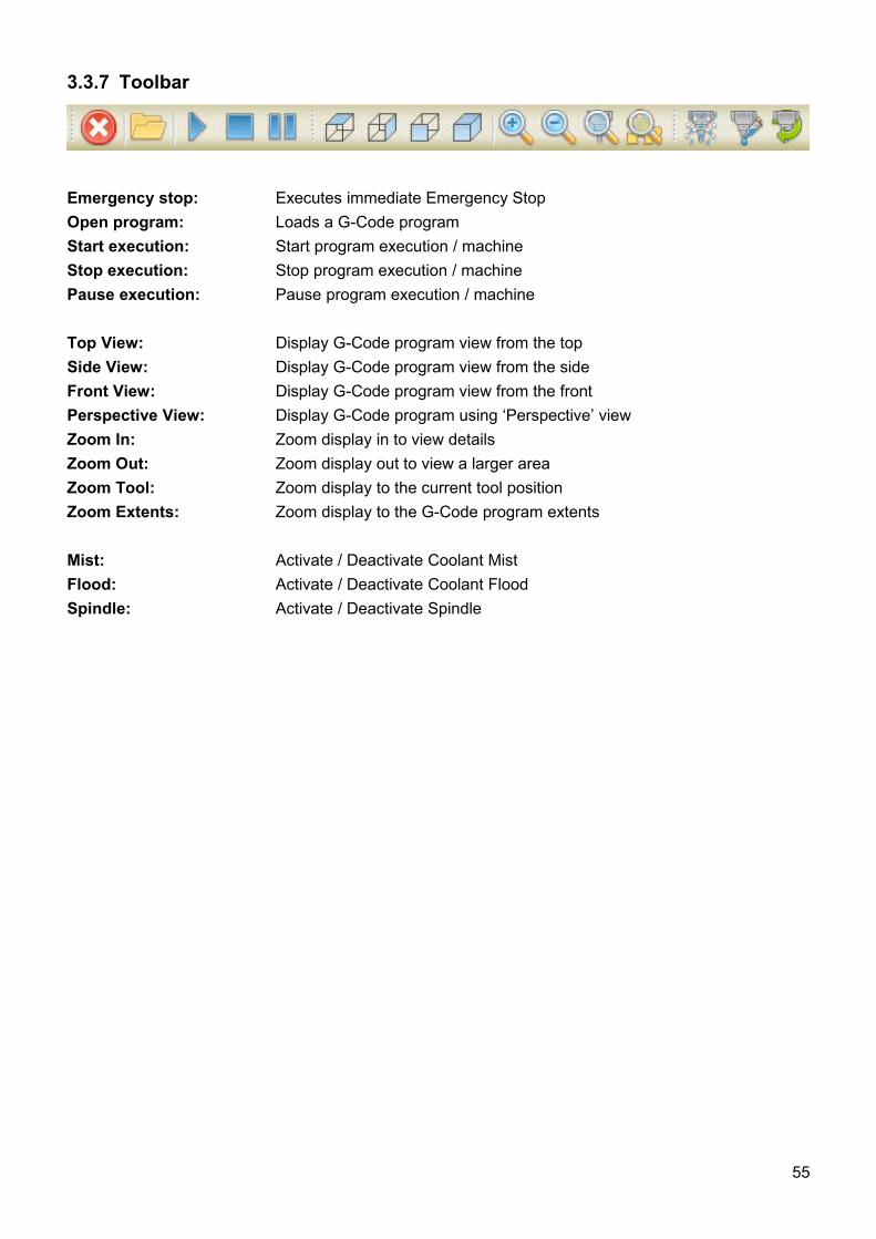
3.3.7 Toolbar
Emergency stop: Executes immediate Emergency StopOpen program: Loads a G-Code programStart execution: Start program execution / machineStop execution: Stop program execution / machinePause execution: Pause program execution / machine
Top View: Display G-Code program view from the topSide View: Display G-Code program view from the sideFront View: Display G-Code program view from the frontPerspective View: Display G-Code program using ‘Perspective’ viewZoom In: Zoom display in to view detailsZoom Out: Zoom display out to view a larger areaZoom Tool: Zoom display to the current tool positionZoom Extents: Zoom display to the G-Code program extents
Mist: Activate / Deactivate Coolant MistFlood: Activate / Deactivate Coolant FloodSpindle: Activate / Deactivate Spindle
55
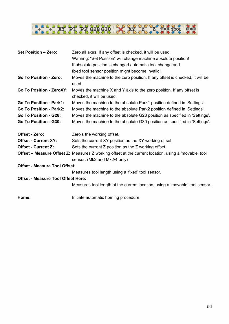
Set Position – Zero: Zero all axes. If any offset is checked, it will be used. Warning: “Set Position” will change machine absolute position! If absolute position is changed automatic tool change and fixed tool sensor position might become invalid!
Go To Position - Zero: Moves the machine to the zero position. If any offset is checked, it will be used.
Go To Position - ZeroXY: Moves the machine X and Y axis to the zero position. If any offset is checked, it will be used.
Go To Position - Park1: Moves the machine to the absolute Park1 position defined in ‘Settings’.Go To Position - Park2: Moves the machine to the absolute Park2 position defined in ‘Settings’.Go To Position - G28: Moves the machine to the absolute G28 position as specified in ‘Settings’.Go To Position - G30: Moves the machine to the absolute G30 position as specified in ‘Settings’.
Offset - Zero: Zero’s the working offset.Offset - Current XY: Sets the current XY position as the XY working offset.Offset - Current Z: Sets the current Z position as the Z working offset.Offset – Measure Offset Z: Measures Z working offset at the current location, using a ‘movable’ tool
sensor. (Mk2 and Mk2/4 only)Offset - Measure Tool Offset:
Measures tool length using a ‘fixed’ tool sensor.Offset - Measure Tool Offset Here:
Measures tool length at the current location, using a ‘movable’ tool sensor.
Home: Initiate automatic homing procedure.
56
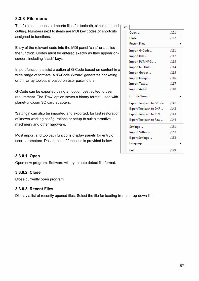
3.3.8 File menuThe file menu opens or imports files for toolpath, simulation and cutting. Numbers next to items are MDI key codes or shortcuts assigned to functions.
Entry of the relevant code into the MDI panel ‘calls’ or applies the function. Codes must be entered exactly as they appear on-screen, including ‘slash’ keys.
Import functions assist creation of G-Code based on content in a wide range of formats. A ‘G-Code Wizard’ generates pocketing or drill array toolpaths based on user parameters.
G-Code can be exported using an option best suited to user requirement. The ‘Raw’ option saves a binary format, used with planet-cnc.com SD card adapters.
‘Settings’ can also be imported and exported, for fast restoration of known working configurations or setup to suit alternative machinery and other hardware.
Most import and toolpath functions display panels for entry of user parameters. Description of functions is provided below.
3.3.8.1 OpenOpen new program. Software will try to auto detect file format.
3.3.8.2 CloseClose currently open program.
3.3.8.3 Recent FilesDisplay a list of recently opened files. Select the file for loading from a drop-down list.
57
3.3.8.4 Import G-CodeImport G-Code program.
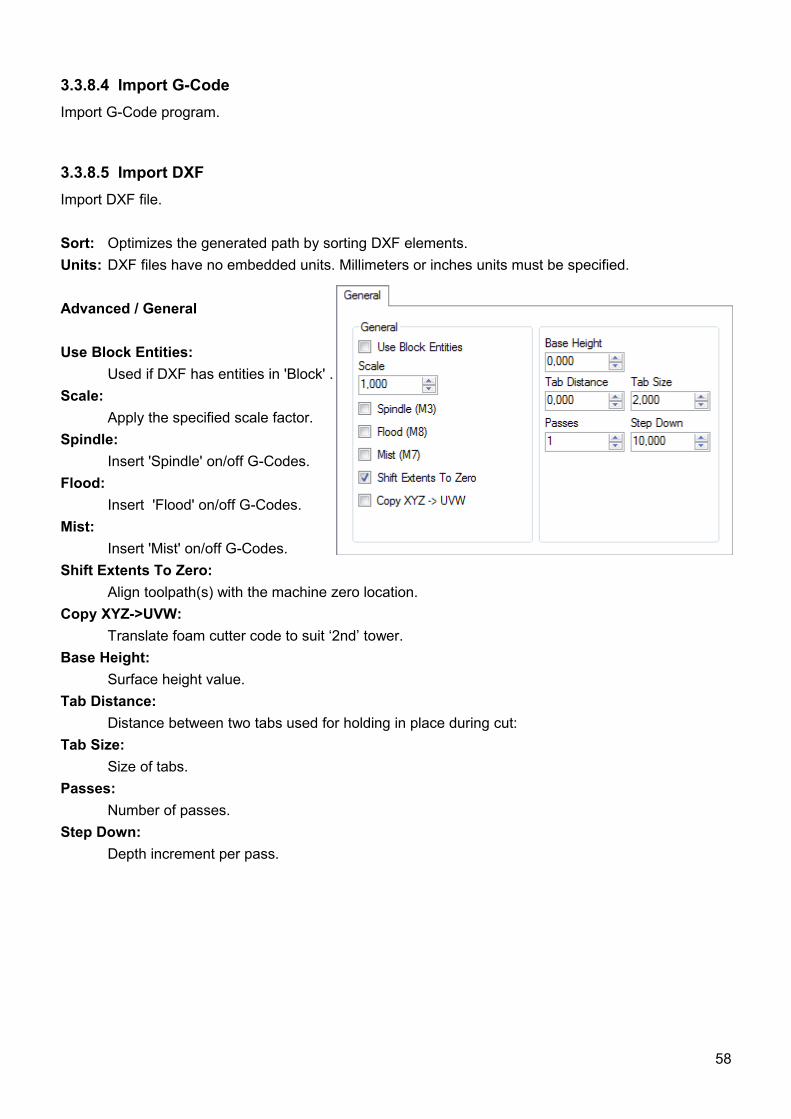
3.3.8.5 Import DXFImport DXF file.
Sort: Optimizes the generated path by sorting DXF elements. Units: DXF files have no embedded units. Millimeters or inches units must be specified.
Advanced / General
Use Block Entities:Used if DXF has entities in 'Block' .
Scale:Apply the specified scale factor.
Spindle:Insert 'Spindle' on/off G-Codes.
Flood:Insert 'Flood' on/off G-Codes.
Mist:Insert 'Mist' on/off G-Codes.
Shift Extents To Zero:Align toolpath(s) with the machine zero location.
Copy XYZ->UVW:Translate foam cutter code to suit ‘2nd’ tower.
Base Height:Surface height value.
Tab Distance:Distance between two tabs used for holding in place during cut:
Tab Size:Size of tabs.
Passes:Number of passes.
Step Down:Depth increment per pass.
58
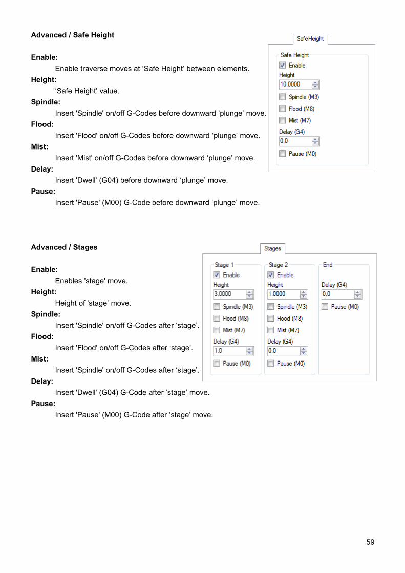
Advanced / Safe Height
Enable:Enable traverse moves at ‘Safe Height’ between elements.
Height:‘Safe Height’ value.
Spindle:Insert 'Spindle' on/off G-Codes before downward ‘plunge’ move.
Flood:Insert 'Flood' on/off G-Codes before downward ‘plunge’ move.
Mist:Insert 'Mist' on/off G-Codes before downward ‘plunge’ move.
Delay:Insert 'Dwell' (G04) before downward ‘plunge’ move.
Pause:Insert 'Pause' (M00) G-Code before downward ‘plunge’ move.
Advanced / Stages
Enable:Enables 'stage' move.
Height:Height of ‘stage’ move.
Spindle:Insert 'Spindle' on/off G-Codes after ‘stage’.
Flood:Insert 'Flood' on/off G-Codes after ‘stage’.
Mist:Insert 'Spindle' on/off G-Codes after ‘stage’.
Delay:Insert 'Dwell' (G04) G-Code after ‘stage’ move.
Pause:Insert 'Pause' (M00) G-Code after ‘stage’ move.
59
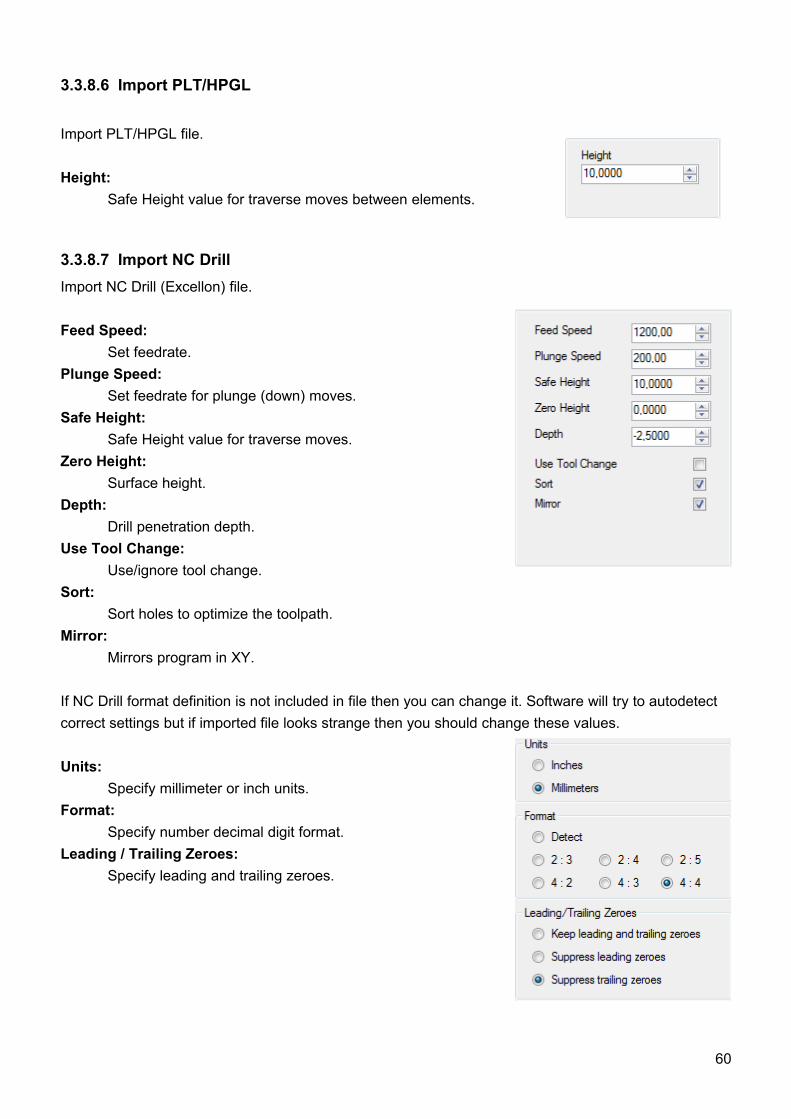
3.3.8.6 Import PLT/HPGL
Import PLT/HPGL file.
Height:Safe Height value for traverse moves between elements.
3.3.8.7 Import NC DrillImport NC Drill (Excellon) file.
Feed Speed: Set feedrate.
Plunge Speed: Set feedrate for plunge (down) moves.
Safe Height: Safe Height value for traverse moves.
Zero Height: Surface height.
Depth: Drill penetration depth.
Use Tool Change: Use/ignore tool change.
Sort: Sort holes to optimize the toolpath.
Mirror:Mirrors program in XY.
If NC Drill format definition is not included in file then you can change it. Software will try to autodetect correct settings but if imported file looks strange then you should change these values.
Units:Specify millimeter or inch units.
Format:Specify number decimal digit format.
Leading / Trailing Zeroes:Specify leading and trailing zeroes.
60
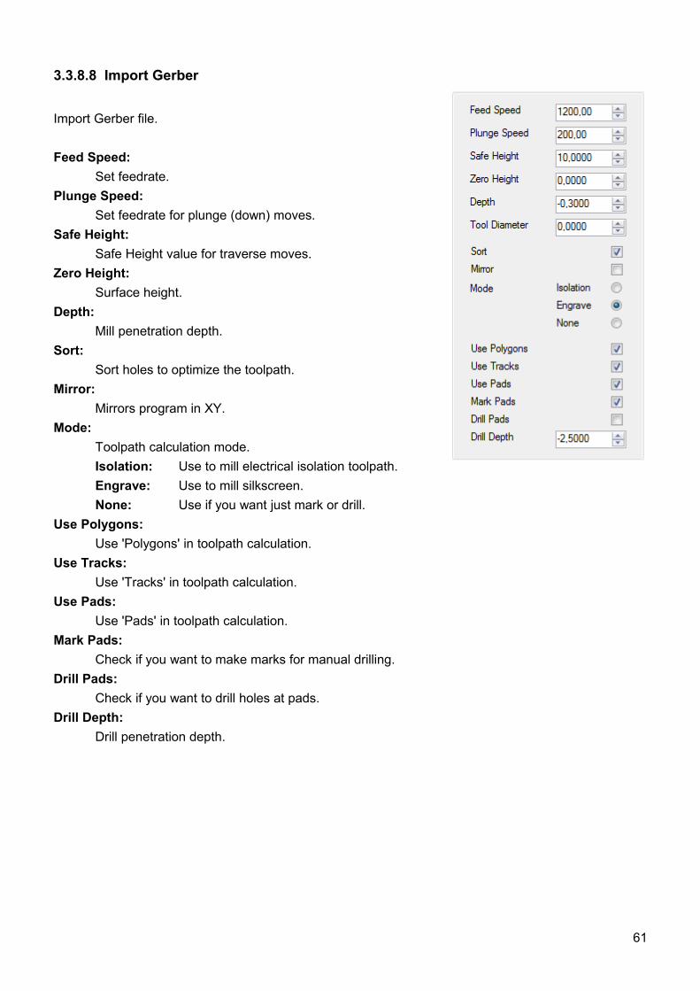
3.3.8.8 Import Gerber
Import Gerber file.
Feed Speed: Set feedrate.
Plunge Speed: Set feedrate for plunge (down) moves.
Safe Height: Safe Height value for traverse moves.
Zero Height: Surface height.
Depth: Mill penetration depth.
Sort: Sort holes to optimize the toolpath.
Mirror:Mirrors program in XY.
Mode:Toolpath calculation mode.Isolation: Use to mill electrical isolation toolpath.Engrave: Use to mill silkscreen.None: Use if you want just mark or drill.
Use Polygons:Use 'Polygons' in toolpath calculation.
Use Tracks:Use 'Tracks' in toolpath calculation.
Use Pads:Use 'Pads' in toolpath calculation.
Mark Pads:Check if you want to make marks for manual drilling.
Drill Pads:Check if you want to drill holes at pads.
Drill Depth:Drill penetration depth.
61
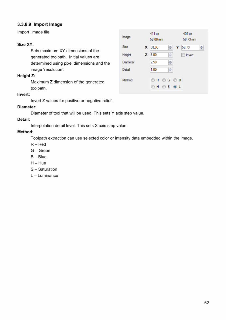
3.3.8.9 Import ImageImport image file.
Size XY: Sets maximum XY dimensions of the generated toolpath. Initial values are determined using pixel dimensions and the image ‘resolution’.
Height Z:Maximum Z dimension of the generated toolpath.
Invert: Invert Z values for positive or negative relief.
Diameter:Diameter of tool that will be used. This sets Y axis step value.
Detail: Interpolation detail level. This sets X axis step value.Method:
Toolpath extraction can use selected color or intensity data embedded within the image.R – RedG – GreenB – BlueH – HueS – SaturationL – Luminance
62
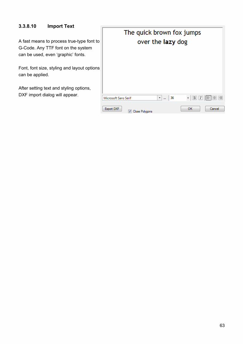
3.3.8.10 Import Text
A fast means to process true-type font to G-Code. Any TTF font on the system can be used, even ‘graphic’ fonts.
Font, font size, styling and layout options can be applied.
After setting text and styling options, DXF import dialog will appear.
63
3.3.8.11 Import Airfoil
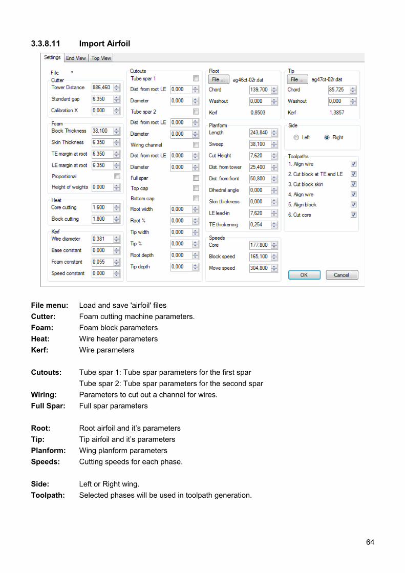
File menu: Load and save 'airfoil' files Cutter: Foam cutting machine parameters.Foam: Foam block parametersHeat: Wire heater parametersKerf: Wire parameters
Cutouts: Tube spar 1: Tube spar parameters for the first sparTube spar 2: Tube spar parameters for the second spar
Wiring: Parameters to cut out a channel for wires.Full Spar: Full spar parameters
Root: Root airfoil and it’s parametersTip: Tip airfoil and it’s parametersPlanform: Wing planform parametersSpeeds: Cutting speeds for each phase.
Side: Left or Right wing.Toolpath: Selected phases will be used in toolpath generation.
64
3.3.8.12 G-Code Wizard
Various wizards for different tasks.
3.3.8.13 Export Toolpath To G-codeExport toolpath to G-code file.
3.3.8.14 Export Toolpath to DXFExport toolpath to DXF file. Created file also contains traverse moves at safe height.
3.3.8.15 Export Toolpath to CSVExport toolpath to CSV file. Created list of points contains toolpath points.
3.3.8.16 Export Toolpath to RAWExport toolpath to RAW file. RAW files are used with SD card.
3.3.8.17 SettingsDisplay settings dialog where you configure software to suit hardware requirements.A separate chapter describes settings dialog.
3.3.8.18 Import SettingsImport a ‘Settings’ file to quickly restore a known working configuration or to re-configure CNC USBController software to suit different machines or applications.
3.3.8.19 Export SettingsSave the active ‘Settings’ file as a backup of the software/machine configuration. Custom optionscan be stored to quickly configure machines to user requirement.
3.3.8.20 LanguageSelect language of application from list of supported languages.
3.3.8.21 ExitCloses CNC USB Controller software. If the ‘E-Stop’ on exit feature is active, the machine performs an E-Stop. ‘Settings’ options allow E-Stop to deactivate spindles and interrupt all motor ‘ENABLE’ signals, disabling the machine if software is inactive.
65
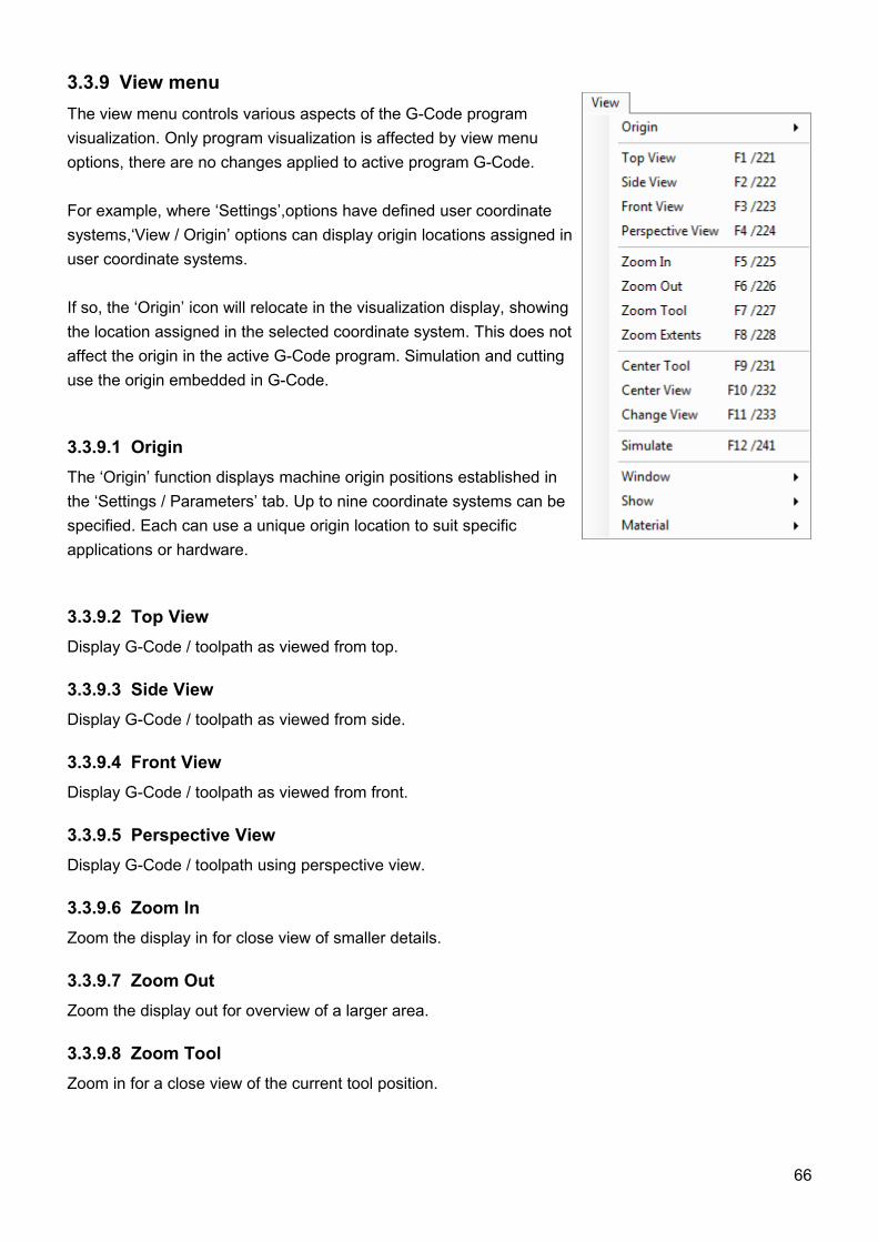
3.3.9 View menuThe view menu controls various aspects of the G-Code program visualization. Only program visualization is affected by view menu options, there are no changes applied to active program G-Code.
For example, where ‘Settings’,options have defined user coordinate systems,‘View / Origin’ options can display origin locations assigned in user coordinate systems.
If so, the ‘Origin’ icon will relocate in the visualization display, showing the location assigned in the selected coordinate system. This does not affect the origin in the active G-Code program. Simulation and cutting use the origin embedded in G-Code.
3.3.9.1 OriginThe ‘Origin’ function displays machine origin positions established in the ‘Settings / Parameters’ tab. Up to nine coordinate systems can be specified. Each can use a unique origin location to suit specific applications or hardware.
3.3.9.2 Top ViewDisplay G-Code / toolpath as viewed from top.
3.3.9.3 Side ViewDisplay G-Code / toolpath as viewed from side.
3.3.9.4 Front ViewDisplay G-Code / toolpath as viewed from front.
3.3.9.5 Perspective ViewDisplay G-Code / toolpath using perspective view.
3.3.9.6 Zoom InZoom the display in for close view of smaller details.
3.3.9.7 Zoom OutZoom the display out for overview of a larger area.
3.3.9.8 Zoom ToolZoom in for a close view of the current tool position.
66
3.3.9.9 Zoom ExtentsCenter and zoom display to view whole G-Code / toolpath.
3.3.9.10 Center ToolCenters the program visualization on the current tool position. Useful to ‘find’ and follow the tool when simulating large NC programs or if cut extents move the tool outside the displayed area.
3.3.9.11 Center ViewCenters program visualization based on NC program extents. Useful to quickly reorient the view if ‘Center Tool’ has been used and it’s desirable to restore a ‘full’ view.
3.3.9.12 Change ViewSwitch between horizontal and vertical position of G-code panel. Provides alternate view with wide aspect visualization and G-Code listing. This can be useful if G-Code lines or comments are wider than the ‘standard’ view will display or if program aspect ratio is more suited to this layout.
3.3.9.13 SimulateStarts / Stops animated simulation of G-Code programs.
Users can pan (left mouse button), rotate (right mouse button) and zoom (mouse wheel) without interruption of simulation.
Simulation does not apply programmed cutting speed. Shift + F12 increases simulation speed, Ctrl + F12 slows down simulation.
3.3.9.14 Window / JogOpens a jog panel maintaining on-screen jog functions.Click+hold on large arrows jogs until mouse button release. Corner buttons allow combined axis jogging. Small arrows, near the center of jog controls, perform a single ‘step’ move per click.
3.3.9.15 Window / ResetResets GUI to default size and position.
3.3.9.16 Window / LargeDisplays larger toolbar screen buttons, for use with a touchscreen display.
67

3.3.9.17 ShowThe ‘Show’ item opens a sub-menu of elements that can be displayed as part of G-Code visualizations. There are many helpful aids to provide useful feedback.
Use is fairly self-explanatory. Checked items are visible in visualizations, unchecked items are not.
3.3.9.18 Material‘Material’ opens a list of materials defined in ‘Settings’. Selected materials display as wireframe, showing stock extents or as a ‘solid’, complete with textured appearance.
68
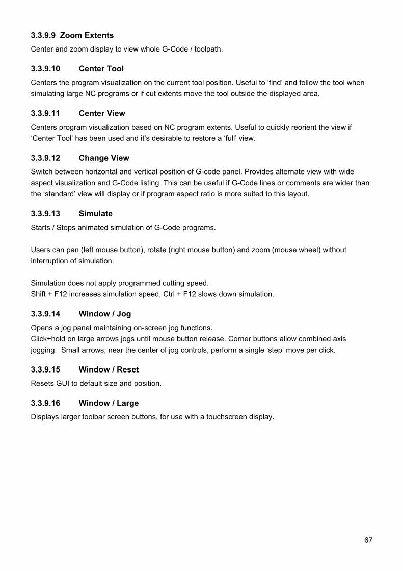
3.3.10 Program menuThe program menu provides G-Code processing functions to conform NC programs to user requirements. In most cases only parameter entry is required to make desired adjustments.
Functions to navigate NC programs and ‘bookmark’ blocks of code are also available. NC programs can be ‘sectioned’ by use of toolchange or pause codes.
Shift, Scale and Rotate can be applied to entire programs.These functions can assist with repeat usage of the same NC program or defined program block, for corners, patterns and so forth.
3.3.10.1 Lines‘Lines’ functions allow easy navigation of G-Code using G-Code commands as markers.
3.3.10.2 Bookmarks‘Bookmarks’ functions set and remove ‘bookmarks’ in G-Code and allow marked sections of code to beprocessed.
‘Bookmarks’ are applied to machining. Bookmarked sections of G-Code can be included, repeated or omitted. Machining can commence from or halt on ‘Bookmarks’.
‘Bookmarks’ are set by selection of the G-Code line where the bookmark is required and use of the‘Toggle’ item or press of the Tab key. Multiple lines can be bookmarked. When a line has been bookmarked it highlights.
Selection of a ‘Bookmark’ and press of the Tab key will clear it. Alternatively all ‘Bookmarks’ can be cleared at once using ‘Clear All’. When bookmarks are cleared the highlight is removed.
69
3.3.10.3 Shift'Shift' translates or moves the toolpath in 3D space using one of options.
User: Displays dialog allowing user specification of the distance to move the toolpath for each axis.
Extents to Zero: Aligns the ‘minimum’ edges of the toolpath extents with the machine zero position.
Extents to Position: Aligns the ‘minimum’ edges of the toolpath extents with the current machine position.
Center to Zero: Aligns the center point of the toolpath with the machine zero position.
Center to Position: Aligns the center point of the toolpath with the current machine position.
3.3.10.4 Scale'Scale' adjusts dimensions of the toolpath using ‘factor’ based scaling.
'Scale' opens the scale dialog. Default value of 1.00 is equivalent to 100% scale or actual size. A scale factor setting of 2.00 increases toolpath dimensions to 200% of the original size in the relevant axis.
3.3.10.5 Mirror'Mirror' function mirrors the toolpath about actual X, Y or Z axis. Axis of reflection is selected in the submenu.
3.3.10.6 Rotate'Rotate XY' rotates the toolpath XY plane with the origin as the center of rotation. Rotation angle is specified in dialog. Positive values rotate the toolpath in a clockwise direction. Negative values cause anti-clockwise rotation.
3.3.10.7 Set Speed'Set Speed' provides alternate means to specify feed and traverse motion rates applied in machining the G-Code program.
The panel will appear, allowing entry of user parameters. Pressing OK applies specifiedrates for feed and traverse moves. Current G-Code ‘F’ word values are overridden.
This is preferred method for changing speed. Use this and not “speed override” on main screen.
70
3.3.10.8 Copy XYZ → UVWG-Code applied to the XYZ or 1st tower is duplicated / modified to create code for the UVW or 2nd tower. For use with foam-cutters.
3.3.10.9 Swap XYZ ↔ UVWG-Code applied to the 1st and 2nd towers is exchanged / modified so that XYZ code becomes UVW code and vice verse. For use with foam-cutters. Example: Program is made to create left wing of plane. By use of swap command existing program creates right wing of plane.
3.3.10.10 Convert Arcs To LinesConverts Arc entities into segmented polylines. The value specified at 'Setting/Misc/Interpolation' determines line segment length.
3.3.10.11 Convert All To LinesConverts all entities into segmented polylines. The value specified at 'Setting/Misc/Interpolation' determines line segment length.
3.3.10.12 Edit G-CodeOpens a copy of the active NC program using the editor. A temporary filename is used, save does not overwrite the original file.
3.3.10.13 Edit DXFThe dialog will show, identifying layer content in the imported .DXF file. Entities within the DXF can be re-ordered or removed. The G-Code line where the entity appears in the file is identified. G-code describing the entity is selected.
When a entity is selected in the panel, it is highlighted in the visualization display. The code associated with the entity is selected in the G-Code panel listing.
A DXF file must first be imported or this function is unavailable.
3.3.10.14 Copy To ClipboardCopies entire contents of the G-Code panel to the windows clipboard.
3.3.10.15 Paste from ClipboardPastes windows clipboard content to the G-Code panel.
71
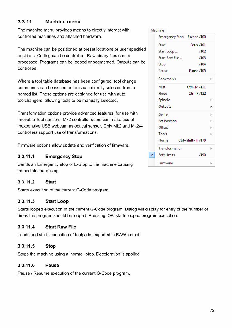
3.3.11 Machine menuThe machine menu provides means to directly interact with controlled machines and attached hardware.
The machine can be positioned at preset locations or user specified positions. Cutting can be controlled. Raw binary files can be processed. Programs can be looped or segmented. Outputs can be controlled.
Where a tool table database has been configured, tool change commands can be issued or tools can directly selected from a named list. These options are designed for use with auto toolchangers, allowing tools to be manually selected.
Transformation options provide advanced features, for use with ‘movable’ tool-sensors. Mk2 controller users can make use of inexpensive USB webcam as optical sensor. Only Mk2 and Mk2/4 controllers support use of transformations.
Firmware options allow update and verification of firmware.
3.3.11.1 Emergency StopSends an Emergency stop or E-Stop to the machine causing immediate ‘hard’ stop.
3.3.11.2 StartStarts execution of the current G-Code program.
3.3.11.3 Start LoopStarts looped execution of the current G-Code program. Dialog will display for entry of the number of times the program should be looped. Pressing ‘OK’ starts looped program execution.
3.3.11.4 Start Raw FileLoads and starts execution of toolpaths exported in RAW format.
3.3.11.5 StopStops the machine using a ‘normal’ stop. Deceleration is applied.
3.3.11.6 PausePause / Resume execution of the current G-Code program.
72
3.3.11.7 BookmarksProcesses the active G-Code program based on bookmarks.
Start - Only Bookmarked:Cut only bookmarked lines.
Start - Skip Bookmarked:Cut all except bookmarked lines.
Start - From Beginning To Bookmark: Cut from first line to first bookmark.
Start - From Bookmark To End: Cut from first bookmark to last line.
3.3.11.8 MistToggle coolant mist ON / OFF.
3.3.11.9 FloodToggle coolant flood ON / OFF.
3.3.11.10 SpindleToggle spindle ON / OFF. A sub-menu provides spindle direction options and slider based speedcontrol.
3.3.11.11 OutputsToggle controller outputs ON / OFF using a sub-menu.
Mk1 - 4 axis controllers can use three outputs, configured as outputs 1, 2 and 3.Mk2 - 9 axis controllers can make use of all seven outputs.Mk2/4 - 4 axis controllers use three outputs, configured as outputs 1, 2 and 7.
3.3.11.12 Go ToOptions below this item move the machine to a specified location.
Use Homing Sequence: Apply the homing sequence established at ‘Settings/Axes3’ when moving axes.It’s normal to allow the Z axis to move first, ensuring the tool is clear of any workpiece.
Zero: Move X, Y and Z axes to their zero position. If any offset is checked on position panel it is applied.
Zero XY: Move only X and Y axes to their zero position.If any offset is checked on position panel it is applied.
Park1: Go to ‘Park1’ position defined in ‘Settings/Axes2’.
73
Park2: Go to ‘Park2’ position defined in ‘Settings/Axes2’.
G28: Go to G28 position set in ‘Settings/Parameters’.
G30: Go to G30 position set in ‘Settings/Parameters’.
User: Opens the data entry dialog. The desired location for up to 9 axes can be specified.
3.3.11.13 Set PositionApplies the current machine position to a named location selected from the sub-menu.Executing “Set Position” will change machine absolute position! If absolute position is changed automatic tool change and fixed tool sensor position might become invalid!
Zero: Sets the current machine position as the Zero point for all active axes.
Park1:Sets the current machine position as the ‘Park1’ location for all active axes.
Park2: Sets the current machine position as the ‘Park2’ location for all active axes.
G28: Sets the current machine position as the G28 location for all active axes.
G30: Sets the current machine position as the G30 location for all active axes.
User: Opens the data entry dialog. A position can be defined for up to 9 axes.
3.3.11.14 OffsetSets the working offset based on current machine position or user defined parameters.
Zero: Set working offset to Zero
Current: Set working offset to current position
Current XY: Set working offset to current position for X and Y axes only
Current Z: Set working offset to current position for Z axis only
User: Opens the data entry dialog. A user value can be entered as working offset for all 9 axes.
74
3.3.11.14.1 Offset / From Tool Sensor
Sets the working offset based on positions detected using the tool sensor.
Current X: Set working offset to current position for the X axis only (uses sensor size).
Current Y: Set working offset to current position for the Y axis only (uses sensor size).
Current Z: Set working offset to current position for the Z axis only (uses sensor height).
3.3.11.14.2 Offset / From Program
Sets the working offset based on positions from G-Code program.
Corner: Set working offset to ‘minimum’ corner of loaded G-Code extents.
Center: Set working offset to center of the loaded G-Code extents.
3.3.11.14.3 Offset / From Material
Sets the Working offset based on positions from materials.
Corner Top: Set working offset to material top corner.
Corner Bottom: Set working offset to material bottom corner.
Center Top: Set working offset to material top center.
Center bottom: Set working offset to material bottom center.
3.3.11.14.4 Offset / Measure Offset Z
Measures the Z axis working offset using movable tool sensor.
75
3.3.11.14.5 Offset / Sensor Setup
Provides convenient means to adjust sensor parameters without recourse to the main settings panel. This can be useful if it’s necessary to adjust the ‘Size’ parameter when tools are changed.
Offset XY: Sensor offset. The tool sensor may be mounted at an offset from the tool center.Normally the case with USB camera sensors.
Size: Tool radius + tool sensor size = total distance from tool center to stock.
Height: Tool sensor height. If you use PCB for sensor the this is thickness of PCB.
3.3.11.15 Tools
3.3.11.15.1 Tools / Active
Displays the active tool or ‘Empty’ if no tool has been mounted.
3.3.11.15.2 Tools / Change
Initiates the toolchange procedure for manual or auto toolchange.In the case of manual tool change the machine will move to the tool change position for the operator to perform the change. When appropriately configured in ‘Settings’, tool changers perform the toolchange automatically.
3.3.11.15.3 Tools / Select
Software cannot detect if a tool is mounted or which tool is mounted. This option informs software of the actual tool status to initialize tool change procedures.Tool change command is NOT sent. Tool status is selected from the sub-menu. When a G-Code program is executed, tool changes can then call the correct tool.
3.3.11.15.4 Tools / Zero Tool Offset
Sets tool offset to zero.
3.3.11.15.5 Tools / Measure Tool Offset
Measure Tool offset using a fixed tool sensor. The machine moves to the tool sensor and measures offset. It auto returns to the initial position if ‘Return’ is enabled in ‘Settings / Tool Sensor’.
3.3.11.15.6 Tools / Measure Tool Offset Here
Measures Tool offset using a movable tool sensor at the current location. The movable tool sensor is placed by the operator and the machine measures offset.
3.3.11.15.7 Tools / Set Tool Offset
User specified values are applied for tool offset. Data is entered using the dialog that appears on use of the option.
76
3.3.11.15.8 Tools / Measure Tool Length
Measure tool length and set absolute position using a fixed tool sensor. The machine moves to the tool sensor and measures tool length.
3.3.11.15.9 Tools / Measure Tool Length Here
Measure tool length and set absolute position at current location using a movable tool sensor.The movable tool sensor is positioned by the operator. The machine performs the measurement.
3.3.11.16 HomeInitiates automatic homing procedure.
3.3.11.17 Transformation
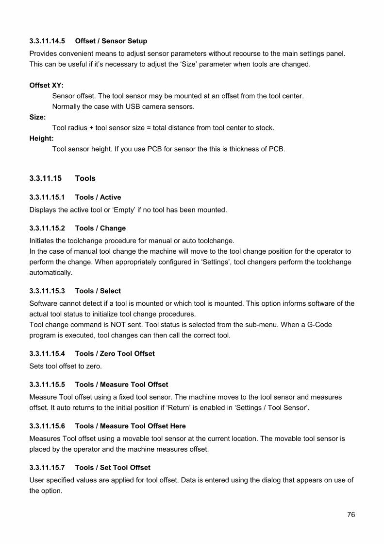
3.3.11.17.1 Transformation / Transformation Matrix
Applies matrix based transformation to current G-Code program.
3.3.11.17.2 Transformation / Calculate Transformation Matrix
Calculates matrix based transformation for current G-Code program.
77
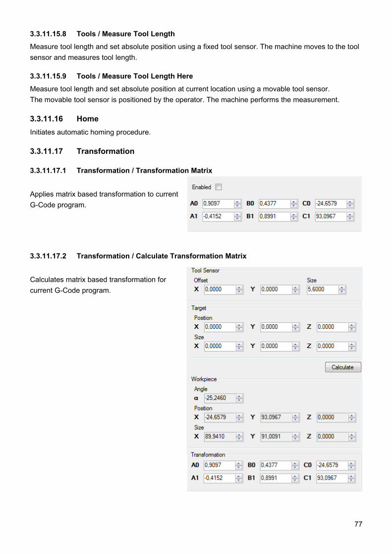
3.3.11.17.3 Transformation / Calculate Matrix From Points
Calculates matrix based transformation for current G-Code program using captured, measured to stored ‘point’s data.
3.3.11.17.4 Transformation / Capture & Measure Points / Measure
Initiates measuring procedure using a ‘movable’ sensor.
Measure Edge X-: Moves the X axis in the positive direction, stops on contact with tool sensor and captures point.
Measure Edge X+: Moves the X axis in the negative direction, stops on contact with tool sensor and captures point.
Measure Edge Y-: Moves the Y axis in the positive direction, stops on contact with tool sensor and captures point.
Measure Edge Y+: Moves the Y axis tin the negative direction, stops on contact with tool sensor and captures point.
78
3.3.11.17.5 Transformation / Capture & Measure Points / Capture
Initiates points capture using a ‘movable’ sensor. USB camera sensors may be used.
Capture Point: Stores the current machine location as an entry in the ‘points’ list.
Capture Point X-: Stores the current machine location as an entry for “Edge X-” in the ‘points’ list.
Capture Point X+: Stores the current machine location as an entry for “Edge X+” in the ‘points’ list.
Capture Point Y-: Stores the current machine location as an entry for “Edge Y-” in the ‘points’ list.
Capture Point Y+: Stores the current machine location as an entry for “Edge Y+” in the ‘points’ list.
3.3.11.17.6 Transformation / Capture & Measure Points / Clear
Clear Points:Clears not edge related points from the ‘points’ list.
Clear Points X-: Clears “Edge X-” points from the ‘points’ list.
Clear Points X+: Clears “Edge X+” points from the ‘points’ list.
Clear Points Y-: Clears “Edge Y-” points from the ‘points’ list.
Clear Points Y+: Clears “Edge Y+” points from the ‘points’ list.
Clear All Points: Clears all stored points from the ‘points’ list.
3.3.11.17.7 Transformation / Capture & Measure Points / Load Points
Loads a set of previously saved transformation matrix points data.
3.3.11.17.8 Transformation / Capture & Measure Points / Save Points
Saves the active transformation matrix points data to file.
79
3.3.11.17.9 Transformation / Capture & Measure Points / Show Camera
‘Show Camera’ opens camera dialog. It’s designed to display the view visible to a USB web-cam, mounted alongside the spindle, looking down on the workpiece.
The large cross-hair marker in the center of the view is used for precise ‘targeting’ of points on the stock, for measurement or capture purposes.Available USB web-cams are listed in a drop-down in the center of the panel. Depending on attached hardware, options to use camera filters may also be shown. CNC USB software provides adjustment, so the basic web-cam option is selected.
On selection of valid hardware, the display updates to show the camera view. ‘Config’ becomes active, giving access to further adjustment options.
Tool sensor use does not require sophisticated hardware. Basic web-cam hardware is suitable. It is much less costly to replace in event of failure or damage.
Camera hardware mounted close to spindles experiences much vibration. Robust construction and the ability to mount hardware securely are the most important considerations when choosing web-cam tool sensors. Camera and camera cable might also be source of electrical interference.
3.3.11.17.10 Transformation / Capture & Measure Points / Sensor
Provides convenient means to adjust sensor parameters without recourse to the main settings panel. This can be useful if it’s necessary to adjust the ‘Size’ parameter when tools are changed.
Sensor Setup / Offset XY: Sensor offset. The tool sensor may be mounted at an offset from the tool center.Normally the case with USB camera sensors.
Sensor Setup / Size: Tool radius + tool sensor size = total distance from tool center to stock.
Sensor Setup / Height: Tool sensor height. If you use PCB for sensor the this is thickness of PCB.
Mark Offset:Temporary stores position for sensor Offset XY calculation.
Read Offset:Reads temporary stored position and calculates Offset XY.
80
3.3.11.18 Soft LimitsUsed to temporarily disable soft limits during machine setup. During setup, correct coordinates are not yet in place. If active, ‘Soft Limits’ may prevent movement when current settings indicate the machine is at it’s limit.
3.3.11.19 FirmwareFirmware management functions for update and verification.
Update: Updates controller firmware with version embedded in software.
Verify: Verifies firmware with the version embedded is current software release.
Reset: Performs controller reset. Same as pressing the controller hardware 'Reset' button.
It is not possible do destroy or damage controller with firmware update. If firmware update fails it is always possible to update it again.
81
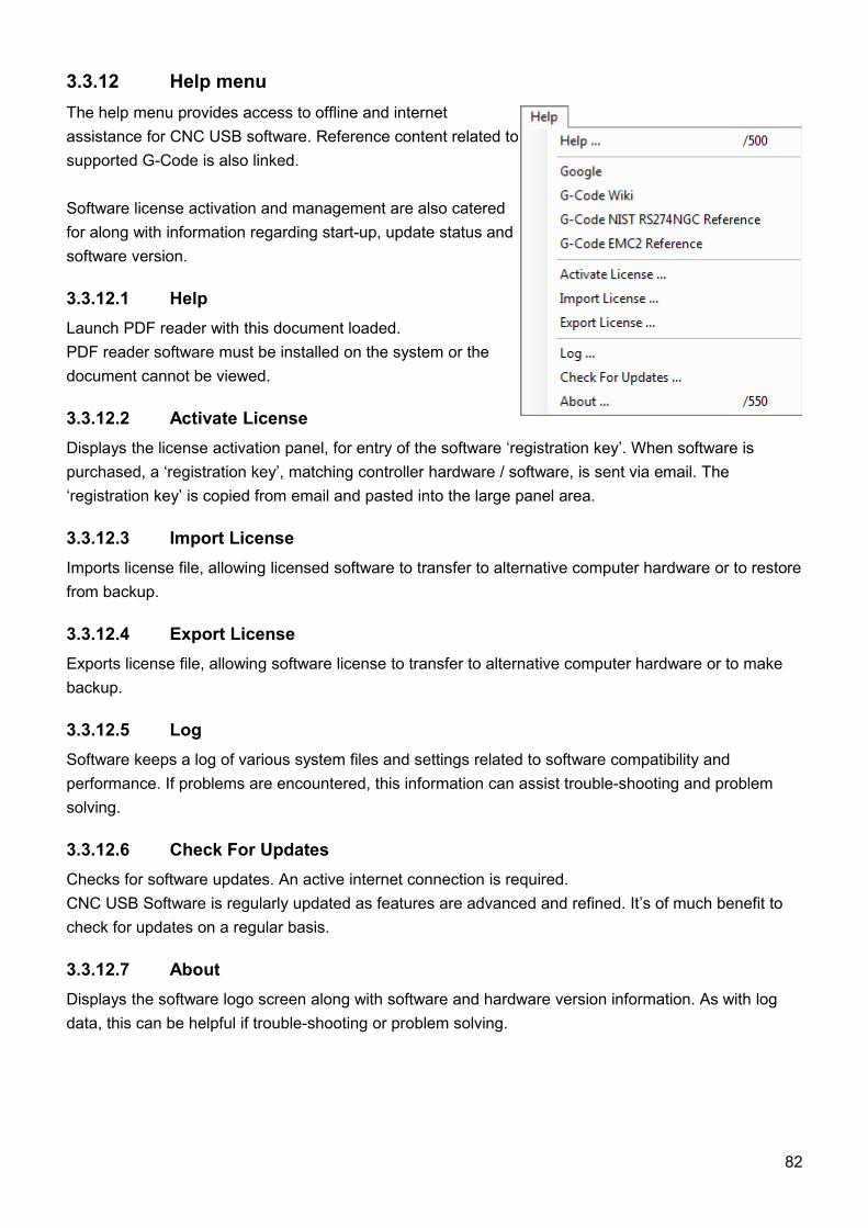
3.3.12 Help menuThe help menu provides access to offline and internet assistance for CNC USB software. Reference content related to supported G-Code is also linked.
Software license activation and management are also catered for along with information regarding start-up, update status and software version.
3.3.12.1 HelpLaunch PDF reader with this document loaded. PDF reader software must be installed on the system or the document cannot be viewed.
3.3.12.2 Activate LicenseDisplays the license activation panel, for entry of the software ‘registration key’. When software is purchased, a ‘registration key’, matching controller hardware / software, is sent via email. The ‘registration key’ is copied from email and pasted into the large panel area.
3.3.12.3 Import LicenseImports license file, allowing licensed software to transfer to alternative computer hardware or to restore from backup.
3.3.12.4 Export LicenseExports license file, allowing software license to transfer to alternative computer hardware or to make backup.
3.3.12.5 LogSoftware keeps a log of various system files and settings related to software compatibility and performance. If problems are encountered, this information can assist trouble-shooting and problem solving.
3.3.12.6 Check For UpdatesChecks for software updates. An active internet connection is required.CNC USB Software is regularly updated as features are advanced and refined. It’s of much benefit to check for updates on a regular basis.
3.3.12.7 AboutDisplays the software logo screen along with software and hardware version information. As with log data, this can be helpful if trouble-shooting or problem solving.
82
3.4 SettingsController software configuration is adjusted using the ‘File ’ menu ‘Settings ’ item. A tabbed panel will
appear. The panel allows setup of all software options and features. Settings allow automation and
integration of many features to provide advanced functions and simplify or speed-up many common
tasks. Required options are dependent on user machinery, ancillary hardware and application.
It’s MOST IMPORTANT that software is appropriately configured before any attempt is made to control
CNC machinery. Failure to do so may result in serious injury or damage to machinery. With unknown or
untested machinery, it’s safer to keep initial motion rates below anticipated maximums. Emergency stop
and limit switch hardware should be configured and functional before higher rate traverse or ‘rapid’
moves are performed.
Settings shown in this section are examples. It’s the users responsibility to ensure safe and appropriate
settings are applied to suit the controlled machine. Mk2 - 9 axis controller settings are used in
examples. Most settings are applicable to other controllers. If model specific settings are required, this
is noted in the text.
Some settings relate to hardware. These might be items like tool sensors, jog keyboards, MPG
Pendants, toolchangers and so forth. If hardware is not available when software is configured, it can be
installed and configured separately. It may be helpful to have hardware in place and operational before
configuring related options. This allows testing or adjustment to determine safe and suitable
parameters. Again, for reasons of safety, this is particularly the case with emergency stop and limit
switch hardware.
83
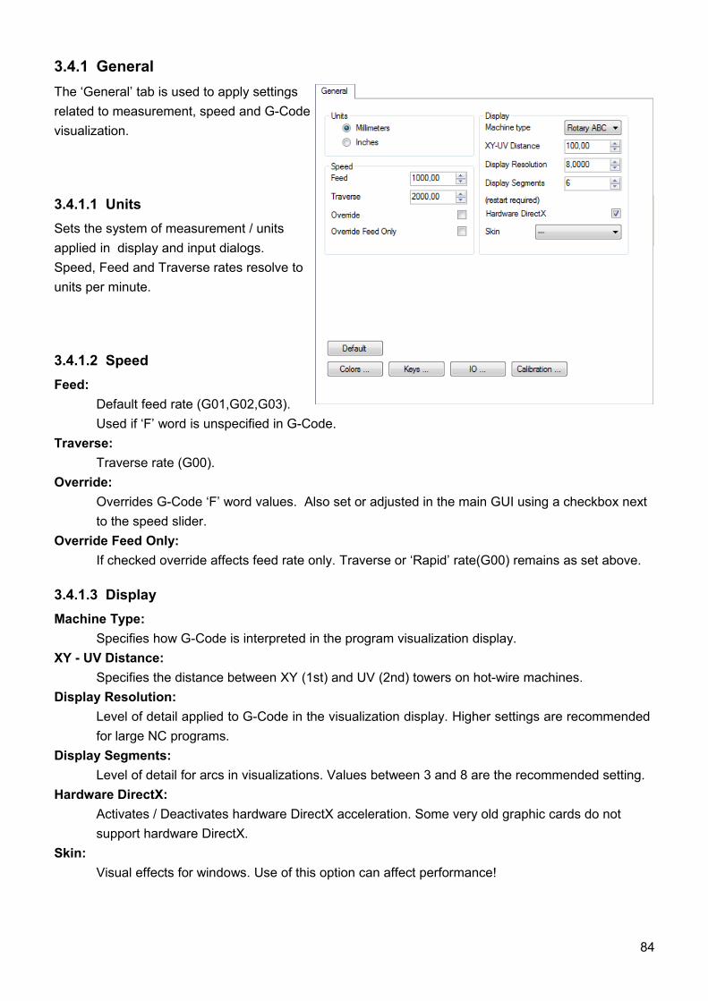
3.4.1 GeneralThe ‘General’ tab is used to apply settingsrelated to measurement, speed and G-Codevisualization.
3.4.1.1 UnitsSets the system of measurement / units applied in display and input dialogs.Speed, Feed and Traverse rates resolve to units per minute.
3.4.1.2 SpeedFeed:
Default feed rate (G01,G02,G03). Used if ‘F’ word is unspecified in G-Code.
Traverse:Traverse rate (G00).
Override:Overrides G-Code ‘F’ word values. Also set or adjusted in the main GUI using a checkbox next to the speed slider.
Override Feed Only:If checked override affects feed rate only. Traverse or ‘Rapid’ rate(G00) remains as set above.
3.4.1.3 DisplayMachine Type:
Specifies how G-Code is interpreted in the program visualization display.XY - UV Distance:
Specifies the distance between XY (1st) and UV (2nd) towers on hot-wire machines.Display Resolution:
Level of detail applied to G-Code in the visualization display. Higher settings are recommended for large NC programs.
Display Segments: Level of detail for arcs in visualizations. Values between 3 and 8 are the recommended setting.
Hardware DirectX: Activates / Deactivates hardware DirectX acceleration. Some very old graphic cards do not support hardware DirectX.
Skin: Visual effects for windows. Use of this option can affect performance!
84
3.4.1.4 Default buttonRestore settings to default values and parameters.
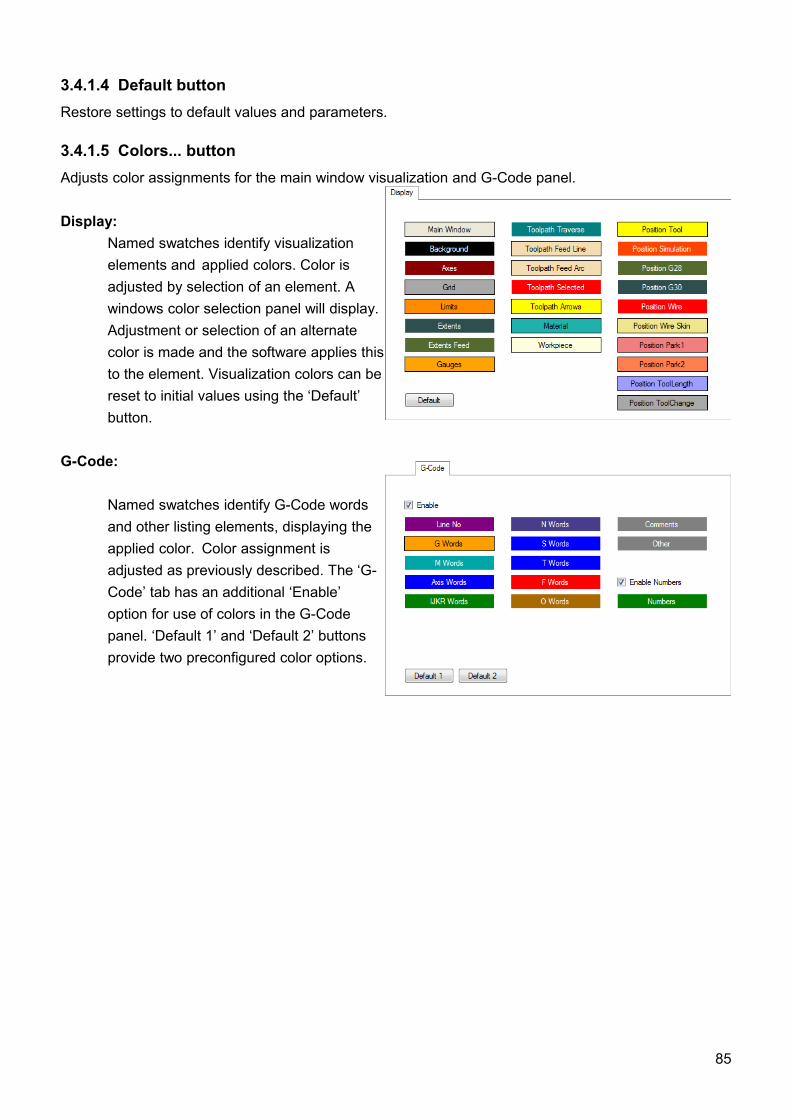
3.4.1.5 Colors... buttonAdjusts color assignments for the main window visualization and G-Code panel.
Display: Named swatches identify visualization elements and applied colors. Color is adjusted by selection of an element. A windows color selection panel will display. Adjustment or selection of an alternate color is made and the software applies this to the element. Visualization colors can be reset to initial values using the ‘Default’ button.
G-Code:
Named swatches identify G-Code words and other listing elements, displaying the applied color. Color assignment is adjusted as previously described. The ‘G-Code’ tab has an additional ‘Enable’ option for use of colors in the G-Code panel. ‘Default 1’ and ‘Default 2’ buttons provide two preconfigured color options.
85
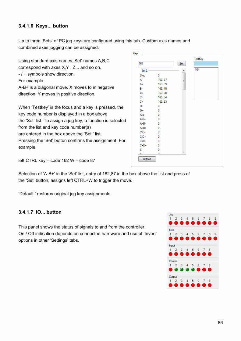
3.4.1.6 Keys... button
Up to three ‘Sets’ of PC jog keys are configured using this tab. Custom axis names andcombined axes jogging can be assigned.
Using standard axis names,‘Set’ names A,B,C correspond with axes X,Y , Z... and so on. - / + symbols show direction. For example:A-B+ is a diagonal move. X moves to in negative direction, Y moves in positive direction.
When ‘Testkey’ is the focus and a key is pressed, the key code number is displayed in a box abovethe ‘Set’ list. To assign a jog key, a function is selected from the list and key code number(s)are entered in the box above the ‘Set ’ list.Pressing the ‘Set’ button confirms the assignment. For example,
left CTRL key = code 162 W = code 87
Selection of ‘A-B+’ in the ‘Set’ list, entry of 162,87 in the box above the list and press ofthe ‘Set’ button, assigns left CTRL+W to trigger the move.
‘Default ’ restores original jog key assignments.
3.4.1.7 IO... button
This panel shows the status of signals to and from the controller. On / Off indication depends on connected hardware and use of ‘Invert’ options in other ‘Settings’ tabs.
86
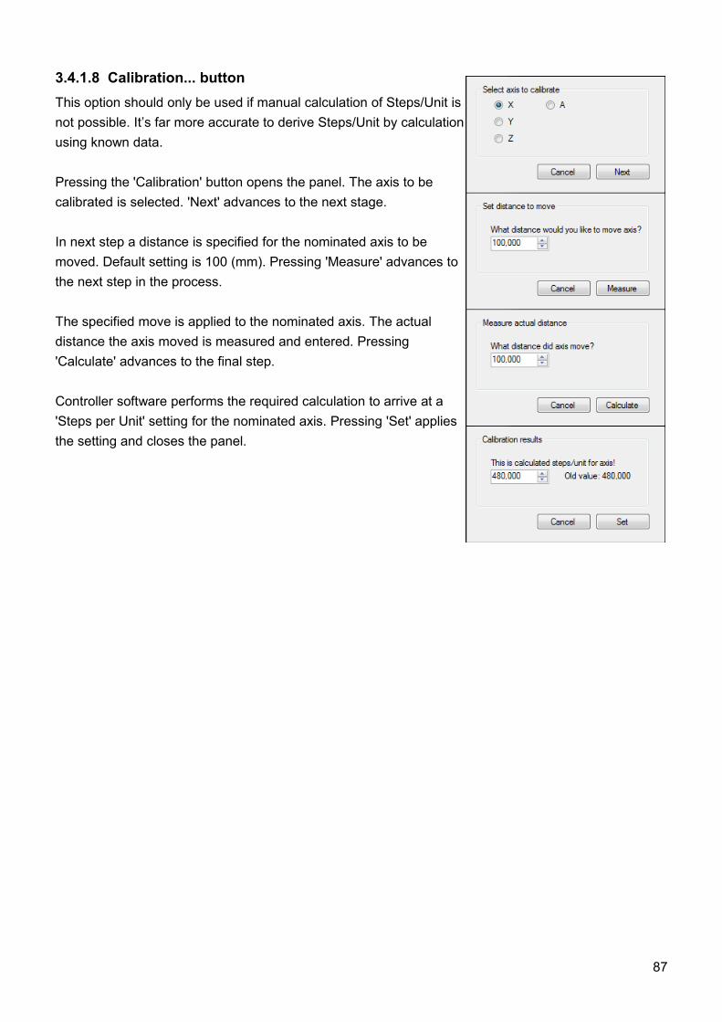
3.4.1.8 Calibration... buttonThis option should only be used if manual calculation of Steps/Unit is not possible. It’s far more accurate to derive Steps/Unit by calculation using known data.
Pressing the 'Calibration' button opens the panel. The axis to be calibrated is selected. 'Next' advances to the next stage.
In next step a distance is specified for the nominated axis to be moved. Default setting is 100 (mm). Pressing 'Measure' advances to the next step in the process.
The specified move is applied to the nominated axis. The actual distance the axis moved is measured and entered. Pressing 'Calculate' advances to the final step.
Controller software performs the required calculation to arrive at a 'Steps per Unit' setting for the nominated axis. Pressing 'Set' applies the setting and closes the panel.
87
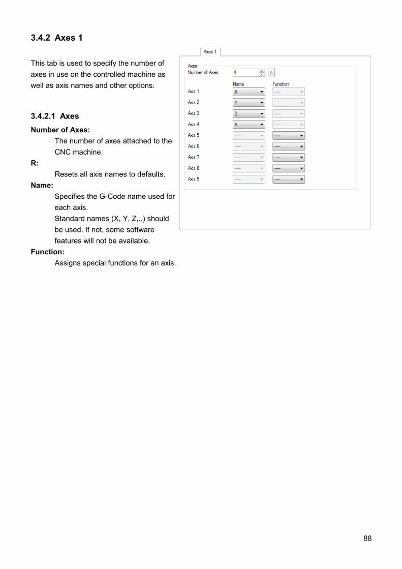
3.4.2 Axes 1
This tab is used to specify the number of axes in use on the controlled machine as well as axis names and other options.
3.4.2.1 AxesNumber of Axes:
The number of axes attached to the CNC machine.
R: Resets all axis names to defaults.
Name: Specifies the G-Code name used for each axis. Standard names (X, Y, Z,..) should be used. If not, some software features will not be available.
Function: Assigns special functions for an axis.
88
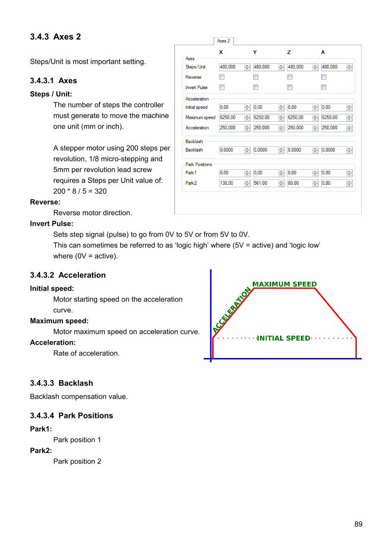
3.4.3 Axes 2
Steps/Unit is most important setting.
3.4.3.1 AxesSteps / Unit:
The number of steps the controller must generate to move the machine one unit (mm or inch).
A stepper motor using 200 steps perrevolution, 1/8 micro-stepping and 5mm per revolution lead screw requires a Steps per Unit value of:200 * 8 / 5 = 320
Reverse: Reverse motor direction.
Invert Pulse:Sets step signal (pulse) to go from 0V to 5V or from 5V to 0V.This can sometimes be referred to as ‘logic high’ where (5V = active) and ‘logic low’ where (0V = active).
3.4.3.2 AccelerationInitial speed:
Motor starting speed on the acceleration curve.
Maximum speed: Motor maximum speed on acceleration curve.
Acceleration: Rate of acceleration.
3.4.3.3 BacklashBacklash compensation value.
3.4.3.4 Park PositionsPark1:
Park position 1Park2:
Park position 2
89
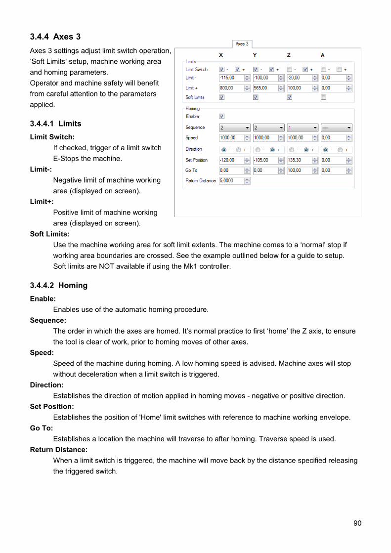
3.4.4 Axes 3Axes 3 settings adjust limit switch operation, ‘Soft Limits’ setup, machine working area and homing parameters. Operator and machine safety will benefit from careful attention to the parameters applied.
3.4.4.1 LimitsLimit Switch:
If checked, trigger of a limit switch E-Stops the machine.
Limit-: Negative limit of machine working area (displayed on screen).
Limit+: Positive limit of machine working area (displayed on screen).
Soft Limits: Use the machine working area for soft limit extents. The machine comes to a ‘normal’ stop if working area boundaries are crossed. See the example outlined below for a guide to setup.Soft limits are NOT available if using the Mk1 controller.
3.4.4.2 HomingEnable:
Enables use of the automatic homing procedure.Sequence:
The order in which the axes are homed. It’s normal practice to first ‘home’ the Z axis, to ensure the tool is clear of work, prior to homing moves of other axes.
Speed:Speed of the machine during homing. A low homing speed is advised. Machine axes will stop without deceleration when a limit switch is triggered.
Direction:Establishes the direction of motion applied in homing moves - negative or positive direction.
Set Position:Establishes the position of 'Home' limit switches with reference to machine working envelope.
Go To:Establishes a location the machine will traverse to after homing. Traverse speed is used.
Return Distance:When a limit switch is triggered, the machine will move back by the distance specified releasing the triggered switch.
90

Example:A machine has two X axis limit switches exactly 500mm apart. To give tolerance of 10mm on each side, the working area is set as ‘Limit- = 0’ and ‘Limit+= 480’. The X axis has absolute value range of -10 mm to +490 mm = 500 mm.
Homing in the positive X direction (‘Direction = +’), the machine triggers a limit switch at location 490 mm. Using ‘Return Distance = 3’, the X axis moves back 3 mm to location 487 mm, releasing the switch.
A ‘Set position ’ value of = 487 is applied. ‘Go To = 0’ initiates a traverse move of 487 mm towards the X axis negative extent, stopping at 0 mm (10 mm from the negative extent limit switch at location -10 mm).
If ‘Soft Limits’ are active, 10 mm tolerance is sufficient for the machine to decelerate to a normal stop before a limit switch is triggered and the machine performs a hard emergency stop.
91
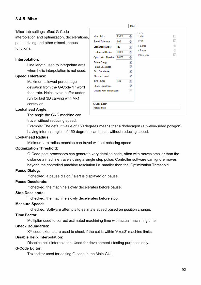
3.4.5 Misc
‘Misc’ tab settings affect G-Code interpolation and optimization, decelerations, pause dialog and other miscellaneous functions.
Interpolation:Line length used to interpolate arcs when helix interpolation is not used.
Speed Tolerance: Maximum allowed percentage deviation from the G-Code ‘F’ word feed rate. Helps avoid buffer under run for fast 3D carving with Mk1 controller.
Lookahead Angle: The angle the CNC machine can travel without reducing speed.Example: The default value of 150 degrees means that a dodecagon (a twelve-sided polygon) having internal angles of 150 degrees, can be cut without reducing speed.
Lookahead Radius: Minimum arc radius machine can travel without reducing speed.
Optimization Threshold:G-Code post-processors can generate very detailed code, often with moves smaller than the distance a machine travels using a single step pulse. Controller software can ignore moves beyond the controlled machine resolution i.e. smaller than the ‘Optimization Threshold’.
Pause Dialog:If checked, a pause dialog / alert is displayed on pause.
Pause Decelerate:If checked, the machine slowly decelerates before pause.
Stop Decelerate:If checked, the machine slowly decelerates before stop.
Measure Speed:If checked, Software attempts to estimate speed based on position change.
Time Factor:Multiplier used to correct estimated machining time with actual machining time.
Check Boundaries:XY code extents are used to check if the cut is within ‘Axes3’ machine limits.
Disable Helix Interpolation:Disables helix interpolation. Used for development / testing purposes only.
G-Code Editor:Text editor used for editing G-code in the Main GUI.
92
3.4.5.1 ExtPinExt pin is only available on Mk1 controller.
Enable: Enables use of the ‘Ext pin’.
Invert:Specifies switch hardware connected to ‘Ext pin’ as being Normally Open (uninverted) or Normally Closed (inverted).
Is E-Stop: Triggering of switch hardware connected to ‘Ext pin’ causes emergency stop.
Is Pause: Triggering of switch hardware connected to ‘Ext pin’ causes pause.
Trigger only:Momentary button switch behavior. If unchecked, press or trigger = ON and release = OFF. If checked, the first press or trigger = ON and the second press or trigger = OFF.
93
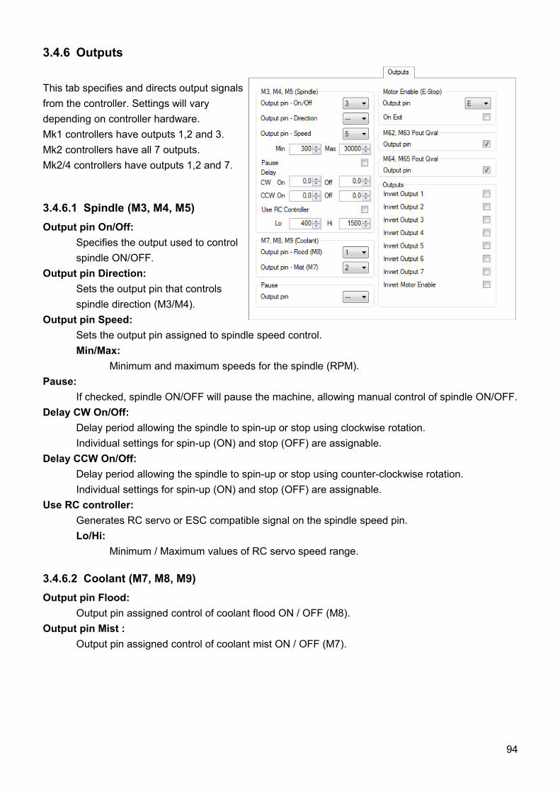
3.4.6 Outputs
This tab specifies and directs output signalsfrom the controller. Settings will vary depending on controller hardware. Mk1 controllers have outputs 1,2 and 3. Mk2 controllers have all 7 outputs.Mk2/4 controllers have outputs 1,2 and 7.
3.4.6.1 Spindle (M3, M4, M5)Output pin On/Off:
Specifies the output used to control spindle ON/OFF.
Output pin Direction: Sets the output pin that controls spindle direction (M3/M4).
Output pin Speed: Sets the output pin assigned to spindle speed control.Min/Max:
Minimum and maximum speeds for the spindle (RPM).Pause:
If checked, spindle ON/OFF will pause the machine, allowing manual control of spindle ON/OFF.Delay CW On/Off:
Delay period allowing the spindle to spin-up or stop using clockwise rotation. Individual settings for spin-up (ON) and stop (OFF) are assignable.
Delay CCW On/Off:Delay period allowing the spindle to spin-up or stop using counter-clockwise rotation. Individual settings for spin-up (ON) and stop (OFF) are assignable.
Use RC controller:Generates RC servo or ESC compatible signal on the spindle speed pin.Lo/Hi:
Minimum / Maximum values of RC servo speed range.
3.4.6.2 Coolant (M7, M8, M9)Output pin Flood:
Output pin assigned control of coolant flood ON / OFF (M8).Output pin Mist :
Output pin assigned control of coolant mist ON / OFF (M7).
94
3.4.6.3 PauseOutput pin:
If an output pin is assigned, ‘Pause’ generates a signal on the specified pin. This can trigger an external device to perform a function. On completion, a signal to a controller input pin can resume NC program execution.
3.4.6.4 Motor EnableOutput pin:
If set, an enable signal is sent to the assigned pin. Mk1 controllers send the signal to OUT3 (see Hardware section of manual). Mk2 and Mk2/4 have dedicated ‘ENABLE’ pins on MOTOR connectors.
On Exit:Safety feature to send an E-Stop signal on shutdown of the software.
3.4.6.5 M62, M63, M64, M65Output pin:
If enabled NC programs can use M62, M63, M64 or M63 codes to control outputs. Code structure is M6x Px Qx. P selects the output, Q determines the value sent.
3.4.6.6 Invert OutputInvert:
Select positive or negative logic (similar to NO/NC).
95
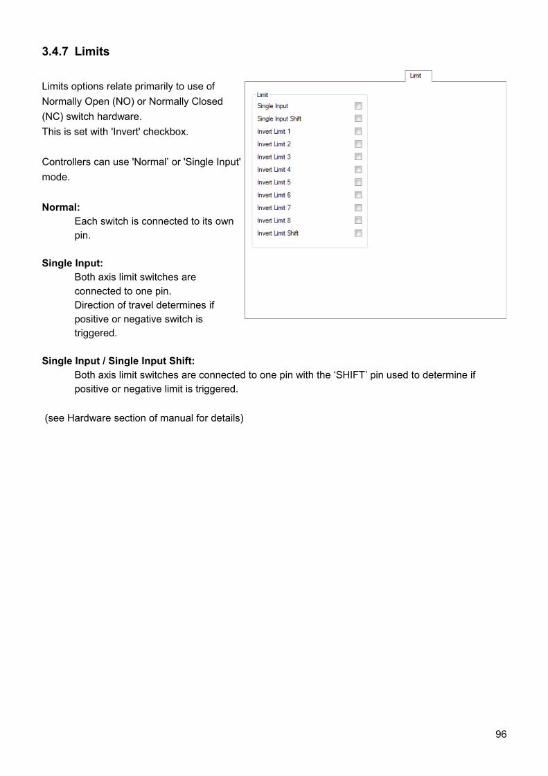
3.4.7 Limits
Limits options relate primarily to use of Normally Open (NO) or Normally Closed (NC) switch hardware. This is set with 'Invert' checkbox.
Controllers can use 'Normal’ or 'Single Input'mode.
Normal:Each switch is connected to its own pin.
Single Input:Both axis limit switches are connected to one pin. Direction of travel determines if positive or negative switch is triggered.
Single Input / Single Input Shift:Both axis limit switches are connected to one pin with the ‘SHIFT’ pin used to determine if positive or negative limit is triggered.
(see Hardware section of manual for details)
96
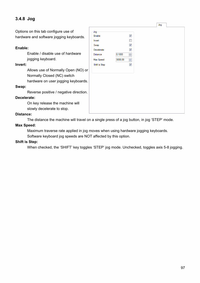
3.4.8 Jog
Options on this tab configure use of hardware and software jogging keyboards.
Enable: Enable / disable use of hardware jogging keyboard.
Invert: Allows use of Normally Open (NO) or Normally Closed (NC) switch hardware on user jogging keyboards.
Swap: Reverse positive / negative direction.
Decelerate: On key release the machine will slowly decelerate to stop.
Distance: The distance the machine will travel on a single press of a jog button, in jog ‘STEP’ mode.
Max Speed: Maximum traverse rate applied in jog moves when using hardware jogging keyboards. Software keyboard jog speeds are NOT affected by this option.
Shift is Step: When checked, the ‘SHIFT’ key toggles ‘STEP’ jog mode. Unchecked, toggles axis 5-8 jogging.
97
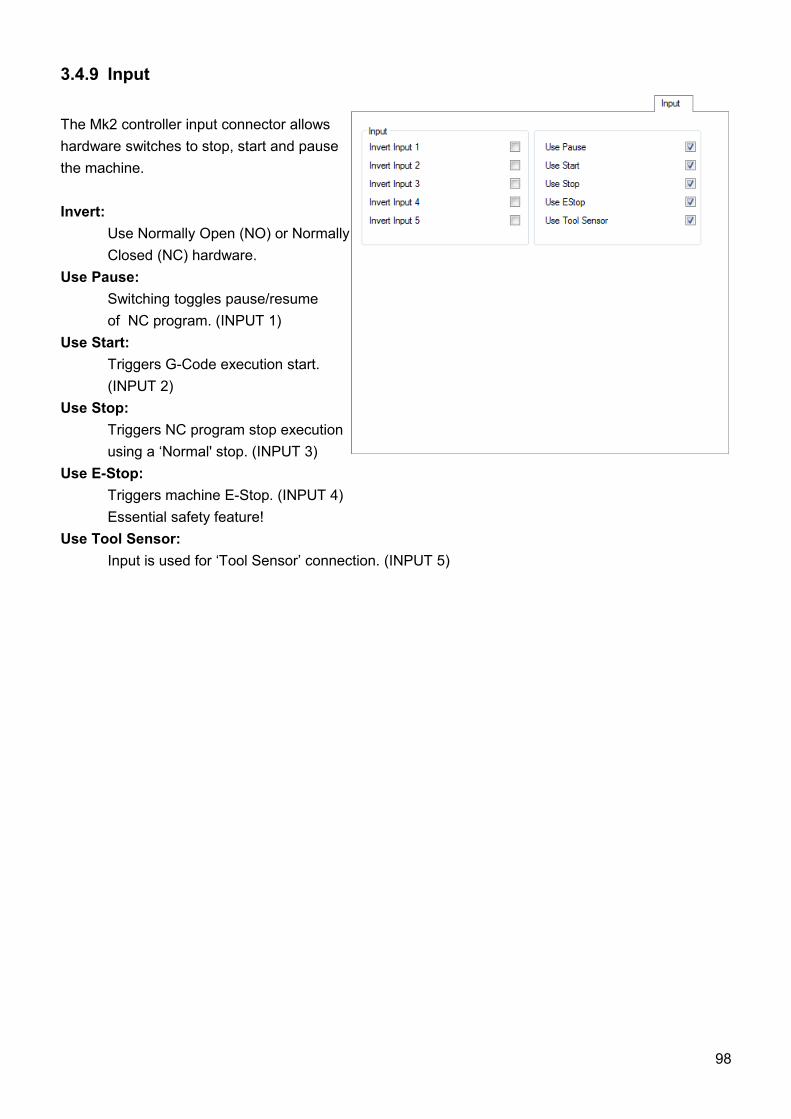
3.4.9 Input
The Mk2 controller input connector allows hardware switches to stop, start and pausethe machine.
Invert: Use Normally Open (NO) or Normally Closed (NC) hardware.
Use Pause: Switching toggles pause/resume of NC program. (INPUT 1)
Use Start: Triggers G-Code execution start. (INPUT 2)
Use Stop: Triggers NC program stop execution
using a ‘Normal' stop. (INPUT 3)Use E-Stop: Triggers machine E-Stop. (INPUT 4)
Essential safety feature! Use Tool Sensor: Input is used for ‘Tool Sensor’ connection. (INPUT 5)
98
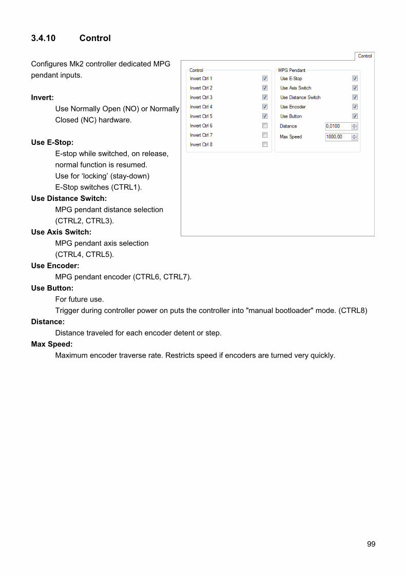
3.4.10 Control
Configures Mk2 controller dedicated MPGpendant inputs.
Invert: Use Normally Open (NO) or Normally Closed (NC) hardware.
Use E-Stop: E-stop while switched, on release, normal function is resumed. Use for ‘locking’ (stay-down)E-Stop switches (CTRL1).
Use Distance Switch: MPG pendant distance selection (CTRL2, CTRL3).
Use Axis Switch: MPG pendant axis selection(CTRL4, CTRL5).
Use Encoder: MPG pendant encoder (CTRL6, CTRL7).
Use Button: For future use.Trigger during controller power on puts the controller into "manual bootloader" mode. (CTRL8)
Distance: Distance traveled for each encoder detent or step.
Max Speed: Maximum encoder traverse rate. Restricts speed if encoders are turned very quickly.
99
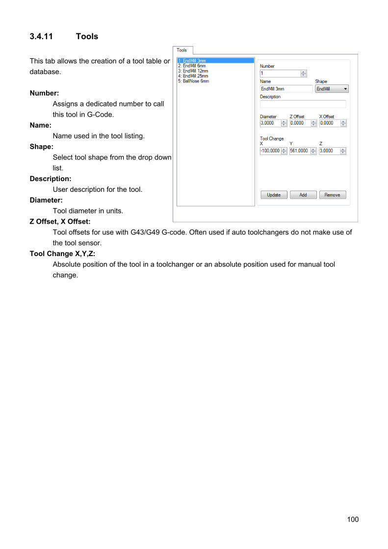
3.4.11 Tools
This tab allows the creation of a tool table ordatabase.
Number: Assigns a dedicated number to call this tool in G-Code.
Name: Name used in the tool listing.
Shape: Select tool shape from the drop down list.
Description: User description for the tool.
Diameter: Tool diameter in units.
Z Offset, X Offset: Tool offsets for use with G43/G49 G-code. Often used if auto toolchangers do not make use of the tool sensor.
Tool Change X,Y,Z: Absolute position of the tool in a toolchanger or an absolute position used for manual tool change.
100
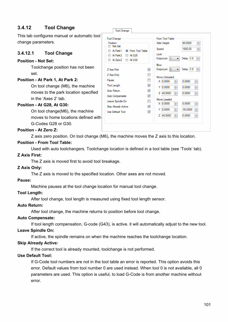
3.4.12 Tool ChangeThis tab configures manual or automatic toolchange parameters.
3.4.12.1 Tool ChangePosition - Not Set:
Toolchange position has not been set.
Position - At Park 1, At Park 2:On tool change (M6), the machine moves to the park location specified in the ‘Axes 2’ tab.
Position - At G28, At G30: On tool change(M6), the machine moves to home locations defined with G-Codes G28 or G30.
Position - At Zero Z:Z axis zero position. On tool change (M6), the machine moves the Z axis to this location.
Position - From Tool Table:Used with auto toolchangers. Toolchange location is defined in a tool table (see ‘Tools’ tab).
Z Axis First:The Z axis is moved first to avoid tool breakage.
Z Axis Only:The Z axis is moved to the specified location. Other axes are not moved.
Pause: Machine pauses at the tool change location for manual tool change.
Tool Length: After tool change, tool length is measured using fixed tool length sensor.
Auto Return: After tool change, the machine returns to position before tool change.
Auto Compensate: If tool length compensation, G-code (G43), is active. it will automatically adjust to the new tool.
Leave Spindle On: If active, the spindle remains on when the machine reaches the toolchange location.
Skip Already Active: If the correct tool is already mounted, toolchange is not performed.
Use Default Tool: If G-Code tool numbers are not in the tool table an error is reported. This option avoids this error. Default values from tool number 0 are used instead. When tool 0 is not available, all 0 parameters are used. This option is useful, to load G-Code is from another machine without error.
101
3.4.12.2 From Tool TableThese options are used if ‘Position ’ is set to ‘From Tool Table ’. See the example below for a detailed description of automatic toolchange.
Safe Height: The Z axis value applied during the move to toolchange position.
Speed: The speed rate applied for the move to toolchange position. Traverse rate speed is used for other moves.
Lock: The output used to send a ‘Lock’ signal to external devices. Delay time to complete ‘Lock’ can be specified.
Blow:The output used to send a ‘Blow’ signal to external devices. Delay time to complete ‘Blow’ can be specified.
Move Unloaded: Parameters controlling a lead in/out offset move when no tool is loaded. Two offsets moves are available.
Move Loaded: Parameters controlling a lead in/out offset move when a tool is loaded.Two offsets moves are available.
Example:Setup of auto toolchanger options requires a little care to begin with, for reasons of operator safetyand avoidance of damage. An appreciation of machine function in this process is helpful. Theprocess is outlined below.
Initial state - no tool is loaded.
Step 1 - Machine moves ‘Z Axis First’ to ‘Safe Height ’. It moves at maximum traverse rate. ‘Leave Spindle On ’ is unchecked, so the spindle will stop. If spindle stop/start is controlled manually, the ‘Pause ’ option allows the spindle to be stopped.
Step 2 - Using ‘Safe Height’ value for the Z axis, the machine traverses in XY to the ‘Tool Change’ location defined in the tooltable for tool 1. No tool has yet been loaded so a ‘Move unloaded’ lead in offset can be applied. Zero, one or two-move lead-ins are available. The Z-Axis will then move down.
Step 3 - Using designated outputs, the controller sends ‘Lock ’ to unlock the collet and ‘Blow’ to clear any debris. A short delay is used to allow the cycle to complete ‘Blow ’.
Step 4 - The machine moves to the ‘Tool Change ’ location using ‘Speed’ ’ rate. The collet engages the tool.
102
Step 5 - Using designated outputs, the controller sends ‘Lock’ to grip the tool and ‘Blow’ to clear any debris. A short delay is used to allow the cycle to complete ‘Blow’.
Step 6 - The machine will move at ‘Speed’ rate to the ‘Tool Change’ location defined in the tool table for tool 1. A tool is now mounted, so a ‘Move loaded’ lead in offset can be applied. Zero, one or two-move lead-ins are available.
Step 7 - If required, automatic tool-length procedure can be inserted into the process at this stage, by use of the ‘Tool Length’ option. If so, tool length will be determined. The machine will move to the tool sensor and measure the tool.
Step 8 - The machine will ‘Auto return’ to it’s initial position using ‘Safe Height’ Z axis location and traverse rate.
Step 9 - If it was stopped at Step1, the machine will start the spindle. If spindle stop/start is controlled manually, a ‘Pause’ option will allow the spindle to be started.
Step 10 - The Z axis moves down to the initial position to engage the tool with the stock and cutting commences.
When use of the mounted tool is complete, the cycle is repeated. As a tool is now loaded, it needs to be unloaded first. Tool unloading is very similar to loading, the order of operations is reversed.
• The Z axis moves to safe Z height, spindle stops.• The machine traverses to tool 1 toolchange position.• The Z axis moves down to release the tool using a ‘Move loaded’ lead in offset.• ‘Lock’ and ‘Blow’ release the tool and clear debris.
The machine then moves at ‘Speed’ rate, using ‘Safe Height’ Z value to tool X tool change position and the load cycle repeats from Step 2.
103
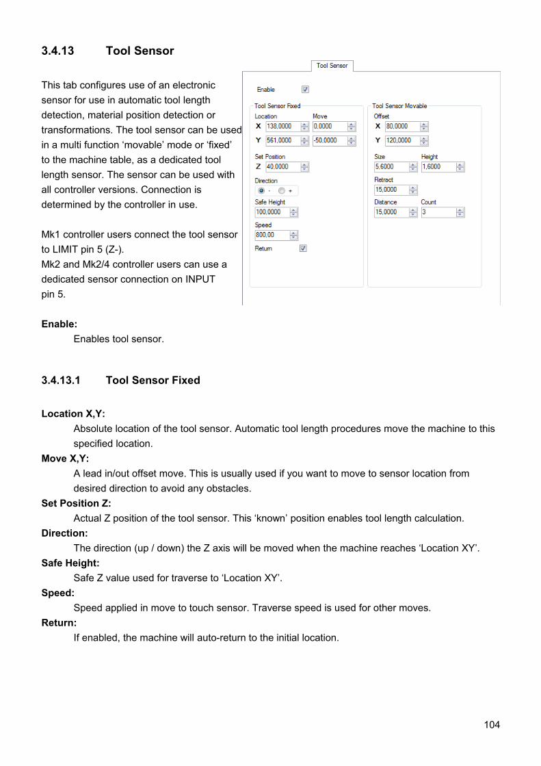
3.4.13 Tool Sensor
This tab configures use of an electronic sensor for use in automatic tool length detection, material position detection or transformations. The tool sensor can be used in a multi function ‘movable’ mode or ‘fixed’ to the machine table, as a dedicated tool length sensor. The sensor can be used with all controller versions. Connection is determined by the controller in use.
Mk1 controller users connect the tool sensor to LIMIT pin 5 (Z-). Mk2 and Mk2/4 controller users can use a dedicated sensor connection on INPUT pin 5.
Enable: Enables tool sensor.
3.4.13.1 Tool Sensor Fixed
Location X,Y: Absolute location of the tool sensor. Automatic tool length procedures move the machine to this specified location.
Move X,Y: A lead in/out offset move. This is usually used if you want to move to sensor location from desired direction to avoid any obstacles.
Set Position Z:Actual Z position of the tool sensor. This ‘known’ position enables tool length calculation.
Direction:The direction (up / down) the Z axis will be moved when the machine reaches ‘Location XY’.
Safe Height: Safe Z value used for traverse to ‘Location XY’.
Speed: Speed applied in move to touch sensor. Traverse speed is used for other moves.
Return: If enabled, the machine will auto-return to the initial location.
104
3.4.13.2 Tool Sensor Movable
Offset X,Y: Sensor offset. Sometimes the sensor is mounted at an offset from tool center. This is usually the case with a USB camera sensor.
Size: Total distance from tool center to stock when sensor is triggered. Example:If the tool sensor is a simple piece of PCB of thickness 1.6mm and tool radius is 4mm (8mm diameter), ‘Size’ value = 1.6 + 4 = 5.6mm
Height: If the tool sensor is a simple piece of PCB of thickness 1.6mm, Height = 1.6mm
Retract:Additional distance that machine moves back after touching sensor.
Distance: The distance between measured points when the tool sensor is used for ‘edge measuring’ for use with transformation features.
Count: The number of measured points used for ‘edge measuring’.
105
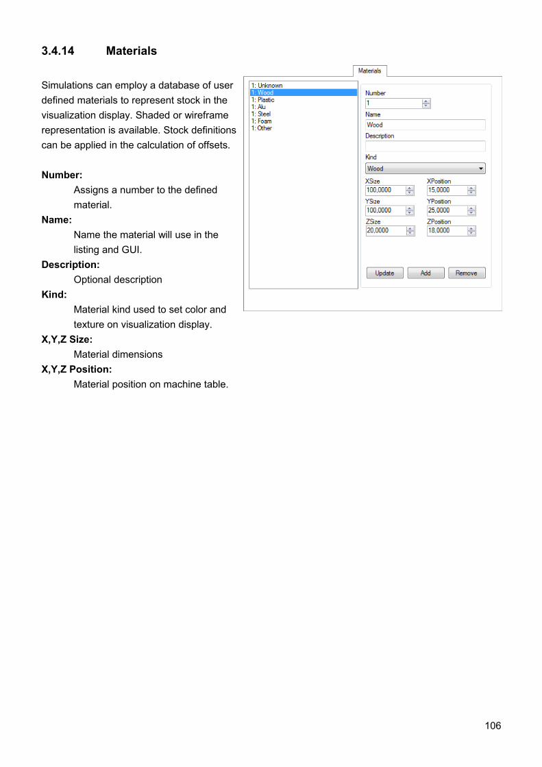
3.4.14 Materials
Simulations can employ a database of user defined materials to represent stock in the visualization display. Shaded or wireframe representation is available. Stock definitions can be applied in the calculation of offsets.
Number: Assigns a number to the defined material.
Name: Name the material will use in the listing and GUI.
Description: Optional description
Kind:Material kind used to set color and texture on visualization display.
X,Y,Z Size: Material dimensions
X,Y,Z Position: Material position on machine table.
106
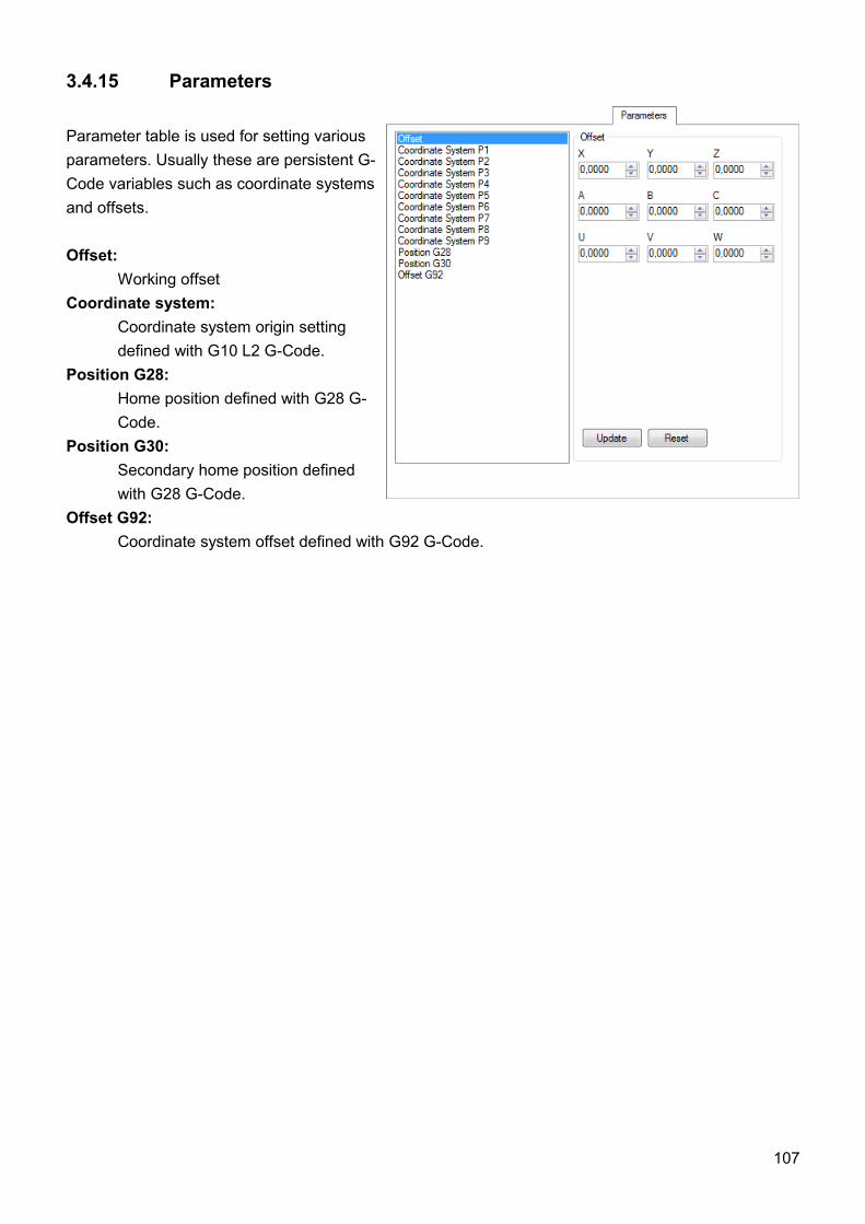
3.4.15 Parameters
Parameter table is used for setting various parameters. Usually these are persistent G-Code variables such as coordinate systems and offsets.
Offset:Working offset
Coordinate system:Coordinate system origin setting defined with G10 L2 G-Code.
Position G28:Home position defined with G28 G-Code.
Position G30:Secondary home position defined with G28 G-Code.
Offset G92:Coordinate system offset defined with G92 G-Code.
107
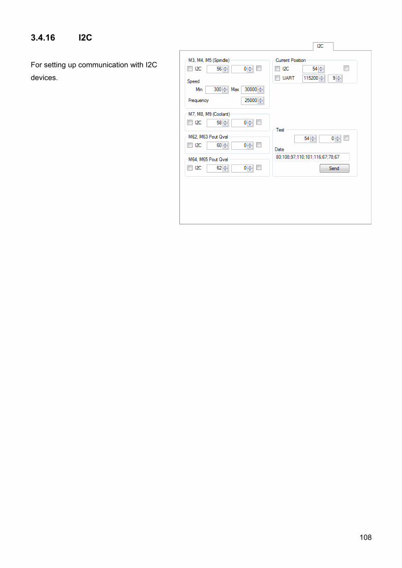
3.4.16 I2C
For setting up communication with I2C
devices.
108
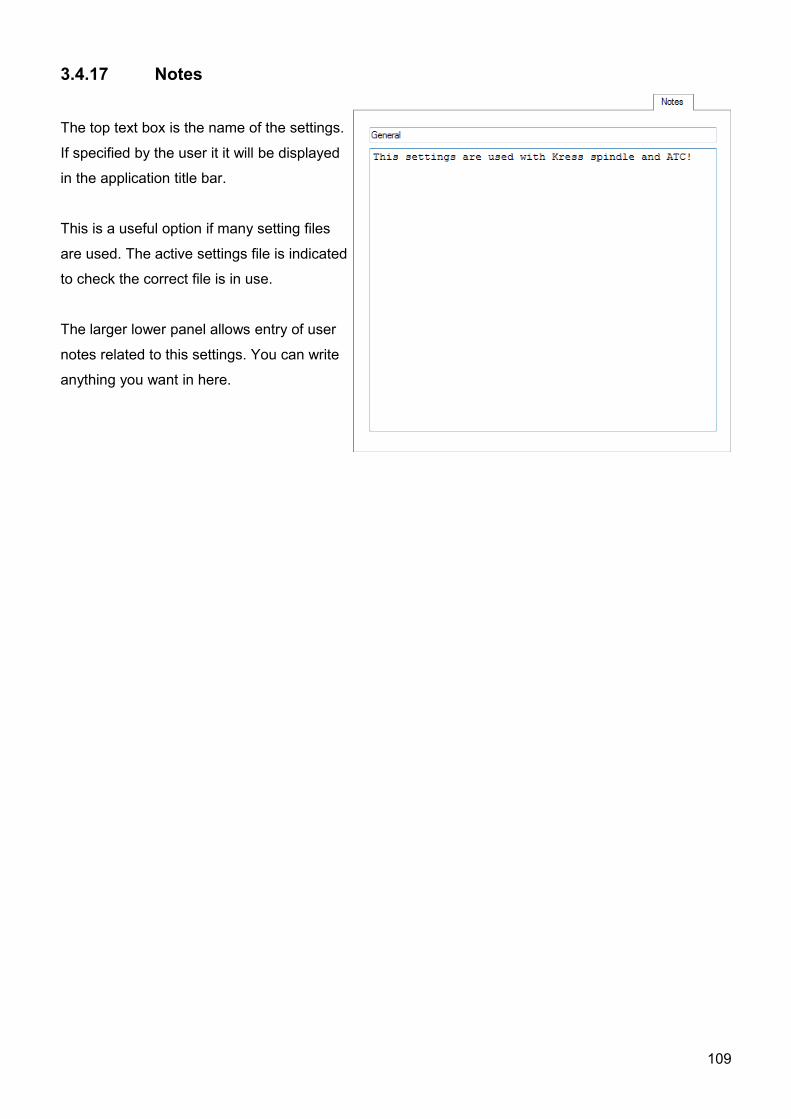
3.4.17 Notes
The top text box is the name of the settings.
If specified by the user it it will be displayed
in the application title bar.
This is a useful option if many setting files
are used. The active settings file is indicated
to check the correct file is in use.
The larger lower panel allows entry of user
notes related to this settings. You can write
anything you want in here.
109
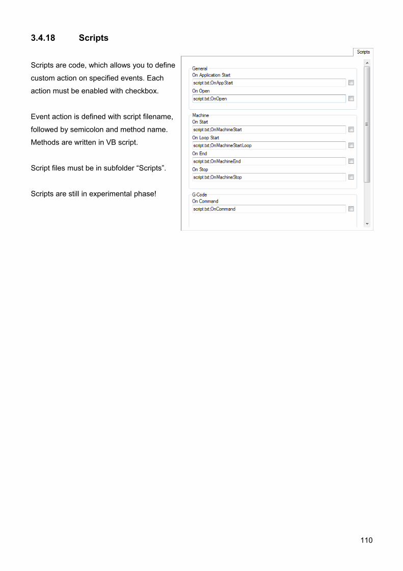
3.4.18 Scripts
Scripts are code, which allows you to define
custom action on specified events. Each
action must be enabled with checkbox.
Event action is defined with script filename,
followed by semicolon and method name.
Methods are written in VB script.
Script files must be in subfolder “Scripts”.
Scripts are still in experimental phase!
110
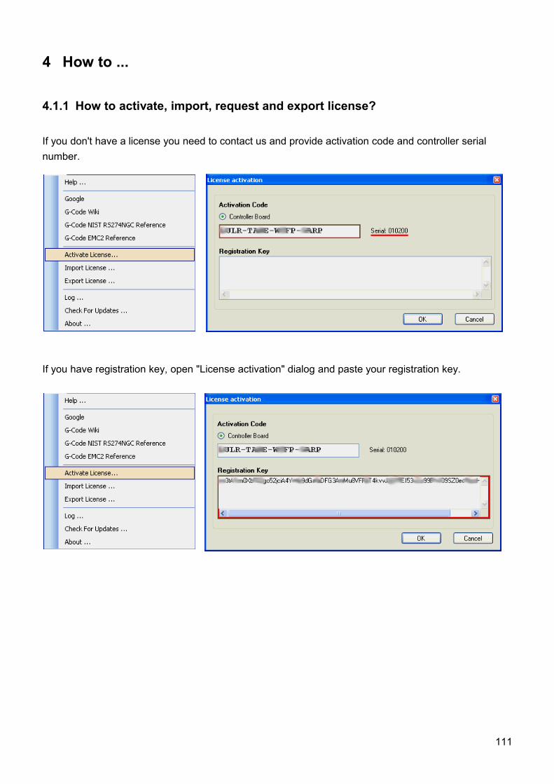
4 How to ...
4.1.1 How to activate, import, request and export license?
If you don't have a license you need to contact us and provide activation code and controller serial number.
If you have registration key, open "License activation" dialog and paste your registration key.
111
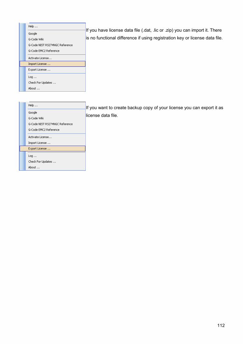
If you have license data file (.dat, .lic or .zip) you can import it. There
is no functional difference if using registration key or license data file.
If you want to create backup copy of your license you can export it as
license data file.
112
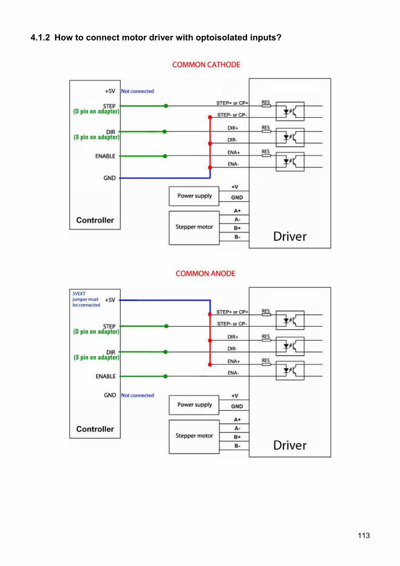
4.1.2 How to connect motor driver with optoisolated inputs?
113
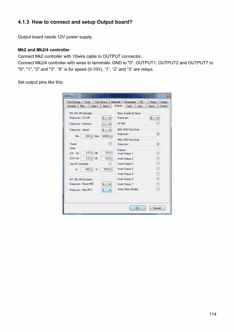
4.1.3 How to connect and setup Output board?
Output board needs 12V power supply.
Mk2 and Mk2/4 controllerConnect Mk2 controller with 10wire cable to OUTPUT connector. Connect Mk2/4 controller with wires to terminals: GND to "0", OUTPUT1, OUTPUT2 and OUTPUT7 to "S", "1", "2" and "3". “S” is for speed (0-10V), “1”, “2” and “3” are relays.
Set output pins like this:
114
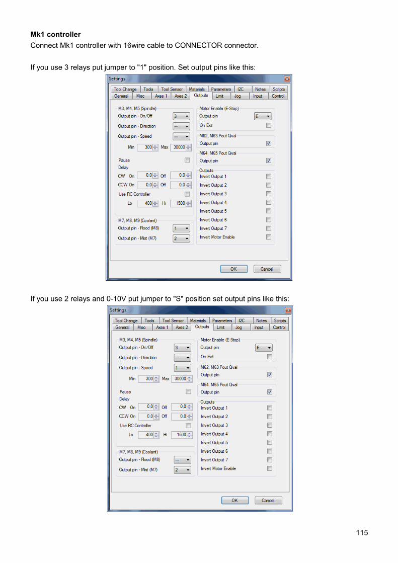
Mk1 controllerConnect Mk1 controller with 16wire cable to CONNECTOR connector.
If you use 3 relays put jumper to "1" position. Set output pins like this:
If you use 2 relays and 0-10V put jumper to "S" position set output pins like this:
115
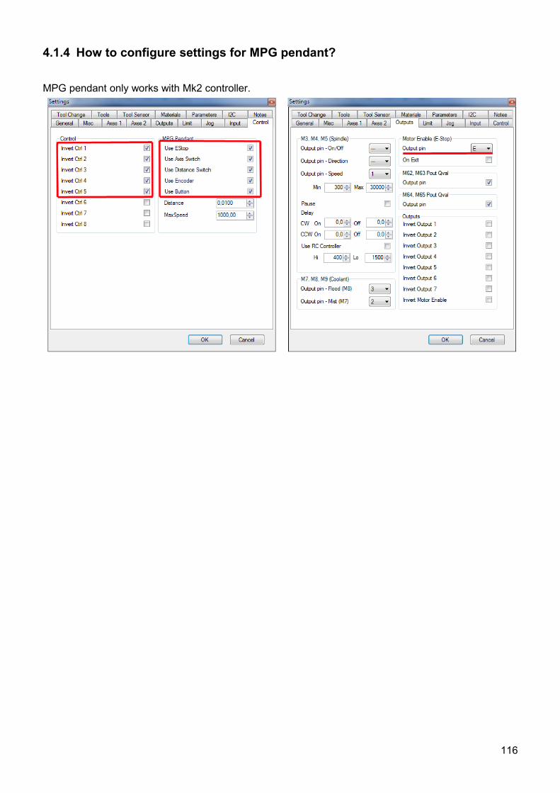
4.1.4 How to configure settings for MPG pendant?
MPG pendant only works with Mk2 controller.
116
5 G-CodeG-code interpreter used by CNC USB controller is implemented according to National Institute of
Standards and Technology RS274NGC Interpreter - Version 3 specification.
Full documentation of RS274NGC is available at web page:
http://www.isd.mel.nist.gov/personnel/kramer/pubs/RS274NGC_3.web/RS274NGC_3TOC.html
5.1 OverviewThe RS274/NGC language is based on lines of code. Each line (also called a "block") may include commands to a machining center to do several different things. Lines of code may be collected in a file to make a program.
A typical line of code consists of an optional line number at the beginning followed by one or more "words." A word consists of a letter followed by a number (or something that evaluates to a number). A word may either give a command or provide an argument to a command. For example, "G1 X3" is a valid line of code with two words. "G1" is a command meaning "move in a straight line at the programmed feed rate," and "X3" provides an argument value (the value of X should be 3 at the end of the move). Most RS274/NGC commands start with either G or M (for miscellaneous). The words for these commands are called "G codes" and "M codes."
The RS274/NGC language has no indicator for the start of a program. The Interpreter, however, deals with files. A single program may be in a single file, or a program may be spread across several files. A file may demarcated with percents in the following way. The first non-blank line of a file may contain nothing but a percent sign, "%", possibly surrounded by white space, and later in the file (normally at the end of the file) there may be a similar line. Demarcating a file with percents is optional if the file has an M2 or M30 in it, but is required if not. An error will be signaled if a file has a percent line at the beginning but not at the end. The useful contents of a file demarcated by percents stop after the second percent line. Anything after that is ignored.
The RS274/NGC language has two commands (M2 or M30), either of which ends a program. A program may end before the end of a file. Lines of a file that occur after the end of a program are not to be executed.
5.2 Format of a LineA permissible line of input RS274/NGC code consists of the following, in order, with the restriction that there is a maximum (currently 256) to the number of characters allowed on a line.
1. an optional block delete character, which is a slash "/" . 2. an optional line number. 3. any number of words, parameter settings, and comments. 4. an end of line marker (carriage return or line feed or both).
Any input not explicitly allowed is illegal and will cause the Interpreter to signal an error.
117
Spaces and tabs are allowed anywhere on a line of code and do not change the meaning of the line, except inside comments. This makes some strange-looking input legal. The line "g0x +0. 12 34y 7" is equivalent to "g0 x+0.1234 y7", for example.
Blank lines are allowed in the input. They are to be ignored.
Input is case insensitive, except in comments. Any letter outside a comment may be in upper or lower case without changing the meaning of a line.
5.3 Line Number A line number is the letter N followed by an integer (with no sign) between 0 and 99999 written with no more than five digits (000009 is not OK, for example). Line numbers may be repeated or used out of order, although normal practice is to avoid such usage. Line numbers may also be skipped, and that is normal practice. A line number is not required to be used, but must be in the proper place if used.
5.4 Word A word is a letter other than N followed by a real value.
Words may begin with any of the letters shown below. Several letters (I, J, K, L, P, R) may have different meanings in different contexts. Permitted letters are:A, B, C, D, F, G, H, I, J, K, L, M, N, P, Q, R, S, T, X, Y, Z
5.5 NumberA real value is some collection of characters that can be processed to come up with a number. A real value may be an explicit number (such as 341 or -0.8807), a parameter value, an expression, or a unary operation value. Definitions of these follow immediately. Processing characters to come up with a number is called "evaluating". An explicit number evaluates to itself.
The following rules are used for (explicit) numbers. In these rules a digit is a single character between 0 and 9.
A number consists of an optional plus or minus sign, followed by zero to many digits, followed, possibly, by one decimal point, followed by zero to many digits - provided that there is at least one digit somewhere in the number.
There are two kinds of numbers: integers and decimals. An integer does not have a decimal point in it, a decimal does.
Numbers may have any number of digits, subject to the limitation on line length. Only about seventeen significant figures will be retained, however (enough for all known applications).
118
A non-zero number with no sign as the first character is assumed to be positive.
Notice that initial (before the decimal point and the first non-zero digit) and trailing (after the decimal point and the last non-zero digit) zeros are allowed but not required. A number written with initial or trailing zeros will have the same value when it is read as if the extra zeros were not there.
Numbers used for specific purposes in RS274/NGC are often restricted to some finite set of values or some to some range of values. In many uses, decimal numbers must be close to integers; this includes the values of indexes (for parameters and carousel slot numbers, for example), M codes, and G codes multiplied by ten. A decimal number which is supposed be close to an integer is considered close enough if it is within 0.0001 of an integer.
5.6 Parameters A parameter value is the pound character # followed by a real value. The real value must evaluate to an integer between 1 and 5399. The integer is a parameter number, and the value of the parameter value is whatever number is stored in the numbered parameter. Parameters can be used as variables.
The # character takes precedence over other operations, so that, for example, "#1+2" means the number found by adding 2 to the value of parameter 1, not the value found in parameter 3. Of course, #[1+2] does mean the value found in parameter 3. The # character may be repeated; for example ##2 means the value of the parameter whose index is the (integer) value of parameter 2.
A parameter setting is the following four items one after the other: (1) a pound character #, (2) a real value which evaluates to an integer between 1 and 5399, (3) an equal sign =, and (4) a real value. For example "#3 = 15" is a parameter setting meaning "set parameter 3 to 15."
A parameter setting does not take effect until after all parameter values on the same line have been found. For example, if parameter 3 has been previously set to 15 and the line "#3=6 G1 x#3" is interpreted, a straight move to a point where x equals 15 will occur and the value of parameter 3 will be 6.
5.7 Expressions and Binary OperationsAn expression is a set of characters starting with a left bracket [ and ending with a balancing right bracket ]. In between the brackets are numbers, parameter values, mathematical operations, and other expressions. An expression may be evaluated to produce a number. The expressions on a line are evaluated when the line is read, before anything on the line is executed. An example of an expression is [ 1 + cos[0] - [#3 ** [4.0/2]]].
Binary operations appear only inside expressions. Nine binary operations are defined. There are four basic mathematical operations: addition (+), subtraction (-), multiplication (*), and division (/). There are three logical operations: non-exclusive or (OR), exclusive or (XOR), and logical and (AND). The eighth
119
operation is the modulus operation (MOD). The ninth operation is the "power" operation (**) of raising the number on the left of the operation to the power on the right.
The binary operations are divided into three groups. The first group is: power. The second group is: multiplication, division, and modulus. The third group is: addition, subtraction, logical non-exclusive or, logical exclusive or, and logical and. If operations are strung together (for example in the expression [2.0 / 3 * 1.5 - 5.5 / 11.0]), operations in the first group are to be performed before operations in the second group and operations in the second group before operations in the third group. If an expression contains more than one operation from the same group (such as the first / and * in the example), the operation on the left is performed first. Thus, the example is equivalent to: [((2.0 / 3) * 1.5) - (5.5 / 11.0)], which simplifies to [1.0 - 0.5], which is 0.5.
The logical operations and modulus are to be performed on any real numbers, not just on integers. The number zero is equivalent to logical false, and any non-zero number is equivalent to logical true.
5.8 Unary Operation ValueA unary operation value is either "ATAN" followed by one expression divided by another expression (for example "ATAN[2]/[1+3]") or any other unary operation name followed by an expression (for example "SIN[90]"). The unary operations are: ABS (absolute value), ACOS (arc cosine), ASIN (arc sine), ATAN (arc tangent), COS (cosine), EXP (e raised to the given power), FIX (round down), FUP (round up), LN (natural logarithm), ROUND (round to the nearest whole number), SIN (sine), SQRT (square root), and TAN (tangent). Arguments to unary operations which take angle measures (COS, SIN, and TAN) are in degrees. Values returned by unary operations which return angle measures (ACOS, ASIN, and ATAN) are also in degrees.
The FIX operation rounds towards the left (less positive or more negative) on a number line, so that FIX[2.8] =2 and FIX[-2.8] = -3, for example. The FUP operation rounds towards the right (more positive or less negative) on a number line; FUP[2.8] = 3 and FUP[-2.8] = -2, for example.
5.9 Comments and MessagesPrintable characters and white space inside parentheses is a comment. A left parenthesis always starts a comment. The comment ends at the first right parenthesis found thereafter. Once a left parenthesis is placed on a line, a matching right parenthesis must appear before the end of the line. Comments may not be nested; it is an error if a left parenthesis is found after the start of a comment and before the end of the comment. Here is an example of a line containing a comment: "G80 M5 (stop motion)". Comments do not cause a machining center to do anything.
A comment contains a message if "MSG," appears after the left parenthesis and before any other printing characters. Variants of "MSG," which include white space and lower case characters are allowed. The rest of the characters before the right parenthesis are considered to be a message. Messages should be displayed on the message display device. Comments not containing messages need not be displayed there.
120
5.10Item RepeatsA line may have any number of G words, but two G words from the same modal group may not appear on the same line.
A line may have zero to four M words. Two M words from the same modal group may not appear on the same line.
For all other legal letters, a line may have only one word beginning with that letter.
If a parameter setting of the same parameter is repeated on a line, "#3=15 #3=6", for example, only the last setting will take effect. It is silly, but not illegal, to set the same parameter twice on the same line.
If more than one comment appears on a line, only the last one will be used; each of the other comments will be read and its format will be checked, but it will be ignored thereafter. It is expected that putting more than one comment on a line will be very rare.
5.11Item OrderThe three types of item whose order may vary on a line (as given at the beginning of this section) are word, parameter setting, and comment. Imagine that these three types of item are divided into three groups by type.
The first group (the words) may be reordered in any way without changing the meaning of the line.
If the second group (the parameter settings) is reordered, there will be no change in the meaning of the line unless the same parameter is set more than once. In this case, only the last setting of the parameter will take effect. For example, after the line "#3=15 #3=6" has been interpreted, the value of parameter 3 will be 6. If the order is reversed to "#3=6 #3=15" and the line is interpreted, the value of parameter 3 will be 15.
If the third group (the comments) contains more than one comment and is reordered, only the last comment will be used.
If each group is kept in order or reordered without changing the meaning of the line, then the three groups may be interleaved in any way without changing the meaning of the line. For example, the line "g40 g1 #3=15 (foo) #4=-7.0" has five items and means exactly the same thing in any of the 120 possible orders (such as "#4=-7.0 g1 #3=15 g40 (foo)") for the five items.
121
5.12Modal and Non-modal modesIn RS274/NGC, many commands cause a machining center to change from one mode to another, and the mode stays active until some other command changes it implicitly or explicitly. Such commands are called "modal". For example, if coolant is turned on, it stays on until it is explicitly turned off. The G codes for motion are also modal. If a G1 (straight move) command is given on one line, for example, it will be executed again on the next line if one or more axis words is available on the line, unless an explicit command is given on that next line using the axis words or canceling motion.
"Non-modal" codes have effect only on the lines on which they occur. For example, G4 (dwell) is non-modal.
5.13Modal GroupsModal commands are arranged in sets called "modal groups", and only one member of a modal group may be in force at any given time. In general, a modal group contains commands for which it is logically impossible for two members to be in effect at the same time - like measure in inches vs. measure in millimeters. A machining center may be in many modes at the same time, with one mode from each modal group being in effect.
The modal groups for G codes are: group 1 = {G0, G1, G2, G3, G38.2, G80, G81, G82, G83, G84, G85, G86, G87, G88, G89} motion group 2 = {G17, G18, G19} plane selection group 3 = {G90, G91} distance mode group 5 = {G93, G94} feed rate mode group 6 = {G20, G21} units group 7 = {G40, G41, G42} cutter radius compensation group 8 = {G43, G49} tool length offset group 10 = {G98, G99} return mode in canned cycles group 12 = {G54, G55, G56, G57, G58, G59, G59.1, G59.2, G59.3} coordinate system selection group 13 = {G61, G61.1, G64} path control mode
The modal groups for M codes are: group 4 = {M0, M1, M2, M30, M60} stopping group 6 = {M6} tool change group 7 = {M3, M4, M5} spindle turning group 8 = {M7, M8, M9} coolant (special case: M7 and M8 may be active at the same time) group 9 = {M48, M49} enable/disable feed and speed override switches
In addition to the above modal groups, there is a group for non-modal G codes: group 0 = {G4, G10, G28, G30, G53, G92, G92.1, G92.2, G92.3}
122
For several modal groups, when a machining center is ready to accept commands, one member of the group must be in effect. There are default settings for these modal groups. When the machining center is turned on or otherwise re-initialized, the default values are automatically in effect.
Group 1, the first group on the table, is a group of G codes for motion. One of these is always in effect. That one is called the current motion mode.
It is an error to put a G-code from group 1 and a G-code from group 0 on the same line if both of them use axis words. If an axis word-using G-code from group 1 is implicitly in effect on a line (by having been activated on an earlier line), and a group 0 G-code that uses axis words appears on the line, the activity of the group 1 G-code is suspended for that line. The axis word-using G-codes from group 0 are G10, G28, G30, and G92.
5.14G - CodesG-codes of the RS274/NGC language are shown and described below.
5.14.1 G00 - Rapid Motion (Linear Motion at Traverse Rate)For rapid linear motion, program G0 X- Y- Z- A- B- C-, where all the axis words are optional, except that at least one must be used. The G0 is optional if the current motion mode is G0. This will produce coordinated linear motion to the destination point at the current traverse rate (or slower if the machine will not go that fast). It is expected that cutting will not take place when a G0 command is executing. It is an error if:
• all axis words are omitted.
If cutter radius compensation is active, the motion will differ from the above.
5.14.2 G01 - Linear Feed (Linear Motion at Feed Rate)For linear motion at feed rate (for cutting or not), program G1 X- Y- Z- A- B- C-, where all the axis words are optional, except that at least one must be used. The G1 is optional if the current motion mode is G1. This will produce coordinated linear motion to the destination point at the current feed rate (or slower if the machine will not go that fast). It is an error if:
• all axis words are omitted.
If cutter radius compensation is active, the motion will differ from the above.
123
5.14.3 G02 - Arc/Helix Feed (CW)5.14.4 G03 - Arc/Helix Feed (CCW) (Arc at Feed Rate)A circular or helical arc is specified using either G2 (clockwise arc) or G3 (counterclockwise arc). The axis of the circle or helix must be parallel to the X, Y, or Z-axis of the machine coordinate system. The axis (or, equivalently, the plane perpendicular to the axis) is selected with G17 (Z-axis, XY-plane), G18 (Y-axis, XZ-plane), or G19 (X-axis, YZ-plane). If the arc is circular, it lies in a plane parallel to the selected plane.
Two formats are allowed for specifying an arc. We will call these the center format and the radius format. In both formats the G2 or G3 is optional if it is the current motion mode.
• Radius Format ArcIn the radius format, the coordinates of the end point of the arc in the selected plane are specified along with the radius of the arc. Program G2 X- Y- Z- A- B- C- R- (or use G3 instead of G2). R is the radius. The axis words are all optional except that at least one of the two words for the axes in the selected plane must be used. The R number is the radius. A positive radius indicates that the arc turns through 180 degrees or less, while a negative radius indicates a turn of 180 degrees to 359.999 degrees. If the arc is helical, the value of the end point of the arc on the coordinate axis parallel to the axis of the helix is also specified. It is an error if:
• both of the axis words for the axes of the selected plane are omitted,• the end point of the arc is the same as the current point.
It is not good practice to program radius format arcs that are nearly full circles or are semicircles (or nearly semicircles) because a small change in the location of the end point will produce a much larger change in the location of the center of the circle (and, hence, the middle of the arc). The magnification effect is large enough that rounding error in a number can produce out-of-tolerance cuts. Nearly full circles are outrageously bad, semicircles (and nearly so) are only very bad. Other size arcs (in the range tiny to 165 degrees or 195 to 345 degrees) are OK.
Here is an example of a radius format command to mill an arc: G17 G2 x 10 y 15 r 20 z 5.
That means to make a clockwise (as viewed from the positive Z-axis) circular or helical arc whose axis is parallel to the Z-axis, ending where X=10, Y=15, and Z=5, with a radius of 20. If the starting value of Z is 5, this is an arc of a circle parallel to the XY-plane; otherwise it is a helical arc.
• Center Format ArcIn the center format, the coordinates of the end point of the arc in the selected plane are specified along with the offsets of the center of the arc from the current location. In this format, it is OK if the end point of the arc is the same as the current point. It is an error if:
124
· when the arc is projected on the selected plane, the distance from the current point to the center differs from the distance from the end point to the center by more than 0.0002 inch (if inches are being used) or 0.002 millimeter (if millimeters are being used).
When the XY-plane is selected, program G2 X- Y- Z- A- B- C- I- J- (or use G3 instead of G2). The axis words are all optional except that at least one of X and Y must be used. I and J are the offsets from the current location (in the X and Y directions, respectively) of the center of the circle. I and J are optional except that at least one of the two must be used. It is an error if:
• X and Y are both omitted,• I and J are both omitted.
When the XZ-plane is selected, program G2 X- Y- Z- A- B- C- I- K- (or use G3 instead of G2). The axis words are all optional except that at least one of X and Z must be used. I and K are the offsets from the current location (in the X and Z directions, respectively) of the center of the circle. I and K are optional except that at least one of the two must be used. It is an error if:
• X and Z are both omitted,• I and K are both omitted.
When the YZ-plane is selected, program G2 X- Y- Z- A- B- C- J- K- (or use G3 instead of G2). The axis words are all optional except that at least one of Y and Z must be used. J and K are the offsets from the current location (in the Y and Z directions, respectively) of the center of the circle. J and K are optional except that at least one of the two must be used.
It is an error if: • Y and Z are both omitted,• J and K are both omitted.
Here is an example of a center format command to mill an arc: G17 G2 X10 Y16 I3 J4 Z9.
That means to make a clockwise (as viewed from the positive z-axis) circular or helical arc whose axis is parallel to the Z-axis, ending where X=10, Y=16, and Z=9, with its center offset in the X direction by 3 units from the current X location and offset in the Y direction by 4 units from the current Y location. If the current location has X=7, Y=7 at the outset, the center will be at X=10, Y=11. If the starting value of Z is 9, this is a circular arc; otherwise it is a helical arc. The radius of this arc would be 5.
In the center format, the radius of the arc is not specified, but it may be found easily as the distance from the center of the circle to either the current point or the end point of the arc.
125
5.14.5 G04 - DwellFor a dwell, program G4 P- . This will keep the axes unmoving for the period of time in seconds specified by the P number. It is an error if:
• the P number is negative.
5.14.6 G7 - Lathe Diameter ModeProgram G7 to enter the diameter mode for axis X on a lathe. When in the diameter mode the X axis moves on a lathe will be 1/2 the distance to the center of the lathe. For example X1 would move the cutter to 0.500” from the center of the lathe thus giving a 1” diameter part.
5.14.7 G8 - Lathe Radius ModeProgram G8 to enter the radius mode for axis X on a lathe. When in Radius mode the X axis moves on a lathe will be the distance from the center. Thus a cut at X1 would result in a part that is 2" in diameter. G8 is default at power up.
5.14.8 G10 L1 - Set Tool TableG10 L1 P[tool number] R[radius] X[offset] Z[offset] Q[orientation]Program a G10 L1 to set a tool table entry from a program. G10 L1 reloads the tool table. It is an error if:
• cutter compensation is on
5.14.9 G10 L2 - Coordinate System Origin SettingYou can set the offsets of the nine program coordinate systems using G10 L2 Pn (n is the number of the coordinate system) with values for the axes in terms of the absolute coordinate system.
To set the coordinate values for the origin of a coordinate system, programG10 L2 P - X- Y- Z- A- B- C-, where the P number must evaluate to an integer in the range 1 to 9 (corresponding to G54 to G59.3) and all axis words are optional. The coordinates of the origin of the coordinate system specified by the P number are reset to the coordinate values given (in terms of the absolute coordinate system). Only those coordinates for which an axis word is included on the line will be reset. It is an error if:
• the P number does not evaluate to an integer in the range 1 to 9.
If origin offsets (made by G92 or G92.3) were in effect before G10 is used, they will continue to be in effect afterwards.
The coordinate system whose origin is set by a G10 command may be active or inactive at the time the G10 is executed.
126
Example: G10 L2 P1 x 3.5 y 17.2 sets the origin of the first coordinate system (the one selected by G54) to a point where X is 3.5 and Y is 17.2 (in absolute coordinates). The Z coordinate of the origin (and the coordinates for any rotational axes) are whatever those coordinates of the origin were before the line was executed.
5.14.10 G10 L9 - Set Machine Position Without MoveExamples:G10 L9 P1 X- Y- Z- A- B- C- Machine will set position to coordinates defined with axis wordsG10 L9 P28 Machine will set position to coordinates defined as G28 homeG10 L9 P30 Machine will set position to coordinates defined as G30 homeG10 L9 P92 Machine will set position to coordinates defined as G92 offset
5.14.11 G17 - XY-Plane Selection5.14.12 G18 - XZ-Plane Selection5.14.13 G19 - YZ-Plane SelectionProgram G17 to select the XY-plane.Program G18 to select the XZ-plane.Program G19 to select the YZ-plane.
5.14.14 G20 - Inch System Selection5.14.15 G21 - Millimeter System SelectionProgram G20 to use inches for length units.Program G21 to use millimeters.
It is usually a good idea to program either G20 or G21 near the beginning of a program before any motion occurs, and not to use either one anywhere else in the program. It is the responsibility of the user to be sure all numbers are appropriate for use with the current length units.
5.14.16 G28 - Return to Predefined Position5.14.17 G30 - Return to Predefined PositionTwo predefined positions are defined (by parameters 5161-5166 for G28 and parameters 5181-5186 for G30). The parameter values are in terms of the absolute coordinate system, but are in unspecified length units.
To return to predefined position by way of the programmed position, program G28 X- Y- Z- A- B- C- (or use G30). All axis words are optional. The path is made by a traverse move from the current position to the programmed position, followed by a traverse move to the home position. If no axis words are programmed, the intermediate point is the current point, so only one move is made.
127
5.14.18 G33 - Spindle Synchronized MotionG33 X- Y- Z- K-K - distance per revolution For spindle-synchronized motion in one direction, code G33 X- Y- Z- K- where K gives the distance moved in XYZ for each revolution of the spindle. For instance, if starting at Z=0, G33 Z-1 K.0625 produces a 1 inch motion in Z over 16 revolutions of the spindle. This command might be part of a program to produce a 16TPI thread. Another example in metric, G33 Z-15 K1.5 produces a movement of 15mm while the spindle rotates 10 times for a thread of 1.5mm. Spindle-synchronized motion waits for the spindle index and spindle at speed pins, so multiple passes line up. G33 moves end at the programmed endpoint. G33 could be used to cut tapered threads or a fusee. All the axis words are optional, except that at least one must be used.Note: K follows the drive line described by X- Y- Z-. K is not parallel to the Z axis if X or Y endpoints are used for example when cutting tapered threads.
5.14.19 G40 - Cancel Cutter Radius CompensationTo turn cutter radius compensation off, program G40. It is OK to turn compensation off when it is already off.
5.14.20 G41 - Start Cutter Radius Compensation Left5.14.21 G42 - Start Cutter Radius Compensation RightCutter radius compensation may be performed only if the XY-plane is active.
To turn cutter radius compensation on left (i.e., the cutter stays to the left of the programmed path when the tool radius is positive), program G41 D- . To turn cutter radius compensation on right (i.e., the cutter stays to the right of the programmed path when the tool radius is positive), program G42 D- . The D word is optional; if there is no D word, the radius of the tool currently in the spindle will be used. If used, the D number should normally be the slot number of the tool in the spindle, although this is not required. It is OK for the D number to be zero; a radius value of zero will be used.
It is an error if: • the D number is not an integer, is negative or is larger than the number of carousel slots,• the XY-plane is not active,• cutter radius compensation is commanded to turn on when it is already on.
5.14.22 G43 - Tool Length OffsetTo use a tool length offset, program G43 H-, where the H number is the desired index in the tool table. It is expected that all entries in this table will be positive. The H number should be, but does not have to
128
be, the same as the slot number of the tool currently in the spindle. It is OK for the H number to be zero; an offset value of zero will be used. It is an error if:
• the H number is not an integer, is negative, or is larger than the number of carousel slots.It is OK to program using the same offset already in use. It is also OK to program using no tool length offset if none is currently being used.
5.14.23 G49 - Cancel Tool Length OffsetTo use no tool length offset, program G49.
5.14.24 G53 - Motion in Machine Absolute CoordinatesYou can make straight moves in the absolute machine coordinate system by using G53 with either G0 or G1.
For linear motion to a point expressed in absolute coordinates, program G1 G53 X- Y- Z- A- B- C- (or use G0 instead of G1), where all the axis words are optional, except that at least one must be used. The G0 or G1 is optional if it is the current motion mode. G53 is not modal and must be programmed on each line on which it is intended to be active. This will produce coordinated linear motion to the programmed point. If G1 is active, the speed of motion is the current feed rate (or slower if the machine will not go that fast). If G0 is active, the speed of motion is the current traverse rate (or slower if the machine will not go that fast). It is an error if:
• G53 is used without G0 or G1 being active,• G53 is used while cutter radius compensation is on.
5.14.25 G54 - Use Preset Work Coordinate System 15.14.26 G55 - Use Preset Work Coordinate System 25.14.27 G56 - Use Preset Work Coordinate System 35.14.28 G57 - Use Preset Work Coordinate System 45.14.29 G58 - Use Preset Work Coordinate System 55.14.30 G59 - Use Preset Work Coordinate System 65.14.31 G59.1 - Use Preset Work Coordinate System 75.14.32 G59.2 - Use Preset Work Coordinate System 85.14.33 G59.3 - Use Preset Work Coordinate System 9You can select one of the nine systems by using G54, G55, G56, G57, G58, G59, G59.1, G59.2, or G59.3. It is not possible to select the absolute coordinate system directly.
To select coordinate system 1, program G54, and similarly for other coordinate systems. The system-number-G-code pairs are:
129
(1-G54), (2-G55), (3-G56), (4-G57), (5-G58), (6-G59), (7-G59.1), (8-G59.2), and (9-G59.3). It is an error if:
• one of these G-codes is used while cutter radius compensation is on.
5.14.34 G61 - Set Path Control Mode: Exact Path5.14.35 G61.1 - Set Path Control Mode: Exact Stop5.14.36 G64 - Set Path Control Mode: Continuous(not implemented)Program G61 to put the machining center into exact path mode, G61.1 for exact stop mode, or G64 for continuous mode. It is OK to program for the mode that is already active.
5.14.37 G73 - Drilling Cycle with Chip BreakingThe G73 cycle is intended for deep drilling or milling with chip breaking. The retracts in this cycle cut off any long stringers (which are common when drilling in aluminum). This cycle takes a Q number which represents a "delta" increment along the Z axis.Program G73 X- Y- Z- A- B- C- R- L- Q-
1. Preliminary motion, as described above. 2. Move the Z-axis only at the current feed rate downward by delta or to the Z position, whichever
is less deep. 3. Rapid up a bit.4. Repeat steps 2 and 3 until the Z position is reached at step 2.5. Retract the Z-axis at traverse rate to clear Z.
It is an error if:• the Q number is negative or zero.
5.14.38 G76 - Threading CycleProgram G76 P- Z- I- J- R- K- Q- H- E- L-It is an error if:
• The active plane is not the ZX plane• Other axis words, such as X- or Y-, are specified• The R- degression value is less than 1.0.• All the required words are not specified• P-, J-, K- or H- is negative• E- is greater than half the drive line length
130
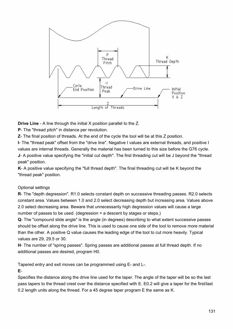
Drive Line - A line through the initial X position parallel to the Z.P- The "thread pitch" in distance per revolution.Z- The final position of threads. At the end of the cycle the tool will be at this Z position.I- The "thread peak" offset from the "drive line". Negative I values are external threads, and positive I values are internal threads. Generally the material has been turned to this size before the G76 cycle.J- A positive value specifying the "initial cut depth". The first threading cut will be J beyond the "thread peak" position.K- A positive value specifying the "full thread depth". The final threading cut will be K beyond the "thread peak" position.
Optional settingsR- The "depth degression". R1.0 selects constant depth on successive threading passes. R2.0 selects constant area. Values between 1.0 and 2.0 select decreasing depth but increasing area. Values above 2.0 select decreasing area. Beware that unnecessarily high degression values will cause a large number of passes to be used. (degression = a descent by stages or steps.)Q- The "compound slide angle" is the angle (in degrees) describing to what extent successive passes should be offset along the drive line. This is used to cause one side of the tool to remove more material than the other. A positive Q value causes the leading edge of the tool to cut more heavily. Typical values are 29, 29.5 or 30.H- The number of "spring passes". Spring passes are additional passes at full thread depth. If no additional passes are desired, program H0.
Tapered entry and exit moves can be programmed using E- and L-.E- Specifies the distance along the drive line used for the taper. The angle of the taper will be so the last pass tapers to the thread crest over the distance specified with E. E0.2 will give a taper for the first/last 0.2 length units along the thread. For a 45 degree taper program E the same as K.
131
L- Specifies which ends of the thread get the taper. Program L0 for no taper (the default), L1 for entry taper, L2 for exit taper, or L3 for both entry and exit tapers. Entry tapers will pause at the drive line to synchronize with the index pulse then feed in to the beginning of the taper. No entry taper and the tool will rapid to the cut depth then synchronize and begin the cut.
The tool is moved to the initial X and Z positions prior to issuing the G76. The X position is the "drive line" and the Z position is the start of the threads.
The tool will pause briefly for synchronization before each threading pass, so a relief groove will be required at the entry unless the beginning of the thread is past the end of the material or an entry taper is used.
Unless using an exit taper, the exit move (traverse to original X) is not synchronized to the spindle speed. With a slow spindle, the exit move might take only a small fraction of a revolution. If the spindle speed is increased after several passes are complete, subsequent exit moves will require a larger portion of a revolution, resulting in a very heavy cut during the exit move. This can be avoided by providing a relief groove at the exit, or by not changing the spindle speed while threading.
The final position of the tool will be at the end of the "drive line". A safe Z move will be needed with an internal thread to remove the tool from the hole.
Example:G0 Z-.5 X .2G76 P0.05 Z-1 I-.075 J0.008 K0.045 Q29.5 L2 E0.045
5.14.39 G80 - Cancel Motion Mode (Including any Canned Cycle)Program G80 to ensure no axis motion will occur. It is an error if:
• axis words are programmed when G80 is active, unless a modal group 0 G code is programmed which uses axis words.
5.14.40 Canned Cycles (G80 - G89)The canned cycles G81 through G89 have been implemented as described in this section. Two examples are given with the description of G81 below.
All canned cycles are performed with respect to the currently selected plane. Any of the three planes (XY, YZ, ZX) may be selected. Throughout this section, most of the descriptions assume the XY-plane has been selected. The behavior is always analogous if the YZ or XZ-plane is selected.
Rotational axis words are allowed in canned cycles, but it is better to omit them. If rotational axis words are used, the numbers must be the same as the current position numbers so that the rotational axes do not move.
132
All canned cycles use X, Y, R, and Z numbers in the NC code. These numbers are used to determine X, Y, R, and Z positions. The R (usually meaning retract) position is along the axis perpendicular to the currently selected plane (Z-axis for XY-plane, X-axis for YZ-plane, Y-axis for XZ-plane). Some canned cycles use additional arguments.
For canned cycles, we will call a number "sticky" if, when the same cycle is used on several lines of code in a row, the number must be used the first time, but is optional on the rest of the lines. Sticky numbers keep their value on the rest of the lines if they are not explicitly programmed to be different. The R number is always sticky.
In incremental distance mode: when the XY-plane is selected, X, Y, and R numbers are treated as increments to the current position and Z as an increment from the Z-axis position before the move involving Z takes place; when the YZ or XZ-plane is selected, treatment of the axis words is analogous. In absolute distance mode, the X, Y, R, and Z numbers are absolute positions in the current coordinate system.
The L number is optional and represents the number of repeats. L=0 is not allowed. If the repeat feature is used, it is normally used in incremental distance mode, so that the same sequence of motions is repeated in several equally spaced places along a straight line. In absolute distance mode, L > 1 means "do the same cycle in the same place several times," Omitting the L word is equivalent to specifying L=1. The L number is not sticky.
When L>1 in incremental mode with the XY-plane selected, the X and Y positions are determined by adding the given X and Y numbers either to the current X and Y positions (on the first go-around) or to the X and Y positions at the end of the previous go-around (on the repetitions). The R and Z positions do not change during the repeats.
The height of the retract move at the end of each repeat (called "clear Z" in the descriptions below) is determined by the setting of the retract mode: either to the original Z position (if that is above the R position and the retract mode is G98, OLD_Z), or otherwise to the R position.It is an error if:
• X, Y, and Z words are all missing during a canned cycle,• a P number is required and a negative P number is used,• an L number is used that does not evaluate to a positive integer,• rotational axis motion is used during a canned cycle,• inverse time feed rate is active during a canned cycle,• cutter radius compensation is active during a canned cycle.
When the XY plane is active, the Z number is sticky, and it is an error if: • the Z number is missing and the same canned cycle was not already active,• the R number is less than the Z number.
When the XZ plane is active, the Y number is sticky, and it is an error if: • the Y number is missing and the same canned cycle was not already active,• the R number is less than the Y number.
133
When the YZ plane is active, the X number is sticky, and it is an error if: • the X number is missing and the same canned cycle was not already active,• the R number is less than the X number.
Preliminary and In-Between MotionAt the very beginning of the execution of any of the canned cycles, with the XY-plane selected, if the current Z position is below the R position, the Z-axis is traversed to the R position. This happens only once, regardless of the value of L.
In addition, at the beginning of the first cycle and each repeat, the following one or two moves are made:
• 1. a straight traverse parallel to the XY-plane to the given XY position, • 2. a straight traverse of the Z-axis only to the R position, if it is not already at the R position.
If the XZ or YZ plane is active, the preliminary and in-between motions are analogous.
5.14.41 G81 - Canned Cycle: DrillingThe G81 cycle is intended for drilling. Program G81 X- Y- Z- A- B- C- R- L-
1. Preliminary motion, as described above. 2. Move the Z-axis only at the current feed rate to the Z position. 3. Retract the Z-axis at traverse rate to clear Z.
Example 1. Suppose the current position is (1, 2, 3) and the XY-plane has been selected, and the following line of NC code is interpreted.
G90 G81 G98 X4 Y5 Z1.5 R2.8
This calls for absolute distance mode (G90) and OLD_Z retract mode (G98) and calls for the G81 drilling cycle to be performed once. The X number and X position are 4. The Y number and Y position are 5. The Z number and Z position are 1.5. The R number and clear Z are 2.8. Old Z is 3. The following moves take place.
1. a traverse parallel to the XY-plane to (4,5,3) 2. a traverse parallel to the Z-axis to (4,5,2.8) 3. a feed parallel to the Z-axis to (4,5,1.5) 4. a traverse parallel to the Z-axis to (4,5,3)
Example 2. Suppose the current position is (1, 2, 3) and the XY-plane has been selected, and the following line of NC code is interpreted.
G91 G81 G98 X4 Y5 Z-0.6 R1.8 L3
This calls for incremental distance mode (G91) and OLD_Z retract mode (G98) and calls for the G81 drilling cycle to be repeated three times. The X number is 4, the Y number is 5, the Z number is -0.6
134
and the R number is 1.8. The initial X position is 5 (=1+4), the initial Y position is 7 (=2+5), the clear Z position is 4.8 (=1.8+3), and the Z position is 4.2 (=4.8-0.6). Old Z is 3.
The first move is a traverse along the Z-axis to (1,2,4.8), since old Z < clear Z.
The first repeat consists of 3 moves. 1. a traverse parallel to the XY-plane to (5,7,4.8) 2. a feed parallel to the Z-axis to (5,7, 4.2) 3. a traverse parallel to the Z-axis to (5,7,4.8)
The second repeat consists of 3 moves. The X position is reset to 9 (=5+4) and the Y position to 12 (=7+5).
1. a traverse parallel to the XY-plane to (9,12,4.8) 2. a feed parallel to the Z-axis to (9,12, 4.2) 3. a traverse parallel to the Z-axis to (9,12,4.8)
The third repeat consists of 3 moves. The X position is reset to 13 (=9+4) and the Y position to 17 (=12+5).
1. a traverse parallel to the XY-plane to (13,17,4.8) 2. a feed parallel to the Z-axis to (13,17, 4.2) 3. a traverse parallel to the Z-axis to (13,17,4.8)
5.14.42 G82 - Canned Cycle: Drilling with DwellThe G82 cycle is intended for drilling. Program G82 X- Y- Z- A- B- C- R- L- P-
1. Preliminary motion, as described above. 2. Move the Z-axis only at the current feed rate to the Z position. 3. Dwell for the P number of seconds. 4. Retract the Z-axis at traverse rate to clear Z.
5.14.43 G83 - Canned Cycle: Peck DrillingThe G83 cycle (often called peck drilling) is intended for deep drilling or milling with chip breaking. The retracts in this cycle clear the hole of chips and cut off any long stringers (which are common when drilling in aluminum). This cycle takes a Q number which represents a "delta" increment along the Z-axis. Program G83 X- Y- Z- A- B- C- R- L- Q-
1. Preliminary motion, as described above. 2. Move the Z-axis only at the current feed rate downward by delta or to the Z position, whichever
is less deep. 3. Rapid back out to the clear_z. 4. Rapid back down to the current hole bottom, backed off a bit. 5. Repeat steps 1, 2, and 3 until the Z position is reached at step 1. 6. Retract the Z-axis at traverse rate to clear Z.
It is an error if: • the Q number is negative or zero.
135
5.14.44 G84 - Canned Cycle: Right Hand TappingThe G84 cycle is intended for right-hand tapping with a tap tool.Program G84 X- Y- Z- A- B- C- R- L-
1. Preliminary motion, as described above. 2. Start speed-feed synchronization. 3. Move the Z-axis only at the current feed rate to the Z position. 4. Stop the spindle. 5. Start the spindle counterclockwise. 6. Retract the Z-axis at the current feed rate to clear Z. 7. If speed-feed synch was not on before the cycle started, stop it. 8. Stop the spindle. 9. Start the spindle clockwise.
The spindle must be turning clockwise before this cycle is used. It is an error if:
• the spindle is not turning clockwise before this cycle is executed.
With this cycle, the programmer must be sure to program the speed and feed in the correct proportion to match the pitch of threads being made. The relationship is that the spindle speed equals the feed rate times the pitch (in threads per length unit). For example, if the pitch is 2 threads per millimeter, the active length units are millimeters, and the feed rate has been set with the command F150, then the speed should be set with the command S300, since 150 x 2 = 300.
If the feed and speed override switches are enabled and not set at 100%, the one set at the lower setting will take effect. The speed and feed rates will still be synchronized.
5.14.45 G85 - Canned Cycle: Boring, No Dwell, Feed OutThe G85 cycle is intended for boring or reaming, but could be used for drilling or milling. Program G85 X- Y- Z- A- B- C- R- L-
1. Preliminary motion, as described above. 2. Move the Z-axis only at the current feed rate to the Z position. 3. Retract the Z-axis at the current feed rate to clear Z.
5.14.46 G86 - Canned Cycle: Boring, Spindle Stop, Rapid OutThe G86 cycle is intended for boring. This cycle uses a P number for the number of seconds to dwell. Program G86 X- Y- Z- A- B- C- R- L- P-
1. Preliminary motion, as described above. 2. Move the Z-axis only at the current feed rate to the Z position. 3. Dwell for the P number of seconds. 4. Stop the spindle turning. 5. Retract the Z-axis at traverse rate to clear Z. 6. Restart the spindle in the direction it was going.
The spindle must be turning before this cycle is used.
136
It is an error if: • the spindle is not turning before this cycle is executed.
5.14.47 G87 - Canned Cycle: Back BoringThe G87 cycle is intended for back boring.Program G87 X- Y- Z- A- B- C- R- L- I- J- K-
The situation is that you have a through hole and you want to counter bore the bottom of hole. To do this you put an L-shaped tool in the spindle with a cutting surface on the UPPER side of its base. You stick it carefully through the hole when it is not spinning and is oriented so it fits through the hole, then you move it so the stem of the L is on the axis of the hole, start the spindle, and feed the tool upward to make the counter bore. Then you stop the tool, get it out of the hole, and restart it.
This cycle uses I and J numbers to indicate the position for inserting and removing the tool. I and J will always be increments from the X position and the Y position, regardless of the distance mode setting. This cycle also uses a K number to specify the position along the Z-axis of the controlled point top of the counter bore. The K number is a Z-value in the current coordinate system in absolute distance mode, and an increment (from the Z position) in incremental distance mode.
1. Preliminary motion, as described above. 2. Move at traverse rate parallel to the XY-plane to the point indicated by I and J. 3. Stop the spindle in a specific orientation. 4. Move the Z-axis only at traverse rate downward to the Z position. 5. Move at traverse rate parallel to the XY-plane to the X,Y location. 6. Start the spindle in the direction it was going before. 7. Move the Z-axis only at the given feed rate upward to the position indicated by K. 8. Move the Z-axis only at the given feed rate back down to the Z position. 9. Stop the spindle in the same orientation as before. 10. Move at traverse rate parallel to the XY-plane to the point indicated by I and J. 11. Move the Z-axis only at traverse rate to the clear Z. 12. Move at traverse rate parallel to the XY-plane to the specified X,Y location. 13. Restart the spindle in the direction it was going before.
When programming this cycle, the I and J numbers must be chosen so that when the tool is stopped in an oriented position, it will fit through the hole. Because different cutters are made differently, it may take some analysis and/or experimentation to determine appropriate values for I and J.
5.14.48 G88 - Canned Cycle: Boring, Spindle Stop, Manual OutThe G88 cycle is intended for boring. This cycle uses a P word, where P specifies the number of seconds to dwell. Program G88 X- Y- Z- A- B- C- R- L- P-
1. Preliminary motion, as described above. 2. Move the Z-axis only at the current feed rate to the Z position. 3. Dwell for the P number of seconds. 4. Stop the spindle turning. 5. Stop the program so the operator can retract the spindle manually.
137
6. Restart the spindle in the direction it was going.
5.14.49 G89 - Canned Cycle: Boring, Dwell, Feed OutThe G89 cycle is intended for boring. This cycle uses a P number, where P specifies the number of seconds to dwell. program G89 X- Y- Z- A- B- C- R- L- P-
1. Preliminary motion, as described above. 2. Move the Z-axis only at the current feed rate to the Z position. 3. Dwell for the P number of seconds. 4. Retract the Z-axis at the current feed rate to clear Z.
5.14.50 G90 - Absolute Distance ModeInterpretation of RS274/NGC code can be in one of two distance modes: absolute or incremental.To go into absolute distance mode, program G90. In absolute distance mode, axis numbers (X, Y, Z, A, B, C) usually represent positions in terms of the currently active coordinate system.
5.14.51 G91 - Incremental Distance ModeInterpretation of RS274/NGC code can be in one of two distance modes: absolute or incremental.To go into incremental distance mode, program G91. In incremental distance mode, axis numbers (X, Y, Z, A, B, C) usually represent increments from the current values of the numbers.I and J numbers always represent increments, regardless of the distance mode setting. K numbers represent increments in all but one usage (see G87), where the meaning changes with distance mode.
5.14.52 G92 - Offset Coordinate Systems and Set ParametersYou can offset the current coordinate system using G92 or G92.3. This offset will then apply to all nine program coordinate systems. This offset may be canceled with G92.1 or G92.2.
To make the current point have the coordinates you want (without motion), program G92 X- Y- Z- A- B- C- , where the axis words contain the axis numbers you want. All axis words are optional, except that at least one must be used. If an axis word is not used for a given axis, the coordinate on that axis of the current point is not changed. It is an error if:
• all axis words are omitted.
When G92 is executed, the origin of the currently active coordinate system moves. To do this, origin offsets are calculated so that the coordinates of the current point with respect to the moved origin are as specified on the line containing the G92. In addition, parameters 5211 to 5216 are set to the X, Y, Z, A, B, and C-axis offsets. The offset for an axis is the amount the origin must be moved so that the coordinate of the controlled point on the axis has the specified value.
Here is an example. Suppose the current point is at X=4 in the currently specified coordinate system and the current X-axis offset is zero, then G92 x7 sets the X-axis offset to -3, sets parameter 5211 to -3, and causes the X-coordinate of the current point to be 7.
138
The axis offsets are always used when motion is specified in absolute distance mode using any of the nine coordinate systems (those designated by G54 - G59.3). Thus all nine coordinate systems are affected by G92.
Being in incremental distance mode has no effect on the action of G92.
Non-zero offsets may be already be in effect when the G92 is called. If this is the case, the new value of each offset is A+B, where A is what the offset would be if the old offset were zero, and B is the old offset. For example, after the previous example, the X-value of the current point is 7. If G92 x9 is then programmed, the new X-axis offset is -5, which is calculated by [[7-9] + -3].
5.14.53 G92.1 - Cancel Offset Coordinate Systems and Set Parameters to Zero To reset axis offsets to zero, program G92.1 or G92.2. G92.1 sets parameters 5211 to 5216 to zero.
5.14.54 G92.2 - Cancel Offset Coordinate Systems But Do Not Reset Parameters
To reset axis offsets to zero, program G92.1 or G92.2. G92.2 leaves parameters 5211 to 5216 values alone.
5.14.55 G92.3 - Apply Parameters to Offset Coordinate SystemsTo set the axis offset to the values saved in parameters 5211 to 5219, program G92.3.
5.14.56 G93 - Inverse Time Feed Rate ModeThree feed rate modes are recognized: units per minute, inverse time and units per revolution. Program G93 to start the inverse time mode.
In inverse time feed rate mode, an F word means the move should be completed in [one divided by the F number] minutes. For example, if the F number is 2.0, the move should be completed in half a minute.
When the inverse time feed rate mode is active, an F word must appear on every line which has a G1, G2, or G3 motion, and an F word on a line that does not have G1, G2, or G3 is ignored. Being in inverse time feed rate mode does not affect G0 (rapid traverse) motions. It is an error if:
• inverse time feed rate mode is active and a line with G1, G2, or G3 (explicitly or implicitly) does not have an F word.
5.14.57 G94 - Units Per Minute Feed Rate ModeThree feed rate modes are recognized: units per minute, inverse time and units per revolution. Program G94 to start the units per minute mode.
139
In units per minute feed rate mode, an F word is interpreted to mean the controlled point should move at a certain number of inches per minute, millimeters per minute, or degrees per minute, depending upon what length units are being used and which axis or axes are moving. It is an error if:
• a new feed rate is not specified after switching to G94 or G95
5.14.58 G95 - Units Per Revolution Feed Rate ModeThree feed rate modes are recognized: units per minute, inverse time and units per revolution. Program G95 to start the units per revolution mode.
In units per revolution mode, an F word is interpreted to mean the controlled point should move a certain number of inches per revolution or millimeters per revolution of the spindle, depending on what length units are being used and which axis or axes are moving. It is an error if:
• a new feed rate is not specified after switching to G94 or G95
5.14.59 G98 - Initial level Return in Canned CyclesWhen the spindle retracts during canned cycles, there is a choice of how far it retracts. Program G98 to retract perpendicular to the selected plane to the position that axis was in just before the canned cycle started (unless that position is lower than the position indicated by the R word, in which case use the R word position).
5.14.60 G99 - R-point Level Return in Canned CyclesWhen the spindle retracts during canned cycles, there is a choice of how far it retracts. Program G99 to retract perpendicular to the selected plane to the position indicated by the R word.
5.15M - Codes
5.15.1 M0 - Program StopTo stop a running program temporarily (regardless of the setting of the optional stop switch), program M0.
5.15.2 M1 - Optional Program StopTo stop a running program temporarily (but only if the optional stop switch is on), program M1.
5.15.3 M2 - Program EndTo end a program, program M2.
140
5.15.4 M30 - Program End, Pallet Shuttle, and ResetTo exchange pallet shuttles and then end a program, program M30.
5.15.5 M60 - Pallet Shuttle and Program StopTo exchange pallet shuttles and then stop a running program temporarily (regardless of the setting of the optional stop switch), program M60.
5.15.6 M3 - Turn Spindle ClockwiseTo start the spindle turning clockwise at the currently programmed speed, program M3.
5.15.7 M4 - Turn Spindle CounterclockwiseTo start the spindle turning counterclockwise at the currently programmed speed, program M4.
5.15.8 M5 - Stop Spindle TurningTo stop the spindle from turning, program M5.
5.15.9 M6 - Tool ChangeTo change a tool in the spindle from the tool currently in the spindle to the tool most recently selected (using a T word), program M6.
5.15.10 M7 - Mist Coolant OnTo turn mist coolant on, program M7.
5.15.11 M8 - Flood Coolant OnTo turn flood coolant on, program M8.
5.15.12 M9 - Mist and Flood Coolant OffTo turn all coolant off, program M9. It is always OK to use any of these commands, regardless of what coolant is on or off.
5.15.13 M48 - Enable Speed and Feed Overrides5.15.14 M49 - Disable Speed and Feed Overrides(not implemented)To enable the speed and feed override switches, program M48. To disable both switches, program M49. It is OK to enable or disable the switches when they are already enabled or disabled.
141

5.15.15 M62 - Output5.15.16 M63 - Output5.15.17 M64 - Output5.15.18 M65 - OutputTo control output program M62-M65. P word defines output number, Q word defines value.Example 1:M62 P2 Q1 – this will set value of output 2 to 1
142
5.16Other Codes
5.16.1 F - Set Feed RateTo set the feed rate, program F. The rate at which the controlled point or the axes move is nominally a steady rate which may be set by the user. For motion involving one or more of the X, Y, and Z axes (with or without simultaneous rotational axis motion), the feed rate means length units per minute along the programmed XYZ path, as if the rotational axes were not moving.
5.16.2 S - Set Spindle SpeedTo set the speed in revolutions per minute (rpm) of the spindle, program S- . The spindle will turn at that speed when it has been programmed to start turning. It is OK to program an S word whether the spindle is turning or not. If the speed override switch is enabled and not set at 100%, the speed will be different from what is programmed. It is OK to program S0; the spindle will not turn if that is done. It is an error if:
• the S number is negative
5.16.3 T - Select ToolTo select a tool, program T-, where the T number is the carousel slot for the tool. The tool is not changed until an M6 is programmed. The T word may appear on the same line as the M6 or on a previous line. It is OK, but not normally useful, if T words appear on two or more lines with no tool change. The carousel may move a lot, but only the most recent T word will take effect at the next tool change. It is OK to program T0; no tool will be selected. This is useful if you want the spindle to be empty after a tool change. It is an error if:
• a negative T number is used,• a T number larger than the number of slots in the carousel is used.
143
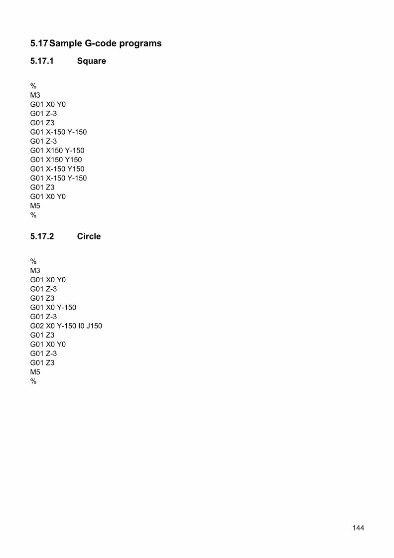
5.17Sample G-code programs
5.17.1 Square
%M3G01 X0 Y0G01 Z-3G01 Z3G01 X-150 Y-150G01 Z-3G01 X150 Y-150G01 X150 Y150G01 X-150 Y150G01 X-150 Y-150G01 Z3G01 X0 Y0M5%
5.17.2 Circle
%M3G01 X0 Y0G01 Z-3G01 Z3G01 X0 Y-150G01 Z-3G02 X0 Y-150 I0 J150G01 Z3G01 X0 Y0G01 Z-3G01 Z3M5%
144
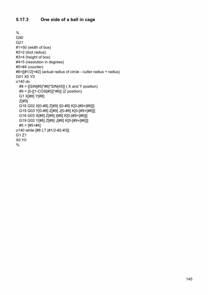
5.17.3 One side of a ball in cage
%G90G21#1=50 (width of box)#2=2 (tool radius)#3=4 (height of box)#4=5 (resolution in degrees)#5=#4 (counter)#6=[[#1/2]+#2] (actual radius of circle - cutter radius + radius) G01 X0 Y0o140 do #8 = [[SIN[#5]*#6]*SIN[45]] ( X and Y position) #9 = [0-[[1-COS[#5]]*#6]] (Z position) G1 X[#8] Y[#8] Z[#9] G18 G02 X[0-#8] Z[#9] I[0-#8] K[0-[#9+[#6]]] G19 G03 Y[0-#8] Z[#9] J[0-#8] K[0-[#9+[#6]]] G18 G03 X[#8] Z[#9] I[#8] K[0-[#9+[#6]]] G19 G02 Y[#8] Z[#9] J[#8] K[0-[#9+[#6]]] #5 = [#5+#4]o140 while [#8 LT [#1/2-#2-#3]]G1 Z1X0 Y0%
145
Table of Contents
1 Introduction........................................................................................................................................ 3
1.1 Overview.....................................................................................................................................3
1.2 Features and specifications:........................................................................................................51.2.1 Mk1 - 4 axes USB CNC controller........................................................................................61.2.2 Mk2 - 9 axes USB CNC controller........................................................................................61.2.3 Mk2/4 - 4 axes USB CNC controller.....................................................................................6
1.3 System Requirements.................................................................................................................7
2 Hardware........................................................................................................................................... 8
2.1 Installation...................................................................................................................................8
2.2 Mk1 - 4 axis CNC USB controller description..............................................................................92.2.1 Mk1 MOTOR connector.....................................................................................................102.2.2 Mk1 CONNECTOR connector............................................................................................112.2.3 Mk1 JOG connector...........................................................................................................122.2.4 Mk1 LIMIT connector.........................................................................................................132.2.5 Mk1 EXT connector ...........................................................................................................14
2.3 Mk2 - 9 axis CNC USB controller description............................................................................152.3.1 Mk2 MOTOR connector.....................................................................................................162.3.2 Mk2 MOTOR 5-9 connector...............................................................................................172.3.3 Mk2 JOG connector...........................................................................................................182.3.4 Mk2 LIMIT connector.........................................................................................................192.3.5 Mk2 CTRL connector.........................................................................................................212.3.6 Mk2 INPUT connector........................................................................................................222.3.7 Mk2 OUTPUT connector....................................................................................................232.3.8 Mk2 EXT connector............................................................................................................242.3.9 Mk2 POT connector...........................................................................................................252.3.10 Mk2 USB connector.........................................................................................................262.3.11 Mk2 Power terminal and Power options jumpers ............................................................262.3.12 Mk2 LED indicators..........................................................................................................26
2.4 Mk2/4 - 4 axis CNC USB controller description.........................................................................272.4.1 Mk2/4 MOTOR connector..................................................................................................282.4.2 Mk2/4 JOG connector........................................................................................................292.4.3 Mk2/4 OUTPUT connector.................................................................................................302.4.4 Mk2/4 LIMIT connector......................................................................................................312.4.5 Mk2/4 INPUT connector.....................................................................................................322.4.6 Mk2/4 POT connector........................................................................................................332.4.7 Mk2/4 DB25 connector.......................................................................................................342.4.8 Mk2/4 USB connector........................................................................................................35
146
2.4.9 Mk2/4 Power terminal and Power options jumpers ...........................................................352.4.10 Mk2/4 LED indicators.......................................................................................................35
2.5 Adapter with screw terminals.....................................................................................................36
2.6 Jogging keyboard......................................................................................................................37
2.7 Output board.............................................................................................................................38
2.8 MPG Pendant Adapter..............................................................................................................39
2.9 SD Card Adapter.......................................................................................................................40
3 Software.......................................................................................................................................... 41
3.1 Overview...................................................................................................................................41
3.2 Installation.................................................................................................................................423.2.1 Software installation...........................................................................................................423.2.2 Driver installation................................................................................................................453.2.3 Completing driver installation (Windows XP)......................................................................473.2.4 Completing driver installation (Windows 7)........................................................................49
3.3 Main window.............................................................................................................................503.3.1 Position panel....................................................................................................................513.3.2 State panel.........................................................................................................................523.3.3 Program panel...................................................................................................................533.3.4 Graphical program visualization display.............................................................................543.3.5 G-code panel.....................................................................................................................543.3.6 Manual data input (MDI) panel...........................................................................................543.3.7 Toolbar...............................................................................................................................553.3.8 File menu...........................................................................................................................57
3.3.8.1 Open.........................................................................................................................573.3.8.2 Close.........................................................................................................................573.3.8.3 Recent Files..............................................................................................................573.3.8.4 Import G-Code..........................................................................................................583.3.8.5 Import DXF................................................................................................................583.3.8.6 Import PLT/HPGL......................................................................................................603.3.8.7 Import NC Drill...........................................................................................................603.3.8.8 Import Gerber............................................................................................................613.3.8.9 Import Image.............................................................................................................623.3.8.10 Import Text..............................................................................................................633.3.8.11 Import Airfoil............................................................................................................643.3.8.12 G-Code Wizard.......................................................................................................653.3.8.13 Export Toolpath To G-code.....................................................................................653.3.8.14 Export Toolpath to DXF...........................................................................................653.3.8.15 Export Toolpath to CSV...........................................................................................653.3.8.16 Export Toolpath to RAW..........................................................................................653.3.8.17 Settings...................................................................................................................653.3.8.18 Import Settings........................................................................................................653.3.8.19 Export Settings........................................................................................................65
147
3.3.8.20 Language................................................................................................................653.3.8.21 Exit..........................................................................................................................65
3.3.9 View menu.........................................................................................................................663.3.9.1 Origin........................................................................................................................663.3.9.2 Top View...................................................................................................................663.3.9.3 Side View..................................................................................................................663.3.9.4 Front View.................................................................................................................663.3.9.5 Perspective View.......................................................................................................663.3.9.6 Zoom In.....................................................................................................................663.3.9.7 Zoom Out..................................................................................................................663.3.9.8 Zoom Tool.................................................................................................................663.3.9.9 Zoom Extents............................................................................................................673.3.9.10 Center Tool.............................................................................................................673.3.9.11 Center View.............................................................................................................673.3.9.12 Change View...........................................................................................................673.3.9.13 Simulate..................................................................................................................673.3.9.14 Window / Jog...........................................................................................................673.3.9.15 Window / Reset.......................................................................................................673.3.9.16 Window / Large.......................................................................................................673.3.9.17 Show.......................................................................................................................683.3.9.18 Material...................................................................................................................68
3.3.10 Program menu.................................................................................................................693.3.10.1 Lines.......................................................................................................................693.3.10.2 Bookmarks..............................................................................................................693.3.10.3 Shift.........................................................................................................................703.3.10.4 Scale.......................................................................................................................703.3.10.5 Mirror.......................................................................................................................703.3.10.6 Rotate.....................................................................................................................703.3.10.7 Set Speed...............................................................................................................703.3.10.8 Copy XYZ → UVW..................................................................................................713.3.10.9 Swap XYZ ↔ UVW.................................................................................................713.3.10.10 Convert Arcs To Lines...........................................................................................713.3.10.11 Convert All To Lines.............................................................................................713.3.10.12 Edit G-Code..........................................................................................................713.3.10.13 Edit DXF................................................................................................................713.3.10.14 Copy To Clipboard................................................................................................713.3.10.15 Paste from Clipboard.............................................................................................71
3.3.11 Machine menu.................................................................................................................723.3.11.1 Emergency Stop......................................................................................................723.3.11.2 Start........................................................................................................................723.3.11.3 Start Loop...............................................................................................................723.3.11.4 Start Raw File..........................................................................................................723.3.11.5 Stop.........................................................................................................................723.3.11.6 Pause......................................................................................................................72
148
3.3.11.7 Bookmarks..............................................................................................................733.3.11.8 Mist.........................................................................................................................733.3.11.9 Flood.......................................................................................................................733.3.11.10 Spindle..................................................................................................................733.3.11.11 Outputs.................................................................................................................733.3.11.12 Go To....................................................................................................................733.3.11.13 Set Position...........................................................................................................743.3.11.14 Offset....................................................................................................................74
3.3.11.14.1 Offset / From Tool Sensor..............................................................................753.3.11.14.2 Offset / From Program...................................................................................753.3.11.14.3 Offset / From Material....................................................................................753.3.11.14.4 Offset / Measure Offset Z...............................................................................753.3.11.14.5 Offset / Sensor Setup....................................................................................76
3.3.11.15 Tools.....................................................................................................................763.3.11.15.1 Tools / Active.................................................................................................763.3.11.15.2 Tools / Change..............................................................................................763.3.11.15.3 Tools / Select.................................................................................................763.3.11.15.4 Tools / Zero Tool Offset.................................................................................763.3.11.15.5 Tools / Measure Tool Offset...........................................................................763.3.11.15.6 Tools / Measure Tool Offset Here..................................................................763.3.11.15.7 Tools / Set Tool Offset...................................................................................763.3.11.15.8 Tools / Measure Tool Length.........................................................................773.3.11.15.9 Tools / Measure Tool Length Here.................................................................77
3.3.11.16 Home....................................................................................................................773.3.11.17 Transformation......................................................................................................77
3.3.11.17.1 Transformation / Transformation Matrix.........................................................773.3.11.17.2 Transformation / Calculate Transformation Matrix.........................................773.3.11.17.3 Transformation / Calculate Matrix From Points..............................................783.3.11.17.4 Transformation / Capture & Measure Points / Measure.................................783.3.11.17.5 Transformation / Capture & Measure Points / Capture..................................793.3.11.17.6 Transformation / Capture & Measure Points / Clear......................................793.3.11.17.7 Transformation / Capture & Measure Points / Load Points............................793.3.11.17.8 Transformation / Capture & Measure Points / Save Points............................793.3.11.17.9 Transformation / Capture & Measure Points / Show Camera........................803.3.11.17.10 Transformation / Capture & Measure Points / Sensor..................................80
3.3.11.18 Soft Limits.............................................................................................................813.3.11.19 Firmware...............................................................................................................81
3.3.12 Help menu........................................................................................................................823.3.12.1 Help.........................................................................................................................823.3.12.2 Activate License......................................................................................................823.3.12.3 Import License.........................................................................................................823.3.12.4 Export License........................................................................................................823.3.12.5 Log..........................................................................................................................823.3.12.6 Check For Updates.................................................................................................82
149
3.3.12.7 About.......................................................................................................................82
3.4 Settings.....................................................................................................................................833.4.1 General..............................................................................................................................84
3.4.1.1 Units..........................................................................................................................843.4.1.2 Speed........................................................................................................................843.4.1.3 Display......................................................................................................................843.4.1.4 Default button............................................................................................................853.4.1.5 Colors... button..........................................................................................................853.4.1.6 Keys... button............................................................................................................863.4.1.7 IO... button................................................................................................................863.4.1.8 Calibration... button...................................................................................................87
3.4.2 Axes 1................................................................................................................................883.4.2.1 Axes..........................................................................................................................88
3.4.3 Axes 2................................................................................................................................893.4.3.1 Axes..........................................................................................................................893.4.3.2 Acceleration..............................................................................................................893.4.3.3 Backlash...................................................................................................................893.4.3.4 Park Positions...........................................................................................................89
3.4.4 Axes 3................................................................................................................................903.4.4.1 Limits.........................................................................................................................903.4.4.2 Homing......................................................................................................................90
3.4.5 Misc...................................................................................................................................923.4.5.1 ExtPin........................................................................................................................93
3.4.6 Outputs..............................................................................................................................943.4.6.1 Spindle (M3, M4, M5)................................................................................................943.4.6.2 Coolant (M7, M8, M9)................................................................................................943.4.6.3 Pause........................................................................................................................953.4.6.4 Motor Enable.............................................................................................................953.4.6.5 M62, M63, M64, M65................................................................................................953.4.6.6 Invert Output.............................................................................................................95
3.4.7 Limits.................................................................................................................................963.4.8 Jog.....................................................................................................................................973.4.9 Input...................................................................................................................................983.4.10 Control.............................................................................................................................993.4.11 Tools..............................................................................................................................1003.4.12 Tool Change..................................................................................................................101
3.4.12.1 Tool Change..........................................................................................................1013.4.12.2 From Tool Table....................................................................................................102
3.4.13 Tool Sensor....................................................................................................................1043.4.13.1 Tool Sensor Fixed.................................................................................................1043.4.13.2 Tool Sensor Movable............................................................................................105
3.4.14 Materials........................................................................................................................1063.4.15 Parameters....................................................................................................................1073.4.16 I2C.................................................................................................................................1083.4.17 Notes..............................................................................................................................109
150
3.4.18 Scripts............................................................................................................................110
4 How to .......................................................................................................................................... 111
4.1.1 How to activate, import, request and export license?.......................................................1114.1.2 How to connect motor driver with optoisolated inputs?.....................................................1134.1.3 How to connect and setup Output board?........................................................................1144.1.4 How to configure settings for MPG pendant?...................................................................116
5 G-Code.......................................................................................................................................... 117
5.1 Overview.................................................................................................................................117
5.2 Format of a Line......................................................................................................................117
5.3 Line Number ...........................................................................................................................118
5.4 Word ...................................................................................................................................... 118
5.5 Number...................................................................................................................................118
5.6 Parameters .............................................................................................................................119
5.7 Expressions and Binary Operations........................................................................................119
5.8 Unary Operation Value............................................................................................................120
5.9 Comments and Messages.......................................................................................................120
5.10 Item Repeats.........................................................................................................................121
5.11 Item Order.............................................................................................................................121
5.12 Modal and Non-modal modes...............................................................................................122
5.13 Modal Groups........................................................................................................................122
5.14 G - Codes..............................................................................................................................1235.14.1 G00 - Rapid Motion (Linear Motion at Traverse Rate)................................................1235.14.2 G01 - Linear Feed (Linear Motion at Feed Rate).........................................................1235.14.3 G02 - Arc/Helix Feed (CW)..........................................................................................1245.14.4 G03 - Arc/Helix Feed (CCW) (Arc at Feed Rate).........................................................1245.14.5 G04 - Dwell..................................................................................................................1265.14.6 G7 - Lathe Diameter Mode...........................................................................................1265.14.7 G8 - Lathe Radius Mode..............................................................................................1265.14.8 G10 L1 - Set Tool Table...............................................................................................1265.14.9 G10 L2 - Coordinate System Origin Setting.................................................................1265.14.10 G10 L9 - Set Machine Position Without Move..............................................................1275.14.11 G17 - XY-Plane Selection............................................................................................1275.14.12 G18 - XZ-Plane Selection.............................................................................................1275.14.13 G19 - YZ-Plane Selection.............................................................................................1275.14.14 G20 - Inch System Selection........................................................................................1275.14.15 G21 - Millimeter System Selection...............................................................................1275.14.16 G28 - Return to Predefined Position.............................................................................1275.14.17 G30 - Return to Predefined Position.............................................................................1275.14.18 G33 - Spindle Synchronized Motion.............................................................................1285.14.19 G40 - Cancel Cutter Radius Compensation.................................................................1285.14.20 G41 - Start Cutter Radius Compensation Left..............................................................128
151
5.14.21 G42 - Start Cutter Radius Compensation Right............................................................1285.14.22 G43 - Tool Length Offset..............................................................................................1285.14.23 G49 - Cancel Tool Length Offset..................................................................................1295.14.24 G53 - Motion in Machine Absolute Coordinates...........................................................1295.14.25 G54 - Use Preset Work Coordinate System 1..............................................................1295.14.26 G55 - Use Preset Work Coordinate System 2..............................................................1295.14.27 G56 - Use Preset Work Coordinate System 3..............................................................1295.14.28 G57 - Use Preset Work Coordinate System 4..............................................................1295.14.29 G58 - Use Preset Work Coordinate System 5..............................................................1295.14.30 G59 - Use Preset Work Coordinate System 6..............................................................1295.14.31 G59.1 - Use Preset Work Coordinate System 7...........................................................1295.14.32 G59.2 - Use Preset Work Coordinate System 8...........................................................1295.14.33 G59.3 - Use Preset Work Coordinate System 9...........................................................1295.14.34 G61 - Set Path Control Mode: Exact Path....................................................................1305.14.35 G61.1 - Set Path Control Mode: Exact Stop.................................................................1305.14.36 G64 - Set Path Control Mode: Continuous...................................................................1305.14.37 G73 - Drilling Cycle with Chip Breaking........................................................................1305.14.38 G76 - Threading Cycle.................................................................................................1305.14.39 G80 - Cancel Motion Mode (Including any Canned Cycle)...........................................1325.14.40 Canned Cycles (G80 - G89).........................................................................................1325.14.41 G81 - Canned Cycle: Drilling........................................................................................1345.14.42 G82 - Canned Cycle: Drilling with Dwell.......................................................................1355.14.43 G83 - Canned Cycle: Peck Drilling...............................................................................1355.14.44 G84 - Canned Cycle: Right Hand Tapping...................................................................1365.14.45 G85 - Canned Cycle: Boring, No Dwell, Feed Out........................................................1365.14.46 G86 - Canned Cycle: Boring, Spindle Stop, Rapid Out................................................1365.14.47 G87 - Canned Cycle: Back Boring................................................................................1375.14.48 G88 - Canned Cycle: Boring, Spindle Stop, Manual Out..............................................1375.14.49 G89 - Canned Cycle: Boring, Dwell, Feed Out.............................................................1385.14.50 G90 - Absolute Distance Mode....................................................................................1385.14.51 G91 - Incremental Distance Mode................................................................................1385.14.52 G92 - Offset Coordinate Systems and Set Parameters................................................1385.14.53 G92.1 - Cancel Offset Coordinate Systems and Set Parameters to Zero ....................1395.14.54 G92.2 - Cancel Offset Coordinate Systems But Do Not Reset Parameters..................1395.14.55 G92.3 - Apply Parameters to Offset Coordinate Systems............................................1395.14.56 G93 - Inverse Time Feed Rate Mode...........................................................................1395.14.57 G94 - Units Per Minute Feed Rate Mode.....................................................................1395.14.58 G95 - Units Per Revolution Feed Rate Mode...............................................................1405.14.59 G98 - Initial level Return in Canned Cycles..................................................................1405.14.60 G99 - R-point Level Return in Canned Cycles..............................................................140
5.15 M - Codes..............................................................................................................................1405.15.1 M0 - Program Stop.......................................................................................................1405.15.2 M1 - Optional Program Stop.........................................................................................1405.15.3 M2 - Program End........................................................................................................1405.15.4 M30 - Program End, Pallet Shuttle, and Reset.............................................................1415.15.5 M60 - Pallet Shuttle and Program Stop........................................................................1415.15.6 M3 - Turn Spindle Clockwise........................................................................................141
152
5.15.7 M4 - Turn Spindle Counterclockwise............................................................................1415.15.8 M5 - Stop Spindle Turning............................................................................................1415.15.9 M6 - Tool Change........................................................................................................1415.15.10 M7 - Mist Coolant On...................................................................................................1415.15.11 M8 - Flood Coolant On.................................................................................................1415.15.12 M9 - Mist and Flood Coolant Off...................................................................................1415.15.13 M48 - Enable Speed and Feed Overrides....................................................................1415.15.14 M49 - Disable Speed and Feed Overrides...................................................................1415.15.15 M62 - Output................................................................................................................1425.15.16 M63 - Output................................................................................................................1425.15.17 M64 - Output................................................................................................................1425.15.18 M65 - Output................................................................................................................142
5.16 Other Codes..........................................................................................................................1435.16.1 F - Set Feed Rate...........................................................................................................1435.16.2 S - Set Spindle Speed....................................................................................................1435.16.3 T - Select Tool................................................................................................................143
5.17 Sample G-code programs.....................................................................................................1445.17.1 Square...........................................................................................................................1445.17.2 Circle..............................................................................................................................1445.17.3 One side of a ball in cage...............................................................................................145
153