CNC 8070 - Installation manual · or translated into another language without Fagor Automation’s...
458
CNC 8070 REF. 0504 (SOFT V02.0X) INSTALLATION MANUAL (Soft V02.0x) Ref. 0504
Transcript of CNC 8070 - Installation manual · or translated into another language without Fagor Automation’s...

CN
C 8
070
REF. 0504
(SOFT V02.0X)
INSTALLATION MANUAL(Soft V02.0x) Ref. 0504


Unauthorized copying or distributing of this software is prohibited.
All rights reserved. No part of this documentation may be transmitted, transcribed, stored in a backup device or translated into another language without Fagor Automation’s consent.
Microsoft® and Windows® are registered trademarks of Microsoft Corporation, U.S.A.
Installation manual


PRELIMINARY WARNINGS
MACHINE SAFETY
It is up to the machine manufacturer to make sure that the safety of the machine is enabledin order to prevent personal injury and damage to the CNC or to the products connected to it.
On start-up and while validating CNC parameters, it checks the status of the following safetyelements:
• Feedback alarm for analog axes.
• Software limits for analog and sercos linear axes.
• Following error monitoring for analog and sercos axes (except the spindle) both at theCNC and at the drives.
• Tendency test on analog axes.
If any of them is disabled, the CNC shows a warning message and it must be enabled toguarantee a safe working environment.
FAGOR AUTOMATION shall not be held responsible for any personal injuries or physicaldamage caused or suffered by the CNC resulting from any of the safety elements beingdisabled.
HARDWARE EXPANSIONS
FAGOR AUTOMATION shall not be held responsible for any personal injuries or physicaldamage caused or suffered by the CNC resulting from any hardware manipulation bypersonnel unauthorized by Fagor Automation.
If the CNC hardware is modified by personnel unauthorized by Fagor Automation, it will nolonger be under warranty.
COMPUTER VIRUSES
FAGOR AUTOMATION guarantees that the software installed contains no computer viruses.It is up to the user to keep the unit virus free in order to guarantee its proper operation.
Computer viruses at the CNC may cause it to malfunction. An antivirus software is highlyrecommended if the CNC is connected directly to another PC, it is part of a computer networkor floppy disks or other computer media is used to transmit data.
FAGOR AUTOMATION shall not be held responsible for any personal injuries or physicaldamage caused or suffered by the CNC due a computer virus in the system.
If a computer virus is found in the system, the unit will no longer be under warranty.
Installation manual


Installation manual
CNC 8070
(SOFT V02.0X)
i
INDEX
1. Software installation
1.1 Software installation ...........................................................................................................11.2 Updating the software version............................................................................................31.3 Software configuration .......................................................................................................41.3.1 MTB (Machine Tool Builder) directory ............................................................................51.3.2 USERS directory ............................................................................................................6
2. Machine parameters
2.1 Parameter matching between the CNC and the Sercos drive............................................92.2 General machine parameters...........................................................................................132.2.1 General machine parameters. Channels ......................................................................272.3 Machine parameters for the axes.....................................................................................402.3.1 Machine parameters for the axes. Work sets................................................................592.4 Machine parameters for JOG mode.................................................................................782.4.1 Example of how to set the handwheels and JOG keys.................................................812.5 Machine parameters for the M function table ...................................................................842.6 Machine parameters for kinetics ......................................................................................862.7 Machine parameters for the magazine...........................................................................1012.7.1 Types of tool magazine ...............................................................................................1042.8 Machine parameters for HMI (Interface) ........................................................................1062.9 OEM machine parameters .............................................................................................1102.10 Alphabetical listing of machine parameters....................................................................112
3. Concepts
3.1 Tandem axis ...................................................................................................................1173.1.1 Tandem axis configuration. Machine parameters .......................................................1193.1.2 Effect of the preload....................................................................................................1223.1.3 Tandem axis configuration. Block diagram .................................................................1243.1.4 Tandem related variables............................................................................................1273.1.5 Tandem adjustment procedure ...................................................................................128
4. Introduction to the PLC
4.1 PLC program..................................................................................................................1324.2 Modular structure of the PLC program...........................................................................1334.2.1 PLC module execution................................................................................................1344.3 PLC program execution..................................................................................................1354.4 PLC resources ...............................................................................................................1364.4.1 Numbering of the physical inputs and outputs............................................................1394.5 Operation of a timer .......................................................................................................1414.5.1 Monostable mode. TG1 input .....................................................................................1444.5.2 Delayed activation mode. TG2 input ...........................................................................1464.5.3 Delayed deactivation mode. TG3 input.......................................................................1484.5.4 Signal limiting mode. TG4 Input..................................................................................1504.6 Operation of a counter ...................................................................................................152
5. PLC programming
5.1 Directing instructions......................................................................................................1575.2 Consulting instructions...................................................................................................1625.3 Operators and symbols ..................................................................................................165

Installation manual
CNC 8070
(SOFT V02.0X)
ii
5.4 Action instructions. .........................................................................................................1675.4.1 Assignment binary instructions...................................................................................1685.4.2 Conditional binary instructions....................................................................................1695.4.3 Sequence breaking action instructions .......................................................................1705.4.4 Arithmetic action instructions......................................................................................1715.4.5 Logic action instructions .............................................................................................1745.4.6 Specific action instructions .........................................................................................1765.4.7 Action instruction of the electronic cam ......................................................................1795.4.8 Action instructions for independent axes ....................................................................1815.5 Summary programming commands...............................................................................183
6. CNC-PLC communication
6.1 Auxiliary -M- functions....................................................................................................1906.1.1 Special considerations with the multi-spindle option and channels ............................1926.2 Auxiliary H functions.......................................................................................................1946.2.1 Special considerations with the multi-spindle option and channels ............................1956.3 Auxiliary S function.........................................................................................................1966.3.1 Special considerations with the multi-spindle option and channels ............................1976.4 Transferring auxiliary functions -M-, -H-, -S- ..................................................................1986.4.1 Synchronized transfer .................................................................................................2006.4.2 Non-synchronized transfer..........................................................................................2016.5 Displaying PLC errors and messages............................................................................202
7. Logic CNC inputs and outputs
7.1 General consulting signals .............................................................................................2067.2 Consulting signals for axes and spindles .......................................................................2157.3 Consulting signals for the spindle ..................................................................................2217.4 Consultation signals of the independent interpolator .....................................................2227.5 Tool manager consulting signals ....................................................................................2237.6 Keystroke consulting signals ..........................................................................................2257.7 General modifiable signals.............................................................................................2287.8 Modifiable signals for axes and spindles........................................................................2337.9 Spindle modifiable signals..............................................................................................2377.10 Modifiable signals of the independent interpolator.........................................................2407.11 Tool manager modifiable signals....................................................................................2417.12 Keystroke modifiable signals ..........................................................................................2457.13 Alphabetical listing of marks (M) and registers (R) ........................................................248
8. Tool and magazine management
8.1 Types of tool magazine ..................................................................................................2528.2 Tool table, active tool table and tool magazine table......................................................2538.3 Communication between manager and PLC .................................................................2548.3.1 Manager --> PLC communication ...............................................................................2558.3.2 PLC --> Manager communication ...............................................................................2578.3.3 Manager Emergency ..................................................................................................2598.3.4 Tool monitoring ...........................................................................................................2608.4 Variables related to tool magazine management ...........................................................2618.5 Tool loading and unloading from the magazines............................................................2628.6 Turret type ......................................................................................................................2648.6.1 Values of the TMOPERATION and marks to be activated by the PLC .......................2658.6.2 Communication between the PLC and the M06 subroutine .......................................2668.6.3 Program of the M06 subroutine ..................................................................................2678.6.4 Basic PLC programming.............................................................................................2688.7 Synchronous magazine without changer arm................................................................2698.7.1 Values of the TMOPERATION and marks to be activated by the PLC .......................2708.7.2 Communication between the PLC and the M06 subroutine .......................................2738.7.3 Program of the M06 subroutine ..................................................................................2748.7.4 Basic PLC programming.............................................................................................2788.8 Synchronous magazine. Changer arm with independent movements. ..........................2808.8.1 Values of the TMOPERATION and marks to be activated by the PLC .......................2818.8.2 Communication between the PLC and the M06 subroutine .......................................2858.8.3 Program of the M06 subroutine ..................................................................................2868.8.4 Basic PLC programming.............................................................................................291
Installation manual
CNC 8070
(SOFT V02.0X)
iii
8.9 Synchronous magazine. Tool changer arm with 2 holders.............................................2938.9.1 Values of the TMOPERATION and marks to be activated by the PLC .......................2948.9.2 Communication between the PLC and the M06 subroutine .......................................2988.9.3 Program of the M06 subroutine ..................................................................................2998.9.4 Basic PLC programming.............................................................................................3048.10 Asynchronous magazine................................................................................................3068.10.1 Values of the TMOPERATION and marks to be activated by the PLC .......................3078.10.2 Communication between the PLC and the M06 subroutine .......................................3128.10.3 Program of the M06 subroutine ..................................................................................3148.10.4 Basic PLC programming.............................................................................................320
9. CNC variables
9.1 Understanding the description of the variables ..............................................................3239.1.1 Access to numeric values from the PLC.....................................................................3269.1.2 Accessing the variables in a single-channel system...................................................3279.1.3 Accessing the variables of a single-channel system ..................................................3299.2 Related to general machine parameters ........................................................................3329.2.1 Channel related ..........................................................................................................3349.3 Related to axis machine parameters..............................................................................3369.3.1 Related to gear parameters ........................................................................................3399.4 Related to jog mode parameters....................................................................................3429.5 Related to "M" function parameters ...............................................................................3439.6 Related to kinematic parameters ...................................................................................3449.7 Related to magazine parameters ...................................................................................3459.8 Related to OEM parameters ..........................................................................................3469.9 User tables related .........................................................................................................3479.10 Tool related.....................................................................................................................3499.10.1 Variables only used during block preparation .............................................................3519.11 PLC related ....................................................................................................................3529.12 Jog mode related ...........................................................................................................3539.13 Coordinate related..........................................................................................................3559.14 Feedrate related.............................................................................................................3579.15 Related to the spindle speed..........................................................................................3589.16 Related to the programmed functions ............................................................................3599.17 Related to the independent axes ...................................................................................3649.18 Related to the machine configuration.............................................................................3659.19 Other variables...............................................................................................................3689.20 Alphabetical listing of variables ......................................................................................371
Appendix
A CNC general characteristics ..........................................................................................383B CNC maintenance..........................................................................................................385C Summary of CNC machine parameters .........................................................................387D Summary of PLC programming commands...................................................................395E Logic CNC inputs and outputs .......................................................................................401F Summary of CNC variables............................................................................................405G Key codes (QWERTY keyboard)....................................................................................421


CNC 8070
(SOFT V02.0X)
I
ABOUT THIS MANUAL
Title
Installation Manual.
Type of documentation
It describes how to install and start up the CNC.
Internal code
It is part of the manual directed to the OEM. The code of the manualdepends on the software version –standard– or –advanced–.
Version
It corresponds to the software version: (Soft V02.0x).
Start-up
Warning
CNC 8070 OEM (IN) STAN Code 03753601CNC 8070 OEM (IN) AVANZ Code 03753621
Verify that the machine that integrates this CNC meets the89/392/CEE Directive.
Before starting up the CNC, read the instructions of chapter 1 in theInstallation Manual.
The information described in this manual may be changed due totechnical modifications.
FAGOR AUTOMATION, S. Coop. reserves the right to make anychanges to the contents of this manual without prior notice.


CNC 8070
(SOFT V02.0X)
III
ABOUT THE PRODUCT
Software options
Bear in mind that some of the features described in this manualdepend on the software options that are installed.
“M” model “GP” model
Number of execution channels 1 to 4 1 to 4
Number of axes 4 to 28 4 to 28
Number of spindles 1 to 4 1 to 4
Number of tool magazines 1 to 4 1 to 4
COCOM version Option Option
Sercos digital drive system Option Option
Tool radius compensation Standard Option
"C" axis Standard Not available
RTCP transformation Option Not available
High speed machining (HSC). Option Option
Probing canned cycles Option Not available
Tandem axes Option Not available
Synchronism and cams Option Not available


CNC 8070
(SOFT V02.0X)
V
VERSION HISTORY
Here is a list of the features added in each software version and the manuals that describe them.
The version history uses the following abreviations:
Software V01.0x February of 2002
First version.
Software 1.1x September of 2002
INST Installation manualPRG Programming manualOPT Operation manual
FeatureProbe management through a digital input. It is not possible to manage it through the“Counter” module connector.
INST
Set the numbering of the digital I/O. INSTKinetics for rotary table. INSTPossibility to park and unpark SERCOS axes from the PLC. INSTKeyboard simulation from the PLC. INSTNew treatment of the JOG panel (Key + Direction). INST / OPTNew machine parameters.
• Probe setting.
• Numbering of the digital I/Os.
• Kinetics for rotary table.
• Repositioning feedrate after a tool inspection.
INST
New variables.
• Probe setting.
• Numbering of the digital I/Os.
• Key simulation.
• Repositioning feedrate after a tool inspection.
• General scaling factor.
• Kinetics dimensions.
INST
PRG
General scaling factor (#SCALE). PRGPobring canned cycles (#PROBE). PRGProbe selection (#SELECT PROBE). PRGProgramming of warnings (#WARNING). PRGBlock repetition ($RPT). PRGImproved programming of high speed machining (#HSC). PRGImproved programming of axis swapping (#SET AX, #CALL AX, #FREE AX, #RENAME). PRGMacros: The number of macros in a program is now limited to 50. PRGImproved tool table. OPTProtection passwords. OPTManual mode (jog). Tool calibration with or without probe. OPTManual mode (jog). Automatic loading of zero offsets table. OPT

VIII
CNC 8070
Ver
sion
his
tory
(SOFT V02.0X)
VI
January of 2005 Software: 2.0x
Manual mode (jog). Programming of feedrate “F” and spindle speed “S”. OPTAxis selection/deselection for handwheel jog. OPTTheoretical path simulation. OPTDefinition of the first block of a block search. OPTConfirm that the CNC is not in automatic mode when executing a program. OPTSyntax check in MDI. OPT
Feature
FeatureOperation under Windows XP INSTEmergency shutdown with battery (Central unit PC104) OPTNew languages (Basque and Portuguese) INSTMulti-channel system, up to 4 channels.
• Spindle swapping
• Axis swapping
• Communication and synchronization between channels.
• Common arithmetic parameters.
• Access to variables per channel.
INST
PRG
OPT
Multi-spindle system, up to 4 spindles PRG / INSTTool management with up to 4 magazines. INSTTandem axis. INSTNew kinematics table-spindle (TYPE13 to TYPE16). INSTNew kinematics for C axis (TYPE 41 to TYPE 43) INSTParameter matching between the CNC and the Sercos drive INSTNew machine parameters.
• Warning level on Gantry axes (WARNCOUPE)
• Placing the vertical softkeys on the right or on the left (VMENU).
• Apply cross compensation to either theoretical or real coordinates (TYPCROSS).
• Apply leadscrew compensation to either theoretical or real coordinates (TYPLSCRW).
• Defining the default compensation mode (IRCOMP).
• Defining the type of reference pulse (REFPULSE).
• Memory sharing between applications (PLCDATASIZE).
• Generic OEM machine parameters (MTBPAR).
• Reading Sercos variables from the CNC (DRIVEVAR).
• Backlash peak compensation (BAKANOUT, BAKTIME, ACTBAKAN).
INST
The behavior of rotary axes has been changed. Machine parameters AXISMODE,UNIDIR, SHORTESTWAY.
INST
Possibility of Sercos transmission at 8 Mhz and 16 Mhz. Parameter SERBRATE. INSTDefine the anticipation time for the axes to be considered to be in position. Machineparameter ANTIME and the PLC mark ADVINPOS.
INST
The "(V.).TM.MZWAIT " variable is not necessary in the subroutine associated with M06. INSTFilters to eliminate the resonance of the spindle when it works as C axis or in rigid tapping. INSTPLC. The TMOPERATION may take the values 13 and 14. INSTPLC. New mark MMCWDG to detect that the lockup of the operating system. INSTPLC. Accessing arithmetic parameters and OEM parameters with CNCRD returns thevalue multiplied by 10000 (reading in float mode).
INST
PLC. The CNCEX command and the FREE mark to execute a CNC block. New commands at the PLC.
• New mark to disable the cross compensation tables (DISCROSS).
• New mark to correct the parallelism on Gantry axes (DIFFCOMP).
• Definition of external symbols (PDEF).
INST
New variables.
• Software version.
• Variables to be set via PLC.
• Variables for adjusting the position.
• Fine adjustment variables.
• Feedback inputs.
INST / PRG

CNC 8070
Ver
sion
his
tory
(SOFT V02.0X)
VII
Electronic-cam editor. INSTOptimize the reading and writing of variables from the PLC. Only the following will beasynchronous.
• The tool variables will be read asynchronously when the tool is neither the active onenor in the magazine.
• The tool variables will be written asynchronously whether the tool is the active one ornot.
• The variables referred to local arithmetic parameters of the active levels will be readand written asynchronously.
INST / PRG
Spindle parking and unparking. INSTThe RESETIN mark is not necessary to park/unpark axes or spindles from the PLC. INSTSercos control in velocity. INSTBehavior of the beginning and end of tool radius compensation when not programminga movement.
PRG
Changing the type of radius compensation while machining. PRGVia program, loading a tool in a specific magazine position. PRGProgramming of modal subroutines (#MCALL). PRGExecuting a block in a channel (#EXBLK). PRGProgramming the number of repetitions in the block (NR). PRGDirect resolution of 2D and 3D pockets without requiring a softkey. PRGSimulating a canned cycle of the editor separately. PRGNew method to jog the axes using the JOG keyboard. Axis keys and independentdirections.
INST / OPT
Importing DXF files from the program editor or from the profile editor. OPTImporting programs of the 8055/8055i CNC from the program editor. OPTUse a softkey to select the repositioning of the spindle after tool inspection. OPTBackup-restore utility. OPTImproved profile editor. OPTAssistance in the program editor. Contextual programming assistance.
• When programming "#", it shows the list of instructions.
• When programming "$", it shows the list of instructions.
• When programming "V.", it shows the list of variables.
OPT
Specific password for the machine parameters for kinematics. OPTSave the CAN configuration for testing it when starting up the system. OPTThe diagnosis mode shows detailed information on the Sercos connection (Type andversion of the drive and motor connected to it).
OPT
It is possible to print all the information on the configuration from any section of thediagnosis mode.
OPT
It is possible to simulate a cycle separately from the cycle editor. OPTSetup assistance.
• Oscilloscope.
• Bode diagram.
• Circularity (roundness) test.
OPT
Feature

VIII
CNC 8070
Ver
sion
his
tory
(SOFT V02.0X)
VIII
April 2005 Software: 2.03
FeatureNew values of machine parameter SERPOWSE for the "Sercos II" board. INSTIndependent-axis programming commands. INSTElectronic-cams programming commands. INSTNew signals that may be consulted and changed for the independent interpolator(electronic cam and independent axis)
INST
The simulated axes are ignored regarding the validation code.When unifying parameters, G00FEED and MAXVOLT are not sent out to the drive. INSTElectronic-cam programming instructions (#CAM ON / #CAM OFF). PRGIndependent-axis programming instructions (#MOVE ABS / #MOVE ADD / #MOVE INF/ #FOLLOW ON / #FOLLOW OFF).
PRG
G112. Change the drive’s parameter set . PRGDDSSETUP mode OPTG31. Temporary polar origin shift to the center of interpolation. PRG
CNC 8070
(SOFT V02.0X)
IX
DECLARATION OF CONFORMITY
Manufacturer:
Fagor Automation, S. Coop.
Barrio de San Andrés 19, C.P. 20500, Mondragón -Guipúzcoa-(SPAIN).
We declare:
under our responsibility that the product:
Fagor CNC8070 Numerical Control
meets the following directives:
Safety:
Electromagnetic compatibility:
As instructed by the European Community Directives 73/23/EEC,modification 93/68/ECC on Low Voltage and 89/336/CEE onElectromagnetic Compatibility.
In Mondragón on February 1st 2002.
EN 60204-1 Machine safety. Electrical equipment of the machines.
EN 50081-2 Emission.EN 55011 Radiated. Class A, Group 1.EN 55011 Conducted. Class A, Group 1.EN 61000-3-2 Current armonics.EN 61000-3-3 Flickers and Voltage fluctuations.
EN 50082-2 Immunity.EN 61000-4-2 Electrostatic discharges.EN 61000-4-4 Bursts and Fast transients.EN 61000-4-5 High Voltage conducted pulses (Surges).EN 61000-4-11 Voltage fluctuations and Outages.EN 61000-4-3 Radiofrequency radiated electromagnetic fields.EN 61000-4-6 Conducted disturbance induced by radio frequency fields.


CNC 8070
(SOFT V02.0X)
XI
SAFETY CONDITIONS
Read the following safety measures in order to prevent harming people or damage to this productand those products connected to it.
This unit may only be repaired by authorized personnel at Fagor Automation.
Fagor Automation shall not be held responsible of any physical damage or defective unitresulting from not complying with these basic safety regulations.
PRECAUTIONS AGAINST PERSONAL DAMAGE
Interconnection of modules.
Use the connection cables provided with the unit.
Use proper cables.
To prevent risks, use the proper cables for mains, Sercos and Bus Canrecomended for this unit.
Avoid electrical overloads.
In order to avoid electrical discharges and fire hazards, do not apply electricalvoltage outside the range selected on the rear panel of the Central Unit.
Ground connection.
In order to avoid electrical discharges, connect the ground terminals of all themodules to the main ground terminal. Before connecting the inputs and outputsof this unit, make sure that all the grounding connections are properly made.
Make sure that it is connected to ground.
In order to avoid electrical shock, before turning the unit on verify that the groundconnection is properly made.
Do not work in humid environments.
In order to avoid electrical discharges, always work under 90% of relativehumidity (non-condensing) and 45ºC (113ºF).
Do not work in explosive environments.
In order to avoid risks or damages, do no work in explosive environments.
PRECAUTIONS AGAINST PRODUCT DAMAGE
Working environment.
This unit is ready to be used in Industrial Environments complying with thedirectives and regulations effective in the European Community.
Fagor Automation shall not be held responsible for any damage suffered orcaused when installed in other environments (residential or homes).
Install the unit in the right place.

XIII
CNC 8070
Saf
ety
cond
ition
s
(SOFT V02.0X)
XII
It is recommended, whenever possible, to install the CNC away from coolants,chemical product, blows, etc. that could damage it.
This unit complies with the European directives on electromagneticcompatibility. Nevertheless, it is recommended to keep it away from sources ofelectromagnetic disturbance such as:
• Powerful loads connected to the same AC power line as this equipment.
• Nearby portable transmitters (Radio-telephones, Ham radio transmitters).
• Nearby radio/TV transmitters.
• Nearby arc welding machines.
• Nearby High Voltage power lines.
• Etc.
Enclosures.
The manufacturer is responsible of assuring that the enclosure involving theequipment meets all the currently effective directives of the EuropeanCommunity.
Avoid disturbances coming from the machine tool.
The machine-tool must have all the interference generating elements (relaycoils, contactors, motors, etc.) uncoupled.
Use the proper power supply.
Use an external regulated 24Vdc power supply for the keyboard and the remotemodules.
Grounding of the power supply.
The zero volt point of the external power supply must be connected to the mainground point of the machine.
Analog inputs and outputs connection.
It is recommended to connect them using shielded cables and connecting theirshields (mesh) to the corresponding pin (see chapter 1 in the InstallationManual).
Ambient conditions.
The working temperature must be between +5ºC and +45ºC (41ºF and 113ºF)
The storage temperature must be between -25ºC y 70ºC (-13ºF y 158ºF)
Monitor enclosure.
Make sure that the gaps between the Central Unit and each wall of the enclosureare respected as indicated in chapter 1 of the Installation Manual.
Use a DC fan to improve enclosure ventilation.
Main AC power switch.
This switch must be easy to access and at a distance between 0.7 and 1.7 m(2.3 and 5.6 ft) off the floor.
PROTECTIONS OF THE UNIT ITSELF
Remote modules.
All the digital inputs and outputs have galvanic isolation via optocouplersbetween the CNC circuitry and the outside.

CNC 8070
Saf
ety
cond
ition
s
(SOFT V02.0X)
XIII
PRECAUTIONS DURING REPAIR
Do not get into the inside of the unit.
Only personnel authorized by Fagor Automation may manipulate the inside ofthis unit.
Do not handle the connectors with the unit connected to AC power.
Before manipulating the connectors (inputs/outputs, feedback, etc.) make surethat the unit is not connected to AC power.
SAFETY SYMBOLS
Symbols that may appear on the manual.
Symbols that the product may carry.
Symbol of danger or prohibition.
It indicates actions or operations that may hurt people or damageproducts.
Warning symbol.
It indicates situations that certain operations could cause and thesuggested actions to prevent them.
Obligation symbol.
It indicates actions and operations that must be carried out.
Information symbol.
It indicates notes, warnings and advises.i
Ground protection symbol.
It indicates that that point must be under voltage.


CNC 8070
(SOFT V02.0X)
XV
WARRANTY TERMS
All products manufactured or marketed by Fagor Automation has a warranty period of 12 monthsfrom the day they are shipped out of our warehouses.
The mentioned warranty covers repair material and labor costs, at Fagor Automation facilities,incurred in the repair of the products.
Within the warranty period, Fagor Automation will repair or replace the products verified as beingdefective.
Fagor Automation is committed to repairing or replacing their products from the time they launchthem up to 8 years after they disappear from the product catalog.
It is entirely up to Fagor Automation to determine whether a repair is to be considered underwarranty.
Excluding clauses
The repair will take place at our facilities; therefore, all shipping expenses as well as travellingexpenses incurred by technical personnel are NOT under warranty even when the unit is underwarranty.
This warranty will be applied so long as the equipment has been installed according to theinstructions, it has not been mistreated or damaged by accident or negligence and has beenmanipulated by personnel authorized by Fagor Automation.
If once the service call or repair has been completed, the cause of the failure is not to be blamedON the FAGOR product, the customer must cover all generated expenses according to currentfees.
No other implicit or explicit warranty is covered and FAGOR AUTOMATION shall not be heldresponsible, under any circumstances, of the damage which could be originated.
Service contracts
Service and Maintenance Contracts are available for the customer within the warranty periodas well as outside of it.


CNC 8070
(SOFT V02.0X)
XVII
MATERIAL RETURNING TERMS
When sending the Central Unit or the Remote Modules, pack them in its original package andpackaging material. If the original packaging material is not available, pack it as follows:
1. Get a cardboard box whose three inside dimensions are at least 15cm (6 inches) larger thanthose of the unit. The cardboard being used to make the box must have a resistance of 170Kg(375 lb.).
2. Attach a label indicating the owner of the unit, person to contact, type of unit and serialnumber. In case of malfunction also indicate symptom and a brief description of the problem.
3. Wrap the unit in a polyethylene roll or similar material to protect it.
When sending the Central Unit, protect especially the screen.
4. Pad the unit inside the cardboard box with poly-utherane foam on all sides.
5. Seal the cardboard box with packing tape or industrial staples.


CNC 8070
(SOFT V02.0X)
XIX
ADDITIONAL REMARKS
Mount the CNC away from coolants, chemical products, blows, etc. which could damage it.
Before turning the unit on, verify that the ground connections have been properly made.
In order to avoid electrical shock at the Central Unit, use the proper power (mains) cable. Use3-wire power cables (one for ground connection).
In case of a malfunction or failure, disconnect it and call the technical service. Do not get intothe inside of the unit.


CNC 8070
(SOFT V02.0X)
XXI
RELATED DOCUMENTATION
Manuals directed to the machine manufacturer or to the person incharge of doing the installation and start-up of the CNC.
Hardware manual.
It describes the hardware configuration and the technical data ofeach element.
Installation Manual.
It describes how to install and start up the CNC.
Manuals directed to the end user; that is, to the CNC operator.
Operating Manual.
Describes how to operate the CNC.
Programming Manual.
It describes how to program the CNC.
Examples manual.
It contains programming examples.
Other manuals, directed to the machine manufacturer and to the enduser.
Manual for New Features.
It is optional. It describes the new features and modificationsimplemented since the version of the installation, operating andprogramming manuals.
Error solving manual.
It offers a description of the error messages that may appear onthe CNC indicating the probable causes that originate them andhow to solve them.


1
1
CNC 8070
(SOFT V02.0X)
SOFTWARE INSTALLATION
1.1 Software installation
The CNC installation CD contains all that is necessary to install thesoftware and the documentation needed to install, set up and operatethe CNC.
The CNC may be installed in the specific hardware that will later bemounted onto the machine or at a table-top PC that will be used asa simulator for training purposes.
The CNC installed at a PC offers all the features and functions but itcan only be used in simulator mode and cannot be connected to anytype of machine.
Software installation at the CNC
The CNC is supplied with software properly installed. It is up tomanufacturer to set it up and adapt it to his machine.
He can also customize the CNC's look using the screen customizingprogram FGUIM. Before us ing th is tool, read the re levantdocumentation carefully.
Software installation at the PC
The CNC software must be installed in the hard disk of the PC; itcannot be executed directly from the CD. Once the software has beeninstalled, in order to use the CNC, the hardware key supplied with theCD must be connected to the CNC's parallel port.
The installation will start automatically when inserting the CD in theCD drive; if not, double-click on the Vxx file, where Vxx indicates theversion to be installed. Then, follow the instructions displayed on thescreen.
Once the installation is completed, restart the PC.
The CNC software must not be re-installed or modified in any waywithout the express consent from Fagor Automation.
Fagor Automation shall not be held responsible for any personalinjuries, physical or material damage suffered or caused by the CNCdue to software manipulation.

Installation manual
6
CNC 8070
1.
SO
FT
WA
RE
INS
TA
LL
ATI
ON
Sof
twar
e in
stal
latio
n
(SOFT V02.0X)
2
Minimum PC requirements
In order for the CNC to run properly, its hardware must meet certainrequirements.
• Windows® XP operating system.
• Internet Explorer 5.5 or newer.
• Pentium III microprocessor at 800 MHz.
• 256Mb. of RAM memory.
• 6x CD-ROM unit.
• 800x600 screen resolution.
Changing the language of the help files
The help files are installed in English. The product CD contains thehelp files in different languages. You can change the help files installedby default with the ones provided on the CD.
Locate the folder Help files inside the CD, select one of the availablelanguages and copy all the files to its CNC location. The help filesinstalled at the CNC (or at the PC, if it is a simulator) are located inthe following folder.
C:\Cnc8070\Fagor\MMC\Help
The help files can only be in one language at a time.

Installation manual
CNC 8070
SO
FT
WA
RE
INS
TA
LL
ATI
ON
Upd
atin
g th
e so
ftwar
e ve
rsio
n
1.
(SOFT V02.0X)
3
1.2 Updating the software version
The updates must be carried out using the software supplied by FagorAutomation.
Updating the software maintains the set up of the machineparameters, PLC program, tool table and tool magazine data.
Before updating the sofware
I t is recommended to always have a backup copy of the fullconfiguration (ASCII files) such as machine parameter tables, tooltables, active-tools table and tool magazine tables as well as the PLCprogram.
Should any anomaly occur during the installation, these file will helprestore the CNC configuration.
Software update
To update the software, close all the programs that may be running,including the CNC.
The installation will start automatically when inserting the CD in theCD drive; if not, double-click on the Vxx file, where Vxx indicates theversion to be installed. Then, follow the instructions displayed on thescreen.
Updating remote CAN nodes
Every time the CNC is powered up, it verifies the versions of theremote nodes detected in the CAN bus and automatically updates allthese devices if necessary. When done loading, it goes on with theusual start-up process.
If the loading is not successful, and, consequently, the softwarecoherence between all the CAN elements cannot be guaranteed, theCNC will display the corresponding error message every time RESETis pressed.
Updating from a version V1.1x or older
Tool and tool magazine table
Due to the improvements made to the tool tables and magazine datain version V2.00, these tables must be updated manually.
Before updating the software, save all the data of these tables in ASCIIformat and once the installation is completed, load this data into thetables. Both operations are carried out from the tool table andmagazine table using the SAVE and LOAD softkeys.
Validation code
After activating the software from a version V1.1x or older, thevalidation code of this version is no longer valid and a new validationcode must be entered.

Installation manual
6
CNC 8070
1.
SO
FT
WA
RE
INS
TA
LL
ATI
ON
Sof
twar
e co
nfig
urat
ion
(SOFT V02.0X)
4
1.3 Software configuration
The necessary files for the CNC are located in the directoryC:\CNC8070 and its relevant subdirectories.
FAGOR Version directory
This directory contains the software corresponding to the CNCversion installed.
Software updates are carried out in this directory and they do not affectthe contents of directories MTB and USERS,
MTB OEM directory
This is especially directed at machine manufacturers.
This directory contains the modifications made by the machinemanufacturer at the CNC like, for example, the PLC program, machineparameters, custom settings, new screens, integrating externalapplications, etc.
TMP Temporary files
This directory is used by the CNC to save the temporary filesgenerated while operating.
The directory contents are erased every time the CNC is turned on.
USERS User directory
It is especially directed at users.
The purpose of this directory is to provide the user with a memoryspace for storing part-programs, profiles, etc. as they are generated.
UNINST Uninstall directory
This directory contains the necessary files to uninstall the software ofthe 8070 CNC.
To uninstall, double-click on the fimain.exe file and follow theinstructions displayed on the screen.
Do not change the contents of this directory. Only authorizedpersonnel from Fagor Automation may modify the contents of thisdirectory.
Fagor Automation shall not be held responsible of the performance ofthis CNC if the contents of this directory have been changed.

Installation manual
CNC 8070
SO
FT
WA
RE
INS
TA
LL
ATI
ON
Sof
twar
e co
nfig
urat
ion
1.
(SOFT V02.0X)
5
1.3.1 MTB (Machine Tool Builder) directory
This is especially directed at machine manufacturers.
This directory contains the modifications made by the machinemanufacturer at the CNC like, for example, the PLC program, machineparameters, custom settings, new screens, integrating externalapplications, etc.
DATA This directory contains:
• The databases for machine parameters, tables, etc. and the safetybackup (in ASCII) of those tables.
• (*.dat) files related to the machining canned cycles (cycle editor).
• The copies made for storing data after turning the CNC off(coordinates, zero offsets, etc.)
DRIVE This directory contains the information regarding the DDSSETUP.
MMC This directory contains the CNC custom setting made by the machinebuilder:
• The directory "...\MMC\CONFIG", the configuration files (ini) andthe files that may be modified using the screen customizing tool(Fguim.exe).
• In the directory "...\MMC\IMAGES", the machine builder mayinclude all the files of the application regarding bitmaps, videos,icons, etc.
PLC This directory keeps the information regarding the PLC integrated bythe machine builder:
• The directory "...\PLC\LANG" contains the PLC messages anderror messages in the different languages
• The directory "...\PLC\PROJECT" contains the files that make upthe PLC project and the object file.
• The directory "...\PLC\WATCH" contains the sets saved frommonitoring and the logic analyzer.
RELEASE When the machine builder integrates his/her own application into theCNC, the components that have been created (*.OCX files) will haveto be located in this directory.
SUB When the machine builder integrates his/her own subroutines (toolchange, home search, etc.), they will have to located in this directory.
TUNING This directory stores the configurations saved by the user in the setupassistance.

Installation manual
6
CNC 8070
1.
SO
FT
WA
RE
INS
TA
LL
ATI
ON
Sof
twar
e co
nfig
urat
ion
(SOFT V02.0X)
6
1.3.2 USERS directory
It is especially directed at users.
The purpose of this directory is to provide the user with a memoryspace for storing part-programs, profiles, etc. as they are generated.
Although the user may store these programs in any directory, theyshould be saved in the directories created for this purpose in order tomake it easier and faster to find them and make safety backup copies.
POCKET This directory saves the profiles that have been created using theprofile editor and are related to the pockets of the conversationalcanned cycles.
PRG This directory saves the part-programs created by the user. The usermay create new subdirectories and store the programs in a moreorderly fashion.
PROFILE This directory saves the profiles that have been created using theprofile editor and are related to conversational canned cycles.
REPORTS This directory saves the BMP files generated when printing a graphicimage to a file.

2
7
CNC 8070
(SOFT V02.0X)
MACHINE PARAMETERS
In order for the machine tool to be able to properly execute theprogrammed instructions and interpret the elements connected to it,the CNC must know the specific machine data such as: number ofaxes, feedrates, accelerations, feedbacks, type of tool magazine, toolchanger, etc.
This data is set by the machine manufacturer and is entered asmachine parameters. They may be divided into the following groups:
General machine parameters
They set axis and spindle nomenclature, power-up conditions,subroutines associated with specific functions, etc.
Some of these parameters must be defined first because theyconfigure the axis parameter tables. For example, the number andname of the axes and spindles, etc.
Machine parameters for axes and spindles
They indicate the type of axis (linear, rotary, spindle), travel limits,moving conditions, related handwheels, probing, compensations, etc.
Each axis may have up to 4 work ranges. The following must be setfor each one: feedrates and gains, home searches, accelerations, etc.
Machine parameters for JOG mode
They set the handwheels and the JOG keys.
Machine parameters for the M function table
They indicate the type of synchronization and the subroutineassociated with each M function.
Machine parameters for the Kinetics table
They indicate the type and characteristics of each kinematics.
Machine parameters for the tool magazine
They indicate the number of tool magazines and number of toolpockets (positions), etc.
Machine parameter HMI
They are used for setting the communications environment betweenthe operator and the CNC.

Installation manual
111
CNC 8070
2.
MA
CH
INE
PA
RA
ME
TE
RS
(SOFT V02.0X)
8
OEM machine parameters
To configure the reading/writing of drive variables, editing cams,defining a group of generic parameters so the manufacturer can usethem like machine parameters, etc.
Icons associated with machine parameters
The following icon may appear next to the parameter name
The icons appearing next to the value permit accessing the list ofpreestablished values, a data table, a set of parameters or to refer toa file.
Abbreviations used in this chapter
(g.m.p.) General machine parameter.
(a.m.p.) Machine parameter for Axes and Spindles
Restarting the CNC required.
The parameter has a list of options.
To access a data table.
To access a group of parameters.
The parameter refers to a file.

Installation manual
CNC 8070
MA
CH
INE
PA
RA
ME
TE
RS
Par
amet
er m
atch
ing
betw
een
the
CN
C a
nd th
e S
erco
s dr
ive
2.
(SOFT V02.0X)
9
2.1 Parameter matching between the CNC and the Sercosdrive
While initializing Sercos, on CNC power-up and when validating themachine parameters of the axes, the CNC updates the followingparameters at the drives.
Parameters NP121, NP122, NP131 and NP133 of each set of theCNC will be sent to the corresponding set at the drive. The parametersof the CNC's default set are saved in the rest of the sets of the drive.
Understanding the table
CNC
List of CNC machine parameters.
DRIVE
List of drive parameters that are equivalent to each CNC parameter.
Pos/Vel
It indicates writing the parameter at the drive depends or not on thetype Sercos configuration, position (pos) or velocity (vel).
Feedback
It indicates whether or not writing the parameter at the drive dependson the type of axis feedback, internal or external.

Installation manual
111
CNC 8070
2.
MA
CH
INE
PA
RA
ME
TE
RS
Par
amet
er m
atch
ing
betw
een
the
CN
C a
nd th
e S
erco
s dr
ive
(SOFT V02.0X)
10
CN
CD
RIV
Ep
os/
vel
Fee
dbac
kR
emar
ks
AX
IST
YP
E
+ A
XIS
MO
DE
PP
76P
P76
=65
; Lin
ear
axis
.
PP
76=
66; R
otar
y w
ithou
t mod
ule.
PP
76=
194;
Rot
ary
with
mod
ule.
PR
OG
AIN
PP
104
I0T
YP
EP
P11
5 (b
it 1,
5)E
xter
nal
B1=
0 B
5=0;
If n
orm
al I0
.
B1=
1 B
5=0;
if in
crea
sing
dis
tanc
e-co
ded
I0.
B1=
1 B
5=1;
if d
ecre
asin
g di
stan
ce-c
oded
I0.
NP
ULS
ES
2P
P11
5 (b
it 0)
Ext
erna
lB
0=0;
Sec
ond
rota
ry fe
edba
ck (
NP
ULS
ES
<>
0).
B0=
1; S
econ
d lin
ear
feed
back
(N
PU
LSE
S=
=0)
.
AX
ISC
H
+ L
OO
PC
H
PP
115
(bit
3)po
sE
xter
nal
B3=
0; R
eadi
ng o
f sec
ond
feed
back
AX
ISC
H=
=LO
OP
CH
.
B3=
1; R
eadi
ng o
f sec
ond
feed
back
AX
ISC
H<
>LO
OP
CH
.
AX
ISC
HP
P55
(bi
t 0,2
,3)
pos
B1=
0 B
2=0
B3=
0; It
doe
s no
t cha
nge
the
sign
of t
he fe
edba
ck r
eadi
ng (
AX
ISC
H=
=N
O)
B1=
1 B
2=1
B3=
1; It
doe
s no
t cha
nge
the
sign
of t
he fe
edba
ck r
eadi
ng (
AX
ISC
H=
=Y
ES
)
RE
FD
IRE
C
+ D
EC
INP
UT
+ F
BA
CK
SR
C
PP
147
(bit
0)
PP
147
(bit
5)
PP
147
(bit
3)
PP
147
(bit
1)
B0=
0; P
ositi
ve h
omin
g di
rect
ion.
B0=
1; N
egat
ive
hom
ing
dire
ctio
n.
B0=
5; H
ome
switc
h be
ing
used
.B
5=1;
No
hom
e sw
itch
is u
sed.
B0=
3; In
tern
al fe
edba
ck.
B5=
3; E
xter
nal f
eedb
ack.
B1=
0; T
he D
EC
EL
sign
al o
f the
CN
C a
lway
s us
es p
ositi
ve lo
gic.
RE
FE
ED
1P
P41
RE
FE
ED
2P
P1
RE
FV
ALU
EP
P52
PP
54
pos
pos
Inte
rnal
Ext
erna
l
RE
FS
HIF
TP
P15
0
PP
151
pos
pos
Inte
rnal
Ext
erna
l
It al
way
s w
rites
PP
150=
0 at
the
driv
e.
It al
way
s w
rites
PP
150=
0 at
the
driv
e.

Installation manual
CNC 8070
MA
CH
INE
PA
RA
ME
TE
RS
Par
amet
er m
atch
ing
betw
een
the
CN
C a
nd th
e S
erco
s dr
ive
2.
(SOFT V02.0X)
11
CN
CD
RIV
Ep
os/
vel
Fee
dbac
kR
emar
ks
AB
SO
FF
PP
177
PP
178
Inte
rnal
Ext
erna
l
Onl
y w
hen
usin
g di
stan
ce-c
oded
I0's
.
Onl
y w
hen
usin
g di
stan
ce-c
oded
I0's
.
I0C
OD
DI1
I0C
OD
DI2
PP
166
PP
165
Onl
y w
hen
usin
g di
stan
ce-c
oded
I0's
.
Onl
y w
hen
usin
g di
stan
ce-c
oded
I0's
.
BA
CK
LAS
HP
P58
pos
BA
CK
AN
OU
TP
P2
pos
BA
CK
TIM
EP
P3
pos
Onl
y if
BA
CK
AN
OU
T<
>0
INP
UT
RE
VN
P12
1.x
It af
fect
s al
l the
gea
rs.
OU
TP
UT
RE
VN
P12
2.x
It af
fect
s al
l the
gea
rs.
PIT
CH
NP
123
INP
UT
RE
V2
NP
131.
xE
xter
nal
It af
fect
s al
l the
gea
rs. O
nly
whe
n us
ing
rota
ry fe
edba
ck (
NP
ULS
ES
2<>
0).
OU
TP
UT
RE
V2
NP
132.
xE
xter
nal
It af
fect
s al
l the
gea
rs. O
nly
whe
n us
ing
rota
ry fe
edba
ck (
NP
ULS
ES
2<>
0).
PIT
CH
2N
P13
3E
xter
nal
Onl
y w
hen
usin
g ro
tary
feed
back
(N
PU
LSE
S2<
>0)
.
NPA
RS
ET
SG
P6
Lim
it ac
tivat
ion
PP
55 (
bit 4
)B
4=1;
Che
ck th
e lim
its.
B4=
0; Ig
nore
the
limits
(fo
r sp
indl
es,
rota
ry a
xes
with
mod
ule
and
whe
n bo
th p
aram
eter
s LI
MIT
+ a
ndLI
MIT
- ar
e se
t to
0).
MO
DU
LE (
360)
PP
103
PP
103=
360;
Onl
y if
it is
a s
pind
le o
r a
rota
ry a
xis
with
mod
ule.
It a
lway
s w
rites
360
.
SZ
ER
OS
P42
Onl
y if
it is
a s
pind
le.
INP
OS
WP
P57
MA
XF
LWE
PP
159
Onl
y if
follo
win
g er
ror
mon
itori
ng is
act
ive.

Installation manual
111
CNC 8070
2.
MA
CH
INE
PA
RA
ME
TE
RS
Par
amet
er m
atch
ing
betw
een
the
CN
C a
nd th
e S
erco
s dr
ive
(SOFT V02.0X)
12
CN
CD
RIV
Epo
s/ve
lF
eed
bac
kR
emar
ks
Ty
pe
o
f 2
nd
feed
back
GP
10G
P10
=0;
Sec
ond
feed
back
is n
ot b
eing
use
d.
GP
10=
1; T
TL
sign
al (
SIN
MA
GN
I==
0).
GP
10=
2; V
pp s
igna
l (S
INM
AG
NI<
>0)
.
NP
ULS
ES
PIT
CH
2
Re
solu
tio
n o
f th
ese
cond
feed
back
.
NP
117
NP
117
Ext
erna
l
Ext
erna
l
Onl
y if
it is
rot
ary
enco
der
(N
PU
LSE
S<
>0)
.
Onl
y if
it is
a li
near
enc
oder
(N
PU
LSE
S=
=0)
.
PIT
CH
2
Res
olut
ion
of li
near
seco
nd fe
edba
ck.
NP
118
Ext
erna
lO
nly
if it
is a
line
ar e
ncod
er (
NP
ULS
ES
==
0).

Installation manual
CNC 8070
MA
CH
INE
PA
RA
ME
TE
RS
Gen
eral
mac
hine
par
amet
ers
2.
(SOFT V02.0X)
13
2.2 General machine parameters
Channel configuration
NCHANNEL Number of channels
Number of system's channels.
Axis configuration
NAXIS Number of axes governed by the CNC
Number of the system's axes without including spindles. All the axesmust be taken into account whether they are servo-controlled or not.
Bear in mind that the number of axes does not depend on the numberof channels. A channel may have one, several or no axes associatedwith it. See "Configuring the axes of the channel" on page 28.
AXISNAME Name of each axis
It shows the table to define the names of the axes. Parameter NAXISsets the number of axes of the system.
The axis name is defined by 1 or 2 characters. The first character mustbe one of the letters X - Y - Z - U - V - W - A - B - C. The second characteris optional and will be a numerical suffix between 1 and 9. This way,the name of the axes may be any in the "X, X1...X9,...C, C1...C9"range. For example X, X1, Y3, Z9, W, W7, C...
When defining the axes, bear in mind that the order in which they aredefined determines their logic number. The first axis of the table willbe logic axis -1- and so on. As with the axis name, the logic numberpermits identifying the axis in PLC variables, marks, etc.
Possible values: from 1 to 4.
By default: 1
Possible values: from 1 to 28.
By default: 3
By default: Starting from AXISNAME1: X, Y, Z...

Installation manual
111
CNC 8070
2.
MA
CH
INE
PA
RA
ME
TE
RS
Gen
eral
mac
hine
par
amet
ers
(SOFT V02.0X)
14
TANDEM Tandem axis
There may be up to 8 pairs of Tandem axes. Each pair has the followingmachine parameters to configure it.
TMASTERAXIS TSLAVEAXIS TORQDIST
PRELOAD PRELFITI TPROGAIN
TINTIME TCOMPLIM
Requirements of the tandem axes
Each pair of axes (master and slave) must meet the followingrequirements:
• Each master tandem axis admits one single slave tandem axis.
• The axes must be sercos in velocity.
• A preload may be applied between the two motors.
• Each motor may have a different rated torque.
• The turning direction of each motor may be different from theother's.
• The torque distribution between moth motors may be different from1:1 ratio. For example, on motors whose rated torque is different.
TMASTERAXIS Tandem. Master or main axisTSLAVEAXIS Tandem. Slave axis
In either case, any axis defined by parameter AXISNAME.
TORQDIST Tandem. Torque distribution
It sets the torque supplied by each motor to obtain the total necessarytorque on the tandem axis.
This parameter refers to the master axis. It is defined as thepercentage of the total torque required from the master axis. Thedifference between the value of this parameter and 100% is thepercentage applied to the slave axis.
If the motors are identical and they're both supposed to output thesame torque, this parameter should be set to 50%.
Possible values: From 0 to 100% (both included).
By default: 50%

Installation manual
CNC 8070
MA
CH
INE
PA
RA
ME
TE
RS
Gen
eral
mac
hine
par
amet
ers
2.
(SOFT V02.0X)
15
PRELOAD Tandem. Preload between both motors
It is the torque difference to be applied between the master axis andthe slave axis. This sets a traction between them in order to eliminatethe rack-and-pinion backlash when it is in rest position.
This parameter refers to the master axis. It is defined as thepercentage of the rated torque to be applied as preload.
In order for the two axes to supply opposite torques, the preload valuemust be greater than the maximum torque needed at all times,including accelerations.
PRELFITI Tandem. Filter time to apply the preload
It sets the time during which preload is applied gradually. It eliminatesthe torque steps at the input of the tandem compensator when settinga preload value. This avoids a step in the velocity commands of themaster and slave axes of the tandem.
Setting it to zero disables the filter.
TPROGAIN Tandem. Proportional gain (Kp) for the tandem axis
The proportional controller generates an output proportional to thetorque error between the two motors.
This parameter may be modified from the oscilloscope.
Example: A tandem axis has a maximum speed of 2000 rpm and arated torque of 20 Nm. TPROGAIN has been set to 10%.
Kp = (2000 rpm / 20 Nm) · 0.1= 10 rpm/Nm.
Possible values: from -100% to 100%.
By default: 0 (it disables the preload).
Applying the preload necessarily implies mechanically joining themaster and slave axes that make up the tandem axis. Otherwise, themotors will move even without the control velocity command.
Possible values: from 0 to 65535 milliseconds.
By default: 1000ms
Possible values: from 0 to 100%.
By default: 0 (no proportional gain is applied).
kPSmaxTnom------------ TPROGAIN×=
Terror Tmaster– Tslave Preload+ +( )=
Speed kP Terror•=

Installation manual
111
CNC 8070
2.
MA
CH
INE
PA
RA
ME
TE
RS
Gen
eral
mac
hine
par
amet
ers
(SOFT V02.0X)
16
TINTTIME Tandem. Integral gain (Kp) for the tandem axis
The integral controller generates an output proportional to the integralof the torque error between the two motors.
TCOMPLIM Tandem. Compensation limit
This parameter limits the maximum compensation applied by thetandem axis. This limit is also applied to the integral.
This parameter refers to the master axis. It is defined as percentageof the maximum speed of the master motor. If programmed with a "0"value, the output of the tandem control will be zero, thus disabling thetandem.
GANTRY Gantry axes
There may be up to 8 pairs of Gantry axes. Each pair has the followingmachine parameters to configure it.
MASTERAXIS SLAVEAXIS MAXCOUPE
DIFFCOMP WARNCOUPE
Requirements of the gantry axes
Each pair of axes (master and slave) must meet the followingrequirements:
• The master axis must be defined in the AXISNAME table before theslave axis.
• Both axes must belong to the same channel. The first three axesof the channel cannot be slaves.
• Both axes and drives must be of the same type (same AXISTYPEand DRIVETYPE parameters for both axes).
• Neither the Hirth axes nor the rotary axes that only turn in one direction(parametersHIRTH = NO and UNIDIR = NO) may be gantry.
• Both axes and drives must have the same software limits (sameLIMIT+ and LIMIT- parameters for both axes).
• The I0 type (I0TYPE) must be the same for both axes either non-distance-coded or distance-coded (increasing or decreasing).
When not using distance-coded reference marks (I0), either bothaxes or just the master axis may have a home switch ( parameterDECINPUT).
• When not using absolute feedback (parameter ABSFEEDBACK)parameter REFSHIFT must be set to zero.
Possible values: from 0 to 65535 milliseconds.
By default: 0 (no integral gain is applied).
kiControlTimeIntegralTime----------------------------------- kp×=
Terror Tmaster– Tslave Preload+ +( )=
Speed ki Terror∑⋅=
Possible values: from 0 to 100%.
By default: 0

Installation manual
CNC 8070
MA
CH
INE
PA
RA
ME
TE
RS
Gen
eral
mac
hine
par
amet
ers
2.
(SOFT V02.0X)
17
MASTERAXIS Gantry. Master or main axisSLAVEAXIS Gantry. Slave axis
In either case, any axis defined by parameter AXISNAME.
WARNCOUPE Gantry. Maximum difference allowed to issue a warning
Maximum difference allowed between the following errors of both axesbefore issuing a warning. This lets the user act upon the machinebefore the error is issued.
Its value must be lower that parameter MAXCOUPE.
MAXCOUPE Gantry. Maximum difference allowed
Maximum difference allowed between the following errors of bothaxes.
DIFFCOMP Gantry. Difference compensation after G74
It corrects the position difference between the master and the slaveaxes after homing. The slave axis will move until reaching the positionof the master axis at the feedrate set by parameter REFEED2. Thisprocess can only be interrupted with RESET.
Compensation is applied using the mark DIFFCOMP(axis).
NSPDL Number of spindles governed by the CNC
Number of spindles of the system All the spindles must be taken intoaccount whether they are servo-controlled or not.
Bear in mind that the number of spindles does not depend on thenumber of channels. A channel may have one, several or no spindlesassociated with it. See "Configuring the spindles of the channel"on page 28.
Possible values: from 0 to 99999.9999 mm or degrees.
from 0 to 3937.00787 inch.
By default: 0.5000 mm or degrees / 0.01969 inch.
Possible values: from 0 to 99999.9999 mm or degrees.
from 0 to 3937.00787 inch.
By default: 1.0000 mm or degrees / 0.03937 inch.
Possible values: Yes / No.
By default: Yes.
Possible values: from 0 to 4.
By default: 1

Installation manual
111
CNC 8070
2.
MA
CH
INE
PA
RA
ME
TE
RS
Gen
eral
mac
hine
par
amet
ers
(SOFT V02.0X)
18
SPDLNAME Spindle name
It shows the table to define the names of the spindles. ParameterNSPDL sets the number of spindles of the system.
The axis name is defined by 1 or 2 characters. The first character mustbe the letter -S-. The second character is optional and must be anumerical suffix between 1 and 9. This way, the name of the spindlesmay be within the range S, S1 ... S9.
Time setting
LOOPTIME CNC cycle (loop) time
It sets the CNC's loop time.
It greatly depends on the number of inputs, outputs and analog axesof the Bus. Use the following orientative values:
4ms. Up to 8 analog axes
5ms. Up to 12 analog axes
6ms. Up to 16 analog axes
8 ms. up to 20 analog axes
10 ms. up to 24 analog axes
PRGFREQ Frequency of the PRG module (in cycles)
It indicates how often (every how many CNC cycles) a full scan of thePLC program is executed. This parameter also sets the refreshingfrequency of the digital inputs and outputs as well as analog inputs.
Thus, with a sampling period LOOPTIME = 4ms of and a frequency ofPRGFREQ = 2, the PLC program will be executed every 4 x 2 = 8 ms.
By default: Starting from SPDLNAME1: S, S1...
Possible values: from 1 to 20 ms.
By default: 4ms.
Possible values: from 1 to 100.
By default: 2

Installation manual
CNC 8070
MA
CH
INE
PA
RA
ME
TE
RS
Gen
eral
mac
hine
par
amet
ers
2.
(SOFT V02.0X)
19
CAN and Sercos bus configuration
SERBRATE Sercos transmission rate
It indicates the Sercos transmission speed used when communicatingwith the drives. Set it with the same value used by the drives.
Speeds of 8 and 16 Mbps require a Sercos board that can work atthese speeds. Otherwise the speed will be limited to 2 and 4 Mbps.
SERPOWSE Sercos optical power
Defines the Sercos power or the intensity of the light going throughthe optic fiber. Its value depends on the total length of the cable used.Set it with the same value used by the drives.
Assigning other values, e.g. a value of 4 for a length of 3 m, can causecommunication errors due to fiber optic signal distortion.
Recommended values ("Sercos I" board).
2 For lengths under 7 meters.
4 For lengths between 7 and 15 meters.
6 For lengths over 15 meters.
Recommended values ("Sercos II" board).
1 to 4 For lengths under 15 meters.
5 to 6 For lengths between 15 and 30 meters.
7 For lengths between 30 and 45 meters.
8 For lengths over 45 meters.
CANLENGTH CAN Bus cable length
The speeds that may be programmed in the CAN line depend on thetotal length of the CAN bus.
Possible values: 2/4/8/16 Mbps (Megabits per second).
By default: 4 Mbps.
Sercos communication at 8 and 16 Mhz requires a drive version V6.05. i
Possible values: from 1 to 6 ("Sercos I" board).
from 1 to 8 ("Sercos II" board).
By default: 4 ("Sercos I" board).
2 ("Sercos II" board).
20 30 40 50 60 70 80 90 100 m1000 888 800 727 666 615 571 533 500 KHz
Possible values: up to 20, 30, 40, 50, 60, 70, 80, 90, 100 and morethan 100 meters.
By default: Up to 20 meters.

Installation manual
111
CNC 8070
2.
MA
CH
INE
PA
RA
ME
TE
RS
Gen
eral
mac
hine
par
amet
ers
(SOFT V02.0X)
20
Default conditions
They indicate the conditions assumed by the CNC on power-up, afterexecuting an M02 or M30 or after a Reset.
INCHES Default work units (mm, inch)
It indicates the work units assumed by the CNC by default. To changethem from the part-program, use function G70 or G71.
Related to arithmetic parameters
MAXLOCP Maximum local arithmetic parameterMINLOCP Minimum local arithmetic parameter
They define the group of local arithmetic parameters to be used. Localparameters may only be accessed from the program or subroutinewhere they have been programmed. There are seven groups of localparameters in each channel.
MAXGLBP Maximum global arithmetic parameterMINGLBP Minimum global arithmetic parameter
They define the group of global arithmetic parameters to be used.Global parameters may be accessed from any program or subroutinecalled upon from the channel. There is a group of global parametersin each channel.
ROPARMAX Maximum global read-only arithmetic parameterROPARMIN Minimum global read-only arithmetic parameter
They are used to protect a group of global arithmetic parameters sothey cannot be modified.
Possible values: MM / INCH
By default: MM
Possible values: from 0 to 99.
By default: MAXLOCP=25 and MINLOCP=0.
Possible values: from 100 to 9999.
By default: MAXGlbP=299 and MINGlbP=100.
Possible values: from 100 to 9999.
By default: ROPARMAX=0 and ROPARMIN=0
(none is protected).

Installation manual
CNC 8070
MA
CH
INE
PA
RA
ME
TE
RS
Gen
eral
mac
hine
par
amet
ers
2.
(SOFT V02.0X)
21
MAXCOMP Maximum arithmetic parameter common to all the channelsMINCOMP Minimum arithmetic parameter common to all the channels
They define the group of local arithmetic parameters common to allthe channels to be used. The common parameters may be accessedfrom any channel. The value of these parameters is shared by all thechannels.
Cross compensation
CROSSCOMP Cross compensation tables
Up to 9 cross compensation tables are possible. They are used whenan axis suffers position variations due to the movement of anotheraxis.
Each table has the following machine parameters to configure it.
MOVAXIS COMPAXIS NPCROS
BIDIR REFNEED TYPCROSS
MOVAXIS Axis whose movement affects another axis (master)COMPAXIS Axis suffering the effects of the movement (compensated)
In either case, any axis defined by parameter AXISNAME.
NPCROSS Number of points in the table
Each cross compensation table can have up to 1000 points.
TYPCROSS Type of compensation
Determines whether the cross compensation will be applied on totheoretical or real coordinates.
Possible values: from 10000 to 19999.
By default: MAXCOMP=10025 and MINCOMP=10000.
The CNC calculates the compensation to be applied to each axisconsidering the order in which the tables are defined.
Define the tables in the order used when measuring; otherwise, theresult will be different.
Possible values: from 0 to 1000.
By default: 0 (there is no table).
Possible values: Real / Theoretical.
By default: Real

Installation manual
111
CNC 8070
2.
MA
CH
INE
PA
RA
ME
TE
RS
Gen
eral
mac
hine
par
amet
ers
(SOFT V02.0X)
22
BIDIR Bi-directional compensation
It indicates whether the compensation is different for each direction
REFNEED Mandatory home search
It indicates whether the home search is necessary before applyingcompensation or not.
DATA Table defining the compensation at each point
At each point (CROSSCOMP) of the table, parameters POSITION,POSERROR and NEGERROR must be defined.
Parameter NEGERROR must be defined only with BIDIR = Yes.
POSITION Position of the master axis POSERROR Error in the positive directionNEGERROR Error in the negative direction
The table must indicate the amount of error to be compensated inspecific positions of the moving axis.
When defining the various profile points in the table, the followingrequirements must be met.
• The points of the table must be ordered by their position on the axisand the table must begin by the most negative point (or leastpositive) to be compensated.
• For axis positioning outside this area, the CNC will apply thecompensation that was defined for the nearest end.
• The machine reference point must have "0" error.
Possible values: Yes / No.
By default: No.
Possible values: Yes / No.
By default: No.
Possible values: within ±99999.9999 mm or degrees.
within ±3937.00787 inch.
By default: 0

Installation manual
CNC 8070
MA
CH
INE
PA
RA
ME
TE
RS
Gen
eral
mac
hine
par
amet
ers
2.
(SOFT V02.0X)
23
Execution time
MINAENDW Minimum duration of the AUX END signal
AUX END is the synchronization signal that the PLC sends to the CNCto indicate that the M, S, T function have been executed. The valueassigned to this parameter must be equal to or greater than the PLC'sinput frequency.
This parameter has the following meanings.
• It sets the time that the AUX END signal must stay active for the CNCto consider it a valid signal.
• For M functions (which do not need synchronization), it indicatesthe duration of the MSTROBE signal.
• For H functions (which do not need synchronization), it indicatesthe duration of the HSTROBE signal.
Refer to the chapter on "CNC-PLC communications", section:"Transferring M, H, S functions".
REFTIME Estimated home searching timeHTIME Estimated time for an H functionDTIME Estimated time for a D functionTTIME Estimated time for a T function
In Editing - Simulation mode, there is an option that allows calculatingthe time required to execute a part with the machining conditionsestablished in the program. To fine tune that calculation, one maydefine these parameters that indicate the estimated time forprocessing particular functions.
The values are generic, for any H, D, T or for homing one or severalaxes at a time.
Spindle machine parameter SPDLTIME indicates the estimated timeto execute an S function. See "Spindle" on page 44.
The machine parameter MTIME of the M function table indicates theestimated time to execute an M function. See "M function table" onpage 84.
Possible values: from 0 to 65535 ms.
By default: 10 ms.
Possible values: from 0 to 1000000 ms.
By default: 0 ms.

Installation manual
111
CNC 8070
2.
MA
CH
INE
PA
RA
ME
TE
RS
Gen
eral
mac
hine
par
amet
ers
(SOFT V02.0X)
24
Numbering of the digital inputs and outputs
NDIMOD Total of digital input modules
It indicates the number of these modules connected to the same BusCAN. After defining this value, it is possible to set the numbers of digitalinputs corresponding to each module.
If not defined, the CNC numbers the digital inputs sequentiallyaccording to the order of the modules in the Bus.
DIMODADDR Table of digital input modules
It shows the list of digital input modules connected to the same BusCAN.
When inserting a new module, the first modules will be assigned thenumbering of the table and the last one will be assigned the next validbase index after the highest one assigned until then.
DIMOD 1..64 Base index of the digital input modules
Base index from which the digital inputs of the module are numbered.
The values of the base index must be multiple of 16, plus 1 (i.e. 1, 17,33, etc.). If an invalid base index is entered, it assumes the nearestprevious valid one. The base indexes may follow any order and theydo not have to be sequential.
NDOMOD Total of digital output modules
It indicates the number of these modules connected to the same BusCAN. After defining this value, it is possible to set the numbers of digitaloutputs corresponding to each module.
If not defined, the CNC numbers the digital outputs sequentiallyaccording to the order of the modules in the Bus.
DOMODADDR Table of digital output modules
It shows the list of digital output modules connected to the same BusCAN.
When inserting a new module, the first modules will be assigned thenumbering of the table and the last one will be assigned the next validbase index after the highest one assigned until then.
Possible values: From 0 to 64.
By default: 0 (no numbering is defined).
Possible values: From 0 to 1009. Only the values will be multipleof 16, plus 1 (1, 17, 33, 49 ...).
By default: The first valid value.
Possible values: From 0 to 64.
By default: 0 (no numbering is defined).

Installation manual
CNC 8070
MA
CH
INE
PA
RA
ME
TE
RS
Gen
eral
mac
hine
par
amet
ers
2.
(SOFT V02.0X)
25
DOMOD 1..64 Base index of the digital output modules
Base index from which the digital outputs of the module are numbered.
The values of the base index must be multiple of 16, plus 1 (i.e. 1, 17,33, etc.). If an invalid base index is entered, it assumes the nearestprevious valid one. The base indexes may follow any order and theydo not have to be sequential.
Probe setting
PROBE A table-top probe is being used
PROBEDATA Probe parameters
It shows the parameters needed to setup the probe.
PRBDI1 PRBPULSE1
PRBDI2 PRBPULSE2
When using a tabletop probe, besides these parameters it isnecessary to define the probe position. See "Tabletop probeposition" on page 38.
PRBDI1 Digital input associated with probe 1PRBDI2 Digital input associated with probe 2
It indicates the number of the digital input associated with each probe.
PRBPULSE1 Type of pulse of probe 1PRBPULSE2 Type of pulse of probe 2
It indicates whether the probe functions of the CNC act on an up flank(positive pulse "24V or 5V") or with the down flank (negative pulse"0V") of the signal provided by the probe.
In any case, the probe pulse must be at least 20 ms long for the CNCto consider it valid.
Possible values: From 0 to 1009. Only the values will be multipleof 16, plus 1 (1, 17, 33, 49 ...).
By default: The first valid value.
Possible values: Yes / No.
By default: No.
Possible values: from 1 to 1024.
By default: 0 (there is no digital input associated with theprobe).
Possible values: Positive / Negative.
By default: Positive.

Installation manual
111
CNC 8070
2.
MA
CH
INE
PA
RA
ME
TE
RS
Gen
eral
mac
hine
par
amet
ers
(SOFT V02.0X)
26
Shared memory
PLCDATASIZE Size of the PLC's shared data area
It may be used to define a memory area to exchange data betweena PLC program written in C language and an external application.
Possible values: 0 to 500,000 bytes.
By default: 0.

Installation manual
CNC 8070
MA
CH
INE
PA
RA
ME
TE
RS
Gen
eral
mac
hine
par
amet
ers
2.
(SOFT V02.0X)
27
2.2.1 General machine parameters. Channels
Channel configuration
GROUPID Group the channel belongs to
A group is a set of two or more channels with the followingcharacteristics:
• All the channels are in the same work mode (JOG or automatic).
• A reset in any of the channels of the group affects all of them.
• Any error in any of the channels of the group interrupts theexecution in all of them.
CHTYPE Type of channel
A channel may be governed from the CNC, from the PLC or from both.
Channels governed by the PLC are displayed in automatic, jog andedit/simulation modes. The tables can be accessed. If this type ofchannels must be display during setup, it must be defined as a channelgoverned from the CNC+PLC. Once the setup is completed, defineit as a PLC channel.
HIDDENCH Hidden channel
Hidden channels are not displayed and cannot be selected.
A hidden channel is not affected by RESET. To reset it, either groupit with another one or reset it from the PLC mark RESETIN.
Possible values: From 0 to 2.
By default: 0 (it does not belong to any group)
Possible values: CNC / PLC / CNC+PLC.
By default: CNC
Possible values: Yes / No.
By default: No.

Installation manual
111
CNC 8070
2.
MA
CH
INE
PA
RA
ME
TE
RS
Gen
eral
mac
hine
par
amet
ers
(SOFT V02.0X)
28
Configuring the axes of the channel
CHNAXIS Number of axes of the channel
Number of the channel axes without including spindles. All the axesmust be taken into account whether they are servo-controlled or not.
A channel may have initially one, several or no axes associated withit. In any case, the number of axes assigned to the channel cannot behigher than the number of axes of the system, defined by parameterNAXIS.
It is possible to define the configuration of the axes again from the part-program, add or remove axes, using the #SET AX, #FREE AX and#CALL AX instructions.
CHAXISNAME Name of the axes of the channel
It shows the table to define the names of the axes of the channel. Anyaxis defined by parameter AXISNAME may belong to the channel.
Configuring the spindles of the channel
CHNSPDL Number of spindles of the channel
Number of spindles of the channel. All the spindles must be taken intoaccount whether they are servo-controlled or not.
A channel may have initially one, several or no spindles associatedwith it. In any case, the number of spindles assigned to the channelcannot be higher than the number of spindles of the system, definedby parameter NSPDL.
It is possible to define the configuration of the spindles again from thepart-program, add or remove spindles, using the #SET SP, #FREESP and #CALL SP instructions.
CHSPDLNAME Name of each spindle of the channel
It shows the table to define the names of the spindles of the channel.Any spindle defined by parameter SPDLNAME may belong to thechannel.
Possible values: from 0 to 28.
By default: 3
Possible values: from 0 to 4.
By default: 1

Installation manual
CNC 8070
MA
CH
INE
PA
RA
ME
TE
RS
Gen
eral
mac
hine
par
amet
ers
2.
(SOFT V02.0X)
29
CAXNAME Axis working as "C" axis (by default)
It must be defined whenever there is a C axis. Any spindle may be setto work as a C axis. See "Rotary axes and spindle" on page 44.
When setting more than one C axis, use the program instruction #CAXto indicate the one that is active. Only one C axis may be active in eachchannel.
When programming the #CAX instruction without indicating the nameof the axis, the CNC assumes the one mentioned in this parameter.
ALIGNC "C" axis alignment for diametrical machining
It indicates whether the tool can machine the whole surfacediametrically in a single run (ALIGNC=No) or the "C" axis must bealigned (ALIGNC=Yes).
Time setting (channel)
PREPFREQ Number of blocks to prepare per cycle
Before using other values, check with the service department.
Possible values: Any spindle of the channel that has been set asC axis.
By default: C
Possible values: Yes / No.
By default: Yes.
(1) Machining up to the center.
(2) Rotate the "C" axis 180°.
(3) Resume machining by moving the tool back.
ALINGC = Yes
Possible values: from 1 to 8
By default: 1

Installation manual
111
CNC 8070
2.
MA
CH
INE
PA
RA
ME
TE
RS
Gen
eral
mac
hine
par
amet
ers
(SOFT V02.0X)
30
ANTIME Anticipation time
It is used on punch presses that have an eccentric cam as a punchingsystem. It indicates how long before the axes reach position, theanticipation logic signal ADVINPOS of the channel is activated .
This signal may be used to start the movement of the punch beforethe axes reach the position. This reduces idle time, thus increasing thenumber of punches per minute.
If the total duration of the movement is lower than the value in theparameter, the anticipation signal ADVINPOS will be activatedimmediately.
If set to zero, the anticipation signal ADVINPOS is always active.
Channel's default conditions
They indicate the conditions assumed by the channel on power-up,after executing an M02, M30 or after a Reset.
KINID Default kinematics number
It indicates the kinetics number (not type) active by default. To selectanother one from the part-program, use the #KIN ID instruction.
The CNC may have up to 6 different kinematics. See "2.6 Machineparameters for kinetics" on page 86.
Possible values: From 0 to 10000000 ms.
By default: 0
Possible values: from 0 to 6.
By default: 0

Installation manual
CNC 8070
MA
CH
INE
PA
RA
ME
TE
RS
Gen
eral
mac
hine
par
amet
ers
2.
(SOFT V02.0X)
31
SLOPETYPE Default acceleration type
It indicates the type of acceleration applied by default in automaticmovements. To select another one from the part-program, use the#SLOPE instruction.
There are three types of acceleration, namely: linear, trapezoidal andsquare sine (bell shaped). It is recommended to use square-sine typeacceleration.
When working in manual (JOG) mode, the CNC always applies linearacceleration.
Depending on the type of acceleration selected, the machineparameters will show the ones needed to configure the acceleration.See "Linear acceleration" on page 66. See "Trapezoidal andsquare sine accelerations" on page 67.
Description of the types of acceleration
Square-sine acceleration provides the system's best response. Themovements are smoother and the axis mechanics does not suffer asmuch. Linear acceleration provides the poorest response.
However, the smoother the system's response, the slower themovements. Linear acceleration provides the fastest movements andthe square sine the slowest.
Possible values: Linear.
Trapezoidal.
Square sine (bell shaped).
By default: Square sine (bell shaped).

Installation manual
111
CNC 8070
2.
MA
CH
INE
PA
RA
ME
TE
RS
Gen
eral
mac
hine
par
amet
ers
(SOFT V02.0X)
32
The figure below shows the graphs for velocity (v), acceleration graph(a) and jerk (j) for each case. As acceleration represents the velocitychange per time unit, the jerk represents the acceleration change pertime unit.
IPLANE Main plane (G17/G18) by default
It indicates the main plane assumed by the CNC by default. To changethem from the part-program, use function G17, G18 or G19.
The axes that form the work plane depend on machine parameterCHAXISNAME. See "Configuring the axes of the channel" on page28.
ISYSTEM Type of programming (G90/G91) by default.
It indicates the type of coordinates assumed by the CNC by default.To change them from the part-program, use function G90 or G91.
The coordinate of a point may be defined either in absolutecoordinates (G90) referred to part zero or in incremental coordinates(G91) referred to the current position.
Possible values: G17 / G18.
By default: G17.
ABSCISSA AXIS ORDINATE AXIS
G17 CHASIXNAME1 CHASIXNAME2
G18 CHASIXNAME3 CHASIXNAME1
G19 CHASIXNAME2 CHASIXNAME3
Possible values: G90 / G91.
By default: G90.

Installation manual
CNC 8070
MA
CH
INE
PA
RA
ME
TE
RS
Gen
eral
mac
hine
par
amet
ers
2.
(SOFT V02.0X)
33
IMOVE Type of movement (G0/G1) by default.
It indicates the type of movement assumed by the CNC by default. Tochange them from the part-program, use function G0 or G1.
Movements in G0 are carried out in rapid as set by parameterG00FEED. Movements in G1 are carried out at the feedrate active atthe CNC.
IFEED Type of feedrate (G94/G95) by default.
It indicates the type of feedrate assumed by the CNC by default. Tochange them from the part-program, use function G94 or G95.
• With G94, the feedrate is assumed in mm/min or degrees/min orinches/min.
• With G95, the feedrate is assumed in mm/rev or degrees/rev orinches/rev.
The typical configuration for the mill model will be G94. The typicalconfiguration for the lathe model will be G95.
IRCOMP Tool radius compensation mode (G136/G137) by default
It indicates the compensation type assumed by the CNC by default.To change them from the part-program, use function G136 or G137.
Being the radius compensation active, the compensated paths maybe blended together using circular paths (G136) or linear paths(G137).
Possible values: G0 / G1.
By default: G1.
Possible values: G94 / G95.
By default: G94.
Possible values: G136 / G137
By default: G136
G137G136
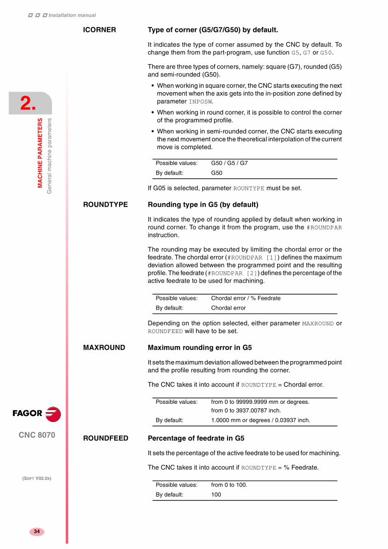
Installation manual
111
CNC 8070
2.
MA
CH
INE
PA
RA
ME
TE
RS
Gen
eral
mac
hine
par
amet
ers
(SOFT V02.0X)
34
ICORNER Type of corner (G5/G7/G50) by default.
It indicates the type of corner assumed by the CNC by default. Tochange them from the part-program, use function G5, G7 or G50.
There are three types of corners, namely: square (G7), rounded (G5)and semi-rounded (G50).
• When working in square corner, the CNC starts executing the nextmovement when the axis gets into the in-position zone defined byparameter INPOSW.
• When working in round corner, it is possible to control the cornerof the programmed profile.
• When working in semi-rounded corner, the CNC starts executingthe next movement once the theoretical interpolation of the currentmove is completed.
If G05 is selected, parameter ROUNTYPE must be set.
ROUNDTYPE Rounding type in G5 (by default)
It indicates the type of rounding applied by default when working inround corner. To change it from the program, use the #ROUNDPARinstruction.
The rounding may be executed by limiting the chordal error or thefeedrate. The chordal error (#ROUNDPAR [1]) defines the maximumdeviation allowed between the programmed point and the resultingprofile. The feedrate (#ROUNDPAR [2]) defines the percentage of theactive feedrate to be used for machining.
Depending on the option selected, either parameter MAXROUND orROUNDFEED will have to be set.
MAXROUND Maximum rounding error in G5
It sets the maximum deviation allowed between the programmed pointand the profile resulting from rounding the corner.
The CNC takes it into account if ROUNDTYPE = Chordal error.
ROUNDFEED Percentage of feedrate in G5
It sets the percentage of the active feedrate to be used for machining.
The CNC takes it into account if ROUNDTYPE = % Feedrate.
Possible values: G50 / G5 / G7
By default: G50
Possible values: Chordal error / % Feedrate
By default: Chordal error
Possible values: from 0 to 99999.9999 mm or degrees.
from 0 to 3937.00787 inch.
By default: 1.0000 mm or degrees / 0.03937 inch.
Possible values: from 0 to 100.
By default: 100

Installation manual
CNC 8070
MA
CH
INE
PA
RA
ME
TE
RS
Gen
eral
mac
hine
par
amet
ers
2.
(SOFT V02.0X)
35
Arc center correction
CIRINERR Absolute radius errorCIRINFACT Percentage radius error
They set the conditions for correcting the center position in circularinterpolations. This function is controlled via program using functionsG264 and G265.
On circular interpolations, the CNC calculates the radius of thestarting point and end point of the tool path. Theoretically, they shouldbe the same; but these parameters may be used to set the maximumdifference allowed between both radius.
Parameter CIRINERR indicates the maximum absolute error allowed.
Parameter CIRINFACT indicates the maximum relative error allowed(% of the radius).
Both parameters are taken into account. The CNC will show therelevant error message when this difference between them is greaterthan CIRINERR and greater than (CIRINFACT x Radius).
Feedrate override
MAXOVR Maximum axis override (%)
It indicates the maximum percentage to be applied to the programmedaxis feedrate (feedrate override).
The percentage applied to the programmed feedrate may be set byprogram, via PLC or by the %FEED switch of the panel. The one setby program has the highest priority and the one set by the switch hasthe lowest priority.
Different values may be set for each axis via PLC and by program. Theone selected at the switch is common to all of them.
Possible values: from 0 to 99999.9999 mm or degrees.
from 0 to 3937.00787 inch.
By default: 0.0100 mm or degrees / 0.00039 inch.
Possible values: from 0 to 100.0 %.
By default: 0.1 %.
Possible values: from 0 to 255.
By default: 200

Installation manual
111
CNC 8070
2.
MA
CH
INE
PA
RA
ME
TE
RS
Gen
eral
mac
hine
par
amet
ers
(SOFT V02.0X)
36
RAPIDOVR Override acts in G00 (from 0 to 100%)
It indicates whether the feedrate % may be modified (between 0% and100%) or not when working in G0. If not allowed, the percentage willstay fixed at 100%.
Regardless of the value assigned to this parameter, the overridealways attends to the 0% position and never acts over 100%. It isalways possible to change the % of feedrate when moving in jog mode.
FEEDND Apply the programmed feedrate to all the axes of thechannel
It indicates whether the programmed feedrate is applied to all the axesof the channel or only to the main axes.
FEEDND = YES
The programmed feedrate will be the result of composing themovements onto all the axes of the channel.
FEEDND = NO
If a movement has been programmed on any of the main axes, theprogrammed feedrate will be the result of composing the feedrate ontothese axes. The rest of the axes move at their corresponding feedrateto end the movement of them all at the same time.
The programmed feedrate is limited only if an axis could exceed itsMAXFEED. If none of the main axes are programmed, the programmedfeedrate will be reached on the axis moving the farthest so they canall reach their destination at the same time.
IMOVEMACH Movement of the independent axis referred to machinecoordinates
It indicates whether the movements of the independent axes arereferred to machine coordinates (IMOVEMACH = YES) or to partcoordinates (IMOVEMACH = NO), be fore the coord inatetransformations.
Possible values: Yes / No.
By default: Yes
Possible values: Yes / No.
By default: No.
Possible values: Yes / No.
By default: No.

Installation manual
CNC 8070
MA
CH
INE
PA
RA
ME
TE
RS
Gen
eral
mac
hine
par
amet
ers
2.
(SOFT V02.0X)
37
Related to subroutines
OEM subroutines
OEM subroutines are those associated with T, G74 and G180-G189functions
These subroutines must always be in the directory C:\CNC8070 \MTB\SUB. If they are not in this directory, an error message will be issued:
User subroutines
Are those subroutines associated with the programs.
These subroutines may be located anywhere. When calling any ofthese subroutines using the instructions: #PCALL, #CALL, etc withoutindicating the path, it will look for them in this order and in the followingdirectories:
1. Directory selected using the #PATH instruction.
2. Directory of the program being executed.
3. Directory indicated in the machine parameter SUBPATH.
When the call indicates the whole path, it will only look for it in theindicated directory.
SUBTABLE OEM-subroutines table
It shows the parameters that define the OEM subroutines associatedwith functions T, G74 and G180-G189. These subroutines mustalways be in the directory C:\CNC8070 \MTB \SUB.
TOOLSUB REFPSUB OEMSUB
TOOLSUB Name of the subroutine associated with T
This subroutine is executed automatically every time a T function (toolselection) is executed.
REFPSUB (G74) Subroutine associated with function G74
Function G74 (home search) may be programmed in two ways:indicating the axes and the order they will be homed or byprogramming G74 alone (without axes).
When executing a block containing the G74 function alone (withoutaxes), the CNC calls the subroutine indicated in this parameter. Thissubroutine must contain the home searches and the desired order.
This subroutine is also called when homing the axis in JOG modewithout selecting the axes.
Possible values: any text with up to 64 characters.
Possible values: any text with up to 64 characters.

Installation manual
111
CNC 8070
2.
MA
CH
INE
PA
RA
ME
TE
RS
Gen
eral
mac
hine
par
amet
ers
(SOFT V02.0X)
38
OEMSUB (G18x) Subroutines associated with functions G180 through G189
They indicate the number of the subroutines associated with functionsG180 through G189. Every time one of these functions is executed,its associated subroutine is called upon.
SUBPATH Path of program subroutines
It indicates the directory, by default, containing the user subroutines.
Tabletop probe position
PROBEDATA Channel related probe parameters
It shows the parameters needed to define the position of the tabletopprobe.
PRB1MAX PRB2MAX PRB3MAX
PRB1MIN PRB2MIN PRB3MIN
Besides these parameters, it is also necessary to configure the probesignals. See "Probe setting" on page 25.
PRB1MAX Maximum probe coordinate (abscissa axis)PRB1MIN Minimum probe coordinate (abscissa axis)PRB2MAX Maximum probe coordinate (ordinate axis)PRB2MIN Minimum probe coordinate (ordinate axis)PRB3MAX Maximum probe coordinate (axis perpendicular to the
plane)PRB3MIN Minimum probe coordinate (axis perpendicular to the
plane)
They define the position of the tabletop probe used for tool calibration.
Possible values: any text with up to 64 characters.

Installation manual
CNC 8070
MA
CH
INE
PA
RA
ME
TE
RS
Gen
eral
mac
hine
par
amet
ers
2.
(SOFT V02.0X)
39
They must be defined in absolute coordinates referred to machinereference zero. For a LATHE model CNC, the coordinates must begiven in radius.
Possible values: within ±99999.9999 mm.
within ±3937.00787 inch.
By default: 0
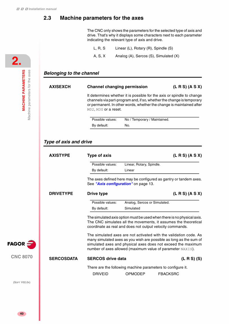
Installation manual
111
CNC 8070
2.
MA
CH
INE
PA
RA
ME
TE
RS
Mac
hine
par
amet
ers
for
the
axes
(SOFT V02.0X)
40
2.3 Machine parameters for the axes
The CNC only shows the parameters for the selected type of axis anddrive. That's why it displays some characters next to each parameterindicating the relevant type of axis and drive.
Belonging to the channel
AXISEXCH Channel changing permission (L R S) (A S X)
It determines whether it is possible for the axis or spindle to changechannels via part-program and, if so, whether the change is temporaryor permanent. In other words, whether the change is maintained afterM02, M30 or a reset.
Type of axis and drive
AXISTYPE Type of axis (L R S) (A S X)
The axes defined here may be configured as gantry or tandem axes.See "Axis configuration" on page 13.
DRIVETYPE Drive type (L R S) (A S X)
The simulated axis option must be used when there is no physical axis.The CNC simulates all the movements, it assumes the theoreticalcoordinate as real and does not output velocity commands.
The simulated axes are not activated with the validation code. Asmany simulated axes as you wish are possible as long as the sum ofsimulated axes and physical axes does not exceed the maximumnumber of axes allowed (maximum value of parameter NAXIS).
SERCOSDATA SERCOS drive data (L R S) (S)
There are the following machine parameters to configure it.
DRIVEID OPMODEP FBACKSRC
L, R, S Linear (L), Rotary (R), Spindle (S)
A, S, X Analog (A), Sercos (S), Simulated (X)
Possible values: No / Temporary / Maintained.
By default: No.
Possible values: Linear, Rotary, Spindle.
By default: Linear
Possible values: Analog, Sercos or Simulated.
By default: Simulated

Installation manual
CNC 8070
MA
CH
INE
PA
RA
ME
TE
RS
Mac
hine
par
amet
ers
for
the
axes
2.
(SOFT V02.0X)
41
DRIVEID Sercos drive address (L R S) (S)
It indica the position (node) the drive occupies in the Sercosconnection.
OPMODEP Sercos drive operation mode (L R S) (S)
It indicates the Sercos drive's operating mode. Velocity or feedbackcommand.
The axes (except tandem axes) should work in position-Sercos modeand the spindles should work in velocity-sercos mode. However,tandem axes must necessarily work in velocity-Sercos mode.
Refer to the drive manual for further detail.
FBACKSRC Type of feedback (L R S) (S)
Type of feedback used to close the position loop. When using internalfeedback, the position value is taken from motor feedback whereaswhen using external feedback, it is taken from direct feedback.
Refer to the drive manual for further detail.
Hirth axis
HIRTH Hirth axis (L R) (A S X)
A Hirth axis is the one that can only be position at positions multipleof a given value.
HPITCH Hirth axis pitch (L R) (A S X)
Possible values: from 1 to 16.
By default: 1
Possible values: Position / Speed.
By default: Position.
Possible values: Internal / External.
By default: Internal.
Possible values: Yes / No.
By default: No.
Possible values: from 0 to 99999.9999 mm or degrees.
within 0 and 3937.00787 inch.
By default: 0

Installation manual
111
CNC 8070
2.
MA
CH
INE
PA
RA
ME
TE
RS
Mac
hine
par
amet
ers
for
the
axes
(SOFT V02.0X)
42
Axis configuration for lathe type machines
FACEAXIS Face axis (lathe) (L) (A S X)LONGAXIS Longitudinal axis (lathe) (L) (A S X)
On turning machines, you must indicate which one is the longitudinalaxis and which one is the cross axis.
Typical lathe setting:
Typical Mill setting:
Rotary axes
AXISMODE Operating mode of the rotary axis (R) (A S X)
It indicates how the axis will behave in relation to the number of turnsand position display.
Behavior when AXISMODE = Module
It behaves like a rotary axis. The limits of the module must be positiveor zero, e.g. 0º to 360º, 0º to 400º or 95º -230º; not, for example, -100to -230º
Movements in G0/G1 and G90/G91 may be programmed.
• For movements in G90, it is possible to program more than one turnor values outside the module; but the whole travel must always beless than a full turn.
If the axis is neither SHORTESTWAY nor UNIDIR , the programmedsign will indicate the turning direction whereas the absolute valueof the coordinate will indicate the target position.
• For movements in G91, the programmed sign will indicate theturning direction whereas the absolute value of the coordinate willindicate the distance to move.
The coordinates are always displayed between the values set by theset parameters MODUPLIM and MODLOWLIM, by default 0 and 360º.See "Module definition in rotary axes and spindle" on page 75.
Parameters SHORTESWAY and UNIDIRmust be set. ParametersLIMIT+ and LIMIT- have no meaning
Possible values: Yes / No.
By default: No.
X axis FACEAXIS = Yes LONGAXIS = No
Z axis FACEAXIS = No LONGAXIS = Yes
Rest of axes FACEAXIS = No LONGAXIS = No
All the axes FACEAXIS = No LONGAXIS = No
Possible values: Linearlike, Module
By default: Module

Installation manual
CNC 8070
MA
CH
INE
PA
RA
ME
TE
RS
Mac
hine
par
amet
ers
for
the
axes
2.
(SOFT V02.0X)
43
Behavior when AXISMODE = Linearlike
It behaves like a linear axis. Movements in G0/G1 and G90/G91 maybe programmed.
The reading is free and in degrees (not affected by mm/inch). Thereare travel limits set by LIMIT+ and LIMIT-. See "Software axislimits" on page 46.
Parameters SHORTESWAY, UNIDIR and those for set MODUPLIM andMODLOWLIM do not apply.
UNIDIR Unidirectional rotation (R) (A S X)
It indicates whether the movements (G00/G01) in G90 of the rotaryaxes may be made in either direction or they must always rotate in thesame direction (positive or negative). If the axis is not UNIDIR , theprogrammed sign will indicate the turning direction whereas theabsolute value of the coordinate will indicate the target position.
The G91 movements are carried out in the programmed direction. Ifthe axis is UNIDIR, the programmed direction must coincide with theone preset for the axis; otherwise, the relevant error message will beissued because the axis cannot turn in the opposite direction.Likewise, the error will also come up when programming a mirrorimage on these axes.
The CNC takes it into account if AXISMODE = Module.
SHORTESTWAY Via shortest way (R) (A S X)
It indicates whether the linear axis movements in G00/G01 in G90of the rotary axes are carried out via the shortest way or not.Otherwise, the programmed sign will indicate the turning directionwhereas the absolute value of the coordinate will indicate the targetposition.
The G91 movements are carried out in the programmed direction.
The CNC takes it into account if AXISMODE = Module.
Possible values: No (both directions), Positive, Negative.
By default: No (both directions).
Possible values: Yes / No.
By default: No.
If starting at B0, a movement to B300 is programmed and then anotherone to B30.

Installation manual
111
CNC 8070
2.
MA
CH
INE
PA
RA
ME
TE
RS
Mac
hine
par
amet
ers
for
the
axes
(SOFT V02.0X)
44
Rotary axes and spindle
MODCOMP Module compensation (R S) (A Ss X)
It must be activated when the axis resolution is not exact. Rangeparameters MODNROT and MODERR set the compensation to beapplied to obtain the exact reading. See "Module definition in rotaryaxes and spindle" on page 75.
The CNC takes it into account if AXISMODE = Module.
CAXIS Works as a "C" axis (R S) (A S X)
It indicates whether the axis or spindle can work as a C axis or not.
CAXSET Work set for "C" axis (R S) (A S X)
It indicates which work set NPARSETS the axis uses when working as"C" axis.
The CNC takes it into account if CAXIS = Yes.
Spindle
AUTOGEAR Automatic gear change (S) (A S X)
It indicates whether the gear change is automatically generated byactivating (if necessary) the auxiliary functions M41, M42, M43 andM44 when programming the speed.
Possible values: Yes / No.
By default: No (without compensation).
Possible values: Yes / No.
By default: No.
Possible values: 1 to 4.
By default: 1
Possible values: Yes / No.
By default: No.

Installation manual
CNC 8070
MA
CH
INE
PA
RA
ME
TE
RS
Mac
hine
par
amet
ers
for
the
axes
2.
(SOFT V02.0X)
45
LOSPDLIM lower percentage for rpm OK (S) (A S X)UPSPDLIM Upper percentage for rpm OK (S) (A S X)
When working with M3 and M4, the REVOK signal is set to high (=1)when the actual spindle rpm are between these percentages.
The REVOK signal may be used to handle the Feedhold signal andavoid machining at lower or higher rpm than the ones programmed.
SPDLTIME Estimated time for an S function (S) (A S X)
In Editing - Simulation mode, there is an option that allows calculatingthe time required to execute a part with the machining conditionsestablished in the program.
To fine tune that calculation, one may define this parameter thatindicates the estimated time for processing the S function.
When assigning a value other than "0", the CNC interprets that the Svalue must be passed on to the PLC using signals SSTROBE + SFUN1.
SPDLSTOP M2, M30 and Reset stop the spindle (S) (A S X)
They indicate whether the execution of functions M2, M30or a resetstops the spindle or not. Otherwise, it will be necessary to programfunction M5.
SREVM05 G84. Reversal stops the spindle (S) (A S X)
It indicates whether the spindle must be stopped (with M5) whenreversing the spindle in tapping cycle.
Possible values: from 0 to 255.
By default: UPSPDLIM=150
LOSPDLIM=50
Possible values: from 0 to 1000000 ms.
By default: 0 ms.
Possible values: Yes / No.
By default: Yes.
Possible values: Yes / No.
By default: No.

Installation manual
111
CNC 8070
2.
MA
CH
INE
PA
RA
ME
TE
RS
Mac
hine
par
amet
ers
for
the
axes
(SOFT V02.0X)
46
STEPOVR Spindle Override step (S) (A S X)MINOVR Minimum spindle override (S) (A S X)MAXOVR Maximum spindle override (S) (A S X)
They set the incremental step used to override the spindle speedprogrammed with the Spindle Override keys of the operator panel. Italso sets the maximum and minimum values of the spindle override.
Software axis limits
LIMIT+ Positive software limit (L R) (A S X)LIMIT- Negative software limit (L R) (A S X)
On linear and rotary axes, they set the axis travel limits.
On rotary axes, they are only taken into account if AXISMODE =Linearlike.
If both are set to "0", the limits will be ignored, the axis may moveindefinitely in either direction.
SWLIMITTOL Software limits tolerance (L R) (A S X)
It indicates the maximum variation or oscillation allowed for an axislocated at the limit.
Runaway protection
TENDENCY Activation of tendency test (L R S) (A S)
It detects axis runaway due to positive feedback. It should be activatedduring machine setup.
Possible values: from 0 to 255.
By default: STEPOVR = 5
MINOVR = 50
MAXOVR = 150
Possible values: within ±99999.9999 mm or degrees.
within ±3937.00787 inch.
By default: Maximum values.
Possible values: from 0 to 99999.9999 mm or degrees.
within 0 and 3937.00787 inch
By default: 0.1000 mm or degrees (0.00394 inch).
Possible values: Yes / No.
By default: No.

Installation manual
CNC 8070
MA
CH
INE
PA
RA
ME
TE
RS
Mac
hine
par
amet
ers
for
the
axes
2.
(SOFT V02.0X)
47
PLC Offset
PLCOINC PLC offset increment per cycle (L R S) (A S X)
The CNC applies at all times the offset set by PLC. A typical utility isto correct the axis dilatations due to temperature.
This parameter indicates whether the PLC offset variations areassumed instantaneously or in steps.
Dwell for dead axes
DWELL Dwell for dead axes (L R S) (A S X)
When an axis has a brake, for example very heavy vertical axes, it isonly governed while it is moving. When it is governed by the CNC(movements), it is referred to as being alive and, when not moving(brake on), it is referred to as being "dead".
To bring it to "life", release the brake and close the position loop. Thetime required for this operation must be defined by the DWELLparameter.
Possible values: from 0 to 99999.9999 mm or degrees.
within 0 and 3937.00787 inch.
By default: 0 (they are assumed instantaneously).
Example:
It is set PLCOINC = 0.001mm (one micron per CNC cycle).
If the PLC Offset had an initial value of 0.25 mm and the new valueis 0.30 mm, the PLC Offset applied per cycle will be:
0.250 0.251 0.252 0.253 · · · · · 0.297 0.298 0.299 0.300
Possible values: within 0 and 1000000 ms.
By default: 0 (no dwell).
The ENABLE signal indicates to the PLC to let the axis move andthe SERVOON signal that the drive is ready.

Installation manual
111
CNC 8070
2.
MA
CH
INE
PA
RA
ME
TE
RS
Mac
hine
par
amet
ers
for
the
axes
(SOFT V02.0X)
48
Radius / diameter
DIAMPROG Programming in diameters (L) (A S X)
On turning machines, the coordinates of the cross axis may beprogrammed in either radius or diameter. To change the type ofcoordinates via program, use function G151 or G152.
The CNC takes it into account on axes if FACEAXIS = Yes.
Home search
REFDIREC Homing direction (L R S) (A S X)
DECINPUT Availability of a home switch (L R S) (A S)
Probe
PROBEAXIS Probing axis (L R) (A S X)
It indicates whether the axis is involved in a probing move (G100).
PROBERANGE Maximum braking distance (L R) (A S X)
It sets the maximum braking distance for the probe after probing toavoid breaking it (ceramic, etc). The CNC issues an error messageswhen this distance is exceeded.
Possible values: Yes / No.
By default: No
Possible values: Negative / Positive.
By default: Positive.
Possible values: Yes / No.
By default: Yes.
Possible values: Yes / No.
By default: No.
Possible values: from 0 to 99999.9999 mm or degrees.
within 0 and 3937.00787 inch.
By default: 1.0000 mm or degrees (0.03937 inch)

Installation manual
CNC 8070
MA
CH
INE
PA
RA
ME
TE
RS
Mac
hine
par
amet
ers
for
the
axes
2.
(SOFT V02.0X)
49
PROBEFEED Maximum probing feedrate (L R) (A S X)
It must be smaller than the feedrate needed to brake within thedistance set by PROBERANGE with the acceleration and jerk values ofthe axis. Otherwise, it will show a warning when validating the axisparameters indicating the maximum feedrate that may be reached.
PROBEDELAY Delay for the probe 1 signal (L R) (A S X)PROBEDELAY2 Delay for the probe 2 signal (L R) (A S X)
Parameter PROBEDELAY corresponds to the probe set by PRBID1 yPROBEDELAY2 to the probe set by PRBID2. See "Probe setting" onpage 25.
In some types of probes, there is a short delay of a few millisecondsfrom the probing instant to when the CNC actually receives the signals(infrared communication, etc.). In these cases, it must indicate thetime elapsed from when the probing takes place till the CNC receivesthe signal.
Probe calibration cycle #PROBE 2 may be used to set this parameter.After it is executed, the cycles returns, in arithmetic parameters P298and P299, the best value to be assigned to parameter PROBEDELAYfor the abscissa and ordinate axes.
Repositioning of the axes in tool inspection
REPOSFEED Maximum repositioning feedrate (L R) (A S X)
Repositioning feedrate after a tool inspection. If not defined, the CNCassumes asr repositioning feedrate the one defined for the jog mode(JOGFEED).
The value of parameter REPOSFEED must always be smaller thanG00FEED, MAXMANFEED and JOGRAPFEED.
Possible values: from 0 to 36000000.0000 mm/min or º/min.
from 0 to 1417322.83465 inch/min.
By default: 100.0000 mm/min o degrees/min.
3.93701 inch/min.
Possible values: within 0 and 65535 ms.
By default: 0 (no delay).
Possible values: from 0 to 200000.0000 mm/min or º/min.
from 0 to 7873.992 inch/min.
By default: 0

Installation manual
111
CNC 8070
2.
MA
CH
INE
PA
RA
ME
TE
RS
Mac
hine
par
amet
ers
for
the
axes
(SOFT V02.0X)
50
Independent axis
POSFEED Positioning feedrate (independent axis) (L R S) (A S X)
Positioning feedrate of the independent axis.
DSYNCVELW Velocity synchronization window (L R S) (A S X)
Maximum velocity difference allowed. When exceeded, it startscorrecting it.
DSYNCPOSW Position synchronization window (L R S) (A S X)
Maximum position difference allowed. When exceeded, it startscorrecting it.
Manual operating mode
MANUAL Manual (jog) operating mode parameters (L R) (A S X)
It shows the parameters for the Manual operating mode.
It is only available for axes, NOT for the spindle.
MANPOSSW Maximum positive travel with G201 (L R) (A S X)MANNEGSW Maximum negative travel with G201 (L R) (A S X)
When using function G201, Manual mode laid over the Automaticmode, they indicate how far the axis may be moved in both directions.
JOGFEED Continuous JOG mode feedrate (L R) (A S X)
Possible values: from 0 to 36000000.0000 mm/min or º/min.
from 0 to 1417322.83465 inch/min.
By default: 1000
Possible values: from 0 to 36000000.0000 mm/min or º/min.
from 0 to 1417322.83465 inch/min.
By default: 100
Possible values: from 0 to 36000000.0000 mm/min or º/min.
from 0 to 1417322.83465 inch/min.
By default: 0.0100 mm or degrees (0.00039 inch)
Possible values: within ±99999.9999 mm or degrees.
within ±3937.00787 inch.
By default: For MANPOSSW, the maximum positive value.
For MANNEGSW, the maximum negative value.
Possible values: from 0 to 200000.0000 mm/min or º/min.
from 0 to 7873.992 inch/min.
By default: 1000.0000 mm/min o degrees/min.
39.37008 inch/min.

Installation manual
CNC 8070
MA
CH
INE
PA
RA
ME
TE
RS
Mac
hine
par
amet
ers
for
the
axes
2.
(SOFT V02.0X)
51
JOGRAPFEED Continuous rapid JOG mode feedrate (L R) (A S X)MAXMANFEED Continuous maximum JOG mode feedrate (L R) (A S X)
MAXMANACC Maximum acceleration in JOG mode (L R) (A S X)
MANFEEDP Maximum % of jogging feedrate in G201 (L R) (A S X)IPOFEEDP Maximum % of execution feedrate in G201 (L R) (A S X)MANACCP Maximum % of jogging acceleration in G201 (L R) (A S X)IPOACCP Maximum % of execution acceleration in G201 (L R) (A S
X)
When using function G201, Manual mode laid over the Automaticmode, they indicate the maximum feedrate and acceleration used ineach mode.
The sum of both should not exceed 100 in order so as not to exceedthe dynamic limits of the machine under certain conditions.
It must be born in mind that when applying G201 while moving theaxes, the feedrate and the acceleration instantaneously assume thevalues set by IPOFEEDP and IPOACCP.
Possible values: from 0 to 200000.0000 mm/min or º/min.
from 0 to 7873.992 inch/min.
By default: 10000.0000 mm/min o degrees/min.
393.70079 inch/min.
Possible values: f rom 1.0000 to 1000000.0000 mm/s2 o rdegrees/s2.
from 0.03937 to 39370.07874 inch/s2.
By default: 1000.0000 mm/s2 or degrees/s2.
39.37008 inch/s2.
MANFEEDP % of MAXMANFEED as jogging feedrate limit.
IPOFEEDP % of G00FEED as execution feedrate limit.
MANACCP % of MAXMANACC as jogging acceleration limit.
IPOACCP % of ACCEL as execution acceleration limit.
Possible values: from 0 to 100.
By default: 20 (manual) and 80 (execution).

Installation manual
111
CNC 8070
2.
MA
CH
INE
PA
RA
ME
TE
RS
Mac
hine
par
amet
ers
for
the
axes
(SOFT V02.0X)
52
Manual operating mode. Handwheels
MPGRESOL Handwheel resolution (L R) (A S X)
It shows 3 parameters, one per each switch position. They indicatehow much the axis must move at each switch position (1, 10, 100) foreach handwheel pulse.
The most typical values are those set by default.
• For MPGRESOL1, 0.0010 mm or degrees.
• For MPGRESOL10, 0.0100 mm or degrees.
• For MPGRESOL100, 0.1000 mm or degrees.
Considering the following values for the Y axis:
G00FEED: 1000mm/min.
JOGFEED: 100mm/min.
MAXMANFEED: 120mm/min.
IPOFEEDP: 50%
MANFEEDP: 50%
When executing the following blocks:
N10 G201 #AXIS [Y]
N20 G1 Y100 F1000
At block N20, the maximum execution feedrate of the Y axis is not1000 mm/min (G00FEED), but 500 mm/min due to the 50% limitationof IPOFEED over G00FEED. Therefore, in spite of the programmedfeedrate "F1000", the axis will move at 500 mm/min due to thelimitation in G201.
If while the execution, the Y axis is moved via JOG panel, a 100mm/min feedrate (JOGFEED) should be added. However, themaximum jogging feedrate will be 60 min/min because it has beenlimited to 50% of MANFEEDP of MAXMANFEED.
Therefore, the Y axis will move at 560 mm/min when combining theautomatic and jog modes.
Possible values: from 0.0001 to 99999.9999 mm or degrees.
within 0.00001 and 3937.00787 inch.
Example
We have a graduated disk with 100 lines and we would like a feed of0.001 mm per line at position 1.
• With 100 line/turn handwheel, we have 1 pulse/line; thusMPGRESOL1 = 0.0010 mm.
• With 200 line/turn handwheel, we have 2 pulses/line; thusMPGRESOL1 = 0.0005 mm.
• With 25 line/turn handwheel, we have 1 pulse per 4 lines; thusMPGRESOL1 = 0.0040 mm.

Installation manual
CNC 8070
MA
CH
INE
PA
RA
ME
TE
RS
Mac
hine
par
amet
ers
for
the
axes
2.
(SOFT V02.0X)
53
MPGFILTER Filter time for the handwheel (L R) (A S X)
It smooths the handwheel movements avoiding sudden variations. Itindicates the number of CNC cycles used to are the handwheel pulsesread.
Manual operating mode. Incremetal JOG
INCJOGDIST Incremental jog distances (L R) (A S X)
It shows 5 parameters, one per each switch position. One must definethe distance traveled by each axis at each switch position (1, 10, 100,1000, 10000)
The most typical values are those set by default.
• For INCJOGDIST1, 0.0010 mm or degrees.
• For INCJOGDIST10, 0.0100 mm or degrees.
• For INCJOGDIST100, 0.1000 mm or degrees.
• For INCJOGDIST1000, 1.0000 mm or degrees.
• For INCJOGDIST10000, 10.0000 mm or degrees.
INCJOGFEED Incremental jog feedrates (L R) (A S X)
It shows 5 parameters, one per each switch position. One must definethe feedrate for each axis at each switch position (1, 10, 100, 1000,10000).
Leadscrew error compensation
LSCRWCOMP Leadscrew error compensation (L R S) (A S X)
LSCRWDATA Leadscrew compensation table (L R S) (A S X)
Each table has the following machine parameters to configure it.
NPOINTS BIDIR REFNEED
DATA
Possible values: from 1 to 1000.
By default: 10
Possible values: from 0.0001 to 99999.9999 mm or degrees.
within 0.00001 and 3937.00787 inch.
Possible values: from 0 to 200000.0000 mm/min or º/min.
from 0 to 7873.992 inch/min.
By default: 1000.0000 mm/min o degrees/min.
39.37008 inch/min.
Possible values: Yes / No.
By default: No.

Installation manual
111
CNC 8070
2.
MA
CH
INE
PA
RA
ME
TE
RS
Mac
hine
par
amet
ers
for
the
axes
(SOFT V02.0X)
54
NPOINTS Number of points of the table (L R S) (A S X)
The leadscrew error compensation table can have up to 1000 points.
TYPLSCRW Type of compensation (L R S) (A S X)
Determines whether the leadscrew error compensation will be appliedon to theoretical or real coordinates.
BIDIR Bi-directional compensation (L R S) (A S X)
It indicates whether the compensation is different for each direction
REFNEED Mandatory home search (L R S) (A S X)
It indicates whether the home search is necessary before applyingcompensation or not.
DATA Leadscrew error compensation at each point (L R S) (A S X)
At each point (LSCRWDATA) of the table, parameters POSITION,POSERROR and NEGERROR must be defined.
Parameter NEGERROR must be defined only with BIDIR = Yes.
Possible values: from 0 to 1000.
By default: 0 (there is no table).
Possible values: Real / Theoretical.
By default: Real
Possible values: Yes / No.
By default: No.
Possible values: Yes / No.
By default: No.

Installation manual
CNC 8070
MA
CH
INE
PA
RA
ME
TE
RS
Mac
hine
par
amet
ers
for
the
axes
2.
(SOFT V02.0X)
55
POSITION Position of each point (L R S) (A S X)POSERROR Error in the positive direction (L R S) (A S X)NEGERROR Error in the negative direction (L R S) (A S X)
Each parameter of the table represents a profile point to becompensated. The position that occupies the point in the profile willbe referred to machine zero.
When defining the various profile points in the table, the followingrequirements must be met.
• The points of the table must be ordered by their position on the axisand the table must begin by the most negative point (or leastpositive) to be compensated.
• For axis positioning outside this area, the CNC will apply thecompensation that was defined for the nearest end.
• The machine reference point must have "0" error.
Filters to eliminate resonance frequency
FILTER Filter table (L R S) (A S X)
Up to 3 different filters may be defined for each axis or spindle. Thefilters defined for the spindle will only be applied when it works as aC axis or it is doing a rigid tapping.
Using 3 different filters allows removing more than one resonancefrequency. Usually, a Low Passing filter or an "antiresonance" filter isused. Both filters may also be applied to the same axis or spindle whenthe resonance frequency is within the Low Passing bandwidth.
Each table has the following machine parameters to configure it.
ORDER TYPE FREQUENCY
When defining "antiresonance" type filters, parameters NORBWIDTHand SHARE must also be defined.
Possible values: within ±99999.9999 mm or degrees.
within ±3937.00787 inch.
By default: 0
In order to obtain a good part finish, it is recommended to set all theaxes that interpolate with each other with the same filter type and withthe same frequency.
i

Installation manual
111
CNC 8070
2.
MA
CH
INE
PA
RA
ME
TE
RS
Mac
hine
par
amet
ers
for
the
axes
(SOFT V02.0X)
56
ORDER Filter order (L R S) (A S X)
The down slop will be softened: the greater the number the steeperthe slope.
It is recommended to always define it with a value of 3 when a filteris to be applied. Before assigning another value, check with theService Department of Fagor Automation.
TYPE Type of filter (L R S) (A S X)
There are two types of f i l ters, namely, " low passing" and"antiresonance" (band-rejection, notch filter).
"Low passing" filter
The "low passing" filter is used to eliminate the Jerk smoothingmovements out although it has the drawback of slightly rounding thecorners off.
Antiresonance filter (band-rejection, notch filter)
The band-rejection filter (notch filter) must be used when the machinehas a resonance frequency to be removed.
Possible values: from 0 to 10
By default: 0 (No filter is applied).
Possible values: Low Passing and band-rejection (notch filter).
By default: Low Passing.

Installation manual
CNC 8070
MA
CH
INE
PA
RA
ME
TE
RS
Mac
hine
par
amet
ers
for
the
axes
2.
(SOFT V02.0X)
57
FREQUENCY Break or mid frequency (L R S) (A S X)
On a "Low Passing" filter, it indicates the break point frequency orfrequency where the amplitude drops 3 dB or it reaches 70% of thenominal amplitude.
-3dB = 20 log (A/Ao) ==> A = 0,707 Ao
On the band-rejection filter (notch filter), it indicates the centerfrequency or the frequency where the resonance reaches itsmaximum value.
NORBWIDTH Standard bandwidth (L R S) (A S X)
It is calculated with the following formula. f1 and f2 correspond to thebreak frequency where the amplitude drops 3 dB or it reaches 70%of the nominal amplitude.
-3dB = 20 log (A/Ao) ==> A = 0,707 Ao
The CNC takes it into account if TYPE = Antiresonance (notch filter).
SHARE % of signal going through the filter (L R S) (A S X)
It indicates the percentage of signal going through the filter. This valuemust be equivalent to the percentual overshooting of the resonancebecause it must compensate for it.
The CNC takes it into account if TYPE = Antiresonance (notch filter).
Example of a calculation for a particular response of the machine.
Possible values: from 0 to 500.0
By default: 30.0
Possible values: from 0 to 100.0
By default: 1.0
NORBWIDTH FREQUENCYf2 f1–( )
--------------------------------------=
Possible values: from 0 to 100.
By default: 100.
SHARE=100(Ar-Ao)/Arfr
f
A
Ar
Ao

Installation manual
111
CNC 8070
2.
MA
CH
INE
PA
RA
ME
TE
RS
Mac
hine
par
amet
ers
for
the
axes
(SOFT V02.0X)
58
Work sets
NPARSETS Number of parameter sets (L R S) (A S X)
Up to 4 different ranges may be defined to indicate the dynamics ofthe axis in each one of them (feedrates, gains, accelerations, etc.).
DEFAULTSET Default work set (L R S) (A S X)
It indicates the set assumed by the CNC on power-up, after executingan M02 or M30 or after a Reset.
When defined with a "0" value, the set is always maintained.
To select a set via part-program, use function G112.
On spindles, function G112 selects the set but it does not carry out agear change. To select a set and make a gear change, use functionsM41 through M44.
Possible values: 1 to 4.
By default: 1
Possible values: 0 to 4.
By default: 1

Installation manual
CNC 8070
MA
CH
INE
PA
RA
ME
TE
RS
Mac
hine
par
amet
ers
for
the
axes
2.
(SOFT V02.0X)
59
2.3.1 Machine parameters for the axes. Work sets
Up to 4 different ranges may be defined to indicate the dynamics ofthe axis in each one of them (feedrates, gains, accelerations, etc.).See "Work sets" on page 58.
Each set only shows the parameters for the selected type of axis anddrive. That's why, there are some characters next to them indicatingtheir relevant type of axis and drive.
For Sercos drive, parameters
Resolution
PITCH Leadscrew pitch (L R S) (A S X)
PITCH2 Leadscrew pitch (2nd feedback) (L R S) (S)
• On a linear axis with a rotary encoder and leadscrew, it defines theleadscrew pitch.
• On a linear axis with a linear encoder (scale), it defines the pitchof the scale.
• On a rotary axis, it sets the number of degrees per turn of theencoder.
INPUTREV Turns of motor shaft (L R S) (A S X)
OUTPUTREV Turns of machine axis (L R S) (A S X)
It sets the gear ratio between the motor shaft and the final axis thatmoves the machine.
The possible gear ratio existing between the motor and the encodercan also be entered directly through parameter PITCH. In this case,parameters INPUTREV and OUTPUTREV must be set to ·1·.
L, R, S Linear (L), Rotary (R), Spindle (S)
A, S, X Analog (A), Sercos (S), Speed Sercos (Ss), Simulated(X)
Possible values: from 0 to 99999.9999 mm or degrees.
within 0 and 3937.00787 inch.
By default: 5 mm or degrees (0.19685 inch).
Example:
Axis with a 5 mm pitch leadscrew PITCH = 5 mm
Axis with a 20 µm pitch Fagor scale PITCH = 0.020 mm
Rotary axis with a 1/10 gear ratio PITCH = 36º
Possible values: from 1 to 32767.
By default: 1.

Installation manual
111
CNC 8070
2.
MA
CH
INE
PA
RA
ME
TE
RS
Mac
hine
par
amet
ers
for
the
axes
(SOFT V02.0X)
60
INPUTREV2 Turns of motor shaft (2nd feedback) (L R S) (S)
OUTPUTREV2 Turns of machine axis (2nd feedback) (L R S) (S)
It sets the gear ration when not using second feedback.
NPULSES Number of encoder pulses (L R S) (A Ss X)
NPULSES2 Number of encoder (2nd feedback) pulses (L R S) (A Ss X)
Number of pulses per turn of the encoder. With linear encoder (scale)set NPULSES = 0 and NPULSES2 = 0.
When using a gear reduction on the axis, the whole assembly mustbe taken into account when defining the number of pulses per turn.
SINMAGNI Sinusoidal multiplying factor (L R S) (A X)
It indicates the multiplying factor applied to the sinewave feedback ofthe axis.
For square feedback signals, set SINMAGNI = 0. The CNC applies ax4 factor.
ABSFEEDBACK Absolute feedback system (L R S) (A S X)
FBACKAL Feedback alarm activation (L R S) (A)
Possible values: from 1 to 32767.
By default: 1.
Possible values: from 0 to 65535.
By default: 1250
Possible values: from 0 to 255.
By default: 0
Possible values: Yes / No.
By default: No.
Possible values: Yes / No.
By default: No.

Installation manual
CNC 8070
MA
CH
INE
PA
RA
ME
TE
RS
Mac
hine
par
amet
ers
for
the
axes
2.
(SOFT V02.0X)
61
Loop setting
LOOPCH Analog voltage sign change (L R S) (A S X)AXISCH Feedback sign change (L R S) (A S X)
If the axis runs away, the CNC issues a following error message.Change the value of parameter LOOPCHG
If it does not run away, but the counting direction is not the desired one,change the values of both parameters AXISCHG and LOOPCHG.
INPOSW In position zone (L R S) (A S X)
The in-position zone is defined as the zone before and after theprogrammed position where the axis is considered to be in position.Parameter INPOSW defines the width of both zones.
Backlash compensation in movement reversal
BACKLASH Backlash (L R S) (A S X)
When an axis has backlash and reverses its moving direction, thereis a delay from the instant the motor starts turning to the moment whenthe axis actually moves. This usually happens on axes with encoderand on old machines whose leadscrew assembly is defective (wornout).
Use a dial indicator to measure this backlash. Move the axis in onedirection and set the dial indicator to 0. Move the axis in the oppositedirection in incremental mode until detecting that the axis moves. Theamount of backlash is the difference between the commandeddistance and what it actually moved.
With linear encoders (scales), set BACKLASH = 0
Possible values: Yes / No.
By default: No.
Possible values: from 0.0001 to 99999.9999 mm or degrees.
within 0.00000 and 3937.00787 inch.
By default: 0.0100 mm or degrees (0.00039 inch).
Possible values: within ±3.2768 mm or degrees (±0.12901 inch).
By default: 0

Installation manual
111
CNC 8070
2.
MA
CH
INE
PA
RA
ME
TE
RS
Mac
hine
par
amet
ers
for
the
axes
(SOFT V02.0X)
62
Backlash compensation with additional command pulse
BAKANOUT Additional command pulse (L R S) (A S)
Additional velocity command pulse to make up for the possibleleadscrew backlash when reversing the moving direction. Every timethe movement is inverted, the CNC will apply to that axis the velocitycommand corresponding to the movement plus the additional velocitycommand pulse set in this parameter.
This additional command will be applied for the time period indicatedby (a.m.p.) BAKTIME.
With an analog drive, the additional velocity command is given in unitsof the D/A converter with an integer between 0 and 32767. 10 Vcorrespond to the value of 32767.
When setting an additional command pulse, parameters BAKTIMEand ACTBAKANmust also be set.
BAKTIME Duration of the additional command pulse (L R S) (A S)
It indicates the duration of the additional velocity command pulse tomake up for backlash in movement reversals.
ACTBAKAN Application of the additional command pulse(L R S) (A S)
It determines when the additional command pulse is applied tocompensate for backlash peaks.
Possible values: With analog drive, between 0 and 32767.
With Sercos drive, within ±1000 rpm.
By default: 0 (Not applied).
BAKANOUT 1 3277 32767
Analog voltage 0.3 mV 1 V 10 V
Possible values: from 0 to 65535.
By default: 0
Possible values: Always.
G2 / G3.
By default: Always.

Installation manual
CNC 8070
MA
CH
INE
PA
RA
ME
TE
RS
Mac
hine
par
amet
ers
for
the
axes
2.
(SOFT V02.0X)
63
Feedrate setting
G00FEED Feedrate in G00 (L R S) (A S X)
Rapid positioning (traverse, G00) are always carried out at themaximum speed possible. The one indicated by G00FEED.
MAXVOLT Analog voltage to reach G00FEED (L R S) (A Ss)
This is the analog voltage the CNC must output so the axis can reachits maximum rapid traverse feedrate G00FEED.
Gain setting
PROGAIN Proportional gain (L R S) (A S X)
It sets the following error "ε" (difference between the theoreticalinstantaneous position and the actual - real - axis position) for aparticular feedrate.
Possible values: from 0 to 200000.0000 mm/min, degrees/min.
from 0 to 7873.992 inch/min.
from 0 to 100000.0000 rpm.
By default: 10000.0000 mm/min, degrees/min or rpm.
393.70079 inch/min.
from 0 to 3000.0000 rpm.
Possible values: from 0 to 10000.0000 mV.
By default: 9500 mV (9.5 V).
Possible values: de 0.0 a 100.0 (1000/min).
By default: 1
Each square of this graph represents a following error "ε" of 800 µm.
Example:
To obtain a following error (axis lag) of 1 mm for a feedrate of 1000mm/min. (a gain of 1):
Feedrate = Following error x PROGAIN
Feedrate / "ε" = 1000 (mm/min) / 1 (mm) = 1000 / min
PROGAIN = 1
Actual FeedFollowing Error (ε)

Installation manual
111
CNC 8070
2.
MA
CH
INE
PA
RA
ME
TE
RS
Mac
hine
par
amet
ers
for
the
axes
(SOFT V02.0X)
64
FFWTYPE Pre-control type (L R S) (A S X)
FFGAIN Percentage of Feed-Forward in automatic (L R S) (A S X)
It helps improve the position loop minimizing the amount of followingerror "ε". It should only be used when working with non-linearacceleration and deceleration.
It sets the part of the analog output that is proportional to theprogrammed feedrate. The rest will be proportional to the followingerror "ε".
The CNC considers it when working with Feed Forward. ParameterFFWTYPE if it is an analog drive or simulated, and parameter OPMODEPif it is Sercos.
The best adjustment is achieved when minimizing the following erroras much as possible but without reaching negative values.
Possible values: OFF
Feed Forward
AC-Forward
Feed Forward + AC-Forward
By default: OFF
Possible values: from 0 to 120 (%).
By default: 0
(A) Proper adjustment with Feed-forward.
(B) Wrong adjustment with Feed-forward.
Each square of this graph represents a following error "ε" of 10 µm.
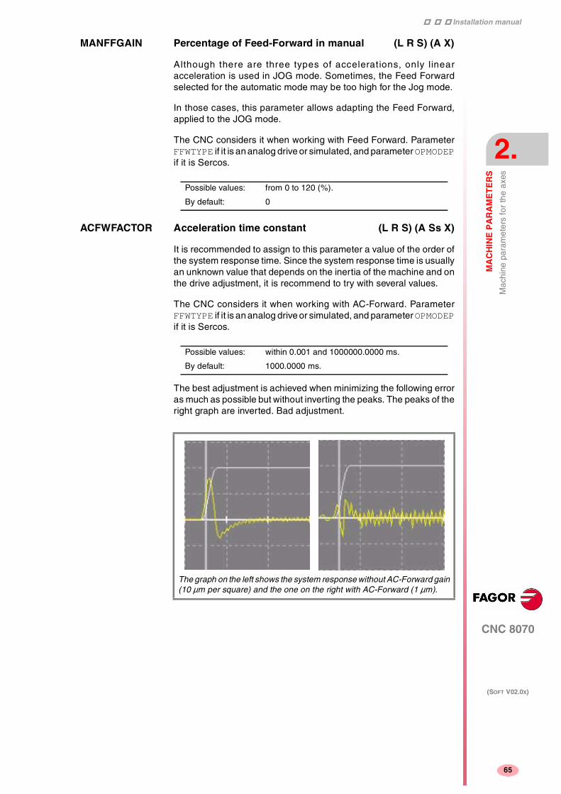
Installation manual
CNC 8070
MA
CH
INE
PA
RA
ME
TE
RS
Mac
hine
par
amet
ers
for
the
axes
2.
(SOFT V02.0X)
65
MANFFGAIN Percentage of Feed-Forward in manual (L R S) (A X)
Although there are three types of accelerations, only linearacceleration is used in JOG mode. Sometimes, the Feed Forwardselected for the automatic mode may be too high for the Jog mode.
In those cases, this parameter allows adapting the Feed Forward,applied to the JOG mode.
The CNC considers it when working with Feed Forward. ParameterFFWTYPE if it is an analog drive or simulated, and parameter OPMODEPif it is Sercos.
ACFWFACTOR Acceleration time constant (L R S) (A Ss X)
It is recommended to assign to this parameter a value of the order ofthe system response time. Since the system response time is usuallyan unknown value that depends on the inertia of the machine and onthe drive adjustment, it is recommend to try with several values.
The CNC considers it when working with AC-Forward. ParameterFFWTYPE if it is an analog drive or simulated, and parameter OPMODEPif it is Sercos.
The best adjustment is achieved when minimizing the following erroras much as possible but without inverting the peaks. The peaks of theright graph are inverted. Bad adjustment.
Possible values: from 0 to 120 (%).
By default: 0
Possible values: within 0.001 and 1000000.0000 ms.
By default: 1000.0000 ms.
The graph on the left shows the system response without AC-Forward gain(10 µm per square) and the one on the right with AC-Forward (1 µm).

Installation manual
111
CNC 8070
2.
MA
CH
INE
PA
RA
ME
TE
RS
Mac
hine
par
amet
ers
for
the
axes
(SOFT V02.0X)
66
ACFGAIN Percentage of AC-Forward in automatic (L R S) (A S X)MANACFGAIN Percentage of AC-Forward in JOG mode (L R S) (A X)
They are similar to parameters FFGAIN and MANFFGAIN; but theyaffect the AC-Forward. They improve the system response toacceleration changes. They minimize the amount of following error "ε"on start-ups, braking and direction reversals.
The CNC considers it when working with AC-Forward. ParameterACFWFACTOR.
Linear acceleration
The type of acceleration is defined with parameter SLOPETYPE. See"Channel's default conditions" on page 30.
1. The axis starts moving with the acceleration indicated in LACC1and maintains that acceleration until reaching the feedrateindicated in LFEED.
2. From that instant on, it keeps moving with the accelerationindicated in LACC2.
3. When reaching the programmed feedrate, the acceleration goesback to "0".
4. When braking, it decelerates with the value indicated in LACC2.
5. When the feedrate is lower than the one indicated in LFEED, itdecelerates with the value of LACC1.
Possible values: from 0 to 120 (%)
By default: 0

Installation manual
CNC 8070
MA
CH
INE
PA
RA
ME
TE
RS
Mac
hine
par
amet
ers
for
the
axes
2.
(SOFT V02.0X)
67
LACC1 Acceleration of the first section (L R S) (A S X)LACC2 Acceleration of the second section (L R S) (A S X)
LFEED Change speed (L R S) (A S X)
Trapezoidal and square sine accelerations
Trapezoidal acceleration may be used to program ramps in order tosmooth out the acc/dec changes.
Square-sine acceleration is an improved trapezoidal acceleration. Itsmooths out the jerk so the movements are softer and the axismechanics suffers less.
The figure below shows the graphs for velocity (v), acceleration graph(a) and jerk (j) for each case.
Possible values: f rom 1.0000 to 1000000.0000 mm/s2 o rdegrees/s2.
from 0.03937 to 39370.07874 inch/s2.
By default: 1000.0000 mm/s2 or degrees/s2.
39.37008 inch/s2.
Possible values: from 0 to 200000.0000 mm/min, degrees/min.
from 0 to 7873.992 inch/min.
from 0 to 100000.0000 rpm.
By default: 1000.0000 mm/min, degrees/min or rpm.
39.37008 inch/min.
from 0 to 10000.0000 rpm.

Installation manual
111
CNC 8070
2.
MA
CH
INE
PA
RA
ME
TE
RS
Mac
hine
par
amet
ers
for
the
axes
(SOFT V02.0X)
68
The dynamics of both accelerations are similar and they are definedusing the same parameters. We now show the dynamics of thetrapezoidal acceleration.
1. The axis starts moving with a uniformly increasing acceleration,with a slope limited by ACCJERK, until reaching the accelerationindicated in ACCEL.
2. The acceleration becomes constant at the ACCEL value.
3. Before reaching the programmed feedrate, there is a decelerationlimited by ACCJERK.
4. It goes on at the programmed feedrate and with no acceleration.
5. To slow down or stop the axis, a uniformly decreasing decelerationis applied with a slope limited by DECJERK.
6. The deceleration becomes constant at the DECEL value.
7. Before reaching the programmed feedrate, or stopping, there is adeceleration limited by DECJERK.
ACCEL Acceleration (L R S) (A S X)DECEL Deceleration (L R S) (A S X)
ACCJERK Acceleration Jerk (L R S) (A S X)DECJERK Acceleration Jerk (L R S) (A S X)
Possible values: f rom 1.0000 to 1000000.0000 mm/s2 ordegrees/s2.
from 0.03937 to 39370.07874 inch/s2.
By default: 1000.0000 mm/s2 or degrees/s2.
39.37008 inch/s2.
Possible values: from 1.0000 to 1000000000.0000 mm/s3 ordegrees/s3.
from 0.03937 to 39370.078.74010 inch/s3.
By default: 10000.000 mm/s3 or degrees/s3.
393.70087 inch/s3.

Installation manual
CNC 8070
MA
CH
INE
PA
RA
ME
TE
RS
Mac
hine
par
amet
ers
for
the
axes
2.
(SOFT V02.0X)
69
Home search
Feedback system with distance-coded reference marks (I0)
Axes whose feedback system offers distance-coded reference marks(coded I0) may be referenced (homed) at any point of the machine.
The axis moves the minimum distance possible, less than 200 mm,in the direction set by general axis parameter "REFDIREC" and at thefeedrate indicated in "REFEED2".
Feedback system without distance-coded reference marks (I0)
When the feedback system does not have distance-coded referencemarks, the axis must always be homed at a specific point of themachine which is referred to as Machine Reference Point or Home.
The installer must place a home switch for each axis at the MachineReference Point.
The axis moves in the direction set by axis parameter "REFDIREC" andat the feedrate indicated by "REFEED1" until reaching the homeswitch.
When pressing the home switch, it reverses and moves back at thefeedrate indicated by "REFEED2". It keeps on moving after releasingthe home switch until the CNC detects a marker pulse (I0) from thefeedback device.
The Machine Reference Point must also be set when the feedbacksystem has distance-coded reference marks (I0) and leadscrew errorcompensation is being applied on to that axis.
The home search may be carried out anywhere on the machine; butthe leadscrew error at the machine reference point (home) point mustbe "0".
I0TYPE Type of reference mark (I0) (L R S) (A S X)
Fagor linear encoders with increasing distance-coded I0
MOVX, MOVY, MOVP, FOX, FOP
Fagor linear encoders with decreasing distance-coded I0
COVX, COVP.
Possible values: Incremental (Not distance-coded)
Increasing distance-coded
Decreasing distance-coded
By default: Incremental (Not distance-coded)

Installation manual
111
CNC 8070
2.
MA
CH
INE
PA
RA
ME
TE
RS
Mac
hine
par
amet
ers
for
the
axes
(SOFT V02.0X)
70
REFVALUE Position of the reference point (L R S) (A S X)
The Machine Reference Point (home) must be defined when:
• The feedback system does not have distance-coded marks (I0)
• The feedback system has distance-coded marks (I0) andleadscrew error compensation is being applied on that axis.
Set the home position referred to Machine Reference Zero.
REFSHIFT Offset of the reference point (L R S) (A S X)
Sometimes, to readjust the machine, it is necessary to take down thefeedback device, thus when putting back up, the new home point mightno coincide with the previous one.
Since the home point must still be the same, the difference betweenthe new point and the old point must be assigned to parameterREFSHIFT .
REFFEED1 Fast home searching feedrate (L R S) (A S X)REFFEED2 Slow home searching feedrate (L R S) (A S X)
When the feedback system does not have distance-coded referencemarks (I0), the home search is carried out at the feedrate indicatedby "REFEED1" until the home switch is reached. It then reverses itsmovement at the feedrate indicated by REFEED2 and it goes on untilthe CNC receives the reference marker pulse from the feedbackdevice.
REFPULSE Type of I0 pulse (L R S) (A S X)
It indicates the type of flank of the I0 signal that is used for homesearch.
Possible values: within ±99999.9999 mm or degrees.
within ±3937.00787 inch.
By default: 0
Possible values: within ±99999.9999 mm or degrees.
within ±3937.00787 inch.
By default: 0
Possible values: from 0 to 200000.0000 mm/min, degrees/min.
from 0 to 7873.992 inch/min.
from 0 to 100000.0000 rpm.
By default:
REFFEED1: 1000.0000 mm/min or degrees/min (39.37001inch/min) or 100.000 rpm.
REFFEED2: 100.0000 mm/min or degrees/min (3.93700 inch/min)or 10.000 rpm.
Possible values: Positive / negative.
By default: Positive.

Installation manual
CNC 8070
MA
CH
INE
PA
RA
ME
TE
RS
Mac
hine
par
amet
ers
for
the
axes
2.
(SOFT V02.0X)
71
ABSOFF Offset referred to the distance-coded I0 (L R S) (A S X)
The CNC takes it into account if I0TYPE = Distance coded.
With linear encoders with distance-coded (I0) reference marks, it ispossible to know the position of the machine by simply moving the axisa distance of 20 or 100 mm.
After reading two consecutive distance-coded (I0)reference marks (20or 100 mm away from each other, it is possible to know the axis positionwith respect to the zero point of the graduated glass (C).
In order for the CNC to show the position with respect to Machine Zero(M), this parameter must be assigned the position of the machine zero(M) with respect to the glass zero point (C).
The zero point of the glass (beginning of the distance code) may bein or out the scale's measuring length.
EXTMULT External factor for distance-coded mark (L R S) (A X)
The CNC takes it into account if I0TYPE = Distance coded.
It indicates the relationship between the mechanical period (of thegraduation on the glass) and the electrical period (of the feedbacksignal) being applied to the CNC.
Values to be assigned for Fagor encoders with distance-coded I0.
Possible values: within ±99999.9999 mm or degrees.
within ±3937.00787 inch.
By default: 0
Example with a Fagor linear encoder.
A "FOX" type Fagor linear encoder has a graduation period of 100µm (gap between lines) and an electrical signal period of 4 µm.
EXTMULT = 100 / 4 = 25
Possible values: from 0 to 256.
By default: 0
Rotary encoder EXTMULT
HO SO 90,000 pulses 5
HO SO 180,000 pulses 10
HOP SOP 18,000 pulses 1

Installation manual
111
CNC 8070
2.
MA
CH
INE
PA
RA
ME
TE
RS
Mac
hine
par
amet
ers
for
the
axes
(SOFT V02.0X)
72
I0CODDI1 Gap between two fixed distance-coded I0's(L R S) (A S X)I0CODDI2 Gap between two variable distance-coded I0's(L R S) (A S X)
The CNC takes it into account if I0TYPE = Distance coded.
It is defined in number of waves.
Values to be assigned for Fagor encoders with distance-coded I0.
Linear encoder EXTMULT
SOP
SVOP
GOP MOP
MOC
MOT
MOVP
COP
COC
COT
COVP
1
SOX
SVOX
GOX MOX COX 2
MOY
MOVY
COY 10
LOP 1
LOX 10
MOVX COVX FOT 5
FOX 25
FOP 1
Possible values: from 0 to 65535.
By default: I0CODD1=1000 and I0CODD2=1001.
Example with a Fagor linear encoder.
Gap between two fixed distance-coded I0's
20.000 mm
Gap between two variable distance-coded I0's
20.020 mm
Period of the sinewave signal 20 mm
Number of waves between fixed I0's 20000/(20 x EXTMULT) = 1000
Number of waves between variableI0's
20020/(20 x EXTMULT) = 1001
Linear encoder I0CODDI1 I0CODDI2
SOP
SVOP
GOP MOP
MOC
MOT
MOVP
COP
COC
COT
COVP
1000 1001
SOX
SVOX
GOX MOX COX 1000 1001
MOY
MOVY
COY 1000 1001

Installation manual
CNC 8070
MA
CH
INE
PA
RA
ME
TE
RS
Mac
hine
par
amet
ers
for
the
axes
2.
(SOFT V02.0X)
73
Following error
Following error is the difference between the theoretical position andthe actual (real) position of the axis.
The following error decreases when increasing the axis gain.
The more similar (identical) the following errors of interpolating axesare, the better the machining of curved sections will be on circularinterpolations.
FLWEMONITOR Type of monitoring (L R S) (A S X)
MINFLWE Maximum following error when stopped (L R S) (A S)
It indicates the maximum amount of following error allowed when theaxis is stopped.
The CNC takes it into account if FLWEMONITOR other than "Off".
The MINFLWE value cannot be greater than 1/4 of the total axis travel(LIMITPOS - LIMITNEG).
LOP 2000 2001
LOX 2000 2001
MOVX COVX FOT 1000 1001
FOX 1000 1001
FOP 1000 1001
Rotary encoder I0CODDI1 I0CODDI2
HO SO 90,000 pulses 1000 1001
HO SO 180,000 pulses 1000 1001
HOP SOP 18,000 pulses 1000 1001
Linear encoder I0CODDI1 I0CODDI2
Possible values: Off, Standard, Linear.
Off: The following error is not monitored, thus no error message willbe issued.
Standard: The following error is monitored all the time and an errormessage will be issued when it exceeds the value of parametersMAXFLWE and MINFLWE.
Linear: It is a dynamic monitoring that allows for a percentualfollowing error. This percentage is set by parameter FEDYNFACT.
By default: Off (no monitoring)
Possible values: from 0 to 99999.9999 mm or degrees.
within 0 and 3937.00787 inch.
By default: 1.0000 mm or degrees (0.03937 inch).

Installation manual
111
CNC 8070
2.
MA
CH
INE
PA
RA
ME
TE
RS
Mac
hine
par
amet
ers
for
the
axes
(SOFT V02.0X)
74
MAXFLWE Maximum following error in motion (L R S) (A S)
The CNC takes it into account if FLWEMONITOR other than "Off".
• With FLWEMONITOR = Standard, it indicates the maximum amountof following error allowed when the axis is moving.
• With FLWEMONITOR = Linear, it indicates the value starting atwhich the following error is dynamically monitored.
FEDYNAC % of following error deviation (L R S) (A S)
The CNC takes it into account if FLWEMONITOR = Linear. It indicatesthe permitted percentage error, deviation of the real following errorwith respect to the theoretical one.
The CNC calculates the maximum and minimum following error (Fe)at all times depending on feedrate (F). If is not within the permittedzone (shaded area of the figure) , the CNC will issue the relevant errormessage.
Parameter MAXFLWE indicates the value starting at which the followingerror will be dynamically monitored.
ESTDELAY Following error delay (L R S) (A S)
This parameter is used to define a delay applied when estimating thefollowing error so the theoretical value (1) comes closer to the real one(2) thus avoiding undesired following error messages.
Possible values: from 0 to 99999.9999 mm or degrees.
within 0 and 3937.00787 inch.
By default: 1.0000 mm or degrees (0.03937 inch).
Possible values: from 0 to 100 (%).
By default: 50
Possible values: within 0 and 1000000 ms.
By default: 0
Installation manual
CNC 8070
MA
CH
INE
PA
RA
ME
TE
RS
Mac
hine
par
amet
ers
for
the
axes
2.
(SOFT V02.0X)
75
INPOMAX Time to get in position (L R S) (A S X)INPOTIME Minimum in position time (L R S) (A S X)
Parameter INPOMAX limits (maximum time) the time the axis needsto get in position.
Parameter INPOTIME sets the time the axis must stay in the in-position zone so the CNC considers it to be "in position".
They ensure that when working with dead axes (axes only controlledwhile moving), the movement will be completed when they are inposition.
Axis lubrication
DISTLUBRI Distance for lubrication pulse (L R S) (A S X)
The lubrication signal is activated after travelling the distanceindicated in this parameter.
The PLC reads this parameter in mm instead of doing it in tenths ofa micron (0.0001 mm).
The CNC logic inputs and outputs: LUBR(axis), LUBRENA(axis)and LUBROK(axis) must be used in order for the PLC lubricates theaxes and gears.
1. The LUBRENA(axis) mark indicates whether this feature is to beused or not.
2. When the axis has traveled the distance indicated by (a.m.p.)DISTLUBRI, the LUBR(axis) mark is set to "1" to "tell" the PLCthat the axis must be lubricated.
3. After lubricating the axis, the PLC sets the LUBROK(axis) markhigh (=1) to let the CNC know that the axis has been lubricated.
4. The CNC sets the LUBR(axis) mark low (=0) and resets its countto "0".
Module definition in rotary axes and spindle
MODUPLIM Module's upper limit (R S) (A Ss X)MODLOWLIM Module's lower limit (R S) (A Ss X)
The CNC takes them into account if (a.m.p.) AXISMODE = Module.
For a reading within ±180°, set MODUPLIM = 180º and MODLOWLIM =-180º.
Possible values: within 0 and 1000000 ms.
By default: 0
Possible values: from 0 to 2000000000 mm or degrees.
from 0 to 78739920 inch.
By default: 0 (no lubrication).
Possible values: within ±99999.9999º.
By default: MODUPLIM = 360º and MODLOWLIM = 0º.

Installation manual
111
CNC 8070
2.
MA
CH
INE
PA
RA
ME
TE
RS
Mac
hine
par
amet
ers
for
the
axes
(SOFT V02.0X)
76
MODNROT Module error. Turns (R S) (A Ss X)MODERR Module error. Increments (R S) (A Ss X)
The CNC takes them into account if (a.m.p.) AXISMODE = Module andMODCOMP = Yes.
They indicate the compensation to be applied to compensate for aninexact axis resolution.
Example:
A rotary axis having a gear ratio of 7/11 and a 1000 line encodermounted on the motor.
PITCH = 360 x 7/11 = 229.090909 ...
• If NPULSES = 1000 and PITCH = 229.091 Every 11 turns of themotor:
the CNC will read 11 x 229.091 = 2520.0010º
and the axis will rotate 7 x 360º = 2520.0000º
Therefore: MODNROT = 11 MODERR = -10
• If NPULSES = 1000 and PITCH = 229.090 Every 11 turns of themotor:
the CNC will read 11 x 229.090 = 2519.9900º
and the axis will rotate 7 x 360º = 2520.0000º
Therefore: MODNROT = 11 MODERR = 100
Spindle
SZERO Speed considered "0 rpm" (S) (A X)
It indicates the rpm value below which the spindle is considered to bestopped.
Possible values: MODNROT from 1 to 32767 turns.
MODERR within ±32767.
By default: MODNROT = 1 and MODERR = 0.
Possible values: from 0 to 100000 rpm.
By default: 0
Installation manual
CNC 8070
MA
CH
INE
PA
RA
ME
TE
RS
Mac
hine
par
amet
ers
for
the
axes
2.
(SOFT V02.0X)
77
POLARM3 Sign of the analog voltage for M3 (S) (A Ss X)POLARM4 Sign of the analog voltage for M4 (S) (A Ss X)
Analog voltage
SERVOOFF Offset compensation (L R S) (A)
Analog voltage applied as offset to the drive.
It is given in D/A converter units which could be any integer within±32767. A value of ±32767 corresponds to ±10V.
The default value for this parameter is ·0·.
MINANOUT Minimum analog output (L R S) (A)
It is given in D/A converter units which could be any integer from 0 to32767. A value of 32767 corresponds to 10V.
The default value for this parameter is "0".
Analog output / Feedback input
ANAOUTID Axis analog output (L R S) (A)COUNTERID Feedback input of the axis (L R S) (A)
They are numbered following the order of the remote groups (rotaryswitch of the Power Supply element).
If there are several Counter modules in each group, the order is fromtop to bottom and from left to right.
Possible values: Positive / Negative.
By default: POLARM3 = Positive.
POLARM4 = Negative.
SERVOOFF 1 3277 32767
Offset 0.3 mV 1 V 10 V
MINANOUT 1 3277 32767
Analog voltage 0.3 mV 1 V 10 V
Possible values: from 0 to 16
By default: 0

Installation manual
111
CNC 8070
2.
MA
CH
INE
PA
RA
ME
TE
RS
Mac
hine
par
amet
ers
for
JOG
mod
e
(SOFT V02.0X)
78
2.4 Machine parameters for JOG mode
Handwheel configuration
A handwheel may be configured so it is common to all the axes or justfor one (individual).
• An individual handwheel can only move the associated axis.
• When using a common handwheel, the axis to be moved must beselected using the JOG keys. They cannot move axes that havean individual handwheel associated with them.
The possible configurations are:
• A single handwheel to control all the axes.
• One or several individual handwheels. Each associated with oneaxis.
• One or several individual handwheels and a handwheel commonto the rest of the axes.
To set the resolution of each axis, the distance it moves at each switchposition, set the (a.m.p.) MPGRESOL.
NMPG Number of handwheels
MANPG Table of handwheels
A table is created for each handwheel with all the parametersCOUNTERID and MGAXIS
COUNTERID Feedback input for the handwheel
The handwheels may be connected through the keyboards (3 perkeyboards) and through the counter modules of the remote groups (4per module).
The handwheels connected via keyboard are numbered from -1 to -8. The order of the keyboards is that of the CAN bus.
• First keyboard -1, -2, -3.
• Second keyboard -4, -5, -6.
• Third keyboard -7, -8.
The ones connected to the remote groups (values from 1 to 16) arenumbered according to the order of the remote groups (rotary switchof the Power Supply module). If there are several Counter modules ineach group, the order is from top to bottom and from left to right.
Possible values: from 0 to 3.
By default: 0 (there are no handwheels).
Possible values: from -8 to 16.
By default: 0

Installation manual
CNC 8070
MA
CH
INE
PA
RA
ME
TE
RS
Mac
hine
par
amet
ers
for
JOG
mod
e
2.
(SOFT V02.0X)
79
MPGAXIS Axis associated with the handwheel
Name of the axis that is associated with the handwheel.
To define a general handwheel, associated with all the axes that donot have their own handwheel, leave this parameter blank.
Configuration of the JOG keys
JOGKEYDEF Axis and moving direction
There are 15 parameters to define the function of each JOG key. Thefirst parameter corresponds to the upper left hand key; the rest of theparameters will count from left to right and from the top down.
The JOG keypad may consist of the following keys:
Both types of keys may be defined at the same JOG keypad.
To define the behavior of each key, assign to them one of the followingvalues:
• They are defined with a value between –1 and +16 (signed) for thekeys that define the axis and the direction. The sign indicates thepositive direction (+) or the negative direction (-) and the numbercorresponds to the logic axis (g.m.p.) AXISNAME.
• They are defined with a value between 1 and 16 (unsigned) for thekeys that only define the axis.
• They are defined with the "+" and "-" values for the keys that onlydefine the moving direction.
• They are defined with the "R" value for the rapid key.
Keys to define the axis and the jogging direction.
Keys to define the axis to be jogged.
Keys to define the direction of the movement.
Rapid key
Vertical JOG keyboard.
Horizontal JOG keyboard.
1
4
2
5
3
6
7 8 9
10 11 12
13 14 15
1 2 3
6 7 8 9
4 5
10
11 12 13 14 15

Installation manual
111
CNC 8070
2.
MA
CH
INE
PA
RA
ME
TE
RS
Mac
hine
par
amet
ers
for
JOG
mod
e
(SOFT V02.0X)
80
JOGTYPE JOG behavior
This parameter is applied when the jog keyboard has different keysfor selecting the axis and the jogging direction.
In this case, jogging an axis requires activating both the axis key andthe moving direction. There are two options, depending on how thejog keyboard has been configured.
• With the "pressed axis" option, the axis will move while both keysare pressed, the axis key and the direction key.
• With the "maintained axis" option, pressing the axis key will selectit. The axis will move while the direction key is kept pressed. To de-select the axis, press [ESC] or [STOP].
Possible values: Pressed axis / Maintained axis.
By default: Pressed axis.

Installation manual
CNC 8070
MA
CH
INE
PA
RA
ME
TE
RS
Mac
hine
par
amet
ers
for
JOG
mod
e
2.
(SOFT V02.0X)
81
2.4.1 Example of how to set the handwheels and JOG keys
Handwheel setting
A machine with X + Y + Z + A axes, we would like:
• X axis handwheel
Feedback input: keyboard (MPG1)
Disk graduated with 100 lines
Pulses/ turn: 100
Resolutions (X): 0.001, 0.01, 0.1
• Y axis handwheel
Feedback input: keyboard (MPG2)
Disk graduated with 100 lines
Pulses/ turn: 200
Resolutions (Y): 0.001, 0.01, 0.1
• Handwheel rest of the axes (Z, A)
Feedback input: Counter (X1)
Disk graduated with 100 lines
Pulses/ turn: 100
Resolutions (Z): 0.001, 0.01, 0.1
Resolutions (A): 0.01, 0.1, 1
Parameter setting:
• X axis handwheel (MANPG 1)
• Y axis handwheel (MANPG 2)
NMPG 3 3-handwheel system
COUNTERID -1 Keyboard (MPG1)
MPGAXIS X
MPGRESOL 1 0.001 resolution 0.001
MPGRESOL 10 0.01 resolution 0.01
MPGRESOL 100 0.1 resolution 0.1
COUNTERID -2 Keyboard (MPG2)
MPGAXIS Y
MPGRESOL 1 0.0005 resolution 0.001
MPGRESOL 10 0.005 resolution 0.01
MPGRESOL 100 0.05 resolution 0.1

Installation manual
111
CNC 8070
2.
MA
CH
INE
PA
RA
ME
TE
RS
Mac
hine
par
amet
ers
for
JOG
mod
e
(SOFT V02.0X)
82
• Handwheel associated with the rest of the axes (Z + A)
Setting the JOG keys
Example. On a machine with the X, Y, U, V axes defined as AXISNAME1, 2, 3, 4, we would like to jog the X and Y axes with the keys that havethe same names, the U axis with the keys for the 4th axis and the Vaxis with those of the 5th axis.
Example 1: Vertical JOG keyboard
Example 2: Vertical JOG keyboard
COUNTERID 1 Counter (X1)
MPGAXIS Associated with rest of axes
Z- MPGRESOL 1 0.001 resolution 0.001
Z- MPGRESOL 10 0.01 resolution 0.01
Z- MPGRESOL 100 0.1 resolution 0.1
A- MPGRESOL 1 0.01 resolution 0.01
A- MPGRESOL 10 0.1 resolution 0.1
A- MPGRESOL 100 1 resolution 1
JOG keypad JOGKEYDEF Key Value
1 [X+] 1+
2 [Y+] 2+
3 [4+] 3+
4 [X-] 1-
5 [Y-] 2-
6 [4-] 3-
7 [5+] 4+
8 [R] R
9 [5-] 4-
10 - 15 - - -
JOG keypad JOGKEYDEF Key Value
1 [X] 1
2 [Y] 2
3 [+] +
4 [4] 3
5 [5] 4
6 [-] -
7 [R] R
8 - - -
9 - - -
10 - 15 - - -
X+
X-
Y+
Y-
4+
4-
5+ 5-
X
4
Y
5
+
-

Installation manual
CNC 8070
MA
CH
INE
PA
RA
ME
TE
RS
Mac
hine
par
amet
ers
for
JOG
mod
e
2.
(SOFT V02.0X)
83
Example 3: Vertical JOG keyboard
Example 4: Horizontal JOG keyboard
Example 4: Horizontal JOG keyboard
JOG keypad JOGKEYDEF Key Value
1 [+] +
2 [R] R
3 [-] -
4 [X] 1
5 [4+] 3+
6 [4-] 3-
7 [Y] 2
8 [5+] 4+
9 [5-] 4-
10 - 15 - - -
JOG keypad JOGKEYDEF Key Value
1 [X+] 1+
2 [Y+] 2+
3 [4+] 3+
4 - 5 - - -
6 [X-] 1-
7 [Y-] 2-
8 [4-] 3-
9 - 10 - - -
11 [5+] 4+
12 [R] R
13 [5-] 4-
14 - 15 - - -
JOG keypad JOGKEYDEF Key Value
1 [X+] 1+
2 [Y+] 2+
3 [R] R
4 [4] 4
5 [5] 5
6 [X-] 1-
7 [Y-] 2-
8 - - -
9 [+] +
10 [-] -
11 - 15 - - -
+
X 4+
-
4-
Y 5-5+
X+
X-
Y+
Y-
4+
4-
5+ 5-
X+
X-
Y+
Y-
4
+
5
-

Installation manual
111
CNC 8070
2.
MA
CH
INE
PA
RA
ME
TE
RS
Mac
hine
par
amet
ers
for
the
M fu
nctio
n ta
ble
(SOFT V02.0X)
84
2.5 Machine parameters for the M function table
M function table
MTABLESIZE Number of table elements
Up to 200 auxiliary M functions may be defined. Each function maybe assigned a subroutine and defined the type of synchronization.
It must be borne in mind that some auxiliary functions, besides whatis indicated in this table, have a specific meaning when used in a CNCprogram. These functions are M00, M01, M02, M03, M04, M05, M06,M08, M09, M19, M30, M41, M42, M43 and M44.
DATA M function table
For each data (DATA), the following parameters must be defined:MNUM, SYNCHTYPE, MTIME and MPROGNAME.
MNUM M function number
SYNCHTYPE Type of synchronization
Since these functions may be programmed together with themovement of the axes, in the same block, it must be indicated whenthe function is to be sent out to the PLC and when it will be checkedthat it has been already executed (synchronization).
It may be sent and/or synchronized before or after the movement.
• If an M function is used to turn on a lamp, it will be set withoutsynchronization because there is no need to check that the lamphas indeed turned on.
• Functions M03 and M04 to start up the spindle, they should beexecuted and synchronized before the movement.
• Function M5, to stop the spindle, should be executed andsynchronized after the movement.
Possible values: from 0 to 200.
By default: 50
Possible values: from 0 to 65535.
Possible values: M not synchronized
Sent before - Synchronized before
Sent before - Synchronized after
Sent after - Synchronized after

Installation manual
CNC 8070
MA
CH
INE
PA
RA
ME
TE
RS
Mac
hine
par
amet
ers
for
the
M fu
nctio
n ta
ble
2.
(SOFT V02.0X)
85
MTIME Estimated time for an M function
In Editing - Simulation mode, there is an option that allows calculatingthe time required to execute a part with the machining conditionsestablished in the program.
This parameter may be set to fine tune that calculation.
MPROGNAME Name of subroutine associated with M function
The subroutines associated with the M functions must be located inthe "C:\CNC8070 \MTB \SUB" folder. To send the M function to thePLC, it must be programmed in the subroutine.
The type of synchronization of the M functions that have an associatedsubroutine must be: "M without synchronization" or "Sent after -Synchronized after". The CNC executes the associated subroutineafter the executing the programmed movement (if any).
Possible values: from 0 to 1000000 ms.
By default: 0 ms.
Possible values: any text with up to 64 characters.
To have different procedures in the subroutines associated with certainM functions, the code of each channel may be differentiated within thesubroutine using the variable (V.)G.CNCHANNEL.
i

Installation manual
111
CNC 8070
2.
MA
CH
INE
PA
RA
ME
TE
RS
Mac
hine
par
amet
ers
for
kine
tics
(SOFT V02.0X)
86
2.6 Machine parameters for kinetics
Up to 6 different kinetics may be set for a machine. The type of kineticsto be applied must be defined for each of them.
(g.m.p.) KINID indicates the kinetics number (not type) assumed bythe CNC on power-up. To select another one from the part-program,use the #KIN ID instruction.
The following types of kinematics may be controlled.
• Spherical, orthogonal and angular spindles.
• Rotary tables.
• Spindle and table.
• Kinematics of the –C– axis.
Distribution of axes
One kinematics may be active per channel. A kinematics may beconfigured by between 3 and 5 axes. All the axes making up thekinematics must belong to the same channel and must occupy the firstpositions in the following order.
The first 3 axes must be linear. Spindle compensation will be appliedon to them. The fourth and fifth axes of the kinematics may be eitherrotary or linear, depending on the type of kinematics.
(A) Spherical spindle.
(B) Orthogonal spindle.
(C) Swivel (angular) spindle.
(D) Rotary tables.
(E) Spindle - table.
1st axis First main axis of the plane (abscissa).
2nd axis 2nd main axis of the plane (ordinate).
3rd axis Longitudinal axis.
4th axis Four axes of the kinematics.
5th axis Fifth axis of the kinematics.
6th axis and the nextones
Rest of the axes
BA C
ED

Installation manual
CNC 8070
MA
CH
INE
PA
RA
ME
TE
RS
Mac
hine
par
amet
ers
for
kine
tics
2.
(SOFT V02.0X)
87
Kinematics
NKIN Number of different kinematics
KINEMATIC Kinematics table
The following parameters must be defined for each kinetics:
TYPE Kinematics type.
DATA1 - DATA42 Data required by each kinematics.
The various types of kinetics offered by Fagor and their associateddata shown next. To include the kinetics for your machine, contactFagor Automation.
TYPE Kinematics type
1 = Orthogonal or spherical spindle head YX
2 = Orthogonal or spherical head ZX
3 = Orthogonal or spherical spindle head XY
4 = Orthogonal or spherical spindle head ZY
5 = Angular spindle head XZ
6 = Angular spindle head YZ
7 = Angular spindle head ZX
8 = Angular spindle head ZY
9 = Rotary table AB
10 = Rotary table AC
11 = Rotary table BA
12 = Rotary table BC
13 = Spindle - AB table
14 = Spindle - AC table
15 = Spindle - BA table
16 = Spindle - BC table
41 = C axis. Machining of the face of the part when ALIGNC=YES.
42 = C axis. Machining of the face of the part when ALIGNC=NO.
43 = C axis. Machining of the turning side of the part.
Possible values: from 0 to 6.
By default: 0

Installation manual
111
CNC 8070
2.
MA
CH
INE
PA
RA
ME
TE
RS
Mac
hine
par
amet
ers
for
kine
tics
(SOFT V02.0X)
88
TYPE=1 TYPE=2 TYPE=3
Y XZ
Y XZ
B
A
C
A
Y XZ
B
A
TYPE=4
Y XZ
B
C
TYPE=5
Y XZ
CA
TYPE=6
Y XZ
BC
TYPE=7
Y XZ
C
A
TYPE=8
Y XZ
BC
TYPE=9
Y XZ
B
A
TYPE=10
Y XZ
C
A
TYPE=11
Y XZ
BA
TYPE=12
Y XZ
B
C
TYPE=13
B
ZY X
A
TYPE=14
ZY X
A
C
TYPE=15
A
ZY X
B
TYPE=16
ZY X
C
B
TYPE=41/42 TYPE=43
C
CZY

Installation manual
CNC 8070
MA
CH
INE
PA
RA
ME
TE
RS
Mac
hine
par
amet
ers
for
kine
tics
2.
(SOFT V02.0X)
89
Definition of the spindle kinmatics (Types 1 through 8)
It is possible to control spheric spindle heads orthogonal and angular.
When having an angular spindle head, the main rotary axis (4) mustrotate around one of the main axes (X, Y, Z) and the secondary ordragged axis (5) will form a particular angle.
The left figure meets this condition, whereas in the right one the mainrotary axis (4) does not rotate around the Y axis (it forms an angle withit).
(A) Spherical spindle.
(B) Orthogonal spindle.
(C) Swivel (angular) spindle.
BA C
Y X
Z
4
5
Y X
Z
5
4
From now on, all the explanations will assume that the main axes areX Y and Z and their associated rotary axes A, B and C.
Z
Y
B
C

Installation manual
111
CNC 8070
2.
MA
CH
INE
PA
RA
ME
TE
RS
Mac
hine
par
amet
ers
for
kine
tics
(SOFT V02.0X)
90
DATA1...DATA7 Spindle dimensions
All of them need not be defined. The parameters to be defined for eachmodel and their meanings are listed here below.
They may be defined with a positive or negative value. The (+) signin the illustrations indicates that the direction is assumed as positive.
DATA1 It indicates the distance between the tip of the quill and the secondaryrotary axis along the Z axis.
DATA2 It indicates the distance between the secondary rotary axis and themain axis along the X axis.
DATA3 It indicates the distance between the secondary rotary axis and themain axis along the Y axis.
DATA4 It indicates the distance between the secondary rotary axis and themain axis along the Z axis.
DATA5 It indicates the distance between the tool axis and the secondaryrotary axis along the X axis.
DATA6 It indicates the distance between the tool axis and the secondaryrotary axis along the Y axis.
DATA7 It indicates the angle between the main and secondary rotary axesprincipal on swivel spindle heads.
TYPE=1
TYPE=2
TYPE=3
Y XZ
Y X
Z
Y X
Z
B
AZ
X
Z
Y
DATA2( ) DATA3( )
DATA4( )
DATA6( )
DATA1( )
C
AZ
X
Z
Y
DATA2( )
DATA4( )
DATA1( )
DATA6( )DATA3( )
B
A
Z
X
Z
Y
DATA3( )DATA2( )
DATA4( )
DATA1( )
DATA5( )

Installation manual
CNC 8070
MA
CH
INE
PA
RA
ME
TE
RS
Mac
hine
par
amet
ers
for
kine
tics
2.
(SOFT V02.0X)
91
B
C
TYPE=4
ZY X
ZY X
ZY X
ZY X
ZY X
TYPE=5
TYPE=6
TYPE=7
TYPE=8
CA
B
C
C
A
BC
DATA5( )
DATA1( )
DATA3( )
DATA4( ) DATA6( )
DATA7( )
Z
X
DATA2( )
DATA5( )
DATA1( )
DATA4( )
DATA6( )
DATA7( )
Z
X
DATA5( )DATA2( )
DATA1( )
DATA3( )
DATA4( )
Z
X
Z
Y
DATA5( )
DATA2( )DATA1( )
DATA3( )DATA6( )
DATA7( )
Z
X
Z
Y
DATA5( )
DATA2( )
DATA1( )DATA3( )
DATA6( )DATA7( )
Z
X
Z
Y
Z
Y
Z
Y

Installation manual
111
CNC 8070
2.
MA
CH
INE
PA
RA
ME
TE
RS
Mac
hine
par
amet
ers
for
kine
tics
(SOFT V02.0X)
92
DATA8 Rest position of the main rotary axisDATA9 Rest position of the secondary rotary axis.
The rest position of the spindle is when the tool is perpendicular to thework plane (parallel to the longitudinal axis).
DATA10 Turning direction of the main rotary axisDATA11 Turning direction of the secondary rotary axis
The direction of the XYZ axes, according to the DIN 66217 standardis easy to remember using the rule of the right hand.
On rotary axes, the turning direction is established when bending yourfingers (closing your hand) around the associated linear axis whileyour thumb is pointing in the positive direction of the linear axis.
DATA12 Manual rotary axes or servo-controlled
0 =Both axes are servo-controlled
1 = Main axis manual and secondary servo-controlled
2 = Main axis servo-controlled and secondary manual
3 = Both axes are manual.
DATA 13...DATA42 (Not being used at this time)
Possible values: within ±99999.9999º.
By default: 0
Possible values: 0
1
direction following the standard DIN 66217.
direction contrary to the standard DIN 66217.
By default: 0

Installation manual
CNC 8070
MA
CH
INE
PA
RA
ME
TE
RS
Mac
hine
par
amet
ers
for
kine
tics
2.
(SOFT V02.0X)
93
Definition of the table kinematics (Types 9 through 12)
The following types of rotary tables may be controlled.
DATA1 (Not being used at this time)
DATA2...DATA5 Table dimensions
They may be defined with a positive or negative value. The (+) signin the illustrations indicates that the direction is assumed as positive.
DATA2 It indicates the position of the secondary rotary axis or theintersection with the primary axis along the X axis.
DATA3 It indicates the position of the secondary rotary axis or theintersection with the primary axis along the Y axis.
DATA4 It indicates the position of the secondary rotary axis or theintersection with the primary axis along the Z axis.
DATA5 It indicates the distance between the secondary and the main rotarytables.
TYPE=9
TYPE=10
B
AZ
Y X
Z
Y X
C
A
Z
X
Z
Y DATA5( )
DATA2( )DATA3( )
DATA4( )
Z
X
Z
Y
DATA5( )
DATA2( )DATA3( )
DATA4( )

Installation manual
111
CNC 8070
2.
MA
CH
INE
PA
RA
ME
TE
RS
Mac
hine
par
amet
ers
for
kine
tics
(SOFT V02.0X)
94
DATA6...DATA7 (Not being used at this time)
DATA8 Rest position of the main rotary axisDATA9 Rest position of the secondary rotary axis.
The rest position of the spindle is when the tool is perpendicular to thework plane (parallel to the longitudinal axis).
DATA10 Turning direction of the main rotary axisDATA11 Turning direction of the secondary rotary axis
The direction of the XYZ axes, according to the DIN 66217 standardis easy to remember using the rule of the right hand.
Possible values: within ±99999.9999º.
By default: 0
Possible values: 0
1
direction following the standard DIN 66217.
direction contrary to the standard DIN 66217.
By default: 0

Installation manual
CNC 8070
MA
CH
INE
PA
RA
ME
TE
RS
Mac
hine
par
amet
ers
for
kine
tics
2.
(SOFT V02.0X)
95
On rotary axes, the turning direction is established when bending yourfingers (closing your hand) around the associated linear axis whileyour thumb is pointing in the positive direction of the linear axis.
DATA12 Manual rotary axes or servo-controlled
0 =Both axes are servo-controlled
1 = Main axis manual and secondary servo-controlled
2 = Main axis servo-controlled and secondary manual
3 = Both axes are manual.
DATA 13...DATA42 (Not being used at this time)

Installation manual
111
CNC 8070
2.
MA
CH
INE
PA
RA
ME
TE
RS
Mac
hine
par
amet
ers
for
kine
tics
(SOFT V02.0X)
96
Definition of the kinematics of the spindle - table (Types 13 through 16)
In this type of kinematics, one rotating axis is at the spindle and theother one at the table. The one at the spindle orients the tool and thatof the work table orients the part.
The order of the axes in the channel where the kinematics is applied is:
• The first two axes correspond to the work plane.
• The third axis corresponds to the tool axis.
• The fourth axis corresponds to the rotary axis of the spindle.
• The fifth axis corresponds to the rotary axis of the table.
The type of kinematics is defined being the tool parallel to the third axisof the channel and the work plane perpendicular to the tool.
DATA1...DATA6 Spindle dimensions and table placement.
All of them need not be defined. The parameters to be defined for eachkinematics and their meanings are listed here below.
They may be defined with a positive or negative value. The (+) signin the illustrations indicates the direction it assumes as positive.
DATA1 It indicates the distance between the tip of the quill and the spindlerotary axis along the Z axis.
DATA2 It indicates the distance between the tool axis and the spindle rotaryaxis along the X axis.
DATA3 It indicates the distance between the tool axis and the spindle rotaryaxis along the Y axis.
DATA4 It indicates the position of the table's rotary axis along the X axis.
DATA5 It indicates the position of the table's rotary axis along the Y axis.
DATA6 It indicates the position of the table's rotary axis along the Z axis.

Installation manual
CNC 8070
MA
CH
INE
PA
RA
ME
TE
RS
Mac
hine
par
amet
ers
for
kine
tics
2.
(SOFT V02.0X)
97
TYPE=13
B
Z
Y X
DATA4( )
DATA6( )
Z
X
Z
Y
A
DATA13( )
DATA15( )DATA14( )
DATA3( )
DATA1( )
TYPE=14
Z
Y X
A
Z
X
Z
Y
DATA13( )
DATA15( )DATA14( )
DATA3( )
DATA1( )
C
DATA4( )DATA5( )

Installation manual
111
CNC 8070
2.
MA
CH
INE
PA
RA
ME
TE
RS
Mac
hine
par
amet
ers
for
kine
tics
(SOFT V02.0X)
98
TYPE=16
Z
Y X
Z
X
Z
Y
C
DATA4( )DATA5( )
DATA13( )
DATA2( )
DATA15( )
DATA14( )
DATA1( )B
TYPE=15
A
Z
Y X
DATA6( )
DATA5( )
B
Z
X
Z
Y
DATA14( )
DATA1( )
DATA13( )
DATA2( )
DATA15( )

Installation manual
CNC 8070
MA
CH
INE
PA
RA
ME
TE
RS
Mac
hine
par
amet
ers
for
kine
tics
2.
(SOFT V02.0X)
99
DATA8 Rest position of the main rotary axisDATA9 Rest position of the secondary rotary axis.
The rest position of the spindle is when the tool is perpendicular to thework plane (parallel to the longitudinal axis).
DATA10 Turning direction of the main rotary axisDATA11 Turning direction of the secondary rotary axis
The direction of the XYZ axes, according to the DIN 66217 standardis easy to remember using the rule of the right hand.
On rotary axes, the turning direction is established when bending yourfingers (closing your hand) around the associated linear axis whileyour thumb is pointing in the positive direction of the linear axis.
DATA12 Manual rotary axes or servo-controlled
0 =Both axes are servo-controlled
1 = Main axis manual and secondary servo-controlled
2 = Main axis servo-controlled and secondary manual
3 = Both axes are manual.
DATA 13...DATA15 Spindle placement
DATA16...DATA42 (Not being used at this time)
Possible values: within ±99999.9999º.
By default: 0
Possible values: 01
direction following the standard DIN 66217.direction contrary to the standard DIN 66217.
By default: 0
DATA13 Distance defining the spindle placement, from the rotary axis, alongthe X axis.
DATA14 Distance defining the spindle placement, from the rotary axis, alongthe Y axis.
DATA15 Distance defining the spindle placement, from the rotary axis, alongthe Z axis.

Installation manual
111
CNC 8070
2.
MA
CH
INE
PA
RA
ME
TE
RS
Mac
hine
par
amet
ers
for
kine
tics
(SOFT V02.0X)
100
Definition of the C axis kinematics (Types 41 through 43)
In this type of kinematics, one must define the physical location of therotary axis with respect to the linear axes. These kinematics areassumed automatically when executing functions #CYL or #FACEviapart-program.
If these kinematics are defined, it assumes DATA2=0 or, which is thesame, that the rotary axis coincides with the linear axis (e.g. thespindle of a lathe).
DATA2 Rotary axis position
For kinematics types 41 and 42, it indicates the distance from therotary axis to the linear axis on which it develops.
For kinematics type 43, it indicates the position of the rotary axis alongthe tool axis.
They may be defined with a positive or negative value. The (+) signin the illustrations indicates the direction it assumes as positive.
C
C
TYPE=41/42
DATA2(+)
X Y
CC
C
TYPE=43X
Z
DATA2(+)
Y
Z
C

Installation manual
CNC 8070
MA
CH
INE
PA
RA
ME
TE
RS
Mac
hine
par
amet
ers
for
the
mag
azin
e
2.
(SOFT V02.0X)
101
2.7 Machine parameters for the magazine
Tool magazine configuration
NTOOLMZ Number of tool magazines
Number of system's tool magazines.
Although each channel has its own tool management, the toolmagazines are not associated with any particular channel. They arenot associated with any particular spindle either.
GROUND Ground tools are permitted (manual load)
They are the ones not located in the magazine. When programmingthem, the CNC requests them to be inserted in the spindle.
MAGAZINE Tool magazine table
It shows the table to enter the magazine data. There is a table permagazine.
Each table has the following machine parameters to configure it:
STORAGE MANAGEMENT
Storage data
STORAGE Parameters related to storage
Parameters SIZE and RANDOM must be set.
SIZE Size of the magazine (number of pockets)
RANDOM Random magazine
It indicates whether the tools must always occupy the same position(non random) or they may occupy any position (Random).
Possible values: from 1 to 4.
By default: 1
Possible values: Yes / No.
By default: No.
Possible values: from 0 to 1000.
By default: 20
Possible values: Yes / No.
By default: No.

Installation manual
111
CNC 8070
2.
MA
CH
INE
PA
RA
ME
TE
RS
Mac
hine
par
amet
ers
for
the
mag
azin
e
(SOFT V02.0X)
102
Tool magazine management
MANAGEMENT Management related parameters
It shows the parameters to configure the magazine management.
TYPE CYCLIC GROUND
OPTIMIZE M6ALONE
TYPE Magazine type
The CNC can manage different types of magazine. See "2.7.1 Typesof tool magazine" on page 104.
CYCLIC Cyclic tool changer
A "Cyclic tool changer" requires a tool change command (M06) aftersearching a tool and before searching the next one.
With a non-cyclic tool changer, it is possible to search for several toolsin a row without necessarily having to make the actual tool change(M06 function).
OPTIMIZE Tool management.
When programming several T's in a row without an M6, it indicateswhether all the programmed tools are selected (OPTIMIZE = No) orjust the ones involving a tool change (OPTIMIZE = Yes).
Optimizing only works when executing a program. In MDI mode, thisparameter is ignored and all the blocks are executed.
Possible values: Asynchronous.Synchronous.Turret.
Synchronous + 2 armsSynchronous + 1 arm
By default: Synchronous.
Possible values: Yes / No.
By default: Yes.
T2 It is selected if Optimize = No
T3 M6 Is always selected. The M6 implies a tool change.
T5 Is always selected. M6 comes next.
M6

Installation manual
CNC 8070
MA
CH
INE
PA
RA
ME
TE
RS
Mac
hine
par
amet
ers
for
the
mag
azin
e
2.
(SOFT V02.0X)
103
M6ALONE Action when executing an M06 without selecting a T
The M06 function implies a tool change. This parameter indicates whathappens when executing an M06 without having selected a tool first.
Possible values: Nothing.Show a warning.Show an error.
By default: Show an error.
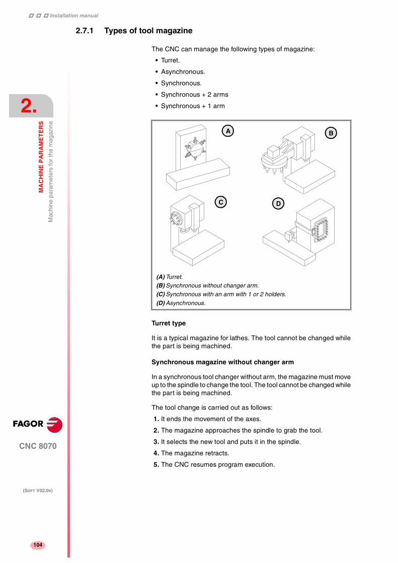
Installation manual
111
CNC 8070
2.
MA
CH
INE
PA
RA
ME
TE
RS
Mac
hine
par
amet
ers
for
the
mag
azin
e
(SOFT V02.0X)
104
2.7.1 Types of tool magazine
The CNC can manage the following types of magazine:
• Turret.
• Asynchronous.
• Synchronous.
• Synchronous + 2 arms
• Synchronous + 1 arm
Turret type
It is a typical magazine for lathes. The tool cannot be changed whilethe part is being machined.
Synchronous magazine without changer arm
In a synchronous tool changer without arm, the magazine must moveup to the spindle to change the tool. The tool cannot be changed whilethe part is being machined.
The tool change is carried out as follows:
1. It ends the movement of the axes.
2. The magazine approaches the spindle to grab the tool.
3. It selects the new tool and puts it in the spindle.
4. The magazine retracts.
5. The CNC resumes program execution.
(A) Turret.
(B) Synchronous without changer arm.
(C) Synchronous with an arm with 1 or 2 holders.
(D) Asynchronous.
A
C D
B

Installation manual
CNC 8070
MA
CH
INE
PA
RA
ME
TE
RS
Mac
hine
par
amet
ers
for
the
mag
azin
e
2.
(SOFT V02.0X)
105
Asynchronous magazines with changer arm (1 or 2 holders).
Synchronous magazines with tool changer arm (1 or 2 holders) havethe magazine close to the spindle. The tool cannot be changed whilemachining the part because the arm would collide.
The tool change is carried out as follows: Example with 2 holders:
1. The new tool is selected in the magazine.
2. It ends the movement of the axes.
3. The arm takes a tool on each holder (from the magazine and fromthe spindle) and swaps them.
4. The arm retracts
5. The CNC resumes program execution.
Asynchronous magazines
An asynchronous magazine is located away from the spindle. Most ofthe movements may be carried out while machining the part, thusminimizing machining time.
The tool change is carried out as follows:
1. While machining, a new tool is selected at the magazine, thechanger arm picks it up and brings it closer to the spindle.
2. It ends the movement of the axes.
3. The other holder picks up the tool that is in the spindle and makesthe change.
4. The program resumes execution and the changer arm returns tothe magazine to leave the tool.

Installation manual
111
CNC 8070
2.
MA
CH
INE
PA
RA
ME
TE
RS
Mac
hine
par
amet
ers
for
HM
I (In
terf
ace)
(SOFT V02.0X)
106
2.8 Machine parameters for HMI (Interface)
These parameters are used to define the communication environment(interface) between the operator and the CNC.
To validate the changes made to these parameters, the CNC must bereset.
Customizing
WINDOW Dimensions of the main window
The following parameters must be set: POSX, POSY, WIDTH andHEIGHT.
POSX X coordinate of the top left cornerPOSY Y coordinate of the top left cornerWIDTH Width of the windowHEIGHT Height of the window
They are defined in pixels. They are only used for the PC simulatorversion. They should not be changed at the CNC.
VMENU Position of the vertical softkey-menu
Depending on hardware, the vertical softkeys F8 through F12 appearon the left or on the right of the monitor.
LANGUAGE Work language
Select a language among those available.
ENGLISH SPANISH ITALIAN
GERMAN FRENCH BASQUE
PORTUGUESE
USERKEY Customizing the user key
To associate a function with the user key.
The FUNCTION parameter must be set. Depending on the optionselected, either parameter COMPONENT or APPLICATION will have tobe set.
Possible values: Left / Right.
By default: Right.
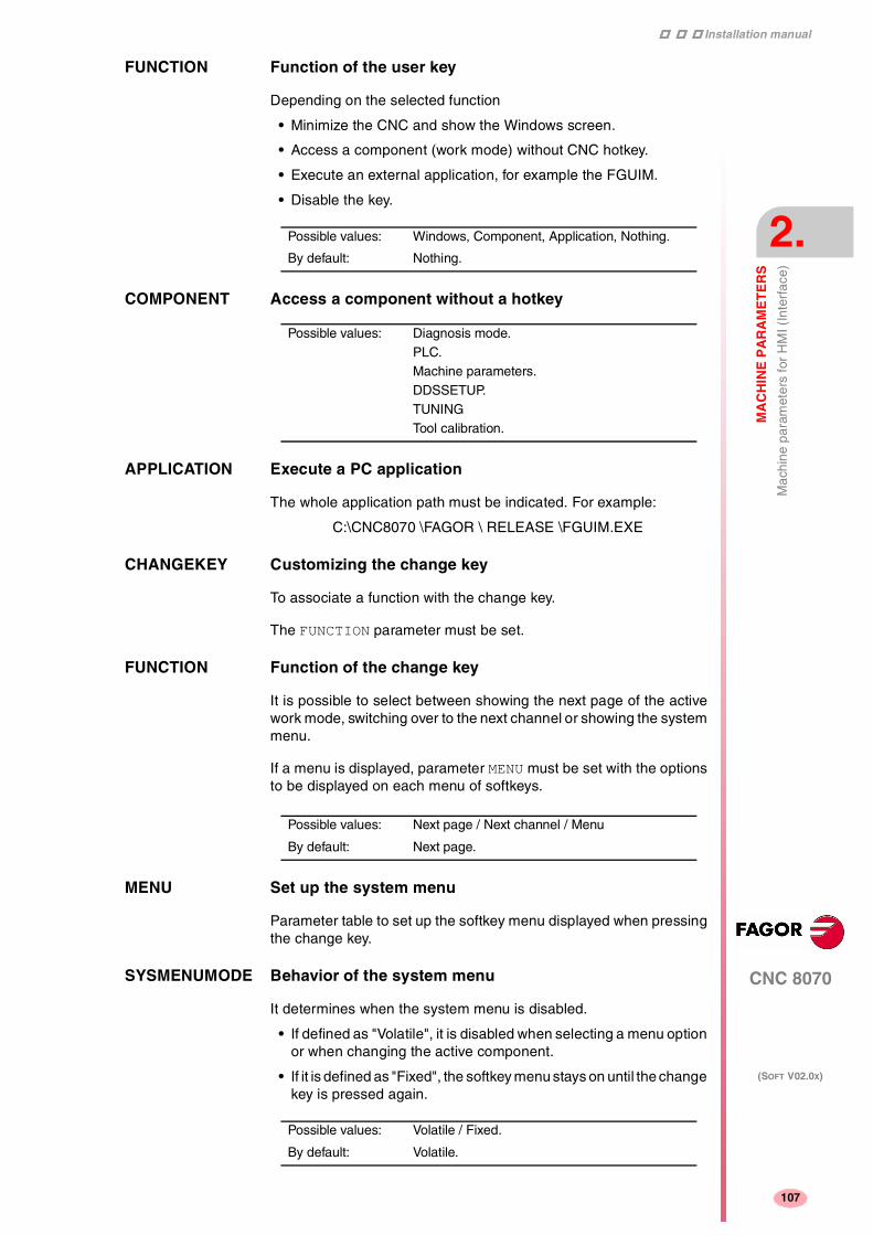
Installation manual
CNC 8070
MA
CH
INE
PA
RA
ME
TE
RS
Mac
hine
par
amet
ers
for
HM
I (In
terf
ace)
2.
(SOFT V02.0X)
107
FUNCTION Function of the user key
Depending on the selected function
• Minimize the CNC and show the Windows screen.
• Access a component (work mode) without CNC hotkey.
• Execute an external application, for example the FGUIM.
• Disable the key.
COMPONENT Access a component without a hotkey
APPLICATION Execute a PC application
The whole application path must be indicated. For example:
C:\CNC8070 \FAGOR \ RELEASE \FGUIM.EXE
CHANGEKEY Customizing the change key
To associate a function with the change key.
The FUNCTION parameter must be set.
FUNCTION Function of the change key
It is possible to select between showing the next page of the activework mode, switching over to the next channel or showing the systemmenu.
If a menu is displayed, parameter MENU must be set with the optionsto be displayed on each menu of softkeys.
MENU Set up the system menu
Parameter table to set up the softkey menu displayed when pressingthe change key.
SYSMENUMODE Behavior of the system menu
It determines when the system menu is disabled.
• If defined as "Volatile", it is disabled when selecting a menu optionor when changing the active component.
• If it is defined as "Fixed", the softkey menu stays on until the changekey is pressed again.
Possible values: Windows, Component, Application, Nothing.
By default: Nothing.
Possible values: Diagnosis mode.PLC.Machine parameters.DDSSETUP.TUNINGTool calibration.
Possible values: Next page / Next channel / Menu
By default: Next page.
Possible values: Volatile / Fixed.
By default: Volatile.

Installation manual
111
CNC 8070
2.
MA
CH
INE
PA
RA
ME
TE
RS
Mac
hine
par
amet
ers
for
HM
I (In
terf
ace)
(SOFT V02.0X)
108
SYSHMENU Horizontal system-menuSYSVMENU Vertical system-menu
It sets the options that will appear on each softkey-menu.
• The menu will be disabled.
• The menu shows the various pages or screens of the active workmode.
• The menu shows the available channels.
• The menu shows the components or work modes of the CNC.
ESCAPEKEY Customizing the escape key
To associate a function with the escape key.
The FUNCTION parameter must be set. Depending on the optionselected, parameter NPREVIOUS must be set.
FUNCTION Function associated with the escape key
It is possible to choose between showing the previous softkey-menu,the previous work mode or both. If "both" is selected, every time thiskey is pressed, it will show the previous softkey menu until reachingthe main menu. From then on, the work mode will change.
NPREVIOUS Maximum number of previous components stored.
SIMJOGPANEL Simulated JOG panel
A simulated JOG panel is a window that lays over the CNC screen.It is used to simulate the JOG keys and the work modes accessingkeys.
It may have to be used when working with Telediagnosis (remotecontrol of the CNC).
This parameter indicates whether the simulated panel is available ornot.
To select or deselect it, press [CTRL] + [J].
Possible values: Disabled.Screens.Channels.
Components.
By default: Disabled.
Possible values: Pr. menuPr component.Pr. Menu/Cmpnt
By default: Pr. menu
Possible values: 1 to 5.
By default: 1.
Possible values: Yes / No.
By default: No.

Installation manual
CNC 8070
MA
CH
INE
PA
RA
ME
TE
RS
Mac
hine
par
amet
ers
for
HM
I (In
terf
ace)
2.
(SOFT V02.0X)
109
WINEXIT Exit Windows when closing the CNC
It indicates whether Windows is closed or not when exiting the CNCusing [ALT] + [F4].
DIAGPSW (Reserved)
Possible values: Yes / No.
By default: No (Windows is not closed).

Installation manual
111
CNC 8070
2.
MA
CH
INE
PA
RA
ME
TE
RS
OE
M m
achi
ne p
aram
eter
s
(SOFT V02.0X)
110
2.9 OEM machine parameters
Reading drive variables
DRIVEVAR Drive variables table
Configures the access to the drive variables from the CNC
It offers parameters SIZE and DATAto define it.
SIZE Number of variables to consulted at the drive
DATA List of drive variables
The following parameters must be set for each variable.
MNEMONIC AXIS ID
TYPE MODE
MNEMONIC Name of the variable at the drive
Mnemonic to be used for the variable at the CNC. The access to thevariable from the CNC will be as follows:
(V.)DRV.{mnemonic}.{axis}
(V.)DRV.{mnemonic}.{spindle}
AXIS Axis or spindle that the variable belongs to
The variable may be associated with a particular axis or spindle or maybe good for all of them. When defined with the "*" character, it meansall the axes and spindles.
ID Variable identifier at the drive
Sercos ID identifier that identifies the variable at the drive.
TYPE Access type
The access to the variable may be synchronous or asynchronous.
Variables of synchronous access are managed through the cyclicchannel. Variables of asynchronous access are managed through theservice channel, even if the default option at the drive is the opposite.
Not all the variables may be defined with synchronous access; onlythe ones allowed by the drive. Refer to the drive manual.
Possible values: from 0 to 99.
By default: 0
Possible values: Axes and spindles defined in AXISNAME.The "*" character means all the axes spindles.

Installation manual
CNC 8070
MA
CH
INE
PA
RA
ME
TE
RS
OE
M m
achi
ne p
aram
eter
s
2.
(SOFT V02.0X)
111
MODE Access mode
The access to the variable may be read-only or read-write.
Generic OEM-parameters
MTBPAR OEM-parameter table
They are generic parameters that the OEM can use as machineparameters.
It offers parameters SIZE and DATAto define it.
SIZE Number of OEM parameters
DATA OEM parameters
The access to these parameters using variables will be as follows.
(V.)MTB.P[n]
Cam editor
CAMTABLE Table of electronic cams
It offers parameters SIZE and DATAto define it.
SIZE Number of electronic cams
DATA Cam data
It shows the available cams.
CAM1..16 Electronic-cam editor
Cam editor with friendly assistance to analyze the behavior of the camprojected through graphically assisted data entry for speed,acceleration and jerk.
Possible values: from 0 to 1000.
By default: 0
Possible values: from 0 to 16.
By default: 0
This function has a specific manual.
Refer to the specific documentation to obtain further informationregarding the requirements and operation of the electronic cam.

Installation manual
116
CNC 8070
2.
MA
CH
INE
PA
RA
ME
TE
RS
Alp
habe
tical
list
ing
of m
achi
ne p
aram
eter
s
(SOFT V02.0X)
112
2.10 Alphabetical listing of machine parameters
ABSFEEDBACK Absolute feedback system . . . . . . . . . . . . . . . . . . (L R S) (A S X)......... Page 60ABSOFF Offset referred to the distance-coded I0 . . . . . . . (L R S) (A S X)......... Page 71ACCEL Acceleration . . . . . . . . . . . . . . . . . . . . . . . . . . . . . (L R S) (A S X)......... Page 68ACCJERK Acceleration Jerk . . . . . . . . . . . . . . . . . . . . . . . . . (L R S) (A S X)......... Page 68ACFGAIN Percentage of AC-Forward in automatic . . . . . . . (L R S) (A S X)......... Page 66ACFWFACTOR Acceleration time constant . . . . . . . . . . . . . . . . . . (L R S) (A Ss X)....... Page 65ACTBAKAN Application of the additional command pulse. . . . (L R S) (A S) ............ Page 62ALIGNC "C" axis alignment for diametrical machining .......................................... Page 29ANAOUTID Axis analog output . . . . . . . . . . . . . . . . . . . . . . . . (L R S) (A) ............... Page 77ANTIME Anticipation time...................................................................................... Page 30APPLICATION Execute a PC application ........................................................................ Page 107AUTOGEAR Automatic gear change . . . . . . . . . . . . . . . . . . . . (S) (A S X) ............... Page 44AXISCH Feedback sign change. . . . . . . . . . . . . . . . . . . . . (L R S) (A S X)......... Page 61AXISEXCH Channel changing permission . . . . . . . . . . . . . . . (L R S) (A S X)......... Page 40AXISMODE Operating mode of the rotary axis . . . . . . . . . . . . (R) (A S X) ............... Page 42AXISNAME Name of each axis .................................................................................. Page 13AXISTYPE Type of axis . . . . . . . . . . . . . . . . . . . . . . . . . . . . . (L R S) (A S X)......... Page 40BACKLASH Backlash . . . . . . . . . . . . . . . . . . . . . . . . . . . . . . . (L R S) (A S X)......... Page 61BAKANOUT Additional command pulse. . . . . . . . . . . . . . . . . . (L R S) (A S) ............ Page 62BAKTIME Duration of the additional command pulse. . . . . . (L R S) (A S) ............ Page 62BIDIR Bi-directional compensation. . . . . . . . . . . . . . . . . (L R S) (A S X)......... Page 54BIDIR Bi-directional compensation.................................................................... Page 22CANLENGTH CAN Bus cable length ............................................................................. Page 19CAXIS Works as a "C" axis . . . . . . . . . . . . . . . . . . . . . . . (R S) (A S X)............ Page 44CAXNAME Axis working as "C" axis (by default)....................................................... Page 29CAXSET Work set for "C" axis . . . . . . . . . . . . . . . . . . . . . . (R S) (A S X)............ Page 44CHANGEKEY Customizing the change key ................................................................... Page 107CHAXISNAME Name of the axes of the channel ............................................................ Page 28CHNAXIS Number of axes of the channel ............................................................... Page 28CHNSPDL Number of spindles of the channel ......................................................... Page 28CHSPDLNAME Name of each spindle of the channel...................................................... Page 28CHTYPE Type of channel ...................................................................................... Page 27CIRINERR Absolute radius error............................................................................... Page 35CIRINFACT Percentage radius error .......................................................................... Page 35COMPAXIS Axis suffering the effects of the movement (compensated) .................... Page 21COMPONENT Access a component without a hotkey.................................................... Page 107COUNTERID Feedback input for the handwheel .......................................................... Page 78COUNTERID Feedback input of the axis . . . . . . . . . . . . . . . . . . (L R S) (A) ............... Page 77CROSSCOMP Cross compensation tables..................................................................... Page 21CYCLIC Cyclic tool changer.................................................................................. Page 102DATA Leadscrew error compensation at each point . . . (L R S) (A S X)......... Page 54DATA M function table....................................................................................... Page 84DATA Table defining the compensation at each point ...................................... Page 22DATA1..DATA42 Definition of the C axis kinematics (Types 41 through 43)...................... Page 100DATA1..DATA42 Definition of the kinematics of the spindle - table (Types 13 through 16) Page 96DATA1..DATA42 Definition of the spindle kinmatics (Types 1 through 8) .......................... Page 89DATA1..DATA42 Definition of the table kinematics (Types 9 through 12) .......................... Page 93DECEL Deceleration. . . . . . . . . . . . . . . . . . . . . . . . . . . . . (L R S) (A S X)......... Page 68DECINPUT Availability of a home switch . . . . . . . . . . . . . . . . (L R S) (A S) ............ Page 48DECJERK Acceleration Jerk . . . . . . . . . . . . . . . . . . . . . . . . . (L R S) (A S X)......... Page 68DEFAULTSET Default work set . . . . . . . . . . . . . . . . . . . . . . . . . . (L R S) (A S X)......... Page 58DIAGPSW (Reserved) .............................................................................................. Page 109DIAMPROG Programming in diameters. . . . . . . . . . . . . . . . . . (L) (A S X)................ Page 48DIFFCOMP Gantry. Difference compensation after G74............................................ Page 17DIMOD 1..64 Base index of the digital input modules .................................................. Page 24DIMODADDR Table of digital input modules ................................................................. Page 24DISTLUBRI Distance for lubrication pulse. . . . . . . . . . . . . . . . (L R S) (A S X)......... Page 75DOMOD 1..64 Base index of the digital output modules ................................................ Page 25DOMODADDR Table of digital output modules ............................................................... Page 24DRIVEID Sercos drive address . . . . . . . . . . . . . . . . . . . . . . (L R S) (S) ............... Page 41

Installation manual
CNC 8070
MA
CH
INE
PA
RA
ME
TE
RS
Alp
habe
tical
list
ing
of m
achi
ne p
aram
eter
s
2.
(SOFT V02.0X)
113
DRIVETYPE Drive type . . . . . . . . . . . . . . . . . . . . . . . . . . . . . . . (L R S) (A S X)......... Page 40DTIME Estimated time for a D function............................................................... Page 23DWELL Dwell for dead axes. . . . . . . . . . . . . . . . . . . . . . . . (L R S) (A S X)......... Page 47ESCAPEKEY Customizing the escape key ................................................................... Page 108ESTDELAY Following error delay. . . . . . . . . . . . . . . . . . . . . . . (L R S) (A S) ............ Page 74EXTMULT External factor for distance-coded mark . . . . . . . . (L R S) (A X) ............ Page 71FACEAXIS Face axis (lathe) . . . . . . . . . . . . . . . . . . . . . . . . . . (L) (A S X)................ Page 42FBACKAL Feedback alarm activation . . . . . . . . . . . . . . . . . . (L R S) (A) ............... Page 60FBACKSRC Type of feedback. . . . . . . . . . . . . . . . . . . . . . . . . . (L R S) (S) ............... Page 41FEDYNAC % of following error deviation . . . . . . . . . . . . . . . . (L R S) (A S) ............ Page 74FEEDND Apply the programmed feedrate to all the axes of the channel............... Page 36FFGAIN Percentage of Feed-Forward in automatic . . . . . . (L R S) (A S X)......... Page 64FFWTYPE Pre-control type. . . . . . . . . . . . . . . . . . . . . . . . . . . (L R S) (A S X)......... Page 64FILTER Filter table . . . . . . . . . . . . . . . . . . . . . . . . . . . . . . . (L R S) (A S X)......... Page 55FLWEMONITOR Type of monitoring . . . . . . . . . . . . . . . . . . . . . . . . (L R S) (A S X)......... Page 73FREQUENCY Break or mid frequency. . . . . . . . . . . . . . . . . . . . . (L R S) (A S X)......... Page 57FUNCTION Function associated with the escape key................................................ Page 108FUNCTION Function of the change key..................................................................... Page 107FUNCTION Function of the user key.......................................................................... Page 107G00FEED Feedrate in G00 . . . . . . . . . . . . . . . . . . . . . . . . . . (L R S) (A S X)......... Page 63GANTRY Gantry axes............................................................................................. Page 16GROUND Ground tools are permitted (manual load) .............................................. Page 101GROUPID Group the channel belongs to................................................................. Page 27HEIGHT Height of the window............................................................................... Page 106HIDDENCH Hidden channel ....................................................................................... Page 27HIRTH Hirth axis . . . . . . . . . . . . . . . . . . . . . . . . . . . . . . . . (L R) (A S X) ............ Page 41HPITCH Hirth axis pitch. . . . . . . . . . . . . . . . . . . . . . . . . . . . (L R) (A S X) ............ Page 41HTIME Estimated time for an H function............................................................. Page 23I0CODDI1 Gap between two fixed distance-coded I0's . . . . . (L R S) (A S X)......... Page 72I0CODDI2 Gap between two variable distance-coded I0's. . . (L R S) (A S X)......... Page 72I0TYPE Type of reference mark (I0). . . . . . . . . . . . . . . . . . (L R S) (A S X)......... Page 69ICORNER Type of corner (G5/G7/G50) by default................................................... Page 34IFEED Type of feedrate (G94/G95) by default. .................................................. Page 33IMOVE Type of movement (G0/G1) by default.................................................... Page 33INCHES Default work units (mm, inch).................................................................. Page 20INCJOGDIST Incremental jog distances . . . . . . . . . . . . . . . . . . . (L R) (A S X) ............ Page 53INCJOGFEED Incremental jog feedrates . . . . . . . . . . . . . . . . . . . (L R) (A S X) ............ Page 53INPOMAX Time to get in position. . . . . . . . . . . . . . . . . . . . . . (L R S) (A S X)......... Page 75INPOSW In position zone. . . . . . . . . . . . . . . . . . . . . . . . . . . (L R S) (A S X)......... Page 61INPOTIME Minimum in position time. . . . . . . . . . . . . . . . . . . . (L R S) (A S X)......... Page 75INPUTREV Turns of motor shaft . . . . . . . . . . . . . . . . . . . . . . . (L R S) (A S X)......... Page 59INPUTREV2 Turns of motor shaft (2nd feedback) . . . . . . . . . . . (L R S) (S) ............... Page 60IPLANE Main plane (G17/G18) by default ............................................................ Page 32IPOACCP Maximum % of execution acceleration in G201 . . (L R) (A S X) ............ Page 51IPOFEEDP Maximum % of execution feedrate in G201 . . . . . (L R) (A S X) ............ Page 51IRCOMP Tool radius compensation mode (G136/G137) by default ...................... Page 33ISYSTEM Type of programming (G90/G91) by default. .......................................... Page 32JOGFEED Continuous JOG mode feedrate . . . . . . . . . . . . . . (L R) (A S X) ............ Page 50JOGKEYDEF Axis and moving direction ....................................................................... Page 79JOGRAPFEED Continuous rapid JOG mode feedrate . . . . . . . . . (L R) (A S X) ............ Page 51JOGTYPE JOG behavior.......................................................................................... Page 80KINEMATIC Kinematics table...................................................................................... Page 87KINID Default kinematics number...................................................................... Page 30LACC1 Acceleration of the first section . . . . . . . . . . . . . . . (L R S) (A S X)......... Page 67LACC2 Acceleration of the second section . . . . . . . . . . . . (L R S) (A S X)......... Page 67LANGUAGE Work language........................................................................................ Page 106LFEED Change speed. . . . . . . . . . . . . . . . . . . . . . . . . . . . (L R S) (A S X)......... Page 67LIMIT- Negative software limit . . . . . . . . . . . . . . . . . . . . . (L R) (A S X) ............ Page 46LIMIT+ Positive software limit . . . . . . . . . . . . . . . . . . . . . . (L R) (A S X) ............ Page 46LONGAXIS Longitudinal axis (lathe) . . . . . . . . . . . . . . . . . . . . (L) (A S X)................ Page 42LOOPCH Analog voltage sign change . . . . . . . . . . . . . . . . . (L R S) (A S X)......... Page 61LOOPTIME CNC cycle (loop) time ............................................................................. Page 18LOSPDLIM lower percentage for rpm OK . . . . . . . . . . . . . . . . (S) (A S X) ............... Page 45

Installation manual
116
CNC 8070
2.
MA
CH
INE
PA
RA
ME
TE
RS
Alp
habe
tical
list
ing
of m
achi
ne p
aram
eter
s
(SOFT V02.0X)
114
LSCRWCOMP Leadscrew error compensation . . . . . . . . . . . . . . (L R S) (A S X)......... Page 53LSCRWDATA Leadscrew compensation table . . . . . . . . . . . . . . (L R S) (A S X)......... Page 53M6ALONE Action when executing an M06 without selecting a T ............................. Page 103MAGAZINE Tool magazine table................................................................................ Page 101MANACCP Maximum % of jogging acceleration in G201. . . . (L R) (A S X) ............ Page 51MANACFGAIN Percentage of AC-Forward in JOG mode . . . . . . (L R S) (A X) ............ Page 66MANAGEMENT Management related parameters ............................................................ Page 102MANFEEDP Maximum % of jogging feedrate in G201. . . . . . . (L R) (A S X) ............ Page 51MANFFGAIN Percentage of Feed-Forward in manual. . . . . . . . (L R S) (A X) ............ Page 65MANNEGSW Maximum negative travel with G201 . . . . . . . . . . (L R) (A S X) ............ Page 50MANPG Table of handwheels ............................................................................... Page 78MANPOSSW Maximum positive travel with G201 . . . . . . . . . . . (L R) (A S X) ............ Page 50MANUAL Manual (jog) operating mode parameters . . . . . . (L R) (A S X) ............ Page 50MASTERAXIS Gantry. Master or main axis .................................................................... Page 17MAXCOMP Maximum arithmetic parameter common to all the channels.................. Page 21MAXCOUPE Gantry. Maximum difference allowed...................................................... Page 17MAXFLWE Maximum following error in motion . . . . . . . . . . . (L R S) (A S) ............ Page 74MAXGLBP Maximum global arithmetic parameter .................................................... Page 20MAXLOCP Maximum local arithmetic parameter ...................................................... Page 20MAXMANACC Maximum acceleration in JOG mode . . . . . . . . . . (L R) (A S X) ............ Page 51MAXMANFEED Continuous maximum JOG mode feedrate . . . . . (L R) (A S X) ............ Page 51MAXOVR Maximum axis override (%)..................................................................... Page 35MAXOVR Maximum spindle override . . . . . . . . . . . . . . . . . . (S) (A S X) ............... Page 46MAXROUND Maximum rounding error in G5 ............................................................... Page 34MAXVOLT Analog voltage to reach G00FEED . . . . . . . . . . . (L R S) (A Ss) .......... Page 63MINAENDW Minimum duration of the AUX END signal .............................................. Page 23MINANOUT Minimum analog output . . . . . . . . . . . . . . . . . . . . (L R S) (A) ............... Page 77MINCOMP Minimum arithmetic parameter common to all the channels................... Page 21MINFLWE Maximum following error when stopped. . . . . . . . (L R S) (A S) ............ Page 73MINGLBP Minimum global arithmetic parameter ..................................................... Page 20MINLOCP Minimum local arithmetic parameter ....................................................... Page 20MINOVR Minimum spindle override . . . . . . . . . . . . . . . . . . (S) (A S X) ............... Page 46MNUM M function number .................................................................................. Page 84MODCOMP Module compensation . . . . . . . . . . . . . . . . . . . . . (R S) (A Ss X).......... Page 44MODERR Module error. Increments . . . . . . . . . . . . . . . . . . . (R S) (A Ss X).......... Page 76MODLOWLIM Module's lower limit . . . . . . . . . . . . . . . . . . . . . . . (R S) (A Ss X).......... Page 75MODNROT Module error. Turns . . . . . . . . . . . . . . . . . . . . . . . (R S) (A Ss X).......... Page 76MODUPLIM Module's upper limit . . . . . . . . . . . . . . . . . . . . . . . (R S) (A Ss X).......... Page 75MOVAXIS Axis whose movement affects another axis (master).............................. Page 21MPGAXIS Axis associated with the handwheel ....................................................... Page 79MPGFILTER Filter time for the handwheel . . . . . . . . . . . . . . . . (L R) (A S X) ............ Page 53MPGRESOL Handwheel resolution . . . . . . . . . . . . . . . . . . . . . (L R) (A S X) ............ Page 52MPROGNAME Name of subroutine associated with M function...................................... Page 85MTABLESIZE Number of table elements....................................................................... Page 84MTIME Estimated time for an M function............................................................. Page 85NAXIS Number of axes governed by the CNC ................................................... Page 13NCHANNEL Number of channels ................................................................................ Page 13NDIMOD Total of digital input modules .................................................................. Page 24NDOMOD Total of digital output modules ................................................................ Page 24NEGERROR Error in the negative direction . . . . . . . . . . . . . . . (L R S) (A S X)......... Page 55NEGERROR Error in the negative direction ................................................................. Page 22NKIN Number of different kinematics ............................................................... Page 87NMPG Number of handwheels ........................................................................... Page 78NORBWIDTH Standard bandwidth . . . . . . . . . . . . . . . . . . . . . . . (L R S) (A S X)......... Page 57NPARSETS Number of parameter sets . . . . . . . . . . . . . . . . . . (L R S) (A S X)......... Page 58NPCROSS Number of points in the table .................................................................. Page 21NPOINTS Number of points of the table. . . . . . . . . . . . . . . . (L R S) (A S X)......... Page 54NPREVIOUS Maximum number of previous components stored. ................................ Page 108NPULSES Number of encoder pulses. . . . . . . . . . . . . . . . . . (L R S) (A Ss X)....... Page 60NPULSES2 Number of encoder (2nd feedback) pulses . . . . . (L R S) (A Ss X)....... Page 60NSPDL Number of spindles governed by the CNC.............................................. Page 17NTOOLMZ Number of tool magazines ...................................................................... Page 101OEMSUB (G18x) Subroutines associated with functions G180 through G189 ................... Page 38

Installation manual
CNC 8070
MA
CH
INE
PA
RA
ME
TE
RS
Alp
habe
tical
list
ing
of m
achi
ne p
aram
eter
s
2.
(SOFT V02.0X)
115
OPMODEP Sercos drive operation mode . . . . . . . . . . . . . . . . (L R S) (S) ............... Page 41OPTIMIZE Tool management. .................................................................................. Page 102ORDER Filter order. . . . . . . . . . . . . . . . . . . . . . . . . . . . . . . (L R S) (A S X)......... Page 56OUTPUTREV Turns of machine axis . . . . . . . . . . . . . . . . . . . . . . (L R S) (A S X)......... Page 59OUTPUTREV2 Turns of machine axis (2nd feedback) . . . . . . . . . (L R S) (S) ............... Page 60PITCH Leadscrew pitch . . . . . . . . . . . . . . . . . . . . . . . . . . (L R S) (A S X)......... Page 59PITCH2 Leadscrew pitch (2nd feedback) . . . . . . . . . . . . . . (L R S) (S) ............... Page 59PLCDATASIZE Size of the PLC's shared data area ........................................................ Page 26PLCOINC PLC offset increment per cycle . . . . . . . . . . . . . . . (L R S) (A S X)......... Page 47POLARM3 Sign of the analog voltage for M3 . . . . . . . . . . . . . (S) (A Ss X) ............. Page 77POLARM4 Sign of the analog voltage for M4 . . . . . . . . . . . . . (S) (A Ss X) ............. Page 77POSERROR Error in the positive direction. . . . . . . . . . . . . . . . . (L R S) (A S X)......... Page 55POSERROR Error in the positive direction................................................................... Page 22POSITION Position of each point . . . . . . . . . . . . . . . . . . . . . . (L R S) (A S X)......... Page 55POSITION Position of the master axis...................................................................... Page 22POSX X coordinate of the top left corner........................................................... Page 106POSY Y coordinate of the top left corner........................................................... Page 106PRB1MAX Maximum probe coordinate (abscissa axis)............................................ Page 38PRB1MIN Minimum probe coordinate (abscissa axis)............................................. Page 38PRB2MAX Maximum probe coordinate (ordinate axis)............................................. Page 38PRB2MIN Minimum probe coordinate (ordinate axis).............................................. Page 38PRB3MAX Maximum probe coordinate (axis perpendicular to the plane) ................ Page 38PRB3MIN Minimum probe coordinate (axis perpendicular to the plane) ................. Page 38PRBDI1 Digital input associated with probe 1....................................................... Page 25PRBDI2 Digital input associated with probe 2....................................................... Page 25PRBPULSE1 Type of pulse of probe 1 ......................................................................... Page 25PRBPULSE2 Type of pulse of probe 2 ......................................................................... Page 25PRELFITI Tandem. Filter time to apply the preload................................................. Page 15PRELOAD Tandem. Preload between both motors.................................................. Page 15PREPFREQ Number of blocks to prepare per cycle ................................................... Page 29PRGFREQ Frequency of the PRG module (in cycles) .............................................. Page 18PROBE A table-top probe is being used .............................................................. Page 25PROBEAXIS Probing axis . . . . . . . . . . . . . . . . . . . . . . . . . . . . . (L R) (A S X) ............ Page 48PROBEDATA Channel related probe parameters ......................................................... Page 38PROBEDATA Probe parameters ................................................................................... Page 25PROBEDELAY Delay for the probe 1 signal . . . . . . . . . . . . . . . . . (L R) (A S X) ............ Page 49PROBEDELAY2 Delay for the probe 2 signal . . . . . . . . . . . . . . . . . (L R) (A S X) ............ Page 49PROBEFEED Maximum probing feedrate . . . . . . . . . . . . . . . . . . (L R) (A S X) ............ Page 49PROBERANGE Maximum braking distance . . . . . . . . . . . . . . . . . . (L R) (A S X) ............ Page 48PROGAIN Proportional gain . . . . . . . . . . . . . . . . . . . . . . . . . (L R S) (A S X)......... Page 63RANDOM Random magazine.................................................................................. Page 101RAPIDOVR Override acts in G00 (from 0 to 100%) ................................................... Page 36REFDIREC Homing direction . . . . . . . . . . . . . . . . . . . . . . . . . . (L R S) (A S X)......... Page 48REFFEED1 Fast home searching feedrate . . . . . . . . . . . . . . . (L R S) (A S X)......... Page 70REFFEED2 Slow home searching feedrate . . . . . . . . . . . . . . . (L R S) (A S X)......... Page 70REFNEED Mandatory home search . . . . . . . . . . . . . . . . . . . . (L R S) (A S X)......... Page 54REFNEED Mandatory home search ......................................................................... Page 22REFPSUB (G74) Subroutine associated with function G74................................................ Page 37REFPULSE Type of I0 pulse. . . . . . . . . . . . . . . . . . . . . . . . . . . (L R S) (A S X)......... Page 70REFSHIFT Offset of the reference point . . . . . . . . . . . . . . . . . (L R S) (A S X)......... Page 70REFTIME Estimated home searching time.............................................................. Page 23REFVALUE Position of the reference point . . . . . . . . . . . . . . . (L R S) (A S X)......... Page 70REPOSFEED Maximum repositioning feedrate. . . . . . . . . . . . . . (L R) (A S X) ............ Page 49ROPARMAX Maximum global read-only arithmetic parameter.................................... Page 20ROPARMIN Minimum global read-only arithmetic parameter ..................................... Page 20ROUNDFEED Percentage of feedrate in G5.................................................................. Page 34ROUNDTYPE Rounding type in G5 (by default) ............................................................ Page 34SERBRATE Sercos transmission rate......................................................................... Page 19SERCOSDATA SERCOS drive data . . . . . . . . . . . . . . . . . . . . . . . (L R S) (S) ............... Page 40SERPOWSE Sercos optical power............................................................................... Page 19SERVOOFF Offset compensation . . . . . . . . . . . . . . . . . . . . . . . (L R S) (A) ............... Page 77SHARE % of signal going through the filter . . . . . . . . . . . . (L R S) (A S X)......... Page 57SHORTESTWAY Via shortest way . . . . . . . . . . . . . . . . . . . . . . . . . . (R) (A S X) ............... Page 43

Installation manual
116
CNC 8070
2.
MA
CH
INE
PA
RA
ME
TE
RS
Alp
habe
tical
list
ing
of m
achi
ne p
aram
eter
s
(SOFT V02.0X)
116
SIMJOGPANEL Simulated JOG panel .............................................................................. Page 108SINMAGNI Sinusoidal multiplying factor. . . . . . . . . . . . . . . . . (L R S) (A X) ............ Page 60SIZE Size of the magazine (number of pockets).............................................. Page 101SLAVEAXIS Gantry. Slave axis ................................................................................... Page 17SLOPETYPE Default acceleration type ........................................................................ Page 31SPDLNAME Spindle name .......................................................................................... Page 18SPDLSTOP M2, M30 and Reset stop the spindle . . . . . . . . . . (S) (A S X) ............... Page 45SPDLTIME Estimated time for an S function . . . . . . . . . . . . . (S) (A S X) ............... Page 45SREVM05 G84. Reversal stops the spindle . . . . . . . . . . . . . (S) (A S X) ............... Page 45STEPOVR Spindle Override step . . . . . . . . . . . . . . . . . . . . . (S) (A S X) ............... Page 46STORAGE Parameters related to storage ................................................................ Page 101SUBPATH Path of program subroutines................................................................... Page 38SUBTABLE OEM-subroutines table ........................................................................... Page 37SWLIMITTOL Software limits tolerance . . . . . . . . . . . . . . . . . . . (L R) (A S X) ............ Page 46SYNCHTYPE Type of synchronization .......................................................................... Page 84SYSHMENU Horizontal system-menu ......................................................................... Page 108SYSMENUMODE Behavior of the system menu ................................................................. Page 107SYSVMENU Vertical system-menu.............................................................................. Page 108SZERO Speed considered "0 rpm" . . . . . . . . . . . . . . . . . . (S) (A X)................... Page 76TANDEM Tandem axis ........................................................................................... Page 14TCOMPLIM Tandem. Compensation limit .................................................................. Page 16TENDENCY Activation of tendency test . . . . . . . . . . . . . . . . . . (L R S) (A S) ............ Page 46TINTTIME Tandem. Integral gain (Kp) for the tandem axis...................................... Page 16TMASTERAXIS Tandem. Master or main axis.................................................................. Page 14TOOLSUB Name of the subroutine associated with T.............................................. Page 37TORQDIST Tandem. Torque distribution ................................................................... Page 14TPROGAIN Tandem. Proportional gain (Kp) for the tandem axis .............................. Page 15TSLAVEAXIS Tandem. Slave axis ................................................................................ Page 14TTIME Estimated time for a T function ............................................................... Page 23TYPCROSS Type of compensation............................................................................. Page 21TYPE Kinematics type....................................................................................... Page 87TYPE Magazine type......................................................................................... Page 102TYPE Type of filter . . . . . . . . . . . . . . . . . . . . . . . . . . . . . (L R S) (A S X)......... Page 56TYPLSCRW Type of compensation . . . . . . . . . . . . . . . . . . . . . (L R S) (A S X)......... Page 54UNIDIR Unidirectional rotation . . . . . . . . . . . . . . . . . . . . . (R) (A S X) ............... Page 43UPSPDLIM Upper percentage for rpm OK . . . . . . . . . . . . . . . (S) (A S X) ............... Page 45USERKEY Customizing the user key........................................................................ Page 106VMENU Position of the vertical softkey-menu ...................................................... Page 106WARNCOUPE Gantry. Maximum difference allowed to issue a warning........................ Page 17WIDTH Width of the window................................................................................ Page 106WINDOW Dimensions of the main window.............................................................. Page 106WINEXIT Exit Windows when closing the CNC...................................................... Page 109

3
117
CNC 8070
(SOFT V02.0X)
CONCEPTS
3.1 Tandem axis
A tandem axis consists of two electric motors mechanically coupledto each other forming a single transmission system (axis). It isnormally used to move the axes on large machines.
The following aspects may be pointed out in this configuration:
• A tandem axis helps provide the necessary torque to move an axiswhen a single motor is not capable of supplying enough torque todo it.
• Applying a pre-load torque between the main motor and the slavemotor reduces the backlash on the rack and pinion.
• The rigidity of the rack-and-pinion system is greater than that oflong leadscrews.
One of the many applications of controlling a tandem axis has to dowith gantry machines.
(A) Main or master motor. Besides generating torque, it is in charge ofpositioning.
(B) Slave motor. It only supplies torque.
Example of a Tandem axis made up of a rack-and-pinion systemdriven by two motors.

Installation manual
130
CNC 8070
3.
CO
NC
EP
TS
Tan
dem
axi
s
(SOFT V02.0X)
118
Example diagram of a gantry machine with two tandem axes.

Installation manual
CNC 8070
CO
NC
EP
TS
Tan
dem
axi
s
3.
(SOFT V02.0X)
119
3.1.1 Tandem axis configuration. Machine parameters
TANDEM Tandem axes
There may be up to 8 pairs of Tandem axes. Every pair must meet thefollowing requirements.
• Each master tandem axis admits one single slave tandem axis.
• The axes must be sercos in velocity.
• A preload may be applied between the two motors.
• Each motor may have a different rated torque.
• The turning direction of each motor may be different from theother's.
• The torque distribution between moth motors may be different from1:1 ratio. For example, on motors whose rated torque is different.
Each pair has the following machine parameters:
TMASTERAXIS TSLAVEAXIS TORQDIST
PRELOAD PRELFITI TPROGAIN
TINTIME TCOMPLIM
TMASTERAXIS Tandem. Master or main axis
TSLAVEAXIS Tandem. Slave axis
The name of the axes is defined by 1 or 2 characters. The firstcharacter must be one of the letters X - Y - Z - U - V - W - A - B - C.The second character is optional and will be a numerical suffixbetween 1 and 9. This way, the name of the axes may be any in the"X, X1...X9,...C, C1...C9" range.
TORQDIST Torque distribution
It sets the torque supplied by each motor to obtain the total necessarytorque on the tandem axis.
This parameter refers to the master axis. It is defined as thepercentage of the total torque required from the master axis. Thedifference between the value of this parameter and 100% is thepercentage applied to the slave axis.
If the motors are identical and they're both supposed to output thesame torque, this parameter should be set to 50%.
For example:
There are two motors, the master with 100 Nm and the slave with20 Nm and they will be working at the same percentage of load.
TORQDIST = 20/100 = 20%
Possible values: Any axis defined in the parameter "AXISNAME".
Possible values: From 0 to 100% (both included).
By default: 50%

Installation manual
130
CNC 8070
3.
CO
NC
EP
TS
Tan
dem
axi
s
(SOFT V02.0X)
120
PRELOAD Preload between both motors
It is the torque difference to be applied between the master axis andthe slave axis. This sets a traction between them in order to eliminatethe rack-and-pinion backlash when it is in rest position.
This parameter refers to the master axis. It is defined as thepercentage of the rated torque to be applied as preload.
In order for the two axes to supply opposite torques, the preload valuemust be greater than the maximum torque needed at all times,including accelerations.
This parameter may be modified from the oscilloscope and from thePLC.
PRELFITI Filter time to apply the preload
It eliminates the torque steps at the input of the tandem compensatorwhen setting a preload value. This avoids a step in the velocitycommands of the master and slave axes of the tandem.
Setting it to zero disables the filter.
This parameter may be modified from the oscilloscope.
TPROGAIN Proportional gain (Kp) for the tandem axis
The proportional controller generates an output proportional to thetorque error between the two motors.
This parameter may be modified from the oscilloscope.
Example: A tandem axis has a maximum speed of 2000 rpm and arated torque of 20 Nm. TPROGAIN has been set to 10%.
Kp = (2000 rpm / 20 Nm) · 0.1= 10 rpm/Nm.
Possible values: from -100% to 100%.
By default: 0 (it disables the preload).
Applying the preload necessarily implies mechanically joining themaster and slave axes that make up the tandem axis. Otherwise, themotors will move even without the control velocity command.
Possible values: from 0 to 65535 milliseconds.
By default: 1000ms
Possible values: from 0 to 100%.
By default: 0 (no proportional gain is applied).
kPSmaxTnom------------ TPROGAIN×=
Terror Tmaster– Tslave Preload+ +( )=
Speed kP Terror•=

Installation manual
CNC 8070
CO
NC
EP
TS
Tan
dem
axi
s
3.
(SOFT V02.0X)
121
TINTTIME Integral gain (Kp) for the tandem axis
The integral controller generates an output proportional to the integralof the torque error between the two motors.
This parameter may be modified from the oscilloscope.
TCOMPLIM Compensation limit
This parameter limits the maximum compensation applied by thetandem axis. This limit is also applied to the integral.
This parameter refers to the master axis. It is defined as percentageof the maximum speed of the master motor. If programmed with a "0"value, the output of the tandem control will be zero, thus disabling thetandem.
This parameter may be modified from the oscilloscope.
Possible values: from 0 to 65535 milliseconds.
By default: 0 (no integral gain is applied).
kiControlTimeIntegralTime----------------------------------- kp×=
Terror Tmaster– Tslave Preload+ +( )=
Speed ki Terror∑⋅=
Possible values: from 0 to 100%.
By default: 0

Installation manual
130
CNC 8070
3.
CO
NC
EP
TS
Tan
dem
axi
s
(SOFT V02.0X)
122
3.1.2 Effect of the preload
The following diagrams show the effect of preload in differentsituations.
Preload at rest
Preload with acceleration
Preload at constant speed. Friction torque > Preload
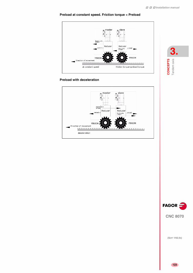
Installation manual
CNC 8070
CO
NC
EP
TS
Tan
dem
axi
s
3.
(SOFT V02.0X)
123
Preload at constant speed. Friction torque < Preload
Preload with deceleration

Installation manual
130
CNC 8070
3.
CO
NC
EP
TS
Tan
dem
axi
s
(SOFT V02.0X)
124
3.1.3 Tandem axis configuration. Block diagram
The block diagram of the tandem control system shows the mastertandem axis with its slave tandem axis. The block diagram for a gantrymachine consists of two identical diagrams to the one shown in thefigure.
The block diagram has an area for the drive and another one for theCNC that comprises the position loop and the control of the tandem.
Position and velocity loop
The position loop is closed only with the position of the master axisof the tandem. The velocity command of the master tandem axis isalso sent to the slave tandem axis closing the velocity loop.
The tandem control changes the velocity command of the master axisand that of the slave axis according to the torque distribution and theselected preload.
The feed-forward and AC-forward values of the master axis areapplied to the slave axis; consequently, they must have the same gearratios.

Installation manual
CNC 8070
CO
NC
EP
TS
Tan
dem
axi
s
3.
(SOFT V02.0X)
125
Tandem axis control.
The block diagram showing the application of the tandem axis controlis the following.
The meaning of the nomenclature being used is:
Torque of the master motor of the tandem
It is the percentage of the rated torque shown by the sercos variableTV2 of the drive that governs the master axis of the tandem. It is readthrough the sercos fast channel in each loop.
Torque of the slave motor of the tandem
It is the percentage of the rated torque shown by the sercos variableTV2 of the drive that governs the slave axis of the tandem. It is readthrough the sercos fast channel in each loop.
Torque distribution
Normalizing gain of the torque generated by the motors in order todistribute the torque in a ratio other than 1:1.
Preload
Previous torque applied to both tandem axes in opposite direction.This sets a traction between them in order to eliminate the rack-and-pinion backlash when it is in rest position. It is determined as the torquedifference supplied by each axis.
Applying the preload necessarily implies mechanically joining themaster and slave axes that make up the tandem axis. Otherwise, themotors will move even without the control velocity command.

Installation manual
130
CNC 8070
3.
CO
NC
EP
TS
Tan
dem
axi
s
(SOFT V02.0X)
126
Preload filter
First-order filter to prevent torque steps from coming in whenconfiguring the preload.
PI of the tandem
PI for making each motor provide its corresponding torque. Itincreases its velocity command if the torque being supplied is too lowand it decreases it if the torque being supplied is too high.
When defining a tandem axis, at each loop, the CNC reads via Sercosthe torque supplied by the master and the slave axes. This may resultin a smaller number of read and write variables available in the Sercosfast channel.

Installation manual
CNC 8070
CO
NC
EP
TS
Tan
dem
axi
s
3.
(SOFT V02.0X)
127
3.1.4 Tandem related variables
Related to general machine parameters
These variables are read-only synchronous and are evaluated duringblock preparation.
They have generic names. Replace the letter "i" with numbers,keeping the brackets.
Tandem related
These variables are read/write (R/W) synchronous and are evaluatedduring execution. They correspond to linear and rotary axes and to thespindle.
The mnemonics of the variables have generic names.
• Replace "Xn" with the name or logic number of the axis.
• Replace the "n" character with the channel number, maintainingthe brackets.
(V.)A.TPIOUT.[Xn] (V.)A.TPIIN.[Xn]
Both variables return the values in rpm. The axis must be a validtandem master, otherwise, it returns a value of zero.
(V.)A.TORQUE
The PLC reading of this variable comes in tenths (x10).
PRG PLC INT(V.)MPG.TMASTERAXIS[i] Tandem [i]. Logic number of the master axis R R R(V.)MPG.TSLAVEAXIS[i] Tandem [i]. Logic number of the slave axis R R R(V.)MPG.TORQDIST[i] Tandem [i]. Torque distribution R R R(V.)MPG.PRELOAD[i] Tandem [i]. Preload R R R(V.)MPG.PRELFITI[i] Tandem [i]. Time to apply the preload R R R(V.)MPG.TPROGAIN[i] Tandem [i]. Proportional gain R R R(V.)MPG.TINTIME[i] Tandem [i]. Integral gain R R R(V.)MPG.TCOMPLIM[i] Tandem [i]. Compensation Limit R R R
PRG PLC INT(V.)[n].A.TPIIN.Xn Input of the PI of the master axis of the tandem (in rpm) R R R(V.)[n].A.TPIOUT.Xn Output of the PI of the master axis of the tandem (in rpm) R R R(V.)[n].A.TFILTOUT.Xn Output of the pre-load filter R R R(V.)[n].A.PRELOAD.Xn Preload R/W R/W R/W(V.)[n].A.FTEO.Xn Velocity command for Sercos R R R(V.)[n].A.TORQUE.Xn Current torque in Sercos R R R

Installation manual
130
CNC 8070
3.
CO
NC
EP
TS
Tan
dem
axi
s
(SOFT V02.0X)
128
3.1.5 Tandem adjustment procedure
This procedure must bear in mind the type of machine. In general, theresonance frequency of a tandem machine is low; therefore, the CNCmust generate position commands without frequency componentshigher than the resonance frequency.
The process should be initiated with low jerk values (lower than 10m/sg3) and low Kv. They can always be increased in a laterreadjustment.
Steps for the adjustment
1. Move both axes independently.
The first step is to ensure the perfect operation of both the masterand the slave axes separately. Also verify that both axes move inthe same direction with similar dynamics.
2. Move one of the axes at a slow and constant speed.
2.1. Do not make jerky movements because the second motoris being dragged by the first one. In this situation, anyacceleration or deceleration forces it to go from one side ofthe backlash to the other thus making it jerky.
2.2. Verify that the turning direction of both motors are coherentonce the movement has been carried out.
2.3. Verify that the gear ratio in both motors is the same (samefeed for same turning speed).
2.4. Carry out a basic adjustment of the velocity loop so themachine can move. It will be readjusted later with bothmotors together.
2.5. Do not set the friction parameters (there is already enoughtorque to move the machine).
3. Repeat the procedure with the second axis.
When adjusting the loops, use the same parameters if the motorsare identical and the torque distribution is 50%. If the motors aredifferent, the axes must be adjusted so their dynamic response isthe same or very similar. When using AC-forward ("ACFGAIN" =YES), remember that each motor has half the inertia for a 50%torque distribution.
Observe that reversing the turning direction of a motor reverses thedirection of the torque and, consequently, it will be necessary tochange the direction of its values monitored with drive parametersSP43 and TP85.
i
Installation manual
CNC 8070
CO
NC
EP
TS
Tan
dem
axi
s
3.
(SOFT V02.0X)
129
4. Enable the tandem with both motors.
4.1. Disable the PI of the tandem.
4.2. Apply power and verify that the system is at rest.
4.3. Enter a low proportional value and eliminate the integralvalue of the PI of the tandem.
4.4. Without preload, verify that the machine moves and thateach motor supplies its corresponding torque according tothe parameter "TORQDIST" (e.g. half the torque for 50%distribution).
4.5. Monitor the torque of each motor (Sercos variable TV2).While stopped, increase the preload gradually until themotors supply torque in opposite directions.
4.6. Move slowly in both directions and verify that it worksproperly. Make sure that it is not jerky and that each motorsupplies its corresponding torque according to parameters"TORQDIST" and "PRELOAD".
4.7. Readjust the velocity loop in both motors with the methodused normally.
While changing the parameters of the velocity loop, the best thingwould be to change them on both drives at the same time. But, sincethis is not possible, it is recommended to make small changes in thevalues or make them while the motor is stopped.
i

Installation manual
130
CNC 8070
3.
CO
NC
EP
TS
Tan
dem
axi
s
(SOFT V02.0X)
130

4
131
CNC 8070
(SOFT V02.0X)
INTRODUCTION TO THE PLC
The PLC program (*.plc or *.c) may be either edited at the front panelor copied from a peripheral or PC.
It has a modular structure and may combine files in "C" language withfiles in mnemonic language.
Before executing it, its executable file must be generated.
On power-up, the CNC executes the executable PLC program storedin memory. If there is no such file, it will display the corresponding errormessage.
Data exchange takes place in automatic mode between the CNC andthe PLC.
The following is possible from the PLC:
• Control physical inputs and outputs (remote modules).
• Consult and/or modify CNC-PLC exchange variables.
• Consult and/or modify the internal CNC variables.
• Display messages or errors at the CNC.
The following is possible from the CNC:
• Transfer auxiliary functions M, H and S.
• Access PLC resources from any part-program.
Abbreviations used in this chapter
(=0) Low logic level
(=1) High logic level
(g.m.p.) General machine parameter

Installation manual
154
CNC 8070
4.
INT
RO
DU
CTI
ON
TO
TH
E P
LC
PLC
pro
gram
(SOFT V02.0X)
132
4.1 PLC program
The PLC program may combine a file in mnemonic language(extension: "plc") and another one in "C" language (extension: "c").
Both files must be located in the following directory:
C:\CNC8070 \MTB \PLC \PROJECT
It is recommended to use the mnemonic language file as the main PLCprogram, and the "C" language file for the auxiliary tasks (for example,temperature compensation).
Subroutines in the PLC program
The subroutines of the program in mnemonic language must bedefined outside of the modules, for example at the end of the programafter the END instruction.
The subroutines of the "C" language file must be defined as externalat the beginning of the mnemonic language program (extension:"plc"). The name of the subroutine must be written in capital letters inboth files.
"C" language programming offers a math library (trigonometric,logarithmic, etc.) that allows performing operations with tables, arrays,float type variables, etc.
PLC program with mnemonic language file.
Mnemonic.plc
PRG
()= MOV 1234 R201 = MOV 2345 R202
()= CAL SUMA
···
END
SUB SUMA
()= ADS R201 R202 R203
END
PLC program with a mnemonic language file and a "C" language file.
Mnemonic.plc
EXTERN SUMA
PRG
()= MOV 1234 R201 = MOV 2345 R202
()= CAL SUMA
···
END
Languagec.c
#include "plclib.h"
void SUMA (void)
(
R203=R201+R202
)

Installation manual
CNC 8070
INT
RO
DU
CTI
ON
TO
TH
E P
LC
Mod
ular
str
uctu
re o
f the
PLC
pro
gram
4.
(SOFT V02.0X)
133
4.2 Modular structure of the PLC program
It may comprise the following modules:
• Main module (PRG).
• Periodic module (PE)
• First Cycle module (CY1).
Every module must begin with its defining instruction (PRG, PE, CY1)and end with the END instruction.
PRG Main module
It is executed cyclically and it is in charge of analyzing and modifyingthe CNC inputs, outputs and variables.
CY1 First Cycle module
It is optional. It will only be executed when starting the PLC up. It isused to initialized the various resources and variables beforeexecuting the main program.
PEt Periodic execution module
It is optional. It is executed every t milliseconds. The value of "t" isindicated by the instruction: PEt (between 1 and 2147483647 ms).
It could be used to execute tasks that do not need to be executed atevery PLC cycle. For example, a task to be performed every 30seconds could be defined in a periodic module using the instructionPE 30000.
PE 1000
···
END
Defines the Periodic Module that will be executed every second(1000 ms).

Installation manual
154
CNC 8070
4.
INT
RO
DU
CTI
ON
TO
TH
E P
LC
Mod
ular
str
uctu
re o
f the
PLC
pro
gram
(SOFT V02.0X)
134
4.2.1 PLC module execution
CY1 First Cycle module
The First Cycle module (CY1) is only executed once when starting upthe PLC program.
PRG Main module
The Main module (PRG) will be executed continuously as often asindicated by the (g.m.p.) PRGFREQ which sets after how many CNCcycles is the Main module executed.
For example, with sampling period of 4 ms and PRGFREQ=2, the PRGmodule will be executed every 4x2=8 ms.
The PRG execution takes about 100 µs.
PEt Periodic execution module
The Periodic Module is executed with the frequency indicated by theinstruction PE t.
The periodic module PE 1000 will be executed every second (1000ms)

Installation manual
CNC 8070
INT
RO
DU
CTI
ON
TO
TH
E P
LC
PLC
pro
gram
exe
cutio
n
4.
(SOFT V02.0X)
135
4.3 PLC program execution
Main module (PRG).
The main module is processed as follows:
1. Assigns the current value of the physical inputs (remote modules)to the I resources of the PLC.
2. Assumes the current values of the internal CNC variables(CNCREADY, START, FHOUT, .....).
3. Executes the main program (PRG).
4. Updates the internal CNC variables (EMERGEN, STOP, FEEDHOL,...) with the current values of the associated PLC resources.
5. It assigns the current value of the PLC's O resources to the physicaloutputs (remote modules).
6. The cycle ends and is ready for the next scan.
Periodic module (PE)
The periodic module is processed as follows:
1. It assumes the current values of the physical inputs (remotemodules) at the beginning of the module.
2. Executes the periodic module.
3. It assigns the current value of the PLC's O resources to the physicaloutputs (remote modules).
4. The Periodic Module ends.

Installation manual
154
CNC 8070
4.
INT
RO
DU
CTI
ON
TO
TH
E P
LC
PLC
res
ourc
es
(SOFT V02.0X)
136
4.4 PLC resources
The PLC has the following resources.
• Inputs (I1-I1024) and outputs (O1-O1024)
• Marks (M1-M8192)
• Messages (MSG1-MSG256)
• Errors (ERR1-ERR256)
• Clocks (CLK)
• Registers (R1-R1024)
• Timers (T1-T256)
• Counters (C1-C256)
• Registers and marks for CNC-PLC communication
The MSG, ERR, CLK and T and T resources are initialized (=0) whenstarting up the PLC. M, C and R resources maintain their value betweenCNC start-ups.
Inputs (I1-I1024) and outputs (O1-O1024)
The inputs are elements that provide information to the PLC on thesignals they receive from the outside world. They are represented bythe letter I followed by an input number between I1 and I1024.
The outputs are elements that let the PLC activate or deactivate thevarious devices of the electrical cabinet. They are represented by theletter O followed by an output number between O1 and O1024.
Numbering of the physical inputs and outputs
There are two different ways to number the inputs and outputs.Depending on the order of the remote modules or via machineparameters. See "4.4.1 Numbering of the physical inputs andoutputs" on page 139.
Marks (M1-M8192)
They are elements capable of memorizing in a bit (like an internalrelay) the value set by the user. If the mark is (=0), it will be referredto as being set low. If the mark is (=1), it will be referred to as beingset high.
They are represented by the letter M followed by a mark numberbetween M1 and M8192.

Installation manual
CNC 8070
INT
RO
DU
CTI
ON
TO
TH
E P
LC
PLC
res
ourc
es
4.
(SOFT V02.0X)
137
Messages (MSG1-MSG256)
When activated (=1), they display a message on the CNC screen. Thetexts associated with the messages must be previously defined in themessage and error table of the PLC.
They are represented by the letters MSG followed by a messagenumber between MSG1 and MSG256.
All of them are initialized (=0) when starting up the PLC.
Errors (ERR1-ERR256)
When activating them (=1) they cause an error. An error interrupts theexecution of the CNC and it shows an error message on the screen.The texts associated with the errors must be previously defined in themessage and error table of the PLC.
They are represented by the letters ERR followed by an error numberbetween ERR1 and ERR256.
All of them are initialized (=0) when starting up the PLC.
The errors do not activate the emergency of the CNC, (_ALARM)signal.
Clocks (CLK)
They are internal clocks with different time periods to be used in thePLC program.
They are represented by the word CLK followed by a clock number .
All of them are initialized (=0) when starting up the PLC.
These are the clock marks available. Their half-period (or after howlong their state 0/1 changes) is shown next to them.
CLK1 1ms CLK100 100ms CLK1000 1s
CLK2 2ms CLK200 200ms CLK2000 2s
CLK4 4ms CLK400 400ms CLK4000 4s
CLK8 8ms CLK800 800ms CLK8000 8s
CLK16 16ms CLK1600 1.6s CLK16000 16s
CLK32 32ms CLK3200 3.2s CLK32000 32s
CLK64 64ms CLK6400 6.4s CLK64000 64s
CLK128 128ms CLK12800 12.8s CLK128000 128s

Installation manual
154
CNC 8070
4.
INT
RO
DU
CTI
ON
TO
TH
E P
LC
PLC
res
ourc
es
(SOFT V02.0X)
138
Registers (R1-R1024)
They are elements that can store a numeric variable in 32 bits. Thevalue stored in each register is considered as a signed integerbetween ± 2.147.483.647. It can be processed as decimal orhexadecimal number (preceded by the "$" sign). For example:
156 (Decimal)
$9C (Hexadecimal)
They are represented by the letter R followed by a register numberbetween R1 and R1024.
It is also possible to refer to a register bit with the letter B and a bitnumber (0/31). The PLC takes bit 0 as the least significant bit and asbit 31 as the most significant bit.
B7R155 refers to Bit 7 of Register 155.
Timers (T1-T256)
They are elements capable of maintaining their output at the samelogic level (state) for a preset time period (time constant) after whichtheir output changes states.
They are represented by the letter T followed by a time numberbetween T1 and T256.
All timers are initialized (=0) when starting up the PLC.
See "4.5 Operation of a timer" on page 141.
Counters (C1-C256)
They are elements capable of counting up or down a preset amountof events.
They are represented by the letter C followed by a counter numberbetween C1 and C256.
See "4.6 Operation of a counter" on page 152.
Registers and marks for CNC-PLC communication
The PLC has access to a some internal CNC data.
The PLC can consult and/or modify certain CNC signals (marks andregisters).
• Consultation signals: CNCREADY, START, FHOUT, ...
• Modifiable signals: _EMERGEN, _STOP, _FEEDHOL, ...
See chapter "7 Logic CNC inputs and outputs".

Installation manual
CNC 8070
INT
RO
DU
CTI
ON
TO
TH
E P
LC
PLC
res
ourc
es
4.
(SOFT V02.0X)
139
4.4.1 Numbering of the physical inputs and outputs
The numbering of the I/O modules may be set using the machineparameters. If these parameters are not defined, the CNC numbersthe modules automatically according to the order of the remotemodules.
Numbering according to the order of the remote groups
They are numbered following the order of the remote groups (rotaryswitch of the Power Supply element). Within each group, they areordered from top to bottom and from left to right.
Group 1 Group 2 Group 3
O1...O32 O33...O48 O49...O64I1...I48 I49...I64 I65...I96

Installation manual
154
CNC 8070
4.
INT
RO
DU
CTI
ON
TO
TH
E P
LC
PLC
res
ourc
es
(SOFT V02.0X)
140
Numbering by machine parameters
When the numbering is set by machine parameters, each module isassigned a base index and the inputs or outputs of that module arenumbered after it. The values of the base index must be multiple of16, plus 1 (i.e. 1, 17, 33, etc.). The base indexes may follow any orderand they do not have to be sequential.
When inserting a new module, the first modules will be assigned thenumbering of the table and the last one will be assigned the next validbase index after the highest one assigned until then.
Digital inputs Digital outputs
Index Inputs Index Outputsmodule 1 1 I1...I16 33 O33...O48module 2 33 I33...I48 81 O81...O96module 3 97 I97...I112 49 O49...O64module 4 113 I113...I128

Installation manual
CNC 8070
INT
RO
DU
CTI
ON
TO
TH
E P
LC
Ope
ratio
n of
a ti
mer
4.
(SOFT V02.0X)
141
4.5 Operation of a timer
All the timers have a status output T and the inputs: TEN, TRS, TG1,TG2, TG3 and TG4. It is also possible to check, at any time, the elapsedtime t since the timer was triggered.
When starting up the PLC, all the timers are initialized by setting theirstatus T and their time count to "0".
(TEN) Enable input
It can be used to interrupt and resume the timing.
It is referred to by the words TEN followed by the timer number. Forexample TEN 1, TEN 25, TEN 102, etc.
Once the timer is triggered, if input TEN is set low (=0), the PLC stopstiming; input TEN must be set back high (=1) to resume timing.
By default, every time a timer is triggered, the PLC sets this input high(=1).
I2 = TEN 10
Input I2 controls the Enable input of timer T10.

Installation manual
154
CNC 8070
4.
INT
RO
DU
CTI
ON
TO
TH
E P
LC
Ope
ratio
n of
a ti
mer
(SOFT V02.0X)
142
(TRS) Reset input
It is used to initialize the timer by setting its status T and its timing to "0".
It is referred to by the words TRS followed by the timer number. Forexample TRS 1, TRS 25, TRS 102, etc.
Once the timer has been activated, at an up-flank (0 to 1 transition)of the TRS input, the PLC resets the timer. The timer is deactivatedand its trigger input must be activated to turn the timer back on.
By default and every time a timer is triggered, the PLC sets this inputhigh (=0).
(TG1, TG2, TG3, TG4) Trigger inputs
They are used to activate the different work modes of the timer.
TG1 triggers the mono-stable mode.
TG2 triggers the delayed activation mode.
TG3 triggers the delayed deactivation mode.
TG4 triggers the signal limiting signal.
They are referred to by the words TG1, TG2, TG3, TG4 followed by atimer number and the initial timing value (Time constant). For exampleTG1 1 100, TG2 25 224, TG3 102 0, etc.
Set the time constant
The time constant is defined by a numeric value or by the internal valueof a register R. Its value must be between 0 and 4294967295 ms,equivalent to 1193 hours (almost 50 days).
I3 = TRS 10
Input I3 controls the Reset input of timer T10.
TG1 20 100
Triggers timer T20 in Mono-stable mode (TG1) with a timeconstant of 100 ms.
TG2 22 R200
Triggers timer T22 in delayed activation mode (TG2) with the timeconstant stored in register R200 in ms.

Installation manual
CNC 8070
INT
RO
DU
CTI
ON
TO
TH
E P
LC
Ope
ratio
n of
a ti
mer
4.
(SOFT V02.0X)
143
Activating the timer
The timer is activated according to the selected input number at anup-flank (0 to 1 transition) or at a down-flank (1 to 0 transition).
Later on, this same section shows how to operate in each of thesemodes.
(T) Status output
It indicates the logic state of the timer.
It is referred to by the letter T followed by the timer number. Forexample: T1, T25, T102, etc.
As the timer's logic state depends on the selected work mode (TG1,TG2, TG3 and TG4) it will be explained later on.
(T) Elapsed time
It indicates the time elapsed at the timer since it was triggered.
It is referred to by the letter T followed by the timer number. It isrepresented by T123 which is the same as the status output, but isused in different types of instructions.
In binary instructions, it refers to the logic state of the timer.
In arithmetic and comparison instructions, it refers to the elapsed time.
T123 = M100
Assigns the state (1/0) of T123 to M100.
I2 = MOV T123 R200
Transfers the time elapsed at T123 to register R200.
CPS T123 GT 1000 = M100
Compares the time elapsed at T123 is greater than 1000. If so,it activates mark M100.

Installation manual
154
CNC 8070
4.
INT
RO
DU
CTI
ON
TO
TH
E P
LC
Ope
ratio
n of
a ti
mer
(SOFT V02.0X)
144
4.5.1 Monostable mode. TG1 input
In this operating mode, the status of the timer is maintained high (T=1)from when the TG1 input is activated until the indicated time period(constant) has elapsed.
With TEN=1 and TRS=0, the timer is activated with an up-flank attrigger input TG1. At that moment, the timer status output (T) changesstates (T=1) and the timing t starts from "0".
Once the time period indicated by the time constant has elapsed, thetiming is over. The status output (T) changes (T=0) and the elapsedtime (t) is maintained.
Any changes at the TG1 input (up or down-flank) while timing, has noeffect.
Once the timing is over, an up-flank at trigger input TG1 is required toreactivate the timer.

Installation manual
CNC 8070
INT
RO
DU
CTI
ON
TO
TH
E P
LC
Ope
ratio
n of
a ti
mer
4.
(SOFT V02.0X)
145
Operation of the TRS input in this mode
If an up-flank occurs at the TRS input while timing or after it, the PLCresets the timer setting its status output low (T=0) and resetting itstiming (t=0).
Since the timer is reset, its trigger input must be activated again to turnit back on.
Operation of the TEN input in this mode
If once the timer has been activated, TEN = 0, the PLC interrupts thetiming and TEN must be set to "1" to resume timing.

Installation manual
154
CNC 8070
4.
INT
RO
DU
CTI
ON
TO
TH
E P
LC
Ope
ratio
n of
a ti
mer
(SOFT V02.0X)
146
4.5.2 Delayed activation mode. TG2 input
This mode applies a delay between the activation of the trigger inputTG2 and that of the timer status output "T".
The time delay is set by the time constant.
With TEN=1 and TRS=0, the timer is activated with an up-flank attrigger input TG2. At that instant, the timing t begins from "0".
Once the time indicated with the time constant has elapsed, the timingis over, it activates the timer status output (T=1) which remains highthat until a down-flank at trigger input TG2 occurs.
The elapsed time (t) is maintained until a new up-flank occurs attrigger input TG2.
If the down-flank at input TG2 occurs before the indicated time haselapsed, the PLC stops timing and it keeps the t value it has at thetime.

Installation manual
CNC 8070
INT
RO
DU
CTI
ON
TO
TH
E P
LC
Ope
ratio
n of
a ti
mer
4.
(SOFT V02.0X)
147
Operation of the TRS input in this mode
If an up-flank occurs at the TRS input while timing or after it, the PLCresets the timer setting its status output low (T=0) and resetting itstiming (t=0).
Since the timer is reset, its trigger input must be activated again to turnit back on.
Operation of the TEN input in this mode
If once the timer has been activated, TEN = 0, the PLC interrupts thetiming and TEN must be set to "1" to resume timing.

Installation manual
154
CNC 8070
4.
INT
RO
DU
CTI
ON
TO
TH
E P
LC
Ope
ratio
n of
a ti
mer
(SOFT V02.0X)
148
4.5.3 Delayed deactivation mode. TG3 input
This operating mode is used to apply a delay between the deactivationof trigger input TG3 and that of the "T" output of the timer. The timedelay is set by the time constant.
With TEN=1 and TRS=0, the timer is activated with an up-flank attrigger input TG3. At that instant, the status output of the timer goeshigh (T=1).
The timer waits for a down-flank at input TG3 to start the t timing from"0".
Once the time indicated by the time constant has elapsed, the timingstops and the status output of the timer goes low (T=0).
The elapsed time (t) is maintained until a new up-flank occurs attrigger input TG3.
If the up-flank at input TG3 takes place before the indicated time haselapsed, the PLC takes it as a new trigger and sets its status outputhigh (T=1) and starts timing again from "0".

Installation manual
CNC 8070
INT
RO
DU
CTI
ON
TO
TH
E P
LC
Ope
ratio
n of
a ti
mer
4.
(SOFT V02.0X)
149
Operation of the TRS input in this mode
If an up-flank occurs at the TRS input while timing or after it, the PLCresets the timer setting its status output low (T=0) and resetting itstiming (t=0).
Since the timer is reset, its trigger input must be activated again to turnit back on.
Operation of the TEN input in this mode
If once the timer has been activated, TEN = 0, the PLC interrupts thetiming and TEN must be set to "1" to resume timing.

Installation manual
154
CNC 8070
4.
INT
RO
DU
CTI
ON
TO
TH
E P
LC
Ope
ratio
n of
a ti
mer
(SOFT V02.0X)
150
4.5.4 Signal limiting mode. TG4 Input
In this operating mode, the timer status is kept high (T=1) from themoment the TG4 input is activated until the time indicated by the timeconstant has elapsed or a down-flank occurs at input TG4.
With TEN=1 and TRS=0, the timer is activated with an up-flank attrigger input TG4. At that moment, the timer status output (T) changesstates (T=1) and the timing t starts from "0".
Once the time indicated by the time constant has elapsed, the timingstops and the status output of the timer goes low (T=0).
The elapsed time (t) is maintained until a new up-flank occurs attrigger input TG4.
If a down-flank occurs at trigger input TG4 before the time indicatedby the time constant has elapsed, the PLC stops the timing, brings thestatus output low (T=0) and it keeps the current timing value (t).
To trigger the timer again, a new up-flank is required at input TG4.

Installation manual
CNC 8070
INT
RO
DU
CTI
ON
TO
TH
E P
LC
Ope
ratio
n of
a ti
mer
4.
(SOFT V02.0X)
151
Operation of the TRS input in this mode
If an up-flank occurs at the TRS input while timing or after it, the PLCresets the timer setting its status output low (T=0) and resetting itstiming (t=0).
Since the timer is reset, its trigger input must be activated again to turnit back on.
Operation of the TEN input in this mode
If once the timer has been activated, TEN = 0, the PLC interrupts thetiming and TEN must be set to "1" to resume timing.

Installation manual
154
CNC 8070
4.
INT
RO
DU
CTI
ON
TO
TH
E P
LC
Ope
ratio
n of
a c
ount
er
(SOFT V02.0X)
152
4.6 Operation of a counter
All the counters have a status output C and the inputs: CUP, CDW, CENand CPR. Its internal count can also be checked at any time.
The counter's count is stored in a 32-bit variable. Consequently, itsvalue will be in the ±2147483647 range.
(CUP) Count-up input
Every time an up-flank occurs at this input, the internal count of thecounter increases one unit.
It is referred to by the letters CUP followed by the counter number, forexample: CUP 1, CUP 25, CUP 102, etc.
(CDW) Countdown input
Every time an up-flank occurs at this input, the internal count of thecounter decreases one unit.
It is referred to by the letters CDW followed by the counter number, forexample: CDW1, CDW25, CDW102, etc.
I2 = CUP 10
Every time an up-flank occurs at I2, the count of the C10 counterincreases one unit.
I3 = CDW 20
Every time an up-flank occurs at I3, the count of the C10 counterdecreases one unit.

Installation manual
CNC 8070
INT
RO
DU
CTI
ON
TO
TH
E P
LC
Ope
ratio
n of
a c
ount
er
4.
(SOFT V02.0X)
153
(CEN) Enable input
It enables the internal count of the counter.
It is referred to by the letters CEN followed by the counter number, forexample: CEN 1, CEN 25, CEN 102, etc.
To change the internal count (CUP and CDW), the CEN input must behigh (=1). Setting CEN = 0 stops the counter's count and ignores theCUP and CDW inputs.
(CPR) Preset input
To preset the counter with the desired value.
It is referred to with the letters CPR followed by the counter number andthe preset count value. The counter is preset with the indicated valuewith an up-flank at the CPR input.
The count value may be indicated by a numeric value or by the internalvalue of a register R. Its value must be between 0 and ± 2,147,483.647.
(C) Status output
It indicates the logic state of the counter. It is referred to by the letterC followed by the counter number. For example: C1, C25, C102, etc.
The logic status of the counter will be C=1 when its count value is "0"and C=0 if otherwise.
CPR 20 100
Presets counter C20 with a value of 100.
CPR 22 R200
Presets counter C22 with the value of register R200

Installation manual
154
CNC 8070
4.
INT
RO
DU
CTI
ON
TO
TH
E P
LC
Ope
ratio
n of
a c
ount
er
(SOFT V02.0X)
154
(C) Count value
It indicates the value of the internal count of the counter.
It is referred to by the letter C followed by the counter number. Forexample: C1, C25, C102, etc. It is represented by C123 which is thesame as the status output, but is used in different types of instructions.
In binary instruction, it refers to the logic status of the counter.
In arithmetic and comparison instructions, it refers to the internal countof the counter.
The PLC has a 32-bit variable to store the count of each counter.
C123 = M100
Assigns the status (0/1) of C123 to M100
I2 = MOV C123 R200
Transfers the count of C123 to register R200.
CPS C123 GT 1000 = M100
Compares whether the count of C123 is greater than 1000. If so,it activates mark M100.

5
155
CNC 8070
(SOFT V02.0X)
PLC PROGRAMMING
The PLC program is structured by modules and it may consist of:
• Main module (PRG).
• Periodic module (PE)
• First Cycle module (CY1).
All of them consist of a series of instructions that depending on theirfunction may be either directing or executable instructions.
Directing instructions
The directing instructions provide the PLC with information on the typeof module (PRG, CY1, ...) and on how it must be executed (REA,IMA, ...).
Executable instructions
With the executable instructions, it is possible to check and/or changethe status of the PLC resources. They consist of:
• Logic or Boolean instructions (I28 AND I30).
• Action instructions (=O25).
Logic expressions consist of:
• Consulting instructions (I28, O25).
• Operators (AND).
To write a logic expression in 2 or more lines, put a "\" at the end ofthe line.
Comments
All comments must begin with ";". Lines beginning with a ";" areconsidered comments and are not executed.

Installation manual
188
CNC 8070
5.
PL
C P
RO
GR
AM
MIN
G
(SOFT V02.0X)
156
Empty lines are also possible.
Programming example:
PRG ; Directing instruction
; Example Comment
I100 = M102 ; Executable instruction
I28 AND I30 ; Logic expression
= O25 ; Action instruction
I32 \ ; Consulting instruction (1st part of expression)
AND I36 ; Consulting instruction (2nd part of expression)
= M300 ; Action instruction
END ; Directing instruction

Installation manual
CNC 8070
PL
C P
RO
GR
AM
MIN
G
Dire
ctin
g in
stru
ctio
ns
5.
(SOFT V02.0X)
157
5.1 Directing instructions
They provide the PLC with information on the type of program moduleand on how it must be executed.
The available directing instructions are:
PRG, PE t, CY1 Type of module
END End of module
REA, IMA Real or image values
L Label
SUB Subroutine definition
DEF: Symbol definition.
NOMONIT No monitoring
EXTERN External subroutine definition
PRG, PE t, CY1Type of module
The PLC program is structured by modules. Every module must beginwith its defining instruction (PRG, PE, CY1) and end with the ENDinstruction.
PRG Main module
CY1 First Cycle module.
PE t Periodic module. It is executed every "t" milliseconds.
See "4.2 Modular structure of the PLC program" on page 133.
END End of module or subroutine
It must be defined for each module or subroutine.
A carriage return is required after the last END (empty line).
CY1 ; Beginning of the CY1 module
···
END ; End of the CY1 module
PRG ; Beginning of the PRG module
···
···
END ; End of the PRG module

Installation manual
188
CNC 8070
5.
PL
C P
RO
GR
AM
MIN
G
Dire
ctin
g in
stru
ctio
ns
(SOFT V02.0X)
158
REA, IMA Real or image values
They indicate whether the following consultations are carried outusing the real values (REA) or image values (IMA) or the I, O, Mresources. The rest of the resources have no image values, only real.
The real value is the one the resource has at that time and the imagevalue is the one it had at the end of the previous cycle scan.
Image values (IMA) and real values (REA) may be combined in thesame instruction.
By default, all the modules (PRG, CY1, PEt) operate with real resourcevalues. Action instructions (=O32) always update the real values of thePLC resources.
Understanding how real and image values work
The following example shows how the PLC acts when working withreal or image values. For the given PLC program and with theresources initialized to zero, it shows the status of all the resourcesat the end of each scan or cycle.
With real values (REA), output O5 goes high (=1) at the end of the firstcycle scan, whereas it needs 4 cycle scans when using image values(IMA).
In the first cycle, ()=M1 sets the real value of M1=1, but its image valueis ·0·. Only at the end of this cycle scan will it be ·1·.
The system is faster when working with real values (REA) ; whereaswith image values (IMA), it is possible to analyze the same resourcethroughout the whole program with the same value, regardless of itscurrent value.
IMA I3 AND REA M4 = 02
Scan 1
Scan 4
Scan 3
Scan 2
M1 M2 M3 O5 M1 M2 M3 O5
1 1 1 1 1 1 1 1
1 1 1 1 1 1 1 0
1 1 1 1 1 1 0 0
1 1 1 1 1 0 0 0
0 0 0 0 0 0 0 0
REA IMA
()=M1
M3 = O5
M2 = M3
M1 = M2

Installation manual
CNC 8070
PL
C P
RO
GR
AM
MIN
G
Dire
ctin
g in
stru
ctio
ns
5.
(SOFT V02.0X)
159
L Label
It is used to identify a program line. It may be defined in two ways:
• With L followed by up to 7 digits (L1 - L9999999).
• With L_ followed by 8 characters (L_GEAR).
If it is defined within a module (CY1, PRG or PE), it identifies a programline and allows making references or jumps.
If it is defined outside the modules, for example at the end of theprogram after END, it indicates the beginning of a subroutine. It is thesame as the SUB directing instruction.
If a program has more than one label with the same name or number,the PLC program will issue the corresponding error message whengenerating the executable program.
SUB Subroutine definition
It indicates the beginning of a subroutine. A subroutine is a portion ofthe program that may be called upon by any executable instruction.
It is defined with SUB followed by a blank space and up to 24characters. A subroutine must always end with an END instruction.
They must be defined outside the modules (PRG, CY1, PE), forexample at the end of the program after the directing instruction END.
A subroutine can also start with the L instruction and end with the ENDinstruction.
EXTERN External subroutine definition
The subroutines defined in the "C" language file used by the programmust be defined as external at the beginning of the program beforethe DEF instructions and the modules: CY1, PRE and PEt.
With the EXTERN instruction, those subroutines may be defined oneby one.
It is defined with EXTERN followed by a blank space and the name ofthe subroutine with up to 24 characters.
SUB A22
···
END
EXTERN SUMA
EXTERN TEMPERATURE

Installation manual
188
CNC 8070
5.
PL
C P
RO
GR
AM
MIN
G
Dire
ctin
g in
stru
ctio
ns
(SOFT V02.0X)
160
DEF, PDEF Symbol definition.
The PLC allows to define a number of symbols for easier programmingand later understanding of the PLC program. These symbols arealways programmed at the beginning of the program, before themodules CY1, PRE and PEt.
The DEF instruction may be used to define a limited number ofsymbols to be used only from the PLC whereas the PDEF instructionmay be used to define up to 100 symbols that may be used in the PLCitself, in a part-program or in an external application. Symbolsexceeding this limit will be ignored and the CNC will issue thecorresponding warning.
They will consist of a sequence of up to 20 characters with capitalletters (A.. Z) and digits (0 .. 9). They may also begin with the "/"character. In this case, the next character must be a letter. The namemay have a "_" character, but it cannot be its first character. Wordsreserved for instructions CANNOT be used.
A symbol may be associated with any decimal or hexadecimal numberor to PLC resources such as inputs (I), outputs (O), marks (M),registers (R), register bits, counters (C) and timers (T).
Duplicate symbols cannot be defined; but several symbols may beassigned to the same resource.
Once a symbol has been associated with a resource or numeric value,it is possible to use the name of the resource, the number or itsassociated symbol.
Accessing the PDEF symbols from a part-program or from anapplication.
Accessing the symbols defined with the PDEF instruction from a part-program, MDI or external application is done using variables asfollows. Consulting this variable from the part-program interruptsblock preparation.
V.PLC.symbol Access from a part-program or MDI.
PLC.symbol Access from an external application.
The variables may be read or written depending on the resourceassigned to the symbol defined with PDEF.
PDEF COOL I12
PDEF K1 $FFFF3
DEF K2 372893
DEF K3 -437289
DEF /FAN I23

Installation manual
CNC 8070
PL
C P
RO
GR
AM
MIN
G
Dire
ctin
g in
stru
ctio
ns
5.
(SOFT V02.0X)
161
NOMONIT No monitoring
When programming this directing instruction, it does not generateinformation necessary to monitor the PLC program. In other words,the program is not monitored.
It must always be programmed at the beginning of the program, beforethe DEF instruction and the modules: CY1, PRG and PEt.
This instruction should only be used when the PLC program executiontime is very critical. Define it after debugging the PLC program.
Programming example
;No monitoring
NOMONIT
;External subroutine
EXTERN TEMPERATURE
;Symbol definition
DEF COOL I12
DEF /FAN I23
;CY1 module
CY1
···
END
;PRG module
PRG
···
IMA I3 AND REA M4 = 02
···
L_GEAR
···
END
;PEt module
PE 100
···
END
;Subroutine
SUB A22
···END

Installation manual
188
CNC 8070
5.
PL
C P
RO
GR
AM
MIN
G
Con
sulti
ng in
stru
ctio
ns
(SOFT V02.0X)
162
5.2 Consulting instructions
They may be used to check the status of PLC resources as well asthe marks and registers for CNC-PLC communication. See chapter"7 Logic CNC inputs and outputs".
There are the following consulting instructions.
• Simple consulting instructions.
• Flank detection instructions.
• Comparing instructions.
Simple consulting instructions
They test the status of the resources and they return their logic state.
• Inputs (I1-I1024)
• Outputs (O1-O1024)
• Marks (M1-M8192)
• Messages (MSG1-MSG256)
• Errors (ERR1-ERR256)
• Clocks (CLK)
• Registers (R1-R1024)
• Register bits (B0-B31 R1-R1024)
• Timer status (T1-T256)
• Counter status (C1-C256)
• CNC-PLC communication marks
I12
Returns a "1" if the I12 input is active and a "0" if otherwise.
START
Returns a "1" when the CYCLE START key of the front panel ispressed and a "0" if otherwise.

Installation manual
CNC 8070
PL
C P
RO
GR
AM
MIN
G
Con
sulti
ng in
stru
ctio
ns
5.
(SOFT V02.0X)
163
Flank detection instructions
They check whether the state of a resource has changed since the lasttime this consultation was made. This consultation may be made onreal or image values.
The instructions available are:
DFU Detect an up flank
DFD Detect a down flank
DFU Detect an up flank
It detects an up-flank (0-to-1 change) at the indicated resource. Itreturns a "1" if it happened.
DFD Detect a down flank
It detects an down-flank (0-to-1 change) at the indicated resource. Itreturns a "1" if it happened.
The programming format for DFU and DFD is:
DFU
DFD
I1··1024
O1··1024
M1··8192
MSG1··256
ERR1··256
B0··31 R1··1024
CLK
CNC-PLC communication marks
DFU I23
DFU B3R120
DFU AUXEND
DFD O32
DFD M45

Installation manual
188
CNC 8070
5.
PL
C P
RO
GR
AM
MIN
G
Con
sulti
ng in
stru
ctio
ns
(SOFT V02.0X)
164
Comparing instructions
CPS Compare two operands
With the CPS instruction, it is possible to make comparisons betweentwo operands, checking whether the first one is greater than (GT),greater than or equal to (GE), equal to (EQ), different from (NE), lessthan or equal to (LE) or less than (LT) the second one.
It is possible to use as operands, timers (internal count), counters(internal count), registers, registers for CNC-PLC communication anddecimal (#) or hexadecimal numbers within ±2147483647 or between0 and $FFFFFFFF.
If the required condition is met, the consulting instruction returns alogic value "1" and a "0" if otherwise.
The programming format is:
CPS T1··256
C1··256
R1··1024
R CNC-PLC
#
GT
GE
EQ
NE
LE
LT
T1··256
C1··256
R1··1024
R CNC-PLC
#
CPS C12 GT R14 = M100
If the internal count of counter "C12" is GREATER than the valueof register R14, the PLC will assign the value of "1" to mark M100and a "0" if otherwise.
CPS T2 EQ 100 = TG1 5 2000
When the time elapsed at timer "T2" is equal to 100 milliseconds,it will trigger timer "T5" in monostable mode and with timeconstant of 2 seconds.

Installation manual
CNC 8070
PL
C P
RO
GR
AM
MIN
G
Ope
rato
rs a
nd s
ymbo
ls
5.
(SOFT V02.0X)
165
5.3 Operators and symbols
They are used to group and operate with different consultinginstructions.
The available operators are NOT, AND, OR, XOR. The operators areassociated from left to right and the priorities ordered from the highestto the lowest are NOT AND XOR OR.
The available symbols are \, (, ).
NOT Negates the result of the consultation.
AND Logic function "AND".
OR Logic function "OR”.
XOR Logic "Exclusive OR" function.
\ Line feed
It is used to write a logic expression in more than one line
The following may be programmed:
DFU MSTROBE AND CPS MFUN* EQ 3 = M1003
or also:
DFU MSTROBE \
AND CPS MFUN* EQ 3
= M1003
NOT I2 = O3
Output "O3" will be active when input I2 is not.
I4 AND I5 = O6
Output "O6" will be active when both inputs (I4, I5) are active.
I7 OR I8 = O9
Output "O9" will be active when either one (or both) inputs areactive.
I10 XOR I11 = O12
Output "O12" will be active when both inputs I10 and I11 havedifferent logic states.

Installation manual
188
CNC 8070
5.
PL
C P
RO
GR
AM
MIN
G
Ope
rato
rs a
nd s
ymbo
ls
(SOFT V02.0X)
166
( ) Open and close parenthesis
They help clarify and select the order the logic expression isevaluated.
(I2 OR I3) AND (I4 OR (NOT I5 AND I6)) = O7
A consulting instruction consisting of only these two operators alwayshas a value of "1".
( ) = O2
Output O2 will always be high (=1).

Installation manual
CNC 8070
PL
C P
RO
GR
AM
MIN
G
Act
ion
inst
ruct
ions
.
5.
(SOFT V02.0X)
167
5.4 Action instructions.
Action instructions allow changing the status of PLC resources andCNC-PLC communication marks depending on the result of logicexpression.
Logic expression = Action instruction
There may be several action instructions associated with a single logicexpression. All the action instructions must be preceded by the "="sign.
All the action instructions admit a prior NOT that inverts the result ofthe expression for that action.
The action instructions are divided into:
• Assignment binary action instructions.
• Conditional binary action instructions.
• Sequence breaking action instructions.
• Arithmetic action instructions.
• Logic action instructions.
• Specific action instructions.
Action instructions may change the status of all the PLC resourcesexcept for the physical inputs being used. When seeing the field "I1/1024", one must understand that only the status of the unusedinputs may be changed.
For example, if physical inputs I1 through I32 are used, only inputsI33 through I1024 may be changed.
I2 = O3 = NOT M100 = NOT TG1 2 100 = CPR 1 100
Output O3 will show the status of input I2.
Mark M100 will show the negated state of input I2.
A down-flank at input I2 will activate the trigger input TG1 of timerT2.
An up-flank at I2 will preset counter C1 with a value of 100.
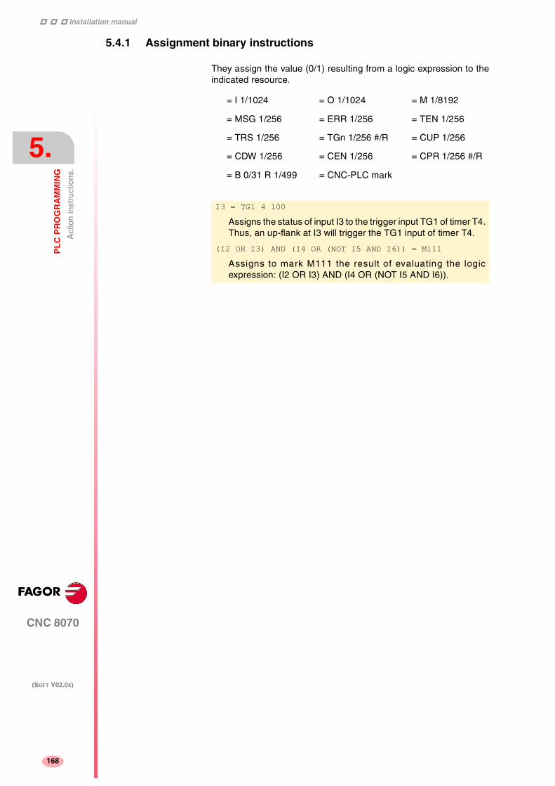
Installation manual
188
CNC 8070
5.
PL
C P
RO
GR
AM
MIN
G
Act
ion
inst
ruct
ions
.
(SOFT V02.0X)
168
5.4.1 Assignment binary instructions
They assign the value (0/1) resulting from a logic expression to theindicated resource.
= I 1/1024 = O 1/1024 = M 1/8192
= MSG 1/256 = ERR 1/256 = TEN 1/256
= TRS 1/256 = TGn 1/256 #/R = CUP 1/256
= CDW 1/256 = CEN 1/256 = CPR 1/256 #/R
= B 0/31 R 1/499 = CNC-PLC mark
I3 = TG1 4 100
Assigns the status of input I3 to the trigger input TG1 of timer T4.Thus, an up-flank at I3 will trigger the TG1 input of timer T4.
(I2 OR I3) AND (I4 OR (NOT I5 AND I6)) = M111
Assigns to mark M111 the result of evaluating the logicexpression: (I2 OR I3) AND (I4 OR (NOT I5 AND I6)).

Installation manual
CNC 8070
PL
C P
RO
GR
AM
MIN
G
Act
ion
inst
ruct
ions
.
5.
(SOFT V02.0X)
169
5.4.2 Conditional binary instructions
There are 3 instructions: SET, RES and CPL that are used to changethe status of the indicated resource.
The programming format is:
= SET If expression = "1", it sets the resource to "1".
If the result of the logic expression is a "1", it sets the indicatedresource to "1". If the result is "0", it does not change the resource.
= RES If expression = "1", it sets the resource to "0".
If the result of the logic expression is a "1", it sets the indicatedresource to "0". If the result is "0", it does not change the resource.
= CPL If expression = "1", it complements the resource
If the result of the logic expression is a "1", it complements the statusof the indicated resource. If the result is "0", it does not change theresource.
= SET
= RES
= CPL
I 1/1024
O 1/1024
M 1/8192
MSG 1/256
ERR 1/256
B 0/31 R 1/1024
CNC-PLC mark
CPS T2 EQ 100 = SET B0R100
When the timing of timer T2 reaches 100 milliseconds, it sets bit0 of register R100 to "1".
I12 OR NOT I22 = RES M55 = NOT RES M65
When the result of the logic expression is a "1", the PLC sets"M55 = 0”; but does not change M65.
If the result of the logic expression is a "0", the PLC does notchange M55; but it sets "M65 = 0".
DFU I8 OR DFD M22 = CPL B12R35
Every time an up-flank is detected at input I8 or down-flank ofmark M22, the PLC complements the state of bit 12 of registerR35.

Installation manual
188
CNC 8070
5.
PL
C P
RO
GR
AM
MIN
G
Act
ion
inst
ruct
ions
.
(SOFT V02.0X)
170
5.4.3 Sequence breaking action instructions
These actions interrupt the sequence of a program, resuming itsomewhere else in the program.
= JMP Unconditional jump
If the result of the logic expression is a "1", it jumps to the indicatedlabel. If the result is a "0", it goes on to the next program line.
Its syntax depends on how the label to jump to was defined
= JMP L123 If the label was defined as L123.
= JMP L_ASA2 If the label was defined as L_ASA2.
= CAL Call to a subroutine.
If the result of the logic expression is a "1", this action executes theindicated subroutine. If the result of the logic expression is a "0", thePLC will ignore this action and the program will go on without executingthat subroutine.
Once the subroutine execution is over, the PLC will continue at theaction instruction or executable instruction programmed after CAL.
Its syntax depends on how its associated subroutine was defined.
= CAL OILING If it was defined as SUB OILING.
= CAL L234 If it was defined as L234.
= CAL L_GEAR If it was defined as L_GEAR.
= RET Return or end of a subroutine.
If the result of the logic expression is a "1", the PLC will treat this actionlike an END instruction. If the result is a "0", the PLC will ignore it.
If while executing a subroutine, the PLC detects a validated RET, it willconclude the subroutine.
I8 = JMP L12
If I8=1 the program continues at L12 and it does not execute theintermediate blocks.
NOT M14 AND NOT B7R120 = O8
CPS T2 EQ 2000 = O12
L12
(I12 AND I23) OR M54 = O6
I2 = CAL L5 = O2
With I2=1, subroutine L5 will be executed and once executed,the PLC will set O2 to the value of input I2 (=1).
If I2=0, the subroutine is not executed and the PLC sets outputO2 to the status of input I2 (=0).

Installation manual
CNC 8070
PL
C P
RO
GR
AM
MIN
G
Act
ion
inst
ruct
ions
.
5.
(SOFT V02.0X)
171
5.4.4 Arithmetic action instructions
= MOV Move
It is used to move data from one PLC resource to another.
The programming format is:
The Origin and Destination codes indicate which format (binary orBCD) they have and in which format they will be deposited in thedestination resource. 4, 8, 12, 16, 20, 24, 28 or 32 bits may betransmitted.
If the codes and number of bits to be moved are not indicated, 32binary bits will be moved bit to bit (0032).
If the number to be converted from binary to BCD is larger than themaximum BCD, its value will be truncated ignoring the most significantbits.
The maximum BCD value that can be converted is: 9 (with 4 bits), 99(with 8), 999 (with 12), 9999 (with 16), 99999 (with 20), 999999 (with24), 9999999 (with 28) and 99999999 (con 32).
In these cases, it is recommended to make the move increasing thenumber of bits by using, if necessary, registers or marks inintermediate steps.
Origin Destination Origin code
Destination code
Bits to transmit
= MOV I1/1024O1/1024M1/8192
MSG1/256ERR1/256
T1/256
C1/256R1/1024
R CNC-PLC#
I1/1024O1/1024M1/8192
MSG1/256ERR1/256R1/1024
R CNC-PLC
0(Bin)1(BCD)
0(Bin)1(BCD)
322824201612
84
MOV I12 M100 0032 binary to binary in 32 bits.
MOV O21 R100 0012 binary to binary in 12 bits.
MOV C22 O23 0108 binary to BCD in 8 bits.
MOV T10 M112 1020 BCD to binary in 20 bits.
I11 = MOV I14 O16 108
If input I11 is "=1", the PLC moves the logic states of the 8 inputs(I14 plus the next 7) in BCD code to the 8 outputs (O16 and thenext 7) in binary code.
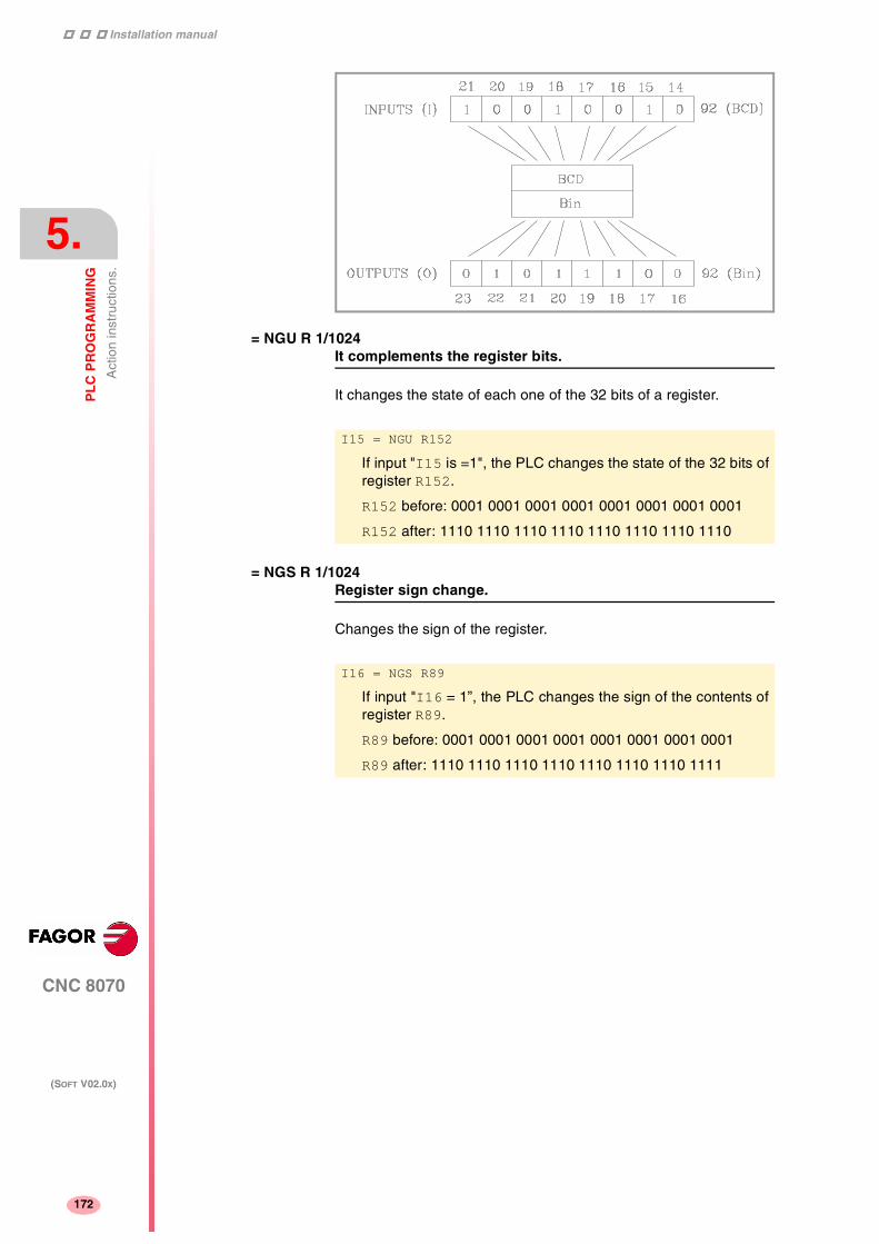
Installation manual
188
CNC 8070
5.
PL
C P
RO
GR
AM
MIN
G
Act
ion
inst
ruct
ions
.
(SOFT V02.0X)
172
= NGU R 1/1024It complements the register bits.
It changes the state of each one of the 32 bits of a register.
= NGS R 1/1024Register sign change.
Changes the sign of the register.
I15 = NGU R152
If input "I15 is =1", the PLC changes the state of the 32 bits ofregister R152.
R152 before: 0001 0001 0001 0001 0001 0001 0001 0001
R152 after: 1110 1110 1110 1110 1110 1110 1110 1110
I16 = NGS R89
If input "I16 = 1”, the PLC changes the sign of the contents ofregister R89.
R89 before: 0001 0001 0001 0001 0001 0001 0001 0001
R89 after: 1110 1110 1110 1110 1110 1110 1110 1111

Installation manual
CNC 8070
PL
C P
RO
GR
AM
MIN
G
Act
ion
inst
ruct
ions
.
5.
(SOFT V02.0X)
173
= ADS, = SBS, = MLS, = DVS, = MDSArithmetic operations
for adding (ADS), subtracting (SBS), multiplying (MLS), dividing (DVS)and calculating the module or remainder of a division (MDS).
Its programming format is:
“Operation” “1st operand” “2nd operand” “Result”.
The operands may be: Registers, CNC-PLC communicationregisters and numbers (#) in the ±2147483647 range or between0 and $FFFFFFFF.
The result of the operation may be stored in a register or in a CNC-PLC communication register.
Examples with R100=1234 and R101=100.
= ADS
= SBS
= MLS
= DVS
= MDS
R1/1024
R CNC-PLC
#
R1/1024
R CNC-PLC
#
R1/1024
R CNC-PLC
() = ADS R100 R101 R102 ; R102 = 1234 +100 = 1334
() = SBS R100 R101 R103 ; R103 = 1234 -100 = 1134
() = MLS R100 R101 R104 ; R104 = 1234 x 100 = 123400
() = DVS R100 R101 R105 ; R105 = 1234 : 100 = 12
() = MDS R100 R101 R106 ; R106 = 1234 MOD 100 = 34
() = ADS 1563 R101 R112 ; R112 = 1563 +100 = 1663
() = SBS R100 1010 R113 ; R113 = 1234 - 1010 = 224
() = MLS 1563 100 R114 ; R114 = 1563 x 100 = 156300
() = MLS SANALOG 10000 R115
= DVS R115 32767 R115 ; Spindle speed command in mV.

Installation manual
188
CNC 8070
5.
PL
C P
RO
GR
AM
MIN
G
Act
ion
inst
ruct
ions
.
(SOFT V02.0X)
174
5.4.5 Logic action instructions
= AND, = OR, = XORLogic operations
To perform logic operations: AND, OR and XOR between registercontents or between a register content and a number. The result isalways stored in a register.
Its programming format is:
= RR, = RL Register rotation
Register contents may be rotated to the right (RR) or (RL) to the leftand there are two types of rotations: type 1 (RR1 or RL1) and type 2(RR2 or RL2).
Rotation type 1 (RL1 or RR1):
It inserts a "0" at the least significant bit (RL1) or at the most significantbit (RR1), pushing the other bits of the register. The value of the lastbit disappears.
Rotation type 2 (RL2 or RR2):
Circular rotation of the register in the indicated direction.
AND
OR
XOR
R1/1024
R CNC-PLC
#
R1/1024
R CNC-PLC
#
R1/1024
R CNC-PLC
Examples with R200 = B1001 0010
R201 = B0100 0101
() = AND R200 R201 R202 ; R202 = B0
() = OR R200 R201 R203 ; R203 = B11010111
() = XOR R200 R201 R204 ; R204 = B11010111
() = AND B1111 R201 R205 ; R205 = B00000101
() = OR R200 B1111 R206 ; R206 = B10011111
() = XOR B1010 B1110 R207 ; R207 = B00000100

Installation manual
CNC 8070
PL
C P
RO
GR
AM
MIN
G
Act
ion
inst
ruct
ions
.
5.
(SOFT V02.0X)
175
Its programming format is:
The origin and destination registers must always be defined, evenwhen they are both the same. The number of repetitions indicates theconsecutive number of times the register will be rotated.
Origin Repetition Nr. Destination
RR1
RR2
RL1
RL2
R1/1024
R CNC-PLC
R1/1024
R CNC-PLC
0/31
R1/1024
R CNC-PLC
RR1 R100 1 R200
It does one type-1 right-hand rotation of R100 leaving the resultin R200.
RL2 R102 4 R101
It does one type-2 left-hand rotation of R102 leaving the resultin R101.

Installation manual
188
CNC 8070
5.
PL
C P
RO
GR
AM
MIN
G
Act
ion
inst
ruct
ions
.
(SOFT V02.0X)
176
5.4.6 Specific action instructions
= ERA Clears a group of resources.
It is used to clear or initialize a group of same-type resources. Indicatethe first and last resource to be erased.
Its programming format is:
When erasing a group of I, O, M, MSG, ERR or R, the PLC sets themall to "0".
Erasing a group of timers is like resetting them and erasing a groupof counters is like presetting with a "0" value.
This action is especially handy when executed in the first cycle module(CY1) in order to set the desired resources to their initial workconditions (states).
= PAR Parity of a register
It analyzes the type of parity of a register. If the register has EVENparity, this instruction sets the selected mark, message or error to "1"and to "0" if it has ODD parity.
Its programming format is:
= ERA I 1/1024
O 1/1024
M 1/8192
MSG 1/256
ERR 1/256
T 1/256
C 1/256
R 1/1024
1/1024
1/1024
1/8192
1/256
1/256
1/256
1/256
1/1024
I10 = ERA O5 12
If input "I10=1", the PLC sets outputs O5 through O12 (bothincluded) to "0".
I23 = ERA C15 18
If input "I23 =1”, the PLC presets counters C15 through C18(both included) to "0".
= PAR R1/1024
R CNC-PLC
M1/8192
MSG1/256
ERR1/256
M CNC-PLC
I15 = PAR R123 M222
If input "I15=1", the PLC analyzes register R123 and sets markM222 to "1" if EVEN parity or to "0" if ODD parity.

Installation manual
CNC 8070
PL
C P
RO
GR
AM
MIN
G
Act
ion
inst
ruct
ions
.
5.
(SOFT V02.0X)
177
= CNCRD Reading of internal CNC variables.
= CNCWR Writing of internal CNC variables.
Used to read (CNCRD) and write (CNCWR) the internal CNC variables.Their programming format is:
CNCRD (Variable, Register, Mark)
CNCWR (Register, Variable, Mark)
The CNCRD action loads the contents of the variable into the registerand the CNCWR action loads the contents of the register into thevariable. The mark is set to "1" at the beginning of the operation andit keeps its value until the end of the operation.
When using CNCRD to read the variables of the arithmetic parametersand those of the OEM, it returns the value multiplied by 10000 (floatmode reading).
When requesting information on a nonexistent variable (for examplethe position of an nonexistent axis), it will show the relevant errormessage. Likewise, when trying to read a value whose range isgreater than that of the PLC register, the CNC will return a zero valueand will issue the corresponding error message. Whenever an erroroccurs when reading a variable, the communication mark will remainat "1".
Synchronous and asynchronous variables
Synchronous variables are the ones resolved immediately whereasasynchronous variables are the ones requiring several cycle scans tobe resolved.
Example of how to access asynchronous variables:
<condition> AND NOT M11 = CNCRD (TM.TOOL, R11, M11)
do not repeat this consultation until it ends.
DFD M11 AND CPS R11 EQ 3 = ...
wait for the consultation to end before comparing the data.
Examples of how to access synchronous variables:
<condition> = CNCRD (G.FREAL, R12, M12)
CPS R12 GT 2000 = ...
No need to wait before consult ing the data becausesynchronous variables are resolved immediately
<condition> = CNCWR (R13, PLC.TIMER, M13)
It resets the clock enabled by the PLC with the value containedin register R13.

Installation manual
188
CNC 8070
5.
PL
C P
RO
GR
AM
MIN
G
Act
ion
inst
ruct
ions
.
(SOFT V02.0X)
178
= CNCEX Execution of a CNC block.
It may be used to execute a CNC block in the indicated channel,including calls to subroutines or to complete programs. It works likewhen executing a block in MDI. The restrictions for the execution ofcommands are the same as for the MDI blocks.
Its programming format is:
CNCEX (block, mark, channel)
The mark is set to "1" at the beginning of the operation and it keepsits value until the end of the operation. If the channel is not indicated,the block is executed in the first or main channel.
Once the block has been executed, the CNC channel activates theFREE mark to let the PLC know that it is ready to accept a new block.
Executing independent movements from the PLC. CommandsMOVEABS, MOVEADD and MOVEINF.
The movements of the independent axes may be programmed directlyor with the CNCEX command; however, it is not recommended to useboth methods in the same PLC program or subroutine.
The treatment for the execution of the commands is different and theorder they are executed might not be the desired one. The CNCEXcommand is executed through a CNC channel whereas the MOVE*commands are executed directly at the interpolator (usually fasterexecution).
... = CNCEX (G00 X0 Y0, M99, 2)
... = CNCEX (#CALL sub3.nc, M34)
The independent movements may be executed as follows: The two shouldnot be used in the same program or subroutine.
() = CNCEX(#MOVE ADD [X100,F100,NULL], M120,1)
() = MOVEADD(X,100000,100000,NULL)

Installation manual
CNC 8070
PL
C P
RO
GR
AM
MIN
G
Act
ion
inst
ruct
ions
.
5.
(SOFT V02.0X)
179
5.4.7 Action instruction of the electronic cam
= CAM ON Activate the electronic cam
= CAM OFF Cancel the electronic cam
The programming format for each of them is the following.
CAM ON (cam, master/"TIME", slave, master_off, slave_off, range_master, range_slave, type)
CAM OFF (slave)
Executing the CAM OFF command involves eliminating thesynchronization of the cam. Once this command has beenprogrammed, the cam ends when reaching the end of its profile.
Cam mode.
Two types of cams may be activated; cams in time or cams accordingto the position of the master axis. The activation instruction is the sameand it is selected by the call-parameters.
Cam number.
To activate a cam, it must have been previously defined at the cameditor, within the machine parameters.
Master axis activation range.
The cam is activated when the master axis is between the positions"master_off" and "master_off + range_master".
Range for the slave axis.
The cam applies it to the slave axis when the slave axis is between"slave_off" and "slave_off + range_slave".
This function has a specific manual.
This manual that you are reading now only offers some informationabout this function. Refer to the specific documentation to obtainfurther information regarding the requirements and operation of theelectronic cam.
Parameter Meaning
cam Cam number.
master Name of the master axis.
TIME Time cam. When programming "TIME" instead of anaxis name, the cam is interpreted as being a time cam.
slave Name of the slave axis.
master_off Offset for the master axis.
slave_off Offset for the slave axis.
range_master Master axis activation scale or range.
range_slave Slave axis activation scale or range.
type It defines the type of cam; periodic or not periodic. It isprogrammed using parameters "ONCE" (non-periodiccam) or "CONT" (periodic cam).

Installation manual
188
CNC 8070
5.
PL
C P
RO
GR
AM
MIN
G
Act
ion
inst
ruct
ions
.
(SOFT V02.0X)
180
Cam type.
Depending on the execution mode, the time cams and the positioncams may be of two different types; i.e. periodic or non-periodic. It isselected with the type parameter.
Non-periodic It is defined by assigning the "ONCE" value to thetype parameter.
This mode maintains the synchronization for therange defined for the master axis. If the masteraxis moves backwards or if it is a module, the slaveaxis will keep on executing the cam profile until thecancellation is programmed.
Periodic It is defined by assigning the "CONT" value to thetype parameter.
In this mode, when reaching the end of the rangeof the master axis, it calculates the offset toexecute the cam again shifted in the amount ofthat range. In other words, identical cams areexecuted along the path of the master axis.
If the master axis is a rotary module and the cam definition range isthat module, the two execution modes are equivalent.
Either mode maintains synchronization until the #CAM OFF commandis executed. When reaching that command, the execution of the camwill end the next time the end of the cam profile is reached.

Installation manual
CNC 8070
PL
C P
RO
GR
AM
MIN
G
Act
ion
inst
ruct
ions
.
5.
(SOFT V02.0X)
181
5.4.8 Action instructions for independent axes
= MOVE ABS Absolute positioning move
= MOVE ADD Incremental positioning move
= MOVE INF Infinite (endless) positioning move
The programming format for each of them is the following.
MOVE ABS (axis, pos, feed, blend)
MOVE ADD (axis, pos, feed, blend)
MOVE INF (axis, direction, feed, blend)
Position to reach.
With MOVE ABS it will be defined in absolute coordinates whereas withMOVE ADD it will be defined in incremental coordinates. Forpositioning, the zero offset active in the channel is ignored.
The moving direction is determined by the coordinate or the incrementprogrammed. For rotary axes, the moving direction is determined bythe type of axis. If it is unidirectional, it positions in the preset direction;otherwise, it positions via the shortest path.
Moving direction.
Moving direction. It is used with MOVE INF to execute an endless(infinite) movement until the axis limit is reached or until the movementis interrupted.
This function has a specific manual.
This manual that you are reading now only offers some informationabout this function. Refer to the specific documentation to obtainfurther information regarding the requirements and operation of theindependent axes.
Parameter Meaning
axis Axis to position.
pos Position to reach.
direction Moving direction. It is programmed with parameters"DIRPOS" (posit ive direct ion) or "DIRNEG"(negative direction).
feed Positioning feedrate
blend Dynamic blend with the next block It is programmedusing parameters "PRESENT", "NULL", "NEXT" or"WAITINPOS.

Installation manual
188
CNC 8070
5.
PL
C P
RO
GR
AM
MIN
G
Act
ion
inst
ruct
ions
.
(SOFT V02.0X)
182
Dynamic blend with the next block
It sets the feedrate used to reach the position (dynamic blend with thenext block). It is programmed with one of the following parameters.
PRESENT The axis reaches the indicated position at the feedrateindicated by the block itself.
NEXT The axis reaches the indicated position at the feedrateindicated in the next block.
NULL The axis reaches the indicated position at zero feedrate.
WAITINPOSThe axis reaches the indicated position at zero feedrateand it waits to be in position before executing the nextblock.
= FOLLOW ON Activates the synchronization movement
= FOLLOW OFF Cancels the synchronization movement.
The programming format for each of them is the following.
FOLLOW ON (master, slave, nratio, dratio, synctype)
FOLLOW OFF (slave)
.. = MOVE ABS (X, 50, 500, PRESENT)
.. = MOVE ABS (X, 100, 250, NEXT)
.. = MOVE ABS (X, 150, 125, NULL)
F
Pos
500
250
125
50mm 100mm 150mm
Parameter Meaning
master Name of the master axis.
slave Name of the slave axis.
nratio Numerator of the gear ratio. Turns of the slave axis.
dratio Denominator of the gear ratio. Rotations of themaster axis.
synctype Type of synchronism. It is programmed withparameters "POS" (position synchronism) or "VEL"(velocity synchronism).
Example from the PLC program.
FOLLOW ON (A1, Z, 3, 1, VEL)
FOLLOW OFF (Z)

Installation manual
CNC 8070
PL
C P
RO
GR
AM
MIN
G
Sum
mar
y pr
ogra
mm
ing
com
man
ds
5.
(SOFT V02.0X)
183
5.5 Summary programming commands
RESOURCES AVAILABLE AT THE PLC
Clocks
CNC-PLC communication marks.
CNC-PLC communication registers.
The register value may be treated as a decimal or hexadecimal("S") number. It is also possible to refer to a register bit using theletter s B (0/31) R (1/1024).
Inputs I1··1024
Outputs O1··1024
Marks M1··8192
Message mark MSG1··256
Error Mark ERR1··256
CLK1 1ms CLK100 100ms CLK1000 1s
CLK2 2ms CLK200 200ms CLK2000 2s
CLK4 4ms CLK400 400ms CLK4000 4s
CLK8 8ms CLK800 800ms CLK8000 8s
CLK16 16ms CLK1600 1.6s CLK16000 16s
CLK32 32ms CLK3200 3.2s CLK32000 32s
CLK64 64ms CLK6400 6.4s CLK64000 64s
CLK128 128ms CLK12800 12.8s CLK128000 128s
Timers: T1··256
Counters: C1··256
Registers: R1··1024

Installation manual
188
CNC 8070
5.
PL
C P
RO
GR
AM
MIN
G
Sum
mar
y pr
ogra
mm
ing
com
man
ds
(SOFT V02.0X)
184
DIRECTING INSTRUCTIONS
SIMPLE CONSULTING INSTRUCTIONS
FLANK DETECTION CONSULTING INSTRUCTIONS
PRG Main module.
CY1 First cycle module.
PE t Periodic module. It is executed every "t" milliseconds.
END End of module.
L Label L with up to 7 digits (L1 ... L9999999)
L_ with up to 8 characters (L_GEAR)
SUB Subroutine definition.
DEF Symbol definition.
PDEF External symbol definition.
REA The consultations will use real values.
IMA The consultations will use image values.
Inputs I1··1024
Outputs O1··1024
Marks M1··8192
Message mark MSG1··256
Error Mark ERR1··256
Timers (status) T1··256
Counters (status) C1··256
Register bit B0··31 R1··1024
CNC-PLC communication marks
DFU Up flank detection.
DFD Down flank detection.
DFU I1··1024
DFD O1··1024
M1··8192
MSG1··256
ERR1··256
B0··31 R1··1024
CNC-PLC communication marks
Clock marks (CLK)

Installation manual
CNC 8070
PL
C P
RO
GR
AM
MIN
G
Sum
mar
y pr
ogra
mm
ing
com
man
ds
5.
(SOFT V02.0X)
185
COMPARISON CONSULTING INSTRUCTIONS
OPERATORS
ASSIGNMENT BINARY ACTION INSTRUCTIONS
CONDITIONAL BINARY ACTION INSTRUCTIONS
CPS to do the following comparisons.
CPS T1··256 GT T1··256
C1··256 GE C1··256
R1··1024 EQ R1··1024
R CNC-PLC NE R CNC-PLC
# LE #
LT
NOT Negates the result of the consultation.
AND Logic function "AND".
OR Logic function "OR”.
XOR Logic "Exclusive OR" function.
"\" New line.
"( )" Consulting instruction whose value is always "1".
= I 1/1024 = O 1/1024 = M 1/8192
= MSG 1/256 = ERR 1/256 = TEN 1/256
= TRS 1/256 = TGn 1/256 #/R = CUP 1/256
= CDW 1/256 = CEN 1/256 = CPR 1/256 #/R
= B 0/31 R 1/1024 = CNC-PLC mark
= SET If expression = "1", it sets the resource to "1"
= RES If expression = "1", it sets the resource to "0"
= CPL If expression = "1", it complements the resource.
<Resource>
= SET <Resource> I 1/1024
= RES <Resource> O 1/1024
= CPL <Resource> M 1/8192
MSG 1/256
ERR 1/256
B 0/31 R 1/1024
CNC-PLC mark
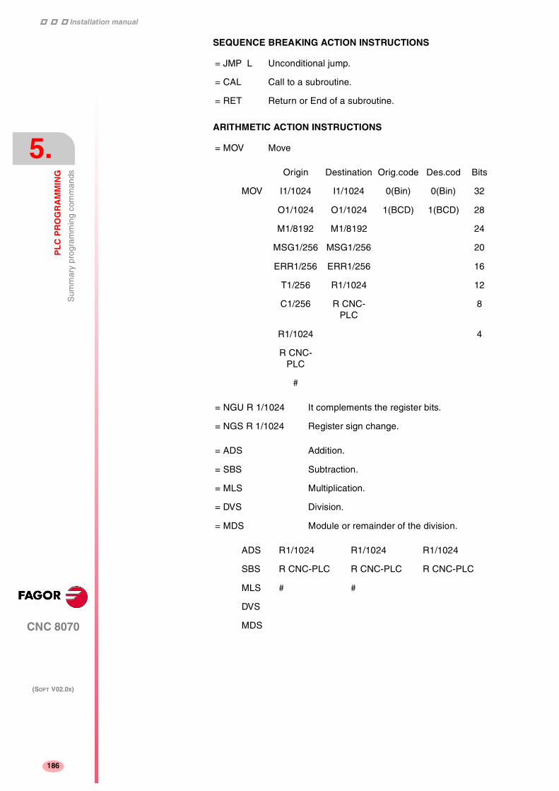
Installation manual
188
CNC 8070
5.
PL
C P
RO
GR
AM
MIN
G
Sum
mar
y pr
ogra
mm
ing
com
man
ds
(SOFT V02.0X)
186
SEQUENCE BREAKING ACTION INSTRUCTIONS
ARITHMETIC ACTION INSTRUCTIONS
= JMP L Unconditional jump.
= CAL Call to a subroutine.
= RET Return or End of a subroutine.
= MOV Move
Origin Destination Orig.code Des.cod Bits
MOV I1/1024 I1/1024 0(Bin) 0(Bin) 32
O1/1024 O1/1024 1(BCD) 1(BCD) 28
M1/8192 M1/8192 24
MSG1/256 MSG1/256 20
ERR1/256 ERR1/256 16
T1/256 R1/1024 12
C1/256 R CNC-PLC
8
R1/1024 4
R CNC-PLC
#
= NGU R 1/1024 It complements the register bits.
= NGS R 1/1024 Register sign change.
= ADS Addition.
= SBS Subtraction.
= MLS Multiplication.
= DVS Division.
= MDS Module or remainder of the division.
ADS R1/1024 R1/1024 R1/1024
SBS R CNC-PLC R CNC-PLC R CNC-PLC
MLS # #
DVS
MDS

Installation manual
CNC 8070
PL
C P
RO
GR
AM
MIN
G
Sum
mar
y pr
ogra
mm
ing
com
man
ds
5.
(SOFT V02.0X)
187
LOGIC ACTION INSTRUCTIONS
SPECIFIC ACTION INSTRUCTIONS
CNCRD (Variable, R1/1024, M1/8192)
CNCWR (R1/1024, Variable, M1/8192)
= AND Logic operation "AND".
= OR Logic operation "OR".
= XOR Logic operation "XOR".
AND R1/1024 R1/1024 R1/1024
OR R CNC-PLC R CNC-PLC R CNC-PLC
XOR # #
= RR 1/2 Clockwise register rotation.
= RL 1/2 Counterclockwise register rotation.
Origin Repetition Nr. Destination
RR1 R1/1024 R1/1024 R1/1024
RR2 R CNC-PLC R CNC-PLC R CNC-PLC
RL1 0/31
RL2
= ERA Erases or resets a group of resources.
ERA I 1/1024 1/1024
O 1/1024 1/1024
M 1/8192 1/8192
MSG 1/256 1/256
ERR 1/256 1/256
T 1/256 1/256
C 1/256 1/256
R 1/1024 1/1024
= CNCRD Reading of internal CNC variables.
= CNCWR Writing of internal CNC variables.
= PAR Parity of a register.
PAR R1/1024 M1/8192
R CNC-PLC MSG1/256
ERR1/256
M CNC-PLC
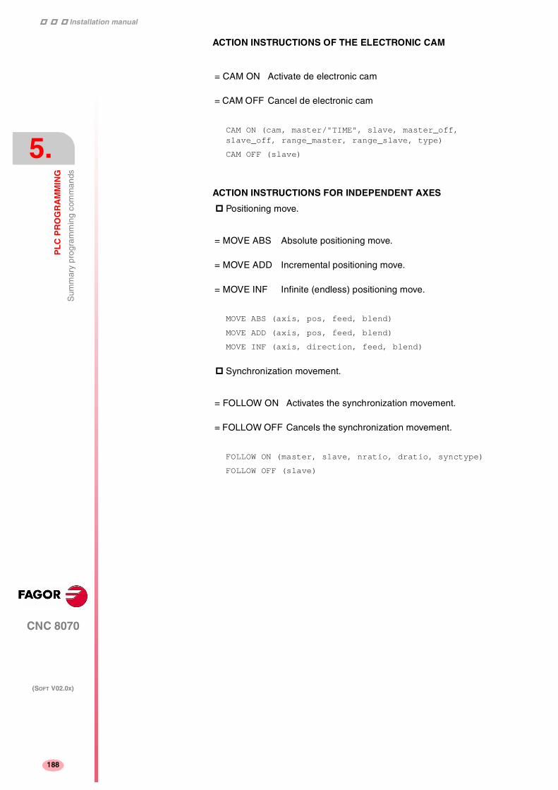
Installation manual
188
CNC 8070
5.
PL
C P
RO
GR
AM
MIN
G
Sum
mar
y pr
ogra
mm
ing
com
man
ds
(SOFT V02.0X)
188
ACTION INSTRUCTIONS OF THE ELECTRONIC CAM
CAM ON (cam, master/"TIME", slave, master_off, slave_off, range_master, range_slave, type)
CAM OFF (slave)
ACTION INSTRUCTIONS FOR INDEPENDENT AXES
Positioning move.
MOVE ABS (axis, pos, feed, blend)
MOVE ADD (axis, pos, feed, blend)
MOVE INF (axis, direction, feed, blend)
Synchronization movement.
FOLLOW ON (master, slave, nratio, dratio, synctype)
FOLLOW OFF (slave)
= CAM ON Activate de electronic cam
= CAM OFF Cancel de electronic cam
= MOVE ABS Absolute positioning move.
= MOVE ADD Incremental positioning move.
= MOVE INF Infinite (endless) positioning move.
= FOLLOW ON Activates the synchronization movement.
= FOLLOW OFF Cancels the synchronization movement.

6
189
CNC 8070
(SOFT V02.0X)
CNC-PLC COMMUNICATION
With the data exchange between the CNC and the PLC, it is possibleto:
• Control the logic CNC inputs and outputs in peripheral mode usingspecific PLC marks and registers.
• Transfer auxiliary M, H and S functions from the CNC to the PLC.
• Generate messages and errors at the CNC using PLC marks.
• Read and modify internal CNC variables from the PLC.
• Access all PLC resources from any part-program.
• Monitor PLC resources on the CNC screen.
Abbreviations used in this chapter
M and H functions with channels
The M and H functions are exchanged by channel. When using severalchannels, the marks and registers of these functions must indicate thechannel number they refer to. If no channel number is indicated, themarks and registers refer to the first channel.
S functions with multiple spindles
The exchange of S functions is independent from the channel. Whenusing several spindles, the marks and registers of these functionsrefer to the spindle number. The spindle number is determined by itslogic number.
(=0) Low logic level.
(=1) High logic level.
(g.m.p.) General machine parameter.
(a.m.p.) Machine parameter for Axes and Spindles.
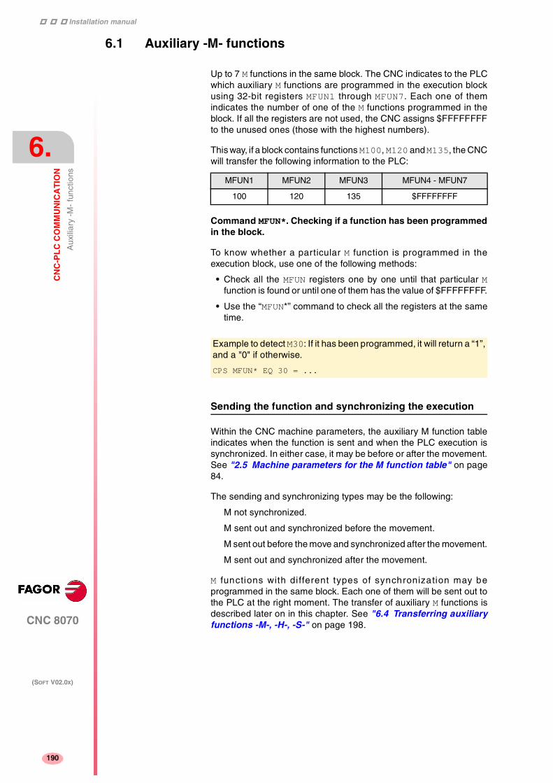
Installation manual
204
CNC 8070
6.
CN
C-P
LC
CO
MM
UN
ICA
TIO
N
Aux
iliar
y -M
- fu
nctio
ns
(SOFT V02.0X)
190
6.1 Auxiliary -M- functions
Up to 7 M functions in the same block. The CNC indicates to the PLCwhich auxiliary M functions are programmed in the execution blockusing 32-bit registers MFUN1 through MFUN7. Each one of themindicates the number of one of the M functions programmed in theblock. If all the registers are not used, the CNC assigns $FFFFFFFFto the unused ones (those with the highest numbers).
This way, if a block contains functions M100, M120 and M135, the CNCwill transfer the following information to the PLC:
Command MFUN*. Checking if a function has been programmedin the block.
To know whether a particular M function is programmed in theexecution block, use one of the following methods:
• Check all the MFUN registers one by one until that particular Mfunction is found or until one of them has the value of $FFFFFFFF.
• Use the “MFUN*” command to check all the registers at the sametime.
Sending the function and synchronizing the execution
Within the CNC machine parameters, the auxiliary M function tableindicates when the function is sent and when the PLC execution issynchronized. In either case, it may be before or after the movement.See "2.5 Machine parameters for the M function table" on page84.
The sending and synchronizing types may be the following:
M not synchronized.
M sent out and synchronized before the movement.
M sent out before the move and synchronized after the movement.
M sent out and synchronized after the movement.
M functions with di fferent types of synchronization may beprogrammed in the same block. Each one of them will be sent out tothe PLC at the right moment. The transfer of auxiliary M functions isdescribed later on in this chapter. See "6.4 Transferring auxiliaryfunctions -M-, -H-, -S-" on page 198.
MFUN1 MFUN2 MFUN3 MFUN4 - MFUN7
100 120 135 $FFFFFFFF
Example to detect M30: If it has been programmed, it will return a “1”,and a "0" if otherwise.
CPS MFUN* EQ 30 = ...

Installation manual
CNC 8070
CN
C-P
LC
CO
MM
UN
ICA
TIO
N
Aux
iliar
y -M
- fu
nctio
ns
6.
(SOFT V02.0X)
191
The functions may be set as follows:
M11 not synchronized.
M12 is sent and synchronized before the movement.
M13 is sent before and synchronized after the movement.
M14 is sent and synchronized after the movement.
When executing a block like this:
X100 F1000 M11 M12 M13 M14
The functions are transferred as follows:
1. sends the M11, M12 and M13 out to the PLC.
2. waits for the PLC to execute the M12.
3. moves the axis to X100.
4. sends function M14 to the PLC.
5. waits until the PLC executes the M13 and M14.

Installation manual
204
CNC 8070
6.
CN
C-P
LC
CO
MM
UN
ICA
TIO
N
Aux
iliar
y -M
- fu
nctio
ns
(SOFT V02.0X)
192
6.1.1 Special considerations with the multi-spindle option and channels
The CNC may have up to 4 channels and each channel can executea part-program in parallel with the rest. This means that each channelcan execute seven auxiliary functions simultaneously. The auxiliaryfunctions executed from each channel are treated independently; todo that, each channel has its own marks and registers.
Since each channel may have four spindles, it is possible to programin the same block 6 non-spindle-related M functions, the startup of allfour spindles M3 / M4 and a speed for each of them involving anautomatic gear change. This means that, because some functions aregenerated automatically, it may exceed the maximum of sevenauxiliary functions per block. In this case, the CNC will send the Mfunctions out to the PLC in two stages.
Marks and registers in the channels option
Each channel has 32-bit registers MFUN1 a MFUN7 to indicate to thePLC which auxiliary M functions are programmed in the executionblock.
MFUN1C1 - MFUN7C1 for the first channel.
MFUN1C2 - MFUN7C2 for the second channel.
MFUN1C3 - MFUN7C3 for the third channel.
MFUN1C4 - MFUN7C4 for the fourth channel.
Each one of them indicates the number of one of the M functionsprogrammed in the block. If all the registers are not used, the CNCassigns $FFFFFFFF to the unused ones (those with the highestnumbers).
This way, if functions M100 and M135 are programmed in the firstchannel and functions M88 and M75 in the second channel, the CNCwill transfer the following data.
MFUN1C1 MFUN2C1 MFUN3C1 - MFUN7C1
100 135 $FFFFFFFF
MFUN1C2 MFUN2C2 MFUN3C2 - MFUN7C2
88 75 $FFFFFFFF

Installation manual
CNC 8070
CN
C-P
LC
CO
MM
UN
ICA
TIO
N
Aux
iliar
y -M
- fu
nctio
ns
6.
(SOFT V02.0X)
193
Commands MFUNC1* - MFUNC4*. Checking if a function has beenprogrammed in the channel.
To know whether a particular M function is programmed in theexecution block, use one of the following methods:
• Check all the MFUN registers one by one until that particular Mfunction is found or until one of them has the value of $FFFFFFFF.
• Use one of the following commands to check all the MFUN registersof the channel at the same time.
MFUNC1* For channel 1
MFUNC2* For channel 2.
MFUNC3* For channel 3.
MFUNC4* For channel 4.
Example for detecting M04 in channel 1. If programmed, it will returna "1" and a "0" if otherwise.
CPS MFUNC1* EQ 4 = ...

Installation manual
204
CNC 8070
6.
CN
C-P
LC
CO
MM
UN
ICA
TIO
N
Aux
iliar
y H
func
tions
(SOFT V02.0X)
194
6.2 Auxiliary H functions
Up to 7 M and 7 H functions may be programmed in a block. Thetreatment of the auxiliary H functions is similar to the M functionswithout synchronization.
The CNC indicates to the PLC which auxiliary H functions areprogrammed in the execution block using 32-bit registers HFUN1through HFUN7. Each one of them indicates the number of one of theH functions programmed in the block. If all the registers are not used,the CNC assigns $FFFFFFFF to the unused ones (those with thehighest numbers).
This way, if a block contains functions H12, H20 and H35, the CNC willtransfer the following information to the PLC:
Command HFUN*. Checking if a function has been programmedin the block.
To know whether a particular H function is programmed in theexecution block, use one of the following methods:
• Check all the HFUN registers one by one until that particular Hfunction is found or until one of them has the value of $FFFFFFFF.
• Use the “HFUN*” format to check all the HFUN registers at the sametime.
Sending and synchronizing the function
The H functions are not synchronized and are sent out to the PLC atthe beginning of block execution.
The transfer of auxiliary H functions is described later on in thischapter. See "6.4 Transferring auxiliary functions -M-, -H-, -S-" onpage 198.
HFUN1 HFUN2 HFUN3 HFUN4 - HFUN7
12 20 35 $FFFFFFFF
Example to detect H77: If it has been programmed, it will return a “1”,and a "0" if otherwise.
CPS HFUN* EQ 77 = ...
When executing a block like this:
X100 F1000 H11 H12
The functions are transferred as follows:
1. functions H11 and H12 are sent out to the PLC
2. It does not wait for confirmation and the CNC moves the axis toX100.

Installation manual
CNC 8070
CN
C-P
LC
CO
MM
UN
ICA
TIO
N
Aux
iliar
y H
func
tions
6.
(SOFT V02.0X)
195
6.2.1 Special considerations with the multi-spindle option and channels
The CNC may have up to 4 channels and each channel can executea part-program in parallel with the rest. This means that each channelcan execute seven auxiliary functions simultaneously. The auxiliaryfunctions executed from each channel are treated independently; todo that, each channel has its own marks and registers.
Marks and registers in the channels option
Each channel has 32-bit registers HFUN1 to HFUN7 to indicate to thePLC which auxiliary H functions are programmed in the executionblock.
HFUN1C1 - HFUN7C1 for the first channel.
HFUN1C2 - HFUN7C2 for the second channel.
HFUN1C3 - HFUN7C3 for the third channel.
HFUN1C4 - HFUN7C4 for the fourth channel.
Each one of them indicates the number of one of the H functionsprogrammed in the block. If all the registers are not used, the CNCassigns $FFFFFFFF to the unused ones (those with the highestnumbers).
This way, if functions H10 and H13 are programmed in the first channeland functions H8 and H10in the second channel, the CNC will transferthe following data.
Commands HFUNC1* - HFUNC4*. Checking if a function has beenprogrammed in the channel.
To know whether a particular H function is programmed in theexecution block, use one of the following methods:
• Check all the HFUN registers one by one until that particular Hfunction is found or until one of them has the value of $FFFFFFFF.
• Use one of the following commands to check all the HFUN registersof the channel at the same time.
HFUNC1* For channel 1
HFUNC2* For channel 2.
HFUNC3* For channel 3.
HFUNC4* For channel 4.
HFUN1C1 HFUN2C1 HFUN3C1 - HFUN7C1
10 13 $FFFFFFFF
HFUN1C2 HFUN2C2 HFUN3C2 - HFUN7C2
8 10 $FFFFFFFF

Installation manual
204
CNC 8070
6.
CN
C-P
LC
CO
MM
UN
ICA
TIO
N
Aux
iliar
y S
func
tion
(SOFT V02.0X)
196
6.3 Auxiliary S function
The auxiliary S function indicates the spindle turning speed with M03and M04 or the angular position with M19.
The S function with M3 and M4 is always executed at the beginning ofthe block and the CNC waits for confirmation before going onexecuting the program. When working with M19, the CNC treats thespindle like a regular linear axis. It only sends the M19 out to the PLC.
The CNC uses 32-bit register SFUN1 to indicate to the PLC the valueof the S function programmed in the block. If not programmed, thevalue of $FFFFFFFF is sent out. The SFUN command only assumesthe value of the programmed S if spindle parameter SPDLTIME isother than zero.
The transfer of the S function is described later on in this chapter. See"6.4 Transferring auxiliary functions -M-, -H-, -S-" on page 198.

Installation manual
CNC 8070
CN
C-P
LC
CO
MM
UN
ICA
TIO
N
Aux
iliar
y S
func
tion
6.
(SOFT V02.0X)
197
6.3.1 Special considerations with the multi-spindle option and channels
The CNC may have up to four spindles. All of them may be controlledindependently in the same block; in other words, each spindle may begiven a different command.
When using channels, the spindles may be distributed indistinctlybetween them. In this case, a channel can control a spindle of anotherchannel. The marks and registers refer to the spindle regardless of thechannel they belong to.
The spindle number is determined by its logic number that is set bythe order they were defined in the machine parameter SPDLNAME.
Marks and registers in the multi-spindle version
The CNC indicates to the PLC which S functions are programmed inthe execution block using 32-bit registers SFUN1 through SFUN4.These registers refer to the spindle number; they are independentfrom the channel where the spindle is.
Each one of them indicates the value of one of the S functionsprogrammed. If all the registers are not used, the CNC assigns$FFFFFFFF to the unused ones (those with the highest numbers).
This way, if a block contains functions S1000 and S1=550, the CNCwill transfer the following information to the PLC:
Commands SP1FUN* - SP4FUN*. Check if an auxiliary functionhas been programmed for a spindle.
Considering the possible channels/spindles combinations, thesefunctions are available to make it easier to manage the auxiliary Mfunctions associated with each spindle. Each one indicates if any M3,M4, etc. type M function has been programmed in any channel.
SP1FUN* For the spindle 1.
SP2FUN* For the spindle 2.
SP3FUN* For the spindle 3.
SP4FUN* For the spindle 4.
SFUN1 SFUN2 SFUN3 SFUN4
1000 550 $FFFFFFFF $FFFFFFFF
Checks if the M5 function has been sent to spindle 1 from a channel.
CPS SP1FUN* EQ 5 = ...

Installation manual
204
CNC 8070
6.
CN
C-P
LC
CO
MM
UN
ICA
TIO
N
Tra
nsfe
rrin
g au
xilia
ry fu
nctio
ns -
M-,
-H
-, -
S-
(SOFT V02.0X)
198
6.4 Transferring auxiliary functions -M-, -H-, -S-
The M and H functions are transferred per channel. Transferring Sfunctions does not depend on the channel.
When executing a block that contains M, H, S functions, the followinginformation is transferred to the PLC.
Transferring -M- functions
The CNC assigns the numbers of the M functions programmed in theblock to registers MFUN1 through MFUN7 Some M functions have anassociated function that is activated when sending the M to the PLC.
M00 M01 M02 M03 M04
M05 M06 M08 M09 M19
M30 M41 M42 M43 M44
The CNC activates the general logic output MSTROBE to "tell" the PLCthat it must execute them. This mark is kept high (=1) for a time periodindicated by (g.m.p.) MINAENDW.
Depending on the type of synchronization, the CNC will either wait ornot for the general input AUXEND to be activated indicating the end ofthe PLC execution. The type of synchronization is defined in themachine parameters See "2.5 Machine parameters for the Mfunction table" on page 84.
The CNC cancels the general logic output “MSTROBE” to conclude theexecution.
Transferring -H- functions
The CNC assigns the numbers of the H functions programmed in theblock to registers HFUN7 through MFUN7
The CNC activates the general logic output HSTROBE to "tell" the PLCthat it must execute them. This mark is kept high (=1) for a time periodindicated by (g.m.p.) MINAENDW.
After this time period, the CNC considers its execution completedbecause there is no synchronization.
When sending several blocks in a row just having H functions, the CNCwaits twice the time indicated in g.m.p. MINAENDW.
N10 H60
N20 H30 H18
N30 H40

Installation manual
CNC 8070
CN
C-P
LC
CO
MM
UN
ICA
TIO
N
Tra
nsfe
rrin
g au
xilia
ry fu
nctio
ns -
M-,
-H
-, -
S-
6.
(SOFT V02.0X)
199
Transferring -S- functions
The CNC assigns the values of the S programmed in each spindle toregisters SFUN1 through SFUN4.
The CNC activates the general logic output SSTROBE to "tell" the PLCthat it must execute it. The CNC waits for the general input AUXENDto be activated indicating the end of the PLC execution.
The CNC cancels the general logic output “SSTROBE” to conclude theexecution.

Installation manual
204
CNC 8070
6.
CN
C-P
LC
CO
MM
UN
ICA
TIO
N
Tra
nsfe
rrin
g au
xilia
ry fu
nctio
ns -
M-,
-H
-, -
S-
(SOFT V02.0X)
200
6.4.1 Synchronized transfer
This type of transfer takes place with the S function and with the Mfunctions set with synchronization. See "2.5 Machine parametersfor the M function table" on page 84.
When the PLC is requested to execute several M or S functions at thesame time, the corresponding SSTROBE or MSTROBE signals areactivated; but the CNC waits for a single “AUXEND” signal to end allof them.
Transferring -M- functions
1. The CNC indicates in registers MFUN1 a MFUN7 of the channel theM functions programmed in the block and it activates the MSTROBEmark so the PLC executes them.
2. The PLC must deactivate the AUXEND mark to let the CNC knowthat the execution has begun.
3. Once the required auxiliary functions have been executed, the PLCmust activate the AUXEND mark to let the CNC know that theexecution has ended.
The AUXEND mark must be kept high (=1) longer than the timeperiod established by (g.m.p.) MINAENDW.
4. After this time, the CNC deactivates the MSTROBE mark thusending the execution of the function.
Transferring -S- functions
1. The CNC indicates in registers SFUN1 through SFUN4 the S valueprogrammed in the block and activates the SSTROBE mark so thePLC executes them.
2. The PLC must deactivate the AUXEND mark to let the CNC knowthat the execution has begun.
3. After selecting the requested S, the PLC must activate the AUXENDmark to let the CNC know that the execution has ended.
The AUXEND mark must be kept high (=1) longer than the timeperiod established by (g.m.p.) MINAENDW.
4. After this time, the CNC deactivates the SSTROBE mark thusending the execution of the function.
AUXEND
1 2 43
MINAENDW
SSTROBEMSTROBE

Installation manual
CNC 8070
CN
C-P
LC
CO
MM
UN
ICA
TIO
N
Tra
nsfe
rrin
g au
xilia
ry fu
nctio
ns -
M-,
-H
-, -
S-
6.
(SOFT V02.0X)
201
6.4.2 Non-synchronized transfer
This type of transfer takes place with the H function and with the Mfunctions set without synchronization. See "2.5 Machineparameters for the M function table" on page 84.
Transferring -M- functions
1. The CNC indicates in registers MFUN1 a MFUN7 of the channel theM functions programmed in the block and it activates the MSTROBEmark so the PLC executes them.
2. The CNC keeps the MSTROBE mark high (=1) for a time periodindicated by (g.m.p.) MINAENDW.
3. After this time, the CNC goes on executing the program regardlessof the time required by the PLC to execute that function.
Transferring -H- functions
1. The CNC indicates in registers HFUN1 a HFUN7 of the channel theH functions programmed in the block and it activates the HSTROBEmark so the PLC executes them.
2. The CNC keeps the HSTROBE mark high (=1) for a time periodindicated by (g.m.p.) MINAENDW.
3. After this time, the CNC goes on executing the program regardlessof the time required by the PLC to execute that function.
Considerations for transferring these functions
The value of (g.m.p.) MINAENDW should be the same or longer thanthe PLC program execution period (g.m.p.) PRGFREQ in order toensure that the PLC detects that signal.
When sending non-synchronized H or M functions corresponding toconsecutive blocks of the same program, the CNC waits betweenblocks for a time period indicated by MINANEDW so the PLC can readall the functions.
PLC
1 2 3
MINAENDW
SSTROBEMSTROBE
EXECUTION

Installation manual
204
CNC 8070
6.
CN
C-P
LC
CO
MM
UN
ICA
TIO
N
Dis
play
ing
PLC
err
ors
and
mes
sage
s
(SOFT V02.0X)
202
6.5 Displaying PLC errors and messages
The PLC has 256 marks for displaying messages and another 256marks for displaying errors at the CNC. When the mark is high (=1)the message or the error is active.
MSG1 - MSG256 for displaying messages.
ERR1 - ERR256 for displaying errors.
There is a message and error table where each message or error mayhave associated the following:
• A text ("Message" field).
• In the case of messages, if it is only shown at the window for PLCmessages or it is also shown to full screen ("Display" fieldselected).
• In the case of messages, a file with additional information ("help"field) It may be a "bmp, txt, jpg, gif, htm, html or avi" type file.
For more information on how to edit this table, refer to the operationmanual.
PLC messages
When activating one of the marks MSG1 through MSG256, the CNCwindow for PLC messages shows the message number and itsassociated text.
If the "Display" field is selected, the screen shows the additionalinformation file, or a blue window if otherwise, with the text of themessage. To close this window, press [ESC].
When there are more than one message activated, it always showsthe one with the highest priority (the one with the lowest number). ThePLC-messages window shows the "+" sign meaning that there aremore messages activated by the PLC. To display the whole list, press[CTRL] + [M].

Installation manual
CNC 8070
CN
C-P
LC
CO
MM
UN
ICA
TIO
N
Dis
play
ing
PLC
err
ors
and
mes
sage
s
6.
(SOFT V02.0X)
203
Displaying errors
When activating one of the marks ERR1 through ERR256, the CNCinterrupts the execution of the part-program and it displays the errornumber and its associated text in the middle of the screen.
External inputs should be used to activate and deactivate error marks,thus preventing the CNC from receiving those errors at every new PLCcycle scan.

Installation manual
204
CNC 8070
6.
CN
C-P
LC
CO
MM
UN
ICA
TIO
N
Dis
play
ing
PLC
err
ors
and
mes
sage
s
(SOFT V02.0X)
204

7
205
CNC 8070
(SOFT V02.0X)
LOGIC CNC INPUTS AND OUTPUTS
CNC's physical inputs and outputs are the set of system inputs andoutputs that are governed by the PLC and communicate with theoutside world through CNC connectors.
The CNC also has a number of logic inputs and outputs to exchangethe internal data with the marks and registers of the PLC. This way,the PLC has access to some internal CNC data.
Each of these logic inputs and outputs may be referred to using itsassociated mnemonic. The mnemonics that begin with a "_" signindicate that the signal is active low.
CNCREADY _ALARM
AUXEND _EMERGEN
MANUAL _STOP
The CNC's logic outputs or PLC consulting signals are grouped into:
• General consulting signals.
• Axis consulting signals.
• Spindle consulting signals.
• Consultation signals of the independent interpolator.
• Tool manager consulting signals.
• Keystroke consulting signals.
The CNC's logic inputs or signals that may be modified via PLC aregrouped into:
• General modifiable signals.
• Axis modifiable signals.
• Spindle modifiable signals.
• Modifiable signals of the independent interpolator.
• Tool manager modifiable signals.
• Keystroke modifiable signals.
Abbreviations used in this chapter
(=0) Low logic level.
(=1) High logic level.
(g.m.p.) General machine parameter.
(a.m.p.) Machine parameter for Axes and Spindles

Installation manual
247
CNC 8070
7.
LO
GIC
CN
C IN
PU
TS
AN
D O
UT
PU
TS
Gen
eral
con
sulti
ng s
igna
ls
(SOFT V02.0X)
206
7.1 General consulting signals
CNCREADY This mark indicates the CNC status. It is set to "0" when the CNC isin an error state (red status window) and to "1" if otherwise.
Include this mark in the PLC maneuver to enable the drives.
START There is one mark for each channel. The mnemonics for each channelare the following.
STARTC1 (can also be programmed as START)
STARTC2 STARTC3 STARTC4
The CNC channel sets this mark high (=1) to indicate to the PLC thatthe START key has been pressed at the operator panel.
If the rest of the conditions are met (hydraulic, safety, etc.), the PLCmust set the CYSTART mark high (=1) in order for the program to startrunning. See "CYSTART" on page 229.
FHOUT There is one mark for each channel. The mnemonics for each channelare the following.
FHOUTC1 (can also be programmed as FHOUT)
FHOUTC2 FHOUTC3 FHOUTC4
The CNC channel sets this mark high (=1) when the execution of thepart-program is interrupted. To interrupt and later resume theexecution of a program, proceed as follows:
• If the "_STOP" mark has been set low (=0).
To resume execution, set "_STOP" high (=1) and press the [START]key.
• If the "_FEEDHOL" mark is low (=0).
To resume execution, set "_FEEDHOL" high (=1).
RESETOUT There is one mark for each channel. The mnemonics for each channelare the following.
RESETOUTC1 (can also be programmed as RESETOUT)
RESETOUTC2 RESETOUTC3 RESETOUTC4
When pressing the [RESET] key or when the PLC activates the"RESETIN" mark (=1), the CNC assumes the initial conditions andsets the "RESETOUT" mark high (=1). This mark stays high (=1) for atime period set by (g.m.p.) MINAENDW. See "RESETIN" on page 230.
CNCREADY AND (rest of conditions) = O1
If there are no errors, output O1 will be high (=1).
START AND (rest of conditions) = CYSTART

Installation manual
CNC 8070
LO
GIC
CN
C IN
PU
TS
AN
D O
UT
PU
TS
Gen
eral
con
sulti
ng s
igna
ls
7.
(SOFT V02.0X)
207
_ALARM There is one mark for each channel. The mnemonics for each channelare the following.
_ALARMC1 (can also be programmed as _ALARM)
_ALARMC2 _ALARMC3 _ALARMC4
The CNC channel sets this mark low (=0) when there is an alarm oran emergency generated by the CNC channel. It is not activated whenthe emergency is caused by the PLC by activating the _EMERGENmark (=0).
It goes back high (=1) when the CNC channel message is removedand the cause of the alarm has been eliminated.
There is no output associated with this mark. The following exampleshows how to associate output O1.
MANUAL There is one mark for each channel. The mnemonics for each channelare the following.
MANUALC1 (can also be programmed as MANUAL)
MANUALC2 MANUALC3 MANUALC4
The CNC sets this mark high (=1) when the Manual Operation (JOG)mode is selected.
AUTOMAT There is one mark for each channel. The mnemonics for each channelare the following.
AUTOMATC1 (can also be programmed as AUTOMAT)
AUTOMATC2 AUTOMATC3 AUTOMATC4
The CNC channel sets this mark high (=1) when the automaticoperation mode is selected.
MDI There is one mark for each channel. The mnemonics for each channelare the following.
MDIC1 (can also be programmed as MDI)
MDIC2 MDIC3 MDIC4
The CNC sets this mark high (=1) when the MDI (Manual Data Input)mode is selected.
• If the MDI mode is selected while in automatic mode, the AUTOMATand MDI marks will be activated.
• If the MDI mode is selected while in manual (jog) mode, theMANUAL and MDI marks will be activated.
_ALARM AND (rest of conditions) = O1
If there are no errors, output O1 will be high (=1)

Installation manual
247
CNC 8070
7.
LO
GIC
CN
C IN
PU
TS
AN
D O
UT
PU
TS
Gen
eral
con
sulti
ng s
igna
ls
(SOFT V02.0X)
208
SBOUT There is one mark for each channel. The mnemonics for each channelare the following.
SBOUTC1 (can also be programmed as SBOUT)
SBOUTC2 SBOUTC3 SBOUTC4
The CNC sets this mark high (=1) when the Single Block mode isselected.
• If the Single Block mode is selected while in Automatic mode, theAUTOMAT and SBOUT marks are activated.
• If the Single Block mode is selected while in manual (jog) mode,the MANUAL and SBOUT marks are activated.
INCYCLE There is one mark for each channel. The mnemonics for each channelare the following.
INCYCLEC1 (can also be programmed as INCYCLE)
INCYCLEC2 INCYCLEC3 INCYCLEC4
The CNC sets this mark high (=1) when executing a block or movingan axis.
• In execution. It is set high (=1) at the beginning of the execution andit stays high until the end, until the [STOP] key is pressed or untilthe "_STOP" mark is set low (=0).
• In MDI or Single Block execution, it is set low (=0) at the end of theblock.
• In JOG mode, it stays high (=1) while any of the JOG keys ispressed.
RAPID There is one mark for each channel. The mnemonics for each channelare the following.
RAPIDC1 (can also be programmed as RAPID)
RAPIDC2 RAPIDC3 RAPIDC4
The CNC channel sets this mark high (=1) when executing a rapidtraverse movement (G0).
ZERO There is one mark for each channel. The mnemonics for each channelare the following.
ZEROC1 (can also be programmed as ZERO)
ZEROC2 ZEROC3 ZEROC4
The CNC sets this mark high (=1) when searching home (G74).
PROBE There is one mark for each channel. The mnemonics for each channelare the following.
PROBEC1 (can also be programmed as PROBE)
PROBEC2 PROBEC3 PROBEC4
The CNC channel sets this mark high (=1) when executing a probingmovement (G100).

Installation manual
CNC 8070
LO
GIC
CN
C IN
PU
TS
AN
D O
UT
PU
TS
Gen
eral
con
sulti
ng s
igna
ls
7.
(SOFT V02.0X)
209
THREAD There is one mark for each channel. The mnemonics for each channelare the following.
THREADC1 (can also be programmed as THREAD)
THREADC2 THREADC3 THREADC4
The CNC sets this mark high (=1) when executing an electronicthreading block (G33).
TAPPING There is one mark for each channel. The mnemonics for each channelare the following.
TAPPINGC1 (can also be programmed as TAPPING)
TAPPINGC2 TAPPINGC3 TAPPINGC4
The CNC sets this mark high (=1) when executing a tapping cannedcycle (G84).
RIGID There is one mark for each channel. The mnemonics for each channelare the following.
RIGIDC1 (can also be programmed as RIGID)
RIGIDC2 RIGIDC3 RIGIDC4
The CNC sets this mark high (=1) when executing a rigid tapping block(G63).
CSS There is one mark for each channel. The mnemonics for each channelare the following.
CSSC1 (can also be programmed as CSS)
CSSC2 CSSC3 CSSC4
The CNC sets this mark high (=1) when Constant Surface Speed isselected (G96).
INTEREND
INPOS There is one mark for each channel. The mnemonics for each channelare the following.
INTERENDC1 (can also be programmed as INTEREND)
INTERENDC2 INTERENDC3 INTERENDC4
INPOSC1 (can also be programmed as INPOS)
INPOSC2 INPOSC3 INPOSC4
The CNC sets the "INTEREND” mark high (=1) when the theoreticalmovement of the axes (when it no longer outputs the velocitycommand) and sets the "INPOS" mark high (=1) when all of themreach their position. The INPOS mark also stays at (=1) while theindependent axes are moving.
An axis is in position when it stays within the in-position zone (window)(a.m.p. ) "INPOSW " for a t ime per iod indicated by (a.m.p.)"INPOSTIME".
The “INTEREND” mark may be used to activate external devicesbefore the axes reach their position. The mark ADVINPOS can also beused. See "ADVINPOS" on page 213.

Installation manual
247
CNC 8070
7.
LO
GIC
CN
C IN
PU
TS
AN
D O
UT
PU
TS
Gen
eral
con
sulti
ng s
igna
ls
(SOFT V02.0X)
210
MFUN1···MFUN7
HFUN1···HFUN7 There is one register for each channel. The mnemonics for eachchannel are the following. Here is an example of the mnemonics forMFUN1 and HFUN1; it is the same for the rest of the registers.
MFUN1C1 (can also be programmed as MFUN1)
MFUN1C2 MFUN1C3 MFUN1C4
HFUN1C1 (can also be programmed as HFUN1)
HFUN1C2 HFUN1C3 HFUN1C4
The channel uses these registers to indicate to the PLC the M or Hauxiliary functions selected for execution.
Each channel can have up to 7 M and 7 H functions in a block. If allthe registers are not used, the hexadecimal value $FFFFFFFF isassigned to the unused ones (those with the highest numbers).
This way, if functions M100 and M135 are programmed in the firstchannel and functions M88 and M75 in the second channel, the CNCwill transfer the following data.
If, then, the M88 function is executed in the first channel, then:
Commands MFUNC1* - MFUNC4* and HFUNC1* - HFUNC4*.Checking if a function has been programmed in the channel.
In order to know whether a particular function is programmed in theblock currently being executed, all the registers may be checked oneby one or the following commands may be used to check them all atthe same time.
MFUNC1*/HFUNC1* For channel 1. They can also beprogrammed as MFUN*/HFUN*.
MFUNC2*/HFUNC2* For channel 2.
MFUNC3*/HFUNC3* For channel 3.
MFUNC4*/HFUNC4* For channel 4.
See chapter "6 CNC-PLC communication".
MFUN1C1 MFUN2C1 MFUN3C1 - MFUN7C1
100 135 $FFFFFFFF
MFUN1C2 MFUN2C2 MFUN3C2 - MFUN7C2
88 75 $FFFFFFFF
MFUN1C1 MFUN2C1 MFUN3C1 - MFUN7C1
88 $FFFFFFFF $FFFFFFFF
CPS MFUNC1* EQ 4 = ...
Example for detecting M04 in channel 1. If programmed, it willreturn a "1" and a "0" if otherwise.

Installation manual
CNC 8070
LO
GIC
CN
C IN
PU
TS
AN
D O
UT
PU
TS
Gen
eral
con
sulti
ng s
igna
ls
7.
(SOFT V02.0X)
211
SPN1···SPN7 There is one register for each channel. The mnemonics for eachchannel are the following. Here is an example of the mnemonics forSPN1; it is the same for the rest of the registers.
SPN1C1 SPN1C2 SPN1C3 SPN1C4
The channel uses these registers to indicate to the PLC which spindleof the channel each auxiliary M function selected for execution isaddressed to.
Each channel can have up to 7 M functions in a block. If all the registersare not used, the hexadecimal value $FFFFFFFF is assigned to theunused ones (those with the highest numbers).
This way, if the next block is programmed in the first channel, the CNCwill pass on to the PLC the following information.
M3.S1 S1=1000 M4.S2 S2=500
Clockwise rotation of spindle S1 at 1000 rpm and counterclockwiserotation of spindle S2 at 500 rpm.
If a function is programmed in the block without mentioning thespindle, it will assume the master spindle of the channel.
Commands SP1FUN* - SP4FUN*. Checking if a spindle receivesa function from any channel
In order to know whether a particular spindle has received a particularfunction or not, it is possible to check all the registers one by one oruse the following commands to check all of them at the same time.
SP1FUN* For the spindle 1.
SP2FUN* For the spindle 2.
SP3FUN* For the spindle 3.
SP4FUN* For the spindle 4.
MSTROBE There is one mark for each channel. The mnemonics for each channelare the following.
MSTROBEC1 (can also be programmed as MSTROBE)
MSTROBEC2 MSTROBEC3 MSTROBEC4
The CNC channel sets this mark high (=1) to indicate to the PLC thatit must execute the auxiliary M functions indicated in registers “MFUN1”through “MFUN7”.
MFUN1C1 MFUN2C1 MFUN3C1 - MFUN7C1
3 4 $FFFFFFFF
SPN1C1 SPN2C1 SPN2C1 - SPN2C1
1 2 $FFFFFFFF
CPS SP1FUN* EQ 5 = ...
Example to check if the first spindle has received an M5 functionfrom any channel. If it has been programmed, it will return a “1”,and a "0" if otherwise.

Installation manual
247
CNC 8070
7.
LO
GIC
CN
C IN
PU
TS
AN
D O
UT
PU
TS
Gen
eral
con
sulti
ng s
igna
ls
(SOFT V02.0X)
212
HSTROBE There is one mark for each channel. The mnemonics for each channelare the following.
HSTROBEC1 (can also be programmed as HSTROBE)
HSTROBEC2 HSTROBEC3 HSTROBEC4
The CNC channel sets this mark high (=1) to indicate to the PLC thatit must execute the auxiliary H functions indicated in registers “HFUN1”through “HFUN7”.
SFUN1···SFUN4 There is one register for each spindle. The mnemonics for eachspindle are the following:
SFUN1 SFUN2 SFUN3 HFUN4
These registers indicate the programmed speed for each spindle.These registers refer to the spindle number; they are independentfrom the channel where the spindle is.
Each one of them indicates the value of one of the S functionsprogrammed. If all the registers are not used, the CNC assigns$FFFFFFFF to the unused ones (those with the highest numbers).
This way, if a block contains functions S1000 and S1=550, the CNCwill transfer the following information to the PLC:
See chapter "6 CNC-PLC communication".
SSTROBE There is one mark for each spindle. The mnemonics for each spindleare the following:
SSTROBE1 (can also be programmed as SSTROBE)
SSTROBE2 SSTROBE3 SSTROBE4
The CNC channel sets this mark high (=1) to indicate to the PLC thata new spindle speed has been selected .
BLKSEARCH There is one mark for each channel. The mnemonics for each channelare the following.
BLKSEARCHC1 (can also be programmed as BLKSEARCH)
BLKSEARCHC2 BLKSEARCHC3 BLKSEARCHC4
The CNC channel sets this mark high (=1) to indicate that the "BlockSearch" option is active in the Automatic Operation mode.
SFUN1 SFUN2 SFUN3 SFUN4
1000 550 $FFFFFFFF $FFFFFFFF

Installation manual
CNC 8070
LO
GIC
CN
C IN
PU
TS
AN
D O
UT
PU
TS
Gen
eral
con
sulti
ng s
igna
ls
7.
(SOFT V02.0X)
213
DMxx This mark is associated with some M auxiliary functions.
The marks associated with functions M00, M01, M02, M06, M08, M09,M30 have a mark for each channel. Here is an example of themnemonics for DM00; it is the same for the rest of the marks (DM01,DM02, DM06, DM08, DM09, DM30).
DM00C1 (can also be programmed as DM00)
DM00C2 DM00C3 DM00C4
The marks associated with functions M03, M04, M05, M19, M41, M42,M43, M44 have a mark for each channel. Here is an example of themnemonics for DM03; it is the same for the rest of the marks (DM04,DM05, DM19, DM41, DM42, DM43, DM44).
DM03SP1 (can also be programmed as DM03)
DM03SP2 DM03SP3 DM03SP4
The CNC indicates in these marks the status of the spindle auxiliaryM functions. The mark is set to (=1) if the function is active and to (=0)if otherwise.
ADVINPOS There is one mark for each channel. The mnemonics for each channelare the following.
ADVINPOSC1 (can also be programmed as ADVINPOS)
ADVINPOSC2 ADVINPOSC3 ADVINPOSC4
The CNC channel sets this signal high for some time before the axesreach position. This time is set by (g.m.p.) ANTIME.
If the total duration of the movement is lower than the value set by(g.m.p.) ANTIME, the mark goes high (=1) immediately.
If (g.m.p.) ANTIME has been set to 0, the mark is always active.
It is used on punch presses that have an eccentric cam as a punchingsystem. This signal may be used to start the movement of the punchbefore the axes reach the position. This reduces idle time, thusincreasing the number of punches per minute.
FREE There is one mark for each channel. The mnemonics for each channelare the following.
FREEC1 FREEC2
FREEC3 FREEC4
The CNC channel sets this signal high (=1) to indicate to the PLC thatit is ready to accept a new block, sent using the CNCEX command.
WAITOUT There is one mark for each channel. The mnemonics for each channelare the following.
WAITOUTC1 WAITOUTC2
WAITOUTC3 WAITOUTC4
It is applied to channel synchronization. The CNC channel sets thissignal high (=1) to indicate to the PLC that it is waiting for asynchronization signal. Synchronization signals may be executedfrom the part-program using the #WAIT or #MEET instructions.

Installation manual
247
CNC 8070
7.
LO
GIC
CN
C IN
PU
TS
AN
D O
UT
PU
TS
Gen
eral
con
sulti
ng s
igna
ls
(SOFT V02.0X)
214
SYNC There is one register for each channel. The mnemonics for eachchannel are the following.
SYNC1 SYNC2
SYNC3 SYNC4
This register is used when using, from one channel, a particularspindle for synchronization even if the spindle is in another channel.For example, in the case of dual-turret lathe with a single spindle.
• With the G33 function , when threading with a particular spindle.
• With the G95 function, when programming the feedrate as afunction of the turning speed of a particular spindle.
To do that, the PLC indicates in channel register SYNC the spindle tobe used, only for synchronization. The SYNC register will take values1 through 4; when assigning a 0 value, it will use the master spindleof the channel.
The CNC will check the contents of this register at the beginning ofthe block. If the PLC modifies this register during the execution of theblock, the change will not effective until the beginning of the next block.
MMCWDG This mark indicates the status of the operating system. Its value is (=0)when the CNC operating system is working properly and (=1) whenthe operating system is locked up.
Include this mark in the PLC maneuver to enable the emergencieswhen the operating system locks up.

Installation manual
CNC 8070
LO
GIC
CN
C IN
PU
TS
AN
D O
UT
PU
TS
Con
sulti
ng s
igna
ls fo
r ax
es a
nd s
pind
les
7.
(SOFT V02.0X)
215
7.2 Consulting signals for axes and spindles
When the spindle is working in closed loop (M19 or G63), it behaveslike an axis.
The signal names are generic. Replace the word (axis) with thespindle name or with the name or logic number of the axis.
For example, the name of the ENABLE(axis) mark for a machinewith the X, Y, Z, Z2, B axes and spindle S:
ENABLEX, ENABLEZ2, ENABLEB, ENABLES
ENABLE3 for the Z axis.
ENABLE5 for the B axis.
ENABLE(axis) The CNC sets this mark high (=1) to "tell" the PLC to enable themovement of the relevant axis or spindle.
For the independent axes, this mark will stay at (=1) until thesynchronization is canceled.
DIR(axis) The CNC sets this mark to (=1) to indicate that the axis is moving inthe negative direction and to (=0) when moving in the positivedirection. When the axis is stopped, it keeps the last value.
If the PLC stops the movement of the axes (mark _FEEDHOL=0) theENABLE(axis) signal stays at (=1).
REFPOIN(axis) This mark is set low (=0) on CNC power-up and is set high (=1) aftersearching home.
DRSTAF(axis)
DRSTAS(axis) The CNC uses these marks when communicating with the drive viaSercos® and they indicate the drive's status.
In case of error, both marks stay at (=1) if the axis is moving.
Normal
1. After actuating the main switch at the electrical cabinet, the driveis supplied with 24 Vdc.
2. The drive runs an internal test. If OK, it activates the SYSTEM OKoutput. From that instant on, apply power to the Power Supply.
Marks DRSTAF(*)=0 DRSTAS(*)=1
3. When there is power at the bus, the drive is ready to provide torque.To do that, activate the Drive enable and Speed enable inputs.
Marks DRSTAF(*)=1 DRSTAS(*)=0
4. Once the Drive enable and Speed enable inputs are activated, thedrive is running properly.
Marks DRSTAF(*)=1 DRSTAS(*)=1

Installation manual
247
CNC 8070
7.
LO
GIC
CN
C IN
PU
TS
AN
D O
UT
PU
TS
Con
sulti
ng s
igna
ls fo
r ax
es a
nd s
pind
les
(SOFT V02.0X)
216
Mark consultation
When consulting the DRSTAF(*) and DRSTAS(*) marks, thefollowing values may result:
DRSTAF(*)=0 DRSTAS(*)=0
The drive is in error or it does not exist.
DRSTAF(*)=0 DRSTAS(*)=1
The DC bus has no power. The drive cannot be enabled; but it ispossible to provide power to the drives' power supply.
DRSTAF(*)=1 DRSTAS(*)=0
The drive's DC bus now has power. The drive may be enabled.
DRSTAF(*)=1 DRSTAS(*)=1
The drive is enabled.
INPOS(axis) The CNC sets this mark high (=1) when the relevant axis or spindleis in position.
An axis is in position when it stays within the in-position zone (window)(a.m.p.) "INPOSW " for a t ime per iod indicated by (a.m.p.)"INPOSTIME".
There is an INPOS(axis) mark for each axis and for the spindle anda general INPOS that indicates whether all axes and the spindle havereached their position or not. See "INPOS" on page 209.
LUBR(axis) The CNC sets this mark high (=1) when the relevant axis or spindleneeds to be lubricated. See "LUBRENA(axis)" on page 236.
(a.m.p.) DISTLUBRI indicates the distance to be moved before beinglubricated.
HIRTHON(axis)
MATCH(axis) All these marks are related to Hirth axes. A Hirth axis is a rotary axisthat can only be positioned at specific positions, every so manydegrees.
The HIRTHON mark indicates whether it is working as a regular rotaryaxis (=0) or as a Hirth axis (=1). The MATCH mark indicates whetherthe Hirth axis is properly positioned (=1) or not (=0).
Both linear and rotary axes can be Hirth axes. (a.m.p.) HIRTHindicates whether the axis can work as Hirth axis or not. FunctionsG170 and G171 indicate whether it is a Hirth axis (G171) or a normallinear or rotary axis (G170).

Installation manual
CNC 8070
LO
GIC
CN
C IN
PU
TS
AN
D O
UT
PU
TS
Con
sulti
ng s
igna
ls fo
r ax
es a
nd s
pind
les
7.
(SOFT V02.0X)
217
PARK(axis)UNPARK(axis)
The CNC sets mark PARK(axis) to (=1) to indicate that an axis ora spindle is being parked and mark UNPARK(axis) to (=1) to indicatethat it is being unparked. The mark PARKED(axis) is also used whichmay be modified and is described later on. See "PARKED(axis)" onpage 235.
When parking an axis or spindle, the CNC will not control the axis (itignores the drive signals, feedback systems, etc.) because, itinterprets that the axis is not present in the new machine configuration.When unparking an axis, the CNC will control the axis again becauseit interprets that the axis is present again in the new machineconfiguration.
The axes may be parked and unparked from the CNC or from the PLC.
Considerations about axis parking
The CNC does not allow parking an axis if it belongs to the main plane,if it is part of the active transformation or is the master/slave of a gantrypair or slaved.
Considerations about spindle parking
The CNC will not allow parking a spindle in the following cases.
• If the spindle is not stopped.
• If the spindle is working as a C axis.
• If G96 or G63 is active and it is the master spindle of the channel.
• If G33 or G95 is active and it is the master spindle of the channelor the spindle is used to synchronize the feedrate.
• If it belongs to a pair of synchronized spindles, be it the master orthe slave.
If after parking the spindles, there is only one spindle left in thechannel, it will become the new master. If a spindle is unparked andit is the only spindle of the channel, it is also assumed as the newmaster spindle.
Application example
There are machines that, depending on the type of machining, may have2 different axis configurations. For example, a machine that interchangesa regular spindle with an or thogonal one may have the followingconfigurations:
• With a normal spindle, X Y Z axes configuration.• With an orthogonal spindle, X Y Z A B axes configuration.
When working with a regular spindle, the A and B axes are not present andthe CNC issues an error because it takes them into account (drives,feedback systems, etc.). The A and B axes must be parked to avoid this.

Installation manual
247
CNC 8070
7.
LO
GIC
CN
C IN
PU
TS
AN
D O
UT
PU
TS
Con
sulti
ng s
igna
ls fo
r ax
es a
nd s
pind
les
(SOFT V02.0X)
218
Park/Unpark from the CNC
This type of maneuver is good for applications that need the axes orspindles to be parked automatically from a part program (for examplefrom a part-program). The parking/unparking maneuver via part-program or MDI is controlled using the programming instructions#PARK and #UNPARK.
The CNC uses the PARK and UNPARK signals to inform the PLC thatthe parking or unparking process has been engaged.
To park an axis or a spindle, its enable signals must be (=0). Likewise,after unparking the axis, the axis enable signals must be set to (=1).
Maneuver to park an axis or spindle from the CNC.
1. When executing the programming instruction #PARK the CNCchecks whether the requested axis can be parked or not. If so, theCNC sets the PARK mark high (=1) to let the PLC know that it mustpark the corresponding axis.
For digital axes, the PLC must first remove the enable of the driveof the axis to be parked (DRENA). Also, the CNC sends to the drivethe command to park the axis.
2. The PLC, after receiving the PARK signal, parks the requested axis.After verifying that the axis has been parked (presence sensors)the PLC sets mark PARKED to (=1).
3. The CNC will recognize that the axis has been parked whendetecting that the PARKED signal has been activated. The PARKand REFPOIN signals are reset completing this process.
PARK(axis)
UNPARK(axis)
PARKED(axis)
DRENA(axis)
REFPOIN(axis)
1 2 5 6
MINAENDW MINAENDW
3 4

Installation manual
CNC 8070
LO
GIC
CN
C IN
PU
TS
AN
D O
UT
PU
TS
Con
sulti
ng s
igna
ls fo
r ax
es a
nd s
pind
les
7.
(SOFT V02.0X)
219
Maneuver to unpark an axis or spindle from the CNC.
4. When executing the programming instruction #UNPARK, the CNCsets the UNPARK mark high (=1) to let the PLC know that it mustunpark the corresponding axis.
For digital axes, the CNC sends to the drive the command tounpark the axis.
5. The PLC, after receiving the UNPARK signal, unparks therequested axis. After verifying that the axis has been unparked(presence sensors) the PLC sets mark PARKED to (=0).
6. The CNC will recognize that the process has been completedwhen detecting that the PARKED signal has been deactivated. TheUNPARK and REFPOIN signals are reset.
For digital axes, the PLC must activate the enable of the drive ofthe axis (DRENA).
Park/Unpark from the PLC
This type of maneuver is good for applications that need manualparking of the axes either while the machine is off or on (with or withoutpower).
The axis parking/unparking maneuver, handled from the PLCprogram, is controlled using the PARKED signal. This mark is usuallyaffected by the input for the axis presence sensor. The state of thissignal is maintained even if the CNC is turned off.
The CNC uses logic signals PARK and UNPARK to inform the PLC thatthe parking or unparking processes are in execution.
To park an axis, the axis enable signals must be (=0). Likewise, afterunparking the axis, the axis enable signals must be set to (=1).
For safety, after parking and unparking an axis, the REFPOIN signalof the axis is set to (=0).
Example for parking and unparking an axis:
Input I15 corresponds to the presence sensor of the "B" axis
PARKB AND NOT I15 = SET PARKEDB
If there is a request to park the "B" axis (PARKB) and the axis is notpresent (NOT I15), the axis is parked (SET PARKEDB).
UNPARKB AND I15 = RES PARKEDB
If there is a request to unpark the "B" axis (UNPARKB) and the axis is notpresent (I15), the axis is unparked (RES PARKEDB).
NOT (PARKB OR UNPARKB OR PARKEDB) AND··· = DRENAB = SPENAB = SERVOBON
If the axis is neither parked nor being parked and the enabling conditionsare met, the axis gets enabled.
In versions older than V2.00, at the end of the parking or unparkingmaneuver, the PLC must generate a reset (RESETIN). i

Installation manual
247
CNC 8070
7.
LO
GIC
CN
C IN
PU
TS
AN
D O
UT
PU
TS
Con
sulti
ng s
igna
ls fo
r ax
es a
nd s
pind
les
(SOFT V02.0X)
220
Maneuver to park an axis or spindle from the PLC.
1. From the PLC program, the PARKED mark is set to (=1) to park therelevant axis. The CNC sets the PARK mark to (=1) and beginsparking the axis.
For digital axes, the PLC must first remove the enable of the driveof the axis to be parked (DRENA). Also, the CNC sends to the drivethe command to park the axis.
2. The CNC considers the operation completed. It resets the PARKsignal.
Maneuver to unpark an axis or spindle from the PLC.
3. From the PLC program, the PARKED mark is set to (=0) to unparkthe relevant axis. The CNC sets the UNPARK mark to (=1) andbegins unparking the axis.
For digital axes, the CNC sends to the drive the command tounpark the axis.
4. The CNC considers the operation completed. It resets the UNPARKsignal.
For digital axes, the PLC must activate the enable of the drive ofthe axis (DRENA).
Example for parking and unparking an axis:
I10 = PARKEDV
Axis present. "V" axis presence sensor
NOT (PARKV OR UNPARKV OR PARKEDV) AND··· = DRENAV = SPENAV = SERVOVON
If the axis is neither parked nor being parked and the enabling conditionsare met, the axis gets enabled.
PARK(axis)
UNPARK(axis)
PARKED(axis)
DRENA(axis)
REFPOIN(axis)
1 2 3 4
Installation manual
CNC 8070
LO
GIC
CN
C IN
PU
TS
AN
D O
UT
PU
TS
Con
sulti
ng s
igna
ls fo
r th
e sp
indl
e
7.
(SOFT V02.0X)
221
7.3 Consulting signals for the spindle
CAXIS There is one mark for each channel. The mnemonics for each channelare the following.
CAXISC1 (can also be programmed as CAXIS)
CAXISC2 CAXISC3 CAXISC4
The CNC channel sets this mark to (=1) when the spindle is workingas C axis. This mark is kept active while any of the functions #CAX,#FACE or #CYL are kept active.
REVOK There is one mark for each spindle. The mnemonics for each spindleare the following:
REVOK1 (can also be programmed as REVOK)
REVOK2 REVOK3 REVOK4
It indicates whether the actual (real) spindle rpm match the onesprogrammed (=1) or not (=0). In other words, whether they are withinthe percentages set by (a.m.p.) UPSPDLIM and LOSPDLIM.
• When the spindle is stopped, M5, REVOK (=1).
• With M3 and M4, the CNC sets this mark high (=1) when the actualspindle rpm match the ones programmed.
• When working in closed loop (M19 or G63), the CNC sets this marklow (=0) while the spindle is moving and high (=1) when the spindleis in position.
The REVOK signal may be used to handle the Feedhold signal andavoid machining at lower or higher rpm than desired.

Installation manual
247
CNC 8070
7.
LO
GIC
CN
C IN
PU
TS
AN
D O
UT
PU
TS
Con
sulta
tion
sign
als
of th
e in
depe
nden
t int
erpo
lato
r
(SOFT V02.0X)
222
7.4 Consultation signals of the independent interpolator
The signal names are generic. Replace the text (axis) with the nameor logic axis number.
IBUSY(axis) For movements of the independent axis, the independent interpolatorof the axis sets this mark to (=1) when it has an instruction pendingto execute.
IFREE(axis) For movements of the independent axis, the independent interpolatorof the axis sets this mark to (=1) to indicate to the PLC that it is readyto accept a new motion block.
IFHOUT(axis) For movements of the independent axis, the independent interpolatorof the axis sets this mark to (=1) when the execution has beeninterrupted.
IEND(axis) For movements of the independent axis, the independent interpolatorof the axis sets this mark to (=1) when the movement has finished andthe final position has been reached.
INSYNC(axis) For synchronization movements of an independent axis and of anelectronic cam, the interpolator of the axis sets this mark to (=1) whensynchronism has been reached. This mark stays at (=1) whilemaintaining synchronism.

Installation manual
CNC 8070
LO
GIC
CN
C IN
PU
TS
AN
D O
UT
PU
TS
Too
l man
ager
con
sulti
ng s
igna
ls
7.
(SOFT V02.0X)
223
7.5 Tool manager consulting signals
TMOPERATION There is one mark for each channel. The mnemonics for each channelare the following.
TMOPERATIONC1 (same as TMOPERATION)
TMOPERATIONC2 TMOPERATIONC3 TMOPERATIONC4
This register indicates the type of operation to be carried out by thetool manager.
TMOPSTROBE There is one mark for each channel. The mnemonics for each channelare the following.
TMOPSTROBEC1 (same as TMOPSTROBE)
TMOPSTROBEC2 TMOPSTROBEC3 TMOPSTROBEC4
The CNC sets this mark high (=1) to let the PLC know that it mustexecute the operation indicated by TMOPERATION.
0 Do nothing.
1 Take a tool from the magazine and insert it in the spindle.
2 Leave the spindle tool in the magazine.
3 Insert a ground tool in the spindle.
4 Leave the spindle tool on the ground.
5 Leave the spindle tool in the magazine and take another one fromthe magazine.
6 Leave the spindle tool in the magazine and take another one fromground.
7 Leave the spindle tool on the ground and take another one from themagazine.
8 Leave the spindle tool on the ground and take another one fromground.
9 Take a ground tool to the magazine going through the spindle.
10 Take a tool from the magazine and leave on the ground going throughthe spindle.
11 Orient the magazine.
12 Leave the spindle tool in the magazine and take another one fromthe same magazine. Special for a synchronous magazine in thefollowing cases:
• Non-random having a tool changer arm with two claws.• Random when having special tools.
13 Orienting two magazines
14 Leave the spindle tool in a magazine and take another one fromanother magazine.

Installation manual
247
CNC 8070
7.
LO
GIC
CN
C IN
PU
TS
AN
D O
UT
PU
TS
Too
l man
ager
con
sulti
ng s
igna
ls
(SOFT V02.0X)
224
LEAVEPOS There is one register for each magazine. The mnemonics for eachmagazine are the following.
LEAVEPOSMZ1 (can also be programmed as LEAVEPOS)
LEAVEPOSMZ2 LEAVEPOSMZ3 LEAVEPOSMZ4
This register indicates the magazine position to leave the tool.
TAKEPOS There is one register for each magazine. The mnemonics for eachmagazine are the following.
TAKEPOSMZ1 (can also be programmed as TAKEPOS)
TAKEPOSMZ2 TAKEPOSMZ3 TAKEPOSMZ4
This register indicates the magazine position of the tool to be taken.
NEXTPOS There is one register for each magazine. The mnemonics for eachmagazine are the following.
NEXTPOSMZ1 (can also be programmed as NEXTPOS)
NEXTPOSMZ2 NEXTPOSMZ3 NEXTPOSMZ4
This register indicates the magazine position occupied by the nexttool.
TWORNOUT There is one mark for each channel. The mnemonics for each channelare the following.
TWORNOUTC1 (can also be programmed as TWORNOUT)
TWORNOUTC2 TWORNOUTC3 TWORNOUTC4
The CNC channel sets this mark high (=1) to "tell" the PLC that thetool has been rejected because it is worn out (real life > maximum lifespan).
TMINEM There is one register for each magazine. The mnemonics for eachmagazine are the following.
TMINEMZ1 (can also be programmed as TMINEM)
TMINEMZ2 TMINEMZ3 TMINEMZ4
The CNC sets this mark high (=1) to inform the PLC that an emergencyhas occurred at the tool manager.
MZID There is one register for each channel. The mnemonics for eachchannel are the following.
MZIDC1 MZIDC2 MZIDC3 MZIDC4
This register indicates which magazine contains the tool requested bythe channel.

Installation manual
CNC 8070
LO
GIC
CN
C IN
PU
TS
AN
D O
UT
PU
TS
Key
stro
ke c
onsu
lting
sig
nals
7.
(SOFT V02.0X)
225
7.6 Keystroke consulting signals
KEYBD1, KEYBD2
These registers indicate which key has been pressed, relevant bit high(=1).
• On the standard keyboard, the user keys "User1" through "User16"are numbered from left to right.
• On the compact keyboard, the keys "User1" through "User6" arelocated next to the jog keys. They are numbered from left to rightand from top down.
• On the flat keyboard, the keys "Jogkey1" through "Jogkey3" arelocated next to the jog keys. The are numbered from left to right.
Bit OP-Panel-H/E LCD-10K Jog Panel
KEYBD1 0 User1 User1 User1
KEYBD1 1 User2 User2 User2
KEYBD1 2 User3 User3 User3
KEYBD1 3 User4 User4 User4
KEYBD1 4 User5 User5 User5
KEYBD1 5 User6 User6 User6
KEYBD1 6 User7 User7
KEYBD1 7 User8 User8
KEYBD1 8 User9 User9
KEYBD1 9 User10 User10
KEYBD1 10 User11 User11
KEYBD1 11 User12 User12
KEYBD1 12 User13 User13
KEYBD1 13 User14 User14
KEYBD1 14 User15
KEYBD1 15 User16
KEYBD1 16 X+ 1 X
KEYBD1 17 Y+ 2 Y
KEYBD1 18 Z+ 3 Z
KEYBD1 19 X- 4 4
KEYBD1 20 Y- 5 5
KEYBD1 21 Z- 6 6
KEYBD1 22 7- - +
KEYBD1 23 RAPID RAPID RAPID
KEYBD1 24 7+ + -
KEYBD1 25 4+ jogkey1
KEYBD1 26 5+ jogkey2

Installation manual
247
CNC 8070
7.
LO
GIC
CN
C IN
PU
TS
AN
D O
UT
PU
TS
Key
stro
ke c
onsu
lting
sig
nals
(SOFT V02.0X)
226
KEYBD1 27 6+ jogkey3
KEYBD1 28 4-
KEYBD1 29 5-
KEYBD1 30 6-
KEYBD1 31
Bit Key Bit Key
KEYBD2 0 Spindle Ovr+ 16 Feed override
KEYBD2 1 Spindle clockwise 17 Feed override
KEYBD2 2 Spindle positioning 18 Feed override
KEYBD2 3 Spindle stop 19 Feed override
KEYBD2 4 Spindle Ovr- 20 Feed override
KEYBD2 5 Spindle c.clockwise 21
KEYBD2 6 START 22
KEYBD2 7 STOP 23
KEYBD2 8 24 Mode selector
KEYBD2 9 25 Mode selector
KEYBD2 10 26 Mode selector
KEYBD2 11 ZERO 27 Mode selector
KEYBD2 12 28
KEYBD2 13 Single block 29
KEYBD2 14 30
KEYBD2 15 RESET 31
Bit OP-Panel-H/E LCD-10K Jog Panel

Installation manual
CNC 8070
LO
GIC
CN
C IN
PU
TS
AN
D O
UT
PU
TS
Key
stro
ke c
onsu
lting
sig
nals
7.
(SOFT V02.0X)
227
Mode Selector Feed OverrideKEYBD2 KEYBD2
27 26 25 24 20 19 18 17 160 0 0 0 Handwheel 100 0 0 0 0 0 0 %0 0 0 1 Handwheel 10 0 0 0 0 1 2 %0 0 1 0 Handwheel 1 0 0 0 1 0 4 %0 0 1 1 JOG 1 0 0 0 1 1 10 %0 1 0 0 JOG 10 0 0 1 0 0 20 %0 1 0 1 JOG 100 0 0 1 0 1 30 %0 1 1 0 JOG 1000 0 0 1 1 0 40 %0 1 1 1 JOG 10000 0 0 1 1 1 50 %1 0 0 0 JOG Continuous 0 1 0 0 0 60 %
0 1 0 0 1 70 %0 1 0 1 0 80 %0 1 0 1 1 90 %0 1 1 0 0 100 %0 1 1 0 1 110 %0 1 1 1 0 120 %0 1 1 1 1 130 %1 0 0 0 0 140 %1 0 0 0 1 150 %1 0 0 1 0 160 %1 0 0 1 1 170 %1 0 1 0 0 180 %1 0 1 0 1 190 %1 0 1 1 0 200 %

Installation manual
247
CNC 8070
7.
LO
GIC
CN
C IN
PU
TS
AN
D O
UT
PU
TS
Gen
eral
mod
ifiab
le s
igna
ls
(SOFT V02.0X)
228
7.7 General modifiable signals
_EMERGEN There is one mark for each channel. The mnemonics for each channelare the following.
_EMERGENC1 (can also be programmed as _EMERGEN)
_EMERGENC2 _EMERGENC3 _EMERGENC4
If the PLC sets this mark low (=0), the CNC stops the axes and thespindle and displays the corresponding error message.
While the "_EMERGEN" mark is low (=0), the CNC does not allowexecuting programs and aborts any axis or spindle movement.
_STOP There is one mark for each channel. The mnemonics for each channelare the following.
_STOPC1 (can also be programmed as _STOP)
_STOPC2 _STOPC3 _STOPC4
If the PLC sets this mark low (=0), the CNC channel interrupts theexecution of the part-program; but it keeps the spindle turning. It issimilar to pressing the [STOP] button at the keyboard.
The movement of the independent axes is not affected by this mark.Nor is affected by the [STOP] key of the operator panel.
To resume the execution of the program, besides setting this markhigh (=1), the CYSTART mark must also be activated. See"CYSTART" on page 229.
_XFERINH There is one mark for each channel. The mnemonics for each channelare the following.
_XFERINHC1 (can also be programmed as _XFERINH)
_XFERINHC2 _XFERINHC3 _XFERINHC4
If the PLC sets this mark low (=0), the CNC channel inhibits theexecution of the next block, but it ends the current block. When thismark is set back high (=1), the CNC resumes the execution of theprogram.
The _EMERGEN, _STOP, _FEEDHOL, _XFERINH and _CYSTARTsignals must be defined in the PLC program.
I-EMERG AND (rest of conditions) = _EMERGEN
If the emergency-stop button is pressed (I-EMERG=0) or anyother emergency situation occurs (=0), the _EMERGEN mark isset low (=0) causing an emergency at the CNC.

Installation manual
CNC 8070
LO
GIC
CN
C IN
PU
TS
AN
D O
UT
PU
TS
Gen
eral
mod
ifiab
le s
igna
ls
7.
(SOFT V02.0X)
229
_FEEDHOL There is one mark for each channel. The mnemonics for each channelare the following.
_FEEDHOLC1 (can also be programmed as _FEEDHOL)
_FEEDHOLC2 _FEEDHOLC3 _FEEDHOLC4
If the PLC sets this mark low (=0), the CNC channel interruptsmomentarily the movement of the axes; but keeping the spindleturning. When this mark goes back high (=1), the axes resume theirmotion.
The movement of the independent axes is not affected by this mark.
If the _FEEDHOL mark is set low (=0) in a motionless block, the CNCcontinues executing the program until it detects a motion block.
Hirth axes are stopped at positions multiple of the Hirth pitch.
All the stops and star ts of the axes are carried out with thecorresponding acceleration and deceleration.
CYSTART There is one mark for each channel. The mnemonics for each channelare the following.
CYSTARTC1 (can also be programmed as CYSTART)
CYSTARTC2 CYSTARTC3 CYSTARTC4
When the operator presses the [START] key, the CNC lets the PLCknow by activating the START mark.
If the rest of the conditions are met (hydraulic, safety, etc.), the PLCmust set the CYSTART mark high (=1) in order for the program to startrunning.
SBLOCK There is one mark for each channel. The mnemonics for each channelare the following.
SBLOCKC1 (can also be programmed as SBLOCK)
SBLOCKC2 SBLOCKTC3 SBLOCKC4
If the PLC sets this mark high (=1), the CNC switches to SINGLEBLOCK operation mode.
MANRAPID This mark is treated in a similar way to the Rapid traverse key.
If the PLC sets this mark high (=1), the CNC selects rapid traverse forall the movements in JOG mode. When the mark goes back low (=0),all the JOG movements are carried out at the feedrate that wasselected.
Feedrate changes in JOG mode are always carried out with linearacceleration.
START AND (rest of conditions) = CYSTART

Installation manual
247
CNC 8070
7.
LO
GIC
CN
C IN
PU
TS
AN
D O
UT
PU
TS
Gen
eral
mod
ifiab
le s
igna
ls
(SOFT V02.0X)
230
OVRCAN There is one mark for each channel. The mnemonics for each channelare the following.
OVRCANC1 (can also be programmed as OVRCAN)
OVRCANC2 OVRCANTC3 OVRCANC4
If the PLC sets this mark high (=1), the CNC selects 100 % of feedrateregardless of the feedrate override currently selected.
While the OVRCAN mark is high (=1), the CNC channel will apply 100%of the feedrate corresponding to each work mode.
LATCHM With this mark, it is possible to select how the JOG keys will work inJOG mode.
• If this mark is low (=0), the axes will move while the correspondingJOG key kept pressed.
• If it is high (=1), the axes will move from the instant the JOG keyis pressed until the software limits are reached or the [STOP] keyis pressed or another JOG key is pressed (in this case the new axiswill start moving).
RESETIN There is one mark for each channel. The mnemonics for each channelare the following.
RESETOUTC1 (can also be programmed as RESETOUT)
RESETOUTC2 RESETOUTC3 RESETOUTC4
With an up-flank, (0-to-1 transition), the CNC assumes the machiningconditions selected by machine parameter and it activates theRESETOUT mark. See "RESETOUT" on page 206.
The treatment of this mark is similar to that of the [RESET] key.
AUXEND There is one mark for each channel. The mnemonics for each channelare the following.
AUXENDC1 (can also be programmed as AUXEND)
AUXENDC2 AUXENDC3 AUXENDC4
It is used when executing the auxiliary functions M and S. See chapter"6 CNC-PLC communication".
It works as follows:
STROBE
AUXEND
1 2 3 4
MINAENDW

Installation manual
CNC 8070
LO
GIC
CN
C IN
PU
TS
AN
D O
UT
PU
TS
Gen
eral
mod
ifiab
le s
igna
ls
7.
(SOFT V02.0X)
231
1. The CNC channel indicates to the PLC, in registers MFUN andSFUN of the channel, the functions that it must execute and itactivates the MSTROBE or SSTROBE mark to start the execution.
2. The PLC, when detecting that one of these marks has beenactivated, it must cancel the “AUXEND” mark to let the CNC knowthat the execution begins.
3. Once the required auxiliary functions have been executed, the PLCmust activate the AUXEND mark to let the CNC know that theexecution has ended.
The AUXEND mark must be kept high (=1) longer than the timeperiod established by (g.m.p.) MINAENDW.
4. After this time, the CNC deactivates the corresponding SSTROBEor MSTROBE mark thus ending the execution of the function.
BLKSKIP1 There is one mark for each channel. The mnemonics for each channelare the following.
BLKSKIP1C1 (can also be programmed as BLKSKIP1)
BLKSKIP1C2 BLKSKIP1C3 BLKSKIP1C4
The PLC sets this mark high (=1) to let the CNC channel know thatthe block skip condition "/" is met. Therefore, blocks with that conditionwill not be executed.
M01STOP There is one mark for each channel. The mnemonics for each channelare the following.
M01STOPC1 (can also be programmed as M01STOP)
M01STOPC2 M01STOPC3 M01STOPC4
The PLC sets this mark high (=1) to "tell" the CNC channel not toignore the conditional stops (M01).
TIMERON The CNC has a timer to be used at will.
It times in seconds and it is enabled and disabled with this mark. It willbe enabled (counting) with TIMERON set high (=1).
To initialize and/or know its count, use the (V.)PLC.TIMER variableThis variable may be accessed from the PLC, program, MDI orInterface (any supported application).
Example of how to know the machining time.
CY1
()= MOV 0 R100
()= CNCWR (R100, PLC.TIMER, M11)
Resets the timer to "0" on power-up.
END
PRG
AUTOMAT AND INCYCLE = TIMERON
Timer active while machining.
()= CNCRD (PLC.TIMER, R300, M12)
Register R300 shows the value of the timer.
END

Installation manual
247
CNC 8070
7.
LO
GIC
CN
C IN
PU
TS
AN
D O
UT
PU
TS
Gen
eral
mod
ifiab
le s
igna
ls
(SOFT V02.0X)
232
PLCREADY This mark indicates whether the PLC is running (=1) or stopped (=0).
• It must be high (=1) for the CNC to allow moving the axes andturning the spindle.
• If set low (=0), the PLC program stops and an error message isdisplayed.
NOWAIT There is one mark for each channel. The mnemonics for each channelare the following.
NOWAITC1 NOWAITC2
NOWAITC3 NOWAITC4
It is applied to channel synchronization. The PLC sets this mark high(=1) to cancel all the synchronizations with the CNC channel.
For example, with the NOWAITC1 signal set to (=1), the waitsprogrammed in any channel with the #WAIT, instruction and that referto a mark of channel 1, they finish immediately and the programexecution resumes.
DISCROSS1...9 It is applied to the cross compensation tables defined in the machineparameters. There is one mark for each table.
The PLC sets the mark to (=1) to disable the tool. The DISCROSS1mark is for table 1, DISCROSS2 for table 2 and so on.

Installation manual
CNC 8070
LO
GIC
CN
C IN
PU
TS
AN
D O
UT
PU
TS
Mod
ifiab
le s
igna
ls fo
r ax
es a
nd s
pind
les
7.
(SOFT V02.0X)
233
7.8 Modifiable signals for axes and spindles
When the spindle is working in closed loop (M19 or G63), it behaveslike an axis.
The signal names are generic. Replace the word (axis) with thespindle name or with the name or logic number of the axis.
For example, the name of the LIMITPOS(axis) mark for a machinewith the X, Y, Z, Z2, B axes and spindle S:
LIMITPOSX, LIMITPOSZ2, LIMITPOSB, LIMITPOSS
LIMITPOS3 for the Z axis.
LIMITPOS5 for the B axis.
LIMITPOS(axis)
LIMITNEG(axis) If the PLC sets this mark high (=1), the CNC interprets that thecorresponding axis or spindle has exceeded the positive (POS) ornegative (NEG) travel limits.
It stops the axes and the spindle and displays the relevant errormessage.
To take the axis to the work zone, access the JOG mode and movethe axis or spindle that overran the travel limit. They can only be movedin the proper direction.
DECEL(axis) This mark is used during home search. The PLC sets this mark high(=1) to indicate that the home switch is pressed.
The CNC decelerates the axis, it switches from the fast homingfeedrate indicated by (a.m.p.) “REFEED1”, to the slow homing feedrateindicated by the (a.m.p.) “REFEED2”.
INHIBIT(axis) If the PLC sets this mark high (=1) the CNC inhibits any movement ofthe corresponding axis or spindle. This movement will resume whenthe PLC sets this mark back low (=0).
If the axis or spindle is moving with other axes, all the axes will stop.
For independent axes and electronic cam, if the PLC sets this signalto (=1), it interrupts the synchronization movement switching to zerospeed. The system waits for the signal to deactivate before resumingthe execution and the movement from the interruption point.
For independent axes, this signal also stops the monitoring of thesynchronization.
AXISPOS(axis)
AXISNEG(axis) The CNC uses these marks when operating in JOG mode.
If the PLC sets one of these marks high (=1), the CNC will move therelevant axis in the indicated direction: positive (POS) or negative(NEG). The CNC will move the axis at the corresponding feedrate andselected override (%).
The treatment of these marks is similar to the JOG keys of the operatorpanel.

Installation manual
247
CNC 8070
7.
LO
GIC
CN
C IN
PU
TS
AN
D O
UT
PU
TS
Mod
ifiab
le s
igna
ls fo
r ax
es a
nd s
pind
les
(SOFT V02.0X)
234
SERVO(axis)ON This mark must be high (=1) in order to be able to move thecorresponding axis. If the SERVOnON mark is set low (=0) while movingthe axis or spindle, the CNC stops the axes and the spindle. It alsodisplays the relevant error message.
• In order to be able to continuously control the axis, the SERVOONmark must always be high (=1).
(there are no errors) AND (axis drive OK) = SERVOnON
• To control the axis only when they move, use the ENABLE mark.The CNC sets it high (=1) whenever it has to move the axis. See"ENABLE(axis)" on page 215.
(no errors) AND (drive OK) AND ENABLE = SERVOON
If the axis moves while locked (meaning SERVOON=0), the CNCstores that displacement as axis lag (following error). When controllingit back (SERVOON=1) it restores its position.
The CNC, after activating the ENABLE mark, waits for a time periodindicated by (a.m.p.) "DWELL" before checking that SERVOnON is high(=1). If it is not high, it stops the movement of the axes and the spindleand it displays the error message: "axis locked".
To control the axis only while moving, the (a.m.p.) "DWELL" must beassigned a value greater than 2 PLC cycle scans in order to avoid theerror message "axis locked".
DRO(axis)
This mark, together with the relevant "SERVOnON" mark allows theaxis or spindle as a dro axis. To do that, the DRO mark must be set high(=1) and SERVOnON low (=0).
When working as a dro, the position loop is open and the followingerror generated by the displacements ignored.
The programmed movements are executed without making anymoves or causing error messages.
When programming an interpolation with other axes, the other oneswill move at the corresponding feedrate; but the dro axis will not move.
When the DRO marks goes back low (=0), the axis is no longer a droaxis and it assumes the current position having a following error of "0".
SERVOON
ENABLE
VelocityCommand
DWELL DWELL
ERROR

Installation manual
CNC 8070
LO
GIC
CN
C IN
PU
TS
AN
D O
UT
PU
TS
Mod
ifiab
le s
igna
ls fo
r ax
es a
nd s
pind
les
7.
(SOFT V02.0X)
235
SPENA(axis)
DRENA(axis) The CNC uses these marks when it communicates with the drivethrough Sercos®. Whenever the PLC sets one of these marks low (=0)or high (=1), the CNC informs the relevant drive about it via Sercos®.
These marks correspond to the "Speed enable" and "Drive enable"signals of the drive.
The operation of these two signals is described in the drive manual.Nevertheless, remember that:
• Both signals must be initialized low (=0) when powering-up thePLC.
• For the normal operation of the drive, the “Drive Enable” and“Speed Enable” signals must be high (=1). The motor will respondto any changes of velocity command.
• If the Drive Enable input is set low (=0), the power circuit turns offand the motor loses its torque. In this situation, the motor is nolonger governed and will turn freely stopping by inertia.
• If the Speed Enable input is set low (=0), the "internal velocitycommand" of the drive is switched to "0 rpm". The motor breakswhile keeping its torque. Once the motor has stopped, the drive'spower circuit is turned off and the motor has no torque.
LIM(axis)OFF If the PLC sets this mark high (=1), the CNC ignores the software travellimits set for the corresponding axis. With LIM(axis)OFF = 0, thosesoftware limits are no longer ignored.
The software travel limits are set with machine parameters or usingfunctions G198 and G199.
Bear in mind that after a Reset, either from the keyboard or with theRESETIN mark, it maintains those travel limits set by functions G198and G199. These limits are canceled after turning the CNC off orvalidating the machine parameters.
PARKED(axis)
The PLC sets this mark high (=1) to let the CNC know that thecorresponding axis or spindle is parked.
For further information, see the consulting signals for axes andspindles: PARK and UNPARK described earlier in this chapter. See"PARK(axis) UNPARK(axis)" on page 217.

Installation manual
247
CNC 8070
7.
LO
GIC
CN
C IN
PU
TS
AN
D O
UT
PU
TS
Mod
ifiab
le s
igna
ls fo
r ax
es a
nd s
pind
les
(SOFT V02.0X)
236
LUBRENA(axis)
LUBROK(axis) These marks together with the axis consulting signal LUBR(axis)must be used to lubricate the axes. See "LUBR(axis)" on page 216.
The LUBRENA mark indicates whether to use this feature (=1) or not(=0). With LUBRENA high (=1), the CNC acts as follows:
1. When the axis has traveled the distance set by (a.m.p.)DISTLUBRI, it sets the LUBR mark high (=1) to let the PLC knowthat the axis must be lubricated.
2. After lubricating the axis, the PLC sets the LUBROK(axis) markhigh (=1) to let the CNC know that the axis has been lubricated.
3. The CNC sets the LUBR mark low (=0) and resets its count to "0".
Be careful not to set the LUBROK mark low (=0) so the feature worksproperly. Otherwise, its count will always stay at "0".
DIFFCOMP(axis) This mark is used on Gantry axes to correct the position differencebetween the master and the slave axes. The slave axis will move untilreaching the position of the master axis at the feedrate set byparameter REFEED2.
The correction must be enabled in machine parameter DIFFCOMP andit is applied in the following cases.
• With the up-flank of SERVO*ON if DIFFCOMP is set high.
• With the up-flank of DIFFCOMP if SERVO*ON is set high.
This process can only be interrupted with RESET.

Installation manual
CNC 8070
LO
GIC
CN
C IN
PU
TS
AN
D O
UT
PU
TS
Spi
ndle
mod
ifiab
le s
igna
ls
7.
(SOFT V02.0X)
237
7.9 Spindle modifiable signals
GEAR1, GEAR2, GEAR3, GEAR4
There is one mark for each spindle. The mnemonics for each spindleare the following: Here is an example of the mnemonics for GEAR1;it is the same for the rest of the marks.
GEAR1SP1 (can also be programmed as GEAR1)
GEAR1SP2 GEAR1SP3 GEAR1SP4
The PLC uses these marks to let the CNC know which spindle range(gear) is currently selected (=1). When requesting a gear change, theCNC informs the PLC about it using auxiliary functions: M41, M42, M43or M44.
Example of a GEAR1 GEAR2 change
If Gear 2 (M42) is requested while gear 1 is active.
1. The CNC indicates to the PLC the gear requested with MFUN1=42and sets the MSTROBE mark high (=1).
2. When detecting the request, the PLC sets an internal indicator.
DFU MSTROBE AND CPS MFUN* EQ 42 = SET M1002
3. The change begins and lets the CNC know by setting AUXEND (=0)
NOT M1002 AND <rest of conditions> \
= AUXEND \
= (starts the gear change)
During the change, the CNC is "told" that gear 1 is unselected andgear 2 is selected. The active gear indicator GEAR1 through GEAR4must be set before activating the AUXEND signal.
I21 = GEAR1
I22 = GEAR2
4. Once the gear change is over, it cancels the indicator (M1002) andit lets the CNC know by setting AUXEND high (=1).
(GEAR change completed) = RES M1002
Keep the AUXEND mark high (=1) longer than the time period setby (g.m.p.) “MINAENDW” so the CNC cancels the “MSTROBE” markand concludes the gear change.
MFUN
MSTROBE
AUXEND
GEAR1
GEAR2
CHANGE
MINAENDW
GEAR

Installation manual
247
CNC 8070
7.
LO
GIC
CN
C IN
PU
TS
AN
D O
UT
PU
TS
Spi
ndle
mod
ifiab
le s
igna
ls
(SOFT V02.0X)
238
SPDLEREV There is one mark for each spindle. The mnemonics for each spindleare the following:
SPDLREV1 (can also be programmed as SPDLREV)
SPDLREV2 SPDLREV3 SPDLREV4
When the PLC sets this mark high (=1), the CNC reverses the spindleturning direction. To do this, it decelerates and accelerates applyingthe ramps set by machine parameters.
If an M3 or M4 function is executed while the SPDLEREV mark is high(=1), the spindle will turn in the opposite direction to the one assignedto the function.
PLCCNTL
SANALOG
There is one signal for each spindle. The mnemonics for each spindleare the following:
PLCCNTL1 (can also be programmed as PLCCNTL)
PLCCNTL2 PLCCNTL3 PLCCNTL4
SANALOG1 (can also be programmed as SANALOG)
SANALOG2 SANALOG3 SANALOG4
These signals are used with analog spindles, Sercos in position andSercos in velocity.
When the PLC sets the PLCCNTL mark high (=1), it indicates that thespindle is directly controlled by the PLC and that the SANALOG registersets the spindle velocity command to be applied. It is used, forexample, for oscillating the spindle during a gear change.
• Analog spindle.
10 V of velocity command correspond to SANALOG = 32767. Inother words:
For 4V, program SANALOG = (4x32767)/10 = 13107
For -4V, program SANALOG = (-4x32767)/10 = -13107
• Sercos spindle in velocity.
The command in SANALOG will be given in 0.0001 rpm.
• Sercos spindle in position.
The command in SANALOG will be given in 0.0001 degrees.

Installation manual
CNC 8070
LO
GIC
CN
C IN
PU
TS
AN
D O
UT
PU
TS
Spi
ndle
mod
ifiab
le s
igna
ls
7.
(SOFT V02.0X)
239
Example similar to the one used for GEAR1 through GEAR4
The spindle oscillation during a gear change is controlled by the PLC.Gear 4 is requested while gear 1 is active.
The example for GEAR1 through GEAR4 signals describes how todetect and carry out the gear change. This example shows how tocontrol the spindle oscillation during a gear change.
The PLC sets SANALOG to the value corresponding to the residualanalog voltage and activates the PLCCNTL mark to indicate that thespindle is controlled by the PLC.
When done, the PLCCNTL mark must be set low (=0) and the SANALOGsignal must be set to "0".
MFUN
MSTROBE
AUXEND
GEAR1
GEAR4
MINAENDW
SANALOG
PLCCNTL
CHANGEGEAR

Installation manual
247
CNC 8070
7.
LO
GIC
CN
C IN
PU
TS
AN
D O
UT
PU
TS
Mod
ifiab
le s
igna
ls o
f the
inde
pend
ent i
nter
pola
tor
(SOFT V02.0X)
240
7.10 Modifiable signals of the independent interpolator
The signal names are generic. Replace the text (axis) with the nameor logic axis number.
IRESET(axis) For movements of an independent axis, if the PLC sets this mark to(=1), it interrupts the instruction in execution and eliminates theinstructions pending execution.
For electronic-cam movements, it interrupts the cam synchronizationmovement switching to zero speed.
It sets the initial conditions at the independent interpolator of the axis.
IABORT(axis) For movements of an independent axis, if the PLC sets this mark to(=1), the positioning block being executed (if any) stops, eliminatingalso the rest of the positioning blocks pending execution.
It only affects positioning blocks; neither the pending instructions northe synchronization movement are eliminated.

Installation manual
CNC 8070
LO
GIC
CN
C IN
PU
TS
AN
D O
UT
PU
TS
Too
l man
ager
mod
ifiab
le s
igna
ls
7.
(SOFT V02.0X)
241
7.11 Tool manager modifiable signals
SETTMEM There is one mark for each magazine. The mnemonics for eachmagazine are the following.
SETTMEMZ1 (can also be programmed as SETTMEM)
SETTMEMZ2 SETTMEMZ3 SETTMEMZ4
The PLC sets this mark high (=1) to activate the tool manageremergency.
RESTMEM There is one mark for each magazine. The mnemonics for eachmagazine are the following.
RESTMEMZ1 (can also be programmed as RESTMEM)
RESTMEMZ2 RESTMEMZ3 RESTMEMZ4
The PLC sets this mark high (=1) to cancel the tool manageremergency.
CUTTINGON There is one mark for each channel. The mnemonics for each channelare the following.
CUTTINGONC1 (same as CUTTINGON)
CUTTINGONC2 CUTTINGONC3 CUTTINGONC4
When associating a maximum life span to a tool (monitoring), the CNCchecks this mark to find out whether the tool is machining (=1) or not(=0).
TREJECT There is one mark for each channel. The mnemonics for each channelare the following.
TREJECTC1 (can also be programmed as TREJECT)
TREJECTC2 TREJECTC3 TREJECTC4
If the PLC sets this mark high (=1), the CNC interprets that the toolmust be rejected.
PRG
()= CNCRD (G.GS0, R300, M12)
Register R300 shows the status of the G functions
AUTOMAT AND INCYCLE AND NOT B0R300 = CUTTINGON
If it is in automatic mode (AUTOMAT), a (INCYCLE) block is beingexecuted and the G00 function is not active, then, the tool isconsidered to be machining.
END

Installation manual
247
CNC 8070
7.
LO
GIC
CN
C IN
PU
TS
AN
D O
UT
PU
TS
Too
l man
ager
mod
ifiab
le s
igna
ls
(SOFT V02.0X)
242
MZTOCH1 There is one mark for each magazine. The mnemonics for eachmagazine are the following.
MZTOCH1MZ1 (can also be programmed as MZTOCH1)
MZTOCH1MZ2 MZTOCH1MZ3 MZTOCH1MZ4
Use it with an asynchronous magazine or synchronous with arm.
The PLC must set this mark high (=1) after taking the tool from themagazine to the changer arm 1.
CH1TOSPDL There is one mark for each magazine. The mnemonics for eachmagazine are the following.
CH1TOSPDLMZ1 (same as CH1TOSPDL)
CH1TOSPDLMZ2 CH1TOSPDLMZ3 CH1TOSPDLMZ4
Use it with an asynchronous magazine or synchronous with arm.
The PLC must set this mark high (=1) after taking the tool from thechanger arm 1 to the spindle.
SPDLTOCH1 There is one mark for each magazine. The mnemonics for eachmagazine are the following.
SPDLTOCH1MZ1 (same as SPDLTOCH1)
SPDLTOCH1MZ2 SPDLTOCH1MZ3 SPDLTOCH1MZ4
Use it with an asynchronous magazine with one changer arm.
The PLC must set this mark high (=1) after taking the tool from thespindle to the changer arm 1.
SPDLTOCH2 There is one mark for each magazine. The mnemonics for eachmagazine are the following.
SPDLTOCH2MZ1 (same as SPDLTOCH2)
SPDLTOCH2MZ2 SPDLTOCH2MZ3 SPDLTOCH2MZ4
Use it with an asynchronous magazine or synchronous with arm.
The PLC must set this mark high (=1) after taking the tool from thespindle to the changer arm 2.
CH1TOMZ There is one mark for each magazine. The mnemonics for eachmagazine are the following.
CH1TOMZ1 (can also be programmed as CH1TOMZ)
CH1TOMZ2 CH1TOMZ3 CH1TOMZ4
Use it with an asynchronous magazine or synchronous with arm.
The PLC must set this mark high (=1) after taking the tool from the toolchanger arm 1 to the magazine.

Installation manual
CNC 8070
LO
GIC
CN
C IN
PU
TS
AN
D O
UT
PU
TS
Too
l man
ager
mod
ifiab
le s
igna
ls
7.
(SOFT V02.0X)
243
CH2TOMZ There is one mark for each magazine. The mnemonics for eachmagazine are the following.
CH2TOMZ1 (can also be programmed as CH2TOMZ)
CH2TOMZ2 CH2TOMZ3 CH2TOMZ4
Use it with an asynchronous magazine or synchronous with arm.
The PLC must set this mark high (=1) after taking the tool from the toolchanger arm 2 to the magazine.
SPDLTOGR There is one mark for each channel. The mnemonics for each channelare the following.
SPDLTOGRC1 (can also be programmed as SPDLTOGR)
SPDLTOGRC2 SPDLTOGRC3 SPDLTOGRC4
Use it with a magazine that admits ground tools.
The PLC must set this mark high (=1) after taking the tool from thespindle to ground.
GRTOSPDL There is one mark for each channel. The mnemonics for each channelare the following.
GRTOSPDLC1 (can also be programmed as GRTOSPDL)
GRTOSPDLC2 GRTOSPDLC3 GRTOSPDLC4
Use it with a magazine that admits ground tools.
The PLC must set this mark high (=1) after taking the tool from theground to the spindle.
MZTOSPDL There is one mark for each magazine. The mnemonics for eachmagazine are the following.
MZTOSPDLMZ1 (can also be programmed as MZTOSPDL)
MZTOSPDLMZ2 MZTOSPDLMZ3 MZTOSPDLMZ4
Use it with a synchronous magazine (without arm).
The PLC must set this mark high (=1) after taking the tool from themagazine to the spindle.
SPDLTOMZ There is one mark for each magazine. The mnemonics for eachmagazine are the following.
SPDLTOMZ1 (can also be programmed as SPDLTOMZ)
SPDLTOMZ2 SPDLTOMZ3 SPDLTOMZ4
Use it with a synchronous magazine (without arm).
The PLC must set this mark high (=1) after taking the tool from thespindle to the magazine.

Installation manual
247
CNC 8070
7.
LO
GIC
CN
C IN
PU
TS
AN
D O
UT
PU
TS
Too
l man
ager
mod
ifiab
le s
igna
ls
(SOFT V02.0X)
244
MZROT There is one mark for each magazine. The mnemonics for eachmagazine are the following.
MZROTMZ1 (can also be programmed as MZROT)
MZROTMZ2 MZROTMZ3 MZROTMZ4
Use it with a turret type magazine
The PLC must set this mark high (=1) when the turret has rotated.
TCHANGEOK There is one mark for each magazine. The mnemonics for eachmagazine are the following.
TCHANGEOKMZ1 (same as TCHANGEOK)
TCHANGEOKMZ2 TCHANGEOKMZ3 TCHANGEOKMZ4
The PLC must set this mark high (=1) when the tool change has ended(M06).
MZPOS There is one register for each magazine. The mnemonics for eachmagazine are the following.
MZPOSMZ1 (can also be programmed as MZPOS)
MZPOSMZ2 MZPOSMZ3 MZPOSMZ4
The PLC must indicate the current magazine position in this register.

Installation manual
CNC 8070
LO
GIC
CN
C IN
PU
TS
AN
D O
UT
PU
TS
Key
stro
ke m
odifi
able
sig
nals
7.
(SOFT V02.0X)
245
7.12 Keystroke modifiable signals
KEYLED1, KEYLED2
These registers control the LED's of the operator panel keys.
The user keys "User1" through "User16" are numbered from left toright.
The following instruction changes the status of the led every time thekey is pressed.
DFU B0KEYBD1 = CPL B0KEYLED1
Bit Led Key Bit Led KeyKEYLED1 0 User1 KEYLED2 0 Spdl Ovr +KEYLED1 1 User2 KEYLED2 1 Spindle clockwiseKEYLED1 2 User3 KEYLED2 2 Spindle posit.KEYLED1 3 User4 KEYLED2 3 Spindle stopKEYLED1 4 User5 KEYLED2 4 Spdl Ovr -KEYLED1 5 User6 KEYLED2 5 Spindle c.clockwiseKEYLED1 6 User7 KEYLED2 6KEYLED1 7 User8 KEYLED2 7KEYLED1 8 User9 KEYLED2 8KEYLED1 9 User10 KEYLED2 9KEYLED1 10 User11 KEYLED2 10KEYLED1 11 User12 KEYLED2 11 ZEROKEYLED1 12 User13 KEYLED2 12KEYLED1 13 User14 KEYLED2 13 Single BlockKEYLED1 14 User15 KEYLED2 14KEYLED1 15 User16 KEYLED2 15 RESETKEYLED1 16 X+ KEYLED2 16KEYLED1 17 Y+ KEYLED2 17KEYLED1 18 Z+ KEYLED2 18KEYLED1 19 X- KEYLED2 19KEYLED1 20 Y- KEYLED2 20KEYLED1 21 Z- KEYLED2 21KEYLED1 22 7- KEYLED2 22KEYLED1 23 Rapid KEYLED2 23KEYLED1 24 7+ KEYLED2 24KEYLED1 25 4+ KEYLED2 25KEYLED1 26 5+ KEYLED2 26KEYLED1 27 6+ KEYLED2 27KEYLED1 28 4- KEYLED2 28KEYLED1 29 5- KEYLED2 29KEYLED1 30 6- KEYLED2 30KEYLED1 31 KEYLED2 31
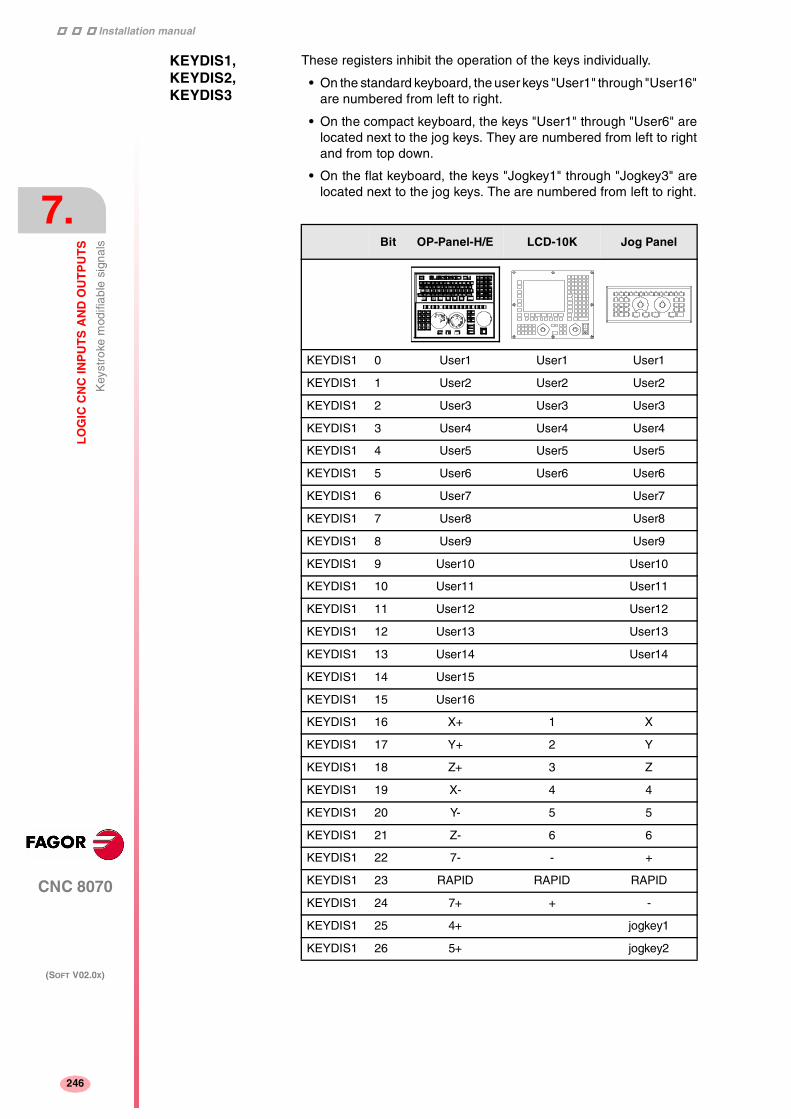
Installation manual
247
CNC 8070
7.
LO
GIC
CN
C IN
PU
TS
AN
D O
UT
PU
TS
Key
stro
ke m
odifi
able
sig
nals
(SOFT V02.0X)
246
KEYDIS1, KEYDIS2, KEYDIS3
These registers inhibit the operation of the keys individually.
• On the standard keyboard, the user keys "User1" through "User16"are numbered from left to right.
• On the compact keyboard, the keys "User1" through "User6" arelocated next to the jog keys. They are numbered from left to rightand from top down.
• On the flat keyboard, the keys "Jogkey1" through "Jogkey3" arelocated next to the jog keys. The are numbered from left to right.
Bit OP-Panel-H/E LCD-10K Jog Panel
KEYDIS1 0 User1 User1 User1
KEYDIS1 1 User2 User2 User2
KEYDIS1 2 User3 User3 User3
KEYDIS1 3 User4 User4 User4
KEYDIS1 4 User5 User5 User5
KEYDIS1 5 User6 User6 User6
KEYDIS1 6 User7 User7
KEYDIS1 7 User8 User8
KEYDIS1 8 User9 User9
KEYDIS1 9 User10 User10
KEYDIS1 10 User11 User11
KEYDIS1 11 User12 User12
KEYDIS1 12 User13 User13
KEYDIS1 13 User14 User14
KEYDIS1 14 User15
KEYDIS1 15 User16
KEYDIS1 16 X+ 1 X
KEYDIS1 17 Y+ 2 Y
KEYDIS1 18 Z+ 3 Z
KEYDIS1 19 X- 4 4
KEYDIS1 20 Y- 5 5
KEYDIS1 21 Z- 6 6
KEYDIS1 22 7- - +
KEYDIS1 23 RAPID RAPID RAPID
KEYDIS1 24 7+ + -
KEYDIS1 25 4+ jogkey1
KEYDIS1 26 5+ jogkey2

Installation manual
CNC 8070
LO
GIC
CN
C IN
PU
TS
AN
D O
UT
PU
TS
Key
stro
ke m
odifi
able
sig
nals
7.
(SOFT V02.0X)
247
The following line inhibits the [X+] key.
( ) = B16 KEYDIS1
When selecting one of the inhibited positions of the feedrate override,the CNC will take the value of the lowest position allowed. If all of themare inhibited, it will take the value of 0%.
For example, being allowed only the 110% and 120% positions, if the50% position is selected, the CNC will take the value of 0%.
KEYDIS1 27 6+ jogkey3
KEYDIS1 28 4-
KEYDIS1 29 5-
KEYDIS1 30 6-
KEYDIS1 31
Bit Key Bit Key
KEYDIS2 0 Spindle Ovr+ 9
KEYDIS2 1 Spindle clockwise 10
KEYDIS2 2 Spindle positioning 11 ZERO
KEYDIS2 3 Spindle stop 12
KEYDIS2 4 Spindle Ovr- 13 Single block
KEYDIS2 5 Spindle c.clockwise 14
KEYDIS2 6 START 15 RESET
KEYDIS2 7 STOP 16-31
KEYDIS2 8
Bit Key Bit Key
KEYDIS3 0 0% 16 140%
KEYDIS3 1 2% 17 150%
KEYDIS3 2 4% 18 160%
KEYDIS3 3 10% 19 170%
KEYDIS3 4 20% 20 180%
KEYDIS3 5 30% 21 190%
KEYDIS3 6 40% 22 200%
KEYDIS3 7 50% 23 Handwheel 100
KEYDIS3 8 60% 24 Handwheel 10
KEYDIS3 9 70% 25 Handwheel 1
KEYDIS3 10 80% 26 JOG 1
KEYDIS3 11 90% 27 JOG 10
KEYDIS3 12 100% 28 JOG 100
KEYDIS3 13 110% 29 JOG 1000
KEYDIS3 14 120% 30 JOG 10000
KEYDIS3 15 130% 31 JOG continuous
Bit OP-Panel-H/E LCD-10K Jog Panel

Installation manual
248
CNC 8070
7.
LO
GIC
CN
C IN
PU
TS
AN
D O
UT
PU
TS
Alp
habe
tical
list
ing
of m
arks
(M
) an
d re
gist
ers
(R)
(SOFT V02.0X)
248
7.13 Alphabetical listing of marks (M) and registers (R)
_ALARM (M).................. Page 207_EMERGEN (M).................. Page 228_FEEDHOL (M).................. Page 229_STOP (M).................. Page 228_XFERINH (M).................. Page 228ADVINPOS (M).................. Page 213AUTOMAT (M).................. Page 207AUXEND (M).................. Page 230AXISNEG(axis) (M).................. Page 233AXISPOS(axis) (M).................. Page 233BLKSEARCH (M).................. Page 212BLKSKIP1 (M).................. Page 231CAXIS (M).................. Page 221CH1TOMZ (M).................. Page 242CH1TOSPDL (M).................. Page 242CH2TOMZ (M).................. Page 243CNCREADY (M).................. Page 206CSS (M).................. Page 209CUTTINGON (M).................. Page 241CYSTART (M).................. Page 229DECEL(axis) (M).................. Page 233DIFFCOMP(axis) (M).................. Page 236DIR(axis) (M).................. Page 215DISCROSS (M).................. Page 232DMxx (M).................. Page 213DRENA(axis) (M).................. Page 235DRO(axis) (M).................. Page 234DRSTAF(axis) (M).................. Page 215DRSTAS(axis) (M).................. Page 215ENABLE(axis) (M).................. Page 215FHOUT (M).................. Page 206FREE (M).................. Page 213GEAR1- GEAR4 (M).................. Page 237GRTOSPDL (M).................. Page 243HFUN (R) .................. Page 210HIRTHON(axis) (M).................. Page 216HSTROBE (M).................. Page 212IABORT(axis) (M).................. Page 240IBUSY(axis) (M).................. Page 222IEND(axis) (M).................. Page 222IFHOUT(axis) (M).................. Page 222IFREE(axis) (M).................. Page 222INCYCLE (M).................. Page 208INHIBIT(axis) (M).................. Page 233INPOS (M).................. Page 209INPOS(axis) (M).................. Page 216INSYNC(axis) (M).................. Page 222INTEREND (M).................. Page 209IRESET(asix) (M).................. Page 240KEYBD1, KEYBD2 (R) .................. Page 225KEYDIS1- KEYDIS3 (R) .................. Page 246KEYLED1, KEYLED2(R).................. Page 245LATCHM (M).................. Page 230LEAVEPOS (R) .................. Page 224LIM(axis)OFF (M).................. Page 235LIMITNEG(axis) (M).................. Page 233LIMITPOS(axis) (M).................. Page 233LUBR(axis) (M).................. Page 216LUBRENA(axis) (M).................. Page 236
LUBROK(axis) (M).................. Page 236M01STOP (M).................. Page 231MANRAPID (M).................. Page 229MANUAL (M).................. Page 207MATCH(axis) (M).................. Page 216MDI (M).................. Page 207MFUN (R) .................. Page 210MMCWDG (M).................. Page 214MSTROBE (M).................. Page 211MZID (R) .................. Page 224MZPOS (R) .................. Page 244MZROT (M).................. Page 244MZTOCH1 (M).................. Page 242MZTOSPDL (M).................. Page 243NEXTPOS (R) .................. Page 224NOWAIT (M).................. Page 232OVRCAN (M).................. Page 230PARK(axis) (M).................. Page 217PARKED(axis) (M).................. Page 235PLCCNTL (M).................. Page 238PLCREADY (M).................. Page 232PROBE (M).................. Page 208RAPID (M).................. Page 208REFPOIN(axis) (M).................. Page 215RESETIN (M).................. Page 230RESETOUT (M).................. Page 206RESTMEM (M).................. Page 241REVOK (M).................. Page 221RIGID (M).................. Page 209SANALOG (R) .................. Page 238SBLOCK (M).................. Page 229SBOUT (M).................. Page 208SERVO(axis)ON (M).................. Page 234SETTMEM (M).................. Page 241SFUN (R) .................. Page 212SPDLEREV (M).................. Page 238SPDLTOCH1 (M).................. Page 242SPDLTOCH2 (M).................. Page 242SPDLTOGR (M).................. Page 243SPDLTOMZ (M).................. Page 243SPENA(axis) (M).................. Page 235SPN (R) .................. Page 211SSTROBE (M).................. Page 212START (M).................. Page 206SYNC (R) .................. Page 214TAKEPOS (R) .................. Page 224TAPPING (M).................. Page 209TCHANGEOK (M).................. Page 244THREAD (M).................. Page 209TIMERON (M).................. Page 231TMINEM (R) .................. Page 224TMOPERATION (M).................. Page 223TMOPSTROBE (M).................. Page 223TREJECT (M).................. Page 241TWORNOUT (M).................. Page 224UNPARK(axis) (M).................. Page 217WAITOUT (M).................. Page 213ZERO (M).................. Page 208

8
249
CNC 8070
(SOFT V02.0X)
TOOL AND MAGAZINE MANAGEMENT
To properly configure the tool magazines and the tool change, youmust:
• Set the machine parameters.
• Set the tool table and the tool magazine table.
• Write the PLC program.
• Program the subroutine associated with the tool and with the M06function
The machine parameters define the number of tool magazinesavailable and their characteristics. Up to four magazines may be usedand each may be of a different type. See "8.1 Types of toolmagazine" on page 252.
When creating the PLC program and the subroutine associated withthe tool and with the M06 function, you must bear in mind the numberof magazines and channels available. For the communicationbetween the tool manager and the PLC, each channel and eachmagazine has its own group of marks and registers.
The PLC maneuver will be different depending on the type of toolmagazine. Later sections of this chapter show an example for eachtype of magazine.
About the magazines.
The CNC can have up to four magazines and each may be of adifferent type. Each magazine has its own configuration parameters.See "2.7 Machine parameters for the magazine" on page 101.
The number of magazines is independent from the number of spindlesand channels available. A magazine is not associated with anyparticular channel or spindle; i.e. a magazine may be shared byseveral channels and a channel can request tools from differentmagazines.
All the magazines can carry out tool changes simultaneously.However, one magazine can only be involved in a tool change process.If from one channel, one wishes to pick up or leave a tool in a magazinealready involved in a tool change, the tool manager will wait for the toolchange to be done before attending to the new request.
Two magazines may be involved in a tool change. The magazinereceiving the tool and the magazine from where the new tool is pickedup may be different.
The access to the magazine depends on the mechanical configurationof the machine; in other words, to the physical possibility of themachine to access the magazines.
i

Installation manual
322
CNC 8070
8.
TO
OL
AN
D M
AG
AZ
INE
MA
NA
GE
ME
NT
(SOFT V02.0X)
250
About the tools
Each tool is identified by its number, that is unique for the wholesystem; it cannot be repeated in different magazines nor in groundtools.
The list of available tools is saved in the tool table, the only one for thewhole system. This table indicates the position and the magazinewhere each tool is located, whether it is a ground tool or the tool isactive in a channel.
The tools are always stored in the same magazine. When doing a toolchange, it is always stored in the magazine from which it was pickedup.
Ground tools
A ground tool is a tool that is not stored in any magazine and is loadedmanually when requested. Ground tools are also defined in the tooltable, but they are not associated with any magazine position.
Ground tool loading and unloading is global to the system; it is notassociated with any particular magazine or channel.
Tool manager
The CNC has a tool magazine management that knows at all timesthe location of each tool. When requesting a tool change or toolsearch, the tool manager "tells" the PLC the operations to be carriedout.
• Take a tool from the magazine and insert it in the spindle.
• Leave the tool of the spindle in the magazine and take another one.
• Leave the spindle tool on the ground.
• Etc.
Depending on the type of magazine and the operation requested,several actions may be needed sometimes. For example, in somemagazines, to take a tool from the spindle to the main magazine, thetool must be carried from the spindle to the changer arm and then fromthe changer arm to the magazine.
It is up to the PLC to control those movements. It must inform themanager about the actions carried out so it updates its information.
For the communication between the tool manager and the PLC, eachchannel and magazine has its own group of marks and registers. See"7.5 Tool manager consulting signals" on page 223. See"7.11 Tool manager modifiable signals" on page 241.

Installation manual
CNC 8070
TO
OL
AN
D M
AG
AZ
INE
MA
NA
GE
ME
NT
8.
(SOFT V02.0X)
251
Subroutines associated with the tool change
There are two subroutines associated with the tool change.
Subroutines associated with the tool.
The subroutine associated with the tool is executed automaticallyevery time a T function (tool selection) is executed.
There is one subroutine in each channel.
Subroutines associated with the M06 function.
The M06 function executes the tool change. The CNC will manage thetool change and update the table for the tool magazine.
It is recommended to set this function in the "M" function table so itexecutes the subroutine for the tool changer installed on the machine.
This subroutine is common to the whole system.
Within both subroutines, the "modal" condition of the canned cyclesno longer has any influence. This characteristic is restored when theexecution of the subroutine ends.
i
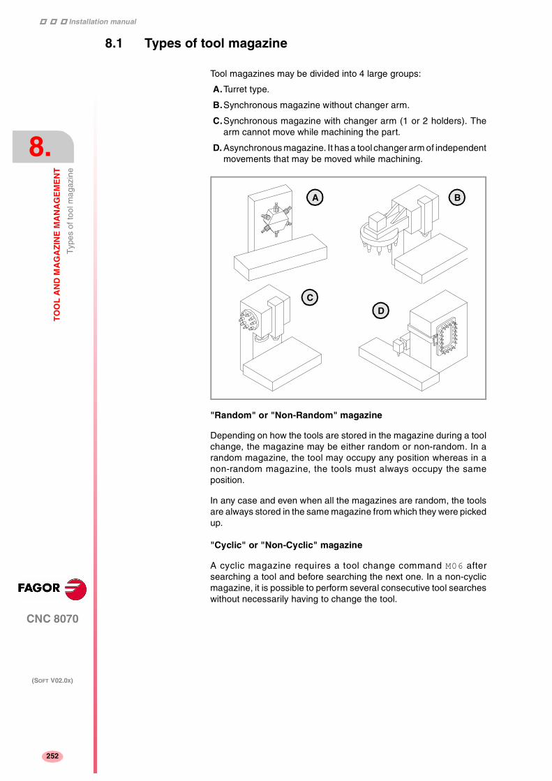
Installation manual
322
CNC 8070
8.
TO
OL
AN
D M
AG
AZ
INE
MA
NA
GE
ME
NT
Typ
es o
f too
l mag
azin
e
(SOFT V02.0X)
252
8.1 Types of tool magazine
Tool magazines may be divided into 4 large groups:
A.Turret type.
B.Synchronous magazine without changer arm.
C.Synchronous magazine with changer arm (1 or 2 holders). Thearm cannot move while machining the part.
D. Asynchronous magazine. It has a tool changer arm of independentmovements that may be moved while machining.
"Random" or "Non-Random" magazine
Depending on how the tools are stored in the magazine during a toolchange, the magazine may be either random or non-random. In arandom magazine, the tool may occupy any position whereas in anon-random magazine, the tools must always occupy the sameposition.
In any case and even when all the magazines are random, the toolsare always stored in the same magazine from which they were pickedup.
"Cyclic" or "Non-Cyclic" magazine
A cyclic magazine requires a tool change command M06 aftersearching a tool and before searching the next one. In a non-cyclicmagazine, it is possible to perform several consecutive tool searcheswithout necessarily having to change the tool.
A
CD
B

Installation manual
CNC 8070
TO
OL
AN
D M
AG
AZ
INE
MA
NA
GE
ME
NT
Too
l tab
le, a
ctiv
e to
ol ta
ble
and
tool
mag
azin
e ta
ble
8.
(SOFT V02.0X)
253
8.2 Tool table, active tool table and tool magazine table
After setting the machine parameters for the tool magazines, definethe tool table and then the magazine table.
Tool table
The tool table must contain, among other things, the geometry, typeof monitoring and tool size. All the tools must be defined, including theground ones.
The tool manager inserts the special tools always in the same toolpocket regardless of the number of pockets they occupy.
Tool magazine table
There is one table for each magazine. Each table shows which toolis in each pocket and on each holder of the changer arm (if any).
Although the magazine table may be initialized manually, it is up to thetool manager to dynamically update all its data.
Active-tools table
The active-tools table shows which tools are active in the spindles.
Example:
Having 10 tools and a 10-position magazine. The tools are small,except T2 that is too large and T4 that has a special size (0 to theleft and 1 to the right).
Load the tools one by one in the magazine using the correspondingsoftkey.
• T1 in position 1.
• T2 in position 3. Verify that it cannot go in position 2 because thetool is too large
• T3 in position 5. T2 occupies positions 2-3-4.
• T4 in position 6. T4 occupies positions 6-7.
• T5 in position 8.
• T6 in position 9.
• T7 in position 10.
T8, T9 and T10 do not fit in the magazine; therefore, they will beground tools.
Installation manual
322
CNC 8070
8.
TO
OL
AN
D M
AG
AZ
INE
MA
NA
GE
ME
NT
Com
mun
icat
ion
betw
een
man
ager
and
PLC
(SOFT V02.0X)
254
8.3 Communication between manager and PLC
For the communication between the tool manager and the PLC, eachchannel and magazine has its own group of marks and registers. See"7.5 Tool manager consulting signals" on page 223. See"7.11 Tool manager modifiable signals" on page 241.
The communication between the manager and the PLC takes placein two stages; when executing the T function and when executing theM06 function.
• When executing the T function, the CNC lets the tool managerknow about it.
The tool manager sends a command to the PLC to select the nexttool in the magazine (if possible).
The CNC continues with the execution of the program withoutwaiting for the tool manager to complete the operation.
• When executing the M06 function, its associated subroutine iscalled upon. The M06 function must also be programmed insidethat subroutine so the CNC "tells" the tool manager to start makingthe tool change.
The tool manager sends a command to the PLC to make thechange.
The CNC waits for the tool manager to complete the operationbefore continuing with the execution of the program.
Considerations and recommendations
The management of the tool change should be included in thesubroutine associated with the M06 and leave the control of theexternal devices up to the PLC.
Use the auxiliary functions to govern the various devices (magazinerotation, magazine movement, tool changer arm, etc.) from the M06subroutine.
On asynchronous magazines (changer arm with independentmovements) when the change implies leaving a tool in the magazine,the TCHANGEOK mark may be activated so the CNC goes on executingthe program while the tool is being taken to the magazine.
The CNC maintains compatibility with the marks and registers ofprevious versions whose mnemonics do not refer to any particularchannel or magazine.
From software version V2.00 on, these signals refer to the first channelor magazine accordingly.
i

Installation manual
CNC 8070
TO
OL
AN
D M
AG
AZ
INE
MA
NA
GE
ME
NT
Com
mun
icat
ion
betw
een
man
ager
and
PLC
8.
(SOFT V02.0X)
255
8.3.1 Manager --> PLC communication
The manager uses the following registers and marks to inform the PLCabout the operations it must carry out. Some signals are per channelwhereas others are per magazine. See "7.5 Tool managerconsulting signals" on page 223.
The following table shows the mnemonics for each mark (M) orregister (R) in each channel or magazine.
TMOPSTROBE The channel tool manager sets this mark high (=1) to let the PLC knowthat it must execute the operation indicated by the TMOPERATIONmark of the channel.
LEAVEPOS This register indicates the magazine position to leave the tool.
TAKEPOS This register indicates the magazine position of the tool to be taken.
NEXTPOS This register indicates the magazine position occupied by the nexttool.
MZID This register indicates which magazine contains the tool requested bythe channel.
When two magazines are involved in a tool change, the lower portionof this register indicates the destination magazine for the tool and thehigher portion the source magazine for the tool.
TMOPERATION This register indicates the type of operation to be carried out by thetool manager.
M/R Channel ·1· Channel ·2· Channel ·3· Channel ·4·
M TMOPSTROBETMOPSTROBEC1 TMOPSTROBEC2 TMOPSTROBEC3 TMOPSTROBEC4
R TMOPERATIONTMOPERATIONC1 TMOPERATIONC2 TMOPERATIONC3 TMOPERATIONC4
R MZIDC1 MZIDC2 MZIDC3 MZIDC4
M/R Magazine ·1· Magazine ·2· Magazine ·3· Magazine ·4·
R LEAVEPOSLEAVEPOSMZ1 LEAVEPOSMZ2 LEAVEPOSMZ3 LEAVEPOSMZ4
R TAKEPOSTAKEPOSMZ1 TAKEPOSMZ2 TAKEPOSMZ3 TAKEPOSMZ4
R NEXTPOSNEXTPOSMZ1 NEXTPOSMZ2 NEXTPOSMZ3 NEXTPOSMZ4
0 Do nothing.
1 Take a tool from the magazine and insert it in the spindle.
2 Leave the spindle tool in the magazine.
3 Insert a ground tool in the spindle.
4 Leave the spindle tool on the ground.
5 Leave the spindle tool in the magazine and take another one fromthe same magazine.

Installation manual
322
CNC 8070
8.
TO
OL
AN
D M
AG
AZ
INE
MA
NA
GE
ME
NT
Com
mun
icat
ion
betw
een
man
ager
and
PLC
(SOFT V02.0X)
256
6 Leave the spindle tool in the magazine and take another one fromground.
7 Leave the spindle tool on the ground and take another one from themagazine.
8 Leave the spindle tool on the ground and take another one fromground.
9 Take a ground tool to the magazine going through the spindle.
10 Take a tool from the magazine and leave on the ground going throughthe spindle.
11 Orient the magazine.
12 Leave the spindle tool in the magazine and take another one fromthe same magazine. Special for a synchronous magazine in thefollowing cases:
• Non-random having a tool changer arm with two claws.
• Random when having special tools.
13 Orienting two magazines.
14 Leave the spindle tool in a magazine and take another one fromanother magazine.

Installation manual
CNC 8070
TO
OL
AN
D M
AG
AZ
INE
MA
NA
GE
ME
NT
Com
mun
icat
ion
betw
een
man
ager
and
PLC
8.
(SOFT V02.0X)
257
8.3.2 PLC --> Manager communication
The PLC uses the following marks to inform the manager about theoperations that it has carried out. There is one group of marks for eachmagazine. See "7.11 Tool manager modifiable signals" on page241.
The PLC, depending on the type of magazine, must take some actionsto execute the operations requested by the manager. After endingeach one of them, it must activate certain marks to inform the managerthat the action has been completed. The manager sets them back to"0" once they are read.
The following table shows the mnemonics for each mark (M) orregister (R) in each channel or magazine.
MZTOCH1 Use it with an asynchronous magazine or synchronous with arm.
The PLC must set this mark high (=1) after taking the tool from themagazine to the changer arm 1.
CH1TOSPDL Use it with an asynchronous magazine or synchronous with arm.
The PLC must set this mark high (=1) after taking the tool from thechanger arm 1 to the spindle.
M/R Magazine ·1· Magazine ·2· Magazine ·3· Magazine ·4·
M MZTOCH1MZTOCH1MZ1 MZTOCH1MZ2 MZTOCH1MZ3 MZTOCH1MZ4
M CH1TOSPDLCH1TOSPDLMZ1 CH1TOSPDLZ2 CH1TOSPDLMZ3 CH1TOSPDLMZ4
M SPDLTOCH1SPDLTOCH1MZ1 SPDLTOCH1MZ2 SPDLTOCH1MZ3 SPDLTOCH1MZ4
M SPDLTOCH2SPDLTOCH2MZ1 SPDLTOCH2MZ2 SPDLTOCH2MZ3 SPDLTOCH2MZ4
M CH1TOMZCH1TOMZ1 CH1TOMZ2 CH1TOMZ3 CH1TOMZ4
M CH2TOMZCH2TOMZ1 CH2TOMZ2 CH2TOMZ3 CH2TOMZ4
M SPDLTOGRSPDLTOGRMZ1 SPDLTOGRMZ2 SPDLTOGRMZ3 SPDLTOGRMZ4
M GRTOSPDLGRTOSPDLMZ1 GRTOSPDLMZ2 GRTOSPDLMZ3 GRTOSPDLMZ4
M MZTOSPDLMZTOSPDLMZ1 MZTOSPDLMZ2 MZTOSPDLMZ3 MZTOSPDLMZ4
M MZTOSPDLMZTOSPDLMZ1 MZTOSPDLMZ2 MZTOSPDLMZ3 MZTOSPDLMZ4
M MZROTMZROTMZ1 MZROTMZ2 MZROTMZ3 MZROTMZ4
M TCHANGEOKTCHANGEOKMZ1 TCHANGEOKMZ2 TCHANGEOKMZ3 TCHANGEOKMZ4
R MZPOSMZPOSMZ1 MZPOSZ2 MZPOSMZ3 MZPOSMZ4

Installation manual
322
CNC 8070
8.
TO
OL
AN
D M
AG
AZ
INE
MA
NA
GE
ME
NT
Com
mun
icat
ion
betw
een
man
ager
and
PLC
(SOFT V02.0X)
258
SPDLTOCH1 Use it with an asynchronous magazine with one changer arm.
The PLC must set this mark high (=1) after taking the tool from thespindle to the changer arm 1.
SPDLTOCH2 Use it with an asynchronous magazine or synchronous with arm.
The PLC must set this mark high (=1) after taking the tool from thespindle to the changer arm 2.
CH1TOMZ Use it with an asynchronous magazine or synchronous with arm.
The PLC must set this mark high (=1) after taking the tool from the toolchanger arm 1 to the magazine.
CH2TOMZ Use it with an asynchronous magazine or synchronous with arm.
The PLC must set this mark high (=1) after taking the tool from the toolchanger arm 2 to the magazine.
SPDLTOGR Use it with a magazine that admits ground tools.
The PLC must set this mark high (=1) after taking the tool from thespindle to ground.
GRTOSPDL Use it with a magazine that admits ground tools.
The PLC must set this mark high (=1) after taking the tool from theground to the spindle.
MZTOSPDL Use it with a synchronous magazine (without arm).
The PLC must set this mark high (=1) after taking the tool from themagazine to the spindle.
SPDLTOMZ Use it with a synchronous magazine (without arm).
The PLC must set this mark high (=1) after taking the tool from thespindle to the magazine.
MZROT Use it with a turret-type magazine and with a synchronous magazine.
The PLC must set this mark high (=1) when the turret has rotated. Inthe synchronous magazine, it is used to optimize the change byorienting the magazine while machining. The PLC must set this markto (=1) to indicate that the operation has been completed, whether ithas been oriented or not.
TCHANGEOK On asynchronous magazines (with changer arm of independentmovements) the following mark may be activated so the CNC goes onexecuting the program while the tool is being taken to the magazine.
The PLC must set this mark high (=1) to "tell" the manager to go onexecuting the program while the tool is being taken to the magazine.
MZPOS On random magazines, magazine orientations may be optimized if themanager knows the position selected at all times.
The PLC must indicate the current magazine position in this register.When not using this register, the PLC must set it to "0".

Installation manual
CNC 8070
TO
OL
AN
D M
AG
AZ
INE
MA
NA
GE
ME
NT
Com
mun
icat
ion
betw
een
man
ager
and
PLC
8.
(SOFT V02.0X)
259
8.3.3 Manager Emergency
The manager may be set in an Emergency state when a malfunctionoccurs (the PLC has executed the wrong action, incomplete toolchange, etc.) or if the PLC activates the emergency.
The PLC marks related to manager emergency are the following:There is one group of marks for each magazine.
The following table shows the mnemonics for each mark (M) in eachchannel or magazine.
SETTMEM The PLC sets this mark high (=1) to activate the tool manageremergency.
RESTMEM The PLC sets this mark high (=1) to cancel the tool manageremergency.
TMINEM The CNC sets this mark high (=1) to inform the PLC that an emergencyhas occurred at the tool manager.
To generate an emergency at the manager from the PLC:
1. Activate the emergency.
DFU (error condition) = SET SETTMEM
2. Make sure that the emergency has occurred before canceling it.
TMINEM AND DFU (removal condition) = SET RESTMEM
The manager sets the SETMEM and RESTMEM signals low (=0).
M/R Magazine ·1· Magazine ·2· Magazine ·3· Magazine ·4·
M SETTMEMSETTMEMZ1 SETTMEMZ2 SETTMEMZ3 SETTMEMZ4
M RESTMEMRESTMEMZ1 RESTMEMZ2 RESTMEMZ3 RESTMEMZ4
M TMINEMTMINEMZ1 TMINEMZ2 TMINEMZ3 TMINEMZ4

Installation manual
322
CNC 8070
8.
TO
OL
AN
D M
AG
AZ
INE
MA
NA
GE
ME
NT
Com
mun
icat
ion
betw
een
man
ager
and
PLC
(SOFT V02.0X)
260
8.3.4 Tool monitoring
The PLC marks related to tool monitoring are the following. There isone group of marks for each channel.
The following table shows the mnemonics for each mark (M) in eachchannel or magazine.
The PLC marks related to tool monitoring are:
CUTTINGON When a tool is assigned a maximum life span (monitoring), the CNCchecks this mark in order to know whether the tool is machining (=1)or not (=0).
It is usually considered to be machining when the following conditionsare met:
• The spindle is turning (M3 or M4) or when the tool is threadcuttingand the 0% of feedrate is not selected.
• The automatic operating mode is selected, there is a block inexecution and the G00 function is not active.
• The execution is not interrupted.
TREJECT If the PLC sets this mark high (=1), the CNC interprets that the toolmust be rejected.
TWORNOUT The CNC sets this mark high (=1) to "tell" the PLC that the tool hasbeen rejected because it is worn out (real life > maximum life span).
M/R Channel ·1· Channel ·2· Channel ·3· Channel ·4·
M CUTTINGONCUTTINGONC1 CUTTINGONC2 CUTTINGONC3 CUTTINGONC4
M TREJECTTREJECTC1 TREJECTC2 TREJECTC3 TREJECTC4
M TWORNOUTTWORNOUTC1 TWORNOUTC2 TWORNOUTC3 TWORNOUTC4

Installation manual
CNC 8070
TO
OL
AN
D M
AG
AZ
INE
MA
NA
GE
ME
NT
Var
iabl
es r
elat
ed to
tool
mag
azin
e m
anag
emen
t
8.
(SOFT V02.0X)
261
8.4 Variables related to tool magazine management
The variables associated with the magazine that are involved in thetool magazine management are the following. There is one group ofvariables for each channel. Replace the [n] character with the channelnumber, maintaining the brackets.
V.[n].TM.MZMODE Operating mode of the tool magazine manager.
0 Normal mode (by default and after Reset).
1 Magazine loading mode.
2 Magazine unloading mode.
V.[n].TM.MZSTATUS Tool manager status.
0 Normal operation.
1 An error has occurred.
2 An error has occurred; but it will wait for the currentmaneuver to be completed.
4 Emergency.
V.[n].TM.MZRUN Tool manager running.
0 There is no sequence in execution.
1 There is a sequence in execution.
V.[n].TM.MZWAIT Tool manager executing a maneuver. It indicates whether to wait ornot for the maneuver to end.
0 No need to wait.
1 It has to wait.
There is no need to program it in the subroutine associated with M06.The subroutine itself waits for the manager's maneuvers to finish. Thisway, block preparation is not interrupted.
Installation manual
322
CNC 8070
8.
TO
OL
AN
D M
AG
AZ
INE
MA
NA
GE
ME
NT
Too
l loa
ding
and
unl
oadi
ng fr
om th
e m
agaz
ines
(SOFT V02.0X)
262
8.5 Tool loading and unloading from the magazines
Tool loading and unloading from the magazine
Each magazine table has softkeys for initializing, loading andunloading tools in the magazine either manually or automatically.Refer to the operation manual.
The tools may also be loaded and unloaded in the magazine byprogram or in MDI mode.
Tool loading and unloading from the spindle
The tools must always be loaded and unloaded in the spindle and onthe changer arm in manual mode from the magazine table. Refer tothe operation manual.
Loading the magazine by program or in MDI mode
The tools are loaded in the magazine by taking them one by one fromground to the magazine going through the spindle.
Set the variable: V.TM.MZMODE=1 to "tell" the tool manager that themagazine loading mode has be chosen.
If a T1 M6 is executed next, the tool manager interprets that T1 mustbe taken from ground to the magazine going through the spindle andit will let the PLC know by setting TMOPERATION=9.
The subroutine associated with the M06 function and the PLC programmust contain the maneuver needed to make the tool change.
After loading the tool, the tool manager updates the magazine table.
Unloading the magazine by program or MDI
The tools are unloaded from the magazine taking them one by onefrom the magazine to the ground going through the spindle.
Set variable: V.TM.MZMODE=2 to "tell" the tool manager that themagazine unloading mode has been chosen.
If a T1 M6 is executed next, the tool manager interprets that T1 mustbe taken from the magazine to ground going through the spindle andit will let the PLC know by setting TMOPERATION=10.
The subroutine associated with the M06 function and the PLC programmust contain the maneuver needed to make the tool change.
After unloading the tool, the tool manager updates the magazine table.

Installation manual
CNC 8070
TO
OL
AN
D M
AG
AZ
INE
MA
NA
GE
ME
NT
Too
l loa
ding
and
unl
oadi
ng fr
om th
e m
agaz
ines
8.
(SOFT V02.0X)
263
Placing a tool in the spindle by program or in MDI mode
Set variable: V.TM.MZMODE=0 to "tell" the tool manager that thenormal mode has been chosen.
If T1 M6 is executed next, the tool manager checks whether there isalready a tool in the spindle (to remove it first) and whether therequested tool is in the magazine or it has to be picked up from theground. In any case, it lets the PLC know which operation it must carryout by setting TMOPERATION to the proper value.
The subroutine associated with the M06 function and the PLC programmust contain the maneuver needed to make the tool change.
After placing the tool, the tool manager updates the magazine table.

Installation manual
322
CNC 8070
8.
TO
OL
AN
D M
AG
AZ
INE
MA
NA
GE
ME
NT
Tur
ret t
ype
(SOFT V02.0X)
264
8.6 Turret type
When selecting a tool, the subroutine associated with the T executesthe M06 function (tool change), machining stops and the tool managersends to the PLC the code for the operation to be carried out.
The management of the tool change should be included in thesubroutine associated with the M06 and leave the control of theexternal devices up to the PLC.
This type of magazine does not admit ground tools when it is in normalmode; but it does when the magazine is in load/download mode.
T0 cannot be programmed for this type of magazine.

Installation manual
CNC 8070
TO
OL
AN
D M
AG
AZ
INE
MA
NA
GE
ME
NT
Tur
ret t
ype
8.
(SOFT V02.0X)
265
8.6.1 Values of the TMOPERATION and marks to be activated by the PLC
The possible TMOPERATION values in this type of magazine and theassociated marks and registers are the following:
TMOPERATION=1 Assume the tool as active tool.
TAKEPOS Indicates the position of the tool to be picked up.
When the operation is completed, activate the mark MZTOSPDL.
TMOPERATION=11 Orient the turret.
When the operation is completed, activate the mark MZROT.
Summary
The values sent by the tool manager to the PLC in each operation andthe marks to be activated by the PLC are the following:
The TAKEPOS and LEAVEPOS values indicate the following:
0 Do nothing.
# Magazine position number.
-4 Ground position.
Application example
It shows the functions executed by the CNC, the values sent by thetool manager to the PLC in each operation and the marks to beactivated by the PLC in each case.
TM ==> PLCPLC ==> TM
TMOPERATION TAKEPOS LEAVEPOS
1 # 0 MZTOSPDL
11 0 0 MZROT
CNCTM ==> PLC
PLC ==> TMTMOPERATION TAKEPOS LEAVEPOS
T1M6
111
01
00
MZROTMZTOSPDL
T2M6
111
01
00
MZROTMZTOSPDL

Installation manual
322
CNC 8070
8.
TO
OL
AN
D M
AG
AZ
INE
MA
NA
GE
ME
NT
Tur
ret t
ype
(SOFT V02.0X)
266
8.6.2 Communication between the PLC and the M06 subroutine
The communication between the PLC and the M06 subroutine takesplace using a series of generic marks and registers. The program ofthe M06 subroutine offered as an example uses the following marksand registers.
Communication between the PLC and the M06 subroutine
Registers used by the PLC to transfer information to the M06subroutine:
Communication between the PLC and the M06 subroutine
Marks activated by the M06 subroutine so the PLC activates therelevant mark of the tool manager.
M functions at the PLC
M functions that imply movements controlled by the PLC:
Set the M function with "before-before" synchronization so theprogram continues after the M function is completed.
R101 Type of operation requested by the tool manager (value ofTMOPERATION).
M1111 MZROT
The magazine has rotated already.
M111 Select at the magazine the pocket indicated by TAKEPOS.

Installation manual
CNC 8070
TO
OL
AN
D M
AG
AZ
INE
MA
NA
GE
ME
NT
Tur
ret t
ype
8.
(SOFT V02.0X)
267
8.6.3 Program of the M06 subroutine
%L SUB_MZ_ROTM111
Auxiliary function to execute an action.
V.PLC.M[1111]=1
MZROT mark to the tool manager.
#RET
%SUB_M6.ncM6
Order the tool manager to start the tool change.
$IF V.PLC.R[101] == 1LL SUB_MZ_ROT
$ENDIF
If type of operation=1, execute the subroutine.
$WHILE V.TM.MZWAIT == 1$ENDWHILE
Wait for the tool manager.
#RET
End of M06 subroutine.

Installation manual
322
CNC 8070
8.
TO
OL
AN
D M
AG
AZ
INE
MA
NA
GE
ME
NT
Tur
ret t
ype
(SOFT V02.0X)
268
8.6.4 Basic PLC programming
When executing the M06 function
When executing the M06 function, the tool manager sends to the PLC,in the TMOPERATION register, the code for the operation to be carriedout.
DFU TMOPSTROBE = MOV TMOPERATION R101
This instruction transfers the TMOPERATION value to register R101 soit is managed by the M06 subroutine.
Every time the M06 subroutine ends the action, it lets the PLC knowso it activates the relevant mark of the tool manager.
DFU M1111 = SET MZROT
DFD MZROT = RES M1111
The magazine has rotated already.
Define the auxiliary function M111 to select the magazine positionindicated by TAKEPOS. The auxiliary function will conclude afterexecuting the requested movement.
Manager emergency signal
Treatment of the tool manager emergency signal.
DFU B11KEYBD1 = SET SETTMEM
Pressing the USER12 key activates the emergency.
TMINEM = B11KEYLED1
The lamp of the USER12 key turns on when there is an emergency.
TMINEM AND DFU B12KEYBD1 = SET RESTMEM
Pressing the USER13 key removes the emergency.

Installation manual
CNC 8070
TO
OL
AN
D M
AG
AZ
INE
MA
NA
GE
ME
NT
Syn
chro
nous
mag
azin
e w
ithou
t cha
nger
arm
8.
(SOFT V02.0X)
269
8.7 Synchronous magazine without changer arm
The communication between the tool manager and the PLC takesplace in two stages.
• When executing the T function, the CNC lets the tool managerknow about it.
The tool manager sends a command to the PLC to select the nexttool in the magazine (if possible).
The CNC continues with the execution of the program withoutwaiting for the tool manager to complete the operation.
• When executing the M06 function, its associated subroutine iscalled upon.
The M06 function must also be programmed inside that subroutineso the CNC "tells" the tool manager to start making the tool change.
The tool manager sends a command to the PLC to make thechange.
The CNC waits for the tool manager to complete the operationbefore continuing with the execution of the program.
The management of the tool change should be included in thesubroutine associated with the M06 and leave the control of theexternal devices up to the PLC.
Use the auxiliary functions to govern the various devices (magazinerotation, magazine movement, tool changer arm, etc.) from the M06subroutine.

Installation manual
322
CNC 8070
8.
TO
OL
AN
D M
AG
AZ
INE
MA
NA
GE
ME
NT
Syn
chro
nous
mag
azin
e w
ithou
t cha
nger
arm
(SOFT V02.0X)
270
8.7.1 Values of the TMOPERATION and marks to be activated by the PLC
The possible TMOPERATION values in this type of magazine and themarks and registers associated with each case are:
TMOPERATION=1 Take a tool from the magazine and insert it in the spindle.
TAKEPOS Position occupied by the tool.
When the operation is completed, activate the mark MZTOSPDL.
TMOPERATION=2 Leave the spindle tool in the magazine.
LEAVEPOS Position to leave the tool.
When the operation is completed, activate the mark SPDLTOMZ.
TMOPERATION=3 Insert a ground tool in the spindle.
TAKEPOS=-4 Pick up the ground tool.
When the operation is completed, activate the mark GRTOSPDL.
TMOPERATION=4 Leave the spindle tool on the ground.
LEAVEPOS=-4 Leave the tool on the ground.
When the operation is completed, activate the mark SPDLTOGR.
TMOPERATION=5 Leave the spindle tool in the magazine and take another one from themagazine.
TAKEPOS Position occupied by the tool.
LEAVEPOS Position to leave the tool.
1. Leave the tool of the spindle in the magazine and activate the markSPDLTOMZ.
2. Leave the tool of the magazine in the spindle and activate the markMZTOSPDL.
TMOPERATION=6 Leave the spindle tool in the magazine and take another one fromground.
TAKEPOS=-4 Pick up the ground tool.
LEAVEPOS Position to leave the tool.
1. Leave the tool of the spindle in the magazine and activate the markSPDLTOMZ.
2. Leave the ground tool in the spindle and activate the markGRTOSPDL.
TMOPERATION=7 Leave the spindle tool on the ground and take another one from themagazine.
TAKEPOS Position occupied by the tool.
LEAVEPOS=-4 Leave the tool on the ground.
1. Leave the tool of the spindle on the ground and activate the markSPDLTOGR.
2. Leave the tool of the magazine in the spindle and activate the markMZTOSPDL.

Installation manual
CNC 8070
TO
OL
AN
D M
AG
AZ
INE
MA
NA
GE
ME
NT
Syn
chro
nous
mag
azin
e w
ithou
t cha
nger
arm
8.
(SOFT V02.0X)
271
TMOPERATION=8 Leave the spindle tool on the ground and take another one fromground.
TAKEPOS=-4 Pick up the ground tool.
LEAVEPOS=-4 Leave the tool on the ground.
1. Leave the tool of the spindle on the ground and activate the markSPDLTOGR.
2. Leave the ground tool in the spindle and activate the markGRTOSPDL.
TMOPERATION=9 Take a ground tool to the magazine going through the spindle.
TAKEPOS=-4 Pick up the ground tool.
LEAVEPOS Position to leave the tool.
1. Leave the ground tool in the spindle and activate the markGRTOSPDL.
2. Leave the tool of the spindle in the magazine and activate the markSPDLTOMZ.
TMOPERATION=10 Take a tool from the magazine and leave on the ground going throughthe spindle.
TAKEPOS Position occupied by the tool.
LEAVEPOS=-4 Leave the tool on the ground.
1. Leave the tool of the magazine in the spindle and activate the markMZTOSPDL.
2. Leave the tool of the spindle on the ground and activate the markSPDLTOGR.
TMOPERATION=11 In general, it is an optimization of the change that permits orientingthe magazine while machining.
Activate the MZROT mark to indicate that the operation has beencompleted, whether it has been oriented or not.
TMOPERATION=12 Same as TMOPERATION=5. Only for random magazines and whenhaving special tools.
TMOPERATION=13 In general, it is an optimization of the change that permits orientingtwo magazines while machining.
Activate the MZROT mark in both magazines to indicate that theoperation has been completed, whether it has been oriented or not.
NEXTPOS Position to leave the tool.
TAKEPOS Position of the tool to be picked up.
MZID Destination magazine to leave the tool and sourcemagazine from which to pick up the new one.
TMOPERATION=14 Leave the spindle tool in a magazine and take a tool from anothermagazine.
TAKEPOS Position of the tool to be picked up.
LEAVEPOS Position to leave the tool.
MZID Destination magazine to leave the tool and sourcemagazine from which to pick up the new one.
1. Leave the tool of the spindle in the magazine and activate the markSPDLTOMZ.
2. Leave the tool of the magazine in the spindle and activate the markMZTOSPDL.

Installation manual
322
CNC 8070
8.
TO
OL
AN
D M
AG
AZ
INE
MA
NA
GE
ME
NT
Syn
chro
nous
mag
azin
e w
ithou
t cha
nger
arm
(SOFT V02.0X)
272
Summary
The values sent by the tool manager to the PLC in each operation andthe marks to be activated by the PLC are the following:
The TAKEPOS and LEAVEPOS values indicate the following:
0 Do nothing.
# Magazine position number.
-4 Ground position.
Application example
Assuming that there is no tool in the spindle, it shows the functionsexecuted by the CNC, the values sent by the tool manager to the PLCin each operation and the marks to be activated by the PLC in eachcase.
It is a non-random magazine, each tool occupies the position of its ownnumber and TG7, TG8 and TG9 are ground tools.
TM ==> PLCPLC ==> TM
TMOPERATION TAKEPOS LEAVEPOS
1 # 0 MZTOSPDL
2 0 # SPDLTOMZ
3 -4 0 GRTOSPDL
4 0 -4 SPDLTOGR
5 # # SPDLTOMZ + MZTOSPDL
6 -4 # SPDLTOMZ + GRTOSPDL
7 # -4 SPDLTOGR + MZTOSPDL
8 -4 -4 SPDLTOGR + GRTOSPDL
9 -4 # GRTOSPDL + SPDLTOMZ
10 # -4 MZTOSPDL + SPDLTOGR
11 0 0 MZROT
12 # # SPDLTOMZ + MZTOSPDL
13 0 0 MZROT + MZROT
14 0 # SPDLTOMZ + MZTOSPDL
CNCTM ==> PLC
PLC ==> TMTMOPERATION TAKEPOS LEAVEPOS
T1M6
111
01
00
MZROTMZTOSPDL
T2M6
115
02
01
MZROTSPDLTOMZ + MZTOSPDL
TG7M6
116
0-4
02
MZROTSPDLTOMZ + GRTOSPDL
TG8M6
118
0-4
0-4
MZROTSPDLTOGR + GRTOSPDL
T3T4M6
11117
004
00-4
MZROTMZROT
SPDLTOGR + MZTOSPDL
T0M6
112
00
04
MZROTSPDLTOMZ
TG9M6
113
0-4
00
MZROTGRTOSPDL
T0M6
114
00
0-4
MZROTSPDLTOGR

Installation manual
CNC 8070
TO
OL
AN
D M
AG
AZ
INE
MA
NA
GE
ME
NT
Syn
chro
nous
mag
azin
e w
ithou
t cha
nger
arm
8.
(SOFT V02.0X)
273
8.7.2 Communication between the PLC and the M06 subroutine
The communication between the PLC and the M06 subroutine takesplace using a series of generic marks and registers. The program ofthe M06 subroutine offered as an example uses the following marksand registers.
Communication between the PLC and the M06 subroutine
Registers used by the PLC to transfer information to the M06subroutine:
Communication between the PLC and the M06 subroutine
Marks activated by the M06 subroutine so the PLC activates therelevant mark of the tool manager.
M functions at the PLC
M functions that imply movements controlled by the PLC:
Set all the M functions with "before-before" synchronization to theprogram continues after the M function is completed.
R101 Type of operation requested by the tool manager (value ofTMOPERATION).
M1107 SPDLTOGR
The tool has been taken from the spindle to ground.
M1108 GRTOSPDL
The tool has been taken from ground to the spindle.
M1109 MZTOSPDL
The tool has been taken from the magazine to the spindle.
M1110 SPDLTOMZ
The tool has been taken from the spindle to the magazine.
M109 Select in the magazine the position indicated by TAKEPOSand insert the tool in the spindle.
M110 Select in the magazine the posit ion indicated byLEAVEPOS and leave the spindle tool.

Installation manual
322
CNC 8070
8.
TO
OL
AN
D M
AG
AZ
INE
MA
NA
GE
ME
NT
Syn
chro
nous
mag
azin
e w
ithou
t cha
nger
arm
(SOFT V02.0X)
274
8.7.3 Program of the M06 subroutine
%L SUB_SPD_TO_GR
Remove the tool from the spindle (take it to ground).
It shows the message for the operator to extract the tool and waits forthe operation to be completed before removing the message.
#MSG ["Extract Tool. T%D and press cycle-start", V.TM.TOOL]M0
#MSG [""]V.PLC.M[1107]=1
SPDLTOGR mark to the tool manager.
#RET
%L SUB_GR_TO_SPD
Insert the ground tool in the spindle.
It shows the message for the operator to insert the tool and waits forthe operation to be completed before removing the message.
#MSG ["Insert Tool. T%D and press cycle-start", V.TM.NXTOOL]
M0#MSG [""]V.PLC.M[1108]=1
GRTOSPDL mark to the tool manager.
#RET
%L SUB_MZ_TO_SPD
Take the tool from the magazine and insert it in the spindle.
M109
Auxiliary function to execute an action.
V.PLC.M[1109]=1
MZTOSPDL mark to the tool manager.
#RET
%L SUB_SPD_TO_MZ
Leave the spindle tool in the magazine.
M110
Auxiliary function to execute an action.
V.PLC.M[1110]=1
SPDLTOMZ mark to the tool manager.
#RET
%L SUB_SPD_GMCHG
Move the spindle to the manual tool change point.
G1 Z_ F_
Move the spindle.
#RET
%L SUB_SPD_AUTCHG
Move the spindle to the automatic tool change point
G1 Z_ F_
Move the spindle.
#RET

Installation manual
CNC 8070
TO
OL
AN
D M
AG
AZ
INE
MA
NA
GE
ME
NT
Syn
chro
nous
mag
azin
e w
ithou
t cha
nger
arm
8.
(SOFT V02.0X)
275
%SUB_M6.ncM6
Order the tool manager to start the tool change.
$SWITCH V.PLC.R[101]
It analyzes the type of operation.
$CASE 1
Take a tool from the magazine and insert it in the spindle.
LL SUB_SPD_AUTCHG
Move the spindle to the automatic tool change point
LL SUB_MZ_TO_SPD
Take the tool from the magazine to the spindle.
$BREAK
$CASE 2
Leave the spindle tool in the magazine.
LL SUB_SPD_AUTCHG
Move the spindle to the automatic tool change point
LL SUB_SPD_TO_MZ
Leave the spindle tool in the magazine.
$BREAK
$CASE 3
Insert the ground tool in the spindle.
LL SUB_SPD_GMCHG
Move the spindle to the manual tool change point.
LL SUB_GR_TO_SPD
Insert the ground tool in the spindle.
$BREAK
$CASE 4
Leave the spindle tool on the ground.
LL SUB_SPD_GMCHG
Move the spindle to the manual tool change point.
LL SUB_SPD_TO_GR
Remove the tool from the spindle.
$BREAK
$CASE 5
Leave the spindle tool in the magazine and take another one from themagazine.
LL SUB_SPD_AUTCHG
Move the spindle to the automatic tool change point
LL SUB_SPD_TO_MZ
Leave the spindle tool in the magazine.
LL SUB_MZ_TO_SPD
Take the tool from the magazine to the spindle.
$BREAK

Installation manual
322
CNC 8070
8.
TO
OL
AN
D M
AG
AZ
INE
MA
NA
GE
ME
NT
Syn
chro
nous
mag
azin
e w
ithou
t cha
nger
arm
(SOFT V02.0X)
276
$CASE 6
Leave the spindle tool in the magazine and take another one fromground.
LL SUB_SPD_AUTCHG
Move the spindle to the automatic tool change point
LL SUB_SPD_TO_MZ
Leave the spindle tool in the magazine.
LL SUB_SPD_GMCHG
Move the spindle to the manual tool change point.
LL SUB_GR_TO_SPD
Insert the ground tool in the spindle.
$BREAK
$CASE 7
Leave the spindle tool on the ground and take another one from themagazine.
LL SUB_SPD_GMCHG
Move the spindle to the manual tool change point.
LL SUB_SPD_TO_GR
Remove the tool from the spindle.
LL SUB_SPD_AUTCHG
Move the spindle to the automatic tool change point
LL SUB_MZ_TO_SPD
Take the tool from the magazine to the spindle.
$BREAK
$CASE 8
Leave the spindle tool on the ground and take another one fromground.
LL SUB_SPD_GMCHG
Move the spindle to the manual tool change point.
LL SUB_SPD_TO_GR
Remove the tool from the spindle.
LL SUB_GR_TO_SPD
Insert the ground tool in the spindle.
$BREAK
$CASE 9
Take a ground tool to the magazine going through the spindle.
LL SUB_SPD_GMCHG
Move the spindle to the manual tool change point.
LL SUB_GR_TO_SPD
Insert the ground tool in the spindle.
LL SUB_SPD_AUTCHG
Move the spindle to the automatic tool change point
LL SUB_SPD_TO_MZ
Leave the spindle tool in the magazine.
$BREAK

Installation manual
CNC 8070
TO
OL
AN
D M
AG
AZ
INE
MA
NA
GE
ME
NT
Syn
chro
nous
mag
azin
e w
ithou
t cha
nger
arm
8.
(SOFT V02.0X)
277
$CASE 10
Take a tool from the magazine and leave on the ground going throughthe spindle.
LL SUB_SPD_AUTCHG
Move the spindle to the automatic tool change point
LL SUB_MZ_TO_SPD
Take the tool from the magazine to the spindle.
LL SUB_SPD_GMCHG
Move the spindle to the manual tool change point.
LL SUB_SPD_TO_GR
Remove the tool from the spindle.
$BREAK
$ENDSWITCH
End of analysis of type of operation.
$WHILE V.TM.MZWAIT == 1$ENDWHILE
Wait for the tool manager.
#RET
End of M06 subroutine.

Installation manual
322
CNC 8070
8.
TO
OL
AN
D M
AG
AZ
INE
MA
NA
GE
ME
NT
Syn
chro
nous
mag
azin
e w
ithou
t cha
nger
arm
(SOFT V02.0X)
278
8.7.4 Basic PLC programming
When executing the -T- function
When executing a T function, the tool manager sends the codeTMOPERATION=11 to the PLC. In general, it is an optimization of thechange that permits orienting the magazine while machining.
In this case, the magazine is not oriented and the MZROT mark isactivated to indicate that the operation has been completed.
DFU TMOPSTROBE AND CPS TMOPERATION EQ 11 = SET MZROT
Activate the MZROT mark to "tell" the tool manager that the operationhas finished.
When executing the M06 function
When executing the M06 function, the tool manager sends to the PLC,in the TMOPERATION register, the code for the operation to be carriedout.
DFU TMOPSTROBE = MOV TMOPERATION R101
This instruction transfers the TMOPERATION value to register R101 soit is managed by the M06 subroutine.
Every time the M06 subroutine ends an action, it lets the PLC knowso it activates the relevant mark of the tool manager.
DFU M1107 = SET SPDLTOGR
DFD SPDLTOGR = RES M1107
The tool has been taken from the spindle to ground.
DFU M1108 = SET GRTOSPDL
DFD GRTOSPDL = RES M1108
The tool has been taken from ground to the spindle.
DFU M1109 = SET MZTOSPDL
DFD MZTOSPDL = RES M1109
The tool has been taken from the magazine to the spindle.
DFU M1110 = SET SPDLTOMZ
DFD SPDLTOMZ = RES M1110
The tool has been taken from the spindle to the magazine.
DFU M1111 = SET MZROT
DFD MZROT = RES M1111
The magazine has rotated already.
The M06 subroutine uses the following M functions to "tell" the PLCwhich movements it must carry out.
Programming it depends on the type of machine. The auxiliaryfunction will conclude after executing the requested movement.
M109 Select in the magazine the position indicated by TAKEPOSand insert the tool in the spindle.
M110 Select in the magazine the posit ion indicated byLEAVEPOS and leave the spindle tool.

Installation manual
CNC 8070
TO
OL
AN
D M
AG
AZ
INE
MA
NA
GE
ME
NT
Syn
chro
nous
mag
azin
e w
ithou
t cha
nger
arm
8.
(SOFT V02.0X)
279
Certain operations require using the information transferred by thetool manager in the following registers:
LEAVEPOS This register indicates the magazine position to leave thetool.
TAKEPOS This register indicates the magazine position of the toolto be taken (picked up).
Manager emergency signal
Treatment of the tool manager emergency signal.
DFU B11KEYBD1 = SET SETTMEM
Pressing the USER12 key activates the emergency.
TMINEM = B11KEYLED1
The lamp of the USER12 key turns on when there is an emergency.
TMINEM AND DFU B12KEYBD1 = SET RESTMEM
Pressing the USER13 key removes the emergency.

Installation manual
322
CNC 8070
8.
TO
OL
AN
D M
AG
AZ
INE
MA
NA
GE
ME
NT
Syn
chro
nous
mag
azin
e. C
hang
er a
rm w
ith in
depe
nden
tm
ovem
ents
.
(SOFT V02.0X)
280
8.8 Synchronous magazine. Changer arm with independentmovements.
Usually the movements of the changer arm depend on machiningbecause it cannot move while the part is being machined.
The communication between the tool manager and the PLC takesplace in two stages.
• When executing the T function, the CNC lets the tool managerknow about it.
The tool manager sends a command to the PLC to select the nexttool in the magazine (if possible).
The CNC continues with the execution of the program withoutwaiting for the tool manager to complete the operation.
• When executing the M06 function, its associated subroutine iscalled upon.
The M06 function must also be programmed inside that subroutineso the CNC "tells" the tool manager to start making the tool change.
The tool manager sends a command to the PLC to make thechange.
The CNC waits for the tool manager to complete the operationbefore continuing with the execution of the program.
The management of the tool change should be included in thesubroutine associated with the M06 and leave the control of theexternal devices up to the PLC.
Use the auxiliary functions to govern the various devices (magazinerotation, magazine movement, tool changer arm, etc.) from the M06subroutine.

Installation manual
CNC 8070
TO
OL
AN
D M
AG
AZ
INE
MA
NA
GE
ME
NT
Syn
chro
nous
mag
azin
e. C
hang
er a
rm w
ith in
depe
nden
tm
ovem
ents
.
8.
(SOFT V02.0X)
281
8.8.1 Values of the TMOPERATION and marks to be activated by the PLC
The possible TMOPERATION values in this type of magazine and themarks and registers associated with each case are:
TMOPERATION=1 Take a tool from the magazine and insert it in the spindle.
TAKEPOS Position occupied by the tool.
1. Take the tool from the magazine with holder 1 and activate the markMZTOCH1.
2. Insert the tool of holder 1 in the spindle and activate CH1TOSPDL.
TMOPERATION=2 Leave the spindle tool in the magazine.
LEAVEPOS Position to leave the tool.
1. Take the tool from the spindle with holder 1 and activate the markSPDLTOCH1.
2. Leave the tool of holder 1 in the magazine and activate themarkCH1TOMZ.
TMOPERATION=3 Insert a ground tool in the spindle.
TAKEPOS=-4 Pick up the ground tool.
When the operation is completed, activate the mark GRTOSPDL.
TMOPERATION=4 Leave the spindle tool on the ground.
LEAVEPOS=-4 Leave the tool on the ground.
When the operation is completed, activate the mark SPDLTOGR.
TMOPERATION=5 Leave the spindle tool in the magazine and take another one from themagazine.
TAKEPOS Position occupied by the tool.
LEAVEPOS Position to leave the tool.
1. Take the tool from the spindle with holder 1 and activate the markSPDLTOCH1.
2. Leave the tool of holder 1 in the magazine and activate themarkCH1TOMZ.
3. Take the tool from the magazine with holder 1 and activate the markMZTOCH1.
4. Insert the tool of holder 1 in the spindle and activate CH1TOSPDL.
TMOPERATION=6 Leave the spindle tool in the magazine and take another one fromground.
TAKEPOS=-4 Pick up the ground tool.
LEAVEPOS Position to leave the tool.
1. Take the tool from the spindle with holder 1 and activate the markSPDLTOCH1.
2. Leave the tool of holder 1 in the magazine and activate themarkCH1TOMZ.
3. Leave the ground tool in the spindle and activate the markGRTOSPDL.
The tool manager admits the sequence 1-3-2.

Installation manual
322
CNC 8070
8.
TO
OL
AN
D M
AG
AZ
INE
MA
NA
GE
ME
NT
Syn
chro
nous
mag
azin
e. C
hang
er a
rm w
ith in
depe
nden
tm
ovem
ents
.
(SOFT V02.0X)
282
TMOPERATION=7 Leave the spindle tool on the ground and take another one from themagazine.
TAKEPOS Position occupied by the tool.
LEAVEPOS=-4 Leave the tool on the ground.
1. Leave the tool of the spindle on the ground and activate the markSPDLTOGR.
2. Take the tool from the magazine with holder 1 and activate the markMZTOCH1.
3. Insert the tool of holder 1 in the spindle and activate CH1TOSPDL.
The tool manager admits the sequence 2-1-3.
TMOPERATION=8 Leave the spindle tool on the ground and take another one fromground.
TAKEPOS=-4 Pick up the ground tool.
LEAVEPOS=-4 Leave the tool on the ground.
1. Leave the tool of the spindle on the ground and activate the markSPDLTOGR.
2. Leave the ground tool in the spindle and activate the markGRTOSPDL.
TMOPERATION=9 Take a ground tool to the magazine going through the spindle.
TAKEPOS=-4 Pick up the ground tool.
LEAVEPOS Position to leave the tool.
1. Leave the ground tool in the spindle and activate the markGRTOSPDL.
2. Take the tool from the spindle with holder 1 and activate the markSPDLTOCH1.
3. Leave the tool of holder 1 in the magazine and activate themarkCH1TOMZ.
TMOPERATION=10 Take a tool from the magazine and leave on the ground going throughthe spindle.
TAKEPOS Position occupied by the tool.
LEAVEPOS=-4 Leave the tool on the ground.
1. Take the tool from the magazine with holder 1 and activate the markMZTOCH1.
2. Insert the tool of holder 1 in the spindle and activate CH1TOSPDL.
3. Leave the tool of the spindle on the ground and activate the markSPDLTOGR.
TMOPERATION=11 In general, it is an optimization of the change that permits orientingthe magazine while machining.
Activate the MZROT mark to indicate that the operation has beencompleted, whether it has been oriented or not.
TMOPERATION=12 Same as TMOPERATION=5. Only for random magazines and whenhaving special tools.

Installation manual
CNC 8070
TO
OL
AN
D M
AG
AZ
INE
MA
NA
GE
ME
NT
Syn
chro
nous
mag
azin
e. C
hang
er a
rm w
ith in
depe
nden
tm
ovem
ents
.
8.
(SOFT V02.0X)
283
TMOPERATION=13 In general, it is an optimization of the change that permits orientingtwo magazines while machining.
Activate the MZROT mark in both magazines to indicate that theoperation has been completed, whether it has been oriented or not.
NEXTPOS Position to leave the tool.
TAKEPOS Position of the tool to be picked up.
MZID Destination magazine to leave the tool and sourcemagazine from which to pick up the new one.
TMOPERATION=14 Leave the spindle tool in a magazine and take a tool from anothermagazine.
TAKEPOS Position of the tool to be picked up.
LEAVEPOS Position to leave the tool.
MZID Destination magazine to leave the tool and sourcemagazine from which to pick up the new one.
1. Take the tool from the spindle with holder 1 and activate the markSPDLTOCH1.
2. Leave the tool of holder 1 in the magazine and activate themarkCH1TOMZ.
3. Take the tool from the other magazine with holder (claw) 1 andactivate the mark MZTOCH1.
4. Insert the tool of holder 1 in the spindle and activate CH1TOSPDL.
Summary
The values sent by the tool manager to the PLC in each operation andthe marks to be activated by the PLC are the following:
TM ==> PLCPLC ==> TM
TMOPERATION TAKEPOS LEAVEPOS
1 # 0 MZTOCH1 + CH1TOSPDL
2 0 # SPDLTOCH1 + CH1TOMZ
3 -4 0 GRTOSPDL
4 0 -4 SPDLTOGR
5 # #SPDLTOCH1 + CH1TOMZ +MZTOCH1 + CH1TOSPDL
6 -4 #SPDLTOCH1 +
+ (CH1TOMZ / GRTOSPDL)
7 # -4(SPDLTOGR / MZTOCH1) +
+ CH1TOSPDL
8 -4 -4 SPDLTOGR + GRTOSPDL
9 -4 #GRTOSPDL + SPDLTOCH1 +
+ CH1TOMZ
10 # -4MZTOCH1 + CH1TOSPDL +
+ SPDLTOGR
11 0 0 MZROT
12 # #SPDLTOCH1 + CH1TOMZ +MZTOCH1 + CH1TOSPDL
13 0 0 MZROT + MZROT
14 0 #SPDLTOCH1 + CH1TOMZ +MZTOCH1 + CH1TOSPDL

Installation manual
322
CNC 8070
8.
TO
OL
AN
D M
AG
AZ
INE
MA
NA
GE
ME
NT
Syn
chro
nous
mag
azin
e. C
hang
er a
rm w
ith in
depe
nden
tm
ovem
ents
.
(SOFT V02.0X)
284
The marks in parenthesis may be executed in any order; but both mustbe executed. Possibilities with TMOPERATION = 6:
SPDLTOCH1 + CH1TOMZ + GRTOSPDL
SPDLTOCH1 + GRTOSPDL + CH1TOMZ
The TAKEPOS and LEAVEPOS values indicate the following:
0 Do nothing.
# Magazine position number.
-4 Ground position.
Application example
Assuming that there is no tool in the spindle, it shows the functionsexecuted by the CNC, the values sent by the tool manager to the PLCin each operation and the marks to be activated by the PLC in eachcase.
It is a non-random magazine, each tool occupies the position of its ownnumber and TG7, TG8 and TG9 are ground tools.
CNCTM ==> PLC
PLC ==> TMTMOPERATION TAKEPOS LEAVEPOS
T1M6
111
01
00
MZROTMZTOCH1 + CH1TOSPDL
T2M6
115
02
01
MZROTSPDLTOCH1 + CH1TOMZ ++ MZTOCH1 + CH1TOSPDL
TG7M6
116
0-4
02
MZROTSPDLTOCH1 + CH1TOMZ +
+ GRTOSPDL
TG8M6
118
0-4
0-4
MZROTSPDLTOGR + GRTOSPDL
T3T4M6
11117
004
00-4
MZROTMZROT
SPDLTOGR + MZTOCH1 ++ CH1TOSPDL
T0M6
112
00
04
MZROTSPDLTOCH1 + CH1TOMZ
TG9M6
113
0-4
00
MZROTGRTOSPDL
T0M6
114
00
0-4
MZROTSPDLTOGR
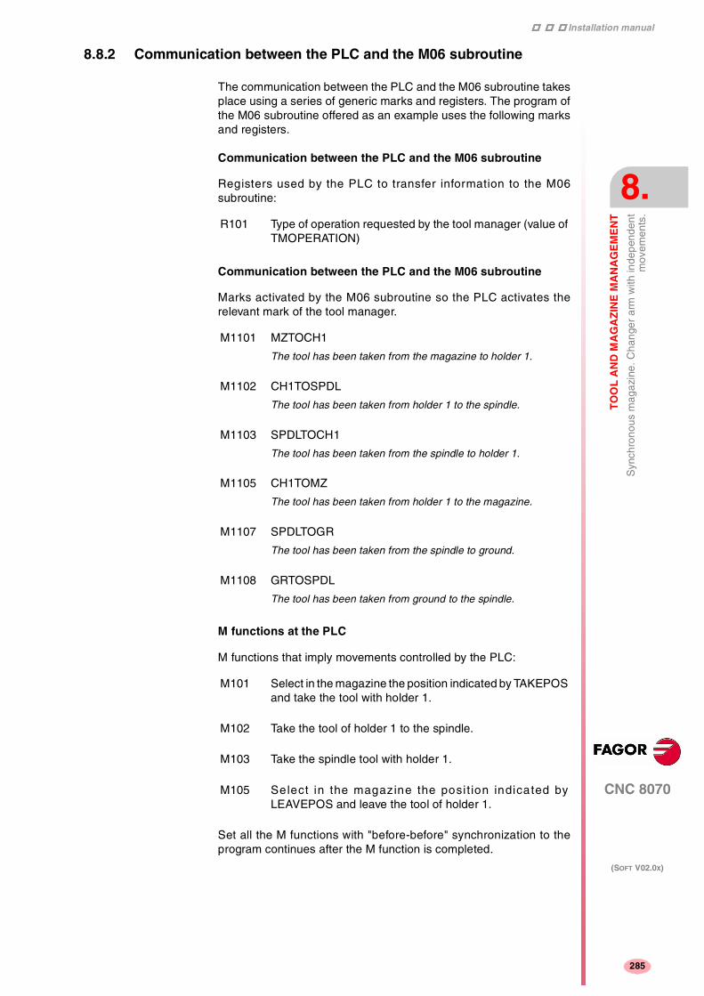
Installation manual
CNC 8070
TO
OL
AN
D M
AG
AZ
INE
MA
NA
GE
ME
NT
Syn
chro
nous
mag
azin
e. C
hang
er a
rm w
ith in
depe
nden
tm
ovem
ents
.
8.
(SOFT V02.0X)
285
8.8.2 Communication between the PLC and the M06 subroutine
The communication between the PLC and the M06 subroutine takesplace using a series of generic marks and registers. The program ofthe M06 subroutine offered as an example uses the following marksand registers.
Communication between the PLC and the M06 subroutine
Registers used by the PLC to transfer information to the M06subroutine:
Communication between the PLC and the M06 subroutine
Marks activated by the M06 subroutine so the PLC activates therelevant mark of the tool manager.
M functions at the PLC
M functions that imply movements controlled by the PLC:
Set all the M functions with "before-before" synchronization to theprogram continues after the M function is completed.
R101 Type of operation requested by the tool manager (value ofTMOPERATION)
M1101 MZTOCH1
The tool has been taken from the magazine to holder 1.
M1102 CH1TOSPDL
The tool has been taken from holder 1 to the spindle.
M1103 SPDLTOCH1
The tool has been taken from the spindle to holder 1.
M1105 CH1TOMZ
The tool has been taken from holder 1 to the magazine.
M1107 SPDLTOGR
The tool has been taken from the spindle to ground.
M1108 GRTOSPDL
The tool has been taken from ground to the spindle.
M101 Select in the magazine the position indicated by TAKEPOSand take the tool with holder 1.
M102 Take the tool of holder 1 to the spindle.
M103 Take the spindle tool with holder 1.
M105 Select in the magazine the posit ion indicated byLEAVEPOS and leave the tool of holder 1.

Installation manual
322
CNC 8070
8.
TO
OL
AN
D M
AG
AZ
INE
MA
NA
GE
ME
NT
Syn
chro
nous
mag
azin
e. C
hang
er a
rm w
ith in
depe
nden
tm
ovem
ents
.
(SOFT V02.0X)
286
8.8.3 Program of the M06 subroutine
%L SUB_MZ_TO_CH1
Take the tool from the magazine with holder 1.
M101
Auxiliary function to execute an action.
V.PLC.M[1101]=1
MZTOCH1 mark to the tool manager.
#RET
%L SUB_CH1_TO_SPD
Take the tool of holder 1 to the spindle.
M102
Auxiliary function to execute an action.
V.PLC.M[1102]=1
CH1TOSPDL mark to the tool manager.
#RET
%L SUB_SPD_TO_CH1
Take the spindle tool with holder 1.
M103
Auxiliary function to execute an action.
V.PLC.M[1103]=1
SPDLTOCH1 mark to the tool manager.
#RET
%L SUB_CH1_TO_MZ
Take the tool of holder 1 to the magazine.
M105
Auxiliary function to execute an action.
V.PLC.M[1105]=1
CH1TOMZ mark to the tool manager.
#RET
%L SUB_SPD_TO_GR
Remove the tool from the spindle (take it to ground).
It shows the message for the operator to extract the tool and waits forthe operation to be completed before removing the message.
#MSG ["Extract Tool. T%D and press cycle-start", V.TM.TOOL]M0#MSG [""]V.PLC.M[1107]=1
SPDLTOGR mark to the tool manager.
#RET

Installation manual
CNC 8070
TO
OL
AN
D M
AG
AZ
INE
MA
NA
GE
ME
NT
Syn
chro
nous
mag
azin
e. C
hang
er a
rm w
ith in
depe
nden
tm
ovem
ents
.
8.
(SOFT V02.0X)
287
%L SUB_GR_TO_SPD
Insert the ground tool in the spindle.
It shows the message for the operator to insert the tool and waits forthe operation to be completed before removing the message.
#MSG ["Insert Tool. T%D and press cycle-start", V.TM.NXTOOL]M0#MSG [""]V.PLC.M[1108]=1
GRTOSPDL mark to the tool manager.
#RET
%L SUB_SPD_GMCHG
Move the spindle to the manual tool change point.
G1 Z_ F_
Move the spindle.
#RET
%L SUB_SPD_AUTCHG
Move the spindle to the automatic tool change point
G1 Z_ F_
Move the spindle.
#RET
%SUB_M6.ncM6
Order the tool manager to start the tool change.
$SWITCH V.PLC.R[101]
It analyzes the type of operation.
$CASE 1
Take a tool from the magazine and insert it in the spindle.
LL SUB_SPD_AUTCHG
Move the spindle to the automatic tool change point
LL SUB_MZ_TO_CH1
Take the tool from the magazine with holder 1.
LL SUB_CH1_TO_SPD
Take the tool of holder 1 to the spindle.
$BREAK
$CASE 2
Leave the spindle tool in the magazine.
LL SUB_SPD_AUTCHG
Move the spindle to the automatic tool change point
LL SUB_SPD_TO_CH1
Take the spindle tool with holder 1.
LL SUB_CH1_TO_MZ
Leave the tool of holder 1 in the magazine.
$BREAK
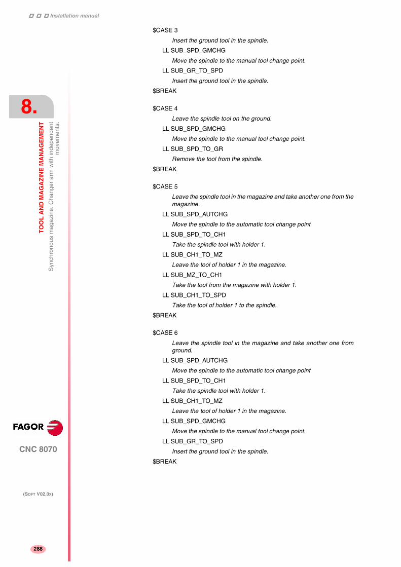
Installation manual
322
CNC 8070
8.
TO
OL
AN
D M
AG
AZ
INE
MA
NA
GE
ME
NT
Syn
chro
nous
mag
azin
e. C
hang
er a
rm w
ith in
depe
nden
tm
ovem
ents
.
(SOFT V02.0X)
288
$CASE 3
Insert the ground tool in the spindle.
LL SUB_SPD_GMCHG
Move the spindle to the manual tool change point.
LL SUB_GR_TO_SPD
Insert the ground tool in the spindle.
$BREAK
$CASE 4
Leave the spindle tool on the ground.
LL SUB_SPD_GMCHG
Move the spindle to the manual tool change point.
LL SUB_SPD_TO_GR
Remove the tool from the spindle.
$BREAK
$CASE 5
Leave the spindle tool in the magazine and take another one from themagazine.
LL SUB_SPD_AUTCHG
Move the spindle to the automatic tool change point
LL SUB_SPD_TO_CH1
Take the spindle tool with holder 1.
LL SUB_CH1_TO_MZ
Leave the tool of holder 1 in the magazine.
LL SUB_MZ_TO_CH1
Take the tool from the magazine with holder 1.
LL SUB_CH1_TO_SPD
Take the tool of holder 1 to the spindle.
$BREAK
$CASE 6
Leave the spindle tool in the magazine and take another one fromground.
LL SUB_SPD_AUTCHG
Move the spindle to the automatic tool change point
LL SUB_SPD_TO_CH1
Take the spindle tool with holder 1.
LL SUB_CH1_TO_MZ
Leave the tool of holder 1 in the magazine.
LL SUB_SPD_GMCHG
Move the spindle to the manual tool change point.
LL SUB_GR_TO_SPD
Insert the ground tool in the spindle.
$BREAK

Installation manual
CNC 8070
TO
OL
AN
D M
AG
AZ
INE
MA
NA
GE
ME
NT
Syn
chro
nous
mag
azin
e. C
hang
er a
rm w
ith in
depe
nden
tm
ovem
ents
.
8.
(SOFT V02.0X)
289
$CASE 7
Leave the spindle tool on the ground and take another one from themagazine.
LL SUB_SPD_GMCHG
Move the spindle to the manual tool change point.
LL SUB_SPD_TO_GR
Remove the tool from the spindle.
LL SUB_SPD_AUTCHG
Move the spindle to the automatic tool change point
LL SUB_MZ_TO_CH1
Take the tool from the magazine with holder 1.
LL SUB_CH1_TO_SPD
Take the tool of holder 1 to the spindle.
$BREAK
$CASE 8
Leave the spindle tool on the ground and take another one fromground.
LL SUB_SPD_GMCHG
Move the spindle to the manual tool change point.
LL SUB_SPD_TO_GR
Remove the tool from the spindle.
LL SUB_GR_TO_SPD
Insert the ground tool in the spindle.
$BREAK
$CASE 9
Take a ground tool to the magazine going through the spindle.
LL SUB_SPD_GMCHG
Move the spindle to the manual tool change point.
LL SUB_GR_TO_SPD
Insert the ground tool in the spindle.
LL SUB_SPD_AUTCHG
Move the spindle to the automatic tool change point
LL SUB_SPD_TO_CH1
Take the spindle tool with holder 1.
LL SUB_CH1_TO_MZ
Leave the tool of holder 1 in the magazine.
$BREAK

Installation manual
322
CNC 8070
8.
TO
OL
AN
D M
AG
AZ
INE
MA
NA
GE
ME
NT
Syn
chro
nous
mag
azin
e. C
hang
er a
rm w
ith in
depe
nden
tm
ovem
ents
.
(SOFT V02.0X)
290
$CASE 10
Take a tool from the magazine and leave on the ground going throughthe spindle.
LL SUB_SPD_AUTCHG
Move the spindle to the automatic tool change point
LL SUB_MZ_TO_CH1
Take the tool from the magazine with holder 1.
LL SUB_CH1_TO_SPD
Take the tool of holder 1 to the spindle.
LL SUB_SPD_GMCHG
Move the spindle to the manual tool change point.
LL SUB_SPD_TO_GR
Remove the tool from the spindle.
$BREAK
$ENDSWITCH
End of analysis of type of operation.
$WHILE V.TM.MZWAIT == 1$ENDWHILE
Wait for the tool manager.
#RET
End of M06 subroutine.

Installation manual
CNC 8070
TO
OL
AN
D M
AG
AZ
INE
MA
NA
GE
ME
NT
Syn
chro
nous
mag
azin
e. C
hang
er a
rm w
ith in
depe
nden
tm
ovem
ents
.
8.
(SOFT V02.0X)
291
8.8.4 Basic PLC programming
When executing the -T- function
When executing a T function, the tool manager sends the codeTMOPERATION=11 to the PLC. In general, it is an optimization of thechange that permits orienting the magazine while machining.
In this case, the magazine is not oriented and the MZROT mark isactivated to indicate that the operation has been completed.
DFU TMOPSTROBE AND CPS TMOPERATION EQ 11 = SET MZROT
Activate the MZROT mark to "tell" the tool manager that the operationhas finished.
When executing the M06 function
When executing the M06 function, the tool manager sends to the PLC,in the TMOPERATION register, the code for the operation to be carriedout.
DFU TMOPSTROBE = MOV TMOPERATION R101
This instruction transfers the TMOPERATION value to register R101 soit is managed by the M06 subroutine.
Every time the M06 subroutine ends an action, it lets the PLC knowso it activates the relevant mark of the tool manager.
DFU M1101 = SET MZTOCH1
DFD MZTOCH1 = RES M1101
The tool has been taken from the magazine to holder 1.
DFU M1102 = SET CH1TOSPDL
DFD CH1TOSPDL = RES M1102
The tool has been taken from holder 1 to the spindle.
DFU M1103 = SET SPDLTOCH1
DFD SPDLTOCH1 = RES M1103
The tool has been taken from the spindle to holder 1.
DFU M1105 = SET CH1TOMZ
DFD CH1TOMZ = RES M1105
The tool has been taken from holder 1 to the magazine.
DFU M1107 = SET SPDLTOGR
DFD SPDLTOGR = RES M1107
The tool has been taken from the spindle to ground.
DFU M1108 = SET GRTOSPDL
DFD GRTOSPDL = RES M1108
The tool has been taken from ground to the spindle.
The M06 subroutine uses the following M functions to "tell" the PLCwhich movements it must carry out.
M101 Select in the magazine the position indicated by TAKEPOSand take the tool with holder 1.
M102 Take the tool of holder 1 to the spindle.
M103 Take the spindle tool with holder 1.
M105 Select in the magazine the posit ion indicated byLEAVEPOS and leave the tool of holder 1.

Installation manual
322
CNC 8070
8.
TO
OL
AN
D M
AG
AZ
INE
MA
NA
GE
ME
NT
Syn
chro
nous
mag
azin
e. C
hang
er a
rm w
ith in
depe
nden
tm
ovem
ents
.
(SOFT V02.0X)
292
Programming it depends on the type of machine. The auxiliaryfunction will conclude after executing the requested movement.
Certain operations require using the information transferred by thetool manager in the following registers:
LEAVEPOS This register indicates the magazine position to leave thetool.
TAKEPOS This register indicates the magazine position of the toolto be taken (picked up).
Manager emergency signal
Treatment of the tool manager emergency signal.
DFU B11KEYBD1 = SET SETTMEM
Pressing the USER12 key activates the emergency.
TMINEM = B11KEYLED1
The lamp of the USER12 key turns on when there is an emergency.
TMINEM AND DFU B12KEYBD1 = SET RESTMEM
Pressing the USER13 key removes the emergency.

Installation manual
CNC 8070
TO
OL
AN
D M
AG
AZ
INE
MA
NA
GE
ME
NT
Syn
chro
nous
mag
azin
e. T
ool c
hang
er a
rm w
ith 2
hol
ders
8.
(SOFT V02.0X)
293
8.9 Synchronous magazine. Tool changer arm with 2 holders
Usually the movements of the changer arm depend on machiningbecause it cannot move while the part is being machined.
The communication between the tool manager and the PLC takesplace in two stages.
• When executing the T function, the CNC lets the tool managerknow about it.
The tool manager sends a command to the PLC to select the nexttool in the magazine (if possible).
The CNC continues with the execution of the program withoutwaiting for the tool manager to complete the operation.
• When executing the M06 function, its associated subroutine iscalled upon.
The M06 function must also be programmed inside that subroutineso the CNC "tells" the tool manager to start making the tool change.
The tool manager sends a command to the PLC to make thechange.
The CNC waits for the tool manager to complete the operationbefore continuing with the execution of the program.
The management of the tool change should be included in thesubroutine associated with the M06 and leave the control of theexternal devices up to the PLC.
Use the auxiliary functions to govern the various devices (magazinerotation, magazine movement, tool changer arm, etc.) from the M06subroutine.

Installation manual
322
CNC 8070
8.
TO
OL
AN
D M
AG
AZ
INE
MA
NA
GE
ME
NT
Syn
chro
nous
mag
azin
e. T
ool c
hang
er a
rm w
ith 2
hol
ders
(SOFT V02.0X)
294
8.9.1 Values of the TMOPERATION and marks to be activated by the PLC
The possible TMOPERATION values in this type of magazine and themarks and registers associated with each case are:
TMOPERATION=1 Take a tool from the magazine and insert it in the spindle.
TAKEPOS Position occupied by the tool.
1. Take the tool from the magazine with holder 1 and activate the markMZTOCH1.
2. Insert the tool of holder 1 in the spindle and activate CH1TOSPDL.
TMOPERATION=2 Leave the spindle tool in the magazine.
LEAVEPOS Position to leave the tool.
1. Take the tool from the spindle with holder 2 and activate the markSPDLTOCH1.
2. Leave the tool of holder 2 in the magazine and activate themarkCH2TOMZ.
TMOPERATION=3 Insert a ground tool in the spindle.
TAKEPOS=-4 Pick up the ground tool.
When the operation is completed, activate the mark GRTOSPDL.
TMOPERATION=4 Leave the spindle tool on the ground.
LEAVEPOS=-4 Leave the tool on the ground.
When the operation is completed, activate the mark SPDLTOGR.
TMOPERATION=5 Leave the spindle tool in the magazine and take another one from themagazine.
TAKEPOS Position occupied by the tool.
LEAVEPOS Position to leave the tool.
1. Take the tool from the spindle with holder 2 and activate the markSPDLTOCH1.
2. Take the tool from the magazine with holder 1 and activate the markMZTOCH1.
3. Leave the tool of holder 2 in the magazine and activate themarkCH2TOMZ.
4. Insert the tool of holder 1 in the spindle and activate CH1TOSPDL.
The tool manager also admits the sequences 1-2-4-3, 2-1-3-4, 2-1-4-3
TMOPERATION=6 Leave the spindle tool in the magazine and take another one fromground.
TAKEPOS=-4 Pick up the ground tool.
LEAVEPOS Position to leave the tool.
1. Take the tool from the spindle with holder 2 and activate the markSPDLTOCH1.
2. Leave the tool of holder 2 in the magazine and activate themarkCH2TOMZ.
3. Leave the ground tool in the spindle and activate the markGRTOSPDL.
The tool manager admits the sequence 1-3-2.

Installation manual
CNC 8070
TO
OL
AN
D M
AG
AZ
INE
MA
NA
GE
ME
NT
Syn
chro
nous
mag
azin
e. T
ool c
hang
er a
rm w
ith 2
hol
ders
8.
(SOFT V02.0X)
295
TMOPERATION=7 Leave the spindle tool on the ground and take another one from themagazine.
TAKEPOS Position occupied by the tool.
LEAVEPOS=-4 Leave the tool on the ground.
1. Leave the tool of the spindle on the ground and activate the markSPDLTOGR.
2. Take the tool from the magazine with holder 1 and activate the markMZTOCH1.
3. Insert the tool of holder 1 in the spindle and activate CH1TOSPDL.
The tool manager admits the sequence 2-1-3.
TMOPERATION=8 Leave the spindle tool on the ground and take another one fromground.
TAKEPOS=-4 Pick up the ground tool.
LEAVEPOS=-4 Leave the tool on the ground.
1. Leave the tool of the spindle on the ground and activate the markSPDLTOGR.
2. Leave the ground tool in the spindle and activate the markGRTOSPDL.
TMOPERATION=9 Take a ground tool to the magazine going through the spindle.
TAKEPOS=-4 Pick up the ground tool.
LEAVEPOS Position to leave the tool.
1. Leave the ground tool in the spindle and activate the markGRTOSPDL.
2. Take the tool from the spindle with holder 2 and activate the markSPDLTOCH1.
3. Leave the tool of holder 2 in the magazine and activate themarkCH2TOMZ.
TMOPERATION=10 Take a tool from the magazine and leave on the ground going throughthe spindle.
TAKEPOS Position occupied by the tool.
LEAVEPOS=-4 Leave the tool on the ground.
1. Take the tool from the magazine with holder 1 and activate the markMZTOCH1.
2. Insert the tool of holder 1 in the spindle and activate CH1TOSPDL.
3. Leave the tool of the spindle on the ground and activate the markSPDLTOGR.
TMOPERATION=11 In general, it is an optimization of the change that permits orientingthe magazine while machining.
Activate the MZROT mark to indicate that the operation has beencompleted, whether it has been oriented or not.
TMOPERATION=12 Same as TMOPERATION=5. It is only used when the magazine isnon-random. Also for random magazines when having special tools.
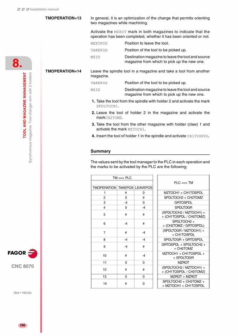
Installation manual
322
CNC 8070
8.
TO
OL
AN
D M
AG
AZ
INE
MA
NA
GE
ME
NT
Syn
chro
nous
mag
azin
e. T
ool c
hang
er a
rm w
ith 2
hol
ders
(SOFT V02.0X)
296
TMOPERATION=13 In general, it is an optimization of the change that permits orientingtwo magazines while machining.
Activate the MZROT mark in both magazines to indicate that theoperation has been completed, whether it has been oriented or not.
NEXTPOS Position to leave the tool.
TAKEPOS Position of the tool to be picked up.
MZID Destination magazine to leave the tool and sourcemagazine from which to pick up the new one.
TMOPERATION=14 Leave the spindle tool in a magazine and take a tool from anothermagazine.
TAKEPOS Position of the tool to be picked up.
MZID Destination magazine to leave the tool and sourcemagazine from which to pick up the new one.
1. Take the tool from the spindle with holder 2 and activate the markSPDLTOCH1.
2. Leave the tool of holder 2 in the magazine and activate themarkCH2TOMZ.
3. Take the tool from the other magazine with holder (claw) 1 andactivate the mark MZTOCH1.
4. Insert the tool of holder 1 in the spindle and activate CH1TOSPDL.
Summary
The values sent by the tool manager to the PLC in each operation andthe marks to be activated by the PLC are the following:
TM ==> PLC
PLC ==> TM
TMOPERATION TAKEPOS LEAVEPOS
1 # 0 MZTOCH1 + CH1TOSPDL
2 0 # SPDLTOCH2 + CH2TOMZ
3 -4 0 GRTOSPDL
4 0 -4 SPDLTOGR
5 # #(SPDLTOCH2 / MZTOCH1) ++ (CH1TOSPDL / CH2TOMZ)
6 -4 #SPDLTOCH2 +
+ (CH2TOMZ / GRTOSPDL)
7 # -4(SPDLTOGR / MZTOCH1) +
+ CH1TOSPDL
8 -4 -4 SPDLTOGR + GRTOSPDL
9 -4 #GRTOSPDL + SPDLTOCH2 +
+ CH2TOMZ
10 # -4MZTOCH1 + CH1TOSPDL +
+ SPDLTOGR
11 0 0 MZROT
12 # #(SPDLTOCH2 / MZTOCH1) ++ (CH1TOSPDL / CH2TOMZ)
13 0 0 MZROT + MZROT
14 # 0SPDLTOCH2 + CH2TOMZ ++ MZTOCH1 + CH1TOSPDL

Installation manual
CNC 8070
TO
OL
AN
D M
AG
AZ
INE
MA
NA
GE
ME
NT
Syn
chro
nous
mag
azin
e. T
ool c
hang
er a
rm w
ith 2
hol
ders
8.
(SOFT V02.0X)
297
The marks in parenthesis may be executed in any order; but both mustbe executed. Possibilities with TMOPERATION = 6:
SPDLTOCH2 + CH2TOMZ + GRTOSPDL
SPDLTOCH2 + GRTOSPDL + CH2TOMZ
The TAKEPOS and LEAVEPOS values indicate the following:
0 Do nothing.
# Magazine position number.
-4 Ground position.
Application example
Assuming that there is no tool in the spindle, it shows the functionsexecuted by the CNC, the values sent by the tool manager to the PLCin each operation and the marks to be activated by the PLC in eachcase.
It is a non-random magazine, each tool occupies the position of its ownnumber and TG7, TG8 and TG9 are ground tools.
CNCTM ==> PLC
PLC ==> TMTMOPERATION TAKEPOS LEAVEPOS
T1M6
111
0A
00
MZROTMZTOCH1 + CH1TOSPDL
T2M6
115
0B
0B
MZROTMZTOCH1 + SPDLTOCH2 ++ CH1TOSPDL + CH2TOMZ
TG7M6
116
0-4
0A
MZROTSPDLTOCH2 + CH2TOMZ +
+ GRTOSPDL
TG8M6
118
0-4
0-4
MZROTSPDLTOGR + GRTOSPDL
T3T4M6
11117
00D
00-4
MZROTMZROT
SPDLTOGR + MZTOCH1 ++ CH1TOSPDL
T0M6
112
00
0D
MZROTSPDLTOCH2 + CH2TOMZ
TG9M6
113
0-4
00
MZROTGRTOSPDL
T0M6
114
00
0-4
MZROTSPDLTOGR

Installation manual
322
CNC 8070
8.
TO
OL
AN
D M
AG
AZ
INE
MA
NA
GE
ME
NT
Syn
chro
nous
mag
azin
e. T
ool c
hang
er a
rm w
ith 2
hol
ders
(SOFT V02.0X)
298
8.9.2 Communication between the PLC and the M06 subroutine
The communication between the PLC and the M06 subroutine takesplace using a series of generic marks and registers. The program ofthe M06 subroutine offered as an example uses the following marksand registers.
Communication between the PLC and the M06 subroutine
Registers used by the PLC to transfer information to the M06subroutine:
Communication between the PLC and the M06 subroutine
Marks activated by the M06 subroutine so the PLC activates therelevant mark of the tool manager.
M functions at the PLC
M functions that imply movements controlled by the PLC:
Set all the M functions with "before-before" synchronization to theprogram continues after the M function is completed.
R101 Type of operation requested by the tool manager (value ofTMOPERATION)
M1101 MZTOCH1
The tool has been taken from the magazine to holder 1.
M1102 CH1TOSPDL
The tool has been taken from holder 1 to the spindle.
M1104 SPDLTOCH2
The tool has been taken from the spindle to holder 2.
M1106 CH2TOMZ
The tool has been taken from holder 2 to the magazine.
M1107 SPDLTOGR
The tool has been taken from the spindle to ground.
M1108 GRTOSPDL
The tool has been taken from ground to the spindle.
M101 Select in the magazine the position indicated by TAKEPOSand take the tool with holder 1.
M102 Take the tool of holder 1 to the spindle.
M104 Take the spindle tool with holder 2.
M106 Select in the magazine the posit ion indicated byLEAVEPOS and leave the tool of holder 2.

Installation manual
CNC 8070
TO
OL
AN
D M
AG
AZ
INE
MA
NA
GE
ME
NT
Syn
chro
nous
mag
azin
e. T
ool c
hang
er a
rm w
ith 2
hol
ders
8.
(SOFT V02.0X)
299
8.9.3 Program of the M06 subroutine
%L SUB_MZ_TO_CH1
Take the tool from the magazine with holder 1.
M101
Auxiliary function to execute an action.
V.PLC.M[1101]=1
MZTOCH1 mark to the tool manager.
#RET
%L SUB_CH1_TO_SPD
Take the tool of holder 1 to the spindle.
M102
Auxiliary function to execute an action.
V.PLC.M[1102]=1
CH1TOSPDL mark to the tool manager.
#RET
%L SUB_SPD_TO_CH2
Take the spindle tool with holder 2.
M104
Auxiliary function to execute an action.
V.PLC.M[1104]=1
SPDLTOCH2 mark to the tool manager.
#RET
%L SUB_CH2_TO_MZ
Take the tool of holder 2 to the magazine.
M106
Auxiliary function to execute an action.
V.PLC.M[1106]=1
CH2TOMZ mark to the tool manager.
#RET
%L SUB_SPD_TO_GR
Remove the tool from the spindle (take it to ground).
It shows the message for the operator to extract the tool and waits forthe operation to be completed before removing the message.
#MSG ["Extract Tool. T%D and press cycle-start", V.TM.TOOL]M0#MSG [""]V.PLC.M[1107]=1
SPDLTOGR mark to the tool manager.
#RET

Installation manual
322
CNC 8070
8.
TO
OL
AN
D M
AG
AZ
INE
MA
NA
GE
ME
NT
Syn
chro
nous
mag
azin
e. T
ool c
hang
er a
rm w
ith 2
hol
ders
(SOFT V02.0X)
300
%L SUB_GR_TO_SPD
Insert the ground tool in the spindle.
It shows the message for the operator to insert the tool and waits forthe operation to be completed before removing the message.
#MSG ["Insert Tool. T%D and press cycle-start", V.TM.NXTOOL]M0#MSG [""]V.PLC.M[1108]=1
GRTOSPDL mark to the tool manager.
#RET
%L SUB_SPD_GMCHG
Move the spindle to the manual tool change point.
G1 Z_ F_
Move the spindle.
#RET
%L SUB_SPD_AUTCHG
Move the spindle to the automatic tool change point
G1 Z_ F_
Move the spindle.
#RET
%SUB_M6.ncM6
Order the tool manager to start the tool change.
$SWITCH V.PLC.R[101]
It analyzes the type of operation.
$CASE 1
Take a tool from the magazine and insert it in the spindle.
LL SUB_SPD_AUTCHG
Move the spindle to the automatic tool change point
LL SUB_MZ_TO_CH1
Take the tool from the magazine with holder 1.
LL SUB_CH1_TO_SPD
Take the tool of holder 1 to the spindle.
$BREAK
$CASE 2
Leave the spindle tool in the magazine.
LL SUB_SPD_AUTCHG
Move the spindle to the automatic tool change point
LL SUB_SPD_TO_CH2
Take the spindle tool with holder 2.
LL SUB_CH2_TO_MZ
Leave the tool of holder 2 in the magazine.
$BREAK

Installation manual
CNC 8070
TO
OL
AN
D M
AG
AZ
INE
MA
NA
GE
ME
NT
Syn
chro
nous
mag
azin
e. T
ool c
hang
er a
rm w
ith 2
hol
ders
8.
(SOFT V02.0X)
301
$CASE 3
Insert the ground tool in the spindle.
LL SUB_SPD_GMCHG
Move the spindle to the manual tool change point.
LL SUB_GR_TO_SPD
Insert the ground tool in the spindle.
$BREAK
$CASE 4
Leave the spindle tool on the ground.
LL SUB_SPD_GMCHG
Move the spindle to the manual tool change point.
LL SUB_SPD_TO_GR
Remove the tool from the spindle.
$BREAK
$CASE 5
Leave the spindle tool in the magazine and take another one from themagazine.
LL SUB_SPD_AUTCHG
Move the spindle to the automatic tool change point
LL SUB_SPD_TO_CH2
Take the spindle tool with holder 2.
LL SUB_MZ_TO_CH1
Take the tool from the magazine with holder 1.
LL SUB_CH2_TO_MZ
Leave the tool of holder 2 in the magazine.
LL SUB_CH1_TO_SPD
Take the tool of holder 1 to the spindle.
$BREAK
$CASE 6
Leave the spindle tool in the magazine and take another one fromground.
LL SUB_SPD_AUTCHG
Move the spindle to the automatic tool change point
LL SUB_SPD_TO_CH2
Take the spindle tool with holder 2.
LL SUB_CH2_TO_MZ
Leave the tool of holder 2 in the magazine.
LL SUB_SPD_GMCHG
Move the spindle to the manual tool change point.
LL SUB_GR_TO_SPD
Insert the ground tool in the spindle.
$BREAK

Installation manual
322
CNC 8070
8.
TO
OL
AN
D M
AG
AZ
INE
MA
NA
GE
ME
NT
Syn
chro
nous
mag
azin
e. T
ool c
hang
er a
rm w
ith 2
hol
ders
(SOFT V02.0X)
302
$CASE 7
Leave the spindle tool on the ground and take another one from themagazine.
LL SUB_SPD_GMCHG
Move the spindle to the manual tool change point.
LL SUB_SPD_TO_GR
Remove the tool from the spindle.
LL SUB_SPD_AUTCHG
Move the spindle to the automatic tool change point
LL SUB_MZ_TO_CH1
Take the tool from the magazine with holder 1.
LL SUB_CH1_TO_SPD
Take the tool of holder 1 to the spindle.
$BREAK
$CASE 8
Leave the spindle tool on the ground and take another one fromground.
LL SUB_SPD_GMCHG
Move the spindle to the manual tool change point.
LL SUB_SPD_TO_GR
Remove the tool from the spindle.
LL SUB_GR_TO_SPD
Insert the ground tool in the spindle.
$BREAK
$CASE 9
Take a ground tool to the magazine going through the spindle.
LL SUB_SPD_GMCHG
Move the spindle to the manual tool change point.
LL SUB_GR_TO_SPD
Insert the ground tool in the spindle.
LL SUB_SPD_AUTCHG
Move the spindle to the automatic tool change point
LL SUB_SPD_TO_CH2
Take the spindle tool with holder 2.
LL SUB_CH2_TO_MZ
Leave the tool of holder 2 in the magazine.
$BREAK

Installation manual
CNC 8070
TO
OL
AN
D M
AG
AZ
INE
MA
NA
GE
ME
NT
Syn
chro
nous
mag
azin
e. T
ool c
hang
er a
rm w
ith 2
hol
ders
8.
(SOFT V02.0X)
303
$CASE 10
Take a tool from the magazine and leave on the ground going throughthe spindle.
LL SUB_SPD_AUTCHG
Move the spindle to the automatic tool change point
LL SUB_MZ_TO_CH1
Take the tool from the magazine with holder 1.
LL SUB_CH1_TO_SPD
Take the tool of holder 1 to the spindle.
LL SUB_SPD_GMCHG
Move the spindle to the manual tool change point.
LL SUB_SPD_TO_GR
Remove the tool from the spindle.
$BREAK
$ENDSWITCH
End of analysis of type of operation.
$WHILE V.TM.MZWAIT == 1$ENDWHILE
Wait for the tool manager.
#RET
End of M06 subroutine.

Installation manual
322
CNC 8070
8.
TO
OL
AN
D M
AG
AZ
INE
MA
NA
GE
ME
NT
Syn
chro
nous
mag
azin
e. T
ool c
hang
er a
rm w
ith 2
hol
ders
(SOFT V02.0X)
304
8.9.4 Basic PLC programming
When executing the -T- function
When executing a T function, the tool manager sends the codeTMOPERATION=11 to the PLC. In general, it is an optimization of thechange that permits orienting the magazine while machining.
In this case, the magazine is not oriented and the MZROT mark isactivated to indicate that the operation has been completed.
DFU TMOPSTROBE AND CPS TMOPERATION EQ 11 = SET MZROT
Activate the MZROT mark to "tell" the tool manager that the operationhas finished.
When executing the M06 function
When executing the M06 function, the tool manager sends to the PLC,in the TMOPERATION register, the code for the operation to be carriedout.
DFU TMOPSTROBE = MOV TMOPERATION R101
This instruction transfers the TMOPERATION value to register R101 soit is managed by the M06 subroutine.
Every time the M06 subroutine ends an action, it lets the PLC knowso it activates the relevant mark of the tool manager.
DFU M1101 = SET MZTOCH1
DFD MZTOCH1 = RES M1101
The tool has been taken from the magazine to holder 1.
DFU M1102 = SET CH1TOSPDL
DFD CH1TOSPDL = RES M1102
The tool has been taken from holder 1 to the spindle.
DFU M1104 = SET SPDLTOCH2
DFD SPDLTOCH2 = RES M1104
The tool has been taken from the spindle to holder 2.
DFU M1106 = SET CH2TOMZ
DFD CH2TOMZ = RES M1106
The tool has been taken from holder 2 to the magazine.
DFU M1107 = SET SPDLTOGR
DFD SPDLTOGR = RES M1107
The tool has been taken from the spindle to ground.
DFU M1108 = SET GRTOSPDL
DFD GRTOSPDL = RES M1108
The tool has been taken from ground to the spindle.
The M06 subroutine uses the following M functions to "tell" the PLCwhich movements it must carry out.
M101 Select in the magazine the position indicated by TAKEPOSand take the tool with holder 1.
M102 Take the tool of holder 1 to the spindle.
M104 Take the spindle tool with holder 2.
M106 Select in the magazine the posit ion indicated byLEAVEPOS and leave the tool of holder 2.

Installation manual
CNC 8070
TO
OL
AN
D M
AG
AZ
INE
MA
NA
GE
ME
NT
Syn
chro
nous
mag
azin
e. T
ool c
hang
er a
rm w
ith 2
hol
ders
8.
(SOFT V02.0X)
305
Programming it depends on the type of machine. The auxiliaryfunction will conclude after executing the requested movement.
Certain operations require using the information transferred by thetool manager in the following registers:
LEAVEPOS This register indicates the magazine position to leave thetool.
TAKEPOS This register indicates the magazine position of the toolto be taken (picked up).
Manager emergency signal
Treatment of the tool manager emergency signal.
DFU B11KEYBD1 = SET SETTMEM
Pressing the USER12 key activates the emergency.
TMINEM = B11KEYLED1
The lamp of the USER12 key turns on when there is an emergency.
TMINEM AND DFU B12KEYBD1 = SET RESTMEM
Pressing the USER13 key removes the emergency.

Installation manual
322
CNC 8070
8.
TO
OL
AN
D M
AG
AZ
INE
MA
NA
GE
ME
NT
Asy
nchr
onou
s m
agaz
ine
(SOFT V02.0X)
306
8.10 Asynchronous magazine
Usually, the tool magazine is located away from the spindle and themovements of the changer arm are independent. It is recommendedto take and leave the tool in the magazine while machining the part.
The communication between the tool manager and the PLC takesplace in two stages.
• When executing the T function, the CNC lets the tool managerknow about it.
The tool manager sends a command to the PLC to select the nexttool in the magazine (if possible).
The CNC continues with the execution of the program withoutwaiting for the tool manager to complete the operation.
• When executing the M06 function, its associated subroutine iscalled upon.
The M06 function must also be programmed inside that subroutineso the CNC "tells" the tool manager to start making the tool change.
The tool manager sends a command to the PLC to make thechange.
The CNC waits for the tool manager to complete the operationbefore continuing with the execution of the program.
The management of the tool change should be included in thesubroutine associated with the M06 and leave the control of theexternal devices up to the PLC.
Use the auxiliary functions to govern the various devices (magazinerotation, magazine movement, tool changer arm, etc.) from the M06subroutine.
If the tool change implies leaving a tool in the magazine, onceexecuted the change and with the tool in the arm, it is possible toactivate the TCHANGEOK mark for the CNC to continue executing theprogram while the tool is being left in the magazine.

Installation manual
CNC 8070
TO
OL
AN
D M
AG
AZ
INE
MA
NA
GE
ME
NT
Asy
nchr
onou
s m
agaz
ine
8.
(SOFT V02.0X)
307
8.10.1 Values of the TMOPERATION and marks to be activated by the PLC
The possible TMOPERATION values in this type of magazine and themarks and registers associated with each case are:
TMOPERATION=1 Take a tool from the magazine and insert it in the spindle.
Previously, while machining (when executing the T), it sends theTMOPERATION=11 code to pick up the tool from the magazine withholder 1. Now it is done with TMOPERATION=1.
TAKEPOS=-1 Pick up the tool from holder 1.
1. Insert the tool of holder 1 in the spindle and activate CH1TOSPDL.
TMOPERATION=2 Leave the spindle tool in the magazine.
LEAVEPOS Position to leave the tool.
1. Take the tool from the spindle with holder 2 and activate the markSPDLTOCH1.
2. Start sending the changer arm to the magazine to leave the toolin holder 2.
3. When the arm leaves the collision zone, activate TCHANGEOK, if sodesired, to continue executing the program.
4. Leave the tool of holder 2 in the magazine and activate themarkCH2TOMZ.
TMOPERATION=3 Insert a ground tool in the spindle.
TAKEPOS=-4 Pick up the ground tool.
When the operation is completed, activate the mark GRTOSPDL.
TMOPERATION=4 Leave the spindle tool on the ground.
LEAVEPOS=-4 Leave the tool on the ground.
When the operation is completed, activate the mark SPDLTOGR.
TMOPERATION=5 Leave the spindle tool in the magazine and take another one from themagazine.
Previously, while machining (when executing the T), it sends theTMOPERATION=11 code to pick up the tool from the magazine withholder 1. Now it is done with TMOPERATION=5.
TAKEPOS=-1 Pick up the tool from holder 1.
LEAVEPOS Position to leave the tool.
The tool manager admits 2 sequences. First sequence.
1. Take the tool from the spindle with holder 2 and activate the markSPDLTOCH1.
2. Leave the tool of holder 2 in the magazine and activate themarkCH2TOMZ.
3. Insert the tool of holder 1 in the spindle and activate CH1TOSPDL.
Second sequence.
1. Take the tool from the spindle with holder 2 and activate the markSPDLTOCH1.
2. Insert the tool of holder 1 in the spindle and activate CH1TOSPDL.
3. Start sending the changer arm to the magazine to leave the toolin holder 2.

Installation manual
322
CNC 8070
8.
TO
OL
AN
D M
AG
AZ
INE
MA
NA
GE
ME
NT
Asy
nchr
onou
s m
agaz
ine
(SOFT V02.0X)
308
4. When the arm leaves the collision zone, activate TCHANGEOK, if sodesired, to continue executing the program.
5. Leave the tool of holder 2 in the magazine and activate themarkCH2TOMZ.
TMOPERATION=6 Leave the spindle tool in the magazine and take another one fromground.
TAKEPOS=-4 Pick up the ground tool.
LEAVEPOS Position to leave the tool.
The tool manager admits 2 sequences. First sequence.
1. Take the tool from the spindle with holder 2 and activate the markSPDLTOCH1.
2. Leave the tool of holder 2 in the magazine and activate themarkCH2TOMZ.
3. Leave the ground tool in the spindle and activate the markGRTOSPDL.
Second sequence.
1. Take the tool from the spindle with holder 2 and activate the markSPDLTOCH1.
2. Leave the ground tool in the spindle and activate the markGRTOSPDL.
3. Start sending the changer arm to the magazine to leave the toolin holder 2.
4. When the arm leaves the collision zone, activate TCHANGEOK, if sodesired, to continue executing the program.
5. Leave the tool of holder 2 in the magazine and activate themarkCH2TOMZ.
TMOPERATION=7 Leave the spindle tool on the ground and take another one from themagazine.
Previously, while machining (when executing the T), it sends theTMOPERATION=11 code to pick up the tool from the magazine withholder 1. Now it is done with TMOPERATION=7.
TAKEPOS=-1 Pick up the tool from holder 1.
LEAVEPOS=-4 Leave the tool on the ground.
1. Leave the tool of the spindle on the ground and activate the markSPDLTOGR.
2. Insert the tool of holder 1 in the spindle and activate CH1TOSPDL.
TMOPERATION=8 Leave the spindle tool on the ground and take another one fromground.
TAKEPOS=-4 Pick up the ground tool.
LEAVEPOS=-4 Leave the tool on the ground.
1. Leave the tool of the spindle on the ground and activate the markSPDLTOGR.
2. Leave the ground tool in the spindle and activate the markGRTOSPDL.
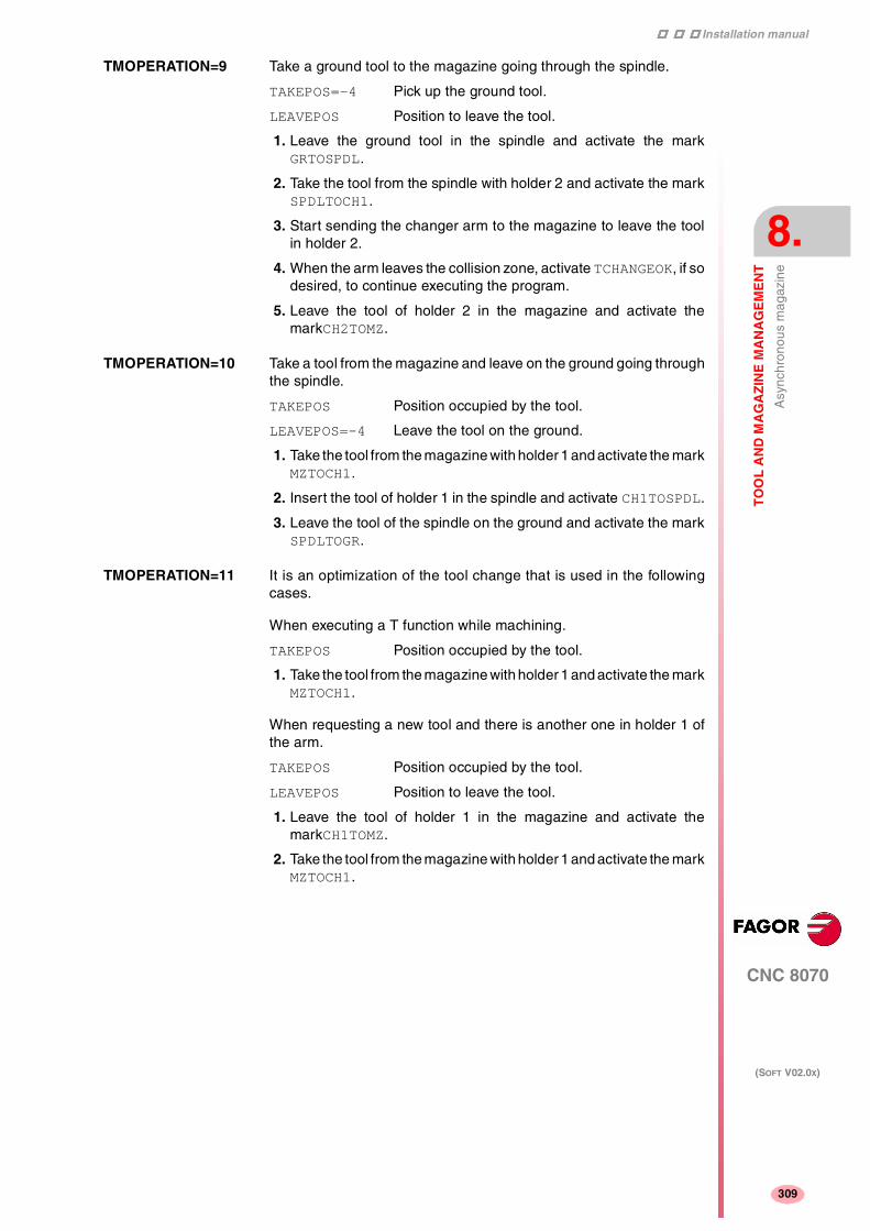
Installation manual
CNC 8070
TO
OL
AN
D M
AG
AZ
INE
MA
NA
GE
ME
NT
Asy
nchr
onou
s m
agaz
ine
8.
(SOFT V02.0X)
309
TMOPERATION=9 Take a ground tool to the magazine going through the spindle.
TAKEPOS=-4 Pick up the ground tool.
LEAVEPOS Position to leave the tool.
1. Leave the ground tool in the spindle and activate the markGRTOSPDL.
2. Take the tool from the spindle with holder 2 and activate the markSPDLTOCH1.
3. Start sending the changer arm to the magazine to leave the toolin holder 2.
4. When the arm leaves the collision zone, activate TCHANGEOK, if sodesired, to continue executing the program.
5. Leave the tool of holder 2 in the magazine and activate themarkCH2TOMZ.
TMOPERATION=10 Take a tool from the magazine and leave on the ground going throughthe spindle.
TAKEPOS Position occupied by the tool.
LEAVEPOS=-4 Leave the tool on the ground.
1. Take the tool from the magazine with holder 1 and activate the markMZTOCH1.
2. Insert the tool of holder 1 in the spindle and activate CH1TOSPDL.
3. Leave the tool of the spindle on the ground and activate the markSPDLTOGR.
TMOPERATION=11 It is an optimization of the tool change that is used in the followingcases.
When executing a T function while machining.
TAKEPOS Position occupied by the tool.
1. Take the tool from the magazine with holder 1 and activate the markMZTOCH1.
When requesting a new tool and there is another one in holder 1 ofthe arm.
TAKEPOS Position occupied by the tool.
LEAVEPOS Position to leave the tool.
1. Leave the tool of holder 1 in the magazine and activate themarkCH1TOMZ.
2. Take the tool from the magazine with holder 1 and activate the markMZTOCH1.

Installation manual
322
CNC 8070
8.
TO
OL
AN
D M
AG
AZ
INE
MA
NA
GE
ME
NT
Asy
nchr
onou
s m
agaz
ine
(SOFT V02.0X)
310
TMOPERATION=14 Leave the spindle tool in a magazine and take a tool from anothermagazine.
Previously, while machining (when executing the T), it sends theTMOPERATION=11 code to pick up the tool from the magazine withholder (claw) 1. Now it is done with TMOPERATION=14.
TAKEPOS Position of the tool to be picked up.
LEAVEPOS Position to leave the tool.
MZID Destination magazine to leave the tool and sourcemagazine from which to pick up the new one.
1. Take the tool from the spindle with holder 2 and activate the markSPDLTOCH1.
2. Leave the tool of holder 2 in the magazine and activate themarkCH2TOMZ.
3. Insert the tool of holder 1 in the spindle and activate CH1TOSPDL.
Summary
The values sent by the tool manager to the PLC in each operation andthe marks to be activated by the PLC are the following:
There are 2 possible sequences in operations 5 and 6. There may betwo cases in operation 11.
The TCHANGEOK mark is optional. Once the tool change is done andthe tool is in the arm, it must be used when it is possible to executethe program while leaving the tool in the magazine.
TM ==> PLCPLC ==> TM
TMOPERATION TAKEPOS LEAVEPOS
1 -1 0 CH1TOSPDL
2 0 #SPDLTOCH2 + [TCHANGEOK] +
+ CH2TOMZ
3 -4 0 GRTOSPDL
4 0 -4 SPDLTOGR
5 -1 #
a) SPDLTOCH2 + CH2TOMZ ++ CH1TOSPDL
b) SPDLTOCH2 + CH1TOSPDL+ [TCHANGEOK] + CH2TOMZ
6 -4 #
a) SPDLTOCH2 + CH2TOMZ ++ GRTOSPDL
b) SPDLTOCH2 + GRTOSPDL+ [TCHANGEOK] + CH2TOMZ
7 -1 -4 SPDLTOGR + CH1TOSPDL
8 -4 -4 SPDLTOGR + GRTOSPDL
9 -4 #GRTOSPDL + SPDLTOCH2 ++ [TCHANGEOK] + CH2TOMZ
10 # -4MZTOCH1 + CH1TOSPDL +
+ SPDLTOGR
11 ? ?1) IF LEAVEPOS=# CH1TOMZ2) IF TAKEPOS=# MZTOCH1
14 -1 #SPDLTOCH2 + CH2TOMZ +
CH1TOSPDL

Installation manual
CNC 8070
TO
OL
AN
D M
AG
AZ
INE
MA
NA
GE
ME
NT
Asy
nchr
onou
s m
agaz
ine
8.
(SOFT V02.0X)
311
The TAKEPOS and LEAVEPOS values indicate the following:
0 Do nothing.
# Magazine position number.
-1 Holder 1 of the tool changer arm.
-4 Ground position.
Application example
Assuming that there is no tool in the spindle, it shows the functionsexecuted by the CNC, the values sent by the tool manager to the PLCin each operation and the marks to be activated by the PLC in eachcase.
It is a non-random magazine, each tool occupies the position of its ownnumber and TG7, TG8 and TG9 are ground tools.
CNCTM ==> PLC
PLC ==> TMTMOPERATION TAKEPOS LEAVEPOS
T1M6
111
1-1
00
MZTOCH1CH1TOSPDL
T2M6
115
2-1
01
MZTOCH1SPDLTOCH2 + CH1TOSPDL +
+ CH2TOMZ
TG7M6
116
0-4
00
MZROTSPDLTOCH2 + CH2TOMZ +
+ GRTOSPDL
TG8M6
118
0-4
0-4
MZROTSPDLTOGR + GRTOSPDL
T3T4M6
11117
34-1
03-4
MZTOCH1CH1TOMZ + MZTOCH1
SPDLTOGR + + CH1TOSPDL
T0M6
112
00
04
MZROTSPDLTOCH2 + CH2TOMZ
TG9M6
113
0-4
00
MZROTGRTOSPDL
T0M6
114
00
0-4
MZROTSPDLTOGR

Installation manual
322
CNC 8070
8.
TO
OL
AN
D M
AG
AZ
INE
MA
NA
GE
ME
NT
Asy
nchr
onou
s m
agaz
ine
(SOFT V02.0X)
312
8.10.2 Communication between the PLC and the M06 subroutine
The communication between the PLC and the M06 subroutine takesplace using a series of generic marks and registers. The program ofthe M06 subroutine offered as an example uses the following marksand registers.
Communication between the PLC and the M06 subroutine
Registers used by the PLC to transfer information to the M06subroutine:
Communication between the PLC and the M06 subroutine
Marks activated by the M06 subroutine so the PLC activates therelevant mark of the tool manager.
The PLC sets the CH2TOMZ mark when the tool has been left.
M functions at the PLC
M functions that imply movements controlled by the PLC:
R101 Type of operation requested by the tool manager (value ofTMOPERATION)
M1100 TCHANGEOK
Continue executing the program.
M1101 MZTOCH1
The tool has been taken from the magazine to holder 1.
M1102 CH1TOSPDL
The tool has been taken from holder 1 to the spindle.
M1104 SPDLTOCH2
The tool has been taken from the spindle to holder 2.
M1107 SPDLTOGR
The tool has been taken from the spindle to ground.
M1108 GRTOSPDL
The tool has been taken from ground to the spindle.
M101 Select in the magazine the position indicated by TAKEPOSand take the tool with holder 1.
M102 Take the tool of holder 1 to the spindle.
M104 Take the spindle tool with holder 2.
M106 Start sending the changer arm to the magazine to leave thetool in holder 2.
M121 Take the changer arm to the change point.
M122 Take the changer arm to the magazine.
M123 Retract the changer arm.

Installation manual
CNC 8070
TO
OL
AN
D M
AG
AZ
INE
MA
NA
GE
ME
NT
Asy
nchr
onou
s m
agaz
ine
8.
(SOFT V02.0X)
313
Set all the M functions with "before-before" synchronization to theprogram continues after the M function is completed.
The PLC must consider the M106 completed when the arm exits thecollision zone and machining is possible.

Installation manual
322
CNC 8070
8.
TO
OL
AN
D M
AG
AZ
INE
MA
NA
GE
ME
NT
Asy
nchr
onou
s m
agaz
ine
(SOFT V02.0X)
314
8.10.3 Program of the M06 subroutine
%L SUB_MZ_TO_CH1
Take the tool from the magazine with holder 1.
M101
Auxiliary function to execute an action.
V.PLC.M[1101]=1
MZTOCH1 mark to the tool manager.
#RET
%L SUB_CH1_TO_SPD
Take the tool of holder 1 to the spindle.
M102
Auxiliary function to execute an action.
V.PLC.M[1102]=1
CH1TOSPDL mark to the tool manager.
#RET
%L SUB_SPD_TO_CH2
Take the spindle tool with holder 2.
M104
Auxiliary function to execute an action.
V.PLC.M[1104]=1
SPDLTOCH2 mark to the tool manager.
#RET
%L SUB_CH2_TO_MZ
Start sending the changer arm to the magazine to leave the tool inholder 2.
M106
Auxiliary function to execute an action.
The PLC must consider the M106 completed when the arm exits thecollision zone and machining is possible.
The PLC sets the CH2TOMZ mark when the tool has been left.
#RET
%L SUB_SPD_TO_GR
Remove the tool from the spindle (take it to ground).
It shows the message for the operator to extract the tool and waits forthe operation to be completed before removing the message.
#MSG ["Extract Tool. T%D and press cycle-start", V.TM.TOOL]M0
#MSG [""]V.PLC.M[1107]=1
SPDLTOGR mark to the tool manager.
#RET

Installation manual
CNC 8070
TO
OL
AN
D M
AG
AZ
INE
MA
NA
GE
ME
NT
Asy
nchr
onou
s m
agaz
ine
8.
(SOFT V02.0X)
315
%L SUB_GR_TO_SPD
Insert the ground tool in the spindle.
It shows the message for the operator to insert the tool and waits forthe operation to be completed before removing the message.
#MSG ["Insert Tool. T%D and press cycle-start", V.TM.NXTOOL]M0#MSG [""]V.PLC.M[1108]=1
GRTOSPDL mark to the tool manager.
#RET
%L SUB_SPD_GMCHG
Move the spindle to the manual tool change point.
G1 Z_ F_
Move the spindle.
#RET
%L SUB_SPD_AUTCHG
Move the spindle to the automatic tool change point
G1 Z_ F_
Move the spindle.
#RET
%L SUB_ARM_TO_CHG
Take the changer arm to the change point.
M121
Auxiliary function to execute an action.
#RET
%L SUB_ARM_TO_MZ
Take the changer arm to the magazine.
M122
Auxiliary function to execute an action.
#RET
%L SUB_ARM_BACK
Retract the changer arm.
M123
Auxiliary function to execute an action.
#RET
%SUB_M6.ncM6
Order the tool manager to start the tool change.
$SWITCH V.PLC.R[101]
It analyzes the type of operation.
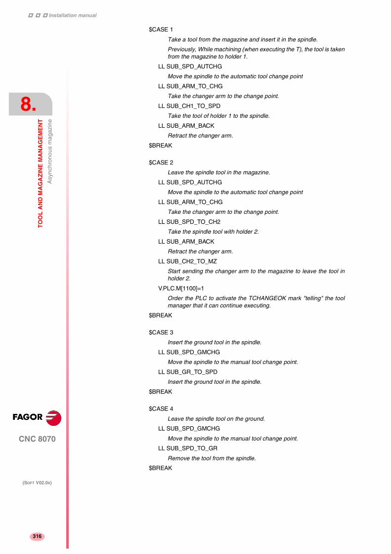
Installation manual
322
CNC 8070
8.
TO
OL
AN
D M
AG
AZ
INE
MA
NA
GE
ME
NT
Asy
nchr
onou
s m
agaz
ine
(SOFT V02.0X)
316
$CASE 1
Take a tool from the magazine and insert it in the spindle.
Previously, While machining (when executing the T), the tool is takenfrom the magazine to holder 1.
LL SUB_SPD_AUTCHG
Move the spindle to the automatic tool change point
LL SUB_ARM_TO_CHG
Take the changer arm to the change point.
LL SUB_CH1_TO_SPD
Take the tool of holder 1 to the spindle.
LL SUB_ARM_BACK
Retract the changer arm.
$BREAK
$CASE 2
Leave the spindle tool in the magazine.
LL SUB_SPD_AUTCHG
Move the spindle to the automatic tool change point
LL SUB_ARM_TO_CHG
Take the changer arm to the change point.
LL SUB_SPD_TO_CH2
Take the spindle tool with holder 2.
LL SUB_ARM_BACK
Retract the changer arm.
LL SUB_CH2_TO_MZ
Start sending the changer arm to the magazine to leave the tool inholder 2.
V.PLC.M[1100]=1
Order the PLC to activate the TCHANGEOK mark "telling" the toolmanager that it can continue executing.
$BREAK
$CASE 3
Insert the ground tool in the spindle.
LL SUB_SPD_GMCHG
Move the spindle to the manual tool change point.
LL SUB_GR_TO_SPD
Insert the ground tool in the spindle.
$BREAK
$CASE 4
Leave the spindle tool on the ground.
LL SUB_SPD_GMCHG
Move the spindle to the manual tool change point.
LL SUB_SPD_TO_GR
Remove the tool from the spindle.
$BREAK

Installation manual
CNC 8070
TO
OL
AN
D M
AG
AZ
INE
MA
NA
GE
ME
NT
Asy
nchr
onou
s m
agaz
ine
8.
(SOFT V02.0X)
317
$CASE 5
Leave the spindle tool in the magazine and take another one from themagazine.
Previously, While machining (when executing the T), the tool is takenfrom the magazine to holder 1.
LL SUB_SPD_AUTCHG
Move the spindle to the automatic tool change point
LL SUB_ARM_TO_CHG
Take the changer arm to the change point.
LL SUB_SPD_TO_CH2
Take the spindle tool with holder 2.
LL SUB_CH1_TO_SPD
Take the tool of holder 1 to the spindle.
LL SUB_ARM_BACK
Retract the changer arm.
LL SUB_CH2_TO_MZ
Start sending the changer arm to the magazine to leave the tool.
V.PLC.M[1100]=1
Order the PLC to activate the TCHANGEOK mark "telling" the toolmanager that it can continue executing.
$BREAK
$CASE 6
Leave the spindle tool in the magazine and take another one fromground.
LL SUB_SPD_AUTCHG
Move the spindle to the automatic tool change point
LL SUB_ARM_TO_CHG
Take the changer arm to the change point.
LL SUB_SPD_TO_CH2
Take the spindle tool with holder 2.
LL SUB_ARM_BACK
Retract the changer arm.
LL SUB_SPD_GMCHG
Move the spindle to the manual tool change point.
LL SUB_GR_TO_SPD
Insert the ground tool in the spindle.
LL SUB_CH2_TO_MZ
Start sending the changer arm to the magazine to leave the tool.
V.PLC.M[1100]=1
Order the PLC to activate the TCHANGEOK mark "telling" the toolmanager that it can continue executing.
$BREAK

Installation manual
322
CNC 8070
8.
TO
OL
AN
D M
AG
AZ
INE
MA
NA
GE
ME
NT
Asy
nchr
onou
s m
agaz
ine
(SOFT V02.0X)
318
$CASE 7
Leave the spindle tool on the ground and take another one from themagazine.
Previously, While machining (when executing the T), the tool is takenfrom the magazine to holder 1.
LL SUB_SPD_GMCHG
Move the spindle to the manual tool change point.
LL SUB_SPD_TO_GR
Remove the tool from the spindle.
LL SUB_SPD_AUTCHG
Move the spindle to the automatic tool change point
LL SUB_ARM_TO_CHG
Take the changer arm to the change point.
LL SUB_CH1_TO_SPD
Take the tool of holder 1 to the spindle.
LL SUB_ARM_BACK
Retract the changer arm.
$BREAK
$CASE 8
Leave the spindle tool on the ground and take another one fromground.
LL SUB_SPD_GMCHG
Move the spindle to the manual tool change point.
LL SUB_SPD_TO_GR
Remove the tool from the spindle.
LL SUB_GR_TO_SPD
Insert the ground tool in the spindle.
$BREAK
$CASE 9
Take a ground tool to the magazine going through the spindle.
LL SUB_SPD_GMCHG
Move the spindle to the manual tool change point.
LL SUB_GR_TO_SPD
Insert the ground tool in the spindle.
LL SUB_SPD_AUTCHG
Move the spindle to the automatic tool change point
LL SUB_ARM_TO_CHG
Take the changer arm to the change point.
LL SUB_SPD_TO_CH2
Take the spindle tool with holder 2.
LL SUB_ARM_BACK
Retract the changer arm.
LL SUB_CH2_TO_MZ
Start sending the changer arm to the magazine to leave the tool.
V.PLC.M[1100]=1
Order the PLC to activate the TCHANGEOK mark "telling" the toolmanager that it can continue executing.
$BREAK

Installation manual
CNC 8070
TO
OL
AN
D M
AG
AZ
INE
MA
NA
GE
ME
NT
Asy
nchr
onou
s m
agaz
ine
8.
(SOFT V02.0X)
319
$CASE 10
Take a tool from the magazine and leave on the ground going throughthe spindle.
LL SUB_MZ_TO_CH1
Take the tool from the magazine with holder 1.
LL SUB_SPD_AUTCHG
Move the spindle to the automatic tool change point
LL SUB_ARM_TO_CHG
Take the changer arm to the change point.
LL SUB_CH1_TO_SPD
Take the tool of holder 1 to the spindle.
LL SUB_ARM_BACK
Retract the changer arm.
LL SUB_SPD_GMCHG
Move the spindle to the manual tool change point.
LL SUB_SPD_TO_GR
Remove the tool from the spindle.
$BREAK
$ENDSWITCH
End of analysis of type of operation.
$WHILE V.TM.MZWAIT == 1$ENDWHILE
Wait for the tool manager.
#RET
End of M06 subroutine.

Installation manual
322
CNC 8070
8.
TO
OL
AN
D M
AG
AZ
INE
MA
NA
GE
ME
NT
Asy
nchr
onou
s m
agaz
ine
(SOFT V02.0X)
320
8.10.4 Basic PLC programming
When executing the -T- function
When executing the T function, the tool manager sends to the PLC thecode: TMOPERATION=11 to take the next tool in the arm and approachit to the spindle while machining.
DFU TMOPSTROBE AND CPS TMOPERATION EQ 11 = ···
The following operations must be carried out:
Send the changer arm to the magazine.
If LEAVEPOS indicates a magazine position, leave the tool of holder 1in that position and activate the CH1TOMZ mark.
Take the tool of the TAKEPOS position of the magazine with holder 1.Activate the MZTOCH1 mark to "tell" the tool manager that the tool hasbeen taken.
When executing the M06 function
When executing the M06 function, the tool manager sends to the PLC,in the TMOPERATION register, the code for the operation to be carriedout.
DFU TMOPSTROBE = MOV TMOPERATION R101
This instruction transfers the TMOPERATION value to register R101 soit is managed by the M06 subroutine.
Every time the M06 subroutine ends an action, it lets the PLC knowso it activates the relevant mark of the tool manager.
DFU M1100 = SET TCHANGEOK
DFD TCHANGEOK = RES M1100
Continue executing the program.
DFU M1101 = SET MZTOCH1
DFD MZTOCH1 = RES M1101
The tool has been taken from the magazine to holder 1.
DFU M1102 = SET CH1TOSPDL
DFD CH1TOSPDL = RES M1102
The tool has been taken from holder 1 to the spindle.
DFU M1104 = SET SPDLTOCH2
DFD SPDLTOCH2 = RES M1104
The tool has been taken from the spindle to holder 2.
DFU M1107 = SET SPDLTOGR
DFD SPDLTOGR = RES M1107
The tool has been taken from the spindle to ground.
DFU M1108 = SET GRTOSPDL
DFD GRTOSPDL = RES M1108
The tool has been taken from ground to the spindle.

Installation manual
CNC 8070
TO
OL
AN
D M
AG
AZ
INE
MA
NA
GE
ME
NT
Asy
nchr
onou
s m
agaz
ine
8.
(SOFT V02.0X)
321
The M06 subroutine uses the following M functions to "tell" the PLCwhich movements it must carry out.
Programming it depends on the type of machine. The auxiliaryfunctions will be completed after executing the requested movement.
Treatment of the M106 function:
• Completed when the changer arm exits the collision zone andmachining is possible.
• Activate the CH2TOMZ mark when the tool has been left to let thetool manager know that the tool has been taken from holder 2 tothe magazine".
Certain operations require using the information transferred by thetool manager in the following registers:
LEAVEPOS This register indicates the magazine position to leave thetool.
TAKEPOS This register indicates the magazine position of the toolto be taken (picked up).
Manager emergency signal
Treatment of the tool manager emergency signal.
DFU B11KEYBD1 = SET SETTMEM
Pressing the USER12 key activates the emergency.
TMINEM = B11KEYLED1
The lamp of the USER12 key turns on when there is an emergency.
TMINEM AND DFU B12KEYBD1 = SET RESTMEM
Pressing the USER13 key removes the emergency.
M101 Select in the magazine the position indicated by TAKEPOSand take the tool with holder 1.
M102 Take the tool of holder 1 to the spindle.
M104 Take the spindle tool with holder 2.
M106 Start sending the changer arm to the magazine to leave thetool in holder 2.
M121 Take the changer arm to the change point.
M122 Take the changer arm to the magazine.
M123 Retract the changer arm.

Installation manual
322
CNC 8070
8.
TO
OL
AN
D M
AG
AZ
INE
MA
NA
GE
ME
NT
Asy
nchr
onou
s m
agaz
ine
(SOFT V02.0X)
322

9
323
CNC 8070
(SOFT V02.0X)
CNC VARIABLES
9.1 Understanding the description of the variables
PRG / PLC / INT – Access to variables
The internal CNC variables may be accessed from the part program,MDI, PLC and from any application (for example FGUIM). This chapteruses the following abbreviations to indicate where these variablesmay be accessed from:
PRG From the part-program or MDI.
PLC from the PLC.
INT From any application (interface). For example FGUIM.
Each variable must indicate whether it can only be read (R) or readand written (R/W).
LIN / ROT / CAB / ANA / SER – Variables related to the axesand drives
For variables associated with the axes, they indicate the type of axisand the drive associated with the variable.
Lin Linear axis
Rot Rotary axis
Spd Spindle
Ana Analog drive
Ser Sercos drive.
When using Sercos drives, it will indicate whether the variable is validor not when the drive works in position mode (P) or velocity mode (S)or in both (P/S).

Installation manual
370
CNC 8070
9.
CN
C V
AR
IAB
LE
S
Und
erst
andi
ng th
e de
scrip
tion
of th
e va
riabl
es
(SOFT V02.0X)
324
EXEC – Access to the variable during preparation orexecution
The CNC reads several blocks ahead (preparation) of the one beingexecuted in order to calculate in advance the path to follow. This priorreading is known as "block preparation".
Certain variables are accessed during block preparation whereasothers are evaluated when they are executed. The latter interruptblock preparation.
(V.)G.PRGF Feedrate by program in G94. Evaluated duringpreparation (before executed).
(V.)G.FREAL Actual (real) CNC feedrate. Evaluated when beingexecuted.
For variables accessed from PRG, the "Exec" column indicateswhether the variable is read or written during block preparation orwhen being executed.
Yes When being executed. It interrupts block preparation.
No During preparation.
Accessing the variables from PLC or INT always interrupts blockpreparation.
Interrupting block preparation may result in compensated pathsdifferent from the ones programmed, undesired joints when workingwith small sections, interruptions when working with look-ahead, jerkyaxis movement, etc.
Use the #FLUSH instruction to force the evaluation of a variable whenit is being executed.
Sync / Asyn – Synchronous or asynchronous access fromthe PLC.
PLC access to the variable, both for reading and writing, may be eithersynchronous or asynchronous. A synchronous access is resolvedimmediately whereas an asynchronous access takes several PLCcycles to resolve.
The asynchronous variables are:
• The tool variables will be read asynchronously when the tool isneither the active one nor in the magazine.
• The tool variables will be written asynchronously whether the toolis the active one or not.
Example of how to access asynchronous variables
Reading of the radius value of offset ·1· of tool ·9· when it is notin the tool magazine.
<condition> AND NOT M11 = CNCRD (TM.TORT.[9][1], R11, M11)
The M11 mark is set to "1" at the beginning of the operation andit keeps its value until the end of the operation.
DFD M11 AND CPS R11 EQ 3 = ···
It waits for the consultation to end before evaluating the data.

Installation manual
CNC 8070
CN
C V
AR
IAB
LE
S
Und
erst
andi
ng th
e de
scrip
tion
of th
e va
riabl
es
9.
(SOFT V02.0X)
325
Examples of how to access synchronous variables:
<condition> = CNCRD (G.FREAL, R12, M12)
CPS R12 GT 2000 = ···
There is no need to wait for consulting the data because thesynchronous variables are resolved immediately.
<condition> = CNCWR (R13, PLC.TIMER, M13)
It resets the clock enabled by the PLC with the value containedin register R13.

Installation manual
370
CNC 8070
9.
CN
C V
AR
IAB
LE
S
Und
erst
andi
ng th
e de
scrip
tion
of th
e va
riabl
es
(SOFT V02.0X)
326
9.1.1 Access to numeric values from the PLC
When accessing from the PLC numeric values that may havedecimals, it must be borne in mind that the values are given as follows.
Coordinates
They will be given in ten-thousandths if they are in mm or hundred-thousandths if they are inches.
For 1 mm. the reading is 10000.
For 1 inch the reading is 100000.
For 1 degree the reading is 10000.
Feedrate of the axes
They will be given in ten-thousandths if they are in mm or hundred-thousandths if they are inches.
For 1 mm/min. the reading is 10000.
For 1 inch/min. the reading is 100000.
Spindle speed
They will be given in ten-thousandths.
With G97 for 1 rpm. the reading is 10000.
With G96, for 1 m/min. the reading is 10000.
With G96, for 1 foot/min. the reading is 10000.
With G196 for 1 rpm. the reading is 10000.
With M19, for 1 º/min. the reading is 10000.
Percentages
The real value will be given in tenths or in hundredths depending onthe variable. If not indicated otherwise, it will read the actual value. Ifnot so, it will indicate if the variable will be read in tenths (x10) or inhundredths (x100).
For 1% the reading is 1.
For 1% (x10) the reading is 10.
For 1% (x100) the reading is 100.
Time
They will be given in thousandths.
For 1 second the reading is 1000.
Voltage
The variables associated with the machine parameter table return theactual value (in millivolts). For the rest of the variables (in volts), thereading will appear in ten-thousandths.
For 1 Volt the reading is 10000.

Installation manual
CNC 8070
CN
C V
AR
IAB
LE
S
Und
erst
andi
ng th
e de
scrip
tion
of th
e va
riabl
es
9.
(SOFT V02.0X)
327
9.1.2 Accessing the variables in a single-channel system
Name of the variables
The generic mnemonic associated with the variables is written asfollows.
(V.){prefix}.{variable}
The mnemonic associated with each variable starts with a (V.). Usethese characters (except the parenthesis) when accessing from PRG;but do not use them when accessing from INT and PLC.
Axis and spindle parameters
Axis and spindle variables are identified with the prefix –A.–. Whenthese variables refer to a spindle, they may also be accessed with theprefix –SP.–.
(V.)A.{variable}.{axis/spindle}
(V.)SP.{variable}.{spindle}
The variables of the machine parameters with –MPA.– prefix can alsobe accessed using the –SP– prefix when referring to a spindle.
(V.)MPA.{variable}.{axis/spindle}
(V.)SP.{variable}.{spindle}
In these variables one must indicate which axis or spindle they referto. The axis may be referred to by its name or logic number; the spindlemay be referred to by its name, logic number or index in the spindlesystem.
Identifying the axes and the spindles.
In variables with the prefix –A.– and –MPA.–, the axes and the spindlesare identified with their logic number.
• For the axes, the logic number sets the order AXISNAME.
• For spindles, the logic number is given by the sum of NAXIS +orden SPDLNAME.
In variables with the prefix –SP.–, the spindles are identified with theirindex in the system, according to the order SPDLNAME.
Variables of the master spindle
They are special variables that may be used to access the data of themaster spindle without knowing its name or number. They are meantfor displaying data and programming cycles.
The variables are identified with the prefix –SP.– but without indicatingthe spindle.
Mnemonic PRG PLC / INT
(V.)MPG.NAXIS V.MPG.NAXIS MPG.NAXIS
(V.)SP.{var} Variable of the master spindle.

Installation manual
370
CNC 8070
9.
CN
C V
AR
IAB
LE
S
Und
erst
andi
ng th
e de
scrip
tion
of th
e va
riabl
es
(SOFT V02.0X)
328
Mnemonic Axis Spindle Master spindle
(V.)A.POS.Xn V.A.POS.X
V.A.POS.1
V.A.POS.S
V.SP.POS.SV.A.POS.6V.SP.POS.2
V.SP.POS
(V.)MPA.AXISTYPE.Xn V.MPA.AXISTYPE.XV.MPA.AXISTYPE.1
V.MPA.AXISTYPE.SV.SP.AXISTYPE.SV.MPA.AXISTYPE.6V.SP.AXISTYPE.2
V.SP.AXISTYPE

Installation manual
CNC 8070
CN
C V
AR
IAB
LE
S
Und
erst
andi
ng th
e de
scrip
tion
of th
e va
riabl
es
9.
(SOFT V02.0X)
329
9.1.3 Accessing the variables of a single-channel system
Name of the variables
The generic mnemonic associated with the variables is written asfollows.
(V.)[channel].{prefix}.{variable}
The mnemonic associated with each variable starts with a (V.). Usethese characters (except the parenthesis) when accessing from PRG;but do not use them when accessing from INT and PLC.
For these variables, you must indicate the channel they belong to (thefirst channel is number 1 and "0" is not a valid number). The bracketsmust be programmed.
Programming the channel is optional. If no channel is indicated, it willassume the following:
PRG Channel where it is being executed.
PLC First channel or main channel.
INT Active channel.
Axis and spindle parameters
Axis and spindle variables are identified with the prefix –A.–. Whenthese variables refer to a spindle, they may also be accessed with theprefix –SP.–.
(V.)[n].A.{variable}.{axis/spindle}
(V.)[n].SP.{variable}.{spindle}
The variables of the machine parameters with –MPA.– prefix can alsobe accessed using the –SP– prefix when referring to a spindle.
(V.)MPA.{variable}.{axis/spindle}
(V.)SP.{variable}.{spindle}
In these variables one must indicate which axis or spindle they referto. The axis may be referred to by its name or logic number; the spindlemay be referred to by its name, logic number or the spindle systemindex or channel index.
Mnemonic PRG PLC / INT
(V.)[n].G.FREAL V.[1].G.FREAL [1].G.FREAL

Installation manual
370
CNC 8070
9.
CN
C V
AR
IAB
LE
S
Und
erst
andi
ng th
e de
scrip
tion
of th
e va
riabl
es
(SOFT V02.0X)
330
Identifying the axes and the spindles.
In variables with the prefix –A.– and –MPA.–, the axes and the spindlesare identified with their logic number.
• For the axes, the logic number sets the order AXISNAME.
• For spindles, the logic number is given by the sum of NAXIS +orden SPDLNAME.
In variables with the prefix –SP.–, the spindles are identified with theirchannel index or with their system index.
• When reading from the program interface or PLC, the spindle isidentified with its system index according to the order SPDLNAME.
• When reading from the program interface (INT), the spindle isidentif ied with i ts channel index according to the orderCHSPDLNAME.
Access to common variables for axis and spindle
Accessing variables by their name
When referring to the axis or spindle by its name, programming thechannel they are in is not a determining factor; thus, programmingthem in this case is irrelevant. When programming the channel, if theaxis or spindle is not in it, its programming is ignored.
Accessing variables by their logic number
Depending on whether the channel number is programmed or not, themnemonic has a different meaning depending on whether it is accessfrom PRG, PLC or INT.
Accessing from PRG or PLC when not indicating the channel number.
Accessing from INT when not indicating the channel number.
Accessing from PRG, PLC or INT when indicating the channelnumber.
When indicating the channel number, the spindle variables cannot beaccessed using the –A.– prefix.
(V.)A.{var}.X Axis variable with that name.
(V.)A.{var}.S Spindle variable with that name.
(V.)SP.{var}.S2 Spindle variable with that name.
V.A.{var}.m Axis or spindle variable with logic number m.
V.SP.{var}.m Spindle variable with m index in the system.
A.{var}.m Axis variable with m index in the active channel.
SP.{var}.m Spindle variable with m index in the active channel.
(V.)[1].A.{var}.m Axis variable with m index in the channel.(n=1 corresponds to the first axis of thechannel)
(V.)[2].SP.{var}.m Spindle variable with m index in the channel.
(n=1 corresponds to the first spindle of thechannel)

Installation manual
CNC 8070
CN
C V
AR
IAB
LE
S
Und
erst
andi
ng th
e de
scrip
tion
of th
e va
riabl
es
9.
(SOFT V02.0X)
331
Accessing the exclusive spindle variables
Accessing variables by their name
The access and behavior are the same as if it were an axis and spindlevariable.
Accessing variables by their logic number
Depending on whether the channel number is programmed or not, themnemonic has a different meaning depending on whether it is accessfrom PRG, PLC or INT.
The access from PRG or PLC when not indicating the channel numberis the same as if it were an axis and spindle variable.
Accessing from INT when not indicating the channel number. Thespindle variables cannot be accessed from the interface using the–A.– prefix.
Accessing from PRG, PLC or INT when indicating the channelnumber. The spindle variables cannot be accessed using the –A.–prefix.
Variables of the master spindle
They are special variables that may be used to access the data of themaster spindle of each channel without knowing its name, logicnumber or index. They are meant for displaying data and programmingcycles.
The variables are identified with the prefix; but without indicating thenumber nor the name of the spindle.
If the channel is not programmed, it assumes the default channel,which in each is:
PRG Channel where it is being executed.
PLC First channel or main channel.
INT Active channel.
(V.)A.{var}.m Spindle variable with logic number m.
(V.)SP.{var}.m Spindle variable with m index in the system.
V.SP.{var}.m Spindle variable with m index in the activechannel.
(V.)[n].SP.{var}.m Spindle variable with m index in the n channel .
(V.)[n].SP.{var} Variable of the channel master spindle n.

Installation manual
370
CNC 8070
9.
CN
C V
AR
IAB
LE
S
Rel
ated
to g
ener
al m
achi
ne p
aram
eter
s
(SOFT V02.0X)
332
9.2 Related to general machine parameters
These variables are read-only (R) synchronous and are evaluated execution time.
They have generic names.
• Replace the "x" letter with the axis number.
• Replace the letters "i" and "m" with numbers keeping the brackets.
The PLC reading of TORQDIST, PRELOAD, TPROGAIN and TCOMPLIM comes in hundredths(x100). Ver "Access to numeric values from the PLC" en la página 326.
(V.)MPG.AXISNAMEx V.MPG.AXISNAME2 V.MPG.AXISNAME3
(V.)MPG.MASTERAXIS[i] V.MPG.MASTERAXIS[1] V.MPG.MASTERAXIS[2]
CHANNEL CONFIGURATION PRG PLC INT(V.)MPG.NCHANNEL Number of CNC channels. R R R
AXIS CONFIGURATION PRG PLC INT(V.)MPG.NAXIS Number of axes governed by the CNC R R R(V.)MPG.AXISNAMEx Name of the "n" logic axis — — R(V.)MPG.TMASTERAXIS[i] Tandem [i]. Logic number of the master axis R R R(V.)MPG.TSLAVEAXIS[i] Tandem [i]. Logic number of the slave axis R R R(V.)MPG.TORQDIST[i] Tandem [i]. Torque distribution R R R(V.)MPG.PRELOAD[i] Tandem [i]. Preload R R R(V.)MPG.PRELFITI[i] Tandem [i]. Time to apply the preload R R R(V.)MPG.TPROGAIN[i] Tandem [i]. Proportional gain R R R(V.)MPG.TINTIME[i] Tandem [i]. Integral gain R R R(V.)MPG.TCOMPLIM[i] Tandem [i]. Compensation Limit R R R(V.)MPG.MASTERAXIS[i] Gantry [i]. Logic number of the master axis R R R(V.)MPG.SLAVEAXIS[i] Gantry [i]. Logic number of the slave axis R R R(V.)MPG.WARNCOUPE[i] Gantry [i]. Maximum difference to issue a warning R R R(V.)MPG.MAXCOUPE[i] Gantry [i]. Maximum difference allowed R R R(V.)MPG.DIFFCOMP[i] Gantry [i]. Error difference compensation.
"0" = No "1"= YesR R R
SPINDLE CONFIGURATION PRG PLC INT(V.)MPG.NSPDL Number of spindles governed by the CNC R R R(V.)MPG.SPDLNAMEx Name of the "x" spindle — — R
TIME SETTING PRG PLC INT(V.)MPG.LOOPTIME Loop time R R R(V.)MPG.PRGFREQ Frequency of the PRG module (in cycles) R R R
CAN AND SERCOS BUS CONFIGURATION PRG PLC INT(V.)MPG.SERBRATE Sercos transmission speed
"0" = 4Mbps "1" = 2MbpsR R R
(V.)MPG.SERPOWSE Sercos optical power R R R(V.)MPG.CANLENGTH Can bus cable length (in meters)
"0" = Up to 20 "1" = Up to 30 "2" = Up to 40"3" = Up to 50 "4" = Up to 60 "5" = Up to 70"6" = Up to 80 "7" = Up to 90 "8" = Up to 100"9" >100
R R R
DEFAULT CONDITIONS PRG PLC INT(V.)MPG.INCHES Default work units
"0" = mm "1" = inchR R R

Installation manual
CNC 8070
CN
C V
AR
IAB
LE
S
Rel
ated
to g
ener
al m
achi
ne p
aram
eter
s
9.
(SOFT V02.0X)
333
RELATED TO ARITHMETIC PARAMETERS PRG PLC INT(V.)MPG.MAXLOCP Maximum local arithmetic parameter R R R(V.)MPG.MINLOCP Minimum local arithmetic parameter R R R(V.)MPG.MAXGLBP Maximum global arithmetic parameter R R R(V.)MPG.MINGLBP Minimum global arithmetic parameter R R R(V.)MPG.ROPARMAX Maximum global read-only arithmetic parameter R R R(V.)MPG.ROPARMIN Minimum global read-only arithmetic parameter R R R(V.)MPG.MAXCOMP Maximum common arithmetic parameter R R R(V.)MPG.MINCOMP Maximum common arithmetic parameter R R R
CROSS COMPENSATION TABLE PRG PLC INT(V.)MPG.MOVAXIS[m] Table [m]. Master axis R R R(V.)MPG.COMPAXIS[m] Table [m]. Axis to be compensated R R R(V.)MPG.NPCROSS[m] Table [m]. Number of points R R R(V.)MPG.TYPCROSS[m] Table [m]. Type of compensation
"0" = Real coordinates "1" = Theoretical coordinatesR R R
(V.)MPG.BIDIR[m] Table [m]. Bi-directional compensation"0" = No "1"= Yes
R R R
(V.)MPG.REFNEED[m] Table [m]. Mandatory home search"0" = No "1"= Yes
R R R
(V.)MPG.POSITION[m][i] Table [m]. Master axis position for point [i] R R R(V.)MPG.POSERROR[m][i] Table [m]. Error of point [i] in the positive direction R R R(V.)MPG.NEGERROR[m][i] Table [m]. Error of point [i] in the negative direction R R R
EXECUTION TIMES PRG PLC INT(V.)MPG.MINAENDW Minimum duration of the AUXEND signal R R R(V.)MPG.REFTIME Estimated home searching time R R R(V.)MPG.HTIME Estimated time for an "H" function R R R(V.)MPG.DTIME Estimated time for a "D" function R R R(V.)MPG.TTIME Estimated time for a "T" function R R R
NUMBERING OF DIGITAL I/O PRG PLC INT(V.)MPG.NDIMOD Total of digital input modules R R R(V.)MPG.NDOMOD Total of digital output modules R R R(V.)MPG.DIMODADDR[n] Base index of the digital input modules R R R(V.)MPG.DOMODADDR[n] Base index of the digital output modules R R R
PROBE PRG PLC INT(V.)MPG.PROBE There is a probe for tool calibration
"0" = No "1"= YesR R R
(V.)MPG.PRBDI1 Digital input associated with probe 1 R R R(V.)MPG.PRBDI2 Digital input associated with probe 2 R R R(V.)MPG.PRBPULSE1 Type of pulse of probe 1
"0" = Negative "1" = PositiveR R R
(V.)MPG.PRBPULSE2 Type of pulse of probe 2"0" = Negative "1" = Positive
R R R

Installation manual
370
CNC 8070
9.
CN
C V
AR
IAB
LE
S
Rel
ated
to g
ener
al m
achi
ne p
aram
eter
s
(SOFT V02.0X)
334
9.2.1 Channel related
These variables are read-only (R) synchronous and are evaluated execution time.
They have generic names.
• Replace the "n" character with the channel number, maintaining the brackets. The firstchannel is identified with the number 1, "0" is not a valid number.
• Replace the "x" letter with the axis number.
PLC reading of CIRINFACT and MAXOVR comes in tenths (a reading of 10 for 1%) Ver "Access tonumeric values from the PLC" en la página 326.
(V.)[n].MPG.GROUPID V.[1].MPG.GROUPID V.[2].MPG.GRUOPID
(V.)[n].MPG.CHAXISNAMEx V.[2].MPG.CHAXISNAME2 V.[1].MPG.CHAXISNAME3
CHANNEL CONFIGURATION PRG PLC INT(V.)[n].MPG.GROUPID Group the channel belongs to R R R(V.)[n].MPG.CHTYPE Channel type
"0" = CNC "1" = PLC "2" = CNC+PLCR R R
(V.)[n].MPG.HIDDENCH Hidden channel"0" = No "1"= Yes
R R R
CONFIGURING THE AXES OF THE CHANNEL PRG PLC INT(V.)[n].MPG.CHNAXIS Number of axes of the channel R R R(V.)[n].MPG.CHAXISNAMEx Name of the "n" logic axis — — R
CONFIGURING THE SPINDLES OF THE CHANNEL PRG PLC INT(V.)[n].MPG.CHNSPDL Number of spindles of the channel R R R(V.)[n].MPG.CHSPDLNAMEx Name of the "x" spindle — — R(V.)[n].MPG.CAXNAME Axis working as "C" axis (by default) — — R(V.)[n].MPG.ALIGNC "C" axis in diametrical machining
"0" = No "1"= YesR R R
TIME SETTING (CHANNEL) PRG PLC INT(V.)[n].MPG.PREPFREQ Number of blocks to prepare per cycle R R R(V.)[n].MPG.ANTIME Anticipation time R R R
DEFAULT CONDITIONS PRG PLC INT(V.)[n].MPG.KINID Default kinematics number R R R(V.)[n].MPG.SLOPETYPE Default acceleration type
"1" = Linear "2" = Trapezoidal "3" = Square sineR R R
(V.)[n].MPG.IPLANE Default work plane"0" = G17 "1" = G18
R R R
(V.)[n].MPG.ISYSTEM Default programming type"0" = G90 "1" = G91
R R R
(V.)[n].MPG.IMOVE Default movement type"0" = G00 "1" = G01
R R R
(V.)[n].MPG.IFEED Default feedrate type"0" = G94 "1" = G95
R R R
(V.)[n].MPG.ICORNER Default corner type"0" = G50 "1" = G05 "2" = G07
R R R
(V.)[n].MPG.IRCOMP Radius compensation mode by default"0" = G136 "1" = G137
R R R
(V.)[n].MPG.ROUNDTYPE Rounding type in G5 (by default)"0" = Chordal error "1" = %feedrate
R R R
(V.)[n].MPG.MAXROUND Maximum rounding error in G5 R R R(V.)[n].MPG.ROUNDFEED Percentage of feedrate in G5 R R R(V.)[n].MPG.CIRINERR Absolute radius error R R R(V.)[n].MPG.CIRINFACT Percentage of error over the radius R R R(V.)[n].MPG.MAXOVR Maximum axis override (%) R R R(V.)[n].MPG.RAPIDOVR Override affecting G00
"0" = No "1"= YesR R R

Installation manual
CNC 8070
CN
C V
AR
IAB
LE
S
Rel
ated
to g
ener
al m
achi
ne p
aram
eter
s
9.
(SOFT V02.0X)
335
RELATED TO SUBROUTINES PRG PLC INT(V.)[n].MPG.TOOLSUB Subroutine associated with "T" — — R(V.)[n].MPG.REFPSUB Subroutine associated with G74 — — R(V.)[n].MPG.OEMSUB(1..10) Subroutines associated with G180 through G189 — — R(V.)[n].MPG.SUBPATH Program subroutine path — — R
PROBE PRG PLC INT(V.)[n].MPG.PRB1MIN Minimum probe coordinate along the abscissa axis R R R(V.)[n].MPG.PRB1MAX Maximum probe coordinate along the abscissa axis R R R(V.)[n].MPG.PRB2MIN Minimum probe coordinate along the ordinate axis R R R(V.)[n].MPG.PRB2MAX Maximum probe coordinate along the ordinate axis R R R(V.)[n].MPG.PRB3MIN Minimum probe coordinate along the axis
perpendicular to the planeR R R
(V.)[n].MPG.PRB3MAX Maximum probe coordinate along the axis perpendicular to the plane
R R R

Installation manual
370
CNC 8070
9.
CN
C V
AR
IAB
LE
S
Rel
ated
to a
xis
mac
hine
par
amet
ers
(SOFT V02.0X)
336
9.3 Related to axis machine parameters
When these variables refer to a spindle, they may be accessed using prefix –MPA.– or –SP.–indistinctly.
These variables may be accessed from the program (PRG), PLC and interface (INT), they areread-only (R) synchronous and are evaluated in execution time.
They have generic names.
• Replace the "n" character with the channel number, maintaining the brackets. The firstchannel is identified with the number 1, "0" is not a valid number.
• Replace the "Xn" character by the name, logic number or index in the channel of the axis orof the spindle.
• Replace the letter "i" with a number keeping the brackets.
(V.)[n].MPA.AXISTYPE.Xn V.[1].MPA.AXISTYPE.XV.SP.AXISTYPE.S
V.[2].MPA.AXISTYPE.1V.[3].SP.AXISTYPE.6
(V.)[n].MPA.INCJOGDIST[i].Xn V.[2].MPA.INCJOGDIST[1].Z V.[4].MPA.INCJOGDIST[2].3
BELONGING TO THE CHANNEL Lin Rot Spd Ana Ser(V.)[n].MPA.AXISEXCH Channel change permission
"0" = No "1" = Temporary "2" = MaintainedYes Yes Yes Yes P/S
TYPE OF AXIS AND DRIVE Lin Rot Spd Ana Ser(V.)[n].MPA.DRIVETYPE.Xn Type of drive
"1" = Analog "2" = Sercos "16"=SimulatedYes Yes Yes Yes P/S
(V.)[n].MPA.AXISTYPE.Xn Type of axis"1" = Linear "2" = Rotary "4" = Spindle
Yes Yes Yes Yes P/S
(V.)[n].MPA.DRIVEID.Xn Sercos drive select (ID) Yes Yes Yes — P/S(V.)[n].MPA.OPMODEP.Xn Sercos drive operating mode
"0" = Position "1" = VelocityYes Yes Yes — P/S
(V.)[n].MPA.FBACKSRC.Xn Type of axis"0" = Internal "1" = External
Yes Yes Yes — P/S
HIRTH AXIS Lin Rot Spd Ana Ser(V.)[n].MPA.HIRTH.Xn Hirth axis
"0" = No "1"= YesYes Yes — Yes P/S
(V.)[n].MPA.HPITCH.Xn Hirth axis pitch Yes Yes — Yes P/S
AXIS CONFIGURATION FOR LATHE TYPE MACHINES Lin Rot Spd Ana Ser(V.)[n].MPA.FACEAXIS.Xn Face axis
"0" = No "1"= YesYes — — Yes P/S
(V.)[n].MPA.LONGAXIS.Xn Longitudinal axis"0" = No "1"= Yes
Yes — — Yes P/S
ROTARY AXES Lin Rot Spd Ana Ser(V.)[n].MPA.AXISMODE.Xn Work mode
"0" = Module "1" = Linear like— Yes — Yes P/S
(V.)[n].MPA.UNIDIR.Xn Unidirectional rotation"0" = No "1"= Yes
— Yes — Yes P/S
(V.)[n].MPA.SHORTESTWAY.Xn Via shortest way"0" = No "1"= Yes
— Yes — Yes P/S
ROTARY AXES AND SPINDLE Lin Rot Spd Ana Ser(V.)[n].MPA.MODCOMP.Xn Module compensation
"0" = No "1"= Yes— Yes Yes Yes S
(V.)[n].MPA.CAXIS.Xn Works as a "C" axis"0" = No "1"= Yes
— Yes Yes Yes P/S
(V.)[n].MPA.CAXSET.Xn Work set for "C" axis — Yes Yes Yes P/S

Installation manual
CNC 8070
CN
C V
AR
IAB
LE
S
Rel
ated
to a
xis
mac
hine
par
amet
ers
9.
(SOFT V02.0X)
337
PLC reading of LOSPDLIM, UPSPDLIM, STEPOVR, MINOVR and MAXOVR comes in tenths (areading of 10 for 1%) Ver "Access to numeric values from the PLC" en la página 326.
SPINDLE Lin Rot Spd Ana Ser(V.)[n].MPA.AUTOGEAR.Xn Automatic gear change
"0" = No "1"= Yes— — Yes Yes P/S
(V.)[n].MPA.LOSPDLIM.Xn Lower "rpm OK" percentage — — Yes Yes P/S(V.)[n].MPA.UPSPDLIM.Xn Upper "rpm OK" percentage — — Yes Yes P/S(V.)[n].MPA.SPDLTIME.Xn Estimated time for an S function — — Yes Yes P/S(V.)[n].MPA.SPDLSTOP.Xn M2, M30 and Reset stop the spindle
"0" = No "1"= Yes— — Yes Yes P/S
(V.)[n].MPA.SREVM05.Xn G84. Reversal stops the spindle"0" = No "1"= Yes
— — Yes Yes P/S
(V.)[n].MPA.STEPOVR.Xn Override step — — Yes Yes P/S(V.)[n].MPA.MINOVR.Xn Minimum override (%) — — Yes Yes P/S(V.)[n].MPA.MAXOVR.Xn Maximum override (%) — — Yes Yes P/S
SOFTWARE AXIS LIMITS Lin Rot Spd Ana Ser(V.)[n].MPA.POSLIMIT.Xn Positive software limit Yes Yes — Yes P/S(V.)[n].MPA.NEGLIMIT.Xn Negative software limit Yes Yes — Yes P/S(V.)[n].MPA.SWLIMITTOL.Xn Software limit tolerance Yes Yes — Yes P/S
RUNAWAY PROTECTION Lin Rot Spd Ana Ser(V.)[n].MPA.TENDENCY.Xn Activation of tendency test
"0" = No "1"= YesYes Yes Yes Yes P/S
PLC OFFSET Lin Rot Spd Ana Ser(V.)[n].MPA.PLCOINC.Xn PLC offset increment per cycle Yes Yes Yes Yes P/S
DWELL FOR DEAD AXES Lin Rot Spd Ana Ser(V.)[n].MPA.DWELL.Xn Dwell for dead axes Yes Yes Yes Yes P/S
RADIUS / DIAMETER Lin Rot Spd Ana Ser(V.)[n].MPA.DIAMPROG.Xn Programming in diameters
"0" = No "1"= YesYes — — Yes P/S
HOME SEARCH Lin Rot Spd Ana Ser(V.)[n].MPA.REFDIREC.Xn Home search direction
"0" = Negative "1" = PositiveYes Yes Yes Yes P/S
(V.)[n].MPA.DECINPUT.Xn Home switch"0" = No "1"= Yes
Yes Yes Yes Yes P/S
PROBE Lin Rot Spd Ana Ser(V.)[n].MPA.PROBEAXIS.Xn Probing axis Yes Yes — Yes P/S(V.)[n].MPA.PROBERANGE.Xn Maximum braking distance Yes Yes — Yes P/S(V.)[n].MPA.PROBEFEED.Xn Probing feedrate Yes Yes — Yes P/S(V.)[n].MPA.PROBEDELAY Delay for the "probe 1" signal Yes Yes — Yes P/S(V.)[n].MPA.PROBEDELAY Delay for the "probe 2" signal Yes Yes — Yes P/S
TOOL INSPECTION Lin Rot Spd Ana Ser(V.)[n].MPA.REPOSFEED.Xn Maximum repositioning feedrate Yes Yes — Yes P/S
INDEPENDENT AXIS Lin Rot Spd Ana Ser(V.)[n].MPA.POSFEED.Xn Positioning feedrate Yes Yes Yes Yes P/S(V.)[n].MPA.DSYNCVELW.Xn Velocity synchronization window Yes Yes Yes Yes P/S(V.)[n].MPA.DSYNCPOSW.Xn Position synchronization window Yes Yes Yes Yes P/S

Installation manual
370
CNC 8070
9.
CN
C V
AR
IAB
LE
S
Rel
ated
to a
xis
mac
hine
par
amet
ers
(SOFT V02.0X)
338
JOG MODELinRot
Spd Ana Ser
(V.)[n].MPA.MANPOSSW.Xn Maximum positive travel with G201 Yes — Yes P/S(V.)[n].MPA.MANNEGSW.Xn Maximum negative travel with G201 Yes — Yes P/S(V.)[n].MPA.JOGFEED.Xn Continuous JOG mode feedrate Yes — Yes P/S(V.)[n].MPA.JOGRAPFEED.Xn Rapid feed in continuous JOG mode Yes — Yes P/S(V.)[n].MPA.MAXMANFEED.Xn Maximum feed in continuous JOG Yes — Yes P/S(V.)[n].MPA.MAXMANACC.Xn Maximum acceleration in JOG mode Yes — Yes P/S(V.)[n].MPA.MANFEEDP.Xn Maximum % of jog feedrate with G201 Yes — Yes P/S(V.)[n].MPA.IPOFEEDP.Xn Maximum % of execution feedrate with G201 Yes — Yes P/S(V.)[n].MPA.MANACCP.Xn Maximum % of jog acceleration with G201 Yes — Yes P/S(V.)[n].MPA.IPOACCP.Xn Maximum % of execution acceleration with G201 Yes — Yes P/S
JOG MODE. HANDWHEELS Lin Rot Spd Ana Ser(V.)[n].MPA.MPGRESOL[i].Xn Dial resolution at the [i] position Yes Yes — Yes P/S(V.)[n].MPA.MPGFILTER.Xn Filter time for the handwheel Yes Yes — Yes P/S
JOG MODE. INCREMENTAL JOG Lin Rot Spd Ana Ser(V.)[n].MPA.INCJOGDIST[i].Xn Moving distance at [i] dial position Yes Yes — Yes P/S(V.)[n].MPA.INCJOGFEED[i].Xn Feedrate at [i] position Yes Yes — Yes P/S
LEADSCREW ERROR COMPENSATION Lin Rot Spd Ana Ser(V.)[n].MPA.LSCRWCOMP.Xn Leadscrew error compensation
"0" = No "1"= YesYes Yes Yes Yes P/S
(V.)[n].MPA.NPOINTS.Xn Number of points in the table Yes Yes Yes Yes P/S(V.)[n].MPA.TYPLSCRW.Xn Type of compensation
"0" = Real coordinates "1" = Theoretical coordinates
Yes Yes Yes Yes P/S
(V.)[n].MPA.BIDIR.Xn Bi-directional compensation"0" = No "1"= Yes
Yes Yes Yes Yes P/S
(V.)[n].MPA.REFNEED.Xn Mandatory home search"0" = No "1"= Yes
Yes Yes Yes Yes P/S
(V.)[n].MPA.POSITION[i].Xn Master axis position for point [i] Yes Yes Yes Yes P/S(V.)[n].MPA.POSERROR[i].Xn Error of point [i] in the positive direction Yes Yes Yes Yes P/S(V.)[n].MPA.NEGERROR[i].Xn Error of point [i] in the negative direction Yes Yes Yes Yes P/S
FILTERS Lin Rot Spd Ana Ser(V.)[n].MPA.ORDER[i].Xn Filter order Yes Yes Yes Yes P/S(V.)[n].MPA.TYPE[i].Xn Type of filter
"1" = Low passing "2" = Anti-resonanceYes Yes Yes Yes P/S
(V.)[n].MPA.FREQUENCY[i].Xn Break or center frequency Yes Yes Yes Yes P/S(V.)[n].MPA.NORBWIDTH[i].Xn Normal bandwidth Yes Yes Yes Yes P/S(V.)[n].MPA.SHARE[i].Xn % of signal going through the filter Yes Yes Yes Yes P/S
WORK SETS Lin Rot Spd Ana Ser(V.)[n].MPA.NPARSETS.Xn Number of work sets Yes Yes Yes Yes P/S(V.)[n].MPA.DEFAULTSET.Xn Default work set (on power-up) Yes Yes Yes Yes P/S

Installation manual
CNC 8070
CN
C V
AR
IAB
LE
S
Rel
ated
to a
xis
mac
hine
par
amet
ers
9.
(SOFT V02.0X)
339
9.3.1 Related to gear parameters
These variables may be accessed from the program (PRG), PLC and interface (INT), they areread-only (R) synchronous and are evaluated in execution time.
They have generic names.
• Replace the "n" character with the channel number, maintaining the brackets. The firstchannel is identified with the number 1, "0" is not a valid number.
• Replace the letter "g" with a gear number keeping the brackets. The first gear is identifiedwith the number 1, "0" is not a valid number.
• Replace the "Xn" character by the name, logic number or index in the channel of the axis orof the spindle.
(V.)[n].MPA.COUNTERID[g].Xn V.[1].MPA.COUNTERID[1].X V.[2].MPA.COUNTERID[2].1
(V.)[n].MPA.PITCH[g].Xn V.[2].MPA.PITCH[1].Z V.[4].MPA.PITCH[2].3
RESOLUTIONLinRot
Spd Ana Ser
(V.)[n].MPA.PITCH[g].Xn Leadscrew pitch Yes Yes Yes P/S(V.)[n].MPA.PITCH2[g].Xn Leadscrew pitch (2nd feedback) Yes Yes — P/S(V.)[n].MPA.NPULSES[g].Xn Number of encoder pulses Yes Yes Yes S(V.)[n].MPA.NPULSES2[g].Xn Number of encoder pulses (2nd feedback) Yes Yes Yes S(V.)[n].MPA.INPUTREV[g].Xn Turns of the motor shaft Yes Yes Yes P/S(V.)[n].MPA.INPUTREV2[g].Xn Turns of the motor shaft (2nd feedback) Yes Yes — P/S(V.)[n].MPA.OUTPUTREV[g].Xn Turns of the machine axis Yes Yes Yes P/S(V.)[n].MPA.OUTPUTREV2[g].Xn Turns of the machine axis (2nd feedback) Yes Yes — P/S(V.)[n].MPA.SINMAGNI[g].Xn Sinusoidal multiplying factor Yes Yes Yes —(V.)[n].MPA.ABSFEEDBACK[g].Xn Absolute feedback system
"0" = No "1"= YesYes Yes Yes P/S
(V.)[n].MPA.FBACKAL[g] Feedback alarm activation"0" = No "1"= Yes
Yes Yes Yes —
LOOP SETTING Lin Rot Spd Ana Ser(V.)[n].MPA.LOOPCH[g].Xn Analog voltage sign change
"0" = No "1"= YesYes Yes Yes Yes P/S
(V.)[n].MPA.AXISCH[g].Xn Feedback sign change"0" = No "1"= Yes
Yes Yes Yes Yes P/S
(V.)[n].MPA.INPOSW[g].Xn In-position zone Yes Yes Yes Yes P/S
BACKLASH IN MOVEMENT REVERSAL Lin Rot Spd Ana Ser(V.)[n].MPA.BACKLASH[g].Xn Backlash Yes Yes Yes Yes P/S
BACKLASH. ADDITIONAL VELOCITY COMMAND PULSE Lin Rot Spd Ana Ser(V.)[n].MPA.BAKANOUT[g].Xn Additional velocity command pulse Yes Yes Yes Yes P/S(V.)[n].MPA.BAKTIME[g].Xn Duration of the additional velocity command
pulseYes Yes Yes Yes P/S
(V.)[n].MPA.ACTBAKAN[g].Xn Application of the additional velocity command pulse
"0" = G2/G3 "1" = Always
Yes Yes Yes Yes P/S
FEEDRATE SETTING Lin Rot Spd Ana Ser(V.)[n].MPA.G00FEED[g].Xn Feedrate in G00 Yes Yes Yes Yes P/S(V.)[n].MPA.MAXVOLT[g].Xn Analog voltage for G00FEED Yes Yes Yes Yes S

Installation manual
370
CNC 8070
9.
CN
C V
AR
IAB
LE
S
Rel
ated
to a
xis
mac
hine
par
amet
ers
(SOFT V02.0X)
340
The PLC reading of ACFGAIN and MANACFGAIN comes in tenths (x10) The PLC reading of FFGAINand MANFFGAIN comes in hundredths (x100) Ver "Access to numeric values from the PLC" enla página 326.
GAIN SETTING Lin Rot Spd Ana Ser(V.)[n].MPA.PROGAIN[g].Xn Proportional gain Yes Yes Yes Yes P/S(V.)[n].MPA.FFWTYPE[g].Xn Pre-control (feed-forward) type
"0" = Off"1" = Feed-forward"2" = Ac-forward"3" = Feed-forward + Ac-forward
Yes Yes Yes Yes P/S
(V.)[n].MPA.FFGAIN[g].Xn Percentage of Feed-Forward in automatic Yes Yes Yes Yes P/S(V.)[n].MPA.MANFFGAIN[g].Xn Percentage of Feed-Forward in JOG Yes Yes — Yes P/S(V.)[n].MPA.ACFWFACTOR[g].Xn Acceleration time constant Yes Yes Yes Yes S(V.)[n].MPA.ACFGAIN[g].Xn Percentage AC-Forward in automatic Yes Yes Yes Yes P/S(V.)[n].MPA.MANACFGAIN[g].Xn Percentage of AC-Forward in JOG Yes Yes — Yes P/S
Although in the machine parameter table they may be read with up to four decimals, the following variableswill only be read with one or two decimals whichever the case may be.
• In variables ACFGAIN and MANACFGAIN , only the first decimal is relevant.
• In variables FFGAIN and MANFFGAIN only the first two decimals are relevant.
LINEAR ACCELERATION Lin Rot Spd Ana Ser(V.)[n].MPA.LACC1[g].Xn Acceleration of the first section Yes Yes Yes Yes P/S(V.)[n].MPA.LACC2[g].Xn Acceleration of the second section Yes Yes Yes Yes P/S(V.)[n].MPA.LFEED[g].Xn Change speed Yes Yes Yes Yes P/S
TRAPEZOIDAL AND SQUARE SINE ACCELERATION Lin Rot Spd Ana Ser(V.)[n].MPA.ACCEL[g].Xn Acceleration Yes Yes Yes Yes P/S(V.)[n].MPA.DECEL[g].Xn Deceleration Yes Yes Yes Yes P/S(V.)[n].MPA.ACCJERK[g].Xn Acceleration Jerk Yes Yes Yes Yes P/S(V.)[n].MPA.DECJERK[g].Xn Deceleration Jerk Yes Yes Yes Yes P/S
HOME SEARCH Lin Rot Spd Ana Ser(V.)[n].MPA.I0TYPE[g].Xn Reference mark (I0) type
"0" = Normal"1" = Increasing distance coded"2" = Decreasing distance coded
Yes Yes Yes Yes P/S
(V.)[n].MPA.REFVALUE[g].Xn Home position Yes Yes Yes Yes P/S(V.)[n].MPA.REFSHIFT[g].Xn Offset of the reference point (home) Yes Yes Yes Yes P/S(V.)[n].MPA.REFFEED1[g].Xn Fast home searching feedrate Yes Yes Yes Yes P/S(V.)[n].MPA.REFFEED2[g].Xn Slow home searching feedrate Yes Yes Yes Yes P/S(V.)[n].MPA.REFPULSE[g].Xn Type of I0 pulse
"0" = Negative "1" = PositiveYes Yes Yes Yes P/S
(V.)[n].MPA.ABSOFF[g].Xn Offset with respect to coded ref. mark Yes Yes Yes Yes P/S(V.)[n].MPA.EXTMULT[g].Xn External factor for distance-coded mark Yes Yes Yes Yes —(V.)[n].MPA.I0CODDI1[g].Xn Pitch between 2 fixed coded marks Yes Yes Yes Yes P/S(V.)[n].MPA.I0CODDI2[g].Xn Pitch between 2 variable coded marks Yes Yes Yes Yes P/S
FOLLOWING ERROR Lin Rot Spd Ana Ser(V.)[n].MPA.FLWEMONITOR[g].Xn Monitoring type
"0" = Off "1" = Standard "2" = LinearYes Yes Yes Yes P/S
(V.)[n].MPA.MINFLWE[g].Xn Maximum following error when stopped Yes Yes Yes Yes P/S(V.)[n].MPA.MAXFLWE[g].Xn Maximum following error when moving Yes Yes Yes Yes P/S(V.)[n].MPA.FEDYNFAC[g].Xn % of following error deviation Yes Yes Yes Yes P/S(V.)[n].MPA.ESTDELAY[g].Xn Following error delay Yes Yes Yes Yes P/S(V.)[n].MPA.INPOMAX[g].Xn Time to get in position Yes Yes Yes Yes P/S(V.)[n].MPA.INPOTIME[g].Xn Minimum time to stay in position Yes Yes Yes Yes P/S
AXIS LUBRICATION Lin Rot Spd Ana Ser(V.)[n].MPA.DISTLUBRI[g].Xn Distance for lubrication pulse Yes Yes Yes Yes P/S

Installation manual
CNC 8070
CN
C V
AR
IAB
LE
S
Rel
ated
to a
xis
mac
hine
par
amet
ers
9.
(SOFT V02.0X)
341
ROTARY AXES AND SPINDLE Lin Rot Spd Ana Ser(V.)[n].MPA.MODUPLIM[g].Xn Module's upper limit — Yes Yes Yes S(V.)[n].MPA.MODLOWLIM[g].Xn Module's lower limit — Yes Yes Yes S(V.)[n].MPA.MODNROT[g].Xn Module error. Number of turns — Yes Yes Yes S(V.)[n].MPA.MODERR[g].Xn Module error. Number of increments — Yes Yes Yes S
SPINDLE Lin Rot Spd Ana Ser(V.)[n].MPA.SZERO[g].Xn Speed considered "0 rpm" — — Yes — P/S(V.)[n].MPA.POLARM3[g].Xn Analog voltage sign M3
"0" = Negative "1" = Positive— — Yes — S
(V.)[n].MPA.POLARM4[g].Xn Analog voltage sign M4"0" = Negative "1" = Positive
— — Yes — S
ANALOG VOLTAGE Lin Rot Spd Ana Ser(V.)[n].MPA.SERVOOFF[g].Xn Offset compensation Yes Yes Yes Yes —(V.)[n].MPA.MINANOUT[g].Xn Minimum analog output Yes Yes Yes Yes —
ANALOG OUTPUT / FEEDBACK INPUT Lin Rot Spd Ana Ser(V.)[n].MPA.ANAOUTID[g].Xn Analog output of the axis Yes Yes Yes Yes —(V.)[n].MPA.COUNTERID[g].Xn Feedback input for the axis Yes Yes Yes Yes —

Installation manual
370
CNC 8070
9.
CN
C V
AR
IAB
LE
S
Rel
ated
to jo
g m
ode
para
met
ers
(SOFT V02.0X)
342
9.4 Related to jog mode parameters
These variables are read-only (R) synchronous and are evaluated execution time.
They have generic names.
• Replace the letter "i" with the number keeping the brackets.
(V.)MPMAN.NMPG V.MPMAN.NMPG
(V.)MPMAN.MPGAXIS[i] V.MPMAN.MPGAXIS[1] V.MPMAN.MPGAXIS[2]
HANDWHEELS PRG PLC INT(V.)MPMAN.NMPG Number of handwheels R R R(V.)MPMAN.COUNTERID[i] Feedback input for the handwheel [i] R R R(V.)MPMAN.MPGAXIS[i] Axis associated with handwheel [i] R R R
JOG KEYS PRG PLC INT(V.)MPMAN.JOGKEYDEF[i] Axis and moving direction of the JOG [i] key R R R(V.)MPMAN.JOGTYPE JOG behavior R R R
This variable may have the following values:
"1", "2"..."16" = Machine parameter set to "+1", "+2"..."+16". (Key for the axis and positive direction)
"-1", "-2"... "-16" = Machine parameter set to "-1", "-2"..."-16". (Key for the axis and negative direction)
"101", "102"..."116" = Machine parameter set to "1", "2"..."16". (Axis key)
"300" = Machine parameter set to "R". (Rapid key)
"301" = Machine parameter set to "+". (Key for positive direction)
"302" = Machine parameter set to "-". (Key for negative direction)

Installation manual
CNC 8070
CN
C V
AR
IAB
LE
S
Rel
ated
to "
M"
func
tion
para
met
ers
9.
(SOFT V02.0X)
343
9.5 Related to "M" function parameters
These variables are read-only (R) synchronous and are evaluated execution time.
They have generic names.
• Replace the letter "i" with the number keeping the brackets.
(V.)MPM.MNUM[i] V.MPM.MNUM[3]
(V.)MPM.MTABLESIZE V.MPM.MTABLESIZE
"M" FUNCTION TABLE PRG PLC INT(V.)MPM.MTABLESIZE Number of elements of the "M" function table R R R(V.)MPM.MNUM[i] "M" function number R R R(V.)MPM.SYNCHTYPE[i] Type of synchronism of the "M" function
"0" = Without synchronism "2" = Before-before"4" = Before-after "8" = after-after
R R R
(V.)MPM.MTIME[i] Estimated time for an "M" function R R R(V.)MPM.MPROGNAME[i] Name of the subroutine associated with the "M"
function— — R

Installation manual
370
CNC 8070
9.
CN
C V
AR
IAB
LE
S
Rel
ated
to k
inem
atic
par
amet
ers
(SOFT V02.0X)
344
9.6 Related to kinematic parameters
These variables are read-only (R) synchronous and are evaluated execution time.
They have generic names.
• Replace the "n" letter with the kinematics number.
• Replace the "m" letter with the offset number.
(V.)MPK.KINn[m] V.MPK.KIN1[1] V.MPK.KIN6[42]
KINEMATICS PRG PLC INT(V.)MPK.NKIN Kinematics table R R R(V.)MPK.TYPE Kinetics type R R R(V.)MPK.KINn[m] [m] offset of "n" kinematics R R R

Installation manual
CNC 8070
CN
C V
AR
IAB
LE
S
Rel
ated
to m
agaz
ine
para
met
ers
9.
(SOFT V02.0X)
345
9.7 Related to magazine parameters
These variables are read-only (R) synchronous and are evaluated execution time.
They have generic names.
• Replace the "z" character with the magazine number, maintaining the brackets.
(V.)TM.MZSIZE[z] V.TM.MZSIZE[1]
MAGAZINE PRG PLC INT(V.)TM.NTOOLMZ Number of tool magazines R R R(V.)TM.MZGROUND[z] Ground tools allowed
"0" = No "1"= YesR R R
(V.)TM.MZSIZE[z] Magazine size R R R(V.)TM.MZRANDOM[z] Random magazine
"0" = No "1"= YesR R R
(V.)TM.MZTYPE[z] Type of magazine"1" = Asynchronous"2" = Synchronous"3" = Turret"4" = Synchronous with 1 arm"5" = Synchronous with 2 arms
R R R
(V.)TM.MZCYCLIC[z] Cyclic tool changer"0" = No "1"= Yes
R R R
(V.)TM.MZOPTIMIZED[z] Tool management"0" = No "1"= Yes
R R R
(V.)TM.MZM6ALONE[z] Action when executing an M6 without a tool"0" = Nothing "1" = Warning "2" = Error
R R R

Installation manual
370
CNC 8070
9.
CN
C V
AR
IAB
LE
S
Rel
ated
to O
EM
par
amet
ers
(SOFT V02.0X)
346
9.8 Related to OEM parameters
These variables are read-only (R) synchronous and are evaluated execution time.
They have generic names.
• Replace the letter "i" with the parameter number keeping the brackets. This numbercorresponds with the parameter number in the machine parameter table. For example, theparameter that appears in the MTBPAR table as P0 will be accessed as (V.)MTB.P[0].
When reading the (V.)MTB.P[i] variable from the PLC, it truncates the decimal portion. The(V.)MTB.PF[i] variables return the parameter value multiplied by 10000.
DATA = 54.9876
(V.)MTB.P[10] = 54
(V.)MTB.PF[10] = 549876
The access to drive variables may be either to read or write depending on how it has been set in themachine parameter table. Likewise, the type of access to these variables from the PLC, synchronousor asynchronous, is also defined in the machine parameter table.
(V.)MTB.P[i] V.MTB.P[3]
SHARED MEMORY PRG PLC INT(V.)MTB.PLCDATASIZE Size of the PLC's shared data area R R R
OEM PARAMETER PRG PLC INT(V.)MTB.SIZE Number of OEM parameters R R R(V.)MTB.P[i] Value of the OEM parameter [i] R R R(V.)MTB.PF[i] Value of the OEM parameter [i] Value per 10000 R R R
READING DRIVE VARIABLES PRG PLC INT(V.)DRV.SIZE Number of variables to be consulted at the drive R R R(V.)DRV.name Value of the variable R/W R/W R/W

Installation manual
CNC 8070
CN
C V
AR
IAB
LE
S
Use
r ta
bles
rel
ated
9.
(SOFT V02.0X)
347
9.9 User tables related
These variables are read/write (R/W) synchronous and are evaluated during execution.
They have generic names.
• Replace the "n" character with the channel number, maintaining the brackets. The firstchannel is identified with the number 1, "0" is not a valid number.
• Replace the letters "m" and "i" with a number, keeping the brackets.
• Replace the "Xn" character by the name, logic number or index in the channel of the axis.
(V.)A.ORGT[i].Xn V.A.ORGT[1].X V.A.ORGT[1].1
(V.)A.FIX.Xn V.A.FIX.X V.A.FIX.2
(V.)G.LUPm[n] V.G.LUP2[12]
ZERO OFFSET TABLELinRot
Spd PRG PLC INT Exec
(V.)G.FORG First zero offset in the table — — R R R Yes(V.)G.NUMORG Number of zero offsets in the table — — R R R Yes(V.)[n].A.ORG.Xn Offset of current origin for the Xn axis Yes No R R R No(V.)[n].A.ORGT[i].Xn Offset of [i] origin for the Xn axis Yes No R/W R/W R/W Yes(V.)[n].A.PLCOF.Xn Offset of PLC origin for the Xn axis Yes No R/W R/W R Yes
The numbering of zero offsets G54 through G59 is always the same:
G54=1, G55=2, G56=3, G57=4, G58=5, G59=6

Installation manual
370
CNC 8070
9.
CN
C V
AR
IAB
LE
S
Use
r ta
bles
rel
ated
(SOFT V02.0X)
348
When reading variables G.CUP, G.GUP and G.LUP1[i] through G.LUP7[i] from the PLC, it truncatesthe decimal portion. Variables G.CUPF, G.GUPF and G.LUP1F[i] through G.LUP7F[i] return theparameter value multiplied by 10000.
P100 = 23.1234
G.GUP[100] = 23
G.GUPF[100] = 231234
FIXTURE TABLELinRot
Spd PRG PLC INT Exec
(V.)G.FFIX First fixture of the table — — R R R Yes(V.)G.NUMFIX Number of fixtures in the table — — R R R Yes(V.)[n].G.FIX Number of current fixture — — R/W R R No(V.)[n].A.FIX.Xn Offset of current fixture for Xn axis Yes No R R R No(V.)[n].A.FIXT[i].Xn Offset of [i] fixture for the Xn axis Yes No R/W R/W R/W Yes
ARITHMETIC PARAMETER TABLES PRG PLC INT Exec(V.)G.CUP[i] Value of the common arithmetic parameter [i] — R/W R/W Yes(V.)G.CUPF[i] Value of the common arithmetic parameter [i]. Value per
10000— R/W R/W Yes
(V.)[n].G.GUP[i] Value of the global arithmetic parameter [i] — R/W R/W Yes(V.)[n].G.GUPF[i] Value of the global arithmetic parameter [i]. Value per 10000 — R/W R/W Yes(V.)[n].G.LUPACT[i] Value of local arithmetic parameter [i] active level — R/W R/W Yes(V.)[n].G.LUPm[i] Value of local arithmetic parameter [i] of m level — R/W R/W Yes(V.)[n].G.LUPmF[i] Value of local arithmetic parameter [i] of m level. Value per
1000— R/W R/W Yes

Installation manual
CNC 8070
CN
C V
AR
IAB
LE
S
Too
l rel
ated
9.
(SOFT V02.0X)
349
9.10 Tool related
For all the tool variables, those referred to the active tool (e.g. TM.TOR) are always forsynchronous reading. The variables referred to a tool other than the active one (e.g.TM.TORT[i][j]) are for synchronous reading if the tool is in the magazine and for asynchronousreading if otherwise. The writing of these variables is always asynchronous, be it for the activetool or not.
The reading of the manager's variables is also asynchronous.
These variables are evaluated during block execution. They have generic names.
• Replace the "n" character with the channel number, maintaining the brackets. The firstchannel is identified with the number 1, "0" is not a valid number.
• Replace the letters "m", "j" and "i" with a number, keeping the brackets.
• Replace the "Xn" character by the name, logic number or index in the channel of the axis.
If in variables (V.)TM.T[z][j] and (V.)TM.P[z][m], the number of the [z] magazine is left out, the variableswill refer to the former.
The "next tool" is the one already selected but waiting to be activated by executing an M06.
If in the tool variables, the offset number is left out, the variable will then refer to the active offset.
(V.)[n].TM.TOOL V.[1].TM.TOOL V.[4].TM.TOOL
(V.)TM.TORT[m][i] V.TM.TORT[3][1] V.TM.TORT[21][2]
(V.)TM.TOFLWT[m][i].Xn (V.)TM.TOFLWT[4][1].X (V.)TM.TOFLWT[4][1].1
TOOL AND OFFSETS PRG PLC INT(V.)TM.T[z][j] Tool in the [j] position of the [z] magazine R R R(V.)TM.P[z][m] Position of the [m] tool in the [z] magazine R R R(V.)[n].TM.TOOL Number of the active tool R R R(V.)[n].TM.TOD Number of the active tool offset R R R(V.)[n].TM.NXTOOL Number of the next tool R R R(V.)[n].TM.NXTOD Number of the next tool offset R R R
MONITORING PRG PLC INT(V.)[n].TM.TOMON[i] Monitoring type of the [i] offset of the active tool R R R(V.)TM.TOMONT[m][i] Monitoring type of the [i] offset of the [m] tool R/W R/W R/W(V.)[n].TM.TLFN[i] Maximum life of the [i] offset of the active tool R R R(V.)TM.TLFNT[m][i] Maximum life of the [i] offset of the [m] tool R/W R/W R/W(V.)[n].TM.TLFR[i] Real life of the [i] offset of the active tool R R R(V.)TM.TLFRT[m][i] Real life of the [i] offset of the [m] tool R/W R/W R/W(V.)[n].TM.REMLIFE Remaining life of the active tool — R R
MAGAZINE PRG PLC INT(V.)[n].TM.TSTATUS Status of the active tool R R R(V.)TM.TSTATUST[m] Status of the [m] tool — R R(V.)[n].TM.TLFF Family of the active tool R R R(V.)TM.TLFFT[m] Family of the [m] tool R/W R/W R/W(V.)[n].TM.ACTUALMZ Tool Magazine being used by each channel R R R(V.)TM.MZRESPECTSIZE[z] In a random magazine [z], the tool always in the same
position.R R R
(V.)TM.MZACTUALCH[z] Channel being used by the tool magazine [z] R R R

Installation manual
370
CNC 8070
9.
CN
C V
AR
IAB
LE
S
Too
l rel
ated
(SOFT V02.0X)
350
The following variables may be accessed from the program (PRG), PLC and interface (INT) areread-write (R/W).
If in the tool variables, the offset number is left out, the variable will then refer to the active offset.
(V.)TM.MZWAIT There is no need to program it in the subroutine associated with M06. Thesubroutine itself waits for the manager's maneuvers to finish. This way, block preparation is notinterrupted.
GEOMETRYRotLin
Spd
(V.)[n].TM.TOR[i] Radius of the tool offset [i] of the active tool — —(V.)TM.TORT[m][i] Radius of the tool offset [i] of the [m] tool — —(V.)[n].TM.TOI[i] R wear of the [i] offset of the active tool — —(V.)TM.TOIT[m][i] R wear of the [i] offset of the [m] tool — —(V.)[n].TM.TOL[i] Length offset [i] of the active tool — —(V.)TM.TOLT[m][i] Length of the tool offset [i] of the [m] tool — —(V.)[n].TM.TOK[i] L wear of the [i] offset of the active tool — —(V.)TM.TOKT[m][i] L wear of the [i] offset of the [m] tool — —(V.)[n].TM.TOTIPR[i] Tool tip radius of the [i] offset of the active tool — —(V.)TM.TOTIPRT[m][i] Tool tip radius of the [i] offset of the [m] tool — —(V.)[n].TM.TOWTIPR[i] Tool tip radius wear of the [i] offset of the active tool — —(V.)TM.TOWTIPRT[m][i] Tool tip radius wear of the [i] offset of the [m] tool — —(V.)[n].TM.TOCUTL[i] Cutting length of the [i] offset of the active tool — —(V.)TM.TOCUTLT[m][i] Cutting length of the [i] offset of the [m] tool — —(V.)[n].TM.TOAN[i] Penetration angle of the [i] offset of the active tool — —(V.)TM.TOANT[m][i] Penetration angle of the [i] offset of the [m] tool — —(V.)[n].TM.TOFL[i].Xn Xn axis deviation of the [i] offset of the active tool Yes No(V.)[n].TM.TOFL1 Offset of the tool in the first axis of the channel Yes No(V.)[n].TM.TOFL2 Offset of the tool in the second axis of the channel Yes No(V.)[n].TM.TOFL3 Offset of the tool in the third axis of the channel Yes No(V.)TM.TOFLT[m][i].Xn Xn axis deviation of the [i] offset of the [m] tool Yes No(V.)[n].TM.TOFLW[i].Xn Xn axis deviation of the [i] offset of the active tool Yes No(V.)[n].TM.TOFLW1 Wear offset of the tool in the first axis of the channel Yes No(V.)[n].TM.TOFLW2 Wear offset of the tool in the second axis of the channel Yes No(V.)[n].TM.TOFLW3 Wear offset of the tool in the third axis of the channel Yes No(V.)TM.TOFLWT[m][i].Xn Xn axis deviation wear of the [i] offset of the [m] tool Yes No
(V.)TM.TOR[i] Radius of active tool, offset [i].
(V.)TM.TOR Radius of active tool, active offset.
(V.)TM.TORT[m][i] Tool radius [m], offset [i].
(V.)TM.TORT[m] Tool radius [m], active offset in the channel.
"CUSTOM" DATA PRG PLC INT(V.)[n].TM.TOTP1 Additional parameter 1 of the active tool R/W R/W R/W(V.)[n].TM.TOTP2 Additional parameter 2 of the active tool R/W R/W R/W(V.)[n].TM.TOTP3 Additional parameter 3 of the active tool R/W R/W R/W(V.)[n].TM.TOTP4 Additional parameter 4 of the active tool R/W R/W R/W(V.)TM.TOTP1T[i] Additional parameter 1 of the [i] tool R/W R/W R/W(V.)TM.TOTP2T[i] Additional parameter 2 of the [i] tool R/W R/W R/W(V.)TM.TOTP3T[i] Additional parameter 3 of the [i] tool R/W R/W R/W(V.)TM.TOTP4T[i] Additional parameter 4 of the [i] tool R/W R/W R/W
TOOL MANAGER PRG PLC INT(V.)[n].TM.MZSTATUS Status of the tool manager — R R(V.)[n].TM.MZRUN Tool manager running — R R(V.)[n].TM.MZMODE Operating mode of the tool manager R/W R R/W(V.)[n].TM.MZWAIT Tool manager executing a maneuver R R R
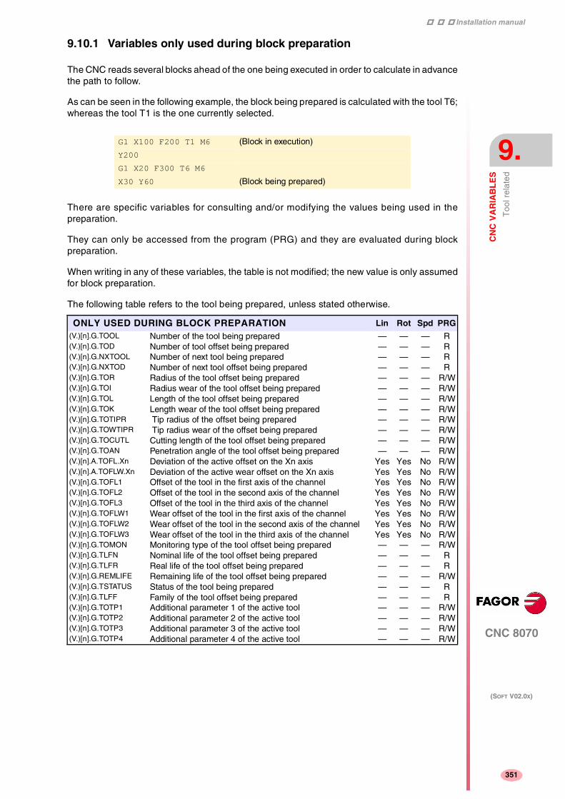
Installation manual
CNC 8070
CN
C V
AR
IAB
LE
S
Too
l rel
ated
9.
(SOFT V02.0X)
351
9.10.1 Variables only used during block preparation
The CNC reads several blocks ahead of the one being executed in order to calculate in advancethe path to follow.
As can be seen in the following example, the block being prepared is calculated with the tool T6;whereas the tool T1 is the one currently selected.
There are specific variables for consulting and/or modifying the values being used in thepreparation.
They can only be accessed from the program (PRG) and they are evaluated during blockpreparation.
When writing in any of these variables, the table is not modified; the new value is only assumedfor block preparation.
The following table refers to the tool being prepared, unless stated otherwise.
G1 X100 F200 T1 M6 (Block in execution)
Y200
G1 X20 F300 T6 M6
X30 Y60 (Block being prepared)
ONLY USED DURING BLOCK PREPARATION Lin Rot Spd PRG(V.)[n].G.TOOL Number of the tool being prepared — — — R(V.)[n].G.TOD Number of tool offset being prepared — — — R(V.)[n].G.NXTOOL Number of next tool being prepared — — — R(V.)[n].G.NXTOD Number of next tool offset being prepared — — — R(V.)[n].G.TOR Radius of the tool offset being prepared — — — R/W(V.)[n].G.TOI Radius wear of the tool offset being prepared — — — R/W(V.)[n].G.TOL Length of the tool offset being prepared — — — R/W(V.)[n].G.TOK Length wear of the tool offset being prepared — — — R/W(V.)[n].G.TOTIPR Tip radius of the offset being prepared — — — R/W(V.)[n].G.TOWTIPR Tip radius wear of the offset being prepared — — — R/W(V.)[n].G.TOCUTL Cutting length of the tool offset being prepared — — — R/W(V.)[n].G.TOAN Penetration angle of the tool offset being prepared — — — R/W(V.)[n].A.TOFL.Xn Deviation of the active offset on the Xn axis Yes Yes No R/W(V.)[n].A.TOFLW.Xn Deviation of the active wear offset on the Xn axis Yes Yes No R/W(V.)[n].G.TOFL1 Offset of the tool in the first axis of the channel Yes Yes No R/W(V.)[n].G.TOFL2 Offset of the tool in the second axis of the channel Yes Yes No R/W(V.)[n].G.TOFL3 Offset of the tool in the third axis of the channel Yes Yes No R/W(V.)[n].G.TOFLW1 Wear offset of the tool in the first axis of the channel Yes Yes No R/W(V.)[n].G.TOFLW2 Wear offset of the tool in the second axis of the channel Yes Yes No R/W(V.)[n].G.TOFLW3 Wear offset of the tool in the third axis of the channel Yes Yes No R/W(V.)[n].G.TOMON Monitoring type of the tool offset being prepared — — — R/W(V.)[n].G.TLFN Nominal life of the tool offset being prepared — — — R(V.)[n].G.TLFR Real life of the tool offset being prepared — — — R(V.)[n].G.REMLIFE Remaining life of the tool offset being prepared — — — R/W(V.)[n].G.TSTATUS Status of the tool being prepared — — — R(V.)[n].G.TLFF Family of the tool offset being prepared — — — R(V.)[n].G.TOTP1 Additional parameter 1 of the active tool — — — R/W(V.)[n].G.TOTP2 Additional parameter 2 of the active tool — — — R/W(V.)[n].G.TOTP3 Additional parameter 3 of the active tool — — — R/W(V.)[n].G.TOTP4 Additional parameter 4 of the active tool — — — R/W

Installation manual
370
CNC 8070
9.
CN
C V
AR
IAB
LE
S
PLC
rel
ated
(SOFT V02.0X)
352
9.11 PLC related
These variables are evaluated when being executed.
They have generic names.
• Replace the letter "i" with a number keeping the brackets.
This variable may be used to consult only the symbols defined with the PDEF command in the PLCprogram.
(V.)PLC.I[n] V.PLC.I[16]
(V.)PLC.signal V.PLC.auxend
STATUS PRG PLC INT R W(V.)PLC.STATUS PLC status
"0" = Stopped "1" = RunningR — R — —
RESOURCES PRG PLC INT R W(V.)PLC.I[i] Status of PLC input [i] R/W — R/W — —(V.)PLC.O[i] Status of PLC output [i] R/W — R/W — —(V.)PLC.M[i] Status of PLC mark [i] R/W — R/W — —(V.)PLC.R[i] Status of PLC register [i] R/W — R/W — —(V.)PLC.T[i] Status of PLC timer [i] R — R/W — —(V.)PLC.C[i] Status of PLC counter [i] R — R/W — —(V.)PLC.signal Status of exchange signals with CNC
(any mark or register)R/W — R/W — —
SYMBOLS PRG PLC INT R W(V.)PLC.symbol Status of the external symbols defined at the PLC R/W — R/W — —
MESSAGES PRG PLC INT R W(V.)PLC.MSG[i] Status of PLC message [n]
"0" = Inactive "1" = ActiveR/W — R/W — —
(V.)PLC.PRIORMSG Active message with the highest priority (the one with the lowest number among the active ones)
R — R — —
(V.)PLC.EMERGMSG Active emerging message (the one shown at full screen)
R — R — —
ERRORS PRG PLC INT R W(V.)PLC.ERR[i] Status of PLC error [n]
"0" = Inactive "1" = ActiveR/W — R/W — —
(V.)PLC.PRIORERR Active error with the highest priority (the one with the lowest number among the active ones)
R — R — —
TIMER PRG PLC INT R W(V.)PLC.TIMER Value of the timer enabled by PLC R/W R/W R/W Syn Syn
The PLC "TIMER" is enabled or disabled with the PLC mark TIMERON. It counts when TIMERON=1
Using the variable (V.)PLC.TIMER, it is possible to consult and/or modify its count. Value in seconds.

Installation manual
CNC 8070
CN
C V
AR
IAB
LE
S
Jog
mod
e re
late
d
9.
(SOFT V02.0X)
353
9.12 Jog mode related
With the jog selector switch on the operator panel, it is possible to select the "Type of movement",the "Resolution of the handwheel" and the "Incremental jog position".
Those values may also be forced from the PLC. When setting a value from the PLC, the CNCignores the selector switch.
These variables are synchronous read/write (R/W). All these variables are evaluated when beingexecuted.
Example to set the "10" position to the X axis handwheel:
Set variable (V.)A.PLCMMODE.X to "1"
Set variable (V.)PLC.MPGDIX to "2"
For the X axis handwheel to "obey" (not to ignore) the switch:
Set variable (V.)A.PLCMMODE.X to "0"
TYPE OF MOVEMENTLinRot
Spd PRG PLC INT
(V.)G.MANMODE Active for all the axes — — R R R(V.)G.CNCMANMODE At the switch for all of the axes — — R R R/W(V.)PLC.MANMODE By PLC for all the axes — — R R/W R
(V.)[n].A.MANMODE.Xn Active for the Xn axis Yes No R R R(V.)[n].A.CNCMMODE.Xn At the switch for the Xn axis Yes No R R R/W(V.)[n].A.PLCMMODE.Xn By PLC for the Xn axis Yes No R R/W R
These variables may have the following values:
"0" = No type is forced from the PLC.
"1" = Handwheel mode.
"2" = Continuous jog mode.
"3" = Incremental jog mode.
The variable "(V.)[n].A.MANMODE.Xn" may also have the following value:
"4" = Handwheel mode without selected axis. The handwheel mode has been selected but the axisto be moved has not been selected.
HANDWHEEL MODE RESOLUTION (POSITION) PRG PLC INT(V.)G.MPGIDX Active position for all the handwheels R R R(V.)G.CNCMPGIDX Position selected at the switch R R R/W(V.)PLC.MPGIDX Position selected by PLC R R/W R
These variables may have the following values:
"1" = Position 1
"2" = Position 10
"3" = Position 100
INCREMENTAL JOG POSITION PRG PLC INT(V.)G.INCJOGIDX Active position for all the axes R R R(V.)G.CNCINCJOGIDX Position selected by the switch R R R/W(V.)PLC.INCJOGIDX Position selected by PLC R R/W R
These variables may have the following values:
"1" = Position 1
"2" = Position 10
"3" = Position 100
"4" = Position 1000
"5" = Position 10000

Installation manual
370
CNC 8070
9.
CN
C V
AR
IAB
LE
S
Jog
mod
e re
late
d
(SOFT V02.0X)
354
The variables associated with the jog mode are modified when changing the value of the –F– fieldfrom the jog mode screen. These variables are not affected when changing the feedrate from the MDImode.
JOG FEEDRATES PRG PLC INT(V.)[n].G.FMAN JOG feedrate in G94 R/W R R/W(V.)[n].G.MANFPR JOG feedrate in G95 R/W R R/W

Installation manual
CNC 8070
CN
C V
AR
IAB
LE
S
Coo
rdin
ate
rela
ted
9.
(SOFT V02.0X)
355
9.13 Coordinate related
Remember that a spindle working in closed loop (M19 or G63) behaves like an axis.
These variables are for synchronous reading (R).
They have generic names.
• Replace the "n" character with the channel number, maintaining the brackets. The firstchannel is identified with the number 1, "0" is not a valid number.
• Replace the "Xn" character by the name, logic number or index in the channel of the axis.
• Replace the "Sn" character by the name, logic number or index in the channel of the spindle.
There are real and theoretical coordinates corresponding to the tool base and tool tip. All of themmay be referred to Machine Zero or to the current Part Zero.
A theoretical coordinate is the position that the axis must occupy at all times, a real coordinateis the one it actually occupies and the difference between these two is called "following error".
The PPOSS variable returns the target coordinate, in part coordinates and referred to the tool tip, inthe current reference system; i.e. taking into consideration the coordinate rotation, scaling factor,active incline plane, etc.
The values of the PPOS variables read from a program or from the PLC and the interface will bedifferent when the coordinate is affected by tool compensation or when machining in round cornermode. The value read by program will be the programmed coordinate whereas the value read fromthe PLC or interface will be the real (actual) coordinate considering tool radius compensation andcorner rounding.
(V.)[n].A.PPOS.Xn V.[1].A.PPOS.X V.[1].A.PPOS.1
(V.)[n].A.POS.Sn V.[2].A.POS.S V.[2].A.POS.2
RELATED TO LINEAR AND ROTARY AXES PRG PLC INT Exec(V.)[n].A.PPOS.Xn Programmed coordinates (of the tool tip) R R R No(V.)[n].G.PLPPOS1 Programmed coordinate (of the tool tip) First axis of the
channelR R R No
(V.)[n].G.PLPPOS2 Programmed coordinate (of the tool tip) Second axis of the channel
R R R No
(V.)[n].G.PLPPOS3 Programmed coordinate (of the tool tip) Third axis of the channel
R R R No
(V.)[n].A.FLWE.Xn Following error of the axis R R R Yes(V.)[n].A.APOS.Xn Part coordinates. Real of the tool base R R R Yes(V.)[n].A.ATPOS.Xn Part coordinates. Theoretical of the tool base R R R Yes(V.)[n].A.ATIPPOS.Xn Part coordinates. Real of the tool tip R R R Yes(V.)[n].A.ATIPTPOS.Xn Part coordinates. Theoretical of the tool tip R R R Yes(V.)[n].A.POS.Xn Machine coordinates. Real of the tool base R R R Yes(V.)[n].A.TPOS.Xn Machine coordinates. Theoretical of the tool base R R R Yes(V.)[n].A.TIPPOS.Xn Machine coordinates. Real of the tool tip R R R Yes(V.)[n].A.TIPTPOS.Xn Machine coordinates. Theoretical of the tool tip R R R Yes
G1 X10 V.A.PPOS.X=10
#SCALE [2]
G1 X10
(Scaling factor of ·2·)V.A.PPOS.X=20
G73 Q90
X10
[Coordinate system rotation (pattern rotation)]
V.A.PPOS.Y=20 (since the Y axis is the one that moves)

Installation manual
370
CNC 8070
9.
CN
C V
AR
IAB
LE
S
Coo
rdin
ate
rela
ted
(SOFT V02.0X)
356
SPINDLE RELATED PRG PLC INT Exec(V.)[n].A.POS.Sn Real spindle position R R R No(V.)[n].A.TPOS.Sn Theoretical spindle position R R R Yes(V.)[n].A.PPOS.Sn Programmed spindle position R R R Yes(V.)[n].A.FLWE.Sn Spindle following error R R R Yes

Installation manual
CNC 8070
CN
C V
AR
IAB
LE
S
Fee
drat
e re
late
d
9.
(SOFT V02.0X)
357
9.14 Feedrate related
These variables are synchronous read/write (R/W).
They have generic names.
• Replace the "n" character with the channel number, maintaining the brackets. The firstchannel is identified with the number 1, "0" is not a valid number.
The (V.)G.FREAL variable takes into account the accelerations and decelerations of themachine. When the axes are stopped, it returns a value of "0" and when moving it returns thevalue corresponding to the feedrate type G94/G95. On laser cutting machines, it isrecommended to use this variable so the laser power is proportional to the feedrate.
The feedrate in G94 (mm/min) or G95 (mm/rev) may be set by program or by PLC; the one setby PLC has the highest priority. When selecting a new feedrate in MDI mode, the CNC updatesthe following variables:
• (V.)G.FEED and (V.)G.PRGF with G94 active.
• (V.)G.FPREV and (V.)G.PRGFPR with G95 active.
(V.)[n].A.FRO.Xn Valid for rotary and linear axes. Also for the independent axes.
The Feedrate override % may be set by program, by PLC or with the selector switch; the one set byprogram has the highest priority and the one selected with the switch the lowest.
FEEDRATES PRG PLC INT Exec(V.)[n].G.FREAL Real CNC feedrate R R R Yes
(V.)[n].G.FEED Active feedrate in G94 R R R Yes(V.)[n].PLC.F Feedrate by PLC in G94 R R/W R Yes(V.)[n].G.PRGF Feedrate by program in G94 R R R No
(V.)[n].G.FPREV Active feedrate in G95 R R R Yes(V.)[n].PLC.FPR Feedrate by PLC in G95 R R/W R Yes(V.)[n].G.PRGFPR Feedrate by program in G95 R R R No
MACHINING TIME PRG PLC INT Exec(V.)G.FTIME Machining time in G93 R R R No
The machining time is given in seconds.
FEED-RATE OVERRIDE PRG PLC INT Exec(V.)[n].G.FRO % F active at the CNC R R R Yes(V.)[n].A.FRO.Xn % F active by axis R/W R/W R/W Yes(V.)[n].G.PRGFRO % F by program R/W R R No(V.)[n].PLC.FRO % F by PLC R R/W R Yes(V.)[n].G.CNCFRO % F at the selector switch R R R/W Yes

Installation manual
370
CNC 8070
9.
CN
C V
AR
IAB
LE
S
Rel
ated
to th
e sp
indl
e sp
eed
(SOFT V02.0X)
358
9.15 Related to the spindle speed
These variables are synchronous read/write (R/W).
They have generic names.
• Replace the "n" character with the channel number, maintaining the brackets. The firstchannel is identified with the number 1, "0" is not a valid number.
• Replace the "Sn" character by the name, logic number or index in the channel of the spindle.
These variables only limit the spindle turning speed (rpm) when constant surface speed is active. Themaximum Constant Surface Speed may be set by program or by PLC; the one set by PLC has thehighest priority.
V.A.SREAL.Sn V.A.SREAL.S
TURNING SPEED PRG PLC INT Exec(V.)[n].A.SREAL.Sn Real spindle speed R R R Yes
It takes the spindle speed override into account.
When the spindle is stopped, it returns a value of 0. When working in G96 and G97, the speed is in rpmand when working with M19, in º/min.
SPINDLE SPEED IN G97 PRG PLC INT Exec(V.)[n].A.SPEED.Sn S active in rpm (G97) R R R Yes(V.)[n].PLC.S.Sn S by PLC in rpm R R/W R Yes(V.)[n].A.PRGS.Sn S by program in rpm R R R No
The speed may be set by program or by PLC; the one set by PLC has the highest priority.
SPINDLE SPEED IN CSS PRG PLC INT Exec(V.)[n].A.CSS.Sn Active CSS R R R Yes(V.)[n].PLC.CSS.Sn CSS by PLC R R/W R Yes(V.)[n].A.PRGCSS.Sn CSS by program R R R No
The speed may be set by program or by PLC; the one set by PLC has the highest priority.
MAXIMUM CONSTANT SURFACE SPEED PRG PLC INT Exec(V.)[n].A.SLIMIT.Sn S limit active in Constant Surface Speed mode R R R Yes(V.)[n].PLC.SL.Sn S limit via PLC in Constant Surface Speed mode R R/W R Yes(V.)[n].A.PRGSL.Sn S limit via program in Constant Surface Speed mode R R R No
SPINDLE SPEED OVERRIDE PRG PLC INT Exec(V.)[n].A.SSO.Sn % S active at the CNC R R R Yes(V.)[n].A.PRGSSO.Sn % S by program R/W R R No(V.)[n].PLC.SSO.Sn % S by PLC R R/W R Yes(V.)[n].A.CNCSSO.Sn % S at the switch R R R/W Yes
The spindle speed override may be set by program, by PLC or with the selector switch; the one set byprogram has the highest priority and the one set with the selector switch has the lowest.
SPEED IN M19 PRG PLC INT Exec(V.)[n].A.SPOS.Sn Active speed in M19 R R R Yes(V.)[n].PLC.SPOS.Sn Speed in M19 set by PLC R R/W R Yes(V.)[n].A.PRGSPOS.Sn Speed in M19 by program R R R No

Installation manual
CNC 8070
CN
C V
AR
IAB
LE
S
Rel
ated
to th
e pr
ogra
mm
ed fu
nctio
ns
9.
(SOFT V02.0X)
359
9.16 Related to the programmed functions
They have generic names.
• Replace the "n" character with the channel number, maintaining the brackets. The firstchannel is identified with the number 1, "0" is not a valid number.
• Replace the "Xn" character by the name, logic number or index in the channel of the axis.
• Replace the letters "i" and "x" with a number keeping the brackets.
These variables are for synchronous reading (R).
Variables GS and MS returned a coded value. Each function has a bit that indicates whether therelevant function is active (=1) or not (=0). Examples for status consultation:
(V.)G.GS[1] indicates whether G1 is active (=1) or not (=0)
(V.)G.MS[6] indicates whether M6 is active (=1) or not (=0)
The HGS1..10 variable returns the 32-bit coded status; 1 bit per function. The HGS1 variablecorresponds to functions G0 through G31, HGS2 corresponds to G32 through G63 and so on.
The variables HGS and HMS return a coded value. Each function has a bit that indicates whether therelevant variable will be displayed (=1) or not (=0). Bit 0, the least significant bit, corresponds to theG0 or M0 function, bit 1 to G1 or M1 and so on.
These variables are read/write (R/W) and are evaluated during block preparation.
The "(V.)P.name" variables maintain their value in local and global subroutines called upon from theprogram.
The "(V.)S.name" variables maintain their value between programs and after a reset. To initialize thesevariables, use the instruction #DELETE.
"G" AND "M" FUNCTIONS PRG PLC INT Exec(V.)[n].G.GS[i] Status of the requested "G" function R R R No(V.)[n].G.MS[i] Status of the requested "M" function R R R No(V.)[n].G.HGS1..10 Status of the requested "G" (32 bit) functions R R R No(V.)[n].G.HGS History of "G" functions to be displayed — — R Yes(V.)[n].G.HMS History of "M" functions of the master spindle to be
displayed— — R Yes
(V.)[n].G.HMSi History of "M" functions of the "i" spindle to be displayed — — R Yes
PARAMETERS AND VARIABLES PRG PLC INT(V.)P.name Local user variables of the program R/W — —(V.)S.name Global user variables of the program R/W — —(V.)C.(A-Z) Value of the canned cycle calling parameter R/W — —(V.)C.CALLP_(A-Z) Parameter programmed in the call to a canned cycle
"0" = It has not been programmed "1" = It has been programmedR — —
(V.)C.P_(A-Z) Value of the positioning cycle calling parameter R/W — —(V.)C.P_CALLP_(A-Z) Parameter programmed in the call to a positioning cycle
"0" = It has not been programmed "1" = It has been programmedR — —
(V.)C.PCALLP_(A-Z) Parameter programmed in a call to a subroutine G18x, #PCALL or #MCALL
"0" = It has not been programmed "1" = It has been programmed
R — —
G90 G81 Z0 I-15
V.C.CALLP_Z = 1
V.C.CALLP_I = 1
V.C.CALLP_K = 0
V.C.Z = 0
V.C.Z = -15
G160 A30 X100 K10 P6
V.C.P_CALLP_A = 1
V.C.P_CALLP_K = 1
V.C.P_CALLP_R = 0
V.C.P_A = 30
V.C.P_X = 100
#PCALL sub.nc A12.56 D3
V.C.PCALLP_A = 1
V.C.PCALLP_D = 1

Installation manual
370
CNC 8070
9.
CN
C V
AR
IAB
LE
S
Rel
ated
to th
e pr
ogra
mm
ed fu
nctio
ns
(SOFT V02.0X)
360
These variables are read-only (R) Synchronous and are evaluated during block preparation.
Here are some examples where the starting point is X0 Y0.
Being function G265 active, the CNC recalculates the center if the arc is not exact but it is withintolerance.
Being function G264 active, if the arc is not exact, but it is within tolerances, it executes an arc withthe radius calculated from the starting point. It keeps its center.
These variables are read-only (R) Synchronous and are evaluated during block preparation.
(V.)[n].G.MIRROR The least significant bits are used, one per axis (1= active and 0=not active).The least significant bit is for the first axis, the next one for the second axis and so on.
ARC RELATED PRG PLC INT(V.)[n].G.R Arc radius R R R(V.)[n].G.I/J/K Arc center coordinates (I, J, K) R R R(V.)[n].G.CIRERR[i] Arc center correction R R R
G2 X120 Y120.001 I100 J20
V.G.R = 101.980881
V.G.I = 100.0004
V.G.J = 20.0004
V.G.CIRERR[1] = -0.000417
V.G.CIRERR[2] = -0.000417
G2 X120 Y120.001 I100 J20
V.G.R = 101.981371
V.G.I = 100
V.G.J = 20
V.G.CIRERR[1] = 0
V.G.CIRERR[2] = 0
MIRROR IMAGE PRG PLC INT(V.)[n].G.MIRROR Active mirror images R R R(V.)[n].G.MIRROR1 Mirror image active on the first axis of the channel R R R(V.)[n].G.MIRROR2 Mirror image active on the second axis of the channel R R R(V.)[n].G.MIRROR3 Mirror image active on the third axis of the channel R R R
SCALING FACTOR PRG PLC INT(V.)[n].G.SCALE It indicates the active general scaling factor R R R
POLAR ORIGIN PRG PLC INT(V.)[n].G.PORGF Position of the polar origin referred to part zero (abscissa) R R R(V.)[n].G.PORGS Position of the polar origin referred to part zero (ordinate) R R R
COORDINATE SYSTEM ROTATION (PATTERN ROTATION) PRG PLC INT(V.)[n].G.ROTPF Position of the rotation center referred to part zero (abscissa) R R R(V.)[n].G.ROTPS Position of the rotation center referred to part zero (ordinate) R R R(V.)[n].G.ORGROT Rotation angle of the coordinate system R R R
AXIS SLAVING PRG PLC INT(V.)[n].G.LINKACTIVE Slaving status R R R

Installation manual
CNC 8070
CN
C V
AR
IAB
LE
S
Rel
ated
to th
e pr
ogra
mm
ed fu
nctio
ns
9.
(SOFT V02.0X)
361
(V.)[n].G.PENDRPT and (V.)[n].G.PENDNR indicate the number of repetitions pending to execute. Inthe first execution, its value is the programmed number of repetitions minus one and in the last one,its value is zero.
These variables are read-only (R) synchronous and are evaluated during execution. Theycorrespond to linear and rotary axes.
Here is an example where the starting point is X0 and G100 X100 F100 has programmed . The valueof (V.)A.MEASIN.Xn is updated (refreshed) when probing with G101.
These variables are read-only (R) synchronous and are evaluated during block preparation.
These variables are read-only (R) synchronous and are evaluated during execution. Thesevariables correspond to linear and rotary axes; not to spindles.
These values are maintained during the execution of the program even when canceling manualintervention.
BLOCK REPETITION PRG PLC INT(V.)[n].G.PENDRPT Number of pending repetitions with #RPT R R R(V.)[n].G.PENDNR Number of pending repetitions with NR R R R
PROBING (G100, G101, G102) PRG PLC INT(V.)[n].A.MEAS.Xn Measured value. Tool base coordinates R R R(V.)[n].A.ATIPMEAS.Xn Measured value. Tool tip coordinates R — —(V.)[n].G.PLMEAS1 Value measured on the first axis of the channel. Tool tip
coordinatesR — —
(V.)[n].G.PLMEAS2 Value measured on the second axis of the channel. Tool tip coordinates
R — —
(V.)[n].G.PLMEAS3 Value measured on the third axis of the channel. Tool tip coordinates
R — —
(V.)[n].A.MEASOF.Xn Difference with respect to programmed point R R R(V.)[n].A.MEASOK.Xn Probing finished
"0" = No "1"= YesR R R
(V.)[n].A.MEASIN.Xn Coordinate that includes measurement offset R R R(V.)[n].G.PLMEASOKx Probing on the plane axes completed R — —
V.A.MEAS.X = 95
V.A.MEASOF.X = -5
V.A.MEASOK.X = 1
PROBE PRG PLC INT(V.)[n].G.ACTIVPROBE Number of the active probe R R R
MOVEMENTS IN MANUAL INTERVENTION PRG PLC INT(V.)[n].A.MANOF.Xn Distance moved with G200 or inspection R R R(V.)[n].A.ADDMANOF.Xn Distance moved with G201 R R R

Installation manual
370
CNC 8070
9.
CN
C V
AR
IAB
LE
S
Rel
ated
to th
e pr
ogra
mm
ed fu
nctio
ns
(SOFT V02.0X)
362
These variables are read/write (R/W) synchronous and are evaluated during block preparation.These variables correspond to linear and rotary axes.
They indicate the position occupied by the rotary axes of the spindle head and the one (target) theymust occupy in order to position the tool perpendicular to the defined plane. They are very useful whenthe spindle is not fully motorized (mono-rotary or manual spindles).
On angular (swivel) spindle heads, there are two possible solutions when calculating this targetposition:
(V.)G.TOOLORIF1 and (V.)G.TOOLORIS1 indicate the shortest way for the main rotary axis withrespect to the zero position.
(V.)G.TOOLORIF2 and (V.)G.TOOLORIS2 indicate the longest way for the main rotary axis withrespect to the zero position.
These variables are read-only (R) Synchronous and are evaluated during block preparation.These variables correspond to linear and rotary axes.
These variables are read-only (R) synchronous and are evaluated execution time.
These variables correspond to the transformation matrix from theoretical reference system to the realreference system.
These variables are read-only (R) synchronous and are evaluated during execution.
KINEMATICS (POSITION) PRG PLC INT(V.)[n].G.POSROTF Current position of the main rotary axis R/W R/W R/W(V.)[n].G.POSROTS Current position of the secondary rotary axis R/W R/W R/W(V.)[n].G.TOOLORIF1 Target position for the main rotary axis R R R(V.)[n].G.TOOLORIS1 Target position for the secondary rotary axis R R R(V.)[n].G.TOOLORIF2 Target position for the main rotary axis R R R(V.)[n].G.TOOLORIS2 Target position for the secondary rotary axis R R R
INCLINE PLANES PRG PLC INT(V.)[n].G.CS Number of the active CS function R R R(V.)[n].G.ACS Number of the active ACS function R R R(V.)[n].G.TOOLCOMP Compensation function active
"1" = RTCP "2" = TLC "3" = NoneR R R
DIE RESULTING FROM THE INCLINE PLANE PRG PLC INT(V.)[n].G.CSMAT1 Die resulting from the incline plane. Element row 1 column 1 R R R(V.)[n].G.CSMAT2 Die resulting from the incline plane. Element row 1 column 2 R R R(V.)[n].G.CSMAT3 Die resulting from the incline plane. Element row 1 column 3 R R R(V.)[n].G.CSMAT4 Die resulting from the incline plane. Element row 2 column 1 R R R(V.)[n].G.CSMAT5 Die resulting from the incline plane. Element row 2 column 2 R R R(V.)[n].G.CSMAT6 Die resulting from the incline plane. Element row 2 column 3 R R R(V.)[n].G.CSMAT7 Die resulting from the incline plane. Element row 3 column 1 R R R(V.)[n].G.CSMAT8 Die resulting from the incline plane. Element row 3 column 2 R R R(V.)[n].G.CSMAT9 Die resulting from the incline plane. Element row 3 column 3 R R R(V.)[n].G.CSMAT10 Offset of the current coordinate system referred to machine zero
on the first axisR R R
(V.)[n].G.CSMAT11 Offset of the current coordinate system referred to machine zero on the second axis
R R R
(V.)[n].G.CSMAT12 Offset of the current coordinate system referred to machine zero on the third axis
R R R
SYNCHRONIZATION OF CHANNELS PRG PLC INT(V.)[n].G.MEETST[i] Status of the MEET type [i] mark in the [n] channel R R R(V.)[n].G.WAITST[i] Status of the WAIT type [i] mark in the [n] channel R R R(V.)[n].G.MEETCH[i] MEET type mark expected by the [n] channel of the [i] channel R R R(V.)[n].G.WAITCH[i] WAIT type mark expected by the [n] channel from the [i] channel R R R

Installation manual
CNC 8070
CN
C V
AR
IAB
LE
S
Rel
ated
to th
e pr
ogra
mm
ed fu
nctio
ns
9.
(SOFT V02.0X)
363
These variables are read-only (R) synchronous and are evaluated during execution. Thesevariables correspond to linear and rotary axes and spindles.
The PLC reading of ACFGAIN comes in tenths (x10) The PLC reading of FFGAIN comes inhundredths (x100) Ver "Access to numeric values from the PLC" en la página 326.
FEED-FORWARD AND AC-FORWARD PRG PLC INT(V.)[n].A.FFGAIN.Xn Active percentage of feed-forward R R R(V.)[n].A.ACFGAIN.Xn Active percentage of AC-forward R R R

Installation manual
370
CNC 8070
9.
CN
C V
AR
IAB
LE
S
Rel
ated
to th
e in
depe
nden
t axe
s
(SOFT V02.0X)
364
9.17 Related to the independent axes
They have generic names.
• Replace the "n" character with the channel number, maintaining the brackets. The firstchannel is identified with the number 1, "0" is not a valid number.
• Replace the "Xn" character by the name, logic number or index in the channel of the axis.
These variables are read/write (R/W) synchronous and are evaluated during execution.
These variables are read/write (R/W) synchronous and are evaluated during execution. Thesevariables correspond to linear and rotary axes.
These variables are read/write (R/W) synchronous and are evaluated during execution. Thesevariables correspond to linear and rotary axes and spindles.
The PLC reading of GEARADJ comes in hundredths (x100) Ver "Access to numeric values fromthe PLC" en la página 326.
INDEPENDENT AXES PRG PLC INT(V.)[n].G.IBUSY An independent axis is in execution R R R
INDEPENDENT AXES (POSITIONING) PRG PLC INT(V.)[n].A.IORG.Xn Offset for the independent axis R/W R/W R/W(V.)[n].A.IPRGF.Xn Feedrate programmed in the independent axis R R R(V.)[n].A.IPPOS.Xn Coordinate programmed for the independent axis R R R(V.)[n].A.ITPOS.Xn Theoretical coordinate of the independent axis R R R
INDEPENDENT AXES (SYNCHRONIZATION) PRG PLC INT(V.)[n].A.SYNCTOUT.Xn Maximum time to establish synchronism R/W R/W R/W(V.)[n].A.SYNCVEL.Xn Synchronization speed R/W R/W R/W(V.)[n].A.SYNCPOSW.Xn Maximum position difference to start correcting it R/W R/W R/W(V.)[n].A.SYNCVELW.Xn Maximum velocity difference to start correcting it R/W R/W R/W(V.)[n].A.SYNCPOSOFF.Xn Position offset for synchronization R/W R/W R/W(V.)[n].A.SYNCVELOFF.Xn Velocity offset for synchronization R/W R/W R/W(V.)[n].A.GEARADJ.Xn Fine adjustment of the gear ratio for the synchronization
movementR R R

Installation manual
CNC 8070
CN
C V
AR
IAB
LE
S
Rel
ated
to th
e m
achi
ne c
onfig
urat
ion
9.
(SOFT V02.0X)
365
9.18 Related to the machine configuration
They have generic names.
• Replace the "n" character with the channel number, maintaining the brackets. The firstchannel is identified with the number 1, "0" is not a valid number.
• Replace the "Xn" character by the name, logic number or index in the channel of the axis orof the spindle.
• Replace the letters "i" and "x" with a number keeping the brackets.
These variables are read-only (R) synchronous and are evaluated during execution.
When parking an axis, it is a good idea to know which axes are available. Variables(V.)[n].G.AXISNAME and (V.).G.GAXISNAME indicate which axes are available. If an axis is notavailable, this variable returns the "?".
These variables are synchronous read/write (R/W). The variables correspond to linear and rotaryaxes.
There are 2 software limits. The CNC applies the most restrictive one.
Variables POSLIMIT and NEGLIMIT correspond to the limits set by machine parameters. Whenmodifying these variables, the CNC assumes those values as the new limits from then on.
They keep their value after a Reset, but are reset when validating the machine parameters and whenturning the CNC on. Variables POSLIMIT and NEGLIMINT assume the values of the machineparameters and RTPOSLIMIT and RTNEGLIMIT assume the maximum values.
These variables are read-only (R) synchronous and are evaluated during execution. Thesevariables correspond to linear and rotary axes.
It returns the resulting measurement of the active kinematics on that axis. It may be a particular valueof DATA (kinematics table) or the combination of several of them depending on the type of kinematics.
MACHINE CONFIGURATION PRG PLC INT(V.)G.NUMCH Number of channels R R R(V.)[n].G.AXISCH Name the axes of the channel — — R(V.)[n].A.ACTCH.Xn Current channel of the axis or of the spindle R R R(V.)[n].A.ACTIVSET.Xn Active axis or spindle set R R R(V.)[n].G.AXIS Number of axes of the channel R R R(V.)[n].G.NAXIS Number of axes of the channel including the empty positions of
the yielded axesR R R
(V.)[n].G.AXISNAMEx Name of the "x" axis of the channel R R R(V.)G.GAXISNAMEx Name of the "x" axis of the system R R R(V.)[n].G.NSPDL Number of spindles of the channel R R R(V.)[n].G.SPDLNAMEx Name of the "x" spindle of the channel R R R(V.)G.GSPDLNAMEx Name of the "x" spindle of the system R R R(V.)[n].G.MASTERSP Master spindle of the channel R R R
LINEAR AND ROTARY AXIS TRAVEL LIMITS PRG PLC INT Exec(V.)[n].A.POSLIMIT.Xn Positive software limit R/W R R No(V.)[n].A.NEGLIMIT.Xn Negative software limit R/W R R No(V.)[n].A.RTPOSLIMIT.Xn Second positive software travel limit R/W R/W R/W Yes(V.)[n].A.RTNEGLIMIT.Xn Second negative software travel limit R/W R/W R/W Yes(V.)[n].G.SOFTLIMIT Software limits reached R R R Yes
KINEMATICS (DIMENSIONS) PRG PLC INT(V.)[n].A.HEADOF.Xn Dimension of the kinematics R R R
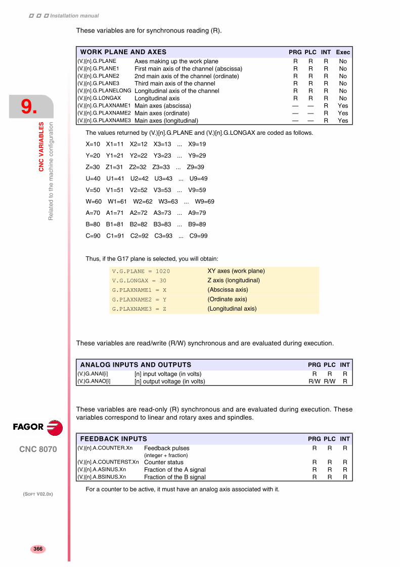
Installation manual
370
CNC 8070
9.
CN
C V
AR
IAB
LE
S
Rel
ated
to th
e m
achi
ne c
onfig
urat
ion
(SOFT V02.0X)
366
These variables are for synchronous reading (R).
The values returned by (V.)[n].G.PLANE and (V.)[n].G.LONGAX are coded as follows.
X=10 X1=11 X2=12 X3=13 ... X9=19
Y=20 Y1=21 Y2=22 Y3=23 ... Y9=29
Z=30 Z1=31 Z2=32 Z3=33 ... Z9=39
U=40 U1=41 U2=42 U3=43 ... U9=49
V=50 V1=51 V2=52 V3=53 ... V9=59
W=60 W1=61 W2=62 W3=63 ... W9=69
A=70 A1=71 A2=72 A3=73 ... A9=79
B=80 B1=81 B2=82 B3=83 ... B9=89
C=90 C1=91 C2=92 C3=93 ... C9=99
Thus, if the G17 plane is selected, you will obtain:
These variables are read/write (R/W) synchronous and are evaluated during execution.
These variables are read-only (R) synchronous and are evaluated during execution. Thesevariables correspond to linear and rotary axes and spindles.
For a counter to be active, it must have an analog axis associated with it.
WORK PLANE AND AXES PRG PLC INT Exec(V.)[n].G.PLANE Axes making up the work plane R R R No(V.)[n].G.PLANE1 First main axis of the channel (abscissa) R R R No(V.)[n].G.PLANE2 2nd main axis of the channel (ordinate) R R R No(V.)[n].G.PLANE3 Third main axis of the channel R R R No(V.)[n].G.PLANELONG Longitudinal axis of the channel R R R No(V.)[n].G.LONGAX Longitudinal axis R R R No(V.)[n].G.PLAXNAME1 Main axes (abscissa) — — R Yes(V.)[n].G.PLAXNAME2 Main axes (ordinate) — — R Yes(V.)[n].G.PLAXNAME3 Main axes (longitudinal) — — R Yes
V.G.PLANE = 1020 XY axes (work plane)
V.G.LONGAX = 30 Z axis (longitudinal)
G.PLAXNAME1 = X (Abscissa axis)
G.PLAXNAME2 = Y (Ordinate axis)
G.PLAXNAME3 = Z (Longitudinal axis)
ANALOG INPUTS AND OUTPUTS PRG PLC INT(V.)G.ANAI[i] [n] input voltage (in volts) R R R(V.)G.ANAO[i] [n] output voltage (in volts) R/W R/W R
FEEDBACK INPUTS PRG PLC INT(V.)[n].A.COUNTER.Xn Feedback pulses
(integer + fraction)R R R
(V.)[n].A.COUNTERST.Xn Counter status R R R(V.)[n].A.ASINUS.Xn Fraction of the A signal R R R(V.)[n].A.BSINUS.Xn Fraction of the B signal R R R

Installation manual
CNC 8070
CN
C V
AR
IAB
LE
S
Rel
ated
to th
e m
achi
ne c
onfig
urat
ion
9.
(SOFT V02.0X)
367
These variables are read/write (R/W) synchronous and are evaluated during execution. Theycorrespond to linear and rotary axes and to the spindle.
The PLC reading of TORQUE comes in tenths (x10) Ver "Access to numeric values from the PLC"en la página 326.
These variables are read/write (R/W) synchronous and are evaluated during block execution.They are valid for linear and rotary axes and for the spindle.
In order for the feed-forward and the AC-forward defined this way to be taken into account, they mustbe active by machine parameter; i.e. by means of machine parameter FFWTYPE if it is an analog driveor a simulated drive or parameter OPMODEP if it is a Sercos drive.
The values defined by these variables prevail over the ones defined by machine parameters or byprogram. Setting the variables with a negative value cancels their effect ("0" is a valid value). Thesevariables are initialized neither by a reset nor when validating the parameters.
The PLC will read them in the following units. Ver "Access to numeric values from the PLC" en lapágina 326.
The PLC reading of PLCACFGAIN comes in tenths (x10)
The PLC reading of PLCFFGAIN comes in hundredths (x100)
These variables are read-only (R) synchronous and are evaluated in the execution.
RELATED TO THE TANDEM AXIS PRG PLC INT(V.)[n].A.TPIIN.Xn Input of the PI of the master axis of the tandem (in rpm) R R R(V.)[n].A.TPIOUT.Xn Output of the PI of the master axis of the tandem (in rpm) R R R(V.)[n].A.TFILTOUT.Xn Output of the pre-load filter R R R(V.)[n].A.PRELOAD.Xn Preload R/W R/W R/W(V.)[n].A.FTEO.Xn Velocity command for Sercos R R R(V.)[n].A.TORQUE.Xn Current torque in Sercos R R R
VARIABLES TO BE SET VIA PLC PRG PLC INT(V.)[n].A.PLCFFGAIN.Xn % of feed-forward programmed from the PLC R R/W R(V.)[n].A.PLCACFGAIN.Xn % of AC-forward programmed from the PLC R R/W R(V.)[n].A.PLCPROGAIN.Xn Proportional gain programmed from the PLC R R/W R
To set the Z axis variable to ·99.1· from the PLC:
()=MOV 991 R1
()=CNCWR(R1,A.PLCACFGAIN.Z,M1000)
To set the X axis variable to ·99.12· from the PLC:
()=MOV 9912 R1
()=CNCWR(R1,A.PLCFFGAIN.X,M1000)
VARIABLES FOR ADJUSTING THE POSITION PRG PLC INT(V.)[n].A.POSINC.Xn Real position increment of the current sampling period R R R(V.)[n].A.TPOSINC.Xn Theoretical position increment of the current sampling period R R R(V.)[n].A.PREVPOSINC.Xn Real position increment of the previous sampling period R R R
FINE ADJUSTMENT VARIABLES PRG PLC INT(V.)[n].A.FEED.Xn Real instantaneous feedrate value R R R(V.)[n].A.TFEED.Xn Theoretical instantaneous feedrate value R R R(V.)[n].A.ACCEL.Xn Real instantaneous acceleration value R R R(V.)[n].A.TACCEL.Xn Theoretical instantaneous acceleration value R R R(V.)[n].A.JERK.Xn Real instantaneous jerk value R R R(V.)[n].A.TJERK.Xn Theoretical instantaneous jerk value R R R

Installation manual
370
CNC 8070
9.
CN
C V
AR
IAB
LE
S
Oth
er v
aria
bles
(SOFT V02.0X)
368
9.19 Other variables
They have generic names.
• Replace the "n" character with the channel number, maintaining the brackets. The firstchannel is identified with the number 1, "0" is not a valid number.
• Replace the "Xn" character by the name, logic number or index in the channel of the axis orof the spindle.
• Replace the letter "i" with a number keeping the brackets.
These variables are read-only (R) synchronous and are evaluated during execution.
The information of the CNC status is Binary coded as follows.
STATUS
0000 (0H) No Ready
0001 (1H) Ready
0010 (2H) In execution
0100 (4H) Interrupted
1000 (8H) In error
FULLSTATUS
The high portion contains the information of the STATUS variable and its low portion provides furthercoded information. FULLSTATUS = 0000 (STATUS) 0000 (code).
The list of codes for the low portion of FULLSTATUS is:
0000 (0H) In Reset
0001 (1H) In JOG
0010 (2H) In MDI
0011 (3H) In program
0100 (4H) Stopped by M0
0101 (5H) Stopped by STOP
0110 (6H) Stopped in Single block mode
1001 (9H) Checking syntax
1010 (AH) Block search (without moving the axes)
1011 (BH) Block search finished. In stand by
1100 (CH) Calculating execution times
1101 (DH) In simulation
Example:
In RESET, the low portion of FULLSTATUS is "0" (0000) In JOG mode its value is "1" (0001). InSIMULATION mode is 13 (1101) and so on.
FULLSTATUS=514 (202H) means in execution (0010) + MDI (0010).
SOFTWARE VERSION PRG PLC INT(V.)G.VERSION CNC version and release number R R R
CNC STATUS PRG PLC INT(V.)[n].G.STATUS CNC status (brief) R R R(V.)[n].G.FULLSTATUS CNC status (detailed) R R R(V.)G.CNCERR CNC error number R R R

Installation manual
CNC 8070
CN
C V
AR
IAB
LE
S
Oth
er v
aria
bles
9.
(SOFT V02.0X)
369
These variables are read-only (R) synchronous and are evaluated during execution.
(V.)[n].G.CYTIME is set to 0 at every new execution even of the same program. It does notmeasure the time that execution has been stopped.
These variables are read/write (R/W) synchronous and are evaluated during execution.
(V.)[n].G.PARTC Is initialized when executing a new program and every time an M30 or anM02 is executed
(V.)[n].G.FIRST Is considered first time execution (=1) every time a new program is selected.
It must be borne in mind that both variables are initialized when changing the program being executedin the channel, even with the #EXEC instruction. For example, when selecting and executing thefollowing program, both variables are initialized. When executing the #EXEC instruction, both variablesare re-initialized because the program in execution has changed. If then, this program is executedagain, the program in execution changes again and both variables are updated.
G0 X100
#EXEC [“program2.nc”, 1]
M30
In this case, to keep track of how many times the program has been executed, it is recommended touse an arithmetic parameter at the end of the program like a counter.
These variables are read/write (R/W) synchronous and are evaluated during execution.
The single block function may be activated or canceled from the keyboard (V.)G.SBLOCK or from thePLC (SBLOCK mark). To activate it, just set one of them high (=1), but to cancel it both must be low(=0).
The conditional stop, block skip and rapid functions are selected via PLC (marks M01STOP,BLKSKIP1 and MANRAPID respectively).
TIMES PRG PLC INT(V.)G.DATE Date in year-month-day format
(April 25th, 1999 => 990425)R R R
(V.)G.TIME Time in hours-minutes-seconds format(at 18h 22min 34seg => 182234
R R R
(V.)G.CLOCK Seconds since the CNC was turned on R R R(V.)[n].G.CYTIME Part-program execution time (in hundredths of a second) R R R
PARTS COUNTER PRG PLC INT(V.)[n].G.PARTC Parts counter R/W R/W R/W(V.)[n].G.FIRST First time a program is executed R R R/W
SINGLE BLOCK, RAPID FUNCTIONS, ETC. PRG PLC INT(V.)[n].G.SBOUT Single block function activated R R R(V.)[n].G.SBLOCK Single block function requested via keyboard R R R/W(V.)[n].G.BLKSKIP Block skip function ( \ ) activated R R R/W(V.)[n].G.M01STOP Conditional stop function (M01) activated R R R/W(V.)[n].G.RAPID Rapid function activated R R R/W

Installation manual
370
CNC 8070
9.
CN
C V
AR
IAB
LE
S
Oth
er v
aria
bles
(SOFT V02.0X)
370
These variables are synchronous read-only (R).
(V.)[n].G.FILEOFFSET indicates the number of characters existing between the first character of theprogram and the line being executed. It may be used to highlight the line being executed.
These variables are read/write (R/W) synchronous and are evaluated during execution.
These variables are read/write (R/W) synchronous and are evaluated during execution.
(V.)G.KEY To read the last key that has been accepted by the CNC or simulate thekeyboard from the PLC by writing in it the code of the desired key.
These variables are synchronous read/write (R/W).
These variables are read-only (R) synchronous and are evaluated during execution.
Jog movements are allowed when the jog mode or the TEACH-IN mode is active, during toolinspection and when functions G200 and G201 are active.
PROGRAM RELATED PRG PLC INT Exec(V.)[n].G.FILENAME Name of the program in execution — — R Yes(V.)[n].G.PRGPATH Path of the program in execution — — R Yes(V.)[n].G.FILEOFFSET Position occupied by the line in execution R R R Yes(V.)[n].G.BLKN Last block executed (number)
(If none, value of -1)R R R No
RELATED TO AXES AND SPINDLESLinRot
SpdPRGPLC
INT
(V.)[n].A.INPOS.Xn Axis or spindle in position Yes Yes R R(V.)[n].A.DIST.Xn Distance traveled by the axis or spindle Yes Yes R/W R/W(V.)G.ENDREP All the axes are repositioned — — R R(V.)[n].G.SPDLREP M function to be used to reposition the spindle after a tool
inspection— — R R
SIMULATION OF KEYS PRG PLC INT(V.)G.KEY Code of the last key accepted by the CNC. R R/W R
Keyboard simulation from the PLC.
;R110=0 and R111=1
··· = CNCRD(G.KEY, R100, M102)
It assigns to register R100 the code of the key pressed last.
··· = CNCWR(R101, G.KEY, M101)
It indicates to the CNC that a key has been pressed whose code is indicated inregister R101.
CHANNEL PRG PLC INT Exec(V.)[n].G.CNCHANNEL Channel number R R R No(V.)G.FOCUSCHANNEL Channel with active focus R R/W R/W Yes
JOG MOVEMENTS PRG PLC INT(V.)[n].G.INTMAN Movements in jog mode are allowed R R R

Installation manual
CNC 8070
CN
C V
AR
IAB
LE
S
Alp
habe
tical
list
ing
of v
aria
bles
9.
(SOFT V02.0X)
371
9.20 Alphabetical listing of variables
(V.)[n].A.ACCEL.Xn Real instantaneous acceleration value..................................................... Page 367(V.)[n].A.ACFGAIN.Xn Active percentage of AC-forward .............................................................. Page 363(V.)[n].A.ACTCH.Xn Current channel of the axis or of the spindle ............................................ Page 365(V.)[n].A.ACTIVSET.Xn Active axis or spindle set .......................................................................... Page 365(V.)[n].A.ADDMANOF.Xn Distance moved with G201...................................................................... Page 361(V.)[n].A.APOS.Xn Part coordinates. Real of the tool base .................................................... Page 355(V.)[n].A.ASINUS.Xn Fraction of the A signal ............................................................................. Page 366(V.)[n].A.ATIPMEAS.Xn Measured value. Tool tip coordinates ....................................................... Page 361(V.)[n].A.ATIPPOS.Xn Part coordinates. Real of the tool tip ........................................................ Page 355(V.)[n].A.ATIPTPOS.Xn Part coordinates. Theoretical of the tool tip .............................................. Page 355(V.)[n].A.ATPOS.Xn Part coordinates. Theoretical of the tool base .......................................... Page 355(V.)[n].A.BSINUS.Xn Fraction of the B signal ............................................................................. Page 366(V.)[n].A.CNCMMODE.Xn At the switch for the Xn axis ..................................................................... Page 353(V.)[n].A.CNCSSO.Sn % S at the switch ...................................................................................... Page 358(V.)[n].A.COUNTER.Xn Feedback pulses....................................................................................... Page 366(V.)[n].A.COUNTERST.Xn Counter status .......................................................................................... Page 366(V.)[n].A.CSS.Sn Active CSS................................................................................................ Page 358(V.)[n].A.DIST.Xn Distance traveled by the axis or spindle ................................................... Page 370(V.)[n].A.FEED.Xn Real instantaneous feedrate value ........................................................... Page 367(V.)[n].A.FFGAIN.Xn Active percentage of feed-forward............................................................ Page 363(V.)[n].A.FIX.Xn Offset of current fixture for Xn axis ........................................................... Page 348(V.)[n].A.FIXT[i].Xn Offset of [i] fixture for the Xn axis.............................................................. Page 348(V.)[n].A.FLWE.Sn Spindle following error .............................................................................. Page 356(V.)[n].A.FLWE.Xn Following error of the axis......................................................................... Page 355(V.)[n].A.FRO.Xn % F active by axis..................................................................................... Page 357(V.)[n].A.FTEO.Xn Velocity command for Sercos ................................................................... Page 367(V.)[n].A.GEARADJ.Xn Fine adjustment of the gear ratio for the synchronization movement ....... Page 364(V.)[n].A.HEADOF.Xn Dimension of the kinematics..................................................................... Page 365(V.)[n].A.INPOS.Xn Axis or spindle in position ......................................................................... Page 370(V.)[n].A.IORG.Xn Offset for the independent axis................................................................. Page 364(V.)[n].A.IPPOS.Xn Coordinate programmed for the independent axis ................................... Page 364(V.)[n].A.IPRGF.Xn Feedrate programmed in the independent axis ........................................ Page 364(V.)[n].A.ITPOS.Xn Theoretical coordinate of the independent axis........................................ Page 364(V.)[n].A.JERK.Xn Real instantaneous jerk value .................................................................. Page 367(V.)[n].A.MANMODE.Xn Active for the Xn axis ................................................................................ Page 353(V.)[n].A.MANOF.Xn Distance moved with G200 or inspection ................................................ Page 361(V.)[n].A.MEAS.Xn Measured value. Tool base coordinates ................................................... Page 361(V.)[n].A.MEASIN.Xn Coordinate that includes measurement offset .......................................... Page 361(V.)[n].A.MEASOF.Xn Difference with respect to programmed point ........................................... Page 361(V.)[n].A.MEASOK.Xn Probing finished........................................................................................ Page 361(V.)[n].A.NEGLIMIT.Xn Negative software limit.............................................................................. Page 365(V.)[n].A.ORG.Xn Offset of current origin for the Xn axis ...................................................... Page 347(V.)[n].A.ORGT[i].Xn Offset of [i] origin for the Xn axis .............................................................. Page 347(V.)[n].A.PLCACFGAIN.Xn % of AC-forward programmed from the PLC............................................ Page 367(V.)[n].A.PLCFFGAIN.Xn % of feed-forward programmed from the PLC.......................................... Page 367(V.)[n].A.PLCMMODE.Xn By PLC for the Xn axis.............................................................................. Page 353(V.)[n].A.PLCOF.Xn Offset of PLC origin for the Xn axis .......................................................... Page 347(V.)[n].A.PLCPROGAIN.Xn Proportional gain programmed from the PLC........................................... Page 367(V.)[n].A.POS.Sn Real spindle position ................................................................................ Page 356(V.)[n].A.POS.Xn Machine coordinates. Real of the tool base ............................................. Page 355(V.)[n].A.POSINC.Xn Real position increment of the current sampling period ........................... Page 367(V.)[n].A.POSLIMIT.Xn Positive software limit ............................................................................... Page 365(V.)[n].A.PPOS.Sn Programmed spindle position ................................................................... Page 356(V.)[n].A.PPOS.Xn Programmed coordinates (of the tool tip) ................................................. Page 355(V.)[n].A.PRELOAD.Xn Preload ..................................................................................................... Page 367(V.)[n].A.PREVPOSINC.Xn Real position increment of the previous sampling period ......................... Page 367(V.)[n].A.PRGCSS.Sn CSS by program ....................................................................................... Page 358(V.)[n].A.PRGS.Sn S by program in rpm ................................................................................. Page 358(V.)[n].A.PRGSL.Sn S limit via program in Constant Surface Speed mode .............................. Page 358(V.)[n].A.PRGSPOS.Sn Speed in M19 by program ........................................................................ Page 358(V.)[n].A.PRGSSO.Sn % S by program........................................................................................ Page 358(V.)[n].A.RTNEGLIMIT.Xn Second negative software travel limit ....................................................... Page 365(V.)[n].A.RTPOSLIMIT.Xn Second positive software travel limit......................................................... Page 365(V.)[n].A.SLIMIT.Sn S limit active in Constant Surface Speed mode........................................ Page 358(V.)[n].A.SPEED.Sn S active in rpm (G97)................................................................................ Page 358(V.)[n].A.SPOS.Sn Active speed in M19 ................................................................................. Page 358(V.)[n].A.SREAL.Sn Real spindle speed ................................................................................... Page 358(V.)[n].A.SSO.Sn % S active at the CNC.............................................................................. Page 358(V.)[n].A.SYNCPOSOFF.Xn Position offset for synchronization ............................................................ Page 364(V.)[n].A.SYNCPOSW.Xn Maximum position difference to start correcting it .................................... Page 364(V.)[n].A.SYNCTOUT.Xn Maximum time to establish synchronism.................................................. Page 364(V.)[n].A.SYNCVEL.Xn Synchronization speed ............................................................................. Page 364

Installation manual
380
CNC 8070
9.
CN
C V
AR
IAB
LE
S
Alp
habe
tical
list
ing
of v
aria
bles
(SOFT V02.0X)
372
(V.)[n].A.SYNCVELOFF.Xn Velocity offset for synchronization ............................................................ Page 364(V.)[n].A.SYNCVELW.Xn Maximum velocity difference to start correcting it..................................... Page 364(V.)[n].A.TACCEL.Xn Theoretical instantaneous acceleration value .......................................... Page 367(V.)[n].A.TFEED.Xn Theoretical instantaneous feedrate value................................................. Page 367(V.)[n].A.TFILTOUT.Xn Output of the pre-load filter....................................................................... Page 367(V.)[n].A.TIPPOS.Xn Machine coordinates. Real of the tool tip ................................................. Page 355(V.)[n].A.TIPTPOS.Xn Machine coordinates. Theoretical of the tool tip ....................................... Page 355(V.)[n].A.TJERK.Xn Theoretical instantaneous jerk value ........................................................ Page 367(V.)[n].A.TOFL.Xn Deviation of the active offset on the Xn axis............................................. Page 351(V.)[n].A.TOFLW.Xn Deviation of the active wear offset on the Xn axis .................................... Page 351(V.)[n].A.TOFLW.Xn Wear offset of the tool in the first axis of the channel ............................... Page 350(V.)[n].A.TOFLW.Xn Wear offset of the tool in the first axis of the channel ............................... Page 351(V.)[n].A.TORQUE.Xn Current torque in Sercos .......................................................................... Page 367(V.)[n].A.TPIIN.Xn Input of the PI of the master axis of the tandem (in rpm) ......................... Page 367(V.)[n].A.TPIOUT.Xn Output of the PI of the master axis of the tandem (in rpm) ...................... Page 367(V.)[n].A.TPOS.Sn Theoretical spindle position ...................................................................... Page 356(V.)[n].A.TPOS.Xn Machine coordinates. Theoretical of the tool base ................................... Page 355(V.)[n].A.TPOSINC.Xn Theoretical position increment of the current sampling period................. Page 367(V.)[n].G.ACS Number of the active ACS function .......................................................... Page 362(V.)[n].G.ACTIVPROBE Number of the active probe ...................................................................... Page 361(V.)[n].G.AXIS Number of axes of the channel................................................................. Page 365(V.)[n].G.AXISCH Name the axes of the channel .................................................................. Page 365(V.)[n].G.AXISNAMEx Name of the "x" axis of the channel.......................................................... Page 365(V.)[n].G.BLKN Last block executed (number) .................................................................. Page 370(V.)[n].G.BLKSKIP Block skip function ( \ ) activated .............................................................. Page 369(V.)[n].G.CIRERR[i] Arc center correction ................................................................................ Page 360(V.)[n].G.CNCFRO % F at the selector switch......................................................................... Page 357(V.)[n].G.CNCHANNEL Channel number ....................................................................................... Page 370(V.)[n].G.CS Number of the active CS function............................................................. Page 362(V.)[n].G.CSMAT1 Die resulting from the incline plane. Element row 1 column 1.................. Page 362(V.)[n].G.CSMAT10 Offset of the current coordinate system referred to machine zero on the first axisPage 362(V.)[n].G.CSMAT11 Offset of the current coordinate system referred to machine zero on the second axisPage 362(V.)[n].G.CSMAT12 Offset of the current coordinate system referred to machine zero on the third axisPage 362(V.)[n].G.CSMAT2 Die resulting from the incline plane. Element row 1 column 2.................. Page 362(V.)[n].G.CSMAT3 Die resulting from the incline plane. Element row 1 column 3.................. Page 362(V.)[n].G.CSMAT4 Die resulting from the incline plane. Element row 2 column 1.................. Page 362(V.)[n].G.CSMAT5 Die resulting from the incline plane. Element row 2 column 2.................. Page 362(V.)[n].G.CSMAT6 Die resulting from the incline plane. Element row 2 column 3.................. Page 362(V.)[n].G.CSMAT7 Die resulting from the incline plane. Element row 3 column 1.................. Page 362(V.)[n].G.CSMAT8 Die resulting from the incline plane. Element row 3 column 2.................. Page 362(V.)[n].G.CSMAT9 Die resulting from the incline plane. Element row 3 column 3.................. Page 362(V.)[n].G.CYTIME Part-program execution time (in hundredths of a second)........................ Page 369(V.)[n].G.FEED Active feedrate in G94 .............................................................................. Page 357(V.)[n].G.FILENAME Name of the program in execution............................................................ Page 370(V.)[n].G.FILEOFFSET Position occupied by the line in execution ................................................ Page 370(V.)[n].G.FIRST First time a program is executed .............................................................. Page 369(V.)[n].G.FIX Number of current fixture.......................................................................... Page 348(V.)[n].G.FMAN JOG feedrate in G94 ................................................................................ Page 354(V.)[n].G.FPREV Active feedrate in G95 .............................................................................. Page 357(V.)[n].G.FREAL Real CNC feedrate ................................................................................... Page 357(V.)[n].G.FRO % F active at the CNC .............................................................................. Page 357(V.)[n].G.FULLSTATUS CNC status (detailed) ............................................................................... Page 368(V.)[n].G.GS[i] Status of the requested "G" function ........................................................ Page 359(V.)[n].G.GUP[i] Value of the global arithmetic parameter [i] .............................................. Page 348(V.)[n].G.GUPF[i] Value of the global arithmetic parameter [i]. Value per 10000 .................. Page 348(V.)[n].G.HGS History of "G" functions to be displayed ................................................... Page 359(V.)[n].G.HGS1..10 Status of the requested "G" (32 bit) functions .......................................... Page 359(V.)[n].G.HMS History of "M" functions of the master spindle to be displayed................. Page 359(V.)[n].G.HMSi History of "M" functions of the "i" spindle to be displayed ........................ Page 359(V.)[n].G.I/J/K Arc center coordinates (I, J, K) ................................................................. Page 360(V.)[n].G.IBUSY An independent axis is in execution ......................................................... Page 364(V.)[n].G.INTMAN Movements in jog mode are allowed ........................................................ Page 370(V.)[n].G.LINKACTIVE Slaving status ........................................................................................... Page 360(V.)[n].G.LONGAX Longitudinal axis....................................................................................... Page 366(V.)[n].G.LUPACT[i] Value of local arithmetic parameter [i] active level .................................... Page 348(V.)[n].G.LUPm[i] Value of local arithmetic parameter [i] of m level ...................................... Page 348(V.)[n].G.LUPmF[i] Value of local arithmetic parameter [i] of m level. Value per 1000 ............ Page 348(V.)[n].G.M01STOP Conditional stop function (M01) activated ................................................ Page 369(V.)[n].G.MANFPR JOG feedrate in G95 ................................................................................ Page 354(V.)[n].G.MASTERSP Master spindle of the channel .................................................................. Page 365(V.)[n].G.MEETCH[i] MEET type mark expected by the [n] channel of the [i] channel .............. Page 362(V.)[n].G.MEETST[i] Status of the MEET type [i] mark in the [n] channel ................................. Page 362

Installation manual
CNC 8070
CN
C V
AR
IAB
LE
S
Alp
habe
tical
list
ing
of v
aria
bles
9.
(SOFT V02.0X)
373
(V.)[n].G.MIRROR Active mirror images................................................................................. Page 360(V.)[n].G.MIRROR1 Mirror image active on the first axis of the channel .................................. Page 360(V.)[n].G.MIRROR2 Mirror image active on the second axis of the channel............................. Page 360(V.)[n].G.MIRROR3 Mirror image active on the third axis of the channel ................................. Page 360(V.)[n].G.MS[i] Status of the requested "M" function ........................................................ Page 359(V.)[n].G.NAXIS Number of axes of the channel including the empty positions of the yielded axesPage 365(V.)[n].G.NSPDL Number of spindles of the channel ........................................................... Page 365(V.)[n].G.NXTOD Number of next tool offset being prepared ............................................... Page 351(V.)[n].G.NXTOOL Number of next tool being prepared ......................................................... Page 351(V.)[n].G.ORGROT Rotation angle of the coordinate system .................................................. Page 360(V.)[n].G.PARTC Parts counter ............................................................................................ Page 369(V.)[n].G.PENDNR Number of pending repetitions with NR.................................................... Page 361(V.)[n].G.PENDRPT Number of pending repetitions with #RPT................................................ Page 361(V.)[n].G.PLANE Axes making up the work plane................................................................ Page 366(V.)[n].G.PLANE1 First main axis of the channel (abscissa) ................................................. Page 366(V.)[n].G.PLANE2 2nd main axis of the channel (ordinate) ................................................... Page 366(V.)[n].G.PLANE3 Third main axis of the channel.................................................................. Page 366(V.)[n].G.PLANELONG Longitudinal axis of the channel ............................................................... Page 366(V.)[n].G.PLAXNAME1 Main axes (abscissa) ................................................................................ Page 366(V.)[n].G.PLAXNAME2 Main axes (ordinate) ................................................................................. Page 366(V.)[n].G.PLAXNAME3 Main axes (longitudinal)............................................................................ Page 366(V.)[n].G.PLMEAS1 Value measured on the first axis of the channel. Tool tip coordinates...... Page 361(V.)[n].G.PLMEAS2 Value measured on the second axis of the channel. Tool tip coordinates Page 361(V.)[n].G.PLMEAS3 Value measured on the third axis of the channel. Tool tip coordinates..... Page 361(V.)[n].G.PLMEASOKx Probing on the plane axes completed ...................................................... Page 361(V.)[n].G.PLPPOS1 Programmed coordinate (of the tool tip) First axis of the channel ............ Page 355(V.)[n].G.PLPPOS2 Programmed coordinate (of the tool tip) Second axis of the channel ....... Page 355(V.)[n].G.PLPPOS3 Programmed coordinate (of the tool tip) Third axis of the channel ........... Page 355(V.)[n].G.PORGF Position of the polar origin referred to part zero (abscissa) ...................... Page 360(V.)[n].G.PORGS Position of the polar origin referred to part zero (ordinate) ....................... Page 360(V.)[n].G.POSROTF Current position of the main rotary axis.................................................... Page 362(V.)[n].G.POSROTS Current position of the secondary rotary axis........................................... Page 362(V.)[n].G.PRGF Feedrate by program in G94..................................................................... Page 357(V.)[n].G.PRGFPR Feedrate by program in G95..................................................................... Page 357(V.)[n].G.PRGFRO % F by program ........................................................................................ Page 357(V.)[n].G.PRGPATH Path of the program in execution .............................................................. Page 370(V.)[n].G.R Arc radius ................................................................................................. Page 360(V.)[n].G.RAPID Rapid function activated ........................................................................... Page 369(V.)[n].G.REMLIFE Remaining life of the tool offset being prepared ....................................... Page 351(V.)[n].G.ROTPF Position of the rotation center referred to part zero (abscissa)................. Page 360(V.)[n].G.ROTPS Position of the rotation center referred to part zero (ordinate).................. Page 360(V.)[n].G.SBLOCK Single block function requested via keyboard........................................... Page 369(V.)[n].G.SBOUT Single block function activated ................................................................. Page 369(V.)[n].G.SCALE It indicates the active general scaling factor ............................................. Page 360(V.)[n].G.SOFTLIMIT Software limits reached ............................................................................ Page 365(V.)[n].G.SPDLNAMEx Name of the "x" spindle of the channel..................................................... Page 365(V.)[n].G.SPDLREP M function to be used to reposition the spindle after a tool inspection ..... Page 370(V.)[n].G.STATUS CNC status (brief)..................................................................................... Page 368(V.)[n].G.TLFF Family of the tool offset being prepared ................................................... Page 351(V.)[n].G.TLFN Nominal life of the tool offset being prepared ........................................... Page 351(V.)[n].G.TLFR Real life of the tool offset being prepared................................................. Page 351(V.)[n].G.TOAN Penetration angle of the tool offset being prepared.................................. Page 351(V.)[n].G.TOCUTL Cutting length of the tool offset being prepared........................................ Page 351(V.)[n].G.TOD Number of tool offset being prepared....................................................... Page 351(V.)[n].G.TOFL1 Offset of the tool in the first axis of the channel........................................ Page 351(V.)[n].G.TOFL2 Offset of the tool in the second axis of the channel.................................. Page 351(V.)[n].G.TOFL3 Offset of the tool in the third axis of the channel ...................................... Page 351(V.)[n].G.TOFLW1 Wear offset of the tool in the first axis of the channel ............................... Page 351(V.)[n].G.TOFLW2 Wear offset of the tool in the second axis of the channel ......................... Page 351(V.)[n].G.TOFLW3 Wear offset of the tool in the third axis of the channel.............................. Page 351(V.)[n].G.TOI Radius wear of the tool offset being prepared.......................................... Page 351(V.)[n].G.TOK Length wear of the tool offset being prepared .......................................... Page 351(V.)[n].G.TOL Length of the tool offset being prepared................................................... Page 351(V.)[n].G.TOMON Monitoring type of the tool offset being prepared ..................................... Page 351(V.)[n].G.TOOL Number of the tool being prepared........................................................... Page 351(V.)[n].G.TOOLCOMP Compensation function active.................................................................. Page 362(V.)[n].G.TOOLORIF1 Target position for the main rotary axis..................................................... Page 362(V.)[n].G.TOOLORIF2 Target position for the main rotary axis..................................................... Page 362(V.)[n].G.TOOLORIS1 Target position for the secondary rotary axis............................................ Page 362(V.)[n].G.TOOLORIS2 Target position for the secondary rotary axis............................................ Page 362(V.)[n].G.TOR Radius of the tool offset being prepared................................................... Page 351(V.)[n].G.TOTIPR Tip radius of the offset being prepared.................................................... Page 351(V.)[n].G.TOTP1 Additional parameter 1 of the active tool .................................................. Page 351(V.)[n].G.TOTP2 Additional parameter 2 of the active tool .................................................. Page 351

Installation manual
380
CNC 8070
9.
CN
C V
AR
IAB
LE
S
Alp
habe
tical
list
ing
of v
aria
bles
(SOFT V02.0X)
374
(V.)[n].G.TOTP3 Additional parameter 3 of the active tool .................................................. Page 351(V.)[n].G.TOTP4 Additional parameter 4 of the active tool .................................................. Page 351(V.)[n].G.TOWTIPR Tip radius wear of the offset being prepared ........................................... Page 351(V.)[n].G.TSTATUS Status of the tool being prepared ............................................................. Page 351(V.)[n].G.WAITCH[i] WAIT type mark expected by the [n] channel from the [i] channel ........... Page 362(V.)[n].G.WAITST[i] Status of the WAIT type [i] mark in the [n] channel .................................. Page 362(V.)[n].MPA.ABSFEEDBACK[g].XnAbsolute feedback system .................................................................... Page 339(V.)[n].MPA.ABSOFF[g].Xn Offset with respect to coded ref. mark...................................................... Page 340(V.)[n].MPA.ACCEL[g].Xn Acceleration.............................................................................................. Page 340(V.)[n].MPA.ACCJERK[g].Xn Acceleration Jerk...................................................................................... Page 340(V.)[n].MPA.ACFGAIN[g].Xn Percentage AC-Forward in automatic....................................................... Page 340(V.)[n].MPA.ACFWFACTOR[g].XnAcceleration time constant...................................................................... Page 340(V.)[n].MPA.ACTBAKAN[g].Xn Application of the additional velocity command pulse .............................. Page 339(V.)[n].MPA.ANAOUTID[g].Xn Analog output of the axis.......................................................................... Page 341(V.)[n].MPA.AUTOGEAR.Xn Automatic gear change............................................................................. Page 337(V.)[n].MPA.AXISCH[g].Xn Feedback sign change ............................................................................. Page 339(V.)[n].MPA.AXISEXCH Channel change permission..................................................................... Page 336(V.)[n].MPA.AXISMODE.Xn Work mode ............................................................................................... Page 336(V.)[n].MPA.AXISTYPE.Xn Type of axis............................................................................................... Page 336(V.)[n].MPA.BACKLASH[g].Xn Backlash ................................................................................................... Page 339(V.)[n].MPA.BAKANOUT[g].Xn Additional velocity command pulse .......................................................... Page 339(V.)[n].MPA.BAKTIME[g].Xn Duration of the additional velocity command pulse .................................. Page 339(V.)[n].MPA.BIDIR.Xn Bi-directional compensation .................................................................... Page 338(V.)[n].MPA.CAXIS.Xn Works as a "C" axis .................................................................................. Page 336(V.)[n].MPA.CAXSET.Xn Work set for "C" axis................................................................................. Page 336(V.)[n].MPA.COUNTERID[g].Xn Feedback input for the axis....................................................................... Page 341(V.)[n].MPA.DECEL[g].Xn Deceleration ............................................................................................. Page 340(V.)[n].MPA.DECINPUT.Xn Home switch ............................................................................................. Page 337(V.)[n].MPA.DECJERK[g].Xn Deceleration Jerk ..................................................................................... Page 340(V.)[n].MPA.DEFAULTSET.Xn Default work set (on power-up) ................................................................ Page 338(V.)[n].MPA.DIAMPROG.Xn Programming in diameters ....................................................................... Page 337(V.)[n].MPA.DISTLUBRI[g].Xn Distance for lubrication pulse ................................................................... Page 340(V.)[n].MPA.DRIVEID.Xn Sercos drive select (ID) ............................................................................ Page 336(V.)[n].MPA.DRIVETYPE.Xn Type of drive ............................................................................................. Page 336(V.)[n].MPA.DSYNCPOSW.Xn Position synchronization window .............................................................. Page 337(V.)[n].MPA.DSYNCVELW.Xn Velocity synchronization window .............................................................. Page 337(V.)[n].MPA.DWELL.Xn Dwell for dead axes .................................................................................. Page 337(V.)[n].MPA.ESTDELAY[g].Xn Following error delay ................................................................................ Page 340(V.)[n].MPA.EXTMULT[g].Xn External factor for distance-coded mark................................................... Page 340(V.)[n].MPA.FACEAXIS.Xn Face axis .................................................................................................. Page 336(V.)[n].MPA.FBACKAL[g] Feedback alarm activation........................................................................ Page 339(V.)[n].MPA.FBACKSRC.Xn Type of axis............................................................................................... Page 336(V.)[n].MPA.FEDYNFAC[g].Xn % of following error deviation.................................................................... Page 340(V.)[n].MPA.FFGAIN[g].Xn Percentage of Feed-Forward in automatic................................................ Page 340(V.)[n].MPA.FFWTYPE[g].Xn Pre-control (feed-forward) type................................................................. Page 340(V.)[n].MPA.FLWEMONITOR[g].XnMonitoring type ..................................................................................... Page 340(V.)[n].MPA.FREQUENCY[i].Xn Break or center frequency ........................................................................ Page 338(V.)[n].MPA.G00FEED[g].Xn Feedrate in G00........................................................................................ Page 339(V.)[n].MPA.HIRTH.Xn Hirth axis ................................................................................................. Page 336(V.)[n].MPA.HPITCH.Xn Hirth axis pitch.......................................................................................... Page 336(V.)[n].MPA.I0CODDI1[g].Xn Pitch between 2 fixed coded marks.......................................................... Page 340(V.)[n].MPA.I0CODDI2[g].Xn Pitch between 2 variable coded marks..................................................... Page 340(V.)[n].MPA.I0TYPE[g].Xn Reference mark (I0) type.......................................................................... Page 340(V.)[n].MPA.INCJOGDIST[i].Xn Moving distance at [i] dial position............................................................ Page 338(V.)[n].MPA.INCJOGFEED[i].Xn Feedrate at [i] position .............................................................................. Page 338(V.)[n].MPA.INPOMAX[g].Xn Time to get in position .............................................................................. Page 340(V.)[n].MPA.INPOSW[g].Xn In-position zone ........................................................................................ Page 339(V.)[n].MPA.INPOTIME[g].Xn Minimum time to stay in position .............................................................. Page 340(V.)[n].MPA.INPUTREV[g].Xn Turns of the motor shaft............................................................................ Page 339(V.)[n].MPA.INPUTREV2[g].Xn Turns of the motor shaft (2nd feedback) ................................................... Page 339(V.)[n].MPA.IPOACCP.Xn Maximum % of execution acceleration with G201 .................................... Page 338(V.)[n].MPA.IPOFEEDP.Xn Maximum % of execution feedrate with G201 .......................................... Page 338(V.)[n].MPA.JOGFEED.Xn Continuous JOG mode feedrate............................................................... Page 338(V.)[n].MPA.JOGRAPFEED.Xn Rapid feed in continuous JOG mode........................................................ Page 338(V.)[n].MPA.LACC1[g].Xn Acceleration of the first section................................................................. Page 340(V.)[n].MPA.LACC2[g].Xn Acceleration of the second section........................................................... Page 340(V.)[n].MPA.LFEED[g].Xn Change speed .......................................................................................... Page 340(V.)[n].MPA.LONGAXIS.Xn Longitudinal axis....................................................................................... Page 336(V.)[n].MPA.LOOPCH[g].Xn Analog voltage sign change ..................................................................... Page 339(V.)[n].MPA.LOSPDLIM.Xn Lower "rpm OK" percentage..................................................................... Page 337(V.)[n].MPA.LSCRWCOMP.Xn Leadscrew error compensation ................................................................ Page 338(V.)[n].MPA.MANACCP.Xn Maximum % of jog acceleration with G201 .............................................. Page 338(V.)[n].MPA.MANACFGAIN[g].XnPercentage of AC-Forward in JOG .......................................................... Page 340(V.)[n].MPA.MANFEEDP.Xn Maximum % of jog feedrate with G201..................................................... Page 338(V.)[n].MPA.MANFFGAIN[g].Xn Percentage of Feed-Forward in JOG........................................................ Page 340

Installation manual
CNC 8070
CN
C V
AR
IAB
LE
S
Alp
habe
tical
list
ing
of v
aria
bles
9.
(SOFT V02.0X)
375
(V.)[n].MPA.MANNEGSW.Xn Maximum negative travel with G201......................................................... Page 338(V.)[n].MPA.MANPOSSW.Xn Maximum positive travel with G201 .......................................................... Page 338(V.)[n].MPA.MAXFLWE[g].Xn Maximum following error when moving .................................................... Page 340(V.)[n].MPA.MAXMANACC.Xn Maximum acceleration in JOG mode........................................................ Page 338(V.)[n].MPA.MAXMANFEED.Xn Maximum feed in continuous JOG............................................................ Page 338(V.)[n].MPA.MAXOVR.Xn Maximum override (%).............................................................................. Page 337(V.)[n].MPA.MAXVOLT[g].Xn Analog voltage for G00FEED ................................................................... Page 339(V.)[n].MPA.MINANOUT[g].Xn Minimum analog output ............................................................................ Page 341(V.)[n].MPA.MINFLWE[g].Xn Maximum following error when stopped ................................................... Page 340(V.)[n].MPA.MINOVR.Xn Minimum override (%)............................................................................... Page 337(V.)[n].MPA.MODCOMP.Xn Module compensation .............................................................................. Page 336(V.)[n].MPA.MODERR[g].Xn Module error. Number of increments ........................................................ Page 341(V.)[n].MPA.MODLOWLIM[g].XnModule's lower limit .................................................................................. Page 341(V.)[n].MPA.MODNROT[g].Xn Module error. Number of turns.................................................................. Page 341(V.)[n].MPA.MODUPLIM[g].Xn Module's upper limit.................................................................................. Page 341(V.)[n].MPA.MPGFILTER.Xn Filter time for the handwheel .................................................................... Page 338(V.)[n].MPA.MPGRESOL[i].Xn Dial resolution at the [i] position................................................................ Page 338(V.)[n].MPA.NEGERROR[i].Xn Error of point [i] in the negative direction ................................................. Page 338(V.)[n].MPA.NEGLIMIT.Xn Negative software limit.............................................................................. Page 337(V.)[n].MPA.NORBWIDTH[i].Xn Normal bandwidth..................................................................................... Page 338(V.)[n].MPA.NPARSETS.Xn Number of work sets................................................................................. Page 338(V.)[n].MPA.NPOINTS.Xn Number of points in the table.................................................................... Page 338(V.)[n].MPA.NPULSES[g].Xn Number of encoder pulses ....................................................................... Page 339(V.)[n].MPA.NPULSES2[g].Xn Number of encoder pulses (2nd feedback)............................................... Page 339(V.)[n].MPA.OPMODEP.Xn Sercos drive operating mode.................................................................... Page 336(V.)[n].MPA.ORDER[i].Xn Filter order ................................................................................................ Page 338(V.)[n].MPA.OUTPUTREV[g].Xn Turns of the machine axis......................................................................... Page 339(V.)[n].MPA.OUTPUTREV2[g].XnTurns of the machine axis (2nd feedback)............................................... Page 339(V.)[n].MPA.PITCH[g].Xn Leadscrew pitch........................................................................................ Page 339(V.)[n].MPA.PITCH2[g].Xn Leadscrew pitch (2nd feedback)............................................................... Page 339(V.)[n].MPA.PLCOINC.Xn PLC offset increment per cycle................................................................. Page 337(V.)[n].MPA.POLARM3[g].Xn Analog voltage sign M3 ............................................................................ Page 341(V.)[n].MPA.POLARM4[g].Xn Analog voltage sign M4 ............................................................................ Page 341(V.)[n].MPA.POSERROR[i].Xn Error of point [i] in the positive direction................................................... Page 338(V.)[n].MPA.POSFEED.Xn Positioning feedrate .................................................................................. Page 337(V.)[n].MPA.POSITION[i].Xn Master axis position for point [i] ............................................................... Page 338(V.)[n].MPA.POSLIMIT.Xn Positive software limit ............................................................................... Page 337(V.)[n].MPA.PROBEAXIS.Xn Probing axis.............................................................................................. Page 337(V.)[n].MPA.PROBEDELAY Delay for the "probe 1" signal ................................................................... Page 337(V.)[n].MPA.PROBEDELAY Delay for the "probe 2" signal ................................................................... Page 337(V.)[n].MPA.PROBEFEED.Xn Probing feedrate ....................................................................................... Page 337(V.)[n].MPA.PROBERANGE.Xn Maximum braking distance....................................................................... Page 337(V.)[n].MPA.PROGAIN[g].Xn Proportional gain ...................................................................................... Page 340(V.)[n].MPA.REFDIREC.Xn Home search direction.............................................................................. Page 337(V.)[n].MPA.REFFEED1[g].Xn Fast home searching feedrate .................................................................. Page 340(V.)[n].MPA.REFFEED2[g].Xn Slow home searching feedrate ................................................................. Page 340(V.)[n].MPA.REFNEED.Xn Mandatory home search.......................................................................... Page 338(V.)[n].MPA.REFPULSE[g].Xn Type of I0 pulse ........................................................................................ Page 340(V.)[n].MPA.REFSHIFT[g].Xn Offset of the reference point (home)......................................................... Page 340(V.)[n].MPA.REFVALUE[g].Xn Home position........................................................................................... Page 340(V.)[n].MPA.REPOSFEED.Xn Maximum repositioning feedrate............................................................... Page 337(V.)[n].MPA.SERVOOFF[g].Xn Offset compensation................................................................................. Page 341(V.)[n].MPA.SHARE[i].Xn % of signal going through the filter ........................................................... Page 338(V.)[n].MPA.SHORTESTWAY.XnVia shortest way ....................................................................................... Page 336(V.)[n].MPA.SINMAGNI[g].Xn Sinusoidal multiplying factor ..................................................................... Page 339(V.)[n].MPA.SPDLSTOP.Xn M2, M30 and Reset stop the spindle ........................................................ Page 337(V.)[n].MPA.SPDLTIME.Xn Estimated time for an S function............................................................... Page 337(V.)[n].MPA.SREVM05.Xn G84. Reversal stops the spindle............................................................... Page 337(V.)[n].MPA.STEPOVR.Xn Override step ............................................................................................ Page 337(V.)[n].MPA.SWLIMITTOL.Xn Software limit tolerance ............................................................................ Page 337(V.)[n].MPA.SZERO[g].Xn Speed considered "0 rpm"........................................................................ Page 341(V.)[n].MPA.TENDENCY.Xn Activation of tendency test........................................................................ Page 337(V.)[n].MPA.TYPE[i].Xn Type of filter .............................................................................................. Page 338(V.)[n].MPA.TYPLSCRW.Xn Type of compensation............................................................................... Page 338(V.)[n].MPA.UNIDIR.Xn Unidirectional rotation............................................................................... Page 336(V.)[n].MPA.UPSPDLIM.Xn Upper "rpm OK" percentage..................................................................... Page 337(V.)[n].MPG.ALIGNC "C" axis in diametrical machining ............................................................. Page 334(V.)[n].MPG.ANTIME Anticipation time ....................................................................................... Page 334(V.)[n].MPG.CAXNAME Axis working as "C" axis (by default) ........................................................ Page 334(V.)[n].MPG.CHAXISNAMEx Name of the "n" logic axis......................................................................... Page 334(V.)[n].MPG.CHNAXIS Number of axes of the channel................................................................. Page 334(V.)[n].MPG.CHNSPDL Number of spindles of the channel ........................................................... Page 334(V.)[n].MPG.CHSPDLNAMEx Name of the "x" spindle ............................................................................ Page 334(V.)[n].MPG.CHTYPE Channel type ............................................................................................ Page 334(V.)[n].MPG.CIRINERR Absolute radius error ................................................................................ Page 334

Installation manual
380
CNC 8070
9.
CN
C V
AR
IAB
LE
S
Alp
habe
tical
list
ing
of v
aria
bles
(SOFT V02.0X)
376
(V.)[n].MPG.CIRINFACT Percentage of error over the radius .......................................................... Page 334(V.)[n].MPG.GROUPID Group the channel belongs to .................................................................. Page 334(V.)[n].MPG.HIDDENCH Hidden channel ........................................................................................ Page 334(V.)[n].MPG.ICORNER Default corner type .................................................................................. Page 334(V.)[n].MPG.IFEED Default feedrate type ............................................................................... Page 334(V.)[n].MPG.IMOVE Default movement type............................................................................ Page 334(V.)[n].MPG.IPLANE Default work plane................................................................................... Page 334(V.)[n].MPG.IRCOMP Radius compensation mode by default .................................................... Page 334(V.)[n].MPG.ISYSTEM Default programming type ....................................................................... Page 334(V.)[n].MPG.KINID Default kinematics number ...................................................................... Page 334(V.)[n].MPG.MAXOVR Maximum axis override (%) ...................................................................... Page 334(V.)[n].MPG.MAXROUND Maximum rounding error in G5................................................................. Page 334(V.)[n].MPG.OEMSUB(1..10) Subroutines associated with G180 through G189.................................... Page 335(V.)[n].MPG.PRB1MAX Maximum probe coordinate along the abscissa axis................................ Page 335(V.)[n].MPG.PRB1MIN Minimum probe coordinate along the abscissa axis................................. Page 335(V.)[n].MPG.PRB2MAX Maximum probe coordinate along the ordinate axis................................. Page 335(V.)[n].MPG.PRB2MIN Minimum probe coordinate along the ordinate axis.................................. Page 335(V.)[n].MPG.PRB3MAX Maximum probe coordinate along the axis perpendicular to the plane .... Page 335(V.)[n].MPG.PRB3MIN Minimum probe coordinate along the axis perpendicular to the plane ..... Page 335(V.)[n].MPG.PREPFREQ Number of blocks to prepare per cycle..................................................... Page 334(V.)[n].MPG.RAPIDOVR Override affecting G00 ............................................................................. Page 334(V.)[n].MPG.REFPSUB Subroutine associated with G74............................................................... Page 335(V.)[n].MPG.ROUNDFEED Percentage of feedrate in G5.................................................................... Page 334(V.)[n].MPG.ROUNDTYPE Rounding type in G5 (by default) .............................................................. Page 334(V.)[n].MPG.SLOPETYPE Default acceleration type ......................................................................... Page 334(V.)[n].MPG.SUBPATH Program subroutine path .......................................................................... Page 335(V.)[n].MPG.TOOLSUB Subroutine associated with "T"................................................................. Page 335(V.)[n].PLC.CSS.Sn CSS by PLC ............................................................................................. Page 358(V.)[n].PLC.F Feedrate by PLC in G94 ........................................................................... Page 357(V.)[n].PLC.FPR Feedrate by PLC in G95 ........................................................................... Page 357(V.)[n].PLC.FRO % F by PLC .............................................................................................. Page 357(V.)[n].PLC.S.Sn S by PLC in rpm ....................................................................................... Page 358(V.)[n].PLC.SL.Sn S limit via PLC in Constant Surface Speed mode .................................... Page 358(V.)[n].PLC.SPOS.Sn Speed in M19 set by PLC......................................................................... Page 358(V.)[n].PLC.SSO.Sn % S by PLC .............................................................................................. Page 358(V.)[n].TM.ACTUALMZ Tool Magazine being used by each channel............................................. Page 349(V.)[n].TM.MZMODE Operating mode of the tool manager........................................................ Page 350(V.)[n].TM.MZRUN Tool manager running............................................................................... Page 350(V.)[n].TM.MZSTATUS Status of the tool manager ....................................................................... Page 350(V.)[n].TM.MZWAIT Tool manager executing a maneuver........................................................ Page 350(V.)[n].TM.NXTOD Number of the next tool offset .................................................................. Page 349(V.)[n].TM.NXTOOL Number of the next tool ............................................................................ Page 349(V.)[n].TM.REMLIFE Remaining life of the active tool................................................................ Page 349(V.)[n].TM.TLFF Family of the active tool ............................................................................ Page 349(V.)[n].TM.TLFN[i] Maximum life of the [i] offset of the active tool.......................................... Page 349(V.)[n].TM.TLFR[i] Real life of the [i] offset of the active tool .................................................. Page 349(V.)[n].TM.TOAN[i] Penetration angle of the [i] offset of the active tool ................................... Page 350(V.)[n].TM.TOCUTL[i] Cutting length of the [i] offset of the active tool......................................... Page 350(V.)[n].TM.TOD Number of the active tool offset................................................................ Page 349(V.)[n].TM.TOFL[i].Xn Xn axis deviation of the [i] offset of the active tool.................................... Page 350(V.)[n].TM.TOFL1 Offset of the tool in the first axis of the channel ....................................... Page 350(V.)[n].TM.TOFL2 Offset of the tool in the second axis of the channel.................................. Page 350(V.)[n].TM.TOFL3 Offset of the tool in the third axis of the channel ...................................... Page 350(V.)[n].TM.TOFLW[i].Xn Xn axis deviation of the [i] offset of the active tool.................................... Page 350(V.)[n].TM.TOFLW1 Wear offset of the tool in the first axis of the channel ............................... Page 350(V.)[n].TM.TOFLW2 Wear offset of the tool in the second axis of the channel ......................... Page 350(V.)[n].TM.TOFLW3 Wear offset of the tool in the third axis of the channel.............................. Page 350(V.)[n].TM.TOI[i] R wear of the [i] offset of the active tool ................................................... Page 350(V.)[n].TM.TOK[i] L wear of the [i] offset of the active tool .................................................... Page 350(V.)[n].TM.TOL[i] Length offset [i] of the active tool .............................................................. Page 350(V.)[n].TM.TOMON[i] Monitoring type of the [i] offset of the active tool ...................................... Page 349(V.)[n].TM.TOOL Number of the active tool.......................................................................... Page 349(V.)[n].TM.TOR[i] Radius of the tool offset [i] of the active tool............................................ Page 350(V.)[n].TM.TOTIPR[i] Tool tip radius of the [i] offset of the active tool......................................... Page 350(V.)[n].TM.TOTP1 Additional parameter 1 of the active tool .................................................. Page 350(V.)[n].TM.TOTP2 Additional parameter 2 of the active tool .................................................. Page 350(V.)[n].TM.TOTP3 Additional parameter 3 of the active tool .................................................. Page 350(V.)[n].TM.TOTP4 Additional parameter 4 of the active tool .................................................. Page 350(V.)[n].TM.TOWTIPR[i] Tool tip radius wear of the [i] offset of the active tool ................................ Page 350(V.)[n].TM.TSTATUS Status of the active tool ............................................................................ Page 349(V.)C.(A-Z) Value of the canned cycle calling parameter ............................................ Page 359(V.)C.CALLP_(A-Z) Parameter programmed in the call to a canned cycle .............................. Page 359(V.)C.P_(A-Z) Value of the positioning cycle calling parameter....................................... Page 359(V.)C.P_CALLP_(A-Z) Parameter programmed in a call to a subroutine G18x, #PCALL or #MCALLPage 359

Installation manual
CNC 8070
CN
C V
AR
IAB
LE
S
Alp
habe
tical
list
ing
of v
aria
bles
9.
(SOFT V02.0X)
377
(V.)C.P_CALLP_(A-Z) Parameter programmed in the call to a positioning cycle ......................... Page 359(V.)DRV.name Value of the variable ................................................................................. Page 346(V.)DRV.SIZE Number of variables to be consulted at the drive ..................................... Page 346(V.)G.ANAI[i] [n] input voltage (in volts).......................................................................... Page 366(V.)G.ANAO[i] [n] output voltage (in volts)........................................................................ Page 366(V.)G.CLOCK Seconds since the CNC was turned on.................................................... Page 369(V.)G.CNCERR CNC error number .................................................................................... Page 368(V.)G.CNCINCJOGIDX Position selected by the switch ................................................................. Page 353(V.)G.CNCMANMODE At the switch for all of the axes ................................................................. Page 353(V.)G.CNCMPGIDX Position selected at the switch.................................................................. Page 353(V.)G.CUP[i] Value of the common arithmetic parameter [i] .......................................... Page 348(V.)G.CUPF[i] Value of the common arithmetic parameter [i]. Value per 10000.............. Page 348(V.)G.DATE Date in year-month-day format ................................................................. Page 369(V.)G.ENDREP All the axes are repositioned ................................................................... Page 370(V.)G.FFIX First fixture of the table ............................................................................. Page 348(V.)G.FOCUSCHANNEL Channel with active focus ......................................................................... Page 370(V.)G.FORG First zero offset in the table ...................................................................... Page 347(V.)G.FTIME Machining time in G93.............................................................................. Page 357(V.)G.GAXISNAMEx Name of the "x" axis of the system........................................................... Page 365(V.)G.GSPDLNAMEx Name of the "x" spindle of the system...................................................... Page 365(V.)G.INCJOGIDX Active position for all the axes .................................................................. Page 353(V.)G.KEY Code of the last key accepted by the CNC. .............................................. Page 370(V.)G.MANMODE Active for all the axes................................................................................ Page 353(V.)G.MPGIDX Active position for all the handwheels....................................................... Page 353(V.)G.NUMCH Number of channels ................................................................................. Page 365(V.)G.NUMFIX Number of fixtures in the table.................................................................. Page 348(V.)G.NUMORG Number of zero offsets in the table........................................................... Page 347(V.)G.TIME Time in hours-minutes-seconds format .................................................... Page 369(V.)G.VERSION CNC version and release number ............................................................ Page 368(V.)MPG.AXISNAMEx Name of the "n" logic axis......................................................................... Page 332(V.)MPG.BIDIR[m] Table [m]. Bi-directional compensation.................................................... Page 333(V.)MPG.CANLENGTH Can bus cable length (in meters).............................................................. Page 332(V.)MPG.COMPAXIS[m] Table [m]. Axis to be compensated.......................................................... Page 333(V.)MPG.DIFFCOMP[i] Gantry [i]. Error difference compensation................................................. Page 332(V.)MPG.DIMODADDR[n] Base index of the digital input modules .................................................... Page 333(V.)MPG.DOMODADDR[n] Base index of the digital output modules.................................................. Page 333(V.)MPG.DTIME Estimated time for a "D" function .............................................................. Page 333(V.)MPG.HTIME Estimated time for an "H" function............................................................ Page 333(V.)MPG.INCHES Default work units .................................................................................... Page 332(V.)MPG.LOOPTIME Loop time.................................................................................................. Page 332(V.)MPG.MASTERAXIS[i] Gantry [i]. Logic number of the master axis.............................................. Page 332(V.)MPG.MAXCOMP Maximum common arithmetic parameter ................................................. Page 333(V.)MPG.MAXCOUPE[i] Gantry [i]. Maximum difference allowed.................................................... Page 332(V.)MPG.MAXGLBP Maximum global arithmetic parameter ..................................................... Page 333(V.)MPG.MAXLOCP Maximum local arithmetic parameter........................................................ Page 333(V.)MPG.MINAENDW Minimum duration of the AUXEND signal ................................................. Page 333(V.)MPG.MINCOMP Maximum common arithmetic parameter ................................................. Page 333(V.)MPG.MINGLBP Minimum global arithmetic parameter ...................................................... Page 333(V.)MPG.MINLOCP Minimum local arithmetic parameter......................................................... Page 333(V.)MPG.MOVAXIS[m] Table [m]. Master axis.............................................................................. Page 333(V.)MPG.NAXIS Number of axes governed by the CNC..................................................... Page 332(V.)MPG.NCHANNEL Number of CNC channels......................................................................... Page 332(V.)MPG.NDIMOD Total of digital input modules .................................................................... Page 333(V.)MPG.NDOMOD Total of digital output modules .................................................................. Page 333(V.)MPG.NEGERROR[m][i] Table [m]. Error of point [i] in the negative direction................................. Page 333(V.)MPG.NPCROSS[m] Table [m]. Number of points..................................................................... Page 333(V.)MPG.NSPDL Number of spindles governed by the CNC ............................................... Page 332(V.)MPG.POSERROR[m][i] Table [m]. Error of point [i] in the positive direction .................................. Page 333(V.)MPG.POSITION[m][i] Table [m]. Master axis position for point [i]............................................... Page 333(V.)MPG.PRBDI1 Digital input associated with probe 1 ........................................................ Page 333(V.)MPG.PRBDI2 Digital input associated with probe 2 ........................................................ Page 333(V.)MPG.PRBPULSE1 Type of pulse of probe 1 ........................................................................... Page 333(V.)MPG.PRBPULSE2 Type of pulse of probe 2 ........................................................................... Page 333(V.)MPG.PRELFITI[i] Tandem [i]. Time to apply the preload ...................................................... Page 332(V.)MPG.PRELOAD[i] Tandem [i]. Preload................................................................................... Page 332(V.)MPG.PRGFREQ Frequency of the PRG module (in cycles) ................................................ Page 332(V.)MPG.PROBE There is a probe for tool calibration .......................................................... Page 333(V.)MPG.REFNEED[m] Table [m]. Mandatory home search ......................................................... Page 333(V.)MPG.REFTIME Estimated home searching time ............................................................... Page 333(V.)MPG.ROPARMAX Maximum global read-only arithmetic parameter ..................................... Page 333(V.)MPG.ROPARMIN Minimum global read-only arithmetic parameter ...................................... Page 333(V.)MPG.SERBRATE Sercos transmission speed ...................................................................... Page 332(V.)MPG.SERPOWSE Sercos optical power ................................................................................ Page 332(V.)MPG.SLAVEAXIS[i] Gantry [i]. Logic number of the slave axis................................................. Page 332(V.)MPG.SPDLNAMEx Name of the "x" spindle ............................................................................ Page 332

Installation manual
380
CNC 8070
9.
CN
C V
AR
IAB
LE
S
Alp
habe
tical
list
ing
of v
aria
bles
(SOFT V02.0X)
378
(V.)MPG.TCOMPLIM[i] Tandem [i]. Compensation Limit ............................................................... Page 332(V.)MPG.TINTIME[i] Tandem [i]. Integral gain ........................................................................... Page 332(V.)MPG.TMASTERAXIS[i] Tandem [i]. Logic number of the master axis............................................ Page 332(V.)MPG.TORQDIST[i] Tandem [i]. Torque distribution.................................................................. Page 332(V.)MPG.TPROGAIN[i] Tandem [i]. Proportional gain.................................................................... Page 332(V.)MPG.TSLAVEAXIS[i] Tandem [i]. Logic number of the slave axis............................................... Page 332(V.)MPG.TTIME Estimated time for a "T" function .............................................................. Page 333(V.)MPG.TYPCROSS[m] Table [m]. Type of compensation ............................................................. Page 333(V.)MPG.WARNCOUPE[i] Gantry [i]. Maximum difference to issue a warning................................... Page 332(V.)MPK.KINn[m] [m] offset of "n" kinematics ....................................................................... Page 344(V.)MPK.NKIN Kinematics table ....................................................................................... Page 344(V.)MPK.TYPE Kinetics type ............................................................................................. Page 344(V.)MPM.MNUM[i] "M" function number ................................................................................. Page 343(V.)MPM.MPROGNAME[i] Name of the subroutine associated with the "M" function ........................ Page 343(V.)MPM.MTABLESIZE Number of elements of the "M" function table .......................................... Page 343(V.)MPM.MTIME[i] Estimated time for an "M" function ........................................................... Page 343(V.)MPM.SYNCHTYPE[i] Type of synchronism of the "M" function................................................... Page 343(V.)MPMAN.COUNTERID[i] Feedback input for the handwheel [i] ........................................................ Page 342(V.)MPMAN.JOGKEYDEF[n] Axis and moving direction of the JOG [i] key ........................................... Page 342(V.)MPMAN.JOGTYPE JOG behavior ........................................................................................... Page 342(V.)MPMAN.MPGAXIS[i] Axis associated with handwheel [i] .......................................................... Page 342(V.)MPMAN.NMPG Number of handwheels ............................................................................ Page 342(V.)MTB.P[i] Value of the OEM parameter [i] ................................................................ Page 346(V.)MTB.PF[i] Value of the OEM parameter [i] Value per 10000 ..................................... Page 346(V.)MTB.PLCDATASIZE Size of the PLC's shared data area .......................................................... Page 346(V.)MTB.SIZE Number of OEM parameters .................................................................... Page 346(V.)P.name Local user variables of the program ......................................................... Page 359(V.)PLC.C[i] Status of PLC counter [i] .......................................................................... Page 352(V.)PLC.EMERGMSG Active emerging message (the one shown at full screen) ........................ Page 352(V.)PLC.ERR[i] Status of PLC error [n].............................................................................. Page 352(V.)PLC.I[i] Status of PLC input [i]............................................................................... Page 352(V.)PLC.INCJOGIDX Position selected by PLC.......................................................................... Page 353(V.)PLC.M[i] Status of PLC mark [i] .............................................................................. Page 352(V.)PLC.MANMODE By PLC for all the axes ............................................................................. Page 353(V.)PLC.MPGIDX Position selected by PLC.......................................................................... Page 353(V.)PLC.MSG[i] Status of PLC message [n]....................................................................... Page 352(V.)PLC.O[i] Status of PLC output [i] ............................................................................ Page 352(V.)PLC.PRIORERR Active error with the highest priority (the one with the lowest number among the active ones) Page 352(V.)PLC.PRIORMSG Active message with the highest priority (the one with the lowest number among the active ones) Page 352(V.)PLC.R[i] Status of PLC register [i] .......................................................................... Page 352(V.)PLC.signal Status of exchange signals with CNC ...................................................... Page 352(V.)PLC.STATUS PLC status ................................................................................................ Page 352(V.)PLC.symbol Status of the external symbols defined at the PLC................................... Page 352(V.)PLC.T[i] Status of PLC timer [i] .............................................................................. Page 352(V.)PLC.TIMER Value of the timer enabled by PLC ........................................................... Page 352(V.)S.name Global user variables of the program ....................................................... Page 359(V.)TM.MZACTUALCH[z] Channel being used by the tool magazine [z]........................................... Page 349(V.)TM.MZCYCLIC[z] Cyclic tool changer ................................................................................... Page 345(V.)TM.MZGROUND[z] Ground tools allowed................................................................................ Page 345(V.)TM.MZM6ALONE[z] Action when executing an M6 without a tool............................................. Page 345(V.)TM.MZOPTIMIZED[z] Tool management ..................................................................................... Page 345(V.)TM.MZRANDOM[z] Random magazine ................................................................................... Page 345(V.)TM.MZRESPECTSIZE[z] In a random magazine [z], the tool always in the same position. ............. Page 349(V.)TM.MZSIZE[z] Magazine size........................................................................................... Page 345(V.)TM.MZTYPE[z] Type of magazine ..................................................................................... Page 345(V.)TM.NTOOLMZ Number of tool magazines ....................................................................... Page 345(V.)TM.P[z][m] Position of the [m] tool in the [z] magazine ............................................... Page 349(V.)TM.T[z][j] Tool in the [j] position of the [z] magazine................................................. Page 349(V.)TM.TLFFT[m] Family of the [m] tool ................................................................................ Page 349(V.)TM.TLFNT[m][i] Maximum life of the [i] offset of the [m] tool .............................................. Page 349(V.)TM.TLFRT[m][i] Real life of the [i] offset of the [m] tool ...................................................... Page 349(V.)TM.TOANT[m][i] Penetration angle of the [i] offset of the [m] tool ....................................... Page 350(V.)TM.TOCUTLT[m][i] Cutting length of the [i] offset of the [m] tool ............................................. Page 350(V.)TM.TOFLT[m][i].Xn Xn axis deviation of the [i] offset of the [m] tool ........................................ Page 350(V.)TM.TOFLWT[m][i].Xn Xn axis deviation wear of the [i] offset of the [m] tool ............................... Page 350(V.)TM.TOIT[m][i] R wear of the [i] offset of the [m] tool........................................................ Page 350(V.)TM.TOKT[m][i] L wear of the [i] offset of the [m] tool ........................................................ Page 350(V.)TM.TOLT[m][i] Length of the tool offset [i] of the [m] tool ................................................. Page 350(V.)TM.TOMONT[m][i] Monitoring type of the [i] offset of the [m] tool .......................................... Page 349(V.)TM.TORT[m][i] Radius of the tool offset [i] of the [m] tool ................................................. Page 350(V.)TM.TOTIPRT[m][i] Tool tip radius of the [i] offset of the [m] tool ............................................. Page 350(V.)TM.TOTP1T[i] Additional parameter 1 of the [i] tool......................................................... Page 350(V.)TM.TOTP2T[i] Additional parameter 2 of the [i] tool......................................................... Page 350

Installation manual
CNC 8070
CN
C V
AR
IAB
LE
S
Alp
habe
tical
list
ing
of v
aria
bles
9.
(SOFT V02.0X)
379
(V.)TM.TOTP3T[i] Additional parameter 3 of the [i] tool......................................................... Page 350(V.)TM.TOTP4T[i] Additional parameter 4 of the [i] tool......................................................... Page 350(V.)TM.TOWTIPRT[m][i] Tool tip radius wear of the [i] offset of the [m] tool .................................... Page 350(V.)TM.TSTATUST[m] Status of the [m] tool................................................................................. Page 349

Installation manual
380
CNC 8070
9.
CN
C V
AR
IAB
LE
S
Alp
habe
tical
list
ing
of v
aria
bles
(SOFT V02.0X)
380

Installation manual
381
A. CNC general characteristics ............................................383
B. CNC maintenance .............................................................385
C. Summary of CNC machine parameters ..........................387
D. Summary of PLC programming commands ...................395
E. Logic CNC inputs and outputs ........................................401
F. Summary of CNC variables ..............................................405
G. Key codes (QWERTY keyboard) ......................................421
APPENDIX

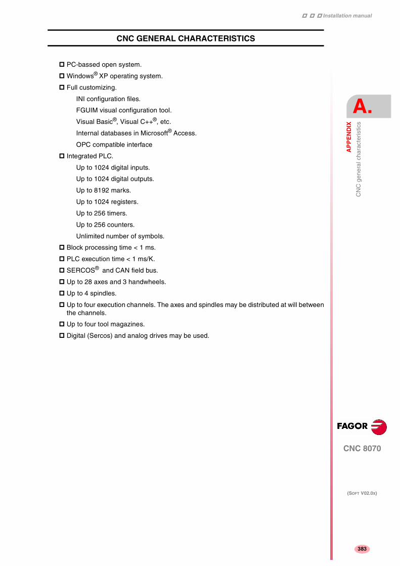
Installation manual
CNC 8070
AP
PE
ND
IX
CN
C g
ener
al c
hara
cter
istic
s
A.
(SOFT V02.0X)
383
CNC GENERAL CHARACTERISTICS
PC-bassed open system.
Windows® XP operating system.
Full customizing.
INI configuration files.
FGUIM visual configuration tool.
Visual Basic®, Visual C++®, etc.
Internal databases in Microsoft® Access.
OPC compatible interface
Integrated PLC.
Up to 1024 digital inputs.
Up to 1024 digital outputs.
Up to 8192 marks.
Up to 1024 registers.
Up to 256 timers.
Up to 256 counters.
Unlimited number of symbols.
Block processing time < 1 ms.
PLC execution time < 1 ms/K.
SERCOS® and CAN field bus.
Up to 28 axes and 3 handwheels.
Up to 4 spindles.
Up to four execution channels. The axes and spindles may be distributed at will betweenthe channels.
Up to four tool magazines.
Digital (Sercos) and analog drives may be used.

Installation manual
384
CNC 8070
A.
AP
PE
ND
IX
CN
C g
ener
al c
hara
cter
istic
s
(SOFT V02.0X)
384

Installation manual
CNC 8070
AP
PE
ND
IX
CN
C m
aint
enan
ce
B.
(SOFT V02.0X)
385
CNC MAINTENANCE
Cleaning
The accumulated dirt inside the unit may act as a screen preventing the proper dissipationof the heat generated by the internal circuitry which could result in a harmful overheating ofthe CNC and, consequently, possible malfunctions.
On the other hand, accumulated dirt can sometimes act as an electrical conductor andshortcircuit the internal circuitry, especially under high humidity conditions.
To clean the operator panel and the monitor, a smooth cloth should be used which has beendipped into de-ionized water and /or non abrasive dish-washer soap (liquid, never powder)or 75º alcohol.
Do not use highly compressed air to clean the unit because it could generate electrostaticdischarges.
The plastics used on the front panel are resistant to :
• Grease and mineral oils.
• Bases and bleach.
• Dissolved detergents.
• Alcohol.
• Avoid the action of solvents such as Chlorine hydrocarbons, Benzole, Esters and Etherwhich can damage the plastics used to make the unit’s front panel.
Preventive inspection
If the CNC does not turn on when actuating the start-up switch, verify the connections.
• Do not get into the inside of the unit.
Only personnel authorized by Fagor Automation may manipulate the inside of this unit.
• Do not handle the connectors with the unit connected to AC power.
Before handling these connectors (I/O, feedback, etc.), make sure that the unit is notconnected to main AC power.
Fagor Automation shall not be held responsible for any material or physical damage derivedfrom the violation of these basic safety requirements.

Installation manual
386
CNC 8070
B.
AP
PE
ND
IX
CN
C m
aint
enan
ce
(SOFT V02.0X)
386

Installation manual
CNC 8070
AP
PE
ND
IX
Sum
mar
y of
CN
C m
achi
ne p
aram
eter
s
C.
(SOFT V02.0X)
387
SUMMARY OF CNC MACHINE PARAMETERS
General machine parameters
Channel configuration.........................................................................................Page 13 NCHANNEL Number of channels
Axis configuration ...............................................................................................Page 13 NAXIS Number of axes governed by the CNC AXISNAME Name of each axis TANDEM Tandem axis TMASTERAXIS Tandem. Master or main axis TSLAVEAXIS Tandem. Slave axis TORQDIST Tandem. Torque distribution PRELOAD Tandem. Preload between both motors PRELFITI Tandem. Filter time to apply the preload TPROGAIN Tandem. Proportional gain (Kp) for the tandem axis TINTTIME Tandem. Integral gain (Kp) for the tandem axis TCOMPLIM Tandem. Compensation limit GANTRY Gantry axes MASTERAXIS Gantry. Master or main axis SLAVEAXIS Gantry. Slave axis WARNCOUPE Gantry. Maximum difference allowed to issue a warning MAXCOUPE Gantry. Maximum difference allowed DIFFCOMP Gantry. Difference compensation after G74 NSPDL Number of spindles governed by the CNC SPDLNAME Spindle name
Time setting..........................................................................................................Page 18 LOOPTIME CNC cycle (loop) time PRGFREQ Frequency of the PRG module (in cycles)
CAN and Sercos bus configuration....................................................................Page 19 SERBRATE Sercos transmission rate SERPOWSE Sercos optical power CANLENGTH CAN Bus cable length
Default conditions................................................................................................Page 20 INCHES Default work units (mm, inch)
Related to arithmetic parameters .......................................................................Page 20 MAXLOCP Maximum local arithmetic parameter MINLOCP Minimum local arithmetic parameter MAXGLBP Maximum global arithmetic parameter MINGLBP Minimum global arithmetic parameter ROPARMAX Maximum global read-only arithmetic parameter ROPARMIN Minimum global read-only arithmetic parameter MAXCOMP Maximum arithmetic parameter common to all the channels MINCOMP Minimum arithmetic parameter common to all the channels
Cross compensation ...........................................................................................Page 21 CROSSCOMP Cross compensation tables MOVAXIS Axis whose movement affects another axis (master) COMPAXIS Axis suffering the effects of the movement (compensated) NPCROSS Number of points in the table TYPCROSS Type of compensation BIDIR Bi-directional compensation REFNEED Mandatory home search DATA Table defining the compensation at each point POSITION Position of the master axis POSERROR Error in the positive direction NEGERROR Error in the negative direction
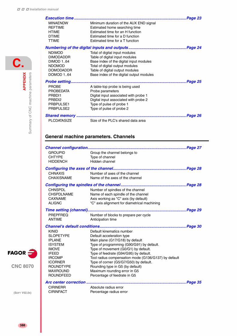
Installation manual
394
CNC 8070
C.
AP
PE
ND
IX
Sum
mar
y of
CN
C m
achi
ne p
aram
eter
s
(SOFT V02.0X)
388
Execution time .....................................................................................................Page 23 MINAENDW Minimum duration of the AUX END signal REFTIME Estimated home searching time HTIME Estimated time for an H function DTIME Estimated time for a D function TTIME Estimated time for a T function
Numbering of the digital inputs and outputs ....................................................Page 24 NDIMOD Total of digital input modules DIMODADDR Table of digital input modules DIMOD 1..64 Base index of the digital input modules NDOMOD Total of digital output modules DOMODADDR Table of digital output modules DOMOD 1..64 Base index of the digital output modules
Probe setting........................................................................................................Page 25 PROBE A table-top probe is being used PROBEDATA Probe parameters PRBDI1 Digital input associated with probe 1 PRBDI2 Digital input associated with probe 2 PRBPULSE1 Type of pulse of probe 1 PRBPULSE2 Type of pulse of probe 2
Shared memory ...................................................................................................Page 26 PLCDATASIZE Size of the PLC's shared data area
General machine parameters. Channels
Channel configuration.........................................................................................Page 27 GROUPID Group the channel belongs to CHTYPE Type of channel HIDDENCH Hidden channel
Configuring the axes of the channel..................................................................Page 28 CHNAXIS Number of axes of the channel CHAXISNAME Name of the axes of the channel
Configuring the spindles of the channel ...........................................................Page 28 CHNSPDL Number of spindles of the channel CHSPDLNAME Name of each spindle of the channel CAXNAME Axis working as "C" axis (by default) ALIGNC "C" axis alignment for diametrical machining
Time setting (channel).........................................................................................Page 29 PREPFREQ Number of blocks to prepare per cycle ANTIME Anticipation time
Channel's default conditions..............................................................................Page 30 KINID Default kinematics number SLOPETYPE Default acceleration type IPLANE Main plane (G17/G18) by default ISYSTEM Type of programming (G90/G91) by default. IMOVE Type of movement (G0/G1) by default. IFEED Type of feedrate (G94/G95) by default. IRCOMP Tool radius compensation mode (G136/G137) by default ICORNER Type of corner (G5/G7/G50) by default. ROUNDTYPE Rounding type in G5 (by default) MAXROUND Maximum rounding error in G5 ROUNDFEED Percentage of feedrate in G5
Arc center correction ..........................................................................................Page 35 CIRINERR Absolute radius error CIRINFACT Percentage radius error

Installation manual
CNC 8070
AP
PE
ND
IX
Sum
mar
y of
CN
C m
achi
ne p
aram
eter
s
C.
(SOFT V02.0X)
389
Feedrate override.................................................................................................Page 35 MAXOVR Maximum axis override (%) RAPIDOVR Override acts in G00 (from 0 to 100%) FEEDND Apply the programmed feedrate to all the axes of the channel IMOVEMACH Movement of the independent axis referred to machine coordinates
Related to subroutines ........................................................................................Page 37 SUBTABLE OEM-subroutines table TOOLSUB Name of the subroutine associated with T REFPSUB (G74) Subroutine associated with function G74 OEMSUB (G18x) Subroutines associated with functions G180 through G189 SUBPATH Path of program subroutines
Tabletop probe position ......................................................................................Page 38 PROBEDATA Channel related probe parameters PRB1MAX Maximum probe coordinate (abscissa axis) PRB1MIN Minimum probe coordinate (abscissa axis) PRB2MAX Maximum probe coordinate (ordinate axis) PRB2MIN Minimum probe coordinate (ordinate axis) PRB3MAX Maximum probe coordinate (axis perpendicular to the plane) PRB3MIN Minimum probe coordinate (axis perpendicular to the plane)
Machine parameters for the axes
Belonging to the channel ....................................................................................Page 40 AXISEXCH Channel changing permission . . . . . . . . . . . . . . . . . . . . . (L R S) (A S X)
Type of axis and drive .........................................................................................Page 40 AXISTYPE Type of axis . . . . . . . . . . . . . . . . . . . . . . . . . . . . . . . . . . . (L R S) (A S X) DRIVETYPE Drive type. . . . . . . . . . . . . . . . . . . . . . . . . . . . . . . . . . . . . (L R S) (A S X) SERCOSDATA SERCOS drive data. . . . . . . . . . . . . . . . . . . . . . . . . . . . . (L R S) (S) DRIVEID Sercos drive address . . . . . . . . . . . . . . . . . . . . . . . . . . . . (L R S) (S) OPMODEP Sercos drive operation mode. . . . . . . . . . . . . . . . . . . . . . (L R S) (S) FBACKSRC Type of feedback . . . . . . . . . . . . . . . . . . . . . . . . . . . . . . . (L R S) (S)
Hirth axis...............................................................................................................Page 41 HIRTH Hirth axis . . . . . . . . . . . . . . . . . . . . . . . . . . . . . . . . . . . . . (L R) (A S X) HPITCH Hirth axis pitch . . . . . . . . . . . . . . . . . . . . . . . . . . . . . . . . . (L R) (A S X)
Axis configuration for lathe type machines ......................................................Page 42 FACEAXIS Face axis (lathe) . . . . . . . . . . . . . . . . . . . . . . . . . . . . . . . (L) (A S X) LONGAXIS Longitudinal axis (lathe). . . . . . . . . . . . . . . . . . . . . . . . . . (L) (A S X)
Rotary axes...........................................................................................................Page 42 AXISMODE Operating mode of the rotary axis . . . . . . . . . . . . . . . . . . (R) (A S X) UNIDIR Unidirectional rotation . . . . . . . . . . . . . . . . . . . . . . . . . . . (R) (A S X) SHORTESTWAY Via shortest way . . . . . . . . . . . . . . . . . . . . . . . . . . . . . . . (R) (A S X)
Rotary axes and spindle......................................................................................Page 44 MODCOMP Module compensation . . . . . . . . . . . . . . . . . . . . . . . . . . . (R S) (A Ss X) CAXIS Works as a "C" axis . . . . . . . . . . . . . . . . . . . . . . . . . . . . . (R S) (A S X) CAXSET Work set for "C" axis . . . . . . . . . . . . . . . . . . . . . . . . . . . . (R S) (A S X)
Spindle ..................................................................................................................Page 44 AUTOGEAR Automatic gear change . . . . . . . . . . . . . . . . . . . . . . . . . . (S) (A S X) LOSPDLIM lower percentage for rpm OK. . . . . . . . . . . . . . . . . . . . . . (S) (A S X) UPSPDLIM Upper percentage for rpm OK . . . . . . . . . . . . . . . . . . . . . (S) (A S X) SPDLTIME Estimated time for an S function . . . . . . . . . . . . . . . . . . . (S) (A S X) SPDLSTOP M2, M30 and Reset stop the spindle . . . . . . . . . . . . . . . . (S) (A S X) SREVM05 G84. Reversal stops the spindle . . . . . . . . . . . . . . . . . . . (S) (A S X) STEPOVR Spindle Override step . . . . . . . . . . . . . . . . . . . . . . . . . . . (S) (A S X) MINOVR Minimum spindle override . . . . . . . . . . . . . . . . . . . . . . . . (S) (A S X) MAXOVR Maximum spindle override. . . . . . . . . . . . . . . . . . . . . . . . (S) (A S X)
Software axis limits .............................................................................................Page 46 LIMIT+ Positive software limit . . . . . . . . . . . . . . . . . . . . . . . . . . . (L R) (A S X) LIMIT- Negative software limit. . . . . . . . . . . . . . . . . . . . . . . . . . . (L R) (A S X) SWLIMITTOL Software limits tolerance . . . . . . . . . . . . . . . . . . . . . . . . . (L R) (A S X)

Installation manual
394
CNC 8070
C.
AP
PE
ND
IX
Sum
mar
y of
CN
C m
achi
ne p
aram
eter
s
(SOFT V02.0X)
390
Runaway protection.............................................................................................Page 46 TENDENCY Activation of tendency test . . . . . . . . . . . . . . . . . . . . . . . . (L R S) (A S)
PLC Offset ............................................................................................................Page 47 PLCOINC PLC offset increment per cycle. . . . . . . . . . . . . . . . . . . . . (L R S) (A S X)
Dwell for dead axes .............................................................................................Page 47 DWELL Dwell for dead axes . . . . . . . . . . . . . . . . . . . . . . . . . . . . . (L R S) (A S X)
Radius / diameter.................................................................................................Page 48 DIAMPROG Programming in diameters . . . . . . . . . . . . . . . . . . . . . . . . (L) (A S X)
Home search ........................................................................................................Page 48 REFDIREC Homing direction. . . . . . . . . . . . . . . . . . . . . . . . . . . . . . . . (L R S) (A S X) DECINPUT Availability of a home switch . . . . . . . . . . . . . . . . . . . . . . . (L R S) (A S)
Probe.....................................................................................................................Page 48 PROBEAXIS Probing axis . . . . . . . . . . . . . . . . . . . . . . . . . . . . . . . . . . . (L R) (A S X) PROBERANGE Maximum braking distance . . . . . . . . . . . . . . . . . . . . . . . . (L R) (A S X) PROBEFEED Maximum probing feedrate . . . . . . . . . . . . . . . . . . . . . . . . (L R) (A S X) PROBEDELAY Delay for the probe 1 signal . . . . . . . . . . . . . . . . . . . . . . . (L R) (A S X) PROBEDELAY2 Delay for the probe 2 signal . . . . . . . . . . . . . . . . . . . . . . . (L R) (A S X)
Repositioning of the axes in tool inspection ....................................................Page 49 REPOSFEED Maximum repositioning feedrate. . . . . . . . . . . . . . . . . . . . (L R) (A S X)
Independent axis .................................................................................................Page 50 POSFEED Positioning feedrate (independent axis) . . . . . . . . . . . . . . (L R S) (A S X) DSYNCVELW Velocity synchronization window. . . . . . . . . . . . . . . . . . . . (L R S) (A S X) DSYNCPOSW Position synchronization window . . . . . . . . . . . . . . . . . . . (L R S) (A S X)
Manual operating mode ......................................................................................Page 50 MANUAL Manual (jog) operating mode parameters. . . . . . . . . . . . . (L R) (A S X) MANPOSSW Maximum positive travel with G201 . . . . . . . . . . . . . . . . . (L R) (A S X) MANNEGSW Maximum negative travel with G201. . . . . . . . . . . . . . . . . (L R) (A S X) JOGFEED Continuous JOG mode feedrate . . . . . . . . . . . . . . . . . . . . (L R) (A S X) JOGRAPFEED Continuous rapid JOG mode feedrate . . . . . . . . . . . . . . . (L R) (A S X) MAXMANFEED Continuous maximum JOG mode feedrate. . . . . . . . . . . . (L R) (A S X) MAXMANACC Maximum acceleration in JOG mode . . . . . . . . . . . . . . . . (L R) (A S X) MANFEEDP Maximum % of jogging feedrate in G201 . . . . . . . . . . . . . (L R) (A S X) IPOFEEDP Maximum % of execution feedrate in G201 . . . . . . . . . . . (L R) (A S X) MANACCP Maximum % of jogging acceleration in G201 . . . . . . . . . . (L R) (A S X) IPOACCP Maximum % of execution acceleration in G201 . . . . . . . . (L R) (A S X)
Manual operating mode. Handwheels ...............................................................Page 52 MPGRESOL Handwheel resolution . . . . . . . . . . . . . . . . . . . . . . . . . . . . (L R) (A S X) MPGFILTER Filter time for the handwheel . . . . . . . . . . . . . . . . . . . . . . (L R) (A S X)
Manual operating mode. Incremetal JOG..........................................................Page 53 INCJOGDIST Incremental jog distances . . . . . . . . . . . . . . . . . . . . . . . . . (L R) (A S X) INCJOGFEED Incremental jog feedrates . . . . . . . . . . . . . . . . . . . . . . . . . (L R) (A S X)
Leadscrew error compensation .........................................................................Page 53 LSCRWCOMP Leadscrew error compensation . . . . . . . . . . . . . . . . . . . . (L R S) (A S X) LSCRWDATA Leadscrew compensation table . . . . . . . . . . . . . . . . . . . . (L R S) (A S X) NPOINTS Number of points of the table . . . . . . . . . . . . . . . . . . . . . . (L R S) (A S X) TYPLSCRW Type of compensation. . . . . . . . . . . . . . . . . . . . . . . . . . . . (L R S) (A S X) BIDIR Bi-directional compensation . . . . . . . . . . . . . . . . . . . . . . . (L R S) (A S X) REFNEED Mandatory home search. . . . . . . . . . . . . . . . . . . . . . . . . . (L R S) (A S X) DATA Leadscrew error compensation at each point . . . . . . . . . . (L R S) (A S X) POSITION Position of each point . . . . . . . . . . . . . . . . . . . . . . . . . . . . (L R S) (A S X) POSERROR Error in the positive direction . . . . . . . . . . . . . . . . . . . . . . (L R S) (A S X) NEGERROR Error in the negative direction. . . . . . . . . . . . . . . . . . . . . . (L R S) (A S X)
Filters to eliminate resonance frequency..........................................................Page 55 FILTER Filter table . . . . . . . . . . . . . . . . . . . . . . . . . . . . . . . . . . . . . (L R S) (A S X) ORDER Filter order . . . . . . . . . . . . . . . . . . . . . . . . . . . . . . . . . . . . (L R S) (A S X) TYPE Type of filter . . . . . . . . . . . . . . . . . . . . . . . . . . . . . . . . . . . (L R S) (A S X) FREQUENCY Break or mid frequency. . . . . . . . . . . . . . . . . . . . . . . . . . . (L R S) (A S X) NORBWIDTH Standard bandwidth . . . . . . . . . . . . . . . . . . . . . . . . . . . . . (L R S) (A S X) SHARE % of signal going through the filter . . . . . . . . . . . . . . . . . . (L R S) (A S X)

Installation manual
CNC 8070
AP
PE
ND
IX
Sum
mar
y of
CN
C m
achi
ne p
aram
eter
s
C.
(SOFT V02.0X)
391
Work sets ..............................................................................................................Page 58 NPARSETS Number of parameter sets . . . . . . . . . . . . . . . . . . . . . . . . (L R S) (A S X) DEFAULTSET Default work set . . . . . . . . . . . . . . . . . . . . . . . . . . . . . . . . (L R S) (A S X)
Machine parameters for the axes. Work sets
Resolution ............................................................................................................Page 59 PITCH Leadscrew pitch. . . . . . . . . . . . . . . . . . . . . . . . . . . . . . . . (L R S) (A S X) PITCH2 Leadscrew pitch (2nd feedback) . . . . . . . . . . . . . . . . . . . (L R S) (S) INPUTREV Turns of motor shaft . . . . . . . . . . . . . . . . . . . . . . . . . . . . . (L R S) (A S X) OUTPUTREV Turns of machine axis . . . . . . . . . . . . . . . . . . . . . . . . . . . (L R S) (A S X) INPUTREV2 Turns of motor shaft (2nd feedback) . . . . . . . . . . . . . . . . (L R S) (S) OUTPUTREV2 Turns of machine axis (2nd feedback) . . . . . . . . . . . . . . . (L R S) (S) NPULSES Number of encoder pulses. . . . . . . . . . . . . . . . . . . . . . . . (L R S) (A Ss X) NPULSES2 Number of encoder (2nd feedback) pulses . . . . . . . . . . . (L R S) (A Ss X) SINMAGNI Sinusoidal multiplying factor . . . . . . . . . . . . . . . . . . . . . . (L R S) (A X) ABSFEEDBACK Absolute feedback system. . . . . . . . . . . . . . . . . . . . . . . . (L R S) (A S X) FBACKAL Feedback alarm activation. . . . . . . . . . . . . . . . . . . . . . . . (L R S) (A)
Loop setting .........................................................................................................Page 61 LOOPCH Analog voltage sign change. . . . . . . . . . . . . . . . . . . . . . . (L R S) (A S X) AXISCH Feedback sign change. . . . . . . . . . . . . . . . . . . . . . . . . . . (L R S) (A S X) INPOSW In position zone . . . . . . . . . . . . . . . . . . . . . . . . . . . . . . . . (L R S) (A S X)
Backlash compensation in movement reversal ................................................Page 61 BACKLASH Backlash . . . . . . . . . . . . . . . . . . . . . . . . . . . . . . . . . . . . . (L R S) (A S X)
Backlash compensation with additional command pulse ...............................Page 62 BAKANOUT Additional command pulse. . . . . . . . . . . . . . . . . . . . . . . . (L R S) (A S) BAKTIME Duration of the additional command pulse . . . . . . . . . . . (L R S) (A S) ACTBAKAN Application of the additional command pulse . . . . . . . . . (L R S) (A S)
Feedrate setting ...................................................................................................Page 63 G00FEED Feedrate in G00. . . . . . . . . . . . . . . . . . . . . . . . . . . . . . . . (L R S) (A S X) MAXVOLT Analog voltage to reach G00FEED . . . . . . . . . . . . . . . . . (L R S) (A Ss)
Gain setting ..........................................................................................................Page 63 PROGAIN Proportional gain . . . . . . . . . . . . . . . . . . . . . . . . . . . . . . (L R S) (A S X) FFWTYPE Pre-control type . . . . . . . . . . . . . . . . . . . . . . . . . . . . . . . . (L R S) (A S X) FFGAIN Percentage of Feed-Forward in automatic. . . . . . . . . . . . (L R S) (A S X) MANFFGAIN Percentage of Feed-Forward in manual. . . . . . . . . . . . . . (L R S) (A X) ACFWFACTOR Acceleration time constant. . . . . . . . . . . . . . . . . . . . . . . . (L R S) (A Ss X) ACFGAIN Percentage of AC-Forward in automatic . . . . . . . . . . . . . (L R S) (A S X) MANACFGAIN Percentage of AC-Forward in JOG mode . . . . . . . . . . . . (L R S) (A X)
Linear acceleration ..............................................................................................Page 66 LACC1 Acceleration of the first section . . . . . . . . . . . . . . . . . . . . (L R S) (A S X) LACC2 Acceleration of the second section . . . . . . . . . . . . . . . . . (L R S) (A S X) LFEED Change speed . . . . . . . . . . . . . . . . . . . . . . . . . . . . . . . . . (L R S) (A S X)
Trapezoidal and square sine accelerations .......................................................Page 67 ACCEL Acceleration . . . . . . . . . . . . . . . . . . . . . . . . . . . . . . . . . . . (L R S) (A S X) DECEL Deceleration. . . . . . . . . . . . . . . . . . . . . . . . . . . . . . . . . . . (L R S) (A S X) ACCJERK Acceleration Jerk . . . . . . . . . . . . . . . . . . . . . . . . . . . . . . . (L R S) (A S X) DECJERK Acceleration Jerk . . . . . . . . . . . . . . . . . . . . . . . . . . . . . . . (L R S) (A S X)
Home search.........................................................................................................Page 69 I0TYPE Type of reference mark (I0) . . . . . . . . . . . . . . . . . . . . . . . (L R S) (A S X) REFVALUE Position of the reference point . . . . . . . . . . . . . . . . . . . . . (L R S) (A S X) REFSHIFT Offset of the reference point . . . . . . . . . . . . . . . . . . . . . . (L R S) (A S X) REFFEED1 Fast home searching feedrate . . . . . . . . . . . . . . . . . . . . . (L R S) (A S X) REFFEED2 Slow home searching feedrate . . . . . . . . . . . . . . . . . . . . (L R S) (A S X) REFPULSE Type of I0 pulse . . . . . . . . . . . . . . . . . . . . . . . . . . . . . . . . (L R S) (A S X) ABSOFF Offset referred to the distance-coded I0 . . . . . . . . . . . . . (L R S) (A S X) EXTMULT External factor for distance-coded mark . . . . . . . . . . . . . (L R S) (A X) I0CODDI1 Gap between two fixed distance-coded I0's . . . . . . . . . . (L R S) (A S X) I0CODDI2 Gap between two variable distance-coded I0's . . . . . . . . (L R S) (A S X)

Installation manual
394
CNC 8070
C.
AP
PE
ND
IX
Sum
mar
y of
CN
C m
achi
ne p
aram
eter
s
(SOFT V02.0X)
392
Following error.....................................................................................................Page 73 FLWEMONITOR Type of monitoring . . . . . . . . . . . . . . . . . . . . . . . . . . . . . . (L R S) (A S X) MINFLWE Maximum following error when stopped . . . . . . . . . . . . . . (L R S) (A S) MAXFLWE Maximum following error in motion . . . . . . . . . . . . . . . . . . (L R S) (A S) FEDYNAC % of following error deviation . . . . . . . . . . . . . . . . . . . . . . (L R S) (A S) ESTDELAY Following error delay. . . . . . . . . . . . . . . . . . . . . . . . . . . . . (L R S) (A S) INPOMAX Time to get in position. . . . . . . . . . . . . . . . . . . . . . . . . . . . (L R S) (A S X) INPOTIME Minimum in position time . . . . . . . . . . . . . . . . . . . . . . . . . (L R S) (A S X)
Axis lubrication....................................................................................................Page 75 DISTLUBRI Distance for lubrication pulse . . . . . . . . . . . . . . . . . . . . . . (L R S) (A S X)
Module definition in rotary axes and spindle....................................................Page 75 MODUPLIM Module's upper limit . . . . . . . . . . . . . . . . . . . . . . . . . . . . . (R S) (A Ss X) MODLOWLIM Module's lower limit. . . . . . . . . . . . . . . . . . . . . . . . . . . . . . (R S) (A Ss X) MODNROT Module error. Turns. . . . . . . . . . . . . . . . . . . . . . . . . . . . . . (R S) (A Ss X) MODERR Module error. Increments . . . . . . . . . . . . . . . . . . . . . . . . . (R S) (A Ss X)
Spindle..................................................................................................................Page 76 SZERO Speed considered "0 rpm" . . . . . . . . . . . . . . . . . . . . . . . . (S) (A X) POLARM3 Sign of the analog voltage for M3 . . . . . . . . . . . . . . . . . . . (S) (A Ss X) POLARM4 Sign of the analog voltage for M4 . . . . . . . . . . . . . . . . . . . (S) (A Ss X)
Analog voltage .....................................................................................................Page 77 SERVOOFF Offset compensation. . . . . . . . . . . . . . . . . . . . . . . . . . . . . (L R S) (A) MINANOUT Minimum analog output . . . . . . . . . . . . . . . . . . . . . . . . . . (L R S) (A)
Analog output / Feedback input .........................................................................Page 77 ANAOUTID Axis analog output . . . . . . . . . . . . . . . . . . . . . . . . . . . . . . (L R S) (A) COUNTERID Feedback input of the axis . . . . . . . . . . . . . . . . . . . . . . . . (L R S) (A)
Machine parameters for JOG mode
Handwheel configuration....................................................................................Page 78 NMPG Number of handwheels MANPG Table of handwheels COUNTERID Feedback input for the handwheel MPGAXIS Axis associated with the handwheel
Configuration of the JOG keys...........................................................................Page 79 JOGKEYDEF Axis and moving direction JOGTYPE JOG behavior
Machine parameters for the M function table
M function table ...................................................................................................Page 84 MTABLESIZE Number of table elements DATA M function table MNUM M function number SYNCHTYPE Type of synchronization MTIME Estimated time for an M function MPROGNAME Name of subroutine associated with M function
Machine parameters for kinetics
Kinematics............................................................................................................Page 87 NKIN Number of different kinematics KINEMATIC Kinematics table TYPE Kinematics type

Installation manual
CNC 8070
AP
PE
ND
IX
Sum
mar
y of
CN
C m
achi
ne p
aram
eter
s
C.
(SOFT V02.0X)
393
Definition of the spindle kinmatics (Types 1 through 8) ..................................Page 89 DATA1...DATA7 Spindle dimensions DATA8 Rest position of the main rotary axis DATA9 Rest position of the secondary rotary axis. DATA10 Turning direction of the main rotary axis DATA11 Turning direction of the secondary rotary axis DATA12 Manual rotary axes or servo-controlled DATA 13...DATA42 (Not being used at this time)
Definition of the table kinematics (Types 9 through 12)...................................Page 93 DATA1 (Not being used at this time) DATA2...DATA5 Table dimensions DATA6...DATA7 (Not being used at this time) DATA8 Rest position of the main rotary axis DATA9 Rest position of the secondary rotary axis. DATA10 Turning direction of the main rotary axis DATA11 Turning direction of the secondary rotary axis DATA12 Manual rotary axes or servo-controlled DATA 13...DATA42 (Not being used at this time)
Definition of the kinematics of the spindle - table (Types 13 through 16) ......Page 96 DATA1...DATA6 Spindle dimensions and table placement. DATA8 Rest position of the main rotary axis DATA9 Rest position of the secondary rotary axis. DATA10 Turning direction of the main rotary axis DATA11 Turning direction of the secondary rotary axis DATA12 Manual rotary axes or servo-controlled DATA 13...DATA15 Spindle placement DATA16...DATA42 (Not being used at this time)
Definition of the C axis kinematics (Types 41 through 43) ..............................Page 100 DATA2 Rotary axis position
Machine parameters for the magazine
Tool magazine configuration ..............................................................................Page 101 NTOOLMZ Number of tool magazines GROUND Ground tools are permitted (manual load) MAGAZINE Tool magazine table
Storage data .........................................................................................................Page 101 STORAGE Parameters related to storage SIZE Size of the magazine (number of pockets) RANDOM Random magazine
Tool magazine management ...............................................................................Page 102 MANAGEMENT Management related parameters TYPE Magazine type CYCLIC Cyclic tool changer OPTIMIZE Tool management. M6ALONE Action when executing an M06 without selecting a T

Installation manual
394
CNC 8070
C.
AP
PE
ND
IX
Sum
mar
y of
CN
C m
achi
ne p
aram
eter
s
(SOFT V02.0X)
394
Machine parameters for HMI (Interface)
Customizing .........................................................................................................Page 106 WINDOW Dimensions of the main window POSX X coordinate of the top left corner POSY Y coordinate of the top left corner WIDTH Width of the window HEIGHT Height of the window VMENU Position of the vertical softkey-menu LANGUAGE Work language USERKEY Customizing the user key FUNCTION Function of the user key COMPONENT Access a component without a hotkey APPLICATION Execute a PC application CHANGEKEY Customizing the change key FUNCTION Function of the change key MENU Set up the system menu SYSMENUMODE Behavior of the system menu SYSHMENU Horizontal system-menu SYSVMENU Vertical system-menu ESCAPEKEY Customizing the escape key FUNCTION Function associated with the escape key NPREVIOUS Maximum number of previous components stored. SIMJOGPANEL Simulated JOG panel WINEXIT Exit Windows when closing the CNC DIAGPSW (Reserved)
OEM machine parameters
Reading drive variables ......................................................................................Page 110 DRIVEVAR Drive variables table SIZE Number of variables to consulted at the drive DATA List of drive variables MNEMONIC Name of the variable at the drive AXIS Axis or spindle that the variable belongs to ID Variable identifier at the drive TYPE Access type MODE Access mode
Generic OEM-parameters....................................................................................Page 111 MTBPAR OEM-parameter table SIZE Number of OEM parameters DATA OEM parameters
Cam editor............................................................................................................Page 111 CAMTABLE Table of electronic cams SIZE Number of electronic cams DATA Cam data CAM1..16 Electronic-cam editor

Installation manual
CNC 8070
AP
PE
ND
IX
Sum
mar
y of
PLC
pro
gram
min
g co
mm
ands
D.
(SOFT V02.0X)
395
SUMMARY OF PLC PROGRAMMING COMMANDS
RESOURCES AVAILABLE AT THE PLC
Inputs (I1··1024)
Outputs (O1··1024)
Marks (M1··8192)
Message marks (MSG1··256)
Error marks (ERR1··256)
Clocks (CLK)
CNC-PLC marks
Timers (T1··256)
Counters (C1··256)
Registers (R1··1024)
CNC-PLC registers
The register value may be treated as a decimal or hexadecimal ("S") number.
It is also possible to refer to a register bit using the letter B (0··31) R (1··1024).
DIRECTING INSTRUCTIONS
PRG Main module
PE t Periodic module. It is executed every "t" milliseconds.
CY1 First Cycle module.
END End of module.
L Label
SUB Subroutine definition.
DEF Symbol definition.
PDEF External symbol definition.
REA The consultations will use real values.
IMA The consultations will use image values.
NOMONIT No PLC program monitoring.
EXTERN External subroutine definition.
CLK1 1ms CLK100 100ms CLK1000 1s
CLK2 2ms CLK200 200ms CLK2000 2s
CLK4 4ms CLK400 400ms CLK4000 4s
CLK8 8ms CLK800 800ms CLK8000 8s
CLK16 16ms CLK1600 1.6s CLK16000 16s
CLK32 32ms CLK3200 3.2s CLK32000 32s
CLK64 64ms CLK6400 6.4s CLK64000 64s
CLK128 128ms CLK12800 12.8s CLK128000 128s

Installation manual
400
CNC 8070
D.
AP
PE
ND
IX
Sum
mar
y of
PLC
pro
gram
min
g co
mm
ands
(SOFT V02.0X)
396
CONSULTING INSTRUCTIONS
Simple consulting instructions.
I1··1024 Inputs
O1··1024 Outputs
M1··8192 Marks
MSG1··256 Messages
ERR1··256 Errors
T1··256 Timers (status)
C1··256 Counters (status)
B0··31 R1··1024 Register bit
CLK Clocks
M <CNC-PLC> Marks for CNC-PLC communication
Flank detection instructions.
DFU Up flank detection.
DFD Down flank detection.
Comparing instructions.
CPS For comparisons.
OPERATORS
NOT Negates the result of the consultation.
AND Logic function "AND".
OR Logic function "OR”.
XOR Logic "Exclusive OR" function.
\ Line feed.
( ) Consulting instruction whose value is always "1".
DFU
DFD
I1··1024
O1··1024
M1··8192
MSG1··256
ERR1··256
B0··31 R1··1024
CLK
M <CNC-PLC>
CPS T1··256
C1··256
R1··1024
R CNC-PLC
#
GT
GE
EQ
NE
LE
LT
T1··256
C1··256
R1··1024
R CNC-PLC
#

Installation manual
CNC 8070
AP
PE
ND
IX
Sum
mar
y of
PLC
pro
gram
min
g co
mm
ands
D.
(SOFT V02.0X)
397
ACTION INSTRUCTION.
Assignment binary action instructions.
Conditional binary action instructions.
= SET If expression = "1", it sets the resource to "1".
= RES If expression = "1", it sets the resource to "0".
= CPL If expression = "1", it complements the resource.
Sequence breaking action instructions.
= JMP L Unconditional jump.
= CAL Call to a subroutine.
= RET Return or end of a subroutine.
Arithmetic action instructions.
= MOV Move.
= I 1/1024 = O 1/1024 = M 1/8192= MSG 1/256 = ERR 1/256 = TEN 1/256= TRS 1/256 = TGn 1/256 #/R = CUP 1/256= CDW 1/256 = CEN 1/256 = CPR 1/256 #/R= B 0/31 R 1/499 = CNC-PLC mark
= SET
= RES
= CPL
I1··1024
O1··1024
M1··8192
MSG1··256
ERR1··256
B0··31 R1··1024
M <CNC-PLC>
Origin Destination Origin code
Destination code
Bits to transmit
= MOV I1/1024
O1/1024M1/8192MSG1/256ERR1/256T1/256C1/256
R1/1024R <CNC-PLC>#
I1/1024
O1/1024M1/8192MSG1/256ERR1/256R1/1024R <CNC-PLC>
0(Bin)
1(BCD)
0(Bin)
1(BCD)
32
28242016128
4

Installation manual
400
CNC 8070
D.
AP
PE
ND
IX
Sum
mar
y of
PLC
pro
gram
min
g co
mm
ands
(SOFT V02.0X)
398
= NGU R1··1024 Complements the bits of a register.
= NGS R1··1024 Register sign change.
= ADS Add.
= SBS Substract.
= MLS Multiplication.
= DVS Division.
= MDS Module or remainder of a division.
Logic action instructions.
= AND Logic operation "AND".
= OR Logic operation "OR".
= XOR Logic operation "XOR".
= RR 1/2 Right-hand register rotation.
= RL 1/2 Left-hand register rotation.
Specific action instructions.
= ERA Erases or resets a group of resources.
Operand Operand Result
= ADS= SBS= MLS= DVS= MDS
R1··1024R <CNC-PLC>#
R1··1024R <CNC-PLC>#
R1··1024R <CNC-PLC>
= AND= OR= XOR
R1··1024R <CNC-PLC>#
R1··1024R <CNC-PLC>#
R1··1024R <CNC-PLC>
Origin Repetion Nr. Destination
= ADS= SBS= MLS= DVS= MDS
R1··1024R <CNC-PLC>
R1··1024R <CNC-PLC>0··31
R1··1024R <CNC-PLC>
= ERA I1··1024O1··1024M1··8192MSG1··256ERR1··256T1··256
C1··256R1··1024
1··10241··10241··81921··2561··2561··256
1··2561··1024

Installation manual
CNC 8070
AP
PE
ND
IX
Sum
mar
y of
PLC
pro
gram
min
g co
mm
ands
D.
(SOFT V02.0X)
399
=CNCRD Reading of internal variables.
CNCRD (Variable, R1··1024, M1··8192)
=CNCWR Writing of internal variables.
CNCRD (Variable, R1··1024, M1··8192)
=PAR Parity of a register.
Action instructions of the electronic cam
= CAM ON Activate de electronic cam
CAM ON (cam, master/"TIME", slave, master_off, slave_off, range_master, range_slave, type)
= CAM OFF Cancel de electronic cam
CAM OFF (slave)
Actions instructions for independent axes
= MOVE ABS Absolute positioning move.
MOVE ABS (axis, pos, feed, blend)
= MOVE ADD Incremental positioning move.
MOVE ADD (axis, pos, feed, blend)
= MOVE INF Infinite (endless) positioning move.
MOVE INF (axis, direction, feed, blend)
= FOLLOW ON Activates the synchronization movement.
FOLLOW ON (master, slave, nratio, dratio, synctype)
= FOLLOW OFF Cancels the synchronization movement.
FOLLOW OFF (slave)
= PAR R1··1024R CNC-PLC
M1··8192MSG1··256ERR1··256
M CNC-PLC

Installation manual
400
CNC 8070
D.
AP
PE
ND
IX
Sum
mar
y of
PLC
pro
gram
min
g co
mm
ands
(SOFT V02.0X)
400

Installation manual
CNC 8070
AP
PE
ND
IX
Logi
c C
NC
inpu
ts a
nd o
utpu
ts
E.
(SOFT V02.0X)
401
LOGIC CNC INPUTS AND OUTPUTS
CONSULTATION - GENERAL
CONSULTATION - AXES AND SPINDLES
CNCREADY (M) The CNC is ready (No problems).START (M) The CYCLE START key has been pressed.FHOUT (M) The execution of the program is stopped.RESETOUT (M) A Reset has occurred (by key or by PLC).
_ALARM (M) Alarm or emergency generated by the CNC.MANUAL (M) Manual operating mode selected.AUTOMAT (M) Automatic operating mode selected.MDI (M) MDI mode selected.SBOUT (M) Single-block mode selected.INCYCLE (M) Block in execution or axis in motion.
RAPID (M) Rapid positioning (traverse, G0).ZERO (M) Home search (G74).PROBE (M) Probing (G100).THREAD (M) Threading (G33).TAPPING (M) Tapping canned cycle (G84).RIGID (M) Rigid tapping (G63).
CSS (M) Constant Surface Speed (G96).MFUN1..7 (R) Auxiliary M functions.MSTROBE (M) Execute auxiliary M function.HFUN1..7 (R) Auxiliary H functions.HSTROBE (M) Execute auxiliary H function.SFUN1 (R) Selected spindle speed.
SSTROBE (M) Select new spindle speed.INTEREND (M) Theoretical movement ended.INPOS (M) All axes in position.DMxx (M) Mxx in the program history.BLKSEARCH (M) "Block search" option.ADVINPOS (M) Anticipation signal for axes in position.
FREE (M) CNC ready to accept a block using CNCEX.WAITOUT (M) The CNC is waiting for a synchronization signal from a channel.SYNC (R) Spindle to be used for synchronization.MMCWDG (M) Status of the operating system.
ENABLE(axis) (M) Enable axis or spindle movement.DIR(axis) (M) Axis moving in the negative direction.REFPOIN(axis) (M) Home search done.DRSTAF(axis) (M) With Sercos. Drive statusDRSTAS(axis) (M) With Sercos. Drive status
INPOS(axis) (M) Axis or spindle in position.LUBR(axis) (M) The axis or spindle must be lubricated.HIRTHON(axis) (M) Axis working as Hirth axis.MATCH(axis) (M) Hirth axis positioned properly.PARK(axis) (M) Park the axis.UNPARK(axis) (M) Unpark the axis.

Installation manual
404
CNC 8070
E.
AP
PE
ND
IX
Logi
c C
NC
inpu
ts a
nd o
utpu
ts
(SOFT V02.0X)
402
CONSULTATION - SPINDLE
CONSULTATION - INDEPENDENT INTERPOLATOR
CONSULTATION - TOOL MANAGER
CONSULTATION - KEYS
MODIFIABLE - GENERAL
CAXIS (M) Spindle working as "C" axis.REVOK (M) Real revolutions = programmed.
IBUSY(axis) (M) There is an instruction pending execution.IFREE(axis) (M) The PLC is ready to accept a motion block.IFHOUT(axis) (M) The execution is interrupted.IEND(axis) (M) The final position has been reached.INSYNC(axis) (M) Synchronism has been reached.
TMOPERATION (R) Type of operation.TMOPSTROBE (M) Execute operation indicated in TMOPERATION.LEAVEPOS (R) Magazine position to leave the tool.TAKEPOS (R) Magazine position to pick up the tool.
NEXTPOS (R) Magazine position for next tool.TWORNOUT (M) Rejected tool (worn out, real life > max.).TMINEM (M) Emergency of tool manager.MZID (R) Magazine containing the requested tool.
KEYBD1, 2 (R) Indicate which key has been pressed.
_EMERGEN (M) Stops (=0) axis feed and spindle speed. It displays an error messageon the screen.
_STOP (M) Stops (=0) part program execution and keeps the spindle turning.
_FEEDHOL (M) Stops (=0) axis feed temporarily and keeps the spindle turning._XFERINH (M) Inhibits (=0) the execution of the next block, but it ends the one that
is being executed.CYSTART (M) Start (=1) program execution.SBLOCK (M) Operate (=1) in Single block mode.MANRAPID (M) Rapid jog (=1).OVRCAN (M) Set (=1) feedrate at 100%.LATCHM (M) JOG keys. The axis moves while the key is pressed (=0) or until
another one is pressed (=1).RESETIN (M) Assume (up flank) the machining conditions set by machine
parameters.AUXEND (M) M and S function management.
TIMERON (M) Enable timer (=1).PLCREADY (M) PLC ready (=1).BLKSKIP1 (M) Do not execute (=1) blocks with block skip indicator "/”.M01STOP (M) Do not ignore (=1) conditional stop (M01).NOWAIT (M) It cancels the synchronizations with the channel.DISCROSS1..9 (M) It disables the cross compensation table.

Installation manual
CNC 8070
AP
PE
ND
IX
Logi
c C
NC
inpu
ts a
nd o
utpu
ts
E.
(SOFT V02.0X)
403
MODIFIABLE - AXES AND SPINDLES
MODIFIABLE - SPINDLE
MODIFIABLE - INDEPENDENT INTERPOLATOR
LIMITPOS(axis) (M) Positive limit overrun (=1).LIMITNEG(axis) (M) Negative limit overrun (=1).DECEL(axis) (M) Change (=1) home searching feedrate from fast to slow.INHIBIT(axis) (M) Inhibit (=1) axis or spindle movement.AXISPOS(axis) (M) Movement (=1) in the positive direction in JOG mode.
AXISNEG(axis) (M) Movement (=1) in the negative direction in JOG mode.SERVO(axis)ON (M) Enable (=1) axis or spindle movement. When (=0), it stops the axis
and the spindle displaying an error message.DRO(axis) (M) When (=1) and SERVOnON (=0) it works as a DRO (open loop and
ignoring the following error).SPENA(axis) (M) "Speed enable" signal of the drive (Sercos).DRENA(axis) (M) "Drive enable" signal of the drive (Sercos).LIM(axis)OFF (M) Ignore (=1) software limits set with G198 and G199.PARKED(axis) (M) The axis is parked (=1).LUBRENA(axis) (M) Use (=1) axis lubricating feature.
LUBROK(axis) (M) Axis lubrication done (=1).DIFFCOMP(axis) (M) Correct the coordinate difference between the two axes of a Gantry
axis.
SPDLEREV (M) Reverse (=1) spindle turning direction.GEAR1,2,3,4 (M) Selected gear (=1).
PLCCNTL (M) Spindle controlled by the PLC (=1).SANALOG (R) Spindle analog voltage to be applied.
IRESET(axis) (M) It interrupts the running independent-axis instruction and eliminatesthe pending instructions. It interrupts cam synchronization.It sets the initial conditions at the interpolator.
IABORT(axis) (M) It interrupts the running positioning movement and eliminates thepending positioning movements.

Installation manual
404
CNC 8070
E.
AP
PE
ND
IX
Logi
c C
NC
inpu
ts a
nd o
utpu
ts
(SOFT V02.0X)
404
MODIFIABLE - TOOL MANAGER
MODIFIABLE - KEYS
SETTMEM (M) Activate (=1) Tool manager emergency.RESTMEM (M) Cancel (=0) tool manager emergency.CUTTINGON (M) Tool in execution (=1).TREJECT (M) The tool must be rejected (=1).MZTOCH1 (M) (=1) Tool taken from magazine to changer arm 1.
CH1TOSPDL (M) (=1) Tool taken from changer arm 1 to the spindle.SPDLTOCH1 (M) (=1) Tool taken from spindle to tool changer arm 1.SPDLTOCH2 (M) (=1) Tool taken from spindle to tool changer arm 2.CH1TOMZ (M) (=1) Tool taken from changer arm 1 to the magazine.CH2TOMZ (M) (=1) Tool taken from changer arm 2 to the magazine.SPDLTOGR (M) (=1) Tool taken from the spindle to ground.
GRTOSPDL (M) (=1) Tool taken from ground to the spindle.MZTOSPDL (M) (=1) Tool taken from magazine to spindle.SPDLTOMZ (M) (=1) Tool taken from spindle to magazine.MZROT (M) The turret has been rotated (=1).TCHANGEOK (M) Tool change done (=1).MZPOS (R) Current tool magazine position.
KEYLED1, 2 (R) Turn the key lights on (=1).KEYDIS1, 2, 3 (R) Inhibit keys (=1).

Installation manual
CNC 8070
AP
PE
ND
IX
Sum
mar
y of
CN
C v
aria
bles
F.
(SOFT V02.0X)
405
SUMMARY OF CNC VARIABLES
Related to general machine parameters
Channel configuration.........................................................................................Page 332(V.)MPG.NCHANNEL Number of CNC channels.
Axis configuration ...............................................................................................Page 332(V.)MPG.NAXIS Number of axes governed by the CNC(V.)MPG.AXISNAMEx Name of the "n" logic axis(V.)MPG.TMASTERAXIS[i] Tandem [i]. Logic number of the master axis(V.)MPG.TSLAVEAXIS[i] Tandem [i]. Logic number of the slave axis(V.)MPG.TORQDIST[i] Tandem [i]. Torque distribution(V.)MPG.PRELOAD[i] Tandem [i]. Preload(V.)MPG.PRELFITI[i] Tandem [i]. Time to apply the preload(V.)MPG.TPROGAIN[i] Tandem [i]. Proportional gain(V.)MPG.TINTIME[i] Tandem [i]. Integral gain(V.)MPG.TCOMPLIM[i] Tandem [i]. Compensation Limit(V.)MPG.MASTERAXIS[i] Gantry [i]. Logic number of the master axis(V.)MPG.SLAVEAXIS[i] Gantry [i]. Logic number of the slave axis(V.)MPG.WARNCOUPE[i] Gantry [i]. Maximum difference to issue a warning(V.)MPG.MAXCOUPE[i] Gantry [i]. Maximum difference allowed(V.)MPG.DIFFCOMP[i] Gantry [i]. Error difference compensation.
Spindle configuration ..........................................................................................Page 332(V.)MPG.NSPDL Number of spindles governed by the CNC(V.)MPG.SPDLNAMEx Name of the "x" spindle
Time setting..........................................................................................................Page 332(V.)MPG.LOOPTIME Loop time(V.)MPG.PRGFREQ Frequency of the PRG module (in cycles)
CAN and Sercos bus configuration....................................................................Page 332(V.)MPG.SERBRATE Sercos transmission speed(V.)MPG.SERPOWSE Sercos optical power(V.)MPG.CANLENGTH Can bus cable length (in meters)
Default conditions................................................................................................Page 332(V.)MPG.INCHES Default work units
Related to arithmetic parameters .......................................................................Page 333(V.)MPG.MAXLOCP Maximum local arithmetic parameter(V.)MPG.MINLOCP Minimum local arithmetic parameter(V.)MPG.MAXGLBP Maximum global arithmetic parameter(V.)MPG.MINGLBP Minimum global arithmetic parameter(V.)MPG.ROPARMAX Maximum global read-only arithmetic parameter(V.)MPG.ROPARMIN Minimum global read-only arithmetic parameter(V.)MPG.MAXCOMP Maximum common arithmetic parameter(V.)MPG.MINCOMP Maximum common arithmetic parameter
Cross compensation table ..................................................................................Page 333(V.)MPG.MOVAXIS[m] Table [m]. Master axis(V.)MPG.COMPAXIS[m] Table [m]. Axis to be compensated(V.)MPG.NPCROSS[m] Table [m]. Number of points(V.)MPG.TYPCROSS[m] Table [m]. Type of compensation(V.)MPG.BIDIR[m] Table [m]. Bi-directional compensation(V.)MPG.REFNEED[m] Table [m]. Mandatory home search(V.)MPG.POSITION[m][i] Table [m]. Master axis position for point [i](V.)MPG.POSERROR[m][i] Table [m]. Error of point [i] in the positive direction(V.)MPG.NEGERROR[m][i] Table [m]. Error of point [i] in the negative direction
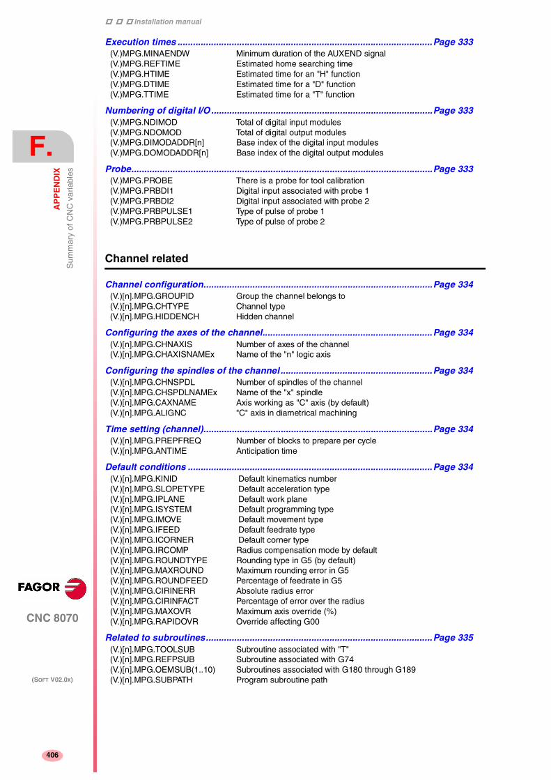
Installation manual
420
CNC 8070
F.
AP
PE
ND
IX
Sum
mar
y of
CN
C v
aria
bles
(SOFT V02.0X)
406
Execution times ...................................................................................................Page 333(V.)MPG.MINAENDW Minimum duration of the AUXEND signal(V.)MPG.REFTIME Estimated home searching time(V.)MPG.HTIME Estimated time for an "H" function(V.)MPG.DTIME Estimated time for a "D" function(V.)MPG.TTIME Estimated time for a "T" function
Numbering of digital I/O ......................................................................................Page 333(V.)MPG.NDIMOD Total of digital input modules(V.)MPG.NDOMOD Total of digital output modules(V.)MPG.DIMODADDR[n] Base index of the digital input modules(V.)MPG.DOMODADDR[n] Base index of the digital output modules
Probe.....................................................................................................................Page 333(V.)MPG.PROBE There is a probe for tool calibration(V.)MPG.PRBDI1 Digital input associated with probe 1(V.)MPG.PRBDI2 Digital input associated with probe 2(V.)MPG.PRBPULSE1 Type of pulse of probe 1(V.)MPG.PRBPULSE2 Type of pulse of probe 2
Channel related
Channel configuration.........................................................................................Page 334(V.)[n].MPG.GROUPID Group the channel belongs to(V.)[n].MPG.CHTYPE Channel type(V.)[n].MPG.HIDDENCH Hidden channel
Configuring the axes of the channel..................................................................Page 334(V.)[n].MPG.CHNAXIS Number of axes of the channel(V.)[n].MPG.CHAXISNAMEx Name of the "n" logic axis
Configuring the spindles of the channel ...........................................................Page 334(V.)[n].MPG.CHNSPDL Number of spindles of the channel(V.)[n].MPG.CHSPDLNAMEx Name of the "x" spindle(V.)[n].MPG.CAXNAME Axis working as "C" axis (by default)(V.)[n].MPG.ALIGNC "C" axis in diametrical machining
Time setting (channel).........................................................................................Page 334(V.)[n].MPG.PREPFREQ Number of blocks to prepare per cycle(V.)[n].MPG.ANTIME Anticipation time
Default conditions ...............................................................................................Page 334(V.)[n].MPG.KINID Default kinematics number(V.)[n].MPG.SLOPETYPE Default acceleration type(V.)[n].MPG.IPLANE Default work plane(V.)[n].MPG.ISYSTEM Default programming type(V.)[n].MPG.IMOVE Default movement type(V.)[n].MPG.IFEED Default feedrate type(V.)[n].MPG.ICORNER Default corner type(V.)[n].MPG.IRCOMP Radius compensation mode by default(V.)[n].MPG.ROUNDTYPE Rounding type in G5 (by default)(V.)[n].MPG.MAXROUND Maximum rounding error in G5(V.)[n].MPG.ROUNDFEED Percentage of feedrate in G5(V.)[n].MPG.CIRINERR Absolute radius error(V.)[n].MPG.CIRINFACT Percentage of error over the radius(V.)[n].MPG.MAXOVR Maximum axis override (%)(V.)[n].MPG.RAPIDOVR Override affecting G00
Related to subroutines........................................................................................Page 335(V.)[n].MPG.TOOLSUB Subroutine associated with "T"(V.)[n].MPG.REFPSUB Subroutine associated with G74(V.)[n].MPG.OEMSUB(1..10) Subroutines associated with G180 through G189(V.)[n].MPG.SUBPATH Program subroutine path

Installation manual
CNC 8070
AP
PE
ND
IX
Sum
mar
y of
CN
C v
aria
bles
F.
(SOFT V02.0X)
407
Probe.....................................................................................................................Page 335(V.)[n].MPG.PRB1MIN Minimum probe coordinate along the abscissa axis(V.)[n].MPG.PRB1MAX Maximum probe coordinate along the abscissa axis(V.)[n].MPG.PRB2MIN Minimum probe coordinate along the ordinate axis(V.)[n].MPG.PRB2MAX Maximum probe coordinate along the ordinate axis(V.)[n].MPG.PRB3MIN Minimum probe coordinate along the axis perpendicular to the plane(V.)[n].MPG.PRB3MAX Maximum probe coordinate along the axis perpendicular to the plane
Related to axis machine parameters
Belonging to the channel ....................................................................................Page 336(V.)[n].MPA.AXISEXCH Channel change permission
Type of axis and drive .........................................................................................Page 336(V.)[n].MPA.DRIVETYPE.Xn Type of drive(V.)[n].MPA.AXISTYPE.Xn Type of axis(V.)[n].MPA.DRIVEID.Xn Sercos drive select (ID)(V.)[n].MPA.OPMODEP.Xn Sercos drive operating mode(V.)[n].MPA.FBACKSRC.Xn Type of axis
Hirth axis...............................................................................................................Page 336(V.)[n].MPA.HIRTH.Xn Hirth axis(V.)[n].MPA.HPITCH.Xn Hirth axis pitch
Axis configuration for lathe type machines ......................................................Page 336(V.)[n].MPA.FACEAXIS.Xn Face axis(V.)[n].MPA.LONGAXIS.Xn Longitudinal axis
Rotary axes...........................................................................................................Page 336(V.)[n].MPA.AXISMODE.Xn Work mode(V.)[n].MPA.UNIDIR.Xn Unidirectional rotation(V.)[n].MPA.SHORTESTWAY.Xn Via shortest way
Rotary axes and spindle......................................................................................Page 336(V.)[n].MPA.MODCOMP.Xn Module compensation(V.)[n].MPA.CAXIS.Xn Works as a "C" axis(V.)[n].MPA.CAXSET.Xn Work set for "C" axis
Spindle ..................................................................................................................Page 337(V.)[n].MPA.AUTOGEAR.Xn Automatic gear change(V.)[n].MPA.LOSPDLIM.Xn Lower "rpm OK" percentage(V.)[n].MPA.UPSPDLIM.Xn Upper "rpm OK" percentage(V.)[n].MPA.SPDLTIME.Xn Estimated time for an S function(V.)[n].MPA.SPDLSTOP.Xn M2, M30 and Reset stop the spindle(V.)[n].MPA.SREVM05.Xn G84. Reversal stops the spindle(V.)[n].MPA.STEPOVR.Xn Override step(V.)[n].MPA.MINOVR.Xn Minimum override (%)(V.)[n].MPA.MAXOVR.Xn Maximum override (%)
Software axis limits .............................................................................................Page 337(V.)[n].MPA.POSLIMIT.Xn Positive software limit(V.)[n].MPA.NEGLIMIT.Xn Negative software limit(V.)[n].MPA.SWLIMITTOL.Xn Software limit tolerance
Runaway protection.............................................................................................Page 337(V.)[n].MPA.TENDENCY.Xn Activation of tendency test
PLC offset .............................................................................................................Page 337(V.)[n].MPA.PLCOINC.Xn PLC offset increment per cycle
Dwell for dead axes..............................................................................................Page 337(V.)[n].MPA.DWELL.Xn Dwell for dead axes
Radius / diameter .................................................................................................Page 337(V.)[n].MPA.DIAMPROG.Xn Programming in diameters
Home search.........................................................................................................Page 337(V.)[n].MPA.REFDIREC.Xn Home search direction(V.)[n].MPA.DECINPUT.Xn Home switch

Installation manual
420
CNC 8070
F.
AP
PE
ND
IX
Sum
mar
y of
CN
C v
aria
bles
(SOFT V02.0X)
408
Probe.....................................................................................................................Page 337(V.)[n].MPA.PROBEAXIS.Xn Probing axis(V.)[n].MPA.PROBERANGE.Xn Maximum braking distance(V.)[n].MPA.PROBEFEED.Xn Probing feedrate(V.)[n].MPA.PROBEDELAY Delay for the "probe 1" signal(V.)[n].MPA.PROBEDELAY Delay for the "probe 2" signal
Tool inspection ....................................................................................................Page 337(V.)[n].MPA.REPOSFEED.Xn Maximum repositioning feedrate
Independent axis .................................................................................................Page 337(V.)[n].MPA.POSFEED.Xn Positioning feedrate(V.)[n].MPA.DSYNCVELW.Xn Velocity synchronization window(V.)[n].MPA.DSYNCPOSW.Xn Position synchronization window
JOG mode.............................................................................................................Page 338(V.)[n].MPA.MANPOSSW.Xn Maximum positive travel with G201(V.)[n].MPA.MANNEGSW.Xn Maximum negative travel with G201(V.)[n].MPA.JOGFEED.Xn Continuous JOG mode feedrate(V.)[n].MPA.JOGRAPFEED.Xn Rapid feed in continuous JOG mode(V.)[n].MPA.MAXMANFEED.Xn Maximum feed in continuous JOG(V.)[n].MPA.MAXMANACC.Xn Maximum acceleration in JOG mode(V.)[n].MPA.MANFEEDP.Xn Maximum % of jog feedrate with G201(V.)[n].MPA.IPOFEEDP.Xn Maximum % of execution feedrate with G201(V.)[n].MPA.MANACCP.Xn Maximum % of jog acceleration with G201(V.)[n].MPA.IPOACCP.Xn Maximum % of execution acceleration with G201
JOG mode. Handwheels .....................................................................................Page 338(V.)[n].MPA.MPGRESOL[i].Xn Dial resolution at the [i] position(V.)[n].MPA.MPGFILTER.Xn Filter time for the handwheel
JOG mode. Incremental JOG..............................................................................Page 338(V.)[n].MPA.INCJOGDIST[i].Xn Moving distance at [i] dial position(V.)[n].MPA.INCJOGFEED[i].Xn Feedrate at [i] position
Leadscrew error compensation .........................................................................Page 338(V.)[n].MPA.LSCRWCOMP.Xn Leadscrew error compensation(V.)[n].MPA.NPOINTS.Xn Number of points in the table(V.)[n].MPA.TYPLSCRW.Xn Type of compensation(V.)[n].MPA.BIDIR.Xn Bi-directional compensation(V.)[n].MPA.REFNEED.Xn Mandatory home search(V.)[n].MPA.POSITION[i].Xn Master axis position for point [i](V.)[n].MPA.POSERROR[i].Xn Error of point [i] in the positive direction(V.)[n].MPA.NEGERROR[i].Xn Error of point [i] in the negative direction
Filters ....................................................................................................................Page 338(V.)[n].MPA.ORDER[i].Xn Filter order(V.)[n].MPA.TYPE[i].Xn Type of filter(V.)[n].MPA.FREQUENCY[i].Xn Break or center frequency(V.)[n].MPA.NORBWIDTH[i].Xn Normal bandwidth(V.)[n].MPA.SHARE[i].Xn % of signal going through the filter
Work sets..............................................................................................................Page 338(V.)[n].MPA.NPARSETS.Xn Number of work sets(V.)[n].MPA.DEFAULTSET.Xn Default work set (on power-up)

Installation manual
CNC 8070
AP
PE
ND
IX
Sum
mar
y of
CN
C v
aria
bles
F.
(SOFT V02.0X)
409
Related to gear parameters
Resolution ............................................................................................................Page 339(V.)[n].MPA.PITCH[g].Xn Leadscrew pitch(V.)[n].MPA.PITCH2[g].Xn Leadscrew pitch (2nd feedback)(V.)[n].MPA.NPULSES[g].Xn Number of encoder pulses(V.)[n].MPA.NPULSES2[g].Xn Number of encoder pulses (2nd feedback)(V.)[n].MPA.INPUTREV[g].Xn Turns of the motor shaft(V.)[n].MPA.INPUTREV2[g].Xn Turns of the motor shaft (2nd feedback)(V.)[n].MPA.OUTPUTREV[g].Xn Turns of the machine axis(V.)[n].MPA.OUTPUTREV2[g].Xn Turns of the machine axis (2nd feedback)(V.)[n].MPA.SINMAGNI[g].Xn Sinusoidal multiplying factor(V.)[n].MPA.ABSFEEDBACK[g].XnAbsolute feedback system(V.)[n].MPA.FBACKAL[g] Feedback alarm activation
Loop setting .........................................................................................................Page 339(V.)[n].MPA.LOOPCH[g].Xn Analog voltage sign change(V.)[n].MPA.AXISCH[g].Xn Feedback sign change(V.)[n].MPA.INPOSW[g].Xn In-position zone
Backlash in movement reversal .........................................................................Page 339(V.)[n].MPA.BACKLASH[g].Xn Backlash
Backlash. Additional velocity command pulse.................................................Page 339(V.)[n].MPA.BAKANOUT[g].Xn Additional velocity command pulse(V.)[n].MPA.BAKTIME[g].Xn Duration of the additional velocity command pulse(V.)[n].MPA.ACTBAKAN[g].Xn Application of the additional velocity command pulse
Feedrate setting ...................................................................................................Page 339(V.)[n].MPA.G00FEED[g].Xn Feedrate in G00(V.)[n].MPA.MAXVOLT[g].Xn Analog voltage for G00FEED
Gain setting ..........................................................................................................Page 340(V.)[n].MPA.PROGAIN[g].Xn Proportional gain(V.)[n].MPA.FFWTYPE[g].Xn Pre-control (feed-forward) type(V.)[n].MPA.FFGAIN[g].Xn Percentage of Feed-Forward in automatic(V.)[n].MPA.MANFFGAIN[g].Xn Percentage of Feed-Forward in JOG(V.)[n].MPA.ACFWFACTOR[g].Xn Acceleration time constant(V.)[n].MPA.ACFGAIN[g].Xn Percentage AC-Forward in automatic(V.)[n].MPA.MANACFGAIN[g].Xn Percentage of AC-Forward in JOG
Linear acceleration ..............................................................................................Page 340(V.)[n].MPA.LACC1[g].Xn Acceleration of the first section(V.)[n].MPA.LACC2[g].Xn Acceleration of the second section(V.)[n].MPA.LFEED[g].Xn Change speed
Trapezoidal and square sine acceleration.........................................................Page 340(V.)[n].MPA.ACCEL[g].Xn Acceleration(V.)[n].MPA.DECEL[g].Xn Deceleration(V.)[n].MPA.ACCJERK[g].Xn Acceleration Jerk(V.)[n].MPA.DECJERK[g].Xn Deceleration Jerk
Home search.........................................................................................................Page 340(V.)[n].MPA.I0TYPE[g].Xn Reference mark (I0) type(V.)[n].MPA.REFVALUE[g].Xn Home position(V.)[n].MPA.REFSHIFT[g].Xn Offset of the reference point (home)(V.)[n].MPA.REFFEED1[g].Xn Fast home searching feedrate(V.)[n].MPA.REFFEED2[g].Xn Slow home searching feedrate(V.)[n].MPA.REFPULSE[g].Xn Type of I0 pulse(V.)[n].MPA.ABSOFF[g].Xn Offset with respect to coded ref. mark(V.)[n].MPA.EXTMULT[g].Xn External factor for distance-coded mark(V.)[n].MPA.I0CODDI1[g].Xn Pitch between 2 fixed coded marks(V.)[n].MPA.I0CODDI2[g].Xn Pitch between 2 variable coded marks

Installation manual
420
CNC 8070
F.
AP
PE
ND
IX
Sum
mar
y of
CN
C v
aria
bles
(SOFT V02.0X)
410
Following error.....................................................................................................Page 340(V.)[n].MPA.FLWEMONITOR[g].XnMonitoring type(V.)[n].MPA.MINFLWE[g].Xn Maximum following error when stopped(V.)[n].MPA.MAXFLWE[g].Xn Maximum following error when moving(V.)[n].MPA.FEDYNFAC[g].Xn % of following error deviation(V.)[n].MPA.ESTDELAY[g].Xn Following error delay(V.)[n].MPA.INPOMAX[g].Xn Time to get in position(V.)[n].MPA.INPOTIME[g].Xn Minimum time to stay in position
Axis lubrication....................................................................................................Page 340(V.)[n].MPA.DISTLUBRI[g].Xn Distance for lubrication pulse
Rotary axes and spindle .....................................................................................Page 341(V.)[n].MPA.MODUPLIM[g].Xn Module's upper limit(V.)[n].MPA.MODLOWLIM[g].Xn Module's lower limit(V.)[n].MPA.MODNROT[g].Xn Module error. Number of turns(V.)[n].MPA.MODERR[g].Xn Module error. Number of increments
Spindle..................................................................................................................Page 341(V.)[n].MPA.SZERO[g].Xn Speed considered "0 rpm"(V.)[n].MPA.POLARM3[g].Xn Analog voltage sign M3(V.)[n].MPA.POLARM4[g].Xn Analog voltage sign M4
Analog voltage .....................................................................................................Page 341(V.)[n].MPA.SERVOOFF[g].Xn Offset compensation(V.)[n].MPA.MINANOUT[g].Xn Minimum analog output
Analog output / Feedback input .........................................................................Page 341(V.)[n].MPA.ANAOUTID[g].Xn Analog output of the axis(V.)[n].MPA.COUNTERID[g].Xn Feedback input for the axis
Related to jog mode parameters
Handwheels..........................................................................................................Page 342(V.)MPMAN.NMPG Number of handwheels(V.)MPMAN.COUNTERID[i] Feedback input for the handwheel [i](V.)MPMAN.MPGAXIS[i] Axis associated with handwheel [i]
JOG keys ..............................................................................................................Page 342(V.)MPMAN.JOGKEYDEF[i] Axis and moving direction of the JOG [i] key(V.)MPMAN.JOGTYPE JOG behavior
Related to "M" function parameters
"M" function table................................................................................................Page 343(V.)MPM.MTABLESIZE Number of elements of the "M" function table(V.)MPM.MNUM[i] "M" function number(V.)MPM.SYNCHTYPE[i] Type of synchronism of the "M" function(V.)MPM.MTIME[i] Estimated time for an "M" function(V.)MPM.MPROGNAME[i] Name of the subroutine associated with the "M" function
Related to kinematic parameters
Kinematics............................................................................................................Page 344(V.)MPK.NKIN Kinematics table(V.)MPK.TYPE Kinetics type(V.)MPK.KINn[m] [m] offset of "n" kinematics

Installation manual
CNC 8070
AP
PE
ND
IX
Sum
mar
y of
CN
C v
aria
bles
F.
(SOFT V02.0X)
411
Related to magazine parameters
Magazine...............................................................................................................Page 345(V.)TM.NTOOLMZ Number of tool magazines(V.)TM.MZGROUND[z] Ground tools allowed(V.)TM.MZSIZE[z] Magazine size(V.)TM.MZRANDOM[z] Random magazine(V.)TM.MZTYPE[z] Type of magazine(V.)TM.MZCYCLIC[z] Cyclic tool changer(V.)TM.MZOPTIMIZED[z] Tool management(V.)TM.MZM6ALONE[z] Action when executing an M6 without a tool
Related to OEM parameters
Shared memory....................................................................................................Page 346(V.)MTB.PLCDATASIZE Size of the PLC's shared data area
OEM parameter ....................................................................................................Page 346(V.)MTB.SIZE Number of OEM parameters(V.)MTB.P[i] Value of the OEM parameter [i](V.)MTB.PF[i] Value of the OEM parameter [i] Value per 10000
Reading drive variables.......................................................................................Page 346(V.)DRV.SIZE Number of variables to be consulted at the drive(V.)DRV.name Value of the variable
User tables related
Zero offset table ...................................................................................................Page 347(V.)G.FORG First zero offset in the table(V.)G.NUMORG Number of zero offsets in the table(V.)[n].A.ORG.Xn Offset of current origin for the Xn axis(V.)[n].A.ORGT[i].Xn Offset of [i] origin for the Xn axis(V.)[n].A.PLCOF.Xn Offset of PLC origin for the Xn axis
Fixture table..........................................................................................................Page 348(V.)G.FFIX First fixture of the table(V.)G.NUMFIX Number of fixtures in the table(V.)[n].G.FIX Number of current fixture(V.)[n].A.FIX.Xn Offset of current fixture for Xn axis(V.)[n].A.FIXT[i].Xn Offset of [i] fixture for the Xn axis
Arithmetic parameter tables ...............................................................................Page 348(V.)G.CUP[i] Value of the common arithmetic parameter [i](V.)G.CUPF[i] Value of the common arithmetic parameter [i]. Value per 10000(V.)[n].G.GUP[i] Value of the global arithmetic parameter [i](V.)[n].G.GUPF[i] Value of the global arithmetic parameter [i]. Value per 10000(V.)[n].G.LUPACT[i] Value of local arithmetic parameter [i] active level(V.)[n].G.LUPm[i] Value of local arithmetic parameter [i] of m level(V.)[n].G.LUPmF[i] Value of local arithmetic parameter [i] of m level. Value per 1000
Tool related
Tool and offsets....................................................................................................Page 349(V.)TM.T[z][j] Tool in the [j] position of the [z] magazine(V.)TM.P[z][m] Position of the [m] tool in the [z] magazine(V.)[n].TM.TOOL Number of the active tool(V.)[n].TM.TOD Number of the active tool offset(V.)[n].TM.NXTOOL Number of the next tool(V.)[n].TM.NXTOD Number of the next tool offset

Installation manual
420
CNC 8070
F.
AP
PE
ND
IX
Sum
mar
y of
CN
C v
aria
bles
(SOFT V02.0X)
412
Monitoring ............................................................................................................Page 349(V.)[n].TM.TOMON[i] Monitoring type of the [i] offset of the active tool(V.)TM.TOMONT[m][i] Monitoring type of the [i] offset of the [m] tool(V.)[n].TM.TLFN[i] Maximum life of the [i] offset of the active tool(V.)TM.TLFNT[m][i] Maximum life of the [i] offset of the [m] tool(V.)[n].TM.TLFR[i] Real life of the [i] offset of the active tool(V.)TM.TLFRT[m][i] Real life of the [i] offset of the [m] tool(V.)[n].TM.REMLIFE Remaining life of the active tool
Magazine...............................................................................................................Page 349(V.)[n].TM.TSTATUS Status of the active tool(V.)TM.TSTATUST[m] Status of the [m] tool(V.)[n].TM.TLFF Family of the active tool(V.)TM.TLFFT[m] Family of the [m] tool(V.)[n].TM.ACTUALMZ Tool Magazine being used by each channel(V.)TM.MZRESPECTSIZE[z] In a random magazine [z], the tool always in the same position.(V.)TM.MZACTUALCH[z] Channel being used by the tool magazine [z]
Geometry..............................................................................................................Page 350(V.)[n].TM.TOR[i] Radius of the tool offset [i] of the active tool(V.)TM.TORT[m][i] Radius of the tool offset [i] of the [m] tool(V.)[n].TM.TOI[i] R wear of the [i] offset of the active tool(V.)TM.TOIT[m][i] R wear of the [i] offset of the [m] tool(V.)[n].TM.TOL[i] Length offset [i] of the active tool(V.)TM.TOLT[m][i] Length of the tool offset [i] of the [m] tool(V.)[n].TM.TOK[i] L wear of the [i] offset of the active tool(V.)TM.TOKT[m][i] L wear of the [i] offset of the [m] tool(V.)[n].TM.TOTIPR[i] Tool tip radius of the [i] offset of the active tool(V.)TM.TOTIPRT[m][i] Tool tip radius of the [i] offset of the [m] tool(V.)[n].TM.TOWTIPR[i] Tool tip radius wear of the [i] offset of the active tool(V.)TM.TOWTIPRT[m][i] Tool tip radius wear of the [i] offset of the [m] tool(V.)[n].TM.TOCUTL[i] Cutting length of the [i] offset of the active tool(V.)TM.TOCUTLT[m][i] Cutting length of the [i] offset of the [m] tool(V.)[n].TM.TOAN[i] Penetration angle of the [i] offset of the active tool(V.)TM.TOANT[m][i] Penetration angle of the [i] offset of the [m] tool(V.)[n].TM.TOFL[i].Xn Xn axis deviation of the [i] offset of the active tool(V.)[n].TM.TOFL1 Offset of the tool in the first axis of the channel(V.)[n].TM.TOFL2 Offset of the tool in the second axis of the channel(V.)[n].TM.TOFL3 Offset of the tool in the third axis of the channel(V.)TM.TOFLT[m][i].Xn Xn axis deviation of the [i] offset of the [m] tool(V.)[n].TM.TOFLW[i].Xn Xn axis deviation of the [i] offset of the active tool(V.)[n].TM.TOFLW1 Wear offset of the tool in the first axis of the channel(V.)[n].TM.TOFLW2 Wear offset of the tool in the second axis of the channel(V.)[n].TM.TOFLW3 Wear offset of the tool in the third axis of the channel(V.)TM.TOFLWT[m][i].Xn Xn axis deviation wear of the [i] offset of the [m] tool
"Custom" data .....................................................................................................Page 350(V.)[n].TM.TOTP1 Additional parameter 1 of the active tool(V.)[n].TM.TOTP2 Additional parameter 2 of the active tool(V.)[n].TM.TOTP3 Additional parameter 3 of the active tool(V.)[n].TM.TOTP4 Additional parameter 4 of the active tool(V.)TM.TOTP1T[i] Additional parameter 1 of the [i] tool(V.)TM.TOTP2T[i] Additional parameter 2 of the [i] tool(V.)TM.TOTP3T[i] Additional parameter 3 of the [i] tool(V.)TM.TOTP4T[i] Additional parameter 4 of the [i] tool
Tool manager .......................................................................................................Page 350(V.)[n].TM.MZSTATUS Status of the tool manager(V.)[n].TM.MZRUN Tool manager running(V.)[n].TM.MZMODE Operating mode of the tool manager(V.)[n].TM.MZWAIT Tool manager executing a maneuver

Installation manual
CNC 8070
AP
PE
ND
IX
Sum
mar
y of
CN
C v
aria
bles
F.
(SOFT V02.0X)
413
Variables only used during block preparation
Only used during block preparation ..................................................................Page 351(V.)[n].G.TOOL Number of the tool being prepared(V.)[n].G.TOD Number of tool offset being prepared(V.)[n].G.NXTOOL Number of next tool being prepared(V.)[n].G.NXTOD Number of next tool offset being prepared(V.)[n].G.TOR Radius of the tool offset being prepared(V.)[n].G.TOI Radius wear of the tool offset being prepared(V.)[n].G.TOL Length of the tool offset being prepared(V.)[n].G.TOK Length wear of the tool offset being prepared(V.)[n].G.TOTIPR Tip radius of the offset being prepared(V.)[n].G.TOWTIPR Tip radius wear of the offset being prepared(V.)[n].G.TOCUTL Cutting length of the tool offset being prepared(V.)[n].G.TOAN Penetration angle of the tool offset being prepared(V.)[n].A.TOFL.Xn Deviation of the active offset on the Xn axis(V.)[n].A.TOFLW.Xn Deviation of the active wear offset on the Xn axis(V.)[n].G.TOFL1 Offset of the tool in the first axis of the channel(V.)[n].G.TOFL2 Offset of the tool in the second axis of the channel(V.)[n].G.TOFL3 Offset of the tool in the third axis of the channel(V.)[n].G.TOFLW1 Wear offset of the tool in the first axis of the channel(V.)[n].G.TOFLW2 Wear offset of the tool in the second axis of the channel(V.)[n].G.TOFLW3 Wear offset of the tool in the third axis of the channel(V.)[n].G.TOMON Monitoring type of the tool offset being prepared(V.)[n].G.TLFN Nominal life of the tool offset being prepared(V.)[n].G.TLFR Real life of the tool offset being prepared(V.)[n].G.REMLIFE Remaining life of the tool offset being prepared(V.)[n].G.TSTATUS Status of the tool being prepared(V.)[n].G.TLFF Family of the tool offset being prepared(V.)[n].G.TOTP1 Additional parameter 1 of the active tool(V.)[n].G.TOTP2 Additional parameter 2 of the active tool(V.)[n].G.TOTP3 Additional parameter 3 of the active tool(V.)[n].G.TOTP4 Additional parameter 4 of the active tool
PLC related
Status ....................................................................................................................Page 352(V.)PLC.STATUS PLC status
Resources.............................................................................................................Page 352(V.)PLC.I[i] Status of PLC input [i](V.)PLC.O[i] Status of PLC output [i](V.)PLC.M[i] Status of PLC mark [i](V.)PLC.R[i] Status of PLC register [i](V.)PLC.T[i] Status of PLC timer [i](V.)PLC.C[i] Status of PLC counter [i](V.)PLC.signal Status of exchange signals with CNC
Symbols ................................................................................................................Page 352(V.)PLC.symbol Status of the external symbols defined at the PLC
Messages..............................................................................................................Page 352(V.)PLC.MSG[i] Status of PLC message [n](V.)PLC.PRIORMSG Active message with the highest priority (the one with the lowest
number among the active ones)(V.)PLC.EMERGMSG Active emerging message (the one shown at full screen)
Errors ....................................................................................................................Page 352(V.)PLC.ERR[i] Status of PLC error [n](V.)PLC.PRIORERR Active error with the highest priority (the one with the lowest number
among the active ones)
Timer .....................................................................................................................Page 352(V.)PLC.TIMER Value of the timer enabled by PLC

Installation manual
420
CNC 8070
F.
AP
PE
ND
IX
Sum
mar
y of
CN
C v
aria
bles
(SOFT V02.0X)
414
Jog mode related
Type of movement ...............................................................................................Page 353(V.)G.MANMODE Active for all the axes(V.)G.CNCMANMODE At the switch for all of the axes(V.)PLC.MANMODE By PLC for all the axes(V.)[n].A.MANMODE.Xn Active for the Xn axis(V.)[n].A.CNCMMODE.Xn At the switch for the Xn axis(V.)[n].A.PLCMMODE.Xn By PLC for the Xn axis
Handwheel mode resolution (position) .............................................................Page 353(V.)G.MPGIDX Active position for all the handwheels(V.)G.CNCMPGIDX Position selected at the switch(V.)PLC.MPGIDX Position selected by PLC
Incremental JOG position...................................................................................Page 353(V.)G.INCJOGIDX Active position for all the axes(V.)G.CNCINCJOGIDX Position selected by the switch(V.)PLC.INCJOGIDX Position selected by PLC
JOG feedrates ......................................................................................................Page 354(V.)[n].G.FMAN JOG feedrate in G94(V.)[n].G.MANFPR JOG feedrate in G95
Coordinate related
Related to linear and rotary axes .......................................................................Page 355(V.)[n].A.PPOS.Xn Programmed coordinates (of the tool tip)(V.)[n].G.PLPPOS1 Programmed coordinate (of the tool tip) First axis of the channel(V.)[n].G.PLPPOS2 Programmed coordinate (of the tool tip) Second axis of the channel(V.)[n].G.PLPPOS3 Programmed coordinate (of the tool tip) Third axis of the channel(V.)[n].A.FLWE.Xn Following error of the axis(V.)[n].A.APOS.Xn Part coordinates. Real of the tool base(V.)[n].A.ATPOS.Xn Part coordinates. Theoretical of the tool base(V.)[n].A.ATIPPOS.Xn Part coordinates. Real of the tool tip(V.)[n].A.ATIPTPOS.Xn Part coordinates. Theoretical of the tool tip(V.)[n].A.POS.Xn Machine coordinates. Real of the tool base(V.)[n].A.TPOS.Xn Machine coordinates. Theoretical of the tool base(V.)[n].A.TIPPOS.Xn Machine coordinates. Real of the tool tip(V.)[n].A.TIPTPOS.Xn Machine coordinates. Theoretical of the tool tip
Spindle related.....................................................................................................Page 356(V.)[n].A.POS.Sn Real spindle position(V.)[n].A.TPOS.Sn Theoretical spindle position(V.)[n].A.PPOS.Sn Programmed spindle position(V.)[n].A.FLWE.Sn Spindle following error
Feedrate related
Feedrates..............................................................................................................Page 357(V.)[n].G.FREAL Real CNC feedrate(V.)[n].G.FEED Active feedrate in G94(V.)[n].PLC.F Feedrate by PLC in G94(V.)[n].G.PRGF Feedrate by program in G94(V.)[n].G.FPREV Active feedrate in G95(V.)[n].PLC.FPR Feedrate by PLC in G95(V.)[n].G.PRGFPR Feedrate by program in G95
Machining time.....................................................................................................Page 357(V.)G.FTIME Machining time in G93

Installation manual
CNC 8070
AP
PE
ND
IX
Sum
mar
y of
CN
C v
aria
bles
F.
(SOFT V02.0X)
415
Feed-Rate override ..............................................................................................Page 357(V.)[n].G.FRO % F active at the CNC(V.)[n].A.FRO.Xn % F active by axis(V.)[n].G.PRGFRO % F by program(V.)[n].PLC.FRO % F by PLC(V.)[n].G.CNCFRO % F at the selector switch
Related to the spindle speed
Turning speed.......................................................................................................Page 358(V.)[n].A.SREAL.Sn Real spindle speed
Spindle speed in G97...........................................................................................Page 358(V.)[n].A.SPEED.Sn S active in rpm (G97)(V.)[n].PLC.S.Sn S by PLC in rpm(V.)[n].A.PRGS.Sn S by program in rpm
Spindle speed in CSS ..........................................................................................Page 358(V.)[n].A.CSS.Sn Active CSS(V.)[n].PLC.CSS.Sn CSS by PLC(V.)[n].A.PRGCSS.Sn CSS by program
Maximum constant surface speed .....................................................................Page 358(V.)[n].A.SLIMIT.Sn S limit active in Constant Surface Speed mode(V.)[n].PLC.SL.Sn S limit via PLC in Constant Surface Speed mode(V.)[n].A.PRGSL.Sn S limit via program in Constant Surface Speed mode
Spindle speed override .......................................................................................Page 358(V.)[n].A.SSO.Sn % S active at the CNC(V.)[n].A.PRGSSO.Sn % S by program(V.)[n].PLC.SSO.Sn % S by PLC(V.)[n].A.CNCSSO.Sn % S at the switch
Speed in M19 ........................................................................................................Page 358(V.)[n].A.SPOS.Sn Active speed in M19(V.)[n].PLC.SPOS.Sn Speed in M19 set by PLC(V.)[n].A.PRGSPOS.Sn Speed in M19 by program
Related to the programmed functions
"G" and "M" functions.........................................................................................Page 359(V.)[n].G.GS[i] Status of the requested "G" function(V.)[n].G.MS[i] Status of the requested "M" function(V.)[n].G.HGS1..10 Status of the requested "G" (32 bit) functions(V.)[n].G.HGS History of "G" functions to be displayed(V.)[n].G.HMS History of "M" functions of the master spindle to be displayed(V.)[n].G.HMSi History of "M" functions of the "i" spindle to be displayed
Parameters and variables....................................................................................Page 359(V.)P.name Local user variables of the program(V.)S.name Global user variables of the program(V.)C.(A-Z) Value of the canned cycle calling parameter(V.)C.CALLP_(A-Z) Parameter programmed in the call to a canned cycle(V.)C.P_(A-Z) Value of the positioning cycle calling parameter(V.)C.P_CALLP_(A-Z) Parameter programmed in the call to a positioning cycle(V.)C.PCALLP_(A-Z) Parameter programmed in a call to a subroutine G18x, #PCALL or
#MCALL
Arc related ............................................................................................................Page 360(V.)[n].G.R Arc radius(V.)[n].G.I/J/K Arc center coordinates (I, J, K)(V.)[n].G.CIRERR[i] Arc center correction

Installation manual
420
CNC 8070
F.
AP
PE
ND
IX
Sum
mar
y of
CN
C v
aria
bles
(SOFT V02.0X)
416
Mirror image .........................................................................................................Page 360(V.)[n].G.MIRROR Active mirror images(V.)[n].G.MIRROR1 Mirror image active on the first axis of the channel(V.)[n].G.MIRROR2 Mirror image active on the second axis of the channel(V.)[n].G.MIRROR3 Mirror image active on the third axis of the channel
Scaling factor .......................................................................................................Page 360(V.)[n].G.SCALE It indicates the active general scaling factor
Polar origin...........................................................................................................Page 360(V.)[n].G.PORGF Position of the polar origin referred to part zero (abscissa)(V.)[n].G.PORGS Position of the polar origin referred to part zero (ordinate)
Coordinate system rotation (pattern rotation) ..................................................Page 360(V.)[n].G.ROTPF Position of the rotation center referred to part zero (abscissa)(V.)[n].G.ROTPS Position of the rotation center referred to part zero (ordinate)(V.)[n].G.ORGROT Rotation angle of the coordinate system
Axis slaving..........................................................................................................Page 360(V.)[n].G.LINKACTIVE Slaving status
Block repetition....................................................................................................Page 361(V.)[n].G.PENDRPT Number of pending repetitions with #RPT(V.)[n].G.PENDNR Number of pending repetitions with NR
Probing (G100, G101, G102) ...............................................................................Page 361(V.)[n].A.MEAS.Xn Measured value. Tool base coordinates(V.)[n].A.ATIPMEAS.Xn Measured value. Tool tip coordinates(V.)[n].G.PLMEAS1 Value measured on the first axis of the channel. Tool tip coordinates(V.)[n].G.PLMEAS2 Value measured on the second axis of the channel. Tool tip
coordinates(V.)[n].G.PLMEAS3 Value measured on the third axis of the channel. Tool tip coordinates(V.)[n].A.MEASOF.Xn Difference with respect to programmed point(V.)[n].A.MEASOK.Xn Probing finished(V.)[n].A.MEASIN.Xn Coordinate that includes measurement offset(V.)[n].G.PLMEASOKx Probing on the plane axes completed
Probe.....................................................................................................................Page 361(V.)[n].G.ACTIVPROBE Number of the active probe
Movements in manual intervention....................................................................Page 361(V.)[n].A.MANOF.Xn Distance moved with G200 or inspection(V.)[n].A.ADDMANOF.Xn Distance moved with G201
Kinematics (position) ..........................................................................................Page 362(V.)[n].G.POSROTF Current position of the main rotary axis(V.)[n].G.POSROTS Current position of the secondary rotary axis(V.)[n].G.TOOLORIF1 Target position for the main rotary axis(V.)[n].G.TOOLORIS1 Target position for the secondary rotary axis(V.)[n].G.TOOLORIF2 Target position for the main rotary axis(V.)[n].G.TOOLORIS2 Target position for the secondary rotary axis
Incline planes .......................................................................................................Page 362(V.)[n].G.CS Number of the active CS function(V.)[n].G.ACS Number of the active ACS function(V.)[n].G.TOOLCOMP Compensation function active
Die resulting from the incline plane...................................................................Page 362(V.)[n].G.CSMAT1 Die resulting from the incline plane. Element row 1 column 1(V.)[n].G.CSMAT2 Die resulting from the incline plane. Element row 1 column 2(V.)[n].G.CSMAT3 Die resulting from the incline plane. Element row 1 column 3(V.)[n].G.CSMAT4 Die resulting from the incline plane. Element row 2 column 1(V.)[n].G.CSMAT5 Die resulting from the incline plane. Element row 2 column 2(V.)[n].G.CSMAT6 Die resulting from the incline plane. Element row 2 column 3(V.)[n].G.CSMAT7 Die resulting from the incline plane. Element row 3 column 1(V.)[n].G.CSMAT8 Die resulting from the incline plane. Element row 3 column 2(V.)[n].G.CSMAT9 Die resulting from the incline plane. Element row 3 column 3(V.)[n].G.CSMAT10 Offset of the current coordinate system referred to machine zero on
the first axis(V.)[n].G.CSMAT11 Offset of the current coordinate system referred to machine zero on

Installation manual
CNC 8070
AP
PE
ND
IX
Sum
mar
y of
CN
C v
aria
bles
F.
(SOFT V02.0X)
417
the second axis(V.)[n].G.CSMAT12 Offset of the current coordinate system referred to machine zero on
the third axis
Synchronization of channels ..............................................................................Page 362(V.)[n].G.MEETST[i] Status of the MEET type [i] mark in the [n] channel(V.)[n].G.WAITST[i] Status of the WAIT type [i] mark in the [n] channel(V.)[n].G.MEETCH[i] MEET type mark expected by the [n] channel of the [i] channel(V.)[n].G.WAITCH[i] WAIT type mark expected by the [n] channel from the [i] channel
Feed-Forward and AC-Forward...........................................................................Page 363(V.)[n].A.FFGAIN.Xn Active percentage of feed-forward(V.)[n].A.ACFGAIN.Xn Active percentage of AC-forward
Related to the independent axes
Independent axes.................................................................................................Page 364(V.)[n].G.IBUSY An independent axis is in execution
Independent axes (positioning)..........................................................................Page 364(V.)[n].A.IORG.Xn Offset for the independent axis(V.)[n].A.IPRGF.Xn Feedrate programmed in the independent axis(V.)[n].A.IPPOS.Xn Coordinate programmed for the independent axis(V.)[n].A.ITPOS.Xn Theoretical coordinate of the independent axis
Independent axes (synchronization)..................................................................Page 364(V.)[n].A.SYNCTOUT.Xn Maximum time to establish synchronism(V.)[n].A.SYNCVEL.Xn Synchronization speed(V.)[n].A.SYNCPOSW.Xn Maximum position difference to start correcting it(V.)[n].A.SYNCVELW.Xn Maximum velocity difference to start correcting it(V.)[n].A.SYNCPOSOFF.Xn Position offset for synchronization(V.)[n].A.SYNCVELOFF.Xn Velocity offset for synchronization(V.)[n].A.GEARADJ.Xn Fine adjustment of the gear ratio for the synchronization movement
Related to the machine configuration
Machine configuration.........................................................................................Page 365(V.)G.NUMCH Number of channels(V.)[n].G.AXISCH Name the axes of the channel(V.)[n].A.ACTCH.Xn Current channel of the axis or of the spindle(V.)[n].A.ACTIVSET.Xn Active axis or spindle set(V.)[n].G.AXIS Number of axes of the channel(V.)[n].G.NAXIS Number of axes of the channel including the empty positions of the
yielded axes(V.)[n].G.AXISNAMEx Name of the "x" axis of the channel(V.)G.GAXISNAMEx Name of the "x" axis of the system(V.)[n].G.NSPDL Number of spindles of the channel(V.)[n].G.SPDLNAMEx Name of the "x" spindle of the channel(V.)G.GSPDLNAMEx Name of the "x" spindle of the system(V.)[n].G.MASTERSP Master spindle of the channel
Linear and rotary axis travel limits.....................................................................Page 365(V.)[n].A.POSLIMIT.Xn Positive software limit(V.)[n].A.NEGLIMIT.Xn Negative software limit(V.)[n].A.RTPOSLIMIT.Xn Second positive software travel limit(V.)[n].A.RTNEGLIMIT.Xn Second negative software travel limit(V.)[n].G.SOFTLIMIT Software limits reached
Kinematics (dimensions) ....................................................................................Page 365(V.)[n].A.HEADOF.Xn Dimension of the kinematics

Installation manual
420
CNC 8070
F.
AP
PE
ND
IX
Sum
mar
y of
CN
C v
aria
bles
(SOFT V02.0X)
418
Work plane and axes ...........................................................................................Page 366(V.)[n].G.PLANE Axes making up the work plane(V.)[n].G.PLANE1 First main axis of the channel (abscissa)(V.)[n].G.PLANE2 2nd main axis of the channel (ordinate)(V.)[n].G.PLANE3 Third main axis of the channel(V.)[n].G.PLANELONG Longitudinal axis of the channel(V.)[n].G.LONGAX Longitudinal axis(V.)[n].G.PLAXNAME1 Main axes (abscissa)(V.)[n].G.PLAXNAME2 Main axes (ordinate)(V.)[n].G.PLAXNAME3 Main axes (longitudinal)
Analog inputs and outputs .................................................................................Page 366(V.)G.ANAI[i] [n] input voltage (in volts)(V.)G.ANAO[i] [n] output voltage (in volts)
Feedback inputs ..................................................................................................Page 366(V.)[n].A.COUNTER.Xn Feedback pulses(V.)[n].A.COUNTERST.Xn Counter status(V.)[n].A.ASINUS.Xn Fraction of the A signal(V.)[n].A.BSINUS.Xn Fraction of the B signal
Related to the Tandem axis ................................................................................Page 367(V.)[n].A.TPIIN.Xn Input of the PI of the master axis of the tandem (in rpm)(V.)[n].A.TPIOUT.Xn Output of the PI of the master axis of the tandem (in rpm)(V.)[n].A.TFILTOUT.Xn Output of the pre-load filter(V.)[n].A.PRELOAD.Xn Preload(V.)[n].A.FTEO.Xn Velocity command for Sercos(V.)[n].A.TORQUE.Xn Current torque in Sercos
Variables to be set via PLC.................................................................................Page 367(V.)[n].A.PLCFFGAIN.Xn % of feed-forward programmed from the PLC(V.)[n].A.PLCACFGAIN.Xn % of AC-forward programmed from the PLC(V.)[n].A.PLCPROGAIN.Xn Proportional gain programmed from the PLC
Variables for adjusting the position...................................................................Page 367(V.)[n].A.POSINC.Xn Real position increment of the current sampling period(V.)[n].A.TPOSINC.Xn Theoretical position increment of the current sampling period(V.)[n].A.PREVPOSINC.Xn Real position increment of the previous sampling period
Fine adjustment variables...................................................................................Page 367(V.)[n].A.FEED.Xn Real instantaneous feedrate value(V.)[n].A.TFEED.Xn Theoretical instantaneous feedrate value(V.)[n].A.ACCEL.Xn Real instantaneous acceleration value(V.)[n].A.TACCEL.Xn Theoretical instantaneous acceleration value(V.)[n].A.JERK.Xn Real instantaneous jerk value(V.)[n].A.TJERK.Xn Theoretical instantaneous jerk value
Other variables
Software version..................................................................................................Page 368(V.)G.VERSION CNC version and release number
CNC status ...........................................................................................................Page 368(V.)[n].G.STATUS CNC status (brief)(V.)[n].G.FULLSTATUS CNC status (detailed)(V.)G.CNCERR CNC error number
Times ....................................................................................................................Page 369(V.)G.DATE Date in year-month-day format(V.)G.TIME Time in hours-minutes-seconds format(V.)G.CLOCK Seconds since the CNC was turned on(V.)[n].G.CYTIME Part-program execution time (in hundredths of a second)
Parts counter........................................................................................................Page 369(V.)[n].G.PARTC Parts counter(V.)[n].G.FIRST First time a program is executed

Installation manual
CNC 8070
AP
PE
ND
IX
Sum
mar
y of
CN
C v
aria
bles
F.
(SOFT V02.0X)
419
Single block, rapid functions, etc.......................................................................Page 369(V.)[n].G.SBOUT Single block function activated(V.)[n].G.SBLOCK Single block function requested via keyboard(V.)[n].G.BLKSKIP Block skip function ( \ ) activated(V.)[n].G.M01STOP Conditional stop function (M01) activated(V.)[n].G.RAPID Rapid function activated
Program related ...................................................................................................Page 370(V.)[n].G.FILENAME Name of the program in execution(V.)[n].G.PRGPATH Path of the program in execution(V.)[n].G.FILEOFFSET Position occupied by the line in execution(V.)[n].G.BLKN Last block executed (number)
Related to axes and spindles..............................................................................Page 370(V.)[n].A.INPOS.Xn Axis or spindle in position(V.)[n].A.DIST.Xn Distance traveled by the axis or spindle(V.)G.ENDREP All the axes are repositioned(V.)[n].G.SPDLREP M function to be used to reposition the spindle after a tool inspection
Simulation of keys ...............................................................................................Page 370(V.)G.KEY Code of the last key accepted by the CNC.
Channel.................................................................................................................Page 370(V.)[n].G.CNCHANNEL Channel number(V.)G.FOCUSCHANNEL Channel with active focus
JOG movements ..................................................................................................Page 370(V.)[n].G.INTMAN Movements in jog mode are allowed

Installation manual
420
CNC 8070
F.
AP
PE
ND
IX
Sum
mar
y of
CN
C v
aria
bles
(SOFT V02.0X)
420

Installation manual
CNC 8070
AP
PE
ND
IX
Key
cod
es (
QW
ER
TY
key
boar
d)
G.
(SOFT V02.0X)
421
KEY CODES (QWERTY KEYBOARD)
The specific function keys of the CNC are assigned the codes of thefollowing keys (Hotkeys).
Press key Release key
Press key Release key
Press key Release key
Alphanumeric keyboard Y $15 $95 + $1B $9B
0 $0B $8B Z $2C $AC ´ $28 $A81 $02 $82 Ç $2B $AB2 $03 $83 Numeric keypad , $33 $B33 $04 $84 0 $52 $D2 . $34 $B44 $05 $85 1 $4F $CF _ $35 $B55 $06 $86 2 $50 $D0 < $56 $D6
6 $07 $87 3 $51 $D17 $08 $88 4 $4B $CB Motion keys8 $09 $89 5 $4C $CC [PAGUP] $E0 $49 $E0 $C99 $0A $8A 6 $4D $CD [PAGDN] $E0 $51 $E0 $D1A $1E $9E 7 $47 $C7 [UP] $E0 $48 $E0 $C8B $30 $B0 8 $48 $C8 [DN] $E0 $50 $E0 $D0
C $2E $AE 9 $49 $C9 [LEFT] $E0 $4B $E0 $CBD $20 $A0 + $4E $CE [RIGHT] $E0 $4D $E0 $CDE $12 $92 - $4A $CA [HOME] $E0 $47 $E0 $C7F $21 $A1 * $37 $B7 [END] $0E $4F $E0 $CFG $22 $A2 / $E0 $35 $E0 $B5 [INS] $E0 $52 $E0 $D2H $23 $A3 . $53 $E8 [SUP] $E0 $53 $E0 $D3
I $17 $97J $24 $A4 Other keys Function keysK $25 $A5 [ESC] $01 $81 F1 $3B $BBL $26 $A6 º $29 $A9 F2 $3C $BCM $32 $B2 ’ $0C $8C F3 $3D $BDN $31 $B1 ¡ $0D $8D F4 $3E $BE
Ñ $27 $A7 [BACK] $0E $8E F5 $3F $BFO $18 $98 [TAB] $0F $8F F6 $40 $C0P $19 $99 [CAPSLOCK] $3A $BA F7 $41 $C1Q $10 $90 [LSHIFT] $2A $AA F8 $42 $C2R $13 $93 [RSHIFT] $36 $B6 F9 $43 $C3S $1F $9F [CTRL] $1D $9D F10 $44 $C4
T $14 $94 [ALT] $38 $B8 F11 $57 $D7U $16 $96 [ALT GR] $E0 $38 $E0 $B8 F12 $58 $D8V $2F $AF [ENTER] $1C $9CW $11 $91 [SPACE] $39 $B9X $2D $AD ‘ $1A $9A

Installation manual
424
CNC 8070
G.
AP
PE
ND
IX
Key
cod
es (
QW
ER
TY
key
boar
d)
(SOFT V02.0X)
422
WORK MODES
USING THE SCREENS
OPERATIONS AT THE CNC
The [START], [STOP] and [RESET] keys may be actuated from thePLC using the CYSTART, _STOP and RESETIN keys respectively.
Task window [CTRL] + AAutomatic mode [CTRL] + F6
Manual (jog) mode [CTRL] + F7
MDI mode [CTRL] + F8
Editing / simulation mode [CTRL] + F9
User tables [CTRL] + F10
Tool and magazine table [CTRL] + F11
Utilities mode [CTRL] + F12
Horizontal softkeys F1 through F7Vertical softkeys F8 through F12Previous horizontal menu [CTRL] + F1
Previous vertical menu [CTRL] + [SHIFT] + F1
Window change [CTRL] + F2
Screen change [CTRL] + F3
HELP [CTRL] + F4
RECALL [CTRL] + F5
"Single block" mode [CTRL] + B
Home search
Show/Hide virtual operator panel [CTRL] + JShow/Hide PLC messages [CTRL] + MMinimize/Restore the CNC [CTRL] + WTurn the CNC off [ALT] + F4

Installation manual
CNC 8070
AP
PE
ND
IX
Key
cod
es (
QW
ER
TY
key
boar
d)
G.
(SOFT V02.0X)
423
EXAMPLE FOR SIMULATING THE KEYBOARD FROM THE PLC
The CNC keyboard may be simulated from the PLC using the followingvariable:
(V.)G.KEY Code of the last key accepted by the CNC.
And using the following functions.
CNCWR Allows writing a variable.
CNCRD Allows reading a variable.
The CNCWR(Rxxx, G.KEY, Mxxx) function indicates to the CNC thatthe key whose code is kept in register Rxxx has been pressed.
The CNCRD(G.KEY, Rxxx, Mxxx) function reads the code of the lastkey sent from the PLC and it stores it in register Rxxx.
In either case, the Mxxx mark is set to "1" at the beginning of theoperation and it keeps its value until the end of the operation.
Programming example
Pressing the first customizable key (B0KEYBD1) carries out thefollowing operations:
1. The manual mode is accessed at the CNC.
2. Then, the MDI mode is accessed.
3. It homes the X axis.
4. After the home search, it exits the MDI mode.
For each key to be sent from the PLC, the codes for "press key" andfor the "release key" must be written. When sending both codes, theexample uses a 200 ms delay between them (for safety).
START OR DFU M313 = CYSTART
()= MOV $1D R200 ;CTRL()= MOV $9D R201() = MOV $41 R202 ;F7()= MOV $C1 R203
() = MOV $42 R204 ;F8()= MOV $C2 R205() = MOV $22 R206 ;G()= MOV $A2 R207() = MOV $08 R208 ;7()= MOV $88 R209
() = MOV $05 R210 ;4()= MOV $85 R211() = MOV $2D R212 ;X()= MOV $AD R213() = MOV $02 R214 ;1()= MOV $82 R215
() = MOV $01 R216 ;ESC()= MOV $81 R217
;CTRL F7 (JOG MODE)DFU B0KEYBD1 = CNCWR(R200,G.KEY,M200) = CNCWR(R202,G.KEY,M201)=TG1 200 200T200 = M300DFD M300 = CNCWR(R201,G.KEY,M202)= CNCWR(R203,G.KEY,M203)=TG1 201 200T201 = M301
;CTRL F8 (MDI MODE)DFD M301 = CNCWR(R200,G.KEY,M200) = CNCWR(R204,G.KEY,M204) = TG1 202 200

Installation manual
424
CNC 8070
G.
AP
PE
ND
IX
Key
cod
es (
QW
ER
TY
key
boar
d)
(SOFT V02.0X)
424
T202 = M302
DFD M302 = CNCWR(R201,G.KEY,M202)= CNCWR(R205,G.KEY,M205) = TG1 203 200T203 =M303
;Home searchDFD M303 = CNCWR(R206,G.KEY,M206) = TG1 204 200 ;GT204 = M304DFD M304 = CNCWR(R207,G.KEY,M207)=TG1 205 200T205 = M305
DFD M305 = CNCWR(R208,G.KEY,M208) = TG1 206 200 ;7T206 = M306DFD M306 = CNCWR(R209,G.KEY,M209)=TG1 207 200T207 = M307DFD M307 = CNCWR(R210,G.KEY,M210) = TG1 208 200 ;4T208 = M308
DFD M308 = CNCWR(R211,G.KEY,M211)=TG1 209 200T209 = M309DFD M309 = CNCWR(R212,G.KEY,M212) = TG1 210 200 ;XT210 = M310DFD M310 = CNCWR(R213,G.KEY,M213)=TG1 211 200T211 = M311
DFD M311 = CNCWR(R214,G.KEY,M214) = TG1 212 200 ;1T212 = M312DFD M312 = CNCWR(R215,G.KEY,M215)=TG1 213 200T213 = M313 ;Execute Cycle Start (CYSTART=1)DFD M313 = SET M500DFD ZERO = SET M501 ;Home search finished.
;Quit MDI mode()= CNCRD(G.STATUS,R220,M220) ;CNC status ("1"=READY)
M500 AND M501 AND (CPS R220 EQ 1) = CNCWR(R216,G.KEY,M216) = TG1 214 200;ESC
T214 = M314DFD M314 = CNCWR(R217,G.KEY,M217)= RES M500=RES M501

CNC 8070
(SOFT V02.0X)
425
Installation manual

CNC 8070
(SOFT V02.0X)
426
Installation manual