CNC 8060 / CNC 8065 - Diversified Machine Systems · CNC 8060 / CNC 8065 r. Leading technology made...
20
CNC 8060 / CNC 8065 USER
Transcript of CNC 8060 / CNC 8065 - Diversified Machine Systems · CNC 8060 / CNC 8065 r. Leading technology made...
CNC 8060 / CNC 8065
User

Leading technology made affordable
The new generation of Fagor CNC’s utilize the latest in technological
innovations to make your job easier
SMS and e-mail communication
with the userRemote diagnostic and troubleshooting
Customized operator keyboards
Integrated mouse
Icon- based navigation
USB communication
Keyboard protected against shop floor
contamination and liquids (IP 65)
Navigation using soft keys
(graphics + text)
High resolution graphics
10.4” or 15” touch screen

3
Innovations to make your job easier
User memory
External Compact Flash connection
USB connection
Ethernet connection
CNC simulation software for PC
User memoryFagor CNC offers 300 MB program storage memory, for additional memory requirements it allows you to use external devices like compact flash, USB etc.
Network connectivityAll Fagor CNC’s can be connected to a network for transferring files, sharing data or even using a PC hard disk as memory expansion.
CNC simulation software for PCYou can download a free copy of CNC simulator from our corporate website to simulate any CNC program taking in to consideration machine configuration and actual speeds and feeds etc.
This software can also be used for:
• Training programmers and operators in training centers.
• Teaching programming in an educational environment.
• Editing/Simulating part program in design departments.
• Machining time estimate.
Remote machining controlCertain machining operations do not require constant operator presence either because the machining process is highly automated or because the machining operation takes a long time.
During such processes Fagor’s “Process Informer” feature can notify the user via email or SMS if the process is stopped or requires attention due to any possible errors allowing you to act immediately.
Technical serviceThrough our 30 office locations and 40 official distributors worldwide Fagor Automation’s highly qualified personnel are able to offer immediate technical assistance, both via phone or on-site.
Remote machining control
Technical service

4
Easy and Simple operationIntuitive, simple and interactive visual interface
Fagor Automation CNC’s offers unique and intuitive operation concept, based on pop-up type browsing and an interface that the operator can easily adapt to his work environment. Designed with the shop environment in mind, the operators manuals can be easily displayed on the CNC.
Pop-up NavigationFagor CNC’s offer you a pop-up type menu system for immediate access to all the programming and operation options.
The pop-up is displayed via soft-keys overlapping the new menus on the screen allowing you to select desired option with minimum effort and clear manner. This visually interactive method eliminates the complex and confusing sub-menu type system. Using a few machining basics, an operator who has never used a Fagor product will familiarize with it very easily.
Depending on your specific needs you can also customize the CNC navigation by eliminating certain work modes or cycles allowing you to choose screen layout or cycles you use most often. Hence simplifying the CNC even further.
Ergonomic keyboardThe new line of Fagor keyboards has been designed with the cooperation of machine operators focusing on easier navigation and faster data entry.
The keys have been grouped together so the user can access all the related keys from the same area. This helps you to locate the keys faster and allowing quicker operation.
In production shops, it is very common to use digital calculators when entering data, calculating new offsets, etc. Fagor CNC’s offer as standard, an integrated calculator so the operator can do calculations directly avoiding possible data entry errors.
Integrated documentationIntegrated in to the CNC are the operating and programming manuals in your own language. Pressing the HELP key, the CNC automatically displays the chapter related to the operation being carried out at the time. Once inside the manuals, you can consult any other information by navigating between various chapters.
By integrating the manuals in to the CNC the user can easily access the relevant information without having to consult the paper manuals. This “green manual” concept besides being more intuitive is also more environmentally friendly.
Pop-up Navigation
Integrated documentation
Ergonomic keyboard
xclusive
xclusive

5
C N C 8 0 6 0C N C 8 0 6 5
Finished part simulation
Fagor CNC’s offer you the possibility to simulate the finish part before executing it. The simulation allows you to discover ahead of time any possible programming errors that could damage the part.
Optionally, high definition graphics are available for displaying and analyzing the part in great detail since the simulation shown on the screen is very close to the actual machined part.
Graphics – Part programThe CNC graphics are used primarily for two purposes:
Before machining: To check that the program is correct and there are no interferences ensuring good finished part.
During machining: Where visibility is low (e.g. due to coolant or chips) where you can check the actual machining status at any time.
While machining a part the CNC offers you the possibility to prepare and simulate the next part.
• Zoom in/out, part rotation, etc.
• Select preset views of the part.
• Select the type of graphics to display.
• Define the part dimensions for correct graphics display
• Display several views of the part simultaneously.
• Take part measurements using graphics.
Viewing part cross-sectionsSometimes It is very difficult to view all aspects of a complex part using part graphics. To view more details of the machined part it may be necessary to divide the part in certain sections along various planes.
The Fagor CNC allows you to view part cross sections across various parallel or perpendicular planes.
Graphics
Optional HD simulationStandard simulation
Multiple views
Sections
6
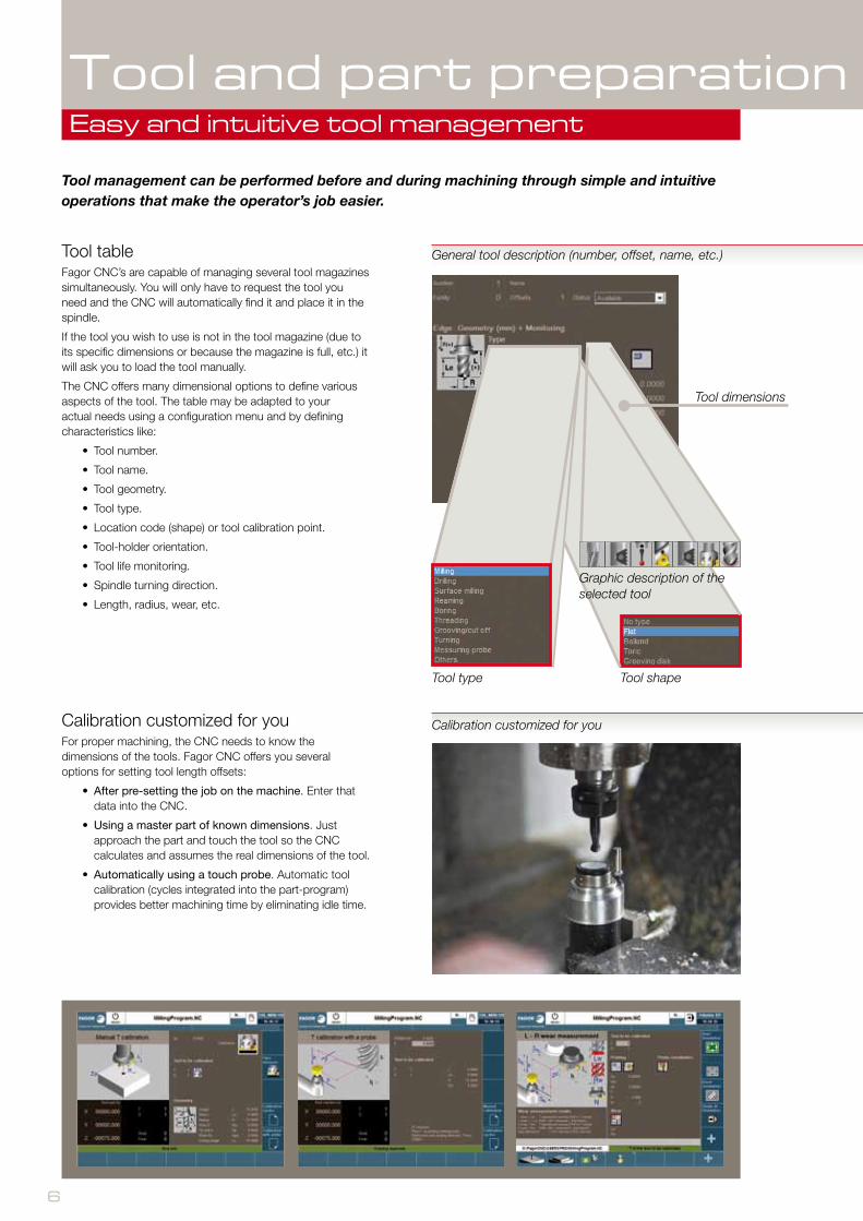
Tool tableFagor CNC’s are capable of managing several tool magazines simultaneously. You will only have to request the tool you need and the CNC will automatically find it and place it in the spindle.
If the tool you wish to use is not in the tool magazine (due to its specific dimensions or because the magazine is full, etc.) it will ask you to load the tool manually.
The CNC offers many dimensional options to define various aspects of the tool. The table may be adapted to your actual needs using a configuration menu and by defining characteristics like:
• Tool number.
• Tool name.
• Tool geometry.
• Tool type.
• Location code (shape) or tool calibration point.
• Tool-holder orientation.
• Tool life monitoring.
• Spindle turning direction.
• Length, radius, wear, etc.
Calibration customized for youFor proper machining, the CNC needs to know the dimensions of the tools. Fagor CNC offers you several options for setting tool length offsets:
• After pre-setting the job on the machine. Enter that data into the CNC.
• Using a master part of known dimensions. Just approach the part and touch the tool so the CNC calculates and assumes the real dimensions of the tool.
• Automatically using a touch probe. Automatic tool calibration (cycles integrated into the part-program) provides better machining time by eliminating idle time.
Tool management can be performed before and during machining through simple and intuitive operations that make the operator’s job easier.
Tool and part preparationEasy and intuitive tool management
Calibration customized for you
General tool description (number, offset, name, etc.)
Tool dimensions
Tool type Tool shape
Graphic description of the selected tool

7
C N C 8 0 6 0C N C 8 0 6 5
Part preparationFagor CNCs offers you measuring cycles that help you detect the exact position of the part on the work table. The CNC provides data like corner position, part center, angle that the part may be rotated(skew), etc.
By utilizing this data, the CNC adapts the work coordinates to the actual position of the part eliminating having to reposition the part.
The CNC measuring cycles may be used as follows:
• Manually guided by the CNC. When not using a part measuring probe on the machine, you only have to touch off the part manually with a tool and validate the contact points.
• Automatically. If the machine uses a probe, all these operations are run automatically and managed by various cycles.
Zero offsetsWith the CNC, you can define several reference points on the machine and save them in the memory to be used later. In subsequent machining operations, you can recover these reference points without having to calculate them again thus, avoiding possible errors.
Tool and part preparationQuick and easy part preparation
In order to ensure consistent part quality in a high production environment, Fagor CNC offers you the necessary tools to prepare the machining operation with quick ease.
Zero offsets
Part preparation

8
High speed machiningOptimizes your machine’s efficiency
High speedPart-programs are very often generated using a CAD-CAM system. Fagor CNC’s optimize the various programmed points by smoothing the tool paths through polynomials (Splines).
This polynomial interpolation provides excellent surface finish at high machining speeds.
The tool paths are executed smoothly, without abrupt accelerations or decelerations. In High speed machining the CNC analyzes in advance the tool path changes programmed in a part. This allows adapting the dynamics of the machine thus avoiding marks (ridges) while machining, smooth corner rounding or jerky /abrupt starts and stops of the machine.
FAGOR’S exclusive HSSA system (High Speed Surface Accuracy) offers you two benefits: On the one hand, it helps to reduce mechanical stress on the machine thus increasing the lifespan of various machine components, and, on the other hand, due to lower vibration, the movements are smoother allowing higher feed rate and less machining error resulting in more accurate parts.
xclusive
9
C N C 8 0 6 0C N C 8 0 6 5
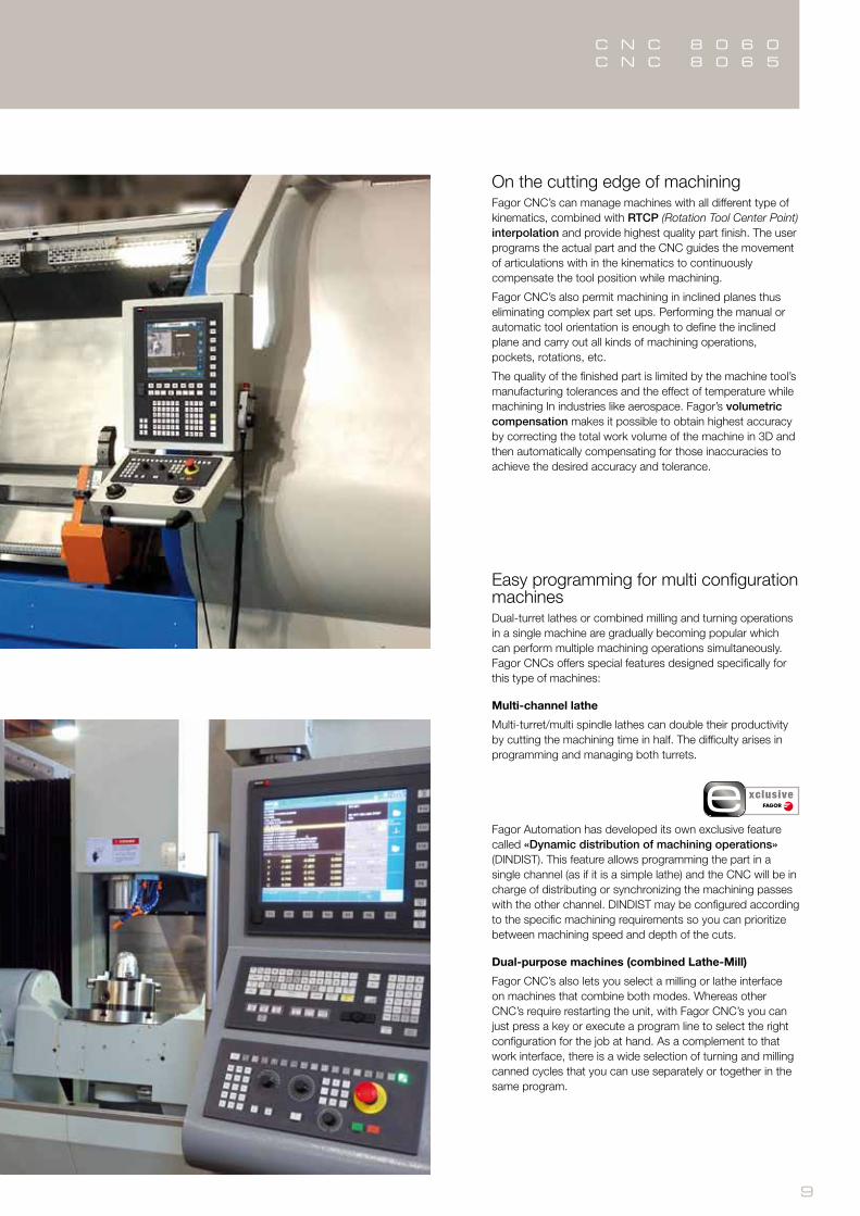
On the cutting edge of machiningFagor CNC’s can manage machines with all different type of kinematics, combined with RTCP (Rotation Tool Center Point) interpolation and provide highest quality part finish. The user programs the actual part and the CNC guides the movement of articulations with in the kinematics to continuously compensate the tool position while machining.
Fagor CNC’s also permit machining in inclined planes thus eliminating complex part set ups. Performing the manual or automatic tool orientation is enough to define the inclined plane and carry out all kinds of machining operations, pockets, rotations, etc.
The quality of the finished part is limited by the machine tool’s manufacturing tolerances and the effect of temperature while machining In industries like aerospace. Fagor’s volumetric compensation makes it possible to obtain highest accuracy by correcting the total work volume of the machine in 3D and then automatically compensating for those inaccuracies to achieve the desired accuracy and tolerance.
Easy programming for multi configuration machinesDual-turret lathes or combined milling and turning operations in a single machine are gradually becoming popular which can perform multiple machining operations simultaneously. Fagor CNCs offers special features designed specifically for this type of machines:
Multi-channel lathe
Multi-turret/multi spindle lathes can double their productivity by cutting the machining time in half. The difficulty arises in programming and managing both turrets.
Fagor Automation has developed its own exclusive feature called «Dynamic distribution of machining operations» (DINDIST). This feature allows programming the part in a single channel (as if it is a simple lathe) and the CNC will be in charge of distributing or synchronizing the machining passes with the other channel. DINDIST may be configured according to the specific machining requirements so you can prioritize between machining speed and depth of the cuts.
Dual-purpose machines (combined Lathe-Mill)
Fagor CNC’s also lets you select a milling or lathe interface on machines that combine both modes. Whereas other CNC’s require restarting the unit, with Fagor CNC’s you can just press a key or execute a program line to select the right configuration for the job at hand. As a complement to that work interface, there is a wide selection of turning and milling canned cycles that you can use separately or together in the same program.
xclusive

10
Long (continuous machining)It resolves unexpected occurrences
Unexpected Machining InterruptionIn long machining operations, if the machine stops unexpectedly due to external causes (a power outage, a machine error, etc.), recovering the unfinished part always poses a big challenge.
With Fagor CNC you can resolve these incidences by resuming the program from where it had stopped, without having to rerun the program from the beginning. It is enough to do an automatic block search to the exact interruption point and resume machining.
Any imperfection caused to the machining surface during unexpected machine stoppage e.g. tool marks etc. can be reworked by simulating the program close to the interruption point and then resuming the operation working through the damaged surface. The user can control the process for resuming the machining operation. The CNC provides the program resuming position and the conditions active at the time of the incident. The user has to bring the tool up to the indicated interruption point and activate the devices (spindle, coolant etc.) in the desired order.
Tool wear during long machining operationsTool life monitoring is a very useful feature in long machining operations or in high production environment. The CNC automatically checks whether the tool has finished its useful life (preset by the user) or not and replaces it with a similar one.
It is also possible to determine the tool condition ( wear or breakage) by monitoring the spindle power consumption. The change to a new tool is managed automatically by the CNC.
This feature avoids the need to interrupt the job or eliminate the need to have an operator in front of the machine at all times. The CNC makes the tool change automatically maintaining the machining conditions and adapting to the dimensions of the new tool as the new tool may not have the same dimensions as the old one.
Unexpected Machining Interruption
Tool wear during long machining operations

11
C N C 8 0 6 0C N C 8 0 6 5
Preventive and verification processWhile machining a part, the CNC allows you to interrupt the execution of a program to check the machining status of the part and take any necessary actions if required.
If the operator detects any imperfections on the part surface during machining, after analyzing it is possible to:
• Change the machining conditions set in the program without having to edit the program.
• Make a tool change if it is worn out or broken.
• Activate non-programmed auxiliary devices like the coolant.
Once the necessary actions have been taken, the execution resumes assuming the changes that the operator has made.
Replacing a damaged or worn-out toolIf you don’t have a tool with identical characteristics to that of the damaged one, you can use another tool with a different length and/or radius and the CNC will adapt to new tool conditions without affecting the programmed path and resume the execution of the part from the interruption point.
Preventive and verification process
xclusive

12
Standard ISO LanguageThis programming level comprises all the functions of standard ISO and it is possible to use the absolute and incremental modes. Fagor CNC’s offer the following functions as standard:
• Tool radius and length compensation.
• Zero offsets, fixture/work offsets, etc.
• Plane coordinate system rotation.
• Mirror image machining.
• Scaling factors.
• Different levels of pocket machining.
• Canned cycles for drilling, threading, center punching, etc.
• Program area repeating cycles.
• Work zones.
• Helical tool paths.
• Collision detection.
Parametric languageIn parametric programming, geometric and technical data may be set through user-defined parameters.
These parameters may be used to store either constant values or variables. Mathematical operations may be carried out to calculate tool paths, repetitions, etc.
For repetitive tasks, Fagor CNC’s let you create your own subroutines or cycles. To create these special cycles, you can combine the parametric language with instructions especially designed for this purpose.
ProGTL3 languageSometimes, the parametric language may not be the most efficient way to program complex shapes and it may take too long.
For such complex parts, Fagor offers the advanced programming language ProGTL3 (Professional Geometric and Technical Language). It is a high-level programming language where you can program the shape of the part assisted by the Profile Editor. While programming, you can view the shape of the geometry being created.
With the ProGTL3 language, you can program elements such as points, straight lines, arcs, corner rounding (radius blend), etc. as well as use geometries that do not belong to the final part, but help create complex shapes.
ProgrammingChoose from four programming methods
xclusive
13
C N C 8 0 6 0C N C 8 0 6 5
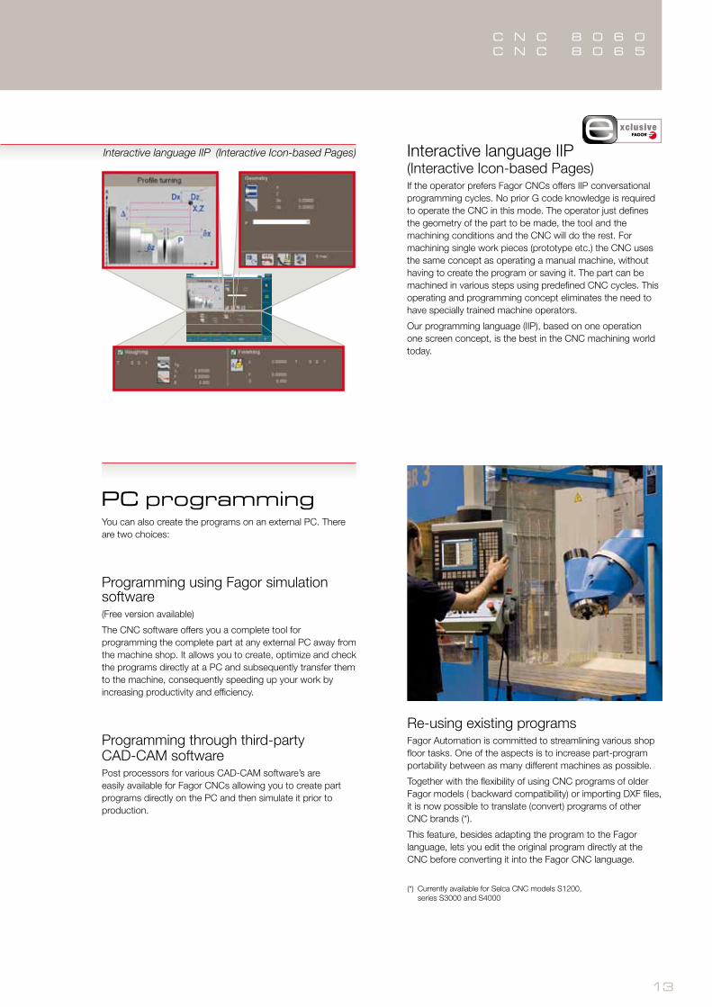
Interactive language IIP (Interactive Icon-based Pages)If the operator prefers Fagor CNCs offers IIP conversational programming cycles. No prior G code knowledge is required to operate the CNC in this mode. The operator just defines the geometry of the part to be made, the tool and the machining conditions and the CNC will do the rest. For machining single work pieces (prototype etc.) the CNC uses the same concept as operating a manual machine, without having to create the program or saving it. The part can be machined in various steps using predefined CNC cycles. This operating and programming concept eliminates the need to have specially trained machine operators.
Our programming language (IIP), based on one operation one screen concept, is the best in the CNC machining world today.
Interactive language IIP (Interactive Icon-based Pages)
PC programmingYou can also create the programs on an external PC. There are two choices:
Programming using Fagor simulation software(Free version available)
The CNC software offers you a complete tool for programming the complete part at any external PC away from the machine shop. It allows you to create, optimize and check the programs directly at a PC and subsequently transfer them to the machine, consequently speeding up your work by increasing productivity and efficiency.
Programming through third-party CAD-CAM softwarePost processors for various CAD-CAM software’s are easily available for Fagor CNCs allowing you to create part programs directly on the PC and then simulate it prior to production.
Re-using existing programsFagor Automation is committed to streamlining various shop floor tasks. One of the aspects is to increase part-program portability between as many different machines as possible.
Together with the flexibility of using CNC programs of older Fagor models ( backward compatibility) or importing DXF files, it is now possible to translate (convert) programs of other CNC brands (*).
This feature, besides adapting the program to the Fagor language, lets you edit the original program directly at the CNC before converting it into the Fagor CNC language.
(*) Currently available for Selca CNC models S1200, series S3000 and S4000
xclusive

4
1
3
2 8
9
5 6
7
10
C N C 8 0 6 0C N C 8 0 6 5
15 (1) 15 (2)14
Cycle examples, from simple to the most complex
3D profile pocket with inside islands
Cycle Section profile first islandPlane profile with two islands Section profile second islandSection profile outside profile Final part
3D profile pocket without inside islands
Cycle Plane profile without islands Section profile Final part
2D profile pocket with inside islands
Milling of point-to-point profile Milling of a free profile
Plane profile with two islandsPlane profile without islands Final partFinal part
2D profile pocket without inside islands
CycleCycle
Profile programmed in ProGTL3 or Fagor language
Final partFinal part CycleCycle
Milling
Milling with parallel passes
Plane milling (Surface milling)
Helical millingCycle
Final part
Rectangular boss
Cycle
Rectangular pocket with rounding along a line
Final partCycle
Final part
Thread milling (or drilling cycle) on a rectangle
Cycle

2
1
3
4
5
6
7
8
9
17 (1) 17 (2)16
11
13
10
12
14
15
C N C 8 0 6 0C N C 8 0 6 5
OTHER WORK CYCLES WITH C/Y AXES
Turning Cycle examples, from simple to the most complex
Turning and vertex rounding ZC plane profile
2D profiled pocket in the ZC or YZ plane
Circular or rectangular pocket in the XC or XY plane
Multiple longitudinal or face slot milling
Simple face grooving with multiple repetitions
Profile in the XC plane
Rectangular or circular pocket in ZC or YZ
Multiple drilling or threading cycles with C axis
Final part Final part
Final part Final part
Cycle Cycle
Cycle Cycle
Final partPart profileFinal partCycle Cycle
Part profileFinal part Final partCycle Cycle
Point-to-point turning
Outside profile turning
Inside profile turningLongitudinal inclined grooving
Vertex rounding
Taper or cylindrical threading


18
CNC 8060 CNC 8065CNC 8065
POWER
Main characteristicsMonitor 10.4” 10.4”/15” 10.4”/15”
User memory Minimum 0.5 GB 300 MB to 14.3 GB 2.3 to 14.3 GB
Ethernet O O O
USB O O O
Mouse integrated into the keyboard x ∆ ∆
Touch screen ∆ ∆ ∆
Nanometric accuracy O O O
Tele-Diagnosis O O O
File encryption O O O
Machine configurationMaximum number of axes 6 8 28
Maximum number of spindles 3 1/2 4
Maximum interpolated axes 4 8 28
Gantry O O O
Tandem ∆ ∆ O
Kinematics O O O
Work in inclined planes O O O
RTCP x ∆ ∆
Volumetric compensation x x ∆
Dynamic machining distribution (DINDIST) x ∆ ∆
Dual-purpose (lathe-mill) machine features x x ∆
Spindle synchronization ∆ ∆ ∆
ToolsTool offset 100000 100000 100000
Tool life monitoring O O O
Tool geometry compensation O O O
Tool measuring cycles O O O
Display & SimulationClock & parts counter O O O
Machining time estimate O O O
Simulation in selected planes O O O
3D simulation O O O
HD Graphic simulation ∆ ∆ ∆
Zoom in simulation O O O
CNC simulation software for PC O O O
O Default
∆ Optional
x Not available
Technical characteristics

19
C N C 8 0 6 0C N C 8 0 6 5
CNC 8060 CNC 8065CNC 8065
POWER
Editing & ProgrammingISO and parametric language O O O
Probing canned cycles ∆ ∆ O
IIP (Interactive Icon-based Pages) programming language ∆ ∆ O
ProGTL3 language ∆ ∆ O
CNC language translator ∆ ∆ O
Zero offsets 99 x 10 fixtures (clamps) 99 x 10 fixtures (clamps) 99 x 10 fixtures (clamps)
Incremental zero offsets 99 99 99
Master-slave axis Hand wheel movement O O O
Teach-in editing O O O
DXF converter O O O
Profile editor (Mini CAD) O O O
Programming features (Mill ing)Tapping / rigid tapping O O OHelical interpolation O O O
Wide selection of drilling cycles O O O
Threading, boring and reaming cycles O O O
Rectangular and circular pocket cycles O O O
Bore milling cycle O O O
Thread milling cycles O O O
2D pockets for user-defined shapes O O O
3D pockets with islands for user-defined shapes O O O
Programming features (Lathe)Many turning cycles O O OMany facing cycles O O O
Wide selection of drilling and threading cycles O O O
Constant-pitch and variable-pitch threading O O O
Wide selection of threading cycles O O O
Many grooving cycles O O O
Profile cycle along the X axis O O O
Profile cycle along the Z axis O O O
Pocket cycles in the XC, ZC planes O O O
Pocket cycles in the XY, YZ planes O O O
Multiple pocket cycles O O O
2D pockets for user-defined shapes O O O
O Default
∆ Optional
x Not available

ER-073/1994
Fagor Automation, S. Coop.Bº San Andrés, 19E-20500 Arrasate - MondragónSPAINTel.: +34 943 719 200Fax.: +34 943 791 712E-mail: [email protected]
www.fagorautomat ion.com
worldwide automation
AALBORG
BARCELONA
BUCHAREST
BUDAPEST
CLERMONT FERRAND
GOMEL
GÖPPINGEN
GÖTEBORG
HËLSINKI
ISTANBUL
IZEGEM
KAPELLEN
LOG PRI BREZOVICI
MILANO
MOSKVA
NEUCHATEL
NORTHAMPTON
PORTO
PRAHA
ROOSENDAAL
THESSALONIKI
UTRECHT
WIEN
WROCLAW
USURBILESKORIATZABEIJING
MONDRAGÓN
BANGALORE
BANGKOK
CHENGDU
GUANGZHOU
HO CHI MINH CITY
HONG KONG
ISLAMABAD
JAKARTA
KUALA LUMPUR
MANILA
NANJING
NEW DELHI
PUNE
RAJKOT
SHANGHAI
SEOUL
SINGAPORE
TAICHUNG
TEL-AVIV
AUCKLAND
DUNEDIN
MELBOURNE
SYDNEY
BOGOTÁ
BUENOS AIRES
CHICAGO
EL SALVADOR D.F.
HOUSTON
LIMA
LOS ANGELES
MEXICO D.F.
MONTEVIDEO
MONTREAL
NEW JERSEY
NUEVO LEÓN
SANTIAGO
SAO PAULO
TAMPA
TORONTO
JOHANNESBURG
FAGOR AUTOMATION shall not be held responsible for any printing or transcribing errors in this catalogand reserves the right to make any changes to the characteristics of its products without prior notice.
europe
americaHeadquartersPlants
africa
asia
oceania
CN
C 8
060
8065
U
SE
R E
N 0
413
Fagor Automation holds the ISO 9001 Quality System Certificate and the
Certificate for all products manufactured.
subsidiary d is t r ibu to r