
CMP TECHNICAL GUIDE
24
CMP TECHNICAL GUIDE A guide to using corrugated metal pipe
Transcript of CMP TECHNICAL GUIDE

CMP TECHNICAL GUIDEA guide to using corrugated metal pipe

1
CMP TECHNICAL GUIDEA GUIDE TO USING CORRUGATED METAL PIPECorrugated Steel Pipe (CSP)Corrugated Aluminum Alloy Pipe (CAAP)
SPECIFICATION GUIDE 2-5
INSTALLATION GUIDE 6-8
SERVICE LIFE GUIDE 9
COVER HEIGHT TABLES 10-14
AISI CSP 10
AASHTO CSP 11
AASHTO CAAP 12
AISI CSP-ARCH 13
AASHTO CSP-ARCH AND CAAP-ARCH 14
PIPE-ARCH DESIGN SUPPLEMENTAL 15
PIPE-ARCH LAYOUTS 16
MANNING’S EQUATION VARIABLES 17
END TREATMENT 18-19
HANDLING WEIGHTS 20
ENGINEER NOTES 21-22

SPECIFICATION GUIDE OVERVIEWSpecifying CMP products involves some familiarity with the industry publications, and this Specification Guide serves as a locus of these standards. In general, the design engineer will need to:
1. Select an appropriate CMP material type, manufacturing standard, and joint performance (pages 2-4).2. Ensure the CMP material meets a structural design standard in relation to burial depths and live loads (page 5).3. Incorporate a corresponding installation standard into the project documents (page 5).
Selecting the Appropriate Pipe Material Type and Standard Specifying CMP products first involves an understanding of the application. Typical applications such as road culverts and storm drains will involve size and shape determinations for hydraulic capacity. Other applications may involve perforated CMP for various subsurface drainage purposes. Secondary considerations may be towards CMP material types to meet any durability or service life requirements. Subsequent decisions to economize the product are based on strength demands so that the lightest gauge or metal thickness is selected.
There are three primary ASTM CMP standards (AASHTO equivalents in parenthesis). One for metallic coated steel pipe, another for polymer coated steel pipe, and a third for aluminum alloy pipe. Each standard uses the same classification system to identify the pipe type, and each standard makes provisions for the different corrugations and metal thicknesses available.
STEP 1, Select Pipe Type. This primarily involves selecting either a round or pipe-arch shape, and secondarily whether a standard corrugation (sinusoidal arc-and-tangent) or smooth interior is needed for the application. Pipe-Arch shapes are for low cover conditions that require more hydraulic capacity than round pipe can deliver at the same invert elevation (figure 7, page 17). Opting for a round shape when possible will provide greater economy for the project. Round pipes used for underdrains or for underground disposal of water will require the additional step of selecting either a Class1 or Class 2 perforation pattern.
STEP 1. PIPE CLASSIFICATION Corrugation Description Steel Aluminum
Type I Round Pipe, Exterior/Interior Corrugations 1½ x ¼ in. Sinusoidal 6-10 in.
Type IR Round Pipe, Smooth Interior (Spiral Rib Pipe) 22/3 x ½ in. Sinusoidal 12-72 in. 12-72 in.
Type II Type I Pipe Reformed into a Pipe-Arch 3 x 1 in. Sinusoidal 48-102 in. 36-120 in.
Type IIR Type IR Pipe Reformed into a Pipe-Arch 5 x 1 in. Sinusoidal 48-144 in.
Type III Type I Pipe with Class 1 or Class 2 Perforations ¾ x ¾ x 7½ in. Spiral Rib 15-102 in. 15-84 in.
Perforated Pipe. Most applications require non-perforated pipe. Where applications for perforated pipe are necessary there are two perforation patterns available, Class 1 and Class 2, and the CMP standards use parallel classification systems for each. Inherent in the classification systems are the size, spacing and placement of the perforations.
Class 1, Partially Perforated Pipe (Subsurface Drainage). Class 1 perforations are for pipe intended to be used for subsurface drainage, where the pipe maintains an unperforated segment above the invert for a flow channel. Perforations have nominal diameters of ⅜-in arranged in rows parallel to the axis of the pipe with one perforation in each row for each corrugation. Rows of perforations are arranged in two equal groups placed symmetrically on each side of the lower unperforated segment corresponding to the flow line of the pipe.
Table 1. Class 1 Perforation Rows Table 2. Class 1 Perforation Inlet Area
D (in.)
Total Rows
Hmax (in.)
Lmin. (in.)
Corrugation Inlet Area
6 4 2.8 3.8 1½ x ¼ in. 3.53 in2/ft (6,8,10 in)
8 4 3.7 5.1 22/3 x ½ in. 2.98 in²/ft (12-21 in)
10 4 4.6 6.4 22/3 x ½ in. 3.98 in²/ft (≥24 in)
12 6 5.5 7.7 3 x 1 in. 3.53 in²/ft (all diameters)
15 6 8.9 9.6 5 x 1 in. 2.12 in²/ft (all diameters)
18 6 8.3 11.5Inlet areas based on a nominal 3/8-in. diameter perforation.21 6 9.7 13.4
>– 24 8 0.46D 0.64D
Class 2, Fully Perforated Pipe (Subsurface Disposal). Class 2 perforations are for pipe intended to be used for subsurface disposal of water. Perforations around the entire periphery of the pipe allows both infiltration and complete exfiltration (i.e. disposal into the ground). The common use of Class 2 perforations is for pipe used in groundwater recharge systems. Class 2 perforations provide a minimum inlet area of 3.3 in²/ft². Thirty 3/8-in diameter perforations per square foot of surface satisfies this requirement.
SPECIFICATION GUIDE
CL
CL
H
80o Minimum
L
85o M
axim
um
Figure 1. Class 1 Perforations

STEP 2, Select Pipe Material. This step presumes a service life is defined for the project so that the most economical decision can be made and the proper pipe standard specified. See page 9 for a review of anticipated service life along with the references cited there for a more in-depth treatment.
STEP 2. PIPE STANDARD See page 9 for Service Life Assignments
ASTM A760 (AASHTO M36) Galvanized or Aluminized Steel Pipe Galvanized Coil Coating weight 2 oz/sf of coil
ASTM A762 (AASHTO M245) Polymer-Coated Steel Pipe Aluminized Coil Coating weight 1 oz/sf of coil
ASTM B745 (AASHTO M196) Aluminum Alloy Pipe Polymer Coil Laminate thickness 10 mil each side
STEP 3, Select Lightest Gauge. Industry guidelines have established empirical flexibility limits that a gauge-span combination should have to be safely handled and installed. While these limits are quantified by a standard computation called the Flexibility Factor (FF), in the final analysis the limits represent a subjective approach in defining when a structure may not be rigid enough to withstand compaction forces alongside the pipe. When the FF is slightly exceeded the designer should specify a more readily compacted embedment material such as crushed stone. Beyond that, the gauge will generally increase with higher fill heights to meet strength requirements as illustrated on the cover height tables located on pages 10-14.
Explanatory notes provide additional clarification to the various cover height tables and can also be correlated to the structural design standards listed on page 5. It should be noted that gauge considerations for the pipe-arch shapes are not always governed by flexibility limits since some of the corrugation patterns require a heavier gauge to properly form the arch shape, and sharp corner radii provide for an entirely different design consideration (see the Pipe-Arch Design Supplemental, page 15).
STEP 3. PIPE GAUGE See pages 10-14 for Cover Height Tables
Gauge Steel Aluminum Gauge Steel Aluminum
18 GA 0.052 in. 12 GA 0.109 in. 0.105 in.
16 GA 0.064 in. 0.060 in. 10 GA 0.138 in. 0.135 in.
14 GA 0.079 in. 0.075 in. 8 GA 0.168 in. 0.164 in.
STEP 4, Select Joint Performance. Each of the above-mentioned CMP standards also provides corresponding joint performance criteria based upon the ability of the joining system to control leakage or material infiltration.
Soil Tight – (default criteria) resists infiltration of soil particles larger than those passing a No. 200 Sieve
Silt Tight – resists infiltration of soil particles equivalent to an apparent opening size (AOS) of 70
Leak Resistant - leakage limited to 200 gal/in-dia/mile/day at a defined pressure head from 0-25ft
Special Design - zero leakage for 10 min at a defined pressure head from 10-25ft in a laboratory setting
Pipe joining systems defined in the CMP standards include several wrap-around styles of metal bands (see figure 2 above) of the same material as the pipes being joined, albeit in a lighter gauge. The different types of coupling bands and connecting hardware are shown on the following page. The tables below show minimum width and thickness requirements identified in the CMP standards.
MIN BAND GAUGE MIN BAND WIDTH (CSP) MIN BAND WIDTH (CAAP) Pipe Band Dia. Band Corrugation Dia. Annular Dimple
18-12 GA 18 GA 12-36 in. 7 in. 22/3 x ½ in. 12-36 in. 7 in. 10½ in. 10 GA 16 GA 42-144 in. 10½ in. 42-72 in. 10½ in. 10½ in. 8 GA 14 GA 78-120 in. 10½ in. 16¼ in.
For pipe with annular corrugated ends
3 x 1 in. 30-72 in. 12 in. 10½ in.
78-120 in. 12 in. 16¼ in.
Specifying Joint Performance. In general, all styles of metal bands will provide soil-tight performance but will need additional materials to meet higher demands. Silt-tight performance will require, at a minimum, a geotextile wrap around the banded joint. The various leak resistant or special design performances will require the addition of a gasket that meets the material requirements of ASTM D1056 (see following page).__________________________________________________________________________________________________________________
For additional information on specifying joint performance see below standard, which provides definitions of joint performance terms, a rational design methodology for appropriate joint performance requirements, and uniform criteria for manufacturers' joint qualifications.
AASHTO R82, Standard Practice for Pipe Joint Selection for Highway Culvert and Storm Drains
SPECIFICATION GUIDE
Lane Enterprises, Inc. | 3905 Hartzdale Drive, Suite 514 | Camp Hill, PA 17011 | P: 717.761.8175 | F: 717.761.5055 | lane-enterprises.com
3
Figure 2. Wrap-around metal band.

COUPLING BANDSPipe corrugations are helically formed but the CMP standards make provisions for the pipe ends to be reformed into annular corrugations to allow a continuous index or seal to be made around the entire periphery of the pipe end, and to better engage certain coupling bands.
All annular corrugated ends are reformed with a 22/3 x ½-in corrugation by a process commonly known as rerolling.
Corrugated Bands* Annular corrugated bands are available in nominal widths of 7, 12 and 24-in.
Partially Corrugated Bands* Flat bands with one annular corrugation along each edge are available in nominal widths of 7 and 12-in.
Flat Bands* Bands with no corrugations or projections are available in nominal widths of 7, 12 and 24-in.
Dimple Bands Bands with dimple projections in annular rows. Along with flat bands they may be used on pipe with helical or annular corrugations. Dimple bands are available for 12 through 54-in CMP.
Sleeve Gaskets A 3/8-in thick neoprene material that slides over the pipe ends and underlays the connecting band to enhance the leak resistance quality of the joint. Sleeve gaskets are available in 7, 12, and 24-in widths. See figure 3 above.
NOTE: *Polymer coated bands shown for contrast.
CONNECTING BAND HARDWAREStandard Lug Connector* Assembly typically uses the dual lug configuration (left). The multiple lug configuration (right) is for 24-in wide bands.
Angle Connection* Assembly uses the two-bolt configuration for 7-in bands (left), a three-bolt configuration for 12-in bands (middle), and a six-bolt configuration for 24-in bands (right).
Bar and Strap Connector* Assembly typically consists of the single-strap configuration (left). The multi-strap configuration (right) can be used for 12-in wide bands when specified.
Rod and Lug (½-in Ø SILO ROD & LUG) Assembly typically consists of the dual rod configuration (left) and may be used on corrugated or partially corrugated bands. The multiple rod configuration (right) is used for 24-in corrugated bands only.
SPECIFICATION GUIDE
Figure 3. Sleeve Gaskets.
Multiple
ContinuousMultiple
Continuous

SELECTING THE APPROPRIATE STRUCTURAL STANDARDCMP Structural Design Standards
Standard methods of structural analysis are generally based on research adopted by AASHTO. Standards with slight variations have also been adopted by ASTM. The railway industry, represented by AREMA, maintains distinct material and design standards to ensure railway live loading (E80) and its effects are appropriately managed.
The cover height tables on pages 10 and 13 show results generated by the AISI method, an Allowable Stress Design method for corrugated steel pipe that’s fully outlined in the first three general industry references below.
Note that cover height tables were not prepared for railway applications since these tables are included in the AREMA Manual for Railway Engineering publication cited below for both steel and aluminum round and pipe-arch shapes.
The following standards are listed with the qualifying remark that the AASHTO method is the primary design standard outside railway applications:
ASTM A796 Practice for Structural Design of Corrugated Steel Pipe, Pipe-Arches, and Arches for Storm and Sanitary Sewers and Other Buried Applications
ASTM B790 Practice for Structural Design of Corrugated Aluminum Pipe, Pipe-Arches, and Arches for Culverts, Storm Sewers, and Other Buried Conduits
ASTM A998 Practice for Structural Design of Reinforcements for Fittings in Factory–Made Corrugated Steel Pipe for Sewers and Other Applications
AREMA 2020 Manual for Railway Engineering, Section 4.13, Design Criteria for Corrugated Metal Pipes
AASHTO LRFD Bridge Design Specifications, Section 3, Loads and Load Factors [9th Edition]
AASHTO LRFD Bridge Design Specifications, Section 12, Buried Structures and Tunnel Liners [9th Edition]
For an important resource visit www.candeforculverts.com. CANDE is a free special purpose, 2D finite element computer program developed for the structural design and analysis of soil bridges, buried culverts and underground structures. See especially its Solution Methods and Formulations for a thorough understanding of CMP behavior and modelling considerations
SELECTING THE APPROPRIATE INSTALLATION STANDARDCMP Installation Standards
Corrugated metal pipe (CMP) is a flexible pipe material that derives structural support from the strength and stiffness of the backfill envelope. The backfill-culvert interaction system defines the ability of CMP to withstand service loads. Installation specifications illustrating backfill envelopes, addressing appropriate backfill material selection, and identifying proper compaction guidelines help ensure acceptable levels of backfill-culvert interaction are realized:
ASTM A798 Practice for Installing Factory-Made Corrugated Steel Pipe for Sewers
ASTM B788 Practice for Installing Factory-Made Corrugated Aluminum Culverts and Storm Sewer Pipe
AASHTO LRFD Bridge Construction Specifications, Section 26, Metal Culverts
AREMA Manual for Railway Engineering, Section 4.12, Assembly and Installation of Pipe Culverts
See especially the National Corrugated Steel Pipe Association Installation Manual at NCSPA.org For a highly recommended general resource see Pipeline Installation 2.0 by Amster Howard [2nd Edition 2015]
GENERAL INDUSTRY REFERENCESCorrugated Steel Pipe Design Manual by the National Corrugated Steel Pipe Association (NCSPA) [2nd Edition 2018] Handbook of Steel Drainage & Highway Construction Products by the American Iron and Steel Institute (AISI) [1994 Edition] Modern Sewer Design by the NCSPA and the AISI [4th Edition, 1999]
2020 AREMA Manual for Railway Engineering, Chapter 1, Part 4 Culverts
SPECIFICATION GUIDE
Lane Enterprises, Inc. | 3905 Hartzdale Drive, Suite 514 | Camp Hill, PA 17011 | P: 717.761.8175 | F: 717.761.5055 | lane-enterprises.com
5

GENERAL OVERVIEWPipe should be unloaded and handled with reasonable care to avoid any undue damage, especially to the coatings. Using two equally spaced lift points for the larger sizes will prevent the pipe ends from striking objects or being dragged along the ground.
Pipe installation generally progresses in an upstream fashion beginning at the outlet of the drainage improvement to be constructed and should be uniformly supported on grade throughout the alignment.
Joint gaps for circular pipe up to one inch can be expected. A joint gap for circular pipe between one and two inches is not a cause for any undue concern but should be investigated to determine if any corrective actions are necessary. Greater joint gaps may be encountered with the arch shapes in the larger sizes due to the manufacturing process. Specifying a 2-ft wide connecting band with an underlying gasket typically offsets any joint gap issues. Where leakage is not a concern the gasket requirement may be mitigated by the inclusion of a non-woven geotextile wrap around the joint exterior.
The foundation of a pipe installation is ideally the undisturbed native material resulting from a carefully graded excavation. Replacing soft or unyielding material with additional bedding will help ensure uniform pipe support. ASTM A798 notes that unsuitable foundation materials are replaced across the width of the trench to a depth of one-half inch per foot of design fill over the pipe with a 24-inch maximum.
Note: materials used for foundation improvements (and all backfill materials) must have gradations compatible with adjacent soils to avoid migration or be separated with a non-woven geotextile.
Pipe bedding is constructed in a manner to provide uniform pipe support to the design line and grade, with the middle-third beneath round pipe left loose to cradle the pipe so that the load is better distributed along the bottom segment of the pipe.
For pipe-arch shapes, however, a shaped bedding width corresponding to the flat bottom arc will be needed to eliminate the challenge of filling this area after-the-fact. The shaped bedding width must not exceed this width as select, compacted material is needed beneath the sharp corners for structural support.
A minimum bedding thickness of two times the corrugation depth is generally recommended. The bedding material is typically the same material used for pipe embedment, ideally a clean, cohesionless, free-draining soil with particles that move around easily in order to conform to the shape of the pipe bottom.
Pipe haunching is carried out on both sides simultaneously to avoid rolling the pipe. Gently dumping small amounts of material on top of the pipe will provide some stability while material falling beside the pipe can be pushed into the haunch zone. Filling adjacent sidefill zones will provide lateral support to the haunch material during the process. Loose layers in four to six-inch lifts will permit the backfill material to be worked into the haunch zone.
Material should be manually placed in the haunches. Techniques such as rodding, knifing, or shovel slicing are effective to ensure the haunch is filled. Mechanical tampers, manual tampers, or other means that fill voids and meet specified compaction levels must be used carefully. Controlling the compaction force will prevent the pipe from lifting off grade. Do not permit compaction equipment to contact the pipe.
Pipe embedment is constructed by placing select materials equally on each side of the pipe in loose layers of 6 to 12 inches. Each layer is then compacted before adding the next lift. Lift construction progressing equally along each side of the pipe is necessary for pipe support. For convenience, lift construction may alternate from side to side such that the differential is never more than one lift. Pipe embedment is generally concluded when select fill is extended to the minimum cover height.
Bedding and Embedment MaterialsBedding and structural backfill is commonly a well-graded granular material free of organics, rock fragments larger than three inches, chunks of highly plastic clay, frozen lumps, and corrosive or otherwise deleterious materials. Gravel-sand mixtures are ideal.
Poorly graded clean crushed rock with 100% passing the 1½-in sieve provides excellent pipe support and is ideal when compactive forces need to be lessened to the extent possible for highly flexible conduits.
Processed aggregates with angular interlocking particles provide the best support with a minimum of compaction effort over a wide range of moisture content and lift depth. Uniform-graded materials are typically angular rock fragments with a nominal size distribution from ¾ to 1½-in.
INSTALLATION GUIDE
Bedding blanket of loose, fine graded granular material shaped to the bottom arc.
Corner support using compacted structural backfill.

Trench InstallationPipe installations in cut trenches can begin once the bedding has been properly constructed over a suitable foundation. Trench sidewalls must be stable, supported, or laid back according to OSHA regulations. Narrower trench widths normally provide better pipe support if the native soils forming the trench wall are stable, but the width must be sufficient for proper haunching, side fill compaction, and safe working conditions.
Pipe should be placed on bedding shaped to the pipe invert for a width of one-half the diameter or span where the distance between the pipe and trench wall is less than 2-ft.
Trench Width. As a guide, AASHTO indicates the minimum trench width should not be less than the greater of the pipe diameter plus 16 inches or the pipe diameter times 1.5 plus 12 inches.
Structural Backfill. Select materials are specified for use in the structural backfill or embedment zone, consisting of a bedding layer beneath the pipe, the critical haunch zones beneath the pipe sides and the bedding layer, the side zones, and a distance above the pipe equivalent to the minimum cover (see below).
Minimum Bedding Thickness. Loosely placed to a depth of at least two-times the corrugation depth.
Minimum Cover. A distance above the pipe equivalent to the greater of one-eighth the pipe span or 12 inches.
Regular Backfill. Depends on final use of surface and is per project plans and specifications.
Trench Box Installation The use of a trench box for the deeper installations typically challenges the ability to maintain side fill support as the trench box is advanced.
Voids left by the trench box walls, as well as the void left between the trench box and the excavation must be addressed to ensure compacted support extends to the undisturbed native materials. Any sloughed material against the outside of the trench box must also be addressed.
Trench width requirements correspond to the distance between the interior walls of the trench box and therefore the excavation width will increase accordingly.
Do not compact embedment material against the walls of the trench box so as not to disturb the installed pipe and its embedment when moving the trench box.
Proper placement and compaction of the side fill is done below the bottom edge of the trench box as it is raised vertically in approximate 12 inch increments, removing any sloughed material as the process continues.
The practice of using a sub-trench will mitigate the challenges associated with haunch and side fill placement and compaction.
Where sub-trenches are not allowed the trench box should be widened to mitigate the challenges.
Using manufactured aggregates that require little compactive effort will produce the best results for trench box installations.
INSTALLATION GUIDE
Excavated TrenchWidth
Str
uctu
ral
Bac
kfill
Reg
ular
Bac
kfill
24” Max.Sub-Trench
Minimum Trench Width
Bedding
Lane Enterprises, Inc. | 3905 Hartzdale Drive, Suite 514 | Camp Hill, PA 17011 | P: 717.761.8175 | F: 717.761.5055 | lane-enterprises.com
7

Embankment InstallationEmbankments may be constructed in lifts with the pipe in place or constructed to a height corresponding to the pipe springline before excavating a trench for installing the pipe. In any case a minimum width of structural envelope is needed for lateral restraint.
As a guide, AASHTO indicates the minimum width of structural envelope on each side of the pipe should not be less than one span for diameters (or spans) less than 24 inches, 2-ft for spans between 24 and 144 inches, and 5-ft for spans exceeding 144 inches.
Also, the combined width of the structural envelope and the embankment beyond the envelope must be adequate to support all the loads on the pipe. A good practice is to provide a total combined width of two pipe spans on each side of the pipe.
Lift Construction Above The PipeFor lift construction to the minimum cover height only walk-behind compaction equipment shall be used. Once minimum cover has been established small dozers may be used to track back and forth with no twisting/turning. Tracked excavators and smooth drum vibratory soil compactors may be used once 24 inches have been established above the pipe.
Multiple Pipe RunsInstallation methods for multiple runs of pipe shall be consistent with trench and embankment installations with the added condition that backfilling progress evenly across all pipe runs. Spacing between pipes shall be sufficient to permit the proper placement and compaction of structural backfill in the haunch and between the structures. As a guide, AASHTO indicates the minimum spacing between pipes should not be less than that shown in the tables below:
PIPE DIAMETER MINIMUM SPACING
Up to 24 in. 12 in.
24-72 in. ½D
Greater than 72 in. 36 in.
PIPE-ARCH SPAN MINIMUM SPACING
Up to 36 in. 12 in.
36-108 in. S/3
Greater than 108 in. 36 in.
Temporary Construction CoverAs an added measure of protection during the construction process additional (temporary) compacted cover may be needed over the pipe due to the high frequency of traffic and the potential for rutting associated with large tread rubber tires. The following table provides industry guidelines based on axle weights:
MINIMUM TEMPORARY COVER FOR CONSTRUCTION LOADS (FT)
Span (in.)
Axle Loads (KIPS)
18-50 50-75 75-110 110-150
12 to 42 2.0 2.5 3.0 3.0
48 to 72 3.0 3.0 3.5 4.0
78 to 120 3.0 3.5 4.0 4.0
126 to 144 3.5 4.0 4.5 4.5
Designations for Bedding and BackfillSoils meeting the requirements of Soil Groups GW, GP, GM, GC, SW and SP as defined in ASTM D2487 are generally acceptable when properly compacted. Soil Groups SM and SC are acceptable but will require closer control to obtain the specified density. AASHTO M145 groups A-1, A-2 or A-3 are minimum AASHTO requirements. Commonly used AASHTO designations for crushed rock are AASHTO Nos. 57, 67 and 8.
ASTM D2487 AASHTO M145 DESCRIPTION
GW GP SP A-1-a Well-graded gravel
GM SM SP A-1-b Gravelly sand
GM SM ML SP GP A-2-4 Sand and gravel with low plasticity silt
SC GC GM A-2-5 Sand and gravels with elastic silt
SC GC A-2-6 Sands with clay fines
SC GC A-2-7 Sands with highly plastic clay fines
SW SP SM A-3 Fine sands, such as beach sand
The above table shows a descending order of backfill quality where non-plastic sands and gravels are preferred, especially for the larger, more flexible pipe, higher fills, and trench box installations. Compaction to 90% SPD is generally sufficient for all cases.
Filter FabricThe migration of fines into the pipe embedment can result in loss of pipe support. The gradation and relative size of the embedment and adjacent materials must be compatible to minimize this migration. When coarse and open-graded material is placed adjacent to a finer material a filter fabric (or other acceptable means) should be used.
INSTALLATION GUIDE
2 X Span2 X Span
Minimum Constructed Embankment
Minimum Structural Envelope
Span

Corrugated Steel Pipe (CSP) has been in use since the early 20th century, much of this time available with only a galvanized coating. With the addition of several coating options CSP has increased its value and usefulness in providing extended service life over a broader range of environmental conditions.
Environmental conditions can vary considerably from site to site but there are only several variables used to predict service life. The pipe interior (water-side durability) is impacted by effluent abrasion, pH and resistivity, and is typically the controlling factor in service life assignments. The pipe exterior (soil-side durability) is affected by soil pH and resistivity, and is generally not the limiting factor in estimating CSP service life.
Abrasion is a function of the bed load carried by the effluent and its velocity. Abrasion levels are correlated to the classification system developed by the Federal Highway Administration (FHWA).
FHWA ABRASION BED LOAD VELOCITY
Level 1 None None
Level 2 Low Sand/gravel < 5 fps
Level 3 Moderate Sand/gravel 5-15 fps
Level 4 Severe Heavy gravel/rock >15 fps
The pH ranges between 0 and 14 and is a measurement of acidity (pH < 7.0) or alkalinity (pH > 7.0). Resistivity, R [ohm-cm] is a measure of how strongly a material opposes the flow of electric current. A low resistivity indicates a material that readily allows the movement of electric charge and results in greater corrosion rates.
Normal environmental conditions have a pH range between 5.8 and 8.0 with a resistivity greater than 2000 ohm-cm. Mildly corrosive environments have a pH range from 5.0 to 5.8 and a resistivity between 1500 and 2000 ohm-cm. Corrosive environments are characterized by pH’s less than 5.0 and resistivities below 1500 ohm-cm.
Galvanized CSP provides a zinc coating weight of two ounces per square foot of surface area. Galvanized CSP has been in use longer than any other material and much has been learned about the service life of this material. A field investigation conducted in the 1960’s evaluated the service life of roughly 7,000 culverts in terms of pH and resistivity alone, and was subsequently quantified in the following service life equations:
For pH ≤ 7.3 Service Life (Years) = 35.85[Log10 R - Log10 (2160 – 2490 Log10 pH)]
For pH > 7.3 Service Life (Years) = 3.82R0.41
The equations relate the service life for 16 gauge CSP based on a 25% loss of steel in the pipe invert. Longer service life may be achieved with the heavier gauges. For gauges 14, 12, 10 and 8, apply factors 1.3, 1.8, 2.3 and 2.8, respectively.
For pH’s ≤ 7.3 the equation should be applied to both the water- side and soil-side of the pipe. When pH > 7.3 the soil-side is the controlling factor.
An important factor later discovered to have a significant impact on the service life of galvanized coated CSP is the presence of soft water (CaCO3 < 50 ppm). Hard water has an excess of this dissolved salt which is deposited on the pipe in the form of a scale that protects the underlying coating. Had the impact of soft water been recognized at the time of installation the resultant equations would have predicted significantly longer service life for galvanized CSP installed within the environmental guidelines
of today. Aluminized CSP will not be adversely affected by the presence of soft water and therefore is the recommended substitute to galvanized CSP in soft water applications
Aluminized CSP, also referred to as Aluminized Type 2 (ALT2), has a pure aluminum coating of one ounce per square foot of surface area. The aluminum coating develops a passive aluminum oxide film that withstands a wider range of environmental conditions. The film is quite stable in neutral and acidic environments, does not break down in alkaline environments until the pH exceeds 9.0, and develops regardless of the CaCO3 concentration. ALT2 therefore has the advantage over galvanized CSP in the lower pH and soft water environments.
Polymer Coated CSP is the premier CSP coating, manufactured from galvanized steel coils that have been coated with a 10-mil laminate film on each side. The polyolefin laminate has strong adhesion characteristics with the galvanized sheet and is the most durable CSP coating available today, outperforming the other coatings in both the more abrasive and chemically aggressive environments. Installations now dating back nearly 50 years show no signs of degradation.
Service Life Assignments - CSP CoatingsThere have been some major research undertakings over the past couple decades to supplement the vast field surveys and findings. Laboratory testing conducted by the primary coating suppliers along with ongoing field monitoring and other research endeavors combine to provide the following service life assignments for CSP coatings:
SERVICE LIFE ENVIRONMENT ABRASION CSP
COATING
Minimum 100 years
5.0 ≤ pH ≤ 9.0 Level 3 Polymer
R > 1500 Level 2 ALT2 (14ga)
Minimum 75 Years
4.0 ≤ pH ≤ 9.0 R > 750 Level 3 Polymer
5.0 ≤ pH ≤ 9.0 R > 1500 Level 2 ALT2
Minimum 50 Years
3.0 ≤ pH ≤ 12.0 R > 250 Level 3 Polymer
Average 50 Years
6.0 ≤ pH ≤ 10.0
2000 < R < 10000 Level 2 Galvanized
Hard Water, CaCO3 > 50 ppm
Consult the NCSPA Service Life Selection Guide for a fuller treatment of service life for CSP coatings (www.ncspa.org).
Service Life AssignmentsCorrugated Aluminum Alloy Pipe Minimum 75-Year Service Life in the Recommended Environment
The core material for aluminum alloy pipe is specially formulated to resist the effects of corrosion and abrasion. Corrosion resistance is further improved by cladding each surface of the core with a higher grade aluminum alloy that totals 10% of the total sheet thickness. Corrugated aluminum alloy pipe provides a minimum 75-yr service life in the recommended environment (pH 4-9, R > 500 ohm-cm). Aluminum drainage products are especially appropriate for brackish and seawater (35 ohm-cm) environments when the pipe is backfilled with a clean, free draining granular material.
For an exhaustive treatment of service life for all highway culvert types see NCHRP SYNTHESIS 474, Service Life of Culverts, A Synthesis of Highway Practice [2015]
SERVICE LIFE GUIDE
Lane Enterprises, Inc. | 3905 Hartzdale Drive, Suite 514 | Camp Hill, PA 17011 | P: 717.761.8175 | F: 717.761.5055 | lane-enterprises.com
9

Corrugated Steel Pipe (CSP) AISI ASD (H20 and H25 Live Load) Minimum and Maximum Cover Depths (ft)
Dia. Min Maximum Cover
(in) Cover 16ga 14ga 12ga 10ga 8ga
12 1.00 247 309
15 1.00 198 247
18 1.00 165 206
21 1.00 141 176 247
24 1.00 123 154 216
30 1.00 99 123 173 223
36 1.00 82 103 144 185
42 1.00 70 88 123 159 194
48 1.00 61 77 108 139 170
54 1.00 (53) 66 94 121 150
60 1.00 (56) 79 103 127
66 1.00 67 88 109
72 1.00 (57) 74 92
78 1.00 (47) (62) 78
84 1.00 (39) (52) 65
Corrugated Steel Pipe (CSP) AISI ASD (H20 and H25 Live Load) Minimum and Maximum Cover Depths (ft)
Dia. Min Maximum Cover
(in) Cover 16ga 14ga 12ga 10ga 8ga
48 1.00 71 88 124 160 196
54 1.00 63 79 110 142 174
60 1.00 56 71 99 128 157
66 1.00 51 64 90 116 142
72 1.00 47 59 83 107 130
78 1.00 43 54 76 98 120
84 1.00 40 50 71 91 112
90 1.00 37 47 66 85 104
96 1.00 35 44 62 80 98
102 1.06 33 41 58 75 92
108 1.13 (30) 38 53 69 85
114 1.19 (28) 35 49 64 78
120 1.25 (25) (32) 45 59 72
126 1.31 (29) 42 54 66
132 1.38 (27) 38 50 61
138 1.44 (25) 35 46 56
144 1.50 (32) 42 52
Corrugated Steel Pipe (CSP) AISI ASD (H20 and H25 Live Load) Minimum and Maximum Cover Depths (ft)
Dia. Min Maximum Cover
(in) Cover 16ga 14ga 12ga 10ga 8ga
48 1.00 63 79 111 142 174
54 1.00 56 70 98 127 155
60 1.00 50 63 88 114 139
66 1.00 46 57 80 103 127
72 1.00 42 52 74 95 116
78 1.00 39 48 68 87 107
84 1.00 36 45 63 81 99
90 1.00 33 42 59 76 93
96 1.00 31 39 55 71 87
102 1.06 29 37 52 67 82
108 1.13 (28) 35 49 63 77
114 1.19 (26) 32 45 58 72
120 1.25 (24) 30 42 54 66
126 1.31 (22) (27) 39 50 61
132 1.38 (25) 36 46 57
138 1.44 (23) 33 43 53
144 1.50 (30) 39 49
CSP 2 2/3 x ½ in
CSP 3 x 1 in
CSP 5 x 1 in
Spiral Rib Steel Pipe (SRP) AISI ASD (H20 and H25 Live Load) Minimum and Maximum Cover Depths (ft)
Dia. Min Maximum Cover
(in) Cover 16ga 14ga 12ga 10ga
15 1.00 130 182
18 1.00 108 151 252
21 1.00 93 130 216
24 1.00 81 113 189
30 1.00 65 91 151
36 1.00 54 75 126
42 1.00 46 65 108
48 1.00 40 56 94
54 1.13 (36) 50 84
60 1.25 (32) 45 75 109
66 1.38 (29) (41) 68 99
72 1.50 (37) 62 88
78 1.63 (34) 55 78
84 1.75 (48) 68
90 1.88 (43) 60
96 2.00 (38) 53
102 2.13 (33) (46)
AISI CSP COVER HEIGHT TABLES
SRSP ¾ x ¾ x 7½ in
NOTES:
1. Tables are based on the methods set forth by the American Iron and Steel Institute (AISI) and is an Allowable Stress Design (ASD).
2. Minimum cover is governed by general equations in all cases (span/8 ≥ 12 in, except for spiral rib pipe where span/4 ≥ 12 in).
3. Minimum cover is measured from the top of pipe to the bottom of flexible pavement or the top of rigid pavement.
4. Cover depths shown are based on installations in accordance with ASTM A798.
5. Corrugated steel pipe manufacturing standards are per ASTM A760 for metallic coatings or ASTM A762 for polymer coatings.
6. Fill heights in parentheses require higher installation standards due to the higher flexibility of the span-gauge combination. This may be accommodated using trench construction methods with crushed rock backfill materials.
7. Aluminized and polymer coated steel is available in gauges 16 through 10. Consult manufacturer before specifying polymer coated steel in gauges 12 and 10.

Corrugated Steel Pipe (CSP) AASHTO LRFD (HL-93 Live Load) Minimum and Maximum Cover Depths (ft)
Dia. Min Maximum Cover
(in) Cover 16ga 14ga 12ga 10ga 8ga
12 1.00 218 273
15 1.00 174 218
18 1.00 145 182
21 1.00 124 155 218
24 1.00 109 136 191
30 1.00 87 109 152 196
36 1.00 72 90 127 163
42 1.00 62 77 109 140 171
48 1.00 54 68 95 122 150
54 1.00 60 84 109 133
60 1.00 76 98 120
66 1.00 89 109
72 1.00 81 100
78 1.00 88
84 1.00 76
Corrugated Steel Pipe (CSP) AASHTO LRFD (HL-93 Live Load) Minimum and Maximum Cover Depths (ft)
Dia. Min Maximum Cover
(in) Cover 16ga 14ga 12ga 10ga 8ga
48 1.00 62 78 109 141 173
54 1.00 55 69 97 125 154
60 1.00 50 62 87 113 138
66 1.00 45 56 79 102 126
72 1.00 41 52 73 94 115
78 1.00 38 48 67 87 106
84 1.00 35 44 62 80 99
90 1.00 33 41 58 75 92
96 1.00 39 54 70 86
102 1.06 36 51 66 81
108 1.13 48 62 76
114 1.19 46 59 72
120 1.25 43 56 69
126 1.31 53 65
132 1.38 51 62
138 1.44 49 60
144 1.50 57
Corrugated Steel Pipe (CSP) AASHTO LRFD (HL-93 Live Load) Minimum and Maximum Cover Depths (ft)
Dia. Min Maximum Cover
(in) Cover 16ga 14ga 12ga 10ga 8ga
48 1.00 55 69 97 126 154
54 1.00 49 62 87 112 136
60 1.00 44 55 78 100 123
66 1.00 40 50 71 91 112
72 1.00 37 46 65 84 102
78 1.00 34 42 60 77 94
84 1.00 31 39 55 71 88
90 1.00 29 37 52 67 82
96 1.00 34 48 62 77
102 1.06 32 45 59 72
108 1.13 43 55 68
114 1.19 41 52 64
120 1.25 39 50 61
126 1.31 47 58
132 1.38 45 55
138 1.44 43 53
144 1.50 51
CSP 22/3 x ½ in
CSP 3 x 1 in
CSP 5 x 1 in
Spiral Rib Steel Pipe (SRP) AASHTO LRFD (HL-93 Live Load) Minimum and Maximum Cover Depths (ft)
Dia. Min Maximum Cover
(in) Cover 16ga 14ga 12ga 10ga
15 1.00 114 160
18 1.00 95 133 222
21 1.00 81 114 190
24 1.00 71 100 166
30 1.00 57 80 133
36 1.00 47 66 111
42 1.00 40 57 95
48 1.00 35 50 83
54 1.13 (31) 44 74
60 1.25 39 66 96
66 1.38 (36) 60 88
72 1.50 55 80
78 1.63 51 74
84 1.75 (47) 69
90 1.88 64
96 2.00 (59)
102 2.13 (53)
AASHTO CSP COVER HEIGHT TABLES
SRSP ¾ x ¾ x 7½ in
NOTES:
1. Tables are based on the methods set forth in Section 12 of the AASHTO LRFD Bridge Design Specifications.
2. Minimum cover is governed by general equations in all cases (span/8 ≥ 12 in, except for spiral rib pipe where span/4 ≥ 12 in).
3. Minimum cover is measured from the top of pipe to the bottom of flexible pavement or the top of rigid pavement.
4. Cover depths shown are based on installations in accordance with Section 26 of the AASHTO LRFD Bridge Construction Specifications.
5. Corrugated steel pipe manufacturing standards are per AASHTO M36 for metallic coatings or AASHTO M245 for polymer coatings.
6. Spiral rib pipe fill heights in parentheses require higher installation standards due to the higher flexibility of the span-gauge combination. This may be accommodated using trench construction methods with crushed rock backfill materials.
7. Aluminized and polymer coated steel is available in gauges 16 through 10. Consult manufacturer before specifying polymer coated steel in gauges 12 and 10.
Lane Enterprises, Inc. | 3905 Hartzdale Drive, Suite 514 | Camp Hill, PA 17011 | P: 717.761.8175 | F: 717.761.5055 | lane-enterprises.com
11

Corrugated Aluminum Alloy Pipe (CAAP) AASHTO LRFD (HL-93 Live Load) Minimum and Maximum Cover Depths (ft)
Dia. Min Maximum Cover
(in) Cover 16ga 14ga 12ga 10ga 8ga
12 1.00 132
15 1.00 105 132
18 1.00 88 110 154
21 1.00 75 94 132
24 1.00 66 82 115
30 1.00 66 92
36 1.00 55 77 99 121
42 1.00 66 85 103
48 1.00 57 74 90
54 1.00 51 66 80
60 1.00 55 68
66 1.00 56
72 1.00 45
CAAP 22/3 x ½ in
Corrugated Aluminum Alloy Pipe (CAAP) AASHTO LRFD (HL-93 Live Load) Minimum and Maximum Cover Depths (ft)
Dia. Min Maximum Cover
(in) Cover 16ga 14ga 12ga 10ga 8ga
30 1.00 60 76
36 1.00 50 63 88
42 1.00 43 54 76
48 1.00 37 47 66 89 105
54 1.00 33 42 59 79 93
60 1.00 30 38 53 71 83
66 1.00 27 34 48 64 76
72 1.00 24 31 44 59 69
78 1.00 29 40 54 64
84 1.00 37 50 59
90 1.00 35 47 55
96 1.00 33 44 52
102 1.06 41 49
108 1.13 39 46
114 1.19 42
120 1.25 38
CAAP 3 x 1 in
Spiral Rib Aluminum Alloy Pipe (SRAAP) AASHTO LRFD (HL-93 Live Load) Minimum and Maximum Cover Depths (ft)
Dia. Min Maximum Cover
(in) Cover 16ga 14ga 12ga 10ga
15 1.00 56 77
18 1.00 47 64
21 1.00 40 55
24 1.00 35 48 78
30 1.25 28 38 62
36 1.50 (23) 32 51
42 1.75 (27) 44
48 2.00 38 55
54 2.00 34 48
60 2.00 (30) 43
66 2.00 39
72 2.18 (36)
AASHTO CAAP COVER HEIGHT TABLES
SRAAP ¾ x ¾ x 7½ in
NOTES:
1. Tables are based on the methods set forth in Section 12 of the AASHTO LRFD Bridge Design Specifications.
2. Minimum cover is governed by general equations in all cases (span/8 ≥ 12 in, except for spiral rib pipe where span/2 ≥ 12 in for spans ≤ 48in and span/2.75 ≥ 24 in for spans > 48 in).
3. Minimum cover is measured from the top of pipe to the bottom of flexible pavement or the top of rigid pavement.
4. Cover depths shown are based on installations in accordance with Section 26 of the AASHTO LRFD Bridge Construction Specifications.
5. Corrugated aluminum pipe manufacturing standards are per AASHTO M196.
6. Spiral rib pipe fill heights in parentheses require higher installation standards due to the higher flexibility of the span-gauge combination. This may be accommodated using trench construction methods with crushed rock backfill materials.

Corrugated Steel Pipe-Arch AISI ASD (H20 and H25 Live Loads) Minimum and Maximum Cover Depths
Equivalent Diameter
(in)
Design Span x Rise
(in)
Minimum Steel
Gauge
Minimum Cover
(ft)
Maximum Cover
(ft)
15 17 x 13 16 1.0 15
18 21 x 15 16 1.0 15
21 24 x 18 16 1.0 16
24 28 x 20 16 1.0 15
30 35 x 24 16 1.0 15
36 42 x 29 16 1.0 15
42 49 x 33 16 1.0 15
48 57 x 38 16 1.0 15
54 64 x 43 12 1.0 15
60 71 x 47 12 1.0 15
66 77 x 52 8 1.0 15
72 83 x 57 8 1.0 15
Pipe-Arch 22/3 x ½ in
AISI CSP-ARCH COVER HEIGHT TABLES
NOTES:
1. Tables are based on the methods set forth by the American Iron and Steel Institute (AISI) and is an Allowable Stress Design (ASD).
2. Minimum cover is governed by general equations in all cases (span/8 ≥ 12 in, except for spiral rib pipe which is span/4 ≥ 12 in), as opposed to the 4ksf corner bearing pressure limit.
3. Minimum cover is measured from the top of pipe to the bottom of flexible pavement or the top of rigid pavement.
4. Maximum cover is limited to heights that produce corner bearing pressures of 4ksf or less.
5. Allowable cover depths shown are based on an installation in accordance with ASTM A798.
6. Minimum cover shall be applied to the “Design” rise (3 x 1 and 5 x 1 in shapes have a nominal rise and a design rise).
7. Corrugated steel pipe manufacturing standards are per ASTM A760 for metallic coatings or ASTM A762 for polymer coatings.
8. Provisions for three larger steel pipe-arches are made in the ASTM standards for the spiral rib corrugation but require special design: 103 x 71 in (90-in eq), 112 x 75 in (96-in eq), and 117 x 79 in (102-in eq).
Corrugated Steel Pipe-Arch AISI ASD (H20 and H25 Live Loads) Minimum and Maximum Cover Depths
Equivalent Diameter
(in)
Nominal Span x Rise
(in)
Design Span x Rise
(in)
3 x 1 in Min Gauge
Steel
5 x 1 in Min Gauge
Steel
Minimum Cover
(ft)
Maximum Cover
(ft)
48 53 x 41 53 x 41 14 12 1.0 14
54 60 x 46 58½ x 48½ 14 12 1.0 25
60 66 x 51 65 x 54 14 12 1.0 24
66 73 x 55 72½ x 58¼ 14 12 1.0 24
72 81 x 59 79 x 62½ 14 12 1.0 20
78 87 x 63 86½ x 67¼ 14 12 1.0 20
84 95 x 67 93½ x 71¾ 14 12 1.0 20
90 103 x 71 101½ x 76 14 12 1.1 20
96 112 x 75 108½ x 80½ 14 12 1.1 19
102 117 x 79 116½ x 84¾ 14 12 1.2 19
108 128 x 83 123½ x 89¼ 12 12 1.3 19
114 137 x 87 131 x 93¾ 12 12 1.4 19
120 142 x 91 138½ x 98 12 12 1.4 19
Pipe-Arch
3 x 1 or 5 x 1 in
Spiral Rib Steel Pipe-Arch AISI ASD (H20 and H25 Live Loads) Minimum and Maximum Cover Depths
Equivalent Diameter
(in)
Design Span x Rise
(in)
Minimum Steel
Gauge
Minimum Cover (ft)
Maximum Cover
(ft)
18 20 x 16 16 1.0 19
21 23 x 19 16 1.0 18
24 27 x 21 16 1.0 16
30 33 x 26 14 1.0 16
36 40 x 31 14 1.0 16
42 46 x 36 12 1.0 16
48 53 x 41 12 1.1 16
54 60 x 46 12 1.3 25
60 66 x 51 12 1.4 24
66 73 x 55 12 1.5 24
72 81 x 59 10 1.7 20
78 87 x 63 10 1.8 20
84 95 x 67 10 2.0 20
Pipe-Arch
¾ x ¾ x 7½ in
Lane Enterprises, Inc. | 3905 Hartzdale Drive, Suite 514 | Camp Hill, PA 17011 | P: 717.761.8175 | F: 717.761.5055 | lane-enterprises.com
13

NOTES: (see also Pipe-Arch Design Supplemental)
1. Cover depth limitations for pipe-arch shapes are largely governed by the bearing capacity of the embedment and in situ materials around the sharp corners, and therefore the steel and aluminum tables have been combined. Minor differences reflect either flexibility and arching limitations (minimum gauge) or different AASHTO minimum cover equations (spiral rib pipe).
2. Information not shown for aluminum shapes in one or more of the larger sizes indicates either a special design is required (SD) or the shape is not available (NA).
3. Allowable cover depths shown are based on an installation in accordance with Section 26 of the AASHTO LRFD Bridge Construction Specifications using the stiffer embedment materials (gravel and gravel-sand mixtures).
4. Minimum cover is measured from the top of pipe to the bottom of flexible pavement or the top of rigid pavement.
5. Minimum cover shall be applied to the “Design” rise (3 x 1 and 5 x 1 in shapes have a nominal rise and a design rise).
6. Corrugated steel pipe manufacturing standards are per AASHTO M36 for metallic coatings or AASHTO M245 for polymer coatings.
7. Corrugated aluminum pipe manufacturing standards are per AASHTO M196.
8. Provisions for three larger steel pipe-arches are made in the ASTM and AASHTO standards for the spiral rib corrugation but require special design: 103 x 71 in (90-in eq), 112 x 75 in (96-in eq), and 117 x 79 in (102-in eq).
AASHTO CSP-ARCH AND CAAP-ARCH COVER HEIGHT TABLES
Corrugated Steel & Aluminum Alloy Pipe-Arch AASHTO LRFD (HL-93 Live Load) Minimum and Maximum Cover Depths
Equivalent Diameter
(in)
Design Span x Rise
(in)
Minimum Gauge
Steel/Alum
Minimum Cover
(ft)
Maximum Cover
(ft)
15 17 x 13 16/16 1.5 19
18 21 x 15 16/16 1.6 18
21 24 x 18 16/16 1.6 18
24 28 x 20 16/14 1.6 17
30 35 x 24 16/14 1.4 17
36 42 x 29 16/12 1.3 16
42 49 x 33 14/12 1.3 16
48 57 x 38 12/10 1.4 15
54 64 x 43 12/10 1.4 15
60 71 x 47 10/8 1.3 15
66 77 x 52 8/SD 1.3 15
72 83 x 57 8/SD 1.3 16
Pipe-Arch 22/3 x ½ in
Spiral Rib Steel & Aluminum Alloy Pipe-Arch AASHTO LRFD (HL-93 Live Load) Minimum and Maximum Cover Depths
Equivalent Diameter
(in)
Design Span x Rise
(in)
Minimum Gauge
Steel/Alum
Minimum Cover (ft)
Steel/Alum
Maximum Cover
(ft)
18 20 x 16 16/16 1.2/1.2 23
21 23 x 19 16/16 1.4/1.4 21
24 27 x 21 16/14 1.5/1.5 19
30 33 x 26 14/14 1.1/1.4 19
36 40 x 31 14/12 1.2/1.7 18
42 46 x 36 12/12 1.2/1.9 18
48 53 x 41 12/10 1.2/2.0 17
54 60 x 46 12/10 1.3/2.0 25
60 66 x 51 12/10 1.4/2.0 25
66 73 x 55 12/SD 1.5/SD 24
72 81 x 59 10/SD 1.7/SD 21
78 87 x 63 10/NA 1.8/NA 21
84 95 x 67 10/NA 2.0/NA 20
Pipe-Arch ¾ x ¾ x 7½ in
Corrugated Steel & Aluminum Alloy Pipe-Arch AASHTO LRFD (HL-93 Live Load) Minimum and Maximum Cover Depths
Equivalent Diameter
(in)
Nominal Span x Rise
(in)
Design Span x Rise
(in)
3 x 1 in Min Gauge Steel/Alum
5 x 1 in Min Gauge
Steel
Minimum Cover
(ft)
Maximum Cover
(ft)
48 53 x 41 53 x 41 14/14 12 1.0 18
54 60 x 46 58½ x 48½ 14/14 12 1.0 26
60 66 x 51 65 x 54 14/14 12 1.0 26
66 73 x 55 72½ x 58¼ 14/14 12 1.0 26
72 81 x 59 79 x 62½ 14/12 12 1.0 22
78 87 x 63 86½ x 67¼ 14/12 12 1.0 21
84 95 x 67 93½ x 71¾ 14/12 12 1.0 20
90 103 x 71 101½ x 76 14/10 12 1.1 21
96 112 x 75 108½ x 80½ 12/8 12 1.1 21
102 117 x 79 116½ x 84¾ 12/8 12 1.2 20
108 128 x 83 123½ x 89¼ 10/SD 10 1.3 20
114 137 x 87 131 x 93¾ 10/SD 10 1.4 20
120 142 x 91 138½ x 98 10/SD 10 1.4 20
Pipe-Arch
3 x 1 or 5 x 1 in

PIPE-ARCH DESIGN SUPPLEMENTAL
PIPE-ARCH DESIGNIn similar fashion as round shapes properly embedded, pipe-arches transfer the overlying pressure to the surrounding backfill and enable the resultant pipe forces to flow freely around the periphery to mobilize the full compressive and buckling strengths of the corrugation profile – a phenomenon more technically known as ring compression theory.
Unlike round shapes, however, pipe-arches generate radial corner pressures greater than the applied pressure at the top of the structure (Figure 4). The embedment material directly adjacent to the small radius corners must therefore provide enough bearing capacity to sustain these pressures.
To better enable the haunch zone to resist these higher pressures it is necessary that the haunch fill be more densely compacted with select backfill materials (Figure 5). The AREMA Manual for Railway Engineering publishes bearing capacity values for the more select materials (Table 1).
TABLE 1. ALLOWABLE BEARING PRESSURES FOR DESIGN (KSF)
Compacted gravel or sand and gravel 12.0
Loose gravel or compacted coarse sand 8.0
Loose coarse sand or gravel and sand 6.0
CORNER PRESSURE AT A DISTANCE FROM THE STRUCTUREA good design approach is to limit the radial pressure at the pipe-arch corner (PC ) to a value consistent with the embedment material and its relative compaction before allowing that pressure to dissipate over a certain distance (D1 ) to a value more consistent with the native or embankment materials (P1 ).
As shown in Figure 6, the bedding blanket is a relatively thin layer compared to the sidefill width (SW ) making D1 the maximum distance over which PC can dissipate.
Based on AASHTO LRFD BDS Eq. 12.8.5.3-1, D1 is represented by the expression ( PCRC/P1 ) -RC , where PCRC is the total dead and live load thrust ( T ) in the structure.
DESIGN NOTES1. Traditional methods of developing height of cover tables simply limited PC to the allowable bearing pressure of the native or
embankment materials, typically taken as 4 ksf, while the above method was reserved for special designs.
2. Since pipe-arch structures are typically used in shallow cover applications, this more precise method finds greater value in designing for minimum cover.
3. Minimum bedding thickness is taken as 2x’s the corrugation depth.
4. Sidefill width (SW) may be taken as the minimum spacing between pipes per Table C12.6.7-1 of the AASHTO LRFD BDS, which varies with the span as follows: 12 in for spans up to 36 in, span/3 for spans between 36 and 108 in, and 36 in for spans larger than 108 in (see also C12.6.6.1 for an alternative derivation).
5. The maximum bedding width ( BW ) is the chord length of the bottom radius arc.
P c
R c
R t
P v
Embankment
Tren
ch W
all
B w
D 1
P 1
Min. BeddingThickness
S w
Bedding blanket of loose, fine graded granular material shaped to the bottom arc.
Corner support using compacted structural backfill.
Figure 4. Overlying pressure (PV) acting over the top radius (RT) results in a greater pressure (PC) radiating outward from the small radius corner (RC).
Figure 6. Installation detail shows the maximum distance (D1) over which PC can dissipate to the allowable bearing
capacity of the native or embankment materials.
Figure 5.
Lane Enterprises, Inc. | 3905 Hartzdale Drive, Suite 514 | Camp Hill, PA 17011 | P: 717.761.8175 | F: 717.761.5055 | lane-enterprises.com
15

PIPE-ARCH LAYOUTS
PIPE-ARCH WITH 22/3 X ½ IN CORRUGATIONS
Equivalent Diameter
(in)
Design Waterway Area (ft²)
B (in)
Rc (in)
Rt (in)
Rb (in)
Span (in)
Rise (in)
15 17 13 1.1 4⅛ 3½ 8⅝ 25⅝18 21 15 1.6 4⅞ 4⅛ 10¾ 33⅛21 24 18 2.2 5⅝ 4⅞ 11⅞ 34⅝24 28 20 2.9 6½ 5½ 14 42¼30 35 24 4.5 8⅛ 6⅞ 17⅞ 55⅛36 42 29 6.5 9¾ 8¼ 21½ 66⅛42 49 33 8.9 11⅜ 9⅝ 25⅛ 77¼48 57 38 11.6 13 11 28⅝ 88¼54 64 43 14.7 14⅝ 12⅜ 32¼ 99¼60 71 47 18.1 16¼ 13¾ 35¾ 110¼66 77 52 21.9 17⅞ 15⅛ 39⅜ 121¼72 83 57 26.0 19½ 16½ 43 132¼
PIPE-ARCH WITH 3 X 1 AND 5 X 1 IN CORRUGATIONS
Equivalent Diameter
(in)
Nominal Span x Rise
(in)
Design Span x Rise
(in)
Waterway Area (ft²)
B (in)
Rc (in)
Rt (in)
Rb (in)
48 53 x 41 53 x 41 11.7 15¼ 103/16 281/16 737/1654 60 x 46 58½ x 48½ 15.6 20½ 18¾ 29⅜ 51⅛60 66 x 51 65 x 54 19.3 22¾ 20¾ 32⅝ 56¼66 73 x 55 72½ x 58¼ 23.2 25⅛ 22⅞ 36¾ 63¾72 81 x 59 79 x 62½ 27.4 23¾ 20⅞ 39½ 82⅝78 87 x 63 86½ x 67¼ 32.1 25¾ 22⅝ 43⅜ 92¼84 95 x 67 93½ x 71¾ 37.0 27¾ 24⅜ 47 100¼90 103 x 71 101½ x 76 42.4 29¾ 26⅛ 51¼ 111⅝96 112 x 75 108½ x 80½ 48.0 31⅝ 27¾ 54⅞ 120¼102 117 x 79 116½ x 84¾ 54.2 33⅝ 29½ 59⅜ 131¾108 128 x 83 123½ x 89¼ 60.5 35⅝ 31¼ 63¼ 139¾114 137 x 87 131 x 93¾ 67.4 37⅝ 33 67⅜ 149½120 142 x 91 138½ x 98 74.5 39½ 34¾ 71⅝ 162⅜
SPIRAL RIB PIPE-ARCH WITH ¾ X ¾ X 7½ IN CORRUGATIONS
Equivalent Diameter
(in)
Design Waterway Area (ft²)
B (in)
Rc (in)
Rt (in)
Rb (in)
Span (in)
Rise (in)
18 20 16 1.7 5⅛ 5 10¼ 27½21 23 19 2.3 5⅞ 5⅜ 11⅝ 34¼24 27 21 3.0 6¾ 5¾ 13½ 40⅞30 33 26 4.7 8¾ 7⅛ 16⅝ 51⅜36 40 31 6.7 10⅜ 8⅜ 20¼ 62½42 46 36 9.2 12⅜ 9¾ 23¼ 7348 53 41 12.1 14 11⅛ 26⅝ 83½54 60 46 15.6 20½ 18¾ 29⅜ 51⅛60 66 51 19.3 22¾ 20¾ 32⅝ 56¼66 73 55 23.2 25⅛ 22⅞ 36¾ 63¾72 81 59 27.4 23¾ 20⅞ 39½ 82⅝78 87 63 32.1 25¾ 22⅝ 43⅜ 92¼84 95 67 37.0 27¾ 24⅜ 47 100¼90 103 71 42.4 29¾ 26⅛ 51¼ 111⅝96 112 75 48.0 31⅝ 27¾ 54⅞ 120¼102 117 79 54.2 33⅝ 29½ 59⅜ 131¾
R c R c
R b R
t
B
Span
Ris
e
Tables apply to both CSP and CAAP. However, CAAP sizes have a more limited range. See the cover height tables for correlation.
MANNING’S EQUATION VARIABLES
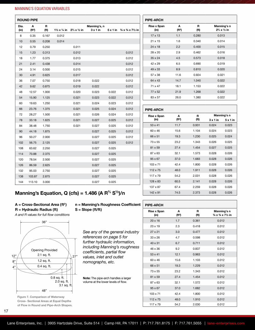
Manning’s Equation, Q (cfs) = 1.486 (A R2/3 S½)/n
A = Cross-Sectional Area (ft2 ) n = Manning’s Roughness CoefficientR = Hydraulic Radius (ft) S = Slope (ft/ft) A and R values for full flow conditions
See any of the general industry references on page 5 for further hydraulic information, including Manning’s roughness coefficients, partial flow values, inlet and outlet nomographs, etc.
Note: The pipe-arch handles a larger volume at the lower levels of flow.
ROUND PIPE
Dia.(in)
A(ft²)
R(ft) 1½ x ¼ in 22/3 x ½ in
Manning's, n 3 x 1 in 5 x 1 in ¾ x ¾ x 7½ in
8 0.35 0.167 0.012
10 0.55 0.208 0.014
12 0.79 0.250 0.011
15 1.23 0.313 0.012 0.012
18 1.77 0.375 0.013 0.012
21 2.41 0.438 0.014 0.012
24 3.14 0.500 0.015 0.012
30 4.91 0.625 0.017 0.012
36 7.07 0.750 0.018 0.022 0.012
42 9.62 0.875 0.019 0.022 0.012
48 12.57 1.000 0.020 0.023 0.022 0.012
54 15.90 1.125 0.021 0.023 0.022 0.012
60 19.63 1.250 0.021 0.024 0.023 0.012
66 23.76 1.375 0.021 0.025 0.024 0.012
72 28.27 1.500 0.021 0.026 0.024 0.012
78 33.18 1.625 0.021 0.027 0.025 0.012
84 38.48 1.750 0.021 0.027 0.025 0.012
90 44.18 1.875 0.027 0.025 0.012
96 50.27 2.000 0.027 0.025 0.012
102 56.75 2.125 0.027 0.025 0.012
108 63.62 2.250 0.027 0.025
114 70.88 2.375 0.027 0.025
120 78.54 2.500 0.027 0.025
126 86.59 2.625 0.027 0.025
132 95.03 2.750 0.027 0.025
138 103.87 2.875 0.027 0.025
144 113.10 3.000 0.027 0.025
36”
27”
48”
12”
8”
4”
Opening Provided
2.1 sq. ft.
1.2 sq. ft.
0.4 sq. ft.
0.8 sq. ft.2.0 sq. ft.
3.1 sq. ft.
PIPE-ARCH
Rise x Span (in)
A (ft²)
R (ft)
Manning's n 22/3 x ½ in
17 x 13 1.1 0.280 0.013
21 x 15 1.6 0.340 0.014
24 x 18 2.2 0.400 0.015
28 x 20 2.9 0.462 0.016
35 x 24 4.5 0.573 0.018
42 x 29 6.5 0.690 0.019
49 x 33 8.9 0.810 0.020
57 x 38 11.6 0.924 0.021
64 x 43 14.7 1.040 0.022
71 x 47 18.1 1.153 0.022
77 x 52 21.9 1.268 0.022
83 x 57 26.0 1.380 0.022
PIPE-ARCH
Rise x Span (in)
A (ft²)
R (ft)
Manning's n ¾ x ¾ x 7½ in
20 x 16 1.7 0.361 0.012
23 x 19 2.3 0.418 0.012
27 x 21 3.0 0.477 0.012
33 x 26 4.7 0.598 0.012
40 x 31 6.7 0.711 0.012
46 x 36 9.2 0.837 0.012
53 x 41 12.1 0.963 0.012
60 x 46 15.6 1.103 0.012
66 x 51 19.3 1.229 0.012
73 x 55 23.2 1.343 0.012
81 x 59 27.4 1.454 0.012
87 x 63 32.1 1.572 0.012
95 x 67 37.0 1.682 0.012
103 x 71 42.4 1.800 0.012
112 x 75 48.0 1.910 0.012
117 x 79 54.2 2.030 0.012
PIPE-ARCH
Rise x Span (in)
A (ft²)
R (ft)
Manning's n
3 x 1 in 5 x 1 in
53 x 41 11.7 0.931 0.024 0.023
60 x 46 15.6 1.104 0.024 0.023
66 x 51 19.3 1.230 0.025 0.024
73 x 55 23.2 1.343 0.026 0.025
81 x 59 27.4 1.454 0.027 0.025
87 x 63 32.1 1.573 0.028 0.026
95 x 67 37.0 1.683 0.028 0.026
103 x 71 42.4 1.800 0.028 0.026
112 x 75 48.0 1.911 0.028 0.026
117 x 79 54.2 2.031 0.028 0.026
128 x 83 60.5 2.141 0.028 0.026
137 x 87 67.4 2.259 0.028 0.026
142 x 91 74.5 2.373 0.028 0.026
Figure 7. Comparison of Waterway Cross- Sectional Areas at Equal Depths of Flow in Round and Pipe-Arch Shapes.
Lane Enterprises, Inc. | 3905 Hartzdale Drive, Suite 514 | Camp Hill, PA 17011 | P: 717.761.8175 | F: 717.761.5055 | lane-enterprises.com
17

End treatments are essential elements in protecting both the road culvert and embankment from scour and undermining. Additionally, they retain fill slope, dress-up the appearance of the inlet and outlet and provide a hydraulic efficiency that can be used for capacity analyses.
End treatments vary considerably depending on the fill slope to be retained. For the higher embankments where a culvert cannot be extended into the more gradual slopes a headwall may be required. Where the slope permits the use of more subtle treatments rip-rap armoring details may be employed. In any event the inlet and outlet should have a toe wall of sufficient depth to prevent flows from scouring or undermining the culvert ends.
Metal flared end sections provide an economical solution with hydraulic efficiencies when a full headwall is not necessary. The ends are beveled and flared and include a toe plate to eliminate the construction of a concrete toe wall.
Flared end sections are made from either galvanized steel, aluminized steel, or aluminum alloy for both round and pipe-arch shapes. The end sections are easily joined to the culvert ends using standard connecting hardware to form a continuous, convenient one-piece structure. The integrated toe plate is punched to accept an optional 8-in toe plate extension.
SLOPEThe beveled profile blends into the embankment and provides soil retention characteristics. The slope of the embankment does not need to match that of the end section, as the fill can be gradually transitioned to meet the top edge of the end section. As shown on the following page, the slope varies from 2.5:1 to 1.5:1 over the size range.
As mentioned above, the integrated toe plate with standard depth H (see detail on the following page) is punched to accept an optional 8-in toe plate extension.
FLAREThe width and flare of the end section creates the funneled shape that minimizes hydraulic losses. The entrance loss coefficient for an end section conforming to fill slope is 0.5 per the NCSPA Design Manual. The tables on the following page list dimensions corresponding to the diagram at right.
STEP-BEVELED ENDAs an alternate to the flared end section the manufacturer can miter the pipe ends to form a beveled profile. A two-step bevel is typically fabricated to retain stiffness at the crown and added stiffness at the invert. Alternatively, the end may be a full bevel or a one-step bevel (top or bottom). The bevel slope is consistent with that used for flared end sections. With the addition of a concrete toe wall, the beveled end is usually secured by casting a concrete collar around the entire opening.
END TREATMENT
End of Pipe, Annular or Re-rolled Helical
RodHolder
1/2” ThreadedRod
Slope1
H
L
AWA
1.5 : 1 or 2 : 1

END SECTION PROPERTIES FOR ROUND PIPE
Dia. (in)
Gauge Weight (lbs)
A (in)
B (in)
H (in)
L (in)
W (in)
Slope S:1
12 16 27 6 6 6 21 24 2.50
15 16 37 7 8 6 26 30 2.50
18 16 49 8 10 6 31 36 2.50
21 16 55 9 12 6 36 42 2.50
24 16 74 10 13 6 41 48 2.50
30 16 128 12 16 8 51 60 2.50
36 16 184 14 19 9 60 72 2.50
42 14 320 16 22 11 69 84 2.50
48 14 375 18 27 12 78 90 2.25
54 12 440 18 30 12 84 102 2.25
60 12/10 610 18 33 12 87 114 2.00
66 12/10 697 18 36 12 87 120 2.00
72 12/10 720 18 39 12 87 126 2.00
78 12/10 810 18 42 12 87 132 1.50
84 12/10 850 18 45 12 87 138 1.50
90 12/10 910 24 37 12 87 144 1.50
96 12/10 985 25 35 12 87 150 1.50
END SECTION PROPERTIES FOR PIPE-ARCH
Span x Rise (in)
Equiv. Dia. (in)
Gauge Weight (lbs)
A (in)
B (in)
H (in)
L (in)
W (in)
Slope S:1
17x13 15 16 28 7 9 6 19 30 2.50
21x15 18 16 36 7 10 6 23 36 2.50
24x18 21 16 43 8 12 6 28 42 2.50
28x20 24 16 55 9 14 6 32 48 2.50
35x24 30 14 95 10 16 8 39 60 2.50
42x29 36 14 140 12 18 9 46 75 2.50
49x33 42 12 233 13 21 9 53 85 2.50
57x38 48 12 315 18 26 12 63 90 2.50
53x41 48 12 330 18 25 12 63 90 2.50
64x43 54 12 357 18 30 12 70 102 2.00
60x46 54 12 375 18 34 12 70 102 2.00
71x47 60 12/10 480 18 33 12 77 114 1.50
66x51 60 12/10 487 18 33 12 77 116 1.50
77x52 66 12/10 616 18 36 12 77 126 1.50
73x55 66 12/10 625 18 36 12 77 126 1.50
83x57 72 12/10 670 18 39 12 77 138 1.50
81x59 72 12/10 680 18 39 12 77 138 1.50
87x63 78 12/10 729 22 38 12 77 148 1.50
95x67 84 12/10 755 22 34 12 77 162 1.50
103x71 90 12/10 810 22 38 12 77 174 1.50
112x75 96 12/10 907 24 40 12 77 174 1.50
Table includes 22/3 x ½ in, 3 x 1 in and 5 x 1 in corrugated pipe-arch shapes. See the Pipe-Arch Layouts page for correlation.
END TREATMENTS
NOTES FOR ALL END SECTIONS:
1. All dimensions are nominal.
2. End sections are available in galvanized steel, aluminized steel, and aluminum alloy.
3. Reinforced edges are supplemented with stiffener angles for 60-in diameter and larger round pipe end sections.
4. Reinforced edges and center panel seams are supplemented with stiffener angles for 77x52 in and larger pipe-arch end sections.
5. Stiffener and reinforcement angles when used are of the same material as the end section.
6. Some larger sizes may require field assembly.
7. All three-piece bodies have 12ga sides and 10ga center panels (designated as 12/10).
8. Multiple panel bodies have lap seams joined by rivets or bolts.
9. Optional toe plate extension is of the same gauge and material as the end section.
HPipe Dia.
12” c. to c. (Max. Spcg.)
Elevation
Optional Toe Plate Extension
ReinforcedEdge
8” 2”H
12” c. to c. (Max. Spcg.)
Elevation
Optional Toe Plate Extension
ReinforcedEdge
8” 2”
Lane Enterprises, Inc. | 3905 Hartzdale Drive, Suite 514 | Camp Hill, PA 17011 | P: 717.761.8175 | F: 717.761.5055 | lane-enterprises.com
19

HANDLING WEIGHTS
Corrugated Steel Pipe (Galvanized and Aluminized) Approximate Handling Weights by Gauge (lbs/ft)
Corrugation Dia. (in) 18 Ga 16 Ga 14 Ga 12 Ga 10 Ga 8 Ga
1½ x ¼ in 6 4 58 5 6
10 7 822/3 x ½ in 12 8 10 12 16
15 10 12 15 2018 12 15 18 2421 14 17 21 2924 15 19 24 33 4127 22 27 37 4730 24 30 41 5236 29 36 49 62 7542 34 42 57 72 8748 38 48 65 82 10054 54 73 92 11260 81 103 12466 89 113 13772 123 149 78 161
5 x 1 in 48 39 48 65 83 10054 44 54 73 93 114
3 x 1 in 60 48 59 81 104 126Increase these 66 53 65 89 114 138values by 12%. 72 58 71 97 123 150
78 62 77 105 134 16384 68 83 113 144 17590 72 88 121 154 18796 77 94 129 165 201102 82 100 136 174 212108 106 145 186 225114 112 153 195 238120 161 206 250126 172 217 263132 180 228 276138 187 238 289 144 248 303
¾ x ¾ x 7½ in 15 13 1618 15 19 2621 18 22 3024 20 25 3427 22 27 3830 25 30 4233 27 33 4636 30 36 5042 34 42 5848 39 48 66 8354 44 54 74 9460 49 60 82 10466 66 90 11472 72 99 12478 78 107 13584 115 14590 123 15596 131 165102 139 176108 186114 196120 206
Corrugated Aluminum Alloy Pipe Approximate Handling Weights by Gauge (lbs/ft)
Corrugation Dia. (in) 16 Ga 14 Ga 12 Ga 10 Ga 8 Ga
22/3 x ½ in 12 3.2 4.0 5.515 3.9 4.9 6.8
18 4.7 5.9 8.121 5.4 6.8 9.424 6.2 7.8 10.7 13.827 7.0 8.7 12.1 15.430 7.8 9.6 13.4 17.136 11.5 16.0 20.542 18.6 23.848 21.2 27.2 32.754 23.8 30.5 36.760 33.9 40.866 37.2 44.872 48.878 52.9
84 56.93 x 1 in 30 8.9 11.2 15.5 19.9
36 10.7 13.4 18.5 23.742 12.4 15.5 21.5 27.548 14.1 17.7 24.5 31.4 37.854 15.8 19.9 27.5 35.2 42.460 17.6 22.0 30.5 39.0 47.066 19.3 24.2 33.5 42.9 51.772 26.3 36.5 46.7 56.278 28.5 39.5 50.5 60.884 30.7 42.5 54.3 65.490 45.4 58.2 70.096 48.4 62.0 74.6102 51.4 65.8 79.3108 54.4 69.7 83.9114 57.4 73.5 88.5
120 60.4 77.3 93.1¾ x ¾ x 7½ in 15 4.1 5.1
18 4.9 6.121 5.7 7.124 6.5 8.0 11.027 7.2 9.0 12.530 8.0 10.0 13.933 8.8 10.9 15.236 9.6 11.9 16.642 11.3 14.0 19.348 15.9 22.0 28.254 17.9 24.7 31.760 27.4 35.166 30.1 38.672 32.9 42.078 45.4 84 48.6

ENGINEER NOTES
Lane Enterprises, Inc. | 3905 Hartzdale Drive, Suite 514 | Camp Hill, PA 17011 | P: 717.761.8175 | F: 717.761.5055 | lane-enterprises.com
21

ENGINEER NOTES

LANE Enterprises, Inc.3905 Hartzdale Drive, Suite 514 Camp Hill, PA 17011 P: 717.761.8175 • F: 717.761.5055lane-enterprises.com
LANE Products
Corrugated Metal PipeSpiral Rib PipeCorrugated HDPE PipeCorrugated Polypropylene PipeStructural Plate Pipe and ArchesStructural Plate Box CulvertsStorm Water Collection ChambersStorm Water Management SystemsStorm Water FiltersCFT (HDPE) Water Quality UnitCMP SandfilterOpen Top Slotted DrainWelded Wire Mesh GabionsStructural Plate Headwall-Culvert SystemsCustom Fabrications (Pond Kits, Trash Racks, etc.)Long Span Bridge & Culvert ServicesRebar and Custom Powder Coatings
LANE Facilities
PENNSYLVANIA
Bedford 814.623.1191 Carlisle 717.249.8342 King of Prussia 610.272.4531 Pulaski 724.652.7747 Shippensburg 717.532.5959
VIRGINIA
Bealeton 540.439.3201 Dublin 540.674.4645 Wytheville 276.223.1051
NEW YORK
Ballston Spa 518.885.4385 Bath 607.776.3366
NORTH CAROLINA
Statesville 704.872.2471
TEXAS
Temple 254.727.3346
CORPORATE HEADQUARTERS
Camp Hill 717.761.8175
An Employee-Owned Company
plasticpipe.org
ncspa.org
© 2021 Lane EnterprisesRAKZID LLC-9/21-AA