CMP CIEL High Voltage Cable Glands - CMP Cast Integral Earth Lug

1
Course Guidelines/Handouts to
CMP 388.3 Object Oriented Software Engineering
For the Course Prescribed by Pokhara University
Compiled/Prepared By: Bibek Ropakheti
Lecturer Cosmos College of Management and Technology
Tutepani, Satdobato Lalitpur, Nepal.
2
This is to aware all of you that, this note is not complete within itself
and should be used as a complementary material along with the text
books and reference books.
The basic book that covers almost all the topics is Fifth Edition of
Software Engineering: A Practitioner’s Approach by Roger S.
Pressman.
Bibek Ropakheti

Object Oriented Software Engineering Syllabus
3 Bibek Ropakheti
CMP 388.3 Object Oriented Software Engineering (3-1-0)
Course Objectives: The course objective is to provide required knowledge on the various issues of software project management and related tasks including planning, design, development implementation, maintenance and cross life cycle activities using object oriented concepts and models. Course Contents:
1. Introduction (5hrs) Page 6 History of software engineering, role of software engineering in system design. The software development life cycle . Relationship of software engineering to other areas of computer science and other disciplines . Software Process Models, Linear Model. The Prototyping Model, The RAD Model, Evolutionary Models, Waterfall Model, Incremental Model, Spiral Model etc. 2. Project Management Concepts (2hrs) Page 37 The Management Spectrum, People, The Product, The Process, The project. 3. Project Planning (5hrs) Page 41 Software scope, Feasibility: Importance, Feasibility assessment, Economic, technical Operational and Schedule Feasibility, Resources: human, reusable software, environment, Project Estimation, The make/buy decision, outsourcing, Project scheduling tracking 4. Risk Analysis and Management (3hrs) Page 42 Software risks, Risk Identification, Risk Projection, Risk Refinement, risk Mitigation, Monitoring and Management, Safety Risks and Hazards.
Theory Practical Total Sessional 50 50 Final 50 50 Total 100 100

Object Oriented Software Engineering Syllabus
4 Bibek Ropakheti
5. Software Qualities (4hrs) Page 47 Classification of software qualities, representative qualities, quality requirements based on application areas, Quality Concepts, Software Quality Assurance, Software Reviews, Formal Technical Reviews, Software Reliability, Software Configuration Management, SCM Standards. 6. System Engineering Principles (5hrs) Page 63 Business Process Engineering, Product Engineering, Requirements Engineering, Requirements Elicitation, Analysis and Negotiation, Specification, Validation, and Management, System Modeling (in detail): Data (ERD), Functional (DFD, CFD), Behavioral (STD ) etc. 7. Software Testing (4hrs) Page 81 Software Testing fundamentals, Importance of Testing, Test Case Design White Box Testing, Black Box Testing, Unit Testing, Integration Testing, Validation Testing, System Testing Verifying and Debugging, Symbolic execution. 8. Object Oriented Fundamentals (2hrs) Page 86 OO Paradigm: Classes, objects, attributes, operations, methods, services, messages, encapsulation, inheritance, polymorphism, etc. 9. UML (6hrs) Page 91 Unified Modeling Language Fundamentals, UML, notations, Structural Models: (concepts: class, object, relationship, interfaces, packages, instances) Class Diagram, and Object Diagram, Behavioral Models (concepts: interactions, scenarios, use cases, event, signal, process), Use Case Diagram, Interaction Diagram, Collaboration Diagram, State Transition Diagram, Activity Diagram, Architectural Models (concepts: components, deployment, collaboration, patterns, etc), Component Diagram, Deployment Diagram, UML, based any CASE tool and its use.
Object Oriented Software Engineering Syllabus
5 Bibek Ropakheti
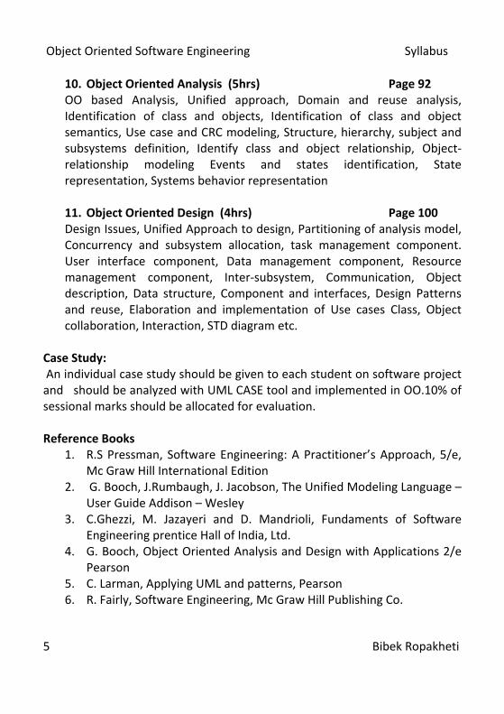
10. Object Oriented Analysis (5hrs) Page 92 OO based Analysis, Unified approach, Domain and reuse analysis, Identification of class and objects, Identification of class and object semantics, Use case and CRC modeling, Structure, hierarchy, subject and subsystems definition, Identify class and object relationship, Object- relationship modeling Events and states identification, State representation, Systems behavior representation 11. Object Oriented Design (4hrs) Page 100 Design Issues, Unified Approach to design, Partitioning of analysis model, Concurrency and subsystem allocation, task management component. User interface component, Data management component, Resource management component, Inter-subsystem, Communication, Object description, Data structure, Component and interfaces, Design Patterns and reuse, Elaboration and implementation of Use cases Class, Object collaboration, Interaction, STD diagram etc.
Case Study: An individual case study should be given to each student on software project and should be analyzed with UML CASE tool and implemented in OO.10% of sessional marks should be allocated for evaluation. Reference Books
1. R.S Pressman, Software Engineering: A Practitioner’s Approach, 5/e, Mc Graw Hill International Edition
2. G. Booch, J.Rumbaugh, J. Jacobson, The Unified Modeling Language –User Guide Addison – Wesley
3. C.Ghezzi, M. Jazayeri and D. Mandrioli, Fundaments of Software Engineering prentice Hall of India, Ltd.
4. G. Booch, Object Oriented Analysis and Design with Applications 2/e Pearson
5. C. Larman, Applying UML and patterns, Pearson 6. R. Fairly, Software Engineering, Mc Graw Hill Publishing Co.

OOSE Chapter 1: Introduction
6 Bibek Ropakheti
Chapter 1 Introduction Programs, Software and Software Engineering Good Software, Types of Software History Software Process Model Program Programs are simple the source codes and object codes those fulfill some specific purpose. Examples are those you create in your laboratories, like a program to add two numbers or a program that stores the records of n number of students with their class performance. Software Over the years the developers have concluded that software is not merely the chunk of codes that performs specific function, rather software is a system that encompasses many other related materials except code. An equation will clarify the concept of software: Software= Programs+ Good User Interface+ User Manuals+ Documentations According to different contributors, software is defined as:
According to Roger Pressman [Software Engineering: A Practitioner’s Approach], “Software encompasses programs that execute within a computer of any size and architecture, contents that are presented as the computer programs execute and documents that encompass all forms of electronic media.”
Ian Somerville [Software Engineering] described software as: “A system of number of separate programs, configuration files needed to setup these programs, system documentation describing the structure of the system and user documentation describing the way to use the software.”
The definition of software followed at Princeton University says: “Computer software in general used to describe a collection of computer programs, procedures and documentation that performs certain tasks on a computer system.”
OOSE Chapter 1: Introduction
7 Bibek Ropakheti
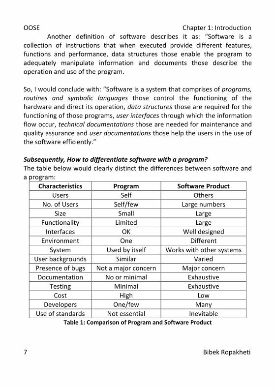
Another definition of software describes it as: “Software is a collection of instructions that when executed provide different features, functions and performance, data structures those enable the program to adequately manipulate information and documents those describe the operation and use of the program. So, I would conclude with: “Software is a system that comprises of programs, routines and symbolic languages those control the functioning of the hardware and direct its operation, data structures those are required for the functioning of those programs, user interfaces through which the information flow occur, technical documentations those are needed for maintenance and quality assurance and user documentations those help the users in the use of the software efficiently.” Subsequently, How to differentiate software with a program? The table below would clearly distinct the differences between software and a program:
Characteristics Program Software Product Users Self Others
No. of Users Self/few Large numbers Size Small Large
Functionality Limited Large Interfaces OK Well designed
Environment One Different System Used by itself Works with other systems
User backgrounds Similar Varied Presence of bugs Not a major concern Major concern Documentation No or minimal Exhaustive
Testing Minimal Exhaustive Cost High Low
Developers One/few Many Use of standards Not essential Inevitable
Table 1: Comparison of Program and Software Product
OOSE Chapter 1: Introduction
8 Bibek Ropakheti
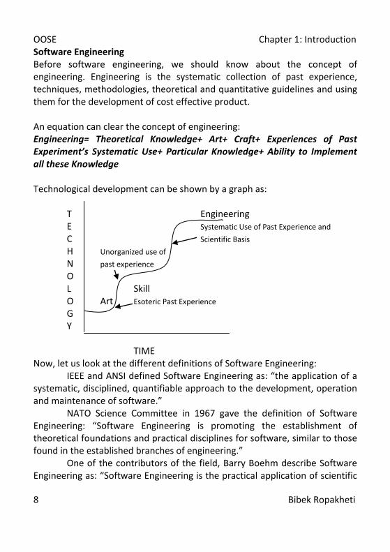
Software Engineering Before software engineering, we should know about the concept of engineering. Engineering is the systematic collection of past experience, techniques, methodologies, theoretical and quantitative guidelines and using them for the development of cost effective product. An equation can clear the concept of engineering: Engineering= Theoretical Knowledge+ Art+ Craft+ Experiences of Past Experiment’s Systematic Use+ Particular Knowledge+ Ability to Implement all these Knowledge Technological development can be shown by a graph as: T Engineering E Systematic Use of Past Experience and C Scientific Basis H Unorganized use of
N past experience
O
L Skill O Art Esoteric Past Experience
G Y TIME
Now, let us look at the different definitions of Software Engineering: IEEE and ANSI defined Software Engineering as: “the application of a
systematic, disciplined, quantifiable approach to the development, operation and maintenance of software.”
NATO Science Committee in 1967 gave the definition of Software Engineering: “Software Engineering is promoting the establishment of theoretical foundations and practical disciplines for software, similar to those found in the established branches of engineering.”
One of the contributors of the field, Barry Boehm describe Software Engineering as: “Software Engineering is the practical application of scientific
OOSE Chapter 1: Introduction
9 Bibek Ropakheti
knowledge in the design and construction of computer programs and the associated documentation required to develop, operate and maintain them.
Fritz Bauer gave the definition as: “The establishment and use of sound engineering principles in order to obtain economically software that is reliable and works efficiently on a real machine is Software Engineering.”
According to the book, [Software Engineering], by Ghezzi, Jazayeri and Mandrioli: “Software Engineering is the field of computer science that deals with the building of software systems that are so large or so complex that multiple versions with many years of service period. During their lifetime they undergo many changes: to enhance the existing features, to add new or remove old features, or to be adapted to run in the new environment. So, in short, the application of engineering to software is software engineering.”
Sommerville in 1995 defined Software Engineering as: “Software Engineering is concerned with the theories, methods and tools that are needed to develop the software products in a systematic and cost effective way.”
Parnas in 1978 gave a precise meaning to Software Engineering: “Multi-person construction of multi-version software is Software Engineering.”
R. Fairly said that: “Software Engineering is the technological and managerial discipline concerned with the systematic production and maintenance of software products that are developed and modified on time and within cost estimates.”
Roger S. Pressman defined Software Engineering as a discipline that integrates process, methods and tools for the development of quality standard computer software.
R. Mall in his book, [Fundamentals of Software Engineering], he conclude that, developing a high quality software with the use of knowledge of past experience, by choosing among multiple alternatives the best one that is cost effective is software engineering. So, again conclusion is: Software Engineering is the enduring process of development of standard and good software by following standard techniques and tools in a professional environment that accomplish its desired goals. Along with that the software thus developed should also be maintainable, reusable and upgradable.

OOSE Chapter 1: Introduction
10 Bibek Ropakheti
Now, I aforementioned a term good software, but what is a good software? For software to be good, it should have some attributes: Correctness {Software must be correct, i.e. it should do what it is meant to.} Maintainability {If a problem occurs in future, software should be mendable.} Dependability {Software must be reliable, secure & safe enough to be used.} Efficiency {If software uses its resources effectively, it’s efficient.} Usability {If software is easy to use and understand, it’s usable.} Integrity {System’s ability to withstand attacks to its security is integrity.} Few other general attributes are: performance, verifiability, evolvability, portability, interoperability, productivity, timeliness, visibility, understandability, malleability, etc. Types of Software According to the use of the software it has been categorized as: System Software:
Software that helps to run the computer hardware and the computer system is system software. Its purpose is to hide the hardware and memory details from application programmer. It includes operating systems, device drivers, diagnostic tools, servers, utilities etc. Programming Software:
Programming software provides tools to assist programmers in writing programs and software codes, preparing technical documentations etc. using different languages in a more convenient way. It includes text editors, compilers, interpreters, linkers, debuggers and so on. Integrated Development Environment merges these all in a bundle. Application Software:
Application software allows end users to accomplish one or more specific tasks. It includes industrial, business, educational, medical software, databases and computer games, etc. Business is where it is mostly used. From another perspective, i.e. how software is made, software may be: Generic Software:
Software produced by a development organization and sold on to open market to any customer able to buy them is generic or shrink-wrapped software.
OOSE Chapter 1: Introduction
11 Bibek Ropakheti
Tailored Software: Tailored or bespoken software is commissioned by a particular
customer and is developed by a software contractor. Generally, software may be:
Embedded software Engineering/Scientific software Product line software Web Application AI software Ubiquitous Net sourcing Open Source, etc.
History When was the concept of software and software engineering started?
During the early decades, the primary challenge was in the development of hardware that reduced the cost of storing and processing data. There were general purpose hardware and software was custom build.
During late 50’s to early 60’s the programmers use to code the software on the basis of their experience and techniques. The basic language they used was low level ones. They were not too lengthy and programmers use to have their own individualistic style of writing programs. This technique was often termed exploratory programming style. The product software was in its initial stage, i.e. developed, sold or distributed to very small number of customers and used by very few people. Almost every responsibility of making a program run was limited to programmer, i.e. he had to write, got it run and fix all the bugs. Designs were just made in head.
With the introduction of semiconductor technology computers became faster causing the development of high level programming languages like COBOL, FORTRAN and ALGOL etc. leading to the start of second era of software development. These languages helped programmers to develop lengthier programs but, the same style was followed which was going to change.

OOSE Chapter 1: Introduction
12 Bibek Ropakheti
During 60’s the concept of following the common practice and pattern while coding was developed with the development of multiuser involvement and multiprocessing capabilities. For that flow charting technique developed, which basically focused on use of focusing control flow to solve the problem. Interactive techniques were used and software reached a new sophistication level. Real time systems could collect, analyze and transform data from multiple sources thereby reducing the computing time considerably. Database based systems were the main focus. Ultimately, entrepreneurs from industry and government developed the product software packages which led to a huge income source.
The third generation of software development focused on the removal of unstructured GOTO statements from the programs with the use of loops. Basically, Dijkstra in 1968 published an article, “GOTO statements considered harmful”, that suggested and was even followed by most not to use GOTO, giving birth to the new approach of programming, structured programming methodology.
This structured programming led to the development of development of software with the approach which followed the methodology where software would first be analyzed, modeled and designed before developing into code. This methodology was termed structured system design or structured system analysis and design. Data structure oriented design and data flow oriented design were the varied approach of structured methodology. Structured approach helped the software industry to address the demand of then market which was hugely reliable on Global and Local Area Networks with high bandwidth digital communication. The approach of functionality and modularity development helped to make up the software demands of multiprocessing PCs. In this era, rate of hardware declined but the software sales were very good. More money was in software than PCs.
Recently, in late 90’s and early millennium, displacing the conventional software development methods, the new approach of software development, namely object oriented software development has evolved. It was termed fourth era of software. Expert systems to work in artificial neural networks have been the requirement in this era. General problems have been the hardware configuration enhancement to be matched by software. New
OOSE Chapter 1: Introduction
13 Bibek Ropakheti
demands of software in the changing environment and demands of faultless software have been the market needs.
Today the scenario is different. The problem is different. Now, hardware has tremendous computing potentials and software provides the mechanism that enables us to harness and tap this potential. The primary challenge now is to improve the quality of computer based solution i.e. software.
Even more recently, agile software development is a newer approach. Generic programming, extreme programming, adaptive software development and dynamic systems development methods are the newer addition to software development strategy.
And it will go on.
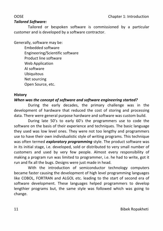
Early Years Second Era Third Era Forth Era Batch Orientation
Multi User Systems
Distributed Systems
Powerful Desktop Systems
Limited Distribution
Database Incorporated
Embedded Intelligent
O.O. Analysis
Real Time Low Cost Software Expert System Custom Software
Product Software
Consumer Impact Artificial Neural Network Partial Computing
Table 2: Overview of History of Software Development Trend But, what was the actual cause? And the precise answer is Software Crisis. It describes the impact of rapid increases in computer power and the complexity of the complexity of the problems which could be tackled. It refers to the difficulty of writing correct, understandable and verifiable programs. Software Crisis was the term coined by F. L. Bauer at the first NATO Software Conference in 1968 at Garmisch, Germany. It occurred due to the sudden introduction of third generation computes. Its causes were complexities, expectations and changes. With the changes in the computing speed and capabilities of the hardware, the expectations in the performance of software were exponentially increased. But, like the mass production of hardware, software could not be developed ultimately a crisis occurred.
OOSE Chapter 1: Introduction
14 Bibek Ropakheti
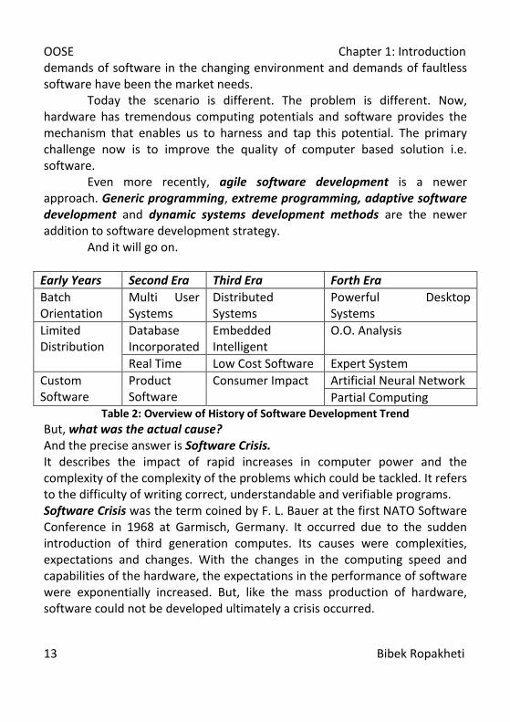
hardware cost/software cost
1960 year
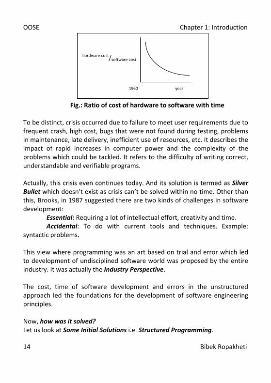
Fig.: Ratio of cost of hardware to software with time To be distinct, crisis occurred due to failure to meet user requirements due to frequent crash, high cost, bugs that were not found during testing, problems in maintenance, late delivery, inefficient use of resources, etc. It describes the impact of rapid increases in computer power and the complexity of the problems which could be tackled. It refers to the difficulty of writing correct, understandable and verifiable programs. Actually, this crisis even continues today. And its solution is termed as Silver Bullet which doesn’t exist as crisis can’t be solved within no time. Other than this, Brooks, in 1987 suggested there are two kinds of challenges in software development:
Essential: Requiring a lot of intellectual effort, creativity and time. Accidental: To do with current tools and techniques. Example:
syntactic problems. This view where programming was an art based on trial and error which led to development of undisciplined software world was proposed by the entire industry. It was actually the Industry Perspective. The cost, time of software development and errors in the unstructured approach led the foundations for the development of software engineering principles. Now, how was it solved? Let us look at Some Initial Solutions i.e. Structured Programming.

OOSE Chapter 1: Introduction
15 Bibek Ropakheti
Structured programming focused on coding in a disciplined way. Even though it was not the complete solution, but it minimized the effect of one module on another. Structured programming led to the structured designing principles. The approach of top down design minimized coupling between modules and maximized cohesion. Even though structured design tried to solve all the problems but it was again not the complete solution. The real solution was structured analysis. Now, structured analysis focused on understanding the problem. Then structured design would look for the ‘how’ to solve and finally structured programming would carry out the good design into the program. New concepts like Data Flow Diagrams those models the system’s functions, Control Flow Diagrams those models the system’s control flow, Entity Relationship Diagrams those helps to understand the relationship between the systems’ data groups and Program Structure Charts those designs the optimal program modules were introduced. But the expectation was for a more organized, more fruitful technique. And the solution was Structured Methodologies. Structured Methodologies encompasses all the individual accomplishments of structured analysis, structured design and structured programming. New things were introduced that specifies:
• Set of activities that need to be came out. • Sequence and relationship between them. • Tools and techniques to use. • The way to record these tasks, i.e. documentation.
Proposed system has the property of being:
• Graphical. • Top down partition able.

OOSE Chapter 1: Introduction
16 Bibek Ropakheti
• Clearly separates physical model that is concerned with system implementation and logical model that is concerned with functionality or essence.
As of any methodology, structured methodology integrates all the activities of SDLC and has well defined scope of coverage standard following the conventional benchmark. The simultaneous documentation of technical and user documents are done. All the steps of project management from estimation, scheduling, risk management, quality management and configuration management are addressed in structured methodology. Structured methodology came out to be beneficial for professionals like managers, quality assurance personals, auditors, etc. But, what are the recent developments those are being the major influencing factors in the way methodologies are being looked at? Let us describe few of the factors as: Evolution of End User Computing With time end users are more familiar with the computer technology and are aware of potentials in the field. More software is and is to be developed where the users of the system must be involved. Their involvement in the system development process and higher interaction would come out to be more fruitful with the system and system personals. Emergence of CASE tools CASE stands for Computer Aided Software Engineering. Use of computer based subsidy to develop a model, design and documentation of software is possible with the use of CASE tools. Many of the CASE tools even provide methodology specific support. CASE helps in integration of SDLC activities, maintaining standards, promoting cost efficiency, removal of monotony, self documentation etc. Whereas loss of data, cost increment with sophistication and dependency are few negative factors associated with CASE tools. But, it’s true that CASE tools are assumed to be the panacea for all the problems.
OOSE Chapter 1: Introduction
17 Bibek Ropakheti
Use of Prototyping Prototyping is the process of starting any software project with the assumptions. Prototyping helps in the removal of initial vagueness. Prototypes are used to simulate the business functionality, its scope of coverage and sustainability to the organization. Relational Database Use of database by the end users directly with the minimum programming skill was the demand with relational databases. With time databases are being platform independent helping the programmers to use the databases without any concern to the user interface. Oracle and Ingues are the modern day database tools that are usable under different platforms. General database management tools export data while changing the platforms. But overall, all of them have standard SQL, report generators, and query optimizer. Database in future will have additional features like accepting documents from separate sources, handling different document structures, providing thesaurus, GUI based UIs and so on. Object oriented approach Object oriented approach attempts to completely alter the traditional methodologies of software developments. In object oriented approach programmer is more like a director of the show who handles the actors of the show called objects. They are like actors with specific set of skills and all the actors have special relationships between each other. Concept of responsibilities, behavior, attributes, inheritance, polymorphism, abstraction and encapsulation were introduced in this approach. The most important feature, reusability is the major focus of this approach. Java and C# are the object oriented programming languages.

OOSE Chapter 1: Introduction
18 Bibek Ropakheti
Graphical User Interface Giving standard look and feel to the application in order to achieve user attraction is through GUI (gooey). Typically, GUI uses menus, icons, tiled windows, dialog boxes, support for pointing devices, scrollbars, etc. GUI enforces consistency by restricting developers to develop software that supports features of GUI. Due to the easy familiarization to the application, the end users could easily adopt to the newer applications. Drawing and CAD programs are best suited to GUIs since they manipulate objects, lines and curves as well as fill areas with colors. We can say that the market is so familiar to the systems, thanks to GUI. End users would not have used computer systems if the software would have been limited to CUIs. Now as we have discussed different factors in the development of different methodologies, let us clarify what is methodology and how does it works? The formal method of standard software development is software development methodology. “WINNERS DO NOT DO DIFFERENT THINGS THEY JUST DO THINGS DIFFERENTLY” Methodology doesn’t replace the professionals or tools, rather it makes a good system and a better professional. The ultimate aim of any organization is to build better systems, not to follow an excellent methodology. Then, how to choose the right methodology? There is no obvious solution that’s suitable depending upon the problems faced and the setting in which a business is done. The objectives of adopting a methodology may vary. So, any suitable methodology for one case may not be suitable at another case. Answering few of the questions may be helpful in adopting the proper methodology. Scope and level of details: What are the scopes and business? Will the software be applicable to various types of systems that your
organization builds? Integration with other tools:
OOSE Chapter 1: Introduction
19 Bibek Ropakheti
What facilities do this methodology provides to facilitate project management?
Easy of learning and use? What level of training does this methodology require for use? What’s the support available from the vender for training and
consultancy? But, how is any methodology implemented? Some steps are to be followed before implementing any methodology. Understanding the requirement for the type of application the software
develops. Understanding the problems being faced frequently. Looking out for the best methodology. Involving the upper level management in the whole process and educate
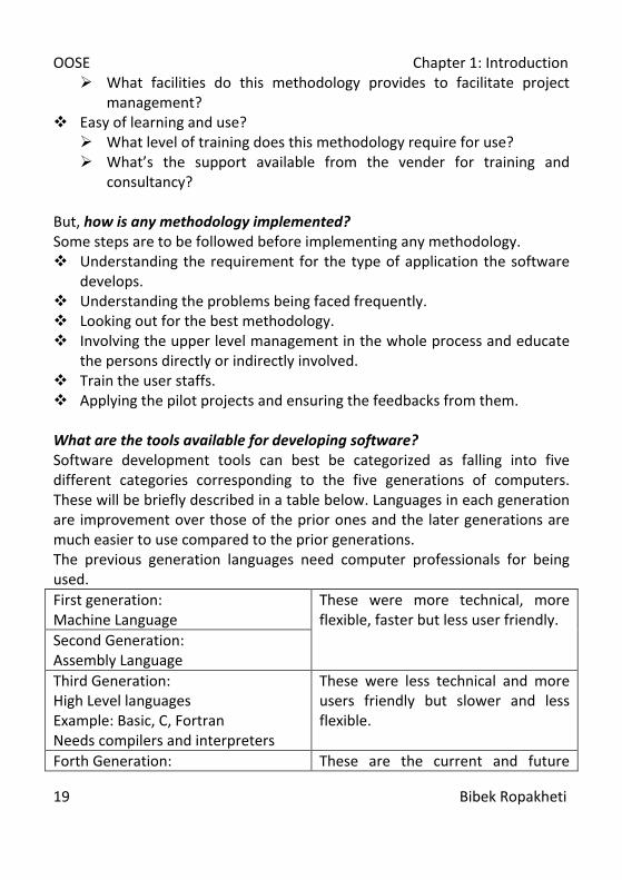
the persons directly or indirectly involved. Train the user staffs. Applying the pilot projects and ensuring the feedbacks from them. What are the tools available for developing software? Software development tools can best be categorized as falling into five different categories corresponding to the five generations of computers. These will be briefly described in a table below. Languages in each generation are improvement over those of the prior ones and the later generations are much easier to use compared to the prior generations. The previous generation languages need computer professionals for being used. First generation: Machine Language
These were more technical, more flexible, faster but less user friendly.
Second Generation: Assembly Language Third Generation: High Level languages Example: Basic, C, Fortran Needs compilers and interpreters
These were less technical and more users friendly but slower and less flexible.
Forth Generation: These are the current and future

OOSE Chapter 1: Introduction
20 Bibek Ropakheti
Non procedural, Object Oriented Implements Query Languages, Report Generators and Application Generators
developments.
Fifth Generation: Natural language Processing
Table 3: Generations of Tools Now, which is the most suitable tool? The answer is it depends: Depends upon the processing procedure. Depends upon the developing software. Depends on the plan you have made. Depends on the knowledge of the tools. Generally, third generation tools are suitable for the professionals and forth generation tools for a non computer specialist as it need no interior technologies in detail. Fourth Generation Tools These tools are easier for programmers to use. The nonprocedural languages fall under this category. Non procedural language doesn’t focus on “how to accomplish the task?” rather it just suggests “what to do?” 10 percent of the statements in 4GL are that of 3GL. Basically, five types of languages fall into the categories of 4GL: Query Languages Query languages allow users to ask questions about or retrieve information from database files by requests. Query languages have specific grammar, vocabulary and syntax that must be mastered but it is relatively simple. The most powerful and popular query language today is Oracle. Report Generators Report generators allow users to retrieve information in the form of reports. Report generators however can’t alter or manipulate the database information.
OOSE Chapter 1: Introduction
21 Bibek Ropakheti
Application Generators Application generators are standardized building blocks that can be used to assemble rather than develop software. Application generators translate specifications into application programs. The specifications describe the problem or task to be performed and are used by the application generator to create the needed application system. The valuable benefit of the application generation approach of system development is the software reusability. Reusing previously developed modules, packages, components, software development methodologies, analysis data and test information has been found attractive and will receive as a method for improving software productivity. Decision Support Systems Decision support systems and financial planning languages combine special interactive computer programs and some special hardware to allow the high level managers to bring data and information together from different resources and manipulate it in new ways to do analysis, make projections and make long term planning decisions. Some Micro Computer Applications Some microcomputer applications can also be used to create specialized applications. For example: creating a mark sheet using excel. Fifth Generation Tools: Natural Language Processing These are similar to query languages with a major difference that it neither needs the knowledge of specific vocabulary, syntax or grammar for programming. It’s similar to human speech and even misspellings gives out the desired results. These make computer smarter and relates to expert systems based on Artificial Intelligence. Introduction to Software Development Life Cycle OR Software Process The software process consists of activities which are involved in developing software products. From Technical point of view, software process is defined as a framework for the tasks that are required to build high quality software. A process defines who is doing what, when and how to reach a certain goal.
OOSE Chapter 1: Introduction
22 Bibek Ropakheti
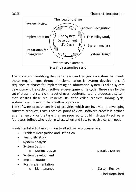
Fig: The system life cycle
The process of identifying the user’s needs and designing a system that meets those requirements through implementation is system development. A sequence of phases for implementing an information system is called system development life cycle or software development life cycle. These may be the set of steps that start with a set of user requirements and produces a system that satisfies these requirements. Its often called problem solving cycle, system development cycle or software process. The software process consists of activities which are involved in developing software products. From Technical point of view, software process is defined as a framework for the tasks that are required to build high quality software. A process defines who is doing what, when and how to reach a certain goal. Fundamental activities common to all software processes are:
• Problem Recognition and Definition • Feasibility Study • System Analysis • System Design
o Outline Design o Detailed Design • System Development • Implementation • Post Implementation
o Maintenance o System Review
The idea of change System Review
Problem Recognition
Implementation Feasibility Study
System Analysis Preparation for Changeover System Design
System Development
The System
Development Life Cycle
OOSE Chapter 1: Introduction
23 Bibek Ropakheti
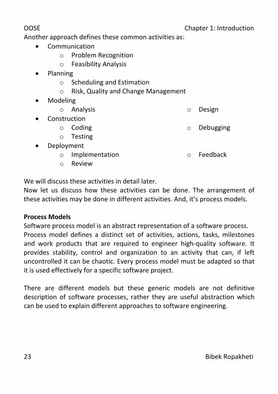
Another approach defines these common activities as: • Communication
o Problem Recognition o Feasibility Analysis
• Planning o Scheduling and Estimation o Risk, Quality and Change Management
• Modeling o Analysis o Design
• Construction o Coding o Testing
o Debugging
• Deployment o Implementation o Review
o Feedback
We will discuss these activities in detail later. Now let us discuss how these activities can be done. The arrangement of these activities may be done in different activities. And, it’s process models. Process Models Software process model is an abstract representation of a software process. Process model defines a distinct set of activities, actions, tasks, milestones and work products that are required to engineer high-quality software. It provides stability, control and organization to an activity that can, if left uncontrolled it can be chaotic. Every process model must be adapted so that it is used effectively for a specific software project. There are different models but these generic models are not definitive description of software processes, rather they are useful abstraction which can be used to explain different approaches to software engineering.

OOSE Chapter 1: Introduction
24 Bibek Ropakheti
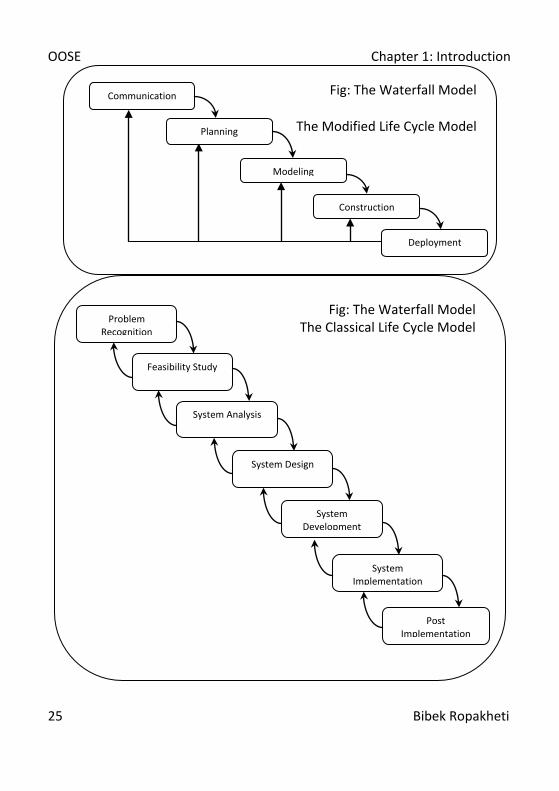
The Waterfall Model
Fig: The Waterfall Model
The Classical Life Cycle Model
Communication
Deployment
Planning
Modeling
Construction
OOSE Chapter 1: Introduction
25 Bibek Ropakheti
Fig: The Waterfall Model The Classical Life Cycle Model
Problem Recognition
Feasibility Study
Post Implementation
System Analysis
System Design
System Development
System Implementation
Fig: The Waterfall Model
The Modified Life Cycle Model
Communication
Deployment
Planning
Modeling
Construction

OOSE Chapter 1: Introduction
26 Bibek Ropakheti
The Incremental Model
The RAD Model
Team n Communication
Planning
Team 2 Modeling
Team 1 Construction
Deployment 60-90 days
Fig: The RAD Model
M X
D
P
C
M
M
X
X
C
P
M
X
D
So
ftw
are
Func
tiona
lity
and
Feat
ure
C
M X D P
C M X D
P
C M X D
P
Project Calendar Time
Communication Planning Modeling
Construction Deployment
C
D X
M P
Increment n
Increment 2
Increment 1
Fig: The Incremental Model
OOSE Chapter 1: Introduction
27 Bibek Ropakheti
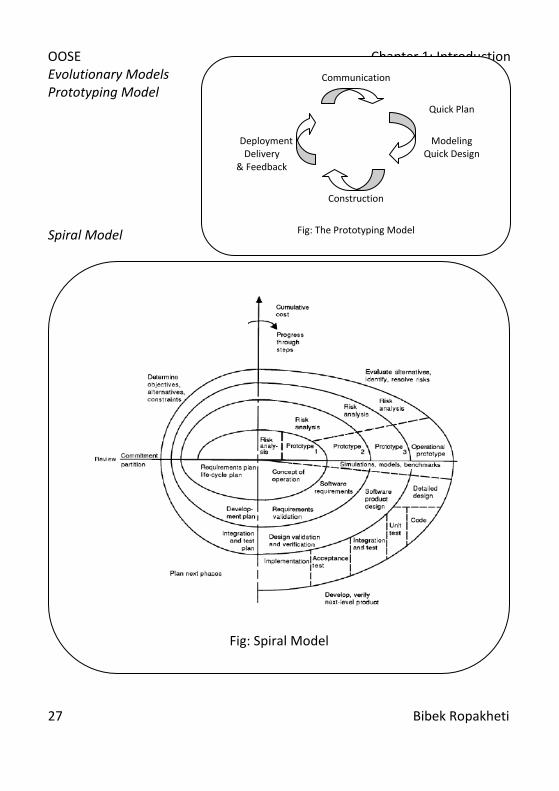
Evolutionary Models Prototyping Model Spiral Model
Fig: Spiral Model
Communication
Quick Plan
Deployment Modeling Delivery Quick Design & Feedback
Construction
Fig: The Prototyping Model

OOSE Chapter 1: Introduction
28 Bibek Ropakheti
Formal Development Method
Now let us discuss something about the stages of the SDLC. Problem Recognition Establishing what is the problem is recognizing the problem. Converting the problem into the opportunities and solution may need to understand the problem well. Whenever there is an opportunity or problem in the existing system or when a system is being developed for the first time, the designing of new information processing system is to be considered. This opportunity is led due to the evolution of new product, plant, branch, market or process. Other reasons may be the failure, inefficiency or errors in the existing system that can’t be easily exterminated. Due to this the opportunity for new system is perceived. And on identification of these problems, these problems are defined and a general direction for solving the problems is also determined. The project boundaries are defined. The management also establishes the terms of references and resources to be used for the project. Final output of this stage is Terms of Reference. Feasibility Study
Fig: Formal Method of Software Development
Fig. Formal Transformation
Requirement Definition
Formal Specification
Formal Transformation
Integration and Testing
Formal Specification
Executable Program
T
T
T
T
T(n+1
R
R
R
P
P
P
P
P(n+1)

OOSE Chapter 1: Introduction
29 Bibek Ropakheti
A feasibility study is a short descriptive study that aims on answering overall objectives of the organization and the system, implementation of the system and efficiency of the system from different discernment. Generally feasibility study is done by accomplishing Information Assessment, Information Collection and Report Writing. Hence, final output of feasibility study is a feasibility study report. System Analysis System analysis is a detailed study of various operations performed by a system and their relationships within and outside the system. System analysis includes defining the system, modularizing the different components and understanding the nature, function and interrelationships of various subsystems. Analysis could be done with the help of various tools like reviewing documents, observing situation, conducting interviews, preparing questionnaire to the administration and so on. Analysis is completed by developing different logical solutions to the problem. The output is the starting point for gathering these specifications. From this, it is possible to find the kinds of inputs, data base, methods, procedures, and data communications are employed. A detailed report is then prepared duly signed by the team of system analysts and approved by the user group. General tools used for analysis are DFD, Data Dictionary, ERD, STD, Decision Tree, Decision Table, Structured English, Flowcharts, Layout charts, Class Diagrams, Object Diagrams, Sequence Diagrams, Collaboration Diagrams, State-Chart Diagrams, Activity Diagrams, Component Diagrams, Deployment Diagrams, etc. System Design A system design is a solution to a business problem. Design demands the translation of the requirements uncovered in systems analysis into possible
OOSE Chapter 1: Introduction
30 Bibek Ropakheti
way of meeting them. The system design focuses on the detailed implementation of the system recommended in the feasibility study and system analysis. System design transforms software requirement specifications into software design. The major design objective is to have a good quality in the features and functionalities. The good design has some desirable features like functionality, efficiency, flexibility, portability, security, reliability, economy and usability. Design process must be user centered, participative, experimental, iterative, and user supportive. The output of the system design process is the design documents that can directly be transformed into the code. System design helps in efficient code development. System Development System development implies the process of coding, testing and debugging the system. The transformation of the system design document into tangible form of program and procedure is system development. The system development process is widely subcategorized into: Coding Testing Debugging Coding The input to the coding phase is the design document. During the coding phase, different modules identified in the software design document are coded according to the respective module specification. While coding, the code needs to maintain some characteristics like simplicity, readability, usability, transportability and good documentation. Once coded, it needs reviews. The process of reviewing the code may be accomplished through different techniques like, code walkthrough, code inspection, clean room testing etc. Code reviewing is done by different categories of people involved in software development like author, moderator, inspector, review team, etc. code

OOSE Chapter 1: Introduction
31 Bibek Ropakheti
walkthrough is an informal technique of code analysis. In a walkthrough session, the code is reviewed by the team and then in a special session of discussion the special issues involved with the codes are discussed. Code inspection is another way to insure quality of the code. In inspection, common types of issues are focused to be solved. Coding is followed by testing. Testing Testing is to identify all the defects existing in a software product. Software testing is the process of executing a program to locate an error. A good testing is one that has the high probability of finding undiscovered errors. Even though testing helps in the removal of errors from the program, it can’t eradicate all the defects. There have been different types of testing. They are: Unit Testing Integration Testing System Testing
Acceptance Testing Stress Testing Regression Testing
Debugging There has been a quotation that “Testing is not debugging and debugging is not testing”. Debugging is an activity after the testing where the cause of the errors detected during testing are identified. Simply, the process of fixing the bugs is debugging. There are different techniques of debugging. They are: Brute force debugging is a technique where program is loaded with print statements to print the intermediate values with the hope that some printed values will help identify the source of the errors. It is the most common technique of debugging. Backtracking is the process where the source code is traced backwards until the error is discovered. It becomes tedious when the length of source code to be backtracked is huge.
OOSE Chapter 1: Introduction
32 Bibek Ropakheti
Cause Elimination method lists all the probable causes and tests are carried out to eliminate each cause. A related technique of identification of the error from the error symptom is the Software Fault Tree Analysis. Debugging by Induction is a process that locates the data, organizes it and devises a hypothesis that is to be proved. Debugging by Deduction is a process where possible causes determined and data is used to eliminate causes using hypothesis. Program slicing is a technique similar to backtracking; however the search space is reduced by defining slices. A slice of a program is the set of source lines preceding this statement that can influence the value of that variable. The set of coding, testing and debugging i.e. development is an iterative process. The output of this phase is workable software. On completion of system development the system is to be implemented. Implementation Once the system has been declared fully developed and tested by the development team, it is ready for implementation. The involvement of the user is necessary throughout the project duration, but the user involvement is critical during this phase. Implementation is the process of converting a new system design into operation. The implementation includes the following activities:
• Planning for implementation • Preparing the schedule for implementation • Procurement of hardware • Installation of software • Operation and testing of software on hardware • Recruitment of operating personnel • Motivation and training of the selected personnel and users • Conversion of data files from old system • Final changeover • Operation and production
OOSE Chapter 1: Introduction
33 Bibek Ropakheti
Once implemented, the system development group provides support to the user groups and also helps in their training. While all these phases one of the important concurrent work is documentation. Documentation Documentation is one of the most important components of software. It can both be paper or electronic document. Generally, complex software needs the following documents: System Manual that provides information about the information about the scope, design, architecture, system flow, technological details and variety of interfaces used in the system along with SRS and SDS documents. It is used by the development group. System Maintenance Manual deals with the system maintenance information on daily basis. It records the solving of the user problem, resolving system problem, maintaining file, databases, ensuring backups, security measures, system logs etc. It is used by support group, especially by system coordinator. User Manual is an instruction manual for the users. It provides detailed instruction for the use of the system. It is used by user groups and helps in training them. Operation Manual provides information regarding operations as it functions. It guides the users to understand the implications of any action for the system. It describes how the system operates or responds to the action taken by the user. Post Implementation Though the system is thoroughly tested before the implementation, yet the system is never perfect in terms of errors and defects. Hence even after implementation the life cycle of the software continues. The major works during this phase are:
• Maintenance • Review
OOSE Chapter 1: Introduction
34 Bibek Ropakheti
• Extension and Redesign Maintenance Any changes made to the software after the delivery of the product is termed software maintenance. Maintenance is the set of activities undertaken on a software system following its release for operational use. The needs for the maintenance are:
• Correct Problems • Enhance Software Products • Adaptation of product to new environments
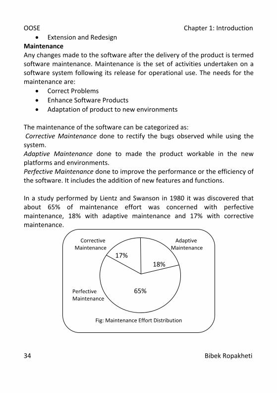
The maintenance of the software can be categorized as: Corrective Maintenance done to rectify the bugs observed while using the system. Adaptive Maintenance done to made the product workable in the new platforms and environments. Perfective Maintenance done to improve the performance or the efficiency of the software. It includes the addition of new features and functions. In a study performed by Lientz and Swanson in 1980 it was discovered that about 65% of maintenance effort was concerned with perfective maintenance, 18% with adaptive maintenance and 17% with corrective maintenance.
Corrective Adaptive Maintenance Maintenance
Perfective Maintenance
Fig: Maintenance Effort Distribution
17% 18%
65%
OOSE Chapter 1: Introduction
35 Bibek Ropakheti
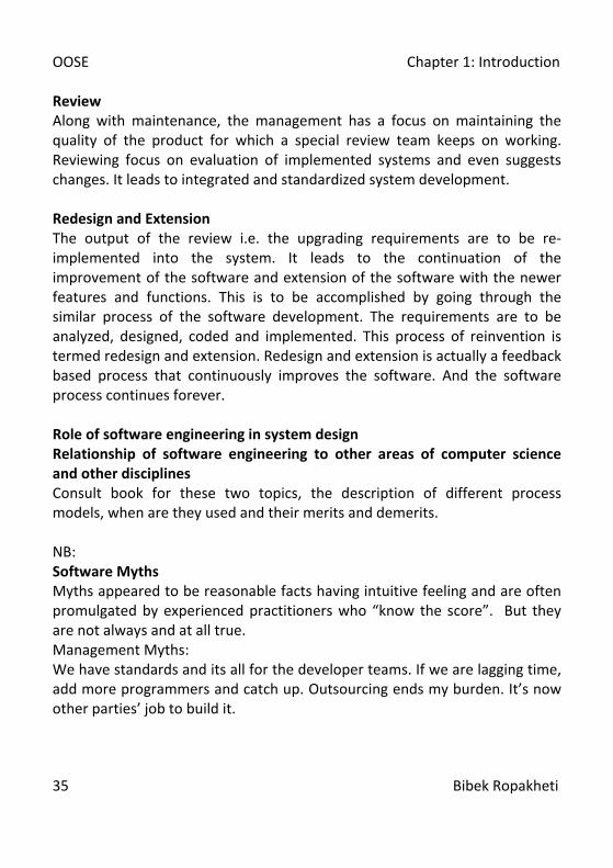
Review Along with maintenance, the management has a focus on maintaining the quality of the product for which a special review team keeps on working. Reviewing focus on evaluation of implemented systems and even suggests changes. It leads to integrated and standardized system development. Redesign and Extension The output of the review i.e. the upgrading requirements are to be re-implemented into the system. It leads to the continuation of the improvement of the software and extension of the software with the newer features and functions. This is to be accomplished by going through the similar process of the software development. The requirements are to be analyzed, designed, coded and implemented. This process of reinvention is termed redesign and extension. Redesign and extension is actually a feedback based process that continuously improves the software. And the software process continues forever. Role of software engineering in system design Relationship of software engineering to other areas of computer science and other disciplines Consult book for these two topics, the description of different process models, when are they used and their merits and demerits. NB: Software Myths Myths appeared to be reasonable facts having intuitive feeling and are often promulgated by experienced practitioners who “know the score”. But they are not always and at all true. Management Myths: We have standards and its all for the developer teams. If we are lagging time, add more programmers and catch up. Outsourcing ends my burden. It’s now other parties’ job to build it.
OOSE Chapter 1: Introduction
36 Bibek Ropakheti
Customer’s Myths: A general statement of objective is enough to begin writhing programs. Details can be filled later. Project requirements continuously change, software is flexible so, we can accommodate later. Practitioners Myths: One program is over and it works, our job is done. During development, no need of assessing the quality. The working product is just the required outcome and it makes project successful. SE will make unnecessary documents and waste our time. Some other points: Software is not manufactured, it is engineered. Software does not wear out [But yeah, it timeout]. Software industry is moving towards component-based construction, but what about software? No it is yet custom built. References:
1. R.S Pressman, Software Engineering: A Practitioner’s Approach, 5/e, Mc Graw Hill International Edition
2. C.Ghezzi, M. Jazayeri and D. Mandrioli, Fundaments of Software Engineering prentice Hall of India, Ltd.
3. R. Fairly, Software Engineering, Mc Graw Hill Publishing Co. 4. Igor Hawryszkiewycz, Introduction to System Analysis and Design,4/e,
Prentice Hall of India Private Limited 5. R. Mall, Foundations of Software Engineering.

OOSE Chapter 2: Project Management Concepts
37 Bibek Ropakheti
Chapter 2 Project Management Concepts The Management Spectrum Effective Software Project Management focuses on four Ps:
• People • Process
• Product • Project
PEOPLE All people involve in software development directly or indirectly. They are: Stake Holders:
• Senior Managers: Business issues • Project Managers: plan, motivate, organize, and control others. • Practitioners: Technical persons • Customers: Specify requirements and interested in outcome. • End Users: Interact with software
Team Leader: Team Leaders are the leading practitioners and their general traits are: • Motivation • Organization • Ideas or Innovation • Problems Solving • Managerial Identity
• Achievement • Influence • Team Building • Co-ordination
Software Team: It depends on the management style of an organization.
Project factors while planning or structuring a team. • Difficulty of problem to be solved • Size of program code • Team lifetime • Degree of modularization of problem • Quality and Reliability requirement of the product • Time constrain • Sociability / communication between the team required.
OOSE Chapter 2: Project Management Concepts
38 Bibek Ropakheti
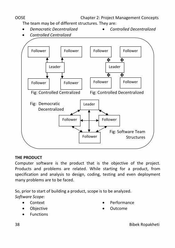
The team may be of different structures. They are: • Democratic Decentralized • Controlled Decentralized • Controlled Centralized
THE PRODUCT Computer software is the product that is the objective of the project. Products and problems are related. While starting for a product, from specification and analysis to design, coding, testing and even deployment many problems are to be faced. So, prior to start of building a product, scope is to be analyzed. Software Scope:
• Context • Objective • Functions
• Performance • Outcome
Fig: Controlled Centralized Fig: Controlled Decentralized Fig: Democratic Decentralized
Fig: Software Team Structures
Leader
Follower
Follower
Follower
Follower
Leader
Follower Follower
Follower Follower
Leader
Follower Follower
Follower
OOSE Chapter 2: Project Management Concepts
39 Bibek Ropakheti
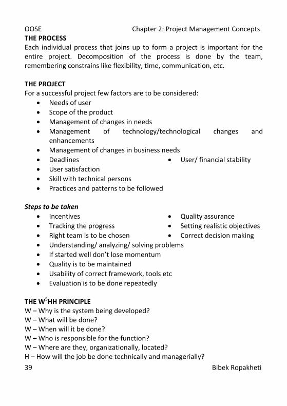
THE PROCESS Each individual process that joins up to form a project is important for the entire project. Decomposition of the process is done by the team, remembering constrains like flexibility, time, communication, etc. THE PROJECT For a successful project few factors are to be considered:
• Needs of user • Scope of the product • Management of changes in needs • Management of technology/technological changes and
enhancements • Management of changes in business needs • Deadlines • User satisfaction
• User/ financial stability
• Skill with technical persons • Practices and patterns to be followed
Steps to be taken
• Incentives • Quality assurance • Tracking the progress • Setting realistic objectives • Right team is to be chosen • Correct decision making • Understanding/ analyzing/ solving problems • If started well don’t lose momentum • Quality is to be maintained • Usability of correct framework, tools etc • Evaluation is to be done repeatedly
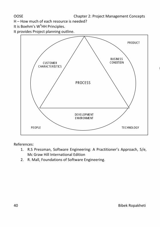
THE W5HH PRINCIPLE W – Why is the system being developed? W – What will be done? W – When will it be done? W – Who is responsible for the function? W – Where are they, organizationally, located? H – How will the job be done technically and managerially?
OOSE Chapter 2: Project Management Concepts
40 Bibek Ropakheti
H – How much of each resource is needed? It is Boehm’s W5HH Principles. It provides Project planning outline. References:
1. R.S Pressman, Software Engineering: A Practitioner’s Approach, 5/e, Mc Graw Hill International Edition
2. R. Mall, Foundations of Software Engineering.
PROPROCESS
PROCESS
CUSTOMER CHARACTERISTICS
BUSINESS CONDITION
DEVELOPMENT ENVIRONMENT
TECHNOLOGY PEOPLE
PRODUCT
PROJECT

OOSE Chapter 3: Project Planning
41 Bibek Ropakheti
Chapter 3 Project Planning Software scope Feasibility Resources
Human Reusable software Environment
Project Estimation The make/buy decision Outsourcing Project scheduling tracking Consult Notes provided at the class for software scope and feasibilities and, Consult Software Engineering: A Practitioner’s Approach by Roger S. Pressman for this chapter. References:
1. Igor Hawryszkiewycz, Introduction to System Analysis and Design,4/e, Prentice Hall of India Private Limited
2. R.S Pressman, Software Engineering: A Practitioner’s Approach, 5/e, Mc Graw Hill International Edition
3. R. Mall, Foundations of Software Engineering.

OOSE Chapter 4: Risk Analysis and Management
42 Bibek Ropakheti
Chapter 4 Risk Analysis and Management Software Risks Risk Identification Risk Projection Risk Refinement Risk Mitigation, Monitoring and Management Safety Risks and Hazards RISK MANAGEMENT STRATEGIES Risk involves changes in mind, opinion, actions or place. Risk concerns future happenings. Risk contains choice and the uncertainty and that the choice itself entails. Hence, risk is certain (like death and taxes) Robert Charette So, we need to identify risk. Risk analysis and management are a series of steps that help a software team to understand and manage uncertainty.
Risk Identification
Risk Analysis
Risk Planning
Risk Monitoring
List of Potential Risks
Prioritized Risk List
Risk Avoidance and Contingency Plan
Risk Assessments
OOSE Chapter 4: Risk Analysis and Management
43 Bibek Ropakheti
A risk is a potential problem that might happen or not. But it’s better to identify it, assess its probability of occurrence, estimate its impact and establish a contingency plan (when it will occur is determined or estimate in this plan) Steps:
• Risk Identification • Analysis Analyses
• Risk Ranking • Risk Management
REACTIVE RISK STRATEGY Reactive risks are also called “Indiana Jones School of Risk Management”. Similarly, to Indiana Jones facing risk after happening, software team also face problem and start solving it once it takes place. It is often called fire-fighting mode. Resources are set aside to deal them while analysis. If in this case problem could not be solve, crisis management takes over i.e. the project is in real jeopardy. PROACTIVE RISK STRATEGY It is a more intelligent strategy for risk management. A proactive strategy begins long before technical work is started. Plan is established for managing risk. Primary objective is to avoid risk, but all risks can’t be avoided, the team works to develop a plan to respond the risk in a controlled and effective manner. SOFTWARE RISKS Characteristics of risk:
• Uncertainty: Risk may or may not happen, so it’s uncertain. • Loss: If the risk becomes a reality, unwanted consequences or
losses will occur. When Risk is analyzed, it is a must to confirm the level of uncertainty and degree of loss associated with each risk. For this, risks are categorized as, Project Risks: affect the project schedule or resources or cost. Product Risk or Technical Risks: affect the quality or performance or even implementation possibilities.

OOSE Chapter 4: Risk Analysis and Management
44 Bibek Ropakheti
Business Risks: affect the organization developing or procuring the software. Some business risks are: Market: business excellent product that no one wants. Strategic: product that doesn’t fit into business strategy. Sales: product that is next to impossible to sell. Management: losing management support due to focus / policy change Budget: losing budgetary or personal commitment Known Risks: easily uncover able risks. Predictable Risks: extrapolated from past project experience. Unpredictable Risks: May or may not occur and are extremely difficult to identify. RISK IDENTIFICATION Risk Identification is a systematic way of discovering or specifying the risks or threats. Generally, risks are of two types:
• Generic Potential threats to all software projects. • Product – specific Potential threats that may occur while
developing the specific software. Identifying the risk is through the checklists. Generic risks can be of following types:
• Product size • Business impact • Customer characteristics • Process definition • Development environment • Technology to be built • Staff size and experience
Checklist is prepared as a set of Components and driver of risks.
OOSE Chapter 4: Risk Analysis and Management
45 Bibek Ropakheti
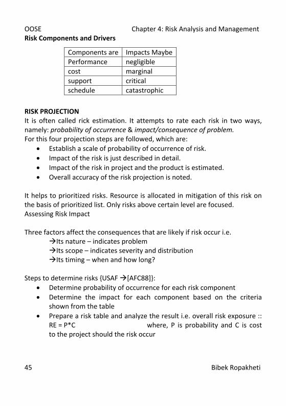
Risk Components and Drivers RISK PROJECTION It is often called rick estimation. It attempts to rate each risk in two ways, namely: probability of occurrence & impact/consequence of problem. For this four projection steps are followed, which are:
• Establish a scale of probability of occurrence of risk. • Impact of the risk is just described in detail. • Impact of the risk in project and the product is estimated. • Overall accuracy of the risk projection is noted.
It helps to prioritized risks. Resource is allocated in mitigation of this risk on the basis of prioritized list. Only risks above certain level are focused. Assessing Risk Impact Three factors affect the consequences that are likely if risk occur i.e.
Its nature – indicates problem Its scope – indicates severity and distribution Its timing – when and how long?
Steps to determine risks {USAF [AFC88]}:
• Determine probability of occurrence for each risk component • Determine the impact for each component based on the criteria
shown from the table • Prepare a risk table and analyze the result i.e. overall risk exposure ::
RE = P*C where, P is probability and C is cost to the project should the risk occur
Components are Impacts Maybe Performance negligible cost marginal support critical schedule catastrophic

OOSE Chapter 4: Risk Analysis and Management
46 Bibek Ropakheti
Ex: Find RE, if Risk Chance = 70%, Risk probability = 80% (assume), Risk Impact60 components were there i.e. 70% of 60 = 42, so, 18 components to be built. If components 100 LOC and LOC cost Rs 100, Then overall cost = 18*100*100 = Rs 180000 Now, Risk Exposure (RE) = 80% of 180000 = Rs 144000 [Risk refinement; risk mitigation, monitoring and management i.e. RMMM and RMMM Plan]
For RMMM, RMMM Plan and Safety Risks & Hazards, Consult Software Engineering: A Practitioner’s Approach by Roger S. Pressman. References:
1. R.S Pressman, Software Engineering: A Practitioner’s Approach, 5/e, Mc Graw Hill International Edition
2. R. Mall, Foundations of Software Engineering. 3. Igor Hawryszkiewycz, Introduction to System Analysis and Design,4/e,
Prentice Hall of India Private Limited
OOSE Chapter 5: Software Quality
47 Bibek Ropakheti
Chapter 5 Software Qualities Classification of Software Qualities Representative Qualities or Quality Factors Quality Requirements Based On Application Areas Quality Concepts Software Quality Assurance Software Reviews Formal Technical Reviews Software Reliability Software Configuration Management SCM Standards For Classification of software qualities, Representative qualities, Quality requirements based on application areas, consult Fundaments of Software Engineering by C.Ghezzi, M. Jazayeri and D. Mandrioli and class notes. Quality Concepts According to American heritage dictionary, quality is the characteristics or attributes of something. But above all it must have some standards. The quality is often used to describe our goal of producing error free systems that meet the user requirements with minimum effort. But defining quality as the delivery of the best product won’t be sufficient. In today’s world the process of development should also be following the standard in order to maintain the quality. For this, quality is broadly categorized as: Quality of Conformance: It is the characteristics of the system by which the conformity of design specifications being strictly followed during constructions are assessed. It focuses on implementation of the system. It is often termed as external quality or product quality. Quality of Design: It is the characteristics of the system specified by the designers. It encompasses requirements specifications and design of the system. It is often called internal quality or process quality.
OOSE Chapter 5: Software Quality
48 Bibek Ropakheti
Robert Glass described that user satisfaction is the major factor for the quality. He gave an equation to describe user satisfaction: User Satisfaction=
Compliant Product + Good Quality + Delivery within Budget and Schedule
DeMarco defined quality as a function of how much it changes the world for the better. To sum up let us take the definition of software quality given by R.S. Pressman that: Conformance to explicitly stated functional and performance requirements, explicitly documented development standards, and implicit characteristics that are expected of all professionally developed software is software quality. Actually, variation is the heart of any system so is variation control that of quality control. Hence, variations or deviations among the products must be minimized and it is maintaining quality. Quality Control is the controlling of variation to the standards. Quality control involves series of inspections, reviews and tests used throughout the software process to ensure each work product meets requirements placed upon it. Quality control includes a feedback loop to the process that created the work product. A key concept of quality control is that all work products have defined, measurable specifications to which we may compare the output of each process. The feedback loop is essential to minimize the defects produced. Software Quality Factors The modern view of quality associates a software product with several quality factors such as:
• Portability • Usability • Reusability • Correctness • Robustness
• Reliability • Maintainability • Dependability • Efficiency • Integrity

OOSE Chapter 5: Software Quality
49 Bibek Ropakheti
• Performance • Verifiability • Evolvability • Interoperability • Productivity
• Timeliness • Visibility • Understandability • Malleability, etc.
Software Quality Assurance Software quality assurance is planned and systematic activities that are required to ensure high quality in software. When it comes to software the process of ensuring the quality of the software as well as the quality of the software development standards is SQA. Software lacks quality if:
• Requirement lacks quality or completeness • Software development standards are not maintained • Requirements are not fulfilled
Hence, activities done to insure the aforementioned quality requirements are the part of software quality assurance. In past, for hardware development quality control and quality assurance was used to be done by the craftsman himself. First time in 1916 at Bell lab, QA and QC was separately done in the hardware developments. In software development, during 1960s, quality was the sole responsibility of the programmer. In military contracted software development, during 1970s, concept of SQA and SQC was developed and employed. Then the special SQA personals were started to get involved in software development. Even then all the peoples involved in the development process are equally responsible for the perpetuation of the quality. SQA Activities SQA is composed of a variety of tasks associated with the software engineers who perform the technical work and an SQA group that has the responsibility for quality assurance planning, oversight, record keeping, analysis, and reporting.

OOSE Chapter 5: Software Quality
50 Bibek Ropakheti
Software engineers address quality by applying solid technical methods and measures, conducting formal technical reviews, and performing well planned software testing. The SQA groups assist the software team in achieving a high quality end product. For that they have to perform some special SQA activities as follows: Prepares an SQA plan for a project i.e. planning Participate in the development of the project’s software process description i.e. oversight Reviews software engineering activities to verify the compliance with the defined software process i.e. review Audits designated software work products to verify compliance with those defined as a part of the software process i.e. investigate Ensures that deviations in software work and work products are documented and handled according to a documented procedure i.e. analysis Records any noncompliance i.e. record keeping Reports to senior management i.e. reporting Software Reviews Reviewing the software is the process of filtering of low quality components. The reviews are applied at the different points during the software development which helps in the detection of errors and defects. Freedman and Weinberg related technical work and review to the pencil and eraser. They described that the errors are made even by the experts and the review done by somebody else is more probable to detect the errors compared to the reviews done by them. Reviews can be done in many ways like an informal meeting, seminar, presentation, conference, walkthrough, inspection etc. Other than these a modified approach is also used called formal technical review. We will discuss it later. Cost Impact of Software Defects Software reviews are done in order to find the errors during the process that may become defects on release of the software. As the cost of errors increase with the phases of software development, reviews help in the removal of such errors and expenses raised from those errors. Cost of the software errors and their removal is shown in the chart below.

OOSE Chapter 5: Software Quality
51 Bibek Ropakheti
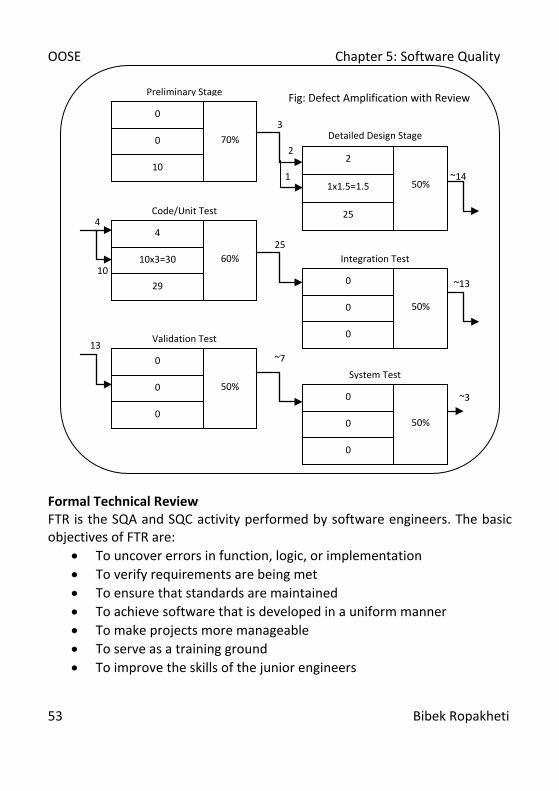
It can be concluded that the presence of defects increase the cost of the software. And the cost of removal of defects increases with time i.e. cost of removal of the error increases as the phase of the detection and removal of the error delays. It has been shown by the studies that the design activities introduce maximum i.e. 50 to 60 % of all errors during the software development life cycle. Software reviews help to alleviate the errors introduced. Among software review techniques FTR has been the most successful one that detects 75% errors. Defect Amplification and Removal As an error remains undetected at one phase of software development, the loss that may occur due to the error gets amplified. This process of defect amplification has been modeled by IBM and is called defect amplification model. It illustrates the generation and detection of errors during the different phases of software engineering process.
Fig: Relative Cost of Correcting an Error
1
10
100
1000
Comm. Code System Testing
1
610
4070
1000
Relative Cost of Correcting
an Error
Phase

OOSE Chapter 5: Software Quality
52 Bibek Ropakheti
Fig: Defect Amplification without Review
10
6
4 37
10
120 27
60 60
30
15
System Test
0
0
0
50%
Integration Test
0
0
0
50%
Code/Unit Test
10
29
27x3=81
20%
Validation Test
0
0
0
50%
Detailed Design Stage
6
25
4x1.5=6
0%
Preliminary Stage
0
10
0
0%
Development Defects Detection
Errors From Previous Steps
Errors Passed
To Next Step
Fig: Defect Amplification Model
Errors Passes through
Newly Generated Errors
Amplified Errors 1: x
Percent
Efficiency for Error
Detection
OOSE Chapter 5: Software Quality
53 Bibek Ropakheti
Formal Technical Review FTR is the SQA and SQC activity performed by software engineers. The basic objectives of FTR are:
• To uncover errors in function, logic, or implementation • To verify requirements are being met • To ensure that standards are maintained • To achieve software that is developed in a uniform manner • To make projects more manageable • To serve as a training ground • To improve the skills of the junior engineers
Fig: Defect Amplification with Review
3
2
1 ~14
4
25 10
~13 13
~7
~3
System Test
0
0
0
50%
Integration Test
0
0
0
50%
Code/Unit Test
4
29
10x3=30
60%
Validation Test
0
0
0
50%
Detailed Design Stage
2
25
1x1.5=1.5
50%
Preliminary Stage
0
10
0
70%

OOSE Chapter 5: Software Quality
54 Bibek Ropakheti
The FTR is actually a class of reviews that includes walkthrough, inspections, round robin reviews, and other small group technical assessments of software. FTR is conducted as a meeting followed by above different classes of reviews. The Review Meeting As a FTR is never completed without review meeting, the review meeting is one of the most important parts of FTR. Before doing the review meeting planning should be done for the meeting. Review meetings need well preparation. While holding the meeting, 3-5 peoples are generally involved. To avoid lengthy meetings these well planning and preparation helps a lot. While reviewing the development phases, it should focus on small components rather than bigger components. Above all the review meetings should be short and sweet. General a review meeting is initiated by the producer whose work product is to be reviewed. He informs the project leader who then consults the review leader who evaluates the product for readiness and generates its multiple copies for the reviewers to review. Each reviewer reviews the work product, makes note and be familiar with the product. Concurrently, review leader prepares the agenda for the meeting. Then the meeting is held generally on the next day of preparation. One of the reviewers serves as a recorder who records all the proceedings of the review meeting. With the introduction to agenda, the meeting starts as a walkthrough and recorder keep all the information about errors and problems. By the end of the review, all attendees decide whether accept the product or reject it. They may also suggest conditional approvals. The FTR completes with the sign off by all the attendees, indicating their participation and their concurrence with the review team’s findings.

OOSE Chapter 5: Software Quality
55 Bibek Ropakheti
Review Reporting and Record Keeping FTR is always outputted with a report. All the issues are recorded at the end of review reporting. Review issues list is prepared at the end of FTR meeting. After the list preparation, the FTR summary report is prepared. The FTR report basically answers few questions:
• What was reviewed? • Who reviewed it? • What were the findings and conclusions?
The basic objectives of the review report is to identify problem areas within the product and serve as an action item checklist that guides the producer as corrections are made. Follow ups are the final procedure done to conclude the output of FTR. Review Guidelines An uncontrolled FTR can be worse than no review at all. While accomplishing reviews during FTR there are few guidelines to be followed as:
• Focus product while reviewing, not the producer • Set agenda, on which focus is always maintained • No debates while meeting • FTR is to enunciate problem areas, not solving it • Note down ideas • FTR meeting should not be over crowded • Use checklist for reviewing • Allocate enough time and resources for FTR • Conduct meaningful training for all the reviewers • Re-review the older ones • Being gentle to point out the errors is more fruitful
Formal Approaches to Software Quality Assurance Over the past few years, software engineering community has argued that SQA requires a more formal approach. It can be argued that a computer program is a mathematical object. Syntax and semantics can be defined for every programming language. And for that formal approaches for software requirements are also available. Generally they are:
• Proof of Correctness
OOSE Chapter 5: Software Quality
56 Bibek Ropakheti
• Statistical SQA • Clean Room Software Engineering
Proof of Correctness Proof of correctness focus the use of the technique of a formal logic system to prove that if the input values satisfy certain constraints, the output values produced by the program, satisfy certain properties. It basically focuses correctness of code. Statistical SQA Statistical software quality assurance is an SQA approach focusing industry to become more quantitative about quality. Statistical SQA implies the following steps:
• Collection of information about software defects is done. • Software defects are categorized. • Cause of each defects are traced. • Using Pareto principle, vital causes of errors are identified. • Move to correct these causes are taken.
Six sigma is the most widely used strategy for statistical quality assurance. It’s a rigorous and disciplined methodology that uses data and statistical analysis to measure and improve a company’s operational performance by identifying and eliminating defects in manufacturing and service related processes. Six sigma is accomplished using various five steps. Six sigma defines three core steps:
• Define: Define customer requirements, deliverables, and project goals as well as methods for customer communication.
• Measure: Measure the existing process and its output to determine current quality performance.
• Analyze: Analyze the defect metrics and determine the vital causes. For an organization that is improving the existing software, six sigma suggests two additional steps:

OOSE Chapter 5: Software Quality
57 Bibek Ropakheti
• Improve: Improve the process by eliminating the root causes of the defects.
• Control: Control the process for ensuring that future work does not reintroduce the causes of defects.
These set of activities is often referred as DMAIC method. For a new software development, six sigma suggests different sets of steps:
• Design: Design the process to meet customer requirements as well as avoid the root causes of defects.
• Verify: Verify the process model. These set of activities is often referred as DMADV method. Clean Room Software Engineering The integrated use of conventional software engineering modeling, program verification, and statistical quality assurance have been combined into a technique that can lead to extremely high quality software and is called clean room software engineering. It is an approach that emphasizes the need to build correctness into software as it is being developed. The philosophy behind clean room software engineering is to avoid dependence on costly defect removal processes by writing code increments right the first time and verifying their correctness before testing. Its process model incorporates the statistical quality certification of code increments as they accumulate into a system. The major tasks conducted as part of clean room software engineering are:
1. Increment planning 2. Requirement gathering 3. Box structure specification 4. Formal design 5. Correctness verification 6. Code generation, inspection, and verification 7. Statistical test planning 8. Statistical use testing 9. Certification
OOSE Chapter 5: Software Quality
58 Bibek Ropakheti
Software Quality Standards According to the IEEE Comp. Soc. Software Engineering Standards Committee a standard can be:
• An object or measure of comparison that defines or represents the magnitude of a unit
• A characterization that establishes allowable tolerances or constraints for categories of items,
• A degree or level of required excellence or attainment There are many standard organizations and they have their own quality standards. We will discuss two most used standards. ISO ISO is a consortium of 63 countries established to formulate and foster standardization. ISO published its 9000 series of standards in 1987. ISO 9000 is a series of three standards: ISO 9001, ISO 9002 and ISO 9003. ISO 9001 applies to the organizations engaged in development, design, production and servicing of goods. ISO 9002 applies to those organizations which do not design products but are involved in production, so not applicable for software developing organization. ISO 9003 applies to organizations involved only in installation and testing of the products. ISO standards are applicable to the organizations and not the products. Since above mentioned ISO standards do not address the software development in 1991 ISO 9000-3 document was released that address the software development standards for any organization. There are six steps of getting ISO certified:
• Application: Applying to a registrar for registration. • Pre-Assessment: The registrar makes a rough assessment of the
organization. • Document Review and Adequacy of Audit: The registrar reviews the
documents submitted by the organization and makes suggestions for possible improvements.
OOSE Chapter 5: Software Quality
59 Bibek Ropakheti
• Compliance Audit: The registrar checks whether the suggestions made by it during review have been compiled with by the organization or not.
• Registration: The registrar awards the ISO 9000 certificate after successful completion of all previous phases.
• Continued Surveillance: the registrar continues to monitor the organization, though periodically.
ISO certification has many benefits to the organization, like:
• Increment of confidence of customers in any organizations. • Helps in production of well documented software. • Helps in development of focused, efficient and cost effective product. • Helps in pointing out the weak points of an organization and
recommends remedial action. • Sets the basic framework for the development of an optimal process
and TQM. Summary of ISO 9001 Requirements can be found at “http://www.praxiom.com/iso-90003.htm”. The major shortcomings of ISO 9000 certification are:
• ISO 9000 requires a software production process to be adhered to but does not guarantee the process to be of high quality.
• ISO 9000 certification process is not foolproof. • ISO 9000 does not automatically lead to continuous process
improvement. • ISO 9000 does not confirm use of domain expertise so it may lag in
the skill factor. The basic features of ISO 9001 requirements are:
• Well managed documents. • Well planned development. • Checked and reviewed documents for effectiveness and correctness. • Testing against specification. • Reporting and few other organizational feedbacks. •

OOSE Chapter 5: Software Quality
60 Bibek Ropakheti
SEI/CMM Software Engineering Institute of Carnegie Mellon University, USA proposed a software standard called Capability Maturity Model. CMM is a reference model for inducting the software process maturity into different levels. It can be used to predict the most likely outcome to be expected from the next project that the organization undertakes. SEI CMM can be used in two ways: capability evaluation and software process assessment. Capability evaluation provides a way to assess the software process capability of an organization. It indicates the performance of the developing agency or contractor and helps in awarding the project to a contractor. Software process assessment is used by an organization to improve its process capabilities. SEI CMM classifies software development industries into the following five categories according to the maturity level. It is shown in the table below:
CMM Level Focus Key Process Area Initial Competent People Ad hoc Activities
Repeatable Project Management Software Project Planning,
SCM
Defined Definition of Processes Process Definition, Training Program,
Peer reviews
Managed Product and Process Quality
Quantitative Process Metrics, Software Quality Management
Optimizing Continuous Process
Improvement Defect Prevention,
Process Change Management, Technology Change Management

OOSE Chapter 5: Software Quality
61 Bibek Ropakheti
CMM just suggests what to do to improve the quality but does not suggest how to achieve it. Comparison of ISO 9000 Certification and SEI/CMM
• ISO 9000 is awarded by an international standards body, hence it can be quoted by an organization in their official documents or other places but CMM assessment is purely internal.
• SEI CMM was developed specially for software development so it addresses many issues that ISO does not.
• SEI CMM goes beyond quality assurance and prepares an organization to ultimately achieve TQM. While comparing, ISO aims at level 3 of SEI CMM.
• SEI CMM model provides a list of key process areas on which an organization at any maturity level needs to concentrate to take it from one maturity level to the next. Thus, it provides a way for achieving gradual quality improvement.
Further information on CMM and CMMI can be found at:
• http://www.sei.cmu.edu/cmm/ • http://www.sei.cmu.edu.u/cmmi/ • http://www.sei.cmu.edu/cmmi/
For SCM and SCM Standards, consult Software Engineering: A Practitioner’s Approach by Roger S. Pressman or Foundations of Software Engineering by Rajib Mall. References:
1. R.S Pressman, Software Engineering: A Practitioner’s Approach, 5/e, Mc Graw Hill International Edition
2. R. Mall, Foundations of Software Engineering. 3. Igor Hawryszkiewycz, Introduction to System Analysis and Design,4/e,
Prentice Hall of India Private Limited

OOSE Chapter 6: System Engineering Principles
62 Bibek Ropakheti
Chapter 6 System Engineering Principles Business Process Engineering Product Engineering Requirements Engineering
Requirements Elicitation Requirements Analysis and Negotiation Requirements Specification Requirements Validation Requirements Management
System Modeling (in detail) Data (ERD) Functional (DFD, CFD) Behavioral (STD)
For Business Process Engineering and Product Engineering, consult Software Engineering: A Practitioner’s Approach by Roger S. Pressman. Requirements Engineering Software requirements engineering is a process of discovery, refinement, modeling and specification. Initially, requirements are established then these requirements are refined in detail. Models of required data, information flow, control flow and operational behavior are established. Finally, alternative solutions are analyzed and a complete analysis model is created. Requirement engineering is the systematic use of proven principles, techniques languages and tools for cost effective analysis, documentation and on-going evolution of user needs and the specification of the external behavior of a system to satisfy those user needs. Both, the software engineer and user or customer are equally involved in software requirement engineering.
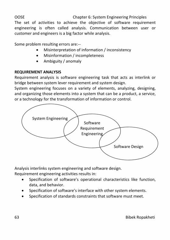
OOSE Chapter 6: System Engineering Principles
63 Bibek Ropakheti
The set of activities to achieve the objective of software requirement engineering is often called analysis. Communication between user or customer and engineers is a big factor while analysis. Some problem resulting errors are:--
• Misinterpretation of information / inconsistency • Misinformation / incompleteness • Ambiguity / anomaly
REQUIREMENT ANALYSIS Requirement analysis is software engineering task that acts as interlink or bridge between system lever requirement and system design. System engineering focuses on a variety of elements, analyzing, designing, and organizing those elements into a system that can be a product, a service, or a technology for the transformation of information or control.
Analysis interlinks system engineering and software design. Requirement engineering activities results in:
• Specification of software’s operational characteristics like function, data, and behavior.
• Specification of software’s interface with other system elements. • Specification of standards constraints that software must meet.
System Engineering
Software Requirement Engineering
Software Design
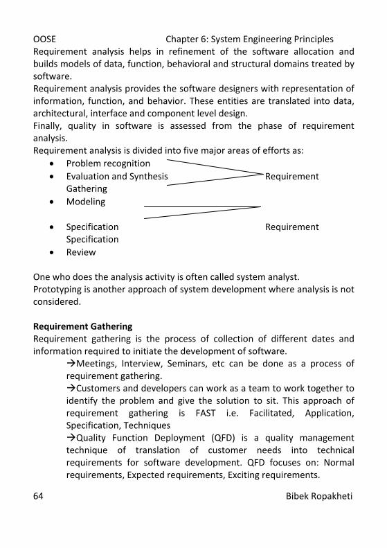
OOSE Chapter 6: System Engineering Principles
64 Bibek Ropakheti
Requirement analysis helps in refinement of the software allocation and builds models of data, function, behavioral and structural domains treated by software. Requirement analysis provides the software designers with representation of information, function, and behavior. These entities are translated into data, architectural, interface and component level design. Finally, quality in software is assessed from the phase of requirement analysis. Requirement analysis is divided into five major areas of efforts as:
• Problem recognition • Evaluation and Synthesis Requirement
Gathering • Modeling
• Specification Requirement
Specification • Review
One who does the analysis activity is often called system analyst. Prototyping is another approach of system development where analysis is not considered. Requirement Gathering Requirement gathering is the process of collection of different dates and information required to initiate the development of software.
Meetings, Interview, Seminars, etc can be done as a process of requirement gathering. Customers and developers can work as a team to work together to identify the problem and give the solution to sit. This approach of requirement gathering is FAST i.e. Facilitated, Application, Specification, Techniques Quality Function Deployment (QFD) is a quality management technique of translation of customer needs into technical requirements for software development. QFD focuses on: Normal requirements, Expected requirements, Exciting requirements.
OOSE Chapter 6: System Engineering Principles
65 Bibek Ropakheti
Use case scenario also helps a lot while translating user needs to technical specification.
NB: Often Requirements Engineering Process are categorized as –
• Feasibility Study • Requirement Gathering and Analysis • Requirement Specification • Requirement Validation • Requirement Management
ANALYSIS PRINCIPLES
There are many methods of analyzing the requirements. There principle or focus driven methods for analysis are analysis principles. Even though different, all the analysis principles are guided by some set of operational principles as—
• Representation and understanding the problem information • Objective and functions that the software need to fulfill • Behavior of the software is to be represented • The models should be partitioned in such a way that inner details
that are layered should me uncovered • The analysis should consider implementation of the information
as requirements. Davis gave additional 6 guiding principles:
• Understand the problem before you begin the analysis model • Develop a prototype that helps user to understand human-computer
interaction (it focuses on user friendliness). • Record the origin of and reason for every requirement • Use multiple views of requirements • Rank requirements • Work to eliminate ambiguity

OOSE Chapter 6: System Engineering Principles
66 Bibek Ropakheti
Information Domain All software applications can be collectively called data processing. It is because software is built to process data and to transform data from one form to another. Information content represents the individual data and control objects that constitute some larger collection of information transformed by software. Information domain consists of three views of data control, namely,
• Information Content and Relationship • Information Flow • Information Structure
Information flow represents the manner in which data / control change as each move through the system. Information structure represents the organization of various data and control items. Modeling To get better understanding of the working of the software and its requirements models are to be developed. In software development, representation of the information transforms, the function that transform the information and the behavior of the system as the transformation takes place is modeling. Analysis principles focus of modeling of function and behavior. Functional Model: software transforms information, and in order to perform transformation three functions i.e. input, processing and output is to be done on the information. While function modeling problem specific functions are focused. Firstly, context level model is developed. Then over a series of iterations, more and more functional details are explained. Ultimately all the system functionalities are represented. Behavioral Models: most software responds the events from outside world. This stimulus-response characteristic forms the base for behavioral model. A computer program always exists in some externally observable mode of behavior that is changed only when some events takes place called state. A
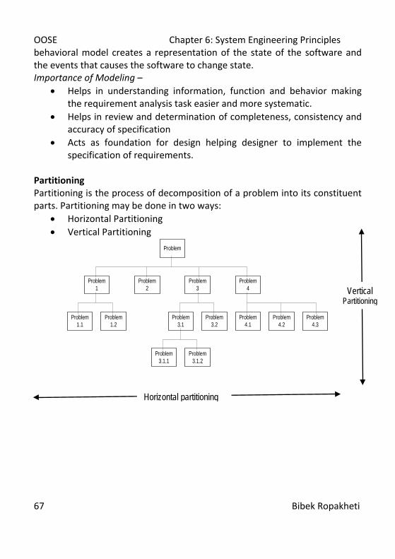
OOSE Chapter 6: System Engineering Principles
67 Bibek Ropakheti
behavioral model creates a representation of the state of the software and the events that causes the software to change state. Importance of Modeling –
• Helps in understanding information, function and behavior making the requirement analysis task easier and more systematic.
• Helps in review and determination of completeness, consistency and accuracy of specification
• Acts as foundation for design helping designer to implement the specification of requirements.
Partitioning Partitioning is the process of decomposition of a problem into its constituent parts. Partitioning may be done in two ways:
• Horizontal Partitioning • Vertical Partitioning
Problem
Problem 3.1.1
Problem 4.3
Problem 4.2
Problem 4.1
Problem 3.2
Problem 3.1
Problem 1.2
Problem 1.1
Problem 4
Problem 1
Problem 3
Problem 2
Problem 3.1.2
Vertical Partitioning
Horizontal partitioning

OOSE Chapter 6: System Engineering Principles
68 Bibek Ropakheti
Essentials and Implementation Views An essential view of software requirements presents the functions to be accomplished and information to be processed without regard to implementation details. The implementation views of software requirements present the real world manifestation of processing function and information structures. Essential view focuses on what to do? Implementation view focuses on how to do? SOFTWARE PROTOTYPING For any software development paradigm analysis is to be done, but the form may be different. Operational analysis principles may be applied and different models may be derived.
OR Requirement may be gathered, analyzed and then models may be derived or built for customer and developer assessment called prototyping. Prototyping may be: Closed Ended or Throwaway Prototyping—a prototype serves solely as a rough demonstration of requirements. It is then discarded, and the software is engineered using a different paradigm. Open Ended or Evolutionary Prototyping— it uses the prototype as the first part of an analysis activity that will be continued into design and construction. Customers are generally actively involved in development for getting feedback for the improvement of the software in prototyping. For effective prototyping, a prototype must be developed rapidly so that customer may assess results and recommended changes. For rapid prototyping, three generic classes of methods and tools are available as follows: Fourth Generation Technique – 4GT encompasses a broad array of database query and reporting languages, program and application generators, and other very high level non-procedural languages. 4GT enables engineers to generate executable code quickly hence ideal for rapid prototyping.
OOSE Chapter 6: System Engineering Principles
69 Bibek Ropakheti
Reusable Software Component—another approach focuses on use of existing components to built software. Entire or improved component or even off shelf component may be used to develop rapid prototypes software. Formal Specification and Prototyping Environment – Replacing natural language specification and prototyping languages and tools have been developed. The developers are even improving these tools in order to develop interactive environments. These environments will enable an analyst to interactively create language-base applications of a system of software and invoke automated tools that translate the language base specification into executable code. It would also enable customer to use the prototype executable code to refine formal requirements. REQUIREMENT SPECIFICATION Specification affects quality. Incomplete, inconsistent and misleading specification creates frustration and confusion in developers. There had been multiple principles for specification, Blazer and Goodman proposed –
• Separate functionality from implementation • Develop behavioral mode showing data and functional responses of a
system to various stimuli from the environment. • Establish the context in which software operates by specifying the
manner in which other. • Define the environment where system operates and how intertwined
collection of agents react to stimuli in this environment. • Create a cognitive model rather than design or implementation
model. Cognitive model focuses on how system is perceived by the environment.
• Specification must be complete and detail. • Establish the content and structure of a specification in a way that
will enable it to be amenable to change. These principles are the base for specification or representation of software requirements. Now there specifications are to be represented in a paper. While representing few guidelines are to be followed as: --
• Representation format and content must be problem relevant and specific.
OOSE Chapter 6: System Engineering Principles
70 Bibek Ropakheti
• Information within the specification must be nested or layered depending upon details.
• Diagrams and other notational forms should be restricted in number and consistent in use
• Representation should be revisable Software Requirements and specification SRS is produced at the end of analysis. It gives information description, functional description, system behavior, performance requirement, design constraints, validation criteria and other related information. SRS is started with introduction specifying goals and the objectives of the software. It clarifies what is the scope of the software. SRS is climaxed by Bibliography, appendix and other documentations. Some SRS are accompanied by an executable copy of software and preliminary user manual, where this manual presents the software as the black box. SPECIFICATION REVIEW A review of the SRS is conducted by both the software developer and the customers. Review should be done carefully as specification forms are the foundation of software development. Review is started by examining completeness, consistency and accuracy of overall information, functional and behavioral domain. Review is continued in more detail in every domain vertically. Once review is completed SRS is signed off and transformed into a contract. Post requirements changes by customer may change the cost which is to be considered later. During review, SRS may face changes and it should be considered and addressed positively. CASE tool helps in review and changes. ANALYSIS MODELING SE begins with a series of modeling tasks that led to a complete specification of requirements and a comprehensive design representation for the software to be built. The analysis model is the first technical representation of a system. It is a set of different models.

OOSE Chapter 6: System Engineering Principles
71 Bibek Ropakheti
The analysis model is the first technical representation of a system. It is a set of different models. Over the time many models have been developed for the analysis. But two most used models are:--
• Structural analysis and • Object Oriented analysis
Few others are:-- • Data Structure System Development (DSSD) • Jackson System Development (JSD) • Structured Analysis and Design Technique (SADT)
Analysis modeling is basically focused on data and flow modeling. STRUCTURED ANALYSIS It is one of a classical modeling method. It is most probably most used modeling technique. It is a model building activity. Structured analysis considers data and the processes that transform the data as separate entities. Data objects are modeled in a way that defines their attributes and relationship. Processes that manipulate data objects are modeled in a manner that shows how they transform data as data objects flow through the system. Structured analysis used different graphical symbols/notations to model the system. THE ELEMENTS OF THE ANALYSIS MODEL Primary objectives of analysis model are –
• To describe what the customer required • To establish a basis for the creation of a software design • To define a set of requirements that can be validated once the
software is built For achievement of these objectives, the structure of the analysis model must be as shown in the figure below:

OOSE Chapter 6: System Engineering Principles
72 Bibek Ropakheti
Data—a repository that contains description of all data objects consumed or produces by the software. ERD—it shows the relationships between data objects. It is used to conduct the data modeling activity. DFD—DFD provides an indication of how data are transformed as they move to the system and to depict the functions that transform the data flow. DFD helps in analysis of information domain and serves as base for modeling of function, Process specification contains DFD. STD—STD indicates how the system behaves as a consequence of external events. STD represents the various modes of behavior and the manner in
(Data Modeling) (Functional Modeling) Data Object Process Description Specification
E-R Diagram DFD
Data Dictionary
State Transition Diagram
Control Specification (Behavioral Modeling)
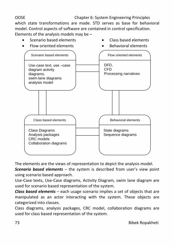
OOSE Chapter 6: System Engineering Principles
73 Bibek Ropakheti
which state transformations are made. STD serves as base for behavioral model. Control aspects of software are contained in control specification. Elements of the analysis models may be –
• Scenario based elements • Flow oriented elements
• Class based elements • Behavioral elements
The elements are the views of representation to depict the analysis model. Scenario based elements – the system is described from user’s view point using scenario based approach. Use-Case texts, Use-Case diagrams, Activity Diagram, swim lane diagram are used for scenario based representation of the system. Class based elements – each usage scenario implies a set of objects that are manipulated as an actor interacting with the system. These objects are categorized into classes. Class diagrams, analysis packages, CRC model, collaboration diagrams are used for class based representation of the system.
Scenario based elements
Use-case text, use –case diagram activity diagrams, swim-lane diagrams analysis model
Behavioral elements
State diagrams Sequence diagrams
Class based elements
Class Diagrams Analysis packages CRC models Collaboration diagrams
Flow oriented elements
DFD, CFD Processing narratives

OOSE Chapter 6: System Engineering Principles
74 Bibek Ropakheti
Behavioral elements – Behavioral or state transformation are traced in behavioral elements. Analysis model must provide modeling elements that depicts behavior. State and Sequence diagrams are used for representation of behavioral elements in the system. Flow oriented model – Information and control flows as the system is realized. These data, information and control elements are flow elements. DFDs, CFDs and Processing narratives are used to represent flow elements of the system. DATA MODELLING Analysis modeling begins with data modeling. Data modeling helps in defining data objects, and the relationship between data object and other information pertinent to the relationships. Data Objects – data objects are representation of almost any composite information that must be understood by software, where composite information is something that has different properties and attributes. A data object can be an external entity, a thing, an occurrence or event, a role, an organizational unit, a place or a structure. [Anything that performs something, some action, some responsibility, department, office/field etc., file etc.] Attributes – attributes defines the properties of a data object and take on one of three different characteristics, namely
• Name an instance of the data object • Describe the instance • Make reference to another instance of the data object
Relationship – data objects are connected to one another in different ways is relationship between them. It is important to note that object/relationship pairs are bi-directional, i.e. they can be read in either way. Cardinality – cardinality defines the maximum number of objects that can participate in a relationship. Modality – modality defines the compulsion of any object that affects the occurrence of another one. ‘0’ implies no explicit need of entity for the occurrence of relationship and ‘1’ implies mandatory need of entity for the relationship occurrence.

OOSE Chapter 6: System Engineering Principles
75 Bibek Ropakheti
E-R Diagram Data modeling is done using E-R Diagram. FUNCTIONAL MODELLING AND INFORMATION FLOW Information is transformed as it flows through a computer-based system. The system takes input in different forma as hardware, software and even human elements to transform information and produce output. The flow of information as input, from transformation to output can be tracked and modeled called flow model. Structured analysis actually begins as an information flow modeling technique. Functional modeling and information flow of a system can be represented using Data Flow Diagrams. Data Flow Diagrams A DFD is a graphical representation that depicts the information flow and the transforms that are applied as data move from input to output. A DFD reveals relationships among and between the various components in a program or system. A DFD is an important technique for modeling a system’s high level detail by showing how input data is transformed into output data through a sequence of functional transformations. DFD contains four major components as:
• External Entity: External entities or terminals are the source or the destination of data. These represent the entities outside the context of the system. These external entities provide data to the system or receive data from it. Entities are often represented as rectangles (a diagonal line across the right-hand corner means that this entity is represented somewhere else in the DFD). Entities are also referred to as agents, terminators, or source/sink.
• Function or Process: The process is the manipulation or work that transforms the data performing computations, making decisions or directing data flows based on business rules. Simply, process receives some input and generates some outputs. Process names (simple verbs and dataflow names, such as “Submit Payment” or “Get
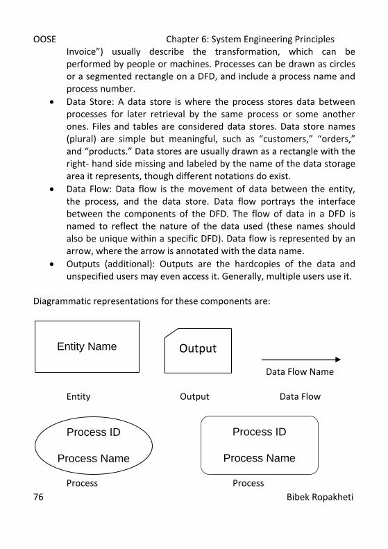
OOSE Chapter 6: System Engineering Principles
76 Bibek Ropakheti
Invoice”) usually describe the transformation, which can be performed by people or machines. Processes can be drawn as circles or a segmented rectangle on a DFD, and include a process name and process number.
• Data Store: A data store is where the process stores data between processes for later retrieval by the same process or some another ones. Files and tables are considered data stores. Data store names (plural) are simple but meaningful, such as “customers,” “orders,” and “products.” Data stores are usually drawn as a rectangle with the right- hand side missing and labeled by the name of the data storage area it represents, though different notations do exist.
• Data Flow: Data flow is the movement of data between the entity, the process, and the data store. Data flow portrays the interface between the components of the DFD. The flow of data in a DFD is named to reflect the nature of the data used (these names should also be unique within a specific DFD). Data flow is represented by an arrow, where the arrow is annotated with the data name.
• Outputs (additional): Outputs are the hardcopies of the data and unspecified users may even access it. Generally, multiple users use it.
Diagrammatic representations for these components are:
Entity Name
Data Flow Name Entity Output Data Flow
Process ID
Process Name
Process ID
Process Name
Process Process
Output
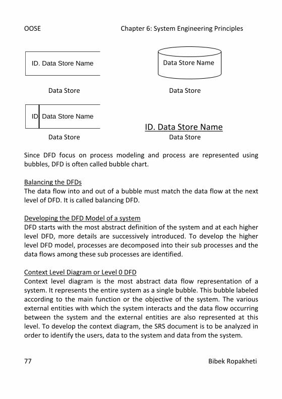
OOSE Chapter 6: System Engineering Principles
77 Bibek Ropakheti
ID. Data Store Name
Data Store Data Store
ID. Data Store Name
ID. Data Store Name Data Store Data Store Since DFD focus on process modeling and process are represented using bubbles, DFD is often called bubble chart. Balancing the DFDs The data flow into and out of a bubble must match the data flow at the next level of DFD. It is called balancing DFD. Developing the DFD Model of a system DFD starts with the most abstract definition of the system and at each higher level DFD, more details are successively introduced. To develop the higher level DFD model, processes are decomposed into their sub processes and the data flows among these sub processes are identified. Context Level Diagram or Level 0 DFD Context level diagram is the most abstract data flow representation of a system. It represents the entire system as a single bubble. This bubble labeled according to the main function or the objective of the system. The various external entities with which the system interacts and the data flow occurring between the system and the external entities are also represented at this level. To develop the context diagram, the SRS document is to be analyzed in order to identify the users, data to the system and data from the system.
Data Store Name
OOSE Chapter 6: System Engineering Principles
78 Bibek Ropakheti
Top-level DFD or Level 1 DFD Level 1 DFD examine the high level functional requirement. Generally 5 to 7 processes are used to decompose the context of the problem. If more functions are to be developed then related ones are to be combined as one and again be decomposed in the next level diagram and so on. Generally, external entities are not shown other than in context diagram. ID and naming are done using special conventions. At level 0, the process id is given 0. In the next level, 1, 2, 3…… n or 0.1, 0.2, 0.3…….. 0.n and so on during preceding levels. Data dictionary are also tagged along with the DFD.
• Completeness Few Quality Guidelines for DFD
• Consistency • Time considerations
• Iterative nature • Drawing primitives
• Black holes Some common errors in DFDs
• Miracles • Complexity (not > 7) • Unlabelled Components
• Data flow without process • Data store as source or sink • Expectation of perfect DFD at the first attempt
Data Dictionary The data dictionary is an organized listing of all the data elements that are pertinent to the system, with precise and rigorous definitions so that both analyst and the customer will have a common understanding of inputs, outputs, components of stores and even intermediate calculations. There have been different formats of data dictionary but generally all the conventions hold the information about: Name of the data Alias or other names for same data Where used and how i.e. in which processes this data has been used and how Content description giving notation for representing content and little other related information

OOSE Chapter 6: System Engineering Principles
79 Bibek Ropakheti
General notations are: = : composed of or equivalent to + : and [ , , ] [ | | ] : either or selection
{ }n : n times repetition ( ) : optional data *….* /……../: comments
Example: for address component Name: address Aliases: per_add, home_add Used where and how: address_of_student (input), student_address (output) Description: address=[street_num+street_name+district] street_num=int=/an integer number/ street_name=[char*|char[]]=*string* district=[char*,char[]] For Behavioral Modeling, consult Software Engineering: A Practitioner’s Approach by Roger S. Pressman. References:
1. R.S Pressman, Software Engineering: A Practitioner’s Approach, 5/e, Mc Graw Hill International Edition
2. R. Mall, Foundations of Software Engineering. 3. Igor Hawryszkiewycz, Introduction to System Analysis and Design,4/e,
Prentice Hall of India Private Limited
OOSE Chapter 8: Object Oriented Fundamentals
80 Bibek Ropakheti
Chapter 7 Software Testing Software Testing Fundamentals Importance of Testing Test Case Design White Box Testing Black Box Testing Unit Testing Integration Testing Validation Testing System Testing Verifying and Debugging Symbolic Execution Software Testing Fundamentals Once source code has been generated, software must be tested to uncover as many errors as possible before final delivery to the customer. Testing is the unavoidable part of any responsible effort to develop a software system. When we say testing, it basically focuses the effort we apply on removal of bugs from the source code. But, high quality software cannot be achieved through testing of source code alone. Test cases are used for testing. The major goal of testing is to design a series of test cases that have a high probability of detecting the bugs. It can be said that the number of the bugs remaining in software is proportional to the number of bugs discovered. This is because one has most confidence in programs with no detected bugs and no confidence in programs with a long history of bug fixes. The best way of removal of defects from software is to detect and remove it during analysis and design. Software techniques provide systematic guidance for designing tests that exercise the internal logic of software components and exercise the input and output domain of the program to uncover the errors in program function, behavior and performance.
OOSE Chapter 8: Object Oriented Fundamentals
81 Bibek Ropakheti
Software testing is a critical element of SQA and represents the ultimate reviews of specification, design and code generation. Software engineer perform testing in early stage. As the testing process progresses, testing specialists are involved, but they are not sufficient. Every time the program executes, the customers test it. In fact, testing is one step in the software process that could be viewed as destructive rather than constructive. Importance of Testing Testing is the process of finding errors so the most important cause of testing is to find the errors and make the software accurate, complete and efficient. For more on the Importance of Testing, consult Software Engineering: A Practitioner’s Approach by Roger S. Pressman. Test Case Design Testing design is as challenging as software design. There are many test case design methods those have evolved for software. These methods provide the developer with a systematic approach to testing. These methods provide a mechanism that can help to ensure the completeness of tests and provide the highest likelihood for uncovering errors in the software. Testing can be done in one of the two ways:
Black Box Testing: knowing the specified functions that a product has been designed to perform, tests can be conducted that demonstrate each function is fully operational while at the same time searching for the errors in each one.
White Box Testing: knowing the internal working of a product, tests can be conducted to ensure that everything is well.
White Box Testing White box testing or glass box testing is a test case design method that uses the control structure of the procedural design to derive test cases that:

OOSE Chapter 8: Object Oriented Fundamentals
82 Bibek Ropakheti
• Guarantee that all independent paths within a module have been exercised at least once.
• Exercise all logical decisions on their true and false sides. • Execute all the loops at their boundaries and within their operational
bounds. • Exercise internal data structures to ensure their validity.
White box testing of software is predicted on close examination of procedural detail. Logical paths through the software are tested by providing test cases that exercise specific set of conditions and for loops. The status of the program may be examined at various points to determine if the expected or asserted status corresponds to the actual status. Even though, it seems that white box testing would eliminate all the errors, but due to large number of logical paths to be tested, it is impractical. So, few major logical paths are to be focused while testing. Also few important data structures can be probed for validity. Few of the defects addressed by white box testing are:
• Logical errors and incorrect assumptions. • We often believe that a logical path is not likely to be followed, but in
reality it is. • Typographical errors.
There are different white box testing techniques. Basis path testing is one among them. This method enables designer to derive a logical complexity measure to define a basis set of execution path. Test cases derived to exercise the basis set are guaranteed to execute every statement in the program at least once during testing. Using flow graphs, basis path are represented. For details on Basis Path Testing, Cyclomatic Complexity, Control Structure Testing, Condition Testing, Data Flow Testing, Loop Testing and Mutation Testing, Consult Software Engineering: A Practitioner’s Approach, by Roger S. Presssman or, Foundations of Software Engineering by Rajib Mall.
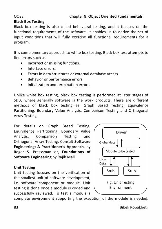
OOSE Chapter 8: Object Oriented Fundamentals
83 Bibek Ropakheti
Black Box Testing Black box testing is also called behavioral testing, and it focuses on the functional requirements of the software. It enables us to derive the set of input conditions that will fully exercise all functional requirements for a program. It is complementary approach to white box testing. Black box test attempts to find errors such as:
• Incorrect or missing functions. • Interface errors. • Errors in data structures or external database access. • Behavior or performance errors. • Initialization and termination errors.
Unlike white box testing, black box testing is performed at later stages of SDLC where generally software is the work products. There are different methods of black box testing as: Graph Based Testing, Equivalence Partitioning, Boundary Value Analysis, Comparison Testing and Orthogonal Array Testing. For details on Graph Based Testing, Equivalence Partitioning, Boundary Value Analysis, Comparison Testing and Orthogonal Array Testing, Consult Software Engineering: A Practitioner’s Approach, by Roger S. Presssman or, Foundations of Software Engineering by Rajib Mall. Unit Testing Unit testing focuses on the verification of the smallest unit of software development, i.e. software component or module. Unit testing is done once a module is coded and successfully reviewed. To test a module a complete environment supporting the execution of the module is needed.
Global data Local Data
Fig: Unit Testing Environment
Driver
Module to be tested
Stub Stub
OOSE Chapter 8: Object Oriented Fundamentals
84 Bibek Ropakheti
These subsidiary codes are called a stub or a driver. A driver is generally a main program that accepts test case data, passes such data to the component, and prints relevant results. A stub or dummy subprogram uses the subordinate module’s interface, may do minimal data manipulation, provides verification of entry, and returns control to the module undergoing testing. Integration Testing Integration testing is a systematic technique for constructing the software architecture while at the same time conducting tests to uncover errors associated with interfacing. The primary objective of integration testing is to test the module interfaces in order to ensure that there are no errors in the parameter passing, when one module invokes another module. While integrating different approaches can be used for integrating as well as testing. The general approaches are: Big Bang Integration Testing: All the modules of the system are simply put together and tested. Top down Integration Testing: Top down integration starts with the main routine and one or two subordinate routines in the system. With the use of stubs, when integration is done, testing is also accomplished. Bottom up Integration Testing: Similar to the top down integration, it differs in the context that the subordinate routines are first integrated and tested. Other approaches are Mixed Integration Testing, Regression Testing, And Smoke Testing. System Testing System testing is a series of different tests whose primary objective is to fully exercise the computer based system. System tests are accomplished once the system is fully developed. The system testing can be categorized as: Recovery Testing Security testing
Stress Testing Performance Testing
Validation Testing Validation testing focuses on the process of validating the system thus developed. It major concern is not the detection of the errors that are in the

OOSE Chapter 8: Object Oriented Fundamentals
85 Bibek Ropakheti
system rather it focuses on matching the output of the system to the requirements. Validation testing can be categorized as: Alpha testing: It refers to the test carried out by the test team within the developing organization in the invigilation of the development team. Beta testing: It refers to the test carried out by the customers or users outside the developing organization. Acceptance testing: It refers to the test performed by the customers to determine whether to accept or reject the delivery of the system. Symbolic Execution Symbolic execution is a validation technique in which the input variables of a program unit are assigned symbolic values rather that literal values. A program is analyzed by propagating the symbolic values of the inputs into the operands in expression. Then each resulting symbolic expressions are simplified at each step and expressed again in symbolic form. Let us look at a code segment and its corresponding symbolic execution:
Code segment Symbolic Execution int a, b, sum; cin>>a; a x
cin>>b; b y sum=a+b; c x+y
Symbolic execution helps in detection of errors in the source codes. For all these different testing methods, Consult Software Engineering: A Practitioner’s Approach, by Roger S. Presssman or, Foundations of Software Engineering by Rajib Mall. References:
1. R.S Pressman, Software Engineering: A Practitioner’s Approach, 5/e, Mc Graw Hill International Edition
2. R. Mall, Foundations of Software Engineering. 3. R. Fairley, Software Engineering, Mc Graw Hill Publishing Co. 4. C.Ghezzi, M. Jazayeri and D. Mandrioli, Fundaments of Software
Engineering prentice Hall of India, Ltd.

OOSE Chapter 8: Object Oriented Fundamentals
86 Bibek Ropakheti
Chapter 8 Object Oriented Fundamentals OO Paradigm: Classes, objects, attributes, operations, methods, services, messages, encapsulation, inheritance, polymorphism, etc. OO Paradigm When we say Object Orientation, we are focusing on the problem solving
approach where the software development is done where the components of the software are not the line of codes performing specific function but the program is composed of different objects those have some responsibilities toward
each other as well as toward the system. The objects have some attributes needed to fulfill the responsibilities and to fulfill them the objects have to perform some operations on the attributes & pass messages between each other for the same. OOA emphasizes on combining the process, data and flows into the one modeling paradigm, thus allowing objects to be modeled as independent entities that can be flexibly combined into cooperating systems. OOA focus on easy conversion from analysis to design models, through the use of similar terms. OOA not only record structures but also supports multimedia information. In OOA problem domain is characterized as a set of objects that have specific attributes and behavior. Objects encompasses of attributes and behaviors. Objects encapsulate both data and the processing that is applied to the data. Objects are categorized into classes. These characteristics enable classes of
Request Message
Server Object
Client Object
Reply Message
Fig: Object Oriented Concept
Process
Process
Data
Data
OOSE Chapter 8: Object Oriented Fundamentals
87 Bibek Ropakheti
objects to be built and inherently lead to libraries of reusable classes and objects. Object oriented concepts focus on viewing the entire problem domain in terms of objects, properties, operations, message passing and so on. These are the basic concepts of object orientation and let us first define these basic concepts that are the part of Object Orientation. Classes and Objects Classes encapsulate both data and the procedural abstractions required to describe the content and behavior of some real world entity. The data abstractions called attributes, data, states or properties that describe the class are enclosed by a boundary of procedural abstraction called operations, methods, services or member functions that are able to manipulate the data within the boundary in some way. The only way to reach the attributes is go through one of the methods that form the boundary. This encapsulation principle reduces the impact of side effects associated with changes. The methods and attributes should be highly interrelated to the class and this property of class and its member’s association is called cohesion. In general a class is a generalized description that describes a collection of similar objects. All the objects that share a common class inherit its attributes and methods. Objects are the instances of the class. A super class is a collection of classes or we can a high level generalized class. A subclass is a specific low level class.
For example: A man is an object, mammal is its associated class and animal is the super class. If we view man as a class, then Ram, Shyam will be its object. Attributes Attributes are attached to classes and objects and they describe the class or object in some way. Generally attributes describe the features or characteristics of the class. Attributes are often called data members, states or properties.
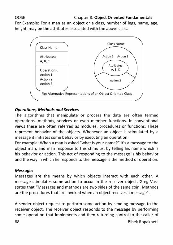
OOSE Chapter 8: Object Oriented Fundamentals
88 Bibek Ropakheti
For Example: For a man as an object or a class, number of legs, name, age, height, may be the attributes associated with the above class.
Operations, Methods and Services The algorithms that manipulate or process the data are often termed operations, methods, services or even member functions. In conventional views these are often referred as modules, procedures or functions. These represent behavior of the objects. Whenever an object is stimulated by a message it initiates some behavior by executing an operation. For example: When a man is asked “what is your name?” it’s a message to the object man, and man response to this stimulus, by telling his name which is his behavior or action. This act of responding to the message is his behavior and the way in which he responds to the message is the method or operation. Messages Messages are the means by which objects interact with each other. A message stimulates some action to occur in the receiver object. Greg Vass states that “Messages and methods are two sides of the same coin. Methods are the procedures that are invoked when an object receives a message”. A sender object request to perform some action by sending message to the receiver object. The receiver object responds to the message by performing some operation that implements and then returning control to the caller of
Class Name
Fig: Alternative Representations of an Object Oriented Class
Class Name Attributes: A, B, C Operations: Action 1 Action 2 Action 3
Action 1 Action 2
Action 3
Attributes A, B, C

OOSE Chapter 8: Object Oriented Fundamentals
89 Bibek Ropakheti
the message or message sending object. Message ties an object oriented system together. Messages provide insight into the behavior of individual objects and the object oriented system as a whole. Abstraction, Encapsulation, Inheritance, and Polymorphism Abstraction is a technique of problem solving in which details are grouped into a single common concept which can be viewed as a single entity and non essential information ignored. Abstraction enables the designer to focus on the essential details of a program component with little concern for lower level details. In object oriented approach class represents the data abstraction. Berard[BER95] defines encapsulation as the binding of collection of items together. For OO Systems, encapsulation encompasses the responsibilities of a class, including its attributes and operations, and the states of the class, as defined by specific attributes values. The major benefits of encapsulation are:
• Information Hiding • Information Security • Weak Coupling • High or Strong Cohesion
Inheritance is a mechanism that enables the responsibilities of one object to be propagated to other objects. Inheritance occurs throughout all the levels of a class hierarchy. Inheritance allows us to define a new class by extending
Message [Receiver, Method 1, Parameters]
Receiver Object
Message [Sender, Method A, Parameters] ] Sender Object
Fig: Object Oriented Concept
Method 1
Method 2
Attributes
Method A
Method B
Attributes

OOSE Chapter 8: Object Oriented Fundamentals
90 Bibek Ropakheti
or modifying an existing class. The original class is called the base class or super class and the new class obtained through inheritance is called derived class or subclass. Subclass is the specialization of its base class and the super class is the generalization of its derived class. Hence, this inheritance relationship is called generalization-specialization relationship. Polymorphism implies one interface multiple methods. Broadly, it is a feature that allows one interface to be used for a general class of actions. The specific action is determined by the exact nature of the situation. It helps reduction of complexity by allowing the same interface to be used to specify a general class of action. It is the compiler’s job to select the specific action as it applies to each situation. We do not need to select the method or specific action manually. We just need to remember and utilize the general interface. The basic elements of an object model are:
• Classes and Objects • Attributes • Operations • Messages
In order to develop object model the elements must be identified, specified and defined. The first step in identifying the OO concepts is identifying classes and objects. References:
1. R.S Pressman, Software Engineering: A Practitioner’s Approach, 5/e, Mc Graw Hill International Edition
2. R. Mall, Foundations of Software Engineering 3. G. Booch, Object Oriented Analysis and Design with Applications 2/e,
Pearson Education Asia 4. G. Booch, I. Jacobson, J. Rumbaugh, Object Oriented Software
Engineering 5. T. Budd, An Introduction to Object Oriented Programming, 2/e,
Addition-Wesley, Pearson Education Asia

OOSE Chapter 9: Unified Modeling Language
91 Bibek Ropakheti
Chapter 9 Unified Modeling Language Unified Modeling Language Fundamentals UML notations Structural Models:
(Concepts: class, object, relationship, interfaces, packages, instances) Class Diagram Object Diagram
Behavioral Models (Concepts: interactions, scenarios, use cases, event, signal, process) Use Case Diagram Interaction Diagram Collaboration Diagram State Transition Diagram Activity Diagram
Architectural Models (Concepts: components, deployment, collaboration, patterns, etc) Component Diagram Deployment Diagram
UML based any CASE tool and its use. All the definitions and the techniques of developing different models have already been provided as classroom note. For further details consult references. References:
1. R. Mall, Foundations of Software Engineering. 2. G. Booch, Object Oriented Analysis and Design with Applications 2/e
Pearson 3. G. Booch, I. Jacobson, J. Rumbaugh, Object Oriented Software
Engineering. 4. G. Booch, J.Rumbaugh, J. Jacobson, The Unified Modeling Language –
User Guide Addison – Wesley 5. C. Larman, Applying UML and patterns, Pearson
OOSE Chapter 10: Object Oriented Analysis
92 Bibek Ropakheti
Chapter 10 Object Oriented Analysis OO based Analysis Unified approach Domain and reuse analysis Identification of class and objects Identification of class and object semantics Use case and CRC modeling Structure and Hierarchy Subject and Subsystems Definition Identify Class and Object Relationship Object- Relationship Modeling Events and States Identification State representation Systems behavior representation Management of OO Software Projects In modern software projects, the management of such projects can be done by using the following activities:
• Establishing a common process framework for a project. • Using the framework and historical metrics to develop effort and time
estimated. • Establishing deliverables and milestones that will enable progress to
be measured. • Defining checkpoints for risk management, quality assurance and
control. • Managing the changes that invariably occur as the project progresses. • Tracking, monitoring and controlling progress.

OOSE Chapter 10: Object Oriented Analysis
93 Bibek Ropakheti
Planning Analysis Design Review and Refinement
Analysis Design
Early Analysis/ Design Iterations Analysis Design
Review and Refinement First Prototype
Planning Analysis Design Extract
Reusable Classes
Prototype Test
Review and Refinement Second Prototype
Planning Analysis Design Extract
Reusable Classes
Prototype Test
Review and Refinement Nth Iteration
Planning Analysis Design Extract
Reusable Classes
Prototype Test
Fig: Typical Process Sequence for OO Project
Object Oriented Analysis Modeling Object oriented analysis focus on the modeling the system using five basic principles:
• Modeling the Information Domain • Describing the Function • Representing the Behavior • Partitioning the System In terms of Data Model, Functional Model
and Behavioral Model in order to Expose Greater Details • Using Iterative Modeling Techniques Develop Better Models
Based on these principles, many different object oriented analysis techniques had been developed. The most popular have been Object Modeling Technique by Rumbaugh, Booch Method by Grady Booch, Object Oriented Software Engineering or Jacobson Method by Jacobson, Coad and Yourdon
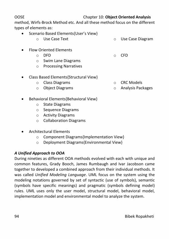
OOSE Chapter 10: Object Oriented Analysis
94 Bibek Ropakheti
method, Wirfs-Brock Method etc. And all these method focus on the different types of elements as:
• Scenario Based Elements{User’s View} o Use Case Text o Use Case Diagram
• Flow Oriented Elements
o DFD o CFD o Swim Lane Diagrams o Processing Narratives
• Class Based Elements{Structural View}
o Class Diagrams o Object Diagrams
o CRC Models o Analysis Packages
• Behavioral Elements{Behavioral View}
o State Diagrams o Sequence Diagrams o Activity Diagrams o Collaboration Diagrams
• Architectural Elements
o Component Diagrams{Implementation View} o Deployment Diagrams{Environmental View}
A Unified Approach to OOA During nineties as different OOA methods evolved with each with unique and common features, Grady Booch, James Rumbaugh and Ivar Jacobson came together to developed a combined approach from their individual methods. It was called Unified Modeling Language. UML focus on the system using the modeling notations governed by set of syntactic (use of symbols), semantic (symbols have specific meanings) and pragmatic (symbols defining model) rules. UML uses only the user model, structural model, behavioral model, implementation model and environmental model to analyze the system.
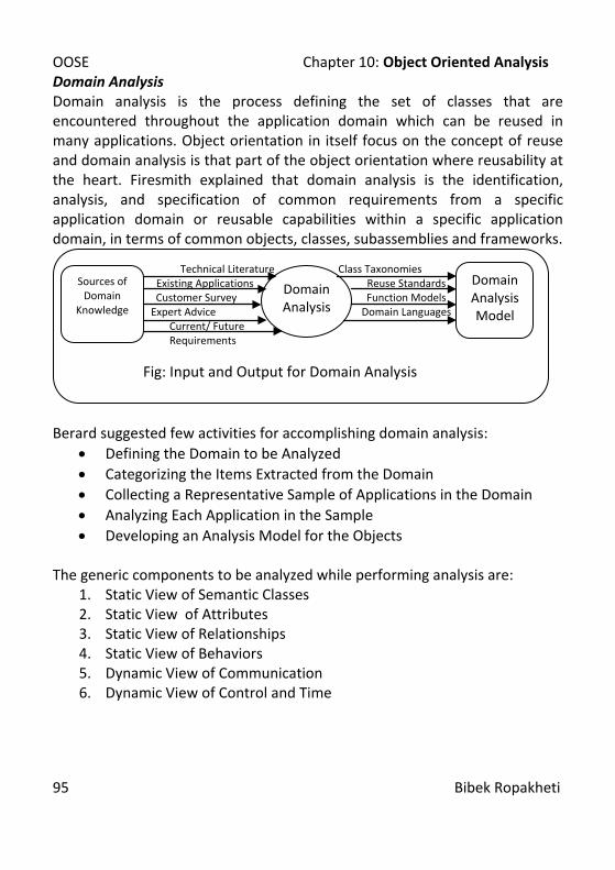
OOSE Chapter 10: Object Oriented Analysis
95 Bibek Ropakheti
Domain Analysis Domain analysis is the process defining the set of classes that are encountered throughout the application domain which can be reused in many applications. Object orientation in itself focus on the concept of reuse and domain analysis is that part of the object orientation where reusability at the heart. Firesmith explained that domain analysis is the identification, analysis, and specification of common requirements from a specific application domain or reusable capabilities within a specific application domain, in terms of common objects, classes, subassemblies and frameworks.
Berard suggested few activities for accomplishing domain analysis:
• Defining the Domain to be Analyzed • Categorizing the Items Extracted from the Domain • Collecting a Representative Sample of Applications in the Domain • Analyzing Each Application in the Sample • Developing an Analysis Model for the Objects
The generic components to be analyzed while performing analysis are:
1. Static View of Semantic Classes 2. Static View of Attributes 3. Static View of Relationships 4. Static View of Behaviors 5. Dynamic View of Communication 6. Dynamic View of Control and Time
Technical Literature Class Taxonomies Existing Applications Reuse Standards Customer Survey Function Models
Expert Advice Domain Languages Current/ Future Requirements
Fig: Input and Output for Domain Analysis
Sources of Domain
Knowledge
Domain Analysis Model
Domain Analysis
OOSE Chapter 10: Object Oriented Analysis
96 Bibek Ropakheti
The Object Oriented Analysis starts with the development of Use Cases. Once use cases are derived, conceptual models as a part of analysis model are derived. After conceptual modeling, behavioral modeling for analysis is done. Then we move forward to design phase. While developing conceptual models, first of all the concepts i.e. classes, objects, attributes, relationships, operations etc. are identified. One of the good ways of conceptual modeling is through CRC modeling. CRC modeling or classes, responsibilities collaborator modeling is the modeling technique where index cards are use to represent the classes and indicate their responsibilities and collaborator. Once concepts present in the system are recognized the most important part of analysis starts. It is the development of associations and relationships between the concepts. Identifying Classes and Objects The OO process must be started by identifying what are the objects and classes that are available in the problem domain. By examining problem statement or by performing a grammatical parse on the processing narrative for the system to be built, the objects are identified. In grammatical parse, nouns and noun phrases or noun clauses represents object. Generally, objects can be:
• External Entities: Produce or consume information to be used by the computer based system.
• Things: Part of the information domain for the problem. • Occurrences or Events: Occur within the context of system operation. • Roles: Played by people those interact with the system. • Organizational Units: Relevant to an application. • Places: Establish the context of the problem and the overall function
of the system. • Structures: Define a class of objects or in the extreme, related classes
and objects.

OOSE Chapter 10: Object Oriented Analysis
97 Bibek Ropakheti
And the characteristics of objects must be: • Retain Information • Needed Services • Multiple Attributes
• Common Attributes • Common Operations • Essential Requirements
Once the objects are identified they are generalized and the classes are identified. On identification of classes and objects the next step is specifying attributes. Specifying Attributes Attributes describe an object that has been selected for the inclusion in the analysis model. In essence, it is the attribute that define the object. Attributes belong to any object. To develop meaningful set of attributes, the analyst studies the processing narratives again and identifies the attributes belonging to the object. Those identified attributes are now listed down. Defining Operations After the attributes are listed, the operations on the attributes are to be defined. Operations define the behavior of an object and change the object’s attributes in some way. More specifically, an operation changes one or more attribute values that are contained within the object. So, we can describe that an operation must have ken of the nature of the object’s attributes and must be implemented in a manner that enables it to manipulate the data structures that have been derived from the attributes. Operations either manipulate data, computes or monitor an object for the occurrence of a controlling event. In grammatical parse, verbs represent operations. Inter Object Communication After the identification of objects, and their attributes and operations, the processes of identification of the associations between the objects are to be analyzed. The objects interact with each other through message. So, how a method of a class passes the message to another is to be concretely observed. Its inter object communication.
OOSE Chapter 10: Object Oriented Analysis
98 Bibek Ropakheti
Finalizing the Object Definition Finally iterations and refinements are to be done in order to properly identify and finalize the elements of object oriented modeling. The object definition as a whole consist of concept of object, attributes associated with it, the operations to fulfill the responsibilities of the object, the associations of an object with other objects which is achieved through message passing formalism. Once we have analyzed the basic concepts of object orientation, now let us examine the basic guidelines to manage the OO software projects. For Use Case and CRC Modeling, Consult Software Engineering: A Practitioner’s Approach, Fifth Edition , by Roger S. Presssman. Classification and Assembly Structures {Defining Structures and Hierarchies} The next process analyst has to do is to classify the identified classes into structures and the resultant will be a hierarchy of classes and sub classes. The classes are categorized into a structure of generalization/specialization classes. It is implemented as inheritance structure. Another way to define the assembly structure of the classes is done through the composition mechanism. An object may be represented using different other objects and it is called composition of an object using others. Defining Subjects and Subsystems The analysis of a complex system may results in the identification of hundreds of classes and tens of structures. Now using the bottom up approach, the group of associated structures and classes within the structure are classified under a common subject to develop the subsystem. These common groups of classes or subsystems are each bounded by a common responsibility to be fulfilled by the subsystem. Instance Connections and Message Paths While associating the classes, we need to confirm the associations and relationships between them. The communication mechanism between the classes is what binds a system or a subsystem together. How class

OOSE Chapter 10: Object Oriented Analysis
99 Bibek Ropakheti
collaborates or interacts with the classes is answered through how they pass messages within the subsystem. Using behavioral views the message paths and the collaboration between the subsystem components are defined. Modeling tools like state chart diagrams, activity diagrams, sequence diagrams, contracts, collaboration diagrams, etc. are used to represent the behavioral view. For O-R Modeling, Events and States Identification, State Representation and Systems Behavior Representation, Consult Software Engineering: A Practitioner’s Approach, Fifth Edition, by Roger S. Presssman OOA and Prototyping As OOA focus on iterative development of the software and the prototyping model as well focus on rapid development of software using iterative approach, both of them complement each other. OOA also helps in development of the system with the development of the prototypes rather than complete software within a cycle. References:
1. R. S. Pressman, Software Engineering: A Practitioner’s Approach, 5/e, Mc Graw Hill International Edition
2. R. Mall, Foundations of Software Engineering. 3. G. Booch, Object Oriented Analysis and Design with Applications 2/e
Pearson 4. G. Booch, I. Jacobson, J. Rumbaugh, Object Oriented Software
Engineering. 5. G. Booch, J.Rumbaugh, J. Jacobson, The Unified Modeling Language –
User Guide Addison – Wesley 6. C. Larman, Applying UML and patterns, Pearson

OOSE Chapter 11: Object Oriented Design
100 Bibek Ropakheti
Chapter 11 Object Oriented Design OOD Concepts Design Issues Unified Approach to design Partitioning of analysis model Concurrency and subsystem allocation Task management component User interface component Data management component Resource management component Inter-subsystem Communication Object description Data structure Component and interfaces Design Patterns and reuse Elaboration and implementation of Use cases Class Object collaboration, Interaction, STD diagram etc. Origins of Object Oriented Design The design of object oriented software requires the definition of a multilayered software architecture, the specification of subsystems that perform required functions and provide infrastructure support, a description of objects and classes that form the building blocks or the architecture of the system and a description of the communication mechanisms that allow data to flow between layers, subsystems and objects. An object oriented system draws upon class definitions that are derived from the analysis model. Some of these definitions will have to be built from scratch, but many other may be reused if appropriate design patterns are recognized. OOD establishes a design blueprint that enables a software engineer to define the OO architecture in a manner that maximizes reuse, thereby improving development speed and end product quality.
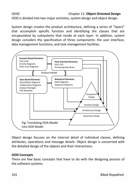
OOSE Chapter 11: Object Oriented Design
101 Bibek Ropakheti
OOD is divided into two major activities, system design and object design. System design creates the product architecture, defining a series of “layers” that accomplish specific function and identifying the classes that are encapsulated by subsystems that reside at each layer. In addition, system design considers the specification of three components: the user interface, data management functions, and task management facilities.
Object design focuses on the internal detail of individual classes, defining attributes, operations and message details. Object design is concerned with the detailed design of the objects and their interactions. OOD Concepts There are few basic concepts that have to do with the designing process of the software systems.
Analysis Model
Scenario Based Elements: Use Cases Activity Diagrams Swim Lane Diagrams
Flow Oriented Elements: DFD, CFD Processing Narratives
Behavioral Elements: State Diagrams Sequence Diagrams
Class Based Elements: Class/Object Diagrams Collaboration Diagrams Analysis Packages CRC Modeling
Interface Design
Architectural Design
Data/Class Design
Component Design
Fig: Translating OOA Model into OOD Model
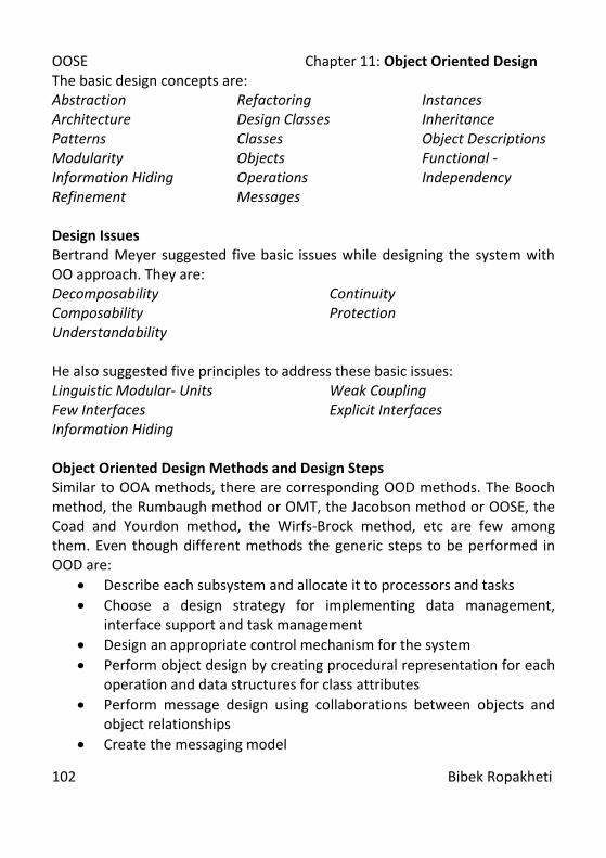
OOSE Chapter 11: Object Oriented Design
102 Bibek Ropakheti
The basic design concepts are: Abstraction Architecture Patterns Modularity Information Hiding Refinement
Refactoring Design Classes Classes Objects Operations Messages
Instances Inheritance Object Descriptions Functional -Independency
Design Issues Bertrand Meyer suggested five basic issues while designing the system with OO approach. They are: Decomposability Composability Understandability
Continuity Protection
He also suggested five principles to address these basic issues: Linguistic Modular- Units Few Interfaces
Weak Coupling Explicit Interfaces
Information Hiding Object Oriented Design Methods and Design Steps Similar to OOA methods, there are corresponding OOD methods. The Booch method, the Rumbaugh method or OMT, the Jacobson method or OOSE, the Coad and Yourdon method, the Wirfs-Brock method, etc are few among them. Even though different methods the generic steps to be performed in OOD are:
• Describe each subsystem and allocate it to processors and tasks • Choose a design strategy for implementing data management,
interface support and task management • Design an appropriate control mechanism for the system • Perform object design by creating procedural representation for each
operation and data structures for class attributes • Perform message design using collaborations between objects and
object relationships • Create the messaging model

OOSE Chapter 11: Object Oriented Design
103 Bibek Ropakheti
• Review the design model and iterate as required Unified Approach And the best approach derived from the above methods is unified approach to object oriented design. OOD using UML focuses on two level of design approach. They are system design and object design.
For Partitioning of analysis model, Concurrency and subsystem allocation, Task management component, User interface component, Data management component, Resource management component, Inter-subsystem Communication, Consult Software Engineering: A Practitioner’s Approach, Fifth Edition, by Roger S. Presssman Object Descriptions A design description of an object which is an instance of a class or subclass can take one of two forms:
Fig: Process Flow for Object Oriented Design
System Design
Object Design
User Interface Design
Object Oriented Analysis
Task Management Design
Data Management Design

OOSE Chapter 11: Object Oriented Design
104 Bibek Ropakheti
Protocol Description: It establishes the interface of an object by defining each message that the object can receive and the related operation that the object performs when it receives the message. Implementation Description: It shows implementation details for each operation implied by a message that is passed to an object. Class and Object Definition The first step in the object oriented design is the determination of the definition of the class or object definition. The class and objects identified during the analysis phase are precisely re evaluated and the definition of the class or the object is derived. Refining Operations Once the methods to be developed from the analysis model are assigned the responsibilities then the design of these methods are to be developed. Operations or methods are the inseparable components of any class or object. The responsibility assignment can be done using patterns like GRASP. GRASP stands for General Responsibility Assignment Software Patterns. Program Components and Interfaces The design of the interface within the system is the next design process to be accomplished. The architectural design to accomplish the subsystem analysis is transformed into design, next. Representing Class and Object Relationships The object relationship modeling is the next process of designing. The inter class and inter object relationship is modeled during this design phase. Modularizing the Design The designing is the way of problem solving so that the complex problem is decomposed and it became easier to develop the system. Modularity is one of the most important features of software designing. The design should not be done as a whole rather it should be done in a way that the problem as well as the process of solving it should be done in parts. The module we consider during the OOD is actually class and object.
OOSE Chapter 11: Object Oriented Design
105 Bibek Ropakheti
Implementation Detail Design The design thus achieved is transformed into the programs. It is the implementation of the detailed design. Design Patterns and Reuse An object oriented system draws upon class definitions that are derived from the analysis model. Some of these definitions will have to be built from scratch, but many other may be reused if appropriate design patterns are recognized. OOD establishes a design blueprint that enables a software engineer to define the OO architecture in a manner that maximizes reuse, thereby improving development speed and end product quality. Design Patterns characterize a problem and corresponding patterns that can be combined to create a solution for the problem. These patterns of reoccurring patterns of classes and communicating objects are common in OO Systems and these patterns solve specific design problems and make OOD more flexible, elegant and reusable. They help engineers reuse successful designs by designing newer subsystems on the foundations of prior experience. We should always look forward for such design patterns where reusability is possible. All design patterns can be described by specifying the following information:
• Name • Intent • “Design forces” that motivates pattern • The solution that mitigates these forces • The classes required to implement the solution • The responsibilities and collaborations among solution classes • Guidance that leads to effective implementation • Example are source code or source code templates • Cross references related to design patterns
Generally, design patterns in codes and designs are implemented using two mechanisms:
OOSE Chapter 11: Object Oriented Design
106 Bibek Ropakheti
• Inheritance: The use of existing design patterns as templates for subclass, that use attributes and operations from the existing patterns.
• Composition: It leads to aggregate objects. The formation of complex objects is done by assembling sets of design patterns.
For Elaboration and implementation of Use cases Class, Object collaboration, Interaction, STD diagram etc., Consult Software Engineering: A Practitioner’s Approach, Fifth Edition, by Roger S. Presssman References:
1. R. S. Pressman, Software Engineering: A Practitioner’s Approach, 5/e, Mc Graw Hill International Edition
2. R. Mall, Foundations of Software Engineering. 3. G. Booch, Object Oriented Analysis and Design with Applications 2/e
Pearson 4. G. Booch, I. Jacobson, J. Rumbaugh, Object Oriented Software
Engineering. 5. G. Booch, J.Rumbaugh, J. Jacobson, The Unified Modeling Language –
User Guide Addison – Wesley 6. C. Larman, Applying UML and patterns, Pearson