CMM-GD&T MEASUREMENT PLANNING - … to CMM-GD&T Measurement Planning Learning Objectives of this...
16
CMM-GD&T MEASUREMENT PLANNING EDUCATION AN EDUCATIONAL PRESENTATION FROM THE LEADING MANUFACTURER OF METROLOGY INSTRUMENTS ASME Y14.5 ISO 1101 EDU-14001A-H
Transcript of CMM-GD&T MEASUREMENT PLANNING - … to CMM-GD&T Measurement Planning Learning Objectives of this...
Bulletin No. 2183
CMM-GD&T MEASUREMENT PLANNING
EDUC
ATIO
NAN EDUCATIONAL PRESENTATION FROM THE LEADING MANUFACTURER OF METROLOGY INSTRUMENTS
ASME Y14.5
ISO 1101
EDU-14001A-H
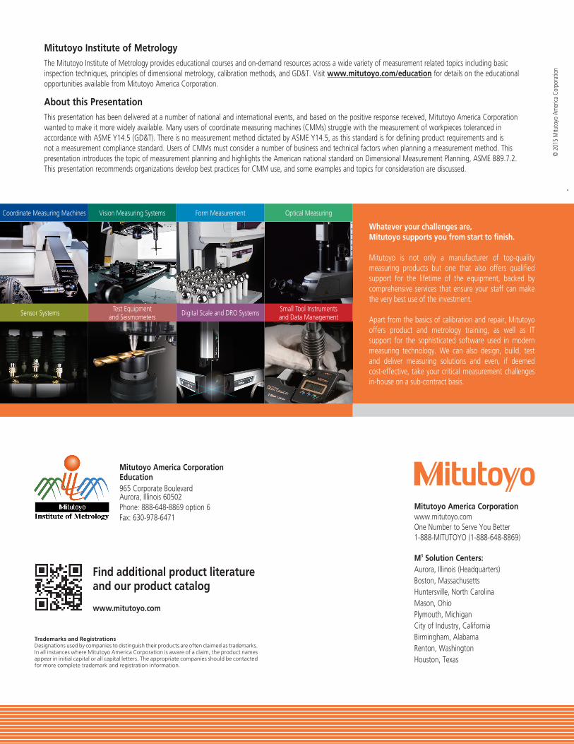
Whatever your challenges are, Mitutoyo supports you from start to finish.
Mitutoyo is not only a manufacturer of top-quality measuring products but one that also offers qualified support for the lifetime of the equipment, backed by comprehensive services that ensure your staff can make the very best use of the investment.
Apart from the basics of calibration and repair, Mitutoyo offers product and metrology training, as well as IT support for the sophisticated software used in modern measuring technology. We can also design, build, test and deliver measuring solutions and even, if deemed cost-effective, take your critical measurement challenges in-house on a sub-contract basis.
Coordinate Measuring Machines
Sensor Systems
Vision Measuring Systems
Test Equipment and Seismometers
Form Measurement
Digital Scale and DRO Systems
Optical Measuring
Small Tool Instruments and Data Management
Mitutoyo America Corporationwww.mitutoyo.comOne Number to Serve You Better1-888-MITUTOYO (1-888-648-8869)
M3 Solution Centers:Aurora, Illinois (Headquarters)Boston, MassachusettsHuntersville, North CarolinaMason, OhioPlymouth, MichiganCity of Industry, CaliforniaBirmingham, AlabamaRenton, WashingtonHouston, Texas
Mitutoyo Institute of MetrologyThe Mitutoyo Institute of Metrology provides educational courses and on-demand resources across a wide variety of measurement related topics including basic inspection techniques, principles of dimensional metrology, calibration methods, and GD&T. Visit www.mitutoyo.com/education for details on the educational opportunities available from Mitutoyo America Corporation.
About this PresentationThis presentation has been delivered at a number of national and international events, and based on the positive response received, Mitutoyo America Corporation wanted to make it more widely available. Many users of coordinate measuring machines (CMMs) struggle with the measurement of workpieces toleranced in accordance with ASME Y14.5 (GD&T). There is no measurement method dictated by ASME Y14.5, as this standard is for defining product requirements and is not a measurement compliance standard. Users of CMMs must consider a number of business and technical factors when planning a measurement method. This presentation introduces the topic of measurement planning and highlights the American national standard on Dimensional Measurement Planning, ASME B89.7.2. This presentation recommends organizations develop best practices for CMM use, and some examples and topics for consideration are discussed.
© 2
015
Mitu
toyo
Am
erica
Cor
pora
tion
Mitutoyo America Corporation Education965 Corporate BoulevardAurora, Illinois 60502Phone: 888-648-8869 option 6Fax: 630-978-6471
Find additional product literature and our product catalog
www.mitutoyo.com
Trademarks and RegistrationsDesignations used by companies to distinguish their products are often claimed as trademarks. In all instances where Mitutoyo America Corporation is aware of a claim, the product names appear in initial capital or all capital letters. The appropriate companies should be contacted for more complete trademark and registration information.
Introduction to CMM-GD&T
Measurement Planning
Learning Objectives of this Presentation
• Identify roadblocks to success in the implementation of modern measuring equipment for the measurement of geometrical tolerances (GD&T).
• Apply techniques for the development of optimal measurement plans and their deployment across an organization.
• Identify differences between US and international tolerancing standards and analyze the impact.
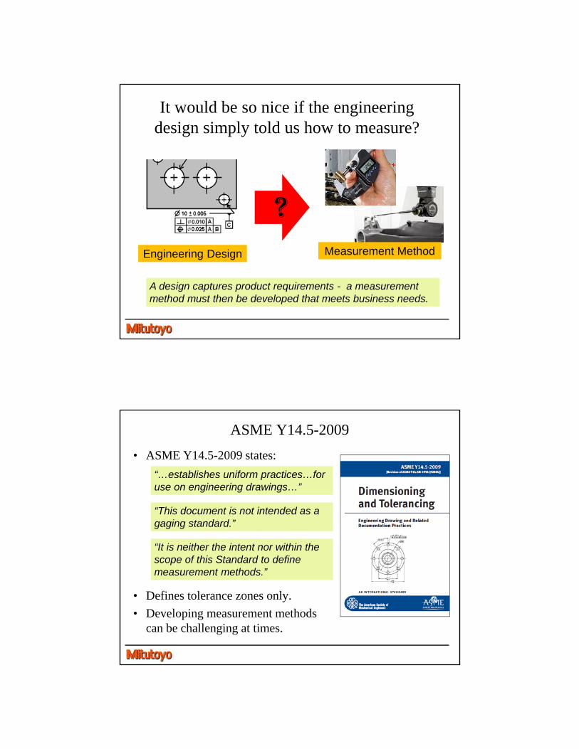
It would be so nice if the engineering design simply told us how to measure?
A design captures product requirements - a measurement method must then be developed that meets business needs.
Engineering Design Measurement Method
?
ASME Y14.5-2009
• ASME Y14.5-2009 states:
• Defines tolerance zones only.
• Developing measurement methods can be challenging at times.
“This document is not intended as a gaging standard.”
“…establishes uniform practices…for use on engineering drawings…”
“It is neither the intent nor within thescope of this Standard to define measurement methods.”
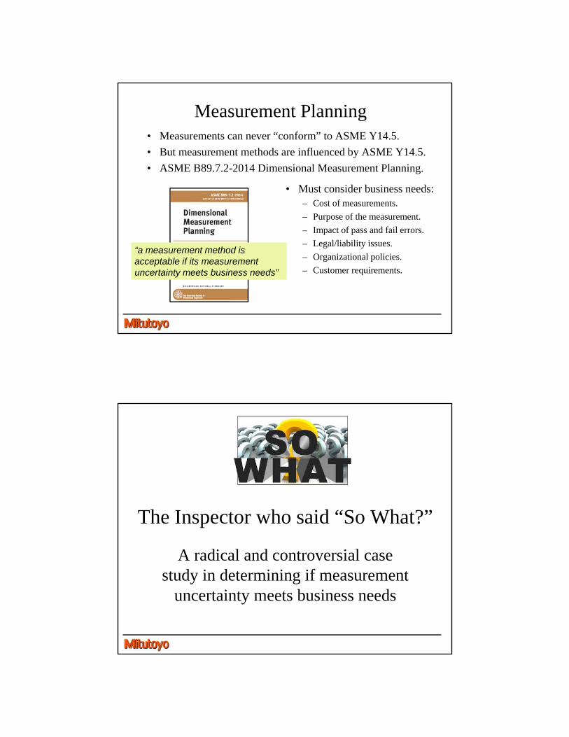
Measurement Planning• Measurements can never “conform” to ASME Y14.5.
• But measurement methods are influenced by ASME Y14.5.
• ASME B89.7.2-2014 Dimensional Measurement Planning.
• Must consider business needs:– Cost of measurements.
– Purpose of the measurement.
– Impact of pass and fail errors.
– Legal/liability issues.
– Organizational policies.
– Customer requirements.
“a measurement method is acceptable if its measurement uncertainty meets business needs”
The Inspector who said “So What?”
A radical and controversial case study in determining if measurement
uncertainty meets business needs
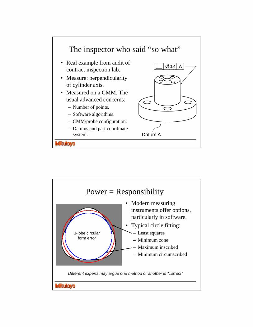
The inspector who said “so what”
• Real example from audit of contract inspection lab.
• Measure: perpendicularity of cylinder axis.
• Measured on a CMM. The usual advanced concerns:– Number of points.
– Software algorithms.
– CMM/probe configuration.
– Datums and part coordinate system.
[à|?).$|A]
Datum A
Power = Responsibility• Modern measuring
instruments offer options, particularly in software.
• Typical circle fitting:– Least squares
– Minimum zone
– Maximum inscribed
– Minimum circumscribed
Different experts may argue one method or another is “correct”.
3-lobe circular form error
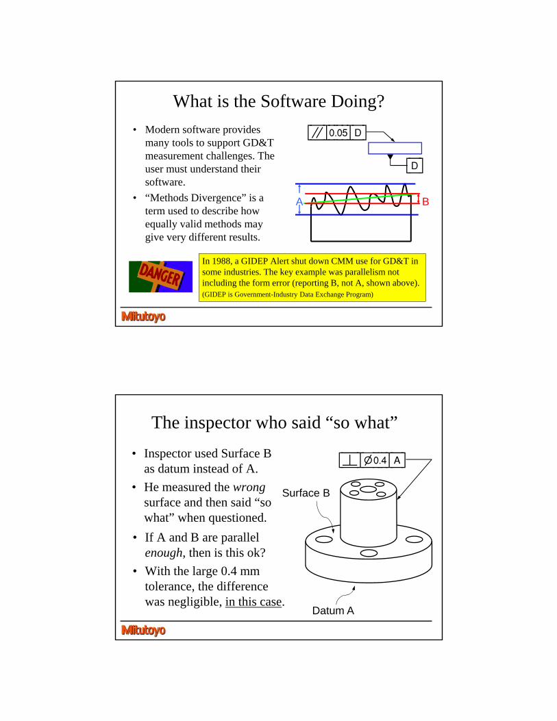
What is the Software Doing?
• Modern software provides many tools to support GD&T measurement challenges. The user must understand their software.
• “Methods Divergence” is a term used to describe how equally valid methods may give very different results.
In 1988, a GIDEP Alert shut down CMM use for GD&T in some industries. The key example was parallelism not including the form error (reporting B, not A, shown above).(GIDEP is Government-Industry Data Exchange Program)
BA
¯
[â|).)%|D]
[D]
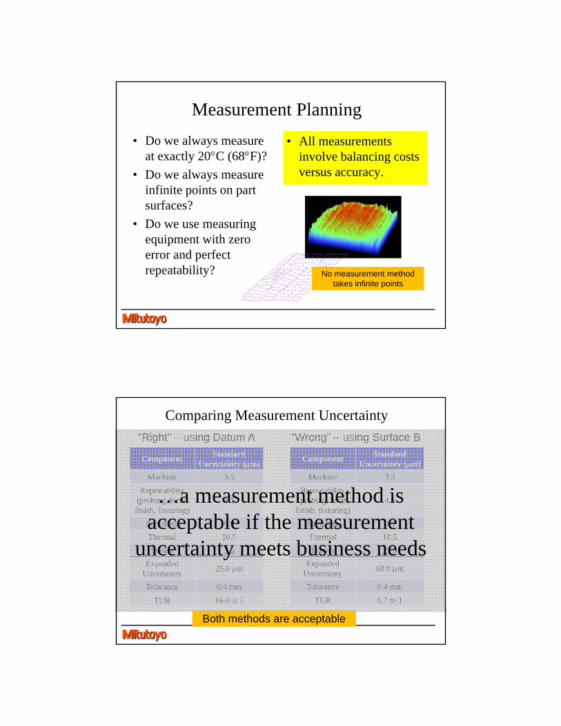
The inspector who said “so what”
• Inspector used Surface B as datum instead of A.
• He measured the wrongsurface and then said “so what” when questioned.
• If A and B are parallel enough, then is this ok?
• With the large 0.4 mm tolerance, the difference was negligible, in this case.
[à|?).$|A]
Datum A
Surface B
Measurement Planning
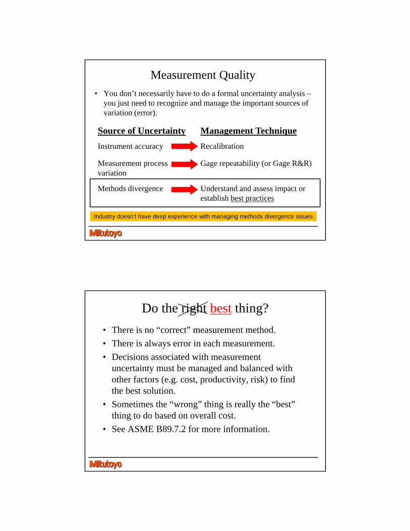
• Do we always measure at exactly 20C (68F)?
• Do we always measure infinite points on part surfaces?
• Do we use measuring equipment with zero error and perfect repeatability?
• All measurements involve balancing costs versus accuracy.
No measurement method takes infinite points
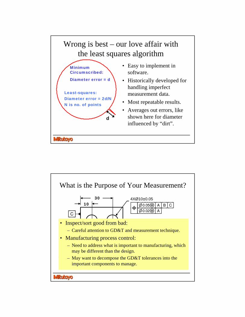
Comparing Measurement Uncertainty
ComponentStandard
Uncertainty (m)
Machine 3.5
Repeatability(probing, form, finish, fixturing)
4.5
Sampling 0.9
Thermal 10.5
Datum 3.5
Expanded Uncertainty
25.0 m
Tolerance 0.4 mm
TUR 16.0 to 1
ComponentStandard
Uncertainty (m)
Machine 3.5
Repeatability(probing, form, finish, fixturing)
4.5
Sampling 0.9
Thermal 10.5
Datum 27.5
Expanded Uncertainty
60.0 m
Tolerance 0.4 mm
TUR 6.7 to 1
“Wrong” – using Surface B“Right” – using Datum A
Both methods are acceptable
…a measurement method is acceptable if the measurement
uncertainty meets business needs
Measurement Quality
• You don’t necessarily have to do a formal uncertainty analysis –you just need to recognize and manage the important sources of variation (error).
Source of Uncertainty Management Technique
Instrument accuracy Recalibration
Measurement process variation
Gage repeatability (or Gage R&R)
Methods divergence Understand and assess impact or establish best practices
Industry doesn’t have deep experience with managing methods divergence issues
Do the right best thing?
• There is no “correct” measurement method.
• There is always error in each measurement.
• Decisions associated with measurement uncertainty must be managed and balanced with other factors (e.g. cost, productivity, risk) to find the best solution.
• Sometimes the “wrong” thing is really the “best” thing to do based on overall cost.
• See ASME B89.7.2 for more information.
Wrong is best – our love affair with the least squares algorithm
• Easy to implement in software.
• Historically developed for handling imperfect measurement data.
• Most repeatable results.
• Averages out errors, like shown here for diameter influenced by “dirt”.
d
Least-squares: Diameter error = 2d/NN is no. of points
Minimum Circumscribed:
Diameter error = d
What is the Purpose of Your Measurement?
1030
4525
¯[B]
[C]
4XØ10±0.05
«[?).)%é|A|B|C]
¯ »[?).)@é|A]
• Inspect/sort good from bad:– Careful attention to GD&T and measurement technique.
• Manufacturing process control:– Need to address what is important to manufacturing, which
may be different than the design.
– May want to decompose the GD&T tolerances into the important components to manage.
Is the Drawing even “Correct”?• In theory, tolerances are supposed to be
independent of measurement methods.
• But many drawing tolerances were developed based on data from measurements.
• In some cases, the drawing simply attempts to capture the functional manufacturing and measurement process.
Which came first –a functional part or the drawing?
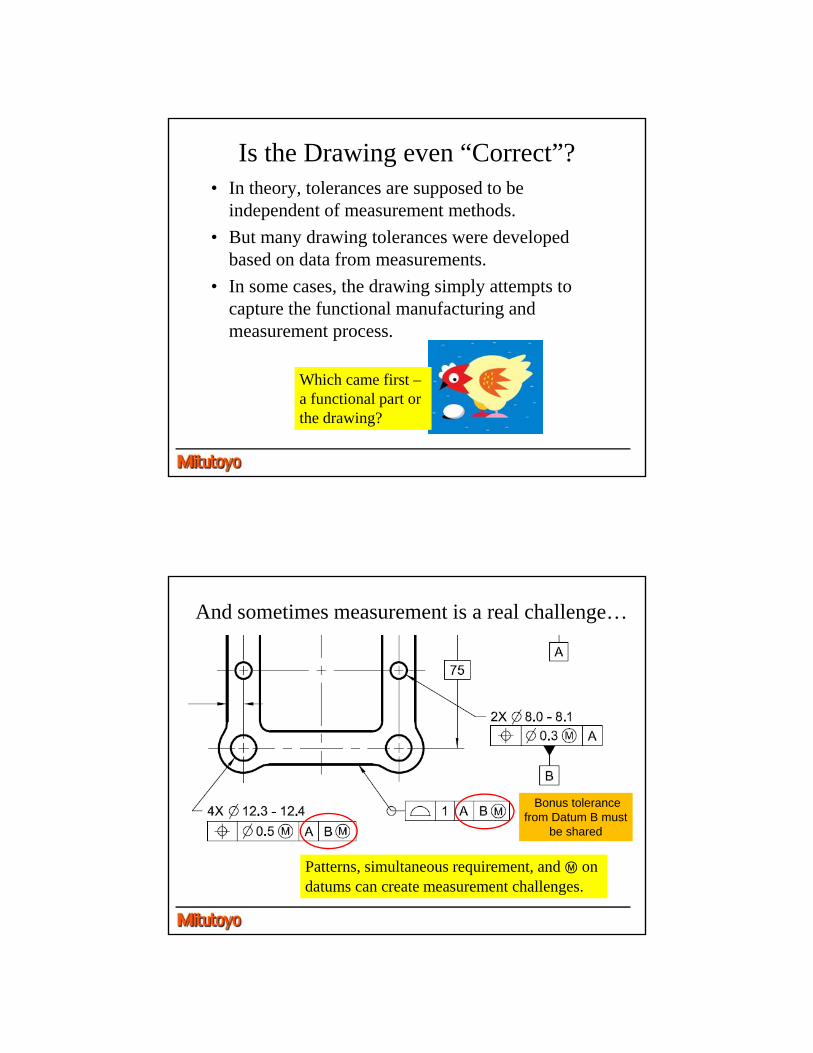
And sometimes measurement is a real challenge…
Patterns, simultaneous requirement, and Ô on datums can create measurement challenges.
Bonus tolerance from Datum B must
be shared
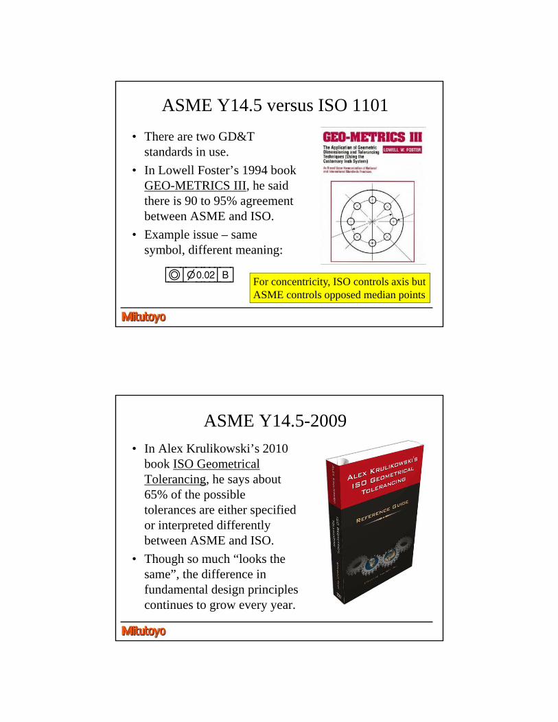
ASME Y14.5 versus ISO 1101
• There are two GD&T standards in use.
• In Lowell Foster’s 1994 book GEO-METRICS III, he said there is 90 to 95% agreement between ASME and ISO.
• Example issue – same symbol, different meaning:
[ã|?).)@|B]For concentricity, ISO controls axis butASME controls opposed median points
ASME Y14.5-2009
• In Alex Krulikowski’s 2010 book ISO Geometrical Tolerancing, he says about 65% of the possible tolerances are either specified or interpreted differently between ASME and ISO.
• Though so much “looks the same”, the difference in fundamental design principles continues to grow every year.
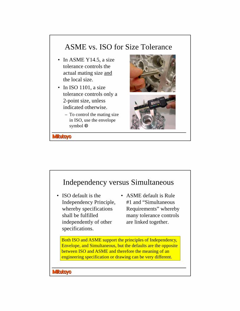
ASME vs. ISO for Size Tolerance
• In ASME Y14.5, a size tolerance controls the actual mating size andthe local size.
• In ISO 1101, a size tolerance controls only a 2-point size, unless indicated otherwise.– To control the mating size
in ISO, use the envelope symbol OE
Independency versus Simultaneous
• ISO default is the Independency Principle, whereby specifications shall be fulfilled independently of other specifications.
• ASME default is Rule #1 and “Simultaneous Requirements” whereby many tolerance controls are linked together.
Both ISO and ASME support the principles of Independency, Envelope, and Simultaneous, but the defaults are the opposite between ISO and ASME and therefore the meaning of an engineering specification or drawing can be very different.
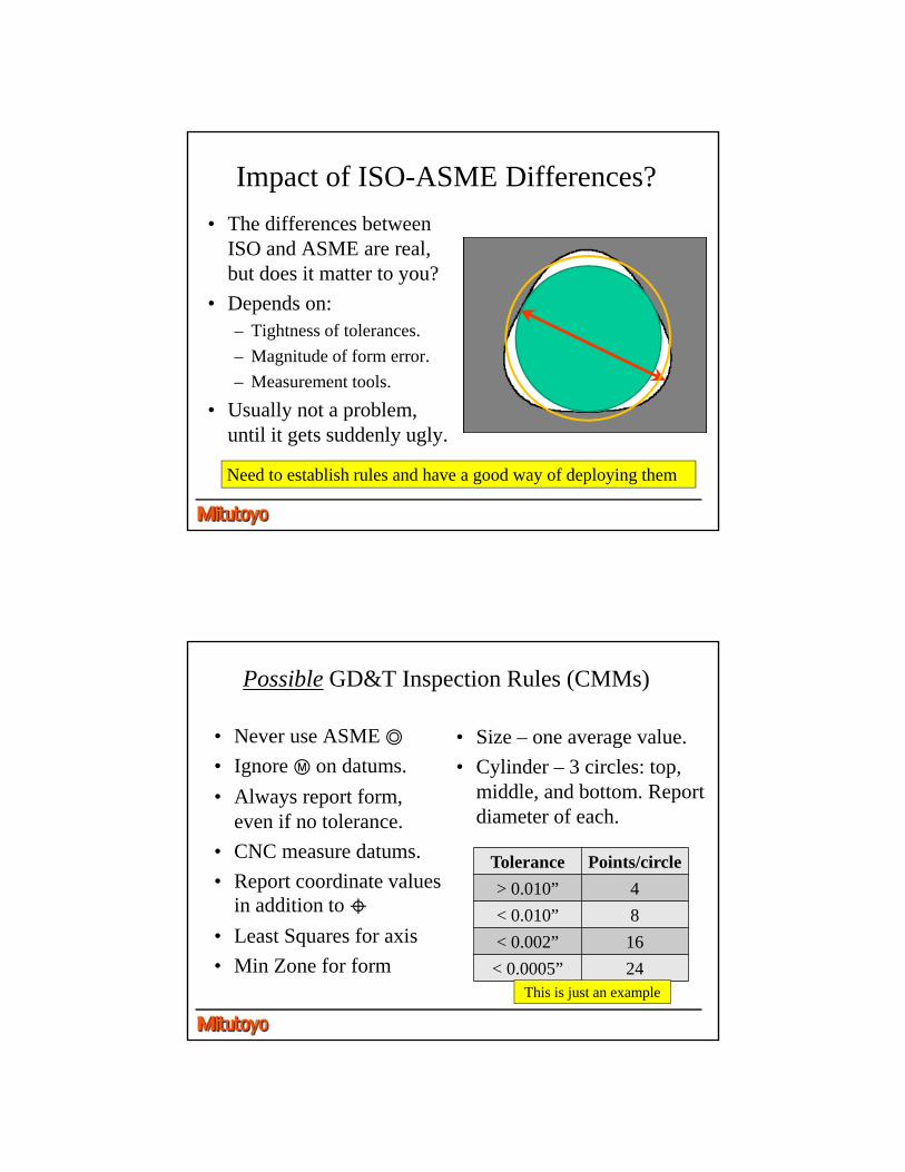
Impact of ISO-ASME Differences?
• The differences between ISO and ASME are real, but does it matter to you?
• Depends on:– Tightness of tolerances.
– Magnitude of form error.
– Measurement tools.
• Usually not a problem, until it gets suddenly ugly.
Need to establish rules and have a good way of deploying them
Possible GD&T Inspection Rules (CMMs)
• Never use ASME Î
• Ignore Ô on datums.
• Always report form, even if no tolerance.
• CNC measure datums.
• Report coordinate values in addition to Í
• Least Squares for axis
• Min Zone for form
• Size – one average value.
• Cylinder – 3 circles: top, middle, and bottom. Report diameter of each.
Tolerance Points/circle
> 0.010” 4
< 0.010” 8
< 0.002” 16
< 0.0005” 24This is just an example
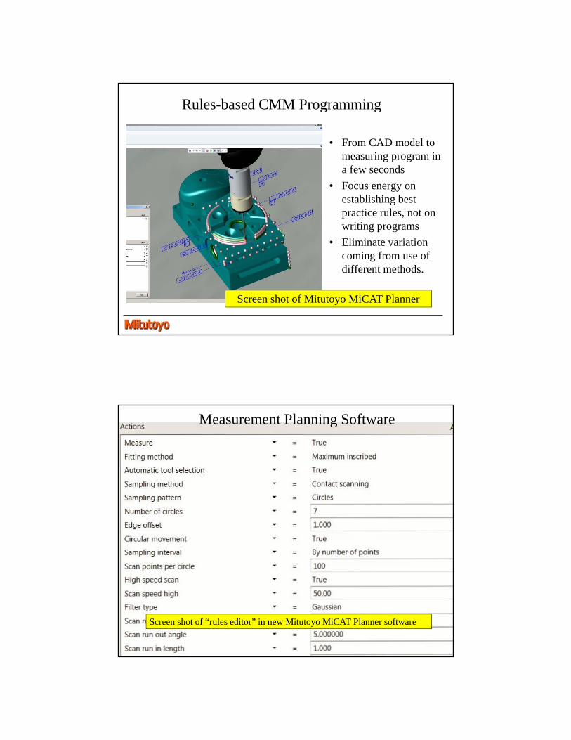
Rules-based CMM Programming
• From CAD model to measuring program in a few seconds
• Focus energy on establishing best practice rules, not on writing programs
• Eliminate variation coming from use of different methods.
Screen shot of Mitutoyo MiCAT Planner
Screen shot of “rules editor” in new Mitutoyo MiCAT Planner software
Measurement Planning Software
Summary
• Be aware of GD&T meaning, standards, and your measuring software tools.
• Define best practice rules for your organization.
• Don’t fall for the “right” trap. The “wrong” method might save your organization a lot of money.
• If form error is small, then less problems.
• If tolerances are tight, then be careful.
• New software tools make deploying best practices across organizations much easier.
Thank You
Visit our On-Demand Educational resources at:
www.mitutoyo.com/education