Clutch Installation and Maintenance 15.5 Easy Pedal and Heavy Duty Solo.
38
-
Upload
madeline-rasberry -
Category
Documents
-
view
229 -
download
5
Transcript of Clutch Installation and Maintenance 15.5 Easy Pedal and Heavy Duty Solo.


Clutch Installation and Clutch Installation and MaintenanceMaintenance
15.5 Easy Pedal and Heavy Duty Solo

Clutch BasicsClutch Basics
Provide means to disengage engine Provide means to disengage engine
Provide torsional vibration protectionProvide torsional vibration protection
Three factors that determine Clutch Three factors that determine Clutch capacitycapacity
1) Friction material1) Friction material
2) Surface area2) Surface area
3) Clamp load3) Clamp load
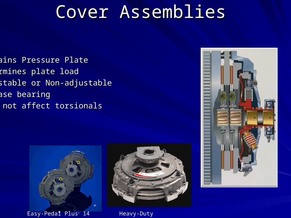
Cover AssembliesCover Assemblies
Contains Pressure PlateContains Pressure Plate
Determines plate loadDetermines plate load
Adjustable or Non-adjustableAdjustable or Non-adjustable
Release bearingRelease bearing
Does not affect torsionalsDoes not affect torsionals
Easy-Pedal Plus® 14” and 15.5” Heavy-Duty Solo™

Driven Discs “Dampers”Driven Discs “Dampers”
Torsional damper “Soft Rate”Torsional damper “Soft Rate”
Number of springsNumber of springs
Number of facingsNumber of facings
V.C.T. ™
7-Spring

Clutch BrakesClutch Brakes1-3/4 and 2.00”1-3/4 and 2.00”
Single piece “Torque Limiting”Single piece “Torque Limiting”
Two piece - non torque limitingTwo piece - non torque limiting

How They Work TogetherHow They Work Together
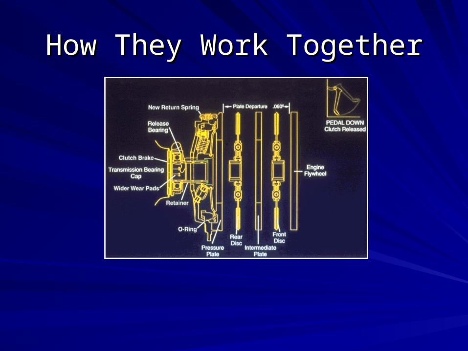
How They Work TogetherHow They Work Together
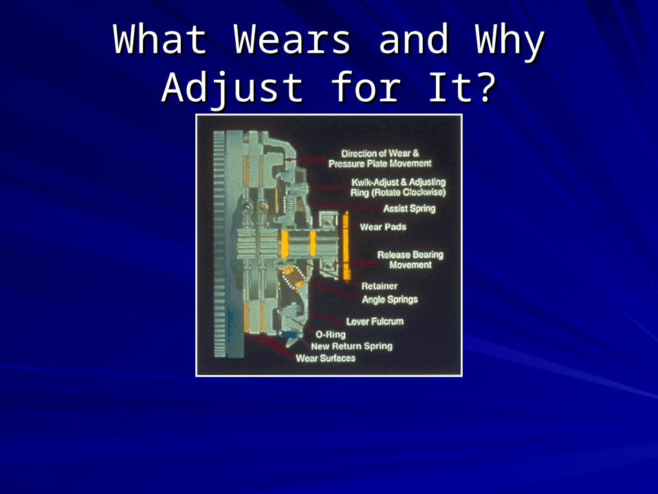
What Wears and Why Adjust for What Wears and Why Adjust for It?It?

When to Replace the ClutchWhen to Replace the Clutch
Eaton clutches should be replaced when internal Eaton clutches should be replaced when internal adjustment can not correct for a loss of free-pedal or can adjustment can not correct for a loss of free-pedal or can not compensate for a slipping clutchnot compensate for a slipping clutch
NOT: When you think it may slip soonNOT: When you think it may slip soon
When you think you have adjusted it too muchWhen you think you have adjusted it too much
When you think the lock strap wont hold the ringWhen you think the lock strap wont hold the ring

Easy-Pedal PlusEasy-Pedal Plus®® - 15.5” - 15.5”
Industry standard clutchIndustry standard clutch
Large application rangeLarge application range1050 to 2050 Lb-Ft1050 to 2050 Lb-Ft– 8-Spring8-Spring– 7-Spring7-Spring– 9-Spring9-Spring– 10-Spring10-Spring– V.C.T.™V.C.T.™
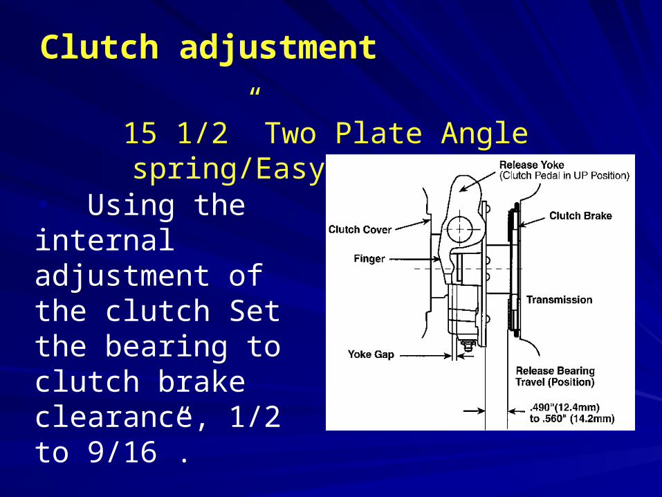
Clutch adjustment
15 1/2” Two Plate Angle spring/Easy Pedal Plus
• Using the internal adjustment of the clutch Set the bearing to clutch brake clearance, 1/2 to 9/16”.
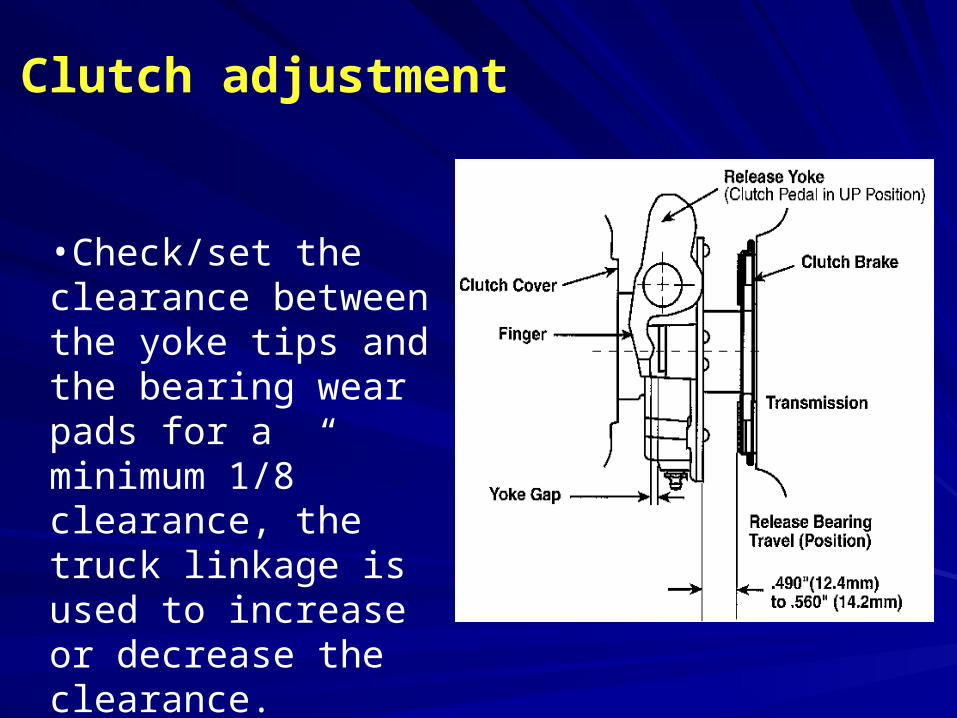
Clutch adjustment
•Check/set the clearance between the yoke tips and the bearing wear pads for a minimum 1/8” clearance, the truck linkage is used to increase or decrease the clearance.
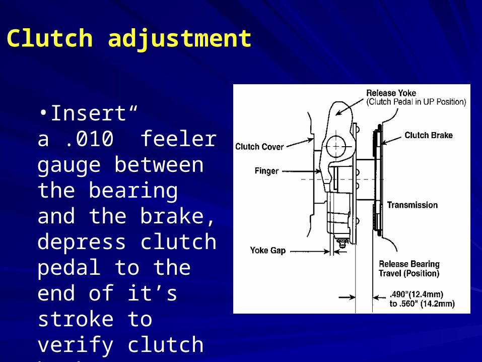
Clutch adjustment
•Insert a .010” feeler gauge between the bearing and the brake, depress clutch pedal to the end of it’s stroke to verify clutch brake squeeze.
Clutch adjustment
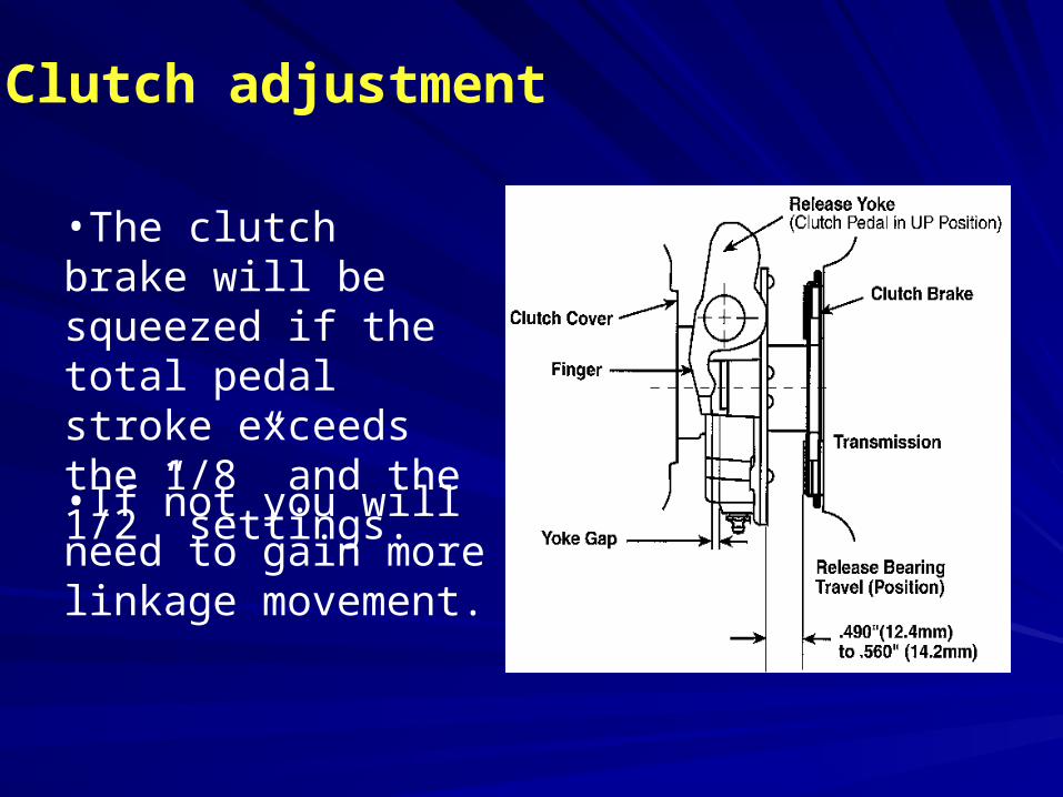
•The clutch brake will be squeezed if the total pedal stroke exceeds the 1/8” and the 1/2” settings.
•If not you will need to gain more linkage movement.
Clutch adjustment
If the brake is not being squeezed, do not change the 1/2” and 1/8” settings.
•Check linkage for worn components.
•Verify linkage is reassembled in correct hole locations.
•Increase pedal stroke (raising upper and lowering lower pedal stops).

Clutch adjustment
•Measure and record the free pedal in the cab-this is the normal free pedal for this truck (never use the in-cab free pedal to set up the clutch).
Clutch Lubrication
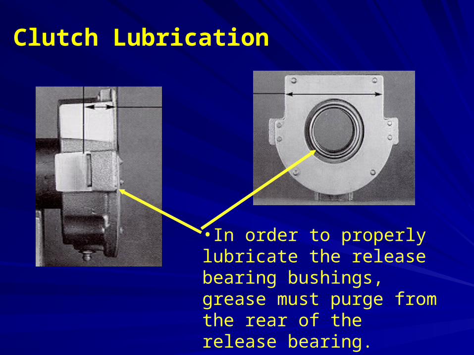
•In order to properly lubricate the release bearing bushings, grease must purge from the rear of the release bearing.

Spicer Solo Product FamilySpicer Solo Product Family
15.5” HD Eaton Spicer Solo
14” MD Eaton Spicer Solo

Spicer Solo Heavy-DutySpicer Solo Heavy-Duty

Spicer Solo Medium-DutySpicer Solo Medium-Duty
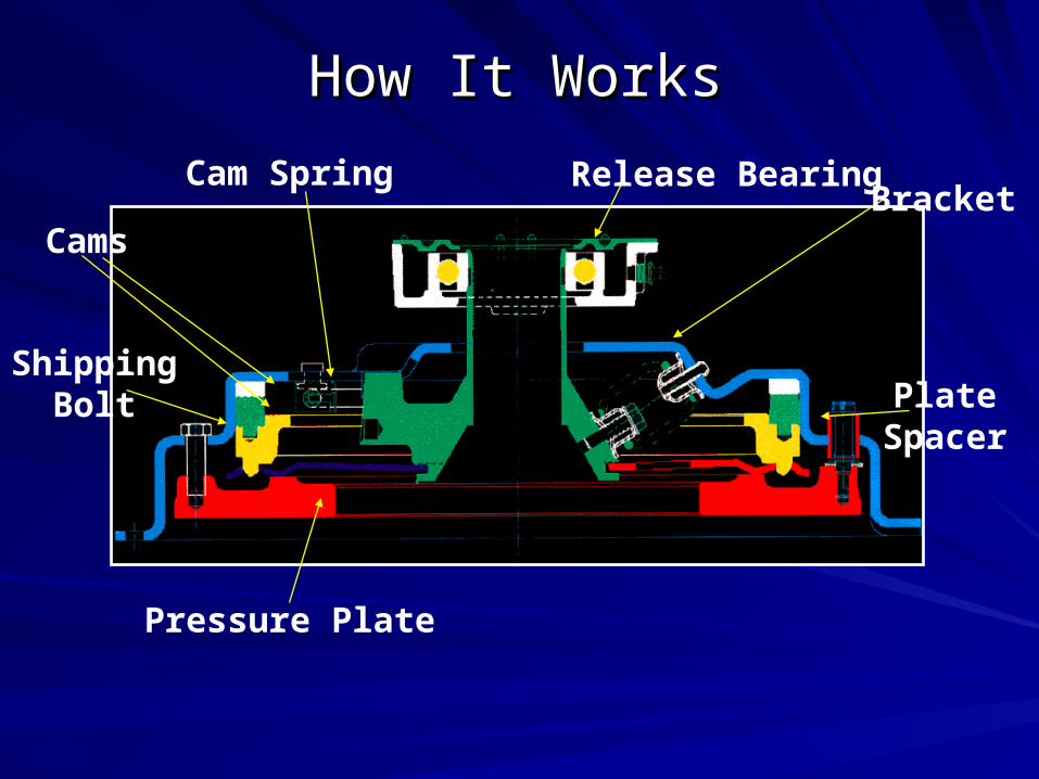
How It WorksHow It Works
Pressure Plate
BracketRelease Bearing
ShippingBolt Plate
Spacer
Cam Spring
Cams
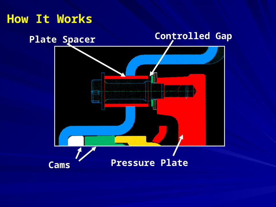
Plate Spacer Controlled Gap
Cams Pressure Plate
How It Works

Wear IndicatorWear Indicator
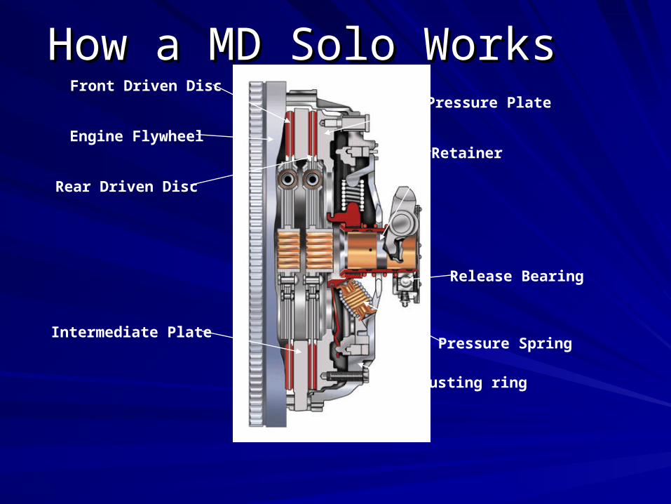
How a MD Solo WorksHow a MD Solo WorksFront Driven Disc
Engine Flywheel
Rear Driven Disc
Intermediate Plate
Adjusting ring
Pressure Spring
Release Bearing
Retainer
Pressure Plate
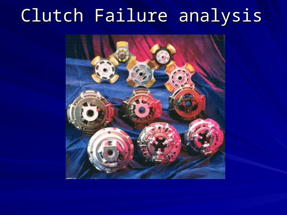
Clutch Failure analysisClutch Failure analysis
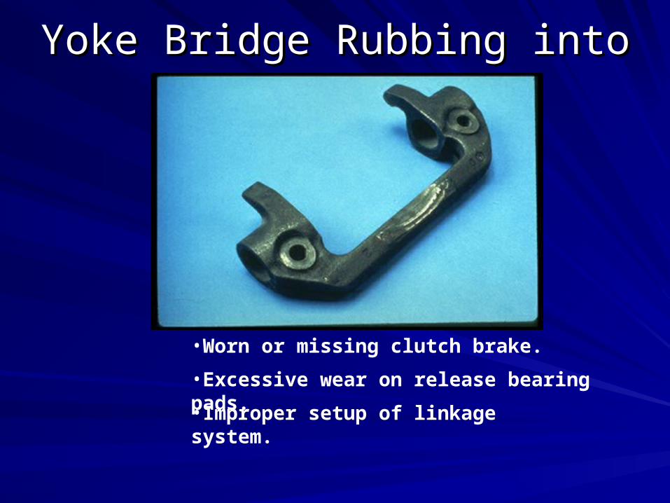
Yoke Bridge Rubbing into CoverYoke Bridge Rubbing into Cover
•Worn or missing clutch brake.
•Excessive wear on release bearing pads.
•Improper setup of linkage system.
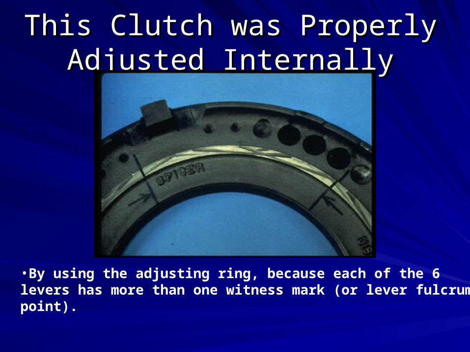
This Clutch was Properly This Clutch was Properly Adjusted InternallyAdjusted Internally
•By using the adjusting ring, because each of the 6 levers has more than one witness mark (or lever fulcrum point).

Bent/Broken Kwik-Adjust Bent/Broken Kwik-Adjust MechanismMechanism
•From not releasing the load from the pressure plate before making an adjustment.
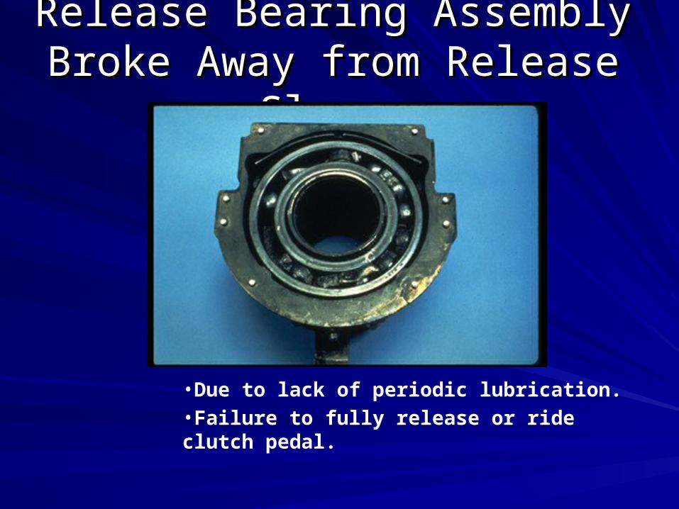
Release Bearing Assembly Release Bearing Assembly Broke Away from Release Broke Away from Release
SleeveSleeve
•Due to lack of periodic lubrication.•Failure to fully release or ride clutch pedal.
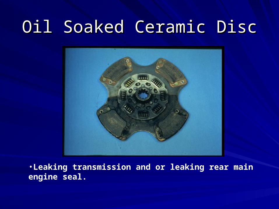
Oil Soaked Ceramic DiscOil Soaked Ceramic Disc
•Leaking transmission and or leaking rear main engine seal.
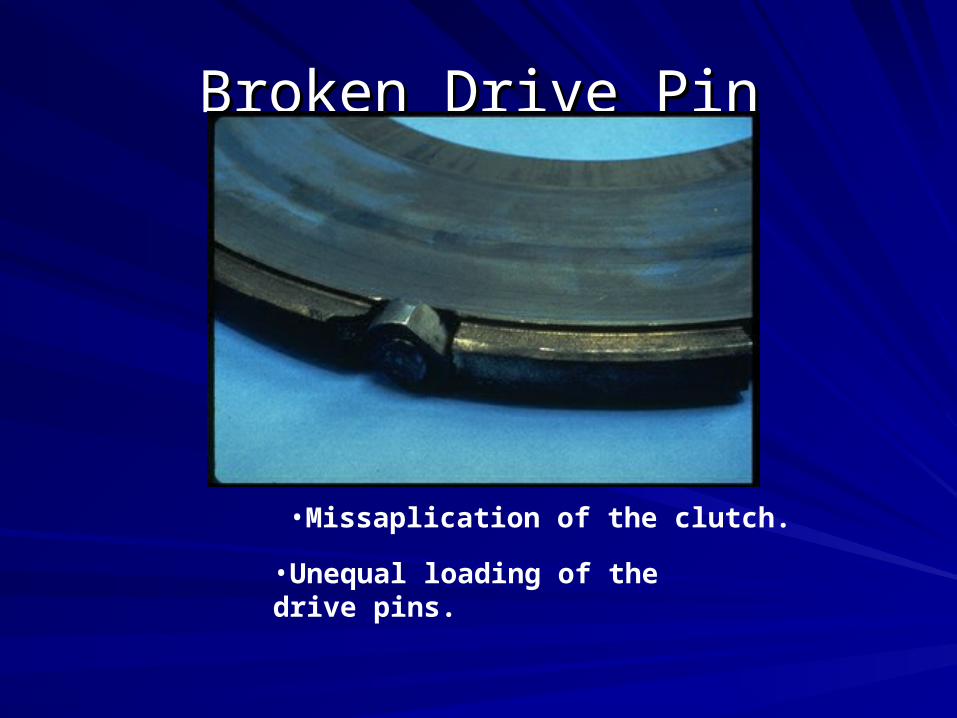
Broken Drive PinBroken Drive Pin
•Missaplication of the clutch.
•Unequal loading of the drive pins.
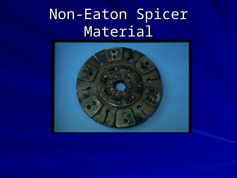
Non-Eaton Spicer MaterialNon-Eaton Spicer Material

Input Shaft (drive gear) Spline Input Shaft (drive gear) Spline WearWear
•Engine torsionals/vibration.

Rear Disc Interfering with the Rear Disc Interfering with the Retainer AssemblyRetainer Assembly
•Adjusting the clutch externally with the linkage.
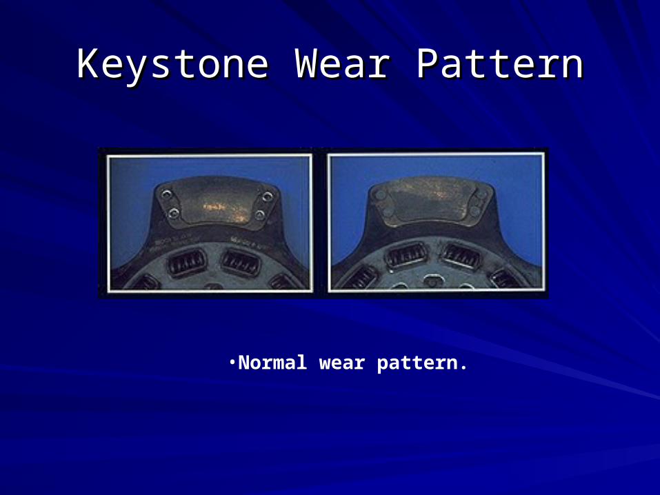
Keystone Wear PatternKeystone Wear Pattern
•Normal wear pattern.

Grease on Buttons of Ceramic Grease on Buttons of Ceramic DiscsDiscs
•Failure to remove rust preventative from the flywheel.•Greasing the splined areas of either the input shaft or disk.
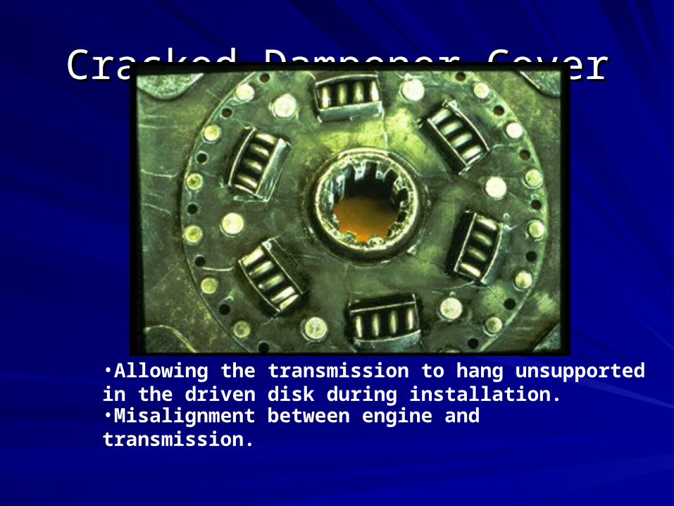
Cracked Dampener CoverCracked Dampener Cover
•Allowing the transmission to hang unsupported in the driven disk during installation.•Misalignment between engine and transmission.