Cluster Secondary Ion Mass Spectrometry Of Polmyers and Related ...
47
CLUSTER SECONDARY ION MASS SPECTROMETRY OF POLYMERS AND RELATED MATERIALS Christine M. Mahoney* Chemical Science and Technology Laboratory, Surface and Microanalysis Science Division, National Institute of Standards and Technology, 100 Bureau Drive, Mail Stop 8371, Gaithersburg, MD 20899-8371 Received 10 September 2008; received (revised) 22 January 2009; accepted 22 January 2009 Published online in Wiley InterScience (www.interscience.wiley.com) DOI 10.1002/mas.20233 Cluster secondary ion mass spectrometry (cluster SIMS) has played a critical role in the characterization of polymeric materials over the last decade, allowing for the ability to obtain spatially resolved surface and in-depth molecular information from many polymer systems. With the advent of new molecular sources such as C þ 60 , Au þ 3 , SF þ 5 , and Bi þ 3 , there are considerable increases in secondary ion signal as compared to more conventional atomic beams (Ar þ , Cs þ , or Ga þ ). In addition, compositional depth profiling in organic and polymeric systems is now feasible, without the rapid signal decay that is typically observed under atomic bombardment. The premise behind the success of cluster SIMS is that compared to atomic beams, polyatomic beams tend to cause surface-localized damage with rapid sputter removal rates, resulting in a system at equilibrium, where the damage created is rapidly removed before it can accumulate. Though this may be partly true, there are actually much more complex chemistries occurring under polyatomic bombardment of organic and polymeric materials, which need to be considered and discussed to better understand and define the important parameters for successful depth profiling. The following presents a review of the current literature on polymer analysis using cluster beams. This review will focus on the surface and in-depth characterization of polymer samples with cluster sources, but will also discuss the characterization of other relevant organic materials, and basic polymer radiation chemistry. # 2009 Wiley Periodicals, Inc., { Mass Spec Rev Keywords: SIMS; polymers; mass spectrometry; cluster; depth profiling; C 60 ; Bi; SF 5 I. INTRODUCTION Secondary ion mass spectrometry (SIMS) is a mass spectro- metric-based analytical technique, which is used to obtain information about the molecular, elemental and isotopic composition of a surface. In a conventional SIMS experiment, an energetic primary ion beam, such as Ga þ , Cs þ , or Ar þ is focused onto a solid sample surface under ultra-high vacuum conditions. The interaction of the primary ion beam with the sample results in the desorption of secondary ions from the surface of the material, which are subsequently extracted into a mass spectrometer. Though this technique has been widely employed for the characterization of inorganic materials, wide- spread use of SIMS for analysis of organic systems has been historically limited by low secondary ion yields and beam- induced damage effects that result from the use of atomic primary ion beams. Organic materials typically require the use of ‘‘static SIMS’’ analysis conditions where the primary ion fluence is maintained below a critical dose to retain the surface in an undamaged state, resulting in decreased sensitivity and preclud- ing compositional depth profiling. This critical dose is defined as the ‘‘static limit,’’ and is often reported to be at or below 1 10 13 ions/cm 2 , depending on the sample and the ion beam employed. One potential solution to this limitation is to use cluster or polyatomic primary ion bombardment. When a cluster ion impacts a surface, the cluster breaks apart and each atom in the cluster retains only a fraction of the initial energy of the ion, thus resulting in a significant reduction in penetration depth of the ion (since penetration depth is propor- tional to impact energy) (Gillen & Roberson, 1998). This causes surface-localized damage and consequently, preserves the chemical structure in the subsurface region (see Fig. 1). Atomic beams however, will penetrate deeply, resulting in the breaking of molecular bonds deep into the sample and thus precluding the ability to depth profile in molecular samples. Furthermore, because there are more atoms bombarding the sample simulta- neously with cluster ions, the sputtering yield can be significantly enhanced. This is in part because of the increased number of atoms per ion, but is also a result of the formation of a high energy density ‘‘collisional spike’’ regime which is formed with cluster ion bombardment (Sigmund & Claussen, 1981), causing non- linear sputtering yield enhancements (i.e., sputtering yield of C þ n nC þ ). The benefits of utilizing cluster sources was shown as early as 1960, with the observation of non-linear enhancements in sputtering yields when using cluster beams (Gronlund & Moore, 1960; Andersen & Bay, 1974, 1975; Thompson & Johar, 1979). However, cluster sources were not employed for SIMS applications until the mid to late 1980s. One of the earliest works was published in 1982, in which the authors compared the performance of siloxane molecular ions to Hg þ ions for characterization of oligosaccharides in a glycerol matrix (Wong, Mass Spectrometry Reviews ß Wiley Periodicals, Inc. { This article is a US Government work and, as such, is in the public domain in the United States of America. ———— *Correspondence to: Christine M. Mahoney, Chemical Science and Technology Laboratory, Surface and Microanalysis Science Division, National Institute of Standards and Technology, 100 Bureau Drive, Mail Stop 8371, Gaithersburg, MD 20899-8371. E-mail: [email protected]
Transcript of Cluster Secondary Ion Mass Spectrometry Of Polmyers and Related ...

CLUSTER SECONDARY ION MASS SPECTROMETRY OFPOLYMERS AND RELATED MATERIALS
Christine M. Mahoney*Chemical Science and Technology Laboratory, Surface and MicroanalysisScience Division, National Institute of Standards and Technology,100 Bureau Drive, Mail Stop 8371, Gaithersburg, MD 20899-8371
Received 10 September 2008; received (revised) 22 January 2009; accepted 22 January 2009
Published online in Wiley InterScience (www.interscience.wiley.com) DOI 10.1002/mas.20233
Cluster secondary ion mass spectrometry (cluster SIMS) hasplayed a critical role in the characterization of polymericmaterials over the last decade, allowing for the ability to obtainspatially resolved surface and in-depth molecular informationfrom many polymer systems. With the advent of new molecularsources such as Cþ
60, Auþ3 , SF
þ5 , and Bi
þ3 , there are considerable
increases in secondary ion signal as compared to moreconventional atomic beams (Arþ, Csþ, or Gaþ). In addition,compositional depth profiling in organic and polymeric systemsis now feasible, without the rapid signal decay that is typicallyobserved under atomic bombardment. The premise behind thesuccess of cluster SIMS is that compared to atomic beams,polyatomic beams tend to cause surface-localized damage withrapid sputter removal rates, resulting in a system atequilibrium, where the damage created is rapidly removedbefore it can accumulate. Though this may be partly true, thereare actually much more complex chemistries occurring underpolyatomic bombardment of organic and polymeric materials,which need to be considered and discussed to better understandand define the important parameters for successful depthprofiling. The following presents a review of the currentliterature on polymer analysis using cluster beams. This reviewwill focus on the surface and in-depth characterization ofpolymer samples with cluster sources, but will also discuss thecharacterization of other relevant organic materials, and basicpolymer radiation chemistry. # 2009 Wiley Periodicals, Inc.,{
Mass Spec RevKeywords: SIMS; polymers; mass spectrometry; cluster; depthprofiling; C60; Bi; SF5
I. INTRODUCTION
Secondary ion mass spectrometry (SIMS) is a mass spectro-metric-based analytical technique, which is used to obtaininformation about the molecular, elemental and isotopiccomposition of a surface. In a conventional SIMS experiment,an energetic primary ion beam, such as Gaþ, Csþ, or Arþ is
focused onto a solid sample surface under ultra-high vacuumconditions. The interaction of the primary ion beam with thesample results in the desorption of secondary ions from thesurface of the material, which are subsequently extracted into amass spectrometer. Though this technique has been widelyemployed for the characterization of inorganic materials, wide-spread use of SIMS for analysis of organic systems has beenhistorically limited by low secondary ion yields and beam-induced damage effects that result from the use of atomic primaryion beams. Organic materials typically require the use of ‘‘staticSIMS’’ analysis conditions where the primary ion fluence ismaintained below a critical dose to retain the surface in anundamaged state, resulting in decreased sensitivity and preclud-ing compositional depth profiling. This critical dose is definedas the ‘‘static limit,’’ and is often reported to be at or below1� 1013 ions/cm2, depending on the sample and the ion beamemployed. One potential solution to this limitation is to usecluster or polyatomic primary ion bombardment.
When a cluster ion impacts a surface, the cluster breaks apartand each atom in the cluster retains only a fraction of the initialenergy of the ion, thus resulting in a significant reduction inpenetration depth of the ion (since penetration depth is propor-tional to impact energy) (Gillen & Roberson, 1998). This causessurface-localized damage and consequently, preserves thechemical structure in the subsurface region (see Fig. 1). Atomicbeams however, will penetrate deeply, resulting in the breaking ofmolecular bonds deep into the sample and thus precluding theability to depth profile in molecular samples. Furthermore,because there are more atoms bombarding the sample simulta-neously with cluster ions, the sputtering yield can be significantlyenhanced. This is in part because of the increased number ofatoms per ion, but is also a result of the formation of a high energydensity ‘‘collisional spike’’ regime which is formed with clusterion bombardment (Sigmund & Claussen, 1981), causing non-linear sputtering yield enhancements (i.e., sputtering yield ofCþ
n � nCþ).The benefits of utilizing cluster sources was shown as early
as 1960, with the observation of non-linear enhancementsin sputtering yields when using cluster beams (Gronlund &Moore, 1960; Andersen & Bay, 1974, 1975; Thompson & Johar,1979). However, cluster sources were not employed for SIMSapplications until the mid to late 1980s. One of the earliest workswas published in 1982, in which the authors comparedthe performance of siloxane molecular ions to Hgþ ions forcharacterization of oligosaccharides in a glycerol matrix (Wong,
Mass Spectrometry Reviews� Wiley Periodicals, Inc. {This article is a US Government work and, as such,is in the public domain in the United States of America.
————*Correspondence to: Christine M. Mahoney, Chemical Science and
Technology Laboratory, Surface and Microanalysis Science Division,
National Institute of Standards and Technology, 100 Bureau Drive,
Mail Stop 8371, Gaithersburg, MD 20899-8371.
E-mail: [email protected]

Stoll, & Rollgen, 1982). The results showed a large increase inthe ionization of the organic molecules when employing thesiloxane cluster source as compared to the atomic Hgþ ionsource.
Later, Appelhans and Delmore (1987) used SF6 neutralbeams to characterize electrically insulating polymer samplessuch as poly(tetrafluoroethylene) (PTFE), poly(ethylenetereph-thalate) (PET), poly(methylmethacrylate) (PMMA) and poly-phosphazene, where the authors found that the SF6 cluster beamyielded three to four orders of magnitude more intense secondaryion yields from these polymer samples than equivalent energyatomic beams. Similar findings were found in the mass spectra ofpharmaceutical compounds (Appelhans & Delmore, 1989).
Cornett and co-workers (Cornett, Lee, & Mahoney, 1994)demonstrated that continued bombardment of protein sampleswith massive glycerol cluster ions yielded constant molecularsecondary ion signals with increasing fluence, while the samesamples irradiated with Xeþ ions yielded the characteristic rapidsignal decay that is commonly associated with atomic beams.This indicated that depth profiling (analysis of composition withincreasing depth into the sample, via sputter removal) in organicmaterials was feasible.
The first demonstration of a polymer depth profile waspublished a few years later by Gillen and co-workers (Gillen &Roberson, 1998), who used a polyatomic SFþ
5 source to profilethrough a thin layer of PMMA on Si. Since then, there has been anabundance of work on depth profiling and surface character-ization in polymeric materials with cluster beams. Clusterprimary ion sources such as Cþ
60, C�8 , Auþ3 , SFþ
5 , and Biþ3 , havealready generated considerable interest for organic and poly-meric SIMS applications, where they have resulted in significantimprovements (typically >1,000-fold) in characteristic molec-ular secondary ion yields and decreased beam-induced, sub-surface damage. The surface-localized damage characteristicof cluster sources, coupled with increased sputter removal rates,has led to the ability to depth profile through many organic andpolymeric materials without the rapid signal decay typicallyobserved with atomic primary ion sources. With the increased
sensitivity, nanoscale depth resolution (�10 nm) and sub-micrometer lateral resolution, cluster SIMS is a promising newcharacterization tool enabling high-resolution three-dimensionalimaging capabilities for organic and polymeric-based materials.
This review will focus on the characterization of polymericsamples with cluster sources, but will discuss characterization ofother relevant organic materials as well as the basic chemistry ofpolymer irradiation. For more information regarding clusterSIMS fundamentals, molecular dynamics simulations andmolecular and biological materials characterization with clusterbeams, see the following review articles (Le Beyec, 1998;Brunelle, Touboul, & Laprevote, 2005; Winograd, 2005;Wucher, 2006; Garrison & Postawa, 2008).
II. THEORY
A. Molecular Dynamics Simulations
Comprehensive studies of molecular dynamics (MD) simulationshave been performed to better understand the bombardment ofsurfaces by atomic versus polyatomic primary ion bombardment.Figure 2 compares molecular dynamics simulations of both15 keV C60 and 15 keV Ga projectiles impinging onto a Agsurface (Postawa et al., 2003, 2004). Note the large amount ofinterlayer mixing that occurs with the Gaþ probe. Also note thatthere is very little material removed from the surface resultingfrom the Gaþ impact. The MD simulations of the Cþ
60 impacthowever, show a much greater amount of material being removedfrom the surface, with very little damage to the underlying layers.In other words, the damaged area created by the Cþ
60 is almostcompletely removed and does not accumulate.
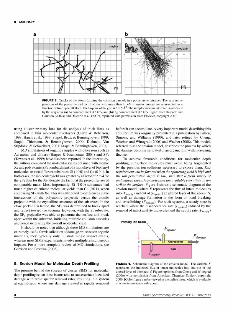
Molecular dynamics simulations of organic and polymericsamples have yielded similar results. Delcorte and co-workers,have been active in the modeling of both atomic and polyatomicbombardment of polymer samples such as polystyrene (PS)(Delcorte & Garrison, 2000, 2007; Delcorte, 2005; Delcorte,Poleunis, & Bertrand, 2006a; Delcorte et al., 2007) and PET(Delcorte et al., 1999). An interesting example is shown inFigure 3, which shows the simulation of projectile damagecreated in PS tetramer samples with 5 keV C60 as compared to5 keVAr. Similar to what was observed with ion bombardment onAg substrates, the Ar ion was found to penetrate much farther intothe PS matrix than the C60 ion (Delcorte & Garrison, 2007;Delcorte et al., 2007). The Ar ion therefore caused several bond-scissions and a cascade of collisions extending into the depth ofthe sample, causing extensive subsurface damage. Furthermore,it was determined that very few branches of the cascade wereupward directed, resulting in very low molecular yields with Arprojetiles. In comparison, the damage created by the C60
projectile remained in the top 2 nm of the PS target. The damagewas therefore confined to a much smaller volume, closer to thesurface, and with a very high energy density. This ultimatelyresulted in significant enhancements in the calculated molecularyield with corresponding decreases in subsurface damage.
Czerwinski et al. (2006) and Postawa et al. (2005) comparedGa and C60 ion bombardment on thin organic overlayers of PStetramers (monolayer) and benzene (three layers) deposited onto
FIGURE 1. Graphic illustration suggesting how high sputter yields and
low penetration depths observed with polyatomic bombardment reduces
the accumulation of beam-induced damage in an organic thin film.
(SY, sputter yield; and Range, penetration depth of ion(s).) Figure from
Gillen and Roberson (1998) reprinted with permission from John Wiley
& Sons, Ltd, copyright 1998.
& MAHONEY
2 Mass Spectrometry Reviews DOI 10.1002/mas

Ag substrates. The results outlined major differences in thesputter mechanisms between the two ion beams. As opposed toGa, which induces the typical collision cascade regime whenbombarding the surface, eventually resulting in the ejection oforganic molecules uplifted by departing substrate atoms, the C60
invoked a more collective large-scale process where theindividual atoms in the C60 work cooperatively to move the Agatoms rather than behaving as individual atoms initiating theirown collision cascades. The result is a shockwave in the Ag,whereby intact molecules are ejected by a concerted action of
substrate atoms involved in the unfolding of the crater (describedas a ‘‘catapulting mechanism’’). The conclusion from this workwas that for thin organic overlayers, approaching monolayercoverage, there is very little gain in the application of thepolyatomic projectiles because although emission of thesubstrate particles is significantly enhanced with the C60, therewas little or no enhancement of the ejection of intact molecules.Furthermore, there was significant fragmentation of the ejectedspecies when employing C60. This is consistent with exper-imental evidence indicating that there is a greater benefit when
FIGURE 2. Cross-sectional view of the temporal evolution of a typical collision event leading to ejection of
atoms due to 15 keV Ga and C60 bombardment of a Ag{1 1 1} surface at normal incidence. The atoms are
colored by original layers in the substrate. The projectile atoms are black. Figure reprinted from Postawa
et al. (2004) with permission from American Chemical Society, copyright 2004. [Color figure can be viewed
in the online issue, which is available at www.interscience.wiley.com.]
CLUSTER SECONDARY ION MASS SPECTROMETRY &
Mass Spectrometry Reviews DOI 10.1002/mas 3
using cluster primary ions for the analysis of thick films ascompared to thin molecular overlayers (Gillen & Roberson,1998; Harris et al., 1999; Stapel, Brox, & Benninghoven, 1999;Stapel, Thiemann, & Benninghoven, 2000; Diehnelt, VanStipdonk, & Schweikert, 2001; Stapel & Benninghoven, 2001).
MD simulations of organic samples with other ions such asAu atoms and dimers (Harper & Krantzman, 2004) and SF5
(Townes et al., 1999) have also been reported. In the latter study,the authors compared the molecular yields obtained with atomicXe and polyatomic SF5 bombardment of a monolayer of biphenylmolecules on two different substrates, Si (1 0 0) and Cu (0 0 1). Inboth cases, the molecular yield was greater by a factor of 2 to 4 forthe SF5 than for the Xe, despite the fact that the projectiles are ofcomparable mass. Most importantly, Si (1 0 0) substrates hadmuch higher calculated molecular yields than Cu (0 0 1), whencomparing SF5 with Xe. This was attributed to differences in theinteractions of the polyatomic projectile versus the atomicprojectile with the crystalline structures of the substrates. In theclose packed Cu lattice, the SF5 was determined to break apartand reflect toward the vacuum. However, with the Si substrate,the SF5 projectile was able to penetrate the surface and breakapart within the substrate, initiating multiple collision cascadesand hence increasing the overall molecular yield.
It should be noted that although these MD simulations areextremely useful for visualization of damage processes in organicmaterials, they typically only illustrate single impact events,whereas most SIMS experiments involve multiple, simultaneousimpacts. For a more complete review of MD simulations, seeGarrison and Postawa (2008).
B. Erosion Model for Molecular Depth Profiling
The premise behind the success of cluster SIMS for moleculardepth profiling is that these beams tend to cause surface-localizeddamage with rapid sputter removal rates, resulting in a systemat equilibrium, where any damage created is rapidly removed
before it can accumulate. Avery important model describing thisequilibrium was originally presented in a publication by Gillen,Simons, and Williams (1990), and later refined by Cheng,Wucher, and Winograd (2006) and Wucher (2008). This model,referred to as the erosion model, describes the process by whichthe damage becomes saturated in an organic film with increasingfluence.
To achieve favorable conditions for molecular depthprofiling, subsurface molecules must avoid being fragmentedby the previous ion collisions necessary to expose them. Thisrequirement will be favored when the sputtering yield is high andthe ion penetration depth is low, such that a fresh supply ofundamaged subsurfacemolecules are available every time an ionstrikes the surface. Figure 4 shows a schematic diagram of theerosion model, where F represents the flux of intact moleculesinto (Fsupply) and out of (Fsputter) an altered layer of thickness (d),as well as damage formation in the form of bond breakingand crosslinking (Fdamage). For such systems, a steady state isreached, where the disappearance rate (Fsputter) induced by theremoval of intact analyte molecules and the supply rate (Fsupply)
FIGURE 3. Tracks of the atoms forming the collision cascade in a polystyrene tetramer. The successive
positions of the projectile and recoil atoms with more than 10 eV of kinetic energy are represented as a
function of time up to 200 fsec. Each square of the grid is 5� 5 A2. The sample-vacuum interface is indicated
by the gray area. (a) Ar bombardment at 5 keV, and (b) C60 bombardment at 5 keV. Figure from Delcorte and
Garrison (2007a) and Delcorte et al. (2007), reprinted with permission from Elsevier, copyright 2007.
FIGURE 4. Schematic diagram of the erosion model. The variable F
represents the indicated flux of intact molecules into and out of the
altered layer of thickness d. Figure reprinted from Cheng and Winograd
(2006) with permission from American Chemical Society, copyright
2006. [Color figure can be viewed in the online issue, which is available
at www.interscience.wiley.com.]
& MAHONEY
4 Mass Spectrometry Reviews DOI 10.1002/mas

or recovery of undamaged molecules through surface erosion,reach an equilibrium, and no further damage is accumulated.
This damage saturation was predicted by Gillen, Simons,and Williams (1990) to occur at a fluence inversely proportionalto the sputtering yield as follows in Equation (1): where d is thedepth into the sample that is altered by ion beam interactions, Rd
is the mean depth of the damage distribution curve, Q¼ fluencerequired for removal of depth d, and n/Y is the density ofmolecules divided by the molecular yield of the compound.
Q ¼ dn
Y¼ 2Rd
n
Yð1Þ
This model was able to predict both the location and themeasured signal intensity drop in the surface transient region in asample of methylene chloride (within a factor of 2) (Gillen,Simons, & Williams, 1990).
The model was further modified by Cheng and co-workers(Cheng & Winograd, 2006) to describe the molecular signalintensity as a function of Cþ
60 fluence in trehalose systems, and itwas found that the model provided a good fit to the experimentaldata (see Eq. 2):
Sðf Þ ¼ Sss þ ðS0 � SssÞ exp � Y
nd
� �þ sd
� �f
� �ð2Þ
where S0 is the signal intensity at zero fluence, Sss is the signalintensity at steady state (damage saturation region), f is the ionfluence, and sd is the damage cross section associated with theorganic material of interest.
The term [�(Y/nd)þsd] in Equation (2) is defined as thedisappearance cross section (see Appendix) where Y/nd istermed, the ‘‘clean-up efficiency’’. Hence if the sputter rate ishigh, it is expected that the cleanup efficiency will contributemost to the signal decay, while if sputter rate is low and damage ishigh, the damage cross section will contribute most to the signaldecay.
Equation (2) describes the initial exponential decayobserved SIMS depth profiles, later referred to as region I, butdoes not describe any further decline in signal in the steady stateregion (region II). This region is discussed in greater detail inmore recent work by Wucher (2008). Unlike the case described inEquation (2), which assumes a constant erosion rate withincreasing fluence in the steady steady state region, thismodification describes the case where the erosion rate, or sputteryield (Y), changes with fluence. For the case of a slowly varyingsputter yield, a quasi-steady state approximation can be used todescribe the signal variation after the initial exponential decay.The fluence-dependent erosion rate model provided a good fit tothe experimental data as illustrated in Figure 5.
It should be noted, that the erosion dynamics modeldescribed here was developed for molecular depth profiling inorganic films, and does not apply strictly to polymer depthprofiling. This is because in the case of polymeric depth profiling,one measures the intensities of characteristic fragments of themolecule, not the molecular ion itself, and therefore it is likely toexhibit very different disappearance cross sections. However, thismodel is still very relevant in terms of the general underlyingdamage processes occurring during sputtering of polymers andthe resulting polymer depth profile shapes that are typicallyobserved.
III. AVAILABLE CLUSTER SOURCES1
A. SFþ5
The SFþ5 source is an electron impact design, where SF6 gas is
leaked into an ionization chamber and bombarded with electronssuch that SFþ
n ions are created, where n¼ 1–5, and n¼ 5 is themost abundant. Prior to the development of SFþ
5 , Appelhans andDelmore developed a neutral SF6 ion beam system, in one ofthe earliest works of organic analysis with a cluster source(Appelhans & Delmore, 1987; 1989), illustrating significantsignal enhancements and decreased charging when employingthese beams as opposed to atomic beams for organic character-ization. Since neutral beams are extremely difficult to focus,Hand et al. utilized charged SFþ
5 ions and compared the massspectra of several organic salts to those obtained with otherpolyatomic ions including Nþ
2 COþ2 and CFþ
3 (Hand, Majumdar,& Cooks, 1990). The authors noted that the highest efficiencieswere obtained for SFþ
5 , though at the cost of increasedfragmentation as compared to the other beams.
These sources were developed commercially for time-of-flight (TOF)-based static SIMS instruments (Kotter & Benning-hoven, 1998; Stapel, Brox, & Benninghoven, 1999; Stapel,Thiemann, & Benninghoven, 2000; Stapel & Benninghoven,
FIGURE 5. Measured (M–OH)þ molecular ion signal as a function of
projectile fluence for a 350-nm cholesterol film on Si, analyzed by 40-
keV Cþ60 projectile ions. The solid line denotes the signal variation as
predicted by the erosion model, assuming a linear erosion rate variation
in the steady state region. See reference for detailed fitting parameters.
Figure reprinted from Wucher (2008) with permission from Wiley-
Blackwell, copyright 2008. [Color figure can be viewed in the online
issue, which is available at www.interscience.wiley.com.]
————1Commercial equipment and materials are identified in order to
adequately specify certain procedures. In no case does such
identification imply recommendation or endorsement by the National
Institute of Standards and Technology, nor does it imply that the
materials or equipment identified are necessarily the best available for
the purpose.
CLUSTER SECONDARY ION MASS SPECTROMETRY &
Mass Spectrometry Reviews DOI 10.1002/mas 5

2001). Gillen and co-workers also developed an SFþ5 source for
magnetic sector SIMS instruments (Gillen & Roberson, 1998;Gillen, King, & Chmara, 1999).
B. Cþ60 and Other C-Based Sources
Since the introduction of cluster SIMS, there have been manycarbon-based sources, including massive glycerol clusters(Mahoney et al., 1991), coronene and coronene dimers (C24H12
and (C24H12)2) (Blain et al., 1989; Boussofiane-Baudin et al.,1994; Biddulph et al., 2007), phenylalanine (C9H11NO2) probes(Blain et al., 1989), Cþ
n (Salehpour, Fishel, & Hunt, 1988a), C�n
(Gillen et al., 2001), CxHþy , and CxF
þy (Salehpour, Fishel, & Hunt,
1988a,b; Stapel, Brox, & Benninghoven, 1999). C60 wasintroduced as a source for SIMS applications in 1994(Boussofiane-Baudin et al., 1994), where the authors comparedmolecular projectiles of Auþn , coronene and coronene dimers,C37, C60, and C70 in the characterization of various Langmuir–Blodgett (LB) films and phenylalanine films. For all cases studiedin this work, the organic cluster ions containing C as opposed togold had much larger molecular ion yields and increasing beamenergies resulted in linear increases in these ion yields. The firstcommercially available C60 source was introduced in 2003(Wong et al., 2003; Weibel et al., 2003; Hill et al., 2006). It isdescribed as a thermal effusive source, where C60 powder isheated and evaporated at >4008C, and then is subsequentlyionized by electron bombardment. This source is currently one ofthe most highly utilized cluster sources for organic depthprofiling applications.
C. Auþn Clusters
The Au cluster source is a liquid metal ion gun (LMIG) design,similar to a Ga source, but is able to generate Au clusters (Auþ
n ,where n¼ 1–3). Benguerba et al. (1991) were among the firstscientists to employ a liquid metal ion source for the productionof Auþ
n clusters. The authors used this source for characterizationof phenylalanine samples and saw a significant increase in signalintensity characteristic of the molecular ion yield, albeit withcorresponding increases in fragmentation. Later (1998), Ander-sen studied non-linear effects with Auþ1 to Auþ5 clusters(Andersen et al., 1998). The first commercially available Aucluster source was finally introduced in 2003 (Davies et al.,2003). Because of the LMIG design, Au (and Bi) sources haveextremely high spatial resolutions (�100 nm), with Au trimershaving much improved useful lateral resolutions (Dl) ascompared to the atomic beams (Kollmer, 2004). The usefullateral resolution is defined below as:
Dl ¼ N
E
� �1=2
¼ NsY
� �1=2
ð3Þ
where N is the number of secondary ions detected from the areaDl2 (Kollmer, 2004), s is the disappearance cross section of thematerial, Y is the secondary ion yield and E is the secondary ionformation efficiency (see Appendix). Kollmer (2004) hasreported useful lateral resolutions of 1,300 nm for Gaþ, 400 nmfor Auþ and Biþ and 150 nm for Auþ3 and Biþ3 for a sample oforganic pigments on a color filter array.
D. Biþn Clusters
Bi has been explored as a potential ion source for sputtering asearly as 1979, when Thompson and Johar worked with Biþnclusters and other sources to study non-linear effects (Thompson& Johar, 1979). However, Bi was not used for SIMS applicationsuntil after the development of the Au cluster source. The Bisource, whose design is similar to that of the Au source, wasintroduced as a commercially available source in 2004 (Kollmer,2004). The Bi source was found to be beneficial because ascompared to Au, Bi emitted larger clusters (Biþn , where n¼ 1–7)and produced higher currents of those clusters. Moreover,bismuth was found to emit a variety of doubly charged clusters.As compared to Au imaging, Bi was found to result in moreintense molecular ion images with comparable lateral resolutions(Kollmer, 2004).
E. Massive Au Clusters
Au4þ400 cluster ions were first introduced by Tempez et al. (2004)
where the authors used both small and large gold clusters tocharacterize peptide samples. It was demonstrated in this workthat there were significant signal enhancements as well asdecreased damage cross sections when using the Au4þ
400 ascompared to Auþ5 and Auþ9 ions, making it potentially useful fordepth profiling applications. In addition, Au4þ
400 ions are known tofurther enhance the signal by creating Au-analyte adducts, whichare not observed with smaller gold clusters such as Auþ
5 (Hageret al., 2006).
This source was further developed by Schweikert et al. forsingle impact events, where instead of a focused beam of ions, asingle Au4þ
400 primary ion projectile impacts the surface and theresulting secondary ions are recognized as singular events(Guillermier et al., 2006a; Verkjoturov et al., 2006). Though thissource is not yet designed for imaging experiments, (currently itcan not be determined where the beam is actually sampling) thistype of source may have major implications for imaging in thefuture, as the spatial resolution will only be limited by the lateralextent of the surface area influenced by the single impact event,and not the focusing elements of the source.
It should be noted that the basic design of this source wasactually developed earlier (Van Stipdonk, Harris, & Schweikert,1996) for Cþ
60, (CsI)nCsþ, and Gaþ beams, in the event-by-eventbombardment and detection mode to investigate the secondaryion yields of CsI and phenylalanine molecules. The single impactCþ
60 source was further used by Locklear et al. (2006) tocharacterize matrices in cluster SIMS, and also by Verkhoturov,who used both Cþ
60 and Au4þ400 to characterize glycine samples
(Verkjoturov et al., 2006). It was found that the Au4þ400 projectile
induced abundant multi-ion emission (e.g., the average numberof detected ions emitted per event from glycine was 12.5, muchlarger than was observed with Cþ
60) (Verkjoturov et al., 2006).
F. Gas Cluster Beams
Gas cluster ion beams consist of hundreds to thousands of atomsor molecules of gaseous materials. The individual gas atoms arefirst condensed into neutral clusters, generated through cooling in
& MAHONEY
6 Mass Spectrometry Reviews DOI 10.1002/mas

a supersonic expansion. These neutral clusters of varying size aresubsequently ionized by electron bombardment, and accelerated.The chemistry of these beams is variable and can be comprised ofAr, O2, CO2, or SF6 gases, to name a few. These large gas clustersare used mainly for modification of surfaces (growth of well-controlled oxide layers, cluster ion implantation, smoothing ofsurfaces, cleaning of surfaces, etc.). Not surprisingly, thesputtering yields were found to be much higher for the gasclusters as opposed to the corresponding monomers, and reactivegas clusters, such as O2 and SF6 clusters, result in the largestsputtering yields. A very good review of the work done on gascluster beams was written by Yamada et al. (2001). Morerecently, a SIMS system employing these gas cluster sources wasdeveloped, employing an Ar2000 ion beam source (Matsuo et al.,2004, 2008; Ninomiya et al., 2006; Ichiki et al., 2008; Nakataet al., 2008). These sources have a lot of promise in the field ofpolymer depth profiling in particular.
G. Other Beams
Ionic projectiles such as CsIþ, Cs2Iþ, and Cs3Iþ2 have been usedextensively in the past (Blain et al., 1989). Diehnelt also utilizedand compared the performance of several of these ionic clustersources including (CsI)Csþ, (CsI2)Csþ, (NaF)Naþ, (NaF)2Naþ,(NaF)4Naþ, and SiF�
5 (Harris et al., 1999; Diehnelt, VanStipdonk, & Schweikert, 2001) for characterization of organicoverlayers. Other examples of cluster sources that have beendiscussed in the literature include CFþ
3 (Reuter, 1987; Reuter &Clabes, 1988; Reuter & Scilla, 1988), Oþ
3 (Yamazaki & Mitani,1997), ReO�
4 (Delmore et al., 1995; Groenewold et al., 1997,1999, 2000; Gresham et al., 2001), Ir4ðCOÞþ7 (Mizota et al.,2007; Fujiwara et al., 2006), and (Bi2O3)nBiOþ (Harris et al.,1999).
IV. POLYMER SURFACE ANALYSIS BYCLUSTER BEAMS
A. Static SIMS of Polymers
Cluster ion sources have repeatedly been reported to be superiorto atomic sources for mass spectral analysis and imagingof organic and polymeric materials. In most cases, significantenhancements in molecular secondary ion yields, and reductionsin beam-induced damage accumulation are observed. Thisdecreased beam-induced damage accumulation allows for longersignal averaging times ‘‘beyond the static limit’’ that is requiredfor atomic beams, thus enhancing the signal-to-noise ratio evenfurther.
In 1987, Appelhans and co-workers first demonstrated thepotential for using cluster ion beams for polymer character-ization, when they used a neutral SF6 beam to characterize PTFE,PET, PMMA and polyphosphazene without charging, and withthree to four orders of magnitude more intense secondary ionyields than equivalent-energy atomic beams (Appelhans &Delmore, 1987). Later, Kotter and Benninghoven (1998) studiedcharacteristic molecular secondary ion emission from polymer
surfaces under 10 keV Arþ, Xeþ and SFþ5 bombardment (where
Xeþ and SFþ5 have similar masses: m/z 131 and m/z 127
respectively). In this study, secondary ion yields of PET,polyisoprene (PI), polypropylene (PP), PTFE, PS, polycarbonate(PC), PMMA, and PEG were determined under static SIMSconditions. For all investigated bulk polymer surfaces there wasan increase in the secondary ion yields in the order ofArþ<Xeþ< SFþ
5 primary ion bombardment up to a factor of1,000. The ion yield enhancement when using SFþ
5 was moreprominent in the high mass region.
Since then, countless examples of signal enhancementsfound in polymers using cluster sources have been reported.Some examples include work by Davies et al. (2003), who foundenhancement in signals characteristic of PET and polypeptideswhen employing Auþ3 clusters, Nagy and Walker who observedsimilar enhancements using Au (Nagy, Gelb, & Walker, 2005)and Bi (Nagy & Walker, 2007) clusters for bombardment ofpolystyrene and other organic materials, and several others [Auclusters (Bryan et al., 2004; Aimoto et al., 2006; Zhu & Kelley,2006), C60 (Weibel et al., 2003; Hill & Blenkinsopp, 2004), SFþ
5
(Gillen & Roberson, 1998; Stapel, Thiemann, & Benninghoven,2000; Stapel & Benninghoven, 2001; Boschmans, Van Royan, &Van Vaeck, 2005; Van Royen, Taranu, & Van Vaeck, 2005)].
A good example of the benefits of cluster beams in thecharacterization of polymeric materials is illustrated in Figure 6(Aimoto et al., 2006). This figure displays the mass spectraobtained from thin films of poly(ethyleneglycol) (PEG) depos-ited onto Si wafers, where Figure 6a–c depicts the mass spectraacquired with Gaþ, Auþ and Auþ3 ions from a low molecularweight PEG sample (m/z¼ 400), and Figure 6d–f depicts thesame acquired from a higher molecular weight PEG sample(m/z¼ 1,000). There is a clear enhancement in molecularsecondary ion signals when using Auþ as compared to Gaþ,and an even greater enhancement when utilizing Auþ
3 clusters.Also, while the PEG molecular weight distribution is very welldefined in the mass spectra acquired with Auþ
3 , the correspondingfragment ion distributions are much less intense, indicatingdecreased fragmentation in polymers with the cluster source.Auþ
3 was reported to have a signal enhancement of up to 100–2,600 times as compared to Gaþ.
Similar examples of molecular weight distribution enhance-ments can be found for PS, PET, and PTFE with Cþ
60 (Weibelet al., 2003). In the case of PS 2000 characterized with Cþ
60, themolecular weight distribution was not even detectable in the massspectra acquired with the Gaþ probe, and was only observed inthe mass spectra acquired with the Cþ
60 cluster source. Similar tothat observed in Aimoto’s work (Fig. 5), the signal enhancementfor Cþ
60 was much greater in the higher mass region, relative to thelow mass region indicating decreased fragmentation.
It should be noted that these results are contradictory toother studies involving organic samples where it has beenobserved that there are actually increases in fragmentation ofsome organic compounds with cluster beams as compared toatomic beams (Hand, Majumdar, & Cooks, 1990; Benguerbaet al., 1991). While for many organic materials there areindeed increases in fragmentation with cluster beams, it appearsthat this is not the case for most polymer films, and overallthe extent of fragmentation is dependent on the sample as wellas the beam.
CLUSTER SECONDARY ION MASS SPECTROMETRY &
Mass Spectrometry Reviews DOI 10.1002/mas 7

Diehnelt, Van Stipdonk, and Schweikert (2001), studiedthis effect with several atomic and polyatomic sources,including Csþ, (CsI)Csþ, (CsI)2Csþ, (NaF)Naþ, (NaF)2Naþ,(NaF)4Naþ, SiF�
5 and Cþ60 for analysis of several organic surfaces.
These authors noted that even though Cþ60 had very high
molecular ion yields, this beam also produced much morefragmentation than Csþ and more of the ions underwentmetastable fragmentation in the time scale of the experiment.The authors point out that depending upon the chemicalcomposition of the analyzed sample, the most efficient projectilechanges. For example, for a multilayer sample of a-cyano-4-hydroxycinnamic acid (ACHA), the most effective primary ionwas (CsI)Csþ, whereas for a multilayer sample of octylsulfate(OS), which is roughly the same molecular weight as ACHA,(CsI)2Csþ projectiles were most effective. Also, while clusterbeams were ideal for thick films, monolayer films still yieldedoptimal results (decreased fragmentation) with atomic beams(in this case, Csþ).
In most cases, where polymer ion yield enhancementsare studied, the enhancement for PTFE when employingpolyatomic sources is much less as compared to otherpolymeric materials (Kotter & Benninghoven, 1998; Weibelet al., 2003). This is consistent with the fact that PTFE isextremely sensitive to radiation of any sort and suffers markeddamage (in the form of depolymerization) even after lowirradiation (Chapiro, 1962). Therefore, even atomic beams willyield high signals.
B. Decreased Charging
It has been repeatedly shown that employing cluster sources caneliminate charging (Appelhans & Delmore, 1987; Hirata et al.,2002, 2003; Xu et al., 2004; Cheng & Winograd, 2005). This wasdiscovered early on by Appelhans and Delmore (1987) and hasbeen confirmed several times since in both organic and polymericsamples (Hirata et al., 2002, 2003). With Cþ
60, charge compensa-tion is often not required, even in the dynamic SIMS mode (Xuet al., 2004; Cheng & Winograd, 2005). This effect has beenattributed to an increase in secondary ion sputtering yields whenemploying cluster sources as compared to atomic beams (Xuet al., 2004). Sample charging typically occurs when there is a netimbalance of primary and secondary ions (i.e., the number ofprimary ion charges entering the sample, is greater than thenumber of secondary ion charges being removed from the samplevia sputtering). An increased flux of secondary ions is thereforeexpected to offset the charge carried by the primary ion beam.
C. Secondary Ion Formation Efficiencies
While signal intensities tend to increase with cluster beams ascompared to atomic beams, the disappearance cross section,defined as the exponential decay in signal as a function of fluence(see Appendix), is often times similar to or greater than thatmeasured for atomic beams. For example, in Kotter’s workwith SFþ
5 (Kotter & Benninghoven, 1998), disappearance cross
FIGURE 6. TOF–SIMS spectra from PEG 400 (a–c) and PEG 1,000 (b–f). Quasi-molecular ion peaks
were detected (such as [MþH]þ, [MþNa]þ; M being the entire molecule, m/z¼ 437, 481, 525, 569, 613,
657, 701, 745, 789, 833, 877, 922, 966, 1,010, 1,054, 1,098, 1,141, and 1,186 are identified as [MþNa]þ
peaks with the number of monomer units varying from 9 to 26). Figure reprinted from Aimoto et al. (2006)
with permission from Elsevier, copyright 2006.
& MAHONEY
8 Mass Spectrometry Reviews DOI 10.1002/mas

sections were calculated from spin-cast films of PC and PS,where it was found that SFþ
5 bombardment yielded the highestdisappearance cross sections when compared to Xeþ and Gaþ.
In the past, with atomic beams, increased disappearancecross sections were considered to be an indication of increasedchemical damage to the sample. However, consistent with theerosion model described earlier, the disappearance cross sectionis actually found to be dependent upon both the sputter removal ofmolecules as well as the accumulation of chemical damage (seeEq. 5, Appendix). With cluster sources, there is a lot morematerial being removed and therefore this also generally resultsin an increase in the disappearance cross section. Therefore it isoften more useful in such cases to consider the secondary ionformation efficiencies, E (Kotter & Benninghoven, 1998) orthe secondary ion yield divided by the disappearancecross section (see Appendix for definitions). In Kotter’s work,SFþ
5 was calculated to have the greatest efficiency out of allprimary ions studied, despite it having the greatest disappearancecross section.
The relative secondary ion yields, disappearancecross sections and efficiencies acquired from a submonolayerfilm of Irganox 1010 on a low density polyethylene (LDPE)substrate is shown in Figure 7 (Kollmer, 2004). In this case, Cþ
60
was found to have the highest efficiency as compared to the othercluster ions, and at low energies, it even appears to have lowerdisappearance cross sections than atomic sources. More recentwork has indicated that Bi clusters with a nuclearity greater than3, perform similarly to Cþ
60 in terms of efficiency (Seah, 2007).Weibel et al. (2003) also studied the disappearance
cross sections and efficiencies of PS (MW¼ 2,000) with bothGaþ and Cþ
60 ions. In all cases, Cþ60 was found to have
considerable increases in the efficiencies, with particularly largeincreases for the thick samples (>103 times that of Ga).
It should be noted here, that other large cluster ions such asAuþ400 and other massive clusters, which may have potential foreven greater efficiencies, are not included in Kollmers study(Kollmer, 2004). However, it has been demonstrated that therecan be significant signal enhancements and decreases in
disappearance cross sections when using the Au4þ400 as compared
to Auþ5 and Auþ9 (Tempez et al., 2004).
D. Additives in Polymers
For most applications, some form of additive is doped into thematerial, and the polymer serves as a binder (e.g., drug delivery,coatings and films, adhesives, etc). There have been severalexamples demonstrating that when employing cluster beams foranalysis in polymer-based systems, a significant enhancement inthe molecular signal of these additives is typically observed. Forexample Braun et al. (2006) published a article on depth profilingin drug-loaded cardiac stents.2 The stents that were characterizedin Braun’s work were comprised of poly(styrene-co-isobutylene)(often referred to as SIBS) doped with paclitaxel. SIMS wasunable to detect the paclitaxel molecular ion, when employingGaþ ions. However, the mass spectra acquired with Cþ
60 showedstrong signal associated with the protonated molecular ion at m/z¼ 855 (see Fig. 8). This molecule has also been detected withSFþ
5 (Mahoney et al., 2006b).Another study involving additives was published by Bryan
et al. (2004). In this study, several organic samples werecharacterized using a Au cluster source, including severaladditive-doped polymers. The Au clusters were found to providea drastic improvement in additive signals with the greatestenhancements occurring from Auþ to Auþ
2 (Bryan et al., 2004).
FIGURE 7. Secondary ion yield (Y), disappearance cross section (s), and efficiency (E), of the quasi-
molecular ion (M–H)� from a submonolayer sample of Irganox 1010 on low density polyethylene (LDPE),
plotted as a function of the primary ion energy and species. Figure taken from Kollmer (2004) reprinted with
permission from Elsevier, 2004.
————2A stent is a small, coiled, wire-mesh tube that is inserted permanently
into an artery during an angioplasty procedure. The stent acts as a
scaffold, helping to keep the artery open and decrease the probability
of restenosis of the artery (build up of smooth muscle cells at the site of
the stent). To further prevent restenosis, some stents have incorporated
a drug delivery system into the structure of the stent, where a drug
(e.g., paclitaxel or sirolimus) is released at a controlled rate from a
polymer film or multiple polymeric layers. This drug serves to prevent
cell regrowth from blocking the artery again at the angioplasty site.
CLUSTER SECONDARY ION MASS SPECTROMETRY &
Mass Spectrometry Reviews DOI 10.1002/mas 9

E. Efficacy of Cluster Beams for Thin Films
Consistent with the MD calculations described earlier (Postawaet al., 2005; Czerwinski et al., 2006), secondary ion yieldenhancements for organic thin films tend to be much lower thanfor bulk organics (Gillen & Roberson, 1998; Harris et al., 1999;Stapel, Brox, & Benninghoven, 1999; Stapel, Thiemann, &Benninghoven, 2000; Diehnelt, Van Stipdonk, & Schweikert,2001; Stapel & Benninghoven, 2001). A good example of theeffect of overlayer thickness was demonstrated by Stapel et al.,who performed several studies on characterization of thin organicoverlayers of varying thickness (Stapel, Thiemann, & Benning-hoven, 2000; Stapel & Benninghoven, 2001). The authors foundthat when characterizing PMA LB layers ranging from n¼ 1 ton¼ 9, the secondary ion yield enhancement was much morepronounced for multilayer coverage (Stapel, Thiemann, &Benninghoven, 2000). The disappearance cross sections for themultilayer films were also much smaller than for the monolayerfilms when employing cluster sources.
Weibel et al. similarly studied the disappearancecross sections of both thin monolayer and thick films of PS(MW¼ 2,000) bombarded with both Gaþ and Cþ
60 ions (Weibelet al., 2003). For the thin films, the resulting disappearancecross sections for the two primary ions were very similar.However, the signal decay from the multilayer film was muchslower with Cþ
60 as compared to Gaþ, indicating decreasedchemical damage in the PS by Cþ
60.
F. Importance of Cluster Size and Chemistry
The relationship of cluster size to signal enhancement anddamage characteristics were also determined by Stapel and co-workers (Stapel, Thiemann, & Benninghoven, 2000; Stapel &Benninghoven, 2001), where the secondary ion yields, dis-appearance cross sections and efficiencies were plotted as afunction of primary ion size and nuclearity for samples ofIrganox, polyethylene (PE) (Stapel & Benninghoven, 2001) and
FIGURE 8. Secondary ion mass spectra of a paclitaxel-loaded SIBS [poly(styrene-co-isobutylene)]
copolymer. The data were generated utilizing Gaþ ions (lower spectrum) and Cþ60 ions (upper spectrum) with
primary ion fluences �1� 1012 ions/cm2. The spectra clearly show detection of higher mass species using
Cþ60 primary ions. Figure taken from Braun et al. (2006) reprinted with permission from American Chemical
Society, copyright 2006.
& MAHONEY
10 Mass Spectrometry Reviews DOI 10.1002/mas
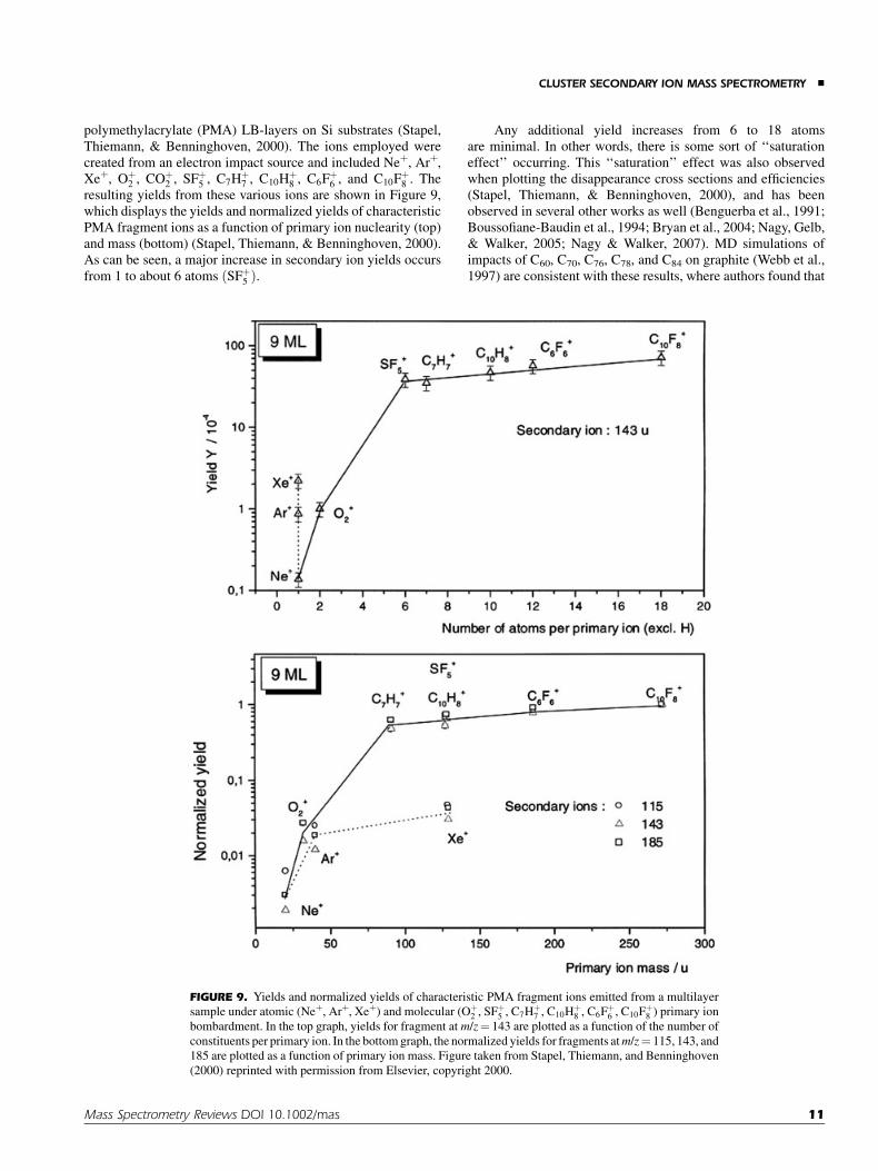
polymethylacrylate (PMA) LB-layers on Si substrates (Stapel,Thiemann, & Benninghoven, 2000). The ions employed werecreated from an electron impact source and included Neþ, Arþ,Xeþ, Oþ
2 , COþ2 , SFþ
5 , C7Hþ7 , C10Hþ
8 , C6Fþ6 , and C10Fþ
8 . Theresulting yields from these various ions are shown in Figure 9,which displays the yields and normalized yields of characteristicPMA fragment ions as a function of primary ion nuclearity (top)and mass (bottom) (Stapel, Thiemann, & Benninghoven, 2000).As can be seen, a major increase in secondary ion yields occursfrom 1 to about 6 atoms ðSFþ
5 Þ.
Any additional yield increases from 6 to 18 atomsare minimal. In other words, there is some sort of ‘‘saturationeffect’’ occurring. This ‘‘saturation’’ effect was also observedwhen plotting the disappearance cross sections and efficiencies(Stapel, Thiemann, & Benninghoven, 2000), and has beenobserved in several other works as well (Benguerba et al., 1991;Boussofiane-Baudin et al., 1994; Bryan et al., 2004; Nagy, Gelb,& Walker, 2005; Nagy & Walker, 2007). MD simulations ofimpacts of C60, C70, C76, C78, and C84 on graphite (Webb et al.,1997) are consistent with these results, where authors found that
FIGURE 9. Yields and normalized yields of characteristic PMA fragment ions emitted from a multilayer
sample under atomic (Neþ, Arþ, Xeþ) and molecular (Oþ2 , SFþ
5 , C7Hþ7 , C10Hþ
8 , C6Fþ6 , C10Fþ
8 ) primary ion
bombardment. In the top graph, yields for fragment at m/z¼ 143 are plotted as a function of the number of
constituents per primary ion. In the bottom graph, the normalized yields for fragments atm/z¼ 115, 143, and
185 are plotted as a function of primary ion mass. Figure taken from Stapel, Thiemann, and Benninghoven
(2000) reprinted with permission from Elsevier, copyright 2000.
CLUSTER SECONDARY ION MASS SPECTROMETRY &
Mass Spectrometry Reviews DOI 10.1002/mas 11

the penetration depth and number of displaced atoms was foundto be independent of the molecule size in this range.
Stapel and co-workers also noted that there was no observedchemical effect when using fluoronated beams such as SFþ
5 understatic SIMS conditions as there was no observed difference whenchanging from fluorine containing primary ions to hydrocarbonprimary ions of comparable mass. All efficiencies were muchgreater for the molecular beams as compared to the atomicbeams, however at extremely low energies (<1 keV), theperformance of Xeþ outweighed the performance of SFþ
5
(secondary ion formation efficiencies were higher for Xeþ thanfor low energy SFþ
5 ). This was attributed to the fact that 1 keVSFþ
5 bombardment corresponds to only 150 eV per atom, anenergy close to the sputter threshold (see Appendix fordefinitions) (Stapel, Thiemann, & Benninghoven, 2000).
Again, it should be noted, that Cþ60 and other large cluster
ions, such as Auþ400 and massive gas clusters, are not included in
Stapel’s studies (Stapel, Thiemann, & Benninghoven, 2000).Some of these massive projectiles are known to exhibit abundantmulti-ion emission (the emission of multiple ions from a singleprojectile impact) resulting in even further enhancements inion yield (Verkjoturov et al., 2006). It is believed that theseenhancements result from the different behavior of the massiveprojectiles when bombarding a surface as compared to smallercluster projectiles. More specifically, the atoms in these massiveprojectiles tend to behave as a collective unit when bombarding asurface, as opposed to smaller clusters, where each atom in thecluster forms its own individual collision cascades (Czerwinskiet al., 2006).
G. Matrix-Enhanced and Metal-Assisted Cluster SIMS
One way of improving molecular signals prior to the advent ofcluster SIMS was to use matrix-enhanced or metal-assistedSIMS. In metal-assisted SIMS, the sample is coated with a thinlayer of a metal, such as Au or Ag, which can result in significantenhancements in signal (by a factor of 10 or more) and theformation of additional adduct ions (Grade & Cooks, 1978;Linton et al., 1993). In matrix-enhanced SIMS, the sample isplaced in a signal enhancing matrix (such as sinapic acid) andanalyzed in a similar manner as Matrix-Assisted LaserDesorption Ionization (MALDI) (Wu & Odom, 1996; Wittmaacket al., 2000).
One of the questions that some scientists have been trying toanswer is whether or not these enhancements will occur withcluster beams as well. Adriaensen et al. attempted to answer thisquestion by depositing Ag and Au layers onto a series of organicdyes and pharmaceuticals and determining the effects onthe secondary ion yields when employing Gaþ and SFþ
5 beams(Adriaensen, Vangaever, & Gijbels, 2004). They found that bothion beams yielded increases in positive secondary ion yields,after deposition of the metal overlayers, though there was amuch-reduced effect observed with SFþ
5 as compared to Gaþ.Later, Delcorte and co-workers characterized the surface
of several polymeric-based samples including PS, PE, and PPcoated with varying amounts of gold (Delcorte, Poleunis, &Bertrand, 2006b; Delcorte and Garrison, 2007; Delcorte et al.,2007). The samples were analyzed with Gaþ, Inþ, and Cþ
60
probes. In general it was found that gold metallization of thesurface did not provide a significant enhancement of thecharacteristic fragment and parent-like ion yields when employ-ing Cþ
60. However, it was found that Cþ60 lead to an enormous yield
enhancement for characteristic gold clusters (three orders ofmagnitude over what was observed for Gaþ). The general trendobserved was that while increasing coverage of the surface bygold leads to increasing organic ion yields when using Gaþ
projectiles, the ion yields decrease with increasing coverage withCþ
60 bombardment.Another example of metal-assisted cluster SIMS was
published recently by Guillermier et al. (2006b). In this work,the authors used a Au4þ
400 probe at 136 keV impact energy tocharacterize a sample of glycine coated with 1 nm of Ag, wherethe yields of the CN� ion were doubled with the silver coating. Amultitude of CN-based Ag clusters were also formed. However,similar to Delcortes’ work, the molecular ion signal was notenhanced by the metal overlayer. In fact, the molecular ion signaldropped dramatically when coated with Ag.
A good example of matrix-enhanced cluster SIMS oforganic samples was given by Locklear et al., who used aspecialized Cþ
60 source, in the event-by-event mode (seesource section) to investigate the emission of the gramicidin S(M–H)� ion embedded in a matrix of sinapic acid. There was anobserved increase in ion yield by up to 8 times, simply bycontrolling the ratio of gramicidin S to sinapic acid (Locklearet al., 2006).
Finally, both metal-assisted SIMS and matrix-enhancedSIMS were studied employing Biþ polyatomic sources byMcDonnell et al. (2006) for biological systems. In this work,the authors characterized Au-coated and matrix-coated (with2,5-dihydroxybenzoic acid sprayed onto the surface) tissuesamples with varying cluster sizes. The authors found a similarenhancement when either employing Biþ1 with a gold coating orusing Biþ3 with no coating (as compared to Biþ1 with no Aucoating). Characterizing the Au-coated sample with Biþ3 primaryions resulted in even further increases in signal. Similar resultswere obtained from matrix-enhanced SIMS. This effect however,was observed only in the positive ion mode, most likely becausethe mechanisms involve the attachment of protons (which willonly be observed in the positive ion mode).
H. 2-D Imaging
The signal enhancements employed for mass spectral analysiscan be extremely beneficial for imaging applications, particularlywhen looking for trace constituents in the mid- to high-massregion, as there can be a dramatic increase in signal in this region.Unfortunately, there is typically an increase in the backgroundsignal when employing cluster beams. This can be particularlyproblematic in the low-mass range, as it may lead tointerferences.
The increased signal associated with these cluster sources,particularly liquid metal ion sources such as Au and Bi clustersources, has led to a large amount of research on biological tissueimaging applications, where these sources have been shownto yield very intense secondary ion images, particularly ofphospholipids and cholesterol, in brain tissue (Sjovall, Lausmaa,
& MAHONEY
12 Mass Spectrometry Reviews DOI 10.1002/mas

& Johansson, 2004; Touboul et al., 2004, 2005b; Nygren et al.,2005), cardiac tissue (Aranyosiova et al., 2006), and otherbiological cross sections (Touboul et al., 2005a). For an overviewof biological tissue imaging with LMIG cluster sources, seereferences (Brunelle, Touboul, & Laprevote, 2005).
C60 sources have also been used for bioimaging andbioanalysis applications (Brunelle et al., 1997; Baker et al.,2006). Although the spot size is much greater for the Cþ
60 source,than for LMIG sources, the signal enhancement tends to be muchgreater for Cþ
60, and it tends to be more surface-sensitive due to thereduced penetration depth of the beam as compared to LMIGclusters (Baker et al., 2006). Jones et al. for example comparedAuþ3 to Cþ
60 for biological imaging applications, where theauthors attempted to image the distribution of a drug, raclopride,in a rat brain section. As expected, the highest efficiencies (E)were found for Cþ
60 (Jones, Lockyer, & Vickerman, 2007).Although the drug was detected with Cþ
60, the distribution bySIMS did not corroborate with the known locations of thereceptor sites. This was attributed to commonly occurring matrixeffects in SIMS. More specifically, the protonated molecular ionof the drug, (MþH)þ, was enhanced in regions which containedlarge amounts of cholesterol, while it was suppressed in regionscontaining high amounts of phosphatidylcholine. This wasattributed to the cholesterol acting as a source of protons forthe drug (Jones, Lockyer, & Vickerman, 2006) in that it tends toform deprotonated molecular ions (M–H)þ, while the phospha-tidlycholine removes a proton from the environment by formingprotonated molecular ions (MþH)þ and therefore suppressesthe formation of the protonated molecular ion in the drug. Thiswas a very important result, helping to better understandionization phenomena in complex matrices.
An example of Cþ60 imaging in polymeric based materials is
given by Xu and co-workers (Xu et al., 2004), who compared Gaþ
and Cþ60 primary ion probes for imaging in combinatorial resin
particles (Fig. 10). Though the image resolution in the figure isvery poor as compared to liquid metal ion sources, the benefits ofusing Cþ
60 as a probe are evident in that there are much higherintensities and efficiencies as compared to that observed with theGaþ probe (by �2 orders of magnitude). Also, when Cþ
60 is used,the signals originating from the polymer are more intense thanthose measured from the silicon substrate, whereas the oppositeis observed in the image obtained with Gaþ. Charge compensa-tion was found to improve dramatically as well when using Cþ
60,where it was not necessary to use an electron flood gun duringanalysis.
V. AN INTRODUCTION TO POLYMERDEPTH PROFILING
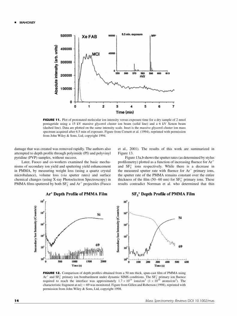
The first demonstration of ‘‘molecular depth profiling’’ withcluster ion beams was published in 1994, where authorsemployed massive glycerol cluster ions to characterize variousbiological samples (Cornett, Lee, & Mahoney, 1994). Theprimary results of this work are depicted in Figure 11, whichshows secondary ion intensities from a protein sample (pentage-tide), plotted as a function of increasing sputter time for bothglycerol cluster ions and Xeþ atomic ions. The investigators were
able to demonstrate that when employing glycerol cluster ions,instead of atomic ions, the signal remained constant withincreasing sputtering time. In contrast, when similar experimentswere performed with Xeþ ions, there was rapid signal decay withsputtering time. They attributed this behavior to much slowersample damage accumulation when using the low-energy clustersources as opposed to the intense energetic atomic beams, whichcause rapid sample destruction.
The first ‘‘molecular depth profile’’3 of a polymeric samplewas demonstrated not much later by Gillen and Roberson (1998)using an SFþ
5 cluster source. The results from this work aredepicted in Figure 12, which compares depth profiles of a PMMAsample cast onto a silicon substrate. Here, the signal intensity ofm/z¼ 69, a fragment characteristic of PMMA, was plotted as afunction of increasing sputter time with both Arþ (left panel) andSFþ
5 (right panel). While there was rapid signal degradation whenusing Arþ, the signal remained relatively constant with increas-ing sputter time when employing SFþ
5 clusters. The substrate wasreached after only 200 sec of sputtering with the SFþ
5 source,while the polymer/Si interface could only be reached afterprolonged sputtering of the film at higher primary ion currentswhen employing the Arþ source.
The success of the polymeric depth profile was attributed toboth surface-localized damage and increased sputter rates. Inother words, there was very little subsurface damage, and the
FIGURE 10. SIMS images (400 mm� 400 mm) of Biotin-Sasrin
linker—copoly(styrene-1% divinylbenzene) resins acquired with (a)
Gaþ, and (b) Cþ60 primary ions. The images on the left in both panels are
the total ion images, while the images on the right show an image overlay
of the biotin molecular ion (blue), and silicon (red) from the substrate.
Figure taken from Xu et al. (2004), reprinted with permission from
American Chemical Society, copyright 2006.
————3Note that any depth profile obtained from polymers using this
technique is not a true ‘‘molecular’’ depth profile, because one is
typically measuring fragment ion intensities that are characteristic of
the polymer as a function of depth and not the polymer molecule itself.
CLUSTER SECONDARY ION MASS SPECTROMETRY &
Mass Spectrometry Reviews DOI 10.1002/mas 13
damage that was created was removed rapidly. The authors alsoattempted to depth profile through polyimide (PI) and polyvinylpyridine (PVP) samples, without success.
Later, Fuoco and co-workers examined the basic mecha-nisms of secondary ion yield and sputtering yield enhancementin PMMA, by measuring weight loss (using a quartz crystalmicrobalance), volume loss (via sputter rates) and surfacechemical changes (using X-ray Photoelectron Spectroscopy) inPMMA films sputtered by both SFþ
5 and Arþ projectiles (Fuoco
et al., 2001). The results of this work are summarized inFigure 13.
Figure 13a,b shows the sputter rates (as determined by stylusprofilometry) plotted as a function of increasing fluence for Arþ
and SFþ5 ions respectively. While there is a decrease in
the measured sputter rate with fluence for Arþ primary ions,the sputter rate of the PMMA remains constant over the entirethickness of the film (50–60 nm) for SFþ
5 primary ions. Theseresults contradict Norrman et al. who determined that thin
FIGURE 11. Plot of protonated molecular ion intensity versus exposure time for a dry sample of 2 nmol
pentagetide using a 15 kV massive glycerol cluster ion beam (solid line) and a 6 kV Xenon beam
(dashed line). Data are plotted on the same intensity scale. Inset is the massive glycerol cluster ion mass
spectrum acquired after 6.5 min of exposure. Figure from Cornett et al. (1994), reprinted with permission
from John Wiley & Sons, Ltd, copyright 1994.
FIGURE 12. Comparison of depth profiles obtained from a 50 nm thick, spun-cast film of PMMA using
Arþ and SFþ5 primary ion bombardment under dynamic SIMS conditions. The SFþ
5 primary ion fluence
required to reach the interface was approximately 1.7� 1015 ions/cm2 (1� 1016 atoms/cm2). The
characteristic fragment at m/z¼ 69 was monitored. Figure from Gillen and Roberson (1998), reprinted with
permission from John Wiley & Sons, Ltd, copyright 1998.
& MAHONEY
14 Mass Spectrometry Reviews DOI 10.1002/mas

overlayers of PMMA depth profiled with SFþ5 yields non-linear
increases in sputter rate (Norrman, Haugshoj, & Larsen, 2002).However, this increased sputter rate in this particular study ishighly correlated with decreased coverage of the PMMA on theSi substrate at low concentrations. Thus, significant changes inthe sputter mechanisms are likely. The finding of constant sputterrate with film thickness has been repeated with other polymericmaterials, with similar results (Shard et al., 2007).
XPS studies indicated that there were significantly higher Cconcentrations and lower O concentrations when sputtering withArþ as compared to SFþ
5 ions under similar conditions (Gillen &Roberson, 1998), consistent with increased chemical damage inthe form of side-chain cleavage when employing the atomicsource. The high-resolution XPS spectra also illustrate signifi-cant differences in the resulting chemistries. Figure 13c depictsthe high-resolution C(1s) XPS spectra of the native PMMAsurface as compared to SFþ
5 and Arþ-bombarded regions. In thenative PMMA, there are three major components, the largestbeing the aliphatic carbon peak at a binding energy of 285.0 eV.
There is also a methoxylic carbon component, which is shiftedto slightly higher binding energies (286.5 eV). Finally, thecarboxylic carbon peak occurs at 288.9 eV. As can be seen, theresults indicated a significant loss of the carboxylic carbonmoiety upon sputtering with Arþ as compared to SFþ
5 . This isfurther evidence for decreased chemical damage when employ-ing cluster beams. The overall results for Arþ were consistentwith what had been observed previously with atomic bombard-ment of PMMA (Licciardello et al., 1996; Pignataro, Fragala, &Puglisi, 1997).
XPS of other cluster ion-bombarded polymeric materialshave yielded similar results when comparing atomic andpolyatomic bombardment, indicating decreased chemical dam-age when employing polyatomic sources in materials such asPTFE (Sanada et al., 2004), PLA (Yotoriyama et al., 2006;Mahoney et al., 2007b), and polycarbonate (PC) (Zemek et al.,1999).
It should be noted that at energies lower than 1 keV(0.7 keV), the sputter properties (i.e., sputter yields and depth
FIGURE 13. (a) Sputter rate measurements plotted as a function of increasing ion fluence for PMMA
bombarded with 5.5 keV Arþ ions, (b) Sputter rate measurements plotted as a function of increasing ion
fluence for PMMA bombarded with 5.5 keV SFþ5 ions, and (c) Comparison of the C(1s) core level XPS
spectra acquired from a PMMA sample bombarded with SFþ5 and Arþ ions. Figure from Fuoco et al. (2001),
reprinted with permission from American Chemical Society, copyright 2001.
CLUSTER SECONDARY ION MASS SPECTROMETRY &
Mass Spectrometry Reviews DOI 10.1002/mas 15

profile compositions) of SFþ5 were found to be similar to Arþ
(Fuoco et al., 2001). More specifically, the sputtering yields ofboth ions at 0.7 keV were very low, and the depth profilesindicated increased damage accumulation as compared to whatwas observed for 3 keV SFþ
5 . The poor performance of the lowenergy SFþ
5 ions was attributed to the fact that 0.7 keV SFþ5
bombardment corresponds to an energy close to or below thesputter threshold for the PMMA, previously defined as 150 eVper atom (Stapel, Thiemann, & Benninghoven, 2000). Thoughsputtering is often observed subthreshold for many clusters due tothe non-linear nature of the sputtering event, SFþ
5 is a relativelysmall cluster, so the sputtering threshold may play a bigger role inthis case.
Brox et al. compared depth profiles of several differentpolymers using Arþ, SFþ
5 , Csþ, and Xeþ (Brox, Hellweg, &Benninghoven, 2000) to explore the capabilities and limitationsof cluster beams for polymer depth profiling. While Arþ
bombardment resulted in rapid signal decay in all cases, Csþ,Xeþ, and SFþ
5 were able to profile through certain materialswithout complete loss of characteristic signal. The best resultshowever, were obtained with SFþ
5 , yielding constant signals as afunction of depth. The sputtering yields measured in this study,were found to increase in the order of Arþ<Xeþ< SFþ
5 .The successful depth profiles in this study included thin
films of poly(propyleneglycol) (PPG), PEG, and PMMA. In theseprofiles there was a characteristic decrease in signal intensity atthe beginning of the sputtering process, followed by a more orless pronounced stabilization of the signals until the Si interfacewas reached. At this point, the substrate ion intensities increasedrapidly with a commensurate decrease in polymer fragment ionsignals. While these polymers did maintain characteristic
molecular signals as a function of increasing fluence, there werestill many more polymers that did not, including PC, PS, PE, andpolyisoprene (PIP). In addition, all bulk polymers except forPTFE showed an immediate and rapid decrease in characteristicsecondary ion emission for all applied sputter ions. The authorsconcluded that polymeric depth profiling was more of anexception than a rule (Brox, Hellweg, & Benninghoven, 2000).
However, starting with the discovery of well-behavedpolyesters by Mahoney, Roberson, and Gillen (2004), andfollowed by the determination and optimization of importantexperimental parameters, such as temperature (Mahoney et al.,2006a, 2007b; Mahoney, Patwardhan, & McDermott, 2006b;Mollers et al., 2006; Mahoney, Fahey, & Gillen, 2007a), beamchemistry and size (e.g., Cþ
60 or SFþ5 or Ar2000), beam angle
(Kozole, Wucher, & Winograd, 2008) and beam energy (Fisheret al., 2008; Shard et al., 2008), it is now understood that this is notthe case, and that even polymers that were originally thought of as‘‘impossible to depth profile’’ (e.g., PS), can now be depthprofiled using certain cluster beams.
In general, attempts to depth profile through polymeric (andother organic) materials will result in one of the followingscenarios depicted in Figure 14. In polymers that are moreamenable to being depth profiled (such as PLA, PGA, and PCL),the materials will undergo an initial (exponential) signal intensitydrop (region 1) (in some cases, there may be an initial increase inintensity). This region has been researched thoroughly andits shape predicted somewhat by the erosion model describedearlier for molecular samples (Gillen, Simons, & Williams, 1990;Cheng, Wucher, & Winograd, 2006; Wucher, 2008). Next is aconstant signal intensity or steady-state signal region (region 2),and finally, an interfacial region where the signal intensity drops
FIGURE 14. Different scenarios (a–d) in polymeric depth profiling: In thin films, there are typically 3
regions: (1) Initial drop in signal intensity often defined by disappearance cross section of the material.
(2) A steady state region (or pseudo-steady state region in the case of b) and interfacial region. In bulk
materials there is almost always an eventual loss of signal intensity after a certain critical fluence. This
critical fluence varies with source and energy. [Color figure can be viewed in the online issue, which is
available at www.interscience.wiley.com.]
& MAHONEY
16 Mass Spectrometry Reviews DOI 10.1002/mas
with a corresponding increase in substrate signal (region 3).In polymers that are not amenable to depth profiling underpolyatomic bombardment, the signal degrades immediately, suchas in the case of PS, PE, PP, and PC (Fig. 14c) under Cþ
60 or SFþ5
bombardment. The substrate will eventually be reached, but theinterface width will typically be broad. Some cases exibitintermediate behavior, such as PMMA under SFþ
5 bombardment(Fig. 14b). Eventually even the materials that are amenable tobeing depth profiled will lose signal, under higher fluences,typically in a manner as that depicted in Figure 14d. Whatdetermines which materials will behave as that shown inFigure 14a or b as opposed to that observed in Figure 13c? Whatcauses the eventual loss of signal shown in Figure 14d? A goodportion of the answer has already been determined through well-known degradation chemistries in polymers, which will bedescribed in greater detail in the next section.
VI. RADIATION CHEMISTRY INPOLYMERIC MATERIALS
A. Background
There are generally two groups of polymers, often referred to asType I and Type II polymers (Chapiro, 1962). Type I polymerstypically crosslink when irradiated by various types of radiation(such as electrons, neutrons, alpha particles, accelerated ions,X-rays, gamma rays, and beta rays). These include polymerssuch as polyethylene, polystyrene, and other polymeric materialsthat are either aromatic or have very little branching associatedwith them. Type II polymers however, pre-dominantly degradeunder irradiation through a random chain scission process.Type II polymers, include polymers such as PIB, PMMA,and poly(a-methylstyrene) (PAMS) and other polymers withincreased branching or ‘‘weakened’’ points located on the main-chain backbone (Chapiro, 1962; Calcagno, 1995).
In both types, the mechanisms of degradation are complexand are known to involve free radical intermediates. Tables 1–3list several polymers and their characteristics under irradiation(Type I and Type II polymers). Also listed in the tables are thegases given off during the irradiation, and the polymers behaviorunder cluster ion bombardment (i.e., do they depth profile tosome degree when employing cluster beams, and if so, whichbeams are required?). In general, it can be seen that polymerswith high concentrations of quaternary carbon atoms alongthe chain (e.g. CH2–CR2) undergo scission, while those with astructure of CH2–CH2 or CH2–CHR tend to crosslink. It isassumed that the presence of a tetrasubstituted carbon in the chaincauses strain in the molecule by a steric repulsion effect. Thisresults in the main chain being weakened.
It also appears that the most radiation-resistant (cross-linking) polymers contain aromatic substituents. There is a highradiation resistance of the aromatic nucleus. This effect is saidto be related to the deactivation or ‘‘protection’’ produced byaromatic compounds. The charge formed is resonance-stabilizedand so the molecule does not lose its structure. Also, any activatedstate is likely to lose its energy through internal conversion(Chapiro, 1962).
Several polymers of group I, which normally cross-linkunder irradiation, can be degraded if irradiated in a highly dividedform (i.e., with a large surface to volume ratio) in the presence ofoxygen. It is most likely that when irradiation is carried out in air,some of the polymeric radicals, which would otherwise lead tocrosslinking, react with O2 to form peroxidic structures whicheventually decompose and cause oxidative degradation of themain chain. This effect is particularly pronounced in polymerswhich can be easily oxidized such as for polypropylene. Anothergood example is PTFE, which undergoes extreme degradation inthe presence of O2. However, when Teflon is irradiated in theabsence of oxygen, this polymer also suffers much less radiationdamage.
When bulk polymers are subjected to irradiation, theseeffects are less pronounced, since the oxidation process is thendiffusion-controlled and becomes noticeable only at very lowfluence rates, when the rate of diffusion of O2 into the polymer ishigher than the rate of consumption of this gas by the chemicalreactions. On the other hand, O2 can inhibit the degradationprocess in polymers such as PMMA when irradiated in a highlydivided form. It is likely that either the deactivation of polymericfree radicals or an energy transfer involving excited polymericmolecules by O2 is occurring in this case.
Another way to convert a crosslinking polymer into adegrading polymer, is to use specific conditions favoring theformation of a radical polymer-halogen. For PS, for example thereaction is carried out in halogenated solvents (CCl4, CHCl3) inthe presence of O2.
Even in Type II samples, crosslinking eventually pre-dominates under higher fluences. A good example of this isPMMA, which has been studied extensively. PMMA behavesas a positive resist at low fluences, but behaves as a negativeresist at high fluences (Licciardello et al., 1996). Upon ionbombardment, the molecular weight initially decreases withfluence, but at higher fluences the molecular weight actuallystarts increasing.
The structure of the subsurface region of PMMA bombardedwith low energy (250 eV) Arþ ions was studied by Koval (2004)who used electron beam lithography and scanning electronmicroscopy to visualize these layers. In this work, the ionirradiated PMMA was found to contain three distinct layers. Thetop layer was comprised of an insoluble graphitized materialdisplaying a substantial electrical conductance. Underneath thegraphitized PMMA layer, a highly crosslinked stratum wasobserved, which was found to be insoluble in acetone, like thegraphitized region, yet was not conducting. Finally, a lowmolecular weight layer was located between the crosslinkedlayer and the bulk PMMA. This layer was observed by selectivelydissolving it away using solutions of methyl isobutyl ketone/isopropyl alcohol (MIBK/IPA).
In addition to crosslinking, polymers will tend to formdouble bonds upon irradiation, increasing the extent ofunsaturation in the material. This will often cause a discolorationat higher fluences (Chapiro, 1962). Cyclization also can occurunder irradiation via intermolecular, and intramolecular cross-linking. It has been suggested that this process is particularlyfavored by crystallinity (Chapiro, 1962). SIMS results areconsistent with this (Mahoney, Patwardhan, & McDermott,2006b).
CLUSTER SECONDARY ION MASS SPECTROMETRY &
Mass Spectrometry Reviews DOI 10.1002/mas 17

TABLE 1. Polymeric structures and their behavior under irradiation
Polymer Structure Type I -Crosslinking
Type II -Degrading Depth profiles?**
Gases givenoff (in
atmosphere)
PE CH2 CH2 n x Yes - low energy Cs+/O2+ or
massive gas cluster only†† H2, C3H8
PP CH CH2 n
CH3x Yes - low energy Cs+/O2
+ ormassive gas cluster only†† H2, CH4
PIB CH2 Cn
CH3
CH3
x Yes(Braun, 2006; Gillen, 2006c)
H2, CH4,CO2, C3H8
Poly(vinylalcohol) CH2 CH nOH
x ----- H2 and CO
PAN* CH2 CH nCN
x ----- H2, NH3,C2N2
PVPCH2 CH n
NO x Yes
(Cramer, 2008)
PSCH2 CH n x Yes - low energy Cs+/O2
+ ormassive gas cluster only†† H2
PAMS CH2 C n
CH3
x Yes(Mollers, 2006)
PVC CH2 CH nCl
x Yes†
(Norrman, 2002) HCl
PVDC C CH2 n
Cl
Cl
x -----
PVDF C CH2 n
F
F
x Yes(Hinder, 2007)
PTFE C C
F
F
F
F n
x Yes(Brox, 2001)
CO, CO2,CF4
PTCE C C
Cl
Cl
Cl
Cl n
x -----
PTCFE C C
Cl
Cl
F
F n
x -----
PBD* CH CH CH2CH2 n x ----- H2, CH4
PIPCH C CH2CH2
CH3
n x No(Brox, 2001)
H2, CH4,CO2, C3H8
Polymers are grouped according to their structural features.
*PAN, polyacrylonitrile; PBD, polybutadiene.
**The answers reported reflect the current state of the literature, under the conditions the literature specifies.{Rise of Si substrate signal reported only.{{Mine et al. (2007), Cramer et al. (2008), Houssiau, Douhard, and Mine, (2008), Ninomiya et al. (in press).
& MAHONEY
18 Mass Spectrometry Reviews DOI 10.1002/mas

TABLE 2. Polymeric structures and their behavior under irradiation
Polymer Structure Type I -Crosslinking
Type II -Degrading
Depthprofiles?**
Gases givenoff (in
atmosphere)
PEO CH2 CH2 On x Yes
(Brox, 2001)
PPO CH2 CH On
CH3x Yes
(Brox, 2001)
PLA CH C On
CH3
O
x Yes(Mahoney, 2004)
PGA CH2 C On
Ox Yes
(Mahoney, 2004)
PCL (CH2)5 C On
Ox Yes
(Mahoney, 2004)
PETCC
O
O
O
OCH2CH2 nx Yes
(Conlan, 2006)
PC O C
CH3
CH3
O C
O
n
x
Yes - low energyCs+/O2
+ ormassive gas
cluster only††
polyacrylamideCH2 CH n
C ONH2
x -----
polymethacrylamideCH2 C n
C O
NH2
CH3
x -----
Polycaprolactam (CH2)5 C NHn
O----- H2, CO, CO2,
N2, O2
PU NH CR1
O
R2NH C
O
nx Yes
(Mahoney, 2006b)
Polyamides x
Polyimides (PI) x Yes - massivegas cluster only††
PDMS Si O
CH3
CH3 n
x Yes(Gillen, 1998)
H2, CH4,C2H6
Cellulose andderivatives x Yes
(Fletcher, 2006b)
DNA ----- x
proteins Yes(Gillen, 1998)
Polymers are grouped according to their structural features.
**The answers reported reflect the current state of the literature, under the conditions the literature specifies.{{Mine et al. (2007), Cramer et al. (2008), Houssiau, Douhard, and Mine (2008), Ninomiya et al. (in press).
CLUSTER SECONDARY ION MASS SPECTROMETRY &
Mass Spectrometry Reviews DOI 10.1002/mas 19
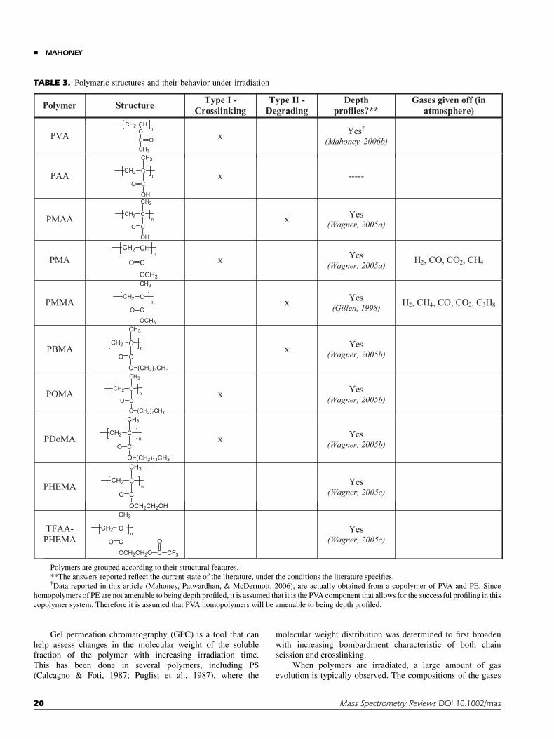
Gel permeation chromatography (GPC) is a tool that canhelp assess changes in the molecular weight of the solublefraction of the polymer with increasing irradiation time.This has been done in several polymers, including PS(Calcagno & Foti, 1987; Puglisi et al., 1987), where the
molecular weight distribution was determined to first broadenwith increasing bombardment characteristic of both chainscission and crosslinking.
When polymers are irradiated, a large amount of gasevolution is typically observed. The compositions of the gases
TABLE 3. Polymeric structures and their behavior under irradiation
Polymer Structure Type I -Crosslinking
Type II -Degrading
Depthprofiles?**
Gases given off (inatmosphere)
PVACH2 CH nO
C OCH3
x Yes†
(Mahoney, 2006b)
PAACH2 C
n
CH3
CO
OH
x -----
PMAACH2 C
n
CH3
CO
OH
x Yes(Wagner, 2005a)
PMACH2 CH
nCO
OCH3
x Yes(Wagner, 2005a) H2, CO, CO2, CH4
PMMACH2 C
n
CH3
CO
OCH3
x Yes(Gillen, 1998) H2, CH4, CO, CO2, C3H8
PBMACH2 C
n
CH3
CO
O (CH2)3CH3
x Yes(Wagner, 2005b)
POMACH2 C
n
CH3
CO
O (CH2)7CH3
x Yes(Wagner, 2005b)
PDoMACH2 C
n
CH3
CO
O (CH2)11CH3
x Yes(Wagner, 2005b)
PHEMACH2 C
n
CH3
CO
OCH2CH2OH
Yes(Wagner, 2005c)
TFAA-PHEMA
CH2 Cn
CH3
CO
OCH2CH2O C
O
CF3
Yes(Wagner, 2005c)
Polymers are grouped according to their structural features.
**The answers reported reflect the current state of the literature, under the conditions the literature specifies.{Data reported in this article (Mahoney, Patwardhan, & McDermott, 2006), are actually obtained from a copolymer of PVA and PE. Since
homopolymers of PE are not amenable to being depth profiled, it is assumed that it is the PVA component that allows for the successful profiling in this
copolymer system. Therefore it is assumed that PVA homopolymers will be amenable to being depth profiled.
& MAHONEY
20 Mass Spectrometry Reviews DOI 10.1002/mas

vary from polymer to polymer and some examples are listed inTables 1–3. In most cases of gas measurements, the yields areinitially higher and decrease with increasing irradiation (Chapiro,1962). The yield of gas is also much higher when the irradiation iscarried out at higher temperatures and particularly if the polymeris irradiated above its glass transition temperature. If a polymer isheated high enough, a chain depolymerization process may beinitiated by the free radicals which are trapped in the polymer(Chapiro, 1962).
To summarize, polymeric materials typically demonstratethree distinct chemistries as a function of increasing irradiationfluence: (1) First, degradation mechanisms dominate (partic-ularly in Type II polymers), (2) After a certain fluence, which isdependent upon the polymer and the radiation conditions,crosslinking dominates, and (3) Finally, under higher fluences,graphitization of the surface occurs, resulting in a significantincrease in the conductance of the irradiated region. In Type Imaterials, the crosslinking happens at a much higher rate andat times the degradation is skipped altogether. The following are alist of factors that typically affect the behavior of the polymerduring irradiation:
1. Molecular weight: Higher molecular weight polymerscrosslink faster than lower molecular weight polymers.
2. Total fluence: Increased fluences result in increasedcrosslinking.
3. Fluence rate: The extent of crosslinking is not influencedby the rate at which the fluence is delivered to the polymersample, unless O2 is present.
4. Crystallinity: the extent of crosslinking is typically lowerin highly crystalline materials due to trapped radicals(since the mobility of polymeric segments is much lowerin these regions). In general for semicrystalline polymers,the crystalline content tends to decrease with increasingfluence, particularly when the sample is brought above itsglass transition temperature. Cyclization tends to increasein these materials.
5. Temperature: The extent of crosslinking decreaseswith decreasing temperature, in particular below the glasstransition temperature. There appears to be decreaseddegradation or main chain scission occurring at lowtemperatures as well.
6. O2: The presence of O2 during irradiation can causenormally crosslinking polymers to degrade via peroxideformation. O2 can also behave as a free radical inhibitorand prevent degradation in certain cases.
B. Atomic Ion Bombardment of Polymers
There has been a lot of research focused specifically on thechemistry of atomic ion-bombarded polymer surfaces, as thisinformation is useful for many applications (photoresists, ion-beam lithography, biomaterials etc.). Specific examples of thisinclude PET (Balik & Said, 1987), PS, PE, and PVDF (Calcagno,1995). These studies have all indicated major physical andchemical property changes in the surface regions of the polymers,which may or may not be permanent, depending on the fluence.In most cases, there are significant changes in the mechanical
(Lee et al., 1991, 1993, 1997; Nishimiya et al., 1991; Lee, Lee, &Mansur, 1992; Ochsner et al., 1993; Rao, Wang, & Lee, 1993;Rao et al., 1995; Tretinnikov & Ikada, 1998), chemical (Puglisiet al., 1986; Nishimiya et al., 1991; Lee et al., 1993, 1997;Svorcık et al., 1998; Tretinnikov & Ikada, 1998), electronic(Forrest et al., 1982; Venkatesan et al., 1983; Liu, Liu, & Zhai,1989; Lee et al., 1993; Svorcık et al., 1997), diffusion (Calcagnoet al., 1993), optical (Calcagno, Compagnini, & Foti, 1992; Ruck,Schulz, & Beusch, 1997), and rheological properties (Calcagno,Compagnini, & Foti, 1992) of ion-bombarded polymericsamples.
These changes are obviously a result of the increasedcrosslinking and unsaturation occurring in these polymers. Aswith all forms of radiation, ion-bombarded surfaces eventuallybecome graphitic in nature (Davenas et al., 1990), or in rarecases diamond-like (Davenas et al., 1990). While most polymersexhibit an increase in conductivity after irradiation with ionbeams (resulting from the formation of the graphitic phase), it isinteresting to note that polymers exhibiting aromatic orheterocyclic structures tended to display even higher levels ofsurface conductivities (Davenas et al., 1989). It is assumed thatgraphitization is enhanced at polymer surfaces which havebenzene ring components (Lee et al., 1997).
There is also a dramatic change in the morphology aftersputtering (Yoshida & Iwaki, 1987; Svorcık et al., 1997); withsome reporting a smoothing effect (Lee et al., 1991), while othersreport increased topography (Svorcık et al., 1998; Netcheva &Bertrand, 1999). These significant changes in the surfaceproperties often result in changes in the compatibilities of thesepolymers with other elements (Zaporojtchenko et al., 2005). Forexample, ion bombardment of polymeric materials has resultedin increased wettability of PDMS and PS surfaces (Suzuki et al.,1990; Suzuki, Kusakabe, & Iwaki, 1993), and changes in thebiocompatibility of PDMS surfaces (Suzuki et al., 1991, 1992;Yotoriyama et al., 2006).
In most polymeric samples, during ion bombardment, thereis a critical fluence above which crosslinking rapidly acceleratesand the corresponding solubility decreases significantly. Thispoint is considered the gel point of the polymer, and is the point atwhich a three-dimensional network is formed in the polymer. Theprocess of forming a gel is a slow process, involving the diffusionof mobile radicals into the bulk, where they will eventuallycrosslink. It is most likely this process of diffusing radicals forwhich damage accumulation in SIMS depth profiling is based(region II). An example of this is shown in Figure 15, whichshows the solubility of PS plotted as a function of increasingfluence of both Heþ and Hþ ions (Calcagno & Foti, 1991;Calcagno, 1995). It is assumed that the corresponding SIMSspectra will have a similar drop in signal intensity at this point asit is well-known that increased crosslinking is correlated todecreased secondary ion yields in SIMS (Chilkoti et al., 1993).Therefore it is likely that the behavior exhibited by polymers, aswas discussed in Figure 14d, is actually a result of the approach ofthe gel point for that particular material.
As can be seen in Figure 15, the gel point is reached earlierfor heavier ions. In addition, the efficiency of the damageprocesses was determined to be lower for high energy ions thanfor low energy ions. In other words, the gel point was reachedmuch later for higher energy ions. These results were explained in
CLUSTER SECONDARY ION MASS SPECTROMETRY &
Mass Spectrometry Reviews DOI 10.1002/mas 21

terms of the difference in the spatial energy distribution, which ismore localized for a low energy ion. The local energy densityis what determines the crosslinking. The chemical yield ofcrosslinks in PS for example increases with the local energydensity.
These decreased damage effects at higher beam energies areconsistent with SIMS results, which indicate prolonged signallongevity in samples irradiated at higher energies (see SectionVIII-C). Though these energies are much higher than what aretypically used for SIMS applications, and therefore differentsputtering mechanisms apply, the end result is the same; theformation of a highly crosslinked insoluble material.
This gel point also tends to be reached earlier for higher MWsamples, and is highly dependent upon the number averagemolecular weight in particular (Puglisi et al., 1988). It is assumedthat there is a critical number of crosslinks per molecule thatneeds to be attained, and that number is reached earlier for thelarger molecules.
Depth profiling through polymer films can also beperformed using atomic beams. However, with the exception oflow energy (200 eV) Csþ beams (Mine et al., 2007), these profilestypically have significantly increased damage associated withthem such that only elemental signals can be monitored as afunction of depth (all molecular information is essentiallydestroyed). In addition, the sputter rate is significantly reducedwhen employing atomic beams, such that only dynamic SIMSinstruments are typically used. There are several examples ofpolymeric depth profiling with atomic beams including PS(Whitlow & Wool, 1989, 1991; Zhao et al., 1991; Shwarz et al.,1992; Liu et al., 1995; Zheng et al., 1995; Strzhemechny et al.,1997; Rysz et al., 1999; Yokoyama et al., 1999; Shin et al., 2001;Hu et al., 2003; Lin et al., 2003; Harton, Stevie, & Ade, 2006a,b,c;
Harton et al., 2006d), PAMA (Valenty et al., 1984), PBMA(Verhoeven et al., 2004), PEVA (Verhoeven et al., 2004), PC(Valenty et al., 1984), PVDF (Chujo, 1991), PEO (Mattsson et al.,2000; Huang et al., 2001), PMMA (Chujo, 1991; Huang et al.,2001; Hu et al., 2003; Harton, Stevie, & Ade, 2006a,b,c; Hartonet al., 2006d), polydimethyl phenylene oxide (PDPO) (Lin et al.,2003), PVP (Zheng et al., 1995; Pinto, Novak, & Nicholas, 1999;Yokoyama et al., 1999; Harton, Stevie, & Ade, 2006a,b; c; Hartonet al., 2006d), PPV and other polymer based LED materials(Sauer et al., 1995; Bulle-Lieuwma & van de Weijer, 2006), solarcell materials (Bulle-Lieuwma et al., 2003), conducting poly-mers (Gray et al., 1992), video tapes (Chujo, 1991), silicones(Stein, Leonard, & Smith, 1991), and other polymeric materials(Shwarz et al., 1992; Duan et al., 2001; Reynolds et al., 2005).
Though most atomic beams produce a considerable amountof damage precluding the ability to obtain molecular depthprofiles, there are some major breakthroughs occurring in thisarea as well. Low energy Csþ and/or Oþ
2 (200 eV) ion beams aregenerating considerable excitement in the SIMS community fordepth profiling in cases where crosslinking is dominant, such aspolystyrene, polyethylene, polypropylene and polycarbonate(Mine et al., 2007; Cramer et al., 2008; Houssiau, Douhard, &Mine, 2008). In such cases, using low energy Csþ and/or Oþ
2
beams will actually outperform conventional cluster sources,such as SFþ
5 and Cþ60, for polymeric depth profiling applications.
Unlike SFþ5 or Cþ
60, these low energy beams yield constantmolecular signals characteristic of PS, PE, PP, and PC as afunction of increasing fluence in the negative ion mode. It islikely that this effect is in part, a chemical etching effect viainteraction of the Csþ and/or Oþ
2 ions with the polymer sample,yielding reactive intermediates, similar to what is observed withirradiation of polymers in the presence of O2. Either way, this isthe one case where atomic beams outperform most cluster beamsfor in-depth polymeric analysis and should be noted.
VII. POLYMER DEPTH PROFILING APPLICATIONS
A. Surface Cleaning
One of the primary concerns in any TOF–SIMS experiment iscontamination of the surface. Cluster SIMS has shown promisefor sputter removal of surface contaminants. Szymczak andWittmaack first showed this in 1994 with SF�
n clusters (Szymczak& Wittmaak, 1994). Since then, several authors have demon-strated the ability to remove polydimethysiloxane (PDMS)overlayers from contaminated samples (Gillen & Roberson,1998; Mahoney, Roberson, & Gillen, 2004; Mahoney, Fahey, &Belu, 2008).
This cleaning of contaminants from the surface has manyimplications for biologically relevant molecules in frozenaqueous matrices, where the surface is often covered in ice andtherefore no useful information can be obtained. With clustersources however, this problem can be alleviated by sputterremoval of the ice. Though this can also be done with atomicbeams, C60 has been shown to remove this overlayer of ice(Wucher et al., 2004) much more rapidly and with very littledamage to the underlying structure.
FIGURE 15. Soluble fraction as a function of ion fluence for 9,000 amu
polystyrene irradiated with 300 keV Hþ and 200 keV Heþ ions. Figure
from Calcagno (1995), reprinted with permission from Elsevier,
copyright 1995.
& MAHONEY
22 Mass Spectrometry Reviews DOI 10.1002/mas

B. Damage Removal
Cluster sources are also able to remove damage previouslycreated by atomic ion beams. This effect was first noticed byMcMahon, Dookeran, and Todd (1995). In this work, secondaryion mass spectra and images were obtained from spikes ofcholine chloride, acetylcholine chloride, and methylphenylpyr-idinium iodide deposited onto specimens of porcine brain tissue.The samples were subjected to a fluence of 10 keV Csþ, sufficientto suppress molecular ion emission. However, following ablationof the samples by massive glycerol clusters, the damage wasremoved. A nice example of this was published more recently byGillen and co-workers (2006a), where the authors were able todemonstrate the recovery of RDX (explosive) molecular signalwhen switching back and forth from C�
1 to C�8 (see Fig. 16).
Similar results have been obtained with Cþ60 probes (Wucher
et al., 2004; Wucher, 2006; Wucher, Chen, & Winograd, 2007).This removal of previously damaged regions has major
implications in possible 3-D Focused Ion Beam SIMS (FIB–SIMS) technology. In FIB milling, a focused Ga beam is used tocross section materials. Characterization of organic FIBcross sections with SIMS however, does not yield any usefulinformation, since Ga beams create large amounts of damage.With cluster beams however, this damaged region can potentiallybe recovered, enabling 3-D analysis of each section.
C. Drug Delivery
The first demonstration of molecular depth profiling in modeldrug delivery systems was published by Mahoney, Roberson,and Gillen (2004). In this work PLA as well as PLA drug-doped(acetaminophen, theophylline) films were depth profiled withSFþ
5 , and it was demonstrated that both polymer and drug
compositions could be monitored as a function of depth on ananoscale using this technique. It was also interesting that therewas evidence of a drug-depleted surface region with composi-tional variation in the bulk. The depth profile quality (depthresolution, signal constancy, rapid sputter rates) was found todeteriorate with increasing drug concentration.
Compositional depth profiling was later performed on aseries of PLA/Pluronic-P1044 polymeric blends of varyingcompositions using SFþ
5 polyatomic primary ion bombardment.The major results from this study are depicted in Figure 17, whichshows actual concentration depth profiles of three differentcompositions (Fig. 17a–c). In each profile, there was a surface-enriched Pluronic-P104 region, followed by a depletion layer,and finally a constant bulk composition region. These diffusionprofiles were consistent with previous models describingpolymer surface segregation. There was also a similar effectoccurring in the buried interfacial region (polymer/Si interface).
Also shown in Figure 17d are the images acquired as afunction of depth for a three component film containing PLA,P104 and insulin, as a model protein drug. Imaging resultsshowed complete coverage of Pluronic at the surface. This wasfollowed by phase separated domains of the Pluronic (40–50mm)in the subsurface region. No signals from insulin were detectedin the positive ion spectrum, most likely because of matrixeffects.
These works resulted in major efforts to further developcluster SIMS technology for characterization of drug deliverysystems and one such application was in the characterization ofdrug-eluting stent (DES) coatings. One of the earliest works toutilize cluster SIMS for such an effort was published in 2006(Mahoney, Patwardhan, & McDermott, 2006b). This workdescribes the efforts to establish feasibility for depth profilingin various materials typically employed for DES applications.These included several polymers currently used or beingdeveloped for this application such as poly(ethylene-co-vinyl-acetate) (PEVA), PU and PLGA, as well as drug-loaded filmscontaining paclitaxel or rapamycin (employed in DES). Theresults indicated that one could depth profile through most ofthese films when employing cluster primary ion beams.
Braun et al. was able to take this a step further anddemonstrate Cþ
60 depth profiling in Taxus Express 2 stents,comprised of a SIBS coating doped with paclitaxel (Braun et al.,2006). The authors were able to etch through approximately1.5 mm of material.
Lastly, PLGA-based stents containing varying amounts ofrapamycin were characterized in three dimensions using an SFþ
5
sputter source in conjunction with a Biþ3 analysis source(Mahoney, Fahey, & Belu, 2008), where the authors were ableto demonstrate 3-D compositional imaging in such systems.The results from this latter study are depicted in Figure 18,where Figure 18a is an overlay of the resulting depth profiles of
FIGURE 16. Variation of RDX characteristic ion signal at m/z¼ 268
under high primary ion fluence sputtering conditions comparing the
effect of C�8 and C�
1 bombardment. Taken from Gillen et al. (2006a) with
permission from John Wiley & Sons, Ltd, copyright 2006.
————4Pluronic surfactants are non-ionic triblock copolymer surfactants
containing alternating PEO and poly(propylene oxide) (PPO) compo-
nents. When used as drug-releasing matrices, these PLA/Pluronic
blends have been proven to extend protein release and minimize the
initial protein burst when compared to the pure PLLA homopolymers.
These systems are of potential use for protein delivery applications.
CLUSTER SECONDARY ION MASS SPECTROMETRY &
Mass Spectrometry Reviews DOI 10.1002/mas 23

samples of varying compositions, and Figure 18b shows the 2-Dimage overlay as a function of sputter depth in a samplecontaining 25% rapamycin in PLGA. From these results, it isvery clear that one can determine overlayer thicknesses andhomogeneities and directly relate this to the release character-istics of the device.
D. Polypeptides
Cheng and Winograd (2005, 2006), Cheng, Wucher, andWinograd (2006), and Cheng et al. (2007) performed a seriesof studies on depth profiling in polypeptide films. The first articlein this series (Cheng & Winograd, 2005) shows the feasibility of
FIGURE 17. Composition depth profiles as measured by SIMS for samples containing: (a) 25% (w/w)
P104 in PLLA, (b) 10% (w/w) P104 in PLLA, and (c) 5% (w/w) P104 in PLLA. (d) Positive secondary ion
images (300 mm� 300 mm) acquired as a function of sputter time for 5% insulin in P104/PLLA blendmatrix
(15% w/w P104). Subparts (a–c) taken from Mahoney, Yu, and Gardella (2005), reprinted with permission
from American Chemical Society, copyright 2005. Subpart (d) taken from Mahoney et al. (2006c), reprinted
with permission from Elsevier, copyright 2006.
& MAHONEY
24 Mass Spectrometry Reviews DOI 10.1002/mas
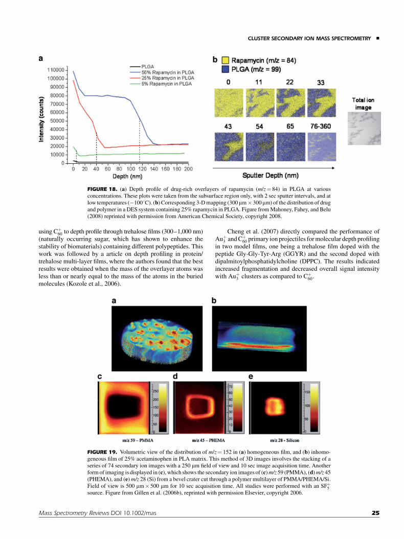
using Cþ60 to depth profile through trehalose films (300–1,000 nm)
(naturally occurring sugar, which has shown to enhance thestability of biomaterials) containing different polypeptides. Thiswork was followed by a article on depth profiling in protein/trehalose multi-layer films, where the authors found that the bestresults were obtained when the mass of the overlayer atoms wasless than or nearly equal to the mass of the atoms in the buriedmolecules (Kozole et al., 2006).
Cheng et al. (2007) directly compared the performance ofAuþ
3 and Cþ60 primary ion projectiles for molecular depth profiling
in two model films, one being a trehalose film doped with thepeptide Gly-Gly-Tyr-Arg (GGYR) and the second doped withdipalmitoylphosphatidylcholine (DPPC). The results indicatedincreased fragmentation and decreased overall signal intensitywith Auþ
3 clusters as compared to Cþ60.
FIGURE 18. (a) Depth profile of drug-rich overlayers of rapamycin (m/z¼ 84) in PLGA at various
concentrations. These plots were taken from the subsurface region only, with 2 sec sputter intervals, and at
low temperatures (�1008C). (b) Corresponding 3-D mapping (300mm� 300mm) of the distribution of drug
and polymer in a DES system containing 25% rapamycin in PLGA. Figure from Mahoney, Fahey, and Belu
(2008) reprinted with permission from American Chemical Society, copyright 2008.
FIGURE 19. Volumetric view of the distribution of m/z¼ 152 in (a) homogeneous film, and (b) inhomo-
geneous film of 25% acetaminophen in PLA matrix. This method of 3D images involves the stacking of a
series of 74 secondary ion images with a 250 mm field of view and 10 sec image acquisition time. Another
form of imaging is displayed in (c), which shows the secondary ion images of (c)m/z 59 (PMMA), (d)m/z 45
(PHEMA), and (e) m/z 28 (Si) from a bevel crater cut through a polymer multilayer of PMMA/PHEMA/Si.
Field of view is 500 mm� 500 mm for 10 sec acquisition time. All studies were performed with an SFþ5
source. Figure from Gillen et al. (2006b), reprinted with permission Elsevier, copyright 2006.
CLUSTER SECONDARY ION MASS SPECTROMETRY &
Mass Spectrometry Reviews DOI 10.1002/mas 25
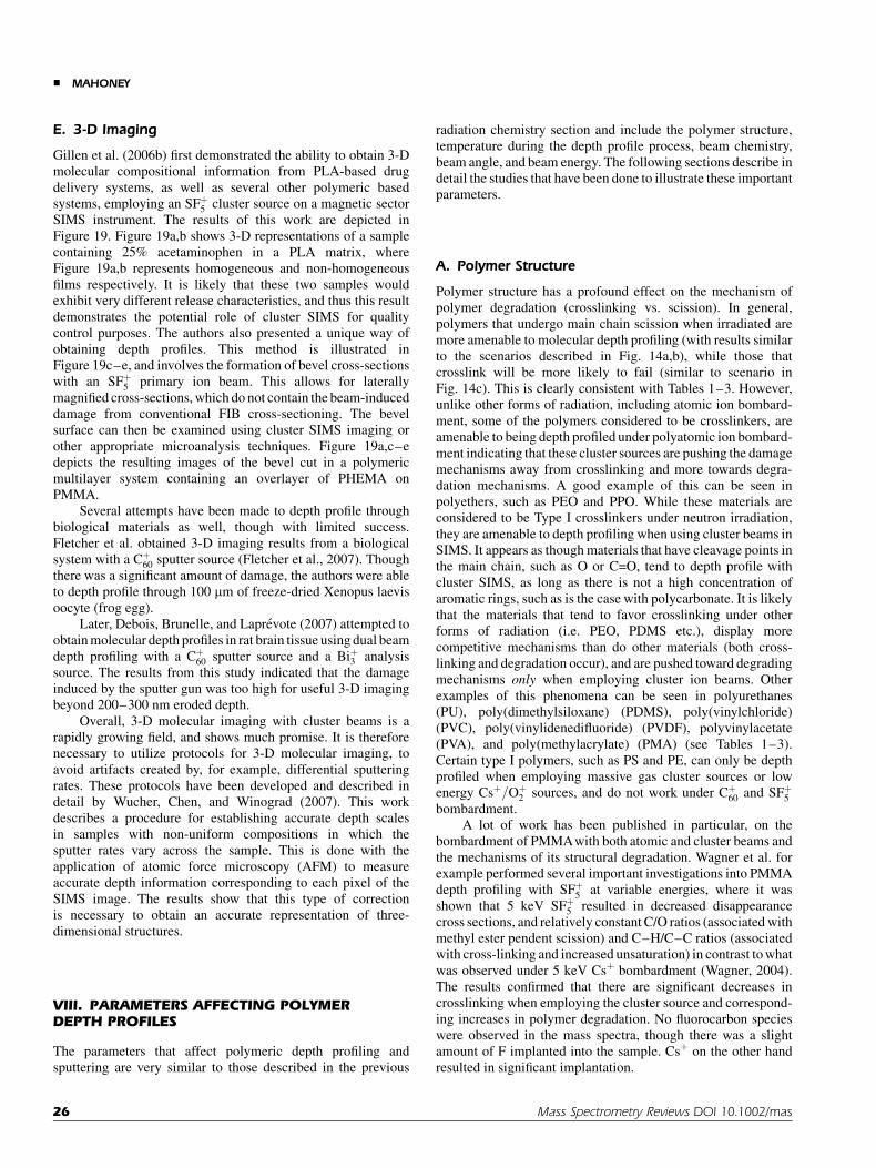
E. 3-D Imaging
Gillen et al. (2006b) first demonstrated the ability to obtain 3-Dmolecular compositional information from PLA-based drugdelivery systems, as well as several other polymeric basedsystems, employing an SFþ
5 cluster source on a magnetic sectorSIMS instrument. The results of this work are depicted inFigure 19. Figure 19a,b shows 3-D representations of a samplecontaining 25% acetaminophen in a PLA matrix, whereFigure 19a,b represents homogeneous and non-homogeneousfilms respectively. It is likely that these two samples wouldexhibit very different release characteristics, and thus this resultdemonstrates the potential role of cluster SIMS for qualitycontrol purposes. The authors also presented a unique way ofobtaining depth profiles. This method is illustrated inFigure 19c–e, and involves the formation of bevel cross-sectionswith an SFþ
5 primary ion beam. This allows for laterallymagnified cross-sections, which do not contain the beam-induceddamage from conventional FIB cross-sectioning. The bevelsurface can then be examined using cluster SIMS imaging orother appropriate microanalysis techniques. Figure 19a,c–edepicts the resulting images of the bevel cut in a polymericmultilayer system containing an overlayer of PHEMA onPMMA.
Several attempts have been made to depth profile throughbiological materials as well, though with limited success.Fletcher et al. obtained 3-D imaging results from a biologicalsystem with a Cþ
60 sputter source (Fletcher et al., 2007). Thoughthere was a significant amount of damage, the authors were ableto depth profile through 100 mm of freeze-dried Xenopus laevisoocyte (frog egg).
Later, Debois, Brunelle, and Laprevote (2007) attempted toobtain molecular depth profiles in rat brain tissue using dual beamdepth profiling with a Cþ
60 sputter source and a Biþ3 analysissource. The results from this study indicated that the damageinduced by the sputter gun was too high for useful 3-D imagingbeyond 200–300 nm eroded depth.
Overall, 3-D molecular imaging with cluster beams is arapidly growing field, and shows much promise. It is thereforenecessary to utilize protocols for 3-D molecular imaging, toavoid artifacts created by, for example, differential sputteringrates. These protocols have been developed and described indetail by Wucher, Chen, and Winograd (2007). This workdescribes a procedure for establishing accurate depth scalesin samples with non-uniform compositions in which thesputter rates vary across the sample. This is done with theapplication of atomic force microscopy (AFM) to measureaccurate depth information corresponding to each pixel of theSIMS image. The results show that this type of correctionis necessary to obtain an accurate representation of three-dimensional structures.
VIII. PARAMETERS AFFECTING POLYMERDEPTH PROFILES
The parameters that affect polymeric depth profiling andsputtering are very similar to those described in the previous
radiation chemistry section and include the polymer structure,temperature during the depth profile process, beam chemistry,beam angle, and beam energy. The following sections describe indetail the studies that have been done to illustrate these importantparameters.
A. Polymer Structure
Polymer structure has a profound effect on the mechanism ofpolymer degradation (crosslinking vs. scission). In general,polymers that undergo main chain scission when irradiated aremore amenable to molecular depth profiling (with results similarto the scenarios described in Fig. 14a,b), while those thatcrosslink will be more likely to fail (similar to scenario inFig. 14c). This is clearly consistent with Tables 1–3. However,unlike other forms of radiation, including atomic ion bombard-ment, some of the polymers considered to be crosslinkers, areamenable to being depth profiled under polyatomic ion bombard-ment indicating that these cluster sources are pushing the damagemechanisms away from crosslinking and more towards degra-dation mechanisms. A good example of this can be seen inpolyethers, such as PEO and PPO. While these materials areconsidered to be Type I crosslinkers under neutron irradiation,they are amenable to depth profiling when using cluster beams inSIMS. It appears as though materials that have cleavage points inthe main chain, such as O or C=O, tend to depth profile withcluster SIMS, as long as there is not a high concentration ofaromatic rings, such as is the case with polycarbonate. It is likelythat the materials that tend to favor crosslinking under otherforms of radiation (i.e. PEO, PDMS etc.), display morecompetitive mechanisms than do other materials (both cross-linking and degradation occur), and are pushed toward degradingmechanisms only when employing cluster ion beams. Otherexamples of this phenomena can be seen in polyurethanes(PU), poly(dimethylsiloxane) (PDMS), poly(vinylchloride)(PVC), poly(vinylidenedifluoride) (PVDF), polyvinylacetate(PVA), and poly(methylacrylate) (PMA) (see Tables 1–3).Certain type I polymers, such as PS and PE, can only be depthprofiled when employing massive gas cluster sources or lowenergy Csþ=Oþ
2 sources, and do not work under Cþ60 and SFþ
5
bombardment.A lot of work has been published in particular, on the
bombardment of PMMAwith both atomic and cluster beams andthe mechanisms of its structural degradation. Wagner et al. forexample performed several important investigations into PMMAdepth profiling with SFþ
5 at variable energies, where it wasshown that 5 keV SFþ
5 resulted in decreased disappearancecross sections, and relatively constant C/O ratios (associated withmethyl ester pendent scission) and C–H/C–C ratios (associatedwith cross-linking and increased unsaturation) in contrast to whatwas observed under 5 keV Csþ bombardment (Wagner, 2004).The results confirmed that there are significant decreases incrosslinking when employing the cluster source and correspond-ing increases in polymer degradation. No fluorocarbon specieswere observed in the mass spectra, though there was a slightamount of F implanted into the sample. Csþ on the other handresulted in significant implantation.
& MAHONEY
26 Mass Spectrometry Reviews DOI 10.1002/mas

There were also significant increases in peaks characteristicof polycyclic aromatic hydrocarbons (PAH’s) after bombardmentwith Csþ as compared to SFþ
5 . The existence of such peaks isconsistent with what has been observed previously with atomicion bombardment under higher ion fluences (Briggs & Hearn,1986; Hearn & Briggs, 1988; Van Ooij & Brinkhuis, 1988;Leggett & Vickerman, 1992) and is associated with increasedbeam damage to the sample. Essentially, the material becomesincreasingly unsaturated, until cyclic structures are formedand ultimately aromatic units such as the cyclic tropylium ionat m/z¼ 91 ðC7Hþ
7 Þ (Briggs & Hearn, 1986) are observed. Thiscyclization is known to occur under other forms of irradiation aswell (Chapiro, 1962) and is consistent with the graphitic nature ofhighly damaged surfaces.
Temperature also plays a very important role in themechanisms of degradation in PMMA, where at high temper-atures, ion-induced depolymerization mechanisms dominate.Conversely, at low temperatures, the data is consistent with asignificant decrease in crosslinking (Mahoney et al., 2006a;Mahoney, Patwardhan, & McDermott, 2006b; Mahoney, Fahey,& Gillen, 2007a; Mahoney et al., 2007b; Mahoney, Fahey, &Belu, 2008). These temperature effects will be described ingreater detail later.
The overall degradation mechanism of PMMA whenirradiated by cluster ion beams is illustrated in Scheme 1, whichshows the possible degradation routes under variable conditions.The degradation pathways shown in Scheme 1 represents asummary from several references (Hearn & Briggs, 1988;Leggett & Vickerman, 1992; Van Ooij & Brinkhuis, 1988;Briggs & Hearn, 1986; Bermudez, 1999; Wagner, 2004;Mahoney, Fahey, & Gillen, 2007a; Mahoney et al., 2007b). Theroute of degradation is best described as a two-step degradationprocess, starting first with the loss of the methyl ester pendentgroup. This is immediately followed by main chain scissionoccurring at low fluences, and eventual crosslinking andunsaturation at higher fluences. The fluence at which thiscrosslinking occurs varies with the type of source used, and the
conditions under which the source is operated (e.g., temperature,beam energy). While atomic sources will tend to cause cross-linking of the sample almost immediately, polyatomic sources,such as SFþ
5 and Cþ60 exhibit delayed crosslinking of the sample,
making depth profiling feasible. Cþ60, particularly at higher
energies, tends to be a better performer in terms of preventingcrosslinking, where signal can be maintained for much higherprimary ion fluences as compared to SFþ
5 (Fisher et al., 2008).Wagner performed several investigations into the effect
of polymer structure on sputtering mechanisms in a seriesof publications that further demonstrates the importance ofchemical structure on damage accumulation during depthprofiling of methacrylics (Wagner, 2005a,b,c). As can be seenfrom Table 3, all of these profiles are considered to be‘‘successful’’ to some degree. However, when we say that amaterial is ‘‘successful’’, we mean that we can to some degree,maintain molecular signal characteristic of the polymer as afunction of depth. Whether or not there is a more gradualdegradation of signal or a limitation in depth is not included inthis table, as it most likely varies with cluster source selectionand/or other experimental conditions. The first article in thisseries was a systematic study of the effect of exchanging mainchain and side-chain methyl groups on the resulting SFþ
5 depthprofiles, by comparing PMMA, PMA, and PMAA (Wagner,2005a). The structures of the three different polymers differ onlyin their placement of a methyl group (see Table 3), where thePMA has the methyl group on the side chain only, the PMAA, hasit on the main chain only and the PMMA has the methyl groups inboth places. Overall the highest sputter rates and signalconstancies were obtained from PMMA, though all weresuccessfully profiled with SFþ
5 to some degree. The sputter ratesfor PMMA were reported to be approximately twice as high asthat obtained for PMA and PMAA under identical sputteringconditions.
The theory behind this change in sputter properties wasdiscussed in reference to the known degradation pathways of thedifferent materials. In particular, PMA is more likely to crosslink
SCHEME 1. Mechanism of PMMA degradation under ion bombardment.
CLUSTER SECONDARY ION MASS SPECTROMETRY &
Mass Spectrometry Reviews DOI 10.1002/mas 27
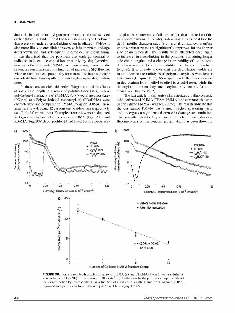
due to the lack of the methyl group on the main chain as discussedearlier (Note, in Table 3, that PMA is listed as a type I polymerthat prefers to undergo crosslinking when irradiated). PMAA isalso more likely to crosslink however, as it is known to undergodecarboxylation and subsequent intermolecular crosslinking.It was theorized that the polymers that undergo thermal orradiation-induced decomposition primarily by depolymeriza-tion, as is the case with PMMA, maintain strong characteristicsecondary ion intensities as a function of increasing SFþ
5 fluence,whereas those that can potentially form intra- and intermolecularcross-links have lower sputter rates and higher signal degradationrates.
In the second article in this series, Wagner studied the effectsof side-chain length in a series of poly(methacrylates), wherepoly(n-butyl methacrylate) (PBMA), Poly(n-octyl methacrylate)(POMA) and Poly(n-dodecyl methacrylate) (PDoDMA) werecharacterized and compared to PMMA (Wagner, 2005b). Thesematerials have 4, 8, and 12 carbons on the side-chain respectively(see Table 3 for structures). Examples from this work are depictedin Figure 20 below which compares PBMA (Fig. 20a) andPDoMA (Fig. 20b) depth profiles (4 and 10 carbons respectively)
and plots the sputter rates of all these materials as a function of thenumber of carbons in the alkyl side-chain. It is evident that thedepth profile characteristics (e.g., signal constancy, interfacewidths, sputter rates) are significantly improved for the shorterside chain materials. The results were attributed once againto increases in cross-linking in the polymers containing longerside-chain lengths, and a change in probability of ion-induceddepolymerization (lower probability for longer side-chainlengths). It is already known that the degradation yields aremuch lower in the radiolysis of polymethacrylates with longerside chains (Chapiro, 1962). More specifically, there is a decreasein degradation from methyl to ethyl to n-butyl ester, while thedodecyl and the octadecyl methacrylate polymers are found tocrosslink (Chapiro, 1962).
The last article in this series characterizes a trifluoro aceticacid-derivatized PMMA (TFAA-PMMA) and compares this withunderivatized PMMA (Wagner, 2005c). The results indicate thatthe derivatized PMMA has a much higher sputtering yieldand undergoes a significant decrease in damage accumulation.This was attributed to the presence of the electron-withdrawingfluorine atoms on the pendant group, which has been shown to
FIGURE 20. Positive ion depth profiles of spin-cast PBMA (a), and PDoMA (b) on Si wafer substrates.
Sputter beam¼ 5 keV SFþ5 analysis beam¼ 10 keVArþ. (c) Sputter rates for the positive ion depth profiles of
the various poly(alkyl methacrylates) as a function of alkyl chain length. Figure from Wagner (2005b),
reprinted with permission from John Wiley & Sons, Ltd, copyright 2005.
& MAHONEY
28 Mass Spectrometry Reviews DOI 10.1002/mas

weaken the polymer backbone in radiation studies, increasing theprobability of main-chain scission or depolymerization underSFþ
5 bombardment.Wagner was also able to demonstrate molecular depth
profiling in polymer multilayer thin films of various methacrylics(Wagner, 2005d). The multilayer samples characterized con-sisted of bilayers and trilayers of PMMA, PHEMA, and TFAA-PHEMA. The overall results of this study indicated that theordering of the layers was important and affected the damageaccumulation in the profile, similar to what was observedby Kozole et al. (2006). In particular, when PHEMA was theoutermost layer, there was a reduction in sputter rates for theunderlying polymer layer. This was attributed to increased ion-induced damage accumulation rates in PHEMA, which carriesthrough to the next layer.
The effect of increased crosslinking on depth profilability isalso consistent with results obtained later on, by Wagner et al.(2006), displayed in Figures 21 and 22. In this work, Wagner wasable to demonstrate that when increasing the amount ofcrosslinking in PMMA (by adding increased amounts ofthe crosslinker EGDMA during the polymerization) there is acorresponding decrease in sputter rate and increased damageaccumulation. This work stems from early experiments involvingsurface analysis of such materials, where changes in the peakintensities of atomic versus molecular secondary ions wereobserved as a function of cross-linker concentration (Chilkotiet al., 1993), indicating a loss in signal with increasing crosslinkercontent.
To summarize, one can predict the success of polymericdepth profiling based on its structure. The following rules apply:
Rule 1: Type I (crosslinking) polymers are less likely to retainmolecular information as a function of depth, even withcluster sources.
Rule 2: All or most Type II (degrading) polymers are likely toretain molecular information as a function of depth.
Rule 3: Polymers that have increased strain on the main chainbackbone, due to the existence of quaternary C structuresand/or stereochemistry changes (discussed later) are morelikely to retain molecular information as a function ofdepth.
Rule 4: Any sample with a cleavage point in the main chain,whether or not it is type I or type II, is more likely to retainmolecular information as a function of depth (e.g., –O–,–COO–, –NH-CO–).
Rule 5: Halogen-containing polymers are more likely toretain molecular information as a function of depth dueto an enhanced chemical etching.
Rule 6: Polymers that are particularly susceptible todepolymerization mechanisms are more likely to retainmolecular information as a function of depth. Polyestersare particularly successful because of this.
Rule 7: Increased aromaticity results in a decreased abilityto retain molecular information as a function of depth,due to the protection of the resonance stabilizedstructures.
Rule 8: Many of the difficulties with Type I crosslinkingpolymers, such as PS, PE, PC, and PP can be alleviated byusing low energy Csþ and/or Oþ
2 atomic and diatomic ions,
which have shown to outperform SFþ5 and Cþ
60 clustersources for these particular cases (Mine et al., 2007).Moreover, gas cluster sources have recently been shown tooutperform all beams (clusters and atomics) for depthprofiling of type I polymers.
Rule 9: Even though a polymer retains molecular informationas a function of depth to some degree, the maximumachievable erosion depths and signal constancy will varywith chemical structure, cluster source used, temperature,beam angle, and other experimental variables definedherein.
B. Polyatomic Ion
After SFþ5 and C�
8 were shown to be feasible for molecular depthprofiling applications (Gillen & Roberson, 1998; Gillen et al.,2001), several other probes were investigated as tools as well. Cþ
60
was demonstrated to be useful for polymeric depth profiling in2004, when depth profiling in PMMA was performed with a Cþ
60
probe (Szakal et al., 2004), and since then has been usedrepeatedly. Another source demonstrated to be useful for depthprofiling in polymeric materials is Ir4ðCOÞþ7 which has recentlybeen proven to profile through thin PMMA overlayers (Fujiwaraet al., 2006). More recently, gas cluster sources (e.g., Ar3000) havebeen shown to be useful for depth profiling in polymers as well(55th American Vaccum Society International Symposium andExhibition, October 19th–24th, 2008). The question one needs toask therefore is obvious. Are all sources equal in terms of depthprofiling?
1. Interface Width Measurements
Before discussing this issue, it is important to point out, that onehas to be careful when making comparisons between resultsreported in the literature, because there is a lack of commonterminology and standardized methods. A good example ofliterature inconsistencies can be seen in definitions of interfacewidths and sputter rates. Definitions for interface widths forexample, range from that defined by ASTM standard methodE1438,5 to those which take into account the different sputterrates of the materials at the interface, similar to what is done insemiconductor metrology (Wagner, 2004). Some of the morerecently published works do not even define how their interfacewidths are measured. This can be a huge problem whencomparing sources and needs to be standardized. A goodexample of the differences can be illustrated by comparingvalues reported by Wagner (2004), who reports an interface widthfor PMMA on Si to be approximately 28 nm when accounting fordifferential sputter rates in the interfacial region, and Mahoney,Roberson, and Gillen (2004), who reports the interface width ofthe same sample, under the same conditions to be 60.9� 3.4 nmwhen employing only polymer sputter rates to describe interfacefeatures.
————5ASTM Standard Guide for Measuring Widths of Interfaces in Sputter
Depth Profiling Using SIMS: Designation E 1438-91.
CLUSTER SECONDARY ION MASS SPECTROMETRY &
Mass Spectrometry Reviews DOI 10.1002/mas 29
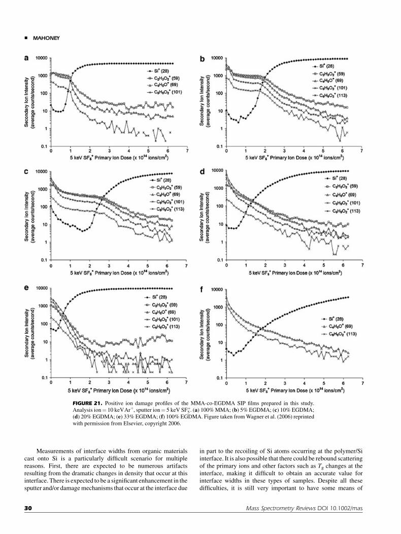
Measurements of interface widths from organic materialscast onto Si is a particularly difficult scenario for multiplereasons. First, there are expected to be numerous artifactsresulting from the dramatic changes in density that occur at thisinterface. There is expected to be a significant enhancement in thesputter and/or damage mechanisms that occur at the interface due
in part to the recoiling of Si atoms occurring at the polymer/Siinterface. It is also possible that there could be rebound scatteringof the primary ions and other factors such as Tg changes at theinterface, making it difficult to obtain an accurate value forinterface widths in these types of samples. Despite all thesedifficulties, it is still very important to have some means of
FIGURE 21. Positive ion damage profiles of the MMA-co-EGDMA SIP films prepared in this study.
Analysis ion¼ 10 keVArþ, sputter ion¼ 5 keV SFþ5 . (a) 100% MMA; (b) 5% EGDMA; (c) 10% EGDMA;
(d) 20% EGDMA; (e) 33% EGDMA; (f) 100% EGDMA. Figure taken from Wagner et al. (2006) reprinted
with permission from Elsevier, copyright 2006.
& MAHONEY
30 Mass Spectrometry Reviews DOI 10.1002/mas

measuring and comparing relative interfacial widths in thesesystems, as it is a means of optimizing the source andexperimental conditions. The following explains, from theauthors’ perspective, when one should employ each method ofmeasuring interface widths.
1. Standard method ASTM E1428-91 uses the followingequation; DZ¼ [Dt/t]*Z, where DZ is the interface width,Dt is the sputtering time required for a decrease in thesignal intensity of the overlayer from 84% to 16% of thesignal intensity (or an increase in the substrate from 16%to 84%), t is the time required to sputter through theoverlayer as defined by the time at which the overlayer (orsubstrate) signal intensity reaches 50% of its maximumvalue, and Z is the measured thickness of the overlayer.This method is should only be used as a relative measure ofinterface widths and only for; (a) polymeric samples thathave constant sputter rates throughout the depth of theoverlayer, and (b) minimal interlayer mixing occurring,such as certain ‘‘well-behaved’’ polymers cast on Sisubstrates. Even in these cases, this method should only beused as an approximation of interfacial widths. So for aPLA sample deposited on Si for example, this is an idealmethod for interface width approximation, as PLA hasrapid sputter rates that tend to be constant with increasingfluence (Mahoney, Roberson, & Gillen, 2004; Shard et al.,2008). However, it is not quite as useful for samples whichcrosslink quicker, such as is the case with thicker films ofPMMA sputtered with SFþ
5 in which the sputter ratedecreases significantly prior to the interface (Mahoneyet al., 2006a). In the latter case, the result reported byASTM will tend to result in an overestimated interfacewidth. The width in this case should be measured afterconversion of the profile to a depth scale using measuredpolymer sputter rates in the interfacial region. This methodshould also not be used for materials in which there will beconsiderable interfacial mixing, as would be the case inpolymeric multilayers.
2. The method that is used to account for interlayer mixinguses a weighted average sputter rate between the substrateand the overlayer signal. The equation is shown below:
SRoverall ¼Isub
Isubmax
� �SRsub þ 1� Isub
Isubmax
� �SRpolymer ð4Þ
where SRoverall is the weighted average sputter rate, Isub isthe intensity of the signal characteristic of the substrate at agiven time, Isubmax, is the substrate maximum, afterthe overlayer has been removed, SRsub is the sputter rateof the substrate material, and SRpolymer is the sputter rateof the polymer. This weighted average sputter rate is thenused to convert the profile to a depth scale, and theinterlayer thickness is measured based on the interfacewidth guidelines described above (84%/16% maximumsubstrate intensity). In cases where there are multilayers ofsoft materials, this is the preferred method. However, thisequation is not accurate in cases where there is negligibleinterlayer mixing, and where the densities and sputterrates of the substrate are strikingly different than that ofthe coating by 2 or more orders of magnitude, such as isthe case of thin polymer films on Si. The sputtering yield ofSi, for example is extremely low as compared to mostpolymers. Under similar sputtering conditions (SFþ
5 at5 keV), the following sputtering yields have been reported(Mahoney, Roberson, & Gillen, 2004; Wagner, 2004): Sisputtering yield¼ 0.1 nm3/ion, PMMA sputteringyield¼ 20 nm3/ion and PLA sputtering yield¼ 60 nm3/ion. This is over a factor of 200 decrease in sputtering yieldfrom the organic to the Si interface! Therefore, anysputtering of Si is negligible during the removal of thepolymer overlayers. In such cases, the result reported bythis method, will result in an underestimated interfacewidth. The width therefore in these cases should bemeasured after conversion of the profile to a depth scaleusing known polymer sputter rates at the interface. A goodexample of this underestimation is the interface widthscalculated in Mahoney’s work for PLA. The interfacewidths were calculated to be approximately 11 nm ascalculated by conversion to a depth scale with known PLAsputter rates (Mahoney, Roberson, & Gillen, 2004).However, when the weighted sputter rate method wasapplied to these same systems, one achieves a depthresolution of only 3 nm!
It is not likely that a significant amount of interlayermixing is occurring in thin ‘‘well-behaved’’ films on Sidue to the huge differences in their densities, although it iscertainly expected that some Si will rebound back into thepolymer. However, this will cause either enhancedsputtering yields (in ‘‘well-behaved’’ systems) or signifi-cant chemical damage at the interface (in polymersexhibiting moderate to extreme crosslinking). Inthe second case, the sputter rate at the interface is expectedto be reduced because the material being removed from theinterface is a highly damaged overlayer with significantlyreduced sputter rates as compared to the original polymer.In such cases, there is a slightly increased probability of
FIGURE 22. Sputter rates of the EGDMA-co-MMA SIP films under 5
keV SFþ5 bombardment. Figure taken from Wagner et al. (2006)
reprinted with permission from Elsevier, copyright 2006.
CLUSTER SECONDARY ION MASS SPECTROMETRY &
Mass Spectrometry Reviews DOI 10.1002/mas 31

interfacial mixing, but the interface width measurementsshould be based on the actual sputtering rates observed atthe interface.
More recent work has been published on the preparationof model multilayer films, which can serve as organic‘‘delta-layers’’ (commonly used reference samples fordynamic SIMS in the semiconductor industry), thusallowing for more direct comparisons (Shard et al.,2008; Zheng, Wucher, & Winograd, 2008). In these films,the sputter rates and densities of the materials are verysimilar such that accurate depth resolutions can beobtained and compared.
3. There are still arguments as to whether the rise of thesubstrate signal or the fall of the organic signal should beused to define the interface widths. For now, this decisionmay need to be made on a case by case basis. In mostworks, the properties of the Si substrate signal have beenused to define interface locations and widths. However,more recently, it is being discovered that this may not bethe best way to make these measurements, as there islikely to be an interfacial damage layer (graphitic innature) existing between the organic film and the Sisubstrate (Mahoney, 2009). The influence of this layer isdependent upon the sample and experimental conditions.In samples that do not accumulate damage before theinterface is reached (PLA, for example) this may notcontribute much to the interface measurements. However,in samples where damage starts accumulating prior tothe interface (e.g., thicker films, or samples exhibitingincreased crosslinking), this damage layer causes areduced sputter rate at the interface which in turn resultsin significant broadening of the Si width, and a shift in thelocation of the interface towards higher ion fluences withrespect to the location as defined by the organic signaldecay. These interface effects can not be accounted for byemploying differential sputtering rates.
Similar shifts in interface locations have been found byGreen et al. (2009) in depth profiles of Irganox on Si. Inthis case, the authors found that the choice of ion (i.e., Si�x ,Si�H, or SiO�
2 ) used to define the organic/Si interface playsa very important role. More specifically, the authorsillustrated that the presence of the SiO2 layer wasparticularly problematic and resulted in artificial broad-ening of the interface when employing the Si�x signals as ameans to characterize the interface (Green et al., 2009). Itis possible that the same sorts of effects are observed whenemploying Siþ ions in the positive mode as well.
Another potential problem with using the Si side forcharacterization of interface properties is that somesources, such as SFþ
5 , may cause non-linear Siþ ion yieldenhancements, making for unreliable interface propertymeasurements. Alternatively, the decline of the polymersignal can also be a source of error, as it is difficult todecide where the maximum polymer signal is located,especially in a case where there is a steady decline insignal.
Either method requires direct measurements of thesputter rates at the interface, to obtain more accuratesputter rate information. The sputtering yields at the
interface can be measured via a quartz crystal micro-balance (QCM) for example. In addition, film preparationshave to be optimized, such that there are no ripples in thepolymer films, and/or the raw data manipulated such thatthe depth profile is obtained only in common areas of thefilm where the thickness is consistent (Wucher, 2008;Mahoney, 2009).
2. C60 Versus SFþ5
Taking the above notions into consideration, it can be stated thatCþ
60 is an ideal source for depth profiling through thickerpolymeric layers (Fisher et al., in press), as the signal tends toremain stable for much higher fluences, and has comparablyhigher sputtering yields. The following approximate sputteringyields were reported for PLA under varying conditions for bothSFþ
5 and Cþ60:
. 250 nm3=Cþ60 at 30 keV (500 eV per atom) (Shard et al.,
2007).. 75 nm3=Cþ
60 at 20 keV (333 eV per atom) (Shard et al.,2007).
. 40 nm3=Cþ60 at 10 keV (167 eV per atom) (Shard et al.,
2007).. 40 � 59 nm3=SFþ
5 at 5 keV (833 eV average energy peratom) (Mahoney, Roberson, & Gillen, 2004; Mahoney, Yu,& Gardella, 2005).
Similarly for PMMA, the sputtering yields are reported asfollows:
. 38 nm3=Cþ60 at 10 keV (167 eV per atom) (Mollers et al.,
2006).. 20 nm3=SFþ
5 at 5 keV (833 eV average energy per atom)(Wagner, 2004; Mahoney et al., 2007a).
. 65 nm3=SFþ5 at 8.75 keV (1,460 eV average energy per
atom) (Wagner, 2004).. 8 nm3=SFþ
5 at 2.5 keV (417 eV average energy per atom)(Wagner, 2004).
As can be seen in both cases, the sputtering yields are muchhigher for Cþ
60, even at lower energies per atom.Despite the obvious successes of Cþ
60 bombardment ofpolymeric materials, deposition of carbon and large topographyfeatures can be associated with Cþ
60 beams at lower energies(Fahey et al., 2006; Gillen et al., 2006a; Green et al., 2009). Thisis a particular problem with Si substrates, which is often usedas a support for polymer thin films. These factors may result indegradation of the depth resolution. SFþ
5 tends to exhibitexcellent depth resolution, and also tends to be well-rounded inits uses for both organic and inorganic applications, but cannotattain the depths that Cþ
60 has achieved, even when lowtemperatures are applied. From comparison of PLA depthprofiles and other comparisons obtained in the literature thusfar, it appears to be that SFþ
5 may have slightly improved depthresolutions as compared to Cþ
60 (Mahoney, Roberson, & Gillen,2004; Shard et al., 2007) although it is too early to confirm at thisjuncture.
& MAHONEY
32 Mass Spectrometry Reviews DOI 10.1002/mas

3. Massive Gas Clusters
Even more recently, data has been presented which indicates thatmassive gas clusters can achieve even greater sampling depthsthan Cþ
60. In addition, unlike Cnþ60 and SFþ
5 , these gas clustersources have been shown to work well for both type I and type IIpolymers.
4. LMIG Clusters
LMIG clusters have been demonstrated to profile through thinorganic layers, but do so very poorly as compared to SFþ
5 or Cþ60.
For example, the damage characteristics of PET under Auþ3 and
Cþ60 ion bombardment were studied in detail by Conlan et al.
(2006). In this study, the authors plotted the relative intensity ofselected PET secondary ions as a function of increasing primaryion fluence. It was found that damage accumulated under Aucluster bombardment (signal decreased with fluence), but notunder Cþ
60 bombardment, which maintained relatively constantsignals with increasing fluence. Similar results were found inother kinds of molecular samples, such as trehalose (Cheng et al.,2007). Finally, the sputter rates were found to be enhancedsignificantly for PS 2000 when employing Cþ
60 ion beams asopposed to Auþ3 beams (Hill & Blenkinsopp, 2004).
C. Beam Energy
It has been repeatedly demonstrated, that increasing cluster beamenergies generally results in increases in sputter and secondaryion yields in organic and polymeric samples (Wagner, 2004;Bolotin, Tetzler, & Hanley, 2006; Fletcher et al., 2006a; Shardet al., 2007). A nice example is shown below in a plot taken fromShard et al. (2007), which shows the sputtering yield volumes forPLA, Irganox 1010 and Alq3 samples as a function of Cþ
60 beamenergy (see Fig. 23).
More recently it has been determined (Fisher et al., 2008)that as the C60 beam energy increases, one can maintainmolecular secondary ions for longer sputter times, or increasedsputtered depths into the sample. Figure 24, displays thenormalized intensities of m/z¼ 85 and m/z¼ 185 (peakscharacteristic of PMMA) as a function of increasing depth for10, 20, and 40 keV Cnþ
60 ion bombardment of bulk PMMA. Theresults indicate that signal loss occurs much later with the higherenergy beams. These results are consistent with previous workwith atomic bombardment which showed that the efficiencies ofthe damage processes (e.g., crosslinking, etc) are lower for high-energy ions than for low energy ions (Calcagno, 1995). However,it is also likely that the onset of damage accumulation at lowerenergies with C60 is actually brought about by deposition ofcarbon, rather than crosslinking. Therefore it is not clear at thispoint whether the same effects would be observed for otherbeams as well.
The topography, modulus and chemistry of the craterbottoms were subsequently measured using nanoindentationand XPS. Roughness was found to increase with beam energy,
FIGURE 23. Yield volumes for PLA (^), Irganox 1010 (&), and Alq3
as a function of primary ion energy. The initial (~), and final (~) yield
volumes for Alq3 are provided. Figure taken from Shard et al. (2007)
reprinted with permission from John Wiley & Sons, Ltd, copyright 2007.
FIGURE 24. Negative TOF–SIMS depth profiles of bulk PMMA
generated using 10 keV Cþ60 (green), 20 keV Cþ
60 (blue) and 40 keV
Cþþ60 (red) primary ions for both sputtering and acquisition.
(A) Normalized counts at 85 m/z plotted against sputter depth. (B)
Normalized counts at 185 m/z plotted against sputter depth. Figure taken
from Fisher et al. (Fisher et al., 2008) reprinted with permission from
Elsevier, copyright 2008. [Color figure can be viewed in the online issue,
which is available at www.interscience.wiley.com.]
CLUSTER SECONDARY ION MASS SPECTROMETRY &
Mass Spectrometry Reviews DOI 10.1002/mas 33

with peak to peak roughness values of 6 nm for the surface, 57 nmfor the 10 keV Cþ
60 crater bottom, 183 nm for 20 keV Cþ60 crater
bottom, and 309 nm for 40 keV Cþþ60 crater bottom. This
increased roughness was attributed to defects in the PMMA film.These are fairly high values for topography formation, and hencethere should be a corresponding decrease in depth resolution athigher energies. The hardness and modulus were found todecrease with increasing beam energy. The XPS spectra alsoindicated decreased O concentrations and decreased C=Ocontent with increasing energy. Although these changes couldbe attributed to increased damage accumulation at higherenergies resulting from the longer sputtering times, it could alsobe attributed to C deposition.
More recently, alternating layers of two different Irganoxsamples were prepared as a means to create model organic‘‘delta-layers’’ (Shard et al., 2008). The results from this work aresimilar to that observed by Fisher et al. (2008) in that there isevidence of decreased erosion depths for lower energy beams,and increased roughness at higher energies. The correspondingdepth resolutions however were determined to be greater at lowerenergies.
D. Beam Angle
It has recently been demonstrated that glancing ion beam anglesare most ideal for organic and polymeric depth profiling with Cþ
60
beams due to a reduction in penetration depths (Kozole, Wucher,& Winograd, 2008; Miyayama et al., 2008). Kozole et al. showthat there is a reduction in molecular damage at more glancingangles, even though the total sputtering yield is reduced.Figure 25 illustrates this important result in a thin film ofcholesterol on Si. These results suggest reduced damage is notnecessarily dependent upon enhanced sputtering yields and thatdepositing the incident energy nearer the surface by using
glancing angles is most important. It is unclear at this point ifcarbon deposition plays a role as well.
E. Charge
Szymczak and Wittmaack (Szymczak & Wittmaak, 1994)acquired positive and negative TOF mass spectra of Si sputter-cleaned with SF�
6 , SF�5 , SFþ
5 , and Xeþ. Charge was found to playlittle, if any, role in the ion yields. Several investigations use Cþ
60,C2þ
60 , and C3þ60 interchangeably for depth profiling applications
(Shard et al., 2007; Wucher, Chen, & Wingorad, 2008; Fisheret al., 2008) with very little difference in the results. Therefore itis assumed that charge does not play a significant role in depthprofiling.
F. Oxygen Flooding
Recent studies have indicated that oxygen flooding duringpolymeric depth profiling can enhance secondary ion yieldsduring depth profiling, but only slightly. To the author’sknowledge, there has not yet been a publication in regards tothe maximum erosion depths achievable with and withoutoxygen flooding. Though the presence of oxygen duringirradiation has been shown to enhance degradation mechanismsin some polymers (Chapiro, 1962), the pressures are most likelytoo low during a typical SIMS experiment to have anyappreciable affect. In either case, more work needs to be donein this area before the issue can be discussed further.
G. Temperature
Because most crosslinking and degradation mechanisms relyheavily on the formation of free radical intermediates, temper-ature and crystallinity typically play a very important role in the
FIGURE 25. Depth profile plots of cholesterol quasi-molecular ion (m/z 369, [M–H2O]þ; squares) and
silicon (m/z 28, Siþ; triangles) ion intensities as a function of Cþ60 fluence. The depth profiles were acquired
using 40 keV Cþ60 at 58, (a) 258 and (b) 738 incidence. The Si intensity is multiplied by a factor of 10 in each
depth profile plot. Figure taken from Kozole, Wucher, and Winograd (2008) reprinted with permission from
American Chemical Society, copyright 2008. [Color figure can be viewed in the online issue, which is
available at www.interscience.wiley.com.]
& MAHONEY
34 Mass Spectrometry Reviews DOI 10.1002/mas
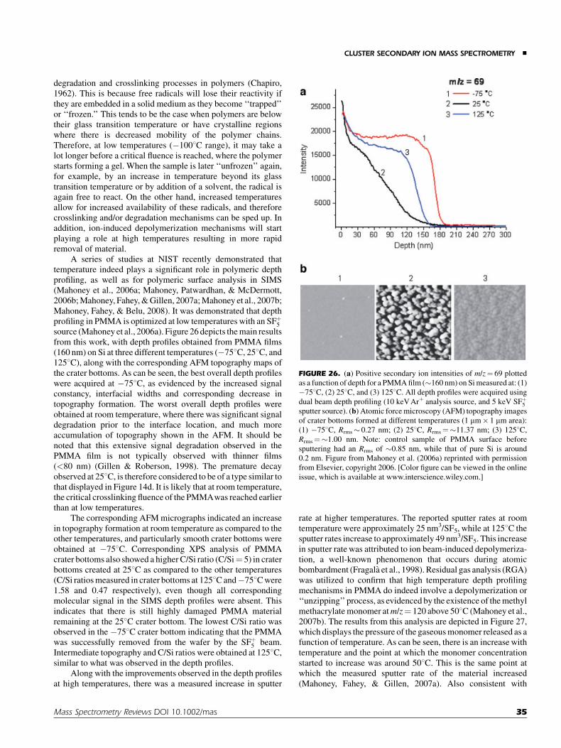
degradation and crosslinking processes in polymers (Chapiro,1962). This is because free radicals will lose their reactivity ifthey are embedded in a solid medium as they become ‘‘trapped’’or ‘‘frozen.’’ This tends to be the case when polymers are belowtheir glass transition temperature or have crystalline regionswhere there is decreased mobility of the polymer chains.Therefore, at low temperatures (�1008C range), it may take alot longer before a critical fluence is reached, where the polymerstarts forming a gel. When the sample is later ‘‘unfrozen’’ again,for example, by an increase in temperature beyond its glasstransition temperature or by addition of a solvent, the radical isagain free to react. On the other hand, increased temperaturesallow for increased availability of these radicals, and thereforecrosslinking and/or degradation mechanisms can be sped up. Inaddition, ion-induced depolymerization mechanisms will startplaying a role at high temperatures resulting in more rapidremoval of material.
A series of studies at NIST recently demonstrated thattemperature indeed plays a significant role in polymeric depthprofiling, as well as for polymeric surface analysis in SIMS(Mahoney et al., 2006a; Mahoney, Patwardhan, & McDermott,2006b; Mahoney, Fahey, & Gillen, 2007a; Mahoney et al., 2007b;Mahoney, Fahey, & Belu, 2008). It was demonstrated that depthprofiling in PMMA is optimized at low temperatures with an SFþ
5
source (Mahoney et al., 2006a). Figure 26 depicts the main resultsfrom this work, with depth profiles obtained from PMMA films(160 nm) on Si at three different temperatures (�758C, 258C, and1258C), along with the corresponding AFM topography maps ofthe crater bottoms. As can be seen, the best overall depth profileswere acquired at �758C, as evidenced by the increased signalconstancy, interfacial widths and corresponding decrease intopography formation. The worst overall depth profiles wereobtained at room temperature, where there was significant signaldegradation prior to the interface location, and much moreaccumulation of topography shown in the AFM. It should benoted that this extensive signal degradation observed in thePMMA film is not typically observed with thinner films(<80 nm) (Gillen & Roberson, 1998). The premature decayobserved at 258C, is therefore considered to be of a type similar tothat displayed in Figure 14d. It is likely that at room temperature,the critical crosslinking fluence of the PMMAwas reached earlierthan at low temperatures.
The corresponding AFM micrographs indicated an increasein topography formation at room temperature as compared to theother temperatures, and particularly smooth crater bottoms wereobtained at �758C. Corresponding XPS analysis of PMMAcrater bottoms also showed a higher C/Si ratio (C/Si¼ 5) in craterbottoms created at 258C as compared to the other temperatures(C/Si ratios measured in crater bottoms at 1258C and�758C were1.58 and 0.47 respectively), even though all correspondingmolecular signal in the SIMS depth profiles were absent. Thisindicates that there is still highly damaged PMMA materialremaining at the 258C crater bottom. The lowest C/Si ratio wasobserved in the �758C crater bottom indicating that the PMMAwas successfully removed from the wafer by the SFþ
5 beam.Intermediate topography and C/Si ratios were obtained at 1258C,similar to what was observed in the depth profiles.
Along with the improvements observed in the depth profilesat high temperatures, there was a measured increase in sputter
rate at higher temperatures. The reported sputter rates at roomtemperature were approximately 25 nm3/SF5, while at 1258C thesputter rates increase to approximately 49 nm3/SF5. This increasein sputter rate was attributed to ion beam-induced depolymeriza-tion, a well-known phenomenon that occurs during atomicbombardment (Fragala et al., 1998). Residual gas analysis (RGA)was utilized to confirm that high temperature depth profilingmechanisms in PMMA do indeed involve a depolymerization or‘‘unzipping’’ process, as evidenced by the existence of the methylmethacrylate monomer atm/z¼ 120 above 508C (Mahoney et al.,2007b). The results from this analysis are depicted in Figure 27,which displays the pressure of the gaseous monomer released as afunction of temperature. As can be seen, there is an increase withtemperature and the point at which the monomer concentrationstarted to increase was around 508C. This is the same point atwhich the measured sputter rate of the material increased(Mahoney, Fahey, & Gillen, 2007a). Also consistent with
FIGURE 26. (a) Positive secondary ion intensities of m/z¼ 69 plotted
as a function of depth for a PMMA film (�160 nm) on Si measured at: (1)
�758C, (2) 258C, and (3) 1258C. All depth profiles were acquired using
dual beam depth profiling (10 keV Arþ analysis source, and 5 keV SFþ5
sputter source). (b) Atomic force microscopy (AFM) topography images
of crater bottoms formed at different temperatures (1 mm� 1 mm area):
(1) �758C, Rrms� 0.27 nm; (2) 258C, Rrms¼�11.37 nm; (3) 1258C,
Rrms¼�1.00 nm. Note: control sample of PMMA surface before
sputtering had an Rrms of �0.85 nm, while that of pure Si is around
0.2 nm. Figure from Mahoney et al. (2006a) reprinted with permission
from Elsevier, copyright 2006. [Color figure can be viewed in the online
issue, which is available at www.interscience.wiley.com.]
CLUSTER SECONDARY ION MASS SPECTROMETRY &
Mass Spectrometry Reviews DOI 10.1002/mas 35

depolymerization was the XPS C1s spectra, which indicated adecreased content of the C=O moiety in the samples bombardedat �758C and 258C, as compared to the control, but very littledifference between ion-bombarded and pristine PMMA at 1258C(Mahoney et al., 2007b).
Temperature studies were also performed with Cþ60 ion
beams on PMMA (Mollers et al., 2006). The results were similarto Mahoney’s work in regards to high temperatures, where therewas a significant increase in erosion rates of the PMMA at hightemperatures. More specifically, the erosion rates were reportedto be 20 nm3=Cþ
60 at�1408C, 38 nm3/ion at 208C and 60 nm3=Cþ60
at 1808C. However, no improvements in the profile quality wereobserved at low temperatures with the Cþ
60. It should be noted thatthe depth profile obtained with Cþ
60 at room temperature looksmuch better than the same achieved with the SFþ
5 , meaning thereis no degradation in signal at room temperature. It is assumed thatthere is still some form of ion-induced polymerization effectoccurring even at room temperature with the Cþ
60, since there arestill decreases in the sputter rate below room temperature. It couldalso be that there is a significantly higher critical fluence requiredto reach the gel point of the PMMA in the case of Cþ
60 as comparedto SFþ
5 .It was this work (Mollers et al., 2006) that first suggested that
at high temperatures, there was a change in the chemicalsputtering mechanism to that of ion-induced depolymerization.This idea was corroborated by the fact that at these hightemperatures, depth profiling of PMMA could even be achievedusing Ga beams. In addition to PMMA samples, the authors ofthis work also investigated the effect of temperature on depthprofling in poly(a-methyl-styrene) (PAMS) and PS samples.PAMS could not be profiled at room temperature. However, whenthe temperature was increased to above 1608C, the material wasdepth profiled successfully because of depolymerization (seeFig. 28). PS depth profiling was unsuccessful at all temperatures,similar to what was observed with SFþ
5 (Mahoney et al., 2006a).Though low temperatures did not appear to help with the PMMA
FIGURE 27. Pressure of PMMA monomer as a function of increasing
temperature, with (*) and without (&) SFþ5 sputtering. Each point
represents an average of at least 3 measurements on the same sample,
where the error bars represent 1 standard deviation. Figure from
Mahoney et al. (2007b) reprinted with permission from American
Chemical Society, copyright 2007. [Color figure can be viewed in the
online issue, which is available at www.interscience.wiley.com.]
FIGURE 28. Normalized intensity of m/z¼ 105 yield versus depth in PAMS films measured at various
sample temperatures. Erosion beam: C60, 10 keV (open symbols) or 20 keV (solid symbols). Depth scale
is calibrated with the silicon substrate signal, shown as dash-dotted line only for the 1808 experiment.
Figure taken from Mollers et al. (2006) reprinted with permission from Elsevier, copyright 2006.
& MAHONEY
36 Mass Spectrometry Reviews DOI 10.1002/mas

samples when employing Cþ60, low temperatures are still turning
out to be ideal in some organic systems (Zheng, Wucher, &Winograd, 2008).
The relaxation of the craters at different temperatures plays avery critical role as well, and helps to describe the resultingtopography formation shown in the AFM images. In studies byPapaleo et al. (2001, 2006), PMMA films were bombarded with20 MeV Auþ ions at low fluences and at variable temperaturesfrom �1968C to 1508C. Scanning force microscopy (SFM) wasthen used to image the bombarded regions after cooling. TheSFM images revealed nm-sized craters and/or raised regions(hillocks) around the point of each ion impact, where the size ofthe craters and hillocks was independent of the temperature up to808C, but at higher temperatures, the crater dimensions increasedsteeply and no hillock was observed. The effects of localtemperature were prominent as well. When the sample wasrapidly cooled, therefore quenching the relaxation of the crater,the hillocks disappeared closer to the glass transition temperatureof the polymer (1058C). The presence of the hillocks at roomtemperature, under slow cooling conditions, therefore indicatesthat the transient local heating induced by the incoming ion itselfcannot be higher than 1008C at the hillock position, during a timeinterval greater than several seconds. In other words, if after thebombardment of the surface (at 258C), the local temperature thenincreases above the glass transition, it remains at this temperaturefor a shorter time scale than is required for large scale movementof macromolecules, otherwise the hillocks would not beobserved. This is true, given that the relaxation times for large-scale chain movements of PMMA after mechanical deformationis on the order of seconds to hours depending on the temperature,while the increased temperature at the site of the bombardment isincreased for approximately 300 psec as predicted by thermalspike models (Papaleo et al., 2001; Papaleo et al., 2006). Theseresults are consistent with the topography observed during SFþ
5
bombardment, where the initial topography features in thePMMA were shown to be broader at higher temperatures(Mahoney et al., 2007b).
Even more information was obtained from the mass spectraof the PMMA acquired before and after sputtering with SFþ
5 atvariable temperatures (Mahoney et al., 2007b). Figure 29 showsthe results from principal components analysis of the PMMApositive and negative ion SIMS spectra acquired before andafter sputtering in a PMMA film, at variable temperatures.Figure 29a,b represents the scores and loadings from principalcomponent 1 (80.5% of total variance) of the positive ion spectra,and Figure 29c,d shows the scores and loadings for principalcomponent 1 (74.6% of total variance) of the negative ionspectra. As can be seen, there is a large difference in the massspectra acquired before and after sputtering. In general, aftersputtering there are more peaks indicative of the formation ofpolycyclic aromatic hydrocarbons and a decrease in the peaksassociated with PMMA in the positive spectra. In the negativespectra, there are larger amounts of C and F signalspresent after sputtering, and a large decrease in the O signals.Note that in both positive and negative ion mass spectra, thesmallest differences before and after sputtering are observedat 1258C, indicating that the least amount of structuraldamage is occurring at high temperatures, consistent withdepolymerization.
Although the XPS, AFM, SIMS, and RGA results wereconsistent with increased depolymerization at high temperatures,it was unclear at the time, what caused the improvement at lowtemperatures. Though the morphology changed significantly,there was very little to no difference in the C=O moiety at�758Cversus 258C. If anything, there was evidence of increased damagein the SIMS spectra, where there were more peaks indicative ofdamage in the form of unsaturation and crosslinking (PAH’s) at�758C, than at 258C (after sputtering). These results wereinitially quite surprising, based on the dramatic improvement inSIMS depth profiles obtained at low temperatures. It wastherefore suggested, that the primary reason for the excellentdepth profile results in PMMA at low temperatures was notbecause of decreased chemical damage to the material, but aresult of the variation in sputter properties at low temperatures.It was argued that at these low temperatures, the polymers hadmuch better inter- and intra-chain coupling, leading to moreuniform sputtering. This therefore leads to a reduction in sputterinduced topography formation (as indicated in the AFM) andimprovements in the depth profile characteristics.
However, while the change in sputter-induced topographyformation may affect the interface widths, this does not fullydescribe the loss of signal that occurs in a manner as that shown inFigure 14d. It is the authors belief, that even though the massspectra show evidence of increased damage at low temperatures,there is actually a significant decrease in crosslinking occurring atlow temperatures, due to a combination of trapped radicals anddecreased chain mobility, and that increases in PAH signal areonly associated with decreased depolymerization mechanisms. Itcould also be that the decreased chain mobilities are the result ofincreased PAH signal. For example, cyclization (formation ofPAH) is known to occur more frequently in crystalline regions(Chapiro, 1962) under irradiation as compared to non-crystallineregions. This increased cyclization in crystalline samples couldresult from increased intramolecular versus intermolecularinteractions in the crystalline regions (intramolecular interac-tions are more likely to result in cyclization and formation ofPAH’s). Similarly, low temperature materials exhibit decreasedchain mobility and therefore may show increased cyclizationmechanisms as well.
Temperature effects of several other polymeric materialswith SFþ
5 were investigated by Mahoney et al. as well, includingPLA, PS, polyurethanes (PU), poly(ethylene-co-vinyl acetate)(PEVA) and poly(styrene-co-isobutylene) (Mahoney et al.,2006a; Mahoney, Patwardhan, & McDermott, 2006b; Mahoney,Fahey, & Gillen, 2007a; Mahoney, Fahey, & Belu, 2008). Mostpolymers tended to have increased PAH peaks when charac-terized at low temperatures, similar to that observed with PMMA.These differences are observed, even in the static SIMS spectraacquired. A good example is shown in Figure 30, which shows thestatic mass spectra (acquired with 10 keVArþ) of the surface of apolyurethane sample acquired at two different temperatures. Thisparticular PU contains methylene diisocyanate (MDI), polyethylene-glycol adipate (PEGA), and butanediol (BD) mono-mers, where the hard segment is comprised of MDI-BDsegments, and the soft segment is comprised of MDI-PEGAsegments ([MDI-BD]m-[MDI-PEGA]n). Note in the mass spectrathat peaks characteristic of MDI are more intense in the spectraacquired at low temperatures, and are not even seen at room
CLUSTER SECONDARY ION MASS SPECTROMETRY &
Mass Spectrometry Reviews DOI 10.1002/mas 37

temperature. Conversely, peaks characteristic of the PEGA arediminished at low temperatures and are much more intense atroom temperature. It appears as though in all of the analysisperformed thus far, aromatic-type structures are preferred at lowtemperatures.
In some materials, the effect of low temperatures wasparticularly extreme (Mahoney, Patwardhan, & McDermott,2006b). A good example is illustrated in Figure 31, which showspolyurethane depth profiles at �1008C and 258C. While at 258C,there is essentially no useful information, as indicated by thenearly complete loss of signal in the profile, at �1008C there arerelatively constant secondary ion signals with depth, and a more‘‘well-defined’’ interface. This difference can be seen in theoptical images of the crater bottoms.
It has also been found that when applying low temperatures,one can potentially depth profile through much thicker polymeric
layers before any loss of signal occurs. For example, the depthprofiles acquired from the drug-eluting stent coatings displayedin Figure 18 were acquired at �1008C (Mahoney, Fahey, & Belu,2008). It was shown that the signal was lost after only around 1–2 mm of material was removed at room temperature. However, atlow temperatures, the entire 6 mm thick film was removed withmaintenance of characteristic signal. It is assumed that the gelpoint is delayed at low temperatures and the signal can bemaintained for much longer periods of time.
H. Crystallinity and Stereochemistry
Similar to what is observed at low temperatures, it can beexpected that the crystalline regions in polymers will havetrapped radicals, therefore preventing crosslinking in these
FIGURE 29. Results from principle components analysis (PCA) of both positive and negative TOF–SIMS
spectra acquired from both the PMMA surface and sputtered PMMA crater bottoms at varying temperatures:
(a) scores from positive-ion mass spectra, (b) loadings from positive-ion mass spectra, (c) scores from
negative-ion mass spectra, and (d) loadings from negative-ion mass spectra. All PCA results shown here are
from principle component 1 (PC1) describing the majority of the variance in the spectra (80.5% of variance
in positive spectra and 74.6% variance in negative spectra.) Figure from Mahoney et al. (2007b), reprinted
with permission from American Chemical Society, copyright 2007.
& MAHONEY
38 Mass Spectrometry Reviews DOI 10.1002/mas

regions. Although not much work has been done to confirm thisobservation, there have been preliminary studies on the effects ofstereochemistry on depth profiling. The results have indicatedthat the polymer tacticity may play a significant role in depthprofiling of polymers. More specifically, isotactic PMMA wasfound to have decreased damage accumulation effects thensyndiotactic and atactic PMMA’s (Mahoney, 2009). Theimprovements were not attributed to changes in their crystallinityhowever, but rather from increases in strain along the backbone inthe isotactic structure (Soldera, 2002).
I. Co-Sputtering
Recent evidence suggests that co-sputtering with Cþ60 and other
ion beams, such as Arþ can prevent the accumulation of damageassociated with carbon deposition in the source (Yu et al., 2008),where it has been shown that Cþ
60=Arþ
co-sputtering can be usedto extend the depth profile range and maintain a more constantsputter rate in polymer depth profiles. The theory is that the Arþ
gun prevents the deposition of carbon and therefore can bothimprove the quality of the depth profile and increase theachievable erosion depth.
J. Other Considerations
Electron flood gun fluence should be limited due to the sensitivityof certain polymers to electron bombardment. The use of a flood
gun could accelerate the damage mechanisms occurring duringdepth profiling. Gilmore and Seah (2002) defined a usefulelectron fluence limit of 6� 1018 electrons/m2 for organic andpolymer samples. When using an LMIG source for analysisduring depth profiling in thicker films, care should be taken to usethe most minimal fluence because this has also been shown toaccumulate damage. Sample rotation may or may not play animportant role as well.
IX. SUMMARY AND CONCLUSIONS
Cluster secondary ion mass spectrometry (cluster SIMS) hasplayed a critical role in the characterization of organic andpolymeric materials over the last decade, allowing for significantenhancements in molecular sensitivities and the ability to obtaincompositional information as a function of depth from severalorganic and polymeric systems. This has lead to active research inmany areas, including bioimaging and drug delivery applica-tions. Though it was initially thought that this technology wouldhave too many limitations for organic depth profiling, it is veryclear from the resulting literature, that these limitations arerapidly disappearing.
It has been repeatedly demonstrated that parameters such astemperature, beam energy, and beam type can play a crucial rolein polymeric depth profiling, and needs to be considered in anySIMS experiment. Although both SFþ
5 and Cþ60 beams perform
well in depth profiling of thin polymer overlayers (<1 mm), Cþ60 is
FIGURE 30. Positive ion mass spectra of polyurethane (Estane 5767) measured at: (a) 258C, and
(b)�1008C. Peaks labeled with [O] are characteristic of the polyurethane hard segment, while peaks labeled
with [*] are characteristic of the polyurethane soft segment. Figure from Mahoney, Patwardhan,
and McDermott (2006b) reprinted with permission from Elsevier, copyright 2006.
CLUSTER SECONDARY ION MASS SPECTROMETRY &
Mass Spectrometry Reviews DOI 10.1002/mas 39

ideal for thicker overlayers as it has been shown to maintainconstant secondary ion signals for much higher fluences andtherefore increased erosion depths as compared to SFþ
5 . Althoughthese sources are ideal for depth profiling in most polymericmaterials, many Type I polymers still present a problem for thesesources, a problem that is currently being eliminated with theadvent of the gas cluster ion beam.
It should be noted that the polymers that are particularlyamenable to depth profiling with cluster beams have containedeither quaternary C carbon atoms along the chain or havecleavage points in the main chain, such as –O–, –NH– or–(C=O)–. It is assumed that the presence of a tetrasubstitutedcarbon in the chain causes strain in the molecule, resulting in aweakening of the main chain. It also appears that the mostradiation-resistant (crosslinking) polymers have decreased
branching and/or contain aromatic substituents. For these typesof materials, it may be best to use either low energy Csþ=O
þ2 or
massive gas clusters (such as Ar2000), which work much betterthan the more conventional cluster sources for these crosslinkingpolymers.
For static SIMS analysis of surfaces, Au4þ400, Biþn (n¼ 3, 5, or
7) and Cþ60 beams have been determined to have the highest
efficiencies. Biþn , in particular, has been useful for imagingapplications due to its high spatial resolution. In general, allcluster sources result in significant benefits over atomic sourcesin static SIMS analysis of thick polymer films. Besides theincreased signal intensities, there are often decreased chargingeffects and decreased damage accumulation associated withthese sources, which allows for much longer signalaveraging times.
FIGURE 31. Characteristic positive secondary ion intensities plotted as a function of increasing SFþ5
sputter time (2 nA continuous current and 500 mm� 500 mm raster) for a spin-cast film of Estane 5767
measured at: (a) 258C and (b) �1008C. Optical images of the sputtered crater bottoms (500 mm� 500 mm)
are displayed as insets. Figure from Mahoney, Patwardhan, and McDermott (2006b) reprinted with
permission from Elsevier, copyright 2006.
& MAHONEY
40 Mass Spectrometry Reviews DOI 10.1002/mas

Cluster beams exhibit significant enhancements in sensi-tivity (as compared to atomic beams), with nanoscale depthresolution (5–10 nm) and sub-micron lateral resolution, makingcluster SIMS a promising characterization tool enabling high-resolution three-dimensional imaging for organic and polymeric-based materials.
REFERENCES
Adriaensen L, Vangaever F, Gijbels R. 2004. Metal-assisted secondary ion
mass spectrometry: Influence of Ag and Au deposition on molecular ion
yields. Anal Chem 76:6777–6785.
Aimoto K, Aoyagi S, Kato N, Iida N, Yamamoto A, Kudo M. 2006.
Evaluation of secondary ion yield enhancement from polymer material
by using TOF-SIMS equipped with a gold cluster ion source. Appl Surf
Sci 252:6547–6549.
Andersen HH, Bay HL. 1974. Nonlinear effects in heavy-ion sputtering.
J Appl Phys 45(2):953–954.
Andersen HH, Bay HL. 1975. Heavy-ion sputtering yields of gold:
Further evidence of nonlinear effects. J Appl Phys 46(6):2416–
2422.
Andersen HH, Brunelle A, Della-Negra S, Depauw J, Jacquet D, Le Beyec Y.
1998. Giant metal sputtering yields induced by 20-5000 keV/atom gold
clusters. Phys Rev Lett 80(24):5433–5436.
Appelhans AD, Delmore JE. 1987. Focused, rasterable, high-energy neutral
molecular beam probe for secondary ion mass spectrometry. Anal Chem
59:1685–1691.
Appelhans AD, Delmore JE. 1989. Comparison of polyatomic and atomic
primary beams for secondary ion mass spectrometry of organics. Anal
Chem 61:1087–1093.
Aranyosiova M, Chorvatova A, Chorvat D, Jr., Biro CS, Velic D. 2006.
Analysis of cardiac tissue by gold cluster ion bombardment. Appl Surf
Sci 252:6782–6785.
Baker MJ, Fletcher JS, Jungnickel H, Lockyer NP, Vickerman JC. 2006. A
comparative study of secondary ion yield from model biological
membranes using Auþn and Cþ60 primary ion sources. Appl Surf Sci
252:6731–6733.
Balik CM, Said MA. 1987. High-energy ion implantation of polymers:
Poly(ethylene terephtalate). J Polym Sci B 25:817–827.
Benguerba M, Brunelle A, Della-Negra S, Depauw J, Joret H, Le Beyec Y,
Blain MG, Schweikert EA, Assayag GB, Sudraud P. 1991. Impact of
slow gold clusters on various solids: Nonlinear effects in secondary ion
emission. Nucl Instr Meth Phys Res B 62(1):8–22.
Bermudez VM. 1999. Low-energy electron-beam effects on poly(methyl
methacrylate) resist films. J Vac Sci Technol B 17(6):2512–2518.
Biddulph GX, Piwowar AM, Fletcher JS, Lockyer NP, Vickerman JC. 2007.
Properties of C84 and C24H12 molecular ion sources for routine TOF-
SIMS analysis. Anal Chem 79:7259–7266.
Blain MG, Della-Negra S, Joret H, Le Beyec Y, Schweikert EA. 1989.
Secondary-ion yields from surfaces bombarded with keV molecular and
cluster ions. Phys Rev Lett 63(15):1625–1628.
Bolotin IL, Tetzler SH, Hanley L. 2006. Sputtering yields of PMMA films
bombarded by keV Cþ60 ions. Appl Surf Sci 252:6533–6536.
Boschmans B, Van Royan P, Van Vaeck L. 2005. Use of monoatomic and
polyatomic projectiles for the characterization of polylactic acid by
static secondary ion mass spectrometry. Rapid Commun Mass
Spectrom 19:2517–2527.
Boussofiane-Baudin K, Bobach G, Burnelle A, Della-Negra S, Hakansson P,
Lebeyec Y. 1994. Secondary-ion emission under cluster-impact at low
energies (5–60 keV)—Influence of the number of atoms in the
projectile. Nucl Instr Meth Phys Res B 88(1–2):160–163.
Braun RM, Cheng J, Parsonage EE, Moeller J, Winograd N. 2006.
Surface and depth profiling investiagion of a drug-loaded copolymer
utilized to coat Taxus Express(2) stents. Anal Chem 78(24):8347–
8353.
Briggs D, Hearn MJ. 1986. Interaction of ion beams with polymers, with
particular reference to SIMS. Vacuum 36(11–12):1005–1010.
Brox O, Hellweg S, Benninghoven A. 2000. Dynamic SIMS of polymer
films? Proc 12th Int Conf Secondary Ion Mass Spectrom 12:777–
780.
Brunelle A, Della-Negra S, Deprun C, Depauw J, Hakansson P, Jacquet D, Le
Beyec Y, Pautrat M. 1997. High desorption-ionization yields of large
biomolecules induced by fast C60 particles. Int J Mass Spectrom Ion
Proc 164:193–200.
Brunelle A, Touboul D, Laprevote O. 2005. Biological tissue imaging
with time-of-flight secondary ion mass spectrometry and cluster ion
sources. J Mass Spectrom 40:985–999.
Bryan SR, Belu AM, Hoshi T, Oiwa R. 2004. Evaluation of a gold LMIG for
detecting small molecules in a polymer matrix by TOF-SIMS. Appl Surf
Sci 231–232:201–206.
Bulle-Lieuwma CWT, van de Weijer P. 2006. 3D TOFSIMS characterization
of black spots in polymer light emitting diodes. Appl Surf Sci
252:6597–6600.
Bulle-Lieuwma CWT, van Gennip WJH, van Duren JKJ, Jonkheijm P,
Janssen RAJ, Niemantsverdriet JW. 2003. Characterization of polymer
solar cells by TOF-SIMS depth profiling. Appl Surf Sci 203–204:547–
550.
Calcagno L. 1995. Ion-chains interaction in polymers. Nucl Instr Meth Phys
Res B 105:63–70.
Calcagno L, Foti G. 1987. Ion-chain interaction in keV ion-beam-irradiated
polystyrene. Appl Phys Lett 51(12):907–909.
Calcagno L, Foti G. 1991. Ion irradiation of polymers. Nucl Instr Meth Phys
Res B B59/60:1153–1158.
Calcagno L, Compagnini G, Foti G. 1992. Ion-beam effects on optical and
theological properties of polystyrene. Phys Rev B 46(17):10573–
10578.
Calcagno L, Percolla R, Masciarelli D, Foti G. 1993. Chain diffusion in ion
crosslinked polystyrene gel. J Appl Phys 74(12):7572–7576.
Chapiro A. 1962. Radiation chemistry of polymeric systems. New York &
London: John Wiley & Sons. p. 712.
Cheng J, Winograd N. 2005. Depth profiling of peptide films with TOF-SIMS
and a C60 probe. Anal Chem 77:3651–3659.
Cheng J, Winograd N. 2006. Molecular depth profling of multi-layer systems
with cluster ion sources. Appl Surf Sci 252:6498–6501.
Cheng J, Wucher A, Winograd N. 2006. Molecular depth profiling with
cluster ion beams. J Phys Chem B 110:8329–8336.
Cheng J, Kozole J, Hengstebeck R, Winograd N. 2007. Direct comparison of
Auþ3 and Cþ60 cluster projectiles in SIMS molecular depth profiling. JAm
Soc Mass Spectrom 18:406–412.
Chilkoti A, Lopez GP, Ratner BD, Hearn MJ, Briggs D. 1993. Analysis of
polymer surfaces by SIMS. 16. Investigation of surface cross-linking in
polymer gels of 2-hydroxyethyl methacrylate. Macromolecules
26:4825–4832.
Chujo R. 1991. SIMS depth profiling of polymer surfaces. Polym J 23(5):
367–377.
Conlan XA, Gilmore IS, Henderson A, Lockyer NP, Vickerman JC. 2006.
Polyethylene terepthalate (PET) bulk film analysis using Cþ60, Auþ3 and
Auþ primary ion beams. Appl Surf Sci 252:6562–6565.
Cornett DS, Lee TD, Mahoney JF. 1994. Matrix-free desorption of
biomolecules using massive cluster-impact. Rapid Commun Mass
Spectrom 8(12):996–1000.
Cramer H-G, Grehl T, Kollmer F, Moellers R, Niehuis E, Rading D. 2008.
Depth profiling of organic materials using improved ion beam
conditions. Appl Surf Sci.
CLUSTER SECONDARY ION MASS SPECTROMETRY &
Mass Spectrometry Reviews DOI 10.1002/mas 41
Czerwinski B, Delcorte A, Garrison BJ, Samson R, Winograd N, Postawa Z.
2006. Sputtering of thin benzene and polystyrene overlayers by keV Ga
and C60 bombardment. Appl Surf Sci 252:6419–6422.
Davenas J, Xu XL, Boiteux G, Sage D. 1989. Relation between structure and
electronic properties of ion irradiated polymers. Nucl Instr Meth Phys
Res B 39:754–763.
Davenas J, Thevenard P, Boiteux G, Gallavier M, Lu XL. 1990. Hydrogenated
carbon layers produced by ion beam irradiation of PMMA and
Polystyrene films. Nucl Instr Meth Phys Res B 46:317–323.
Davies N, Weibel P, Blenkinsopp N, Lockyer N, Hill R, Vickerman JC. 2003.
Development and experimental application of a gold liquid metal ion
source. Appl Surf Sci 203–204:223–227.
Debois D, Brunelle A, Laprevote O. 2007. Attempt for molecular depth
profiling directly on a rat brain tissue section using fullerene and
bismuth cluster ion beams. Int J Mass Spectrom 260:115–120.
Delcorte A. 2005. Modeling keV particle interactions with molecular and
polymeric samples. Nucl Instr Meth Phys Res B 236:1–10.
Delcorte A, Garrison BJ. 2000. High yield events of molecular emission
induced by kiloelectronvolt particle bombardment. J Phys Chem B
104:6785–6800.
Delcorte A, Garrison BJ. 2007. keV fullerene interaction with hydrocarbon
targets: Projectile penetration, damage creation and removal. Nucl Instr
Meth Phys Res B 255(1):223–228.
Delcorte A, Eynde XV, Bertrand P, Reich DF. 1999. Influence of the primary
ion beam parameters (nature, energy, and angle) on the kinetic energy
distribution of molecular fragments sputtered from poly(ethylene
terephthalate) by kiloelectron volt ions. Int J Mass Spectrom 189:
133–146.
Delcorte A, Poleunis C, Bertrand P. 2006a. Energy distributions of atomic and
molecular ions sputtered by Cþ60 projectiles. Appl Surf Sci 252:6542–
6546.
Delcorte A, Poleunis C, Bertrand P. 2006b. Stretching the limits of static
SIMS with Cþ60. Appl Surf Sci 252:6494–6497.
Delcorte A, Yunis S, Wehbe N, Nieuwjaer N, Poleunis C, Felten A, Houssiau
L, Pireaux JJ, Bertrand P. 2007. Metal-assisted secondary ion mass
spectrometry using atomic (Gaþ, Inþ) and fullerene projectiles. Anal
Chem 79:3673–3689.
Della-Negra S, Brunelle A, Le Beyec Y, Curaudeau JM, Mouffron JP, Waast
B, Hakansson P, Sundqvist BUR, Parilis E. 1993. Acceleration of Cnþ60
molecules to high energy. Nucl Instr Meth Phys Res B 74:453–456.
Delmore JE, Appelhans AD, Peterson ES. 1995. A rare earth oxide matrix for
emitting perrhenate anions. Int J Mass Spectrom Ion Process 146/
147:15–20.
Diehnelt CW, Van Stipdonk MJ, Schweikert A. 2001. Effectiveness of atomic
and polyatomic primary ions for organic secondary ion mass
spectrometry. Int J Mass Spectrom 207:111–122.
Duan Y, Pearce EM, Kwei TK, Xuesong H, Rafailovich M, Sokolov J, Zhou
K, Schwarz S. 2001. Surface enrichment in polymer blends involving
hydrogen bonding. Macromolecules 34:6761–6767.
Fahey A, Gillen G, Chi P, Mahoney C. 2006. Performance of a Cþ60 ion source
on a dynamic SIMS instrument. Appl Surf Sci 252:7312–7314.
Fisher GL, Dickinson M, Bryan SR, Moulder J. 2008. C60 sputtering of
organics: A study using TOF-SIMS, XPS and nanoindentation. Appl
Surf Sci.
Fletcher JS, Conlan XA, Jones EA, Biddulph G, Lockyer NP, Vickerman JC.
2006a. TOF-SIMS analysis using C60. Effect of impact energy on yield
and damage. Anal Chem 78:1827–1831.
Fletcher JS, Conlan XA, Lockyer NP, Vickerman JC. 2006b. Molecular depth
profiling of organic and biological materials. Appl Surf Sci 252:6513–
6516.
Fletcher JS, Lockyer NP, Vaidyanathan S, Vickerman JC. 2007. TOF-SIMS
3D biomolecular imaging of Xenopus laevis oocytes using buckmin-
sterfullerene (C-60) primary ions. Anal Chem 79(6):2199–2206.
Forrest SR, Kaplan ML, Schmidt PH, Venkatesan T, Lovinger AJ. 1982.
Large conductivity changes in ion beam irradiated organic thin films.
Appl Phys Lett 41(8):708–710.
Fragala ME, Compagnini G, Torrisi L, Puglisi O. 1998. Ion beam assisted
unzipping of PMMA. Nucl Instr Meth Phys Res B 141:169–173.
Fujiwara Y, Kondou K, Nonaka H, Saito N, Itoh H, Fujimoto T, Kurokawa A,
Ichimura S, Tomita M. 2006. Secondary ion mass spectrometry of
organic thin films using metal-cluster-complex ion source. Jpn J Appl
Phys 45(36):L987–L990.
Fuoco ER, Gillen G, Wijesundara BJ, Wallace WE, Hanley L. 2001. Surface
analysis studies of yield enhancements in secondary ion mass
spectrometry by polyatomic projectiles. J Phys Chem B 105:3950–
3956.
Garrison BJ, Postawa Z. 2008. Computational view of surface based organic
mass spectrometry. Mass Spectrom Rev 27:289–315.
Gillen G, Roberson S. 1998. Preliminary evaluation of an SFþ5 polyatomic
primary ion beam for analysis of organic thin films by secondary
ion mass spectrometry. Rapid Commun Mass Spectrom 12:1303–
1312.
Gillen G, Simons DS, Williams P. 1990. Molecular ion imaging and
dynamic secondary ion mass spectrometry of organic compounds. Anal
Chem 62:2122–2130.
Gillen G, King RL, Chmara F. 1999. Development of a triplasmatron ion
source for the generation of SFþ5 and F� primary ion beams on an ion
microscope secondary ion mass spectrometry instrument. J Vac Sci
Technol A 17:845–852.
Gillen G, King L, Freibaum B, Lareau R, Bennett J, Chmara F. 2001. Negative
cesium sputter ion source for generating cluster primary ion beams
for secondary ion mass spectrometry analysis. J Vac Sci Technol A
19:568–575.
Gillen G, Batteas J, Michaels CA, Chi P, Small J, Windsor E, Fahey A,
Verkouteren J, Kim KJ. 2006a. Depth profiling using Cþ60 SIMS—
Deposition and topography development during bombardment of
silicon. Appl Surf Sci 252:6521–6525.
Gillen G, Fahey A, Wagner M, Mahoney C. 2006b. 3D molecular imaging
SIMS. Appl Surf Sci 252:6537–6541.
Gillen G, Mahoney C, Wight S, Lareau R. 2006c. Characterization of high
explosive particles using cluster secondary ion mass spectrometry.
Rapid Commun Mass Spectrom 20:1949–1953.
Gilmore IS, Seah MP. 2002. Electron flood gun damage in the analysis of
polymers and organics in time-of-flight SIMS. Appl Surf Sci 187:89–
100.
Grade H, Cooks RG. 1978. Secondary ion mass spectrometry—Cationization
of organic molecule with metals. J Am Chem Soc 100(18):5615–
5621.
Gray KH, Gould S, Leasure RM, Musselman IH, Lee JJ, Meyer TJ, Linton
RW. 1992. Three-dimensional characterization of conducting polymer
arrays using secondary ion mass spectrometry. J Vac Sci Technol A
10(4):2679–2683.
Green FM, Shard AG, Gilmore IS, Seah MP. 2009. Analysis of the interface
and its position in Cnþ60 secondary ion mass spectrometry depth profiling.
Anal Chem 81:75–79.
Gresham GL, Groenewold GS, Appelhans AD, Olson JE, Benson MT, Jeffery
MT, Rowland B, Weibel MA. 2001. Static secondary ionization mass
spectrometry and mass spectrometry/mass spectrometry (MS2) char-
acterization of the chemical warfare agent HD on soil particle surfaces.
Int J Mass Spectrom 208:135–145.
Groenewold GS, Delmore JE, Olson JE, Appelhans AD, Ingram JC, Dahl DA.
1997. Secondary ion mass spectrometry of sodium nitrate: Comparison
of ReO�4 and Csþ primary ions. Int J Mass Spectrom Ion Process
163(3):185–195.
Groenewold GS, Appelhans AD, Gresham GL, Olson JE, Jeffery M, Wright
JB. 1999. Analysis of VX on soil particles using ion trap secondary ion
mass spectrometry. Anal Chem 71:2318–2323.
& MAHONEY
42 Mass Spectrometry Reviews DOI 10.1002/mas
Groenewold GS, Appelhans AD, Gresham GL, Olson JE, Jeffery M, Weibel
M. 2000. Characterization of VX on concrete using ion trap secondary
ion mass spectrometry. J Am Soc Mass Spectrom 11:69–77.
Gronlund F, Moore WJ. 1960. Sputtering of silver by light ions with energies
from 2 to 12 keV. J Chem Phys 32:1540.
Guillermier C, Della-Negra S, Rickman RD, Pinnick V, Schweikert EA.
2006a. Influence of massive projectile size and energy on secondary ion
yields from organic surfaces. Appl Surf Sci 252:6529–6532.
Guillermier C, Pinnick V, Verkhoturov SV, Schweikert EA. 2006b. Organic
SIMS with single massive gold projectile: Ion yield enhancement by
silver metallization. Appl Surf Sci 252:6644–6647.
Hager GJ, Guillermier C, Verkhoturov SV, Schweikert EA. 2006. Au-analyte
adducts resulting from single massive gold cluster impacts. Appl Surf
Sci 252:6558–6561.
Hand OW, Majumdar TK, Cooks RG. 1990. Effects of primary ion
polyatomicity and kinetic energy on secondary ion yield and internal
energy in SIMS. Int J Mass Spectrom 97:35–45.
Harper S, Krantzman KD. 2004. Molecular dynamics simulations to explore
the role of mass matching in the keV bombardment of organic films with
polyatomic projectiles. Appl Surf Sci 231–232:44–47.
Harris RD, Baker WS, Van Stipdonk MJ, Crooks RM, Schweikert EA. 1999.
Secondary ion yields produced by keV atomic and polyatomic ion
impacts on a self-assembled monolayer surface. Rapid Commun Mass
Spectrom 13:1374–1380.
Harton SE, Stevie FA, Ade H. 2006a. Carbon-13 labeling for improved tracer
depth profiling of organic materials using secondary ion mass
spectrometry. J Am Soc Mass Spectrom 17(8):1142–1145.
Harton SE, Stevie FA, Ade H. 2006b. Investigation of the effects of isotopic
labeling at a PS/PMMA interface using SIMS and mean-field theory.
Macromolecules 39:1639–1645.
Harton SE, Stevie FA, Ade H. 2006c. Secondary ion mass spectrometry depth
profiling of amorphous polymer multilayers using Oþ2 and Csþ ion
bombardment with a magnetic sector instrument. J Vac Sci Technol A
24(2):362–368.
Harton SE, Stevie FA, Griffis DP, Ade H. 2006d. SIMS depth profiling of
deuterium labeled polymers in polymer multilayers. Appl Surf Sci
252(19):7224–7227.
Hearn MJ, Briggs D. 1988. Analysis of polymer surfaces by SIMS: 12. On the
fragmentation of acrylic and methacrylic homopolymers and the
interpretation of their positive and negative ion spectra. Surf Interface
Anal 11:198–213.
Hill R, Blenkinsopp PWM. 2004. The development of C60 and gold cluster ion
guns for static SIMS analysis. Appl Surf Sci 231–232:936–939.
Hill R, Blenkinsopp P, Barber A, Everest C. 2006. The development of a range
of C60 ion beam systems. Appl Surf Sci 252:7304–7307.
Hinder SJ, Lowe C, Watts JF. 2007. ToF-SIMS depth profiling of a complex
polymeric coating employing a C60 sputter source. Surf Interface Anal
39:467–475.
Hirata K, Saitoh Y, Narumi K, Kobayashi Y. 2002. Prevention of electric
breakdown during ion bombardment of organic insulators using a
cluster ion beam. Appl Phys Lett 81(19):3669–3671.
Hirata K, Saitoh Y, Chiba A, Narumi K, Kobayashi Y, Arakawa K. 2003.
Time-of-flight secondary ion mass spectrometry for surface analysis of
insulators using a cluster ion beam. Appl Phys Lett 813(23):4872–
4874.
Houssiau AL, Douhard B, Mine N. 2008. Molecular depth profiling
of polymers with very low energy ions. Appl Surf Sci 255(4):970–
972.
Hu X, Zhang W, Si M, Gelfer M, Hsia B, Rafailovich M, Sokolov J, Zaitsev V,
Schwarz S. 2003. Dynamics of polymers in organosilicate nano-
composites. Macromolecules 36:823–829.
Huang WY, Matsuaoka S, Kwei TK, Okamoto Y, Hu X, Rafailovich MH,
Sokolov J. 2001. Organization and orientation of a triblock copolymer
poly(ethylene glychol)-b-poly(p-phenylene ethynylene)-b-poly(ethy-
lene glycol) and its blends in thin films. Macromolecules 34:7809–
7816.
Ichiki K, Ninomiya S, Nakata Y, Honda Y, Seki T, Aoki T, Matsuo J. 2008.
High sputtering yields of organic compounds by large gas cluster ions.
Appl Surf Sci 255(4):1148–1150.
Jones EA, Lockyer NP, Vickerman JC. 2006. Suppression and enhancement
of non-native molecules within biological systems. Appl Surf Sci
252:6727–6730.
Jones EA, Lockyer NP, Vickerman JC. 2007. Mass spectral analysis and
imaging of tissue by ToF-SIMS—The role of buckminsterfullerene,
Cþ60, primary ions. Int J Mass Spectrom 260:146–157.
Kim KW, Hong CE, Choi SC, Cho SJ, Whang CN, Shim TE, Lee DH. 1994.
Characteristics of polyimide films deposited by ionized cluster beam.
J Vac Sci Technol A 12(6):3180–3184.
Kollmer F. 2004. Cluster primary ion bombardment of organic materials.
Appl Surf Sci 231–232:153–158.
Kotter F, Benninghoven A. 1998. Secondary ion emission from polymer
surfaces under Arþ, Xeþ and SFþ5 ion bombardment. Appl Surf Sci
133:47–57.
Koval Y. 2004. Mechanism of etching and surface relief development of
PMMA under low-energy ion bombardment. J Vac Sci Technol B
22(2):843–851.
Kozole J, Szakal C, Kurczy M, Winograd N. 2006. Model multilayer
structures for three-dimensional cell imaging. Appl Surf Sci 252:6789–
6792.
Kozole J, Wucher A, Winograd N. 2008. Energy deposition during molecular
depth profiling experiments with cluster ion beams. Anal Chem
80:5293–5301.
Le Beyec Y. 1998. Cluster impacts at keV and MeV energies: Secondary
emission phenomena. Int J Mass Spectrom 174:101–117.
Lee EH, Lewis MB, Blau PJ, Mansur LK. 1991. Improved surface properties
of polymer materials by multiple ion beam treatment. J Mater Res
6(3):610–628.
Lee Y, Lee EH, Mansur LK. 1992. Hardness and wear properties of boron-
implanted poly(ether-ether-ketone) and poly-ether-imide. Surf Coat-
ings Technol 57:267–272.
Lee EH, Rao GR, Lewish MB, Mansur LK. 1993. Ion beam application for
improved polymer surface properties. Nucl Instr Meth Phys Res B
74:326–330.
Lee JW, Kim TH, Kim SH, Kim CY, Yoon YH, Lee JS, Han JG. 1997.
Investigation of ion bombarded polymer surfaces using SIMS, XPS and
AFM. Nucl Instr Meth Phys Res B 121:474–479.
Leggett GL, Vickerman JC. 1992. Effects of damage during the SIMS
analysis of poly(vinyl chloride) and poly(methyl methacrylate). Appl
Surf Sci 55:105–115.
Licciardello A, Fragala ME, Foti G, Compagnini G, Puglisi O. 1996. Ion
beam effects on the surface and on the bulk of thin films of
polymethylmethacrylate. Nucl Instr Meth Phys Res B 116:168–172.
Lin HC, Tsai IF, Yang ACM, Hsu MS, Ling YC. 2003. Chain diffusion and
microstructure at a glassy-rubbery polymer interface by SIMS.
Macromolecules 36:2464–2474.
Linton RW, Mawn MP, Belu AM, Desimone JM, Hunt MO, Menceloglu YZ,
Cramer HG, Benninghoven A. 1993. Time-of-flight secondary-ion
mass-spectrometric analysis of polymer surfaces and additives. Surf
Interface Anal 20(12):991–999.
Liu Y, Schwarz SA, Zhao W, Quinn J, Sokolov J, Rafailovich M, Iyengar D,
Kramer EJ, Dozier W, Fetters LJ, Dickman R. 1995. Concentration
profiles of end-grafted, diblock and triblock polymers in the melt: Near-
wall structure and effects of segment-wall interaction. Europhys Lett
32:211–216.
Locklear JE, Guillermier C, Verkhoturov SV, Schweikert EA. 2006. Matrix-
enhanced cluster-SIMS. Appl Surf Sci 252:6624–6627.
CLUSTER SECONDARY ION MASS SPECTROMETRY &
Mass Spectrometry Reviews DOI 10.1002/mas 43

Mahoney CM, 2009. (Submitted). Cluster SIMS depth profiling of stereo-
specific PMMA thin films on Si: Damage accumulation and interfacial
properties. Surface and Interface Analysis.
Mahoney CM, Roberson SV, Gillen G. 2004. Depth profiling of 4-
acetaminophenol-doped poly(lactic acid) films using cluster secondary
ion mass spectrometry. Anal Chem 76:3199–3207.
Mahoney CM, Yu J-X, Gardella JA, Jr. 2005. Depth profiling of poly(L-lactic
acid)/triblock copolymer blends with time-of-flight secondary ion mass
spectrometry. Anal Chem 77:3570–3578.
Mahoney CM, Fahey AJ, Gillen G, Xu C, Batteas JD. 2006a. Temperature-
controlled depth profiling in polymeric materials using cluster
secondary ion mass spectrometry (SIMS). Appl Surf Sci 252:6502–
6505.
Mahoney CM, Patwardhan DV, McDermott MK. 2006b. Characterization of
drug-eluting stent (DES) materials with cluster secondary ion mass
spectrometry (SIMS). Appl Surf Sci 252:6554–6557.
Mahoney CM, Yu J-X, Fahey AJ, Gardella JA, Jr. 2006c. SIMS depth profiling
of polymer blends with protein based drugs. Appl Surf Sci 252:6609–
6614.
Mahoney CM, Fahey AJ, Gillen G. 2007a. Temperature-controlled depth
profiling of poly(methyl methacrylate) using cluster secondary ion mass
spectrometry. 1. Investigation of depth profile characteristics. Anal
Chem 79:828–836.
Mahoney CM, Fahey AJ, Gillen G, Xu C, Batteas JD. 2007b. Temperature-
controlled depth profiling of poly(methylmethrylate) using cluster
secondary ion mass spectrometry. 2. Investigation of sputter-induced
topography, chemical damage, and depolymerization effects. Anal
Chem 79:837–845.
Mahoney CM, Fahey AJ, Belu AM. 2008. Three-dimensional compositional
analysis of drug eluting stent (DES) coatings using cluster secondary
ion mass spectrometry. Anal Chem 80:624–632.
Mahoney JF, Perel J, Ruatta SA, Martino PA, Husain S, Lee TD. 1991.
Massive cluster impact mass spectrometry: A new desorption method
for the analysis of large biomolecules. Rapid Commun Mass Spectrom
5:441–445.
Matsuo J, Okubo C, Seki T, Aoki T, Toyoda N, Yamada I. 2004. A new
secondary ion mass spectrometry (SIMS) system with high-intensity
cluster ion source. Nucl Instr Meth Phys Res B 219–220:463–
467.
Matsuo J, Ninomiya S, Nakata Y, Honda Y, Ichiki K, Seki T, Aoki T. 2008.
What size of cluster is most appropriate for SIMS? Appl Surf Sci
255(4):1235–1238.
Mattsson J, Forrest JA, Krozer A, Sodervall U, Wennerberg A, Torell LM.
2000. Characterization of sub micron salt-doped polymer electrolyte
films. Electrochim Acta 45:1453–1461.
McDonnell LA, Heeren MA, de Lange RPJ, Fletcher IW. 2006. Higher
sensitivity secondary ion mass spectrometry of biological molecules for
high resolution, chemically specific imaging. J Am Soc Mass Spectrom
17:1195–1202.
McMahon JM, Dookeran NN, Todd PJ. 1995. Organic ion imaging beyond
the limit of static secondary ion mass spectrometry. J Am Soc Mass
Spectrom 6:1047–1058.
Mine N, Douhard B, Brison J, Houssiau L. 2007. Molecular depth-profiling of
polycarbonate with low-energy Csþ ions. Rapid Commun Mass
Spectrom 21:2680–2684.
Miyayama T, Sanada N, Iida S-I, Hammond JS, Suzuki M. 2008. The effect of
angle of incidence to low damage sputtering of organic polymers using a
C60 ion beam. Appl Surf Sci 255(4):951–953.
Mizota T, Nonaka H, Fujimoto T, Kurokawa A, Ichimura S. 2007.
Development of compact cluster ion sources using metal cluster
complexes—Ionization properties of metal cluster complexes. Appl
Surf Sci 231:945–948.
Mollers R, Tuccitto N, Torrisi V, Niehuis E, Licciardello A. 2006. Chemical
effects in C60 irradiation of polymers. Appl Surf Sci 252:6509–6512.
Nagy G, Walker AV. 2007. Enhanced secondary ion emission with a bismuth
cluster ion source. Int J Mass Spectrom 262:144–153.
Nagy G, Gelb LD, Walker AV. 2005. An investigation of enhanced secondary
ion emission under Auþn (n¼ 1–7) bombardment. J Am Soc Mass
Spectrom 16:733–742.
Nakata Y, Honda Y, Ninomiya S, Seki T, Aoki T, Matsuo J. 2008. A fragment-
free ionization technique for organic mass spectrometry with large Ar
cluster ions. Appl Surf Sci 255(4):1588–1590.
Netcheva S, Bertrand P. 1999. Surface topography development of thin
polystyrene films under low energy ion irradiation. Nucl Instr Meth
Phys Res B 151:129–134.
Ninomiya S, Aoki T, Seki T, Matsuo J. 2006. High-intensity Si cluster ion
emission from a silicon target bombarded with large Ar cluster ions.
Appl Surf Sci 252:6550–6553.
Ninomiya S, Ichiki K, Yamada H, Nakata Y, Seki T, Aoki T, Matsuo J. (in
press). Precise and fast SIMS depth profiling of polymer materials with
large Ar cluster ion beams. Rapid Com Mass Spectrom.
Nishimiya N, Ueno K, Noshiro M, Satou M. 1991. Chemical processes and
surface hardening in ion-implanted polyester films. Nucl Instr Meth
Phys Res B 59/60:1276–1280.
Norrman K, Haugshoj KB, Larsen NB. 2002. Lateral and vertical
quantification of spin-coated polymer films on silicon by TOF-SIMS,
XPS, and AFM. J Phys Chem B 106:13114–13121.
Nygren H, Borner K, Hagenhoff B, Malmberg P, Mansson JE. 2005.
Localization of cholesterol, phosphocholine and galactosylceramide
in rat cerebellar cortex with imaging TOF-SIMS equipped with
a bismuth cluster ion source. Biochim Biophys Acta 1737:102–
110.
Ochsner R, Kluge A, Zechel-Malonn S, Gong L, Ryssel H. 1993. Improve-
ment of surface properties of polymers by ion implantation. Nucl Instr
Meth Phys Res B 80/81:1050–1054.
Papaleo RM, de Oliveira LD, Farenzena LS, Livi RP. 2001. Probing glass
transition of PMMA thin films at the nanometer scale with single ion
bombardment and scanning force microscopy. Nucl Instr Meth Phys
Res B 185:55–60.
Papaleo RM, Hasenkamp W, Barbosa LG, Leal R. 2006. Relaxation of craters
produced by ion bombardment on PMMA as a function of temperature.
Nucl Instr Meth Phys Res B 242:190–193.
Pignataro B, Fragala ME, Puglisi O. 1997. AFM and XPS study of ion
bombarded poly(methyl methacrylate). Nucl Instr Meth Phys Res B
131:141–148.
Pinto JR, Novak SW, Nicholas M. 1999. Aqueous dye diffusion in thin films
of water-soluble poly(vinyl pyrrolidone) copolymers: A dynamic
secondary ion mass spectrometry study. J Phys Chem B 103:8026–
8032.
Postawa Z, Czerwinski B, Szewczyk M, Smiley EJ, Winograd N, Garrison BJ.
2003. Enhancement of sputtering yields due to C60 bombardment of
Ag{1 1 1} as explored by molecular dynamics simulations. Anal Chem
75:4402–4407.
Postawa Z, Czerwinski B, Szewczyk M, Smiley EJ, Winograd N, Garrison BJ.
2004. Microscopic insights into the sputtering of Ag{1 1 1} induced by
C60 and Ga bombardment. J Phys Chem B 108:7831–7838.
Postawa Z, Czerwinski B, Winograd N, Garrison BJ. 2005. Microscopic
insights into the sputtering of thin organic films on Ag{1 1 1} induced by
C60 and Ga bombardment. J Phys Chem B 109:11973–11979.
Puglisi O, Licciardello A, Pignataro S, Calcagno L, Foti G. 1986. Primary
chemical events ion bombarded polystyrene films: An infrared study.
Radiat Eff 98:161–170.
Puglisi O, Licciardello A, Calcagno L, Foti G. 1987. Molecular weight
distribution and solubility changes in ion-bombarded polystyrene. Nucl
Instr Meth Phys Res B 19/20:865–871.
Puglisi O, Licciardello A, Calcagno L, Foti G. 1988. Ion beam induced
aggregation in polystyrene: The influence of the molecular parameters.
J Mater Res 3(6):1247–1252.
& MAHONEY
44 Mass Spectrometry Reviews DOI 10.1002/mas

Rao GR, Wang ZL, Lee EH. 1993. Microstructural effects on surface
mechanical properties of ion-implanted polymers. J Mater Res 8(4):
927–933.
Rao GR, Lee EH, Bhattacharya R, McCormick AW. 1995. Improved wear
properties of high energy ion-implanted polycarbonate. J Mater Res
10(1):190–201.
Reuter W. 1987. Secondary ion emission from metal targets under CFþ3 and
Oþ2 bombardment. Anal Chem 59:2081–2087.
Reuter W, Clabes JG. 1988. Secondary ion emission and sputter yields from
metal targets under Fþ2 bombardment. Analytical Chemistry 60:1405–
1408.
Reuter W, Scilla GJ. 1988. Application of a CFþ3 primary ion source for depth
profiling in secondary ion mass spectrometry. Anal Chem 60:1401–
1404.
Reynolds BJ, Ruegg ML, Mates TE, Radke CJ, Balsara NP. 2005.
Experimental and theoretical study of the adsorption of a diblock
copolymer to interfaces between two homopolymers. Macromolecules
38:3872–3882.
Ruck DM, Schulz J, Beusch N. 1997. Ion irradiation induced chemical
changes of polymers used for optical applications. Nucl Instr Meth Phys
Res B 131:149–158.
Rysz J, Ermer H, Budkowski A, Lekka M, Bernasik A, Wrobel S, Brenn R,
Lekki J, Jedlinski J. 1999. Depth profiling studies of the surface directed
phase decomposition in thin polymer films. Vacuum 54(1–4):303–307.
Salehpour M, Fishel DL, Hunt JE. 1988a. Collective effects in electronic
sputtering of organic molecular ions by fast incident cluster ions. J Appl
Phys 64(2):831–834.
Salehpour M, Fishel DL, Hunt JE. 1988b. Nonlinear effects in desorption of
valine with fast incident molecular ions. Phys Rev B 38(17):12320–
12328.
Sanada N, Yamamoto A, Oiwa R, Ohashi Y. 2004. Extremely low sputtering
degradation of polytetrafluoroethylene by C60 ion beam applied in XPS
analysis. Surf Interface Anal 36:280–282.
Sauer G, Kilo M, Hund M, Wokaun A, Karg S, Meier M, Riess W, Schwoerer
M, Suzuki H, Simmerer J, Meyer H, Haarer D. 1995. Characterization of
polymeric light-emitting-diodes by SIMS depth profiling analysis.
Fresenius J Anal Chem 353(5–8):642–656.
Seah MP. 2007. Cluster ion sputtering: Molecular ion yield relationships for
different cluster primary ions in static SIMS of organic materials. Surf
Interfac Anal 39:890–897.
Liu SH, Liu ZC, Zhai BX. 1989. Modification of polyvinyl chloride surface
electrostatic properties by an ion beam. Vacuum 39(2–4):271–
272.
Shard AG, Brewer PJ, Green FM, Gilmore IS. 2007. Measurement of
sputtering yields and damage in C60 SIMS depth profiling of model
organic materials. Surf Interface Anal 39:294–298.
Shard AG, Green FM, Brewer PJ, Seah MP, Gilmore IS. 2008. Quantitative
molecular depth profiling of organic delta-layers by C60 ion sputtering
and SIMS. J Phys Chem B 112:2596–2605.
Shin K, Hu X, Zhen X, Rafailovich MH, Sokolov J, Zaitsev V, Schwarz SA.
2001. Silicon oxide surface as a substrate of polymer thin films.
Macromolecules 34:4993–4998.
Shwarz SA, Wilkens BJ, Pudensi MAA, Rafailovich MH, Sokolov J, Zhao X,
Zheng X, Russell TP, Jones RAL. 1992. Studies of surface and interface
segregation in polymer blends by secondary ion mass spectrometry. Mol
Phys 76(4):937–950.
Sigmund P, Claussen C. 1981. Sputtering from elastic-collision spikes in
heavy-ion-bombarded metals. J Appl Phys 52:990.
Sjovall P, Lausmaa J, Johansson B. 2004. Mass spectrometric imaging of
lipids in brain tissue. Anal Chem 76:4271–4278.
Soldera A. 2002. Energetic analysis of the two PMMA chain tacticities and
PMA through molecular dynamics simulations. Polymer 43:4269–
4275.
Stapel D, Benninghoven A. 2001. Application of atomic and molecular
primary ions for TOF-SIMS analysis of additive containing polymer
surfaces. Appl Surf Sci 174:261–270.
Stapel D, Brox A, Benninghoven A. 1999. Secondary ion emission from
arachidic acid LB-layers under Arþ, Xeþ, Gaþ and SFþ5 primary ion
bombardment. Appl Surf Sci 140:156–167.
Stapel D, Thiemann M, Benninghoven A. 2000. Secondary ion emission from
polymethacrylate LB-layers under 0.5–0.11 keVatomic and molecular
primary ion bombardment. Appl Surf Sci 158:362–374.
Stein J, Leonard TM, Smith GA. 1991. Application of the dynamic SIMS
technique to the study of silicone release coatings. J Appl Polym Sci
42(8):2355–2360.
Strzhemechny YM, Schwarz SA, Schachter J, Rafailovich MH, Sokolov J.
1997. Secondary ion mass spectrometry study of silicon surface
preparation and the polystyrene/silicon interface. J Vac Sci Technol A
15(3):894–898.
Suzuki Y, Swapp C, Kusakabe M, Iwaki M. 1990. Aging effects on wettability
and structure of ion implanted silicone. Nucl Instr Meth Phys Res B
46:354–357.
Suzuki Y, Kuskabe M, Akiba H, Kusakabe K, Iwaki M. 1991. In vivo
evaluation of antithrombogenicity for ion implanted silicone rubber
using indium-111-tropolone platelets. Nucl Instr Meth Phys Res B 59/
60:698–704.
Suzuki Y, Kusakabe M, Lee JS, Kaibara M, Iwaki M, Sasabe H. 1992.
Endothelial cell adhesion to ion implanted polymers. Nucl Instr Meth
Phys Res B 65:142–147.
Suzuki Y, Kusakabe M, Iwaki M. 1993. Surface modification of polystyrene
for improving wettability by ion implantation. Nucl Instr Meth Phys Res
B 80/81:1067–1071.
Svorcık V, Areholz E, Rybka V, Hnatowicz V. 1997. AFM surface
morphology investigation of ion beam modified polyimide. Nucl Instr
Meth Phys Res B 122:663–667.
Svorcık V, Areholz E, Hnatowicz V, Rybka V, Ochsner R, Ryssel H. 1998.
AFM surface investigation of polyethylene modified by ion bombard-
ment. Nucl Instr Meth Phys Res B 142:349–354.
Szakal C, Sun S, Wucher A, Winograd N. 2004. C60 molecular depth profiling
of a model polymer. Appl Surf Sci 231–232:183–185.
Szymczak W, Wittmaak K. 1994. Evidence for strongly enhanced yield of
negative molecular secondary ions due to bombardment with SFn ions.
Nucl Instr Meth Phys Res B 88:149–153.
Tempez A, Schultz JA, Della-Negra S, Depauw J, Jacquet D, Novikov A, Le
Beyec Y, Pautrat M, Caroff M, Ugarov M, Bensaoula H, Gonin M,
Fuhrer K, Woods A. 2004. Orthogonal time-of-flight secondary ion
mass spectrometric analysis of peptides using large gold clusters as
primary ions. Rapid Commun Mass Spectrom 18:371–376.
Thompson DA, Johar SS. 1979. Nonlinear sputtering effects in thin metal
films. Appl Phys Lett 34:342–345.
Touboul D, Halgand F, Brunelle A, Kersting R, Tallarek E, Hagenhoff B,
Laprevote O. 2004. Tissue molecular ion imaging by gold cluster ion
bombardment. Anal Chem 76:1550–1559.
Touboul D, Brunelle A, Halgand F, De La Porte S, Laprevote O. 2005a. Lipid
imaging by gold cluster time-of-flight secondary ion mass spectrom-
etry: Application to duchenne muscular dystrophy. J Lipid Res
46:1388–1395.
Touboul D, Kollmer F, Niehuis E, Brunelle A, Leprevote O. 2005b.
Improvement of biological time-of-flight secondary ion mass spec-
trometry imaging with a bismuth cluster ion source. J Am Soc Mass
Spectrom 16:1608–1618.
Townes JA, White AK, Wiggins EN, Krantzman KD, Garrison BJ, Winograd
N. 1999. Mechanism for increased yield with SFþ5 projectiles in organic
SIMS: The substrate effect. J Phys Chem A 103(24):4587–4589.
Tretinnikov ON, Ikada Y. 1998. Surface characterization of ion-implanted
polyethylene. J Polym Sci B 36:715–725.
CLUSTER SECONDARY ION MASS SPECTROMETRY &
Mass Spectrometry Reviews DOI 10.1002/mas 45
Valenty SJ, Chera JJ, Olson DR, Webb KK, Smith GA, Katz W. 1984.
Multitechnique depth profiling of small molecules in polymeric
matrices. J Am Chem Soc 106:6155–6161.
Van Ooij WJ, Brinkhuis RHG. 1988. Interpretation of the fragmentation
patterns in static SIMS analysis of polymers. Part I. Simple aliphatic
hydrocarbons. Surf Interface Anal 11:430–440.
Van Royen P, Taranu A, Van Vaeck L. 2005. Comparison of primary
monoatomic with primary polyatomic ions for the characterization of
polyesters with static secondary ion mass spectrometry. Rapid Commun
Mass Spectrom 19:552–560.
Van Stipdonk MJ, Harris RD, Schweikert EA. 1996. A comparison of
desorption yields from Cþ60 to atomic and polyatomic projectiles at keV
energies. Rap Commun Mass Spectrom 10:1987–1991.
Venkatesan T, Forrest SR, Kaplan ML, Murray CA, Schmidt PH, Wilkens BJ.
1983. Ion beam-induced conductivity in polymer films. J Appl Phys
54(6):3150–3153.
Verhoeven MLPM, Driessen AAG, Paul AJ, Brown A, Canry J-C, Hendriks
M. 2004. DSIMS characterization of a drug-containing polymer-coated
cardiovascular stent. J Control Release 96:113–121.
Verkjoturov SV, Rickman RD, Guillermier C, Hager GJ, Locklear JE,
Schweikert EA. 2006. Molecular ion emission from single large cluster
impacts. Appl Surf Sci 252:6490–6493.
Wagner MS. 2004. Impact energy dependence of SFþ5 -induced damage in
poly(methyl methacrylate) studied using time-of-flight secondary ion
mass spectrometry. Anal Chem 76:1264–1272.
Wagner MS. 2005a. Degradation of poly(acrylates) under SFþ5 primary ion
bombardment studied using time-of-flight secondary ion mass spec-
trometry. 1. Effect of main chain and pendant methyl groups. Surf
Interface Anal 36:42–52.
Wagner MS. 2005b. Degradation of poly(acrylates) under SFþ5 primary
ion bombardment studied using time-of-flight secondary ion mass
spectrometry. 2. Poly(n-alkyl methacrylates). Surf Interface Anal 36:
53–61.
Wagner MS. 2005c. Degradation of poly(acrylates) under SFþ5 primary ion
bombardment studied using time-of-flight secondary ion mass spec-
trometry. 3. Poly(hydroxyethylmethacrylate) with chemical derivatiza-
tion. Surface Interface Anal 36:62–70.
Wagner MS. 2005d. Molecular depth profiling of multilayer polymer films
using time-of-flight secondary ion mass spectrometry. Anal Chem
77:911–922.
Wagner MS, Lenghaus K, Gillen G, Tarlov MJ. 2006. Characterization and
ion-induced degragdation of cross-linked poly(methyl methacrylate)
studied using time of flight secondary ion mass spectrometry. Appl Surf
Sci 253:2603–2610.
Webb RP, Kerford M, Kappes M, Brauchle G. 1997. A comparison between
fullerene and single atom impacts on graphite. Nucl Instr Meth Phys Res
B 122:318–321.
Weibel D, Wong S, Lockyer N, Blenkinsopp P, Hill R, Vickerman JC. 2003. A
C60 primary ion beam system for time of flight secondary ion mass
spectrometry: its development and secondary ion yield characteristics.
Anal Chem 75:1754–1764.
Whitlow SJ, Wool RP. 1989. Investigation of diffusion in polystyrene
using secondary ion mass spectroscopy. Macromolecules 22:2648–
2652.
Whitlow SJ, Wool RP. 1991. Diffusion of polymers at interfaces: A secondary
ion mass spectroscopy study. Macromolecules 24:2938–5926.
Winograd N. 2005. The magic of cluster SIMS. Anal Chem 77:143A–
149A.
Wittmaack K, Szymczak W, Hoheisel G, Tuszynski W. 2000. Time-of-
flight secondary ion mass spectrometry of matrix-diluted oligo- and
polypeptides bombarded with slow and fast projectiles: Positive and
negative matrix and analyte ion yields, background signals, and sample
aging. J Am Chem Soc 11(6):553–563.
Wong SS, Stoll R, Rollgen FW. 1982. Ionization of organic molecules by fast
molecular ion bombardment. Z Naturforsch 37a:718–719.
Wong SCC, Hill R, Blenkinsopp P, Lockyer NP, Weibel DE, Vickerman JC.
2003. Development of a Cþ60 ion gun for static SIMS and chemical
imaging. Appl Surf Sci 203–204:219–222.
Wu KJ, Odom RW. 1996. Matrix-enhanced secondary ion mass spectrometry:
A method for molecular analysis of solid surfaces. Anal Chem 68(5):
873–882.
Wucher A. 2006. Molecular secondary ion formation under cluster
bombardment: A fundamental review. Appl Surf Sci 252:6482–6489.
Wucher A. 2008. A simple erosion dynamics model of molecular sputter
depth profiling. Surf Interface Anal 40:1545–1551.
Wucher A, Sun S, Szakal C, Winograd N. 2004. Molecular depth profiling of
histamine in ice using a buckminsterfullerene probe. Anal Chem
86:7234–7242.
Wucher A, Chen J, Winograd N. 2007. Protocols for three-dimensional
molecular imaging using mass spectrometry. Anal Chem 79:5529–
5539.
Wucher A, Chen J, Wingorad N. 2008. Molecular depth profiling using a C
cluster beam: the role of impact energy. J Phys Chem C 112(42):16550–
16555.
Xu J, Szakal CW, Martin SE, Peterson BR, Wucher A, Winograd N.
2004. Molecule-specific imaging with mass spectrometry and a
buckminsterfullerene probe: Application to characterizing solid-phase
synthesized combinatorial libraries. J Am Chem Soc 126:3902–
3909.
Yamada I, Matsuo J, Toyoda N, Kirkpatrick A. 2001. Materials processing by
gas cluster ion beams. Mat Sci Eng R 34:231–295.
Yamazaki H, Mitani Y. 1997. Oþ3 cluster primary ion bombardment for
secondary ion mass spectrometry. Nucl Instr Meth Phys Res B 124:91–
94.
Yokoyama H, Kramer EJ, Hajduk DA, Bates FS. 1999. Diffusion in mixtures
of asymmetric diblock copolymers with homopolymers. Macromole-
cules 32:3353–3359.
Yoshida K, Iwaki M. 1987. Structure and morphology of ion-implanted
polyimide films. Nucl Instr Meth Phys Res B 19/20:878–881.
Yotoriyama T, Nakao A, Suzuki Y, Tsukamota T, Iwaki M. 2006. Analysis of
cell-adhesion surface induced by ion-beam irradiation into biodegrad-
able polymer. Nucl Instr Meth Phys Res B 242:51–54.
Yu B-Y, Chen Y-Y, Wang W-B, Hsu M-F, Tsai S-P, Lin W-C, Lin Y-C, Jou J-H,
Chu C-W, Shyue J-J. 2008. Depth profiling of organic films with X-ray
Photoelectron Spectroscopy using Cþ60 and Arþ co-sputtering. Anal
Chem 80(9):3412–3415.
Zaporojtchenko B, Zekonyte J, Wille S, Schuermann U, Faupel F. 2005.
Tailoring of the PS surface with low energy ions: Relevance to growth
and adhesion of noble metals. Nucl Instr Meth Phys Res B 236:95–
102.
Zemek J, Yamada I, Takaoka G, Matsua J. 1999. Polycarbonate surface
modified by argon cluster ion beams. J Vac Sci Technol B 17(6):2653–
2655.
Zhao X, Zhao W, Sokolov J, Rafailovich MH, Schwarz SA, Wilkens BJ, Jones
RAL, Kramer EJ. 1991. Determination of the concentration profile at
the surface of d-PS/h-PS blends using high-resolution ion scattering
techniques. Macromolecules 24:5991–5996.
Zheng X, Sauer BB, Van Alsten JG, Schwarz SA, Rafailovich MH,
Sokolov J, Rubinstein M. 1995. Reptation dynamics of a polymer
melt near an attractive solid interface. Phys Rev Lett 74(3):407–
410.
Zheng L, Wucher A, Winograd N. 2008. Chemically alternating langmuir-
blodgett thin films as a model for molecular depth profiling by mass
spectrometry. J Am Soc Mass Spectrom 19:96–102.
Zhu Z, Kelley MJ. 2006. ToF-SIMS analysis of a fluorocarbon-grafted PET
with a gold cluster ion source. Appl Surf Sci 252:6619–6623.
& MAHONEY
46 Mass Spectrometry Reviews DOI 10.1002/mas
X. APPENDIX
Several terms are utilized throughout this work to describe theperformance of cluster beams and are defined here as follows.Please see ISO 18815 for more detailed terminology definitions.6
The secondary ion yield (Y) is defined as the number ofdetected secondary ion species (N) divided by the total numberof applied primary ions (Np) (Kotter & Benninghoven, 1998).The molecular ion yield is therefore the number of moleculesdetected per primary ion impact. This is not to be confused withthe total ion yield, which is defined as the total number of positiveand negative secondary ions sputtered from a specimen perincident primary particle. The sputtering yield or sputter volumeis defined as the number of molecules, fragments, atoms orvolume equivalents removed per incident primary ion. This isdifferent from the term, sputter rate, which is defined as theeroded depth per unit time.
The disappearance cross section is a term describing thedamage and/or disappearance of molecules from a surface,defined here as s¼Ndes/N0, where Ndes is the average number ofmolecular surface species being destroyed and/or disappearingfrom a surface as a result of a single primary ion impact and N0 isthe total number of molecular species M in the unit area of 1 cm2
(Kotter & Benninghoven, 1998). The disappearance cross section
is measured via the following equation:
I ¼ I0e�sft ð5Þ
where I0 is the initial signal intensity, I is the signal intensity of aselected ion at a time, t, and f is the primary ion flux (Stapel, Brox,& Benninghoven, 1999). The secondary ion efficiency (E) isdefined as the secondary ion yield (Y), divided by thecorresponding disappearance cross section (s) and is a veryuseful term to help describe the performance of a particular ionsource (Kotter & Benninghoven, 1998).
The disappearance cross section is not to be confused withthe damage cross section, which is related to the disappearancecross section in the following manner (Cheng, Wucher, &Winograd, 2006; Wucher, 2008):
s ¼ Y
ndþ sd ð6Þ
where n is the density of molecules, d is the thickness of thealtered layer and Y is the secondary ion yield.
Sputter threshold: physical sputtering has a well-defined minimum energy threshold which is equal to or largerthan the ion energy at which the maximum energy transfer of theion to a sample atom equals the binding energy of a surface atom.
ChristineM.Mahoney received her bachelors in chemistry at the State University of New
York at Potsdam in 1997. She later received her Ph.D. in chemistry in 2003, under the
direction of Prof. Joseph A. Gardella Jr. at the State University of New York at Buffalo,
where she studied polymer surfaces using Secondary Ion Mass Spectrometry (SIMS) and
X-ray Photoelectron Spectroscopy (XPS). She was then awarded a post-doctoral fellowship
at the National Institute of Standards and Technology (NIST), in the Surface and
Microanalysis Division, where she went on to study cluster SIMS of polymers and related
materials. She is currently employed at NIST as a senior staff member.
————6ISO standards from TC201/SC1 for terminology relating to surface
analysis and TC201/SC6 for SIMS standards.
CLUSTER SECONDARY ION MASS SPECTROMETRY &
Mass Spectrometry Reviews DOI 10.1002/mas 47