
Closure and Post-Closure Plan Oct 2016 - lcra.orgTXL0225/Closure and Post-Closure Plan_Oct 2016.docx...
28
Prepared for Lower Colorado River Authority (LCRA) P.O. Box 220 Austin, Texas 78767 CLOSURE PLAN AND POST-CLOSURE PLAN FOR COMBUSTION BYPRODUCT LANDFILL REGISTRATION NO. 31575 LCRA FAYETTE POWER PROJECT FAYETTE COUNTY, TEXAS Prepared by 8217 Shoal Creek Blvd., Suite 200 Austin, Texas 78757 October 2016
Transcript of Closure and Post-Closure Plan Oct 2016 - lcra.orgTXL0225/Closure and Post-Closure Plan_Oct 2016.docx...
Prepared for
Lower Colorado River Authority (LCRA) P.O. Box 220
Austin, Texas 78767
CLOSURE PLAN AND POST-CLOSURE PLAN FOR COMBUSTION BYPRODUCT LANDFILL
REGISTRATION NO. 31575
LCRA FAYETTE POWER PROJECT FAYETTE COUNTY, TEXAS
Prepared by
8217 Shoal Creek Blvd., Suite 200 Austin, Texas 78757
October 2016
LCRA Fayette Power Project Closure and Post-Closure Plans
TXL0225-08/Closure and Post-Closure Plan_Oct 2016.docx i Geosyntec Consultants
October 2016
TABLE OF CONTENTS
1. INTRODUCTION ................................................................................................ 1 1.1 Purpose......................................................................................................... 1 1.2 Background .................................................................................................. 1 1.3 Organization of Plan .................................................................................... 2
2. CBL CLOSURE.................................................................................................... 3 2.1 Overview ...................................................................................................... 3 2.2 Largest Area Requiring Final Cover ............................................................ 3 2.3 Maximum Waste Inventory ......................................................................... 3 2.4 Closure Activities ........................................................................................ 3 2.5 Certification of Closure Completion............................................................ 4 2.6 Deed Notation .............................................................................................. 4 2.7 Amendment of Closure Plan ........................................................................ 4
3. FINAL COVER SYSTEM ................................................................................... 6 3.1 Closure Performance Standard .................................................................... 6 3.2 Final Cover Grades ...................................................................................... 6 3.3 Stormwater Management ............................................................................. 6 3.4 Final Cover System Configuration .............................................................. 6 3.5 Design and Installation of Final Cover System Components ...................... 8
3.5.1 Infiltration Layer ............................................................................. 8
3.5.2 Geocomposite Drainage Layer ........................................................ 9
3.5.3 Erosion Layer .................................................................................. 9
3.6 Final Cover Slope Stability .......................................................................... 9
4. CLOSURE SCHEDULE .................................................................................... 11
5. CBL POST-CLOSURE ...................................................................................... 12 5.1 Introduction ................................................................................................ 12 5.2 Facility Contact .......................................................................................... 12 5.3 Post-Closure Overview .............................................................................. 12 5.4 Post-Closure Maintenance Activities......................................................... 12 5.5 Post-Closure Inspection Requirements and Frequencies ........................... 13 5.6 Notification of Completion of Post-Closure .............................................. 14 5.7 Post-Closure Land Use .............................................................................. 14 5.8 Amendment of Post-Closure Plan ............................................................. 15
6. PROFESSIONAL ENGINEER CERTIFICATION ........................................... 16
LCRA Fayette Power Project Closure and Post-Closure Plans
TXL0225-08/Closure and Post-Closure Plan_Oct 2016.docx ii Geosyntec Consultants
October 2016
7. REFERENCES ................................................................................................... 17
DRAWINGS
Drawing 1 Overall Site Plan Drawing 2 Existing Site Conditions Drawing 3 Final Cover Grading Plan Drawing 4 Subcells 2A & 2D Base Grading Plan Drawing 5 Final Cover Grading Plan (Cells 1 - 3) Drawing 6 Landfill Cross Sections Drawing 7 Final Cover System Details
LCRA Fayette Power Project Closure and Post-Closure Plans
TXL0225/Closure and Post-Closure Plan_Oct 2016.docx 1 Geosyntec Consultants
October 2016
1. INTRODUCTION
1.1 Purpose
This document presents the Closure Plan and Post-Closure Plan for the Combustion Byproduct Landfill (CBL) at LCRA’s Fayette Power Project (FPP). The plans were prepared to comply with the United States Environmental Protection Agency’s (USEPA’s) requirements for written closure and post-closure plans (40 CFR §257.102(b) and 104(d)) for coal combustion residuals (CCR) landfills. The report was prepared by Geosyntec Consultants (Geosyntec) under the direction of Dr. Beth A. Gross, P.E., a qualified professional engineer.
1.2 Background
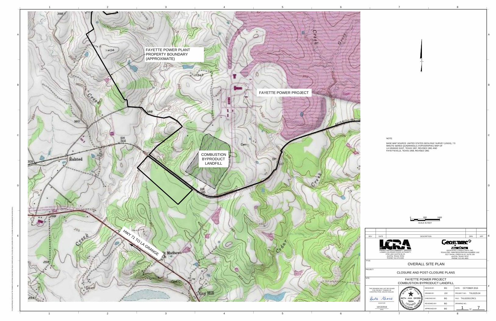
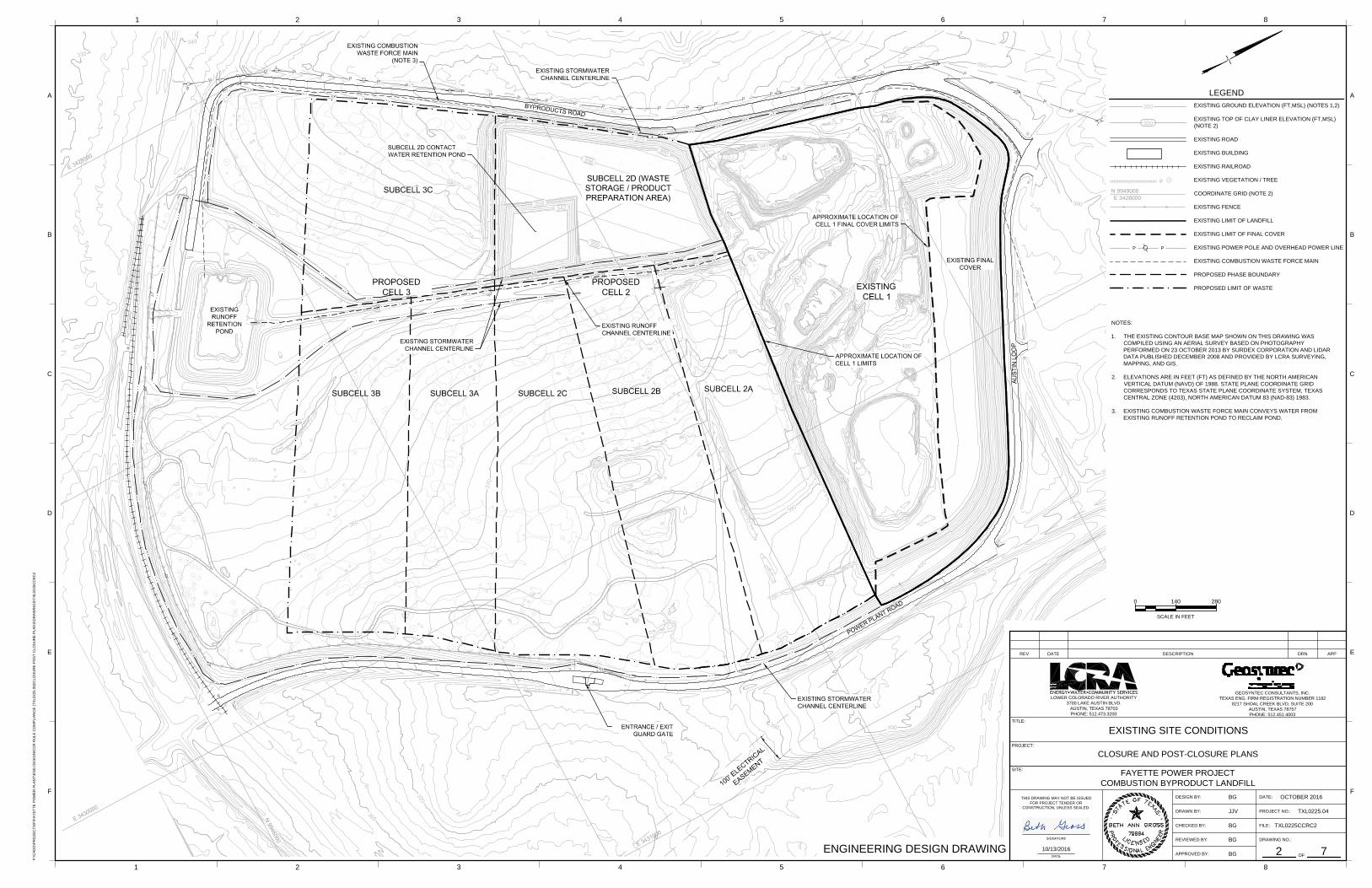
The FPP is a coal-fired power plant located east of La Grange in Fayette County, Texas. CCR generated at the facility are disposed in the CBL, a CCR landfill located south of the power plant and north of the railroad that borders the FPP site (Drawing 1). At final buildout, the CBL will consist of up to three cells, Cells 1 to 3 (Drawing 2). Depending on the rates of CCR production and beneficial use, all cells may not be needed for CCR disposal and the final CBL footprint would be smaller (e.g., Cells 1 and 2, Drawing 3).
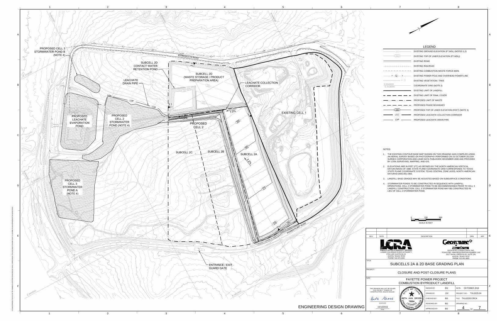
Cell 1 was constructed in 1988 with a recompacted clay liner installed over natural clay subgrade. This liner is equivalent to the liner recommended at that time in Texas Water Commission (TWC) Guideline No. 3 for Class 2 industrial waste landfills: a 2-foot thick (minimum) recompacted clay-rich liner or 3 feet of in-place soil exhibiting a permeability less than 1 × 10⁻⁷ cm/s (TWC, 1988). The northern slope of Cell 1 was closed with a final cover system in 1992 (Drawing 2). From October 2014 to May 2015, Subcell 2D was constructed with a 3-foot thick compacted clay liner with a hydraulic conductivity less than 1 × 10⁻⁷ cm/s, which meets the recommendations of Texas Commission on Environmental Quality (TCEQ) Technical Guideline No. 3 (2015) for Class 2 monofills of consistent, well characterized waste. This subcell currently includes a contact water retention pond lined with a geomembrane/compacted clay composite liner (Drawing 2). Subcell 2D is being used as a waste storage/product preparation area during CCR operations in Cell 1 and future Subcells 2A, 2B and 2C. Cell 1 and Subcell 2D are existing CCR landfill areas under 40 CFR §257.53. The remainder of Cells 2 and 3 will be constructed with a liner system that meets the requirements of 40 CFR §257.70(b) and (d), which includes a leachate collection system and underlying geomembrane/compacted clay composite liner.
Runoff from active areas in Cell 1 of the CBL currently drains to the Runoff Retention Pond via the runoff channel (Drawing 2). Contact water from the Subcell 2D Contact Water Retention Pond can also drain to the Runoff Retention Pond by pumping it to the runoff channel. The Runoff Retention Pond is permitted under LCRA’s Texas Pollutant Discharge Elimination System (TPDES) Permit No. WQ0002105000 and is designated as the CBL Pond in the permit. The permit allows water in the pond to be managed by conveying it to the FPP Reclaim Pond or,
LCRA Fayette Power Project Closure and Post-Closure Plans
TXL0225/Closure and Post-Closure Plan_Oct 2016.docx 2 Geosyntec Consultants
October 2016
if effluent limitations are met, by discharging via Outfall 004. The Runoff Retention Pond will be used for management of contact water and leachate from the active area until the Leachate Evaporation Pond (Drawing 4) is constructed, which will occur prior to disposal of CCR in Subcell 2A (Drawing 4). Stormwater run-off from the final cover system of the CBL flows in drainage channels along the perimeter of the CBL that primarily discharge south of the CBL but also discharge to a drainage ditch north of the CBL. When CCR disposal operations are initiated in Cell 2, the majority of stormwater run-off from the final cover system will flow into a stormwater pond prior to being discharged from the site (Drawing 4).
1.3 Organization of Plan
The remainder of this Plan is organized as follows:
• Section 2 presents a narrative description of the CBL closure process, including estimates of the maximum inventory of CCR in the CBL that could ever be on site and the largest area of the CBL that would require final cover system at any time during the active life of the CBL (40 CFR §257.102(b)(1)(iv) and (v));
• Section 3 describes the design and installation procedures for a final cover system for the CBL that meets the closure performance standard (40 CFR §257.102(b)(1)(iii) and (d));
• Section 4 presents a schedule for completing closure activities (40 CFR §257.102(b)(1)(vi));
• Section 5 presents a narrative description of the CBL post-closure process (40 CFR §257.104(d);
• Section 6 presents a certification by a qualified professional engineer that this Closure and Post-Closure Plan meets the requirements of 40 CFR §257.102(b); and
• Section 7 provides a list of references cited in the Plan.
LCRA Fayette Power Project Closure and Post-Closure Plans
TXL0225/Closure and Post-Closure Plan_Oct 2016.docx 3 Geosyntec Consultants
October 2016
2. CBL CLOSURE
2.1 Overview
The CBL will be closed in accordance with recognized and generally accepted good engineering practices as described in this Closure Plan. Closure of the CBL will be accomplished by leaving CCR in place and constructing a final cover system over the CCR. Closure of the CBL also includes installing associated stormwater management features and establishing vegetation on the final cover. When no longer needed for management of CCR, contact water, and leachate, facility equipment will be cleaned and decontaminated and ancillary components will be removed. 2.2 Largest Area Requiring Final Cover
The largest area of the CBL that would ever require a final cover during the active life of the CBL is approximately 22 acres. This area represents the CBL as it currently exists (Drawing 2). It is anticipated that the CBL will undergo partial closure, in 10 to 15 acre increments, as additional cells are constructed through a phased installation of final cover system as sections of the landfill are brought to their final design top of waste grades. Therefore, the current scenario of a 22-acre active area is a temporary condition that is not expected to exist after Subcell 2A is constructed.
2.3 Maximum Waste Inventory
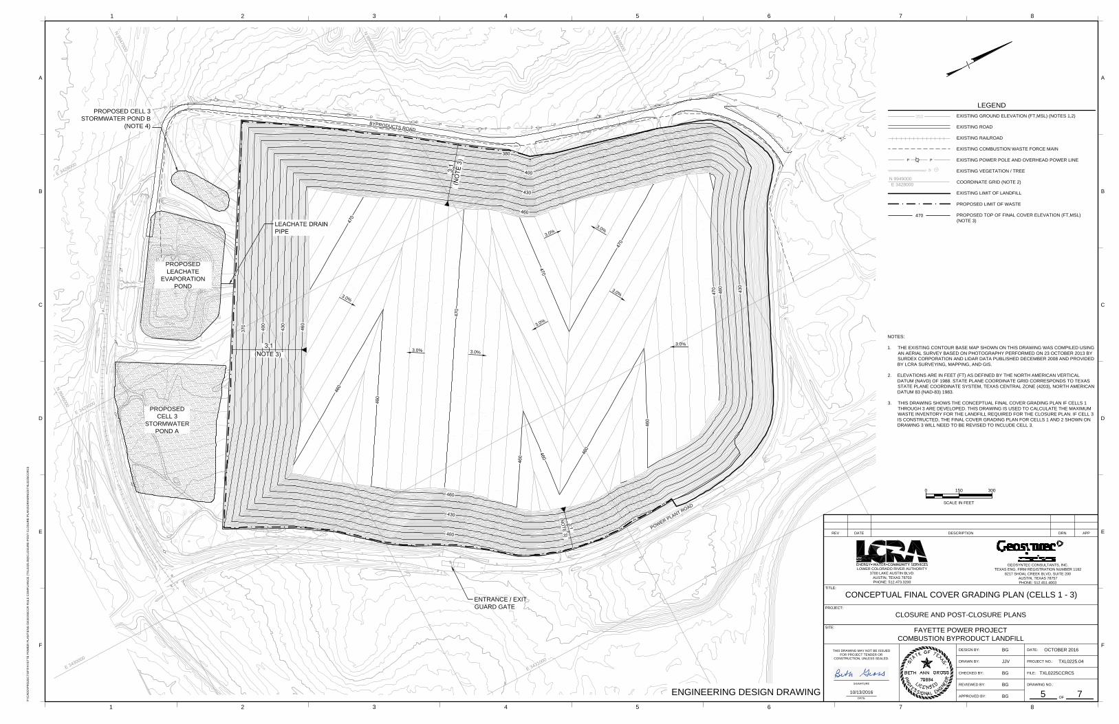
The CBL is designed to be developed with two cells (Drawing 3) or three cells (Drawing 5), depending on the total CCR disposal capacity required. The maximum inventory of CCR in the CBL will occur if three cells are developed and filled. For this scenario (Drawing 5), the calculated maximum waste inventory in the CBL is approximately 12,400,000 cubic yards. If the CBL is closed prematurely as Cell 1 only, the maximum inventory of CCR requiring a final cover in the 22-acre active area of the cell is approximately 2,400,000 cubic yards. 2.4 Closure Activities
The closure activities for the CBL, organized in general accordance with the sequence in which they will occur during a closure event, are summarized below.
• Notification of Intent to Close. In accordance with 40 CFR §257.102(g), no later than the date of closure initiation, a notice of intent to close the CBL or portion thereof will be prepared and placed in the facility’s Operating Record. The notification will include a certification by a qualified professional engineer that the design of the final cover system meets the requirements of 40 CFR §257.102(d)(3).
• Construct Final Cover System and Install Stormwater Management Features. After the final cover system subgrade has been graded and surveyed, the final cover system
LCRA Fayette Power Project Closure and Post-Closure Plans
TXL0225/Closure and Post-Closure Plan_Oct 2016.docx 4 Geosyntec Consultants
October 2016
components will be constructed and the stormwater management features will be installed. The design and installation of the final cover system is described in Section 3 of this Closure Plan.
• Equipment Cleaning and Decontamination. During final facility closure, facility equipment that contacted waste during active operations or closure activities will be cleaned prior to moving the equipment from the facility or placing it into service for post-closure activities.
2.5 Certification of Closure Completion
In accordance with 40 CFR §257.102(f)(3), upon completion of closure of the CBL or portion thereof, a certification from a qualified professional engineer must be obtained to confirm that closure has been completed in accordance with the Closure Plan and the requirements of 40 CFR §257.102(d). Note that this certification is not required for the approximately 7.9 acres of final cover previously constructed over the north end of Cell 1 as that area was closed in 1992, more than two decades before the effective date of 40 CFR §257.102(f)(3),
In accordance with 40 CFR §257.102(h), within 30 days of completion of closure of the CBL or portion thereof, a notification of closure will be prepared and placed in the facility’s Operating Record. The notification will include the professional engineer certification of closure.
2.6 Deed Notation
In accordance with 40 CFR §257.102(i), following closure of the CBL, a notation will be recorded on the facility deed indicating that: (i) the property has been used for CCR disposal; and (ii) the use of the property is restricted under the post-closure care requirements as provided by 40 CFR §257.104(d)(1)(iii).
In accordance with 40 CFR §257.102(i)(3), within 30 days of recording the deed notation, a notification stating that the notation has been recorded in the Fayette County Deed Records will be placed in the facility’s Operating Record.
2.7 Amendment of Closure Plan
In accordance with 40 CFR §257.102(b)(3), this Closure Plan may be amended at any time. Any amendment of the Closure Plan requires a written certification by a qualified professional engineer that the amendment meets the requirements of 40 CFR §257.102(b).
When conditions occur that necessitate a change to the Closure Plan, it must be amended within the following timeframes:
• at least 60 days prior to changing the operation of the CBL in a manner that would substantially affect the activities described in this Closure Plan;
LCRA Fayette Power Project Closure and Post-Closure Plans
TXL0225/Closure and Post-Closure Plan_Oct 2016.docx 5 Geosyntec Consultants
October 2016
• within 60 days after an unanticipated event requires the need to revise the activities described in this Closure Plan, if closure activities have not yet been initiated for the CBL; and
• within 30 days after an unanticipated event requires the need to revise the activities described in this Closure Plan, if closure activities are underway.
LCRA Fayette Power Project Closure and Post-Closure Plans
TXL0225/Closure and Post-Closure Plan_Oct 2016.docx 6 Geosyntec Consultants
October 2016
3. FINAL COVER SYSTEM
3.1 Closure Performance Standard
The CBL will be closed in a manner that meets the performance standard of 40 CFR §257.102(d). As such, it will be closed with a final cover system designed to isolate CCR from surface water and the atmosphere, promote good surface drainage, minimize erosion, minimize water infiltration into the underlying CCR and thus leachate generation and potential release, provide for slope stability, and minimize the need for further maintenance. 3.2 Final Cover Grades
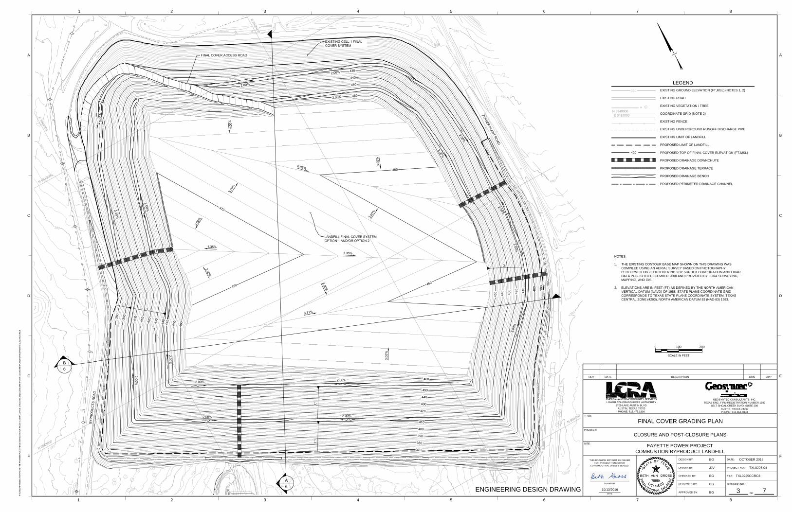
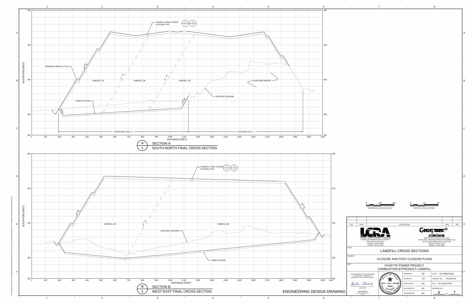
Consistent with the closure performance standard of 40 CFR §257.102(d), the final cover system of the CBL will be graded to promote runoff and minimize erosion. The final grades (top of final cover system) for the CBL are shown on Drawings 3 for the scenario with Cells 1 and 2 constructed. The final cover system will have a maximum elevation of approximately 470 feet above mean sea level, minimum top deck slope of 3%, and maximum side slope of 3 horizontal: 1 vertical (Drawings 3). The side slopes will include 12-foot (minimum) wide drainage benches orientated approximately parallel to the slopes with a maximum vertical spacing of 63 feet. The maximum spacing of the drainage benches was selected to limit calculated annual soil loss to 3 tons/acre/year consistent with TCEQ guidance (TCEQ, 2007). The CBL perimeter will include a perimeter berm consisting of compacted soil with exterior side slopes of 3 horizontal: 1 vertical. Landfill cross sections showing the overall CBL configuration for the scenario with Cells 1 and 2 constructed are presented on Drawing 6. 3.3 Stormwater Management
For the scenario with Cells 1 and 2 constructed, the stormwater management system for the CBL is designed to divert surface water run-on from a 100-year, 24-hour storm event (rainfall depth of 10.5 inches) as recommended by TCEQ (2015). It is also designed to control runoff from that design storm. Designing the stormwater management system on the final cover system to accommodate runoff from a 100-year, 24-hour storm event reduces the potential for overtopping of the stormwater features during intense precipitation events and, hence, meets the final cover system performance goal of minimizing the need for further final cover maintenance. The stormwater management features will include drainage benches orientated approximately parallel to the final cover system side slopes and drainage downchutes that intersect the drainage benches and convey runoff to a perimeter drainage channel and then to one or two Stormwater Ponds (Drawings 3 and 4). 3.4 Final Cover System Configuration
In accordance with 40 CFR § 257.102 (d)(3)(i), the final cover system must consist of at least two components: (i) a low-permeability infiltration layer (i.e., barrier layer) that minimizes
LCRA Fayette Power Project Closure and Post-Closure Plans
TXL0225/Closure and Post-Closure Plan_Oct 2016.docx 7 Geosyntec Consultants
October 2016
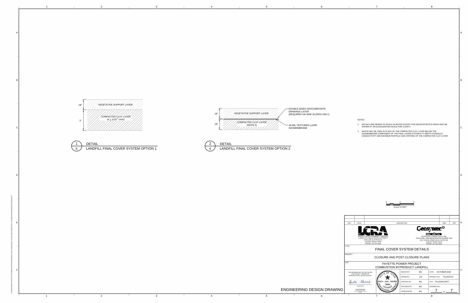
infiltration of liquids into the closed CCR unit, and (ii) an overlying erosion layer (i.e., vegetative support layer) that is capable of sustaining native plant growth. The permeability of the infiltration layer for a final cover system must be less than or equal to the permeability of the liner or no greater that 1 × 10⁻⁵ cm/sec, whichever is less, and the thickness of this layer must be at least 18 inches (40 CFR § 257.102 (d)(3)(i)(A) and (B)). The thickness of the erosion layer must be at least 6 inches (40 CFR § 257.102 (d)(3)(i)(C)). The final cover system recommended in TCEQ Technical Guideline No. 3 (2015) for Class 2 monofills of consistent, well characterized waste consists of a 3-foot thick compacted clay layer with a hydraulic conductivity no greater that 1 × 10⁻⁷ cm/sec and an overlying 18-inch thick uncompacted topsoil layer. Further, TCEQ recommends a drainage layer beneath the topsoil to reduce infiltration through the cover and increase slope stability. In 1992, an approximately 7.9 acre area on the north side of Cell 1 was closed with a final cover system consisting of a 2-foot thick compacted clay layer (with hydraulic conductivity no greater than 1 × 10⁻⁷ centimeter/second [cm/s]) overlain by 1 foot of general fill and at least 1 foot of topsoil. In the March 2013 Revision to Notification for the Combustion Byproduct Landfill (Geosyntec, 2013), two final cover system designs generally consistent with the recommendations of TCEQ (2015) were identified for final closure. These closure designs have been modified, where necessary, to meet the requirements of 40 CFR §257.102(d)(3)(i). Either of these options may be implemented as the CBL is incrementally closed. The Option 1 final cover system meets both the requirements of 40 CFR § 257.102 (d)(3)(i) and the recommendations of TCEQ (2015) and consists of, from top to bottom:
• 18-inch thick vegetative support layer (erosion layer); and
• 3-foot thick compacted clay layer (infiltration layer) with a hydraulic conductivity no greater 1 × 10⁻⁷ cm/s.
The slope stability calculations presented subsequently in Section 3.6 demonstrate that an internal drainage layer is not needed to provide slope stability of the Option 1 final cover system. Further the existing final cover system constructed on the north side of Cell 1 has performed well, without evidence of slope instability, over the 24 years since it was constructed.
The Option 2 final cover system meets the requirements of 40 CFR § 257.102 (d)(3)(i) and the recommended erosion layer thickness of TCEQ (2015) and consists of the following components, from top to bottom (40 CFR §257.102(d)(3)(i)):
• 18-inch thick vegetative support layer (erosion layer);
• double-sided geocomposite drainage layer (required on side slopes only); and
LCRA Fayette Power Project Closure and Post-Closure Plans
TXL0225/Closure and Post-Closure Plan_Oct 2016.docx 8 Geosyntec Consultants
October 2016
composite cap (infiltration layer) with a 40-mil thick textured linear low density polyethylene (LLDPE) geomembrane upper component and an 18-inch thick compacted clay lower component with a hydraulic conductivity no greater 1 × 10⁻⁵ cm/s; CCR may be used to construct the barrier below the geomembrane component for the final cover system if such barrier meets the hydraulic conductivity and maximum particle size criteria of the compacted clay layer.
3.5 Design and Installation of Final Cover System Components
3.5.1 Infiltration Layer
The final cover system infiltration layer will be a composite cap or a compacted clay layer. The infiltration layer is designed with a low hydraulic conductivity to minimize water infiltration into the underlying CCR.
• Compacted Clay. The compacted clay component of the final cover system will meet the following material specifications:
o maximum particle size of 2 in.;
o no more than 10% retained on the No. 4 sieve;
o no less than 30% passing the No. 200 sieve;
o minimum liquid limit of 30;
o minimum plasticity index of 15; and
o maximum hydraulic conductivity of 1 × 10⁻⁵ cm/s when the compacted clay layer is a component of a composite infiltration layer and 1 × 10⁻⁷ cm/s when the compacted clay layer is the infiltration layer.
The compacted clay will be placed in 9-inch thick (maximum) loose lifts to allow adequate compaction to be achieved throughout the overall layer thickness. The clay will be compacted to at least 95% of its Standard Proctor maximum dry density at a moisture content from 0 to 4 percentage points wet of the optimum to form a low hydraulic conductivity layer. Prior to installation of an overlying geomembrane, the surface of the compacted clay layer will be inspected and verified to be smooth and few of particles greater than ½ inch in diameter, sticks, roots, sharp objects, and other deleterious objects that could damage the geomembrane.
• Geomembrane. The textured LLDPE geomembrane will be placed in direct contact with the underlying compacted clay layer so that a compression seal (composite barrier) forms
LCRA Fayette Power Project Closure and Post-Closure Plans
TXL0225/Closure and Post-Closure Plan_Oct 2016.docx 9 Geosyntec Consultants
October 2016
between the two layers from the overburden load. After geomembrane panels are deployed, they will be welded together to create a continuous sheet.
3.5.2 Geocomposite Drainage Layer
A geocomposite drainage layer will be installed between the erosion layer and the infiltration layer on landfill side slopes when a composite infiltration layer is used. The purpose of the geocomposite drainage layer is to reduce the head of water on the infiltration layer, thereby reducing the potential for leakage into the infiltration layer and enhancing the slope stability of the final cover system side slopes. The geocomposite will consist of a high density polyethylene (HDPE) geonet with a nonwoven geotextile bonded to its top and bottom surfaces (i.e., double-sided geocomposite). Water collected in the drainage layer will be conveyed to the edges of the final cover system where it will exit into the stormwater management system.
3.5.3 Erosion Layer
The final cover system erosion layer will be a vegetative support layer. The vegetative support layer will be placed on top of the geocomposite drainage layer, vegetated, and maintained to prevent erosion.
3.6 Final Cover Slope Stability
An infinite slope stability analysis was conducted for the two final cover system options. Based on TCEQ (2015), the target factor of safety is 1.3 using peak strength and 1.0 using residual strength. For Option 1, the critical interface is between the vegetative support layer (saturated) and the underlying compacted clay layer. For Option 2, the critical interface for slope stability is between the geomembrane and the underlying compacted clay layer. The factor of safety for stability of an infinite slope that may include a saturated zone that acts on a critical interface can be calculated using a simplified version of the Giroud et al. (1995) equation: = − + ⁄
where: γsat = saturated soil unit weight; γw = water unit weight = 0 if there is not a hydraulic head in the soil layer; φ = geosynthetic interface friction angle or soil internal friction angle; β = slope angle; c = geosynthetic interface adhesion (assumed to be 0) or soil cohesion; and t = soil thickness.
The input parameters used to evaluate the slope stability of the two final cover options on the CBL side slopes were selected based on published interface shear strengths, data from Geosyntec’s project database, and the final cover side slope inclination. For Option 1, the following input parameters were selected: γsat = 105 pcf, γw = 62.4 pcf; φ = 28° (peak) and 20° (residual); β = 18.4°; c = 50 psf; and t = 1.5 ft. With these parameters, the calculated FSs are 1.65 (peak) and 1.45 (residual), respectively. The following input parameters were selected for Option
LCRA Fayette Power Project Closure and Post-Closure Plans
TXL0225/Closure and Post-Closure Plan_Oct 2016.docx 10 Geosyntec Consultants
October 2016
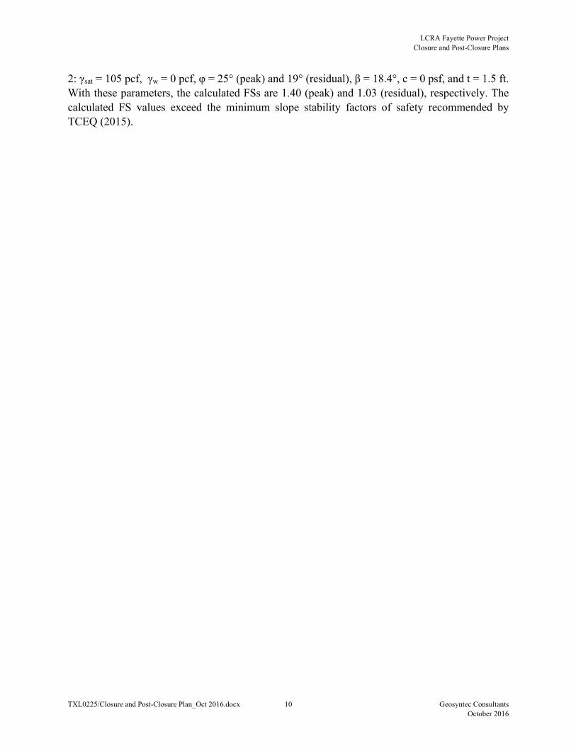
2: γsat = 105 pcf, γw = 0 pcf, φ = 25° (peak) and 19° (residual), β = 18.4°, c = 0 psf, and t = 1.5 ft. With these parameters, the calculated FSs are 1.40 (peak) and 1.03 (residual), respectively. The calculated FS values exceed the minimum slope stability factors of safety recommended by TCEQ (2015).
LCRA Fayette Power Project Closure and Post-Closure Plans
TXL0225/Closure and Post-Closure Plan_Oct 2016.docx 11 Geosyntec Consultants
October 2016
4. CLOSURE SCHEDULE
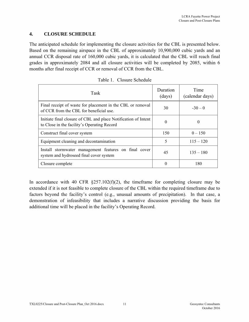
The anticipated schedule for implementing the closure activities for the CBL is presented below. Based on the remaining airspace in the CBL of approximately 10,900,000 cubic yards and an annual CCR disposal rate of 160,000 cubic yards, it is calculated that the CBL will reach final grades in approximately 2084 and all closure activities will be completed by 2085, within 6 months after final receipt of CCR or removal of CCR from the CBL.
Table 1. Closure Schedule
Task Duration
(days) Time
(calendar days)
Final receipt of waste for placement in the CBL or removal of CCR from the CBL for beneficial use.
30 -30 – 0
Initiate final closure of CBL and place Notification of Intent to Close in the facility’s Operating Record
0 0
Construct final cover system 150 0 – 150
Equipment cleaning and decontamination 5 115 – 120
Install stormwater management features on final cover system and hydroseed final cover system
45 135 – 180
Closure complete 0 180
In accordance with 40 CFR §257.102(f)(2), the timeframe for completing closure may be extended if it is not feasible to complete closure of the CBL within the required timeframe due to factors beyond the facility’s control (e.g., unusual amounts of precipitation). In that case, a demonstration of infeasibility that includes a narrative discussion providing the basis for additional time will be placed in the facility’s Operating Record.
LCRA Fayette Power Project Closure and Post-Closure Plans
TXL0225/Closure and Post-Closure Plan_Oct 2016.docx 12 Geosyntec Consultants
October 2016
5. CBL POST-CLOSURE
5.1 Introduction
After the CBL is closed, the facility will enter a 30-year post-closure care period. This section presents the Post-Closure Plan for the facility, which describes how the CBL will be maintained and monitored during the post-closure care period.
5.2 Facility Contact
During the post-closure care period, the primary contact for the CBL will be:
Ms. Nancy Overesch, P.G., CPEA LCRA Environmental Compliance and Permitting P.O. Box 220, MS H322 Austin, Texas 78767 Phone: (512) 578-2939 Email: [email protected]
5.3 Post-Closure Overview
The post-closure activities for the CBL will comply with requirements of 40 CFR §257.104 and will begin after closure is completed. Facility activities conducted during the post-closure care period will include:
• maintaining the integrity and effectiveness of the final cover system, including making repairs to the final cover as necessary to correct the effects of settlement, subsidence, erosion, or other events;
• preventing run-on and run-off from eroding or otherwise damaging the landfill final cover;
• maintaining the integrity and effectiveness of the leachate collection system; and
• maintaining the groundwater monitoring system and monitoring groundwater.
5.4 Post-Closure Maintenance Activities
During the post-closure care period, the facility will conduct regularly scheduled inspections of the CBL (Section 5.5) and will perform maintenance as needed to mitigate potential performance issues identified during the inspections. The facility will also continue to conduct groundwater monitoring. Additional details of the maintenance activities are provided below.
• Final Cover System. The upper portion of the final cover system consists of a vegetative support layer, which is overlain in some locations by stormwater management features. A
LCRA Fayette Power Project Closure and Post-Closure Plans
TXL0225/Closure and Post-Closure Plan_Oct 2016.docx 13 Geosyntec Consultants
October 2016
vegetative cover will be established on the final cover system and maintained to reduce the potential for final cover system erosion. The vegetative cover will be mowed at least once a year to help maintain healthy vegetation, prevent brush and trees from being established, and allow for visual inspection of the final cover system. Areas of missing or deficient vegetation will be re-seeded. Erosion gullies in the vegetative support layer or areas that have standing water due to settlement or subsidence will be repaired by in-filling the gullies or depressions and re-seeding. If erosion or other final cover damage (e.g., burrowing animals) extends through the vegetative support layer, the affected area of the final cover system will be repaired to the same design specifications as the original cover. Stormwater management features on the final cover system or at the CBL perimeter will be maintained as needed (e.g., remove sediment, vegetation, or other obstructions to restore the dimensions and surface of stormwater conveyances).
• Perimeter Berm. The vegetative cover on the perimeter berm will be mowed at least once a year to help maintain healthy vegetation, prevent brush and trees from being established, and allow for visual inspection. Areas of missing or deficient vegetation will be re-seeded. Erosion gullies will be repaired by in-filling the gullies and re-seeding.
• Leachate Collection System. The leachate collection system will be operated during the post-closure period until landfills stops generating leachate. Maintenance will consist of replacing features that are deteriorated or that will not function as intended, as identified during the routine inspections.
• Runoff Retention Pond or Leachate Evaporation Pond. The pond in place at the time of closure will remain in operation during the post-closure care period to receive leachate collected from the CBL. Maintenance will consist of replacing features that are deteriorated or that will not function as intended, as identified during the routine inspections.
• Groundwater Monitoring System. Groundwater monitoring (and associated sampling, analysis, and reporting) will be performed during the post-closure care period. Groundwater monitoring wells will be maintained by keeping the wells unobscured by vegetation and repairing/replacing monitoring well features (casing, bollards, locks, etc.) that are deteriorated or that will not function as intended, as identified during inspections during the monitoring events. Other possible maintenance may include well redevelopment or replacement, as needed.
5.5 Post-Closure Inspection Requirements and Frequencies
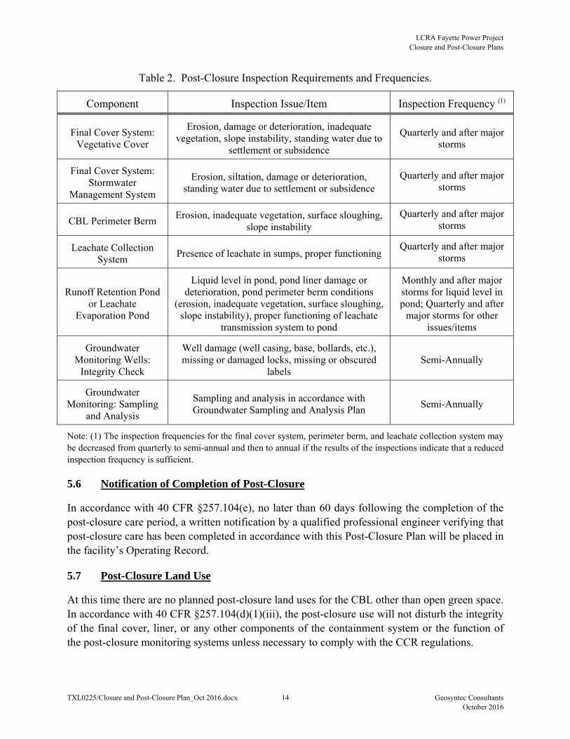
The post-closure care inspection requirements and frequencies are presented in Table 2.
LCRA Fayette Power Project Closure and Post-Closure Plans
TXL0225/Closure and Post-Closure Plan_Oct 2016.docx 14 Geosyntec Consultants
October 2016
Table 2. Post-Closure Inspection Requirements and Frequencies.
Component Inspection Issue/Item Inspection Frequency (1)
Final Cover System: Vegetative Cover
Erosion, damage or deterioration, inadequate vegetation, slope instability, standing water due to
settlement or subsidence
Quarterly and after major storms
Final Cover System: Stormwater
Management System
Erosion, siltation, damage or deterioration, standing water due to settlement or subsidence
Quarterly and after major storms
CBL Perimeter Berm Erosion, inadequate vegetation, surface sloughing,
slope instability Quarterly and after major
storms
Leachate Collection System
Presence of leachate in sumps, proper functioning Quarterly and after major
storms
Runoff Retention Pond or Leachate
Evaporation Pond
Liquid level in pond, pond liner damage or deterioration, pond perimeter berm conditions
(erosion, inadequate vegetation, surface sloughing, slope instability), proper functioning of leachate
transmission system to pond
Monthly and after major storms for liquid level in pond; Quarterly and after
major storms for other issues/items
Groundwater Monitoring Wells:
Integrity Check
Well damage (well casing, base, bollards, etc.), missing or damaged locks, missing or obscured
labels Semi-Annually
Groundwater Monitoring: Sampling
and Analysis
Sampling and analysis in accordance with Groundwater Sampling and Analysis Plan
Semi-Annually
Note: (1) The inspection frequencies for the final cover system, perimeter berm, and leachate collection system may be decreased from quarterly to semi-annual and then to annual if the results of the inspections indicate that a reduced inspection frequency is sufficient.
5.6 Notification of Completion of Post-Closure
In accordance with 40 CFR §257.104(e), no later than 60 days following the completion of the post-closure care period, a written notification by a qualified professional engineer verifying that post-closure care has been completed in accordance with this Post-Closure Plan will be placed in the facility’s Operating Record.
5.7 Post-Closure Land Use
At this time there are no planned post-closure land uses for the CBL other than open green space. In accordance with 40 CFR §257.104(d)(1)(iii), the post-closure use will not disturb the integrity of the final cover, liner, or any other components of the containment system or the function of the post-closure monitoring systems unless necessary to comply with the CCR regulations.
LCRA Fayette Power Project Closure and Post-Closure Plans
TXL0225/Closure and Post-Closure Plan_Oct 2016.docx 15 Geosyntec Consultants
October 2016
5.8 Amendment of Post-Closure Plan
In accordance with CFR §257.104(d)(3), this Post-Closure Plan may be amended at any time. Any amendment of the Post-Closure Plan requires a written certification by a qualified professional engineer that the amendment meets the requirements of CFR §257.104(d).
When conditions occur that necessitate a change to the Post-Closure Plan, it must be amended within the following timeframes:
• at least 60 days prior to changing the operation of the CBL in a manner that would substantially affect the activities described in this Post-Closure Plan;
• within 60 days after an unanticipated event requires the need to revise the activities described in this Post-Closure Plan, if post-closure activities have not yet been initiated for the CBL; and
• within 30 days after an unanticipated event requires the need to revise the activities described in this Post-Closure Plan, if post-closure activities are underway.
LCRA Fayette Power Project Closure and Post-Closure Plans
TXL0225/Closure and Post-Closure Plan_Oct 2016.docx 16 Geosyntec Consultants
October 2016
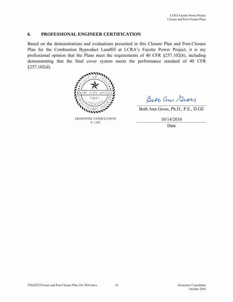
6. PROFESSIONAL ENGINEER CERTIFICATION
Based on the demonstrations and evaluations presented in this Closure Plan and Post-Closure Plan for the Combustion Byproduct Landfill at LCRA’s Fayette Power Project, it is my professional opinion that the Plans meet the requirements of 40 CFR §257.102(b), including demonstrating that the final cover system meets the performance standard of 40 CFR §257.102(d).
Beth Ann Gross, Ph.D., P.E., D.GE
10/14/2016
Date
GEOSYNTEC CONSULTANTS F- 1182
LCRA Fayette Power Project Closure and Post-Closure Plans
TXL0225/Closure and Post-Closure Plan_Oct 2016.docx 17 Geosyntec Consultants
October 2016
7. REFERENCES
Geosyntec Consultants (2013). “Revision to Notification for the Combustion Byproduct Landfill, Registration No. 31575, LCRA Fayette Power Project, Fayette County, Texas,” prepared for LCRA, March.
Giroud, J.P., Bachus, R.C., and Bonaparte, R. (1995). “Influence of Water Flow on the Stability of Geosynthetic-Soil Layered Systems on Slopes,” Geosynthetics International, Vol. 2, No. 6, pp. 1149-1180.
Texas Commission on Environmental Quality ( 2015). “Nonhazardous Industrial Solid Waste Landfills,” Industrial Solid Waste Management, Draft Technical Guideline No. 3.
Texas Commission on Environmental Quality (2007). “Guidance for Addressing Erosional Stability During All Phases of Landfill Operation (Draft),” 14 February.
Texas Water Commission (1988). Letter from Minor Brooks Hibbs, Permits Section Chief, Hazardous and Solid Waste Division of TWC to Tom Remaley, Director of Environmental Quality, LCRA, indicating that the design of Cell 1 substantially conforms to the TWC Industrial Solid Waste Technical Guidelines, Jan 18.

LCRA Fayette Power Project Closure and Post-Closure Plan
TXL0225/Closure and Post-Closure Plan_Oct 2016.docx Geosyntec Consultants
October 2016
DRAWINGS
FAYETTE POWER PROJECT
H
W
Y
7
1
T
O
L
A
G
R
A
N
G
E
COMBUSTION
BYPRODUCT
LANDFILL
FAYETTE POWER PLANT
PROPERTY BOUNDARY
(APPROXIMATE)
P:\C
AD
D\P
RO
JE
CT
S\F
\F
AY
ET
TE
P
OW
ER
P
LA
NT
\E
NG
D
ES
IG
N\C
CR
R
UL
E C
OM
PL
IA
NC
E (T
XL
02
25
.0
8)\C
LO
SU
RE
-P
OS
T C
LO
SU
RE
P
LA
NS
\D
RA
WIN
GS
\T
XL
02
25
CC
RC
1
BG
JJV
BG
BG
BG
1
TXL0225CCRC1
1 2 3 54 6 7 8
ENGINEERING DESIGN DRAWING
CLOSURE AND POST-CLOSURE PLANS
FAYETTE POWER PROJECT
COMBUSTION BYPRODUCT LANDFILL
PROJECT:
SITE:
TITLE:
APPROVED BY:
REVIEWED BY: DRAWING NO.:
OF
DRAWN BY:
DESIGN BY:
CHECKED BY: FILE:
PROJECT NO.:
DATE:
DATEREV APPDESCRIPTION DRN
OCTOBER 2016
TXL0225.04
7
F
E
D
C
B
A
1 2 3 54 6 7 8
F
E
D
C
B
A
GEOSYNTEC CONSULTANTS, INC.
TEXAS ENG. FIRM REGISTRATION NUMBER 1182
8217 SHOAL CREEK BLVD, SUITE 200
AUSTIN, TEXAS 78757
PHONE: 512.451.4003
10/2016A ABISSUE FOR BID JJV / KH
3/13/20150 MZIISSUE FOR CONSTRUCTION JJV / KH
LOWER COLORADO RIVER AUTHORITY
3700 LAKE AUSTIN BLVD.
AUSTIN, TEXAS 78703
PHONE: 512.473.3200
COMMUNITY SERVICESENERGYWATER
THIS DRAWING MAY NOT BE ISSUED
FOR PROJECT TENDER OR
CONSTRUCTION, UNLESS SEALED.
SIGNATURE
DATE
10/13/2016
OVERALL SITE PLAN
NOTE:
BASE MAP SOURCE: UNITED STATES GEOLOGIC SURVEY (USGS), 7.5
MINUTE SERIES QUADRANGLE (TOPOGRAPHIC) MAP OF
LA GRANGE EAST, TEXAS 1957, REVISED 1981 AND
FAYETTEVILLE, TEXAS 1958, REVISED 1981
0
SCALE IN FEET
800 1600
N
E
3
4
2
8
0
0
0
E
3
4
3
0
0
0
0
E
3
4
3
1
0
0
0
N
9
9
4
6
0
0
0
EXISTING
RUNOFF
RETENTION
POND
ENTRANCE / EXIT
GUARD GATE
B
Y
P
R
O
D
U
C
T
S
R
O
A
D
P
O
W
E
R
P
L
A
N
T
R
O
A
D
EXISTING FINAL
COVER
APPROXIMATE LOCATION OF
CELL 1 LIMITS
APPROXIMATE LOCATION OF
CELL 1 FINAL COVER LIMITS
EXISTING RUNOFF
CHANNEL CENTERLINE
EXISTING STORMWATER
CHANNEL CENTERLINE
EXISTING STORMWATER
CHANNEL CENTERLINE
EXISTING STORMWATER
CHANNEL CENTERLINE
EXISTING
CELL 1
EXISTING COMBUSTION
WASTE FORCE MAIN
(NOTE 3)
AU
ST
IN
LO
OP
3
6
0
3
7
0
3
8
0
3
9
0400
3
8
0
3
8
0
390
3
9
0
3
7
0
340
3
3
0
3
7
0
3
6
0
350
3
9
0
390
3
8
0
3
9
0
370
420
3
9
0
4
0
0
3
9
0
4
0
0
4
1
0
420
3
9
0
4
0
0
1
0
0
'
E
L
E
C
T
R
I
C
A
L
E
A
S
E
M
E
N
T
PROPOSED
CELL 2
SUBCELL 2A
SUBCELL 2B
SUBCELL 2C
SUBCELL 2D (WASTE
STORAGE / PRODUCT
PREPARATION AREA)
PROPOSED
CELL 3
SUBCELL 3ASUBCELL 3B
SUBCELL 3C
SUBCELL 2D CONTACT
WATER RETENTION POND
350
3
5
0
3
6
0
370
3
5
6
342
350
EXISTING GROUND ELEVATION (FT,MSL) (NOTES 1,2)
EXISTING TOP OF CLAY LINER ELEVATION (FT,MSL)
(NOTE 2)
EXISTING ROAD
EXISTING BUILDING
EXISTING RAILROAD
EXISTING VEGETATION / TREE
COORDINATE GRID (NOTE 2)
EXISTING FENCE
EXISTING LIMIT OF LANDFILL
EXISTING LIMIT OF FINAL COVER
EXISTING POWER POLE AND OVERHEAD POWER LINE
EXISTING COMBUSTION WASTE FORCE MAIN
PROPOSED PHASE BOUNDARY
PROPOSED LIMIT OF WASTE
LEGEND
E 3428000
N 9949000
N
NOTES:
1. THE EXISTING CONTOUR BASE MAP SHOWN ON THIS DRAWING WAS
COMPILED USING AN AERIAL SURVEY BASED ON PHOTOGRAPHY
PERFORMED ON 23 OCTOBER 2013 BY SURDEX CORPORATION AND LIDAR
DATA PUBLISHED DECEMBER 2008 AND PROVIDED BY LCRA SURVEYING,
MAPPING, AND GIS.
2. ELEVATIONS ARE IN FEET (FT) AS DEFINED BY THE NORTH AMERICAN
VERTICAL DATUM (NAVD) OF 1988. STATE PLANE COORDINATE GRID
CORRESPONDS TO TEXAS STATE PLANE COORDINATE SYSTEM, TEXAS
CENTRAL ZONE (4203), NORTH AMERICAN DATUM 83 (NAD-83) 1983.
3. EXISTING COMBUSTION WASTE FORCE MAIN CONVEYS WATER FROM
EXISTING RUNOFF RETENTION POND TO RECLAIM POND.
P P
P:\C
AD
D\P
RO
JE
CT
S\F
\F
AY
ET
TE
P
OW
ER
P
LA
NT
\E
NG
D
ES
IG
N\C
CR
R
UL
E C
OM
PL
IA
NC
E (T
XL
02
25
.0
8)\C
LO
SU
RE
-P
OS
T C
LO
SU
RE
P
LA
NS
\D
RA
WIN
GS
\T
XL
02
25
CC
RC
2
BG
JJV
BG
BG
BG
2
TXL0225CCRC2
1 2 3 54 6 7 8
ENGINEERING DESIGN DRAWING
CLOSURE AND POST-CLOSURE PLANS
FAYETTE POWER PROJECT
COMBUSTION BYPRODUCT LANDFILL
PROJECT:
SITE:
TITLE:
APPROVED BY:
REVIEWED BY: DRAWING NO.:
OF
DRAWN BY:
DESIGN BY:
CHECKED BY: FILE:
PROJECT NO.:
DATE:
DATEREV APPDESCRIPTION DRN
OCTOBER 2016
TXL0225.04
7
F
E
D
C
B
A
1 2 3 54 6 7 8
F
E
D
C
B
A
GEOSYNTEC CONSULTANTS, INC.
TEXAS ENG. FIRM REGISTRATION NUMBER 1182
8217 SHOAL CREEK BLVD, SUITE 200
AUSTIN, TEXAS 78757
PHONE: 512.451.4003
10/2016A ABISSUE FOR BID JJV / KH
3/13/20150 MZIISSUE FOR CONSTRUCTION JJV / KH
LOWER COLORADO RIVER AUTHORITY
3700 LAKE AUSTIN BLVD.
AUSTIN, TEXAS 78703
PHONE: 512.473.3200
COMMUNITY SERVICESENERGYWATER
THIS DRAWING MAY NOT BE ISSUED
FOR PROJECT TENDER OR
CONSTRUCTION, UNLESS SEALED.
SIGNATURE
DATE
10/13/2016
EXISTING SITE CONDITIONS
0
SCALE IN FEET
140 280
350
N
9
9
4
9
0
0
0
N
9
9
4
8
0
0
0
N
9
9
4
7
0
0
0
E
3
4
2
9
0
0
0
E
3
4
3
0
0
0
0
3.0
0%
0
.7
1
%
3:1
3:1
B
Y
P
R
O
D
U
C
TS
R
O
A
D
P
O
W
E
R
P
L
A
N
T
R
O
A
D
3:1
3
.
0
0
%
0
.8
5
%
3
.
0
0
%
3.00%
3
.
0
0
%
3
.
0
0
%
1.35%
3
:1
3:1
3.00%
2.00%
2.00%
2.00%
2.00%
2.00%
2.00%
3
.2
0
%
2
.
0
0
%
EXISTING CELL 1 FINAL
COVER SYSTEM
LANDFILL FINAL COVER SYSTEM
OPTION 1 AND/OR OPTION 2
2
.0
0
%
2
.0
0
%
3.20%
2.00%
2.00%
3
.
0
0
%
1.35%
2
.
0
0
%
2
.
0
0
%
2
.
0
0
%
2
.0
0
%
390
4
0
0
4
0
0
390
3
8
0
3
8
0
3
6
0
3
7
0
3
8
0
3
9
0
3
9
0
3
9
0
460
4
6
0
4
7
0
4
7
0
370
380
390
400
410
420
430
440
450
460
390
400
410
420
430
44
0
45
0
3
8
0
3
9
0
4
0
0
4
1
0
4
2
0
4
3
0
4
4
0
4
4
0
4
5
0
4
6
0
430
440
450
460
FINAL COVER ACCESS ROAD
A
6
B
6
350
EXISTING GROUND ELEVATION (FT,MSL) (NOTES 1, 2)
EXISTING ROAD
EXISTING VEGETATION / TREE
COORDINATE GRID (NOTE 2)
EXISTING FENCE
EXISTING UNDERGROUND RUNOFF DISCHARGE PIPE
EXISTING LIMIT OF LANDFILL
PROPOSED LIMIT OF LANDFILL
PROPOSED TOP OF FINAL COVER ELEVATION (FT,MSL)
PROPOSED DRAINAGE DOWNCHUTE
PROPOSED DRAINAGE TERRACE
PROPOSED DRAINAGE BENCH
PROPOSED PERIMETER DRAINAGE CHANNEL
LEGEND
E 3428000
N 9949000
N
420
P:\C
AD
D\P
RO
JE
CT
S\F
\F
AY
ET
TE
P
OW
ER
P
LA
NT
\E
NG
D
ES
IG
N\C
CR
R
UL
E C
OM
PL
IA
NC
E (T
XL
02
25
.0
8)\C
LO
SU
RE
-P
OS
T C
LO
SU
RE
P
LA
NS
\D
RA
WIN
GS
\T
XL
02
25
CC
RC
3
BG
JJV
BG
BG
BG
3
TXL0225CCRC3
1 2 3 54 6 7 8
ENGINEERING DESIGN DRAWING
CLOSURE AND POST-CLOSURE PLANS
FAYETTE POWER PROJECT
COMBUSTION BYPRODUCT LANDFILL
PROJECT:
SITE:
TITLE:
APPROVED BY:
REVIEWED BY: DRAWING NO.:
OF
DRAWN BY:
DESIGN BY:
CHECKED BY: FILE:
PROJECT NO.:
DATE:
DATEREV APPDESCRIPTION DRN
OCTOBER 2016
TXL0225.04
7
F
E
D
C
B
A
1 2 3 54 6 7 8
F
E
D
C
B
A
GEOSYNTEC CONSULTANTS, INC.
TEXAS ENG. FIRM REGISTRATION NUMBER 1182
8217 SHOAL CREEK BLVD, SUITE 200
AUSTIN, TEXAS 78757
PHONE: 512.451.4003
10/2016A ABISSUE FOR BID JJV / KH
3/13/20150 MZIISSUE FOR CONSTRUCTION JJV / KH
LOWER COLORADO RIVER AUTHORITY
3700 LAKE AUSTIN BLVD.
AUSTIN, TEXAS 78703
PHONE: 512.473.3200
COMMUNITY SERVICESENERGYWATER
THIS DRAWING MAY NOT BE ISSUED
FOR PROJECT TENDER OR
CONSTRUCTION, UNLESS SEALED.
SIGNATURE
DATE
10/13/2016
FINAL COVER GRADING PLAN
0 100 200
SCALE IN FEET
NOTES:
1. THE EXISTING CONTOUR BASE MAP SHOWN ON THIS DRAWING WAS
COMPILED USING AN AERIAL SURVEY BASED ON PHOTOGRAPHY
PERFORMED ON 23 OCTOBER 2013 BY SURDEX CORPORATION AND LIDAR
DATA PUBLISHED DECEMBER 2008 AND PROVIDED BY LCRA SURVEYING,
MAPPING, AND GIS.
2. ELEVATIONS ARE IN FEET (FT) AS DEFINED BY THE NORTH AMERICAN
VERTICAL DATUM (NAVD) OF 1988. STATE PLANE COORDINATE GRID
CORRESPONDS TO TEXAS STATE PLANE COORDINATE SYSTEM, TEXAS
CENTRAL ZONE (4203), NORTH AMERICAN DATUM 83 (NAD-83) 1983.
LC
C
LC
C
LC
C
EXISTING CELL 1
SUBCELL 2A
SUBCELL 2C
N
9
9
4
9
0
0
0
N
9
9
4
8
0
0
0
N
9
9
4
7
0
0
0
E
3
4
2
8
0
0
0
E
3
4
2
9
0
0
0
E
3
4
3
0
0
0
0
E
3
4
3
1
0
0
0
N
9
9
4
6
0
0
0
ENTRANCE / EXIT
GUARD GATE
B
Y
P
R
O
D
U
C
T
S
R
O
A
D
P
O
W
E
R
P
L
A
N
T
R
O
A
D
2
.
2
%
1.0%
1
.0
%
3
:1
3
:
1
3:1
3
:
1
LEACHATE COLLECTION
CORRIDOR
LEACHATE
DRAIN PIPE
PROPOSED
CELL 3
STORMWATER
POND A
(NOTE 4)
PROPOSED CELL 3
STORMWATER POND B
(NOTE 4)
SUBCELL 2B
L
D
P
L
D
P
L
D
P
PROPOSED
CELL 2
STORMWATER
POND (NOTE 4)
PROPOSED
LEACHATE
EVAPORATION
POND
SUBCELL 2D
CONTACT WATER
RETENTION POND
3
6
0
3
7
0
390
400
410
420
3
5
0
3
6
0
3
7
0
3
8
0
3
5
0
3
5
0
3
5
0
3
6
0
3
7
0
380
3
8
0
3
9
0
4
0
0
370
3
4
0
3
5
0
3
6
0
3
4
0
3
4
0
3
4
0
340
3
5
0
3
6
0
3
6
0
3
7
0
3
5
4
3
7
8
3
9
0
3
5
0
3
5
4
3
7
0
360
342
350
SUBCELL 2D
(WASTE STORAGE / PRODUCT
PREPARATION AREA)
PROPOSED
CELL 2
350
EXISTING GROUND ELEVATION (FT,MSL) (NOTES 1,2)
EXISTING TOP OF LINER ELEVATION (FT,MSL))
EXISTING ROAD
EXISTING RAILROAD
EXISTING COMBUSTION WASTE FORCE MAIN
EXISTING POWER POLE AND OVERHEAD POWER LINE
EXISTING VEGETATION / TREE
COORDINATE GRID (NOTE 2)
EXISTING LIMIT OF LANDFILL
EXISTING LIMIT OF FINAL COVER
PROPOSED LIMIT OF WASTE
PROPOSED PHASE BOUNDARY
PROPOSED TOP OF LINER ELEVATION (FEET) (NOTE 3)
PROPOSED LEACHATE COLLECTION CORRIDOR
PROPOSED LEACHATE DRAIN PIPE
LEGEND
E 3428000
N 9949000
N
NOTES:
1. THE EXISTING CONTOUR BASE MAP SHOWN ON THIS DRAWING WAS COMPILED USING
AN AERIAL SURVEY BASED ON PHOTOGRAPHY PERFORMED ON 23 OCTOBER 2013 BY
SURDEX CORPORATION AND LIDAR DATA PUBLISHED DECEMBER 2008 AND PROVIDED
BY LCRA SURVEYING, MAPPING, AND GIS.
2. ELEVATIONS ARE IN FEET (FT) AS DEFINED BY THE NORTH AMERICAN VERTICAL
DATUM (NAVD) OF 1988. STATE PLANE COORDINATE GRID CORRESPONDS TO TEXAS
STATE PLANE COORDINATE SYSTEM, TEXAS CENTRAL ZONE (4203), NORTH AMERICAN
DATUM 83 (NAD-83) 1983.
3. LANDFILL BASE GRADES MAY BE ADJUSTED BASED ON SUBSURFACE CONDITIONS.
4. STORMWATER PONDS TO BE CONSTRUCTED IN SEQUENCE WITH LANDFILL
OPERATIONS. CELL 2 STORMWATER POND TO BE DECOMMISSIONED PRIOR TO CELL 3
LANDFILL CONSTRUCTION. CELL 3 STORMWATER POND MAY BE CONSTRUCTED IN
LIEU OF CELL 2 STORMWATER POND.
330
LCC
LDP
P:\C
AD
D\P
RO
JE
CT
S\F
\F
AY
ET
TE
P
OW
ER
P
LA
NT
\E
NG
D
ES
IG
N\C
CR
R
UL
E C
OM
PL
IA
NC
E (T
XL
02
25
.0
8)\C
LO
SU
RE
-P
OS
T C
LO
SU
RE
P
LA
NS
\D
RA
WIN
GS
\T
XL
02
25
CC
RC
4
BG
JJV
BG
BG
BG
4
TXL0225CCRC4
1 2 3 54 6 7 8
ENGINEERING DESIGN DRAWING
CLOSURE AND POST-CLOSURE PLANS
FAYETTE POWER PROJECT
COMBUSTION BYPRODUCT LANDFILL
PROJECT:
SITE:
TITLE:
APPROVED BY:
REVIEWED BY: DRAWING NO.:
OF
DRAWN BY:
DESIGN BY:
CHECKED BY: FILE:
PROJECT NO.:
DATE:
DATEREV APPDESCRIPTION DRN
OCTOBER 2016
TXL0225.04
7
F
E
D
C
B
A
1 2 3 54 6 7 8
F
E
D
C
B
A
GEOSYNTEC CONSULTANTS, INC.
TEXAS ENG. FIRM REGISTRATION NUMBER 1182
8217 SHOAL CREEK BLVD, SUITE 200
AUSTIN, TEXAS 78757
PHONE: 512.451.4003
10/2016A ABISSUE FOR BID JJV / KH
3/13/20150 MZIISSUE FOR CONSTRUCTION JJV / KH
LOWER COLORADO RIVER AUTHORITY
3700 LAKE AUSTIN BLVD.
AUSTIN, TEXAS 78703
PHONE: 512.473.3200
COMMUNITY SERVICESENERGYWATER
THIS DRAWING MAY NOT BE ISSUED
FOR PROJECT TENDER OR
CONSTRUCTION, UNLESS SEALED.
SIGNATURE
DATE
10/13/2016
SUBCELLS 2A & 2D BASE GRADING PLAN
0 300150
SCALE IN FEET
P P
350
N
9
9
4
9
0
0
0
N
9
9
4
8
0
0
0
N
9
9
4
7
0
0
0
E
3
4
2
8
0
0
0
E
3
4
2
9
0
0
0
E
3
4
3
0
0
0
0
E
3
4
3
1
0
0
0
N
9
9
4
6
0
0
0
PROPOSED CELL 3
STORMWATER POND B
(NOTE 4)
PROPOSED
LEACHATE
EVAPORATION
POND
PROPOSED
CELL 3
STORMWATER
POND A
ENTRANCE / EXIT
GUARD GATE
B
Y
P
R
O
D
U
C
T
S
R
O
A
D
P
O
W
E
R
P
L
A
N
T
R
O
A
D
3
:1
(N
O
T
E
3
)
(N
O
T
E
3
)
LEACHATE DRAIN
PIPE
3:1
(NOTE 3)
460
4
6
0
46
0
460
4
6
0
4
6
0
470
4
7
0
4
7
0
4
7
0
460
430
400
380
430
460
470
460
430
400
460
430
400
370
3
.
0
%
3.0%
3
.
0
%
3
.
0
%
3
.
0
%
3.0
%
3
.
0
%
3.0%
3
:1
1 2 3 54 6 7 8
ENGINEERING DESIGN DRAWING
CLOSURE AND POST-CLOSURE PLANS
FAYETTE POWER PROJECT
COMBUSTION BYPRODUCT LANDFILL
PROJECT:
SITE:
TITLE:
APPROVED BY:
REVIEWED BY: DRAWING NO.:
OF
DRAWN BY:
DESIGN BY:
CHECKED BY: FILE:
PROJECT NO.:
DATE:
DATEREV APPDESCRIPTION DRN
OCTOBER 2016
TXL0225.04
7
F
E
D
C
B
A
1 2 3 54 6 7 8
F
E
D
C
B
A
GEOSYNTEC CONSULTANTS, INC.
TEXAS ENG. FIRM REGISTRATION NUMBER 1182
8217 SHOAL CREEK BLVD, SUITE 200
AUSTIN, TEXAS 78757
PHONE: 512.451.4003
10/2016A ABISSUE FOR BID JJV / KH
3/13/20150 MZIISSUE FOR CONSTRUCTION JJV / KH
LOWER COLORADO RIVER AUTHORITY
3700 LAKE AUSTIN BLVD.
AUSTIN, TEXAS 78703
PHONE: 512.473.3200
COMMUNITY SERVICESENERGYWATER
THIS DRAWING MAY NOT BE ISSUED
FOR PROJECT TENDER OR
CONSTRUCTION, UNLESS SEALED.
SIGNATURE
DATE
10/13/2016
P:\C
AD
D\P
RO
JE
CT
S\F
\F
AY
ET
TE
P
OW
ER
P
LA
NT
\E
NG
D
ES
IG
N\C
CR
R
UL
E C
OM
PL
IA
NC
E (T
XL
02
25
.0
8)\C
LO
SU
RE
-P
OS
T C
LO
SU
RE
P
LA
NS
\D
RA
WIN
GS
\T
XL
02
25
CC
RC
5
BG
JJV
BG
BG
BG
5
TXL0225CCRC5
CONCEPTUAL FINAL COVER GRADING PLAN (CELLS 1 - 3)
350
EXISTING GROUND ELEVATION (FT,MSL) (NOTES 1,2)
EXISTING ROAD
EXISTING RAILROAD
EXISTING COMBUSTION WASTE FORCE MAIN
EXISTING POWER POLE AND OVERHEAD POWER LINE
EXISTING VEGETATION / TREE
COORDINATE GRID (NOTE 2)
EXISTING LIMIT OF LANDFILL
PROPOSED LIMIT OF WASTE
PROPOSED TOP OF FINAL COVER ELEVATION (FT,MSL)
(NOTE 3)
LEGEND
E 3428000
N 9949000
N
NOTES:
1. THE EXISTING CONTOUR BASE MAP SHOWN ON THIS DRAWING WAS COMPILED USING
AN AERIAL SURVEY BASED ON PHOTOGRAPHY PERFORMED ON 23 OCTOBER 2013 BY
SURDEX CORPORATION AND LIDAR DATA PUBLISHED DECEMBER 2008 AND PROVIDED
BY LCRA SURVEYING, MAPPING, AND GIS.
2. ELEVATIONS ARE IN FEET (FT) AS DEFINED BY THE NORTH AMERICAN VERTICAL
DATUM (NAVD) OF 1988. STATE PLANE COORDINATE GRID CORRESPONDS TO TEXAS
STATE PLANE COORDINATE SYSTEM, TEXAS CENTRAL ZONE (4203), NORTH AMERICAN
DATUM 83 (NAD-83) 1983.
3. THIS DRAWING SHOWS THE CONCEPTUAL FINAL COVER GRADING PLAN IF CELLS 1
THROUGH 3 ARE DEVELOPED. THIS DRAWING IS USED TO CALCULATE THE MAXIMUM
WASTE INVENTORY FOR THE LANDFILL REQUIRED FOR THE CLOSURE PLAN. IF CELL 3
IS CONSTRUCTED, THE FINAL COVER GRADING PLAN FOR CELLS 1 AND 2 SHOWN ON
DRAWING 3 WILL NEED TO BE REVISED TO INCLUDE CELL 3.
470
0 300150
SCALE IN FEET
P P
ELE
VA
TIO
N (F
EE
T)
DISTANCE (FEET)
320
350
400
450
500
320
350
400
450
500
0 100 200 300 400 500 600 700 800 900 1000 1100 1200 1300 1400 1500 1600 1700 1800 1900 2000 2100
ELE
VA
TIO
N (F
EE
T)
DISTANCE (FEET)
320
350
400
450
500
320
350
400
450
500
0 100 200 300 400 500 600 700 800 900 1000 1100 1200 1300 1400 1500 1600 1700 1800 1900 2000 2100 2160
A
5
SECTION A
SOUTH-NORTH FINAL CROSS-SECTION
B
5
SECTION B
WEST-EAST FINAL CROSS-SECTION
EXISTING GROUND
EXISTING GROUND
LANDFILL FINAL COVER
SYSTEM (TYP)
LINER SYSTEM
EXISTING WASTE
EXISTING CELL 1
3
1
3
1
3
1
3
1
3
1
3
1
PROPOSED CELL 2
SUBCELL 2ASUBCELL 2BSUBCELL 2C
3
1
SUBCELL 2BSUBCELL 2D
LANDFILL FINAL COVER
SYSTEM (TYP)
1
7
DRAINAGE BENCH (TYP)
3
1
LINER SYSTEM
2
7
1
7
2
7
P:\C
AD
D\P
RO
JE
CT
S\F
\F
AY
ET
TE
P
OW
ER
P
LA
NT
\E
NG
D
ES
IG
N\C
CR
R
UL
E C
OM
PL
IA
NC
E (T
XL
02
25
.0
8)\C
LO
SU
RE
-P
OS
T C
LO
SU
RE
P
LA
NS
\D
RA
WIN
GS
\T
XL
02
25
CC
RC
6
BG
JJV
BG
BG
BG
6
TXL0225CCRC6
1 2 3 54 6 7 8
ENGINEERING DESIGN DRAWING
CLOSURE AND POST-CLOSURE PLANS
FAYETTE POWER PROJECT
COMBUSTION BYPRODUCT LANDFILL
PROJECT:
SITE:
TITLE:
APPROVED BY:
REVIEWED BY: DRAWING NO.:
OF
DRAWN BY:
DESIGN BY:
CHECKED BY: FILE:
PROJECT NO.:
DATE:
DATEREV APPDESCRIPTION DRN
OCTOBER 2016
TXL0225.04
7
F
E
D
C
B
A
1 2 3 54 6 7 8
F
E
D
C
B
A
GEOSYNTEC CONSULTANTS, INC.
TEXAS ENG. FIRM REGISTRATION NUMBER 1182
8217 SHOAL CREEK BLVD, SUITE 200
AUSTIN, TEXAS 78757
PHONE: 512.451.4003
10/2016A ABISSUE FOR BID JJV / KH
3/13/20150 MZIISSUE FOR CONSTRUCTION JJV / KH
LOWER COLORADO RIVER AUTHORITY
3700 LAKE AUSTIN BLVD.
AUSTIN, TEXAS 78703
PHONE: 512.473.3200
COMMUNITY SERVICESENERGYWATER
THIS DRAWING MAY NOT BE ISSUED
FOR PROJECT TENDER OR
CONSTRUCTION, UNLESS SEALED.
SIGNATURE
DATE
10/13/2016
LANDFILL CROSS SECTIONS
0 100 200
HORIZONTAL SCALE IN FEET
0 20 40
VERTICAL SCALE IN FEET
VEGETATIVE SUPPORT LAYER
18"
3'
COMPACTED CLAY LAYER
(k < 1x10
-7
cm/s)
1
6
DETAIL
LANDFILL FINAL COVER SYSTEM OPTION 1
VEGETATIVE SUPPORT LAYER
DOUBLE-SIDED GEOCOMPOSITE
DRAINAGE LAYER
(REQUIRED ON SIDE SLOPES ONLY)
18"
18"
40-MIL TEXTURED LLDPE
GEOMEMBRANE
2
6
DETAIL
LANDFILL FINAL COVER SYSTEM OPTION 2
COMPACTED CLAY LAYER
(NOTE 2)
P:\C
AD
D\P
RO
JE
CT
S\F
\F
AY
ET
TE
P
OW
ER
P
LA
NT
\E
NG
D
ES
IG
N\C
CR
R
UL
E C
OM
PL
IA
NC
E (T
XL
02
25
.0
8)\C
LO
SU
RE
-P
OS
T C
LO
SU
RE
P
LA
NS
\D
RA
WIN
GS
\T
XL
02
25
CC
RC
7
BG
JJV
BG
BG
BG
7
TXL0225CCRC7
1 2 3 54 6 7 8
ENGINEERING DESIGN DRAWING
CLOSURE AND POST-CLOSURE PLANS
FAYETTE POWER PROJECT
COMBUSTION BYPRODUCT LANDFILL
PROJECT:
SITE:
TITLE:
APPROVED BY:
REVIEWED BY: DRAWING NO.:
OF
DRAWN BY:
DESIGN BY:
CHECKED BY: FILE:
PROJECT NO.:
DATE:
DATEREV APPDESCRIPTION DRN
OCTOBER 2016
TXL0225.04
7
F
E
D
C
B
A
1 2 3 54 6 7 8
F
E
D
C
B
A
GEOSYNTEC CONSULTANTS, INC.
TEXAS ENG. FIRM REGISTRATION NUMBER 1182
8217 SHOAL CREEK BLVD, SUITE 200
AUSTIN, TEXAS 78757
PHONE: 512.451.4003
10/2016A ABISSUE FOR BID JJV / KH
3/13/20150 MZIISSUE FOR CONSTRUCTION JJV / KH
LOWER COLORADO RIVER AUTHORITY
3700 LAKE AUSTIN BLVD.
AUSTIN, TEXAS 78703
PHONE: 512.473.3200
COMMUNITY SERVICESENERGYWATER
THIS DRAWING MAY NOT BE ISSUED
FOR PROJECT TENDER OR
CONSTRUCTION, UNLESS SEALED.
SIGNATURE
DATE
10/13/2016
FINAL COVER SYSTEM DETAILS
0 2 4
SCALE IN FEET
NOTES:
1. DETAILS ARE DRAWN TO SCALE AS NOTED EXCEPT FOR GEOSYNTHETICS WHICH MAY BE
SHOWN AT AN EXAGGERATED SCALE FOR CLARITY.
2. WASTE MAY BE USED IN PLACE OF THE COMPACTED CLAY LAYER BELOW THE
GEOMEMBRANE COMPONENT OF THE FINAL COVER SYSTEM IF IT MEETS HYDRAULIC
CONDUCTIVITY AND MAXIMUM PARTICLE SIZE CRITERIA OF THE COMPACTED CLAY LAYER.


![Queensland Government Gazette - Publications · 3/4/2016 · Vol. 371] Friday 4 March 2016 Queensland Government Gazette ... Closure Notice (No 08) 2016. Application for road closure](https://static.fdocuments.in/doc/165x107/61035af4ca0a8c1a4026d79e/queensland-government-gazette-publications-342016-vol-371-friday-4-march.jpg)