Climate Control - JagRepair.com - Jaguar Repair … Guides/701_1998.pdf · · 2013-12-15Climate...
66
Service Training Course No. 701 Climate Control This publication is intended for instructional purposes only. Always refer to the appropriate Jaguar Service publication for specific details and procedures. WARNING: WHILE SERVICING AND TESTING VEHICLES AND VEHICLE SYSTEMS, TAKE ALL NECESSARY SAFETY PRECAUTIONS TO PREVENT THE POSSIBILITY OF BODILY INJURY OR DEATH. Publication T 701/98 © 1998 Jaguar Cars Date of Issue: 07/98 PRINTED IN USA All rights reserved. All material contained herein is based on the latest information available at the time of publication. The right is reserved to make changes at any time without notice.
Transcript of Climate Control - JagRepair.com - Jaguar Repair … Guides/701_1998.pdf · · 2013-12-15Climate...

Service Training Course No. 701
Climate Control
This publication is intended for instructional purposes only. Always refer to the
appropriate Jaguar Service publication for specific details and procedures.
WARNING: WHILE SERVICING AND TESTING VEHICLES AND VEHICLE SYSTEMS, TAKE ALL
NECESSARY SAFETY PRECAUTIONS TO PREVENT THE POSSIBILITY OF BODILY INJURY OR DEATH.
Publication T 701/98© 1998 Jaguar Cars
Date of Issue: 07/98PRINTED IN USA
All rights reserved. All material contained herein is based on the latest information availableat the time of publication. The right is reserved to make changes at any time without notice.

Introduction
Jaguar Climate Control Systems provide vehicle occupants with year-round automatic temperature andhumidity control as selected on the control panel. The vehicle heating and air-conditioning systemsare the foundation for providing the warm, cool or combined warm/cool air necessary to meet thedesired conditions. Using advanced electronic components and a microprocessor-based controlmodule, the Climate Control Systems produce a continuously comfortable environment over a widerange of ambient conditions.
CLIMATE CONTROL SYSTEMS INTEGRATION
T701/0.01
COOL / DRY AIR
WARM AIR
A/CSYSTEM
ENGINECOOLANT
A/CCONTROLS
CONTROLVALVE
CLIMATECONTROL
EVAPORATORMATRIX
HEATERMATRIX
CLIMATECONTROL
AS REQUIRED:
HEATING
COOLING
WARM / COOLBLEND
CLIMATECONTROL

1
Denso Climate Control System
Contents
Overview 3
System Logic 4 – 7
Component Location 8 – 9
Control Module 10 – 13
Climate Control Panel 14 – 17
Air Conditioning / Refrigeration System 18 – 37
Heating System 38 – 41
Air Conditioning / Heater Unit 42 – 50
Temperature Control Sensors 51 – 53
Vehicle Systems Interfaces 54 – 57
Control Panel Diagnostics 58 – 59
DTC Summary 61 – 64


3
Denso Climate Control System
Overview
The Jaguar Denso Climate Control System, introduced in the 1995 Model Year Sedan Range, is standardequipment in all current production Jaguars. The system is controlled through a microprocessor-basedelectronic control module and a microprocessor-based control panel. The system produces the driverselected comfort level by controlling air flow volume and distribution using cooling from the airconditioning system and heat from the engine cooling system. To control cabin temperature, the sys-tem uses a heater valve to regulate the heater matrix temperature. The Denso system differs fromprevious Jaguar systems that controlled cabin temperature with flaps in the air conditioning heater unitto blend cooled air with the heated air from an unregulated heater matrix. The windshield, rear win-dow, and mirror heater circuits are integral with the Denso climate control system.
Diagnostic trouble codes (DTCs) and a panel dis-play warn of system faults. In the case of mostfaults, a default value is substituted for the faultysignal allowing the climate control system tocontinue to function. Both the DTC and thepanel display fault code information is supplied inthis textbook with the description of each appli-cable component. A summary of DTCs and pos-sible causes can be found on pages 61 – 64.
The climate control systems fitted to AJ16, V12and AJV8 engine Sedan Range and XK8 vehiclesoperate in a similar fashion and share most com-ponents. Important differences between thesystems are outlined in this book.
PLEASE NOTE: FOR AID IN UNDERSTANDING THE CLIMATE CONTROL SYSTEM, REFER
TO THE APPLICABLE JAGUAR ELECTRICAL GUIDE FOR ELECTRICAL CIRCUIT DETAILS, COM-
PONENT INFORMATION, AND PIN-OUT DATA.
SEDAN RANGE CLIMATE CONTROL AIR FLOW (1997 MY SHOWN)
T701/4.01
XK8 CLIMATE CONTROL AIR FLOW
T701/4.02
4
Denso Climate Control System
System Logic
SYSTEMCONTROL
A/C CONTROL MODULE
PDU
SERIAL COMMUNICATIONS DATA LINK
SERIAL COMMUNICATIONS DATA LINK
HEATER ON/OFF
COMPRESSOR ON/OFF
VEHICLE SPEED
ENGINE TEMPERATURE
HEATER MATRIX TEMP.
IN-CAR TEMPERATURE
SOLAR LOAD
OUTSIDE TEMPERATURE
CONTROL PANEL
SOLAR SENSOR
AMBIENT TEMPERATURE SENSOR
IN-CAR TEMPERATURE SENSOR
EVAPORATOR TEMP.EVAPORATOR TEMPERATURE SENSOR
HEATER MATRIX TEMPERATURE SENSOR
REFRIGERANT PRESSURE SWITCH
INSTRUMENT PACK
WINDSHIELD HEATERS
HEATED BACKLIGHT
WINDSHIELD HEATERRELAYS
REAR WINDOW HEATERRELAY
MIRROR HEATERRELAY
MIRROR HEATERS
HEATER ON/OFF
HEATER ON/OFF
HEATERS ON/OFF
AJ16 AND V12 CONTROL MODULE INPUTS / OUTPUTS
T701/4.03A

5
Denso Climate Control System
SYSTEMCONTROL
LOCK SENSOR(V12 ONLY)
FEEDBACKPOTENTIOMETER
FEEDBACKPOTENTIOMETER
FEEDBACKPOTENTIOMETER
FEEDBACKPOTENTIOMETER
FEEDBACK POTENTIOMETER
FEEDBACK POTENTIOMETER
POWER TRANSISTOR
POWER TRANSISTOR
A/C CONTROL MODULE
ENGINE LOAD
ENGINE SPEED
LOAD INHIBIT (V12)
COMPRESSOR SPEED (V12 ONLY)
FOOT FLAP SERVO DRIVE
FLAP POSITION
DEFROST FLAP SERVO DRIVE
FLAP POSITION
FACE VENT FLAP SERVO DRIVE
FLAP POSITION
COOL AIR BYPASS FLAP SERVO DRIVE
FLAP POSITION
LEFT FRESH/RECIRC FLAP
RIGHT FRESH/RECIRC FLAP
HEATER PUMP
RIGHT BLOWER
LEFT BLOWER
HEATER VALVE
COOL AIR BYPASS FLAP
FACE VENT FLAP
DEFROST FLAP
FOOT FLAP
HEATER VALVE CONTROL
A/C HEATER PUMP ON/OFF
BLOWER HIGH SPEED
BLOWER CONTROL
BLOWER SPEED
RIGHT FRESH/RECIRC FLAP SERVO DRIVE
FLAP POSITION
LEFT BLOWERHIGH SPEED RELAY
RIGHT BLOWERHIGH SPEED RELAY
HEATER PUMPRELAY
BLOWER HIGH SPEED
BLOWER CONTROL
BLOWER SPEED
LEFT FRESH/RECIRC FLAP SERVO DRIVE
FLAP POSITION
COMPRESSORCLUTCH
CONTROL
ENGINE CONTROL MODULE
COMPRESSOR CLUTCHRELAY
COMPRESSORCLUTCH
COMPRESSOR ON/ OFF
COMPRESSOR REQUEST
COMPRESSOR ON
ELECTRICAL LOAD
T701/4.03B
6
Denso Climate Control System
System Logic
T701/4.04A
AJV8 CONTROL MODULE INPUTS / OUTPUTS
SYSTEMCONTROL
A/C CONTROL MODULE
PDU
SERIAL COMMUNICATIONS DATA LINK
SERIAL COMMUNICATIONS DATA LINK
HEATER ON/OFF
ENGINE SPEED
VEHICLE SPEED
ENGINE TEMPERATURE
HEATER MATRIX TEMP.
IN-CAR TEMPERATURE
SOLAR LOAD
OUTSIDE TEMPERATURE
CONTROL PANEL
SOLAR SENSOR
AMBIENT TEMPERATURE SENSOR
IN-CAR TEMPERATURE SENSOR
EVAPORATOR TEMP.EVAPORATOR TEMPERATURE SENSOR
HEATER MATRIX TEMPERATURE SENSOR
WINDSHIELD HEATERS
HEATED BACKLIGHT
WINDSHIELD HEATERRELAYS
REAR WINDOW HEATERRELAY
MIRROR HEATERRELAY
MIRROR HEATERS
HEATER ON/OFF
HEATER ON/OFF
HEATERS ON/OFF
INSTRUMENT PACK

7
Denso Climate Control System
T701/4.04B
SYSTEMCONTROL
COMPRESSORCLUTCH
CONTROL
LOCK SENSOR(THROUGH 1997 MY ONLY)
FEEDBACKPOTENTIOMETER
FEEDBACKPOTENTIOMETER
FEEDBACKPOTENTIOMETER
FEEDBACKPOTENTIOMETER
FEEDBACK POTENTIOMETER
FEEDBACK POTENTIOMETER
POWER TRANSISTOR
POWER TRANSISTOR
A/C CONTROL MODULE
ENGINE CONTROL MODULE
COMPRESSORCLUTCH RELAY
COMPRESSORCLUTCH
COMPRESSOR ON/ OFF
COMPRESSOR REQUEST
COMPRESSOR ON
COMPRESSOR SPEED (THROUGH 1997 MY ONLY)
FOOT FLAP SERVO DRIVE
FLAP POSITION
DEFROST FLAP SERVO DRIVE
FLAP POSITION
FACE VENT FLAP SERVO DRIVE
FLAP POSITION
COOL AIR BYPASS FLAP SERVO DRIVE
FLAP POSITION
LEFT FRESH/RECIRC FLAP
RIGHT FRESH/RECIRC FLAP
HEATER PUMP
RIGHT BLOWER
LEFT BLOWER
HEATER VALVE
COOL AIR BYPASS FLAP
FACE VENT FLAP
DEFROST FLAP
REFRIGERANT PRESSURE SWITCH
FOOT FLAP
HEATER VALVE CONTROL
A/C HEATER PUMP ON/OFF
BLOWER HIGH SPEED
BLOWER CONTROL
BLOWER SPEED
RIGHT FRESH/RECIRC FLAP SERVO DRIVE
FLAP POSITION
LEFT BLOWERHIGH SPEED RELAY
RIGHT BLOWERHIGH SPEED RELAY
HEATER PUMPRELAY
BLOWER HIGH SPEED
BLOWER CONTROL
BLOWER SPEED
LEFT FRESH/RECIRC FLAP SERVO DRIVE
FLAP POSITION
LOAD INHIBIT
ELECTRICAL LOAD
8
Denso Climate Control System
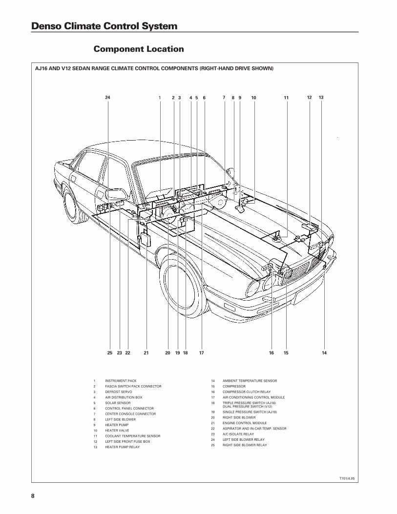
Component Location
T701/4.05
AJ16 AND V12 SEDAN RANGE CLIMATE CONTROL COMPONENTS (RIGHT-HAND DRIVE SHOWN)
1 2 3 4 5 6 7 8 9 10 11 12 13
1415161718192021222325
24
1 INSTRUMENT PACK
2 FASCIA SWITCH PACK CONNECTOR
3 DEFROST SERVO
4 AIR DISTRIBUTION BOX
5 SOLAR SENSOR
6 CONTROL PANEL CONNECTOR
7 CENTER CONSOLE CONNECTOR
8 LEFT SIDE BLOWER
9 HEATER PUMP
10 HEATER VALVE
11 COOLANT TEMPERATURE SENSOR
12 LEFT SIDE FRONT FUSE BOX
13 HEATER PUMP RELAY
14 AMBIENT TEMPERATURE SENSOR
15 COMPRESSOR
16 COMPRESSOR CLUTCH RELAY
17 AIR CONDITIONING CONTROL MODULE
18 TRIPLE PRESSURE SWITCH (AJ16)DUAL PRESSURE SWITCH (V12)
19 SINGLE PRESSURE SWITCH (AJ16)
20 RIGHT SIDE BLOWER
21 ENGINE CONTROL MODULE
22 ASPIRATOR AND IN-CAR TEMP. SENSOR
23 A/C ISOLATE RELAY
24 LEFT SIDE BLOWER RELAY
25 RIGHT SIDE BLOWER RELAY

9
Denso Climate Control System
XK8 CLIMATE CONTROL COMPONENTS
T701/4.06A & B
1 AMBIENT TEMPERATURE SENSOR
2 REFRIGERANT 4-WAY PRESSURE SWITCH
3 RECEIVER / DRIER
4 PLENUM
5 AIR CONDITIONING / HEATER UNIT
6 FASCIA DUCTS
7 RIGHT SIDE BLOWER
8 AIR CONDITIONING CONTROL MODULE
9 CONTROL PANEL
10 LEFT SIDE BLOWER
1 2 3 4 5 6
78111314
15 16
91012
17
1819
11 ASPIRATOR ASSEMBLY
12 SOLAR SENSOR
13 HEATER VALVE AND PUMP
14 COMPRESSOR
15 WINDSHIELD HEATER RELAYS
16 AIR CONDITIONING ISOLATE RELAY
17 BLOWER MOTOR RELAYS
18 DOOR MIRROR HEATER RELAY
19 COMPRESSOR CLUTCH RELAY

10
Denso Climate Control System
Control Module
The air conditioning control module (A/CCM), located on the right side of the air conditioning / heaterunit, controls all system sensing and drive functions.
The A/CCM has two microprocessors: one 8-bitand one 4-bit. The 8-bit microprocessor controlsthe overall system strategy and stores input /output information. The 4-bit microprocessor“conditions” the system signals and processesinformation.
The A/CCM uses discrete components plusanalog-to-digital circuits to interface between themicroprocessors, input sensors and outputdevices. Software programmed into an EPROMis used for control, data and diagnostics.
Ignition switched power activates the A/CCMwhen the ignition is switched to position II.Quiescent current from a battery power supply isused to keep the A/CCM random accessmemory (RAM) active so that diagnostic informa-tion is maintained.
The A/CCM contains four connector sockets.A rough guide to the connector function group-ing is as follows:
Connector
Sedan XK8 Description Function
CC28 AC1 26-way system component drives; compressor clutch status
CC29 AC2 16-way sensor inputs; feedback inputs; vehicle interface
CC30 AC3 12-way sensor inputs; control panel communication;grounds; vehicle interface
CC31 AC4 22-way power supplies; grounds; signal grounds; vehicle interface
Isolate relay
The A/C isolate relay remains energized by the A/CCM for 30 seconds after the ignition is switchedoff to provide battery power for the A/CCM to “park” the system servos.
NOTES
CLIMATE CONTROL MODULE (A/CCM)
T701/4.07
SEDAN XK8
CC28 AC1
CC29 AC2
CC30 AC3
CC31 AC4

11
Denso Climate Control System
System Sensors and Potentiometers: Power Supply and Signal Ground
The climate control system uses multiple sensors to measure and report temperatures and on XJ12and 1997 MY XK8 only, compressor rotation. Feedback potentiometers are used to report the posi-tion of air flow flaps and the desired face level differential position (through 1997 MY only). All of thesensors and potentiometers use a common five volt power supply (reference voltage) from theA/CCM and a common signal ground at the A/CCM.
Sensor and potentiometer power supply and signal ground diagnostic monitoring
The A/CCM monitors the sensor 5 volt power supply circuit for open circuit, high resistance and shortcircuit conditions. The signal ground circuit is monitored for open circuit conditions. If a fault ispresent, a DTC will be flagged.
DTCs: PDU Panel
B1297 none
B1298 none
B1299 none
B1863 none
Refer to the DTC Summary, pages 61 – 64.
NOTES

12
Denso Climate Control System
Control Module
System Diagnostics
The A/CCM continuously monitors the climate control system for faults. If a fault is detected the A/CCMflags a diagnostic trouble code (DTC) corresponding to the fault. All DTCs can be retrieved using PDU.In addition, some fault codes can be displayed on the control panel screen. The PDU DTCs consistof 5 characters; the codes displayed on the control panel are two digit numbers. PDU and panel dis-play fault code information is supplied with the description of the applicable component in thistextbook and in the DTC Summary on pages 61 – 64.
A/CCM power supplies and auxiliary ground diagnostic monitoring
The A/CCM monitors the system power supplies for open circuit, high resistance, and short circuitconditions. The ignition switched ground input signal is monitored for open circuit or high resistanceconditions. If a fault is present, a DTC will be flagged.
DTCs: PDU Panel
B1292 none
B1294 none
B1355 none
B1857 none
Refer to the DTC Summary, pages 61 – 64.
SEDAN: CC31XK8: AC4
1 11
12
1
7
1
9
1
1422
6
12
8
16
13
26
SEDAN: CC30XK8: AC3
SEDAN: CC29XK8: AC2
SEDAN: CC28XK8: AC1
AIR CONDITIONING CONTROL MODULE (A/CCM)
T701/4.08
NOTES

13
Denso Climate Control System
Control Module Pin Out Information
I = Input O = Output SG = Signal ground D = Serial and encoded communications
I/O Sedan XK8 Description
I CC28-1 AC1-1 Compressor clutch status
O CC28-2 AC1-2 Heater valve active
O CC28-3 AC1-3 RH blower motor relay
O CC28-4 AC1-4 LH and RH windshield heater relays
O CC28-5 AC1-5 Door mirror heater relay
O CC28-6 AC1-6 Defrost vent servo motor
O CC28-7 AC1-7 Center vent servo motor
O CC28-8 AC1-8 LH fresh / recirculation vent servo motor
O CC28-9 AC1-9 RH fresh / recirculation vent servo motor
O CC28-12 AC1-12 Footwell vent servo motor
O CC28-13 AC1-13 Cool air bypass vent servo motor
O CC28-14 Not used RH high speed blower relay
O CC28-15 Not used LH high speed blower relay
O CC28-16 AC1-16 LH blower motor relay
O CC28-17 AC1-17 Heater pump relay
O CC28-18 AC1-18 Heated backlight relay
O CC28-19 AC1-19 Defrost vent servo motor
O CC28-20 AC1-20 Center vent servo motor
O CC28-21 AC1-21 LH fresh / recirculation vent servo motor
O CC28-22 AC1-22 RH fresh / recirculation vent servo motor
O CC28-25 AC1-25 Footwell vent servo motor
O CC28-26 AC1-26 Cool air bypass vent servo motor
I CC29-1 AC2-1 Solar sensor feedback
I CC29-2 AC2-2 Center vent potentiometer feedback
I CC29-3 AC2-3 RH recirculation potentiometer feedback
I CC29-5 AC2-5 Cool air bypass potentiometer feedback
I CC29-6 AC2-6 Engine coolant temperature
I CC29-7 AC2-7 RH blower speed feedback
O CC29-8 AC2-8 RH blower speed control drive signal
I CC29-9 AC2-9 Face vent differential temperaturepotentiometer (through 1997 MY)
I CC29-10 AC2-10 Defrost vent potentiometer feedback
I CC29-11 AC2-11 LH recirculation potentiometer feedback
I CC29-13 AC2-13 Footwell vent recirculation potentiometerfeedback
I CC29-15 AC2-15 LH blower speed feedback
O CC29-16 AC2-16 LH blower speed control drive signal
I/O Sedan XK8 Description
O CC30-1 AC3-1 Air conditioning electrical load signal
O CC30-2 AC3-2 Clock
D CC30-3 AC3-3 Serial data output to control panel
I CC30-4 AC3-4 Compressor lock signal(V12 and 1997 MY XK8 only)
I CC30-5 AC3-5 Ambient temperature sensor feedback
I CC30-6 AC3-6 Heater matrix air temp. sensor feedback
D CC30-7 AC3-7 Serial data input from control panel
O CC30-8 AC3-8 Start
CC30-10 — Ground
— AC3-10 Ignition switched power supply(momentary)
I CC30-11 AC3-11 In-car temperature sensor
I CC30-12 AC3-12 Evaporator temperature sensor
CC31-1 AC4-1 Ignition switched B+ power supply
CC31-2 AC4-2 B+ power supply (via A/C isolate relay)
I CC31-3 AC4-3 Ignition switched ground (POS I)
O CC31-4 AC4-4 Control panel battery power supply
CC31-5 AC4-5 B+ power supply (A/CCM memory)
I CC31-6 AC4-6 Engine speed signal
I CC31-7 AC4-7 Load inhibit (V12 and 1997 MY XK8 only)
O CC31-8 AC4-8 Servo potentiometer commonreference voltage
O CC31-9 AC4-9 Compressor clutch on request
D CC31-10 AC4-10 Serial communication input
O CC31-12 AC4-12 Control panel battery power supply
I CC31-13 AC4-13 Ground
O CC31-14 AC4-14 Control panel ground supply
O CC31-15 AC4-15 Isolate relay active
I CC31-16 AC4-16 Vehicle speed signal
I CC31-17 — Refrigerant dual pressure switch
I — AC4-17 Refrigerant 4-way pressure switch
O CC31-18 AC4-18 Aspirator motor power supply
SG CC31-19 AC4-19 Potentiometer common reference ground
I CC31-20 AC4-20 Ground
D CC31-21 AC4-21 Serial communication output
NOTES

14
Denso Climate Control System
CLIMATE CONTROL PANEL DISPLAY
T701/4.09
Climate Control Panel
The control panel is the interface between the driver and the air conditioning control module(A/CCM). It has a 4-bit microprocessor that processes information and converts the selected switchpositions and settings into digital data that is communicated to the A/CCM over a serial data link.
Data transfer between the control panel and the A/CCM occurs in cycles when the “START” signalis received from the A/CCM. The total communication contains 29 “CLOCK” pulses. In order to avoiderrors, the A/CCM must receive two identical data transfers before any action is taken. Power sup-ply to the control panel is provided via the A/CCM when the ignition switch is in position I (auxiliary)or II (ignition).
Control Panel Display
The display gives the driver a visual presentation of the system's current selections and operation:
Blower speed A bar graph displays the blower speed during manual control.
Temperature The interior or exterior temperature is displayed numerically. Exterior tempera-ture is selected by pressing the EXT button:
Momentary press (one beep) – four second display
Long duration press (two beeps) – continuous display
Temperature scale °F (Fahrenheit) or °C (Celsius) is displayed by pressing the °F or °C button.
Exterior temp. EXT is displayed when the exterior temperature is selected. The exterior tem-option perature will continue to be displayed if the system is switched off.
Automatic mode AUTO is displayed when the system is in automatic mode. Any manualoverrides will switch off the AUTO indicator.
Displayed exterior To compensate for heat soak conditions, the displayed exterior temperaturetemperature is stored in memory for one hour after the ignition is switched OFF.
If the ignition is switched ON before one hour has elapsed, and the ambient temperature has risen, thestored temperature is displayed; if the ambient temperature has dropped, the lower temperature is dis-played. When the ignition is switched ON after one hour, the current ambient temperature is displayed.
TEMPERATURE
BLOWER SPEED (MANUAL MODE)
˚F OR ˚C SELECTED
EXTERIOR TEMPERATURE SELECTED
AUTOMATIC MODE SELECTED

15
Denso Climate Control System
Climate Control System ON / OFF
The climate control panel is switched ON by pressing one of the following panel controls:
AUTO AUTO switches the system ON in the automatic mode; AUTO appears on thepanel display. Temperature, blower speed and air distribution are automaticallycontrolled. If heat is required, the blowers will not operate until the engine tem-perature has risen above 30 °C (87 °F), unless defrost is selected. The blowersoperate any time cooling is required. Except in recirculation mode, blowerspeed is linked to vehicle speed to adjust for the ram air effect at higher vehiclespeeds.
A/C A/C switches the system ON in air conditioning mode only. The system usesthe air condition settings in effect the last time air conditioning was used.
DEF DEF switches the system ON in the defrost mode only. Air is directed to thewindshield only. The blowers operate at maximum speed. Temperature isautomatically controlled by the A/CCM.
Push OFF Push OFF switches the system ON in the AUTO mode. AUTO appears on thepanel display.
The climate control system is switched OFF as follows:
Push OFF Push OFF is the only method for switching the system OFF. When push OFFis pressed, the system is switched off and the fresh air or recirculation blowerflaps are set to recirculation, shutting off outside air intake.
NOTES
CLIMATE CONTROL PANEL ON / OFF FUNCTIONS
T701/4.09
SYSTEM ON ANDAUTOMATIC / MANUAL OPERATION
SYSTEM ON ANDAIR CONDITIONING ON / OFF
SYSTEM ON – DEFROST ONLYAND DEFROST SELECT
SYSTEM ON / OFF ANDMANUAL FAN SPEED

16
Denso Climate Control System
Climate Control Panel
Climate Control Panel Switch Functions
Push OFF This switch is a combination switch for manual blower speed control and sys-tem ON / OFF. Pushing the rotary switch provides system ON or OFF. Turningthe switch provides manual blower control and overrides the AUTO controlblower speed functions.
Recirculation Pressing this switch closes off the outside air intake and recirculates cabin air.The LED indicates the status.
Momentary press (one beep) – five minute operation
Long duration press (two beeps) – continuous operation
A/C This switch signals the A/CCM to request air conditioning compressor operationfrom the engine control module. The LED indicates when compressor opera-tion is requested.
AUTO When AUTO is selected (LED on), control of air distribution, blower speed, andinterior temperature is fully automatic. Manual overrides, such as pressing oneof the air distribution buttons, turning the blower speed control, or selectingA/C, will disengage the automatic function. The AUTO LED will go out to indi-cate that a manual override has been selected. When AUTO is pressed again,manual overrides are canceled and full automatic system control is restored.
CLIMATE CONTROL PANEL ON / OFF FUNCTIONS
T701/4.09
˚F / ˚C SELECT
MANUAL RECIRCULATION
SYSTEM ON / OFF ANDMANUAL FAN SPEED
LED DISPLAY
DISPLAY OUTSIDEAIR TEMPERATURE
SYSTEM ON ANDA/C ON / OFF
SYSTEM ON AND AUTOMATIC /MANUAL OPERATION
SYSTEM ON – DEFROST ONLYAND DEFROST SELECT
WINDSHIELD HEATER(OPTIONAL)
HEATED REAR WINDOW
INTERIOR TEMPERATUREINCREASE (1˚ STEPS)
INTERIOR TEMPERATUREDECREASE (1˚ STEPS)
WINDSHIELD ANDFOOT LEVEL
FOOT LEVEL
BI-LEVEL
FACE LEVEL
MANUAL AIR DISTRIBUTION

17
Denso Climate Control System
DEF This switch selects defrost. Maximum blower speed occurs and all air isdirected to the windshield. Blower speed can be reduced by turning the blowerspeed control rotary switch. Temperature is controlled by the A/CCM; however,the temperature can be adjusted by using the temperature selectUP / DOWN switches. The optional heated windshield will also be switched onfor six minutes. If DEF is switched off or the system is switched off before thesix minutes has elapsed, the heated windshield will remain on for the six minutetimed period. The LED indicates the status.
Heated windshield This switch selects the optional windshield electric heater. The heater willoperate for six minutes, then time-out. The LED indicates the status. The wind-shield heater operates only when the engine is running.
Heated backlight This switch selects the backlight and door mirror heaters. The backlight willoperate for 20 minutes and the door mirror heaters will operate for 11 minutes,then time-out. The LED indicates the status. The heated backlight and mirrorheaters operate only when the engine is running.
Interior temperature The temperature select buttons increase or decrease the desired interior tem-perature in 1° increments, °C or °F, as selected.
Manual air Four air distribution manual override buttons are used to override the automaticfunction and distribution override distribute air as the driver selects: FACE, FACEAND FEET (bi-level), FEET ONLY and WINDSHIELD AND FEET. The LED indi-cates the status.
Climate Control Panel Pin Out Information
I/O Sedan XK8 Description
I CC2-1 FC43-1 Clock
I CC2-2 FC43-2 Start
O CC2-3 FC43-3 Serial data to AC/CM
I CC2-4 FC43-4 Serial data from AC/CM
I CC2-5 FC43-5 Battery power supply
I CC2-6 FC43-6 Battery power supply
I CC2-7 FC43-7 Ground supply
I CC2-8 FC43-8 Locate illumination power supply
I CC2-9 FC43-9 Dimmer override power supply
NOTES
CLIMATE CONTROL PANEL CONNECTOR
T701/4.10
16
12 7

18
Denso Climate Control System
Air Conditioning / Refrigeration System
The Jaguar air conditioning system employs environmentally friendly R134a refrigerant. The layoutof the system is conventional; however, there are minor differences between the Sedan and XK8 in-stallations.
NOTES
BASIC AIR CONDITIONING SYSTEM
T701/4.11
HFC 134a EVAPORATES
COOLED AIR
EXPANSIONVALVE
LIQUIDREFRIGERANT
HFC 134a LIQUEFIES
RECEIVER / DRIER
HIGH-PRESSURE HIGH-TEMPERATURE LIQUIDAIR
CONDENSER
COOLING FANCOMPRESSOR
HIGH-PRESSURE HIGH-TEMPERATURE GAS
LOW-PRESSURELOW TEMPERATURE GAS
BLOWER
EVAPORATOR
LOW-PRESSURELOW-TEMPERATURE
LIQUID
AIR AIR
TEMPERATURE
SENSING BULB

19
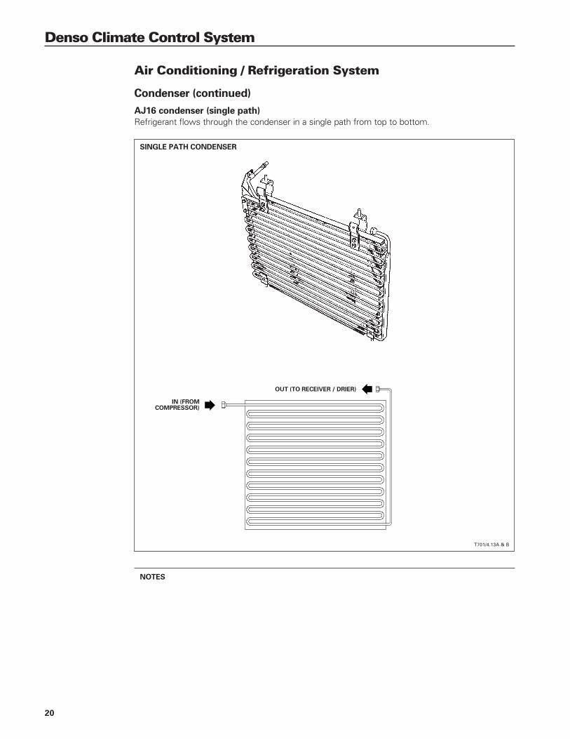
Denso Climate Control System
Condenser
The condenser is part of the vehicle cooling pack. Located in front of the radiator, the condenser isthe system high-side heat exchanger. In the condenser, the high temperature / high pressure refrig-erant (in vapor form) condenses into a high pressure liquid. The condenser is constructed as a tubeand fin unit similar to the radiator. Refrigerant flow through the condenser differs between the AJ16and the V12, AJV8 condensers.
NOTES
AJ16 SC COOLING PACK
T701/4.12
RECEIVER / DRIER
RADIATOR
SUPERCHARGERCOOLER
CONDENSER
20
Denso Climate Control System
Air Conditioning / Refrigeration System
Condenser (continued)
AJ16 condenser (single path)
Refrigerant flows through the condenser in a single path from top to bottom.
NOTES
SINGLE PATH CONDENSER
T701/4.13A & B
IN (FROMCOMPRESSOR)
OUT (TO RECEIVER / DRIER)

21
Denso Climate Control System
T701/4.14A & B
IN (FROMCOMPRESSOR) OUT (TO RECEIVER / DRIER)
V12 and AJV8 condensers (multi path)
Refrigerant flows through the condenser in separate paths starting at one side and exiting at the other.
NOTES
MULTI-PATH CONDENSER (V12 SHOWN)

22
Denso Climate Control System
Air Conditioning / Refrigeration System
Receiver / Drier
The receiver / drier stores liquid refrigerant to allowfor changes in evaporator demand. In addition,it filters the refrigerant and removes moisture.Due to the characteristics of R134a, no sightglass is provided.
On AJ16 an V12 installations the receiver / drieris horizontally mounted at the top of the con-denser. The vertically mounted receiver / drierfor AJV8 installations is located near the radiatoron the right side of the engine compartment.The high side charge port is on top of thereceiver / drier.
NOTES
AJ16 AND V12 RECEIVER / DRIER LOCATION
AJV8 RECEIVER / DRIER LOCATION
T701/4.15A & B
T701/4.16
CONDENSER
REFRIGERANT SWITCH
RADIATOR
RECEIVER / DRIER
CONDENSER
RECEIVER / DRIER

23
Denso Climate Control System
Expansion Valve
The expansion valve is located within the air con-ditioning / heater unit on the evaporator inlet.The expansion valve meters the refrigerant flowinto the evaporator in proportion to the evapora-tor outlet temperature and refrigerant pressure.
Evaporator
The evaporator is located within the air condition-ing / heater unit behind the center console. It isthe system low side heat exchanger. As the re-frigerant is metered into the low pressure of theevaporator (compressor suction) it absorbs heatfrom the cabin air via the evaporator fins andchanges to a vapor.
NOTES
TYPICAL EXTERNAL EQUALIZING EXPANSION VALVE
EVAPORATOR
T701/4.17
T701/4.18
TEMPERATURESENSOR
INLET
OUTLET
TEMPERATURESENSING BULB

24
Denso Climate Control System
Air Conditioning / Refrigeration System
Compressor
The refrigerant is compressed and circulated by a ten-cylinder swash-plate type compressor.The compressor drive shaft connects to a swash plate that operates five double-ended pistons. Thiscompressor design allows one end of each piston to be on the suction stroke while the other end ison the compression stroke, resulting in smooth, quiet operation.
As a safety feature, a pressure relief valve in the compressor vents refrigerant at 41 bar (594 psi) andresets at approximately 28 bar (406 psi).
NOTES
COMPRESSOR
COMPRESSOR OPERATION
T701/4.19
T701/4.20
SWASH PLATE
PISTON
DISCHARGEVALVE
SUCTIONVALVE
SUCTIONVALVE
DISCHARGEVALVE
SUCTIONVALVE
DISCHARGEVALVE

25
Denso Climate Control System
AJV8 COMPRESSOR LOCATION
AJ16 COMPRESSOR LOCATION
V12 COMPRESSOR LOCATION
T701/4.21
T701/4.23
T701/4.22

26
Denso Climate Control System
COMPRESSOR DRIVES
AJ16 V12
AJV8
T701/4.24, 4.25, 4.26
Air Conditioning / Refrigeration System
Compressor (continued)
Compressor drive belt adjustment
AJ16 and V12 Both AJ16 and V12 engine drive belts use adjustable idler pulleys for belt tensioning.The AJ16 tensioner operates in a slotted bracket. The V12 tensioner operates on a pivoting bracket.
AJV8 AJV8 engine applications use a multi-ribbed serpentine belt with an automatic belt tensioner.A belt wear indicator on the tensioner indicates the need for belt replacement. Refer to the ServiceManual for inspection and belt replacement procedures.
NOTES
27
Denso Climate Control System
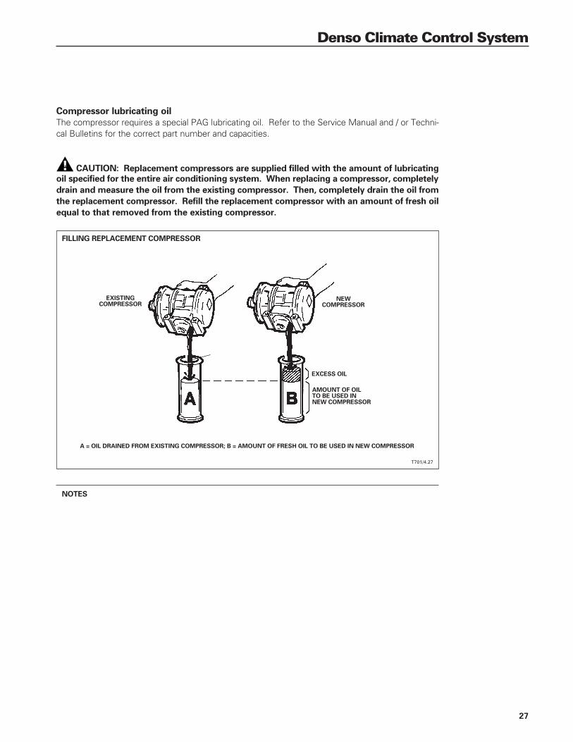
Compressor lubricating oil
The compressor requires a special PAG lubricating oil. Refer to the Service Manual and / or Techni-cal Bulletins for the correct part number and capacities.
CAUTION: Replacement compressors are supplied filled with the amount of lubricating
oil specified for the entire air conditioning system. When replacing a compressor, completely
drain and measure the oil from the existing compressor. Then, completely drain the oil from
the replacement compressor. Refill the replacement compressor with an amount of fresh oil
equal to that removed from the existing compressor.
NOTES
FILLING REPLACEMENT COMPRESSOR
T701/4.27
NEWCOMPRESSOR
EXCESS OIL
EXISTINGCOMPRESSOR
AMOUNT OF OILTO BE USED INNEW COMPRESSOR
A = OIL DRAINED FROM EXISTING COMPRESSOR; B = AMOUNT OF FRESH OIL TO BE USED IN NEW COMPRESSOR

28
Denso Climate Control System
Air Conditioning / Refrigeration System
Compressor Clutch Control
The compressor is switched on or off depending on the evaporator temperature and the operatingdemands of the climate control system and the engine. When the climate control system is switchedon, the A/CCM “requests” that the engine control module (ECM) switch on the compressor clutch.If engine operating parameters are within an acceptable range, the ECM applies a ground to the com-pressor clutch relay coil to switch on the compressor.
AJ16
The ECM may delay compressor clutch engagement for four seconds depending on engine operat-ing temperature.
V12
The ECM inhibits compressor operation under the following conditions:
• Engine coolant temperature above 120 °C (248 °F).
• Engine speed below 500 rpm – the compressor is switched on again 20 seconds after the enginespeed reaches 566 rpm.
• Full throttle operation – the compressor is switched off for 15 seconds. It is switched on againafter 15 seconds or when the ECM no longer “sees” full throttle.
AJV8
The ECM inhibits compressor operation under the following conditions:
• Engine coolant temperatures above 119 ºC (246 ºF)
• At idle speed the compressor is momentarily inhibited (50 ms) to allow the ECM to increase theidle speed to compensate for the compressor load.
• At high engine load (WOT), the compressor is inhibited.
If the compressor clutch is engaged and one of the above conditions occurs, the ECM disengages theclutch until the inhibiting condition is corrected.
Compressor clutch diagnostic monitoring
The A/CCM uses the B+ “compressor on” input to monitor the integrity of the compressor clutchdrive circuit. If all compressor operating conditions are met and a request signal has been sent to theECM, the A/CCM should receive the B+ signal. If the B+ signal is not received, a fault condition isassumed and a DTC will be flagged, however; the A/CCM will continue to request the ECM for com-pressor operation.
In V12 and AJV8 systems through the 1997 MY, the A/CCM monitors for compressor lock conditionswhen the B+ signal is present. No default value is used for this signal. There is no compressor locksensor in AJ16 systems.
DTCs: PDU Panel
B1969 none
Refer to the DTC Summary, pages 61 – 64.
NOTES

29
Denso Climate Control System
AJV8 COMPRESSOR CLUTCH CONTROL
T701/4.29
AJ16, AND V12 COMPRESSOR CLUTCH CONTROL
T701/4.28
COMPRESSOR ON29 – 392 PSI(2 – 27 BAR)
COMPRESSOR ON> 32˚F (0˚C)
COMPRESSORCLUTCH
REQUEST
COMPRESSORCLUTCH
CONTROL
CONTACTCIRCUIT
COILCIRCUIT
LOCK SENSOR(V12 ONLY)
CONTROL PANEL
REFRIGERANT DUAL PRESSURE SWITCH(AJ16: PART OF TRIPLE SWITCH)
EVAPORATORTEMPERATURE SENSOR
A/C CONTROL MODULEENGINE CONTROL MODULE
COMPRESSOR CLUTCH RELAY
COMPRESSOR CLUTCH
BATTERYPOWER SUPPLY
IGNITIONPOWER SUPPLY
COMPRESSOR REQUEST
ENGINE SPEED
COMPRESSOR SPEED (V12 ONLY)
COMPRESSOR ON / OFF
COMPRESSOR ON
ENGINE LOAD
LOAD INHIBIT (V12)
ELECTRICAL LOAD
RELAY COIL DRIVE (GND)
INSTRUMENT PACK
ENGINE TEMP.
COMPRESSOR ON2 – 30 BAR
(29 – 435 PSI)
COMPRESSOR ON> 0˚ C (32˚ F)
COMPRESSORCLUTCH
REQUEST
COMPRESSORCLUTCH
CONTROL
CONTACTCIRCUIT
COILCIRCUIT
LOCK SENSOR(1997 MY)
CONTROL PANEL
REFRIGERANTPRESSURE SWITCH
EVAPORATORTEMPERATURE
SENSOR
A/C CONTROL MODULE ENGINE CONTROL MODULE
COMPRESSOR CLUTCH RELAY
COMPRESSOR CLUTCH
BATTERYPOWER SUPPLY
IGNITIONPOWER SUPPLY
COMPRESSOR REQUEST
COMPRESSOR SPEED (THROUGH 1997 MY)
COMPRESSOR ON
COMPRESSOR ON
ELECTRICAL LOAD
RELAY COIL DRIVE (GND)
INSTRUMENT PACK
ENGINE TEMP.
ENGINE SPEED
LOAD INHIBIT

30
Denso Climate Control System
Air Conditioning / Refrigeration System
Compressor Lock Sensor (V12 and AJV8 through 1997 MY Only)
Because the power steering pump and air condi-tioning compressor are driven by the same belton the V12 and the AJV8, a compressor locksensor is installed to provide the A/CCM with aninput to verify correct operation. The compres-sor lock sensor, similar to an ABS wheel speedsensor, provides a pulsed signal indicating com-pressor pulley speed. The A/CCM compares thepulley speed to the engine speed input receivedfrom the ECM. If the pulley speed indicates beltslippage, the A/CCM cancels the A/C request tothe ECM to protect against drive belt failure.The A/CCM also flashes the control panel A/Cswitch LED as an immediate warning and flagsDTC B1862.
The compressor lock sensor is deleted on AJV8applications after the 1997 MY.
Compressor lock sensor diagnostic monitoring
The A/CCM monitors the compressor lock sensing circuit for open circuit and short circuit conditions.If a fault is present, a DTC will be flagged. No default value is used for this signal.
DTCs: PDU Panel
B1862 22
Refer to the DTC Summary, pages 61 – 64.
NOTES
V12 DRIVE BELT
AJV8 DRIVE BELT
T701/4.25
T701/4.26
COMPRESSOR
COMPRESSOR

31
Denso Climate Control System
Refrigerant Pressure Switches
AJ16 and V12
If the refrigerant pressure is low or high, the refrigerant dual pressure switch contacts will open tosignal the A/CCM to switch the compressor off. Low pressure can result from a system leak or lowambient temperature. High pressure can be cause by poor system performance, system blockage,or high ambient temperature.
On AJ16, the pressure switch is part of the triple pressure switch. Refrigerant pressure must bebetween 2 – 27 bar (29 – 392 psi) for the switch contacts to remain closed and provide a groundsignal to the A/CCM. The radiator cooling fans are switched from low to high speed by the otherset of contacts in the triple pressure switch. Refer to AJ16 Cooling Fan Control, page 34.
The refrigerant pressure switch(es) are located close to the engine bulkhead on the right side.
2 – 27 BAR
20 BARWU B B
B
BKUB
REFRIGERANTTRIPLE PRESSURE
SWITCH
P
B
2 – 27 BAR BKUB
REFRIGERANTDUAL PRESSURE
SWITCH
P
B
B
AJ16 REFRIGERANT PRESSURE SWITCHES
V12 REFRIGERANT PRESSURE SWITCH
T701/4.30A & B
T701/4.31A & B

32
Denso Climate Control System
Air Conditioning / Refrigeration System
Refrigerant Pressure Switches (continued)
AJV8
A single 4-way pressure switch is located on the high pressure line between the compressor andcondenser to monitor refrigerant pressure. The three contact sets in the switch work with the A/CCMand ECM to control compressor clutch engagement and radiator cooling fan speed. Refer to AJV8Cooling Fan Control, page 36.
The refrigerant pressure must be between 2 – 30 bar (29 – 435 psi) for the switch contacts to remainclosed and provide a signal to the A/CCM allowing the A/C request signal to the ECM.
Refrigerant pressure switch diagnostic monitoring
The A/CCM monitors pressure switch operation by comparing the ambient temperature to the switchcontact position. During normal ambient temperature conditions the switch contacts should be closed.If the switch circuit is open during normal conditions, DTC B1858 is flagged.
At ambient temperatures below -10 °C (14 °F), refrigerant pressure should drop below 2 bar (29 psi)and open the switch contacts. If the contacts are closed or there is a short circuit to ground, DTCB1861 is flagged. No default value is used for this signal.
DTCs: PDU Panel Condition
B1858 23 Open circuit
B1861 23 Closed circuit
Refer to the DTC Summary, pages 61 – 64.
NOTES
2 – 30 BAR
20 BAR
12 BAR
WU
YW
BK
BKUB
REFRIGERANT4-WAY PRESSURE
SWITCH
P
BK
BK BK
AJV8 REFRIGERANT PRESSURE SWITCH
T701/4.32A & B

33
Denso Climate Control System
Evaporator Temperature Sensor
The evaporator temperature sensor, located onthe left side of the evaporator, is an NTC (nega-tive temperature coefficient) sensor that providesa voltage signal to the A/CCM. If the evaporatortemperature falls to 0 °C (32 °F), the A/CCM willcancel the A/C request to the ECM and switchoff the compressor to prevent the evaporatormatrix from freezing. When the evaporator tem-perature rises to approximately 3 °C (37.5 °F),the A/CCM will again request A/C from the ECM.
Approximate temperature versus voltage
Temperature Voltage
°C °F
32 – 37 90 – 100 1.50
26 – 31 79 – 89 1.75
21 – 25 70 – 78 2.00
17 – 21 63 – 70 2.25
13 – 18 56 – 65 2.50
08 – 13 47 – 56 2.75
05 – 09 42 – 49 3.00
01 – 04 35 – 40 3.25
- 05 – 0 23 – 32 3.50
Evaporator temperature sensor diagnostic monitoring
The A/CCM monitors the evaporator temperature sensing circuit for open circuit, high resistance, andshort circuit conditions. If a fault is present, a DTC will be flagged.
A default value of 0 °C (32 °F) is substituted by the A/CCM if an evaporator temperature sensor faultis present. The compressor will not run when an evaporator temperature sensor fault is flagged.
DTCs: PDU Panel
B1946 13
B1947 13
Refer to the DTC Summary, pages 61 – 64.
NOTES
EVAPORATOR TEMPERATURE SENSOR
T701/4.33

34
Denso Climate Control System
Cooling Fan Control
Cooling Fan Control – AJ16
The radiator and condenser cooling fans are controlled by both radiator coolant temperature and airconditioning refrigerant pressure. Fan operation depends on the cooling air flow requirement. Atlower coolant temperature / refrigerant pressure, both fans operate at low speed (in series); at highcoolant temperature / refrigerant pressure, both fans operate at high speed (in parallel). The refrigeranttriple pressure switch contains a pressure contact set for high speed fan drive. A separate refriger-ant single pressure switch is used for low speed fan drive. Fan speed switching is accomplishedthrough a fan control relay module. For engine coolant temperature, a radiator thermostatic switchwith two sets of contacts – one for slow speed fan drive and one for high speed fan drive is used.
Low speed fan operation
Both fans run at low speed (in series) when the radiator coolant temperature reaches 86 °C (187 °F)and / or the refrigerant pressure reaches 12 bar (174 psi ).
High speed fan operation
Both fans run at high speed (in parallel) when the radiator coolant temperature reaches 100 °C(212 °F) and / or the refrigerant pressure reaches 20 bar (290 psi).
Beginning with VIN 761570, the refrigerant single pressure switch has been deleted from AJ16 en-gine vehicles. The cooling fans run continuously when the ignition is switched to position II.
Cooling Fan Control – V12
The radiator and condenser cooling fans are controlled by radiator coolant temperature. The V12 usesthe same dual temperature radiator thermostatic switch and fan control relay module as the AJ16.
Low speed fan operation
Both fans run at low speed when the radiator coolant temperature reaches 86 °C (187 °F).
High speed fan operation
Both fans run at high speed when the radiator coolant temperature reaches 100 °C (212 °F).
NOTES

35
Denso Climate Control System
AJ16 COOLING FAN CONTROL UP TO VIN 761569
AJ16 COOLING FAN CONTROL FROM VIN 761570
T701/4.34
T701/4.35
HIGH SPEED ON290 PSI >
(20 BAR >)
LOW SPEEDFAN RELAY
REFRIGERANTSINGLE PRESSURE SWITCH
REFRIGERANTDUAL PRESSURE SWITCH(PART OF TRIPLE SWITCH)
RADIATORTHERMOSTATIC SWITCH
FAN CONTROLRELAY MODULE
RIGHT FAN
LEFT FAN
HIGH SPEEDFAN RELAY
LOW SPEED ON187˚F (86˚C) >
HIGH SPEED ON212˚F (100˚C) >
LOW SPEED ON147 PSI >
(12 BAR >)
HIGH SPEED ON290 PSI >
(20 BAR >)
LOW SPEEDFAN RELAY
REFRIGERANT
DUAL PRESSURE SWITCH
(PART OF TRIPLE SWITCH)
RADIATOR
THERMOSTATIC SWITCH
IGNITION SWITCHED B+
FAN CONTROL
RELAY MODULE
RIGHT FAN
LEFT FAN
HIGH SPEEDFAN RELAY
LOW SPEED ON187˚F (86˚C) >
HIGH SPEED ON212˚F (100˚C) >

36
Denso Climate Control System
Cooling Fan Control
Cooling Fan Control – AJV8
The radiator / condenser cooling fans are controlled by the ECM via the fan control relay module usinginputs from the engine coolant temperature sensor (ECT) and the 4-way refrigerant pressure switch12 bar (174 psi) and 20 bar (290 psi) switch elements. At lower coolant temperatures / refrigerant pres-sures the fans operate at low speed (series). At high coolant temperatures / refrigerant pressures thefans operate at high speed (parallel). As the ECM switches the fan speeds, an overlap between switchon / switch off points prevents “hunting” between the fan modes
XK8 radiator fan switching points
Fan Speed Engine coolant temperature Refrigerant pressure
ON OFF ON OFF
Low 90 ºC (194 ºF) 86 ºC (187 ºF) 12 bar (174 psi) 8 bar (116 psi)
Fast 97.5 ºC (207.5 ºF) 93.5 ºC (200.5 ºF) 20 bar (290 psi) 17.5 bar (254 psi)
XJ8 radiator fan switching points
Fan Speed Engine coolant temperature Refrigerant pressure
ON OFF ON OFF
Low 90 ºC (194 ºF) 86 ºC (187 ºF) 12 bar (174 psi) 8 bar (116 psi)
Fast 97.5 ºC (207.5 ºF) 93.5 ºC (200.5 ºF) 22 bar (319 psi) 17.5 bar (254 psi)
On all vehicles, when the engine is switched off, the ECM remains powered up for a few secondsto complete EMS adaptions. If the fans are operating when the engine is switched off, the ECM con-tinues to drive the fans for 5 minutes or until the coolant temperature decreases to a preset value. Ifthe fans are off when the engine is switched off and the coolant temperature rises to the switch-onpoint during the time the ECM is still powered, it will switch the fans on. The fans will operate for fiveminutes or until the coolant temperature decreases to a preset value.
NOTES

37
Denso Climate Control System
T701/4.36
AJV8 COOLING FAN CONTROL
LOW SPEEDFAN RELAY
FANCONTROL
FAN CONTROLRELAY MODULE
RIGHT FAN
LEFT FAN
HIGH SPEEDFAN RELAY
LOW SPEED ON12 BAR (174 PSI)
HIGH SPEED ON22 BAR (319 PSI)
ENGINE CONTROLMODULE
REFRIGERANT 4-WAYPRESSURE SWITCH
ENGINE COOLANTTEMPERATURE SENSOR

38
Denso Climate Control System
Heating System
The Jaguar Climate Control System employs engine coolant to provide cabin heat. An electric pumpconstantly circulates engine coolant through the heater matrix when the engine is running. An A/CCMcontrolled heater valve maintains the heater matrix at the optimum temperature required to achievethe selected cabin temperature.
The AJV8 heating system functions similarly to the AJ16 and V12 heating systems. The AJV8 lowvolume cooling system design requires two non-return valves to maintain correct coolant flow under allengine operating conditions. At low engine speeds, engine coolant flow pressure is less than heaterpump pressure. The non-return valve in the engine cooling system prevents the heater pump from re-circulating coolant against the normal flow of engine coolant. The heater circuit non-return valve preventshot engine coolant from flowing back into the heater matrix after the engine is switched off.
T701/4.37
AJ16 NA COOLING SYSTEM
T701/4.38
AJV8 NA COOLING SYSTEM
HEATER VALVE
EXPANSION TANK
RADIATOR
THERMOSTAT
HEATERMATRIX
HEATER PUMP
HEATER PUMP
HEATERMATRIX
NON-RETURNVALVE
NON-RETURNVALVE
THERMOSTAT
RADIATOR
HEATERVALVE

39
Denso Climate Control System
Heater Pump
The pump is operated continuously by theA/CCM when the A/CCM receives an enginespeed signal and the engine coolant temperatureis above 30 °C (86 °F) ± 10 °C (18 °F). The A/CCM grounds the heater pump relay coil circuitto activate the pump. If the ignition is switchedon and the engine is not running, the pump isswitched off.
Heater pump diagnostic monitoring
Heater pump diagnostic monitoring occurs onlyon 1995 MY vehicles up to VIN 739425. Thesevehicles use a high current draw motor with theground circuit completed through the A/CCM.By monitoring the ground voltage, the A/CCMcan detect when a pump motor failure has oc-curred (pump locked or ground circuit open).Vehicles from VIN 739426 use a lower currentdraw motor and no A/CCM diagnostic monitor-ing. The pump motor ground circuit is com-pleted directly to ground.
DTCs: PDU Panel
B1968 none
Refer to the DTC Summary, pages 61 – 64.
NOTES
T701/4.39
HEATER VALVE
HEATERPUMP
HEATERMATRIX
T701/4.40
HEATER PUMP AND VALVE (AJ16, V12 SHOWN)
AJ16 AND V12 HEATER COOLANT FLOW
T701/4.41
AJV8 HEATER COOLANT FLOW
HEATER VALVE
HEATER PUMP
HEATER PUMP
SUPPLY
RETURN
HEATERMATRIX
HEATERNON-RETURN VALVE
ENGINENON-RETURN VALVE
HEATERVALVE

40
Denso Climate Control System
Heating System
Heater Valve
Coolant circulation to the heater matrix is controlled through a variable duty cycle valve. The A/CCMdrives the valve to fully open or closed to control the heater matrix temperature.
The A/CCM drives the valve with a 12 volt, sixsecond duty cycle signal. The A/CCM increasesor decreases the length of the 12 volt signalwithin the duty cycle to achieve the requiredheater matrix temperature. If the drive circuitfails (open circuit), the valve defaults to the openposition to allow full engine coolant flow to theheater matrix.
The A/CCM uses the control panel settings andthe heater matrix temperature sensor input signalsto achieve the optimum heater matrix temperature.To prevent the circulation of cool engine coolantthrough the heater matrix, the heater valve is drivenclosed during the following conditions:
Engine coolant temperature below86 °F (30 °C) ± 18 °F (10 °C)
No engine speed signal present
The A/CCM does not monitor the heater valvecircuit for diagnostics.
NOTES
HEATER VALVE DRIVE SIGNALS
T701/4.43
T701/4.42A & B
HEATER VALVE
ENGINE
ENGINE
HEATER
HEATER
COLD: NO COOLANT FLOWSTO THE HEATER
HOT: ENGINE COOLANT FLOWSTHROUGH THE VALVE TO THE HEATER
ENGINE
ENGINE
HEATER
HEATER
6 SECONDS
SYSTEM BLEND
OPEN (0V)
CLOSED (12V)50%
50%
COOLING REQUIRED
OPEN (0V)
CLOSED (12V)80%
20%
HEATING REQUIRED
OPEN (0V)
CLOSED (12V)20%
80%

41
Denso Climate Control System
Heater matrix sensor
The NTC (negative temperature coefficient) heater matrix sensor, located on the right side of theheater matrix in the air conditioning / heater unit, provides the A/CCM with a voltage signal represent-ing the heater matrix outlet air temperature. The heater matrix air temperature is one of the inputsused by the A/CCM to control the operation of the heater valve.
Approximate air temperature versus voltage:
Temperature Voltage
°C °F
67 – 73 152 – 163 0.75
57 – 64 136 – 147 1.00
50 – 56 123 – 133 1.25
43 – 48 109 – 118 1.50
37 – 42 98 – 108 1.75
32 – 36 89 – 97 2.00
27 – 31 81 – 88 2.25
23 – 26 74 – 79 2.50
18 – 22 66 – 72 2.75
14 – 17 57 – 64 3.00
10 – 13 50 – 56 3.25
Heater matrix sensor diagnostic monitoring
The A/CCM monitors the heater matrix sensing circuit for open circuit, high resistance, and short circuitconditions. If a fault is present, a DTC will be flagged.
A default value of 45 °C (113 °F) is substituted by the A/CCM if a heater matrix air temperature sen-sor fault is present.
DTCs: PDU Panel
B1966 15
B1967 15
Refer to the DTC Summary, pages 61 – 64.
NOTES
HEATER MATRIX SENSOR
T701/4.44

42
Denso Climate Control System
Air Conditioning / Heater Unit
The air conditioning / heater unit is located behind the fascia and is connected by ducts to the rightand left blowers. The unit directs air into the cabin at the desired temperature via a series of servomotor operated flaps. The position of the flaps is fed back to the A/CCM by non adjustable potenti-ometers integrated with the servo motors. The air conditioning / heater unit directs outlet air to thevarious cabin vents. The air distribution box, located on top of the air conditioning / heater unit, directsair to the windshield, side vents and face vents.
NOTES
AIR CONDITIONING / HEATER UNIT
AIR DISTRIBUTION BOX
T701/4.46
T701/4.45
SERVOSTO AIR DISTRIBUTION BOX
OUTLETS
FROM BLOWERS(1 EACH SIDE)
FROMAIR CONDITIONING / HEATER UNIT

43
Denso Climate Control System
OUTLET AIR TEMPERATURE AND FLOW
T701/4.47
NOTES
FACE VENTS
HEATER MATRIX
REARFACE
REARFEET
FRONTFEET
AIR IN(FROM BLOWER)
EVAPORATOR
COOL AIRBYPASS
SIDE WINDOW VENTS
WINDSHIELD

44
Denso Climate Control System
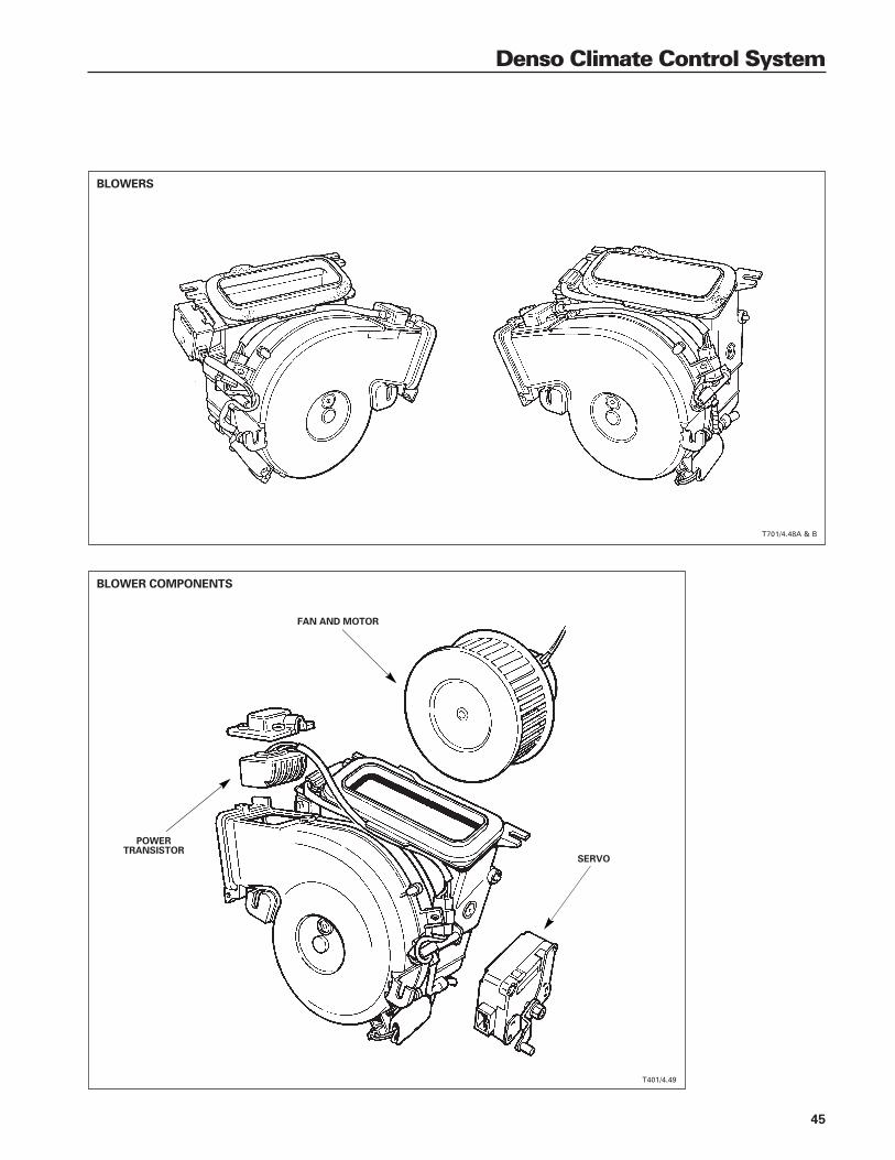
Air Conditioning / Heater Unit
Blowers
The blower assemblies each contain a motor, fan, servo and fresh air / recirculation flap. They con-nect to either side of the air conditioning / heater unit with ducts. Each blower incorporates a powertransistor assembly to regulate air flow output volume. The A/CCM varies the voltage applied to thebase of the power transistor to vary the blower motor speed and thus the air flow output volume.During normal operation, power is supplied to the blower motors via the blower motor relay. Themotor ground is completed by the power transistor circuit to provide varying blower motor speed.When maximum blower output is required, the A/CCM activates the high speed relay, which switchesthe blower motor ground circuit directly to ground and the motor runs at maximum speed.
In AUTO mode, blower motor variable speed is controlled automatically by the A/CCM. In manual con-trol, 11 speed steps are available. Through the 1997 MY, to compensate for the effect of ram air onthe air intakes, the A/CCM adjusts blower speed at vehicle speed above 25 mph (40 km/h). Blowerspeed compensation is canceled during the following conditions:
• Maximum blower speed required
• Fresh / recirc flaps positioned to recirculation
• DEFROST selected
• AUTO – full cooling required (fresh / recirc flaps positioned to recirculation)
In the heating mode, blower operation is canceled by the A/CCM until the engine coolant tempera-ture reaches 30 °C (86 °F) to prevent cold air distribution. The blowers operate at all times in thecooling and defrost modes.
The A/CCM does not monitor the blower motor circuits for diagnostics, however; the A/CCM receivesa feedback signal from the power transistor circuit that indicates blower motor speed. This signal isused to adjust blower speed. If a fault occurs in the blower speed feedback circuit, the A/CCM usesa default speed that depends on the speed selected when the fault occurred. If the equivalent speedwas above 7/8 bar segments, the A/CCM drives the blower motors at maximum speed; if the equiva-lent speed was below 7/8 bar segments, the blower motors are switched off.
The electrical load placed on the vehicle charging system by high speed blower operation is compen-sated for by the ECM (engine control module). Refer to Climate Control Electrical Load, page 56.
NOTES
45
Denso Climate Control System
BLOWERS
T701/4.48A & B
T401/4.49
BLOWER COMPONENTS
POWERTRANSISTOR
FAN AND MOTOR
SERVO

46
Denso Climate Control System
Air Conditioning / Heater Unit
Cabin Air Distribution
Air is distributed to the cabin from multiple vents located at the face level, foot level, windshield, sidewindows, rear foot wells and rear center console.
Face Vent Differential Temperature Control (through 1997 MY Only)
The face vent differential control is a potentiometer that provides the A/CCM with a feedback voltageto indicate the face level differential air temperature selected by the driver. The A/CCM adjusts theposition of the upper cool air bypass flap to meet the desired selection. The resistance range of thepotentiometer is nominally 2 – 8 kΩ:
Minimum differential (RED) 8 kΩ ± 10% = 1 volt (wiper feedback voltage)
Maximum differential (BLUE) 2 kΩ ± 10% = 4 volt (wiper feedback voltage)
Face vent differential temperature control diagnostic monitoring
The A/CCM monitors the face vent differential temperature control circuit for open circuit, high resis-tance, and short circuit conditions. If a fault is present, a DTC will be flagged.
No default value is used for face vent differential control circuit failure.
DTCs: PDU Panel
B1849 24
B1852 24
Refer to the DTC Summary, pages 61 – 64.
NOTES
T701/4.50A & B
T701/4.51
AIR DISTRIBUTION
SEDAN RANGE XK8
FACE VENT DIFFERENTIAL TEMPERATURE CONTROL (THROUGH 1997 MY)

47
Denso Climate Control System
T701/4.53
T701/4.52
DEFROST SELECTED
FACE SELECTED
COOL / WARM AIR OUT
AMBIENT AIR IN
BLEND AIR
COOL / WARM AIR OUT
AMBIENT AIR IN
BLEND AIR
Air Distribution

48
Denso Climate Control System
Air Conditioning / Heater Unit
Air Distribution (continued)
FACE / FEET SELECTED (BI-LEVEL): MINIMUM TEMPERATURE DIFFERENTIAL (THROUGH 1997 MY ONLY)
FACE / FEET SELECTED (BI-LEVEL): MAXIMUM TEMPERATURE DIFFERENTIAL (THROUGH 1997 MY ONLY)
T701/4.55
T701/4.54
COOL / WARM AIR OUT
AMBIENT AIR IN
BLEND AIR
COOL / WARM AIR OUT
AMBIENT AIR IN
BLEND AIR

49
Denso Climate Control System
FEET SELECTED
DEMIST SELECTED
T701/4.57
T701/4.56
COOL / WARM AIR OUT
AMBIENT AIR IN
BLEND AIR
COOL / WARM AIR OUT
AMBIENT AIR IN
BLEND AIR

50
Denso Climate Control System
Air Conditioning / Heater Unit
Servos and Feedback Potentiometers
Six air flow control flap servo assemblies areused in the system:
• Defrost vent • Cool air bypass
• Center vent • Footwell vent
• Left fresh / recirc flap (blower intake)
• Right fresh / recirc flap (blower intake)
Each servo incorporates a feedback potentiom-eter that provides the A/CCM with a feedbackvoltage that indicates the position of the air flowflap. The resistance range of the potentiometersis nominally 2 – 5 kΩ:
Flap closed 5 kΩ ± 10% = 1 volt(wiper feedback voltage)
Flap open 2 kΩ ± 10% = 4 volt(wiper feedback voltage)
Servos and feedback potentiometers diagnostic monitoring
The A/CCM monitors the feedback potentiometer sensing (wiper) circuits for open circuit, high resis-tance and short circuit conditions. If a fault is present, a DTC will be flagged. In addition, the A/CCMmonitors the time required for each servo to position its flap. If the flap does not reach the requiredposition within 30 seconds, a DTC is flagged.
No default values are used for servo / potentiometer circuit failures.
DTCs: PDU Panel Component
B1262 44 Defrost vent position
B1268 34 Defrost feedback potentiometer
B1271 34 Defrost feedback potentiometer
B1263 45 Center vent position
B1272 35 Center feedback potentiometer
B1275 35 Center feedback potentiometer
B1264 46 Footwell vent position
B1276 36 Footwell feedback potentiometer
B1279 36 Footwell feedback potentiometer
B1265 43 Cool air bypass position
B1280 33 Cool air bypass feedback potentiometer
B1283 33 Cool air bypass feedback potentiometer
B1266 41 Left fresh / recirculation position
B1287 31 Left fresh / recirculation feedback potentiometer
B1287 31 Left fresh / recirculation feedback potentiometer
B1267 42 Right fresh / recirculation position
B1288 32 Right fresh / recirculation feedback potentiometer
B1291 32 Right fresh / recirculation feedback potentiometer
Refer to the DTC Summary, pages 61 – 64.
SERVO ASSEMBLY
T701/4.58

51
Denso Climate Control System
Temperature Control Sensors
The A/CCM uses the temperature control sensor inputs to determine the temperature and volume ofair required to maintain the selected interior temperature of the passenger compartment
In-Car Temperature Sensor
The NTC (negative temperature coefficient) in-car temperature sensor is part of the aspirator assembly,located on the driver’s side dash liner. The sensor provides the A/CCM with a voltage signal repre-senting the average in-car air temperature. The A/CCM uses the signal to correct the outlet airtemperature and distribution to reach the target in-car temperature selected by the driver.
Approximate in-car temperature versus voltage:
Temperature Voltage
°C °F
33 – 37 92 – 99 2.00
28 – 32 84 – 90 2.25
24 – 27 75 – 81 2.50
19 – 22 67 – 72 2.75
15 – 18 59 – 66 3.00
11 – 14 52 – 57 3.25
6 – 10 43 – 50 3.50
In-car temperature diagnostic monitoring
The A/CCM monitors the in-car temperature sensing circuit for open circuit, high resistance and shortcircuit conditions. If a fault is present, a DTC will be flagged.
A default value of 25 °C (77 °F) is substituted by the A/CCM if an in-car temperature sensor fault is present.
DTCs: PDU Panel
B1250 11
B1253 11
Refer to the DTC Summary, pages 61 – 64.
Aspirator Motor
The motorized aspirator provides a constant flow of interior air over the in-car temperature sensor. Themotor operates only when the control panel is switched ON. Operation is momentarily stopped whenthe ignition is turned to position III.
Aspirator motor diagnostic monitoring
The A/CCM monitors the aspirator motor circuit for open circuit, high resistance and short circuit con-ditions. If a fault is present, a DTC will be flagged.
No default value is used for aspirator motor failure. The in-car temperature sensor will continue to beused by the A/CCM, but temperature stability will be lost.
DTCs: PDU Panel
B1853 none
B1856 none
Refer to the DTC Summary, pages 61 – 64.
ASPIRATOR / IN-CAR TEMPERATURE SENSOR
T701/4.59

52
Denso Climate Control System
Temperature Control Sensors
Ambient Temperature Sensor
The NTC (negative temperature coefficient) ambient temperature sensor, located in the left hand frontbrake air cooling duct (AJ6 and V12 Sedans), lower left radiator mount (XJ8) or the right side hornbracket behind the front bumper (XK8), provides the A/CCM with a voltage signal representing theambient air temperature. The A/CCM uses the signal to compensate for ambient air temperature con-ditions and for the exterior air temperature panel display. To prevent an incorrect temperature signalduring “heat soak” conditions (stationary vehicle with the engine running), a rising temperature sig-nal is ignored by the A/CCM at vehicle speeds below 9 mph (15 km/h). Falling temperature signalsare always used by the A/CCM.
Approx. ambient temperature versus voltage:
Temperature Voltage
°C °F
44 – 49 111 – 121 1.25
38 – 42 101 – 108 1.50
32 – 36 90 – 97 1.75
27 – 31 81 – 88 2.00
23 – 26 74 – 79 2.25
18 – 22 65 – 71 2.50
13 – 17 56 – 63 2.75
9 – 12 48 – 54 3.00
5 – 8 41 – 47 3.25
0 – 4 32 – 39 3.50
5 – 1 24 – 30 3.75
Ambient temperature diagnostic monitoring
The A/CCM monitors the ambient temperature sensing circuit for open circuit, high resistance andshort circuit conditions. If a fault is present, a DTC will be flagged.
A default value of 50 °F (10 °C) is substituted by the A/CCM if an ambient temperature sensor faultis present.
DTCs: PDU Panel
B1254 12
B1257 12
Refer to the DTC Summary, pages 61 – 64.
NOTES
AMBIENT TEMPERATURE SENSOR
T701/4.60

53
Denso Climate Control System
Solar Sensor
The light sensitive solar sensor, located at thetop of the fascia panel, provides the A/CCM witha voltage signal representing the “solar (sun)load” being placed on the vehicle. The sensoruses a light sensitive diode so that as the bright-ness of the sun brightness increases, the sensorvoltage signal to the A/CCM increases. Therange of the sensor is 0.75 – 4.75 volts.
Solar load diagnostic monitoring
The A/CCM monitors the solar sensor circuit foropen circuit, high resistance, and short circuitconditions. If a fault is present, a DTC will beflagged.
A default value of 0 kW/m is substituted by theA/CCM if a solar sensor fault is present.
DTCs: PDU Panel
B1258 21
B1260 21
Refer to the DTC Summary, pages 61 – 64.
NOTES
SOLAR SENSOR
T701/4.61

54
Denso Climate Control System
Vehicle Systems Interfaces
Windshield, Rear Window and Mirror Heaters
Control of the windshield, rear window and mirror heaters is integrated with the climate control system.The engine must be running for the heaters to operate. Refer to Engine Speed, page 56. Additionally,in V12 systems, no heater operation occurs during high engine load. Refer to Engine Load, page 56.
The A/CCM will not switch on the heaters until it receives an engine speed signal from the ECM.In V12 systems, the A/CCM will not switch on the heaters if it receives an engine load signal fromthe ECM. To compensate for the electrical load placed on the vehicle charging system when theheaters operate, the ECM acts to maintain the target idle speed. Refer to Climate Control Electri-cal Load, page 56.
The heated rear window and door mirrors are activated by pressing the “R” button on the climate con-trol panel. The heated windshield can be activated manually by pressing the panel “F” button.
When the heaters are requested, the A/CCM signals the ECM for permission to switch ON the heat-ers via the electrical load request hard wire circuit. Depending on the engine operating condition, theECM inhibits heater operation by outputting a load inhibit signal to the A/CCM via the load inhibit hardwire circuit.
Engine conditions for heaters ON:
• Engine not at idle *
• Engine coolant temperature below 119 ºC (246 ºF)
• Throttle valve less than full load (WOT)
Engine conditions for heaters inhibited:
• Engine coolant temperature above 119 ºC (246 ºF)
• Throttle valve at full load (WOT)
* Engine at idle – Heaters inhibited for (approximately 50 ms) as the ECM adjusts the idle speed tocompensate for the increased electrical load.
The heaters are timed as follows:
Heated rear window 20 ± 1 minutes
Heated door mirrors 11 ± 1 minutes
Heated windshield 6 ± 1 minutes
CLIMATE CONTROL PANEL
T701/4.62
HEATED REAR WINDOW AND DOOR MIRRORS
HEATED WINFHIELD
55
Denso Climate Control System
Heated Windshield
If a heated windshield is fitted, it can be activated manually or automatically. The heatedwindshield is inhibited by the ECM as described on the previous page.
Automatic activation
The heated windshield and door mirror heaters can activate automatically during certain driving con-ditions. No LEDs illuminate when the heaters are activated automatically, therefore the driver cannoteasily tell when they switch on or off.
The windshield and door mirror heaters activate independently depending on ambient temperature andvehicle speed. Automatic activation points vary slightly depending on the A/CCM software. Activa-tion occurs when all of the following conditions are met.
Automatic heated windshield activation:
Ambient temperature below approximately -10 – 0 ºC (14 – 32 ºF) and vehicle speed greater than30 – 40 mph (48 – 64 km/h) for longer than 2 minutes. The windshield switches off immediately whenthe conditions are no longer valid.
Automatic door mirror activation:
Ambient temperature below 0 – 10 ºC (32 – 50 ºF) and vehicle speed greater than 30 mph (48 km/h).The mirrors switch off immediately if the temperature rises above the switch on point or after 2 min-utes if the vehicle speed drops to below 30 mph (48 km/h).
The A/CCM does not monitor the window and mirror circuits for diagnostics.
NOTES

56
Denso Climate Control System
Vehicle Systems Interfaces
Climate Control Electrical Load
When the blowers operate at high speed and / or the window and mirror heaters operate, additionalelectrical load is placed on the vehicle charging system. When one or more of these componentsoperate, the A/CCM provides the ECM with a B+ voltage signal. The ECM adjusts the engine idlespeed to compensate for the increased load.
The A/CCM does not monitor the electrical load circuit for diagnostics.
Engine Load (V12 only)
The ECM outputs an engine load ground signal to the A/CCM if it a detects fluctuation in the idle speedor a high engine load. In response, the A/CCM inhibits operation of blower motor high speed and /or window and mirror heaters for a maximum of 15 seconds.
The A/CCM does not monitor the engine load circuit for diagnostics.
Engine Speed
The A/CCM receives an engine speed signal from the ECM (AJ16 and V12) or the instrument pack(AJV8). The A/CCM uses the engine speed signal for the following functions:
• Heater pump control
• Heater valve control
• Windshield, backlight and mirror heaters operation
• Compressor lock sensing (V12 and AJV8 through 1997 MY only)
• Diagnostics
Engine speed diagnostic monitoring
The A/CCM compares engine speed to vehicle speed. If the engine speed is 0 and the vehicle speedis above 50 mph (81 km/h), a DTC is flagged.
No default value is used for engine speed circuit failure.
DTCs: PDU Panel
P0335 none
Refer to the DTC Summary, pages 61 – 64.
Engine Cranking
During engine cranking, the ignition switched ground signal is removed from the A/CCM (ignition switchposition III) to signal the A/CCM to momentarily inhibit the operation of current consuming components.
The A/CCM does not monitor the engine cranking circuit for diagnostics.
NOTES

57
Denso Climate Control System
Engine Coolant Temperature
The A/CCM receives an engine coolant temperature voltage signal from the instrument pack.
Heating mode
When the system is in the heating mode and the engine coolant temperature is below 30 °C (86 °F),the A/CCM inhibits operation of the heater valve, heater pump, and the blowers. Once the coolanttemperature has risen above this temperature, the heater pump and valve operation returns to nor-mal; the blower speed will be lower than selected until the coolant temperature reaches60 °C (140 °F).
Coolant Temperature Diagnostic Monitoring
The A/CCM monitors the engine coolant temperature circuit (between the instrument pack and theA/CCM) for open circuit, high resistance and short circuit conditions. If a fault is present, a DTC willbe flagged.
If a circuit fault occurs between the coolant temperature sensor and the instrument pack, the instru-ment pack output will default to a voltage equal to 20 °C (68 °F). The A/CCM will not detect this fault.
If a circuit fault occurs between the instrument pack and the A/CCM, the A/CCM will substitute adefault value of 76 °C (169 °F).
DTCs: PDU Panel
B1948 14
B1949 14
Refer to the DTC Summary, pages 61 – 64.
Vehicle Speed
The A/CCM receives a pulsed signal from the instrument pack to indicate vehicle speed. The instru-ment pack receives its signal from the ABS control module. The A/CCM uses the vehicle speed signalfor the following functions:
• Blower speed control
• Ambient temperature signal recognition
• Diagnostics
The A/CCM does not monitor the vehicle speed circuit for diagnostics.
NOTES

58
Denso Climate Control System
Control Panel Diagnostics
System Self-Test
Some system generated fault codes can be displayed on the control panel screen. When a fault isflagged, an audible “beep” will sound and the message “Er” will be displayed for five seconds, af-ter the ignition is switched to position II. To display stored “panel fault codes”, follow this procedure:
• Switch off the ignition
Press and hold the AUTO and FRESH / RECIRC buttons simultaneously while switching theignition to position II.
All of the panel LEDs and all LCD segments will flash ON and OFF. Any function LED indicatoror LCD segment that does not flash suggests a fault condition within that area of the panel,or with the LED or LCD.
• Press AUTO
The control panel display will flash and scroll through the list of flagged fault codes. A maximumof five codes will be stored and displayed. If 0 is displayed, no fault codes are flagged.
• Press FACE to manually scroll through the fault codes
When a fault code is displayed, an accompanying beep will indicate if the fault is present.If the code is not accompanied by a beep, the fault occurred previously.
NOTE: Faults that are present can not be cleared until the cause of the fault is repaired.
To clear fault codes, press HRW and FACE simultaneously. Wait 30 seconds for the A/CCMto retest the system and reflag any current faults.
• Press PUSH OFF to return the system to normal operation (default panel settings)
Panel Communication Check
The data link, power, and lighting circuits between the A/CCM and the control panel can be checkedby simultaneously holding AUTO and FAN while the ignition is switched to position II. Panel controlLEDs will illuminate to indicate that each circuit is OK, as follows:
Circuit LED
Ignition switched power supply (pos. II) circuit Defrost button LED
Ignition switched power supply (pos. I, Aux.) circuit Face button LED
Clock circuit Bi-level button LED
Start circuit Foot button LED
Data circuits Defrost / foot button LED
Panel lighting Recirc. button LED
NOTES

59
Denso Climate Control System
Actuator Check
The control panel, system actuators and certain components can be checked by simultaneously hold-ing AUTO and FRESH / RECIRC while the ignition is switched to position II.
Control panel
All of the panel control LEDs and LCD segments will flash on and off to indicate that each panel cir-cuit is OK. If a LED does not flash, a fault condition in that area of the panel is indicated, or the LEDhas failed. If a LCD segment does not flash, a fault condition in that area of the panel is indicated, orthe LCD segment has failed.
Actuators and components
Check the actuators by selecting AUTO, then FRESH / RECIRC. Select FACE to cycle through theactuator mode conditions 20 – 27 as shown in the following table. After the check is complete, se-lect PUSH OFF to restore normal system operation.
Actuator check chart
Code Blower Outlet: Cool Air Fresh / Compressor Heater Heaterlevel Face Foot Defrost bypass recirc valve
20 0 open closed closed closed fresh OFF closed OFF
21 1 open closed closed closed fresh OFF closed ON
22 10 open closed closed open 1/2 open A/C ON closed ON
23 17 bleed 1/2 open closed 1/2 open 1/2 open A/C ON 6 sec. pulse* ON
24 17 bleed 1/2 open closed closed recirc A/C ON 6 sec. pulse* ON
25 23 closed open bleed closed recirc A/C ON open ON
26 23 closed 1/2 open 1/2 open closed recirc A/C ON open ON
27 31 closed closed open closed open A/C ON open ON
*The heater valve operates on a 6 second pulse (3 seconds ON, 3 seconds OFF)
Control panel diagnostic monitoring
The A/CCM can determine incorrect data by the absence of a minimum number of “high” and “low”bits in each data “block” received or sent. The A/CCM continuously checks the data flow betweenthe A/CCM and the control panel. If consistent incorrect data is detected, a DTC is flagged.
DTCs: PDU Panel
U1263 none
U1264 none
Refer to the DTC Summary, pages 61 – 64.
NOTES


61
DTC
Sum
mar
yD
enso
Clim
ate
Con
trol
Sys
tem
PD
U D
IAG
NO
ST
IC T
RO
UB
LE
CO
DE
S (
DT
Cs)
Use
Too
lbox
to a
cces
s th
e 5-
char
acte
r PD
U D
TCs.
PA
NE
L F
AU
LT C
OD
ES
Use
the
Syst
em S
elf-T
est a
s de
scrib
ed o
n pa
ge 5
8 to
acc
ess
the
2-di
git P
anel
Fau
lt C
odes
.
NO
TE
S: P
DU
DTC
s ar
e m
ore
defin
itive
than
Pan
el F
ault
Cod
es.
Use
PD
U w
hen
diag
nosi
ng S
yste
m F
aults
.N
ot a
ll PD
U D
TCs
have
equ
ival
ent P
anel
Fau
lt C
odes
.
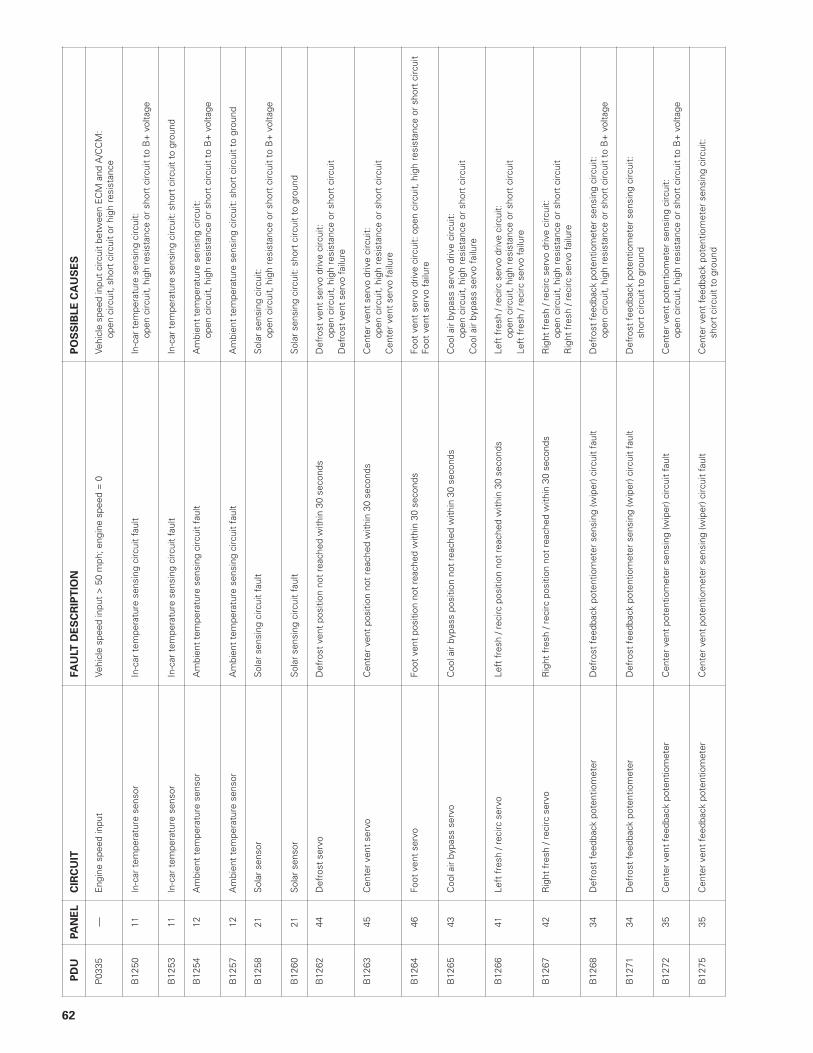
62
PD
UPA
NE
LC
IRC
UIT
FA
ULT
DE
SC
RIP
TIO
NP
OS
SIB
LE
CA
US
ES
P03
35—
Eng
ine
spee
d in
put
Vehi
cle
spee
d in
put
> 5
0 m
ph; e
ngin
e sp
eed
= 0
Vehi
cle
spee
d in
put
circ
uit
betw
een
EC
M a
nd A
/CC
M:
open
circ
uit,
sho
rt c
ircui
t or
hig
h re
sist
ance
B12
5011
In-c
ar t
empe
ratu
re s
enso
rIn
-car
tem
pera
ture
sen
sing
circ
uit
faul
tIn
-car
tem
pera
ture
sen
sing
circ
uit:
open
circ
uit,
hig
h re
sist
ance
or
shor
t ci
rcui
t to
B+
vol
tage
B12
5311
In-c
ar t
empe
ratu
re s
enso
rIn
-car
tem
pera
ture
sen
sing
circ
uit
faul
tIn
-car
tem
pera
ture
sen
sing
circ
uit:
sho
rt c
ircui
t to
gro
und
B12
5412
Am
bien
t te
mpe
ratu
re s
enso
rA
mbi
ent
tem
pera
ture
sen
sing
circ
uit
faul
tA
mbi
ent
tem
pera
ture
sen
sing
circ
uit:
open
circ
uit,
hig
h re
sist
ance
or
shor
t ci
rcui
t to
B+
vol
tage
B12
5712
Am
bien
t te
mpe
ratu
re s
enso
rA
mbi
ent
tem
pera
ture
sen
sing
circ
uit
faul
tA
mbi
ent
tem
pera
ture
sen
sing
circ
uit:
sho
rt c
ircui
t to
gro
und
B12
5821
Sol
ar s
enso
rS
olar
sen
sing
circ
uit
faul
tS
olar
sen
sing
circ
uit:
open
circ
uit,
hig
h re
sist
ance
or
shor
t ci
rcui
t to
B+
vol
tage
B12
6021
Sol
ar s
enso
rS
olar
sen
sing
circ
uit
faul
tS
olar
sen
sing
circ
uit:
sho
rt c
ircui
t to
gro
und
B12
6244
Def
rost
ser
voD
efro
st v
ent
posi
tion
not
reac
hed
with
in 3
0 se
cond
sD
efro
st v
ent
serv
o dr
ive
circ
uit:
open
circ
uit,
hig
h re
sist
ance
or
shor
t ci
rcui
tD
efro
st v
ent
serv
o fa
ilure
B12
6345
Cen
ter
vent
ser
voC
ente
r ve
nt p
ositi
on n
ot r
each
ed w
ithin
30
seco
nds
Cen
ter
vent
ser
vo d
rive
circ
uit:
open
circ
uit,
hig
h re
sist
ance
or
shor
t ci
rcui
tC
ente
r ve
nt s
ervo
fai
lure
B12
6446
Foot
ven
t se
rvo
Foot
ven
t po
sitio
n no
t re
ache
d w
ithin
30
seco
nds
Foot
ven
t se
rvo
driv
e ci
rcui
t: o
pen
circ
uit,
hig
h re
sist
ance
or
shor
t ci
rcui
tFo
ot v
ent
serv
o fa
ilure
B12
6543
Coo
l air
bypa
ss s
ervo
Coo
l air
bypa
ss p
ositi
on n
ot r
each
ed w
ithin
30
seco
nds
Coo
l air
bypa
ss s
ervo
driv
e ci
rcui
t:op
en c
ircui
t, h
igh
resi
stan
ce o
r sh
ort
circ
uit
Coo
l air
bypa
ss s
ervo
fai
lure
B12
6641
Left
fre
sh /
reci
rc s
ervo
Left
fre
sh /
reci
rc p
ositi
on n
ot r
each
ed w
ithin
30
seco
nds
Left
fre
sh /
reci
rc s
ervo
driv
e ci
rcui
t:op
en c
ircui
t, h
igh
resi
stan
ce o
r sh
ort
circ
uit
Left
fre
sh /
reci
rc s
ervo
fai
lure
B12
6742
Rig
ht f
resh
/ re
circ
ser
voR
ight
fre
sh /
reci
rc p
ositi
on n
ot r
each
ed w
ithin
30
seco
nds
Rig
ht f
resh
/ re
circ
ser
vo d
rive
circ
uit:
open
circ
uit,
hig
h re
sist
ance
or
shor
t ci
rcui
tR
ight
fre
sh /
reci
rc s
ervo
fai
lure
B12
6834
Def
rost
fee
dbac
k po
tent
iom
eter
Def
rost
fee
dbac
k po
tent
iom
eter
sen
sing
(wip
er) c
ircui
t fa
ult
Def
rost
fee
dbac
k po
tent
iom
eter
sen
sing
circ
uit:
open
circ
uit,
hig
h re
sist
ance
or
shor
t ci
rcui
t to
B+
vol
tage
B12
7134
Def
rost
fee
dbac
k po
tent
iom
eter
Def
rost
fee
dbac
k po
tent
iom
eter
sen
sing
(wip
er) c
ircui
t fa
ult
Def
rost
fee
dbac
k po
tent
iom
eter
sen
sing
circ
uit:
shor
t ci
rcui
t to
gro
und
B12
7235
Cen
ter
vent
fee
dbac
k po
tent
iom
eter
Cen
ter
vent
pot
entio
met
er s
ensi
ng (w
iper
) circ
uit
faul
tC
ente
r ve
nt p
oten
tiom
eter
sen
sing
circ
uit:
open
circ
uit,
hig
h re
sist
ance
or
shor
t ci
rcui
t to
B+
vol
tage
B12
7535
Cen
ter
vent
fee
dbac
k po
tent
iom
eter
Cen
ter
vent
pot
entio
met
er s
ensi
ng (w
iper
) circ
uit
faul
tC
ente
r ve
nt f
eedb
ack
pote
ntio
met
er s
ensi
ng c
ircui
t:sh
ort
circ
uit
to g
roun
d

63
PD
UPA
NE
LC
IRC
UIT
FA
ULT
DE
SC
RIP
TIO
NP
OS
SIB
LE
CA
US
ES
B12
7636
Foot
ven
t fe
edba
ck p
oten
tiom
eter
Foot
ven
t po
tent
iom
eter
sen
sing
(wip
er) c
ircui
t fa
ult
Foot
ven
t po
tent
iom
eter
sen
sing
circ
uit:
open
circ
uit,
hig
h re
sist
ance
or
shor
t ci
rcui
t to
B+
vol
tage
B12
7936
Foot
ven
t fe
edba
ck p
oten
tiom
eter
Foot
ven
t po
tent
iom
eter
sen
sing
(wip
er) c
ircui
t fa
ult
Foot
ven
t po
tent
iom
eter
sen
sing
circ
uit:
sho
rt c
ircui
t to
gro
und
B12
8033
Coo
l air
bypa
ss f
eedb
ack
pote
ntio
met
erC
ool a
ir by
pass
pot
entio
met
er s
ensi
ng (w
iper
) circ
uit
faul
tC
ool a
ir by
pass
pot
entio
met
er s
ensi
ng c
ircui
t:op
en c
ircui
t, h
igh
resi
stan
ce o
r sh
ort
circ
uit
to B
+ v
olta
ge
B12
8333
Coo
l air
bypa
ss f
eedb
ack
pote
ntio
met
erC
ool a
ir by
pass
pot
entio
met
er s
ensi
ng (w
iper
) circ
uit
faul
tC
ool a
ir by
pass
pot
entio
met
er s
ensi
ng c
ircui
t: s
hort
circ
uit
to g
roun
d
B12
8431
Left
fre
sh /
reci
rc f
eedb
ack
pote
ntio
met
erLe
ft f
resh
/ re
circ
pot
entio
met
er s
ensi
ng (w
iper
) circ
uit
faul
tLe
ft f
resh
/ re
circ
pot
entio
met
er s
ensi
ng c
ircui
t:op
en c
ircui
t, h
igh
resi
stan
ce o
r sh
ort
circ
uit
to B
+ v
olta
ge
B12
8731
Left
fre
sh /
reci
rc f
eedb
ack
pote
ntio
met
erLe
ft f
resh
/ re
circ
pot
entio
met
er s
ensi
ng (w
iper
) circ
uit
faul
tLe
ft f
resh
/ re
circ
pot
entio
met
er s
ensi
ng c
ircui
t: s
hort
circ
uit
to g
roun
d
B12
8832
Rig
ht f
resh
/ re
circ
fee
dbac
k po
tent
iom
eter
Rig
ht f
resh
/ re
circ
pot
entio
met
er s
ensi
ng (w
iper
) circ
uit
faul
tR
ight
fre
sh /
reci
rc p
oten
tiom
eter
sen
sing
circ
uit:
open
circ
uit,
hig
h re
sist
ance
or
shor
t ci
rcui
t to
B+
vol
tage
B12
9132
Rig
ht f
resh
/ re
circ
fee
dbac
k po
tent
iom
eter
Rig
ht f
resh
/ re
circ
pot
entio
met
er s
ensi
ng (w
iper
) circ
uit
faul
tR
ight
fre
sh /
reci
rc p
oten
tiom
eter
sen
sing
circ
uit:
sho
rt c
ircui
t to
gro
und
B12
92—
B+
pow
er s
uppl
y (v
ia A
/C Is
olat
e re
lay)
B+
pow
er s
uppl
y ci
rcui
t fa
ult
betw
een
B+
circ
uit
betw
een
A/C
Isol
ate
rela
y an
d A
/CC
M:
A/C
Isol
ate
rela
y an
d A
/CC
Mop
en c
ircui
t or
hig
h re
sist
ance
B12
94—
B+
pow
er s
uppl
y (v
ia A
/C Is
olat
e re
lay)
B+
pow
er s
uppl
y ci
rcui
t fa
ult
betw
een
B+
circ
uit
betw
een
A/C
Isol
ate
rela
y an
d A
/CC
M:
A/C
Isol
ate
rela
y an
d A
/CC
Msh
ort
circ
uit
to g
roun
d
B12
97—
Sen
sor
5 vo
lt re
fere
nce
volta
geS
enso
r 5
volt
refe
renc
e vo
ltage
circ
uit
faul
tS
enso
r 5
volt
refe
renc
e vo
ltage
circ
uit:
open
circ
uit
or s
hort
circ
uit
to B
+ v
olta
ge
B12
98—
Sen
sor
5 vo
lt re
fere
nce
volta
geS
enso
r 5
volt
refe
renc
e vo
ltage
circ
uit
faul
tS
enso
r 5
volt
refe
renc
e vo
ltage
circ
uit:
sho
rt c
ircui
t to
gro
und
B12
99—
Sen
sor
5 vo
lt re
fere
nce
volta
geS
enso
r 5
volt
refe
renc
e vo
ltage
circ
uit
faul
tS
enso
r 5
volt
refe
renc
e vo
ltage
circ
uit:
hig
h re
sist
ance
B13
55—
B+
pow
er s
uppl
yB
+ p
ower
sup
ply
circ
uit
faul
tB
+ p
ower
sup
ply
circ
uit:
ope
n ci
rcui
t or
sho
rt c
ircui
t to
gro
und
B18
4924
Face
ven
t di
ffer
entia
l tem
pera
ture
con
trol
Face
ven
t di
ffer
entia
l tem
pera
ture
con
trol
Face
ven
t di
ffer
entia
l tem
pera
ture
pot
entio
met
er c
ircui
t:po
tent
iom
eter
circ
uit
faul
top
en c
ircui
t, h
igh
resi
stan
ce o
r sh
ort
circ
uit
to B
+ v
olta
ge
B18
5224
Face
ven
t di
ffer
entia
l tem
pera
ture
con
trol
Face
ven
t di
ffer
entia
l tem
pera
ture
con
trol
Face
ven
t di
ffer
entia
l tem
pera
ture
pot
entio
met
er c
ircui
t:po
tent
iom
eter
circ
uit
faul
tsh
ort
circ
uit
to g
roun
d
B18
53—
Asp
irato
r m
otor
Asp
irato
r m
otor
circ
uit
faul
tA
spira
tor
mot
or c
ircui
t:op
en c
ircui
t or
hig
h re
sist
ance
Asp
irato
r m
otor
fai
lure
B18
56—
Asp
irato
r m
otor
Asp
irato
r m
otor
circ
uit
faul
tA
spira
tor
mot
or c
ircui
t sh
ort
circ
uit
to g
roun
d
B18
57—
Igni
tion
switc
hed
(Pos
I, A
ux) g
roun
d si
gnal
Igni
tion
switc
hed
grou
nd s
igna
l circ
uit
faul
tIg
nitio
n sw
itche
d gr
ound
sig
nal c
ircui
t op
en c
ircui
t or
hig
h re
sist
ance
B18
5823
Ref
riger
ant
dual
pre
ssur
e sw
itch
Ref
riger
ant
dual
pre
ssur
e sw
itch
circ
uit
faul
tR
efrig
eran
t ch
arge
low
Ref
riger
ant
dual
pre
ssur
e sw
itch
circ
uit:
open
circ
uit,
hig
h re
sist
ance
or
shor
t ci
rcui
t to
B+
vol
tage
Hig
h en
gine
tem
pera
ture
in h
igh
ambi
ent
tem
pera
ture
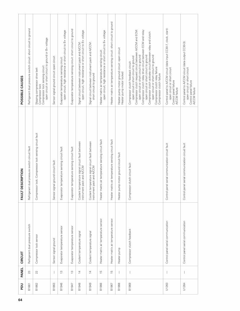
64
PD
UPA
NE
LC
IRC
UIT
FA
ULT
DE
SC
RIP
TIO
NP
OS
SIB
LE
CA
US
ES
B18
6123
Ref
riger
ant
dual
pre
ssur
e sw
itch
Ref
riger
ant
dual
pre
ssur
e sw
itch
circ
uit
faul
tR
efrig
eran
t du
al p
ress
ure
switc
h ci
rcui
t: s
hort
circ
uit
to g
roun
d
B18
6222
Com
pres
sor
lock
sen
sor
Com
pres
sor
lock
; Com
pres
sor
lock
sen
sing
circ
uit
faul
tS
lippi
ng c
ompr
esso
r dr
ive
belt
Com
pres
sor
lock
Com
pres
sor
lock
sen
sing
circ
uit:
open
circ
uit
or s
hort
circ
uit
to g
roun
d or
B+
vol
tage
B18
63—
Sen
sor
sign
al g
roun
dS
enso
r si
gnal
gro
und
circ
uit
faul
tS
enso
r si
gnal
gro
und
circ
uit
open
circ
uit
B19
4613
Eva
pora
tor
tem
pera
ture
sen
sor
Eva
pora
tor
tem
pera
ture
sen
sing
circ
uit
faul
tE
vapo
rato
r te
mpe
ratu
re s
ensi
ng c
ircui
t:op
en c
ircui
t, h
igh
resi
stan
ce o
r sh
ort
circ
uit
to B
+ v
olta
ge
B19
4713
Eva
pora
tor
tem
pera
ture
sen
sor
Eva
pora
tor
tem
pera
ture
sen
sing
circ
uit
faul
tE
vapo
rato
r te
mpe
ratu
re s
ensi
ng c
ircui
t: s
hort
circ
uit
to g
roun
d
B19
4814
Coo
lant
tem
pera
ture
sig
nal
Coo
lant
tem
pera
ture
sig
nal c
ircui
t fa
ult
betw
een
Sig
nal c
ircui
t be
twee
n in
stru
men
t pa
ck a
nd A
/CC
M:
inst
rum
ent
pack
and
A/C
CM
open
circ
uit,
hig
h re
sist
ance
or
shor
t ci
rcui
t to
B+
vol
tage
B19
4914
Coo
lant
tem
pera
ture
sig
nal
Coo
lant
tem
pera
ture
sig
nal c
ircui
t fa
ult
betw
een
Sig
nal c
ircui
t be
twee
n in
stru
men
t pa
ck a
nd A
/CC
M:
inst
rum
ent
pack
and
A/C
CM
shor
t ci
rcui
t to
gro
und
B19
6615
Hea
ter
mat
rix a
ir te
mpe
ratu
re s
enso
rH
eate
r m
atrix
air
tem
pera
ture
sen
sing
circ
uit
faul
tH
eate
r m
atrix
air
tem
pera
ture
sen
sing
circ
uit:
open
circ
uit,
hig
h re
sist
ance
or
shor
t ci
rcui
t to
B+
vol
tage
B19
6715
Hea
ter
mat
rix a
ir te
mpe
ratu
re s
enso
rH
eate
r m
atrix
air
tem
pera
ture
sen
sing
circ
uit
faul
tH
eate
r m
atrix
air
tem
pera
ture
sen
sing
circ
uit:
sho
rt c
ircui
t to
gro
und
B19
68—
Hea
ter
pum
pH
eate
r pu
mp
mot
or g
roun
d ci
rcui
t fa
ult
Hea
ter
pum
p m
otor
gro
und
circ
uit:
ope
n ci
rcui
tH
eate
r pu
mp
mot
or lo
cked
B19
69—
Com
pres
sor
clut
ch f
eedb
ack
Com
pres
sor
clut
ch c
ircui
t fa
ult
Com
pres
sor
clut
ch f
eedb
ack
circ
uit:
open
circ
uit
o sh
ort
circ
uit
to g
roun
dC
ompr
esso
r cl
utch
req
uest
circ
uit
betw
een
A/C
CM
and
EC
M:
open
circ
uit
or s
hort
circ
uit
to g
roun
dC
ompr
esso
r cl
utch
rel
ay d
rive
circ
uit
betw
een
EC
M a
nd r
elay
:op
en c
ircui
t or
sho
rt c
ircui
t to
gro
und
Com
pres
sor
clut
ch a
ctiv
ate
circ
uit
betw
een
rela
y an
d cl
utch
:op
en c
ircui
t or
sho
rt c
ircui
t to
gro
und
Com
pres
sor
clut
ch r
elay
fai
lure
Com
pres
sor
clut
ch f
ailu
re
U12
63—
Con
trol
pan
el s
eria
l com
mun
icat
ion
Con
trol
pan
el s
eria
l com
mun
icat
ion
circ
uit
faul
tC
ontr
ol p
anel
to
A/C
CM
circ
uit
(dat
a in
put
CC
30-7
, clo
ck, s
tart
):op
en c
ircui
t or
sho
rt c
ircui
tC
ontr
ol p
anel
fai
lure
A/C
CM
fai
lure
U12
64—
Con
trol
pan
el s
eria
l com
mun
icat
ion
Con
trol
pan
el s
eria
l com
mun
icat
ion
circ
uit
faul
tC
ontr
ol p
anel
to
A/C
CM
circ
uit
(dat
a ou
tput
CC
30-3
):op
en c
ircui
t or
sho
rt c
ircui
tC
ontr
ol p
anel
fai
lure
A/C
CM
fai
lure