CLIF MOCK™ CD-20A Sample Probe Controller User Manual
16
CLIF MOCK™ CD-20A Sample Probe Controller User Manual Manual No. 2350753-01, Rev. 02 Class I Groups C and D Hazardous Locations
Transcript of CLIF MOCK™ CD-20A Sample Probe Controller User Manual
CLIF MOCK™
CD-20A Sample Probe Controller User Manual
Manual No. 2350753-01, Rev. 02
Class I Groups C and D Hazardous Locations
Important Safety InformationSymbols and Terms Used in this Manual
! WARNING: This symbol identifies information about practices or circumstances that can lead to per-sonal injury or death, property damage, or economic loss.
CAUTION: Indicates actions or procedures which if not performed correctly may lead to personal injury or incorrect function of the instrument or connected equipment.
Important: Indicates actions or procedures which may affect instrument operation or may lead to an instrument response which is not planned.
Technical Support Contact Information
CameronMeasurement Systems Division14450 John F. Kennedy Blvd.Houston, TX 77032Phone: 1-800-654-3760; 281-582-9500Fax: 281-582-9599
Clif Mock is a trademark of Cameron International Corporation (“Cameron”).
© 2013 Cameron International Corporation (“Cameron”). All information contained in this publication is confidential and proprietary property of Cameron. Any reproduction or use of these instructions, drawings, or photographs without the express written permission of an officer of Cameron is forbidden.
All Rights Reserved.Printed in the United States of America.
Manual No. 2350753-01, Rev. 02 September 2013
iii
CD-20A Sample Probe Controller
Contents
Important Safety Information ............................................................................................................................... iiSection 1—Overview .......................................................................................................................................... 5
How It Works ................................................................................................................................................ 6Pulse Input Scaling ...................................................................................................................................... 6Table 1.1—Pulse Input Switch Setting Examples ........................................................................................ 6Repeat Time Scaling .................................................................................................................................... 7Table 1.2—Repeat Time Switch Setting Examples ...................................................................................... 7Hazardous Location Safety Compliance ...................................................................................................... 7Table 1.3—CD-20A Specifications ............................................................................................................... 7
Section 2—Installation and Wiring...................................................................................................................... 8Section 3—Maintenance .................................................................................................................................... 9
Operational Test ........................................................................................................................................... 9Repeat Mode (Time-Proportional) Check-Out ........................................................................................... 10External Pulse Mode (Flow-Proportional) Check-Out ................................................................................ 10Sample Probe and CD-20A Check-Out ..................................................................................................... 10Motor Control Assembly ..............................................................................................................................11Table 3.1—Troubleshooting Tips for 12VDC/24VDC Controllers .............................................................. 12Table 3.2—Troubleshooting Tips for 115VAC/230VAC Controllers ............................................................ 13Factory Repairs .......................................................................................................................................... 14

iv
Table of Contents CD-20A Sample Probe Controller
5
CD-20A Sample Probe Controller
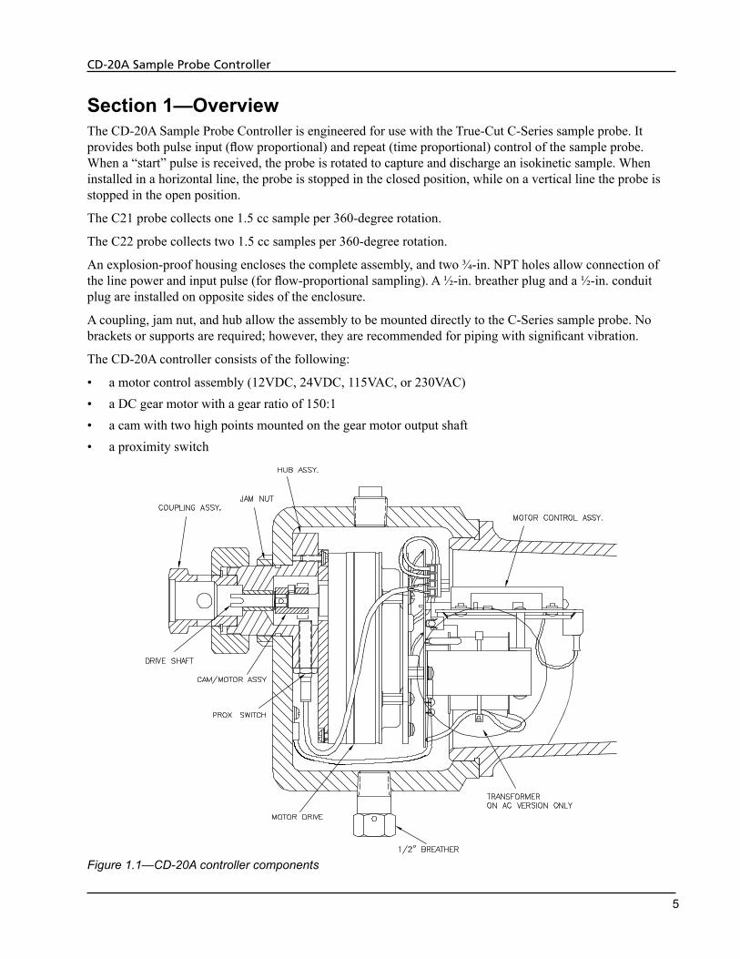
Section 1—OverviewThe CD-20A Sample Probe Controller is engineered for use with the True-Cut C-Series sample probe. It provides both pulse input (flow proportional) and repeat (time proportional) control of the sample probe. When a “start” pulse is received, the probe is rotated to capture and discharge an isokinetic sample. When installed in a horizontal line, the probe is stopped in the closed position, while on a vertical line the probe is stopped in the open position.
The C21 probe collects one 1.5 cc sample per 360-degree rotation.
The C22 probe collects two 1.5 cc samples per 360-degree rotation.
An explosion-proof housing encloses the complete assembly, and two ¾-in. NPT holes allow connection of the line power and input pulse (for flow-proportional sampling). A ½-in. breather plug and a ½-in. conduit plug are installed on opposite sides of the enclosure.
A coupling, jam nut, and hub allow the assembly to be mounted directly to the C-Series sample probe. No brackets or supports are required; however, they are recommended for piping with significant vibration.
The CD-20A controller consists of the following:
• a motor control assembly (12VDC, 24VDC, 115VAC, or 230VAC) • a DC gear motor with a gear ratio of 150:1• a cam with two high points mounted on the gear motor output shaft• a proximity switch
Figure 1.1—CD-20A controller components
6
CD-20A Sample Probe Controller
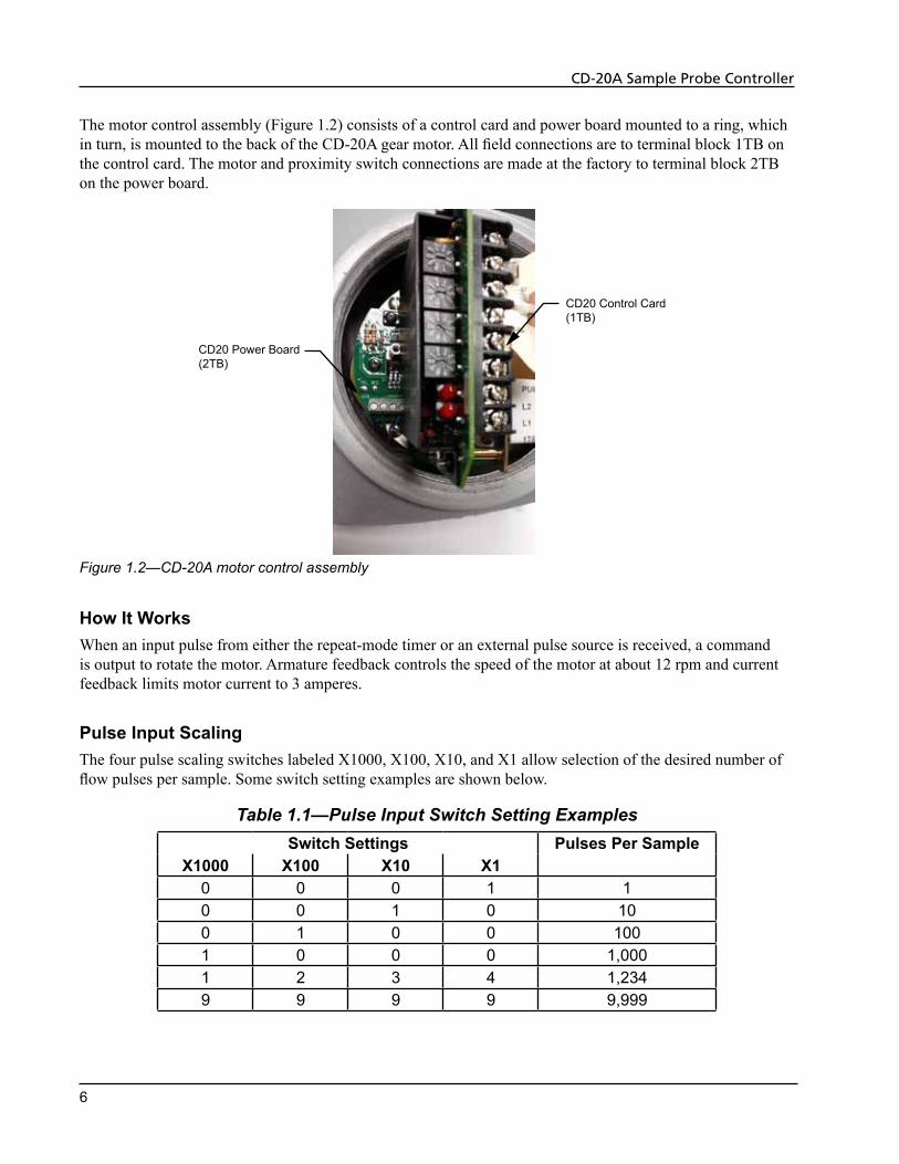
The motor control assembly (Figure 1.2) consists of a control card and power board mounted to a ring, which in turn, is mounted to the back of the CD-20A gear motor. All field connections are to terminal block 1TB on the control card. The motor and proximity switch connections are made at the factory to terminal block 2TB on the power board.
CD20 Power Board(2TB)
CD20 Control Card(1TB)
Figure 1.2—CD-20A motor control assembly
How It WorksWhen an input pulse from either the repeat-mode timer or an external pulse source is received, a command is output to rotate the motor. Armature feedback controls the speed of the motor at about 12 rpm and current feedback limits motor current to 3 amperes.
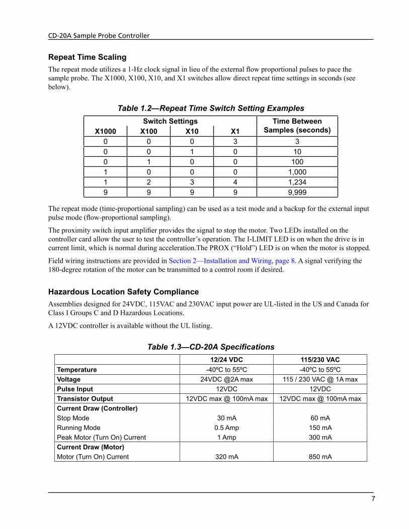
Pulse Input ScalingThe four pulse scaling switches labeled X1000, X100, X10, and X1 allow selection of the desired number of flow pulses per sample. Some switch setting examples are shown below.
Table 1.1—Pulse Input Switch Setting ExamplesSwitch Settings Pulses Per Sample
X1000 X100 X10 X10 0 0 1 10 0 1 0 100 1 0 0 1001 0 0 0 1,0001 2 3 4 1,2349 9 9 9 9,999
7
CD-20A Sample Probe Controller
Repeat Time ScalingThe repeat mode utilizes a 1-Hz clock signal in lieu of the external flow proportional pulses to pace the sample probe. The X1000, X100, X10, and X1 switches allow direct repeat time settings in seconds (see below).
Table 1.2—Repeat Time Switch Setting ExamplesSwitch Settings Time Between
Samples (seconds)X1000 X100 X10 X10 0 0 3 30 0 1 0 100 1 0 0 1001 0 0 0 1,0001 2 3 4 1,2349 9 9 9 9,999
The repeat mode (time-proportional sampling) can be used as a test mode and a backup for the external input pulse mode (flow-proportional sampling).
The proximity switch input amplifier provides the signal to stop the motor. Two LEDs installed on the controller card allow the user to test the controller’s operation. The I-LIMIT LED is on when the drive is in current limit, which is normal during acceleration.The PROX (“Hold”) LED is on when the motor is stopped.
Field wiring instructions are provided in Section 2—Installation and Wiring, page 8. A signal verifying the 180-degree rotation of the motor can be transmitted to a control room if desired.
Hazardous Location Safety ComplianceAssemblies designed for 24VDC, 115VAC and 230VAC input power are UL-listed in the US and Canada for Class I Groups C and D Hazardous Locations.
A 12VDC controller is available without the UL listing.
Table 1.3—CD-20A Specifications12/24 VDC 115/230 VAC
Temperature -40ºC to 55ºC -40ºC to 55ºCVoltage 24VDC @2A max 115 / 230 VAC @ 1A maxPulse Input 12VDC 12VDCTransistor Output 12VDC max @ 100mA max 12VDC max @ 100mA maxCurrent Draw (Controller)Stop Mode 30 mA 60 mARunning Mode 0.5 Amp 150 mAPeak Motor (Turn On) Current 1 Amp 300 mACurrent Draw (Motor)Motor (Turn On) Current 320 mA 850 mA
8
CD-20A Sample Probe Controller
Section 2—Installation and Wiring
! WARNING: This module is designed for connection to hazardous electric voltages. Ignoring this warning can result in severe personal injury or mechanical damage. This product must be reliably earthed and installed by qualified personnel in accordance with the prevailing local electrical wiring regulations and safety standards.
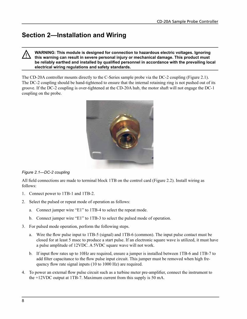
The CD-20A controller mounts directly to the C-Series sample probe via the DC-2 coupling (Figure 2.1). The DC-2 coupling should be hand-tightened to ensure that the internal retaining ring is not pushed out of its groove. If the DC-2 coupling is over-tightened at the CD-20A hub, the motor shaft will not engage the DC-1 coupling on the probe.
Figure 2.1—DC-2 coupling
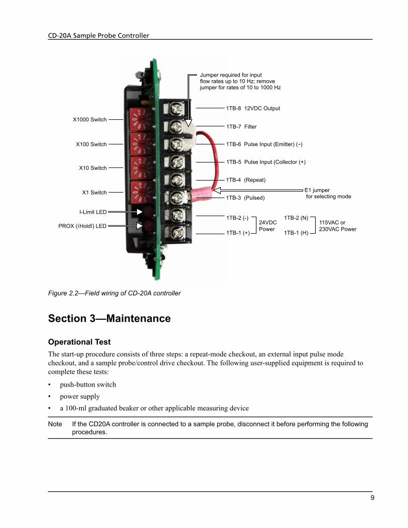
All field connections are made to terminal block 1TB on the control card (Figure 2.2). Install wiring as follows:
1. Connect power to 1TB-1 and 1TB-2.
2. Select the pulsed or repeat mode of operation as follows:
a. Connect jumper wire “E1” to 1TB-4 to select the repeat mode.
b. Connect jumper wire “E1” to 1TB-3 to select the pulsed mode of operation.
3. For pulsed mode operation, perform the following steps.
a. Wire the flow pulse input to 1TB-5 (signal) and 1TB-6 (common). The input pulse contact must be closed for at least 5 msec to produce a start pulse. If an electronic square wave is utilized, it must have a pulse amplitude of 12VDC. A 5VDC square wave will not work.
b. If input flow rates up to 10Hz are required, ensure a jumper is installed between 1TB-6 and 1TB-7 to add filter capacitance to the flow pulse input circuit. This jumper must be removed when high fre-quency flow rate signal inputs (10 to 1000 Hz) are required.
4. To power an external flow pulse circuit such as a turbine meter pre-amplifier, connect the instrument to the +12VDC output at 1TB-7. Maximum current from this supply is 50 mA.
9
CD-20A Sample Probe Controller
1TB-6 Pulse Input (Emitter) ( )-
1TB-5 Pulse Input (Collector (+)
1TB-4 (Repeat)
1TB-3 (Pulsed)
1TB-8 12VDC Output
1TB-7 Filter
Jumper required for input flow rates up to 10 Hz; removejumper for rates of 10 to 1000 Hz
E1 jumper for selecting mode
X1000 Switch
X100 Switch
X10 Switch
X1 Switch
I-Limit LED
PROX ( Holdî) LEDì1TB-2 (-)
1TB-1 (+)
24VDC Power
1TB-2 (N)
1TB-1 (H)
115VAC or230VAC Power
Figure 2.2—Field wiring of CD-20A controller
Section 3—Maintenance
Operational TestThe start-up procedure consists of three steps: a repeat-mode checkout, an external input pulse mode checkout, and a sample probe/control drive checkout. The following user-supplied equipment is required to complete these tests:
• push-button switch• power supply• a 100-ml graduated beaker or other applicable measuring device
Note If the CD20A controller is connected to a sample probe, disconnect it before performing the following procedures.
10
CD-20A Sample Probe Controller
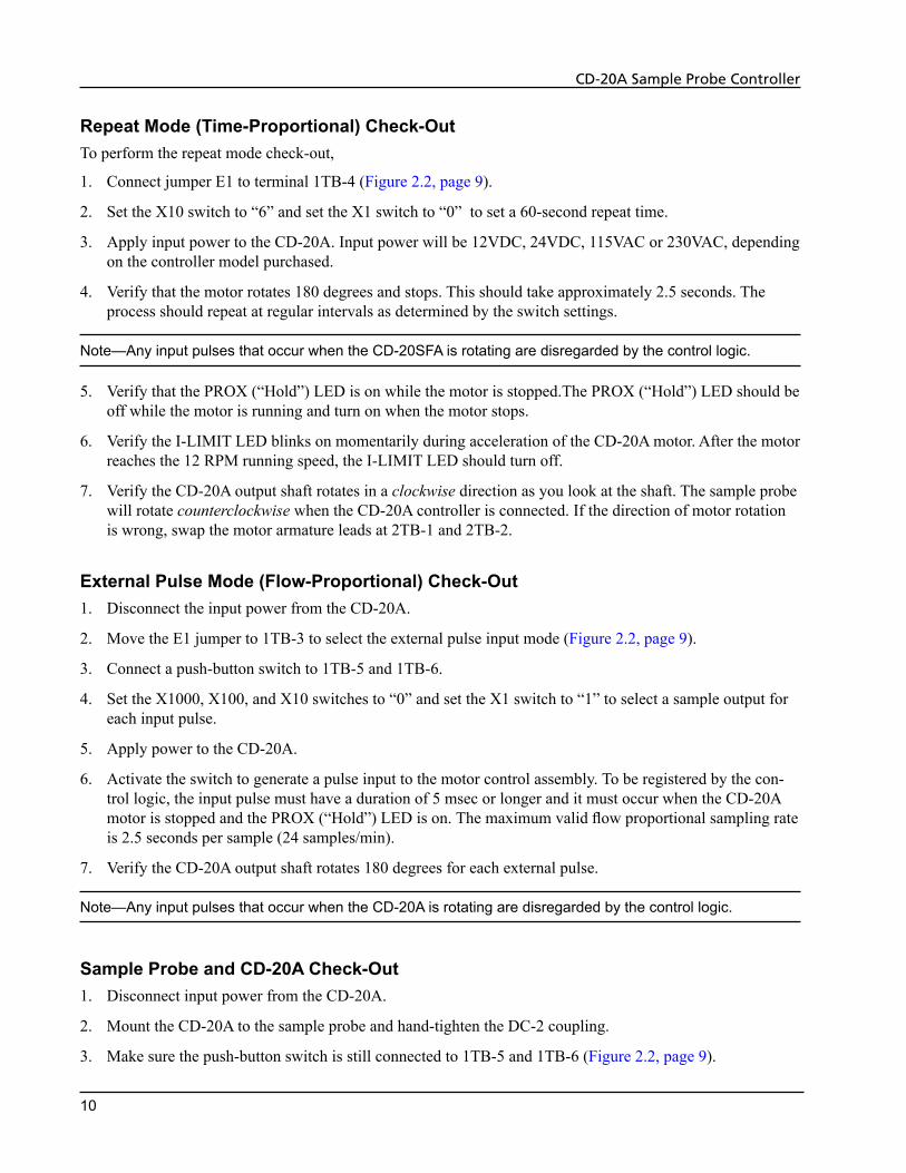
Repeat Mode (Time-Proportional) Check-OutTo perform the repeat mode check-out,
1. Connect jumper E1 to terminal 1TB-4 (Figure 2.2, page 9).
2. Set the X10 switch to “6” and set the X1 switch to “0” to set a 60-second repeat time.
3. Apply input power to the CD-20A. Input power will be 12VDC, 24VDC, 115VAC or 230VAC, depending on the controller model purchased.
4. Verify that the motor rotates 180 degrees and stops. This should take approximately 2.5 seconds. The process should repeat at regular intervals as determined by the switch settings.
Note—Any input pulses that occur when the CD-20SFA is rotating are disregarded by the control logic.
5. Verify that the PROX (“Hold”) LED is on while the motor is stopped.The PROX (“Hold”) LED should be off while the motor is running and turn on when the motor stops.
6. Verify the I-LIMIT LED blinks on momentarily during acceleration of the CD-20A motor. After the motor reaches the 12 RPM running speed, the I-LIMIT LED should turn off.
7. Verify the CD-20A output shaft rotates in a clockwise direction as you look at the shaft. The sample probe will rotate counterclockwise when the CD-20A controller is connected. If the direction of motor rotation is wrong, swap the motor armature leads at 2TB-1 and 2TB-2.
External Pulse Mode (Flow-Proportional) Check-Out1. Disconnect the input power from the CD-20A.
2. Move the E1 jumper to 1TB-3 to select the external pulse input mode (Figure 2.2, page 9).
3. Connect a push-button switch to 1TB-5 and 1TB-6.
4. Set the X1000, X100, and X10 switches to “0” and set the X1 switch to “1” to select a sample output for each input pulse.
5. Apply power to the CD-20A.
6. Activate the switch to generate a pulse input to the motor control assembly. To be registered by the con-trol logic, the input pulse must have a duration of 5 msec or longer and it must occur when the CD-20A motor is stopped and the PROX (“Hold”) LED is on. The maximum valid flow proportional sampling rate is 2.5 seconds per sample (24 samples/min).
7. Verify the CD-20A output shaft rotates 180 degrees for each external pulse.
Note—Any input pulses that occur when the CD-20A is rotating are disregarded by the control logic.
Sample Probe and CD-20A Check-Out1. Disconnect input power from the CD-20A.
2. Mount the CD-20A to the sample probe and hand-tighten the DC-2 coupling.
3. Make sure the push-button switch is still connected to 1TB-5 and 1TB-6 (Figure 2.2, page 9).
11
CD-20A Sample Probe Controller
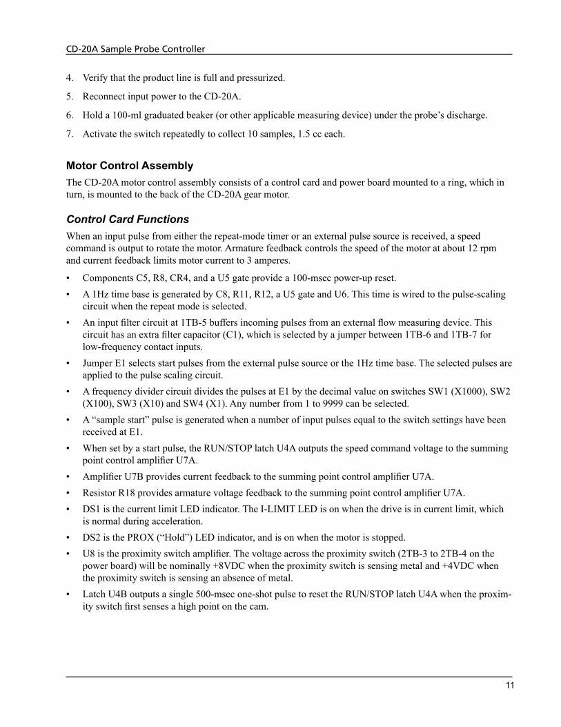
4. Verify that the product line is full and pressurized.
5. Reconnect input power to the CD-20A.
6. Hold a 100-ml graduated beaker (or other applicable measuring device) under the probe’s discharge.
7. Activate the switch repeatedly to collect 10 samples, 1.5 cc each.
Motor Control AssemblyThe CD-20A motor control assembly consists of a control card and power board mounted to a ring, which in turn, is mounted to the back of the CD-20A gear motor.
Control Card FunctionsWhen an input pulse from either the repeat-mode timer or an external pulse source is received, a speed command is output to rotate the motor. Armature feedback controls the speed of the motor at about 12 rpm and current feedback limits motor current to 3 amperes.
• Components C5, R8, CR4, and a U5 gate provide a 100-msec power-up reset.• A 1Hz time base is generated by C8, R11, R12, a U5 gate and U6. This time is wired to the pulse-scaling
circuit when the repeat mode is selected.• An input filter circuit at 1TB-5 buffers incoming pulses from an external flow measuring device. This
circuit has an extra filter capacitor (C1), which is selected by a jumper between 1TB-6 and 1TB-7 for low-frequency contact inputs.
• Jumper E1 selects start pulses from the external pulse source or the 1Hz time base. The selected pulses are applied to the pulse scaling circuit.
• A frequency divider circuit divides the pulses at E1 by the decimal value on switches SW1 (X1000), SW2 (X100), SW3 (X10) and SW4 (X1). Any number from 1 to 9999 can be selected.
• A “sample start” pulse is generated when a number of input pulses equal to the switch settings have been received at E1.
• When set by a start pulse, the RUN/STOP latch U4A outputs the speed command voltage to the summing point control amplifier U7A.
• Amplifier U7B provides current feedback to the summing point control amplifier U7A.• Resistor R18 provides armature voltage feedback to the summing point control amplifier U7A.• DS1 is the current limit LED indicator. The I-LIMIT LED is on when the drive is in current limit, which
is normal during acceleration.• DS2 is the PROX (“Hold”) LED indicator, and is on when the motor is stopped.• U8 is the proximity switch amplifier. The voltage across the proximity switch (2TB-3 to 2TB-4 on the
power board) will be nominally +8VDC when the proximity switch is sensing metal and +4VDC when the proximity switch is sensing an absence of metal.
• Latch U4B outputs a single 500-msec one-shot pulse to reset the RUN/STOP latch U4A when the proxim-ity switch first senses a high point on the cam.
12
CD-20A Sample Probe Controller
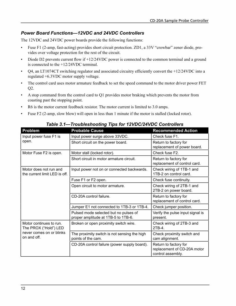
Power Board Functions—12VDC and 24VDC ControllersThe 12VDC and 24VDC power boards provide the following functions:
• Fuse F1 (2-amp, fast-acting) provides short circuit protection. ZD1, a 33V “crowbar” zener diode, pro-vides over voltage protection for the rest of the circuit.
• Diode D2 prevents current flow if +12/24VDC power is connected to the common terminal and a ground is connected to the +12/24VDC terminal.
• Q4, an LT1074CT switching regulator and associated circuitry efficiently convert the +12/24VDC into a regulated +6.3VDC motor supply voltage.
• The control card uses motor armature feedback to set the speed command to the motor driver power FET Q2.
• A stop command from the control card to Q1 provides motor braking which prevents the motor from coasting past the stopping point.
• R6 is the motor current feedback resistor. The motor current is limited to 3.0 amps.• Fuse F2 (2-amp, slow blow) will open in less than 1 minute if the motor is stalled (locked rotor).
Table 3.1—Troubleshooting Tips for 12VDC/24VDC Controllers Problem Probable Cause Recommended ActionInput power fuse F1 is open.
Input power surge above 33VDC. Check fuse F1.Short circuit on the power board. Return to factory for
replacement of power board.Motor Fuse F2 is open. Motor stall (locked rotor). Check fuse F2.
Short circuit in motor armature circuit. Return to factory for replacement of control card.
Motor does not run and the current limit LED is off.
Input power not on or connected backwards. Check wiring of 1TB-1 and 1TB-2 on control card.
Fuse F1 or F2 open. Check fuse continuity.Open circuit to motor armature. Check wiring of 2TB-1 and
2TB-2 on power board.CD-20A control failure. Return to factory for
replacement of control card.Jumper E1 not connected to 1TB-3 or 1TB-4. Check jumper position.Pulsed mode selected but no pulses of proper amplitude at 1TB-5 to 1TB-6.
Verify the pulse input signal is present.
Motor continues to run. The PROX (“Hold”) LED never comes on or blinks on and off.
Broken or open proximity switch wire. Check wiring of 2TB-3 and 2TB-4.
The proximity switch is not sensing the high points of the cam.
Check proximity switch and cam alignment.
CD-20A control failure (power supply board). Return to factory for replacement of CD-20A motor control assembly.
13
CD-20A Sample Probe Controller
Power Board Functions—115VAC and 230VAC ControllersThe CD-20A power board provides the following functions:
• Fuse F1 (1-amp, type AGC) provides short circuit protection. It will open if there is a short in the primary or secondary of transformer T1.
• For115VACunits, transformer T1 converts the input power to 14 VRMS secondary power when primary jumpers W1 and W2 are nstalled on the power board. Note:DonotconfusethesejumperswithW1andW2onthecontrolcard.
• For230VACunits, transformer T1 converts the input power to 14 VRMS secondary power when primary jumper W3 is installed on the power board.
• Diodes CR2, CR3, CR4, and CR5 provide full-wave rectified DC voltage for use in driving the motor.• Transistor circuits including Q1, Q2, and Q4 provide the basic speed control and drive for the CD-20A
gear motor, which has a 9VDC armature and pm field.• Power Fet Q3 is on when the RUN/STOP latch is commanding the motor to stop. Q3 provides electronic
braking of the motor to minimize coast past the desired probe stopping point.• Resistor R5 is the current-sensing resistor for the current limit switch.• Regulator U1 provides +12VDC for the control card.
Table 3.2—Troubleshooting Tips for 115VAC/230VAC ControllersProblem Probable Cause Recommended ActionInput power fuse F1 is open. Transformer T1 has an internal
secondary winding or primary winding short.
Return to factory for replacement of T1 or power board.
Rectifier diode CR2, CR3, CR4, or CR5 shorted.
Check diodes with an ohmmeter and return to factory for replacement of power board or CD-20A motor control.
Input power transformer jumper is installed incorrectly.
Check for jumper across power input (115VAC or 230VAC) to Neutral.
Current limit LED is on, the motor is stopped.
Sample probe jammed or the motor armature is driving the probe backwards (clockwise) against the cam drop off point.
To isolate the problem, power down and remove the CD-20A from the probe and verify CD-20A output shaft turns clockwise as you look at it in repeat mode. Verify sample probe can be turned counterclockwise with a screwdriver and proper discharge is obtained.
Short across A1 to A2 of CD-20A motor output due to a short in power FET Q3.
Power down, remove motor leads, and verify that when power is reapplied, the current limit light is off. Then check motor armature resistance to verify the short circuit. If motor circuit checks out, return to factory for replacement of CD-20A motor control assembly.
Bind-up in gear box. Return to factory for replacement of 150:1 ratio gear motor.
14
CD-20A Sample Probe Controller
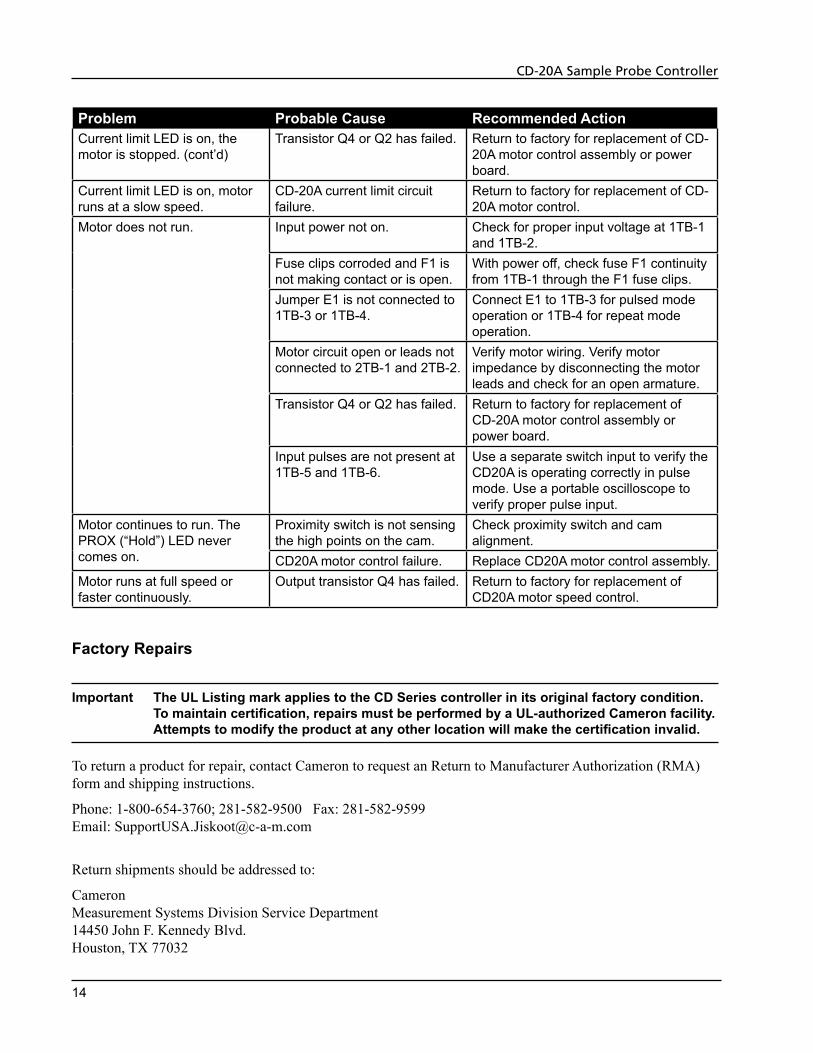
Problem Probable Cause Recommended ActionCurrent limit LED is on, the motor is stopped. (cont’d)
Transistor Q4 or Q2 has failed. Return to factory for replacement of CD-20A motor control assembly or power board.
Current limit LED is on, motor runs at a slow speed.
CD-20A current limit circuit failure.
Return to factory for replacement of CD-20A motor control.
Motor does not run. Input power not on. Check for proper input voltage at 1TB-1 and 1TB-2.
Fuse clips corroded and F1 is not making contact or is open.
With power off, check fuse F1 continuity from 1TB-1 through the F1 fuse clips.
Jumper E1 is not connected to 1TB-3 or 1TB-4.
Connect E1 to 1TB-3 for pulsed mode operation or 1TB-4 for repeat mode operation.
Motor circuit open or leads not connected to 2TB-1 and 2TB-2.
Verify motor wiring. Verify motor impedance by disconnecting the motor leads and check for an open armature.
Transistor Q4 or Q2 has failed. Return to factory for replacement of CD-20A motor control assembly or power board.
Input pulses are not present at 1TB-5 and 1TB-6.
Use a separate switch input to verify the CD20A is operating correctly in pulse mode. Use a portable oscilloscope to verify proper pulse input.
Motor continues to run. The PROX (“Hold”) LED never comes on.
Proximity switch is not sensing the high points on the cam.
Check proximity switch and cam alignment.
CD20A motor control failure. Replace CD20A motor control assembly.Motor runs at full speed or faster continuously.
Output transistor Q4 has failed. Return to factory for replacement of CD20A motor speed control.
Factory Repairs
Important The UL Listing mark applies to the CD Series controller in its original factory condition. To maintain certification, repairs must be performed by a UL-authorized Cameron facility. Attempts to modify the product at any other location will make the certification invalid.
To return a product for repair, contact Cameron to request an Return to Manufacturer Authorization (RMA) form and shipping instructions.
Phone: 1-800-654-3760; 281-582-9500 Fax: 281-582-9599 Email: [email protected]
Return shipments should be addressed to:
Cameron Measurement Systems Division Service Department 14450 John F. Kennedy Blvd. Houston, TX 77032
15
CD-20A Sample Probe Controller
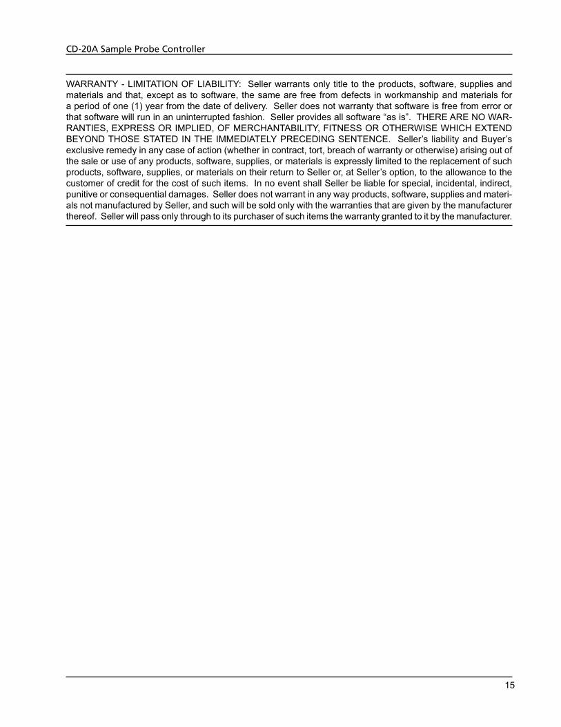
WARRANTY - LIMITATION OF LIABILITY: Seller warrants only title to the products, software, supplies and materials and that, except as to software, the same are free from defects in workmanship and materials for a period of one (1) year from the date of delivery. Seller does not warranty that software is free from error or that software will run in an uninterrupted fashion. Seller provides all software “as is”. THERE ARE NO WAR-RANTIES, EXPRESS OR IMPLIED, OF MERCHANTABILITY, FITNESS OR OTHERWISE WHICH EXTEND BEYOND THOSE STATED IN THE IMMEDIATELY PRECEDING SENTENCE. Seller’s liability and Buyer’s exclusive remedy in any case of action (whether in contract, tort, breach of warranty or otherwise) arising out of the sale or use of any products, software, supplies, or materials is expressly limited to the replacement of such products, software, supplies, or materials on their return to Seller or, at Seller’s option, to the allowance to the customer of credit for the cost of such items. In no event shall Seller be liable for special, incidental, indirect, punitive or consequential damages. Seller does not warrant in any way products, software, supplies and materi-als not manufactured by Seller, and such will be sold only with the warranties that are given by the manufacturer thereof. Seller will pass only through to its purchaser of such items the warranty granted to it by the manufacturer.

R U S S I A
+603.5569.0501ms-kl @ c-a-m.com


![The CLIF Consortium Acute Decompensation score (CLIF-C …diposit.ub.edu/dspace/bitstream/2445/125144/1/644976.pdf(ACLF) [1-3], which is diagnosed using the CLIF Consortium organ failure](https://static.fdocuments.in/doc/165x107/5e2367d96ea68e6f9a16fe5e/the-clif-consortium-acute-decompensation-score-clif-c-aclf-1-3-which-is-diagnosed.jpg)