
Click here to add Company Name and Date 2 Parker is the global leader in motion and control...
37
-
Upload
leon-markle -
Category
Documents
-
view
218 -
download
0
Transcript of Click here to add Company Name and Date 2 Parker is the global leader in motion and control...


Click here to addCompany Name
and Date

3
Parker is the global leader in
motion and control technologies,
partnering with its customers to increase
their productivity and profitability.

4
• 3rd Generation post-compensated valve• Target Launch – October 2006
Load-Sense Pressure Compensated Valve
with Flow-Sharing(Post-Compensated)

5
Specifications
• Flows– Pump input up to 60 GPM
– Work sections up to 50 GPM
• Pressure 5000 PSI• Sectional construction• Max. porting
– Inlet SAE 16 top and side
– Work SAE 12
– Outlet SAE 16 top and SAE 20 side

6
Model Logic
V = valveP = lspc (post-compensated)170 = max work section flow in LPM
Remember the VO40:V = valveO = open center40 = max work section flow in plum
7
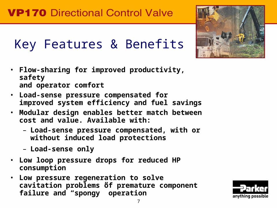
Key Features & Benefits
• Flow-sharing for improved productivity, safetyand operator comfort
• Load-sense pressure compensated for improved system efficiency and fuel savings
• Modular design enables better match between cost and value. Available with:– Load-sense pressure compensated, with or
without induced load protections
– Load-sense only
• Low loop pressure drops for reduced HP consumption
• Low pressure regeneration to solve cavitation problems of premature component failure and “spongy” operation
8
Key Market Drivers
• Improved machine controllability and productivity
• Horsepower utilization, due tier II and III engines
• Fuel cost

9
Target Markets
• Wheel loaders and dozers– Launched to Deere September 2004
for J Series Loaders
• Cranes• Forestry – loaders, feller-bunchers,
harvesters, forwarders, skidders• Refuse – side loaders• Snow and ice• Distribution

10
Competitors
• Post-Compensated– Danfoss – PVG100 (new)
– Husco – SX180 (new)
– Rexroth – SX14? (have not seen in dist’n channel)
– Rexroth - M4-15 (120 lpm out of work section)
• Pre-Compensated– MP18 and MP22 (being discontinued; Wooster closing)

11
Flow-Sharing
Adjusts to a pump over-demand conditions by reducing the flow to the selected functions, while maintaining the speed relationship between those functions
The benefit - the operator can maintain the control of the machine
The result - increased productivity, improved safety and operator comfort

12
Flow-Sharing Example #1
Max Pump Flow WS 1 WS 2 40 gpm 28 gpm 12 gpm
Scenario #1 - operator wants more speed from WS 1
WS 1 WS 2 Req PumpReq Flow Req Flow Flow
34 gpm 12 gpm 46 gpm
Overdemand = 40/46 = .87, so reduce flows by 13%
Max PumpActual WS Flow WS 1 WS 2 Flow.87 x 34 gpm for WS 1 29.6 gpm 10.4 gpm 40 gpm.87 x 12 gpm for WS 2

13
Flow-Sharing - Example #1 Full pump flow is 40 GPM, but
operator wants 46 GPM
Work sectionflows at full pump displacementof 40 GPM
28
12
34
12
29.6
10.4
0
5
10
15
20
25
30
35
GP
M
Operator wants 40 GPM from two work sections
But now operator wants 46 GPM
Only 40 GPM available, so valve goes into over-demand and divides the pump flow accordingly

14
Flow-Sharing - Example #2
Max Pump Flow WS 1 WS 2 40 gpm 28 gpm 12 gpm
Scenario #2 - engine rpm's decrease
Max Pump Flow30 gpm
Overdemand = 30/40 = .75, so reduce flows by 25%
Actual WS Flow WS 1 WS 2.75 x 28 gpm for WS 1 21 gpm 9 gpm.75 x 12 gpm for WS 2

15
Flow-Sharing - Example #2 Engine RPM decreases flow
from 40 GPM to 30 GPM
28
12
21
9
0
5
10
15
20
25
30
GP
M
Operator wants 40 GPM from two work sections
Engine rpm’s drop so max pump flow is 30 GPM; valve divides the flow accordingly
Work sectionflows at full pump displacementof 40 GPM
16
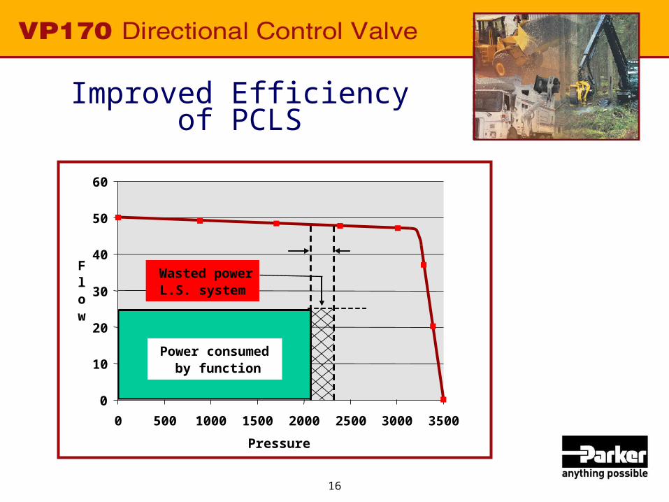
Improved Efficiencyof PCLS
0
10
20
30
40
50
60
0 500 1000 1500 2000 2500 3000 3500
Pressure
Flow
Power consumed by function
Wasted powerL.S. system
17
Improved Efficiencyof PCLS
“A big reason for the change by Deere was mounting fuel costs. The pressure compensated load-sensing variable displacement system is a lot more fuel efficient than the open-center system, depending on operation, by as much as 30, 40, or even 50% better,” says Anders Lindstrom, Senior Systems Engineer with Parker Hannifin.
“With the fuel savings I get on two of my 437Cs, I can make the payment on one.”

18
Modular Design Offers Three Circuit Options
Load sense ck for all circuit options located between the work ports!!!
Induced load/transition ck
Compensator
2. Load-sense pressure scompensated (PCLS) w/o induced load protection
Compensator
1. Load-sense pressure compensated (PCLS) with induced load protection

19
Modular Design Offers Three Circuit Options
3. Load-sense only
Transition ck
Load sense ck for all circuit options located between the work ports !!!

20
Circuit – PCLS with Induced Load Protection
Pressure compensated load-sense (PCLS)w/ reverse flow check

21
Circuit – PCLS without Induced Load Protection
Pressure compensated load-sense (PCLS)w/o reverse flow check

22
Circuit – LS only
Load-sense valve circuit

23
Low Loop Pressure DropPorts A/B - tank
Workport to Tank Delta P - Section #2
0
50
100
150
200
250
300
0 10 20 30 40 50 60 70 80 90
Flow (gpm)
Pre
ssu
re (
psi
)
0.0
5.0
10.0
15.0
20.0
0.0 50.0 100.0 150.0 200.0 250.0 300.0
Flow (lpm)
Pre
ssu
re (
bar
)
VG20 & V40
VG35
V42
VP170

24
Spool Options
• Types– 3 way cylinder and motor
– 4 way cylinder and motor
– 4 position float
• Flows – Flow limited at full stroke and 250 PSI margin
• GPM 8, 16, 24, 32, 45• Additional flow limitation can be achieved with spool
stroke limiters for ports A or B or both. Applies to hydraulic remote and solenoid operated.
– Not flow limited• Another spool available that falls off the notch at full
stroke and will try to output the full pump flow

25
Inlet Options

26
Inlet Options

27
Outlet Options

28
Low Pressure Regeneration
• Low pressure regeneration– Addresses cavitation
• Cavitation wreaks havoc on hydraulic components and results in spongymachine operation
• During valve operation, the valve will sense if a function is cavitating and will force oil across anti-cavitation checks to fill void
• If there is still a void in the hydraulic loop, when spools returned to neutral – will keep pump on stroke until a specified pressure level is achieved in the loop
29
Robust
• Endurance and fatigue testing:– Inlet, work sections and outlet fatigue tested
@ 6250 PSI and 3M cycles – NO FAILURES
– Load-sense checks endurance tested@ 5000 PSI and 2M cycles – NO FAILURES
– Transition/induced load check tested@ 5000 PSI and 1M cycles – NO FAILURES

30
Performance Enhancement
• Meter-out control can increase P-A/B pressure drop, when opposite port energized
• Work section body lengthened to ensure that pressure drop P/A-B not affected when meter-out control required
Port BTank

31
Performance Enhancement
• 4-position float work section – When work section is in the float
position, traditional design will draw oil A and B tank cores
• VP170 design can draw oil from:– Tank cores of ports A and B
– Return flow from port B• This improves float down time
and addresses potential cavitation

32
Additional Benefits
• Fly cut lands each critical area (10) means consistent metering from valve to valve
• Uses same spool positioners as VA20 and PC25 — reduces cost, risk and improves delivery
• Uses same port accessories as FIVE other valve series –– reduces cost, risk and improves delivery
• Spool stroke of .406" longest in industry — this means more metering vs. spool stroke
• One solenoid used for on/off and proportional applications

33
Summary
• Pressures to 5000 PSI• Flow range is 8-55 gpm out of the work port• Flow-sharing• Circuit options – load-sense pressure compensated or load-sense• Optional induced load protection • Optional low pressure regen and void filling scheme • Improved filling scheme during float position (4 position float work section)• Flexible, compact and cost effective EH package• Symmetrical spool for easy conversion to right or left-handed sections• Same spool positioners and port accessories as open-center
counterparts• Stroke limiters available for hydraulic remote
and solenoid operation• Full complement of flow-limited spools available• Easily serviceable — all checks located on top
of work section

34
VP170 Product Launch
• Literature– Product Catalog HY14-2006/US
– Overview Bulletin HY14-2006/US
– Service Bulletin HY14-2006-M1/US
– Catalog CD HY14-2006/US
– Advertisement
– Product Bit
– News Release
– To order call 1-800-CPARKER

35
• http://www.parker.com/hydraulicvalve– Complete product information
– Applications
– Systems and subsystems
Hydraulic Valve SolutionsFor Mobile & Truck Applications
36
Contact Us• Phone: 440-366-5200• Fax: 440-366-5253• Local Parker Distributor
www.parker.com/hydraulicvalve
37
Thank You!
Parker, your singlesource for all your
Hydraulic ValveSolutions.