CLIC MDI stabilization update A.Jeremie G.Balik, B.Bolzon, L.Brunetti, G.Deleglise A.Badel, B.Caron,...
23
CLIC MDI stabilization update A.Jeremie G.Balik, B.Bolzon, L.Brunetti, G.Deleglise A.Badel, B.Caron, R.Lebreton, J.Lottin Together with colleagues from the CLIC stabilisation WG and CLIC MDI WG IWLC2010 International Workshop on Linear Colliders 2010
-
Upload
molly-evans -
Category
Documents
-
view
213 -
download
0
Transcript of CLIC MDI stabilization update A.Jeremie G.Balik, B.Bolzon, L.Brunetti, G.Deleglise A.Badel, B.Caron,...

CLIC MDI stabilization update
A.JeremieG.Balik, B.Bolzon, L.Brunetti, G.Deleglise
A.Badel, B.Caron, R.Lebreton, J.LottinTogether with colleagues from the CLIC stabilisation WG and CLIC MDI WG
IWLC2010 International Workshop on Linear Colliders 2010
Some commentsSeveral PhDs:
– C.Montag (DESY) 1997 – S.Redaelli (CERN) 2003– B.Bolzon (LAPP) 2007– M.Warden (Oxford) 2010– R. LeBreton (SYMME) ~2012
Tolerances Main beam Quadrupoles
Final Focusing Quadrupoles
Vertical 1 nm > 1 Hz 0.1 nm > 4 Hz
Horizontal 5 nm > 1 Hz 5 nm > 4 Hz
• There is no completely validated stabilization system (off the shelf) available yet…
• There are proofs of principle available.
Initially, only vertical direction was studied
2IWLC2010 Geneva 2010 A.Jeremie
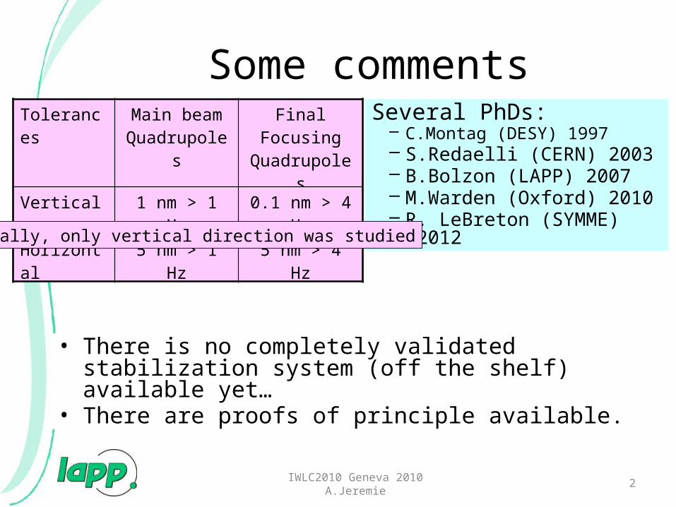
Example of spectral analysis of different disturbance sources
Acoustic disturbance :
Amplified by the structure itself : the eigenfrequencies
Ground motion :
Seismic motion
Cultural noise
A pink noise on a large bandwidth
2 different mechanical functions:• Isolate• Compensate the resonances
3IWLC2010 Geneva 2010 A.Jeremie
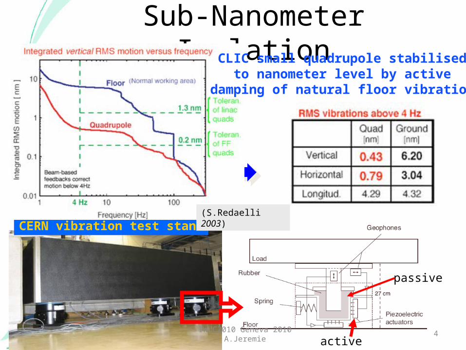
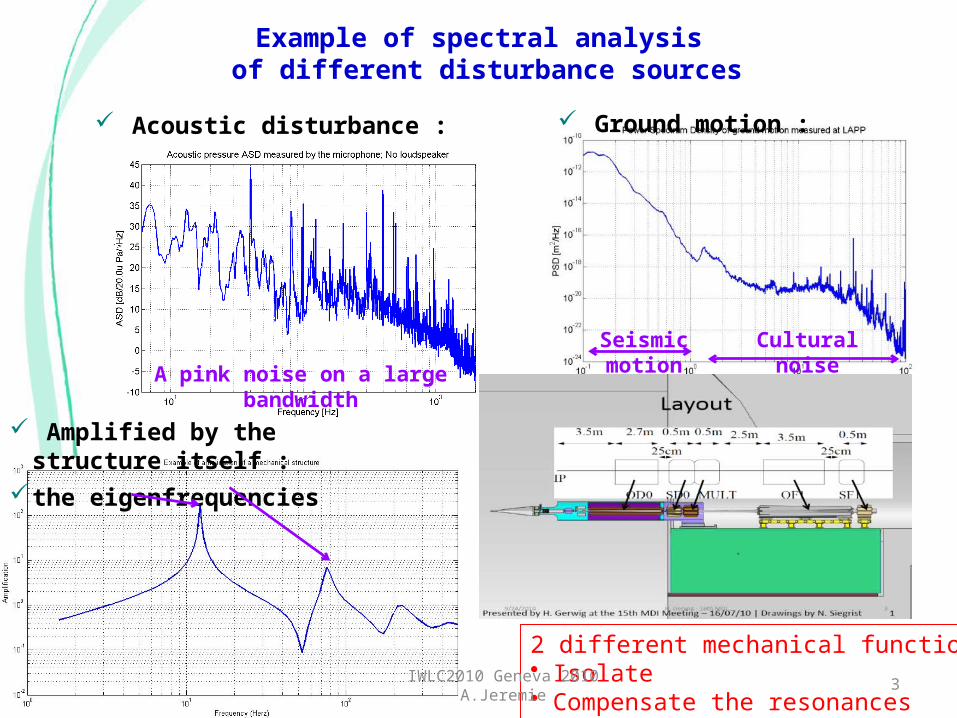
CERN vibration test stand
Sub-Nanometer IsolationCLIC small quadrupole stabilised
to nanometer level by activedamping of natural floor vibration
passive
active
(S.Redaelli 2003)
4IWLC2010 Geneva 2010 A.Jeremie
5
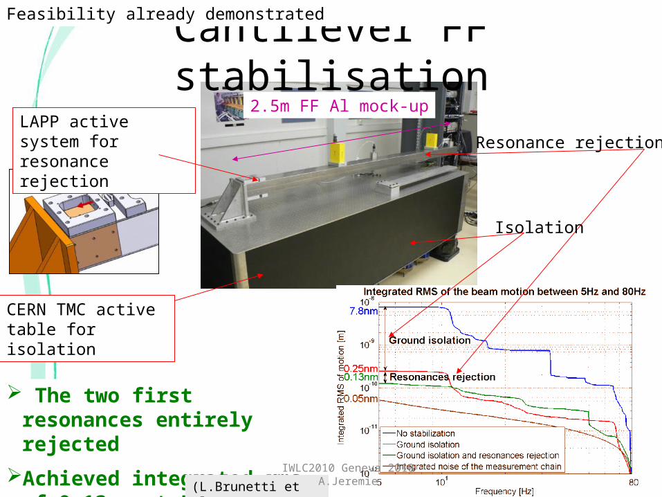
Cantilever FF stabilisation
CERN TMC active table for isolation
The two first resonances entirely rejected
Achieved integrated rms of 0.13nm at 5Hz
LAPP active system for resonance rejection
Isolation
Resonance rejection
(L.Brunetti et al, 2007)
2.5m FF Al mock-up
Feasibility already demonstrated
IWLC2010 Geneva 2010 A.Jeremie

Current studies
6IWLC2010 Geneva 2010 A.Jeremie
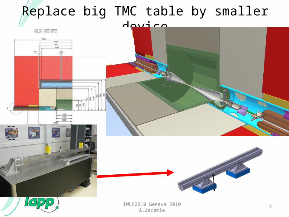
Replace big TMC table by smaller device
7IWLC2010 Geneva 2010 A.Jeremie
8
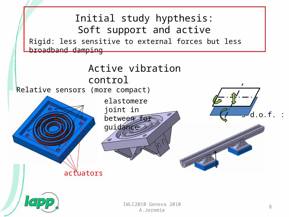
3 d.o.f. :
actuators
Relative sensors (more compact)
elastomere joint in between for guidance
Initial study hypthesis:Soft support and active vibration control
Rigid: less sensitive to external forces but less broadband damping
IWLC2010 Geneva 2010 A.Jeremie
Active vibration control
IWLC2010 Geneva 2010 A.Jeremie 9
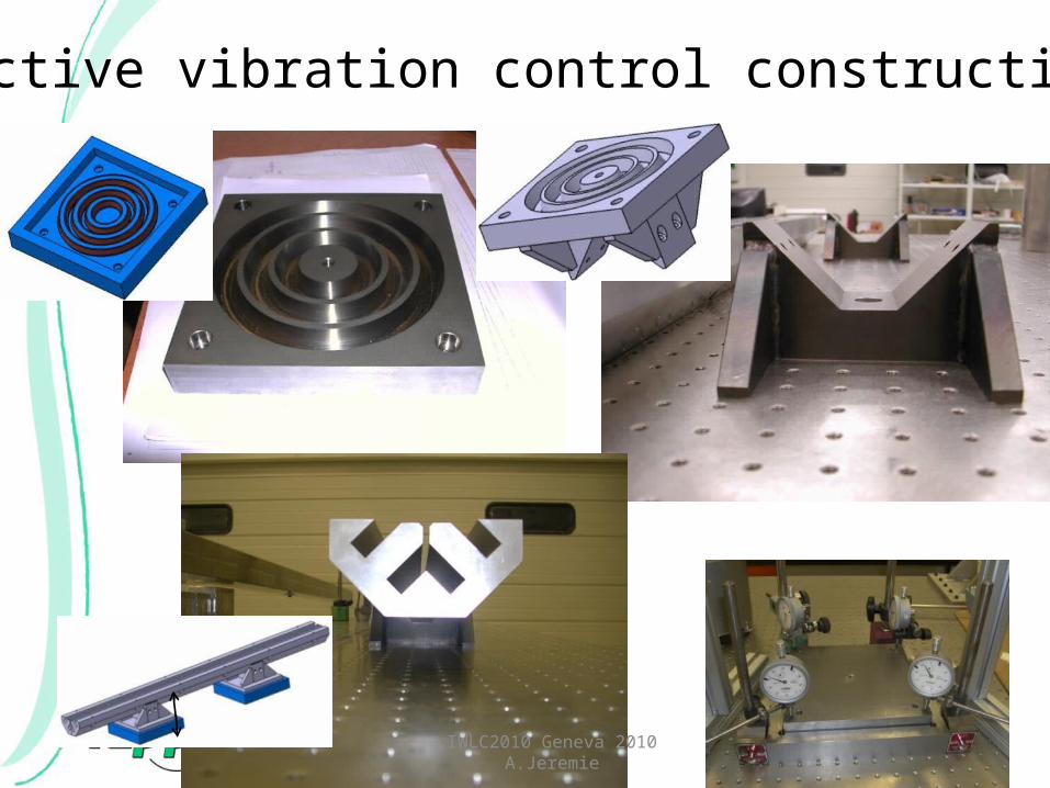
Active vibration control construction
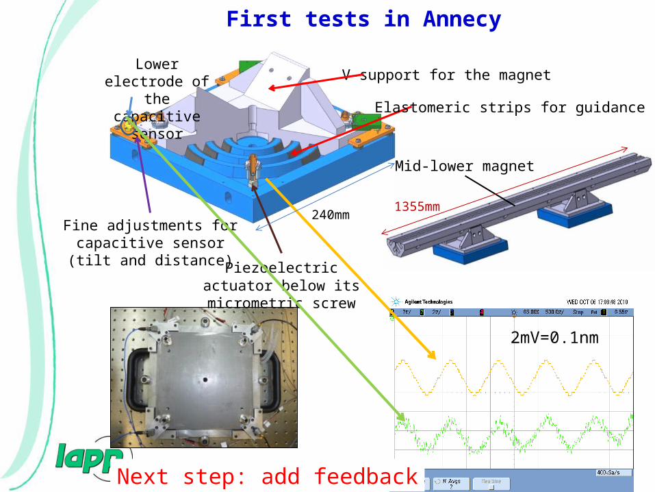
IWLC2010 Geneva 2010 A.Jeremie 10
Mid-lower magnet
1355mm
Elastomeric strips for guidance
Piezoelectric actuator below its micrometric screw
Lower electrode of the capacitive
sensor
Fine adjustments for capacitive sensor (tilt and
distance)
V-support for the magnet
First tests in Annecy
2mV=0.1nm
Next step: add feedback
240mm

11
Later study adding “soft” material
IWLC2010 Geneva 2010 A.Jeremie
IWLC2010 Geneva 2010 A.Jeremie 12
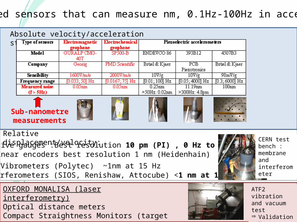
Need sensors that can measure nm, 0.1Hz-100Hz in accelerator
Absolute velocity/acceleration studied at LAPP:
Relative displacement/velocity:
Capacitive gauges :Best resolution 10 pm (PI) , 0 Hz to several kHzLinear encoders best resolution 1 nm (Heidenhain)
Vibrometers (Polytec) ~1nm at 15 HzInterferometers (SIOS, Renishaw, Attocube) <1 nm at 1 Hz
OXFORD MONALISA (laser interferometry)Optical distance metersCompact Straightness Monitors (target 1 nm at 1 Hz)
Sub-nanometre measurements
CERN test bench : membrane and interferometer
ATF2 vibration and vacuum testÞ ValidationÞ Next: optical
test
IWLC2010 Geneva 2010 A.Jeremie 13
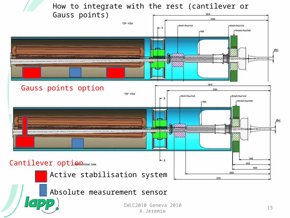
Cantilever option
Gauss points option
How to integrate with the rest (cantilever or Gauss points)
Active stabilisation system
Absolute measurement sensor
IWLC2010 Geneva 2010 A.Jeremie 14
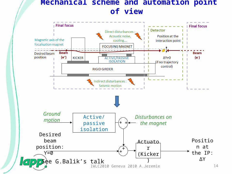
Position at the IP: ∆Y
Ground motion
Desired beam position: Y=0
++
Active/passive isolation
Actuator(Kicker)
Mechanical scheme and automation point of view
+ +Disturbances on the
magnet
See G.Balik’s talk
IWLC2010 Geneva 2010 A.Jeremie 15
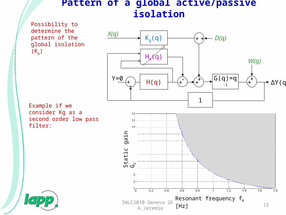
Pattern of a global active/passive isolation
∆Y(q)
X(q)
Y=0 ++ ++
W(q)
Kg(q)
G(q)=q-1+- H(q)
1
+ + D(q)
Ha(q)
+-
Resonant frequency f0 [Hz]
Sta
tic g
ain
Go
Possibility to determine the pattern of the global isolation (Kg)
Example if we consider Kg as a second order low pass filter:
Active/passive isolation
IWLC2010 Geneva 2010 A.Jeremie 16
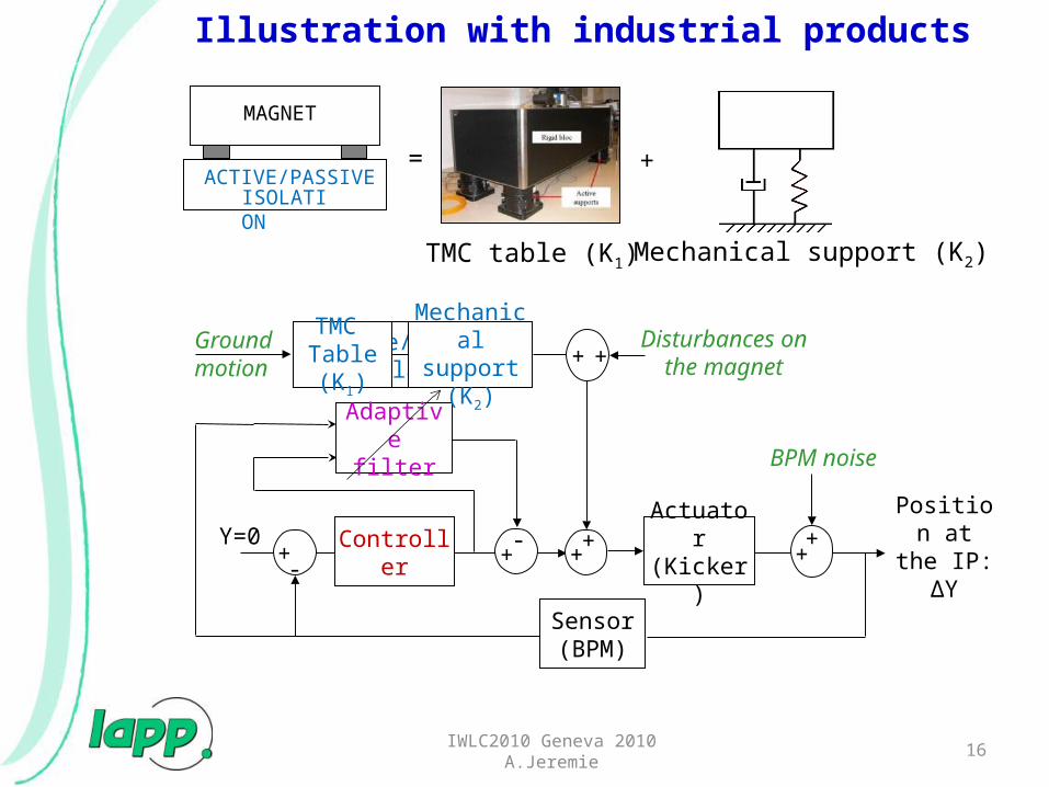
Position at the IP: ∆Y
Groundmotion
Y=0 ++ +
+
BPM noise
Actuator(Kicker)+
-Controller
Sensor(BPM)
+ +Disturbances on the
magnet
Adaptive filter
+-
TMC Table (K1)
Mechanical support (K2)
ACTIVE/PASSIVEISOLATION
MAGNET
= +
TMC table (K1) Mechanical support (K2)
Illustration with industrial products

17IWLC2010 Geneva 2010 A.Jeremie
For the simulation:
The mechanical support behavior is as a first approximation considered as a second order low-pass filter
Inte
gra
ted
RM
S d
isp
lace
me
nt
[m]
Frequency [Hz]
PS
D [
m²/
Hz]
Frequency [Hz]
Results
One single system doesn’t seem enough: need to find the subtle combination of different stabilisation strategies
0.2nm at 0.1Hz
0.018nm at 0.1Hz
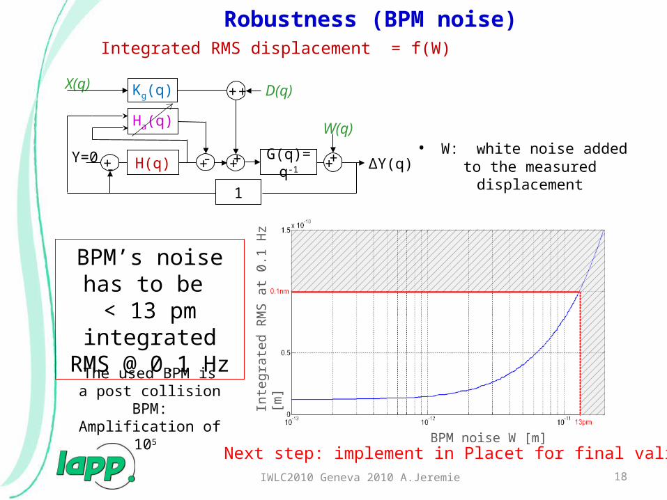
• W: white noise added to the measured displacement
BPM’s noise has to be
< 13 pm integrated RMS @ 0.1 Hz
Integrated RMS displacement = f(W)
18IWLC2010 Geneva 2010 A.Jeremie
Robustness (BPM noise)
∆Y(q)
X(q)
Y=0 ++ ++
W(q)
Kg(q)
G(q)=q-1+- H(q)
1
+ + D(q)
Ha(q)
+-
BPM noise W [m]
Inte
grat
ed R
MS
at
0.1
Hz
[m]
The used BPM is a post collision BPM:
Amplification of 105
Next step: implement in Placet for final validation

Conclusions
19IWLC2010 Geneva 2010 A.Jeremie
• Proof of principle for CLIC FF stabilisation OK for CDR• Need final validation of the technical system better adapted
to tight IR space• Need a more realistic integration scheme
Plans for TDR:• Detailed technical validation• Detailed integration• Final sensor choice (develop a specific sensor?)• Test on short version QD0 prototype (vibration
measurements w/wout cooling and stabilisation…)
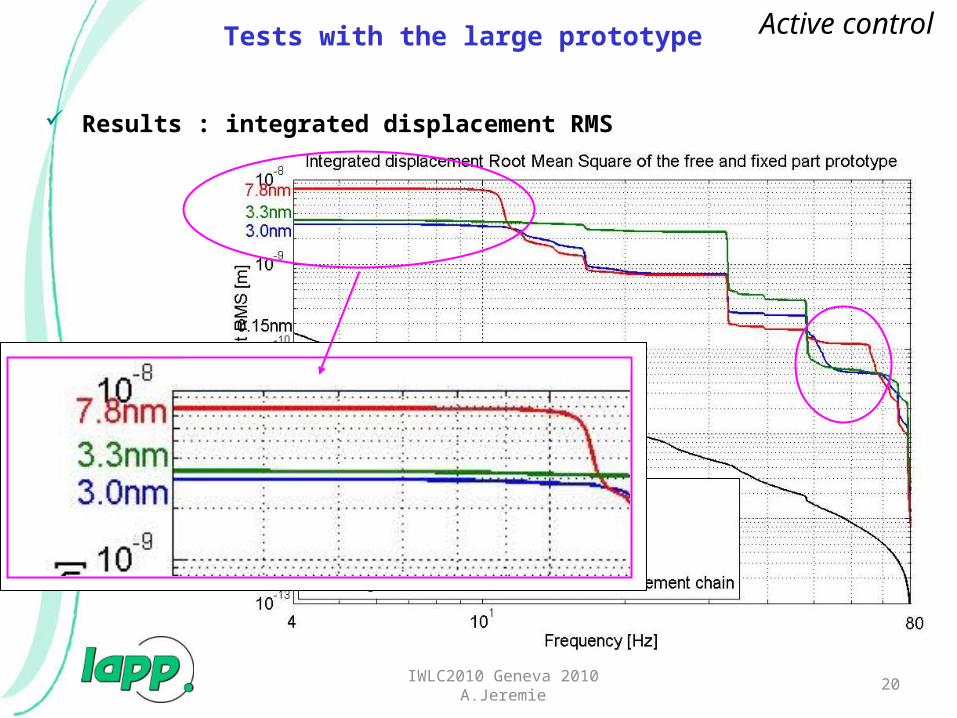
Results : integrated displacement RMS
Tests with the large prototype Active control
20IWLC2010 Geneva 2010 A.Jeremie

Güralp CMG-40TSensor type: electromagnetic geophone broadbandSignal: velocity x,y,zSensitivity: 1600V/m/sFrequency range: 0,033-50HzMass: 7,5kgRadiation: Feedback loop so noMagnetic field: noFeedback loopFirst resonance 440HzTemperature sensitivity: 0,6V/10°CElectronic noise measured at >5Hz: 0,05nmStable calibration
IWLC2010 Geneva 2010 A.Jeremie 21

Endevco 86Sensor type: piezoelectric accelerometerSignal: acceleration zSensitivity: 10V/gFrequency range: 0,01-100Hz but useful from 7HzMass: 771gRadiation: piezo OK, but resin?Magnetic field: probably OK but acoustic vibrations?Feedback loopFirst resonance 370HzTemperature sensitivity: <1%Electronic noise measured at >5Hz: 0,25nm, >50Hz 0,02nmStable calibration, flat responseDoesn’t like shocks
IWLC2010 Geneva 2010 A.Jeremie 22

SP500Sensor type: electrochemical, special electrolyteSignal: velocitySensitivity: 20000V/m/sFrequency range: 0,016-75HzMass: 750gRadiation: no effect around BaBar (don’t know exact conditions)Magnetic field: tested in 1T magnet => same coherence, amplitude? Feedback loopFirst resonance >200HzElectronic noise measured at >5Hz: 0,05nmUnstable calibration, response not flatRobust
IWLC2010 Geneva 2010 A.Jeremie 23