Cleveland “Quickie” Aeronca Chief - 0201.nccdn.net additional artwork is from a redesigned...
16
Cleveland “Quickie” Aeronca Chief This plan package is not a 100% copy of the original kit. As you make your way through the instructions you will see the differences. Here’s just a few of them: The one thing I did stick with was the paint scheme, even though it’s nowhere close to a factory paint scheme from the 40s. The original kit used 1/16” balsa. This plan package uses 1/32” balsa with the exception of the fuselage formers. These are contained on one sheet and the 1/16” thickness is obtained by laminating two 1/32” sheets together. Spray contact cement is used for laminating the sheets together. Liquid cement will cause the balsa to warp. Instructions for a removable nose piece are included. 1/8” Tan II rubber is recommended for the motor. A three-piece wing with a center section is used instead of a one-piece wing like the original The original instructions were very vague. In this plan package they are broken down step-by- step. The complete original instructions are located at the end and include basic tips on how to fly the model. I hope you enjoy it. If you find any errors with the plan package I would greatly appreciate knowing about them. Please contact me at [email protected]
Transcript of Cleveland “Quickie” Aeronca Chief - 0201.nccdn.net additional artwork is from a redesigned...
Cleveland “Quickie” Aeronca Chief This plan package is not a 100% copy of the original kit. As you make your way through the instructions you will see the differences. Here’s just a few of them:
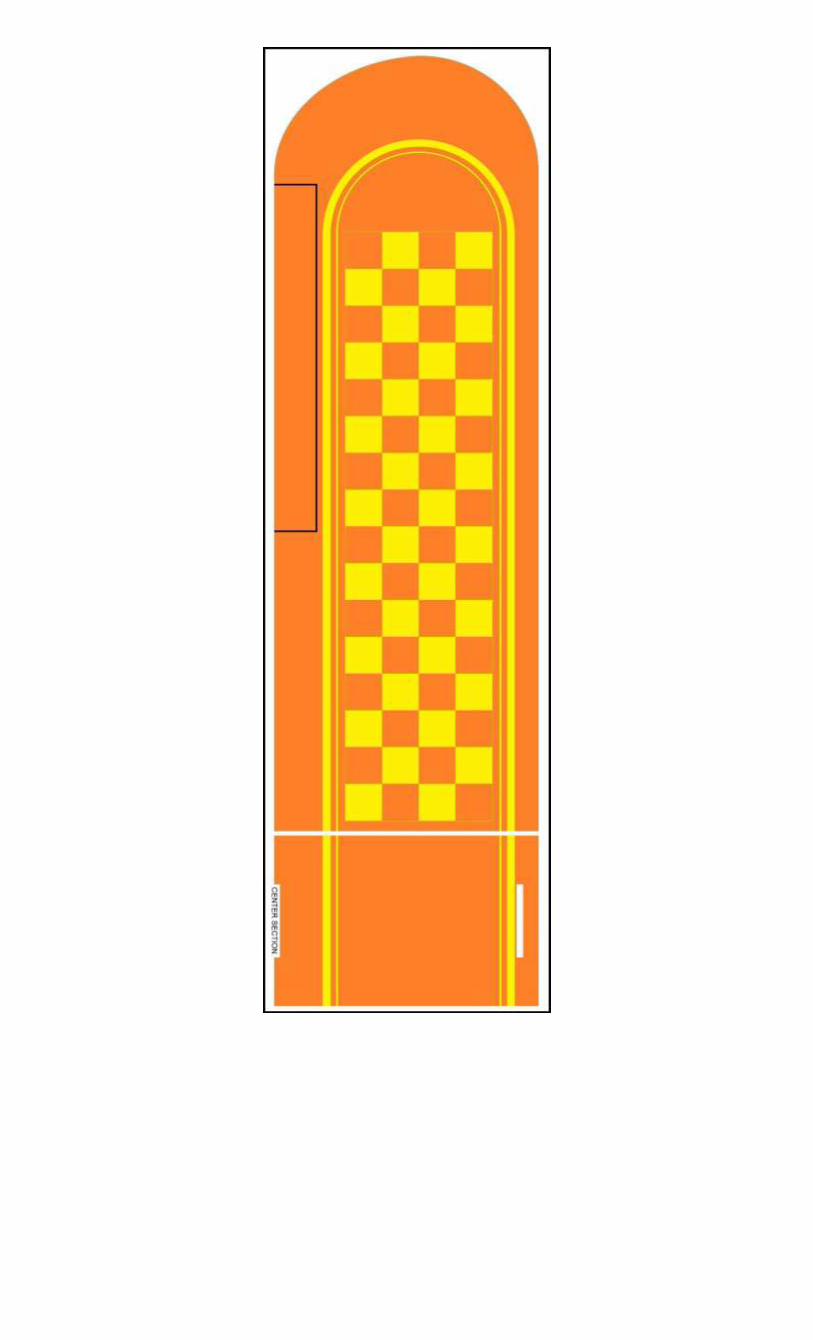
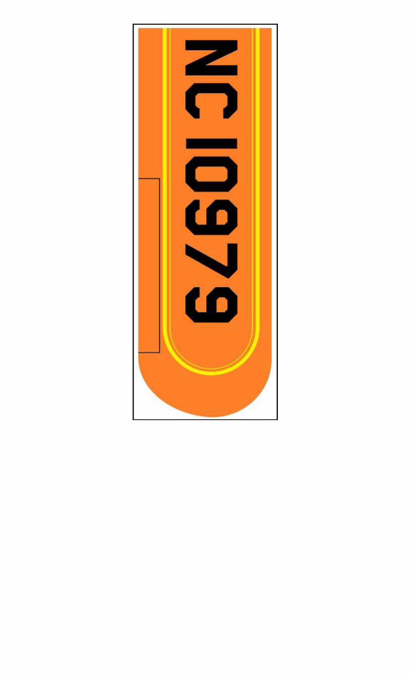
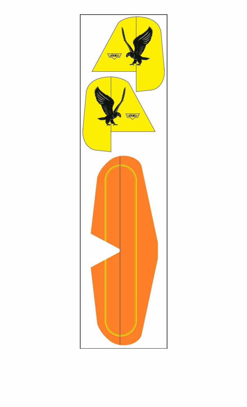
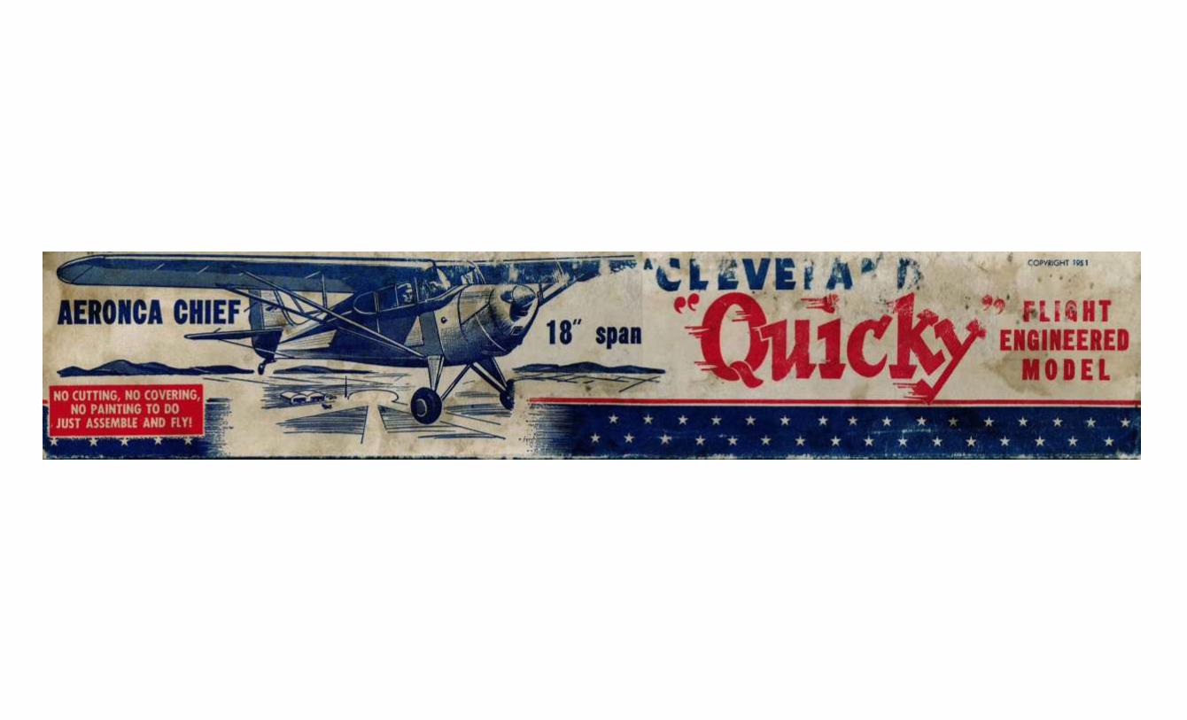
The one thing I did stick with was the paint scheme, even though it’s nowhere close to a factory paint scheme from the 40s.
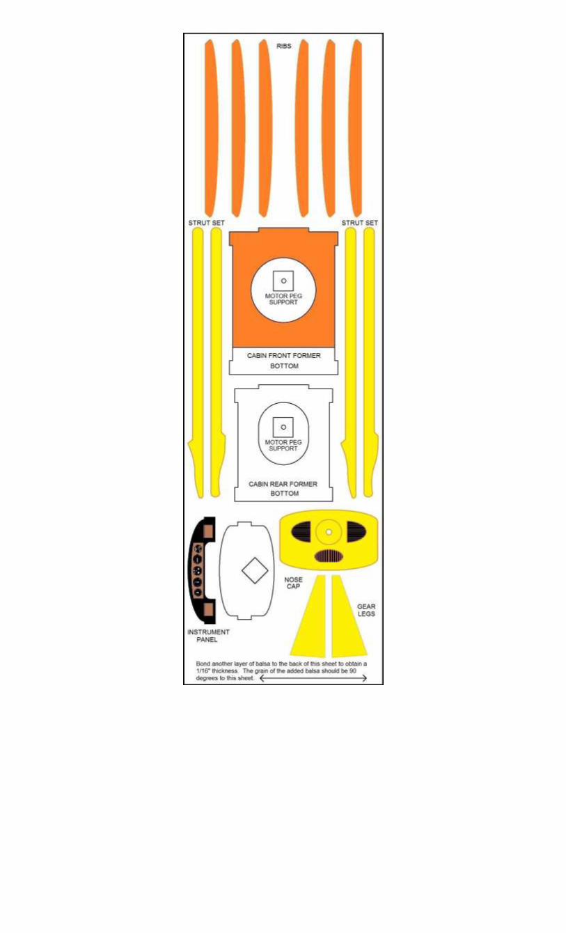
The original kit used 1/16” balsa. This plan package uses 1/32” balsa with the exception of the fuselage formers. These are contained on one sheet and the 1/16” thickness is obtained by laminating two 1/32” sheets together. Spray contact cement is used for laminating the sheets together. Liquid cement will cause the balsa to warp.
Instructions for a removable nose piece are included. 1/8” Tan II rubber is recommended for the motor.
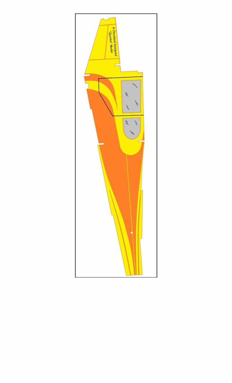
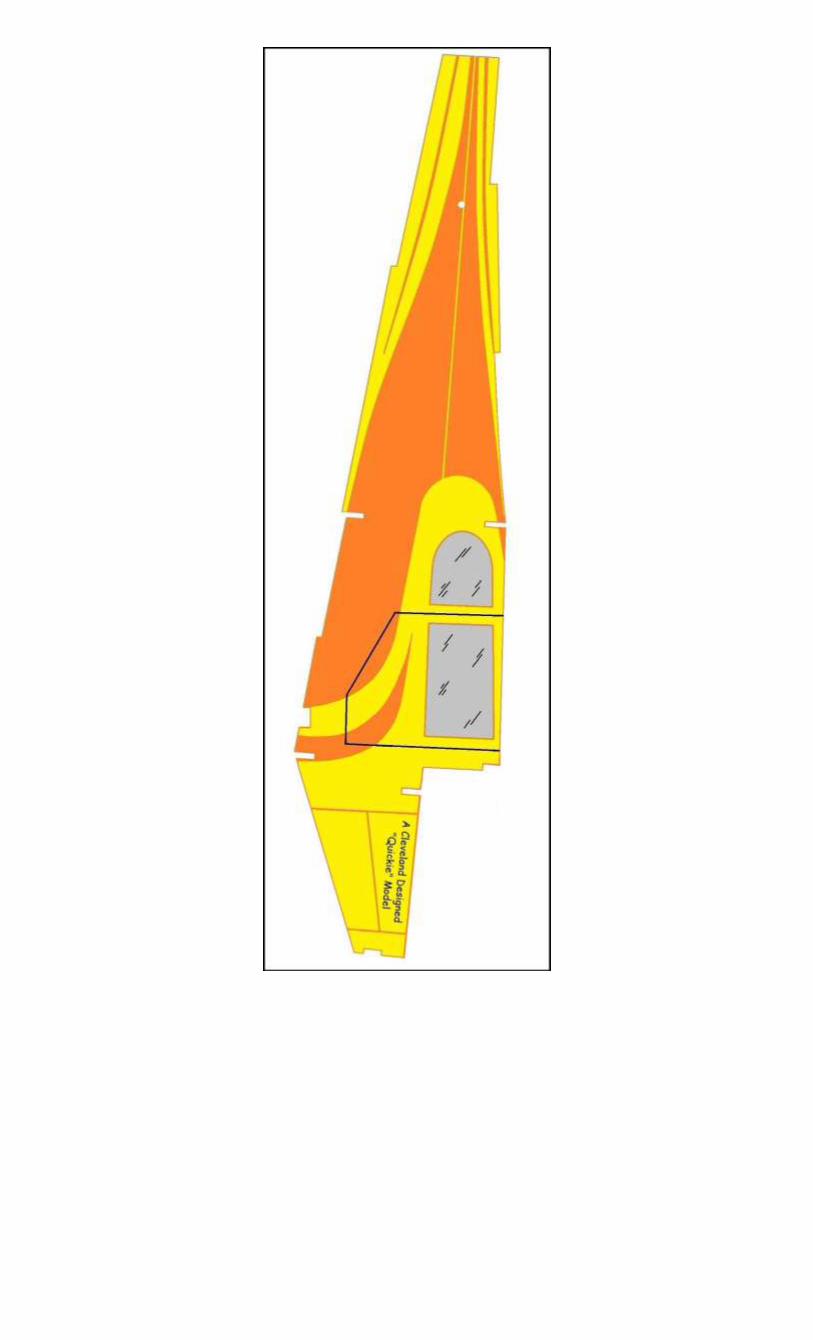
A three-piece wing with a center section is used instead of a one-piece wing like the original
The original instructions were very vague. In this plan package they are broken down step-by-step.
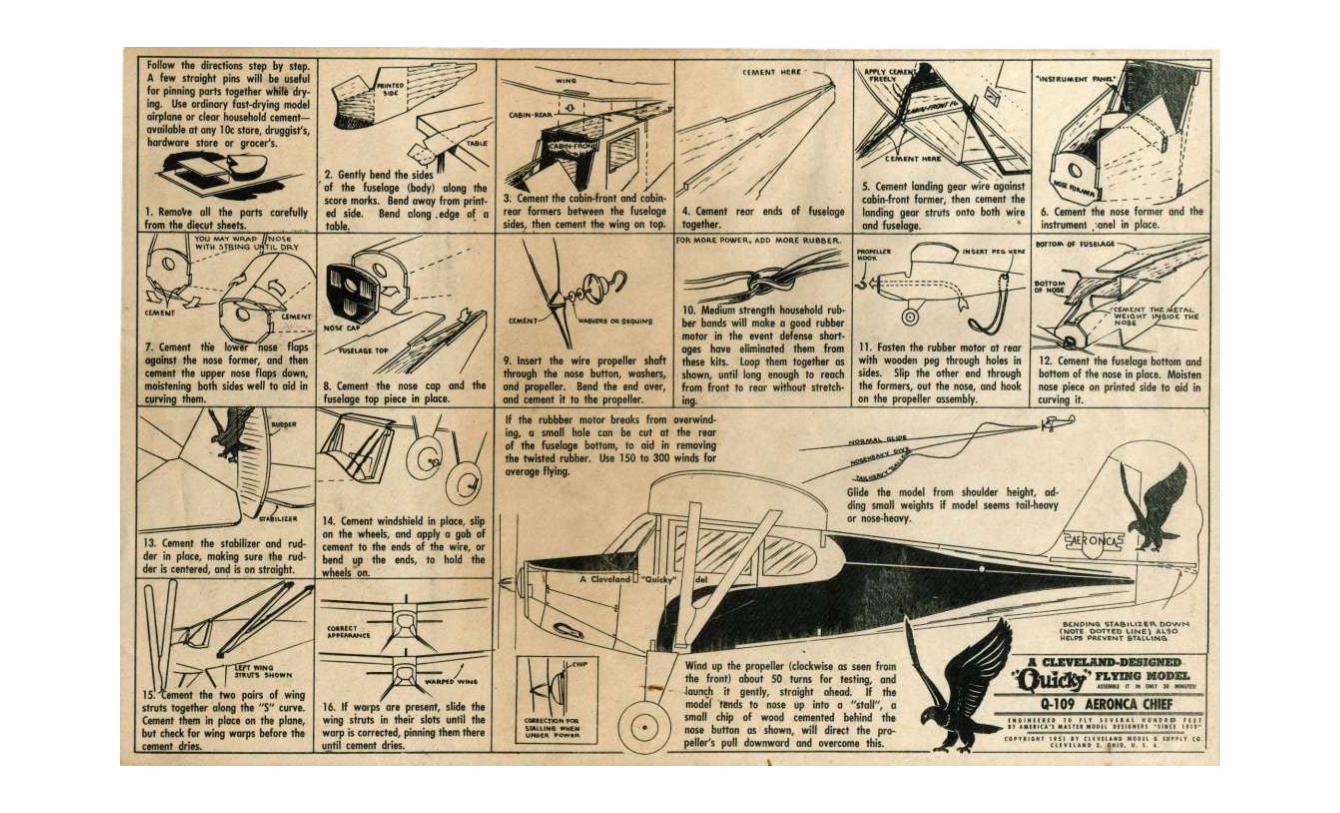
The complete original instructions are located at the end and include basic tips on how to fly the model. I hope you enjoy it. If you find any errors with the plan package I would greatly appreciate knowing about them. Please contact me at [email protected]
Cleveland “Quickie” Aeronca Chief
The original step-by-step instructions are presented here with notes about optional assembly procedures. The additional artwork is from a redesigned Cleveland Quickie Luscombe Sedan kit drawn by Paul Bradley of Parmodels.com. Visit his website to see some great plans for other kits.
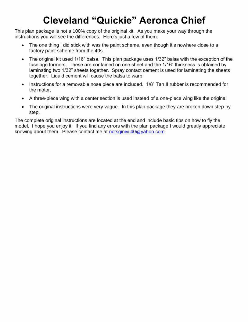
This plan package is not die-cut like the original kit. It is highly recommended that a sharp Xacto® blade be used at all times. Don’t skimp on this or you will tear the wood when cutting it out. Off-brand blades are not as good as the Xacto® brand. When the blade starts to drag, change it out for a new one. It is also best to NOT cut on the lines. Cut the pieces out oversized and sand down to the line. This is especially important when cutting out notches.
I prefer to use Loctite® brand Super Glue. Again, don’t skimp on the brand name. Off-brand cements are inconsistent.
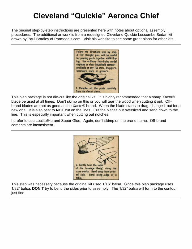
This step was necessary because the original kit used 1/16” balsa. Since this plan package uses 1/32” balsa, DON’T try to bend the sides prior to assembly. The 1/32” balsa will form to the contour just fine.
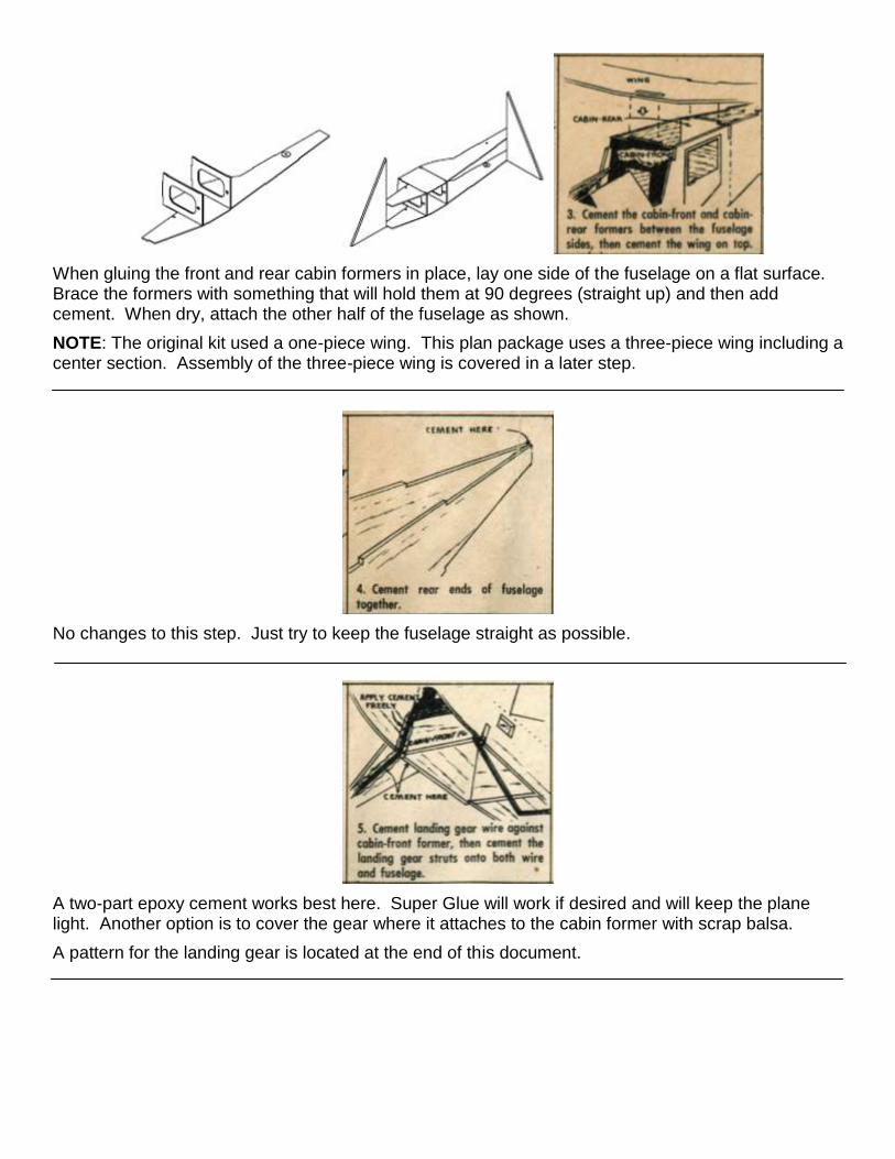
When gluing the front and rear cabin formers in place, lay one side of the fuselage on a flat surface. Brace the formers with something that will hold them at 90 degrees (straight up) and then add cement. When dry, attach the other half of the fuselage as shown.
NOTE: The original kit used a one-piece wing. This plan package uses a three-piece wing including a center section. Assembly of the three-piece wing is covered in a later step.
No changes to this step. Just try to keep the fuselage straight as possible.
A two-part epoxy cement works best here. Super Glue will work if desired and will keep the plane light. Another option is to cover the gear where it attaches to the cabin former with scrap balsa.
A pattern for the landing gear is located at the end of this document.
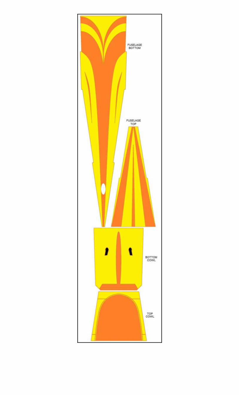
The original kit had each half of the nose cowl included as part of each fuselage side. This has been replaced with a one-piece top and bottom cowl that are oversized so they can be trimmed to fit. The nose former provided in this plan package is intended for a removable nose piece.
As mentioned in the previous step, this plan package has a one-piece top and bottom cowl. Since they are made of 1/32” balsa they should bend to shape the nose without moistening.
The fuselage top can be attached but only do the other steps if you will NOT be using a removable nose piece. When dry the edges of the fuselage top can be sanded flush to the sides.
For the removable nose piece assembly, use the printed piece as a pattern to make up a backing piece from 1/64” plywood. A Peck thrust bearing for a 1/32” prop shaft is recommended. Use a prop in the 5 ½” range. Installation of the rubber motor is made possible by an access hole in the fuselage bottom just below the motor peg.
NOTE: Since the fuselage uses 1/32” balsa it may be advisable to use a small hollow aluminum tube for the rear motor peg.
It shouldn’t be necessary to moisten the nose bottom. If it is, moisten the bare side, not the printed side.
Step 14 shows the windshield glued on top of the wing. Since this plan package has a different wing arrangement, attach the window to the underside of the wing center section. The sides attach as shown. The original kit came with ¾” wheels.
A pattern for the windshield is located at the end of this document.
Three-Piece Wing Assembly Instructions
The original kit used a one-piece, flat wing with no airfoil. This plan package utilizes a three piece wing with ribs added to create a small airfoil.
Before starting this assembly I would like to offer this tip which is completely optional. Since ribs are being added to produce an airfoil, attachment of the ribs can be aided by inducing an airfoil shape into the wing beforehand. In other words, there is a way to bend the wing in order to create a natural airfoil shape. This is accomplished by lightly moistening the wing on the bare balsa side. Then attach it vertically to the side of a five-gallon bucket and allow to dry overnight. There are various ways of attaching it to the bucket such as covering the wing with wax paper and then tape over the wax paper to the bucket. You may have a better way. Again, this is completely optional.
Glue ribs to each side of the wing center section. Glue a rib to the root end of each wing panel. Place a block under each wing that raises the tip to one inch. Using the edge of a work bench as a guide, sand the wing panel root rib flat. This will provide a one inch dihedral for each wing when glued to the center section. The ribs should saddle the fuselage when the wing is glued on. An additional rib is affixed to each wing panel at the start of the aileron outline as indicated by the arrow above. After the rib has been glued in place, trim the bottom of the rib flat. You can also make additional ribs from spare balsa if needed near the tip.
Rib Here
The struts in this plan package are assembled the same but attach to the wing differently. Instead of fitting into slots in the wing, attach the struts to the inboard side of the rib that was attached near the aileron in the previous step. Before gluing into place, the struts can be trimmed to correct any wing warping.