Cleaning and consolidation of the CMS helium …...25/10/16, TE -CRG/C.Fabre 2016 CryoOps workshop...
36
25/10/16, TE-CRG/C.Fabre 2016 CryoOps workshop CMS refrigerator cleaning and consolidation Cleaning and consolidation of the CMS helium refrigerator after hydrocarbon contamination 1 Caroline Fabre on behalf of the TE-CMS cryo task force With contributions from: Johan Bremer, Udo Wagner
Transcript of Cleaning and consolidation of the CMS helium …...25/10/16, TE -CRG/C.Fabre 2016 CryoOps workshop...
25/10/16, TE-CRG/C.Fabre 2016 CryoOps workshop CMS refrigerator cleaning and consolidation
Cleaning and consolidation of the CMS helium refrigerator after hydrocarbon contamination
1
Caroline Fabre on behalf of the TE-CMS cryo task force
With contributions from: Johan Bremer, Udo Wagner
Presenter
Presentation Notes
Abstract: The CMS detector sitting at the CERN Large Hadron Collider uses a large superconducting solenoid magnet. This magnet is cooled in thermosiphon mode by liquid helium at 4.45 K supplied by a dedicated refrigerator. The 2015 operation performance of the refrigerator has been heavily penalized by a peak of Breox® B35 oil contamination. The actions to restore the refrigerator performance were carried out during the 3 month-end-of-the-year technical stop. A new primary oil separator and new coalescers have been installed and commissioned. The adsorbent material has been exchanged. The cold box, installed in an underground service area, has been cleaned using the hydrofluorocarbon Vertrel® XF. After reviewing the causes of the contamination and describing the consolidation of the oil removal system, the presentation will emphasise on the cold box cleaning: agent selection and qualification, method and procedures, cleanliness control points.

25/10/16, TE-CRG/C.Fabre 2016 CryoOps workshop CMS refrigerator cleaning and consolidation 2
Content Refrigerator characteristics 2015 symptoms Causes of contamination Consolidation of oil removal system Cleaning of cold box
agent selection and qualification, methods and procedures, control points
Results Lessons learnt
2

25/10/16, TE-CRG/C.Fabre 2016 CryoOps workshop CMS refrigerator cleaning and consolidation
The CMS refrigerator• 1.5 kW @ 4.5 K equivalent
800 W @ 4.5 K 4500 W @ 60 / 80 K 4 g/s current lead supply
• Compressor station: 0-18 bara; 220 g/s
• Operated for ~10 years withonly minor impurity problems

25/10/16, TE-CRG/C.Fabre 2016 CryoOps workshop CMS refrigerator cleaning and consolidation 4
2015 observed symptoms
4
Temperature gradient developing over first heat-exchanger
Pressure drop developing over turbine 2 inlet filter
Pressure drop developing over 80K adsorber outlet filter
2015 cold box clogging and capacity evolution
ΔP off-set
Pressure drop developing over turbine 1 inlet filter
Presenter
Presentation Notes
Several problems active at the same time. Persistent DP off-set = signature of liquid impurities

25/10/16, TE-CRG/C.Fabre 2016 CryoOps workshop CMS refrigerator cleaning and consolidation
Oil contamination• A considerable amount of Breox® B35
traces was found on1. Outlet filter 80K and 20 K adsorbers2. Inlet filter T13. Inlet filter T24. Turbine gas bearing inlet filters
• Breox® is thought to diminish the heat exchange surface of the first heat-exchanger.
At the same time:• No visible oil traces on piping surfaces• Contamination level measured
downstream of the oil adsorber: Order of magnitude (few ppb(w)) compatible
with the acceptance limit of a new installation No significant signal would be expected at all
…
5
Presenter
Presentation Notes
Breox analysis at the outlet of the oil adsorber: The measurement (Linde Pyroliser) can analyze down to some ppb(v), At this impurity level gives more an indication than a precise value Acceptance limit of a new install <10 ppb(w) but we would expect to see no significant change in signal at all.

25/10/16, TE-CRG/C.Fabre 2016 CryoOps workshop CMS refrigerator cleaning and consolidation 6
Identified causesThe peak of Breox® contamination results from the cumulated effect of:
1. Under-sizing of the oil separatorKnown from 2004 commissioning:• Oil carry over from oil separator ~ 750 ppm(w)• CERN specification: < 100 ppm(w) Compensatory measure = add a 4th coalescer
2. Change of coalescers cartridges brand during 2014 maintenanceClaimed to give equivalent remaining oil aerosol contentsHowever, a factor 4 increase in the separated amount at the last coalescer is measured
3. Change of oil adsorbent material from activated charcoal (coconut shell) to activated coal (anthracite) during 2014 maintenance
Intent: reduce dust, change shape from broken to pelletsCost driven selection
6
Presenter
Presentation Notes
Separated amount at the last coalescer: av. value 2010 to 2012: 0.4 ppmw; 2015: 1.6 ppmw Change of adsorbent material only noticed late summer 2015. All CERN cryo installations concerned. Seen also on smaller scale on ATLAS, but with less consequences. Installations with well performing oil separator and coalescers suffered little.

25/10/16, TE-CRG/C.Fabre 2016 CryoOps workshop CMS refrigerator cleaning and consolidation 7
2015 degraded operation• 2015 average availability: 52%
The installation was kept alive with regular 80K adsorber and turbines inlet filter regeneration and replacement and partial warm-up sequences of the 1st heat exchanger.
Normally a cold-box having suffered such a Breox pollution is stopped to be cleaned. This was however impossible in the CMS case, so we have worked on a continuous operation.
• Consequences for the CMS experiment of the cold-box problems: Of the integrated (p-p) luminosity delivered to CMS, about 73% of the data is
taken under nominal field conditions; The interventions on and regenerations of the CMS cryogenic system have lead
to 12 magnet ramps
7
Presenter
Presentation Notes
In the worse period: max duty cycle would not exceed 10 days 12 interventions per week Turbines’ filter regenerated or exchanged every 3 days on average! The 12 magnet cycles in 2015 is similar to the recurrent observed statistics.

25/10/16, TE-CRG/C.Fabre 2016 CryoOps workshop CMS refrigerator cleaning and consolidation
Consolidation YETS* 2015-16
1. Exchange the final oil separator2. Exchange the coalescer stages3. Exchange the oil adsorbent
material4. Exchange the high pressure piping
between compressor station and cold-box
5. Clean the cold box circuits6. Exchange the 20 K and 80 K
adsorbers
8
*YETS: year end technical stop ~3 months
25/10/16, TE-CRG/C.Fabre 2016 CryoOps workshop CMS refrigerator cleaning and consolidation
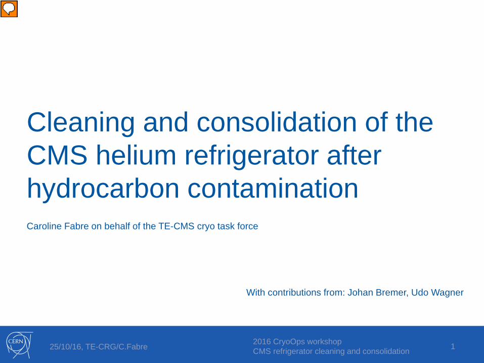
ORS consolidation
Original ORS New ORS
9
On purpose generous design to ensure low oil carry over from the separatorResult (estimate from measurement after 1000h) : ~ 20 ppm(w)
Presenter
Presentation Notes
Source: Udo Wagner Assumed: 1st coalescer separation 380 mL/day Better than 90% efficiency (95%) of each coalescer stage, i.e. a factor 20 4000 h expected before saturation of second stage Oil carry over from oil separator expected 400ml/day (for 220 g/s 100 mL/ day 5.2 ppm(w)) Won’t see oil in the 3rd during the present run!
25/10/16, TE-CRG/C.Fabre 2016 CryoOps workshop CMS refrigerator cleaning and consolidation 10
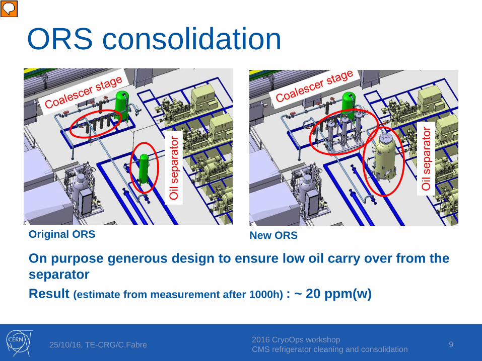
Cold-box cleaning• History recall:
One major accident of oil contamination in 2004: ~ 2L accumulated in the cold box
System installed at the surface for commissioning Cleaning agent: isopropyl alcohol Very difficult drying afterwards: ~1 month
• 2016 cleaning: In underground environment Cleaning agent: DuPontTM Vertrel® XF (C5H2F10)
Density: 1.6 kg/L @ 25°CBoiling point: 55°C @ 1013 mbarVapor pressure: 301 mbar @ 25°C
10
Presenter
Presentation Notes
Hydrofluorocarbon (HFC) See back-up slides for data sheets

25/10/16, TE-CRG/C.Fabre 2016 CryoOps workshop CMS refrigerator cleaning and consolidation 11
Solvent selection and qualification• Criteria for the selection of Vertrel® XF
No flammability range (personal safety in the case of underground operation) Low toxicity, environmental compatibility Miscible with Breox® B35 (cleaning efficiency) Easy to dry out of the system after cleaning (~rate of evaporation):
high vapour pressure (301 mbar @ 25°C), low latent heat (136.5 kJ/kg @ 25°C)
Compatible with cold-box materials (metals, plastics, elastomers)
Safety measures: trained personnel, PPE, air extraction, spill containment tray, ODH detection
• Qualification tests with chemistry lab Cleaning efficiency tests Exhaustive inventory of plastics & elastomers present in the cold-box circuits Immersion tests carried out on samples of each material to assess mass increase and
degradation
Only Viton turned out to be sensible to Vertrel® XF: mass increase (absorption) in presence of
either liquid or vapor phase of Vertrel® XF. Exchanged at the end of cleaning.
11
Presenter
Presentation Notes
Miscible = forms a homogeneous phase ODH: vapours are heavier than air and can cause suffocation by reducing oxygen available for breathing Purpose of materials compatibility : keep as much as possible of the installed equipment for the cleaning. Limit instrumentation handling as dominates material risk / intervention time Remove/isolate fragile instrumentation Keep useful and solvent-compatible instrumentation Material list: PE-HML 500, Viton, KEL-F (PCTFE), PTFE, PTFE reinforced, TFE/PTFE reinforced fibre glass, Graphite

25/10/16, TE-CRG/C.Fabre 2016 CryoOps workshop CMS refrigerator cleaning and consolidation 12
Cleaning quality control• FT-IR In-Situ measurement of Breox® B35 in Vertrel® XF
Detection limit: 10 mg/L Analysis time: 5 min.
12
Special development by CERN Chemistry Lab.
20 µlBreox B35 + Solvent
Solvent Evaporation
BreoxB35
Substrate
Mirror
Detector
IR Beam
Courtesy: Benoit Teissandier, CERN Vacuum, surfaces & Coatings group
25/10/16, TE-CRG/C.Fabre 2016 CryoOps workshop CMS refrigerator cleaning and consolidation 13
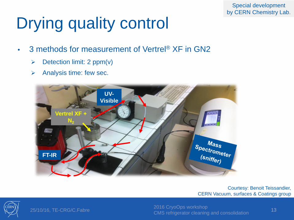
Drying quality control• 3 methods for measurement of Vertrel® XF in GN2
Detection limit: 2 ppm(v) Analysis time: few sec.
13
Courtesy: Benoit Teissandier, CERN Vacuum, surfaces & Coatings group
UV-Visible
FT-IR
Vertrel XF + N2
Special development by CERN Chemistry Lab.
25/10/16, TE-CRG/C.Fabre 2016 CryoOps workshop CMS refrigerator cleaning and consolidation
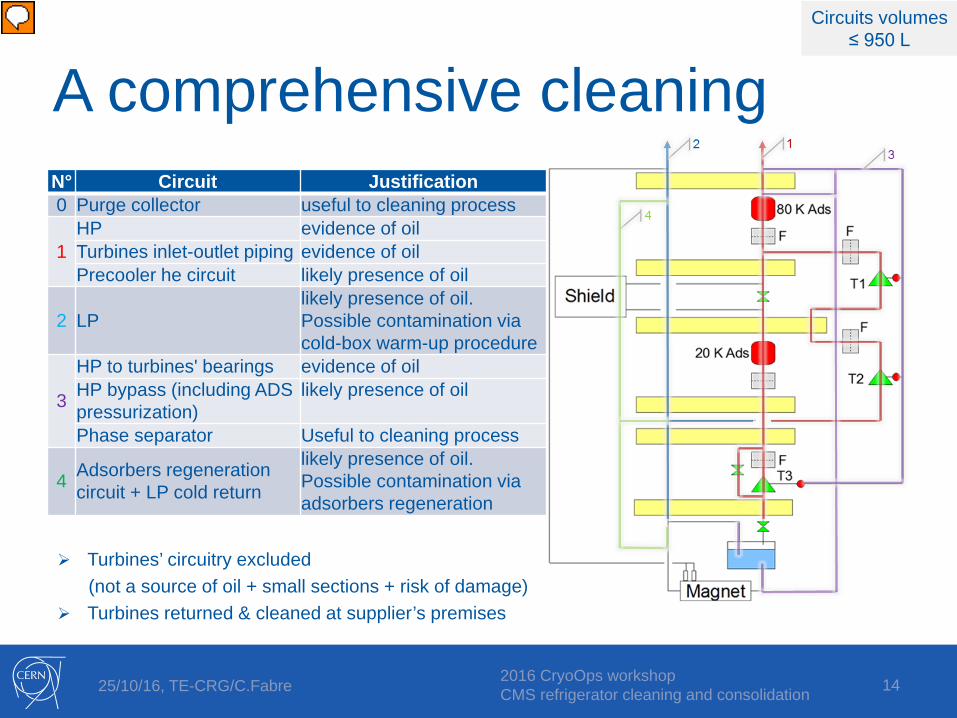
Turbines’ circuitry excluded (not a source of oil + small sections + risk of damage)
Turbines returned & cleaned at supplier’s premises
N° Circuit Justification0 Purge collector useful to cleaning process
1HP evidence of oilTurbines inlet-outlet piping evidence of oilPrecooler he circuit likely presence of oil
2 LPlikely presence of oil. Possible contamination via cold-box warm-up procedure
3
HP to turbines' bearings evidence of oilHP bypass (including ADS pressurization)
likely presence of oil
Phase separator Useful to cleaning process
4 Adsorbers regeneration circuit + LP cold return
likely presence of oil. Possible contamination via adsorbers regeneration
A comprehensive cleaning
14
Circuits volumes≤ 950 L
Presenter
Presentation Notes
CB has been divided into 4 independent circuits to be cleaned Circuits volumes: 1: 500L 2: 950 L 3&4: 215L

25/10/16, TE-CRG/C.Fabre 2016 CryoOps workshop CMS refrigerator cleaning and consolidation
Cold box preparation (1/2)
15
Heavy pipework modifications: New connections for solvent in/out
New high ventilating points
New gravity drain points Lines towards client cut unless
isolated by two leak-tight valves
After, with new connectionsBefore
High ventilating points

25/10/16, TE-CRG/C.Fabre 2016 CryoOps workshop CMS refrigerator cleaning and consolidation
Cold box preparation (2/2)
16
Removed:• Adsorbers (x2)• Turbines (x3)• Turbines instrum.• Filter cartriges (x6)• Lakeshore TE (x22)
Kept:• Cryo valves (x20)• Purge valves (x53)• PT/DPT valve blocks
(sensor isolated) (x15)• Safety valves (x18)
Heat exchangers :• Add purge tapping• Add drain tapping• Shim to secure
supporting
Presenter
Presentation Notes
The adsorbers were removed and shunted. All filters have been removed. The dummy turbines have been installed. The temperature sensors have been removed. Any other instrumentation was left in. Tappings have been made in the first two heat exchangers (top and bottom) to control the absence of gas at the top of the heat exchangers and to drain the biggest volumes by gravity.

25/10/16, TE-CRG/C.Fabre 2016 CryoOps workshop CMS refrigerator cleaning and consolidation
Cleaning method
17
• Forced circulation of pressurized (2-4 bara) cleaning agent in the contaminated circuits
• Flow direction from clean towards contaminated parts
• Circulate in parts in contact with process flow, NOT in dead ends (pressure sensors piping, cryovalve bodies)
• Flush circuit derivations / branches in sequence
• “Cleaning” machine bought on purpose Method & equipment validated
beforehand on a test stand
Solvent inventory: 2 m3
Presenter
Presentation Notes
Pressurized = sub-cooled to guaranty wetting of all surfaces 2 m3 of solvent inventory defined after the biggest circuit volume (950 L) and taking into account continuous purification of “dirty” solvent.

25/10/16, TE-CRG/C.Fabre 2016 CryoOps workshop CMS refrigerator cleaning and consolidation 18
Cleaning procedure& control points
18
Dryingprocedure
Leaktight
Sectorize circuit n°xIsolate instrumentationPressurize circuit with GN2
Evacuatecircuit
Suction fillcircuit to ~250 mbara
Pressurize with pumpto ~2 baraAssess volume
Leaktight
Purge HX + top partSample analysis
All surfaces
wet
CirculateL-solvent + Sample analysis
Asymptotic Breox content AND full circuit volume displacedonce AND all branches flushed
OR out of clean solvent
Y
N
Stopcirculation
Drain by gravity+ GN2 pressure as far as possible
Distillatesolvent
Clean circuit:
<10 mg/L
YN
Duration per circuit: 2–3 working days
Sample at HX1
Presenter
Presentation Notes
Useful to purge top HX and lines. Allowed to correct wrong manipulations like pump cavitation on low solvent level introducing air in the circuit Flush derivations / branches according to transport time Stop circulation for the time of sample analysis At least one renewal of complete volume even if «clean» analysis Distillation at the same time all the time but very slow 40L/h. No circulation over night. Use night for solvent purification.

25/10/16, TE-CRG/C.Fabre 2016 CryoOps workshop CMS refrigerator cleaning and consolidation 1919
1. Vaporize the residual liquid-phase solvent after drain: • Maintain temperature ~40°C: Circulate warm gaseous nitrogen
in counter-flow circuit (not the cleaned circuit)
Blow warm air through cold-box vacuum tank
• Pump cleaned circuit down to Pvapor~280 mbar < Psat
• Re-condense vapors Drying speed depends on free
surface area2. Flush the residual vapor-phase
solvent: • Circulate warm gaseous
nitrogen in the cleaned circuit3. Outgas under vacuum
Drying method
Presenter
Presentation Notes
Bring heat to maintain temperature. Max admissible temperature on HX : 60°C Regulate pressure lower than saturated but corresponding to a saturated temperature above dew point to prevent condensation of humidity in MLI in case of heating failure…

25/10/16, TE-CRG/C.Fabre 2016 CryoOps workshop CMS refrigerator cleaning and consolidation 20
Drying procedure& control points
20
N
Circuit dry: sudden P drop
+ T rise P <10 mbar
Start condenserStart vacuum pump and regulatepressure to ~250 mbarStart warm GN2 circulation in HX 2nd circuit (not in the cleaned circuit)
Start fan heater
Stop purge pumpStop GN2 circulation in HX
Y
Flush withwarm GN2
48h Stop flushing + solvent residualanalysis
Pump circuit (24h or more) and isolate under staticvacuum for outgassing (2h)
Pressurizewith GN2
Stop fan heaterEnd of dryingprocedure
Solventanalysis in GN2
< 10 ppmv
Nota: most outgassing items (Viton O-rings) exchanged during cold-box reconstruction
Duration per circuit: 2–3 working days
Presenter
Presentation Notes
Signature of a dry circuit (i.e. no more liquid): Sudden drop of pressure Sudden rise of temperature
25/10/16, TE-CRG/C.Fabre 2016 CryoOps workshop CMS refrigerator cleaning and consolidation 21
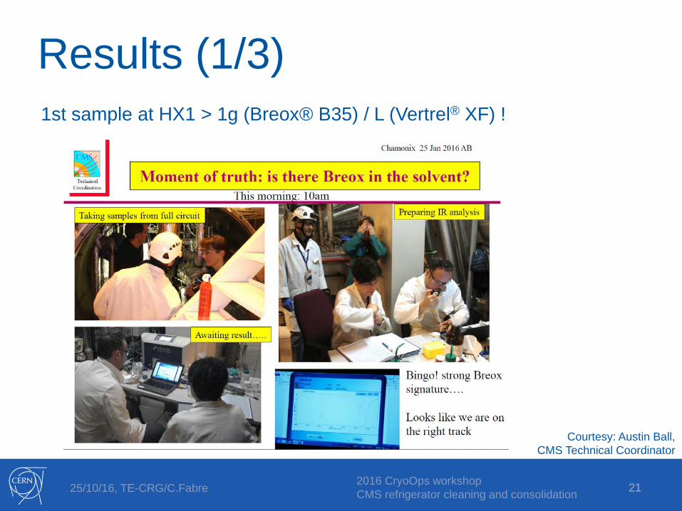
Results (1/3)1st sample at HX1 > 1g (Breox® B35) / L (Vertrel® XF) !
21
Courtesy: Austin Ball, CMS Technical Coordinator

25/10/16, TE-CRG/C.Fabre 2016 CryoOps workshop CMS refrigerator cleaning and consolidation 22
Results (2/3)Circuit 1-HP: ~260 L of Vertrel® XF drained and ~300 L dried in < 1 day !
22
Cleaning machine & condenser
Cold box ambient conditions: 40°C !
End of drying signature

25/10/16, TE-CRG/C.Fabre 2016 CryoOps workshop CMS refrigerator cleaning and consolidation 23
• In total 375 g of Breox® B35 extracted from the cold-box• Low outgassing rate of Vertrel® XF (< 100 ppm(v) over few days)
• A 2.5 month intervention
Results (3/3)
Circuit Duration Circuit volume
(L)
Effective cleaning time (h)
Breoxamount
collected
Drained volume
(L)
Drying time(h)
Residual Vertrel® XF (ppm(v))*
Circuit 1:clean & dry
1 week 550(HX1: 115)
3 353 260(~50%)
< 24 < 10
Circuit 2:clean & dry
1 week 950 (HX1: 350)
2 10 760(~80%)
< 24 < 10
Circuit 3&4:clean & dry
1 week 250(PSD: 150)
1.5 13 190(~75%)
< 24 ~20
23
Preparation of cold-box and ancillary equipment
circuit 1: clean & dry
circuit 2: clean & dry
circuit 3&4: clean & dry
Overall outgasingand purge
Re-construction of cold-box
3 weeks 1 week 1 week 1 week 1 week 3 weeks
* after exchange of most outgassing items (Viton O-rings)
Presenter
Presentation Notes
Circuit 1 (HP + HX1) most contaminated circuit as expected Cleaning itself is very quick and efficient. Time consuming is circuit preparation, analyses… Sequence: 1-2 days for cleaning, 1 day for drain and dry, 1-2 days GN2 flushing and preparation of next circuit Managed to drain more than expected Outgassing: 10 days + time of cold box reconstruction

25/10/16, TE-CRG/C.Fabre 2016 CryoOps workshop CMS refrigerator cleaning and consolidation 24
Lessons learnt• Cleaning a cold-box is a heavy intervention.
… which nevertheless spared another 4000 clogged turbine filter exchanges … Cleaning the HP branches would probably do it Purge and drain tappings in biggest HX is worth it Prevention is better than cure!
• Even very small amounts of oil in process flow will accumulate over years. (Present specification < 10 ppb(w))
We would like NO significant oil signal at the outlet of the oil adsorber
• The primary oil separator is an important element in the oil removal system.
The bad performance of a separator cannot be (fully) recovered by adding coalescers
We seriously consider to tighten the specified limit of 100 ppm(w)
• Be weary in case different / cheaper alternatives for spares or replacement material is proposed.
24
Presenter
Presentation Notes
CMS average 2015: 10 ppb(w) (within spec limit) 10-8 * 190g/s * 3600s* 8000h = 55g in one year Pyroliser reading in ppb(v) 1 ppb(v) reading 10-9*60/4*190g/s*3600s*8000h = 80g in a year of operation

25/10/16, TE-CRG/C.Fabre 2016 CryoOps workshop CMS refrigerator cleaning and consolidation 25
• The smoothest behaviour ever observed with this cold-box.… more oil removed than accumulated during and after LS1*.
• The result of a team effort (cryogenics – vacuum, surfaces & chemistry – safety – CMS – mechanics – cooling – transport …)
Nominal functioning through 2016
25
*LS1: Long shut-down 2013-14
2016
col
d bo
x cl
oggi
ng a
nd c
apac
ity e
volu
tion
Stable temperature gradient over first heat-exchanger
No pressure drop evolution over turbine 1 & 2 inlet filters
Reserve cold box power
Technical stop Electrical perturbationEthernet com. failure
Turbines stop

25/10/16, TE-CRG/C.Fabre 2016 CryoOps workshop CMS refrigerator cleaning and consolidation
Back-up slides
26

25/10/16, TE-CRG/C.Fabre 2016 CryoOps workshop CMS refrigerator cleaning and consolidation 27
CMS cryogenics
27
CMS central solenoid CMS cold box
CMS compressor station (2012)

25/10/16, TE-CRG/C.Fabre 2016 CryoOps workshop CMS refrigerator cleaning and consolidation 28
Process parameters (1/2)
28
May 2016

25/10/16, TE-CRG/C.Fabre 2016 CryoOps workshop CMS refrigerator cleaning and consolidation 29
Process parameters (2/2)
29
May 2016

25/10/16, TE-CRG/C.Fabre 2016 CryoOps workshop CMS refrigerator cleaning and consolidation 30
CMS filter clogging 2011 to 2015
30
Courtesy: Udo Wagner, CERN Cryogenics group

25/10/16, TE-CRG/C.Fabre 2016 CryoOps workshop CMS refrigerator cleaning and consolidation
DuPontTM Vertrel® XF
31

25/10/16, TE-CRG/C.Fabre 2016 CryoOps workshop CMS refrigerator cleaning and consolidation
SolventDensity Vaporisation
heatVapour
pressureBoiling point
Freezing point
Flash point LFL UFL Cleaning cp
kg/m3 kJ/kg @ 25°C mmHg @ 25°C °C °C °C % % kJ/kgK
Isopropanol 786 732 40 83 -89 11.7 2 12 Y 2.622Acetone 791 518 230 56 -95 -20 3 13 Y 2.299
Petroleum ether 650 - 232 52 -73 0 1 6 Y 1.760Modified alcohol 880 280 0.8 172 -75 63 1 8 ?Y 2.000Perfluorohexane 1669 96 202 56 -90 No No No N 0.250
Methylene chloride 1330 330 430 40 -97 No 13 23 ?Y 1.200Vertrel Sion 1279 226 331 48 -50 No 7 14 Y 1.069
Novec HFE 71 IPA 1420 165 207 55 -135 No 4 17 Y 0.800VERTREL XP 1530 ~165 253 52 -80 No No No Y ~0.800VERTREL XF 1580 129.7 226 55 -84 No No No Y 1.130SOLREM 43i 1430 - - 50 -30 No - - Y -
Water 1000 2441 24 100 0 No No No ?Y 4.186
32
Cle
anin
g ag
ent
Main properties:
o
Courtesy: Leonel Ferreira, CERN Vacuum, surfaces & Coatings group
25/10/16, TE-CRG/C.Fabre 2016 CryoOps workshop CMS refrigerator cleaning and consolidation
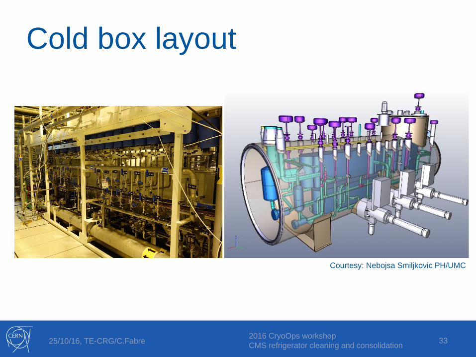
Cold box layout
33
Courtesy: Nebojsa Smiljkovic PH/UMC

25/10/16, TE-CRG/C.Fabre 2016 CryoOps workshop CMS refrigerator cleaning and consolidation
Heat exchangers (HX)• Restriction = candidate oil trap• Horizontal aluminum brazed
plates• 6 HX - 12 circuits • HX circuits volume ranges
from 10L to 350L• Ensure HX filling with solvent
Filling of HX validated on test stand
Purge tappings made in HX1&2 as control points
34
Echangeur à plaques brasées (source: doc. Nordon)
E têteF ailette discontinue
E
F

25/10/16, TE-CRG/C.Fabre 2016 CryoOps workshop CMS refrigerator cleaning and consolidation 35
Results (1/2)
35
Take sample at HX1 HX1 full
Take sample on return line Cleaning quality «on-line» analysis