CLEANER, STEAM PRESSURE JET SKID MOUNTED MODEL: RI …
113
TM 9-4940-556-14&P TECHNICAL MANUAL OPERATOR, ORGANIZATIONAL, DIRECT SUPPORT & GENERAL SUPPORT MAINTENANCE MANUAL INCLUDING REPAIR PARTS LIST FOR CLEANER, STEAM PRESSURE JET SKID MOUNTED MODEL: RI 2400 (NSN 4940-00-186-0027) HEADQUARTERS, DEPARTMENT OF THE ARMY 11 JUNE 1986
Transcript of CLEANER, STEAM PRESSURE JET SKID MOUNTED MODEL: RI …
TM 9-4940-556-14&P
TECHNICAL MANUAL
OPERATOR, ORGANIZATIONAL, DIRECT
SUPPORT & GENERAL SUPPORT
MAINTENANCE MANUAL INCLUDING
REPAIR PARTS LIST
FOR
CLEANER, STEAM PRESSURE
JET SKID MOUNTED
MODEL: RI 2400
(NSN 4940-00-186-0027)
HEADQUARTERS, DEPARTMENT OF THE ARMY
11 JUNE 1986

TM 9-4940-556-14&P
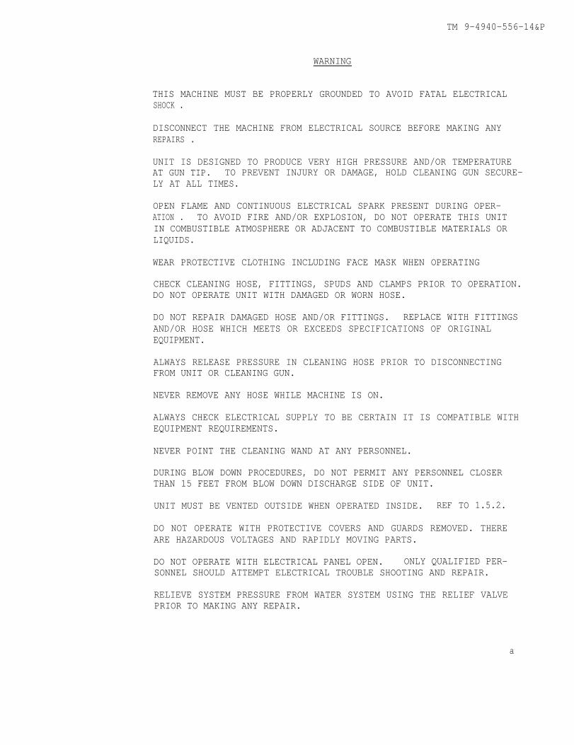
WARNING
THIS MACHINE MUST BE PROPERLY GROUNDED TO AVOID FATAL ELECTRICALSHOCK .
DISCONNECT THE MACHINE FROM ELECTRICAL SOURCE BEFORE MAKING ANYREPAIRS .
UNIT IS DESIGNED TO PRODUCE VERY HIGH PRESSURE AND/OR TEMPERATUREAT GUN TIP. TO PREVENT INJURY OR DAMAGE, HOLD CLEANING GUN SECURE-LY AT ALL TIMES.
OPEN FLAME AND CONTINUOUS ELECTRICAL SPARK PRESENT DURING OPER-ATION . TO AVOID FIRE AND/OR EXPLOSION, DO NOT OPERATE THIS UNITIN COMBUSTIBLE ATMOSPHERE OR ADJACENT TO COMBUSTIBLE MATERIALS ORLIQUIDS.
WEAR PROTECTIVE CLOTHING INCLUDING FACE MASK WHEN OPERATING
CHECK CLEANING HOSE, FITTINGS, SPUDS AND CLAMPS PRIOR TO OPERATION.DO NOT OPERATE UNIT WITH DAMAGED OR WORN HOSE.
DO NOT REPAIR DAMAGED HOSE AND/OR FITTINGS. REPLACE WITH FITTINGSAND/OR HOSE WHICH MEETS OR EXCEEDS SPECIFICATIONS OF ORIGINALEQUIPMENT.
ALWAYS RELEASE PRESSURE IN CLEANING HOSE PRIOR TO DISCONNECTINGFROM UNIT OR CLEANING GUN.
NEVER REMOVE ANY HOSE WHILE MACHINE IS ON.
ALWAYS CHECK ELECTRICAL SUPPLY TO BE CERTAIN IT IS COMPATIBLE WITHEQUIPMENT REQUIREMENTS.
NEVER POINT THE CLEANING WAND AT ANY PERSONNEL.
DURING BLOW DOWN PROCEDURES, DO NOT PERMIT ANY PERSONNEL CLOSERTHAN 15 FEET FROM BLOW DOWN DISCHARGE SIDE OF UNIT.
UNIT MUST BE VENTED OUTSIDE WHEN OPERATED INSIDE. REF TO 1.5.2.
DO NOT OPERATE WITH PROTECTIVE COVERS AND GUARDS REMOVED. THEREARE HAZARDOUS VOLTAGES AND RAPIDLY MOVING PARTS.
DO NOT OPERATE WITH ELECTRICAL PANEL OPEN. ONLY QUALIFIED PER-SONNEL SHOULD ATTEMPT ELECTRICAL TROUBLE SHOOTING AND REPAIR.
RELIEVE SYSTEM PRESSURE FROM WATER SYSTEM USING THE RELIEF VALVEPRIOR TO MAKING ANY REPAIR.
a
TM 9-4940-556-14&P
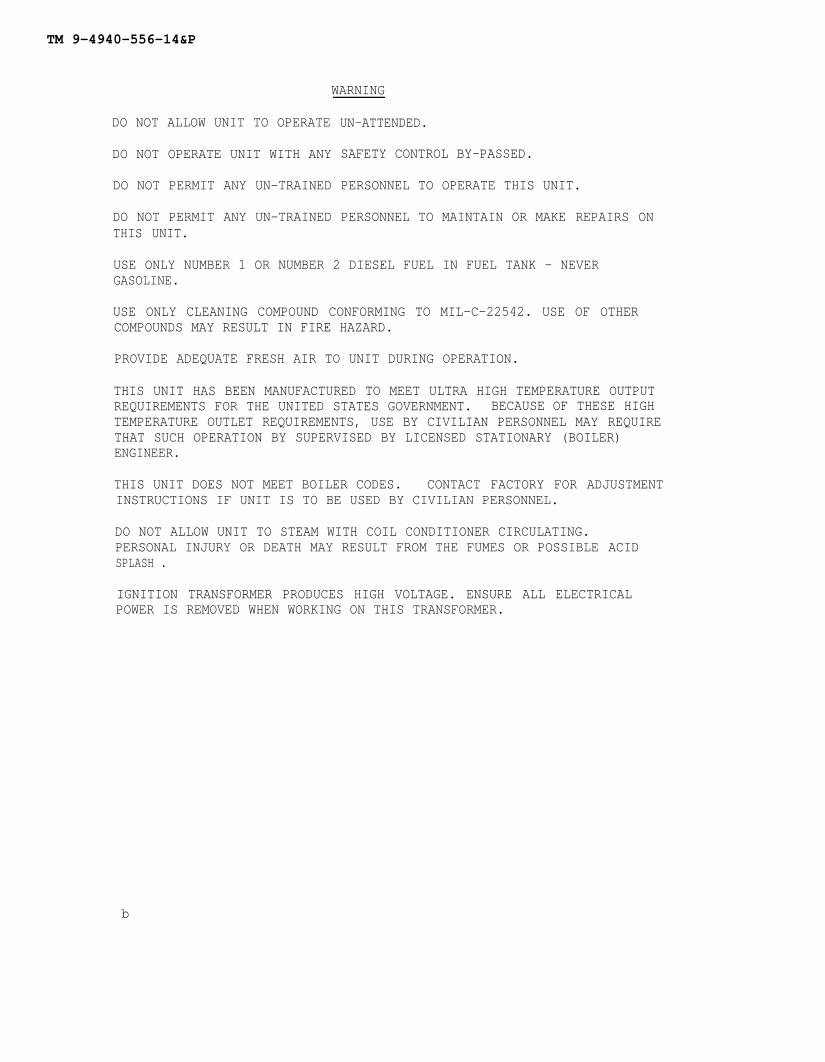
WARNING
DO NOT ALLOW UNIT TO OPERATE
DO NOT OPERATE UNIT WITH ANY
DO NOT PERMIT ANY UN-TRAINED
DO NOT PERMIT ANY UN-TRAINEDTHIS UNIT.
UN-ATTENDED.
SAFETY CONTROL BY-PASSED.
PERSONNEL TO OPERATE THIS UNIT.
PERSONNEL TO MAINTAIN OR MAKE REPAIRS ON
USE ONLY NUMBER 1 OR NUMBER 2 DIESEL FUEL IN FUEL TANK - NEVERGASOLINE.
USE ONLY CLEANING COMPOUND CONFORMING TO MIL-C-22542. USE OF OTHERCOMPOUNDS MAY RESULT IN FIRE HAZARD.
PROVIDE ADEQUATE FRESH AIR TO UNIT DURING OPERATION.
THIS UNIT HAS BEEN MANUFACTURED TO MEET ULTRA HIGH TEMPERATURE OUTPUTREQUIREMENTS FOR THE UNITED STATES GOVERNMENT. BECAUSE OF THESE HIGHTEMPERATURE OUTLET REQUIREMENTS, USE BY CIVILIAN PERSONNEL MAY REQUIRETHAT SUCH OPERATION BY SUPERVISED BY LICENSED STATIONARY (BOILER)ENGINEER.
THIS UNIT DOES NOT MEET BOILER CODES. CONTACT FACTORY FOR ADJUSTMENTINSTRUCTIONS IF UNIT IS TO BE USED BY CIVILIAN PERSONNEL.
DO NOT ALLOW UNIT TO STEAM WITH COIL CONDITIONER CIRCULATING.PERSONAL INJURY OR DEATH MAY RESULT FROM THE FUMES OR POSSIBLE ACIDSPLASH .
IGNITION TRANSFORMER PRODUCES HIGH VOLTAGE. ENSURE ALL ELECTRICALPOWER IS REMOVED WHEN WORKING ON THIS TRANSFORMER.
b
TM 9-4940-556-14&P
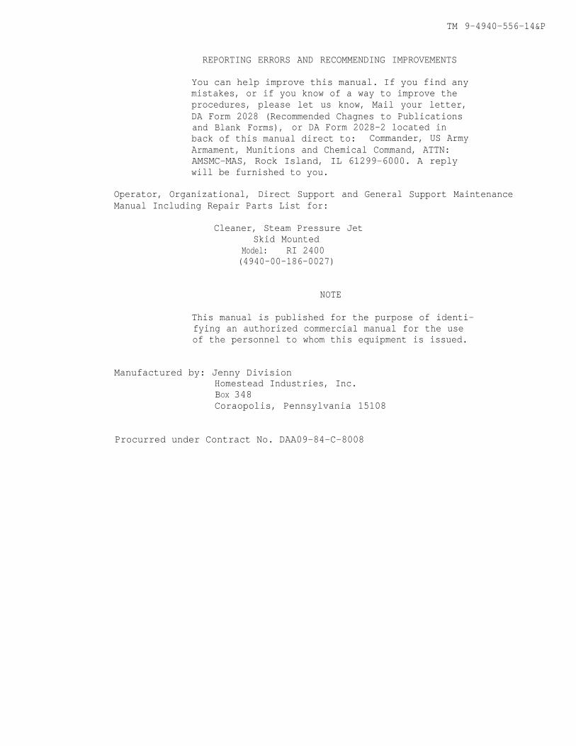
REPORTING ERRORS AND RECOMMENDING IMPROVEMENTS
You can help improve this manual. If you find anymistakes, or if you know of a way to improve theprocedures, please let us know, Mail your letter,DA Form 2028 (Recommended Chagnes to Publicationsand Blank Forms), or DA Form 2028-2 located inback of this manual direct to: Commander, US ArmyArmament, Munitions and Chemical Command, ATTN:AMSMC-MAS, Rock Island, IL 61299-6000. A replywill be furnished to you.
Operator, Organizational, Direct Support and General Support MaintenanceManual Including Repair Parts List for:
Cleaner, Steam Pressure JetSkid Mounted
Model: RI 2400(4940-00-186-0027)
NOTE
This manual is published for the purpose of identi-fying an authorized commercial manual for the useof the personnel to whom this equipment is issued.
Manufactured by: Jenny DivisionHomestead Industries, Inc.BOX 348Coraopolis, Pennsylvania 15108
Procurred under Contract No. DAA09-84-C-8008
TM 9-4940-556-14&P
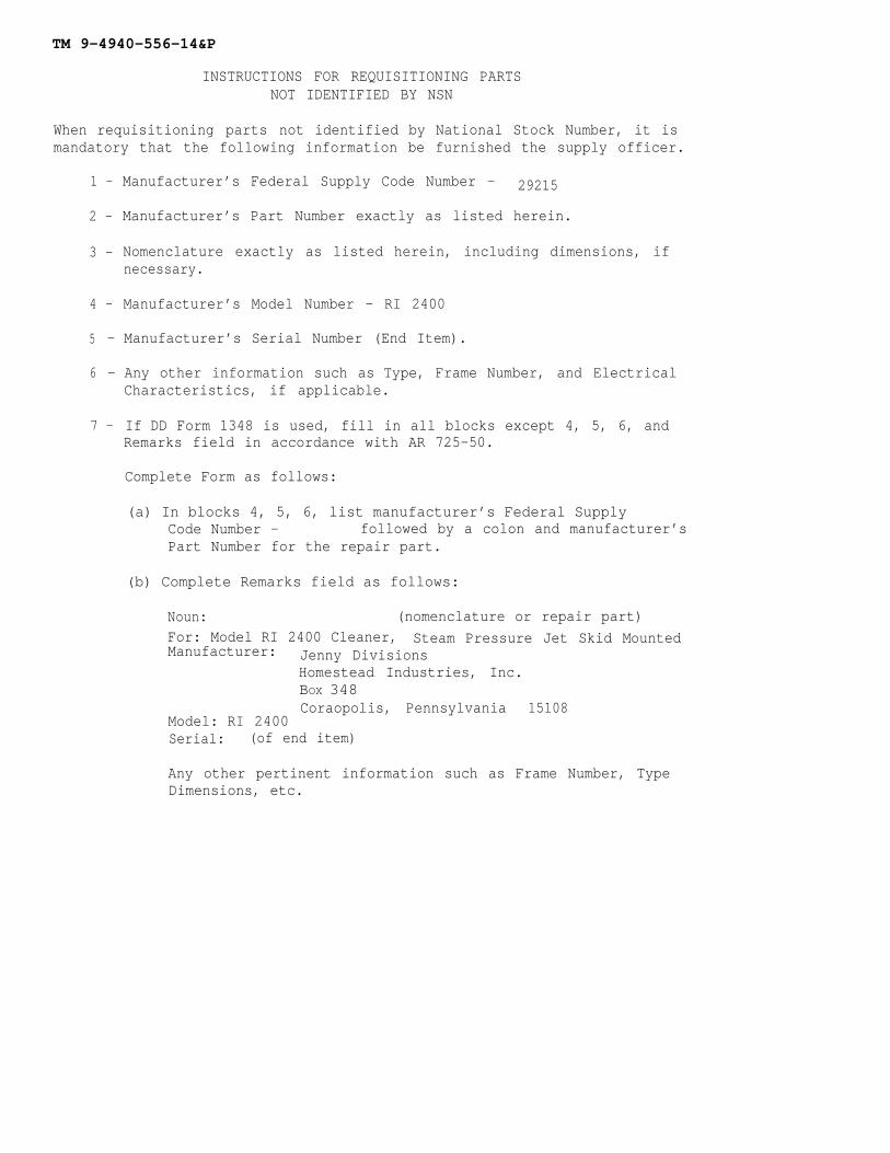
INSTRUCTIONS FOR REQUISITIONING PARTSNOT IDENTIFIED BY NSN
When requisitioning parts not identified by National Stock Number, it ismandatory that the following information be furnished the supply officer.
1 - Manufacturer’s Federal Supply Code Number - 29215
2 - Manufacturer’s Part Number exactly as listed herein.
3 - Nomenclature exactly as listed herein, including dimensions, ifnecessary.
4 - Manufacturer’s Model Number - RI 2400
5 - Manufacturer’s Serial Number (End Item).
6 - Any other information such as Type, Frame Number, and ElectricalCharacteristics, if applicable.
7 - If DD Form 1348 is used, fill in all blocks except 4, 5, 6, andRemarks field in accordance with AR 725-50.
Complete Form as follows:
(a) In blocks 4, 5, 6, list manufacturer’s Federal SupplyCode Number - followed by a colon and manufacturer’sPart Number for the repair part.
(b) Complete Remarks field as follows:
Noun: (nomenclature or repair part)For: Model RI 2400 Cleaner, Steam Pressure Jet Skid MountedManufacturer: Jenny Divisions
Homestead Industries, Inc.BOX 348Coraopolis, Pennsylvania 15108
Model: RI 2400Serial: (of end item)
Any other pertinent information such as Frame Number, TypeDimensions, etc.
TM 9-4940-556-14&P
TABLE OF CONTENTS
INDEX
1.
2.
3.
4.
5
DESCRIPTION
1.1 Nomenclature1.2 Purpose and Function1.3 Dimensions1.4 Power Requirements1.5 Environmental Requirements1.6 Packing List1.7 Items Required For Operation1.8 Storage1.9 Tools
SAFETY PRECAUTIONS/WARNINGS
OPERATION
3.13.23.33.43.53.63.73.83.93.103.113.12
Initial Start Up After StorageStart Unit - STEAM MODEStart Unit - PRESSURE MODEStop UnitChange From 60 Hz. to 50 Hz.Change From 50 Hz. to 60 Hz.Operation Unit From Non-Pressurized Water SourceDescription of Operation and Components - ELECTRICALDescription of Operation and Components - WATER SYSTEMDescription of Operation and Components - SOLUTION SYSTEMDescription of Operation and Components - FUEL SYSTEMDescription of Operation and Components - AIR SYSTEM
ROUTINE MAINTENANCEPROCEDURE/FREQUENCY CHART
4.1 Water System4.2 Fuel System4.3 Solution System4.4 Lubrication4.5 Mechanical
TROUBLE SHOOTING
5.1 Water System5.2 Fuel System5.3 Solution System5.4 Electrical System5.5 Air System
i

TM 9-4940-556-14&P
1 DESCRIPTION
1.1
1.2
1.3
1.4
1.5
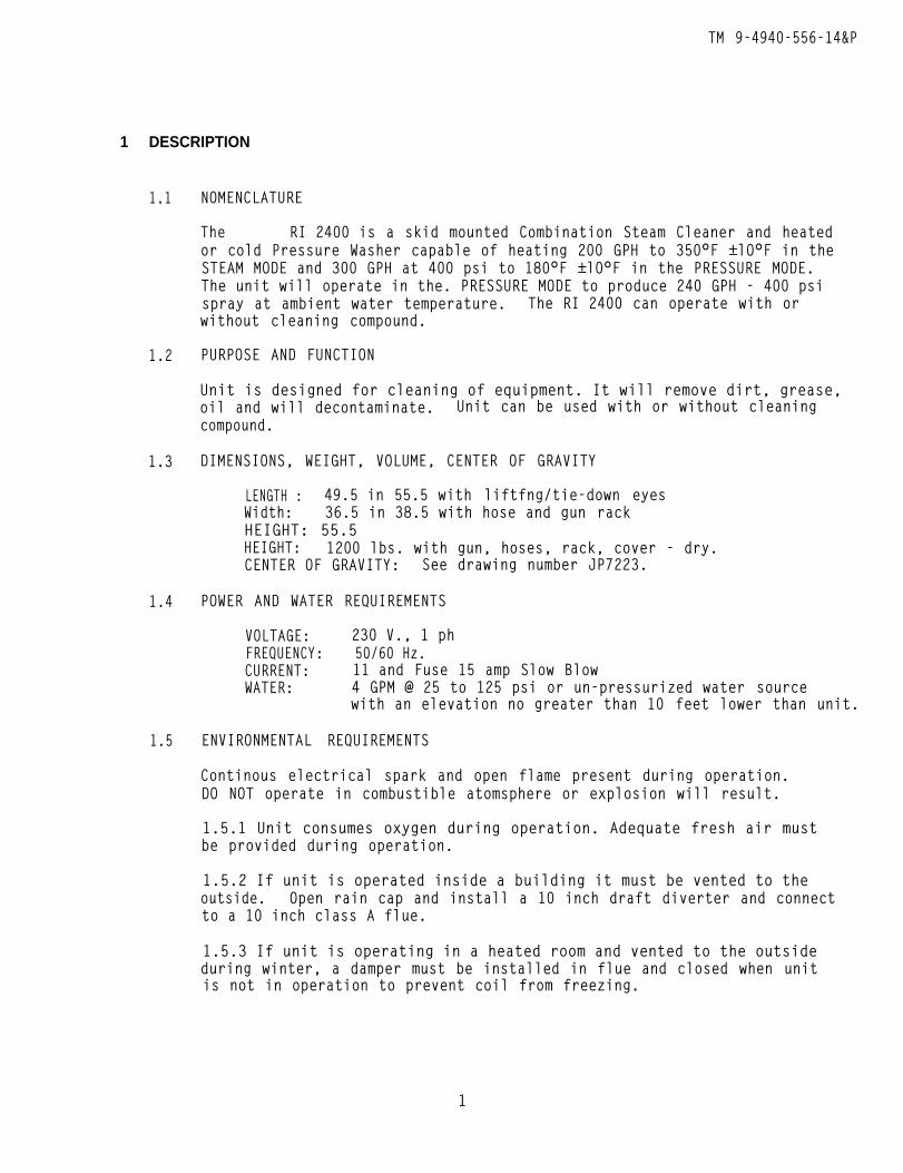
NOMENCLATURE
The RI 2400 is a skid mounted Combination Steam Cleaner and heatedor cold Pressure Washer capable of heating 200 GPH to 350°F ±lO°F in theSTEAM MODE and 300 GPH at 400 psi to 180°F ±lO°F in the PRESSURE MODE.The unit will operate in the. PRESSURE MODE to produce 240 GPH - 400 psispray at ambient water temperature. The RI 2400 can operate with orwithout cleaning compound.
PURPOSE AND FUNCTION
Unit is designed for cleaning of equipment. It will remove dirt, grease,oil and will decontaminate. Unit can be used with or without cleaningcompound.
DIMENSIONS, WEIGHT, VOLUME, CENTER OF GRAVITY
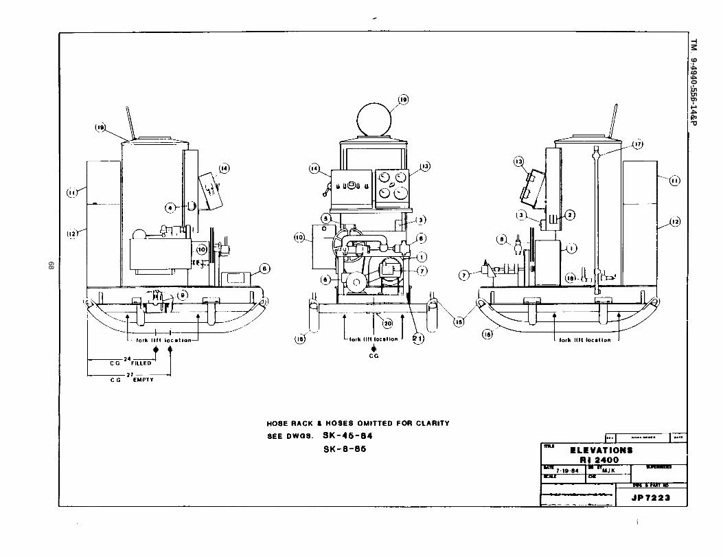
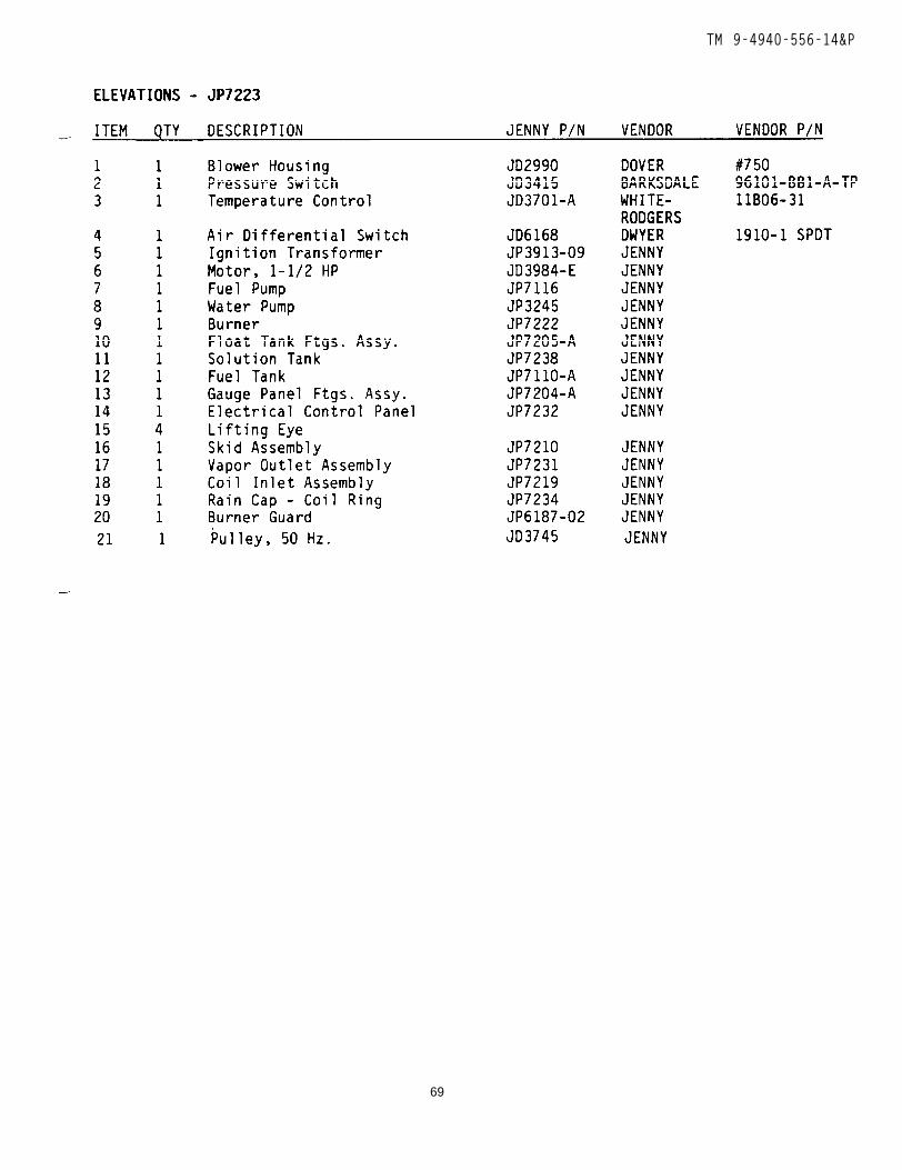
LENGTH : 49.5 in 55.5 with liftfng/tie-down eyesWidth: 36.5 in 38.5 with hose and gun rackHEIGHT: 55.5HEIGHT: 1200 lbs. with gun, hoses, rack, cover - dry.CENTER OF GRAVITY: See drawing number JP7223.
POWER AND WATER REQUIREMENTS
VOLTAGE: 230 V., 1 phFREQUENCY: 50/60 Hz.CURRENT: 11 and Fuse 15 amp Slow BlowWATER: 4 GPM @ 25 to 125 psi or un-pressurized water source
with an elevation no greater than 10 feet lower than unit.
ENVIRONMENTAL REQUIREMENTS
Continous electrical spark and open flame present during operation.DO NOT operate in combustible atomsphere or explosion will result.
1.5.1 Unit consumes oxygen during operation. Adequate fresh air mustbe provided during operation.
1.5.2 If unit is operated inside a building it must be vented to theoutside. Open rain cap and install a 10 inch draft diverter and connectto a 10 inch class A flue.
1.5.3 If unit is operating in a heated room and vented to the outsideduring winter, a damper must be installed in flue and closed when unitis not in operation to prevent coil from freezing.
1
TM 9-4940-556-14&P
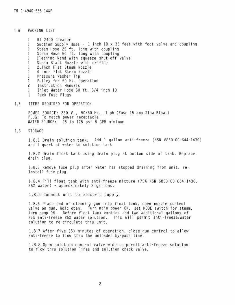
1.6 PACKING LIST
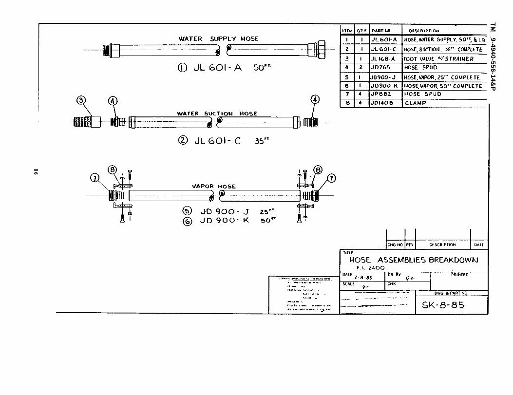
1 RI 2400 Cleaner1 Suction Supply Hose - 1 inch ID x 35 feet with foot valve and coupling1 Steam Hose 25 ft. long with coupling1 Steam Hose 50 ft. long with coupling1 Cleaning Wand with squeeze shut-off valve1 Steam Blast Nozzle with orifice1 2.inch Flat Steam Nozzle1 4 inch Flat Steam Nozzle1 Pressure Washer Tip
Pulley for 50 Hz. operationInstruction Manuals
1 Inlet Water Hose 50 ft. 3/4 inch ID1 Pack Fuse Plugs
1.7 ITEMS REQUIRED FOR OPERATION
POWER SOURCE: 230 V., 50/60 Hz., 1 ph (Fuse 15 amp Slow Blow.)PLUG: To match power receptacleWATER SOURCE: 25 to 125 psi 6 GPM minimum
1.8 STORAGE
1.8.1 Drain solution tank. Add 1 gallon anti-freeze (NSN 6850-00-644-1430)and 1 quart of water to solution tank.
1.8.2 Drain float tank using drain plug at bottom side of tank. Replacedrain plug.
1.8.3 Remove fuse plug after water has stopped draining from unit, re-install fuse plug.
1.8.4 Fill float tank with anti-freeze mixture (75% NSN 6850-00-664-1430,25% water) - approximately 3 gallons.
1.8.5 Connect unit to electric supply.
1.8.6 Place end of cleaning gun into float tank, open nozzle controlvalve on gun, hold open. Turn main power ON, set MODE switch for steam,turn pump ON. Before float tank empties add two additional gallons of75% anti-freeze 25% water solution. This will permit anti-freeze/watersolution to re-circulate thru unit.
1.8.7 After five (5) minutes of operation, close gun control to allowanti-freeze to flow thru the unloader by-pass line.
1.8.8 Open solution control valve wide to permit anti-freeze solutionto flow thru solution lines and solution check valve.
2
TM 9-4940-556-14&P
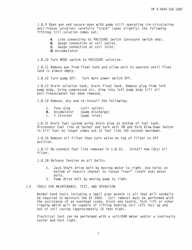
1.8.9 Open gun and secure open with pump still operating (re-circulatinganti-freeze solution) carefully "crack” (open slightly) the followingfittings till solution comes out:
A. Line connecting to PRESSURE switch (pressure switch end).B. Gauge connection at coil outlet.C. Gauge connection at coil inlet.D. Accumulator
1.8.10 Turn MODE switch to PRESSURE solution.
1.8.11 Remove gun from float tank and allow unit to operate until floattank is almost empty.
1.8.12 Turn pump OFF. Turn main power switch OFF.
1.8.13 Drain solution tank, drain float tank. Remove plug from leftpump body, Using compressed air, blow into left pump body till allanti-freeze/water has been removed.
1.8.14 Remove, dry and re-install the following:
A. Fuse plug (coil outlet)Accumulator (pump discharge)
C. Y strainer (pump inlet)
1.8.15 Drain fuel system using drain plug at bottom of fuel tank.Disconnect fuel line at burner and turn unit ON and hold Blow-Down buttonin till fuel no longer comes out of fuel line (60 seconds maximum).
1.8.16 Remove oil filter then turn valve on top of filter to OFFposition.
1.8.17 Re-connect fuel line removed in 1.8.15. Install new (dry) oilfilter.
1.8.18 Release Tension on all belts:
A. Jack Shaft drive belt by moving motor to right. Use holes onbottom of chassis channel to loosen “rear” (shaft end) motorbolts.
B. Pump drive belt by moving pump to
1.9 TOOLS FOR MAINTENANCE, TEST, AND OPERATION
right.
Normal hand tools including a small pipe wrench is all that will normallybe required to maintain the RI 2400. Coil removal must be performed withthe assistance of an overhead crane, block and tackle, fork lift or otherrigging which will be capable of lifting heating coil (275 lbs) up andout of coil casing (approximately 10 feet high).
Electrical test can be performed with a volt/OHM meter and/or a continuitytester and test light.
3
TM 9-4940-556-14&P
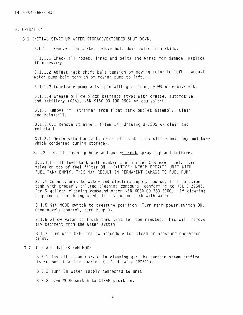
3. OPERATION
3.1 INITIAL START-UP AFTER STORAGE/EXTENDED SHUT DOWN.
3.1.1. Remove from crate, remove hold down bolts from skids.
3.1.1.1 Check all hoses, lines and belts and wires for damage. Replaceif necessary.
3.1.1.2 Adjust jack shaft belt tension by movingwater pump belt tension by moving pump to left.
3.1.1.3 Lubricate pump wrist pin with gear lube,
motor to left. Adjust
G090 or equivalent.
3.1.1.4 Grease pillow block bearings (two) with grease, automotiveand artillery (GAA), NSN 9150-00-190-0904 or equivalent.
3.1.2 Remove “Y” strainer from float tank outlet assembly. Cleanand reinstall.
3.1.2.0.1 Remove strainer, (item 14, drawing JP7205-A) clean andreinstall.
3.1.2.1 Drain solution tank, drain oil tank (this will remove any moisturewhich condensed during storage).
3.1.3 Install cleaning hose and gun without spray tip and oriface.
3.1.3.1 Fill fuel tank with number 1 or number 2 diesel fuel. Turnvalve on top of fuel filter ON. CAUTION: NEVER OPERATE UNIT WITHFUEL TANK EMPTY. THIS MAY RESULT IN PERMANENT DAMAGE TO FUEL PUMP.
3.1.4 Connect unit to water and electric supply source, fill solutiontank with properly diluted cleaning compound, conforming to MIL-C-22542.For 5 gallons cleaning compound order NSN 6850-00-753-5000. If cleaningcompound is not being used, fill solution tank with water.
3.1.5 Set MODE switch to pressure position. Turn main power switch ON.Open nozzle control, turn pump ON.
3.1.6 Allow water to flush thru unit for ten minutes. This will removeany sediment from the water system.
3.1.7 Turn unit OFF, follow procedure for steam or pressure operationbelow.
3.2 TO START UNIT-STEAM MODE
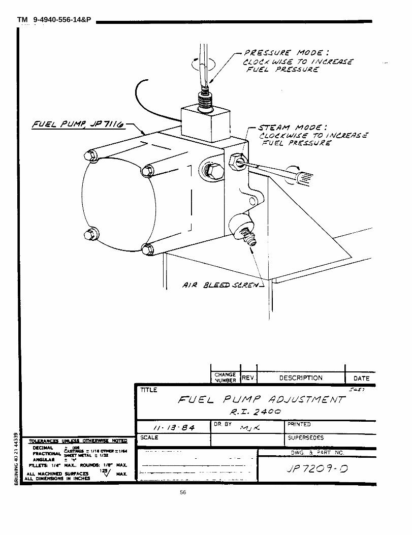
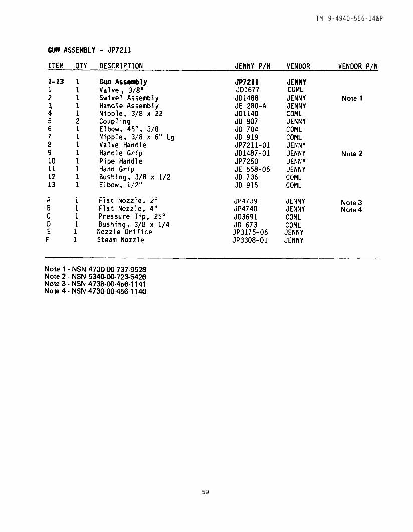
3.2.1 Install steam nozzleis screwed into the nozzle
3.2.2 Turn ON water supply
in cleaning gun, be certain steam orifice(ref. drawing JP7211).
connected to unit.
3.2.3 Turn MODE switch to STEAM position.
4
TM 9-4940-556-14&P
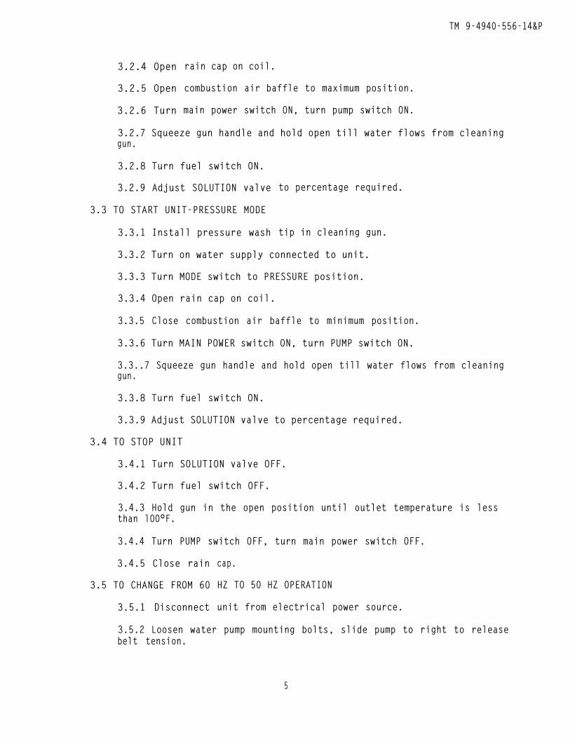
3.2.4 Open
3.2.5 Open
3.2.6 Turn
rain cap on coil.
combustion air baffle to maximum position.
main power switch ON, turn pump switch ON.
3.2.7 Squeeze gun handle and hold open till water flows from cleaninggun.
3.2.8 Turn fuel switch ON.
3.2.9 Adjust SOLUTION valve
3.3 TO START UNIT-PRESSURE MODE
3.3.1 Install pressure wash
to percentage required.
tip in cleaning gun.
3.3.2 Turn on water supply connected to unit.
3.3.3 Turn MODE switch to PRESSURE position.
3.3.4 Open rain cap on coil.
3.3.5 Close combustion air baffle to minimum position.
3.3.6 Turn MAIN POWER switch ON, turn PUMP switch ON.
3.3..7 Squeeze gun handle and hold open till water flows from cleaninggun.
3.3.8 Turn fuel switch ON.
3.3.9 Adjust SOLUTION valve to percentage required.
3.4 TO STOP UNIT
3.4.1 Turn SOLUTION valve OFF.
3.4.2 Turn fuel switch OFF.
3.4.3 Hold gun in the open position until outlet temperature is lessthan lOO°F.
3.4.4 Turn PUMP switch OFF, turn main power switch OFF.
3.4.5 Close rain
3.5 TO CHANGE FROM 60
3.5.1 Disconnect
cap.
HZ TO 50 HZ OPERATION
unit from electrical power source.
3.5.2 Loosen water pump mounting bolts, slide pump to right to releasebelt tension.
5
TM 9-4940-556-14&P
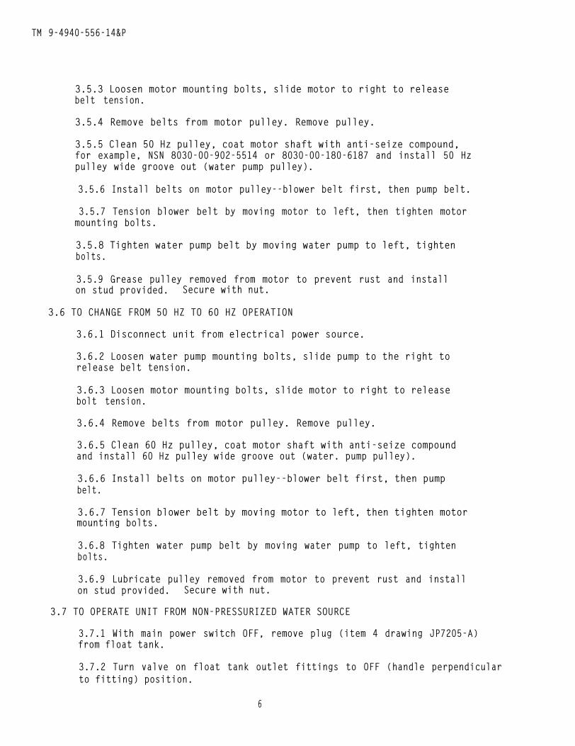
3.5.3 Loosen motor mounting bolts, slide motor to right to releasebelt tension.
3.5.4 Remove belts from motor pulley. Remove pulley.
3.5.5 Clean 50 Hz pulley, coat motor shaft with anti-seize compound,for example, NSN 8030-00-902-5514 or 8030-00-180-6187 and install 50 Hzpulley wide groove out (water pump pulley).
3.5.6 Install belts on motor pulley--blower belt first, then pump belt.
3.5.7 Tension blower belt by moving motor to left, then tighten motormounting bolts.
3.5.8 Tighten water pump belt by moving water pump to left, tightenbolts.
3.5.9 Grease pulley removed from motor to prevent rust and installon stud provided. Secure with nut.
3.6 TO CHANGE FROM 50 HZ TO 60 HZ OPERATION
3.6.1 Disconnect unit from electrical power source.
3.6.2 Loosen water pump mounting bolts, slide pump to the right torelease belt tension.
3.6.3 Loosen motor mounting bolts, slide motor to right to releasebolt tension.
3.6.4 Remove belts from motor pulley. Remove pulley.
3.6.5 Clean 60 Hz pulley, coat motor shaft with anti-seize compoundand install 60 Hz pulley wide groove out (water. pump pulley).
3.6.6 Install belts on motor pulley--blower belt first, then pumpbelt.
3.6.7 Tension blower belt by moving motor to left, then tighten motormounting bolts.
3.6.8 Tighten water pump belt by moving water pump to left, tightenbolts.
3.6.9 Lubricate pulley removed from motor to prevent rust and installon stud provided. Secure with nut.
3.7 TO OPERATE UNIT FROM NON-PRESSURIZED WATER SOURCE
3.7.1 With main power switch OFF, remove plug (item 4 drawing JP7205-A)from float tank.
3.7.2 Turn valve on float tank outlet fittings to OFF (handle perpendicularto fitting) position.
6
TM 9-4940-556-14&P
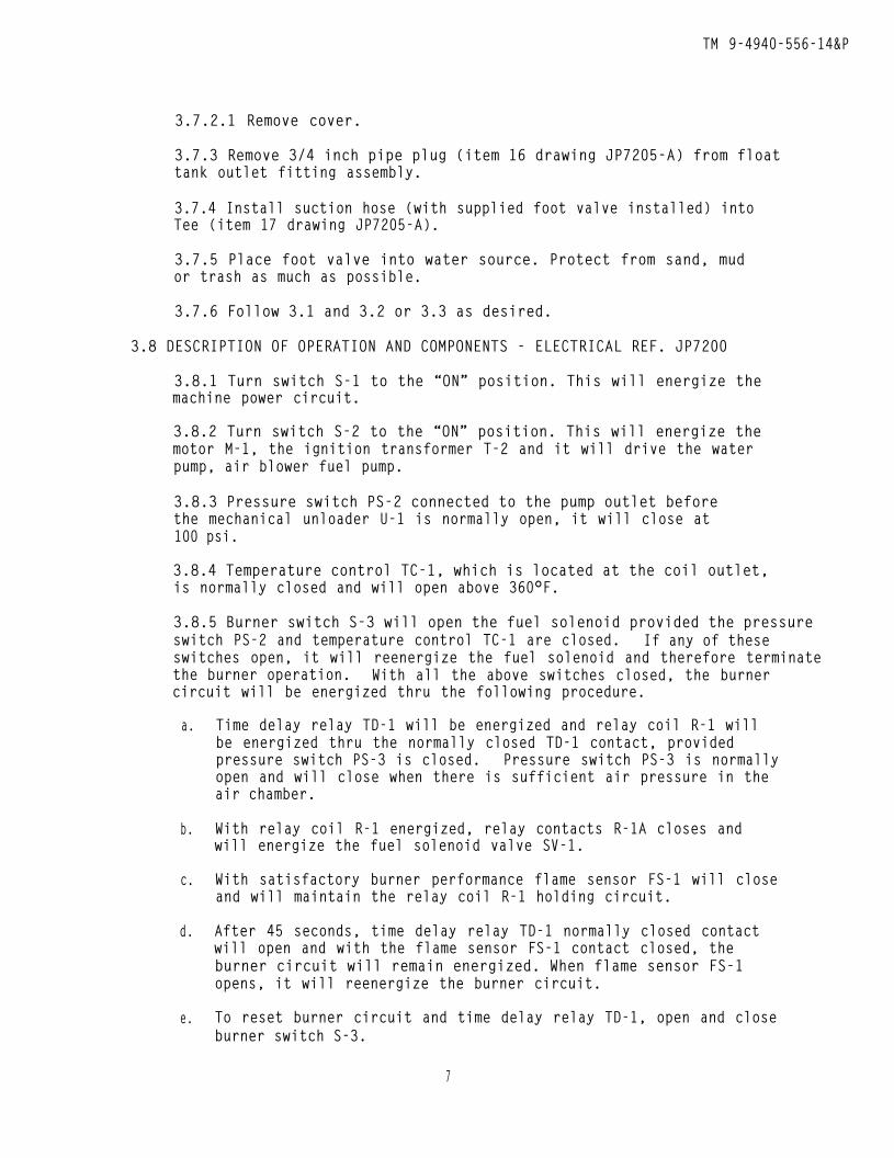
3.7.2.1 Remove cover.
3.7.3 Remove 3/4 inch pipe plug (item 16 drawing JP7205-A) from floattank outlet fitting assembly.
3.7.4 Install suction hose (with supplied foot valve installed) intoTee (item 17 drawing JP7205-A).
3.7.5 Place foot valve into water source. Protect from sand, mudor trash as much as possible.
3.7.6 Follow 3.1 and 3.2 or 3.3 as desired.
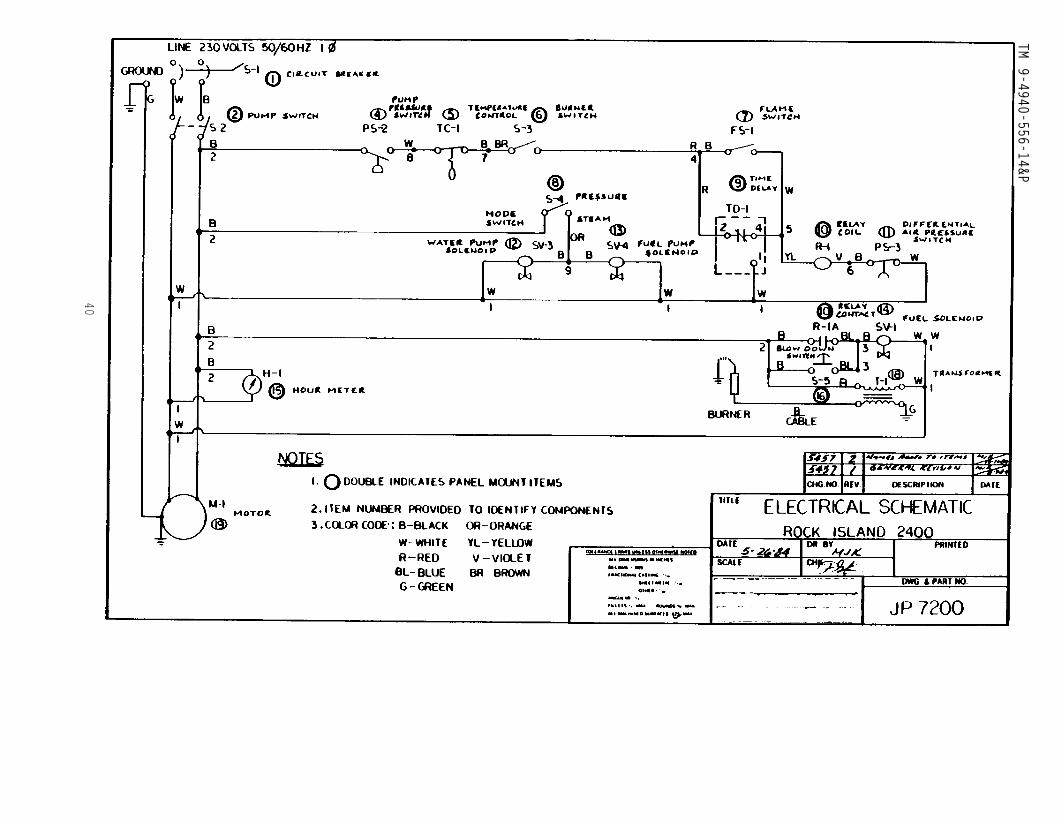
3.8 DESCRIPTION OF OPERATION AND COMPONENTS - ELECTRICAL REF. JP7200
3.8.1 Turn switch S-1 to the “ON” position. This will energize themachine power circuit.
3.8.2 Turn switch S-2 to the “ON” position. This will energize themotor M-1, the ignition transformer T-2 and it will drive the waterpump, air blower fuel pump.
3.8.3 Pressure switch PS-2 connected to the pump outlet beforethe mechanical unloader U-1 is normally open, it will close at100 psi.
3.8.4 Temperature control TC-1, which is located at the coil outlet,is normally closed and will open above 360°F.
3.8.5 Burner switch S-3 will open the fuel solenoid provided the pressureswitch PS-2 and temperature control TC-1 are closed. If any of theseswitches open, it will reenergize the fuel solenoid and therefore terminatethe burner operation. With all the above switches closed, the burnercircuit will be energized thru the following procedure.
a. Time delay relay TD-1 will be energized and relay coil R-1 willbe energized thru the normally closed TD-1 contact, providedpressure switch PS-3 is closed. Pressure switch PS-3 is normallyopen and will close when there is sufficient air pressure in theair chamber.
b. With relay coil R-1 energized, relay contacts R-1A closes andwill energize the fuel solenoid valve SV-1.
c. With satisfactory burner performance flame sensor FS-1 will closeand will maintain the relay coil R-1 holding circuit.
d. After 45 seconds, time delay relay TD-1 normally closed contactwill open and with the flame sensor FS-1 contact closed, theburner circuit will remain energized. When flame sensor FS-1opens, it will reenergize the burner circuit.
e. To reset burner circuit and time delay relay TD-1, open and closeburner switch S-3.
7
TM 9-4940-556-14&P
3.8.6 Mode switch S-4 is to select either the pressure wash or steammode of operation. This switch energizes and deenergizes, solenoidvalve SV-3 for water bypass and changes fuel pump outlet pressure.
3.8.7 Blow down switch S-5 will be used in conjunction with valveV-5 for blow down operation. This switch enables the operator toenergize the burner circuit.
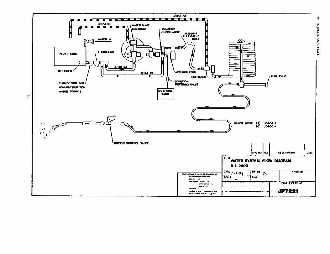
3.9 DESCRIPTION OF OPERATION AND COMPONENTS-WATER SYSTEM - REF.DRAWING JP7221
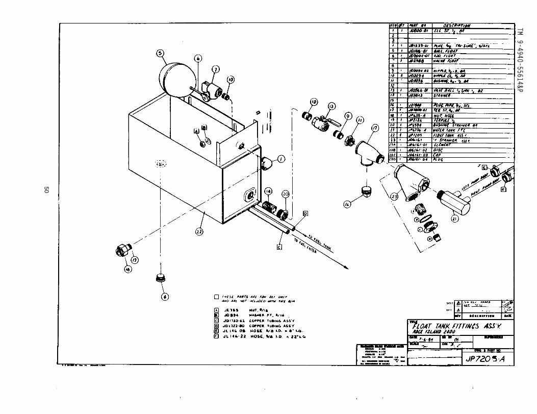
3.9.1 (Reference drawing JP7205-A) Water enters the unit thru a hoseferrule into the float tank. Water is drawn from the float tank througha strainer in the float tank, then thru a float tank SHUT-OFF valve anda “WYE” strainer to the pump where its pressure is increased substantially.
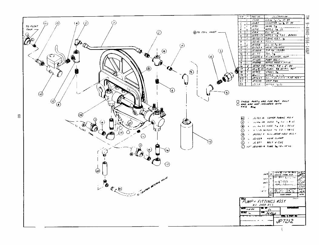
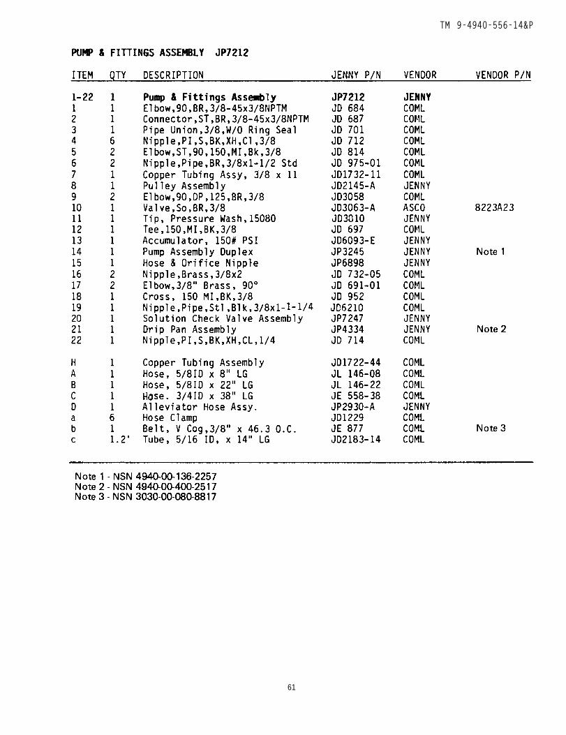
3.9.2 (Reference drawing JP7212) The pump is equipped with an accumulator,a device which absorbs hydraulic pulsations in the water system. Thehose which connects the pump outlet with the coil inlet fittings isan alleviator hose - a. special hose which also absorbs hydraulic pulsations.On the RI-2400 a solenoid valve is used on the left output side ofthe pump to return a fixed volume of water back to the float tank. Thevolume of water “dumped” in this fashion is determined by an orificeplaced in the return line. The switch used to control this dumpingis called the MODE SWITCH (S-4). In its pressure position, it permitsthe full pumped volume of water to pass through the COIL: when thisswitch is on the STEAM position, a measured volume of water returnsto the float tank thus reducing the volume of water pumped thruthe heating coil.
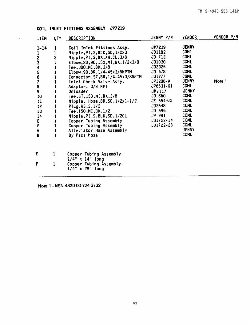
3.9.3 (Reference drawing JP7219) The discharge line from the pumpconnects to the inlet of the heating coil. Because the RI-2400 isequipped with nozzle control, an unloader, a pressure actuated valve,is also connected to the outlet of the pump. The unloader divertsthe water from the pump back to the float tank when the cleaning gunis closed.
3.9.4 At the coil inlet there is a pressure drain/relief valve which willprotect the coil and pump from a blocked cleaning gun. A coil inletpressure gauge is also connected to the inlet fittings assembly.
3.9.5 Water passes thru the coil, where it is heated, and into thecoil outlet fittings assembly which includes an outlet pressure gauge,outlet temperature gauge and the sensing bulb for the temperaturecontrol (TC-1).
3.9.6 The hose and cleaning gun are attached to the coil outlet fittingassembly. The cleaning gun can be fitted with either a pressure washtip or a steam nozzle and orifice assembly. The tip and orifice restrictthe flow of water thru the system and cause the unit to operate atthe correct pressure with the appropriate temperature rise. The cleaninggun handle is also equipped with a valve which will turn the cleaningspray on or off.
8
TM 9-4940-556-14&P
3.10 DESCRIPTION OF OPERATION AND COMPONENTS - SOLUTION SYSTEM
3.10.1 Cleaning solution is drawn from the stainless steel solutiontank through the panel mounted solution valve, then into the righthand water pump body, through a ball check valve. This check valveprevents water from being pumped back into the solution tank.
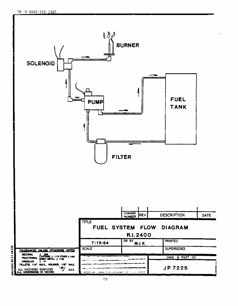
3.11 DESCRIPTION OF OPERATION AND COMPONENTS - FUEL SYSTEM- REF.DRAWING JP7225
3.11.1 Number 1 or 2 diesel fuel, is placed in the fuel tank. Fuelis drawn out of tank thru a fuel filter by the fuel pump. The fuelfilter holder is equipped with a shut-off valve. The dual pressure,shaft driven pump has a adjustable by-pass which diverts part of itsoutput back to the top of the fuel tank. Its high and low pressureoutput is selected by the MODE SWITCH.
3.11.2 The main discharge line from the fuel pump goes through a fuelsolenoid valve (SV-1) to the burner. This solenoid will SHUT-OFF fuelto the burner when cleaning gun is closed. Fuel solenoid is activatedby a pressure switch which is connected to the water system at thecoil inlet.
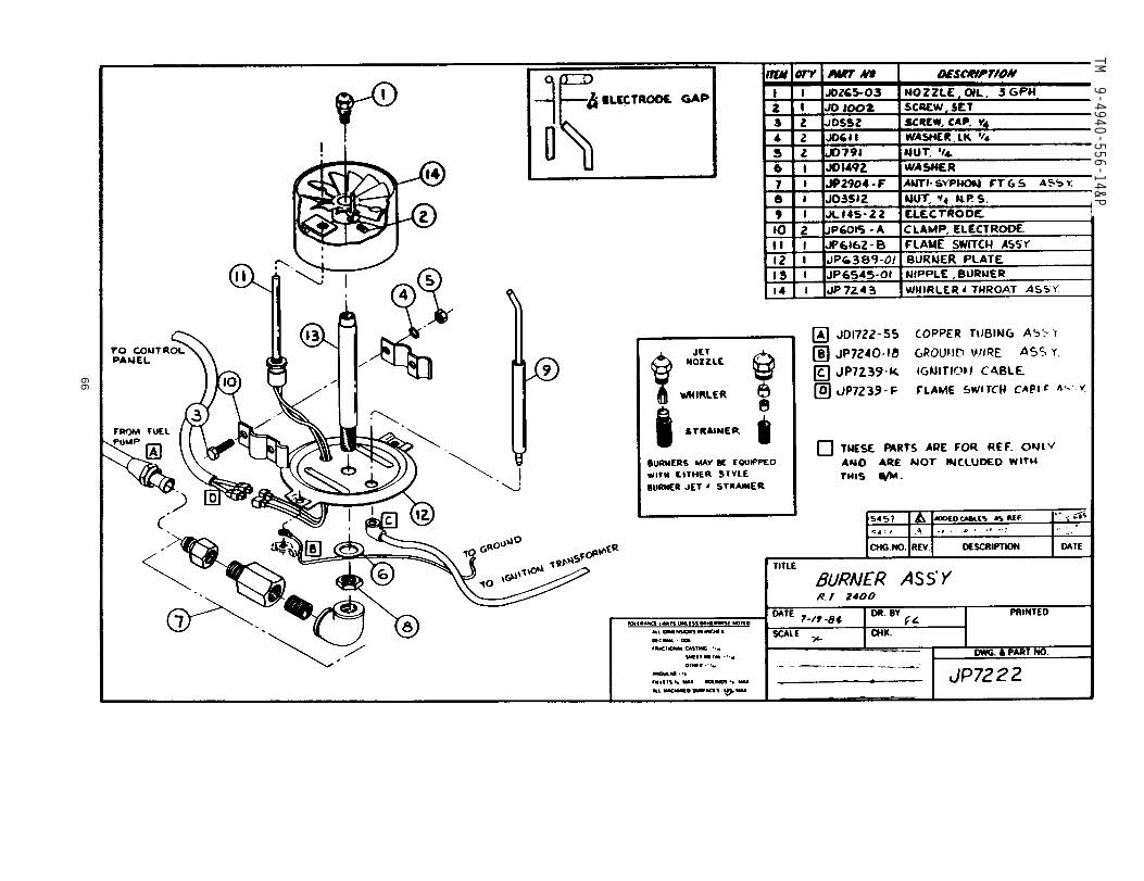
3.11.3 The burner is equipped with a 90 degree fuel jet and strainerassembly. The fuel jet size along with fuel pump output pressuredetermines how much fuel is burned and the strainer minimizes jet cloggingdue to dirt in the fuel.
3.12 DESCRIPTION OF OPERATION AND COMPONENTS - AIR SYSTEM
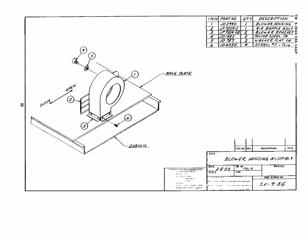
3.12.1 The squirrel cage fan is mounted on one end of a belt drivenjack shaft and draws air into unit. The blower is equipped with anadjustable baffle to regulate the air supply if necessary.
3.12.2 Air is blown into a chamber under the coil casing and is forcedthru the air whirler and through the burner assembly. The oxygen inthe air supports the combustion of the oil and carries hot gasses throughthe heating coil thus transferring heat energy to the water passingthrough the coil.
3.12.2 A pressure switch (PS-3) will interrupt the flow of fuel tothe burner if the fan would fail.
9
TM 9-4940-556-14&P
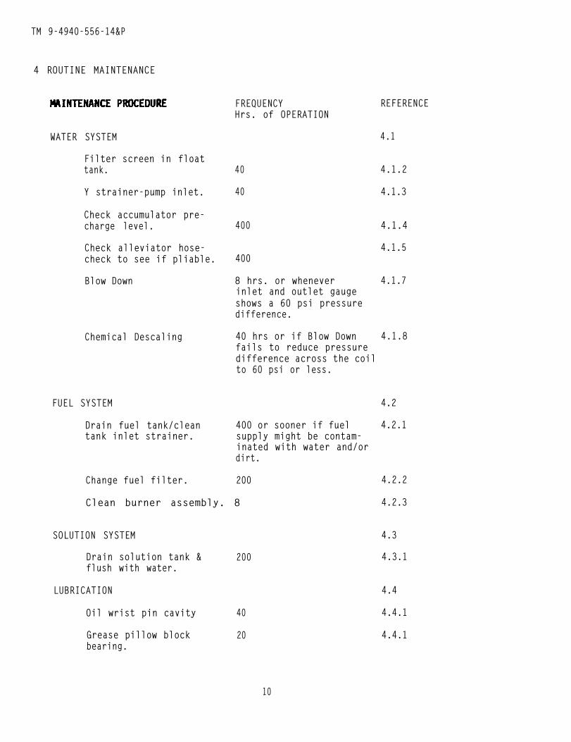
4 ROUTINE MAINTENANCE
WATER SYSTEM
Filter screen in floattank.
Y strainer-pump inlet.
Check accumulator pre-charge level.
Check alleviator hose-check to see if pliable.
Blow Down
Chemical Descaling
FREQUENCYHrs. of OPERATION
40
40
400
400
8 hrs. or wheneverinlet and outlet gaugeshows a 60 psi pressuredifference.
REFERENCE
4.1
4.1.2
4.1.3
4.1.4
4.1.5
4.1.7
40 hrs or if Blow Down 4.1.8fails to reduce pressuredifference across the coilto 60 psi or less.
FUEL SYSTEM 4.2
Drain fuel tank/clean 400 or sooner if fuel 4.2.1tank inlet strainer. supply might be contam-
inated with water and/ordirt.
Change fuel filter. 200
Clean burner assembly. 8
SOLUTION SYSTEM
Drain solution tank & 200flush with water.
LUBRICATION
Oil wrist pin cavity
Grease pillow blockbearing.
40
20
4.2.2
4.2.3
4.3
4.3.1
4.4
4.4.1
4.4.1
10
TM 9-4940-556-14&P
MAINTENANCE PROCEDURE
MECHANICAL
Tension belt
Hoses
Nuts and bolts andset screws.
FREQUENCYHrs. of OPERATION
DAILY
40
200
REFERENCE
4.5
4.5.1
4.5.2
4.5.3
4.1.2 Filter screen in float tank (reference drawing JP7205-A) the filterscreen or strainer (item 14) can be removed for cleaning by reaching underfloat tank baffle (item 23) and pulling it from the brass bushing (item20). After cleaning, push strainer back into bushing.
4.1.3 Y strainer (reference drawing JP7205-A) (item 15) can be cleaned byremoving cap and sliding strainer out of the fitting. Clean strainer andre-install.
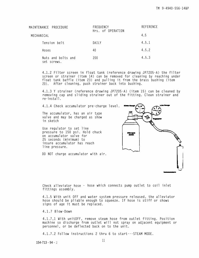
4.1.4 Check accumulator pre-charge level.
The accumulator, has an air typevalve and may be charged as showin sketch
Use regulator to set linepressure to 150 psi. Hold chuckon accumulator valve for25 seconds (minimum) toinsure accumulator has reachline pressure.
DO NOT charge accumulator with air.
Check alleviator hose - hose which connects pump outlet to coil inletfittings assembly.
4.1.5 With unit OFF and water system pressure released, the alleviatorhose should be pliable enough to squeeze. If hose is stiff or showssigns of age it must be replaced.
4.1.7 Blow-Down
4.1.7,1 With unitOFF, remove steam hose from outlet fitting. Positionmachine so discharge from outlet will not spray on adjacent equipment orpersonnel, or be deflected back on to the unit.
4.1.7.2 Follow instructions 2 thru 6 to start---STEAM MODE.
11154-713 - 94 - 2
TM 9-4940-556-14&P
4.1.7.3 Depress BLOW-DOWN button and hold in.
4.1.7.4 After outlet temperature reads 250°F, lift float rod (interruptingthe flow of water through the unit) and hold for 1 minute after tank empties.
4.1.7.5 Release float rod and BLOW-DOWN button.
4.1.7.6 Allow unit to run till coil outlet temperature is 100°F ---- shutunit OFF.
4.1.7.7 Install steam hose in machine outlet.
4.1.8 Descaling Instructions.
4.1.8.1 Mineral deposits in the coil and coil outlet fittings assembly arethe result of the affects of heat on un-dissolved solids in the water used.These deposits must be periodically removed to prevent the coil from beingclogged.
4.1.8.2 Chemical descaling (deliming) should be attempted only after BLOW-DOWN procedure has failed to reduce the difference in coil inlet and outletpressure to less than 60 psi.
4.1.8.3 Sulfamic Acid, NSN 6850-01-174-9548, comes in a 10 pound containerand contains all inhibitors necessary to protect the metal parts of theequipment on which it is to be used.
4.1.8.4 Before the descaling procedures are started, read and follow all“DANGER”, “WARNING”, “CAUTION” and “FIRST AID STATEMENTS”.
4.1.8.4.1 “DANGER”
Inhibited coil descaling powder contains “Sulfamic Acid” and is a poison anda corrosive chemical.
4.1.8.4.2 “DANGER”
“Sulfamic Acid” should not be handled unless the user is properly clothed, in-cluding rubber boots, rubber apron, rubber gloves and a full face shield. Theuser should read and understand the following procedure, along with the pre-cautions printed on the acid container. “Failure to do so could result insevere or possible fatal injury to personnel.”
4.1.8.4.3 “DANGER”
Operations must be done in a well ventilated area. Carbon dioxide vapors arereleased during this procedure. “Injury to personnel may result if properventilation is not provided.”
12
TM 9-4940-556-14&P
4.1.8.4.4 “WARNING”
Do not handle sulfamic acid bare-handed. Moisture in the skin will activatethe acid causing burns.
4.1.8.4.5 “FIRST AID PROCEDURES”
Sulfamic acid and its solutions can cause eye burns and may irritate the skin.
In cases of eye contact, immediately flush the eyes with plenty of waterfor at least 15 minutes. Call a physician.
For skin contact, flush with plenty of water.
For ingestion of sulfamic acid, immediately drink large amounts of water,“Do not Induce Vomiting”. Call a physician.
4.1.8.4.6 Read the instructions on the sulfamic acid container before use.
4.1.8.4.7 “CAUTION”
Only authorized personel who have read and understand this procedure shouldbe permitted to perform this function.
4.1.8.5 Turn water supply ON.
4.1.8.6 Remove pressure wash tip and/or steam nozzle and orifice from cleaninggun . Place in float tank.
4.1.8.7 Clean “Y” strainer in float tank outlet assembly (item 15, drawingJP7205-A). Re-install.
4.1.8.7.1 Clean strainer in float tank (item 14, drawing JP7205-A).
4.1.8.8 Turn solution control valve to the OFF position (fully clockwise).Operate the unit in the PRESSURE MODE with the burner OFF for five minutes oruntil all cleaning compound has been purged from unit.
4.1.8.9 Turn water supply to the unit OFF and operate unit (FUEL OFF -PRESSURE MODE) nozzle control open - until after four (4) inches of waterremains in the float tank. Place end of cleaning gun into float tank. Thiswill cause water to re-circulate through unit. Secure gun (nozzle open) inthis position. If water does not circulate, add water till it does.
4.1.8.10 To avoid nuisance clogging of the water reservoir strainer, it isrecommended that a dished filter of steel or copper window screening be in-serted on top of the water supply tank. The cleaning gun should be positionedto permit recirculation of water from the water supply tank through thecleaner, hose, cleaning gun, and back into the water supply tank through dishedfilter screen.
13
TM 9-4940-556-14&P
4.1.8.11 With the pump switch “ON” and the burner switch"OFF”, allow thewater to start recirculating through the cleaning gun and into the waterreservoir.
4.1.8.11.1 “WARNING”
Do not allow the unit to produce steam with the cleaning solution circulatingas injury to personnel may result from fumes or hot acid splash.
4.1.8.12 Pour approximately two pounds of sulfamic acid into the water reser-voir tank. Turn on the water pump to circulate the solution. After thirtyminutes, turn off the water pump and check the color of the solution. If ayellow color is present, the sulfamic acid is spent. If scale is still presentin the heating coil, repeat the above adding 2 pounds of sulfamic acid at 30minute intervals until the solution remains a reddish color for thirty minutes.During the above procedure cycle the burner (turn on and off) just long enoughfor the cleaning gun to feel warm but not hot. It may be necessary to stopcleaner from time to time to remove scale accumulation from dished filterscreen and/or to pump excess solution into another container to avoid over-flowing water supply tank. This excess solution must be subsequently neutral-ized using sodium hydroxide mixture outlined below. Turn off the water circu-lating system.
4.1.8.12.1 NOTE: Carbon dioxide is released as long as scale and sulfamicacid are present. After the scale is dissolved, gases cease to form and thecolor of the solution remains a reddish color.
4.1.8.13 Before draining the solution from the steam cleaner, it should bechecked and neutralized as necessary. If a yellow color is present, thesolution is spent and can be flushed into a sanitary sewer with equal parts ofwater, If the solution is a reddish color, it should be neutralized by addingSodium Hydroxide (NSN 6310-00-270-8177, 13 oz). Turn on the water pump andslowly add enough sodium hydroxide to just change the color of the solution toa yellow color. When the solution just changes from red to yellow, it can bedisposed of as outlined above.
4.1.8.14 STOP UNIT. Remove end of cleaning gun from float tank and placedischarge end of gun in a drain or other location for disposal of solution.
4.1.8.15 Turn ON water to unit. Start unit and open nozzle controlto flush water thru unit for ten minutes.
4.1.8.15.1 Flush with water any areas of unit splashed with acid.
4.1.8.16 Remove tips/nozzle from float tank.
4.1.8.17 Remove hose from coil outlet to allow sediment collected to flushout. Re-install hose.
14
TM 9-4940-556-14&P
4.1.8.18 Install pressure tip or steam nozzle in unit, set MODE switch andadjust air baffle appropriately.
4.1.8.19 Turn pump switch on, check coil inlet pressure gage with coil outletpressure gage, if pressure differential is more than specified in the instruc-tion manual, the coil may need a second treatment.
4.1.8.20 Fill solution tank with correctly diluted cleaning compound.
4.1.8.21 Unit is now ready for normal operation.
4.1.8.22 If a second treatment fails to reduce the pressure differentialbelow the pressure specified in the instruction manual, the coil may need tobe removed and soaked in a solution of sulfamic acid.
4.1.8.23 Coil soaking is an alternative to avoid the high cost of requisi-tioning a new coil. This can be performed by removing the coil from thecleaner and soaking the coil in a sulfamic acid solution of five pounds ofsulfamic acid to five gallons of water. Enough solution should be mixed tocompletely cover the coil in a suitable container. Check the coil solutionperiodically for color. If the color of the solution is yellow, add two morepounds of sulfamic acid to the coil solution. Repeat as necessary until thesolution stays a reddish color for at least 2 hours. This indicates verylittle scale is present.
4.1.8.24 Before draining the solution from the coil container, it should bechecked and neutralized. Check the color of the solution, if the color isyellow, the solution can be disposed of into a sanitary sewer with equal partsof water. If the solution is red in color, add sodium hydroxide slowly untilthe solution just begins to change from red to yellow. When this changeoccurs, the solution may be flushed into a sanitary sewer with equal parts ofwater. Rinse the coil with water for five minutes and pour the neutralizedsolution down the drain, Reinstall the coil and test for leaks.
14.1

TM 9-4940-556-14&P
THIS PAGE LEFT INTENTIONALLY BLANK.
14.2

TM 9-4940-558-14&P
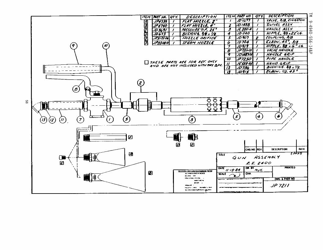
4.2 FUEL SYSTEM
4.2.1 Drain and clean fuel tank (ref. drawing JP711O) this procedurewill waste a minimum of fuel if the fuel tank is almost empty priorto proceeding.
4.2.1.1 Follow 3.4 - to stop unit, remove drain plug (item 1, drawingJP711O) and permit fuel to drain completely form tank.
4.2.1.2 Clean fuel tank inlet strainer by removing cap and wipingstrainer with a rag.
4.2.1.3 Replace drain plug (item 1, drawing JP711O) fill fuel tank withnumber 1 or number 2 diesel fuel.
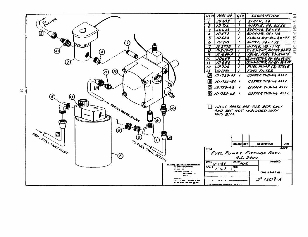
4.2.2 Change fuel filter with unit OFF, Turn OFF fuel at filter holder(item 10, drawing JP7209-A).
4.2.2.1 Un-screw filter cartridge and discard. Lubricate gasket on topof new cartridge with oil and hand tighten.
4.2.2.2 Turn fuel ON at fuel filter holder (item 10, drawing JP7209-A).
4.2.3 Clean burner assembly.
4.2.3.1 With unit OFF, turn fuel filter valve to OFF position (item 10,drawing JP7209-A). DISCONNECT: Burner protector/skid plate, from chassis,high voltage lead from burner electrode two (2) wires to flame sensor(FS-1), and fuel line.
4.2.3.3 Wire brush electrodes - DO NOT wire brush burner jet or allow anydirt to enter orifice. Gap electrode to 3/23 inch.
4.2.3.8 Reversing procedure in 4.2.3.2 and making sure round” wire fromhigh voltage transformer is connected to one of the two (2) burner mountingstuds, tighten wing nuts to secure burner in place.
4.2.3.9 Reconnect; two (2) wires to flame sensor, fuel line, high voltagelead and re-install the burner protector shield.
4.2.3.10 Turn fuel filter valve to ON (item 10, drawing JP7209-A).
4.3 SOLUTION SYSTEM
4.3.1 Drain solution tank and flush with water. - With unit OFF, removedrain plug from side of tank.
4.3.1.1 After solution has drained from tank, remove tank cap and insertwater hose into tank - push to the bottom. Turn ON water and flush forfive (5) minutes.
4.3.2 Turn OFF water, remove hose and install drain plug removed in 4.3.1.Fill solution with compound conforming to MIL-C-22542.
4.3.2.1 If cleaning compound is not used, fill solution tank with water.
15

TM 9-4940-556-14&P
THIS PAGE LEFT INTENTIONALLY BLANK
16
TM 9-4940-556-14&P
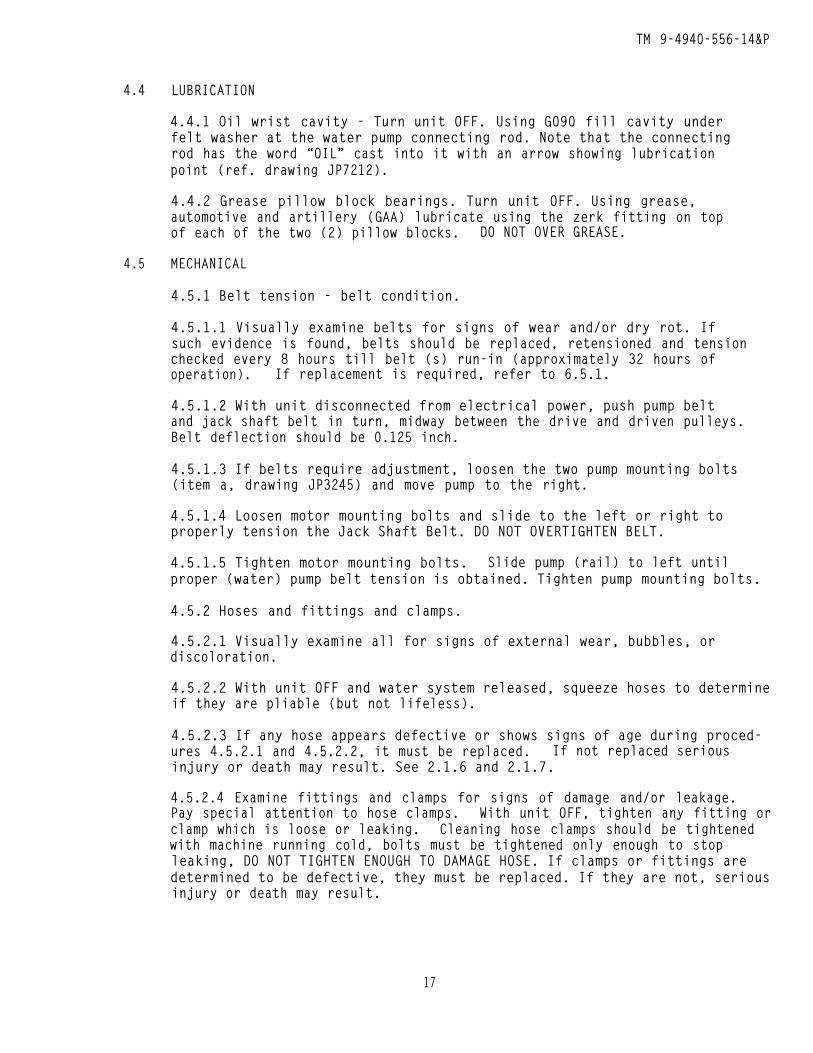
4.4 LUBRICATION
4.4.1 Oil wrist cavity - Turn unit OFF. Using G090 fill cavity underfelt washer at the water pump connecting rod. Note that the connectingrod has the word “OIL” cast into it with an arrow showing lubricationpoint (ref. drawing JP7212).
4.4.2 Grease pillow block bearings. Turn unit OFF. Using grease,automotive and artillery (GAA) lubricate using the zerk fitting on topof each of the two (2) pillow blocks. DO NOT OVER GREASE.
4.5 MECHANICAL
4.5.1 Belt tension - belt condition.
4.5.1.1 Visually examine belts for signs of wear and/or dry rot. Ifsuch evidence is found, belts should be replaced, retensioned and tensionchecked every 8 hours till belt (s) run-in (approximately 32 hours ofoperation). If replacement is required, refer to 6.5.1.
4.5.1.2 With unit disconnected from electrical power, push pump beltand jack shaft belt in turn, midway between the drive and driven pulleys.Belt deflection should be 0.125 inch.
4.5.1.3 If belts require adjustment, loosen the two pump mounting bolts(item a, drawing JP3245) and move pump to the right.
4.5.1.4 Loosen motor mounting bolts and slide to the left or right toproperly tension the Jack Shaft Belt. DO NOT OVERTIGHTEN BELT.
4.5.1.5 Tighten motor mounting bolts. Slide pump (rail) to left untilproper (water) pump belt tension is obtained. Tighten pump mounting bolts.
4.5.2 Hoses and fittings and clamps.
4.5.2.1 Visually examine all for signs of external wear, bubbles, ordiscoloration.
4.5.2.2 With unit OFF and water system released, squeeze hoses to determineif they are pliable (but not lifeless).
4.5.2.3 If any hose appears defective or shows signs of age during proced-ures 4.5.2.1 and 4.5.2.2, it must be replaced. If not replaced seriousinjury or death may result. See 2.1.6 and 2.1.7.
4.5.2.4 Examine fittings and clamps for signs of damage and/or leakage.Pay special attention to hose clamps. With unit OFF, tighten any fitting orclamp which is loose or leaking. Cleaning hose clamps should be tightenedwith machine running cold, bolts must be tightened only enough to stopleaking, DO NOT TIGHTEN ENOUGH TO DAMAGE HOSE. If clamps or fittings aredetermined to be defective, they must be replaced. If they are not, seriousinjury or death may result.
17
TM 9-4940-556-14&P
4.5.3 Nuts, bolts, set screws.
4.5.3.1 With unit disconnected from electrical power, check all visiblenuts and bolts to be certain none are loose.
4.5.3.2 With allen wrench, check set screws on pump pulley, Jack Shaftpulley, fan hub and pillow block bearings. Pillow block bearings have2 set screws. Tighten as necessary.
18
TM 9-4940-566-14&P
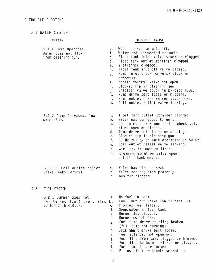
5 TROUBLE SHOOTING
5.1 WATER SYSTEM
SYSTEM
5.1.1 Pump Operates.Water does not flowfrom cleaning gun.
5.1.2 Pump Operates, lowwater flow.
a.b.
d.e.f.g.
h.i.j.k.l.m.
a.b.c.
d.e.f.g.h.i.
5.1.2.1 Coil outlet relief a.valve leaks (drips). b.
c.
5.2 FUEL SYSTEM
5.2.1 Burner does not a.ignite (no fuel) (ref. also b.to 5.4.3, 5.4.0.1).
d.e.f.g.
h.i.j.k.l.m.
POSSIBLE CAUSE
Water source to unit off.Water not connected to unit.Float tank inlet valve stuck or clogged.Float tank outlet strainer clogged.Y strainer clogged.Float tank shut-off valve closed.Pump inlet check valve(s) stuck ordefective.Nozzle control valve not open.Blocked tip in cleaning gun.Unloader valve stuck in by-pass MODE.Pump drive belt loose or missing.Pump outlet check valves stuck open.Coil outlet relief valve leaking.
Float tank outlet strainer clogged.Water not connected to unit.One inlet and/or one outlet check valvestuck open or closed.Pump drive belt loose or missing.Blocked tip in cleaning gun.60 Hz pulley on unit operating on 50 Hz.Coil outlet relief valve leaking.Air leak in suction lines.Cleaning solution valve open;solution tank empty.
Valve has dirt on seat.Valve not adjusted properly.Gun tip clogged
No fuel in tank.Fuel Shut-off valve (on filter) OFF.Clogged fuel filter.Soap/water in fuel tank.Burner jet clogged.Burner switch OFF.Fuel pump drive coupling broken(fuel pump not turning).Jack Shaft drive belt loose.Fuel solenoid not opening.Fuel line from tank plugged or kinked.Fuel line to burner kinked or plugged.Fuel pump is air locked.Pillow block or blocks seized up.
19
TM 9-4940-556-14&P
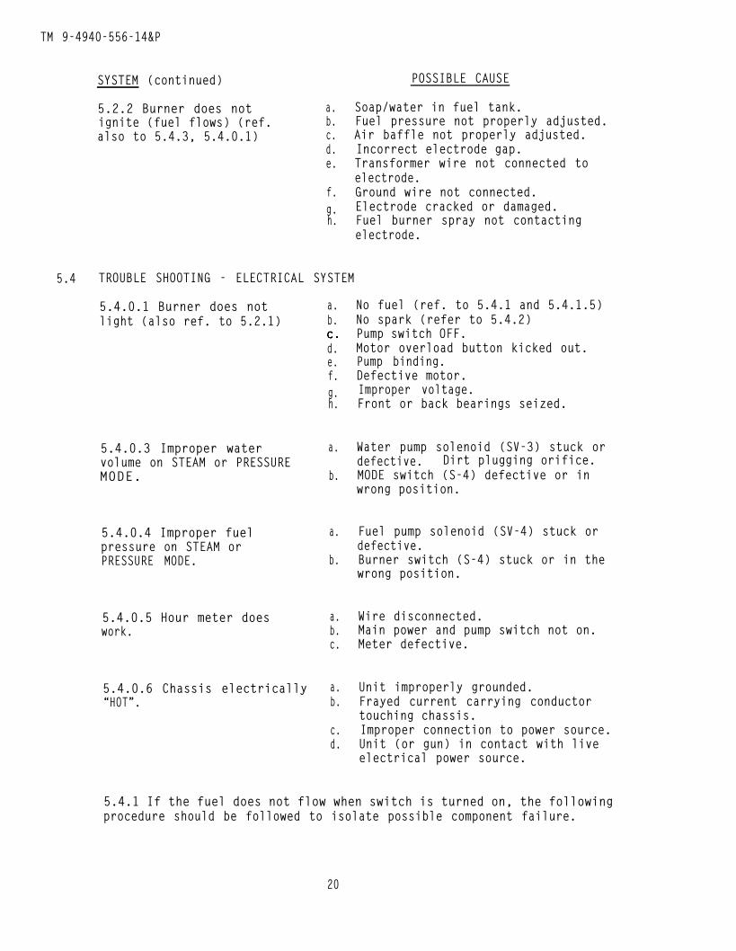
SYSTEM (continued) POSSIBLE CAUSE
5.2.2 Burner does not a.ignite (fuel flows) (ref. b.also to 5.4.3, 5.4.0.1) c.
d.e.
f.g.h.
Soap/water in fuel tank.Fuel pressure not properly adjusted.Air baffle not properly adjusted.Incorrect electrode gap.Transformer wire not connected toelectrode.Ground wire not connected.Electrode cracked or damaged.Fuel burner spray not contactingelectrode.
5.4 TROUBLE SHOOTING - ELECTRICAL SYSTEM
5.4.0.1 Burner does notlight (also ref. to 5.2.1)
5.4.0.3 Improper watervolume on STEAM or PRESSUREMODE.
5.4.0.4 Improper fuelpressure on STEAM orPRESSURE MODE.
5.4.0.5 Hour meter doeswork.
5.4.0.6 Chassis electrically“HOT”.
a.b.
d.e.f.g.h.
a.
b.
a.
b.
a.b.c.
a.b.
c.d.
No fuel (ref. to 5.4.1 and 5.4.1.5)No spark (refer to 5.4.2)Pump switch OFF.Motor overload button kicked out.Pump binding.Defective motor.Improper voltage.Front or back bearings seized.
Water pump solenoid (SV-3) stuck ordefective. Dirt plugging orifice.MODE switch (S-4) defective or inwrong position.
Fuel pump solenoid (SV-4) stuck ordefective.Burner switch (S-4) stuck or in thewrong position.
Wire disconnected.Main power and pump switch not on.Meter defective.
Unit improperly grounded.Frayed current carrying conductortouching chassis.Improper connection to power source.Unit (or gun) in contact with liveelectrical power source.
5.4.1 If the fuel does not flow when switch is turned on, the followingprocedure should be followed to isolate possible component failure.
20

TM 9-4940-556-14&P
WARNING _ THESE PROCEDURES REQUIRE TESTS TO BE PERFORMEDWITH PROTECTIVE COVERS OPEN OR REMOVED. THEY MUST BEPERFORMED BY PERSONNEL TRAINED TO MAKE ELECTRICAL REPAIRS.
5.4.1.1 Secure cleaning gun and have personnel hold in the “ON” position.Start unit following 3.3 with fuel on, place multi-meter across terminal1 and 3. If 220 V is present, fuel solenoid is receiving power and iseither defective or stuck.
5.4.1.1.1 To determine if coil is defective, remove coil from valve andinsert screwdriver into coil. Turn burner switch ON. If coil is workingscrewdriver will be held in coil (no magnetic field present) and 5.4.1.1indicated voltage to coil, coil is defective (or wire to coil is open).
5.4.1.2 If 220 V. is notmalfunctioning.
5.4.1.3 WARNING - DO NOTCONTROLS BYPASSED--INJURY
indicated, one of the safety switches may be
OPERATE THE UNIT WITH ANY OF THE SAFETY SWITCHES/OR DEATH MAY RESULT. ONCE FAULT IS ISOLATED,
REPLACE SWITCH AND/OR RECTIFY CONDITION WHICH CAUSED SWITCH TO OPERATE.
5.4.1.4 In order to determine which safety switch is functioning/mal-functioning follow the procedure below IN THE ORDER WRITTEN.
Tip in gun.Water connected to unit/power connected to unit.Main power ON.Pump switch ON.Burner switch ON.
Operating voltage (220 vac) should be obtained between the following terminalstrip locations. If voltage is not obtained, check function of the componentlisted at right. In order to quickly isolate problem, make voltage checkin the order listed.
Terminal
1 - 2 S-2 Pump Switch1 - 8 PS-2 Pressure Switch1 - 7 TC-1 Thermo Control1 - 4 S-3 Burner Switch1 - 5 FS-1 Flame Switch2 - 6 PS-3 Air Differential
Turn MODE Switch to STEAM
1 - 9 S-4 Mode Switch
21
TM 9-4940-558-14&P
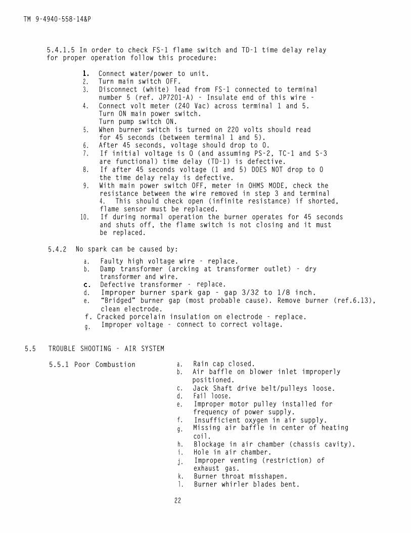
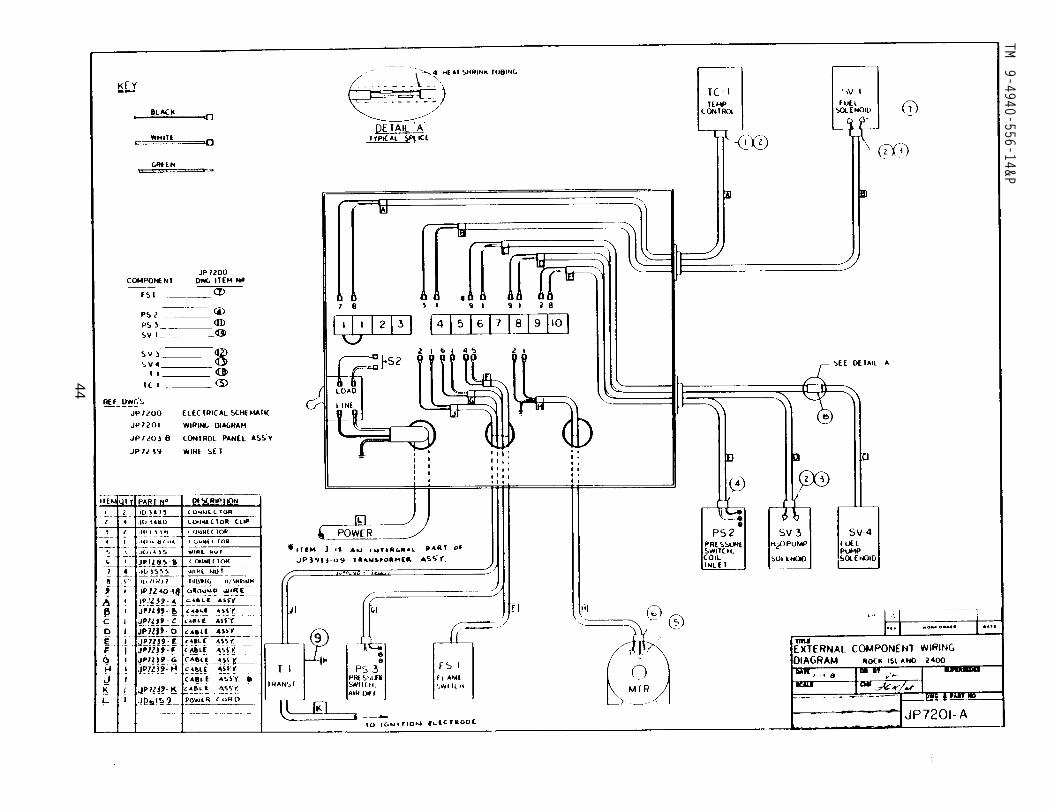
5.4.1.5 In order to check FS-1 flame switch and TD-1 time delay relayfor proper operation follow this procedure:
5.4.2
2.3.
4.
5.
6.7.
8.
9.
10.
Connect water/power to unit.Turn main switch OFF.Disconnect (white) lead from FS-1 connected to terminalnumber 5 (ref. JP7201-A) - Insulate end of this wire -Connect volt meter (240 Vac) across terminal 1 and 5.Turn ON main power switch.Turn pump switch ON.When burner switch is turned on 220 volts should readfor 45 seconds (between terminal 1 and 5).After 45 seconds, voltage should drop to O.If initial voltage is O (and assuming PS-2, TC-1 and S-3are functional) time delay (TD-1) is defective.If after 45 seconds voltage (1 and 5) DOES NOT drop to Othe time delay relay is defective.With main power switch OFF, meter in OHMS MODE, check theresistance between the wire removed in step 3 and terminal4. This should check open (infinite resistance) if shorted,flame sensor must be replaced.If during normal operation the burner operates for 45 secondsand shuts off, the flame switch is not closing and it mustbe replaced.
No spark can be caused by:
a. Faulty high voltage wire - replace.b. Damp transformer (arcking at transformer outlet) - dry
transformer and wire.Defective transformer - replace.
d. Improper burner spark gap - gap 3/32 to 1/8 inch.e. “Bridged” burner gap (most probable cause). Remove burner (ref.6.13),
clean electrode.f. Cracked porcelain insulation on electrode - replace.g. Improper voltage - connect to correct voltage.
5.5 TROUBLE SHOOTING - AIR SYSTEM
5.5.1 Poor Combustion a.b.
c.d.e.
f.g.
h.i.j.
k.l.
Rain cap closed.Air baffle on blower inlet improperlypositioned.Jack Shaft drive belt/pulleys loose.Fail loose.Improper motor pulley installed forfrequency of power supply.Insufficient oxygen in air supply.Missing air baffle in center of heatingcoil.Blockage in air chamber (chassis cavity).Hole in air chamber.Improper venting (restriction) ofexhaust gas.Burner throat misshapen.Burner whirler blades bent.
22
TM 9-4940-556-14&P
6 REPAIR
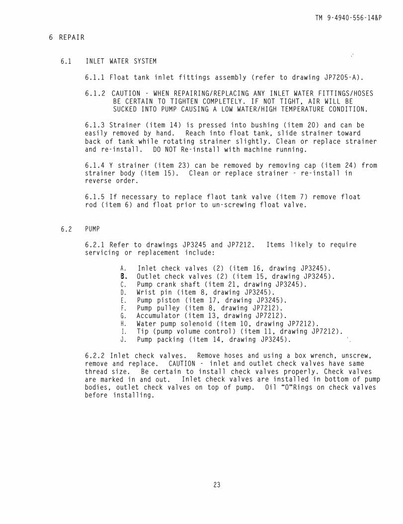
6.1 INLET WATER SYSTEM.-
6.1.1 Float tank inlet fittings assembly (refer to drawing JP7205-A).
6.1.2 CAUTION - WHEN REPAIRING/REPLACING ANY INLET WATER FITTINGS/HOSESBE CERTAIN TO TIGHTEN COMPLETELY. IF NOT TIGHT, AIR WILL BESUCKED INTO PUMP CAUSING A LOW WATER/HIGH TEMPERATURE CONDITION.
6.1.3 Strainer (item 14) is pressed into bushing (item 20) and can beeasily removed by hand. Reach into float tank, slide strainer towardback of tank while rotating strainer slightly. Clean or replace strainerand re-install. DO NOT Re-install with machine running.
6.1.4 Y strainer (item 23) can be removed by removing cap (item 24) fromstrainer body (item 15). Clean or replace strainer - re-install inreverse order.
6.1.5 If necessary to replace flaot tank valve (item 7) remove floatrod (item 6) and float prior to un-screwing float valve.
6.2 PUMP
6.2.1 Refer to drawings JP3245 and JP7212. Items likely to requireservicing or replacement include:
A.
C.D.E.F.G.H.I.J.
Inlet check valves (2) (item 16, drawing JP3245).Outlet check valves (2) (item 15, drawing JP3245).Pump crank shaft (item 21, drawing JP3245).Wrist pin (item 8, drawing JP3245).Pump piston (item 17, drawing JP3245).Pump pulley (item 8, drawing JP7212).Accumulator (item 13, drawing JP7212).Water pump solenoid (item 10, drawing JP7212).Tip (pump volume control) (item 11, drawing JP7212).Pump packing (item 14, drawing JP3245). ‘ .
6.2.2 Inlet check valves. Remove hoses and using a box wrench, unscrew,remove and replace. CAUTION - inlet and outlet check valves have samethread size. Be certain to install check valves properly. Check valvesare marked in and out. Inlet check valves are installed in bottom of pumpbodies, outlet check valves on top of pump. Oil “O"Rings on check valvesbefore installing.
23
TM 9-4940-556-14&P
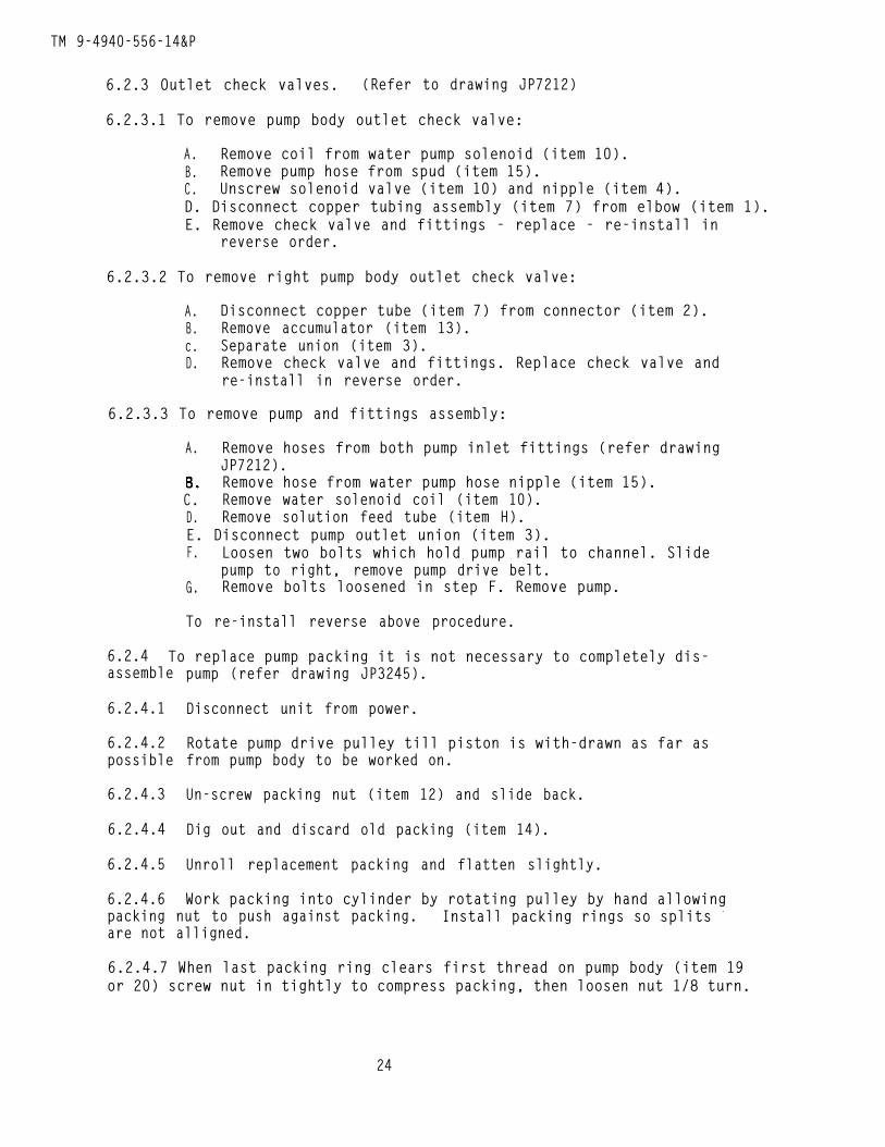
6.2.3 Outlet check valves. (Refer to drawing JP7212)
6.2.3.1 To remove pump body outlet check valve:
A. Remove coil from water pump solenoid (item 10).B. Remove pump hose from spud (item 15).C. Unscrew solenoid valve (item 10) and nipple (item 4).D. Disconnect copper tubing assembly (item 7) from elbow (item 1).E. Remove check valve and fittings - replace - re-install in
reverse order.
6.2.3.2 To remove right pump body outlet check valve:
A. Disconnect copper tube (item 7) from connector (item 2).B. Remove accumulator (item 13).c. Separate union (item 3).D. Remove check valve and fittings. Replace check valve and
re-install in reverse order.
6.2.3.3 To remove pump and fittings assembly:
A. Remove hoses from both pump inlet fittings (refer drawingJP7212).Remove hose from water pump hose nipple (item 15).
C. Remove water solenoid coil (item 10).D. Remove solution feed tube (item H).E. Disconnect pump outlet union (item 3).F. Loosen two bolts which hold pump rail to channel. Slide
pump to right, remove pump drive belt.G. Remove bolts loosened in step F. Remove pump.
To re-install reverse above procedure.
6.2.4 To replace pump packing it is not necessary to completely dis-assemble
6.2.4.1
6.2.4.2possible
6.2.4.3
6.2.4.4
6.2.4.5
6.2.4.6
pump (refer drawing JP3245).
Disconnect unit from power.
Rotate pump drive pulley till piston is with-drawn as far asfrom pump body to be worked on.
Un-screw packing nut (item 12) and slide back.
Dig out and discard old packing (item 14).
Unroll replacement packing and flatten slightly.
Work packing into cylinder by rotating pulley by hand allowingpacking nut to push against packing. Install packing rings so splits -
are not alligned.
6.2.4.7 When last packing ring clears first thread on pump body (item 19or 20) screw nut in tightly to compress packing, then loosen nut 1/8 turn.
24
TM 9-4940-556-14&P
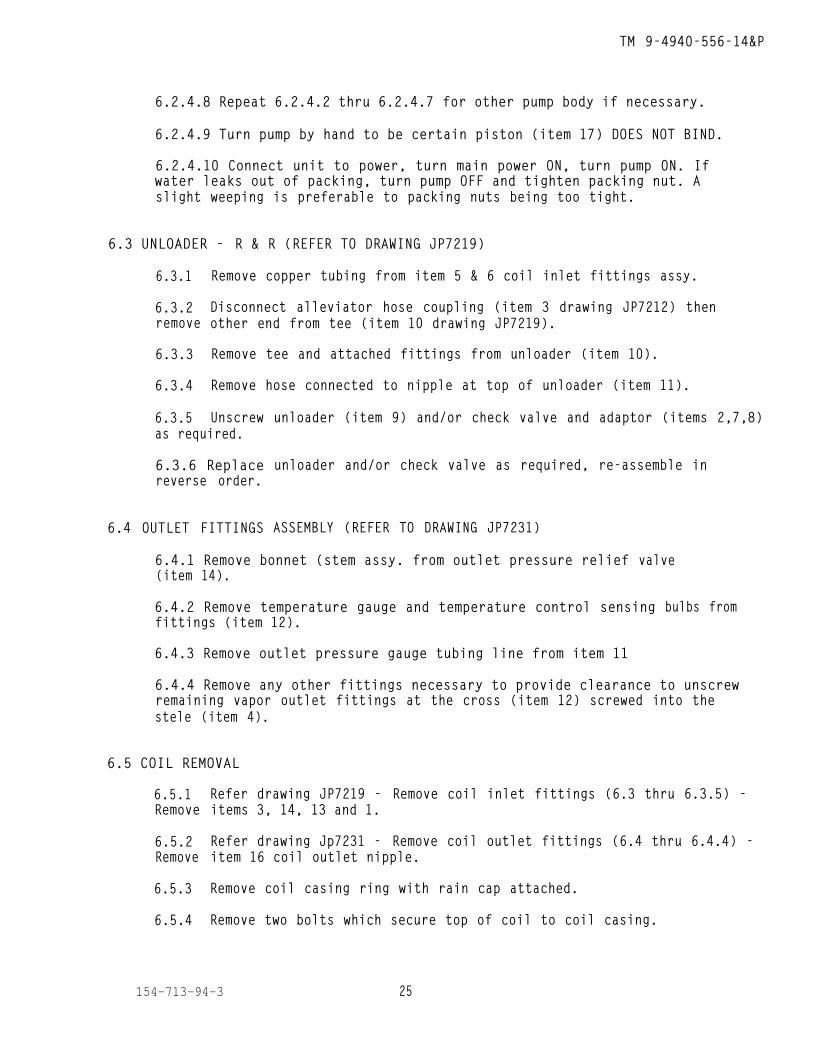
6.2.4.8 Repeat 6.2.4.2 thru 6.2.4.7 for other pump body if necessary.
6.2.4.9 Turn pump by hand to be certain piston (item 17) DOES NOT BIND.
6.2.4.10 Connect unit to power, turn main power ON, turn pump ON. Ifwater leaks out of packing, turn pump OFF and tighten packing nut. Aslight weeping is preferable to packing nuts being too tight.
6.3 UNLOADER - R & R (REFER TO DRAWING JP7219)
6.3.1
6.3.2remove
6.3.3
6.3.4
6.3.5
Remove copper tubing from item 5 & 6 coil inlet fittings assy.
Disconnect alleviator hose coupling (item 3 drawing JP7212) thenother end from tee (item 10 drawing JP7219).
Remove tee and attached fittings from unloader (item 10).
Remove hose connected to nipple at top of unloader (item 11).
Unscrewas required.
6.3.6 Replacereverse order.
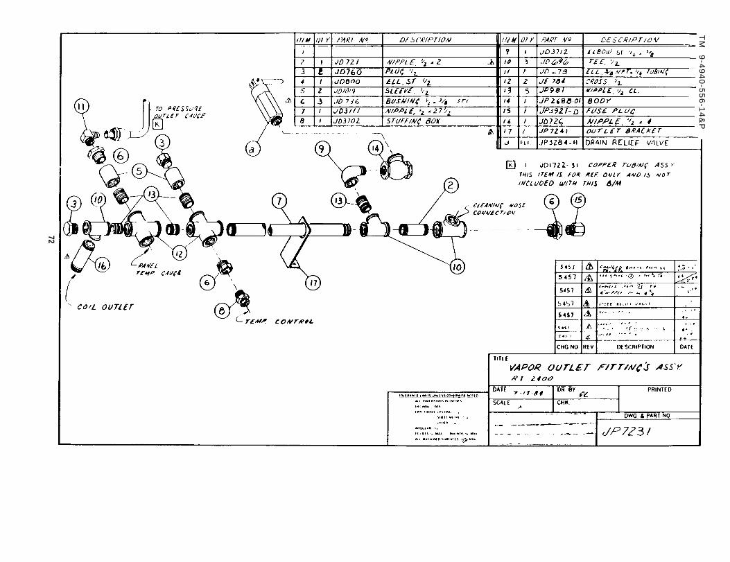
6.4 OUTLET FITTINGS
unloader (item 9) and/or check valve and adaptor (items 2,7,8)
unloader and/or check valve as required, re-assemble in
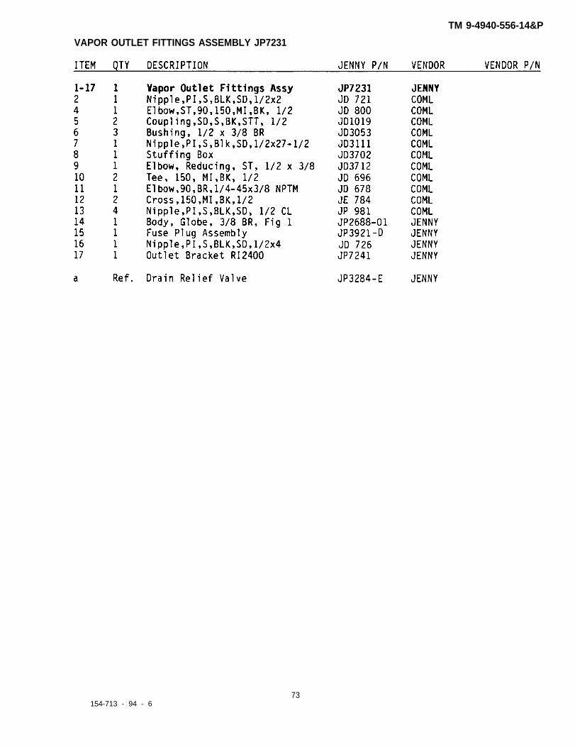
ASSEMBLY (REFER TO DRAWING JP7231)
6.4.1 Remove bonnet (stem assy. from outlet pressure relief(item 14).
6.4.2 Remove temperature gauge and temperature control sensing fittings (item 12).
6.4.3 Remove outlet pressure gauge tubing line from item 11
valve
bulbs from
6.4.4 Remove any other fittings necessary to provide clearance to unscrewremaining vapor outlet fittings at the cross (item 12) screwed into thestele (item 4).
6.5 COIL REMOVAL
6.5.1Remove
6.5.2Remove
6.5.3
6.5.4
Refer drawing JP7219 - Remove coil inlet fittings (6.3 thru 6.3.5) -items 3, 14, 13 and 1.
Refer drawing Jp7231 - Remove coil outlet fittings (6.4 thru 6.4.4) -item 16 coil outlet nipple.
Remove coil casing ring with rain cap attached.
Remove two bolts which secure top of coil to coil casing.
154-713-94-3 25
TM 9-4940-556-14&P
6.5.5 Connect chain or lifting strap to lifting/support bracket incenter of coil - coil weighs approximately 275 lbs. - be certain liftingstrap/chain is rated for at least 500 lbs.
6.5.6 Using an overhead crane, block and tackle, hoist or rigging devicelift the coil straight up and out of unit.
6.5.7 Either move coil away from unit and set down, or slide machineout from under coil.
6.5.8 Fire pot will stay in coil casing.
6.6 COIL INSULATION REMOVAL/REPLACEMENT
6.6.1 Remove coil (6.5 thru 6.5.7).
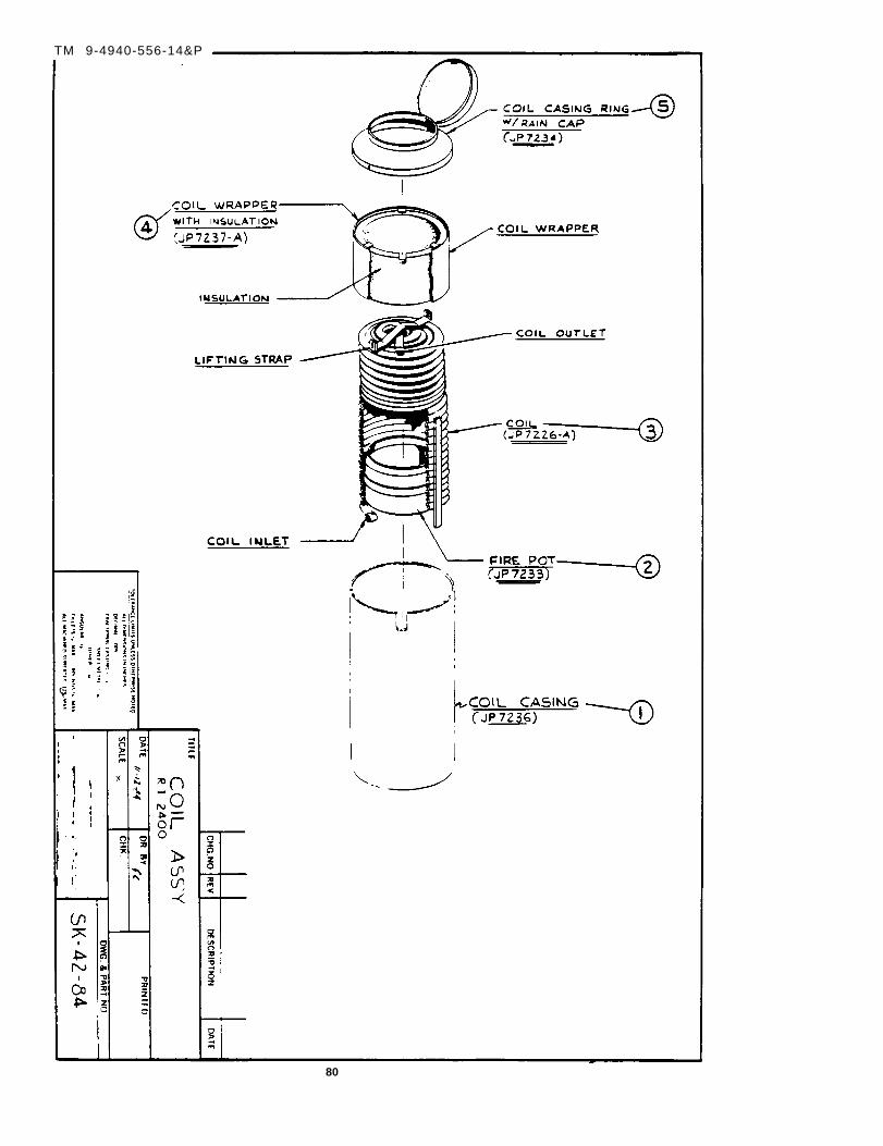
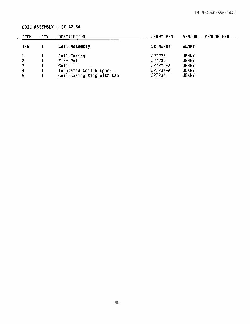
6.6.2 To remove coil installation, cut banding and remove (Ref. drawingSK-42-84). Carefully pull shroud away from coil and remove.
6.6.3 Reinstall coil insulation by reversing above procedure when applyingbanding to insulation, be certain not to crush filler insulation into spacebetween coils as combustion characteristics might be adversely affected.
6.7 FIRE-POT REMOVAL
6.7.1 Remove coil (6.5 thru 6.5.7).
6.7.2 Remove burner.
6.7.3 Reach into coil casing and lift pot out.
6.7.4 To replace fire pot, install burner, slide fire pot over burnerthroat, center fire pot carefully, re-install coil.
6.8 CLEANING GUN (REFER TO DRAWING JP7211).
6.9 FUEL SYSTEM - REFER TO DRAWING JP7110
This drawing shows the fuel tank and fittings assembly Including sightgauge, drain plug and outlet and return line fitting.
6.9.1 Fuel tank removal. Fuel tank is removed with solution tank as a unit.
6.9.2 Drain fuel tank using plug (item 1 drawing JP711O).
6.9.3 Disconnect copper fuel lines from tank (item 9 and 10 drawingJP711O).
6.9.4 Drain solution tank using plug on side. Disconnect solution linefrom tank.
26
TM 9-4940-556-14&P
6.9.5 Remove four (4) bolts from fuel/solution tank mounting flange -remove tank(s).
6.9.6 To re-install tank, reverse above procedure.
6.10 FUEL PUMP AND FITTINGS REMOVAL - REFER TO DRAWING JP7209-A
6.10.1 Drain fuel tank (see 6.9.2).
6.10.2 Disconnect three copper lines connected to fuel pump assembly(from item(s) 1 and 5).
6.10.3 Remove solenoid coil from fuel valve (item 9).
6.10.4 Remove two bolts which hold fuel pump to mounting bracket.
6.10.5 Remove fittings (items 1 thru 10) as necessary.
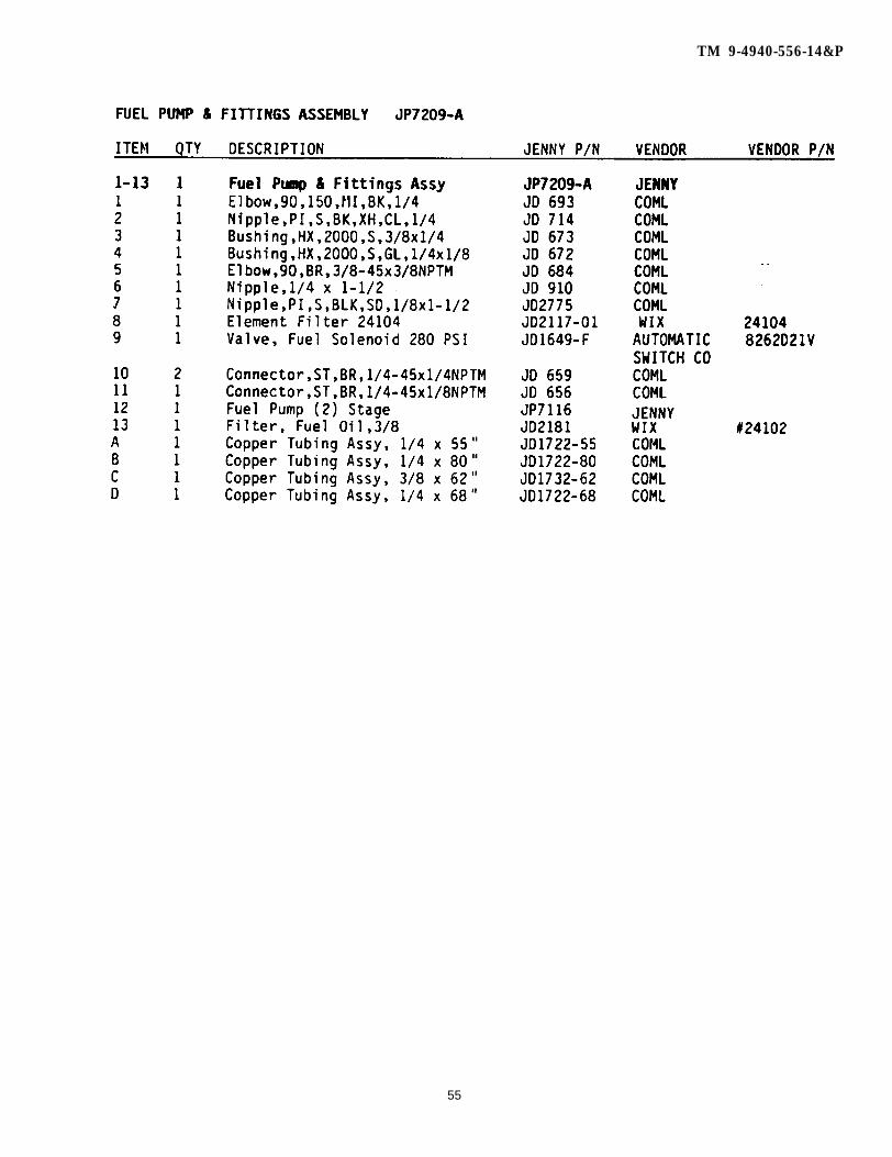
6.11 FUEL PUMP (PRESSURE) ADJUSTMENT - REFER TO DRAWING JP7209-D
6.11.1 The outlet temperature of the unit is a function of inlet watertemperature and fuel pressure. The fuel pump used on this unit has twosettings which function independently.
6.11.2 Steam fuel pressure adjustment.
6.11.2.1 The fuel pressure adjustment screw (item 1) is located on theside of the fuel pump. With the MODE switch in the STEAM position turnthe screw clockwise to increase the fuel pressure to the burner, counterclockwise to decrease fuel pressure to burner. With 65°F. inlet water,a fuel pressure setting of approximately 260 psi (as read on panel gauge)should heat outlet water to 350°F.
6.11.2.2 CAUTION - MAKE FUEL ADJUSTMENTS SLOWLY TO AVOID OVERHEATING.
6.11.3 Pressure rinse fuel pressure adjustemnt.
6.11.3.1 With pressure tip in gun, MODE switch in PRESSURE position setfuel pressure using screw on top of fuel pump (item 2). Turning the screwclockwise will increase fuel pressure to the burner, turning the screwcounter clockwise will decrease fuel pressure to the burner. A fuelpressure setting of 95 psi should, with incoming water of 65°F. producesan output temperature of 200°F.
6.11.3.2 CAUTION - MAKE ADJUSTMENTS SLOWLY TO PREVENT UNIT FROM OVERHEATING.
6.12 FUEL FILTER REMOVAL - (REF. DRAWING JP7209-A) . TURN MAIN POWER OFF.
6.12.1 Turn valve on top of fuel filter to OFF position (item 10).
6.12.2 Unscrew fuel filter, discard, install new fuel filter (item 10).
27
TM 9-4940-556-14&P
6.12.3 Turn fuel valve ON (item 10).
6.13 BURNER REMOVAL/REPAIR - (REF. TO DRAWING JP7222) - TURN MAIN POWER OFF.
6.13.1 Turn fuel OFF at fuel filter.
6.13.2 Disconnect fuel line from burner at anti-syphon fitting assembly.
6.13.t w o
6.13.wing
3 Disconnect high voltage from electrodes (item 9) and disconnect(2) wires connected to FLAME switch.
4 Remove burner protector guard and burner assembly by removingnuts holding both on to the bottom of the chassis. Be certain not
to damage the grounding wire connected to the burner.
6.13.5 Burner jet assembly.
6.13.5.1 Using a box wrench on burner jet and pipe wrench on burnernipple, remove burner jet. (Refer to drawing JP7222) dis-assemble jetwhirler and strainer.
6.13.5.2 Soak jet whirler and strainer in dry cleaning solvent,NSN 6850-00-664-5682, or 1,1,1 -Trichloroethane NSN 6810-00-292-9625,while burner jet/strainer, and (fuel.) whirler are soaking, scrape carbonfrom air whirler.
6.13.5.3 Re-assemble jet/whirler/strainer and install into burner nipple.
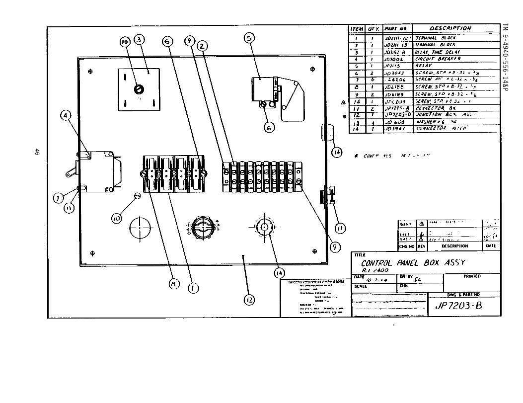
6.14 ELECTRICAL SYSTEM - REFER TO DRAWINGS JP7200, JP7201, JP7201-A, JP7203-B.
WARNING - MOST OF THE FOLLOWING ADJUSTMENTS MUST BE MADEWHILE POWER IN ON AND UNIT IS OPERATING. UNIT WILL BEOPERATED WITHOUT PROTECTIVE COVERS IN PLACE. DO NOT TOUCHELECTRICAL WIRING AND DO NOT BECOME ENTANGLED IN MOVINGAPPARATUS.
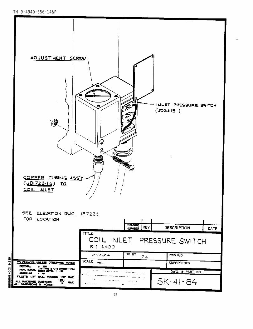
6.14.1 Pressure switch adjustment. Remove cover over pressure switchadjusting screw (ref. drawing SK-41-84). With STEAM position and the gunheld open, water supply connected to unit, turn main power switch ON.
6.14.1.1 Turn adjusting screw counter clockwise till it stops.
6.14.1.2 Turn adjusting screw clockwise three (3) turns.
6.14.1.3 Turn burner switch ON - turn adjusting screw on PRESSURE switch(item 1) counter clockwise till burner ignites, the turn counter clockwisean additional 1/16 turn.
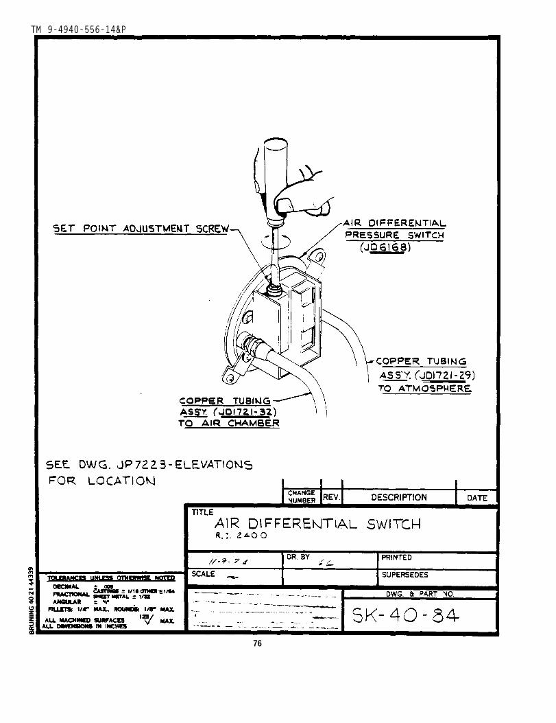
6.14.2 Air differential switch adjustment. Remove cover from and locateadjustment screw on top of switch (ref. drawing SK-40-84).
6.14.2.1 Rotate screw counter clockwise till it stops.
28
TM 9-4940-556-14&P
6.14.2.2 a. Install pressure wash tip in gun.b. Turn main power switch ON.c. Turn pump switch ON.d. Set MODE switch to PRESSURE.e. Close air baffle on blower.f. Hold gun OPEN.
6.14.2.3 Turn burner switch ON. If burner does not ignite, turn burnerswitch OFF. Turn air switch adjusting screw clockwise 1/4 turn. Turnburner switch ON.
6.14.2.4 Repeat 6.14.2.3 until burner ignites, then turn adjusting screwclockwise an additional 1/4 turn.
6.14.3 Thermal control - (ref. drawing JP7223). Thermal control isfactory set for a maximum of 360°F. DO NOT adjust this high stop.Outlet temperature can be reduced by turning thermal control dial to alower setting, however, temperature will swing ±lO°F. from the selected(lower) temperature and un-satisfactory cleaning may result.
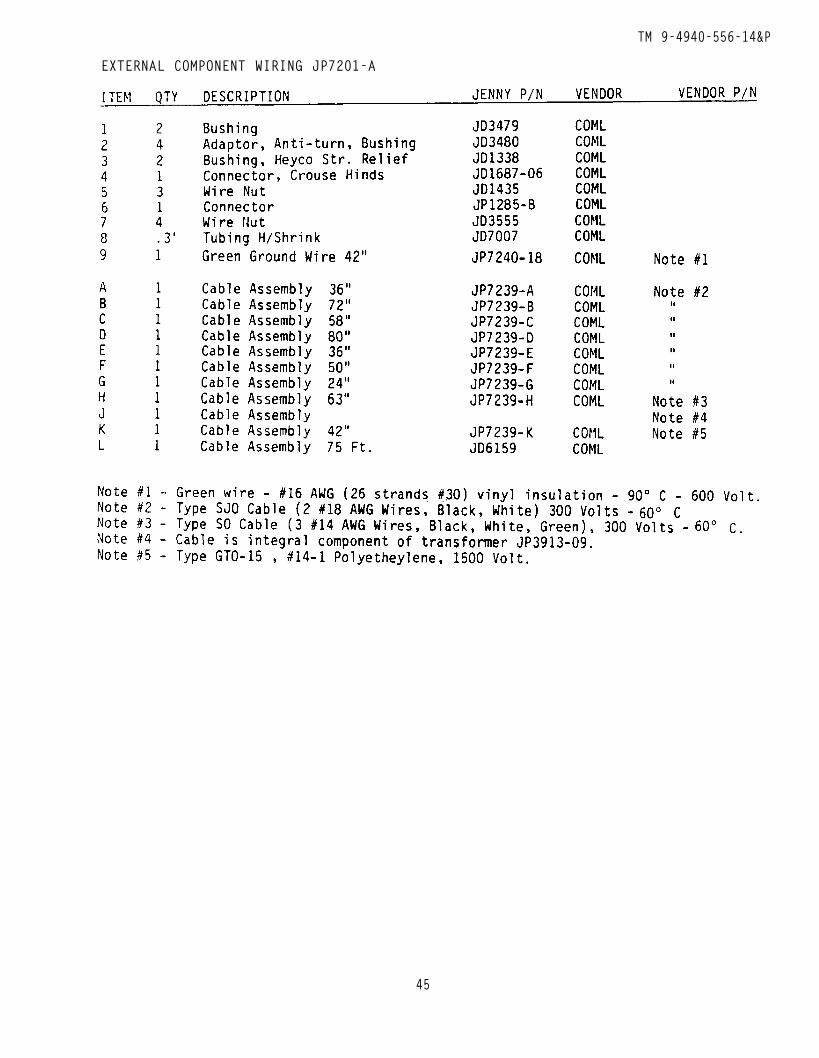
6.14.4 Wiring (ref. to drawing JP7200, JP7201, JP7201-A and JP7203-B).Wire #16 AWG-(26 strands/#30) 600 volt, 60°C vinyl insulation-(Jenny JD3871 Ref. P/N)
6.14.4.1 To repair wiring, be certain to work only when the unit hasbeen disconnected from all electrical power.
6.14.4.2 Always replace wires with those of equal or greater anddielectric strength.
6.14.4.3 Never splice wires, always replace.
6.14.4.4 When replacing wires, be certain they are protected againstmechanical damage and abrasion.
6.14.5 For detailed description of the operation and inter relationof electrical components (ref. to section
6.14.6 Transformer - Test - Replacement
3.8 and 5.4.1).
WARNING
These proceduresand performed byrepairs.
- HIGH VOLTAGE
require the electrical power to be disconnected -personnel trained to make high voltage electrical
6.14.6.1 Disconnect Electrical Power. Also turn circuit breakerS-1 to off position Ref. Dwg. SK-8-85).
6. 14.6.2 Open the cover of the Switch Panel. Locate cable “J”and the black and white wire of the cable and disconnect fromTerminal No. 1 and No. 2.
6.14.6.3 Disconnect the high voltage cable “C” at the bottom ofthe Burner Assembly (Ref. Dwg. JP7222).
29
TM 9-4940-556-14&P
6.14.6.4 SECONDARY TESTOne lead from an OHM-Meter to the high voltage terminal and the 2ndlead from the OHM-Meter to transformer ground. The meter shouldread somewhat less than 13,500 OHMS. An infinite reading wouldindicate an open circuit of high voltage cable “C” or transformer.Replace high voltage cable and repeat the test. An infinitereading - replace transformer.
6.14.6.5 Transformer replacement.
6.14.6.5.1 Remove high voltage cable assembly from transformer.
6.14.6.5.2 Remove ground wire from transformer.
6.14.6.5.3 Disconnect transformer lead wire from No. 1 and No. 2terminals in J-Box. Thread wire thru rear of J-Box Assembly.
6.14.6.5.4 Loosen and remove nuts holding transformer base plateto coil casing.
6.14.6.5.5 Remove transformer.
6.14.6.5.6 To replace transformer, reverse steps 6.14.6.5.1 thru6.14.6.5.5.
6.15 MECHANICAL DRIVE SYSTEM
6.15.1 Fan/Blower Wheel removal.
6.15.1.1 Empty fuel tank.
6.15.1.2 Remove line to fuel pressure gauge.
6.15.1.3 Remove fuel line connecting to fuel filter.
6.15.1.4 Loosen motor bolts, loosen pump mounting bolts, slide pumpthen motor to right. Remove pump drive belt.
6.15.1.5 Remove Jack Shaft drive belt from motor pulley.
6.15.1.6 Remove fuel pump mounting bolts, remove fuel pump and couplingand (leaving wires connected) move pump out of the way.
30
TM 9-4940-556-14&P
6.15.1.7 Loosen set screw on blower hub, slide blower back on jackshafttill it hits jackshaft drive pulley.
6.15.1.8 Remove the four bolts which hold jackshaft bracket to mountingbase.
6.15.1.9 Slide pillow block mounting base toward front of machine tillblower can be removed from the end of jackshaft.
6.15.1.10 To reinstall blower, reverse above procedure (6.15.1.1 -6.15.1.10). Always align pulleys to prevent premature belt wear. Loosen setscrews on both motor pulley and jackshaft pulley. Check and adjustalignment between pump and motor pulley. Tighten motor pulley. Checkand adjust alignment between motor and jackshaft pulleys. Tighten jack-shaft pulley. If necessary retension belts as in 4.5.1.
6.15.2 Jack Shaft Drive belt Replacement.
6.15.2.1 Follow 6.15.1.1 thru 6.15.1.7 and 6.15.1.9.
6.15.2.2 Slide pillow block mounting base toward front of machine tilldrive belt can be slipped over blower wheel and removed.
6.15.2.3 Install new belt over blower wheel and reverse above procedureto re-assemble unit (6.15.2.1 - 6.15.2.2). Always align pulleys to preventpremature belt wear. Loosen set screws on both motor pulley and jackshaftpulley. Check and adjust alignment between pump and motor pulley. Tightenmotor pulley. Check and adjust alignment between motor and jackshaft pulleysTighten jackshaft pulley. If necessary retension belts as in 4.5.1.
6.15.3 Pillow Block Bearing Replacement.
6.15.3.1 Follow 6.15.1.1 thru 6.15.1.7.
6.15.3.2 Loosen set screw (s) holding pillow block bearing (s) to jackshaft.
6.15.3.3 Slide pillow block (s) toward fuel pump mounting bracket till itcomes off of the shaft.
6.15.3.4 To reinstall, reverse 6.15.3.1 thru 6.15.3.3. Always align pulleysto prevent premature belt wear. Loosen set screws on both motor pulley andjackshaft pulley. Check and adjust alignment between pump and motor pulley.Tighten motor pulley. Check and adjust alignment between motor and jack-shaft pulleys. Tighten jackshaft pulley. If necessary retension belts asin 4.5.1.
31

THIS PAGE LEFT INTENTI0NALLY BLANK
32
TM 9-4940-556-14&P
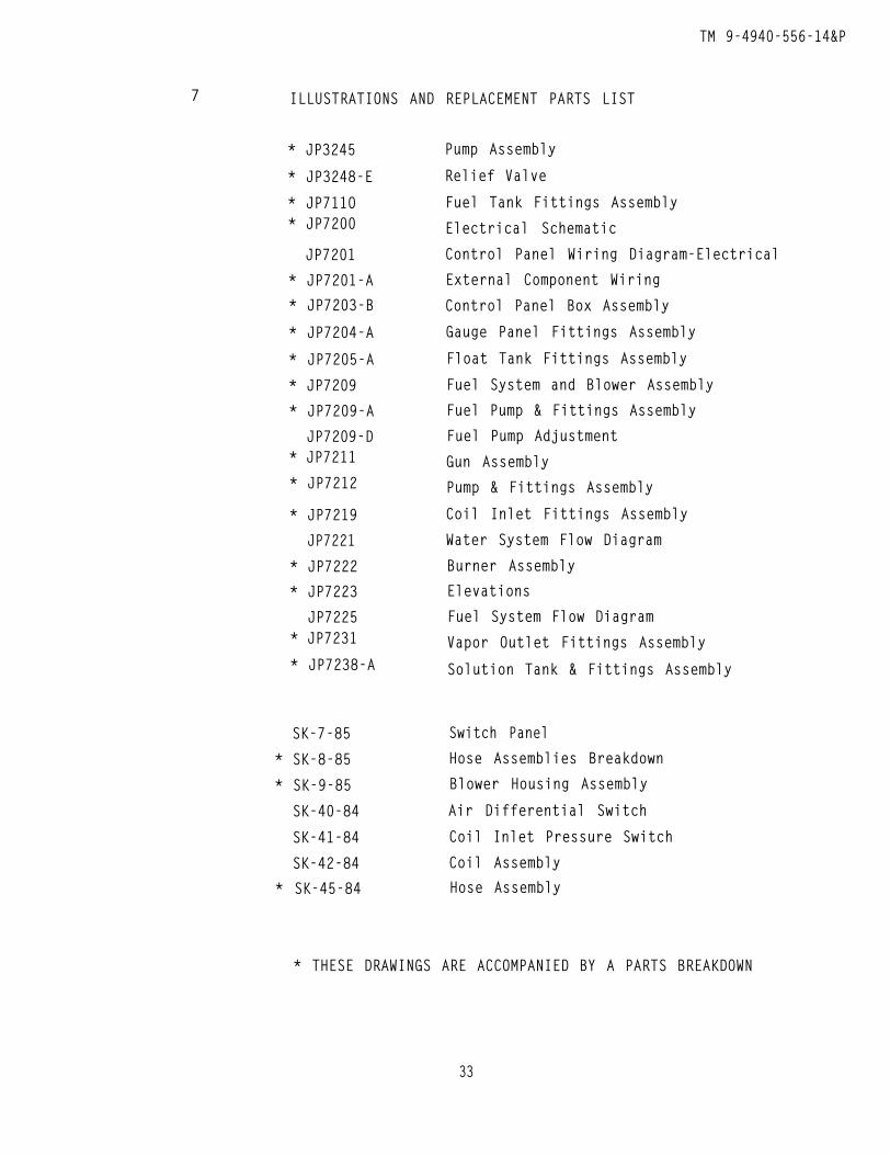
7 ILLUSTRATIONS AND REPLACEMENT PARTS LIST
* JP3245
* JP3248-E
* JP711O* JP7200
JP7201
* JP7201-A
* JP7203-B
* JP7204-A
* JP7205-A
* JP7209
* JP7209-A
JP7209-D* JP7211
* JP7212
* JP7219
JP7221
* JP7222
* JP7223
JP7225* JP7231
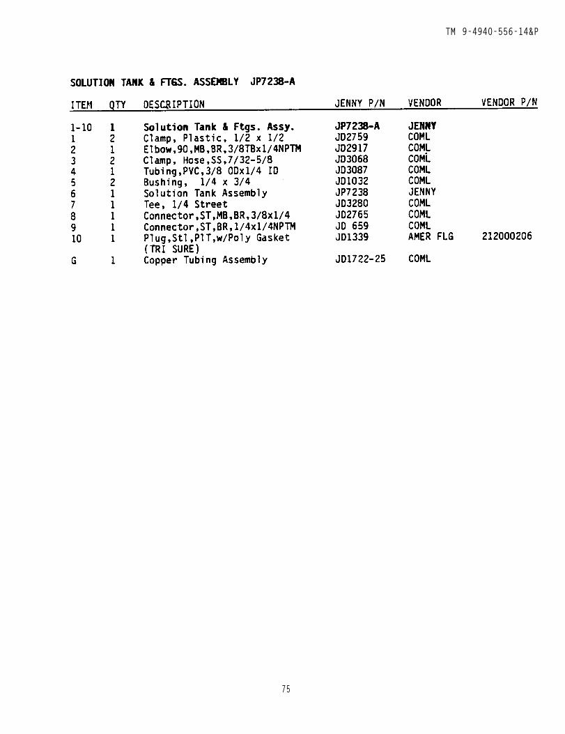
* JP7238-A
Pump Assembly
Relief Valve
Fuel Tank Fittings Assembly
Electrical Schematic
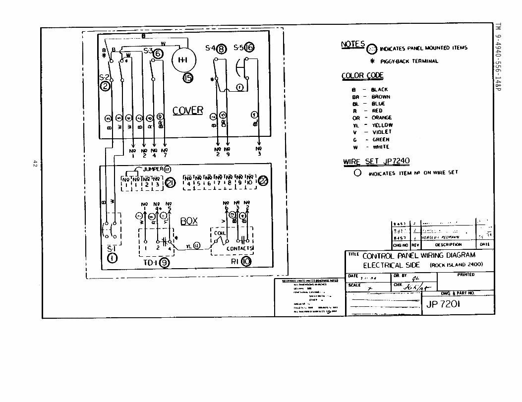
Control Panel Wiring Diagram-Electrical
External Component Wiring
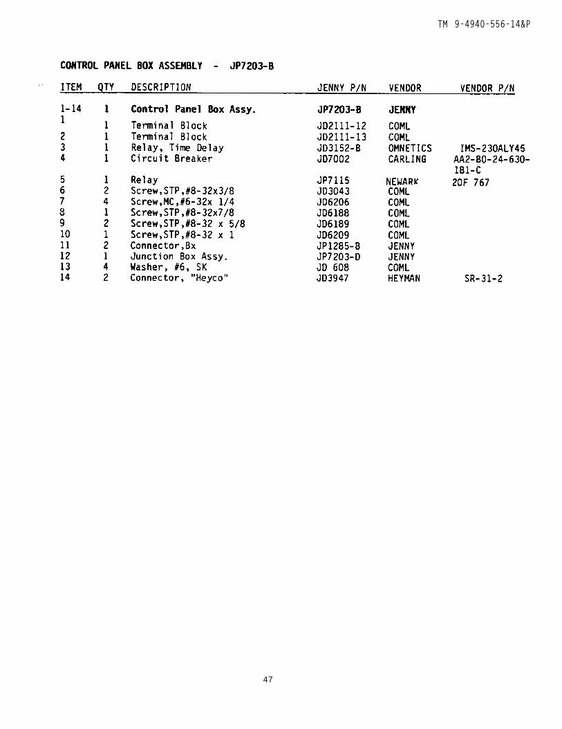
Control Panel Box Assembly
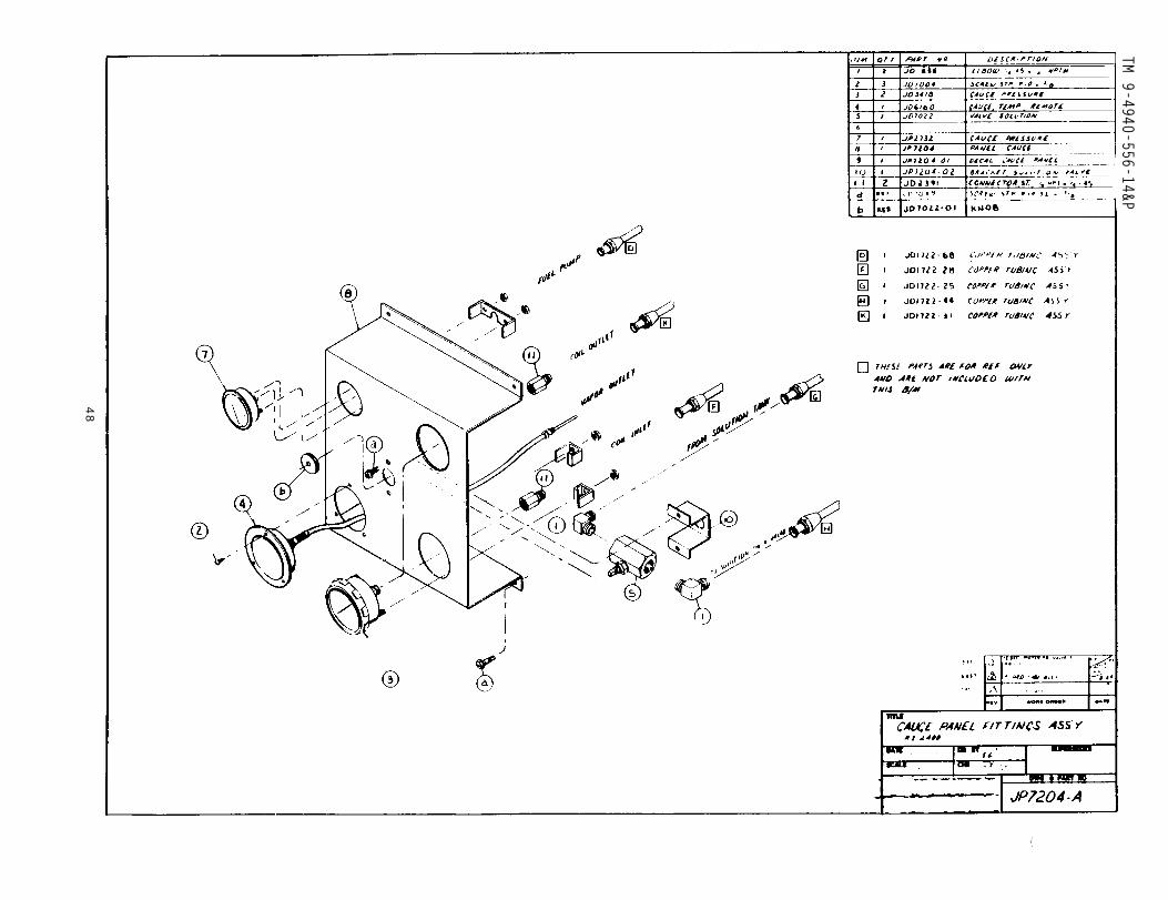
Gauge Panel Fittings Assembly
Float Tank Fittings Assembly
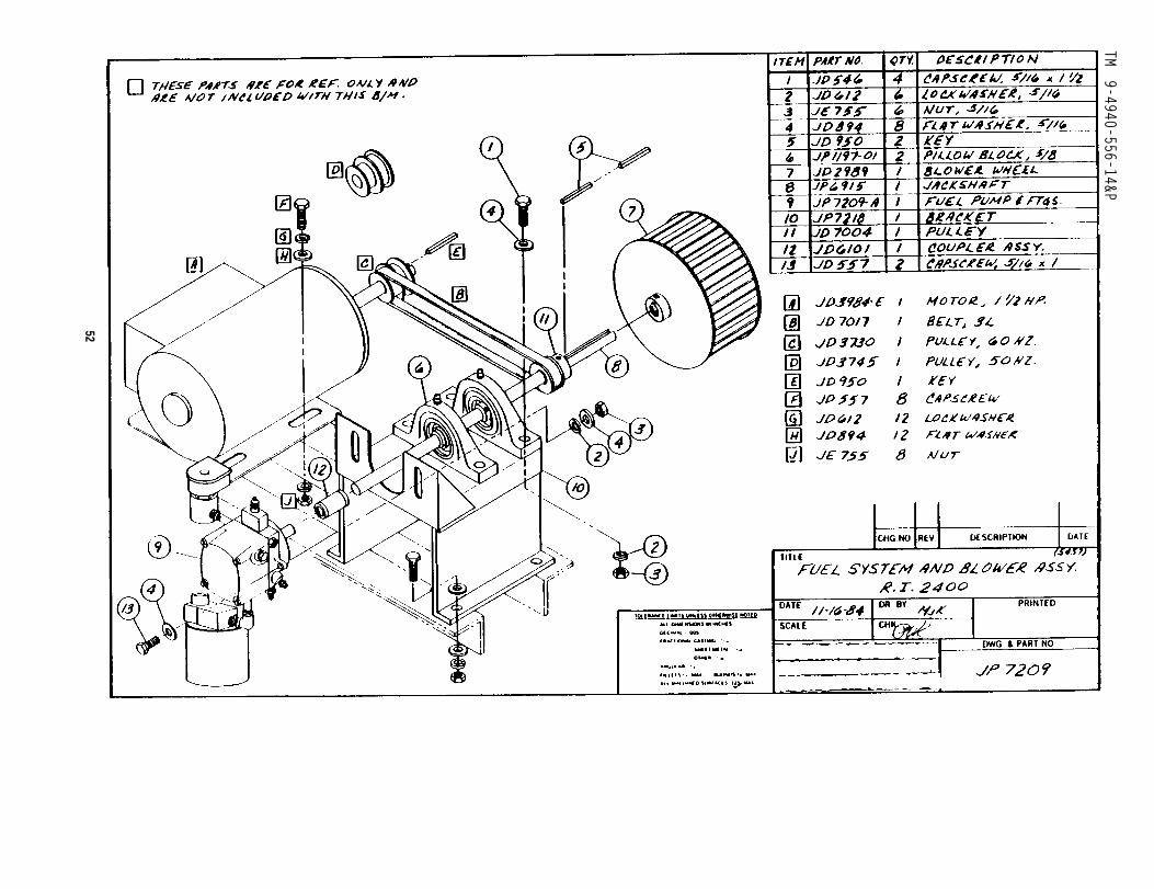
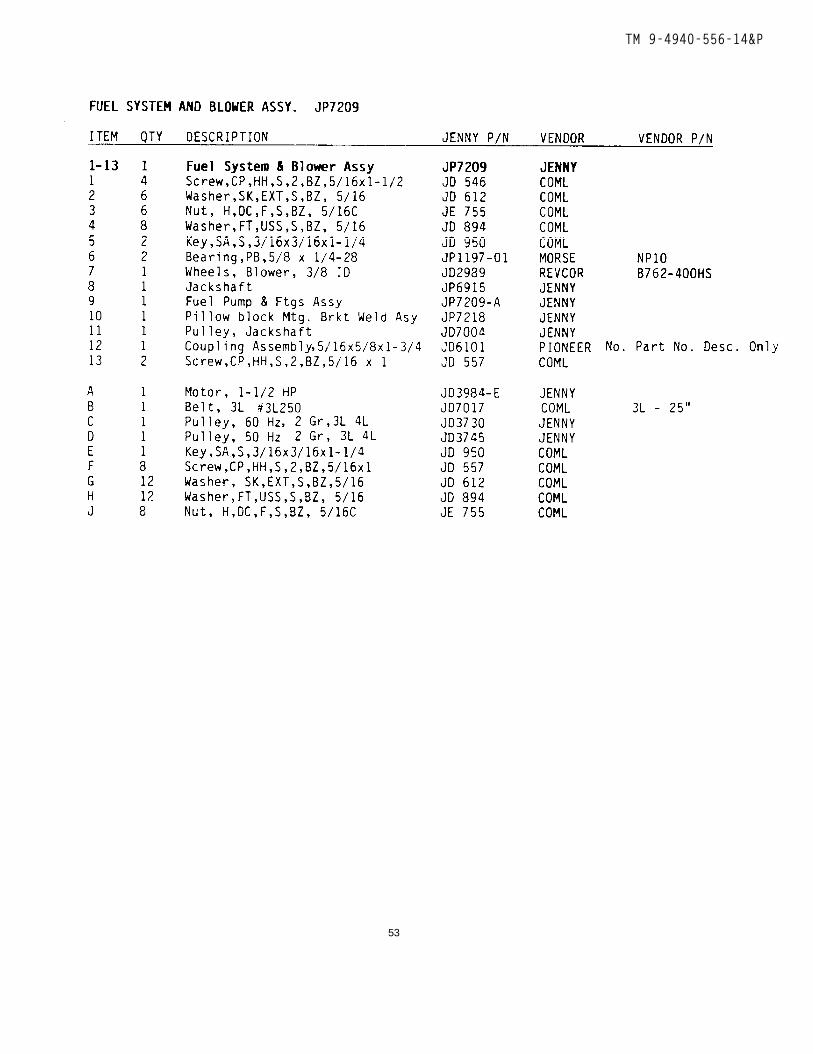
Fuel System and Blower Assembly
Fuel Pump & Fittings Assembly
Fuel Pump Adjustment
Gun Assembly
Pump & Fittings Assembly
Coil Inlet Fittings Assembly
Water System Flow Diagram
Burner Assembly
Elevations
Fuel System Flow Diagram
Vapor Outlet Fittings Assembly
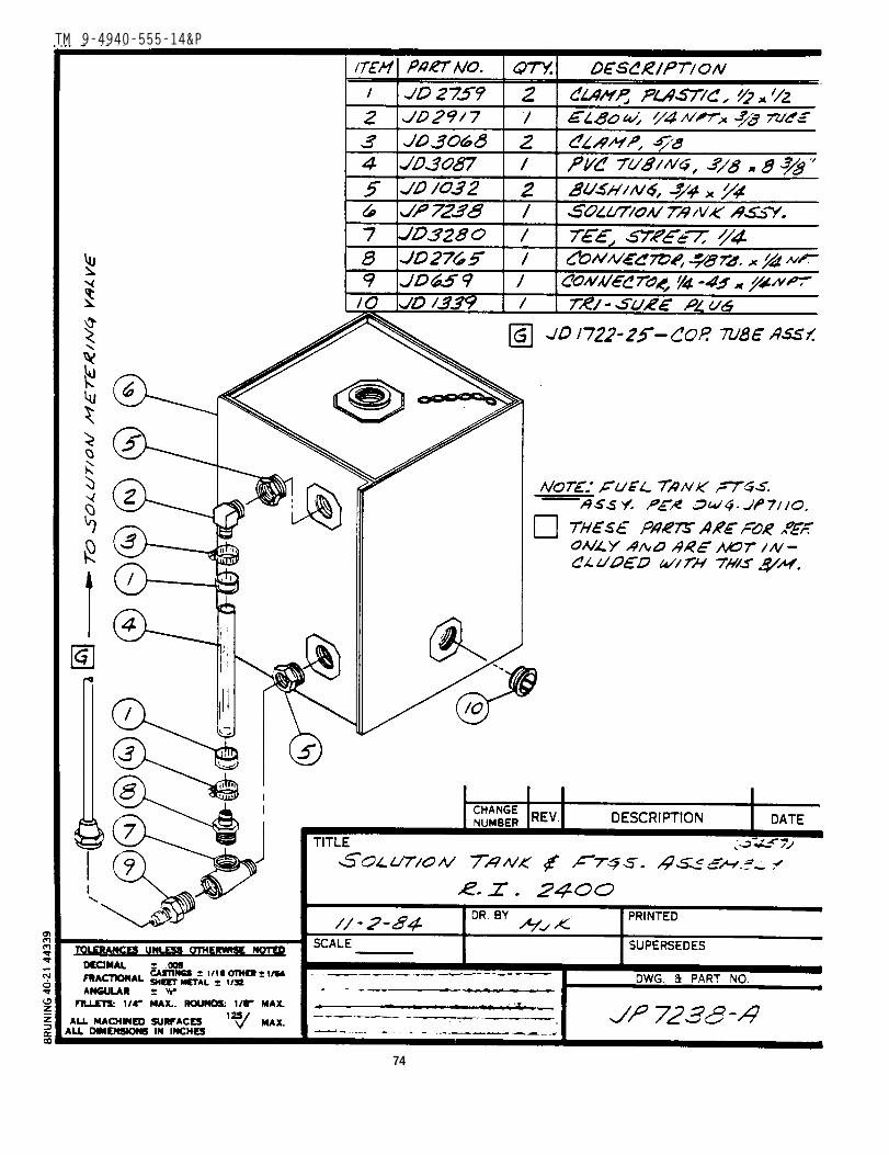
Solution Tank & Fittings Assembly
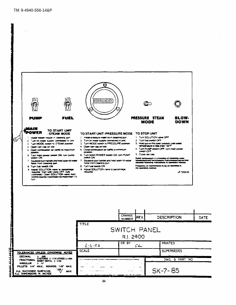
SK-7-85 Switch Panel
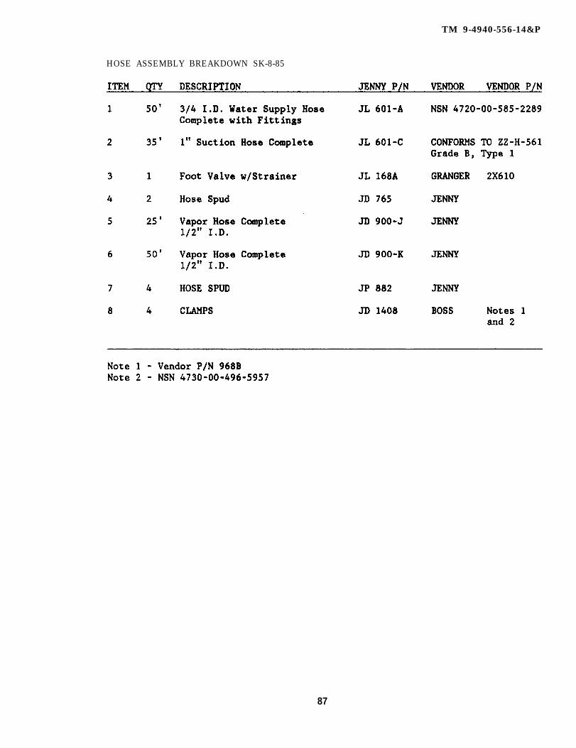
* SK-8-85 Hose Assemblies Breakdown
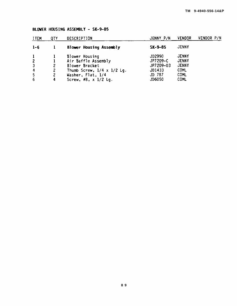
* SK-9-85 Blower Housing Assembly
SK-40-84 Air Differential Switch
SK-41-84 Coil Inlet Pressure Switch
SK-42-84 Coil Assembly
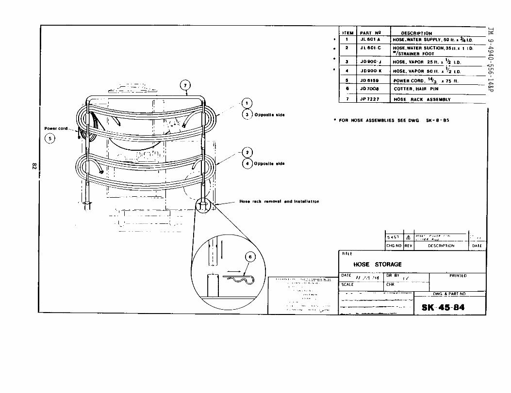
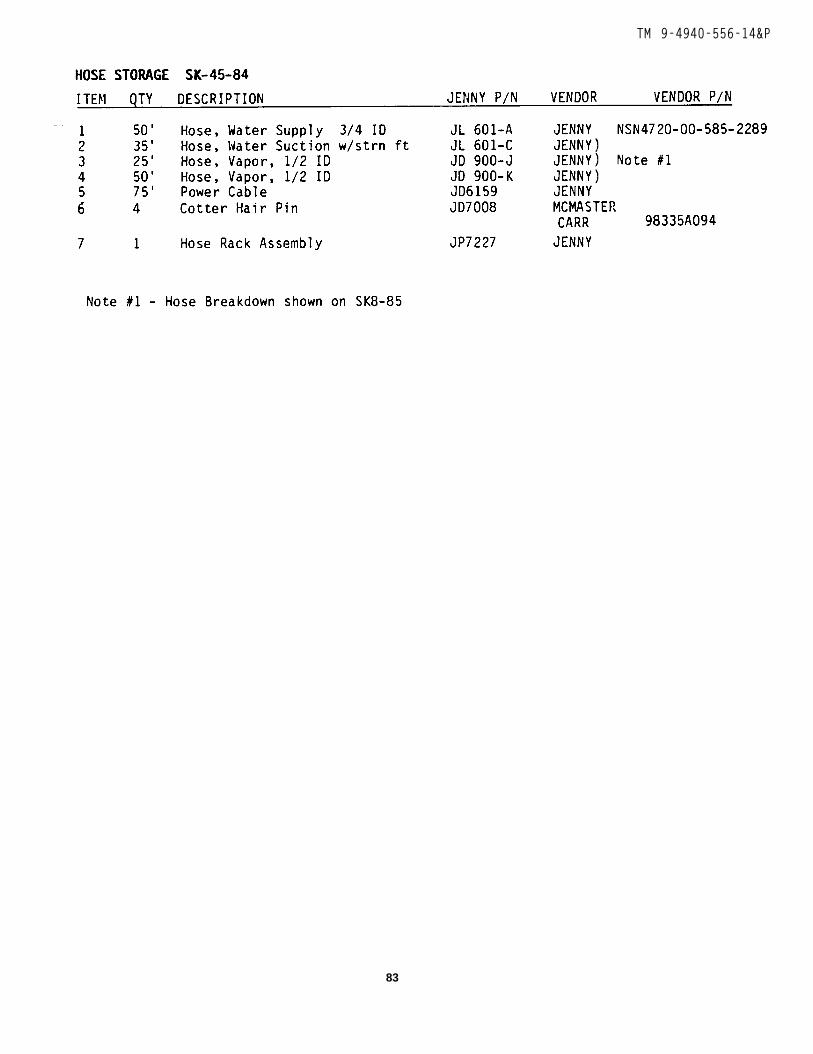
* SK-45-84 Hose Assembly
* THESE DRAWINGS ARE ACCOMPANIED BY A PARTS BREAKDOWN
33
TM 9-4940-556-14&P
34
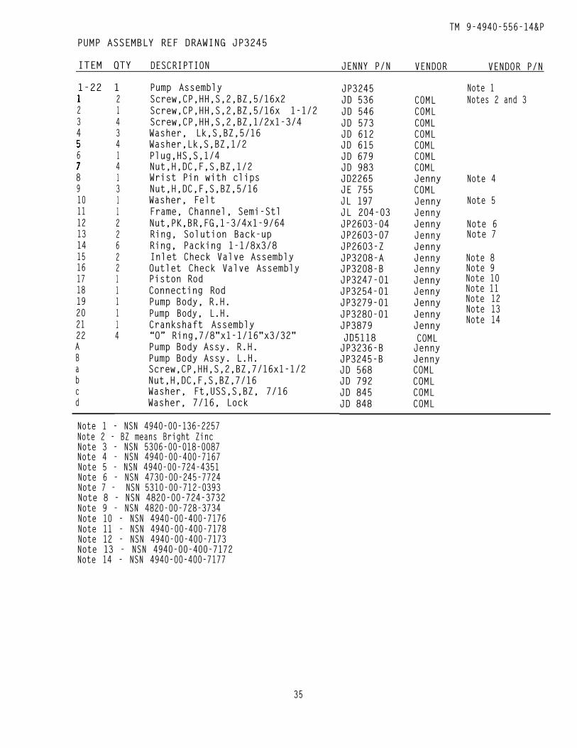
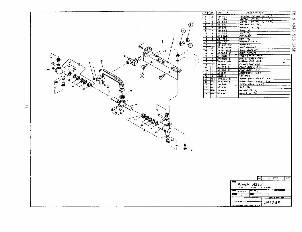
TM 9-4940-556-14&PPUMP ASSEMBLY REF DRAWING JP3245
ITEM QTY DESCRIPTION JENNY P/N VENDOR VENDOR P/N
1-22 1
234
6
8910111213141516171819202122ABabcd
2143414131122622111114
Pump AssemblyScrew,CP,HH,S,2,BZ,5/16x2Screw,CP,HH,S,2,BZ,5/16x 1-1/2Screw,CP,HH,S,2,BZ,1/2x1-3/4Washer, Lk,S,BZ,5/16Washer,Lk,S,BZ,1/2Plug,HS,S,1/4Nut,H,DC,F,S,BZ,1/2Wrist Pin with clipsNut,H,DC,F,S,BZ,5/16Washer, FeltFrame, Channel, Semi-StlNut,PK,BR,FG,1-3/4x1-9/64Ring, Solution Back-upRing, Packing 1-1/8x3/8Inlet Check Valve AssemblyOutlet Check Valve AssemblyPiston RodConnecting RodPump Body, R.H.Pump Body, L.H.Crankshaft Assembly“O” Ring,7/8"x1-1/16"x3/32"Pump Body Assy. R.H.Pump Body Assy. L.H.Screw,CP,HH,S,2,BZ,7/16x1-1/2Nut,H,DC,F,S,BZ,7/16Washer, Ft,USS,S,BZ, 7/16Washer, 7/16, Lock
Note 1 - NSN 4940-00-136-2257Note 2 - BZ means Bright ZincNote 3 - NSN 5306-00-018-0087Note 4 - NSN 4940-00-400-7167Note 5 - NSN 4940-00-724-4351Note 6 - NSN 4730-OO-245-7724Note 7 - NSN 5310-00-712-0393Note 8 - NSN 4820-00-724-3732Note 9 - NSN 4820-00-728-3734Note 10 - NSN 4940-00-400-7176Note 11 - NSN 4940-00-400-7178Note 12 - NSN 4940-00-400-7173Note 13 - NSN 4940-00-400-7172Note 14 - NSN 4940-00-400-7177
JP3245JD 536JD 546JD 573JD 612JD 615JD 679JD 983JD2265JE 755JL 197JL 204-03JP2603-04JP2603-07JP2603-ZJP3208-AJP3208-BJP3247-01JP3254-01JP3279-01JP3280-01JP3879JD5118JP3236-BJP3245-BJD 568JD 792JD 845JD 848
COMLCOMLCOMLCOMLCOMLCOMLCOMLJennyCOMLJennyJennyJennyJennyJennyJennyJennyJennyJennyJennyJennyJennyCOMLJennyJennyCOMLCOMLCOMLCOML
Note 1Notes 2 and 3
Note 4
Note 5
Note 6Note 7
Note 8Note 9Note 10Note 11Note 12Note 13Note 14
35
TM 9-4940-556-14&P
36
TM 9-4940-556-14&P
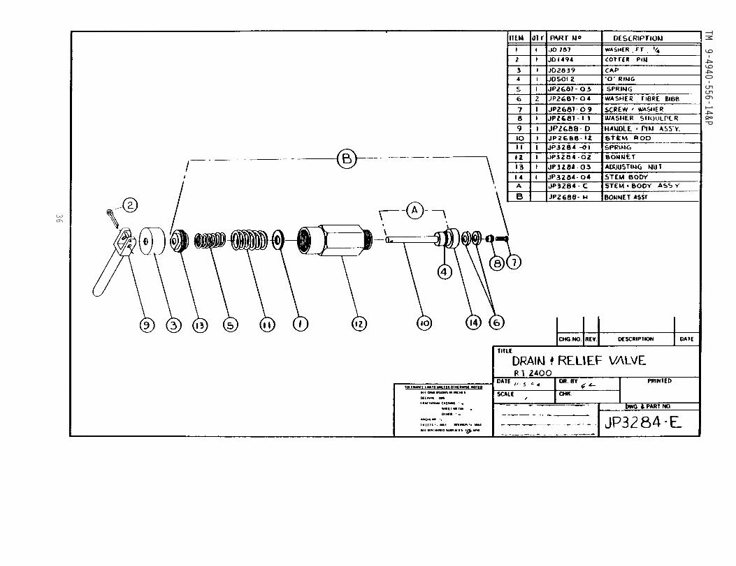
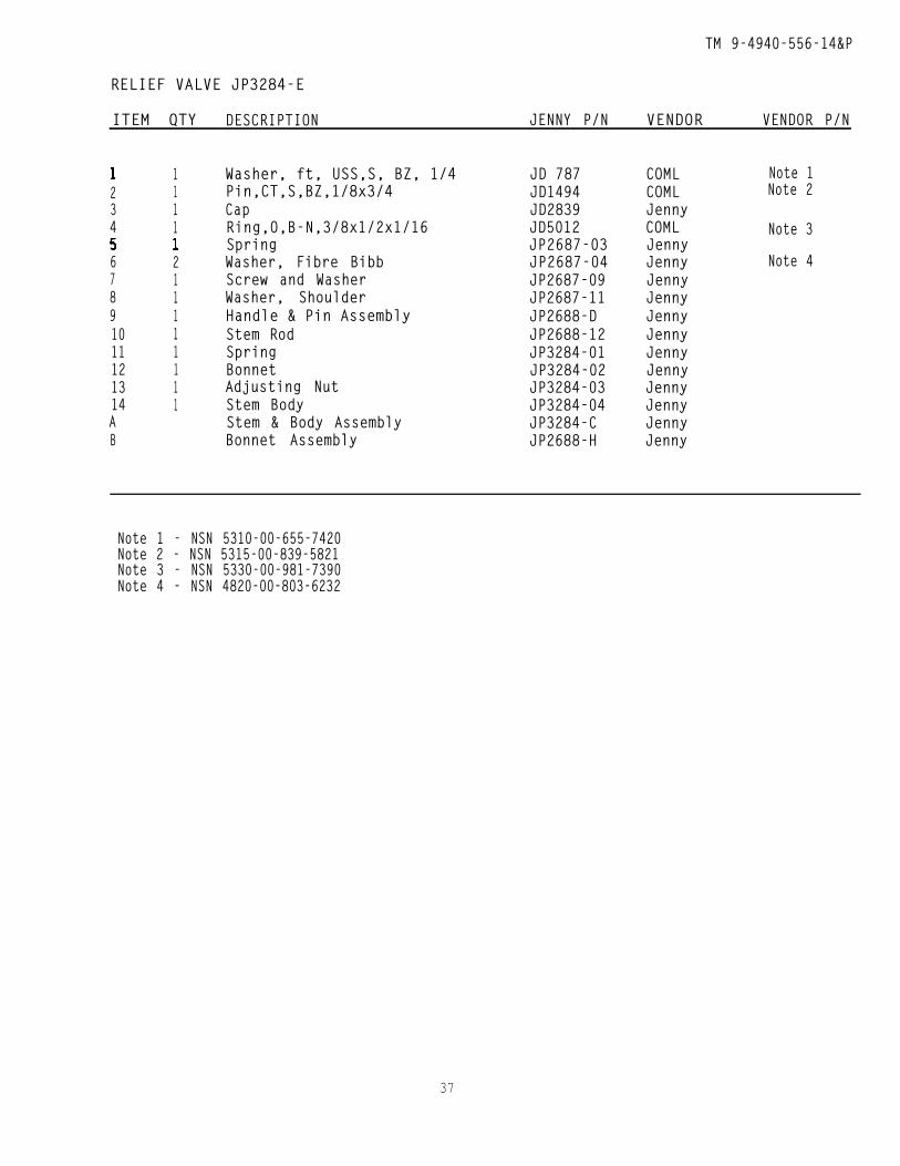
RELIEF VALVE JP3284-E
ITEM QTY DESCRIPTION JENNY P/N VENDOR VENDOR P/N
234
67891011121314AB
1111
211111111
Washer, ft, USS,S, BZ, 1/4Pin,CT,S,BZ,1/8x3/4CapRing,O,B-N,3/8x1/2x1/16SpringWasher, Fibre BibbScrew and WasherWasher, ShoulderHandle & Pin AssemblyStem RodSpringBonnetAdjusting NutStem BodyStem & Body AssemblyBonnet Assembly
JD 787JD1494JD2839JD5012JP2687-03JP2687-04JP2687-09JP2687-11JP2688-DJP2688-12JP3284-01JP3284-02JP3284-03JP3284-04JP3284-CJP2688-H
COML Note 1COML Note 2JennyCOML Note 3JennyJenny Note 4JennyJennyJennyJennyJennyJennyJennyJennyJennyJenny
Note 1 - NSN 5310-00-655-7420Note 2 - NSN 5315-00-839-5821Note 3 - NSN 5330-00-981-7390Note 4 - NSN 4820-00-803-6232
37
TM 9-4940-556-14&P
38
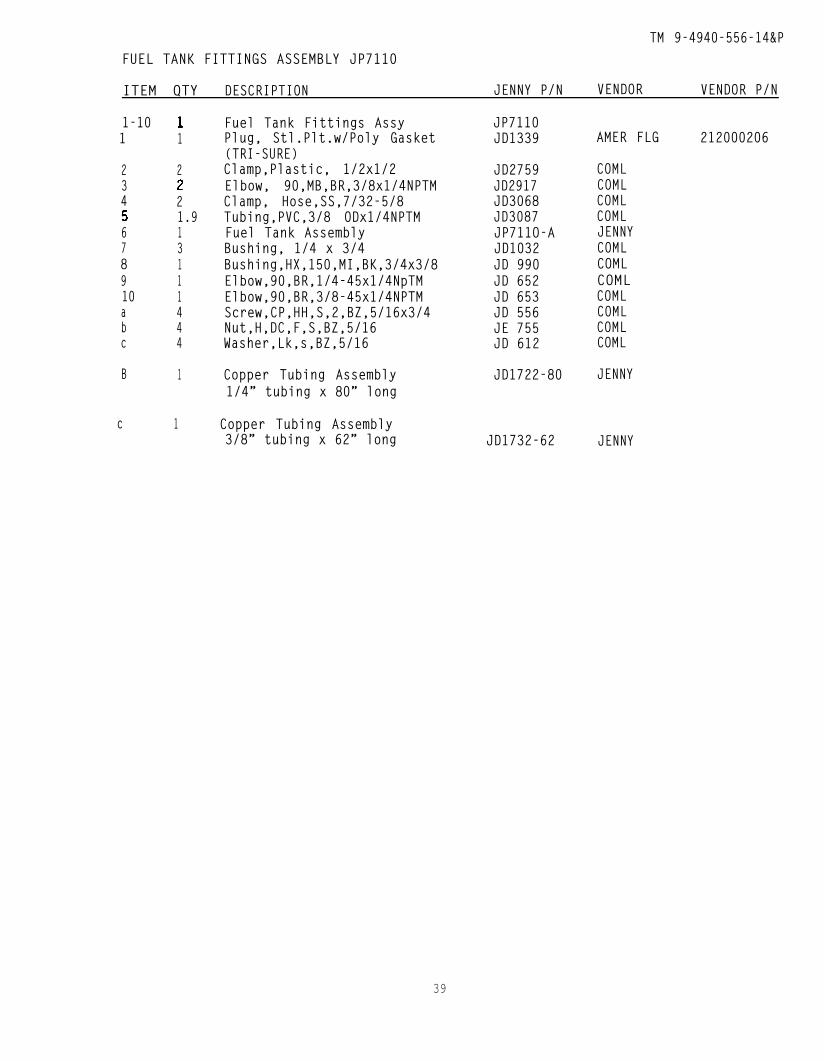
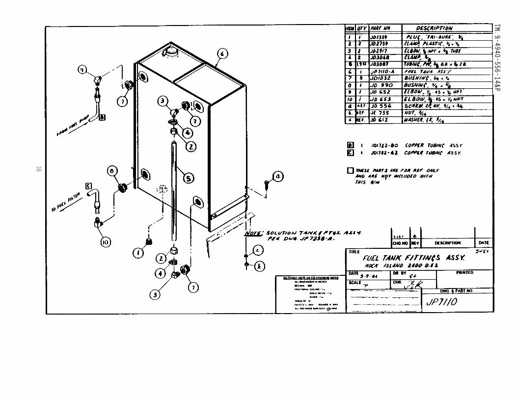
TM 9-4940-556-14&PFUEL TANK FITTINGS ASSEMBLY JP7110
ITEM QTY DESCRIPTION JENNY P/N VENDOR VENDOR P/N
1-101
234
678910abc
B
c
1
2
21.913111444
1
1
Fuel Tank Fittings AssyPlug, Stl.Plt.w/Poly Gasket(TRI-SURE)Clamp,Plastic, 1/2x1/2Elbow, 90,MB,BR,3/8x1/4NPTMClamp, Hose,SS,7/32-5/8Tubing,PVC,3/8 ODx1/4NPTMFuel Tank AssemblyBushing, 1/4 x 3/4Bushing,HX,150,MI,BK,3/4x3/8Elbow,90,BR,1/4-45x1/4NpTMElbow,90,BR,3/8-45x1/4NPTMScrew,CP,HH,S,2,BZ,5/16x3/4Nut,H,DC,F,S,BZ,5/16Washer,Lk,s,BZ,5/16
Copper Tubing Assembly1/4” tubing x 80” long
Copper Tubing Assembly3/8” tubing x 62” long
JP7110JD1339
JD2759JD2917JD3068JD3087JP711O-AJD1032JD 990JD 652JD 653JD 556JE 755JD 612
JD1722-80
JD1732-62
AMER FLG 212000206
COMLCOMLCOMLCOMLJENNYCOMLCOMLCOMLCOMLCOMLCOMLCOML
JENNY
JENNY
39
TM 9-4940-556-14&P
40

TM 9-4940-556-14&P
41154-713 - 94 - 4
TM 9-4940-556-14&P
42

TM 9-4940-556-14&P
THIS PAGE LEFT INTENTIONALLY BLANK
43
TM 9-4940-556-14&P
44
TM 9-4940-556-14&P
EXTERNAL COMPONENT WIRING JP7201-A
45
TM 9-4940-556-14&P
46
TM 9-4940-556-14&P
47
TM 9-4940-556-14&P
48

TM 9-4940-556-14&P
49
TM 9-4940-55614&P
50
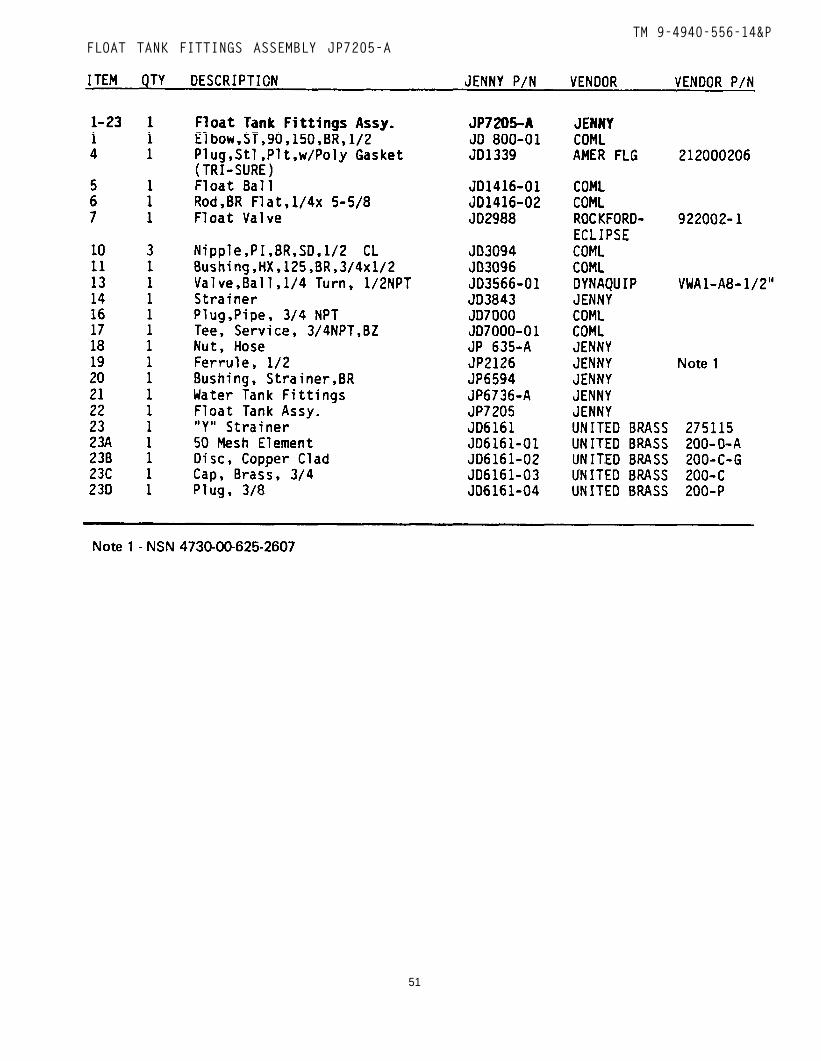
TM 9-4940-556-14&PFLOAT TANK FITTINGS ASSEMBLY JP7205-A
51
TM 9-4940-556-14&P
52
TM 9-4940-556-14&P
53
TM 9-4940-556-14&P
54
TM 9-4940-556-14&P
55
TM 9-4940-556-14&P
56

154-713 - 94 - 5
TM 9-4940-556-14&P
THIS PAGE LEFT INTENTIONALLY BLANK
57
TM 9-4940-556-14&P
58
TM 9-4940-556-14&P
59
TM 9-4940-556-14&P
60
TM 9-4940-556-14&P
61

TM 9-4940-556-14&P
62
TM 9-4940-556-14&P
63
TM
9
-49
40
-55
6-1
4&
P
64

TM 9-4940-556-14&P
THIS PAGE LEFT INTENTIONALLY BLANK
65
TM 9-4940-556-14&P
66

TM 9-4940-556-14&P
BURNER ASSEMBLY JP7222
67
TM
9-4940-556-14&
P
68
TM 9-4940-556-14&P
69
TM 9-4940-556-14&P
7 0

TM 9-4940-556-14&P
THIS PAGE LEFT INTENTIONALLY BLANK
71
TM
9
-49
40
-55
6-1
4&
P
72
TM 9-4940-556-14&P
VAPOR OUTLET FITTINGS ASSEMBLY JP7231
73154-713 - 94 - 6
TM 9-4940-555-14&P
74
TM 9-4940-556-14&P
75
TM 9-4940-556-14&P
76

TM 9-4940-556-14&P
THIS PAGE LEFT INTENTIONALLY BLANK
77
TM 9-4940-556-14&P
78

TM 9-4940-556-14&P
THIS PAGE LEFT INTENTIONALLY BLANK
79
TM 9-4940-556-14&P
80
TM 9-4940-556-14&P
81
TM 9-4940-556-14&P
82
TM 9-4940-556-14&P
83
TM 9-4940-556-14&P
84

TM 9-4940-556-14&P
THIS PAGE LEFT INTENTIONALLY BLANK
85154-713 - 94 - 7
TM
9-4940-556-14&
P
86
TM 9-4940-556-14&P
HOSE ASSEMBLY BREAKDOWN SK-8-85
87
TM
9
-49
40
-55
6-1
4&
P
88
TM 9-4940-556-14&P
8 9

TM 9-4940-556-14&P
THIS PAGE LEFT INTENTIONALLY BLANK
90
By Order of the Secretary of the Army:
JOHN A. WICKHAM, JR.General, United States Army
Chief of Staff
Official:
R. L. DILWORTHBrigadier General, United States Army
The Adjutant General
DISTRIBUTION:
To be distr ibuted in accordance with DA Form 12-21A, requirements forTool Set, Field Ordnance
U.S. GOVERNMENT PRINTING OFFICE : 1994 - 154-713


PIN: 060001-000
This fine document...
Was brought to you by me:
Liberated Manuals -- free army and government manuals
Why do I do it? I am tired of sleazy CD-ROM sellers, who take publicly available information, slap “watermarks” and other junk on it, and sell it. Those masters of search engine manipulation make sure that their sites that sell free information, come up first in search engines. They did not create it... They did not even scan it... Why should they get your money? Why are not letting you give those free manuals to your friends?
I am setting this document FREE. This document was made by the US Government and is NOT protected by Copyright. Feel free to share, republish, sell and so on.
I am not asking you for donations, fees or handouts. If you can, please provide a link to liberatedmanuals.com, so that free manuals come up first in search engines:
<A HREF=http://www.liberatedmanuals.com/>Free Military and Government Manuals</A>
– SincerelyIgor Chudovhttp://igor.chudov.com/
– Chicago Machinery Movers