Clay Roof Tile Council Vertical Tiling tiling guide1.pdf · Clay roof tile fittings are made of...
60
Clay Roof Tile Council Vertical Tiling Prepared by : The Technical Committee of the Clay Roof Tile Council, 2004
Transcript of Clay Roof Tile Council Vertical Tiling tiling guide1.pdf · Clay roof tile fittings are made of...

Clay Roof Tile Council
Vertical Tiling
Prepared by : The Technical Committee of the Clay Roof Tile Council, 2004

ii
Clay Roof Tile Council - Federation House - Station Road - Stoke onTrent - ST4 2SA
CLAY ROOF TILE COUNCIL - VERTICAL TILING
Acknowledgements
This document has been prepared by the Technical Committee of the Clay Roof Tile Council.
Special thanks are extended to John Dodd, Ken Hamilton, John Mercer, Chris Thomas andRon Newman without whose contributions the document could not have been prepared.
The members of the Clay Roof Tile Council are :
Daniel Platt Ltd Eternit Building Materials Ltd Dreadnought Tiles Ltd Keymer Tiles Ltd Lafarge Roofing Ltd Sandtoft Roof Tiles Ltd
Published: 2004

iii
Clay Roof Tile Council - Federation House - Station Road - Stoke onTrent - ST4 2SAClay Roof Tile Council - Federation House - Station Road - Stoke onTrent - ST4 2SA
CLAY ROOF TILE COUNCIL - VERTICAL TILING
CONTENTS PAGE
Acknowledgements II
Content lists III
List of illustrations IV
1. Introduction 1
2. Brief history of clay roofing tiles 2
3. Definitions 3
4. Design 5
5. Wall structure 8
6. Tiling 15 Setting out 15
Main tile design details 17Decorative tile design details 38
Pipe fixing details 40
7. Repair and maintenance 41
8. Health and safety 43
Appendix A - Material specifications 44Appendix B - Fixing calculations 47Appendix C - References and bibliography 55

iv
Clay Roof Tile Council - Federation House - Station Road - Stoke on Trent - ST4 2SAClay Roof Tile Council - Federation House - Station Road - Stoke onTrent - ST4 2SA
CLAY ROOF TILE COUNCIL - VERTICAL TILING
List of illustrations
1. Vertical tiling - illustration of terms 2. Wall construction - new lightweight concrete blocks 3. Wall construction - dense concrete blocks, old lightweight concrete blocks and stone
masonry 4. Wall construction - old bricks and common brick 5. Wall construction - pre-cast concrete panels6. Wall construction - rendered7. Wall construction - timber stud and plywood sheathing8. Wall construction - metal frame 9. Vertical tiling to eaves with soffit 10. Vertical tiling to window head: V1 11. Vertical tiling to eaves with open rafter 12. Vertical tiling to window head: V2 13. Vertical tiling to tiled window sill 14. Vertical tiling to timber window sill: V1 15. Vertical tiling to timber window sill: V2 16. Vertical tiling eaves 17. Vertical tiling junction with verge 18. Vertical tiling junction with side abutment 19. Swept tiling to top abutment 20. Flashing to top abutment 21. Ventilated flashing to top abutment 22. Flashing to mansard roof 23. Mansard roof with mansard tiles 24. Vertical tiling junction with monopitch roof: V1 25. Vertical tiling junction with monopitch roof: V2 26. Vertical tiling junction with timber frame side 27. Vertical tiling to dormer side 28. Vertical tiling to inset frame: V1 29. Vertical tiling to inset frame: V2 30. Vertical tiling to frame with pointed verge finish 31. External angle with angle tiles 32. External angle with metal soakers 33. Internal angle with angle tiles 34. Internal angle with metal soakers 35. Enlarged view of cutting to internal corner 36. Flashing to side abutment with soakers 37. Setting out for vertical tiling to gable ends 38. Vertical tiling junction with roof verge 39. Vertical tiling junction with roof verge – Winchester cutting: V1 40. Vertical tiling junction with roof verge – Winchester cutting: V2 41. Vertical tiling junction with roof verge – Sussex cutting

v
Clay Roof Tile Council - Federation House - Station Road - Stoke on Trent - ST4 2SAClay Roof Tile Council - Federation House - Station Road - Stoke onTrent - ST4 2SA
CLAY ROOF TILE COUNCIL - VERTICAL TILING
42. Soldier course 43. Double soldier course 44. Vertical tiling patterns 45. Mathematical tiling 46. Decorative flashings 47. Pipe fixing through vertical tiling: V148. Pipe fixing through vertical tiling: V2

Clay Roof Tile Council - Federation House - Station Road - Stoke onTrent - ST4 2SA
CLAY ROOF TILE COUNCIL - VERTICAL TILING
INTRODUCTION TO CLAY TILES
With the increasing sophistication of the housing market, the external characteristics of a housecan play as significant a role as the interior appearance in the purchasing decision. Eye pleasing, attractive features on the outside of the building add to its aesthetic appeal and make an immediate impression on the propective buyers before they walk through the front door. And first impresions last. A clay roof undoubtedly distinguishes a house as a premium ‘product’ and,to the builder, offers the potential for ‘added value’ which will exceed the marginal increment to the overall cost of the construction that may be associated with the use of clay tiles.
Clay is a natural material, which in the form of clay tiles has played an integral role in the UK’s built environment for over seven hundred years. Clay roof tiles are durable, natural, sustainableproducts that improve with age and weathering. Their appeal adds value to buildings and enhances the built environment.
Increasingly, concern for the environment is becoming a major influencing factor for the prospective homebuyers and builders. Whether or not they have any influence, buyers areconcerned as much about preserving the landscape as they are about the materials used in building and demand natural, sustainable products. Clay tiles are considered by many plannersand specifiers, as a sustainable product because of their durability, long term visual effect on the environment, and their properties as a renewable natural resource. These factors, along with the fact that they are being specified increasingly by planners and conservation officers to preservethe character of buildings and the architectural landscape, mean that clay continues to be one of the most desired roofing products. Recent evidence of the increase in the use of clay tiles is demonstrated by the fifty percent increase in the volume of clay tiles produced and sold per annum since 1995.
To support the renewed interest in traditional materials the CRTC members are making surethat a wide range of clay roof tiles are still available, producing more than 50 different colours.These colours range from deep reds, browns, warm oranges and plum coloured hues of heather to the muted blues of Staffordshire. Variations are obtained by controlling the kiln atmosphere to produce the rich heather shades.
Colours of the tile can also be enhanced through the firing process to create a brindle effect, which varies the colour between the outer edge and the centre of the tile. In addition, the firing process ensures that the colour of the tile is permanent and does not fade. A panoramic view of the rooftops of Britain reveals a patchwork of colours, with each region set apart by its own,distict clay roof tile colour.
Whilst durability is a major factor that influences architects, specifiers, conservation officers andplanners, the ageing benefits of clay tiles also feature very highly.

Clay Roof Tile Council - Federation House - Station Road - Stoke onTrent - ST4 2SA
CLAY ROOF TILE COUNCIL - VERTICAL TILING
2
BRIEF HISTORY
It is believed that the first single lap clay roof tiles were formed from baked earth or clay around 2700 BC. The Romans were the first to make and use fired clay tiles in England but the practice died shortly after their occupation ceased. The craft was revived in the medieval period when a number of tile manufacturing centres were established in the East and Southeast of England.
In 1212 AD King John issued building by-laws for London that required combustible roof coverings to be replaced with clay tiles. At about the same time the Archbishop of Canterbury banned the use of thatch on buildings near the Cathedral. From this time clay tiles have never been out of production.
King Edward IV standardised the size of a plain tile in 1477 AD. The dimensions were 10½ inches by 6¼ inches by 5/8 ths of an inch thick. Standardisation allowed the tiles to be taxed at a consistent rate.
The introduction of the brick tax in 1784 lead to the creation of mathematical tiles. Mathematical tiles are tiles that look like bricks and these were introduced to avoid the tax.
By 1835 both the plain tile tax and the brick tax had been repealed.
The British Standard for clay plain tiles was published in 1935 and with minor adjustments it remained in force until it was replaced by the European Standard in 1999.

Clay Roof Tile Council - Federation House - Station Road - Stoke onTrent - ST4 2SA
CLAY ROOF TILE COUNCIL - VERTICAL TILING
3
DEFINITIONS
Plain tiles
Plain tiles, tile-and-a-half tiles, eaves / top tiles, and feature (decorative) tiles are illustrated in drawing 1.
Vertical
The term vertical applies to surfaces with a pitch equal to, and, greater than, 75° from the horizontal.
Fittings
Clay roof tile fittings are made of clay and are used in combination with tiles to complete the roof covering, e.g. hips, internal and external angles, monoridge and ridge.
Accessories
Accessories may be made of clay or other materials and are used in combination with claytiles to fulfil a functional requirement of the roof, e.g., ventilation tiles.
Common types of tiles and general terms
Drawing No 1 illustrates the common types of tiles and the general terms used in fixing them to a wall; ie gauge, headlap and sidelap.

Clay Roof Tile Council - Federation House - Station Road - Stoke onTrent - ST4 2SA
CLAY ROOF TILE COUNCIL - VERTICAL TILING
(1) Vertical tiling - illustration of terms
of the tiles)than one third of the widthSide lap (must not be less
Headlap
at 114mm gauge38 x 25mm battens
Standard tile
Tile-and-a-half tile
Eaves course tile
Tops tile
Underlay
at maximum 600mm centres38 x 38mm counterbattens
Eaves/top tile
Tile-and-a-half tile Feature tilePlain tile
195-
215m
m26
5mm
165mm247mm165mm

Clay Roof Tile Council - Federation House - Station Road - Stoke onTrent - ST4 2SA
CLAY ROOF TILE COUNCIL - VERTICAL TILING
4
DESIGN
Introduction
This chapter outlines the key issues that need to be considered during the design stage of a verticaltiling project. The design issues are listed under Performance design specifications and Prescriptivedesign specifications.
Performance design specifications:
Wind load
On the lee side of a building the wind can create a suction on the tiles and this vacuum effect is at itshighest adjacent to the eaves. Because the wind force can be greater than the resistance providedby single nailing, twice nailing is specified in the Code of Practice for Slating and Tiling, BS 5534.
The methods for calculating the wind uplift load are given in BS 5534 and BS 6399 and an outline ofthe calculation method, and examples, are given in appendix B.
Where the minimum fixing specification of two smooth nails does not meet the calculated winduplift resistance, alternative fixing methods must be used, e.g. improved nails (ring shank), screws,clips and proprietary fixings.
Control of Condensation
The method of assessment given in BS 5250 should be used and where the risk of condensation is identified a vapour control layer should be incorporated within the structure.
Rain and snow resistance
The lap arrangement for tiles has proven to be a good rain protection system. Please note that theEuropean driving rain test for walls was designed for sealed systems and should not be used withtiled wall structures.
Tile durability
Plain tiles that meet the requirements of BS EN 1304 are satisfactory for vertical tiling. Experiencehas shown that the risk of freeze / thaw damage in vertical tiling is low, especially with a large eavesoverhang, and tiles that do not meet the freeze / thaw requirements of BS EN 1304 may beacceptable for vertical tiling but the advice of the manufacturer should be sought on the suitability ofthe tiles for any particular application.

Clay Roof Tile Council - Federation House - Station Road - Stoke onTrent - ST4 2SA
CLAY ROOF TILE COUNCIL - VERTICAL TILING
The development of a single European test method to establish durability has been approved and thedevelopment programme has been started. Five weathering sites have been established and these will be used to calibrate the proposed new test method. It is anticipated that there will be one test method and three, or, more, pass / fail criteria, which relate to the various exposure conditions in Europe.
Impact resistance
Traditionally, clay tiles have been used for vertical cladding and they have proved to be suitable for this application. Design consideration should be given to circumstances where impacts can beexpected, e.g., sports activities, golf, tennis, etc., and guidelines on when they should only be usedabove 2 metres are given in the Building Regulations.
Thermal capacity
The product properties are specifically related to water permeability and aesthetics and it is the roleof other products to provide the necessary thermal performance for the building. The thermalinsulation contribution of clay tiles and batten cavity (0.17R) can be ignored.
Noise
The gaps between the tiles permit sound to be transmitted through the tile cladding and it is the roleof other products in the wall construction to provide the sound insulation for the building.
Fire resistance
Vertical clay tiles meet the requirements of the Building Regulations Approved Document for wallswithin 1 metre of a notional boundary and greater than 15 metres above the ground.
It is anticipated that the proposed European external fire test will not apply to clay tiles because theyare incombustible and have a reaction to fire rating better than class A2.
Where window openings occur close to the eaves the head of the window should not allow fire to spread into the batten cavity. The resistance to the spread of fire through the soffit into roof is a requirement for multiple occupancy buildings (Building Regulations, Section 9, Concealed Spaces andB4 External Fire Spread).
Moss, lichen and algae
Moss, lichen and algae occur in circumstances where vertical tiling dries slowly after rain, e.g., north facing walls, and, where the air is clean.

Clay Roof Tile Council - Federation House - Station Road - Stoke onTrent - ST4 2SA
CLAY ROOF TILE COUNCIL - VERTICAL TILING
There is no requirement to resist the ingress of insects unless the design of the wall penetrates the underfelt which would allow access to the roof or wall structure.
The BS 5534 specifications are 4mm maximum opening for insects and 16mm opening for birds.Where there is a requirement to meet the 4mm recommendation this can be achieved with tileswhere there is no cross camber or where the cross camber is less than 2mm. It may be necessaryto select tiles without twist, or, where the twist is less than 4mm.
Prescriptive design specifications :
Head and sidelap
The headlap specification in BS 5534 is a mininum of 37.5mm and the maximum gauge of battens is 114mm. For visual continuity gauges of less than 88mm should be avoided.
The sidelap should be not less than one third the width of the tile, typically 55mm.
With Winchester cuts the side lap may be reduced to 38mm provided there is adequateoverhang of the verge.
Aesthetics
Plain tiles can be obtained in a range of finishes and colours, e.g., they may be single or double cambered, smooth or sand finished, square or round edged. The photographs given throughout the text illustrate part of the range of colours and finishes that are available.
Insect and bird resistance

Clay Roof Tile Council - Federation House - Station Road - Stoke onTrent - ST4 2SA
CLAY ROOF TILE COUNCIL - VERTICAL TILING
WALL STRUCTURE
Since it is possible to hang tiles on almost any wall construction it would not be possible to illustrateevery combination of wall structure and tile fixing method. Nevertheless, the range of examplesgiven in this guide should meet the needs of most new and replacement tile hung walls.
Types of wall construction
Drawings are provided for the following common wall structures :
Lightweight concrete blocks (drawing number 2);Dense concrete blocks (drawing number 3); Stone (drawing number 3); Old and new common bricks (drawing number 4); Pre-cast concrete panels (drawing number 5); Timber stud and plywood sheathing (drawing number 7);Metal frame (drawing number 8);Rendered walls (drawing number 6);
Batten and counter batten security
The methods for securing battens and / or counter battens to the wall may be influenced by the age of the wall. Older walls usually require counter battens secured with a proprietary fixing systemsuch as Rawlplug or Hilti type bolts.
Counter battens are recommended for wall types : Dense concrete blocks Pre-cast concrete panels Old bricks Old lightweight concrete blocks Stone
It is possible to secure battens directly to the following wall types :
New common bricksNew lightweight concrete blocksTimber stud and plywood sheathing
Metal frames
Calculation method for determining the number and type of fixings for securing battens and counter-battens is described in Appendix B. The calculation includes consideration of tensile and sheer loads.Advice on fixing should be sought from the fixings manufacturer and the manufacturer of thematerial used to construct the wall.
Clay Roof Tile Council - Federation House - Station Road - Stoke onTrent - ST4 2SA
CLAY ROOF TILE COUNCIL - VERTICAL TILING
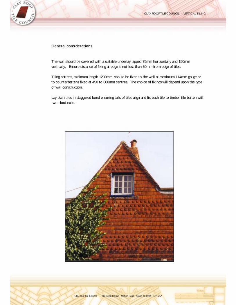
General considerations
The wall should be covered with a suitable underlay lapped 75mm horizontally and 150mmvertically. Ensure distance of fixing at edge is not less than 50mm from edge of tiles.
Tiling battens, minimum length 1200mm, should be fixed to the wall at maximum 114mm gauge or to counterbattens fixed at 450 to 600mm centres. The choice of fixings will depend upon the typeof wall construction.
Lay plain tiles in staggered bond ensuring tails of tiles align and fix each tile to timber tile batten withtwo clout nails.

Clay Roof Tile Council - Federation House - Station Road - Stoke onTrent - ST4 2SA
CLAY ROOF TILE COUNCIL - VERTICAL TILING
being nailed/screwed.withdrawal resistance in the material to which it isEnsure that length and type of fixing has adequateand plugged holes.Secure to timber pads set into bed joints or to drilledcorrosion resistant fixings.600mm centres to masonry using proprietaryFix timber counterbattens spaced at maximum
- stone masonry - old lightweight concrete blocks - dense concrete blocks(3) Wall Construction
blockwork.long) driven in askew at 450mm centres intoaluminium or mild steel cut nails (75 to 100mmFix tiling battens directly to blockwork using
- new lightweight concrete blocks(2) Wall Construction

Clay Roof Tile Council - Federation House - Station Road - Stoke onTrent - ST4 2SA
CLAY ROOF TILE COUNCIL - VERTICAL TILING
being nailed/screwed.withdrawal resistance in the material to which it isEnsure that length and type of fixing has adequateset into concrete panel.corrosion resistant fixings or nailed to timber padsmaximum 600mm centres using proprietaryFix timber counterbattens to concrete panel spaced at
- pre-cast concrete panels(5) Wall Construction
some types of new bricks)(It may be possible to fix tiling battens directly ontobeing nailed/screwed.withdrawal resistance in the material to which it isEnsure that length and type of fixing has adequateand plugged holes.Secure to timber pads set into bed joints or to drilledcorrosion resistant fixings.600mm centres to masonry using proprietaryFix timber counterbattens spaced at maximum
- old and new common brick(4) Wall Construction

Clay Roof Tile Council - Federation House - Station Road - Stoke onTrent - ST4 2SA
CLAY ROOF TILE COUNCIL - VERTICAL TILING
length required to resist predicted withdrawal loads.wire, galvanised or improved nails of sufficientFix tiling battens to vertical studding using roundmembrane.Cover plywood sheathing with approved breathable
- timber stud and plywood sheathing(7) Wall construction
render has no significant withdrawal resistance.being nailed/screwed - it should be assumed that thewithdrawal resistance in the material to which it isEnsure that length and type of fixing has adequateand plugged holes.Secure to timber pads set into bed joints or to drilledcorrosion resistant fixings.maximum 600mm centres using proprietaryFix timber counterbattens to masonry spaced at
- rendered(6) Wall Construction

Clay Roof Tile Council - Federation House - Station Road - Stoke onTrent - ST4 2SA
CLAY ROOF TILE COUNCIL - VERTICAL TILING
Rigid insulation board
Sheathing panel
Plasterboard
Construction').'Detailing and Practice' and 'Modularfurther information refer to the SCI publicationspermission of the Steel Construction Institute. For(This illustration is re-produced with the kindpredicted withdrawal loads.Fixings should be of sufficient length to resistrecommended by manufacturer.resistant self-tapping screws or proprietary fixings asSecure tiling battens to metal frame using corrosionbreathable membrane.If required, cover sheathing panel with approved
- metal frame(8) Wall construction

Clay Roof Tile Council - Federation House - Station Road - Stoke onTrent - ST4 2SA
CLAY ROOF TILE COUNCIL - VERTICAL TILING

Clay Roof Tile Council - Federation House - Station Road - Stoke onTrent - ST4 2SA
CLAY ROOF TILE COUNCIL - VERTICAL TILING
6
TILING
Setting out
The means of securing the counter battens, or, battens to the wall structure should be decidedbefore the tile battens are set out and nailed to the counter battens or the wall structure.
The setting out of battens needs to take into account the top and bottom of the wall and theopenings through it, such as windows. The top of the wall and the bottom edge are called fixedpoints and the top and bottom of each opening are also defined as fixed points. The fixed points areused to calculate the batten gauge. For example, on a wall with one window, the bottom edge of the wall and the lower edge of the window will be used to calculate the batten gauge between thesetwo points, and the bottom of the window and the top of the window are used to determine the batten gauge on this section of the wall, etc.
Starting at the bottom edge of the wall a full length tile is positioned to ensure that it just covers the wall structure below it but does not interfere the opening of any doors or windows. The position of the underside of the nibs are marked on the wall and the process repeated at various positions alongthe wall. Ideally, all the marks should be in the same horizontal plane. If they are not, one markshould be adopted as the common datum, or, a step in the tiling should be established to allow for at a feature such as an internal corner. Where a change of bottom row of tiles is planned thedifference in level should be a module of the tile gauge, which can be any dimension between 114mmand 88mm. When the line of the top of the first batten is set, it should be nailed in position.
The top of the wall has the top course (eaves / top tiles) and is set out to allow the head of the toptile, including the nibs, to fit under the eaves, or, other feature. Once this batten is in place, the lastfull tile batten can be located to allow just enough space between the bottom of the top tile battenand the top of the last full tile batten, to permit the last full tile to slide between them. Provided the tile batten is no wider than 38mm the top tile should provide adequate cover for the last full tile course.
The first fixed point should be identified, which may be a windowsill. The top tile course (eaves / top tiles) is set out to allow the head of the top tile, including the nibs, to fit under the windowsill.With the batten in place, the last full tile batten can be located to allow just enough space betweenthe bottom of the top tile batten and the top of the last full tile batten, to allow the last full tile to slide between them. Provided the tile batten is no wider than 38mm the top tile should provideadequate cover for the last full tile course. If the distance between the eaves course and the firstfixed point is relatively short it may be difficult to set a gauge that reaches the windowsill and a decision to have a longer flashing may need to be made.
Between the top of the first and the last full tile courses of any fixed points, the intermediate battenswill need to be set out to ensure that the gauge is as close to 114mm, but not less than 88mm.This is achieved by measuring the overall gauge distance and dividing it by 114mm.

Clay Roof Tile Council - Federation House - Station Road - Stoke onTrent - ST4 2SA
CLAY ROOF TILE COUNCIL - VERTICAL TILING
The answer to the sum will be a whole number and a decimal point. Whatever the whole number is,increase it by one and divide that number into the gauge distance. The answer to this sum will providethe gauge that the intermediate battens should be set out at.
The next fixed point in the wall needs to be identified and set out depending upon whether it is a bottom edge or top edge, and the battens between them gauged out equally until the last full tilebatten is reached.
All tile battens should be horizontal (level) and straight, with no sags.
Having set out and nailed all the battens the setting out of tiles on each batten should be considered.Each plain tile is 165mm wide and can have up to 3mm gap between them. The first course of tilesshould be set out to equalise all the gaps between the tiles, start and finish at corner or abutmentsand hopefully line up with the sides of window openings. Having settled on an arrangement, thebattens should be marked every third or fifth joint. To ensure that the joints are vertical dropplumb lines and mark the battens.
The eaves course of tiles are laid broken bond to the first course of tiles – this may require the useof an eaves tile and half. These can be made by cutting a full tile-and-a-half down to the same lengthas the eaves tile. The same may apply at the top tile course but is more critical as it is more visible.
At window reveals it may be necessary to finish with a cut tile-and-a-half on each course to maintain the vertical perpendicular joints. The tiles may need to be sorted to mix oversize and undersize tilestogether to ensure that an averaging out allows the perpendicular joint lines to be kept vertical. If this becomes a problem it may be necessary to trim every fifth tile down to suit.
Tiles should always be sorted and mixed from at least three pallets to ensure that the variations in shade and colour from different parts of the kiln do not give a patchy effect. Also, tiles that aretwisted may kick out in one position, but sit happily in another when tried.
It can be seen that, like brick laying, vertical tiling needs more planning during the setting out phasethan roof tiling and being more visible requires greater care in maintaining the vertical joint lines.
Because less rain and frost are likely to fall on vertical tiling the self cleaning action of the elementsare a lot slower, therefore, marks on vertical tiling may need to be cleaned off rather than waiting for the natural weathering of the tiles.

Clay Roof Tile Council - Federation House - Station Road - Stoke onTrent - ST4 2SA
CLAY ROOF TILE COUNCIL - VERTICAL TILING
Main tile design details
The following illustrations and text explain the common main tile design details that can occur on refurbishment and new work. The drawings include details at eaves, windows, abutments, internaland external corners. Tiling of gables is included and details of Winchester, Sussex and Soldier finishes are given.

Clay Roof Tile Council - Federation House - Station Road - Stoke onTrent - ST4 2SA
CLAY ROOF TILE COUNCIL - VERTICAL TILING
tiles with their nibs removed could be used.underside of the tilting fillet. Alternatively, cut plainFix a minimum 6mm thick fire resistant board to thetilting fillet.tile batten to allow the underlay to dress out over theTerminate the counterbattens just below the eavesfall.Dress the underlay over the tilting fillet to a slightthe rest of the vertical tiling.support the eaves course of tiles in the same plane aslintel (approximately 100 x 75mm) large enough toFix a shaped timber tilting fillet to the face of thefor cutting the eaves course of tiles.window sill and window head to eliminate the needSet the gauge of the vertical tiling between thetiling has been installed.window to be installed or removed after the verticalSet the eaves course above the window to allow the
(10) Vertical tiling to window head: V1
tiling to the face of an existing building.This arrangement is useful when fixing verticalthe nail holes.compromise the lap relative to the vertical joint andsection onto the coverage such that it does notWhen using a decorative flashing add the decorativesurface of the top tile.the flashing can be carefully dressed onto thethe soffit board. Once the top tiles have been nailedbatten and dress it into the top tile nib space below200mm wide, Code 4) along the face of the top tileNail the bottom edge of the lead flashing (minimum150mm.lead flashing coverage should be extended toby a minimum of 100mm. If no top tile is used theInstall a lead cover flashing to lap over the top tileboard to allow for the top tile batten to be installed.Finish battens approximately 90mm below the soffit
(9) Vertical tiling to eaves with soffit
board6mm fire resistant
thicknessdepends on counterbattenTimber tilting fillet. Size
Eaves course tile
plain tiles265 x 165mm clay
Underlay
at 114mm gauge38 x 25mm battens
at maximum 600mm centres38 x 38mm counterbattens
plain tiles265 x 165mm clay
Top course tile
over top course tiledressed minimum 100mmto face of tiling batten andMetal apron flashing fixed
at 114mm gauge38 x 25mm battens
at maximum 600mm centres38 x 38mm counterbattens
Underlay

Clay Roof Tile Council - Federation House - Station Road - Stoke onTrent - ST4 2SA
CLAY ROOF TILE COUNCIL - VERTICAL TILING
underside of the tilting fillet.Fix a minimum 6mm thick fire resistant board to thetilting fillet.tile batten to allow the underlay to dress out over theTerminate the counterbattens just below the eavesfall.Dress the underlay over the tilting fillet to a slightthe rest of the vertical tiling.support the eaves course of tiles in the same plane aslintel (approximately 100 x 75mm) large enough toFix a shaped timber tilting fillet to the face of thefor cutting the eaves course of tiles.window sill and window head to eliminate the needSet the gauge of the vertical tiling between thetiling has been installed.window to be installed or removed after the verticalSet the eaves course above the window to allow the
(12) Vertical tiling to window head: V2
rafters.detail will prevent birds from nesting between theto touch the underside of the roofing underlay. Thisventilation the timber boarding can be extended upNote: Where there is no provision for eavesnoggins nailed into the sides of the open rafters.by 19 or 25mm timber boarding, fixed to verticaltop tiles needs to be in-filled. This can be achievedThe spacing between the open rafters and above theand extend as high as possible.Set the counterbattens at maximum 600mm centresmaintained.between the rafters, the air path to the grill must beWhere the roof is ventilated using a vent traydescribed in detail (9).Fix a code 4 lead flashing to cover the top tiles astops tiles.Finish under roof eaves with a continuous course of
(11) Vertical tiling to eaves with open rafter
top course tiledressed min 150mm overto face of tiling batten andMetal apron flashing fixed
clay plain tiles265 x 165mm
at 114mm centres38 x 25mm battens
at max 600mm centres38 x 38mm counterbattens
Underlay
ventilator10 or 25mm eaves
50mm air gap
counterbatten thicknessSize dependant onTimber tilting fillet.
board6mm fire resistant
Eaves course tile
clay plain tiles265 x 165mm
at 114mm gauge38 x 25mm battens
max 600mm centres38 x 38mm counterbattens at
Underlay

Clay Roof Tile Council - Federation House - Station Road - Stoke onTrent - ST4 2SA
CLAY ROOF TILE COUNCIL - VERTICAL TILING
either side.extend a minimum of 150mm beyond the jamb onflashing should be extended to 150mm. It shouldminimum 100mm. If tops tiles are not used then theThe flashing should cover the top tiles by athe nail holes.compromise the lap relative to the vertical joint andsection onto the coverage such that it does notWhen using a decorative flashing add the decorativebe carefully dressed onto the surface of the top tiles.Once the top tiles have been fixed the flashing canInstall the lead flashing (Code 4) into the mortar bed.vertical tiling by 38 to 50mm.required. The creasing tiles should overhang themortar (1:3 Cement:sand) using dentil slips asLay the creasing tiles broken bonded bedded onthe top course of tiles to fit under the window sill.Finish battens below the window opening to allowthe external wall may be required.to run away from the window frame. A cut out inof the double course of creasing tiles to allow waterEnsure that there is a suitable fall on the top surface
(13) Vertical tiling to tiled window sill
either side.extend a minimum of 150mm beyond the jamb onflashing should be extended to 150mm. It shouldminimum 100mm. If tops tiles are not used then theThe flashing should cover the top tiles by athe nail holes.compromise the lap relative to the vertical joint andsection onto the coverage such that it does notWhen using a decorative flashing add the decorativethe top tiles.flashing can be carefully dressed onto the surface ofinstalled. Once the tops tiles have been fixed the4) to the underside of the timber sill before it isNail a lead flashing (minimum 200mm wide: Codethe top course of tiles to fit under the window sill.Finish battens below the window opening to allow
(14) Vertical tiling to timber window sill: V1
course tilesmin 100mm over topMetal flashing dressed
tilesmin 100mm over top courseMetal flashing dresssed
at 114mm centres38 x 25mm battens
Underlay
clay plain tiles265 x 165mm
Top course tiles
clay plain tiles265 x 165mm
Top course tiles
38 - 50mm
mortar bedCreasing tiles on
at 114mm centres38 x 25mm battens
Underlay
Dentil slips
�

Clay Roof Tile Council - Federation House - Station Road - Stoke onTrent - ST4 2SA
CLAY ROOF TILE COUNCIL - VERTICAL TILING
to the underside of the tilting fillet.cavity fix a minimum 6mm thick fire resistant boardWhere there is a risk of fire entering the battentilting fillet.tile batten to allow the underlay to dress out over theTerminate the counterbattens just below the eavesfall.Dress the underlay over the tilting fillet to a slightthe rest of the vertical tiling.support the eaves course of tiles in the same plane aslintel (approximately 100 x 75mm) large enough toFix a shaped timber tilting fillet to the face of the
(16) Vertical tiling eaves
either side.extend a minimum of 150mm beyond the jamb onflashing should be extended to 150mm. It shouldminimum 100mm. If tops tiles are not used then theThe flashing should cover the top tiles by athe nail holes.compromise the lap relative to the vertical joint andsection onto the coverage such that it does notWhen using a decorative flashing add the decorativecarefully dressed onto the surface of the top tiles.the tops tiles have been fixed the flashing can bebatten and dress it into the top tile nib space. Once200mm wide: Code 4) along the face of the top tileNail the bottom edge of the lead flashing (minimumthe top course of tiles to fit under the window sill.Finish battens below the window opening to allow
(15) Vertical tiling to timber window sill: V2
�
Bead of mastic
clay plain tiles265 x 165mm
Underlay
at max 600mm centres38 x 38mm counterbattens
at 114mm gauge38 x 25mm battens
clay plain tiles265 x 165mm
Eaves course tile
Timber tilt fillet
at max 600mm centres38 x 38mm counterbattens
at 114mm gauge38 x 25mm battens
Underlay
top course tiledressed min 150mm overto face of tiling batten andMetal apron flashing fixed

Clay Roof Tile Council - Federation House - Station Road - Stoke onTrent - ST4 2SA
CLAY ROOF TILE COUNCIL - VERTICAL TILING
possible.Cut tiles neatly and as close to the main roof tiling asprovide support for raking cut vertical eaves tiles.Fix a timber tilt batten to the rake of the roof tiling tovertical tiling.secured behind the battens/counterbattens of theinserted between each course of roof tiles should beThe vertical upstands of the Code 3 lead soakersunderlay.by a minimum 50mm and overlap by verticalExtend underlay on main roof vertically up the wall
(18) Vertical tiling junction with side abutment
(See details 37 to 43 for gable verge treatments)undercloak.Cut tiles neatly to form detail at junction with vergetiles.undercloak to provide fixing for cut vertical gableFix timber batten in line with rake of vergeto 50mm beyond face of vertical tiling.Ensure that verge undercloak extends a minimum 38underlay by a minimum 150mm.Extend underlay on main roof to overlap vertical
(17) Vertical tiling junction with verge
gable cutting details)Tiles cut to rake (see
Underlay
at 114mm gauge38 x 25mm battens
at max 600mm centres38 x 38mm counterbattens
38 - 50mm
Underlay
at 114mm gauge38 x 25mm battens
clay plain tiles265 x 165mm
Tiles cut as required
Metal soakers
by min 50mmTurn up underlay
at max 600mm centres38 x 38mm counterbattens
lowest cornerTimber tilt block at
Clay Roof Tile Council - Federation House - Station Road - Stoke onTrent - ST4 2SA
CLAY ROOF TILE COUNCIL - VERTICAL TILING
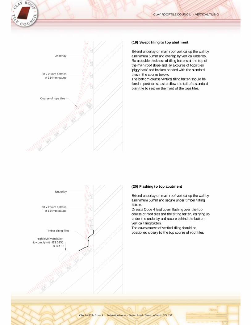
positioned closely to the top course of roof tiles.The eaves course of vertical tiling should bevertical tiling batten.under the underlay and secure behind the bottomcourse of roof tiles and the tilting batten, carrying upDress a Code 4 lead cover flashing over the topbatten.a minimum 50mm and secure under timber tiltingExtend underlay on main roof vertical up the wall by
(20) Flashing to top abutment
plain tile to rest on the front of the tops tiles.fixed in position so as to allow the tail of a standardThe bottom course vertical tiling batten should betiles in the course below.'piggy back' and broken bonded with the standardthe main roof slope and lay a course of tops tilesFix a double thickness of tiling battens at the top ofa minimum 50mm and overlap by vertical underlay.Extend underlay on main roof vertical up the wall by
(19) Swept tiling to top abutment
& BR F2to comply with BS 5250
High level ventilation
Timber tilting fillet
at 114mm gauge38 x 25mm battens
Underlay
Course of tops tiles
at 114mm gauge38 x 25mm battens
Underlay

Clay Roof Tile Council - Federation House - Station Road - Stoke onTrent - ST4 2SA
CLAY ROOF TILE COUNCIL - VERTICAL TILING
maintained.minimum 5000 sq mm per metre run air path isthe top course of roof tiles and ensure that aPosition the eaves course of vertical tiling closely tobehind the bottom vertical tiling batten.batten, carrying up under the underlay and secureproprietary abutment ventilator and the timber tiltingDress a Code 4 lead cover flashing over thewall.minimum 10mm gap at the junction with the verticalCut back the underlay on the main roof to provide a
(21) Ventilated flashing to top abutment
10mm minimum gap
(supplied by roof tile manufacturer)proprietary abutment ventilator
Lead flashing dressed over
Timber tilting fillet
at 114mm gauge38 x 25mm battens
Underlay

Clay Roof Tile Council - Federation House - Station Road - Stoke onTrent - ST4 2SA
CLAY ROOF TILE COUNCIL - VERTICAL TILING
tiles to maintain minimum headlap of 65mm.Establish the correct number of courses of mansardminimum 150mm.Lap the roof underlay over the mansard underlay bybetween the rafters.from eaves to ridge where insulation is positionedEnsure that a clear ventilation path is maintained
(23) Mansard roof with mansard tiles
locations.Clip the bottom edge of the flashing in exposed-200mm up the tilt batten.tiles by minimum 150mm and extending 150Dress cover flashing over the top course mansardmansard underlay under tilt batten.Lap roof underlay over the lead welt and securebetween the rafters.from eaves to ridge where insulation is positionedEnsure that a clear ventilation path is maintainedcourse of tiles.support for Code 4 lead cover flashing and eavesFix continuous timber tilt batten at eaves to provide
(22) Flashing to mansard roof
Underlay
at 114mm gauge38 x 25mm battens
Mansard tiles
minimum150mm
Underlay
at 114mm gauge38 x 25mm battens
over flashingUnderlay taken
Welt
�

Clay Roof Tile Council - Federation House - Station Road - Stoke onTrent - ST4 2SA
CLAY ROOF TILE COUNCIL - VERTICAL TILING
minimum 100mm.Dress lead cover flashing over the top course tiles byDress lead cover flashing over ventilator.metre high level ventilation to the main roof space.Install strip ventilator to provide 10,000 sq mm perwith mono ridge tile.Fix Code 4 lead cover flashing to fascia and coverabove top course vertical tiles.Provide continuous timber fascia located directly
V2(25) Vertical tiling junction with monopitch roof:
main roof space.5000 sq mm per metre high level ventilation to theInstall vent tiles spaced to provide the equivelant ofminimum 100mm.Dress lead cover flashing over the top course tiles bywith mono ridge tile.Fix Code 4 lead cover flashing to fascia and coverabove top course vertical tiles.Provide continuous timber fascia located directly
V1(24) Vertical tiling junction with monopitch roof:
Underlay
at 114mm gauge38 x 25mm battens
top course tileminimum 100mm overMetal flashing dressed
20mm
ventilator strip10mm over fascia
over ventilatorMetal flashing dressed
Underlay
at 114mm gauge38 x 25mm battens
over top course tiledressed min 100mmMetal apron flashing
with BS 5250 & BR F2High level ventilation to comply

Clay Roof Tile Council - Federation House - Station Road - Stoke onTrent - ST4 2SA
CLAY ROOF TILE COUNCIL - VERTICAL TILING
minimum 6mm deep when fixed to timber framing.Note: If counterbattens are used, these need only betiles and terminated with a welt.wide, turned into a rebate just behind the face of theFix a vertical lead flashing, approximately 200mmshould be avoided.courses up the external corner. Cutting of theseHanded external angle tiles are fixed in alternatecutting to a half tile module.distance in increments of 82.5mm will minimise tileframe should ideally be 290mm. Reducing thistile batten on the side of the dormer to the windowTo avoid tile cutting the distance from the face of the
(27) Vertical tiling to dormer side
batten.prevent the end nail fixing from splitting the tileapproximately 20mm in from the end of the batten toThe first counterbatten should be fixedalternate courses.the reveal with a full tile and a tile and half intiles and terminated with a welt. Finish tiling againstwide, turned into a rebate just behind the face of theFix a vertical lead flashing approximately 200mmface of the wall.exact position of the window frame relative to thereveal. The size of the reveal will depend upon theCover the ends of the vertical tiling with a timber
side(26) Vertical tiling junction with timber frame
240m
m
290m
m
at 114mm gauge38 x 25mm battens
Underlay
PLAN VIEW
at max 600mm centres38 x 38mm counterbattens
Internal cill
Timber reveal
External cill into rebateMetal flashing fixed
25mm plywood
PLAN VIEW
Plaster board and skim
Underlay
Insulation
in alternate courses90 degree external anglesLeft and right hand
75 x 50mm timber studding
at 114mm gauge38 x 25mm battens
into rebateMetal flashing fixed
Clay Roof Tile Council - Federation House - Station Road - Stoke onTrent - ST4 2SA
CLAY ROOF TILE COUNCIL - VERTICAL TILING
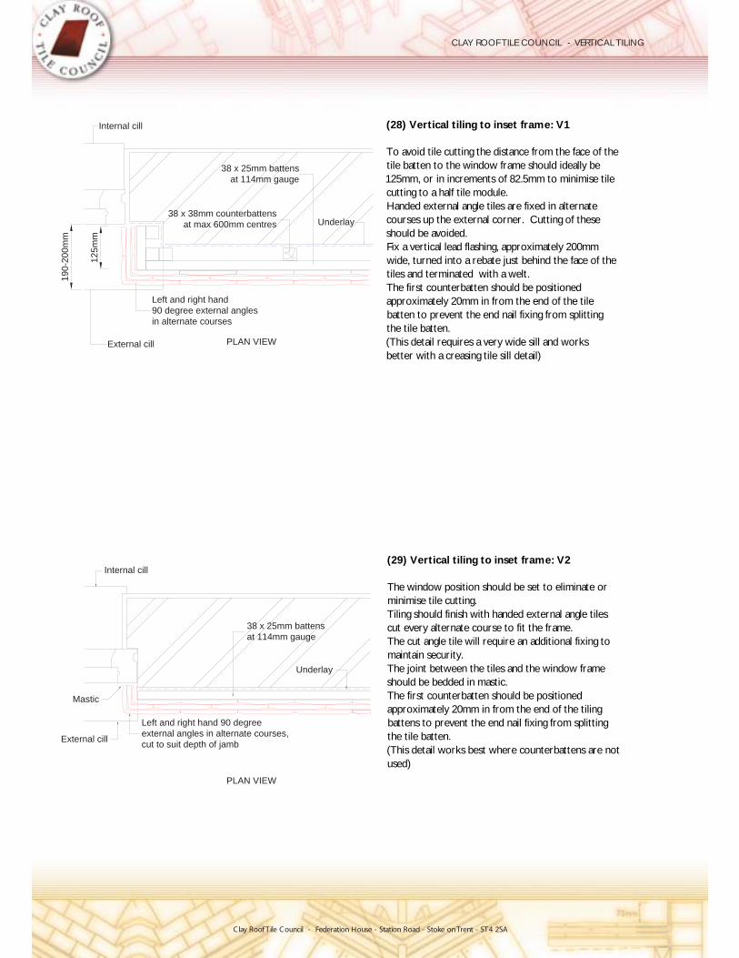
better with a creasing tile sill detail)(This detail requires a very wide sill and worksthe tile batten.batten to prevent the end nail fixing from splittingapproximately 20mm in from the end of the tileThe first counterbatten should be positionedtiles and terminated with a welt.wide, turned into a rebate just behind the face of theFix a vertical lead flashing, approximately 200mmshould be avoided.courses up the external corner. Cutting of theseHanded external angle tiles are fixed in alternatecutting to a half tile module.125mm, or in increments of 82.5mm to minimise tiletile batten to the window frame should ideally beTo avoid tile cutting the distance from the face of the
(28) Vertical tiling to inset frame: V1
used)(This detail works best where counterbattens are notthe tile batten.battens to prevent the end nail fixing from splittingapproximately 20mm in from the end of the tilingThe first counterbatten should be positionedshould be bedded in mastic.The joint between the tiles and the window framemaintain security.The cut angle tile will require an additional fixing tocut every alternate course to fit the frame.Tiling should finish with handed external angle tilesminimise tile cutting.The window position should be set to eliminate or
(29) Vertical tiling to inset frame: V2
PLAN VIEW
Left and right hand 90 degreeexternal angles in alternate courses,cut to suit depth of jamb
External cill
Mastic
38 x 25mm battensat 114mm gauge
Underlay
Internal cill
190-
200m
m
125m
m
PLAN VIEWExternal cill
Left and right hand90 degree external anglesin alternate courses
Underlay
38 x 25mm battensat 114mm gauge
38 x 38mm counterbattensat max 600mm centres
Internal cill

Clay Roof Tile Council - Federation House - Station Road - Stoke onTrent - ST4 2SA
CLAY ROOF TILE COUNCIL - VERTICAL TILING
vertical tiling, such as French windows)the window that starts below the eaves line of the(This detail works best where there is a short sill todoes not come in contact with the timber batten end.short of the end of the tiling to ensure that the mortarThe tile battens should be cut approximately 50mmthe face of the tiling battens is not critical.tiles. The distance from the face of the windows toreveals rendered to cover the ends of the verticalthe window opening and the window openingthe tiling traditionally has been finished flush withline, and is installed from the inside of the building,Where the window frame is set back from the wall
finish(30) Vertical tiling to frame with pointed verge
Underlay
PLAN VIEW
at 114mm gauge38 x 25mm battens
Internal cill
Flush pointed
External cill
Clay Roof Tile Council - Federation House - Station Road - Stoke onTrent - ST4 2SA
CLAY ROOF TILE COUNCIL - VERTICAL TILING
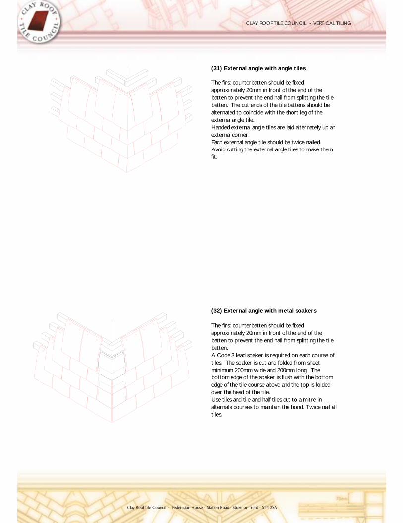
tiles.alternate courses to maintain the bond. Twice nail allUse tiles and tile and half tiles cut to a mitre inover the head of the tile.edge of the tile course above and the top is foldedbottom edge of the soaker is flush with the bottomminimum 200mm wide and 200mm long. Thetiles. The soaker is cut and folded from sheetA Code 3 lead soaker is required on each course ofbatten.batten to prevent the end nail from splitting the tileapproximately 20mm in front of the end of theThe first counterbatten should be fixed
(32) External angle with metal soakers
fit.Avoid cutting the external angle tiles to make themEach external angle tile should be twice nailed.external corner.Handed external angle tiles are laid alternately up anexternal angle tile.alternated to coincide with the short leg of thebatten. The cut ends of the tile battens should bebatten to prevent the end nail from splitting the tileapproximately 20mm in front of the end of theThe first counterbatten should be fixed
(31) External angle with angle tiles
�

Clay Roof Tile Council - Federation House - Station Road - Stoke on Trent - ST4 2SAClay Roof Tile Council - Federation House - Station Road - Stoke onTrent - ST4 2SA
CLAY ROOF TILE COUNCIL - VERTICAL TILING
fit.Avoid cutting the internal angle tiles to make themEach internal angle tile should be twice nailed.internal corner.Handed internal angle tiles are laid alternately up anexternal angle tile.alternated to coincide with the short leg of thebatten. The cut ends of the tile battens should bebatten to prevent the end nail from splitting the tileapproximately 20mm in front of the end of theThe first counterbatten should be fixed
(33) Internal angle with angle tiles
tiles.alternate courses to maintain the bond. Twice nail allUse tiles and tile and half tiles cut to a mitre inover the head of the tile.edge of the tile course above and the top is foldedbottom edge of the soaker is flush with the bottomminimum 200mm wide and 200mm long. Thetiles. The soaker is cut and folded from sheetA Code 3 lead soaker is required on each course ofbatten.batten to prevent the end nail from splitting the tileapproximately 20mm in front of the end of theThe first counterbatten should be fixed
(34) Internal angle with metal soakers
Clay Roof Tile Council - Federation House - Station Road - Stoke onTrent - ST4 2SA
CLAY ROOF TILE COUNCIL - VERTICAL TILING
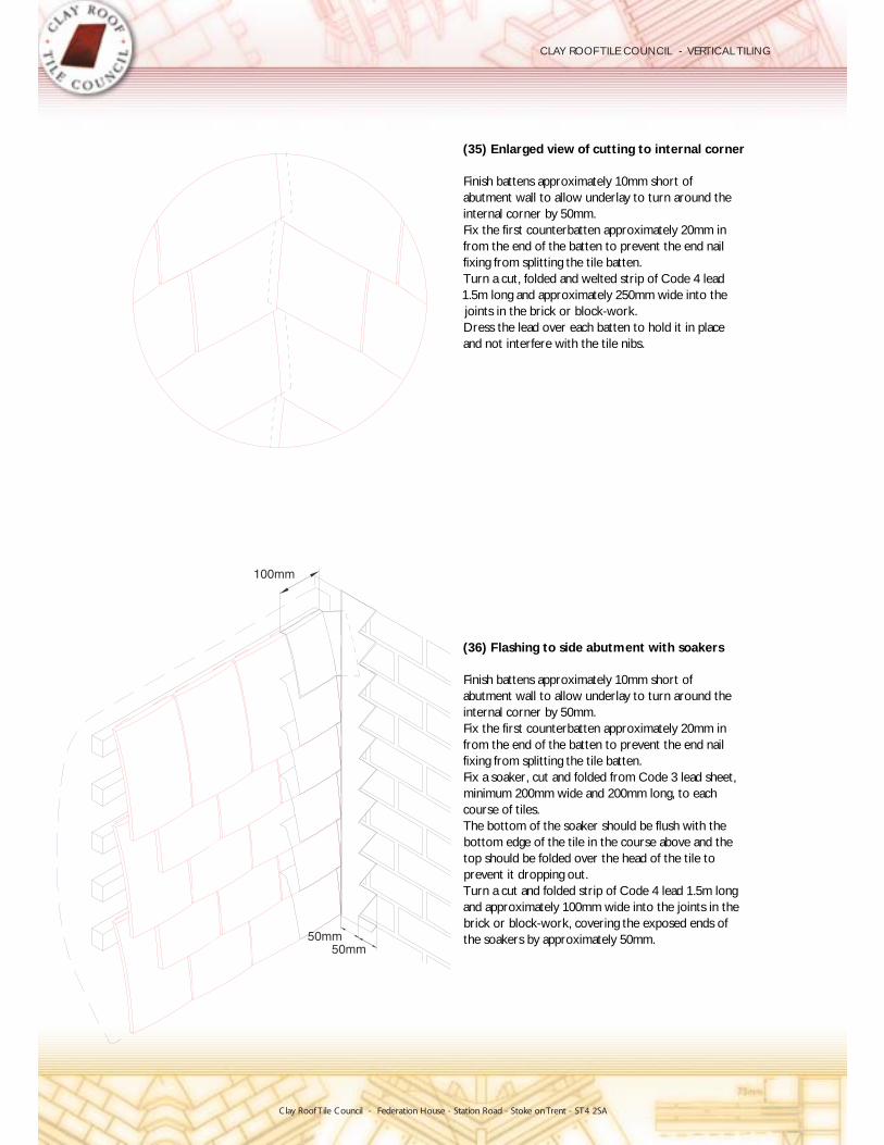
the soakers by approximately 50mm.brick or block-work, covering the exposed ends ofand approximately 100mm wide into the joints in theTurn a cut and folded strip of Code 4 lead 1.5m longprevent it dropping out.top should be folded over the head of the tile tobottom edge of the tile in the course above and theThe bottom of the soaker should be flush with thecourse of tiles.minimum 200mm wide and 200mm long, to eachFix a soaker, cut and folded from Code 3 lead sheet,fixing from splitting the tile batten.from the end of the batten to prevent the end nailFix the first counterbatten approximately 20mm ininternal corner by 50mm.abutment wall to allow underlay to turn around theFinish battens approximately 10mm short of
(36) Flashing to side abutment with soakers
and not interfere with the tile nibs.Dress the lead over each batten to hold it in placejoints in the brick or block-work.1.5m long and approximately 250mm wide into theTurn a cut, folded and welted strip of Code 4 leadfixing from splitting the tile batten.from the end of the batten to prevent the end nailFix the first counterbatten approximately 20mm ininternal corner by 50mm.abutment wall to allow underlay to turn around theFinish battens approximately 10mm short of
(35) Enlarged view of cutting to internal corner
�
100mm
50mm50mm

Clay Roof Tile Council - Federation House - Station Road - Stoke onTrent - ST4 2SA
CLAY ROOF TILE COUNCIL - VERTICAL TILING
and spot bedded.shaped piece of tile which is both mechanically fixedThe finish at the apex is best achieved using ajoint above a joint when finishing at the apex.exact half bond and commenced so as to avoid aMark out the gable end wall so that tiling is fixed to
(37) Setting out for vertical tiling to gable ends

Clay Roof Tile Council - Federation House - Station Road - Stoke onTrent - ST4 2SAClay Roof Tile Council - Federation House - Station Road - Stoke on Trent - ST4 2SA
CLAY ROOF TILE COUNCIL - VERTICAL TILING
90 degrees)that the vertical tiling meets the undercloak/soffit atfirst tile-and-a-half tile adjacent to the next tile; ie so(An alternative method is to have the cut edge of theside laps are less than 55mm.Use lead soakers, minimum 200 x 200mm, whereto avoid narrow cuts.and tile-and-a-half tiles should be used as necessaryThe second cut tile in each course will vary in size
table for correct angle of cut)(Seeidentical shape and size to give uniformity.cut tiles abutting the undercloak/soffit should be ofUse tile-and-a-half tiles in each course of tiling. Alltile to provide extra width.Form the end under-eaves tile from a tile-and-a-half
Winchester cutting: V1(39) Vertical tiling junction with roof verge -
drawing.or a slot formed with a cutting disk as shown on theWhere possible, a second nail hole should be drilledneatly cut to fit close to the undercloak/soffit.Use tile-and-a-half tiles in each course of tiling,
(38) Vertical tiling junction with roof verge
60˚
35˚
at 114mm gauge38 x 25mm battens
minimum
requiredMetal soaker where
Eaves tile undercourse
at 114mm centres38 x 25mm battens
Eaves tile undercourse
to suit coursingTile-and-a-half tile, cut
and nailed into parallel battenTile-and-a-half tile, pre-cut
minimum
Clay Roof Tile Council - Federation House - Station Road - Stoke onTrent - ST4 2SA
CLAY ROOF TILE COUNCIL - VERTICAL TILING
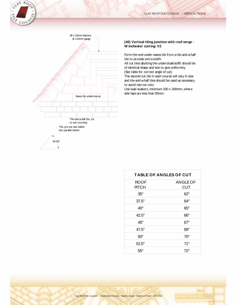
72°55°
67°
70°
69°
45°
47.5°
50°
52.5° 71°
65°
66°
40°
42.5°
64°37.5°
62°35°
CUTANGLE OF
PITCHROOF
TABLE OF ANGLES OF CUT
side laps are less than 55mm.Use lead soakers, minimum 200 x 200mm, whereto avoid narrow cuts.and tile-and-a-half tiles should be used as necessaryThe second cut tile in each course will vary in size
table for correct angle of cut)(Seeof identical shape and size to give uniformity.All cut tiles abutting the undercloak/soffit should betile to provide extra width.Form the end under-eaves tile from a tile-and-a-half
Winchester cutting: V2(40) Vertical tiling junction with roof verge -
45-55°
into parallel battenTile, pre-cut and nailed
to suit coursingTile-and-a-half tile, cut
Eaves tile undercourse
at 114mm gauge38 x 25mm battens
Clay Roof Tile Council - Federation House - Station Road - Stoke onTrent - ST4 2SA
CLAY ROOF TILE COUNCIL - VERTICAL TILING
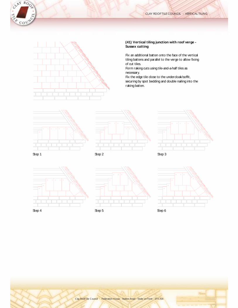
raking batten.securing by spot bedding and double nailing into theFix the edge tile close to the undercloak/soffit,necessary.Form raking cuts using tile-and-a-half tiles asof cut tiles.tiling battens and parallel to the verge to allow fixingFix an additional batten onto the face of the vertical
Sussex cutting(41) Vertical tiling junction with roof verge -
Step 6Step 5Step 4
Step 3Step 2Step 1

Clay Roof Tile Council - Federation House - Station Road - Stoke onTrent - ST4 2SA
CLAY ROOF TILE COUNCIL - VERTICAL TILING
Eaves tiles
Standard tiles
Cover flashing
Eaves tiles
course tiles' nailholes and to the apex.A cover flashing can be used to cover the soldierdamage.Spot bedding is recommended to prevent windproperly on their nibs.should be positioned to allow the tiles to hangclose to the undercloak/soffit. The raking battenscourse of tiles/eaves tiles to raking battens fixedpitch can be weathered by nailing a double soldierVertical tiling beneath verges less than 35° roof
(43) Double soldier course
and to the apex.weathering over the soldier course tiles' nailholesA cover flashing can be used to provide extradamage.Spot bedding is recommended to prevent windnibs.positioned to allow the tiles to hang properly on theirundercloak/soffit. The raking batten should beeaves tiles to a raking batten fixed close to thepitch can be weathered by nailing a soldier course ofVertical tiling beneath verges less than 35° roof
(42) Soldier course

Clay Roof Tile Council - Federation House - Station Road - Stoke onTrent - ST4 2SA
CLAY ROOF TILE COUNCIL - VERTICAL TILING
Decorative tiling design details
The following drawings illustrate some of the range of decorative finishes that are available. The drawings only deal with the pysical shape of the tiles and do not reflect the wide range of coloursthat are available.
Club & FishtailPointed & StepBullnose & Fishtail
Pointed & BullnoseFishtailspade)Bullnose (also called Beavertail or
ClubPointed (also called Arrowhead)
(44) Vertical tiling patterns
Step

Clay Roof Tile Council - Federation House - Station Road - Stoke onTrent - ST4 2SA
CLAY ROOF TILE COUNCIL - VERTICAL TILING
the lap relative to the vertical joint and the nail holes.onto the coverage such that it does not compromiseThe decorative section of flashing should be addedused coverage should be extended to 150mm.coverage of the flashing is 100mm. If no top tile isWhere a top course tile is used the minimum
(46) Decorative flashings
in accordance with manufacturers' instructions.Joints may be left dry or can be bedded and pointedtile.Lay tiles in broken bond fashion and twice nail eachwith recommended fixings.the design of the product and secure to groundworkFix 38 x 25mm tiling battens to specified gauge for
(45) Mathematical tiling

Clay Roof Tile Council - Federation House - Station Road - Stoke onTrent - ST4 2SA
CLAY ROOF TILE COUNCIL - VERTICAL TILING
Pipe fixing details
There are a limited number of acessories that can be fixed through vertical tiling but the examplesgiven in the attached drawings illustrate the possible fixing methods.
Secure rainwater pipe clip to bracket.screw.Fix pipe clip back plate to timber block with suitablehole cut in tiling.Form Code 4 lead flashing to fixing block throughcounterbattens or supports prior to tiling.top of an extra tiling batten spanning at least twoProvide suitable 265mm wide timber block fixed on
(48) Pipe fixing through vertical tiling: V2
Secure rainwater pipe clip to bracket.plate to tile batten with suitable screw.Insert spacer tube through tile and fix pipe clip backexample 15mm copper tube).Drill hole through tile to suit tube diameter (for
(47) Pipe fixing through vertical tiling: V1
Spacer tube
Pipe clip
to tile battenPipe clip backplate fixed
Hole drilled through tile
�
�
Pipe clip
Metal flashing
to timber blockPipe clip backplate fixed
Timber block 265mm long
two counterbattensExtra batten spaning

Clay Roof Tile Council - Federation House - Station Road - Stoke onTrent - ST4 2SA
CLAY ROOF TILE COUNCIL - VERTICAL TILING
7
REPAIR AND MAINTENANCE
When correctly installed in accordance with the manufacturer’s recommendations the finished wallshould give trouble-free performance for the guaranteed life of the product without the need forextensive maintanance or repair.
Basic precautions
A periodic visual inspection of the wall should be undertaken to check that tiles have not been damaged and that moss and lichen growths that could affect the flow of water off the wall areremoved. Any openings or ventilation grills should be checked and cleared if blocked. Guttersshould be cleared of debris and leaves.
Access to wall
Care should be taken to avoid access to the wall by window cleaners, aerial installers, etc. withoutadequate access equipment.
If ladders are used for temporary access to windows or roof, the ladders should not rest against thetiles without a suitable packing material to protect the tiles against breakage.
Mobile access platforms are suitable where the repair work is not extensive. All mobile tower platforms should be constructed to the requirements of BS 7171 : 1989 (power operated) or BS 1139 : Part 3 : 1994 and BS 1139 : Part 5 : 1990 (mobile working towers).
Scaffolds should be used where the repair work is extensive. All independently tied scaffold shouldconform to BS 5973 : 1993.
Repair and replacement of broken tiles
To successfully repair damaged vertical tiling, the tiles directly above the damaged tiles should be stripped out from the top down in a vee. The damaged tiles can then be removed and replaced. When fixing replacement tiles the fixings should go into fresh timber, or, larger diameter nails, or, screws, can be used.
Major Repairs
Where the condition of the roof of a historic building is poor enough to warrant stripping and re-tiling, it is acknowledged that English Heritage and local authority conservation officers like to see sound tiles salvaged and re-used on the same roof, with any deficiencies made up with new tileswhich match the existing. Members of CRTC are in the unique position of being able to assist in the provision of new tiles to match historic patterns and thereby ensure the success of such projects.When recovering, it is advisable to photograph the roof prior to stripping, to ensure that theexisting details are properly followed.

Clay Roof Tile Council - Federation House - Station Road - Stoke onTrent - ST4 2SA
CLAY ROOF TILE COUNCIL - VERTICAL TILING
Stripping should be carried out carefully to ensure that any sound existing tiles remain undamagedso that they can be sorted according to type, size and thickness and stored for re-use. When assessingexisting tiles for reuse, their likely further life should be carefully considered.
Retiling should be carried out using sound tiles salvaged from the roof, with any deficiencies made up with suitable replacement tiles, matching the existing ones in type, size, thickness, colour, and texture. The selection of existing tiles for reuse should be carried out with great care to ensure that they will have a significant life in relation to the new material. If the direct equivalent of the original tiles are not readily available from stock, member companies of CRTC can supply to order specially made tiles for such projects.

Clay Roof Tile Council - Federation House - Station Road - Stoke onTrent - ST4 2SA
CLAY ROOF TILE COUNCIL - VERTICAL TILING
8
HEALTH AND SAFETY
The recommendations in the HSE guidance note HSG 336 : ‘Health and Safety in Roofwork’ and the National Federation of Roofing Contractor’s safe wind speed recommendations should be followed.
A safety method statement should be prepared that includes :
the working positions at the vertical face;access routes;how falls are to be prevented;how the danger from falling materials to those at work and to the public is to be controlled;how risks to health will be controlled;how other risks identified at the planning stages are to be controlled;what equipment will be required;what competence and training will be needed;who will supervise the job ‘on-site’;how changes will be made to the work without prejudicing safe working; who will monitor that the safe system of work is operating properly.
The most relevant legislation for construction health and safety is:
The Health and Safety at Work etc. Act, 1974;The Management of Health and Safety at Work Regulations, 1992; The Construction (Health, Safety and Welfare) Regulations 1996; The Construction (Design and Management) Regulations 1994;The Construction (Head Protection) Regulations, 1989;The Construction (Lifting Operations) Regulations 1961.
Tile cutting
When cutting tiles precautions should be taken not to inhale the dust. Wet cutting is preferred but if dry cutting is undertaken an appropriate mask should be worn. The mask suppliers’recommendations should be followed.
6 See References & Bibliography

Clay Roof Tile Council - Federation House - Station Road - Stoke onTrent - ST4 2SA
CLAY ROOF TILE COUNCIL - VERTICAL TILING
Appendix A
MATERIAL SPECIFICATIONS
Tiles and fittings
Plain clay tiles and fittings should comply with BS EN 1304. It should be noted that hand made tilesand second hand tiles, which may not comply with the dimensional requirements of BS EN 1304,may be used for vertical tiling.
Accessories
Accessories, e.g., ventilation tiles, proprietary soakers, outlets, edge trims, proprietary flashings etc., may have third party approval for the design and performance.
Lead
Where lead is exposed to weathering it should be code 4 BS 1178 as a minimum and where it is protected it may be code 3. Surfaces of all exposed lead should be treated with patination oil toprevent lead oxide staining of the tiles.
Mortar
Where mortar is used as a filler a mix of 1 part cement to 4 parts sand would be satisfactory, but,where the mortar is used to fix tiles, a mix of 1 part cement to 3 parts sand should be used. Mostsands conforming to BS 1200 are suitable. However, a test method for measuring the tensile bond strength of the mortar is given in BS 5534.
Adhesives
Where adhesives are used the adhesive manufacturer’s recommendations for the material with claytiles should be followed.
Underlays
Underlays installed on or above boarding or plywood sheathing should be permeable to water vapour to prevent the formation of condensation between the underlay and the wood support. Aminimum permeability of 0.36 g / m2 per 24 hours when tested in accordance with BS 4016 at 25 ºCand relative humidity 75 %. Bituminous underlays should be reinforced.
Underlays installed on or above brick or blockwork should conform to types 1F or 5U as specified in BS 747, or, that specified for boarding and plywood given above.

Clay Roof Tile Council - Federation House - Station Road - Stoke onTrent - ST4 2SA
CLAY ROOF TILE COUNCIL - VERTICAL TILING
Battens and counter battens
Timber species
The timber species should comply with type A or type B as specified in BS 5534 and should betreated where the Building Regulations and bye-laws require protection against the HouseLonghorn beetle. Suitable treatments are given in BS 5268 : part 5.
NOTE : Where there is a risk that timber moisture content will be greater than 22%, treatments that react with metal fixings should be avoided, e.g., copper chrome arsenate which reacts with aluminium.
Batten and counter batten sizes
Up to 600mm support centres the :
Counter batten sizes should be 38mm by 38mm minimum;Batten sizes should be 38 (+3 / -3) mm by 25 (+ 3 /-0) mm.
Notes : In timber frame structures the counter batten sizes can be reduced.
Where counter battens are used on timer frame constructions the counterbattens need onlybe minimum 6mm deep. They must be placed directly above and secured into the timberframing.
Where batten bounce is a problem on brick structures counter battens used at 450mmcentres may prevent the problem.
Fasteners
Nails for tiles and fittings
Clout head nails complying with BS 1202 part 1 (stainless steel), part 2 (copper), part 3 (aluminium) may be used.
Aluminium clout head nails of 3.35mm diameter may be used and they should be a minimumof 38mm long. Stainless steel or copper clout head nails of 2.65mm diameter may also be used.
Improved nails (annular, ring shank and drive screws) or screws may be used where the windload calculation indicates that smooth shank nails will not meet the requirement. Nail ‘pull-out’ resistance figures can be found in BS 5268.
Steel, or, galvanised nails should not be used for nailing tiles.

Clay Roof Tile Council - Federation House - Station Road - Stoke onTrent - ST4 2SA
CLAY ROOF TILE COUNCIL - VERTICAL TILING
Nails and fasteners for securing battens to counter battens
Round wire nails complying with BS 1202 part 1, part 7 or hot dipped galvanised or stainlesssteel should be used. The nails are usually 2.65mm, or, 3.55mm in diam eter a nd 65mm long,however, they may be longer to meet the requirements for wind loading.
For exposed conditions improved nails, screws or helical fixings may be required.
Nails and fasteners for securing battens and counter battens to the wall
Cut clasp nails (BS 1202 part 1) may be used with aerated concrete blocks and the lengthshould be the thickness of the timber to be fixed plus the recommended penetration, typically,50mm to 75mm. Wall anchors shou ld be used for dense concrete b locks, brick work andprecast concrete panels and the length and diameter of the anchor should be in accordancewith the fixing manufacturers recommendations.
Flashing and junctions
Where required, metal flashing and junctions should be fixed with copper or stainless steel nails. The size of the nails should be in accordance with the recommendations given in the Lead Sheet Manual , volume 5 1. Aluminium nails must not be used to fix lead flashing.
Flashing in exposed locations may need to be clipped and this should be in accordance with Lead Sheet Manual recommendations.
Recommendations for copper and stainless steel to be added (contact to the copper and zincdevelopment associations to be made).
5 See Re ferences & Bibl iography
5

Clay Roof Tile Council - Federation House - Station Road - Stoke onTrent - ST4 2SA
CLAY ROOF TILE COUNCIL - VERTICAL TILING
Appendix B
WIND UPLIFT CALCULATIONS
Introduction
BS 5534: Part 1: 2003: The British Standard Code of practice for Slating and tiling, recommends that, where plain tiles are used for vertical tiling, all tiles should be twice nailed, using nails not less than2.65mm in diameter and of a length which gives at least 15mm penetration into the tile batten.
However, it must be stressed that there will be situations where fixing the tiles at this minimumrequirement may not be enough to prevent tiles being dislodged in high winds.
The following calculations can therefore be used to establish whether a higher level of fixing isrequired.
These calculations must not be used to justify using a lower level of fixing than that which is recommended in BS 5534.
The following sections, A and B, show how the predicated wind uplift force for a particular projectand its location can be determined.
The calculations in Section C provide the resistance to this wind force of the tiles, battens,counterbattens and their fixings.
Section D gives an example of these calculations.
A To Determine Wind Uplift Force - A summary of calculations according torequirements of BS 6399
1. Basic equation
It is assumed the force that the wind could exert directly on the windward side of the building willact as a vacuum force on the lee side of the building and it is this vacuum that causes the tiles to liftoff the roof. It is assumed that the uplift force is equal to the force applied to the windward side of the building and conventionally this is given a negative sign.
Force = Pressure x Area
Force (Ft) = dynamic pressure of wind (qs) x pressure coefficient (Cpe - Cpi) x area (At)
The dynamic pressure of the wind is proportional to the wind speed and the pressure coefficientconverts the wind speed to a pressure. The coefficients have been derived from wind tunnel testing where wind speed and pressure generated were measured.

Clay Roof Tile Council - Federation House - Station Road - Stoke onTrent - ST4 2SA
CLAY ROOF TILE COUNCIL - VERTICAL TILING
Cp i is the internal pressure coefficient
Therefore,
Ft = qs (Cpe -Cpi) At
Where,
qs = 0.613 Ve2
and,0.613 is an experimentally determined constant and Ve is the effective wind velocity
and, Ve = Vb . Sa . Sb . Sd . Ss . Sp
Therefore,
Ft = 0.613 [Vb .Sa . Sb . Sd . Ss . Sp ]2 (Cpe -Cpi) At
where,
Vb is the site wind speed which is obtained from the 50 year return wind speed map of theUK (given in BS 6399 and BS 5534).
Sa is a factor that takes the altitude into consideration and,
where the topography is not significant, Sa = 1 + - s, and
where the topography is significant, Sa = 1 + - s, or, 1 + 0.001 - T + 1.2 S, (the greater value is taken).
s is the site altitudeT is the base altitude of the topographical feature s the slope
S is a factor that allows for the position of the building on the slope
Significant topography, the calculation methods for T, and S are described in BS 6399.
Sb is a factor that takes into consideration the effective height of the building, whether thebuilding is in a town or country environment and the distance from the sea or large open expanse of water. The method of establishing the effective height and the related values of Sb
are given in BS 6399.
Cpe is the external pressure coefficient
Ɋ
Ɋ
Ɋ

Clay Roof Tile Council - Federation House - Station Road - Stoke onTrent - ST4 2SA
CLAY ROOF TILE COUNCIL - VERTICAL TILING
Sd is a wind direction factor and usually given the value 1 which allows for wind from alldirections. A lower figure can be entered if there is a single or predominant wind direction.
Ss is a wind season factor which is usually set at the value 1 which allows for wind at all timesof the year. A lower figure can be used if there is a significant variation in the wind loads inthe different seasons.
Sp is a probability factor which is assumed to be 1 if the expected wind return rate is once in fifty years. Other figures can be used if different return periods are anticipated.
Cp e is the external pressure coefficient and values can be obtained from BS 6399.
Cp i is the internal pressure coefficient and the values can be obtained from BS 6399.
At is the exposed area of the tile and is usually calculated from the product of the battengauge (Ga) the cover width (B) of the tiles.
B Modifications to calculation method introduced by BS 5534
1. The Cpe - Cpi is replaced by Cpt which can be used for most common applications and when the values of Cpt were calculated from BS 6399 they were modified to ensure thatthe values obtained were consistent with the values obtained from the previous CP3 standard.
2. A factor D was introduced to allow for the air permeability of the tiles.
3. An S factor was introduced to allow for the shielding effect of the underfelt, when used.
4. The modified equation is :
Ft = 0.613 [Vb .Sa . Sb . Sd . Ss . Sp ]2 . Cpt . (B.Ga). D. S

Clay Roof Tile Council - Federation House - Station Road - Stoke onTrent - ST4 2SA
CLAY ROOF TILE COUNCIL - VERTICAL TILING
C Calculation of resistance to uplift
There are three matters to be addressed when considering the resistance of vertical tiling to windforces and, in addition, the shear load created by the weight of the wall cladding on the batten and counterbatten fixings also needs to be considered.
The three wind uplift resistances are:
the resistance of the tile fixings;the resistance of the batten fixings; and, the resistance of the counterbatten fixings.
In addition:
the resistance to shear of the counterbatten fixings
It is a requirement of BS 5534 that all vertically hung plain tiles are twice nailed and the followingexample describes a method of calculating if the nail resistance will be greater than the wind upliftforce. Where the wind uplift force is greater than the nail resistance consideration should be given to using improved nails or screws or proprietary fixings.
The fixing of the batten to the counterbatten requires fixing at 115mm gauge and this requires a large number of fixings and the following example illustrates that this resistance can be significantlygreater than the uplift force. Equally the shear force on the fixings is also likely to be within theirsafe working load. Should the calculations indicate that the resistance of the nails is insufficient then improved nails or screws or proprietary fixings can be considered.
The counterbatten fixings have to resist the withdrawal force imposed by the wind load and theshear load imposed by the weight of the wall cladding. It is important to select the fixing and thefixing pattern to ensure that adequate resistance is achieved. The example calculation illustrateshow the type and number of fixings can be selected.

Clay Roof Tile Council - Federation House - Station Road - Stoke onTrent - ST4 2SA
CLAY ROOF TILE COUNCIL - VERTICAL TILING
D Example resistance calculation
Plain tiles (Town Site)
Assume :
Tiled wall, Newcastle area, town position and no buildings within 45 m, 2 kilometres from the sea, 30 m above sea level, no significant topographical features and 7.5 m to ridge.
Wind uplift
Ft = 0.613 [Vb .Sa . Sb . Sd . Ss . Sp ]2 . Cpt . (B.Ga). D. S
Vb 24 m / s BS 6399 figure 6 Sa 1.03 1 + 0.0001 - s where - s is height of site above sea levelSb 1.615 BS 6399 table 4 He = 7.5 m; 2 km from sea; town
position; no significant topographical featuresSd 1 BS 6399 2.2.2.3Ss 1 BS 6399 2.2.2.4Sp 1 BS 6399 2.2.2.5Cpt -0.1 BS 6399 lee of building (by convention
negative)B 0.165 m width of tile in metresGa 0.1 m gauge in metresD 2.70 BS 5534 table 9 air permeability factorS 1 BS 5534 table 10 underfelt / wall shielding factor
When the values given above are substituted in the basic equation the following values is obtained:
Ft = - 4.35 N
Tile resistance
Assume:
Each tile is held with two 2.65mm diameter nails in a type A batten. Each nail has aresistance of 1.5 N per mm of penetration (BS 5268 part 2). The nails have 17mm ofpenetration

Clay Roof Tile Council - Federation House - Station Road - Stoke onTrent - ST4 2SA
CLAY ROOF TILE COUNCIL - VERTICAL TILING
Nail resistance = 17 x 1.5 x 3 x 2 = 153 N (the factor 3 is recommended by BS 55341994 clause 3.6.3.4.2 (b))
Comp
Therefore,
arison
Uplift moment = - 4.35 x 0.13 = 0.57 Nm (0.13 m is distance from centre oftile to batten)
Nail resistance moment = 153 x 0.015 = 2.295 Nm (0.015 m is distance from nail hole to batten)
This comparison indicates that the nail resistance in this example is significantly greater thanthe wind uplift.
Batten resistance
Assume:
Each tile has a Ft = - 4.35 N and there are 53 tiles per m2.
Therefore,
Wind uplift per m2 = 53 x – 4.35 = 230.55 N
Assume:
Battens are fixed to counterbattens that have been fixed at 600mm and that 3.35mmdiameter x 65mm long nails have been used with a penetration of 40mm.
If a withdrawal resistance of 1.5 N per mm of penetration is assumed (the value for 2.65mmdiameter nails) the resistance will be understated.
There will be 1.67 counterbattens per metre of wall.
A batten gauge of 115mm gives 8.7 fixings per metre.
Therefore,
Fixings per m2 = 1.67 x 8.7 = 14.5
Nail resistance = 14.5 x 40 x 1.5 x 3 = 2610 N
Clay Roof Tile Council - Federation House - Station Road - Stoke onTrent - ST4 2SA
CLAY ROOF TILE COUNCIL - VERTICAL TILING
Comparison
In this example the batten nail resistance is significantly greater then the wind uplift.
Counterbatten resistance
Wind uplift resistance
Assume:
Wind uplift will be the same as the battens (230.55 N per m2)
If one fixing per metre length is used then with counterbattens at 600mm intervalsthere are 1.67 fixings per m2.
The safe working load in tension for a 4mm screw with a Rawlplug plastic plug in a7 N lightweight block is 16kg.
Therefore,
Wind uplift = 230.55 N per m2
Pullout resistance = 1.67 x 16 x 9.81 = 262.12 N per m2
Comparison
This illustration demonstrates that the resistance is greater than the wind uplift, although, a better margin of safety will be obtained with 5mm screws which have a safe working load in tension of 35kg.
Shear resistance
Assume:
The shear load on the counterbatten fixings is the weight of the tiles and the battens and batten nails.
The load per tile is 1.1kg and there are 53 tiles per m2.
The shear load of common fixings are considerably in excess of the tension resistance and tension values would normally be considered safe, nevertheless, the fixing manufacturer should be consulted to confirm the relationship between the tension and shear resistance for their fixings. In this example the tension value will be used. The safe working load in tension for a 4mm screw with a Rawlplug plastic plug in a 7 N lightweight block is 16kg.

Clay Roof Tile Council - Federation House - Station Road - Stoke onTrent - ST4 2SA
CLAY ROOF TILE COUNCIL - VERTICAL TILING
Therefore,
The shear load per m2 = 1.1 x 53 = 58.3kg
With 1.67 counterbattens per m2 the shear load per metre of counterbatten = 34.9kg
Fixing 4.0mm screws with Rawlplug plastic plugs at 400mm (2.5 screws per metre)will give a resistance = 16 x 2.5 = 40kg per metre length of counterbatten.
Comparison
In this example the shear resistance of the fixings is greater than the shear load of the tiles.

Clay Roof Tile Council - Federation House - Station Road - Stoke onTrent - ST4 2SA
CLAY ROOF TILE COUNCIL - VERTICAL TILING
Appendix C
References and bibliography
1. Clay Tile Hanging for Vertical Surfaces (Special Publication no. 111), Dr G J Edgell,British Ceramic Research Association Ltd., August, 1985.
2. European Standards :
EN 1304: 1998: Product definitions and specificationsEN 1024: 1997: Determination of geometric characteristicsEN 538: 1994: Flextural strength test EN 539-1: 1994: Determination of physical characteristics – Part 1: Impermeability testEN 539-2: 1998: Determination of physical characteristics – Part 2: Test for frost resistance
3. Building Regulations, Approved Document no. 7
4. British Standards
BS 5534 BS 6399 BS 402 BS 3177 BS 5268
BS 5268 : part 5 BS 1202 : part 1
: part 2 : part 3 : part 7
BS 1178
5. LSA Technical manual
6. HSG 33 : Health and Safety in Roofwork