Classification and Characteristics of Rolling · PDF fileClassification and Characteristics of...
12
Technical Information 201 Brighton Avenue • Boston, MA 02134 • Ph: 800.225.4587 • Fx: 800.252.1996 • www.emersonbearing.com Classification and Characteristics of Rolling Bearings 1.1 Rolling bearing construction Most rolling bearings consist of rings with raceway (inner ring and outer ring), rolling elements (either balls or rollers) and cage. The cage separates the rolling elements at regular intervals, holds them in place within the inner and outer raceways, and allows them to rotate freely. Raceway (inner ring and outer ring) or raceway washer 1) The surface on which rolling elements roll is called the “raceway surface”. The load placed on the bearing is supported by this contact surface. Generally the inner ring fits on the axle or shaft and the outer ring on the housing. Note 1: The raceway of thrust bearing is called “raceway washer,” the inner ring is called the “shaft raceway washer” and the outer ring is called the “housing raceway washer.” Rolling elements Rolling elements classify in two types: balls and rollers. Rollers come in four types: cylindrical, needle, tapered, and spherical. Balls geometrically contact with the raceway surfaces of the inner and outer rings at “points”, while the contact surface of rollers is a “line” contact. Theoretically, rolling bearings are so constructed as to allow the rolling elements to rotate orbitally while also rotating on their own axes at the same time. Cages Cages function to maintain rolling elements at a uniform pitch so load is never applied directly to the cage and to prevent the rolling elements from falling out when handling the bearing. Types of cages differ according to way they are manufactured, and include pressed, machined and formed cages. 1.2 Classification of rolling bearings Rolling bearings divide into two main classifications: ball bearings and roller bearings. Ball bearings are classified according to their bearing ring configurations: deep groove type and angular contact type. Roller bearings on the other hand are classified according to the shape of the rollers: cylindrical, needle, tapered and spherical. Rolling bearings can be further classified according to the direction in which the load is applied; radial bearings carry radial loads and thrust bearings carry axial loads. Other classification methods include: 1) number of rolling rows (single, double, or 4-row), 2) separable and non- separable, in which either the inner ring or the outer ring can be detached. There are also bearings designed for special applications, such as: railway car journal roller bearings, ball screw support bearings, turntable bearings, as well as linear motion bearings (linear ball bearings, linear roller bearings and linear flat roller bearings).Types of rolling bearings are given in Fig. 1.2. Outer ring Inner ring Cage Ball Deep groove ball bearing Fig A Ball Cage Outer ring Inner ring Angular contact ball bearing Fig.B Inner ring Outer ring Cage Roller Cylindrical roller bearing Fig. C Outer ring Roller Cage Needle roller bearing Fig. D Outer ring Roller Cage Inner ring Tapered roller bearing Fig. E Outer ring Inner ring Roller Cage Spherical roller bearing Fig. F Shaft raceway washer Housing raceway washer Ball Cage Thrust ball bearing Fig. G Roller Shaft raceway washer Housing raceway washer Cage Thrust roller bearing Fig. H Fig. 1.1 Rolling bearing
Transcript of Classification and Characteristics of Rolling · PDF fileClassification and Characteristics of...

Technical Information
201 Brighton Avenue • Boston, MA 02134 • Ph: 800.225.4587 • Fx: 800.252.1996 • www.emersonbearing.com
Classification and Characteristics of Rolling Bearings
1.1 Rolling bearing constructionMost rolling bearings consist of rings with raceway (inner ring and outer ring), rolling elements (either balls or rollers) and cage. The cage separates the rolling elements at regular intervals, holds them in place within the inner and outer raceways, and allows them to rotate freely.
Raceway (inner ring and outer ring) or raceway washer 1) The surface on which rolling elements roll is called the “raceway surface”. The load placed on the bearing is supported by this contact surface. Generally the inner ring fits on the axle or shaft and the outer ring on the housing. Note 1: The raceway of thrust bearing is called “raceway washer,” the inner ring is called the “shaft raceway washer” and the outer ring is called the “housing raceway washer.”
Rolling elementsRolling elements classify in two types: balls and rollers. Rollers come in four types: cylindrical, needle, tapered, and spherical. Balls geometrically contact with the raceway surfaces of the inner and outer rings at “points”, while the contact surface of rollers is a “line” contact. Theoretically, rolling bearings are so constructed as to allow the rolling elements to rotate orbitally while also rotating on their own axes at the same time. Cages Cages function to maintain rolling elements at a uniform pitch so load is never applied directly to the cage and to prevent the rolling elements from falling out when handling the bearing. Types of cages differ according to way they are manufactured, and include pressed, machined and formed cages.
1.2 Classification of rolling bearingsRolling bearings divide into two main classifications: ball bearings and roller bearings. Ball bearings are classified according to their bearing ring configurations: deep groove type and angular contact type. Roller bearings on the other hand are classified according to the shape of the rollers: cylindrical, needle, tapered and spherical. Rolling bearings can be further classified according to the direction in which the load is applied; radial bearings carry radial loads and thrust bearings carry axial loads.Other classification methods include: 1) number of rolling rows (single, double, or 4-row), 2) separable and non-separable, in which either the inner ring or the outer ring can be detached. There are also bearings designed for special applications, such as: railway car journal roller bearings, ball screw support bearings, turntable bearings, as well as linear motion bearings (linear ball bearings, linear roller bearings and linear flat roller bearings).Types of rolling bearings are given in Fig. 1.2.
●Classification and Characteristics of Rolling Bearings
1.1 Rolling bearing constructionMost rolling bearings consist of rings with raceway
(inner ring and outer ring), rolling elements (either balls orrollers) and cage. The cage separates the rollingelements at regular intervals, holds them in place withinthe inner and outer raceways, and allows them to rotatefreely.
Raceway (inner ring and outer ring) or raceway washer 1)
The surface on which rolling elements roll is called the"raceway surface". The load placed on the bearing issupported by this contact surface.
Generally the inner ring fits on the axle or shaft and theouter ring on the housing.Note 1: The raceway of thrust bearing is called "raceway washer,"
the inner ring is called the "shaft raceway washer" and theouter ring is called the "housing raceway washer."
Rolling elementsRolling elements classify in two types: balls and rollers.
Rollers come in four types: cylindrical, needle, tapered,and spherical.
Balls geometrically contact with the raceway surfaces ofthe inner and outer rings at "points", while the contactsurface of rollers is a "line" contact.
Theoretically, rolling bearings are so constructed as toallow the rolling elements to rotate orbitally while alsorotating on their own axes at the same time.
CagesCages function to maintain rolling elements at a uniform
pitch so load is never applied directly to the cage and toprevent the rolling elements from falling out whenhandling the bearing. Types of cages differ according toway they are manufactured, and include pressed,machined and formed cages.
1.2 Classification of rolling bearingsRolling bearings divide into two main classifications: ball
bearings and roller bearings. Ball bearings are classifiedaccording to their bearing ring configurations: deepgroove type and angular contact type. Roller bearings onthe other hand are classified according to the shape ofthe rollers: cylindrical, needle, tapered and spherical.
Rolling bearings can be further classified according tothe direction in which the load is applied; radial bearingscarry radial loads and thrust bearings carry axial loads.
Other classification methods include: 1) number ofrolling rows (single, double, or 4-row), 2) separable andnon-separable, in which either the inner ring or the outerring can be detached.
There are also bearings designed for specialapplications, such as: railway car journal roller bearings,ball screw support bearings, turntable bearings, as wellas linear motion bearings (linear ball bearings, linearroller bearings and linear flat roller bearings).Types ofrolling bearings are given in Fig. 1.2.
A-5
Outer ring
Inner ring
CageBall
Deep groove ball bearingFig A
Ball
Cage
Outerring
Innerring
Angular contact ball bearingFig.B
Inner ring
Outer ring
Cage
Roller
Cylindrical roller bearingFig. C
Outer ring
Roller
Cage
Needle roller bearingFig. D
Outer ring
Roller
Cage
Inner ring
Tapered roller bearingFig. E
Outerring
Innerring
RollerCage
Spherical roller bearingFig. F
Shaft raceway washer
Housing raceway washer
Ball
Cage
Thrust ball bearingFig. G
Roller
Shaft raceway washer
Housing raceway washer
Cage
Thrust roller bearingFig. H
Fig. 1.1 Rolling bearing
1. Classification and Characteristics of Rolling Bearings
A-99
●Bearing Damage and Corrective Measures
Creeping Surface becomes mirrored by sliding of inside and outside diameter surfaces. May by accompanied by discoloration or score. C
auses
Co
rrection
Speckles and discoloration
Luster of raceway surfaces is gone; surface is matted, rough, and / orevenly dimpled. Surface covered with minute dents. C
auses
Co
rrection
Peeling Patches of minute flaking or peeling (size, approx. 10μm).Innumerable hair-line cracks visible though not yet peeling.(This type of damage frequently seen on roller bearings.)
Cau
sesC
orrectio
n
Description
¡Insufficient interference in the mating section.
¡Sleeve not fastened down properly.¡Abnormal temperature rise.¡Excessive loads.
¡Reevaluate the interference.¡Reevaluate usage conditions.¡Review the precision of the shaft and
housing.¡Raceway end panel scuffing
¡Infiltration of bearing by foreign matter.¡Insufficient lubrication.
¡Reevaluation of lubricant type and lubrication method.
¡Review sealing mechanisms.¡Examine lubrication oil purity. (filter
may be excessively dirty, etc.)
¡Infiltration of bearing by foreign matter.¡Insufficient lubrication.
¡Reevaluation of lubricant type and lubrication method.
¡Improve sealing performance. (to prevent infiltration of foreign matter)
¡Take care to operate smoothly.
Table 16.1 Bearing damage, main causes of bearing damage and remedies for correcting the problem
Technical Information
201 Brighton Avenue • Boston, MA 02134 • Ph: 800.225.4587 • Fx: 800.252.1996 • www.emersonbearing.com201 Brighton Avenue • Boston, MA 02134 • Ph: 800.225.4587 • Fx: 800.252.1996 • www.emersonbearing.com

1.3 Characteristics of rolling bearings1.3.1 Characteristics of rolling bearingsRolling bearings come in many shapes and varieties, each with its own distinctive features. However, when compared with sliding bearings, rolling bearings all have the following advantages:(1) The starting friction coefficient is lower and there is little difference between this and the dynamic friction coefficient.(2) They are internationally standardized, interchangeable and readily obtainable.(3) They are easy to lubricate and consume less lubricant.(4) As a general rule, one bearing can carry both radial and axial loads at the same time.(5) May be used in either high or low temperature applications.(6) Bearing rigidity can be improved by preloading.
Construction, classes, and special features of rolling bearings are fully described in the boundary dimensions and bearing numbering system section.
1.3.2 Ball bearings and roller bearingsTable 1.1 gives a comparison of ball bearings and rollerbearings.
1.3.3 Radial and thrust bearingsAlmost all types of rolling bearings can carry both radial and axial loads at the same time.Generally, bearings with a contact angle of less than 45°have a much greater radial load capacity and are classed as radial bearings; whereas bearings which have a contact angle over 45°have a greater axial load capacity and are classed as thrust bearings. There are also bearings classed as complex bearings which combine the loading characteristics of both radial and thrust bearings.
1.3.4 Standard bearings and special bearingsThe boundary dimensions and shapes of bearings conforming to international standards are interchangeable and can be obtained easily and economically over the world over. It is therefore better to design mechanicalequipment to use standard bearings.
However, depending on the type of machine they are to be used in, and the expected application and function, a non-standard or specially designed bearing may be best to use. Bearings that are adapted to specific applications,and “unit bearings” which are integrated (built-in) into a machine’s components, and other specially designed bearings are also available. The feature of typical standard bearings are as follows:
Deep groove ball bearingsThe most common type of bearing, deep groove ball bearings are widely used in a variety of fields. Deep groove ball bearings include shield bearings and sealed bearings with grease make them easier to use. Deep groove ball bearings also include bearings with a locating snap-ring to facilitate positioning when mounting the outer ring, expansion compensating bearings which absorb dimension variation of the bearing fitting surface due to housing temperature, and TAB bearings that are able to withstand contamination in the lubricating oil.
●Classification and Characteristics of Rolling Bearings
A-8
1.3 Characteristics of rolling bearings
1.3.1 Characteristics of rolling bearingsRolling bearings come in many shapes and varieties,
each with its own distinctive features.However, when compared with sliding bearings, rolling
bearings all have the following advantages:
(1) The starting friction coefficient is lower and there islittle difference between this and the dynamicfriction coefficient.
(2) They are internationally standardized, interchangeableand readily obtainable.
(3) They are easy to lubricate and consume lesslubricant.
(4) As a general rule, one bearing can carry both radialand axial loads at the same time.
(5) May be used in either high or low temperatureapplications.
(6) Bearing rigidity can be improved by preloading.
Construction, classes, and special features of rollingbearings are fully described in the boundary dimensionsand bearing numbering system section.
1.3.2 Ball bearings and roller bearingsTable 1.1 gives a comparison of ball bearings and roller
bearings.
Table 1.2 Configuration of sealed ball bearings
1.3.3 Radial and thrust bearingsAlmost all types of rolling bearings can carry both radial
and axial loads at the same time.Generally, bearings with a contact angle of less than
45°have a much greater radial load capacity and areclassed as radial bearings; whereas bearings which havea contact angle over 45°have a greater axial loadcapacity and are classed as thrust bearings. There arealso bearings classed as complex bearings whichcombine the loading characteristics of both radial andthrust bearings.
1.3.4 Standard bearings and special bearingsThe boundary dimensions and shapes of bearings
conforming to international standards are interchangeableand can be obtained easily and economically over theworld over. It is therefore better to design mechanicalequipment to use standard bearings.
However, depending on the type of machine they are tobe used in, and the expected application and function, anon-standard or specially designed bearing may be bestto use. Bearings that are adapted to specific applications,and "unit bearings" which are integrated (built-in) into amachine's components, and other specially designedbearings are also available.
The feature of typical standard bearings are as follows:
Table 1.1 Comparison of ball bearings and roller bearings
Ball bearings Roller bearings
2a
2b
r
2b
Point contact Contact surface is oval whenload is applied.
Linear contact Contact surface is generallyrectangular when load isapplied.
Because of linear contact,rotational torque is higher forroller bearings than for ballbearings, but rigidity is alsohigher.
Load capacity is higher forrolling bearings. Cylindricalroller bearings equipped witha lip can bear slight radialloads. Combining taperedroller bearings in pairsenables the bearings to bearan axial load in both directions.
Load capacity is lower forball bearings, but radialbearings are capable ofbearing loads in both theradial and axial direction.
Co
nta
ct w
ith
race
way
Ch
arac
teri
stic
sL
oad
cap
acit
y
Because of point contact there is little rolling resistance, ball bearings are suitable for low torque and high-speed applications. They also have superior acoustic characteristics.
Deep groove ball bearings
The most common type of bearing, deep groove ballbearings are widely used in a variety of fields. Deepgroove ball bearings include shield bearings and sealedbearings with grease make them easier to use.
Deep groove ball bearings also include bearings with alocating snap-ring to facilitate positioning when mountingthe outer ring, expansion compensating bearings whichabsorb dimension variation of the bearing fitting surfacedue to housing temperature, and TAB bearings that areable to withstand contamination in the lubricating oil.
Shield Sealed
Non-contactZZ
Non-contactLLB
Low torqueLLH
ContactLLU
Typeand
symbol
Co
nfi
gu
rati
on
●Bearing Damage and Corrective Measures
A-98
Fretting There are two types of fretting. In one, a rusty wear powder formson the mating surfaces. In the other, brinelling indentations form on the raceway at the rolling element pitch.
Cau
sesC
orrectio
n
Wear The surfaces wear and dimensional deformation results. Wear is often accompanied by roughness and scratches. C
auses
Co
rrection
Electrolyticcorrosion
Pits form on the raceway.The pits gradually grow into ripples. C
auses
Co
rrection
Dents and scratches
Scoring during assembly, gouges due to hard foreign objects, andsurface denting due to mechanical shock. C
auses
Co
rrection
Description
¡Insufficient interference.¡Small bearing oscillation angle.¡Insufficient lubrication.(unlubricated)¡Fluctuating loads.¡Vibration during transport, vibration
while stopped.
¡Select a different kind of bearing.¡Select a different type of lubricant.¡Review the interference and apply a
coat of lubricant to fitting surface.¡Pack the inner and outer rings
separately for transport.
¡Entrapment of foreign particles in the lubricant.
¡Inadequate lubrication.¡Skewed rollers.
¡Review lubricant type and lubrication methods.
¡Improve sealing performance.¡Take steps to prevent misalignment.
¡Electric current flowing through the rollers.
¡Create a bypass circuit for the current.¡Insulate the bearing.
¡Entrapment of foreign objects.¡Bite-in on the flaked-off side.¡Dropping or other mechanical shocks
due to careless handling.¡Assembled misaligned.
¡Improve handling and assembly methods.
¡Bolster sealing performance. (measures for preventing foreign matter from getting in)
¡Check area surrounding bearing. (when caused by metal fragments)
Table 16.1 Bearing damage, main causes of bearing damage and remedies for correcting the problem

Angular contact ball bearingsThe line that unites point of contact of the inner ring, ball and outer ring runs at a certain angle (contact angle) in the radial direction. Bearings are generally designed with three contact angles. Angular contact ball bearings can support an axial load,but cannot be used by single bearing because of the contact angle. They must instead be used in pairs or in combinations.Angular contact ball bearings include double row angular contact ball bearings for which the inner and outer rings are combined as a single unit. The contact angle of double row angular contact ball bearings is 25°. There are also four-point contact bearings that can support an axial load in both directions by themselves. These bearings however require caution because problems such as excessive temperature rise and wearing could occur depending on the load conditions.
Cylindrical roller bearingsUses rollers for rolling elements, and therefore has a high load capacity. The rollers are guided by the ribs of the inner or outer ring. The inner and outer rings can be separated to facilitate assembly, and both can be fit with shaft or housing tightly. If there is no ribs, either the inner or the outer ring can move freely in the axial direction. Cylindrical roller bearings are therefore ideal to be used as so-called “free side bearings” that absorb shaft expansion. In the case where there is a ribs, the bearing can bear a slight axial load between the end of the rollers and the ribs. Cylindrical roller bearings include the HT type which modifies the shape of roller end face and ribs for increasing axial road capacity. And the E type with a special internal design for enhancing radial load capacity. The E type is standardized for small-diameter sizes. Table 1.6 shows the basic configuration for cylindrical roller bearings.
In addition to these, there are cylindrical roller bearings with multiple rows of rollers and the SL type of full complement roller bearing without cage.
●Classification and Characteristics of Rolling Bearings
A-9
Angular contact ball bearings
The line that unites point of contact of the inner ring,ball and outer ring runs at a certain angle (contact angle)in the radial direction. Bearings are generally designedwith three contact angles.
Angular contact ball bearings can support an axial load,but cannot be used by single bearing because of thecontact angle. They must instead be used in pairs or incombinations.
Angular contact ball bearings include double rowangular contact ball bearings for which the inner andouter rings are combined as a single unit. The contactangle of double row angular contact ball bearings is 25˚.
There are also four-point contact bearings that cansupport an axial load in both directions by themselves.These bearings however require caution becauseproblems such as excessive temperature rise andwearing could occur depending on the load conditions.
Table 1.6 Types of cylindrical roller bearings
Cylindrical roller bearings
Uses rollers for rolling elements, and therefore has ahigh load capacity. The rollers are guided by the ribs ofthe inner or outer ring. The inner and outer rings can beseparated to facilitate assembly, and both can be fit withshaft or housing tightly. If there is no ribs, either the inneror the outer ring can move freely in the axial direction.Cylindrical roller bearings are therefore ideal to be usedas so-called "free side bearings" that absorb shaftexpansion. In the case where there is a ribs, the bearingcan bear a slight axial load between the end of the rollersand the ribs. Cylindrical roller bearings include the HTtype which modifies the shape of roller end face and ribsfor increasing axial road capacity. And the E type with aspecial internal design for enhancing radial load capacity.The E type is standardized for small-diameter sizes.Table 1.6 shows the basic configuration for cylindricalroller bearings.
In addition to these, there are cylindrical roller bearingswith multiple rows of rollers and the SL type of fullcomplement roller bearing without cage.
NUP type
NF type
NJ type
N type
NU type
NH type
NU typeN type
NUP typeNH type (NJ+HJ)
NJ typeNF type
Typeand
Symbol
Dra
win
gs
Table 1.4 Configuration of double row angular contact ball bearings
Table 1.5 Combinations of duplex angular contact ball bearings
Table 1.3 Contact angle and symbol
Contact angle
Contact angle
Contact anglesymbol
15°
C
30°
A
40°
B
Contact angle and contact angle symbol
1)
Note 1: Contact angle symbol has been abbreviated as "A".
Open ShieldZZ
Contactsealed
LLD
Non-contactsealedLLM
Typeand
symbol
Co
nfi
gu
rati
on
r r
Back-to-backduplex
DB
Tandem duplexDT
Face-to-faceduplex
DF
Typeand
symbol
Co
nfi
gu
rati
on
A-97
●Bearing Damage and Corrective Measures
Cage damage Rivets break or become loose resulting in cage damage.
Cau
sesC
orrectio
n
Rolling path skewing
Abrasion or an irregular, rolling path skewing left by rolling elements along raceway surfaces. C
auses
Co
rrection
Smearing andscuffing
The surface becomes rough and some small deposits form.Scuffing generally refers to roughness on the race collar and theends of the rollers.
Cau
sesC
orrectio
n
Rust and corrosion The surface becomes either partially or fully rusted, and occasionallyrust even occurs along the rolling element pitch lines. C
auses
Co
rrection
Description
¡Excessive moment loading.¡High speed or excessive speed
fluctuations.¡Inadequate lubrication.¡Impact with foreign objects.¡Excessive vibration.¡Improper mounting. (Mounted
misaligned)
¡Reevaluation of lubrication conditions.¡Review of cage type selection.¡Investigate shaft and housing rigidity.¡Review service conditions.¡Improve assembly method and
handling.
¡Shaft or housing of insufficient accuracy.
¡Improper installation.¡Insufficient shaft or housing rigidity.¡Shaft whirling caused by excessive internal bearing clearances.
¡Reinspect bearing’s internal clearances.
¡Review accuracy of shaft and housing finish.
¡Review rigidity of shaft and housing.
¡Inadequate lubrication.¡Entrapped foreign particles.¡Roller skewing due to a misaligned
bearing.¡Bare spots in the collar oil film due to
large axial loading.¡Surface roughness.¡Excessive slippage of the rolling
elements.
¡Reevaluation of the lubricant type and lubrication method.
¡Bolster sealing performance.¡Review preload.¡Review service conditions.¡Improve assembly method and
handling
¡Poor storage conditions.¡Poor packaging.¡Insufficient rust inhibitor.¡Penetration by water, acid, etc.¡Handling with bare hands.
¡Take measures to prevent rusting while in storage.
¡Periodically inspect the lubricating oil.¡Improve sealing performance.¡Improve assembly method and
handling.
Table 16.1 Bearing damage, main causes of bearing damage and remedies for correcting the problem

Tapered roller bearingsTapered roller bearings are designed so the inner/outer ring raceway and apex of the tapered rollers intersect at one point on the bearing centerline. By receiving combined load from inner and outer ring, the rollers are pushed against the inner ring rib and roll guided with rib. Induced force is produced in the axial direction when a radial load is applied, so must be handled by using a pair of bearings. The inner ring with rollers and outer ring come apart, thus facilitating mounting with clearance or preload. Assembled clearance is however hard to manage and requires special attention. Tapered roller bearings are capable of supporting large loads in both the axial and radial directions. NTN bearings with 4T-, ET-, T- and U attached to the name conform to ISO and JIS standards for sub-unit dimensions (nominal contact angle, nominal small end diameter of outer ring) and are internationally interchangeable. NTN also has a line of case hardened steel bearingsdesigned for longer life (ETA-, ET-, etc.). NTN tapered roller bearings also include bearings with two and four rows of tapered rollers for extra-heavy loads.
Spherical roller bearingsEquipped with an outer ring with a spherical raceway surface and an inner ring which holds two rows of barrelshaped rolling elements, NTN spherical roller bearings are able to adjust center alignment to handle inclination of the axle or shaft. There are variety of bearing types that differ according to internal design. Spherical roller bearings include as type equipped withan inner ring with a tapered bore. The bearing can easily be mounted on a shaft by means of an adapter or withdrawal sleeve. The bearing is capable of supporting heavy loads, and is therefore often used in industrial machinery. When heavy axial load is applied to the bearing, the load on rollers of another row is disappeared, and can cause problems. Attention must therefore be paid to operating conditions.
Thrust bearingsThere are many types of thrust bearings that differ according to shape of rolling element and application. Allowable rotational speed is generally low and special attention must be paid to lubrication. In addition to the ones given below, there are various types of thrust bearings for special applications. For details, see the catalog devoted to the concerned type of bearing.
A-10
●Classification and Characteristics of Rolling Bearings
Tapered roller bearings
Tapered roller bearings are designed so the inner/outerring raceway and apex of the tapered rollers intersect atone point on the bearing centerline. By receivingcombined load from inner and outer ring, the rollers arepushed against the inner ring rib and roll guided with rib.
Induced force is produced in the axial direction when aradial load is applied, so must be handled by using a pairof bearings. The inner ring with rollers and outer ringcome apart, thus facilitating mounting with clearance orpreload. Assembled clearance is however hard tomanage and requires special attention. Tapered rollerbearings are capable of supporting large loads in both theaxial and radial directions.
NTN bearings with 4T-, ET-, T- and U attached to thename conform to ISO and JIS standards for sub-unitdimensions (nominal contact angle, nominal small enddiameter of outer ring) and are internationallyinterchangeable.
NTN also has a line of case hardened steel bearingsdesigned for longer life (ETA-, ET-, etc.). NTN taperedroller bearings also include bearings with two and fourrows of tapered rollers for extra-heavy loads.
Fig. 1.3 Tapered roller bearings
E2α
Sub-unit dimensions
E : nominal small end diameter of outer ringα : Nominal contact angle
Table 1.7 Types of spherical roller bearings
Table 1.8 Types of thrust bearings
Spherical roller bearings
Equipped with an outer ring with a spherical racewaysurface and an inner ring which holds two rows of barrel-shaped rolling elements, NTN spherical roller bearingsare able to adjust center alignment to handle inclination ofthe axle or shaft.
There are variety of bearing types that differ accordingto internal design.
Spherical roller bearings include as type equipped withan inner ring with a tapered bore. The bearing can easilybe mounted on a shaft by means of an adapter orwithdrawal sleeve. The bearing is capable of supportingheavy loads, and is therefore often used in industrialmachinery. When heavy axial load is applied to thebearing, the load on rollers of another row is disappeared,and can cause problems. Attention must therefore bepaid to operating conditions.
Thrust bearings
TypeStandard(B type) C type E type213 type
Co
nfi
gu
rati
on
GS/WS type raceway washer
AS type raceway washer
AXK type
Center alignment angle
Type Single direction thrust ballbearing Needle roller thrust bearing
Cylindrical roller thrust bearing Spherical roller thrust bearing
Co
nfi
gu
rati
on
There are many types of thrust bearings that differaccording to shape of rolling element and application.Allowable rotational speed is generally low and specialattention must be paid to lubrication.
In addition to the ones given below, there are varioustypes of thrust bearings for special applications. For details,see the catalog devoted to the concerned type of bearing.
Bearing Damage and Corrective Measures
If handled correctly, bearings can generally be used for a long time before reaching their fatigue life. If damage occurs prematurely, the problem could stem from improper bearing selection, handling or lubrication. In this occurs, take note of the type of machine on which the bearings is used, the place where it is mounted, service conditions and surrounding structure. By investigating several possible causes surmised from the type of damage and condition at the time the damage occurred, it is possible to prevent the same kind of damage from reoccurring. Table 16.1 gives the main causes of bearing damage and remedies for correcting the problem.
If handled correctly, bearings can generally be used fora long time before reaching their fatigue life. If damageoccurs prematurely, the problem could stem fromimproper bearing selection, handling or lubrication. In thisoccurs, take note of the type of machine on which thebearings is used, the place where it is mounted, service
conditions and surrounding structure. By investigatingseveral possible causes surmised from the type ofdamage and condition at the time the damage occurred, itis possible to prevent the same kind of damage fromreoccurring. Table 16.1 gives the main causes of bearingdamage and remedies for correcting the problem.
16. Bearing Damage and Corrective Measures
●Bearing Damage and Corrective Measures
A-96
Flaking Surface of the raceway and rolling elements peels away in flakesConspicuous hills and valleys form soon afterward. C
auses
Co
rrection
Seizure The bearing heats up and becomes discolored.Eventually the bearing will seize up. C
auses
Co
rrection
Cracking andnotching
Localized flaking occurs.Little cracks or notches appear. C
auses
Co
rrection
Description
¡Excessive load, fatigue life, improper handling
¡Improper mounting.¡Improper precision in the shaft or housing.¡Insufficient clearance.¡Contamination.¡Rust.¡Improper lubrication¡Drop in hardness due to abnormally
high temperatures.
¡Select a different type of bearing.¡Reevaluate the clearance.¡Improve the precision of the shaft and
housing.¡Review application conditions.¡Improve assembly method and
handling.¡Reevaluate the layout (design) of the area around the bearing.¡Review lubricant type and lubrication methods.
¡Insufficient clearance (including clearances made smaller by local deformation).
¡Insufficient lubrication or improper lubricant.
¡Excessive loads (excessive preload).¡Skewed rollers.¡Reduction in hardness due to
abnormal temperature rise
¡Riview lubricant type and quantity.¡Check for proper clearance. (Increase clearances.)¡Take steps to prevent misalignment.¡Review application conditions.¡Improve assembly method and
handling.
¡Excessive shock loads.¡Improper handling (use of steel hammer,
cutting by large particles of foreign matter)¡Formation of decomposed surface
layer due to improper lubrication¡Excessive interference.¡Large flaking.¡Friction cracking.¡Imprecision of mounting mate
(oversized fillet radius)
¡Review lubricant (friction crack prevention).
¡Select proper interference and review materials.
¡Review service conditions.¡Improve assembly procedures and
take more care in handling.
Table 16.1 Bearing damage, main causes of bearing damage and remedies for correcting the problem

Needle roller bearingsNeedle roller bearings use needle rollers as rolling elements. The needle rollers are a maximum of 5 mm in diameter and are 3 to 10 times as long as they are in diameter. Because the bearings use needle rollers as rolling elements, the cross-section is thin, but they have a high load capacity for their size. Because of the large number of rolling elements, the bearings have high rigidity and are ideally suited to wobbling or pivoting motion.
There is a profusion of types of needle roller bearings, and just a few of the most representative types are covered here. For details, see the catalog devoted to the concerned type of bearing.
Bearing unitA unit comprised of a ball bearing inserted into various types of housings. The housing can be bolted onto machinery and the inner ring can be easily mounted on the shaft with a set screw. This means the bearing unit can support rotating equipment without special design to allow for mounting. A variety of standardized housing shapes is available, including pillow and flange types. The outer diameter of the bearing is spherical just like the inner diameter of the housing, so it capable of aligning itself on the shaft. For lubrication, grease is sealed inside the bearing, and particle generation is prevented by a double seal. For details, see the catalog devoted to the concerned type of bearing.
A-11
●Classification and Characteristics of Rolling Bearings
Table 1.9 Main types of needle roller bearings
Needle roller bearings Bearing unit
Needle roller bearings use needle rollers as rollingelements. The needle rollers are a maximum of 5 mm indiameter and are 3 to 10 times as long as they are indiameter. Because the bearings use needle rollers asrolling elements, the cross-section is thin, but they have ahigh load capacity for their size. Because of the largenumber of rolling elements, the bearings have high rigidityand are ideally suited to wobbling or pivoting motion.
There is a profusion of types of needle roller bearings,and just a few of the most representative types arecovered here. For details, see the catalog devoted to theconcerned type of bearing.
A unit comprised of a ball bearing inserted into varioustypes of housings. The housing can be bolted ontomachinery and the inner ring can be easily mounted onthe shaft with a set screw.
This means the bearing unit can support rotatingequipment without special design to allow for mounting. Avariety of standardized housing shapes is available,including pillow and flange types. The outer diameter ofthe bearing is spherical just like the inner diameter of thehousing, so it capable of aligning itself on the shaft.
For lubrication, grease is sealed inside the bearing, andparticle generation is prevented by a double seal. Fordetails, see the catalog devoted to the concerned type ofbearing.
Type Needle roller bearing with cage
Solid type needle roller bearings
Shell type needle roller bearings
Roller follower Cam follower
Co
nfi
gu
rati
on
Grease fitting
Housing
Spherical outer ring
Slinger
Special rubber seal
Setscrew with ball
Ball
Fig. 1.4 Oil-lubricated bearing unit
Operational Stress and Bearing SelectionIt is generally the exception to find a bearing that has been improperly designed into an application. However, factors within the larger application may change. If loads become too high, overloading and early fatigue may follow. If they are too low, skidding and improper loading of the rolling elements occur. Early failure will follow in each situation. Similar issues arise with improper internal clearance. The first sign of these issues will be unusual noises and/or increased temperatures.• Increased temperature. Bearing temperature generally rises with start-up and stabilizes at a temperature slightly lower than at start-up (normally 10 to 40 deg C higher than room temperature). A desirable bearing temperature is below 100 deg C.• Noises. Abnormal bearing sounds typically indicate certain issues in the bearing application. While this is a subjective test, it is helpful to know that a screech or howl sound generally indicates too large an internal clearance or poor lubrication on a cylindrical roller bearing while a crunching felt when the shaft is rotated by hand usually indicates contamination of the raceways. See www.pump-zone.com for a table of abnormal bearing sounds.Operational stresses in the applications can impact bearing life as well. It is critical to isolate vibrations in associated equipment as they can cause uneven running and unusual noises.
Environmental InfluenceEven with the best design, lubrication and installation failures will occur if the operating environment is not considered. While many potential issues exist, the primary ones are:1. Dust and dirt that can aggressively contaminate a bearing. Great care should be given to use proper sealingtechniques.2. Aggressive media or water. Once again, sealing is primary. The use of specialty type seals is recommended such as pump mechanical or labyrinth style seals that do not scorethe shaft.3. External heat. The ambient operating temperature mandates many choices in radial internal clearance, high temperature lubricants, intermittent or continuous running and others that affect bearing life.4. Current passage or electrolytic corrosion. If current is allowed to flow through the rolling elements, sparks can create pitting or fluting on the bearing surfaces. This should be corrected by creating a bypass circuit for the current or through the use of insulation on or within the bearing. This should be an inherent design consideration in applications such as wind turbines and all power generating equipment.
In conclusion, the first step in the overall prevention of bearing failure lies in the consideration of bearing technologies most suitable to the application with regard to specifications, recommendations, maintenance strategies, fatigue life and wear resistance of the bearing in relation to the application. That being said, premature bearing failure within a proper application is typically attributed to one or more of the causes discussed (lubrication, mounting, operational stress and bearing selection or environmental influence) and can and should be corrected to avoid future bearing failures and additional cost.
P&SSources• Barden Corporation. Machine Tool Technical Bulletin for Engineering and Lubrication. 2010.• FAG Bearings Corp. Rolling Bearing Damage. Publ. No. WL 82 102/2 December 1997.• Fersa Bearings. Roller Bearings: Failure Diagnosis. 2009.• Koyo Bearing Corp. Rolling Bearings: Failures, Causes and Countermeasures. Catalog No. 322E. December 1995.• NTN Bearing Corp. Products and Technology. Care and Maintenance of Bearings. 2009.Figure 2. Radial internal clearance.
Courtesy of NTN Bearing
Bearing Internal Clearance and Preload
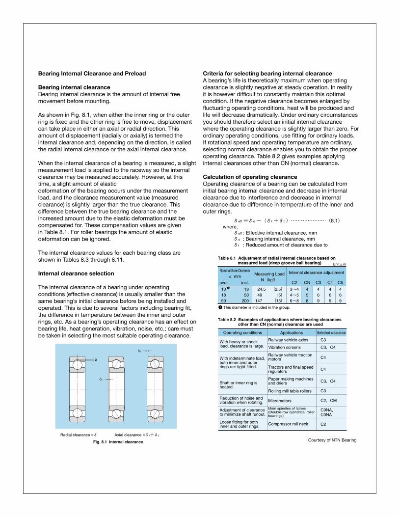
Bearing internal clearanceBearing internal clearance is the amount of internal free movement before mounting.
As shown in Fig. 8.1, when either the inner ring or the outer ring is fixed and the other ring is free to move, displacement can take place in either an axial or radial direction. This amount of displacement (radially or axially) is termed the internal clearance and, depending on the direction, is called the radial internal clearance or the axial internal clearance.
When the internal clearance of a bearing is measured, a slight measurement load is applied to the raceway so the internal clearance may be measured accurately. However, at this time, a slight amount of elasticdeformation of the bearing occurs under the measurement load, and the clearance measurement value (measured clearance) is slightly larger than the true clearance. This difference between the true bearing clearance and the increased amount due to the elastic deformation must be compensated for. These compensation values are given in Table 8.1. For roller bearings the amount of elastic deformation can be ignored.
The internal clearance values for each bearing class areshown in Tables 8.3 through 8.11.
Internal clearance selection
The internal clearance of a bearing under operating conditions (effective clearance) is usually smaller than the same bearing’s initial clearance before being installed and operated. This is due to several factors including bearing fit, the difference in temperature between the inner and outer rings, etc. As a bearing’s operating clearance has an effect on bearing life, heat generation, vibration, noise, etc.; care must be taken in selecting the most suitable operating clearance.
Criteria for selecting bearing internal clearance A bearing’s life is theoretically maximum when operating clearance is slightly negative at steady operation. In reality it is however difficult to constantly maintain this optimal condition. If the negative clearance becomes enlarged by fluctuating operating conditions, heat will be produced and life will decrease dramatically. Under ordinary circumstances you should therefore select an initial internal clearance where the operating clearance is slightly larger than zero. For ordinary operating conditions, use fitting for ordinary loads. If rotational speed and operating temperature are ordinary, selecting normal clearance enables you to obtain the proper operating clearance. Table 8.2 gives examples applying internal clearances other than CN (normal) clearance.
Calculation of operating clearanceOperating clearance of a bearing can be calculated from initial bearing internal clearance and decrease in internal clearance due to interference and decrease in internal clearance due to difference in temperature of the inner and outer rings.
●Bearing Internal Clearance and Preload
8.1 Bearing internal clearanceBearing internal clearance is the amount of internal free
movement before mounting.
As shown in Fig. 8.1, when either the inner ring or theouter ring is fixed and the other ring is free to move,displacement can take place in either an axial or radialdirection. This amount of displacement (radially or axially)is termed the internal clearance and, depending on thedirection, is called the radial internal clearance or theaxial internal clearance.
When the internal clearance of a bearing is measured, aslight measurement load is applied to the raceway so theinternal clearance may be measured accurately.However, at this time, a slight amount of elasticdeformation of the bearing occurs under the measurementload, and the clearance measurement value (measuredclearance) is slightly larger than the true clearance. Thisdifference between the true bearing clearance and theincreased amount due to the elastic deformation must becompensated for. These compensation values are given inTable 8.1. For roller bearings the amount of elasticdeformation can be ignored.
The internal clearance values for each bearing class areshown in Tables 8.3 through 8.11.
8.2 Internal clearance selectionThe internal clearance of a bearing under operating
conditions (effective clearance) is usually smaller than thesame bearing's initial clearance before being installed andoperated. This is due to several factors including bearingfit, the difference in temperature between the inner andouter rings, etc. As a bearing's operating clearance hasan effect on bearing life, heat generation, vibration, noise,etc.; care must be taken in selecting the most suitableoperating clearance.
A-58
δ2
δ1
δ
Fig. 8.1 Internal clearance
Radial clearance =δ Axial clearance =δ1+δ2
Nominal Bore Diameterd mm
over incl.
101850
1850
200
Measuring LoadN{kgf}
24.549
147
{2.5}{5}{15}
Internal clearance adjustment
C2 CN C3 C4 C5
3~44~56~8
458
469
469
469
Unitμm
1
Table 8.1 Adjustment of radial internal clearance based onmeasured load (deep groove ball bearing)
Table 8.2 Examples of applications where bearing clearancesother than CN (normal) clearance are used
Operating conditions Applications Selected clearance
Railway vehicle axles
Vibration screens
Tractors and final speedregulators
Rolling mill table rollers
Paper making machinesand driers
Railway vehicle tractionmotors
Main spindles of lathes (Double-row cylindrical rollerbearings)
Micromotors
C3
C3,C4With heavy or shockload, clearance is large.
Shaft or inner ring isheated.
Reduction of noise and vibration when rotating.
Adjustment of clearance to minimize shaft runout.
With indeterminate load,both inner and outerrings are tight-fitted.
C4
C4
C3
C2,CM
C9NA,C0NA
Compressor roll neckLoose fitting for both inner and outer rings. C2
C3,C4
8.2.1 Criteria for selecting bearing internal clearanceA bearing's life is theoretically maximum when
operating clearance is slightly negative at steadyoperation. In reality it is however difficult to constantlymaintain this optimal condition. If the negative clearancebecomes enlarged by fluctuating operating conditions,heat will be produced and life will decrease dramatically.Under ordinary circumstances you should thereforeselect an initial internal clearance where the operatingclearance is slightly larger than zero.
For ordinary operating conditions, use fitting forordinary loads. If rotational speed and operatingtemperature are ordinary, selecting normal clearanceenables you to obtain the proper operating clearance. Table 8.2 gives examples applying internal clearancesother than CN (normal) clearance.
8.2.2 Calculation of operating clearanceOperating clearance of a bearing can be calculated
from initial bearing internal clearance and decrease ininternal clearance due to interference and decrease ininternal clearance due to difference in temperature of theinner and outer rings.
δeff=δo-(δf+δt)…………………(8.1)where,
δeff : Effective internal clearance, mmδo : Bearing internal clearance, mmδf : Reduced amount of clearance due to
8. Bearing Internal Clearance and Preload
1 This diameter is included in the group.
Courtesy of NTN Bearing
Bearing Failure and AnalysisRolling bearings are precision machine elements found in a wide variety of applications. They are typically reliable even under the toughest conditions. Under normal operating conditions, bearings have a substantial service life, which is expressed as either a period of time or as the total number of rotations before the rolling elements or inner and outer ring fatigue or fail. Less than 1 percent (0.35 percent specifically—see Figure 1) of rolling bearings do not reach their expected life. (Source: FAG Bearing Antriebtechnik 18 from 1979.)Premature Bearing Failure
When a bearing does fail prematurely, it is usually due to causes that could have been avoided. For this reason, the possibility of reaching conclusions about the cause of a defect by means of studying its appearance is useful. It is most important to correct the causes and prevent future failures and the costs that follow. Most bearing failures such as flaking and pitting, spalling, unusual wear patterns, rust and corrosion, creeping, skewing and others are usually attributed to a relatively small group of causes that are often interrelated and correctable. These causes include lubrication, mounting, operational stress and bearing selection and environmental influence.
Proper/Improper Lubrication and “Grease Service Life”The purpose of lubricating the bearing is to cover the rolling and sliding contact surfaces with a thin oil film to avoid direct metal to metal contact. When done effectively it:1. Reduces friction and abrasion2. Transports heat generated by friction3. Prolongs service life4. Prevents rust and corrosion5. Excludes foreign objects and contamination from rolling elementsGrease is generally used for lubricating bearings because it is easy to handle and simplifies the sealing system, while oil lubrication is generally suitable for high speed or high temperature operations.Generally lubrication failures occur due to:1. The wrong lubricant type2. Too little grease/oil3. Too much grease/oil4. Mixing of grease/oil5. Contamination of the grease/oil by objects or water
In addition to considering normal bearing service life, normal grease service life is important to consider since together they maximize bearing life. Grease service life is the time during which proper bearing function is sustained by a particular quantity and category of grease. This is especially critical in pump, compressor, motor and super precision applications.Mounting and Installation of BearingsIt is critical in the mounting and installation process to pay strict attention to:1. Use of proper tools and ovens/induction heaters. Use a sleeve to impact the entire inner ring face of the ring that is being press fit.2. Verify the shaft and housing tolerances.If the fit is too tight, too much preload is created. If the fit is too loose, too little resulting preload may allow the shaft to rotate or creep in the bearing. Check for proper diameters, roundness and chamfer radius.3. Avoid misalignment or shaft deflection. This is especially critical in mounting bearings that have separable components such as cylindrical roller bearings where successful load bearing and optimal life are established or diminished at installation.4. Be aware of radial internal clearance (see Figure 2). It is critical to maintain the proper RIC established in the original design. The standard scale in order of ascending clearance is C2, C0, C3, C4, C5. The proper clearance for the application is critical in that it allows for the challenges of:
• Lubrication. A proper film of lubricant must be established between the rolling elements. Reducing internal clearance and impeding lubricant flow can lead to premature failure.• Shaft fit. A reduction in the radial internal clearance is inevitable when the bearing is press fit.• Heat. In normal bearing operation, heat is produced that creates thermal expansion of the inner and outer rings. This can reduce the internal clearance, which will reduce the optimal bearing life.
Bearing Failure and AnalysisBearing Failure and AnalysisRolling bearings are precision machine elements found in a wide variety of applications. They are typically reliable even under the toughest conditions. Under normal operating conditions, bearings have a substantial service life, which is expressed as either a period of time or as the total number of rotations before the rolling elements or inner and outer ring fatigue or fail. Less than 1 percent (0.35 percent specifically—see Figure 1) of rolling bearings do not reach their expected life. (Source: FAG Bearing Antriebtechnik 18 from 1979.)Premature Bearing Failure
When a bearing does fail prematurely, it is usually due to causes that could have been avoided. For this reason, the possibility of reaching conclusions about the cause of a defect by means of studying its appearance is useful. It is most important to correct the causes and prevent future failures and the costs that follow. Most bearing failures such as flaking and pitting, spalling, unusual wear patterns, rust and corrosion, creeping, skewing and others are usually attributed to a relatively small group of causes that are often interrelated and correctable. These causes include lubrication, mounting, operational stress and bearing selection and environmental influence.
Proper/Improper Lubrication and “Grease Service Life”The purpose of lubricating the bearing is to cover the rolling and sliding contact surfaces with a thin oil film to avoid direct metal to metal contact. When done effectively it:1. Reduces friction and abrasion2. Transports heat generated by friction3. Prolongs service life4. Prevents rust and corrosion5. Excludes foreign objects and contamination from rolling elementsGrease is generally used for lubricating bearings because it is easy to handle and simplifies the sealing system, while oil lubrication is generally suitable for high speed or high temperature operations.Generally lubrication failures occur due to:1. The wrong lubricant type2. Too little grease/oil3. Too much grease/oil4. Mixing of grease/oil5. Contamination of the grease/oil by objects or water
In addition to considering normal bearing service life, normal grease service life is important to consider since together they maximize bearing life. Grease service life is the time during which proper bearing function is sustained by a particular quantity and category of grease. This is especially critical in pump, compressor, motor and super precision applications.Mounting and Installation of BearingsIt is critical in the mounting and installation process to pay strict attention to:1. Use of proper tools and ovens/induction heaters. Use a sleeve to impact the entire inner ring face of the ring that is being press fit.2. Verify the shaft and housing tolerances.If the fit is too tight, too much preload is created. If the fit is too loose, too little resulting preload may allow the shaft to rotate or creep in the bearing. Check for proper diameters, roundness and chamfer radius.3. Avoid misalignment or shaft deflection. This is especially critical in mounting bearings that have separable components such as cylindrical roller bearings where successful load bearing and optimal life are established or diminished at installation.4. Be aware of radial internal clearance (see Figure 2). It is critical to maintain the proper RIC established in the original design. The standard scale in order of ascending clearance is C2, C0, C3, C4, C5. The proper clearance for the application is critical in that it allows for the challenges of:
• Lubrication. A proper film of lubricant must be established between the rolling elements. Reducing internal clearance and impeding lubricant flow can lead to premature failure.• Shaft fit. A reduction in the radial internal clearance is inevitable when the bearing is press fit.• Heat. In normal bearing operation, heat is produced that creates thermal expansion of the inner and outer rings. This can reduce the internal clearance, which will reduce the optimal bearing life.

Bearing Internal Clearance and Preload
Bearing internal clearanceBearing internal clearance is the amount of internal free movement before mounting.
As shown in Fig. 8.1, when either the inner ring or the outer ring is fixed and the other ring is free to move, displacement can take place in either an axial or radial direction. This amount of displacement (radially or axially) is termed the internal clearance and, depending on the direction, is called the radial internal clearance or the axial internal clearance.
When the internal clearance of a bearing is measured, a slight measurement load is applied to the raceway so the internal clearance may be measured accurately. However, at this time, a slight amount of elasticdeformation of the bearing occurs under the measurement load, and the clearance measurement value (measured clearance) is slightly larger than the true clearance. This difference between the true bearing clearance and the increased amount due to the elastic deformation must be compensated for. These compensation values are given in Table 8.1. For roller bearings the amount of elastic deformation can be ignored.
The internal clearance values for each bearing class areshown in Tables 8.3 through 8.11.
Internal clearance selection
The internal clearance of a bearing under operating conditions (effective clearance) is usually smaller than the same bearing’s initial clearance before being installed and operated. This is due to several factors including bearing fit, the difference in temperature between the inner and outer rings, etc. As a bearing’s operating clearance has an effect on bearing life, heat generation, vibration, noise, etc.; care must be taken in selecting the most suitable operating clearance.
Criteria for selecting bearing internal clearance A bearing’s life is theoretically maximum when operating clearance is slightly negative at steady operation. In reality it is however difficult to constantly maintain this optimal condition. If the negative clearance becomes enlarged by fluctuating operating conditions, heat will be produced and life will decrease dramatically. Under ordinary circumstances you should therefore select an initial internal clearance where the operating clearance is slightly larger than zero. For ordinary operating conditions, use fitting for ordinary loads. If rotational speed and operating temperature are ordinary, selecting normal clearance enables you to obtain the proper operating clearance. Table 8.2 gives examples applying internal clearances other than CN (normal) clearance.
Calculation of operating clearanceOperating clearance of a bearing can be calculated from initial bearing internal clearance and decrease in internal clearance due to interference and decrease in internal clearance due to difference in temperature of the inner and outer rings.
●Bearing Internal Clearance and Preload
8.1 Bearing internal clearanceBearing internal clearance is the amount of internal free
movement before mounting.
As shown in Fig. 8.1, when either the inner ring or theouter ring is fixed and the other ring is free to move,displacement can take place in either an axial or radialdirection. This amount of displacement (radially or axially)is termed the internal clearance and, depending on thedirection, is called the radial internal clearance or theaxial internal clearance.
When the internal clearance of a bearing is measured, aslight measurement load is applied to the raceway so theinternal clearance may be measured accurately.However, at this time, a slight amount of elasticdeformation of the bearing occurs under the measurementload, and the clearance measurement value (measuredclearance) is slightly larger than the true clearance. Thisdifference between the true bearing clearance and theincreased amount due to the elastic deformation must becompensated for. These compensation values are given inTable 8.1. For roller bearings the amount of elasticdeformation can be ignored.
The internal clearance values for each bearing class areshown in Tables 8.3 through 8.11.
8.2 Internal clearance selectionThe internal clearance of a bearing under operating
conditions (effective clearance) is usually smaller than thesame bearing's initial clearance before being installed andoperated. This is due to several factors including bearingfit, the difference in temperature between the inner andouter rings, etc. As a bearing's operating clearance hasan effect on bearing life, heat generation, vibration, noise,etc.; care must be taken in selecting the most suitableoperating clearance.
A-58
δ2
δ1
δ
Fig. 8.1 Internal clearance
Radial clearance =δ Axial clearance =δ1+δ2
Nominal Bore Diameterd mm
over incl.
101850
1850
200
Measuring LoadN{kgf}
24.549
147
{2.5}{5}{15}
Internal clearance adjustment
C2 CN C3 C4 C5
3~44~56~8
458
469
469
469
Unitμm
1
Table 8.1 Adjustment of radial internal clearance based onmeasured load (deep groove ball bearing)
Table 8.2 Examples of applications where bearing clearancesother than CN (normal) clearance are used
Operating conditions Applications Selected clearance
Railway vehicle axles
Vibration screens
Tractors and final speedregulators
Rolling mill table rollers
Paper making machinesand driers
Railway vehicle tractionmotors
Main spindles of lathes (Double-row cylindrical rollerbearings)
Micromotors
C3
C3,C4With heavy or shockload, clearance is large.
Shaft or inner ring isheated.
Reduction of noise and vibration when rotating.
Adjustment of clearance to minimize shaft runout.
With indeterminate load,both inner and outerrings are tight-fitted.
C4
C4
C3
C2,CM
C9NA,C0NA
Compressor roll neckLoose fitting for both inner and outer rings. C2
C3,C4
8.2.1 Criteria for selecting bearing internal clearanceA bearing's life is theoretically maximum when
operating clearance is slightly negative at steadyoperation. In reality it is however difficult to constantlymaintain this optimal condition. If the negative clearancebecomes enlarged by fluctuating operating conditions,heat will be produced and life will decrease dramatically.Under ordinary circumstances you should thereforeselect an initial internal clearance where the operatingclearance is slightly larger than zero.
For ordinary operating conditions, use fitting forordinary loads. If rotational speed and operatingtemperature are ordinary, selecting normal clearanceenables you to obtain the proper operating clearance. Table 8.2 gives examples applying internal clearancesother than CN (normal) clearance.
8.2.2 Calculation of operating clearanceOperating clearance of a bearing can be calculated
from initial bearing internal clearance and decrease ininternal clearance due to interference and decrease ininternal clearance due to difference in temperature of theinner and outer rings.
δeff=δo-(δf+δt)…………………(8.1)where,
δeff : Effective internal clearance, mmδo : Bearing internal clearance, mmδf : Reduced amount of clearance due to
8. Bearing Internal Clearance and Preload
1 This diameter is included in the group.
●Bearing Internal Clearance and Preload
8.1 Bearing internal clearanceBearing internal clearance is the amount of internal free
movement before mounting.
As shown in Fig. 8.1, when either the inner ring or theouter ring is fixed and the other ring is free to move,displacement can take place in either an axial or radialdirection. This amount of displacement (radially or axially)is termed the internal clearance and, depending on thedirection, is called the radial internal clearance or theaxial internal clearance.
When the internal clearance of a bearing is measured, aslight measurement load is applied to the raceway so theinternal clearance may be measured accurately.However, at this time, a slight amount of elasticdeformation of the bearing occurs under the measurementload, and the clearance measurement value (measuredclearance) is slightly larger than the true clearance. Thisdifference between the true bearing clearance and theincreased amount due to the elastic deformation must becompensated for. These compensation values are given inTable 8.1. For roller bearings the amount of elasticdeformation can be ignored.
The internal clearance values for each bearing class areshown in Tables 8.3 through 8.11.
8.2 Internal clearance selectionThe internal clearance of a bearing under operating
conditions (effective clearance) is usually smaller than thesame bearing's initial clearance before being installed andoperated. This is due to several factors including bearingfit, the difference in temperature between the inner andouter rings, etc. As a bearing's operating clearance hasan effect on bearing life, heat generation, vibration, noise,etc.; care must be taken in selecting the most suitableoperating clearance.
A-58
δ2
δ1
δ
Fig. 8.1 Internal clearance
Radial clearance =δ Axial clearance =δ1+δ2
Nominal Bore Diameterd mm
over incl.
101850
1850
200
Measuring LoadN{kgf}
24.549
147
{2.5}{5}{15}
Internal clearance adjustment
C2 CN C3 C4 C5
3~44~56~8
458
469
469
469
Unitμm
1
Table 8.1 Adjustment of radial internal clearance based onmeasured load (deep groove ball bearing)
Table 8.2 Examples of applications where bearing clearancesother than CN (normal) clearance are used
Operating conditions Applications Selected clearance
Railway vehicle axles
Vibration screens
Tractors and final speedregulators
Rolling mill table rollers
Paper making machinesand driers
Railway vehicle tractionmotors
Main spindles of lathes (Double-row cylindrical rollerbearings)
Micromotors
C3
C3,C4With heavy or shockload, clearance is large.
Shaft or inner ring isheated.
Reduction of noise and vibration when rotating.
Adjustment of clearance to minimize shaft runout.
With indeterminate load,both inner and outerrings are tight-fitted.
C4
C4
C3
C2,CM
C9NA,C0NA
Compressor roll neckLoose fitting for both inner and outer rings. C2
C3,C4
8.2.1 Criteria for selecting bearing internal clearanceA bearing's life is theoretically maximum when
operating clearance is slightly negative at steadyoperation. In reality it is however difficult to constantlymaintain this optimal condition. If the negative clearancebecomes enlarged by fluctuating operating conditions,heat will be produced and life will decrease dramatically.Under ordinary circumstances you should thereforeselect an initial internal clearance where the operatingclearance is slightly larger than zero.
For ordinary operating conditions, use fitting forordinary loads. If rotational speed and operatingtemperature are ordinary, selecting normal clearanceenables you to obtain the proper operating clearance. Table 8.2 gives examples applying internal clearancesother than CN (normal) clearance.
8.2.2 Calculation of operating clearanceOperating clearance of a bearing can be calculated
from initial bearing internal clearance and decrease ininternal clearance due to interference and decrease ininternal clearance due to difference in temperature of theinner and outer rings.
δeff=δo-(δf+δt)…………………(8.1)where,
δeff : Effective internal clearance, mmδo : Bearing internal clearance, mmδf : Reduced amount of clearance due to
8. Bearing Internal Clearance and Preload
1 This diameter is included in the group.
Courtesy of NTN Bearing
Bearing Failure and AnalysisRolling bearings are precision machine elements found in a wide variety of applications. They are typically reliable even under the toughest conditions. Under normal operating conditions, bearings have a substantial service life, which is expressed as either a period of time or as the total number of rotations before the rolling elements or inner and outer ring fatigue or fail. Less than 1 percent (0.35 percent specifically—see Figure 1) of rolling bearings do not reach their expected life. (Source: FAG Bearing Antriebtechnik 18 from 1979.)Premature Bearing Failure
When a bearing does fail prematurely, it is usually due to causes that could have been avoided. For this reason, the possibility of reaching conclusions about the cause of a defect by means of studying its appearance is useful. It is most important to correct the causes and prevent future failures and the costs that follow. Most bearing failures such as flaking and pitting, spalling, unusual wear patterns, rust and corrosion, creeping, skewing and others are usually attributed to a relatively small group of causes that are often interrelated and correctable. These causes include lubrication, mounting, operational stress and bearing selection and environmental influence.
Proper/Improper Lubrication and “Grease Service Life”The purpose of lubricating the bearing is to cover the rolling and sliding contact surfaces with a thin oil film to avoid direct metal to metal contact. When done effectively it:1. Reduces friction and abrasion2. Transports heat generated by friction3. Prolongs service life4. Prevents rust and corrosion5. Excludes foreign objects and contamination from rolling elementsGrease is generally used for lubricating bearings because it is easy to handle and simplifies the sealing system, while oil lubrication is generally suitable for high speed or high temperature operations.Generally lubrication failures occur due to:1. The wrong lubricant type2. Too little grease/oil3. Too much grease/oil4. Mixing of grease/oil5. Contamination of the grease/oil by objects or water
In addition to considering normal bearing service life, normal grease service life is important to consider since together they maximize bearing life. Grease service life is the time during which proper bearing function is sustained by a particular quantity and category of grease. This is especially critical in pump, compressor, motor and super precision applications.Mounting and Installation of BearingsIt is critical in the mounting and installation process to pay strict attention to:1. Use of proper tools and ovens/induction heaters. Use a sleeve to impact the entire inner ring face of the ring that is being press fit.2. Verify the shaft and housing tolerances.If the fit is too tight, too much preload is created. If the fit is too loose, too little resulting preload may allow the shaft to rotate or creep in the bearing. Check for proper diameters, roundness and chamfer radius.3. Avoid misalignment or shaft deflection. This is especially critical in mounting bearings that have separable components such as cylindrical roller bearings where successful load bearing and optimal life are established or diminished at installation.4. Be aware of radial internal clearance (see Figure 2). It is critical to maintain the proper RIC established in the original design. The standard scale in order of ascending clearance is C2, C0, C3, C4, C5. The proper clearance for the application is critical in that it allows for the challenges of:
• Lubrication. A proper film of lubricant must be established between the rolling elements. Reducing internal clearance and impeding lubricant flow can lead to premature failure.• Shaft fit. A reduction in the radial internal clearance is inevitable when the bearing is press fit.• Heat. In normal bearing operation, heat is produced that creates thermal expansion of the inner and outer rings. This can reduce the internal clearance, which will reduce the optimal bearing life.
Bearing Failure and AnalysisBearing Failure and AnalysisRolling bearings are precision machine elements found in a wide variety of applications. They are typically reliable even under the toughest conditions. Under normal operating conditions, bearings have a substantial service life, which is expressed as either a period of time or as the total number of rotations before the rolling elements or inner and outer ring fatigue or fail. Less than 1 percent (0.35 percent specifically—see Figure 1) of rolling bearings do not reach their expected life. (Source: FAG Bearing Antriebtechnik 18 from 1979.)Premature Bearing Failure
When a bearing does fail prematurely, it is usually due to causes that could have been avoided. For this reason, the possibility of reaching conclusions about the cause of a defect by means of studying its appearance is useful. It is most important to correct the causes and prevent future failures and the costs that follow. Most bearing failures such as flaking and pitting, spalling, unusual wear patterns, rust and corrosion, creeping, skewing and others are usually attributed to a relatively small group of causes that are often interrelated and correctable. These causes include lubrication, mounting, operational stress and bearing selection and environmental influence.
Proper/Improper Lubrication and “Grease Service Life”The purpose of lubricating the bearing is to cover the rolling and sliding contact surfaces with a thin oil film to avoid direct metal to metal contact. When done effectively it:1. Reduces friction and abrasion2. Transports heat generated by friction3. Prolongs service life4. Prevents rust and corrosion5. Excludes foreign objects and contamination from rolling elementsGrease is generally used for lubricating bearings because it is easy to handle and simplifies the sealing system, while oil lubrication is generally suitable for high speed or high temperature operations.Generally lubrication failures occur due to:1. The wrong lubricant type2. Too little grease/oil3. Too much grease/oil4. Mixing of grease/oil5. Contamination of the grease/oil by objects or water
In addition to considering normal bearing service life, normal grease service life is important to consider since together they maximize bearing life. Grease service life is the time during which proper bearing function is sustained by a particular quantity and category of grease. This is especially critical in pump, compressor, motor and super precision applications.Mounting and Installation of BearingsIt is critical in the mounting and installation process to pay strict attention to:1. Use of proper tools and ovens/induction heaters. Use a sleeve to impact the entire inner ring face of the ring that is being press fit.2. Verify the shaft and housing tolerances.If the fit is too tight, too much preload is created. If the fit is too loose, too little resulting preload may allow the shaft to rotate or creep in the bearing. Check for proper diameters, roundness and chamfer radius.3. Avoid misalignment or shaft deflection. This is especially critical in mounting bearings that have separable components such as cylindrical roller bearings where successful load bearing and optimal life are established or diminished at installation.4. Be aware of radial internal clearance (see Figure 2). It is critical to maintain the proper RIC established in the original design. The standard scale in order of ascending clearance is C2, C0, C3, C4, C5. The proper clearance for the application is critical in that it allows for the challenges of:
• Lubrication. A proper film of lubricant must be established between the rolling elements. Reducing internal clearance and impeding lubricant flow can lead to premature failure.• Shaft fit. A reduction in the radial internal clearance is inevitable when the bearing is press fit.• Heat. In normal bearing operation, heat is produced that creates thermal expansion of the inner and outer rings. This can reduce the internal clearance, which will reduce the optimal bearing life.

Needle roller bearingsNeedle roller bearings use needle rollers as rolling elements. The needle rollers are a maximum of 5 mm in diameter and are 3 to 10 times as long as they are in diameter. Because the bearings use needle rollers as rolling elements, the cross-section is thin, but they have a high load capacity for their size. Because of the large number of rolling elements, the bearings have high rigidity and are ideally suited to wobbling or pivoting motion.
There is a profusion of types of needle roller bearings, and just a few of the most representative types are covered here. For details, see the catalog devoted to the concerned type of bearing.
Bearing unitA unit comprised of a ball bearing inserted into various types of housings. The housing can be bolted onto machinery and the inner ring can be easily mounted on the shaft with a set screw. This means the bearing unit can support rotating equipment without special design to allow for mounting. A variety of standardized housing shapes is available, including pillow and flange types. The outer diameter of the bearing is spherical just like the inner diameter of the housing, so it capable of aligning itself on the shaft. For lubrication, grease is sealed inside the bearing, and particle generation is prevented by a double seal. For details, see the catalog devoted to the concerned type of bearing.
A-11
●Classification and Characteristics of Rolling Bearings
Table 1.9 Main types of needle roller bearings
Needle roller bearings Bearing unit
Needle roller bearings use needle rollers as rollingelements. The needle rollers are a maximum of 5 mm indiameter and are 3 to 10 times as long as they are indiameter. Because the bearings use needle rollers asrolling elements, the cross-section is thin, but they have ahigh load capacity for their size. Because of the largenumber of rolling elements, the bearings have high rigidityand are ideally suited to wobbling or pivoting motion.
There is a profusion of types of needle roller bearings,and just a few of the most representative types arecovered here. For details, see the catalog devoted to theconcerned type of bearing.
A unit comprised of a ball bearing inserted into varioustypes of housings. The housing can be bolted ontomachinery and the inner ring can be easily mounted onthe shaft with a set screw.
This means the bearing unit can support rotatingequipment without special design to allow for mounting. Avariety of standardized housing shapes is available,including pillow and flange types. The outer diameter ofthe bearing is spherical just like the inner diameter of thehousing, so it capable of aligning itself on the shaft.
For lubrication, grease is sealed inside the bearing, andparticle generation is prevented by a double seal. Fordetails, see the catalog devoted to the concerned type ofbearing.
Type Needle roller bearing with cage
Solid type needle roller bearings
Shell type needle roller bearings
Roller follower Cam follower
Co
nfi
gu
rati
on
Grease fitting
Housing
Spherical outer ring
Slinger
Special rubber seal
Setscrew with ball
Ball
Fig. 1.4 Oil-lubricated bearing unit
A-11
●Classification and Characteristics of Rolling Bearings
Table 1.9 Main types of needle roller bearings
Needle roller bearings Bearing unit
Needle roller bearings use needle rollers as rollingelements. The needle rollers are a maximum of 5 mm indiameter and are 3 to 10 times as long as they are indiameter. Because the bearings use needle rollers asrolling elements, the cross-section is thin, but they have ahigh load capacity for their size. Because of the largenumber of rolling elements, the bearings have high rigidityand are ideally suited to wobbling or pivoting motion.
There is a profusion of types of needle roller bearings,and just a few of the most representative types arecovered here. For details, see the catalog devoted to theconcerned type of bearing.
A unit comprised of a ball bearing inserted into varioustypes of housings. The housing can be bolted ontomachinery and the inner ring can be easily mounted onthe shaft with a set screw.
This means the bearing unit can support rotatingequipment without special design to allow for mounting. Avariety of standardized housing shapes is available,including pillow and flange types. The outer diameter ofthe bearing is spherical just like the inner diameter of thehousing, so it capable of aligning itself on the shaft.
For lubrication, grease is sealed inside the bearing, andparticle generation is prevented by a double seal. Fordetails, see the catalog devoted to the concerned type ofbearing.
Type Needle roller bearing with cage
Solid type needle roller bearings
Shell type needle roller bearings
Roller follower Cam follower
Co
nfi
gu
rati
on
Grease fitting
Housing
Spherical outer ring
Slinger
Special rubber seal
Setscrew with ball
Ball
Fig. 1.4 Oil-lubricated bearing unit
Operational Stress and Bearing SelectionIt is generally the exception to find a bearing that has been improperly designed into an application. However, factors within the larger application may change. If loads become too high, overloading and early fatigue may follow. If they are too low, skidding and improper loading of the rolling elements occur. Early failure will follow in each situation. Similar issues arise with improper internal clearance. The first sign of these issues will be unusual noises and/or increased temperatures.• Increased temperature. Bearing temperature generally rises with start-up and stabilizes at a temperature slightly lower than at start-up (normally 10 to 40 deg C higher than room temperature). A desirable bearing temperature is below 100 deg C.• Noises. Abnormal bearing sounds typically indicate certain issues in the bearing application. While this is a subjective test, it is helpful to know that a screech or howl sound generally indicates too large an internal clearance or poor lubrication on a cylindrical roller bearing while a crunching felt when the shaft is rotated by hand usually indicates contamination of the raceways. See www.pump-zone.com for a table of abnormal bearing sounds.Operational stresses in the applications can impact bearing life as well. It is critical to isolate vibrations in associated equipment as they can cause uneven running and unusual noises.
Environmental InfluenceEven with the best design, lubrication and installation failures will occur if the operating environment is not considered. While many potential issues exist, the primary ones are:1. Dust and dirt that can aggressively contaminate a bearing. Great care should be given to use proper sealingtechniques.2. Aggressive media or water. Once again, sealing is primary. The use of specialty type seals is recommended such as pump mechanical or labyrinth style seals that do not scorethe shaft.3. External heat. The ambient operating temperature mandates many choices in radial internal clearance, high temperature lubricants, intermittent or continuous running and others that affect bearing life.4. Current passage or electrolytic corrosion. If current is allowed to flow through the rolling elements, sparks can create pitting or fluting on the bearing surfaces. This should be corrected by creating a bypass circuit for the current or through the use of insulation on or within the bearing. This should be an inherent design consideration in applications such as wind turbines and all power generating equipment.
In conclusion, the first step in the overall prevention of bearing failure lies in the consideration of bearing technologies most suitable to the application with regard to specifications, recommendations, maintenance strategies, fatigue life and wear resistance of the bearing in relation to the application. That being said, premature bearing failure within a proper application is typically attributed to one or more of the causes discussed (lubrication, mounting, operational stress and bearing selection or environmental influence) and can and should be corrected to avoid future bearing failures and additional cost.
P&SSources• Barden Corporation. Machine Tool Technical Bulletin for Engineering and Lubrication. 2010.• FAG Bearings Corp. Rolling Bearing Damage. Publ. No. WL 82 102/2 December 1997.• Fersa Bearings. Roller Bearings: Failure Diagnosis. 2009.• Koyo Bearing Corp. Rolling Bearings: Failures, Causes and Countermeasures. Catalog No. 322E. December 1995.• NTN Bearing Corp. Products and Technology. Care and Maintenance of Bearings. 2009.Figure 2. Radial internal clearance.
Courtesy of NTN Bearing

Tapered roller bearingsTapered roller bearings are designed so the inner/outer ring raceway and apex of the tapered rollers intersect at one point on the bearing centerline. By receiving combined load from inner and outer ring, the rollers are pushed against the inner ring rib and roll guided with rib. Induced force is produced in the axial direction when a radial load is applied, so must be handled by using a pair of bearings. The inner ring with rollers and outer ring come apart, thus facilitating mounting with clearance or preload. Assembled clearance is however hard to manage and requires special attention. Tapered roller bearings are capable of supporting large loads in both the axial and radial directions. NTN bearings with 4T-, ET-, T- and U attached to the name conform to ISO and JIS standards for sub-unit dimensions (nominal contact angle, nominal small end diameter of outer ring) and are internationally interchangeable. NTN also has a line of case hardened steel bearingsdesigned for longer life (ETA-, ET-, etc.). NTN tapered roller bearings also include bearings with two and four rows of tapered rollers for extra-heavy loads.
Spherical roller bearingsEquipped with an outer ring with a spherical raceway surface and an inner ring which holds two rows of barrelshaped rolling elements, NTN spherical roller bearings are able to adjust center alignment to handle inclination of the axle or shaft. There are variety of bearing types that differ according to internal design. Spherical roller bearings include as type equipped withan inner ring with a tapered bore. The bearing can easily be mounted on a shaft by means of an adapter or withdrawal sleeve. The bearing is capable of supporting heavy loads, and is therefore often used in industrial machinery. When heavy axial load is applied to the bearing, the load on rollers of another row is disappeared, and can cause problems. Attention must therefore be paid to operating conditions.
Thrust bearingsThere are many types of thrust bearings that differ according to shape of rolling element and application. Allowable rotational speed is generally low and special attention must be paid to lubrication. In addition to the ones given below, there are various types of thrust bearings for special applications. For details, see the catalog devoted to the concerned type of bearing.
A-10
●Classification and Characteristics of Rolling Bearings
Tapered roller bearings
Tapered roller bearings are designed so the inner/outerring raceway and apex of the tapered rollers intersect atone point on the bearing centerline. By receivingcombined load from inner and outer ring, the rollers arepushed against the inner ring rib and roll guided with rib.
Induced force is produced in the axial direction when aradial load is applied, so must be handled by using a pairof bearings. The inner ring with rollers and outer ringcome apart, thus facilitating mounting with clearance orpreload. Assembled clearance is however hard tomanage and requires special attention. Tapered rollerbearings are capable of supporting large loads in both theaxial and radial directions.
NTN bearings with 4T-, ET-, T- and U attached to thename conform to ISO and JIS standards for sub-unitdimensions (nominal contact angle, nominal small enddiameter of outer ring) and are internationallyinterchangeable.
NTN also has a line of case hardened steel bearingsdesigned for longer life (ETA-, ET-, etc.). NTN taperedroller bearings also include bearings with two and fourrows of tapered rollers for extra-heavy loads.
Fig. 1.3 Tapered roller bearings
E2α
Sub-unit dimensions
E : nominal small end diameter of outer ringα : Nominal contact angle
Table 1.7 Types of spherical roller bearings
Table 1.8 Types of thrust bearings
Spherical roller bearings
Equipped with an outer ring with a spherical racewaysurface and an inner ring which holds two rows of barrel-shaped rolling elements, NTN spherical roller bearingsare able to adjust center alignment to handle inclination ofthe axle or shaft.
There are variety of bearing types that differ accordingto internal design.
Spherical roller bearings include as type equipped withan inner ring with a tapered bore. The bearing can easilybe mounted on a shaft by means of an adapter orwithdrawal sleeve. The bearing is capable of supportingheavy loads, and is therefore often used in industrialmachinery. When heavy axial load is applied to thebearing, the load on rollers of another row is disappeared,and can cause problems. Attention must therefore bepaid to operating conditions.
Thrust bearings
TypeStandard(B type) C type E type213 type
Co
nfi
gu
rati
on
GS/WS type raceway washer
AS type raceway washer
AXK type
Center alignment angle
Type Single direction thrust ballbearing Needle roller thrust bearing
Cylindrical roller thrust bearing Spherical roller thrust bearing
Co
nfi
gu
rati
on
There are many types of thrust bearings that differaccording to shape of rolling element and application.Allowable rotational speed is generally low and specialattention must be paid to lubrication.
In addition to the ones given below, there are varioustypes of thrust bearings for special applications. For details,see the catalog devoted to the concerned type of bearing.
A-10
●Classification and Characteristics of Rolling Bearings
Tapered roller bearings
Tapered roller bearings are designed so the inner/outerring raceway and apex of the tapered rollers intersect atone point on the bearing centerline. By receivingcombined load from inner and outer ring, the rollers arepushed against the inner ring rib and roll guided with rib.
Induced force is produced in the axial direction when aradial load is applied, so must be handled by using a pairof bearings. The inner ring with rollers and outer ringcome apart, thus facilitating mounting with clearance orpreload. Assembled clearance is however hard tomanage and requires special attention. Tapered rollerbearings are capable of supporting large loads in both theaxial and radial directions.
NTN bearings with 4T-, ET-, T- and U attached to thename conform to ISO and JIS standards for sub-unitdimensions (nominal contact angle, nominal small enddiameter of outer ring) and are internationallyinterchangeable.
NTN also has a line of case hardened steel bearingsdesigned for longer life (ETA-, ET-, etc.). NTN taperedroller bearings also include bearings with two and fourrows of tapered rollers for extra-heavy loads.
Fig. 1.3 Tapered roller bearings
E2α
Sub-unit dimensions
E : nominal small end diameter of outer ringα : Nominal contact angle
Table 1.7 Types of spherical roller bearings
Table 1.8 Types of thrust bearings
Spherical roller bearings
Equipped with an outer ring with a spherical racewaysurface and an inner ring which holds two rows of barrel-shaped rolling elements, NTN spherical roller bearingsare able to adjust center alignment to handle inclination ofthe axle or shaft.
There are variety of bearing types that differ accordingto internal design.
Spherical roller bearings include as type equipped withan inner ring with a tapered bore. The bearing can easilybe mounted on a shaft by means of an adapter orwithdrawal sleeve. The bearing is capable of supportingheavy loads, and is therefore often used in industrialmachinery. When heavy axial load is applied to thebearing, the load on rollers of another row is disappeared,and can cause problems. Attention must therefore bepaid to operating conditions.
Thrust bearings
TypeStandard(B type) C type E type213 type
Co
nfi
gu
rati
on
GS/WS type raceway washer
AS type raceway washer
AXK type
Center alignment angle
Type Single direction thrust ballbearing Needle roller thrust bearing
Cylindrical roller thrust bearing Spherical roller thrust bearing
Co
nfi
gu
rati
on
There are many types of thrust bearings that differaccording to shape of rolling element and application.Allowable rotational speed is generally low and specialattention must be paid to lubrication.
In addition to the ones given below, there are varioustypes of thrust bearings for special applications. For details,see the catalog devoted to the concerned type of bearing.
A-10
●Classification and Characteristics of Rolling Bearings
Tapered roller bearings
Tapered roller bearings are designed so the inner/outerring raceway and apex of the tapered rollers intersect atone point on the bearing centerline. By receivingcombined load from inner and outer ring, the rollers arepushed against the inner ring rib and roll guided with rib.
Induced force is produced in the axial direction when aradial load is applied, so must be handled by using a pairof bearings. The inner ring with rollers and outer ringcome apart, thus facilitating mounting with clearance orpreload. Assembled clearance is however hard tomanage and requires special attention. Tapered rollerbearings are capable of supporting large loads in both theaxial and radial directions.
NTN bearings with 4T-, ET-, T- and U attached to thename conform to ISO and JIS standards for sub-unitdimensions (nominal contact angle, nominal small enddiameter of outer ring) and are internationallyinterchangeable.
NTN also has a line of case hardened steel bearingsdesigned for longer life (ETA-, ET-, etc.). NTN taperedroller bearings also include bearings with two and fourrows of tapered rollers for extra-heavy loads.
Fig. 1.3 Tapered roller bearings
E2α
Sub-unit dimensions
E : nominal small end diameter of outer ringα : Nominal contact angle
Table 1.7 Types of spherical roller bearings
Table 1.8 Types of thrust bearings
Spherical roller bearings
Equipped with an outer ring with a spherical racewaysurface and an inner ring which holds two rows of barrel-shaped rolling elements, NTN spherical roller bearingsare able to adjust center alignment to handle inclination ofthe axle or shaft.
There are variety of bearing types that differ accordingto internal design.
Spherical roller bearings include as type equipped withan inner ring with a tapered bore. The bearing can easilybe mounted on a shaft by means of an adapter orwithdrawal sleeve. The bearing is capable of supportingheavy loads, and is therefore often used in industrialmachinery. When heavy axial load is applied to thebearing, the load on rollers of another row is disappeared,and can cause problems. Attention must therefore bepaid to operating conditions.
Thrust bearings
TypeStandard(B type) C type E type213 type
Co
nfi
gu
rati
on
GS/WS type raceway washer
AS type raceway washer
AXK type
Center alignment angle
Type Single direction thrust ballbearing Needle roller thrust bearing
Cylindrical roller thrust bearing Spherical roller thrust bearing
Co
nfi
gu
rati
on
There are many types of thrust bearings that differaccording to shape of rolling element and application.Allowable rotational speed is generally low and specialattention must be paid to lubrication.
In addition to the ones given below, there are varioustypes of thrust bearings for special applications. For details,see the catalog devoted to the concerned type of bearing.
Bearing Damage and Corrective Measures
If handled correctly, bearings can generally be used for a long time before reaching their fatigue life. If damage occurs prematurely, the problem could stem from improper bearing selection, handling or lubrication. In this occurs, take note of the type of machine on which the bearings is used, the place where it is mounted, service conditions and surrounding structure. By investigating several possible causes surmised from the type of damage and condition at the time the damage occurred, it is possible to prevent the same kind of damage from reoccurring. Table 16.1 gives the main causes of bearing damage and remedies for correcting the problem.
If handled correctly, bearings can generally be used fora long time before reaching their fatigue life. If damageoccurs prematurely, the problem could stem fromimproper bearing selection, handling or lubrication. In thisoccurs, take note of the type of machine on which thebearings is used, the place where it is mounted, service
conditions and surrounding structure. By investigatingseveral possible causes surmised from the type ofdamage and condition at the time the damage occurred, itis possible to prevent the same kind of damage fromreoccurring. Table 16.1 gives the main causes of bearingdamage and remedies for correcting the problem.
16. Bearing Damage and Corrective Measures
●Bearing Damage and Corrective Measures
A-96
Flaking Surface of the raceway and rolling elements peels away in flakesConspicuous hills and valleys form soon afterward. C
auses
Co
rrection
Seizure The bearing heats up and becomes discolored.Eventually the bearing will seize up. C
auses
Co
rrection
Cracking andnotching
Localized flaking occurs.Little cracks or notches appear. C
auses
Co
rrection
Description
¡Excessive load, fatigue life, improper handling
¡Improper mounting.¡Improper precision in the shaft or housing.¡Insufficient clearance.¡Contamination.¡Rust.¡Improper lubrication¡Drop in hardness due to abnormally
high temperatures.
¡Select a different type of bearing.¡Reevaluate the clearance.¡Improve the precision of the shaft and
housing.¡Review application conditions.¡Improve assembly method and
handling.¡Reevaluate the layout (design) of the area around the bearing.¡Review lubricant type and lubrication methods.
¡Insufficient clearance (including clearances made smaller by local deformation).
¡Insufficient lubrication or improper lubricant.
¡Excessive loads (excessive preload).¡Skewed rollers.¡Reduction in hardness due to
abnormal temperature rise
¡Riview lubricant type and quantity.¡Check for proper clearance. (Increase clearances.)¡Take steps to prevent misalignment.¡Review application conditions.¡Improve assembly method and
handling.
¡Excessive shock loads.¡Improper handling (use of steel hammer,
cutting by large particles of foreign matter)¡Formation of decomposed surface
layer due to improper lubrication¡Excessive interference.¡Large flaking.¡Friction cracking.¡Imprecision of mounting mate
(oversized fillet radius)
¡Review lubricant (friction crack prevention).
¡Select proper interference and review materials.
¡Review service conditions.¡Improve assembly procedures and
take more care in handling.
Table 16.1 Bearing damage, main causes of bearing damage and remedies for correcting the problem
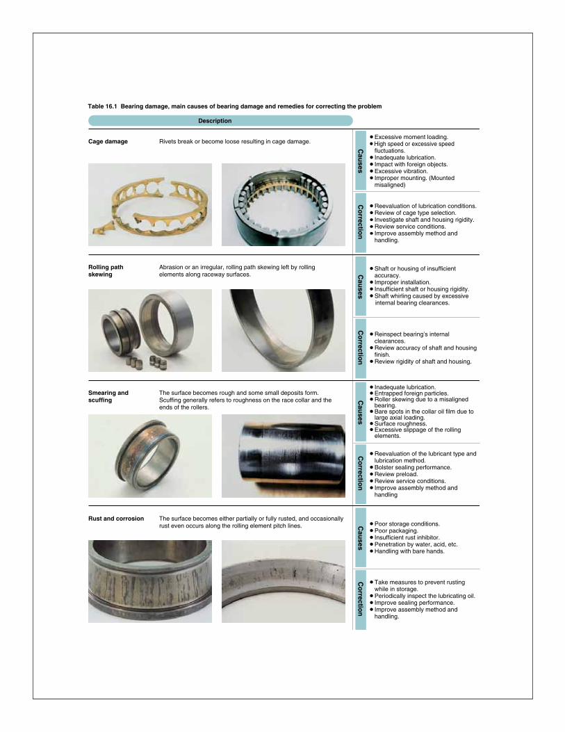
Angular contact ball bearingsThe line that unites point of contact of the inner ring, ball and outer ring runs at a certain angle (contact angle) in the radial direction. Bearings are generally designed with three contact angles. Angular contact ball bearings can support an axial load,but cannot be used by single bearing because of the contact angle. They must instead be used in pairs or in combinations.Angular contact ball bearings include double row angular contact ball bearings for which the inner and outer rings are combined as a single unit. The contact angle of double row angular contact ball bearings is 25°. There are also four-point contact bearings that can support an axial load in both directions by themselves. These bearings however require caution because problems such as excessive temperature rise and wearing could occur depending on the load conditions.
Cylindrical roller bearingsUses rollers for rolling elements, and therefore has a high load capacity. The rollers are guided by the ribs of the inner or outer ring. The inner and outer rings can be separated to facilitate assembly, and both can be fit with shaft or housing tightly. If there is no ribs, either the inner or the outer ring can move freely in the axial direction. Cylindrical roller bearings are therefore ideal to be used as so-called “free side bearings” that absorb shaft expansion. In the case where there is a ribs, the bearing can bear a slight axial load between the end of the rollers and the ribs. Cylindrical roller bearings include the HT type which modifies the shape of roller end face and ribs for increasing axial road capacity. And the E type with a special internal design for enhancing radial load capacity. The E type is standardized for small-diameter sizes. Table 1.6 shows the basic configuration for cylindrical roller bearings.
In addition to these, there are cylindrical roller bearings with multiple rows of rollers and the SL type of full complement roller bearing without cage.
●Classification and Characteristics of Rolling Bearings
A-9
Angular contact ball bearings
The line that unites point of contact of the inner ring,ball and outer ring runs at a certain angle (contact angle)in the radial direction. Bearings are generally designedwith three contact angles.
Angular contact ball bearings can support an axial load,but cannot be used by single bearing because of thecontact angle. They must instead be used in pairs or incombinations.
Angular contact ball bearings include double rowangular contact ball bearings for which the inner andouter rings are combined as a single unit. The contactangle of double row angular contact ball bearings is 25˚.
There are also four-point contact bearings that cansupport an axial load in both directions by themselves.These bearings however require caution becauseproblems such as excessive temperature rise andwearing could occur depending on the load conditions.
Table 1.6 Types of cylindrical roller bearings
Cylindrical roller bearings
Uses rollers for rolling elements, and therefore has ahigh load capacity. The rollers are guided by the ribs ofthe inner or outer ring. The inner and outer rings can beseparated to facilitate assembly, and both can be fit withshaft or housing tightly. If there is no ribs, either the inneror the outer ring can move freely in the axial direction.Cylindrical roller bearings are therefore ideal to be usedas so-called "free side bearings" that absorb shaftexpansion. In the case where there is a ribs, the bearingcan bear a slight axial load between the end of the rollersand the ribs. Cylindrical roller bearings include the HTtype which modifies the shape of roller end face and ribsfor increasing axial road capacity. And the E type with aspecial internal design for enhancing radial load capacity.The E type is standardized for small-diameter sizes.Table 1.6 shows the basic configuration for cylindricalroller bearings.
In addition to these, there are cylindrical roller bearingswith multiple rows of rollers and the SL type of fullcomplement roller bearing without cage.
NUP type
NF type
NJ type
N type
NU type
NH type
NU typeN type
NUP typeNH type (NJ+HJ)
NJ typeNF type
Typeand
Symbol
Dra
win
gs
Table 1.4 Configuration of double row angular contact ball bearings
Table 1.5 Combinations of duplex angular contact ball bearings
Table 1.3 Contact angle and symbol
Contact angle
Contact angle
Contact anglesymbol
15°
C
30°
A
40°
B
Contact angle and contact angle symbol
1)
Note 1: Contact angle symbol has been abbreviated as "A".
Open ShieldZZ
Contactsealed
LLD
Non-contactsealedLLM
Typeand
symbol
Co
nfi
gu
rati
on
r r
Back-to-backduplex
DB
Tandem duplexDT
Face-to-faceduplex
DF
Typeand
symbol
Co
nfi
gu
rati
on
●Classification and Characteristics of Rolling Bearings
A-9
Angular contact ball bearings
The line that unites point of contact of the inner ring,ball and outer ring runs at a certain angle (contact angle)in the radial direction. Bearings are generally designedwith three contact angles.
Angular contact ball bearings can support an axial load,but cannot be used by single bearing because of thecontact angle. They must instead be used in pairs or incombinations.
Angular contact ball bearings include double rowangular contact ball bearings for which the inner andouter rings are combined as a single unit. The contactangle of double row angular contact ball bearings is 25˚.
There are also four-point contact bearings that cansupport an axial load in both directions by themselves.These bearings however require caution becauseproblems such as excessive temperature rise andwearing could occur depending on the load conditions.
Table 1.6 Types of cylindrical roller bearings
Cylindrical roller bearings
Uses rollers for rolling elements, and therefore has ahigh load capacity. The rollers are guided by the ribs ofthe inner or outer ring. The inner and outer rings can beseparated to facilitate assembly, and both can be fit withshaft or housing tightly. If there is no ribs, either the inneror the outer ring can move freely in the axial direction.Cylindrical roller bearings are therefore ideal to be usedas so-called "free side bearings" that absorb shaftexpansion. In the case where there is a ribs, the bearingcan bear a slight axial load between the end of the rollersand the ribs. Cylindrical roller bearings include the HTtype which modifies the shape of roller end face and ribsfor increasing axial road capacity. And the E type with aspecial internal design for enhancing radial load capacity.The E type is standardized for small-diameter sizes.Table 1.6 shows the basic configuration for cylindricalroller bearings.
In addition to these, there are cylindrical roller bearingswith multiple rows of rollers and the SL type of fullcomplement roller bearing without cage.
NUP type
NF type
NJ type
N type
NU type
NH type
NU typeN type
NUP typeNH type (NJ+HJ)
NJ typeNF type
Typeand
Symbol
Dra
win
gs
Table 1.4 Configuration of double row angular contact ball bearings
Table 1.5 Combinations of duplex angular contact ball bearings
Table 1.3 Contact angle and symbol
Contact angle
Contact angle
Contact anglesymbol
15°
C
30°
A
40°
B
Contact angle and contact angle symbol
1)
Note 1: Contact angle symbol has been abbreviated as "A".
Open ShieldZZ
Contactsealed
LLD
Non-contactsealedLLM
Typeand
symbol
Co
nfi
gu
rati
on
r r
Back-to-backduplex
DB
Tandem duplexDT
Face-to-faceduplex
DF
Typeand
symbol
Co
nfi
gu
rati
on
A-97
●Bearing Damage and Corrective Measures
Cage damage Rivets break or become loose resulting in cage damage.
Cau
sesC
orrectio
n
Rolling path skewing
Abrasion or an irregular, rolling path skewing left by rolling elements along raceway surfaces. C
auses
Co
rrection
Smearing andscuffing
The surface becomes rough and some small deposits form.Scuffing generally refers to roughness on the race collar and theends of the rollers.
Cau
sesC
orrectio
n
Rust and corrosion The surface becomes either partially or fully rusted, and occasionallyrust even occurs along the rolling element pitch lines. C
auses
Co
rrection
Description
¡Excessive moment loading.¡High speed or excessive speed
fluctuations.¡Inadequate lubrication.¡Impact with foreign objects.¡Excessive vibration.¡Improper mounting. (Mounted
misaligned)
¡Reevaluation of lubrication conditions.¡Review of cage type selection.¡Investigate shaft and housing rigidity.¡Review service conditions.¡Improve assembly method and
handling.
¡Shaft or housing of insufficient accuracy.
¡Improper installation.¡Insufficient shaft or housing rigidity.¡Shaft whirling caused by excessive internal bearing clearances.
¡Reinspect bearing’s internal clearances.
¡Review accuracy of shaft and housing finish.
¡Review rigidity of shaft and housing.
¡Inadequate lubrication.¡Entrapped foreign particles.¡Roller skewing due to a misaligned
bearing.¡Bare spots in the collar oil film due to
large axial loading.¡Surface roughness.¡Excessive slippage of the rolling
elements.
¡Reevaluation of the lubricant type and lubrication method.
¡Bolster sealing performance.¡Review preload.¡Review service conditions.¡Improve assembly method and
handling
¡Poor storage conditions.¡Poor packaging.¡Insufficient rust inhibitor.¡Penetration by water, acid, etc.¡Handling with bare hands.
¡Take measures to prevent rusting while in storage.
¡Periodically inspect the lubricating oil.¡Improve sealing performance.¡Improve assembly method and
handling.
Table 16.1 Bearing damage, main causes of bearing damage and remedies for correcting the problem

1.3 Characteristics of rolling bearings1.3.1 Characteristics of rolling bearingsRolling bearings come in many shapes and varieties, each with its own distinctive features. However, when compared with sliding bearings, rolling bearings all have the following advantages:(1) The starting friction coefficient is lower and there is little difference between this and the dynamic friction coefficient.(2) They are internationally standardized, interchangeable and readily obtainable.(3) They are easy to lubricate and consume less lubricant.(4) As a general rule, one bearing can carry both radial and axial loads at the same time.(5) May be used in either high or low temperature applications.(6) Bearing rigidity can be improved by preloading.
Construction, classes, and special features of rolling bearings are fully described in the boundary dimensions and bearing numbering system section.
1.3.2 Ball bearings and roller bearingsTable 1.1 gives a comparison of ball bearings and rollerbearings.
1.3.3 Radial and thrust bearingsAlmost all types of rolling bearings can carry both radial and axial loads at the same time.Generally, bearings with a contact angle of less than 45°have a much greater radial load capacity and are classed as radial bearings; whereas bearings which have a contact angle over 45°have a greater axial load capacity and are classed as thrust bearings. There are also bearings classed as complex bearings which combine the loading characteristics of both radial and thrust bearings.
1.3.4 Standard bearings and special bearingsThe boundary dimensions and shapes of bearings conforming to international standards are interchangeable and can be obtained easily and economically over the world over. It is therefore better to design mechanicalequipment to use standard bearings.
However, depending on the type of machine they are to be used in, and the expected application and function, a non-standard or specially designed bearing may be best to use. Bearings that are adapted to specific applications,and “unit bearings” which are integrated (built-in) into a machine’s components, and other specially designed bearings are also available. The feature of typical standard bearings are as follows:
Deep groove ball bearingsThe most common type of bearing, deep groove ball bearings are widely used in a variety of fields. Deep groove ball bearings include shield bearings and sealed bearings with grease make them easier to use. Deep groove ball bearings also include bearings with a locating snap-ring to facilitate positioning when mounting the outer ring, expansion compensating bearings which absorb dimension variation of the bearing fitting surface due to housing temperature, and TAB bearings that are able to withstand contamination in the lubricating oil.
●Classification and Characteristics of Rolling Bearings
A-8
1.3 Characteristics of rolling bearings
1.3.1 Characteristics of rolling bearingsRolling bearings come in many shapes and varieties,
each with its own distinctive features.However, when compared with sliding bearings, rolling
bearings all have the following advantages:
(1) The starting friction coefficient is lower and there islittle difference between this and the dynamicfriction coefficient.
(2) They are internationally standardized, interchangeableand readily obtainable.
(3) They are easy to lubricate and consume lesslubricant.
(4) As a general rule, one bearing can carry both radialand axial loads at the same time.
(5) May be used in either high or low temperatureapplications.
(6) Bearing rigidity can be improved by preloading.
Construction, classes, and special features of rollingbearings are fully described in the boundary dimensionsand bearing numbering system section.
1.3.2 Ball bearings and roller bearingsTable 1.1 gives a comparison of ball bearings and roller
bearings.
Table 1.2 Configuration of sealed ball bearings
1.3.3 Radial and thrust bearingsAlmost all types of rolling bearings can carry both radial
and axial loads at the same time.Generally, bearings with a contact angle of less than
45°have a much greater radial load capacity and areclassed as radial bearings; whereas bearings which havea contact angle over 45°have a greater axial loadcapacity and are classed as thrust bearings. There arealso bearings classed as complex bearings whichcombine the loading characteristics of both radial andthrust bearings.
1.3.4 Standard bearings and special bearingsThe boundary dimensions and shapes of bearings
conforming to international standards are interchangeableand can be obtained easily and economically over theworld over. It is therefore better to design mechanicalequipment to use standard bearings.
However, depending on the type of machine they are tobe used in, and the expected application and function, anon-standard or specially designed bearing may be bestto use. Bearings that are adapted to specific applications,and "unit bearings" which are integrated (built-in) into amachine's components, and other specially designedbearings are also available.
The feature of typical standard bearings are as follows:
Table 1.1 Comparison of ball bearings and roller bearings
Ball bearings Roller bearings
2a
2b
r
2b
Point contact Contact surface is oval whenload is applied.
Linear contact Contact surface is generallyrectangular when load isapplied.
Because of linear contact,rotational torque is higher forroller bearings than for ballbearings, but rigidity is alsohigher.
Load capacity is higher forrolling bearings. Cylindricalroller bearings equipped witha lip can bear slight radialloads. Combining taperedroller bearings in pairsenables the bearings to bearan axial load in both directions.
Load capacity is lower forball bearings, but radialbearings are capable ofbearing loads in both theradial and axial direction.
Co
nta
ct w
ith
race
way
Ch
arac
teri
stic
sL
oad
cap
acit
y
Because of point contact there is little rolling resistance, ball bearings are suitable for low torque and high-speed applications. They also have superior acoustic characteristics.
Deep groove ball bearings
The most common type of bearing, deep groove ballbearings are widely used in a variety of fields. Deepgroove ball bearings include shield bearings and sealedbearings with grease make them easier to use.
Deep groove ball bearings also include bearings with alocating snap-ring to facilitate positioning when mountingthe outer ring, expansion compensating bearings whichabsorb dimension variation of the bearing fitting surfacedue to housing temperature, and TAB bearings that areable to withstand contamination in the lubricating oil.
Shield Sealed
Non-contactZZ
Non-contactLLB
Low torqueLLH
ContactLLU
Typeand
symbol
Co
nfi
gu
rati
on
●Classification and Characteristics of Rolling Bearings
A-8
1.3 Characteristics of rolling bearings
1.3.1 Characteristics of rolling bearingsRolling bearings come in many shapes and varieties,
each with its own distinctive features.However, when compared with sliding bearings, rolling
bearings all have the following advantages:
(1) The starting friction coefficient is lower and there islittle difference between this and the dynamicfriction coefficient.
(2) They are internationally standardized, interchangeableand readily obtainable.
(3) They are easy to lubricate and consume lesslubricant.
(4) As a general rule, one bearing can carry both radialand axial loads at the same time.
(5) May be used in either high or low temperatureapplications.
(6) Bearing rigidity can be improved by preloading.
Construction, classes, and special features of rollingbearings are fully described in the boundary dimensionsand bearing numbering system section.
1.3.2 Ball bearings and roller bearingsTable 1.1 gives a comparison of ball bearings and roller
bearings.
Table 1.2 Configuration of sealed ball bearings
1.3.3 Radial and thrust bearingsAlmost all types of rolling bearings can carry both radial
and axial loads at the same time.Generally, bearings with a contact angle of less than
45°have a much greater radial load capacity and areclassed as radial bearings; whereas bearings which havea contact angle over 45°have a greater axial loadcapacity and are classed as thrust bearings. There arealso bearings classed as complex bearings whichcombine the loading characteristics of both radial andthrust bearings.
1.3.4 Standard bearings and special bearingsThe boundary dimensions and shapes of bearings
conforming to international standards are interchangeableand can be obtained easily and economically over theworld over. It is therefore better to design mechanicalequipment to use standard bearings.
However, depending on the type of machine they are tobe used in, and the expected application and function, anon-standard or specially designed bearing may be bestto use. Bearings that are adapted to specific applications,and "unit bearings" which are integrated (built-in) into amachine's components, and other specially designedbearings are also available.
The feature of typical standard bearings are as follows:
Table 1.1 Comparison of ball bearings and roller bearings
Ball bearings Roller bearings
2a
2b
r
2b
Point contact Contact surface is oval whenload is applied.
Linear contact Contact surface is generallyrectangular when load isapplied.
Because of linear contact,rotational torque is higher forroller bearings than for ballbearings, but rigidity is alsohigher.
Load capacity is higher forrolling bearings. Cylindricalroller bearings equipped witha lip can bear slight radialloads. Combining taperedroller bearings in pairsenables the bearings to bearan axial load in both directions.
Load capacity is lower forball bearings, but radialbearings are capable ofbearing loads in both theradial and axial direction.
Co
nta
ct w
ith
race
way
Ch
arac
teri
stic
sL
oad
cap
acit
y
Because of point contact there is little rolling resistance, ball bearings are suitable for low torque and high-speed applications. They also have superior acoustic characteristics.
Deep groove ball bearings
The most common type of bearing, deep groove ballbearings are widely used in a variety of fields. Deepgroove ball bearings include shield bearings and sealedbearings with grease make them easier to use.
Deep groove ball bearings also include bearings with alocating snap-ring to facilitate positioning when mountingthe outer ring, expansion compensating bearings whichabsorb dimension variation of the bearing fitting surfacedue to housing temperature, and TAB bearings that areable to withstand contamination in the lubricating oil.
Shield Sealed
Non-contactZZ
Non-contactLLB
Low torqueLLH
ContactLLU
Typeand
symbol
Co
nfi
gu
rati
on
●Bearing Damage and Corrective Measures
A-98
Fretting There are two types of fretting. In one, a rusty wear powder formson the mating surfaces. In the other, brinelling indentations form on the raceway at the rolling element pitch.
Cau
sesC
orrectio
n
Wear The surfaces wear and dimensional deformation results. Wear is often accompanied by roughness and scratches. C
auses
Co
rrection
Electrolyticcorrosion
Pits form on the raceway.The pits gradually grow into ripples. C
auses
Co
rrection
Dents and scratches
Scoring during assembly, gouges due to hard foreign objects, andsurface denting due to mechanical shock. C
auses
Co
rrection
Description
¡Insufficient interference.¡Small bearing oscillation angle.¡Insufficient lubrication.(unlubricated)¡Fluctuating loads.¡Vibration during transport, vibration
while stopped.
¡Select a different kind of bearing.¡Select a different type of lubricant.¡Review the interference and apply a
coat of lubricant to fitting surface.¡Pack the inner and outer rings
separately for transport.
¡Entrapment of foreign particles in the lubricant.
¡Inadequate lubrication.¡Skewed rollers.
¡Review lubricant type and lubrication methods.
¡Improve sealing performance.¡Take steps to prevent misalignment.
¡Electric current flowing through the rollers.
¡Create a bypass circuit for the current.¡Insulate the bearing.
¡Entrapment of foreign objects.¡Bite-in on the flaked-off side.¡Dropping or other mechanical shocks
due to careless handling.¡Assembled misaligned.
¡Improve handling and assembly methods.
¡Bolster sealing performance. (measures for preventing foreign matter from getting in)
¡Check area surrounding bearing. (when caused by metal fragments)
Table 16.1 Bearing damage, main causes of bearing damage and remedies for correcting the problem

Technical Information
201 Brighton Avenue • Boston, MA 02134 • Ph: 800.225.4587 • Fx: 800.252.1996 • www.emersonbearing.com
Classification and Characteristics of Rolling Bearings
1.1 Rolling bearing constructionMost rolling bearings consist of rings with raceway (inner ring and outer ring), rolling elements (either balls or rollers) and cage. The cage separates the rolling elements at regular intervals, holds them in place within the inner and outer raceways, and allows them to rotate freely.
Raceway (inner ring and outer ring) or raceway washer 1) The surface on which rolling elements roll is called the “raceway surface”. The load placed on the bearing is supported by this contact surface. Generally the inner ring fits on the axle or shaft and the outer ring on the housing. Note 1: The raceway of thrust bearing is called “raceway washer,” the inner ring is called the “shaft raceway washer” and the outer ring is called the “housing raceway washer.”
Rolling elementsRolling elements classify in two types: balls and rollers. Rollers come in four types: cylindrical, needle, tapered, and spherical. Balls geometrically contact with the raceway surfaces of the inner and outer rings at “points”, while the contact surface of rollers is a “line” contact. Theoretically, rolling bearings are so constructed as to allow the rolling elements to rotate orbitally while also rotating on their own axes at the same time. Cages Cages function to maintain rolling elements at a uniform pitch so load is never applied directly to the cage and to prevent the rolling elements from falling out when handling the bearing. Types of cages differ according to way they are manufactured, and include pressed, machined and formed cages.
1.2 Classification of rolling bearingsRolling bearings divide into two main classifications: ball bearings and roller bearings. Ball bearings are classified according to their bearing ring configurations: deep groove type and angular contact type. Roller bearings on the other hand are classified according to the shape of the rollers: cylindrical, needle, tapered and spherical. Rolling bearings can be further classified according to the direction in which the load is applied; radial bearings carry radial loads and thrust bearings carry axial loads.Other classification methods include: 1) number of rolling rows (single, double, or 4-row), 2) separable and non-separable, in which either the inner ring or the outer ring can be detached. There are also bearings designed for special applications, such as: railway car journal roller bearings, ball screw support bearings, turntable bearings, as well as linear motion bearings (linear ball bearings, linear roller bearings and linear flat roller bearings).Types of rolling bearings are given in Fig. 1.2.
●Classification and Characteristics of Rolling Bearings
1.1 Rolling bearing constructionMost rolling bearings consist of rings with raceway
(inner ring and outer ring), rolling elements (either balls orrollers) and cage. The cage separates the rollingelements at regular intervals, holds them in place withinthe inner and outer raceways, and allows them to rotatefreely.
Raceway (inner ring and outer ring) or raceway washer 1)
The surface on which rolling elements roll is called the"raceway surface". The load placed on the bearing issupported by this contact surface.
Generally the inner ring fits on the axle or shaft and theouter ring on the housing.Note 1: The raceway of thrust bearing is called "raceway washer,"
the inner ring is called the "shaft raceway washer" and theouter ring is called the "housing raceway washer."
Rolling elementsRolling elements classify in two types: balls and rollers.
Rollers come in four types: cylindrical, needle, tapered,and spherical.
Balls geometrically contact with the raceway surfaces ofthe inner and outer rings at "points", while the contactsurface of rollers is a "line" contact.
Theoretically, rolling bearings are so constructed as toallow the rolling elements to rotate orbitally while alsorotating on their own axes at the same time.
CagesCages function to maintain rolling elements at a uniform
pitch so load is never applied directly to the cage and toprevent the rolling elements from falling out whenhandling the bearing. Types of cages differ according toway they are manufactured, and include pressed,machined and formed cages.
1.2 Classification of rolling bearingsRolling bearings divide into two main classifications: ball
bearings and roller bearings. Ball bearings are classifiedaccording to their bearing ring configurations: deepgroove type and angular contact type. Roller bearings onthe other hand are classified according to the shape ofthe rollers: cylindrical, needle, tapered and spherical.
Rolling bearings can be further classified according tothe direction in which the load is applied; radial bearingscarry radial loads and thrust bearings carry axial loads.
Other classification methods include: 1) number ofrolling rows (single, double, or 4-row), 2) separable andnon-separable, in which either the inner ring or the outerring can be detached.
There are also bearings designed for specialapplications, such as: railway car journal roller bearings,ball screw support bearings, turntable bearings, as wellas linear motion bearings (linear ball bearings, linearroller bearings and linear flat roller bearings).Types ofrolling bearings are given in Fig. 1.2.
A-5
Outer ring
Inner ring
CageBall
Deep groove ball bearingFig A
Ball
Cage
Outerring
Innerring
Angular contact ball bearingFig.B
Inner ring
Outer ring
Cage
Roller
Cylindrical roller bearingFig. C
Outer ring
Roller
Cage
Needle roller bearingFig. D
Outer ring
Roller
Cage
Inner ring
Tapered roller bearingFig. E
Outerring
Innerring
RollerCage
Spherical roller bearingFig. F
Shaft raceway washer
Housing raceway washer
Ball
Cage
Thrust ball bearingFig. G
Roller
Shaft raceway washer
Housing raceway washer
Cage
Thrust roller bearingFig. H
Fig. 1.1 Rolling bearing
1. Classification and Characteristics of Rolling Bearings
A-99
●Bearing Damage and Corrective Measures
Creeping Surface becomes mirrored by sliding of inside and outside diameter surfaces. May by accompanied by discoloration or score. C
auses
Co
rrection
Speckles and discoloration
Luster of raceway surfaces is gone; surface is matted, rough, and / orevenly dimpled. Surface covered with minute dents. C
auses
Co
rrection
Peeling Patches of minute flaking or peeling (size, approx. 10μm).Innumerable hair-line cracks visible though not yet peeling.(This type of damage frequently seen on roller bearings.)
Cau
sesC
orrectio
n
Description
¡Insufficient interference in the mating section.
¡Sleeve not fastened down properly.¡Abnormal temperature rise.¡Excessive loads.
¡Reevaluate the interference.¡Reevaluate usage conditions.¡Review the precision of the shaft and
housing.¡Raceway end panel scuffing
¡Infiltration of bearing by foreign matter.¡Insufficient lubrication.
¡Reevaluation of lubricant type and lubrication method.
¡Review sealing mechanisms.¡Examine lubrication oil purity. (filter
may be excessively dirty, etc.)
¡Infiltration of bearing by foreign matter.¡Insufficient lubrication.
¡Reevaluation of lubricant type and lubrication method.
¡Improve sealing performance. (to prevent infiltration of foreign matter)
¡Take care to operate smoothly.
Table 16.1 Bearing damage, main causes of bearing damage and remedies for correcting the problem
Technical Information
201 Brighton Avenue • Boston, MA 02134 • Ph: 800.225.4587 • Fx: 800.252.1996 • www.emersonbearing.com201 Brighton Avenue • Boston, MA 02134 • Ph: 800.225.4587 • Fx: 800.252.1996 • www.emersonbearing.com