Classic Mini (1959 2000) Transmission Bearing Load ... · PDF fileTransmission Bearing Load...
15
Transmission Static Bearing Loads 23 April 2016 Page 1 of 15 [email protected] Classic Mini (1959 – 2000) Transmission Bearing Load Estimates During Service Purpose The removal and replacement of the nuts at the ends of the first and third motion shafts in the classic Mini transmission require some means to resist the applied removal or assembly torque. Various factory and aftermarket service manuals recommend simultaneously engaging the first and fourth or second and fourth gears, immobilizing the rotating parts. The static forces produced at the gear teeth using this practice are estimated and, where possible, projected to the bearings, and even to the individual rolling elements. These forces can be compared with bearing manufacturers’ publications to determine if the practice of simultaneously locking a pair of gears exceeds their engineering recommendations. Procedure The parts from a 1970 Mini Cooper “S” Mark II with synchromesh on all four gears were measured and used as the basis for the calculations. The mobility for the locked gear set is zero, meaning that the assembly is statically determinate, so simple summations of forces and moments can be used to find the transmitted, or tangential, forces, at the gear teeth. The gear tooth geometry produces separating force components due to the pressure angle, and if the gears are helically cut, axial force components due to the helix angle. Using superposition, the vector sums of the forces acting at the gear teeth can be projected to the laygear roller bearings and thrust washers. Conclusions 1. Without the outer bearing that supports the 1 st motion shaft in the flywheel housing, the 1 st motion bearing set is incomplete. The resistance to the moments in observations 5 and 6 is only provided by the combined off-axis “bending” of the main 1 st motion shaft ball bearing and the needle bearing between the 1 st and 3 rd motion shafts. How much each bears depends on the relative stiffness of the individual bearings. These bearings are not designed to support the type and magnitude of load developed using the “locked gearbox” method. 2. If a “locked gearbox” method must be used, engaging 1 st and 4 th gears generally results in lower internal loads. 3. The “locked gearbox” method produces loads near, and in one case perhaps exceeding, the Permissible Static Radial Loads in the laygear bearings at 150 ft-lbs of applied torque. It is possible that with modern thread locking compounds that the disassembly torque could be higher than 150 ft-lbs. Assembly with uncalibrated torque tools or impact tools could exceed 150 ft-lbs. 4. Develop a tear-down and torque-up method that avoids the “locked gearbox” method altogether.
Transcript of Classic Mini (1959 2000) Transmission Bearing Load ... · PDF fileTransmission Bearing Load...

Transmission Static Bearing Loads 23 April 2016 Page 1 of 15 [email protected]
Classic Mini (1959 – 2000) Transmission Bearing Load Estimates During Service
Purpose The removal and replacement of the nuts at the ends of the first and third motion shafts in the classic Mini transmission require some means to resist the applied removal or assembly torque. Various factory and aftermarket service manuals recommend simultaneously engaging the first and fourth or second and fourth gears, immobilizing the rotating parts. The static forces produced at the gear teeth using this practice are estimated and, where possible, projected to the bearings, and even to the individual rolling elements. These forces can be compared with bearing manufacturers’ publications to determine if the practice of simultaneously locking a pair of gears exceeds their engineering recommendations.
Procedure The parts from a 1970 Mini Cooper “S” Mark II with synchromesh on all four gears were measured and used as the basis for the calculations. The mobility for the locked gear set is zero, meaning that the assembly is statically determinate, so simple summations of forces and moments can be used to find the transmitted, or tangential, forces, at the gear teeth. The gear tooth geometry produces separating force components due to the pressure angle, and if the gears are helically cut, axial force components due to the helix angle. Using superposition, the vector sums of the forces acting at the gear teeth can be projected to the laygear roller bearings and thrust washers.
Conclusions
1. Without the outer bearing that supports the 1st motion shaft in the flywheel housing, the 1st motion bearing set is incomplete. The resistance to the moments in observations 5 and 6 is only provided by the combined off-axis “bending” of the main 1st motion shaft ball bearing and the needle bearing between the 1st and 3rd motion shafts. How much each bears depends on the relative stiffness of the individual bearings. These bearings are not designed to support the type and magnitude of load developed using the “locked gearbox” method.
2. If a “locked gearbox” method must be used, engaging 1st and 4th gears generally results in lower internal loads.
3. The “locked gearbox” method produces loads near, and in one case perhaps exceeding, the Permissible Static Radial Loads in the laygear bearings at 150 ft-lbs of applied torque. It is possible that with modern thread locking compounds that the disassembly torque could be higher than 150 ft-lbs. Assembly with uncalibrated torque tools or impact tools could exceed 150 ft-lbs.
4. Develop a tear-down and torque-up method that avoids the “locked gearbox” method altogether.

Transmission Static Bearing Loads 23 April 2016 Page 2 of 15 [email protected]
Observations A torque of 150 ft-lbs applied to either the 1st or 3rd motion shaft nut produces:
1. 78% of the Permissible Static Radial Load in the laygear differential-side bearing with 2nd and 4th gears engaged.
2. up to 83% of the Permissible Static Radial Load in the laygear differential-side bearing with 1st and 4th gears engaged.
3. between 82% and 165% of the Permissible Static Radial Load in the laygear flywheel-side bearing with 2nd and 4th gears engaged, depending on how well the bearings are matched.
4. between 38% and 100% of the Permissible Static Radial Load in the laygear flywheel-side bearing with 1st and 4th gears engaged, depending on how well the bearings are matched and on the direction of the applied torque.
5. with 2nd and 4th gears engaged, a moment of more than 160 ft-lbs in the plane defined by the main shaft and layshaft centerlines, that must be resisted by the 1st motion shaft bearings.
6. with 1st and 4th gears engaged, a moment of more than 75 ft-lbs in the plane defined by the main shaft and layshaft centerlines, that must be resisted by the 1st motion shaft bearings.
Summary
Table 1. Laygear Differential-Side Bearing Resultant Force Case Applied Torque Laygear Bearing Net Force Percent of (ft-lb) Differential-side (lbs) Permissible Static Load 2-4 Engaged -150 1722 78 2-4 Engaged +150 1722 78 1-4 Engaged -150 1655 75 1-4 Engaged +150 1839 83
Table 2. Laygear Flywheel-Side Bearing Resultant Force Case Applied Torque Laygear Bearing Net Force Percent of (ft-lb) Flywheel-side (lbs) Permissible Static Load* 2-4 Engaged -150 1914 82 to 165 2-4 Engaged +150 1914 82 to 165 1-4 Engaged -150 1167 50 to 100 1-4 Engaged +150 893 38 to 77 * Depending on how well the bearing pair are matched
Transmission Static Bearing Loads 23 April 2016 Page 3 of 15 [email protected]
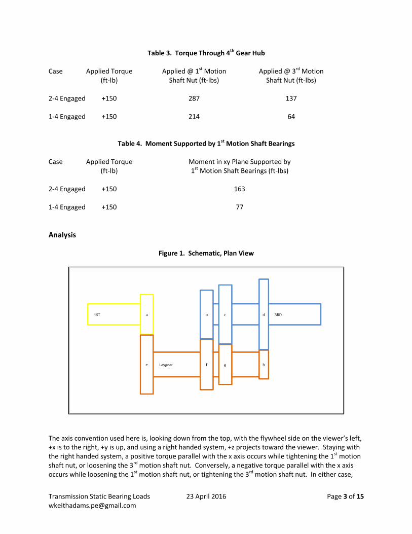
Table 3. Torque Through 4th Gear Hub Case Applied Torque Applied @ 1st Motion Applied @ 3rd Motion (ft-lb) Shaft Nut (ft-lbs) Shaft Nut (ft-lbs) 2-4 Engaged +150 287 137 1-4 Engaged +150 214 64
Table 4. Moment Supported by 1st Motion Shaft Bearings Case Applied Torque Moment in xy Plane Supported by (ft-lb) 1st Motion Shaft Bearings (ft-lbs) 2-4 Engaged +150 163 1-4 Engaged +150 77
Analysis
Figure 1. Schematic, Plan View
The axis convention used here is, looking down from the top, with the flywheel side on the viewer’s left, +x is to the right, +y is up, and using a right handed system, +z projects toward the viewer. Staying with the right handed system, a positive torque parallel with the x axis occurs while tightening the 1st motion shaft nut, or loosening the 3rd motion shaft nut. Conversely, a negative torque parallel with the x axis occurs while loosening the 1st motion shaft nut, or tightening the 3rd motion shaft nut. In either case,

Transmission Static Bearing Loads 23 April 2016 Page 4 of 15 [email protected]
the resulting forces at the teeth are equivalent, but the torque supported through the fourth gear hub does depend on which nut the torque is applied. In their product catalog (E1419c 2007 E-11), NSK has caged roller bearings dimensionally close to those in the MkII Mini laygear. The basic radial static load rating (Cor) for the flywheel-end bearing, NSK FWF-202613, is 15.5 kN, or 3485 lbs. There are two bearings, tandem, in the assembly. For the differential-end bearing, NSK FWF-162126, the basic radial static load rating is 23.6 kN, or 6654 lbs. These ratings are based on the assumption that the inner and outer surfaces are produced to the bearing manufacturer specifications for dimensions, out-of-round, finish, hardness, and other factors. The basic static radial load rating is based on ISO76:2006, which actually allows for some permanent (plastic) deformation on the order of 0.0001 of the rolling element diameter. The permissible static radial load is diminished by values in a table (2.4.2 Permissible Static Load Factor, Table 2.3) that depend on the end use requirements for operating smoothness. For the “low noise application,” the permissible static radial load must be less than one third of the basic static radial load rating, and is used here. Pitch Circle Figure 1 is a schematic of the plan view, looking front to rear, of a classic Mini transmission gear set. Each gear is labeled for notation of the various forces and moments. The radius drawn for each gear is of the pitch circle, which in turn is calculated from the center-to-center distance between the main shaft assembly and the laygear, and the number of teeth in each mating pair.
𝑅𝑖 = (𝑦1𝑠𝑡 − 𝑦𝑙𝑔) (𝑁𝑖
𝑁𝑖+𝑁𝑗) (1)
Where: 𝑅𝑖 = 𝑃𝑖𝑡𝑐ℎ 𝑐𝑖𝑟𝑐𝑙𝑒 𝑟𝑎𝑑𝑖𝑢𝑠 𝑜𝑓 𝑔𝑒𝑎𝑟 "𝑖" 𝑁𝑖 = 𝑁𝑢𝑚𝑏𝑒𝑟 𝑜𝑓 𝑡𝑒𝑒𝑡ℎ 𝑜𝑛 𝑔𝑒𝑎𝑟 "𝑖" 𝑁𝑗 = 𝑁𝑢𝑚𝑏𝑒𝑟 𝑜𝑓 𝑡𝑒𝑒𝑡ℎ 𝑜𝑛 𝑡ℎ𝑒 𝑔𝑒𝑎𝑟 "j" 𝑤ℎ𝑖𝑐ℎ 𝑚𝑎𝑡𝑒𝑠 𝑤𝑖𝑡ℎ 𝑔𝑒𝑎𝑟 i
(𝑦1𝑠𝑡 − 𝑦𝑙𝑔) = 𝑑𝑖𝑠𝑡𝑎𝑛𝑐𝑒 𝑏𝑒𝑡𝑤𝑒𝑒𝑛 1𝑠𝑡 𝑚𝑜𝑡𝑖𝑜𝑛 𝑠ℎ𝑎𝑓𝑡 𝑎𝑛𝑑 𝑙𝑎𝑦𝑠ℎ𝑎𝑓𝑡 𝑐𝑒𝑛𝑡𝑒𝑟𝑙𝑖𝑛𝑒𝑠
Gear Tooth Transmitted Force With any, and only, two gears simultaneously engaged, the mobility of the assembly is zero, and is statically determinate. The transmitted forces at the gear meshes can be readily calculated, and from them, the additional forces due to the involute gear pressure angle and helix angle can be determined. Vector addition of these components and the use of superposition can be used to find the forces and moments acting on the bearings. With the 1st and 3rd motion shafts locked together with the fourth gear hub, the mainshaft is treated as a single element. The sums of the moments parallel with the x axis through the mainshaft and the layshaft must equal zero.
Transmission Static Bearing Loads 23 April 2016 Page 5 of 15 [email protected]
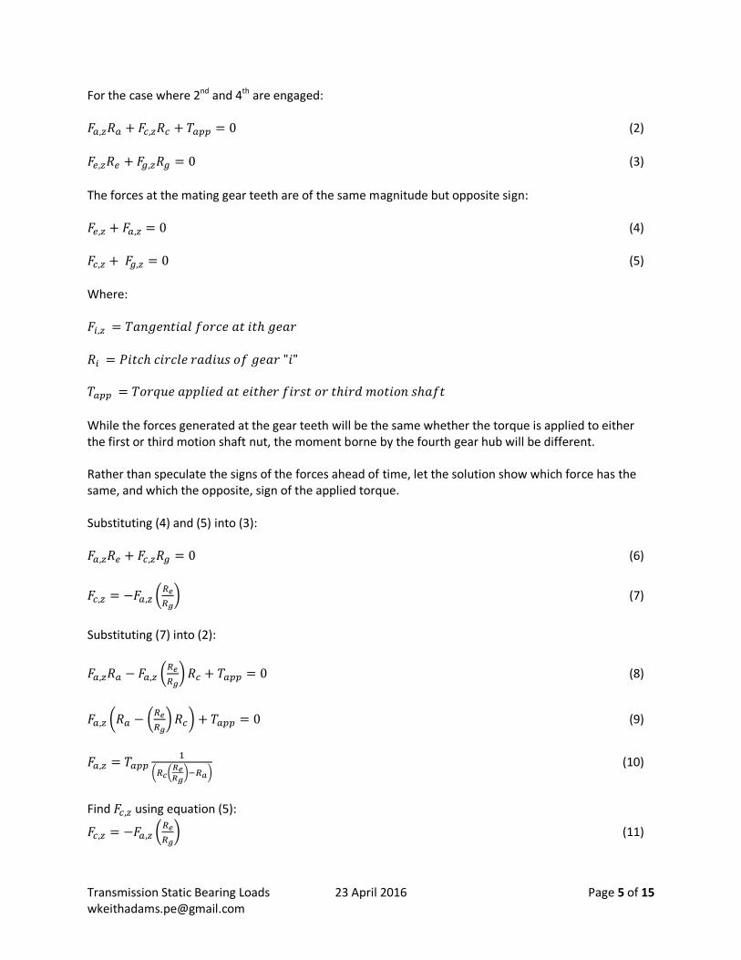
For the case where 2nd and 4th are engaged: 𝐹𝑎,𝑧𝑅𝑎 + 𝐹𝑐,𝑧𝑅𝑐 + 𝑇𝑎𝑝𝑝 = 0 (2)
𝐹𝑒,𝑧𝑅𝑒 + 𝐹𝑔,𝑧𝑅𝑔 = 0 (3)
The forces at the mating gear teeth are of the same magnitude but opposite sign: 𝐹𝑒,𝑧 + 𝐹𝑎,𝑧 = 0 (4) 𝐹𝑐,𝑧 + 𝐹𝑔,𝑧 = 0 (5)
Where: 𝐹𝑖,𝑧 = 𝑇𝑎𝑛𝑔𝑒𝑛𝑡𝑖𝑎𝑙 𝑓𝑜𝑟𝑐𝑒 𝑎𝑡 𝑖𝑡ℎ 𝑔𝑒𝑎𝑟
𝑅𝑖 = 𝑃𝑖𝑡𝑐ℎ 𝑐𝑖𝑟𝑐𝑙𝑒 𝑟𝑎𝑑𝑖𝑢𝑠 𝑜𝑓 𝑔𝑒𝑎𝑟 "𝑖" 𝑇𝑎𝑝𝑝 = 𝑇𝑜𝑟𝑞𝑢𝑒 𝑎𝑝𝑝𝑙𝑖𝑒𝑑 𝑎𝑡 𝑒𝑖𝑡ℎ𝑒𝑟 𝑓𝑖𝑟𝑠𝑡 𝑜𝑟 𝑡ℎ𝑖𝑟𝑑 𝑚𝑜𝑡𝑖𝑜𝑛 𝑠ℎ𝑎𝑓𝑡
While the forces generated at the gear teeth will be the same whether the torque is applied to either the first or third motion shaft nut, the moment borne by the fourth gear hub will be different. Rather than speculate the signs of the forces ahead of time, let the solution show which force has the same, and which the opposite, sign of the applied torque. Substituting (4) and (5) into (3): 𝐹𝑎,𝑧𝑅𝑒 + 𝐹𝑐,𝑧𝑅𝑔 = 0 (6)
𝐹𝑐,𝑧 = −𝐹𝑎,𝑧 (𝑅𝑒
𝑅𝑔) (7)
Substituting (7) into (2):
𝐹𝑎,𝑧𝑅𝑎 − 𝐹𝑎,𝑧 (𝑅𝑒
𝑅𝑔) 𝑅𝑐 + 𝑇𝑎𝑝𝑝 = 0 (8)
𝐹𝑎,𝑧 (𝑅𝑎 − (𝑅𝑒
𝑅𝑔) 𝑅𝑐) + 𝑇𝑎𝑝𝑝 = 0 (9)
𝐹𝑎,𝑧 = 𝑇𝑎𝑝𝑝1
(𝑅𝑐(𝑅𝑒𝑅𝑔
)−𝑅𝑎) (10)
Find 𝐹𝑐,𝑧 using equation (5):
𝐹𝑐,𝑧 = −𝐹𝑎,𝑧 (𝑅𝑒
𝑅𝑔) (11)
Transmission Static Bearing Loads 23 April 2016 Page 6 of 15 [email protected]
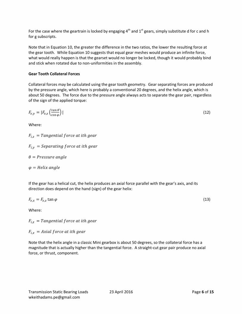
For the case where the geartrain is locked by engaging 4th and 1st gears, simply substitute d for c and h for g subscripts. Note that in Equation 10, the greater the difference in the two ratios, the lower the resulting force at the gear tooth. While Equation 10 suggests that equal gear meshes would produce an infinite force, what would really happen is that the gearset would no longer be locked, though it would probably bind and stick when rotated due to non-uniformities in the assembly. Gear Tooth Collateral Forces Collateral forces may be calculated using the gear tooth geometry. Gear separating forces are produced by the pressure angle, which here is probably a conventional 20 degrees, and the helix angle, which is about 50 degrees. The force due to the pressure angle always acts to separate the gear pair, regardless of the sign of the applied torque:
𝐹𝑒,𝑦 = |𝐹𝑒,𝑧 (𝑡𝑎𝑛 𝜃
cos 𝜑) | (12)
Where: 𝐹𝑖,𝑧 = 𝑇𝑎𝑛𝑔𝑒𝑛𝑡𝑖𝑎𝑙 𝑓𝑜𝑟𝑐𝑒 𝑎𝑡 𝑖𝑡ℎ 𝑔𝑒𝑎𝑟 𝐹𝑖,𝑦 = 𝑆𝑒𝑝𝑎𝑟𝑎𝑡𝑖𝑛𝑔 𝑓𝑜𝑟𝑐𝑒 𝑎𝑡 𝑖𝑡ℎ 𝑔𝑒𝑎𝑟
𝜃 = 𝑃𝑟𝑒𝑠𝑠𝑢𝑟𝑒 𝑎𝑛𝑔𝑙𝑒 𝜑 = 𝐻𝑒𝑙𝑖𝑥 𝑎𝑛𝑔𝑙𝑒 If the gear has a helical cut, the helix produces an axial force parallel with the gear’s axis, and its direction does depend on the hand (sign) of the gear helix: 𝐹𝑒,𝑥 = 𝐹𝑒,𝑧 tan 𝜑 (13)
Where: 𝐹𝑖,𝑧 = 𝑇𝑎𝑛𝑔𝑒𝑛𝑡𝑖𝑎𝑙 𝑓𝑜𝑟𝑐𝑒 𝑎𝑡 𝑖𝑡ℎ 𝑔𝑒𝑎𝑟 𝐹𝑖,𝑥 = 𝐴𝑥𝑖𝑎𝑙 𝑓𝑜𝑟𝑐𝑒 𝑎𝑡 𝑖𝑡ℎ 𝑔𝑒𝑎𝑟
Note that the helix angle in a classic Mini gearbox is about 50 degrees, so the collateral force has a magnitude that is actually higher than the tangential force. A straight-cut gear pair produce no axial force, or thrust, component.
Transmission Static Bearing Loads 23 April 2016 Page 7 of 15 [email protected]
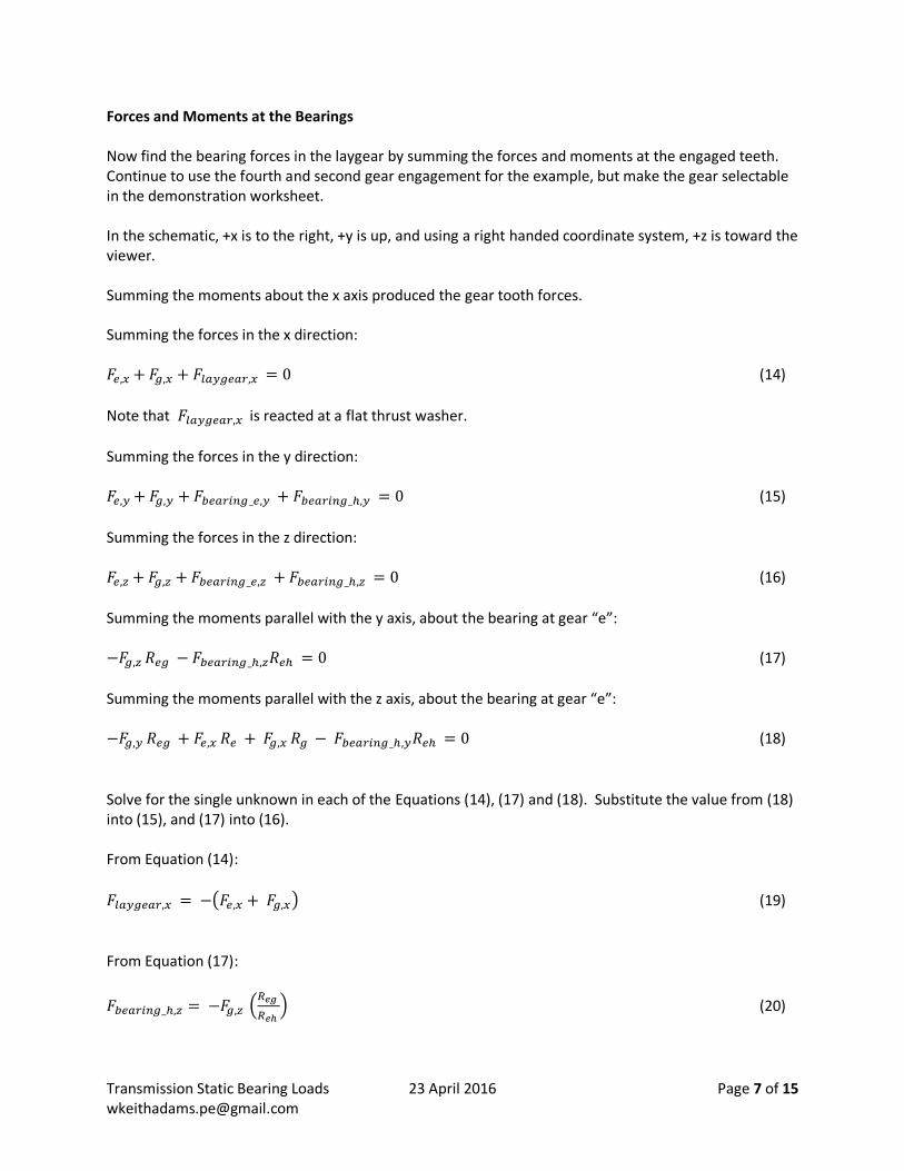
Forces and Moments at the Bearings Now find the bearing forces in the laygear by summing the forces and moments at the engaged teeth. Continue to use the fourth and second gear engagement for the example, but make the gear selectable in the demonstration worksheet. In the schematic, +x is to the right, +y is up, and using a right handed coordinate system, +z is toward the viewer. Summing the moments about the x axis produced the gear tooth forces. Summing the forces in the x direction: 𝐹𝑒,𝑥 + 𝐹𝑔,𝑥 + 𝐹𝑙𝑎𝑦𝑔𝑒𝑎𝑟,𝑥 = 0 (14)
Note that 𝐹𝑙𝑎𝑦𝑔𝑒𝑎𝑟,𝑥 is reacted at a flat thrust washer.
Summing the forces in the y direction: 𝐹𝑒,𝑦 + 𝐹𝑔,𝑦 + 𝐹𝑏𝑒𝑎𝑟𝑖𝑛𝑔_𝑒,𝑦 + 𝐹𝑏𝑒𝑎𝑟𝑖𝑛𝑔_ℎ,𝑦 = 0 (15)
Summing the forces in the z direction: 𝐹𝑒,𝑧 + 𝐹𝑔,𝑧 + 𝐹𝑏𝑒𝑎𝑟𝑖𝑛𝑔_𝑒,𝑧 + 𝐹𝑏𝑒𝑎𝑟𝑖𝑛𝑔_ℎ,𝑧 = 0 (16)
Summing the moments parallel with the y axis, about the bearing at gear “e”: −𝐹𝑔,𝑧 𝑅𝑒𝑔 − 𝐹𝑏𝑒𝑎𝑟𝑖𝑛𝑔_ℎ,𝑧𝑅𝑒ℎ = 0 (17)
Summing the moments parallel with the z axis, about the bearing at gear “e”: −𝐹𝑔,𝑦 𝑅𝑒𝑔 + 𝐹𝑒,𝑥 𝑅𝑒 + 𝐹𝑔,𝑥 𝑅𝑔 − 𝐹𝑏𝑒𝑎𝑟𝑖𝑛𝑔_ℎ,𝑦𝑅𝑒ℎ = 0 (18)
Solve for the single unknown in each of the Equations (14), (17) and (18). Substitute the value from (18) into (15), and (17) into (16). From Equation (14):
𝐹𝑙𝑎𝑦𝑔𝑒𝑎𝑟,𝑥 = −(𝐹𝑒,𝑥 + 𝐹𝑔,𝑥) (19)
From Equation (17):
𝐹𝑏𝑒𝑎𝑟𝑖𝑛𝑔_ℎ,𝑧 = −𝐹𝑔,𝑧 (𝑅𝑒𝑔
𝑅𝑒ℎ ) (20)

Transmission Static Bearing Loads 23 April 2016 Page 8 of 15 [email protected]
From Equation (18):
𝐹𝑏𝑒𝑎𝑟𝑖𝑛𝑔_ℎ,𝑦 = (1
𝑅𝑒ℎ ) (−𝐹𝑔,𝑦 𝑅𝑒𝑔 + 𝐹𝑒,𝑥 𝑅𝑒 + 𝐹𝑔,𝑥 𝑅𝑔 ) (21)
Rearranging Equation (15):
𝐹𝑏𝑒𝑎𝑟𝑖𝑛𝑔_𝑒,𝑦 = −(𝐹𝑒,𝑦 + 𝐹𝑔,𝑦 + 𝐹𝑏𝑒𝑎𝑟𝑖𝑛𝑔_ℎ,𝑦 ) (22)
Rearranging Equation (16):
𝐹𝑏𝑒𝑎𝑟𝑖𝑛𝑔_𝑒,𝑧 = −(𝐹𝑒,𝑧 + 𝐹𝑔,𝑧 + 𝐹𝑏𝑒𝑎𝑟𝑖𝑛𝑔_ℎ,𝑧 ) (23)
Since the force components are orthogonal, the resultant magnitudes are the square root of the sums of the squares:
|𝐹𝑏𝑒𝑎𝑟𝑖𝑛𝑔_𝑒| = √(𝐹𝑏𝑒𝑎𝑟𝑖𝑛𝑔_𝑒,𝑦)2
+ (𝐹𝑏𝑒𝑎𝑟𝑖𝑛𝑔_𝑒,𝑧)2
(24)
|𝐹𝑏𝑒𝑎𝑟𝑖𝑛𝑔_ℎ| = √(𝐹𝑏𝑒𝑎𝑟𝑖𝑛𝑔_ℎ,𝑦)2
+ (𝐹𝑏𝑒𝑎𝑟𝑖𝑛𝑔_ℎ,𝑧)2
(25)
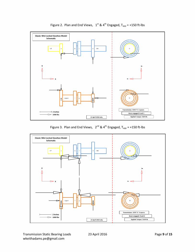
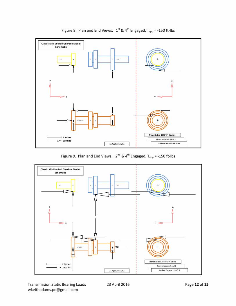
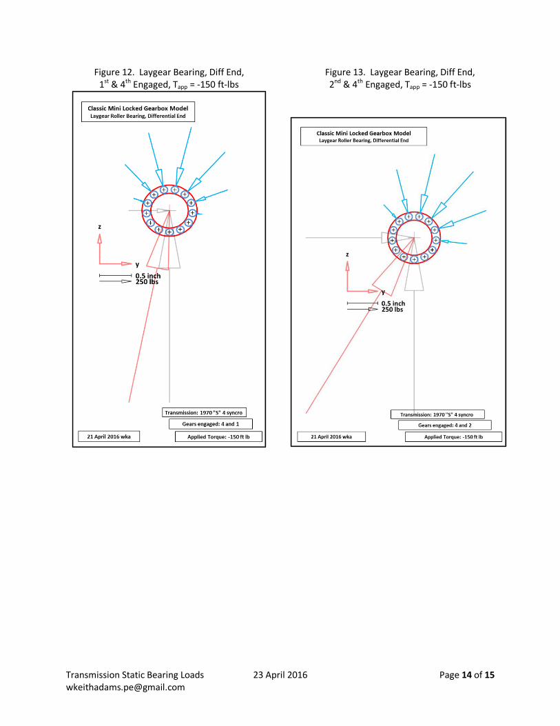
Scaled Schematics The equations were coded in VBA for Excel. A few schematics with scaled force vectors, that is, the force arrows sizes are proportional with the force magnitudes, show the plan and end views of the main and lay shafts, with details of the laygear roller bearings. All combinations of (1st & 4th) and (2nd & 4th) gear locked cases, and +150 ft-lb and -150 ft-lb applied torques, are included.
Transmission Static Bearing Loads 23 April 2016 Page 9 of 15 [email protected]
Figure 2. Plan and End Views, 1st & 4th Engaged, Tapp = +150 ft-lbs
Figure 3. Plan and End Views, 2nd & 4th Engaged, Tapp = +150 ft-lbs

Transmission Static Bearing Loads 23 April 2016 Page 10 of 15 [email protected]
Figure 4. Laygear Bearing, Flywheel End, 1st & 4th Engaged, Tapp = +150 ft-lbs
Figure 5. Laygear Bearing, Flywheel End, 2nd & 4th Engaged, Tapp = +150 ft-lbs

Transmission Static Bearing Loads 23 April 2016 Page 11 of 15 [email protected]
Figure 6. Laygear Bearing, Diff End, Figure 7. Laygear Bearing, Diff End, 1st & 4th Engaged, Tapp = +150 ft-lbs 2nd & 4th Engaged, Tapp = +150 ft-lbs
Transmission Static Bearing Loads 23 April 2016 Page 12 of 15 [email protected]
Figure 8. Plan and End Views, 1st & 4th Engaged, Tapp = -150 ft-lbs
Figure 9. Plan and End Views, 2nd & 4th Engaged, Tapp = -150 ft-lbs

Transmission Static Bearing Loads 23 April 2016 Page 13 of 15 [email protected]
Figure 10. Laygear Bearing, Flywheel End, 1st & 4th Engaged, Tapp = -150 ft-lbs
Figure 11. Laygear Bearing, Flywheel End, 2nd & 4th Engaged, Tapp = -150 ft-lbs
Transmission Static Bearing Loads 23 April 2016 Page 14 of 15 [email protected]
Figure 12. Laygear Bearing, Diff End, Figure 13. Laygear Bearing, Diff End, 1st & 4th Engaged, Tapp = -150 ft-lbs 2nd & 4th Engaged, Tapp = -150 ft-lbs

Transmission Static Bearing Loads 23 April 2016 Page 15 of 15 [email protected]
Acknowledgements Lynn S, for the tote full of 3 synchro “B” box parts, and the case for demonstrations Paul S, for letting me measure a cluster gear from his collection Versions 20160423 First distribution 20160427 Correct source for Equation (8): (2) not (1), (7) not (6)