Class Note - Concrete (Moddified 10-01-2069)
63
CLASS NOTES ON CONCRETE TECHNOLOGY
-
Upload
sujan-singh -
Category
Documents
-
view
37 -
download
0
description
concrete
Transcript of Class Note - Concrete (Moddified 10-01-2069)

CLASS NOTES
ON
CONCRETE TECHNOLOGY

Class notes on Concrete Technology (P -1) Er. Sudip Karanjit – Khwopa Engineering College
1.0 INTRODUCTION
1.1 CONCRETE AS STRUCTURAL MATERIAL:
At present concrete is one of the most widely used material in the world (˜12 billion ton per
year). Human consume no material in such a tremendous quantity except water. Due to its
ease of use and wide range of applicability in structural & nonstructural component, its
quantity & application area is growing more & more. Presently some of the areas of
application are listed below:
i) Building: Various structural & nonstructural components.
ii) Bridge: Including pier & super structures.
iii) Steel structure: Foundation base for various steel structures.
iv) Tunnel / Underground Structures.
v) Slope Stabilization: Shotcreting / Ground retaining structures.
vi) Offshore Structure: Various marine structures for oil/gas extraction.
vii) Nuclear Shield: As concrete is excellent in protection of radiation.
viii) Refractory: High temperature application.
ix) Fire Proofing: Widely used in fireproofing of steel structure.
x) Reinforced/ precast/ prestressed concrete components: Various new technology of
use of concrete, making its use more popular & wider. Etc.
1.2 COMPONENT OF MODERN CONCRETE:
i) Cement.
ii) Aggregate (Fine / Coarse)
iii) Water.
iv) Admixture.
v) Other additives.
1.3 TYPES OF CONCRETE:
I) Based on compressive strength:
a) Low Strength: fck < 20 Mpa
b) Medium Strength: fck = 20 – 40Mpa
c) High Strength: fck >40 Mpa
fck = 28days characteristic strength
of concrete.

Class notes on Concrete Technology (P -2) Er. Sudip Karanjit – Khwopa Engineering College
II) Based on Unit weight:
a) Normal weight concrete: Concrete having unit wt. in between 1800 – 3200kg/m3 is
treated as normal wt concrete. Mostly used concrete in our practice have in average
2400kg/m3.
b) Light weight concrete: Concrete having unit wt. in between 300 – 1800kg/m3. Used
for non structural & lightly loaded structural component. Can further classified into :
Light wt. Aggregate concrete: Produced using light wt. aggregate.
Light wt. Aerated concrete: Produced introducing air bubble in concrete using
chemicals.
Light wt. No fine concrete: Produce without using fine aggregate.
c) Heavy weight concrete: Concrete having unit wt. > 3200 kg/ m3. Use heavy wt.
natural aggregates as well as steel aggregate. Used in nuclear plant as radiation shield.
# Other Special types (depending upon material used):
III) Sulphur infiltrated conctere: This concreting process involves the impregnation of
sulphur into concrete by various methods. Improvement in physical property has been
reported several hundred times. Can be used in precast concrete elements.
IV) Fibre reinforced concrete: As we know concrete is fairly good in compression but
its tensile strength is very less so as to improve the same various types of fibers are being
used in concreting (these fibers are mixed with other ingredient in green stage). Normally
have diameter 0.25 – 0.75mm & length to dia. ratio 30 – 150. Eg: steel fiber, glass fiber,
carbon fiber etc.
V) Polymer Concrete: This concreting process involves the impregnation of polymer
into concrete or by mixing it in green stage. Can be used in precast concrete elements &
marine structure where high durability required against corrosive environment.
VI) Ferrocement: Ferrocement is considered as a new material consists of cement sand
mortar & wiremesh. The cement mortar used is with cement: sand ratio 1:2 to 1:3 with
W/C 0.40 to 0.45 & wiremesh 0.5 to 1.0mm dia @ 5 – 10mm spacing. Very thin section
can be formed with this material (2-3cm thk.). Now a days its widely used in construction
of water tanks, manway cover, pressure pipes, various architecture shape etc.
VII) Bacterial Concrete: Bacteria called bacillus pasteruii develops calcite (CaCO3)
during its metabolism which can be utilized as cementing material for sealing crack in
concrete & rock structures. As calcium carbonate is the natural & environmental friendly
cementing / bounding agent, above bacteria is utilized to fill the crack ( in natural rock
strata / oil well etc ) mixing with sand and silica fume.

Class notes on Concrete Technology (P -3) Er. Sudip Karanjit – Khwopa Engineering College
# Other Special types (depending upon application method):
VIII) Guniting / Shotcreting: Concreting process in which concrete is pneumatically
projected to surface at high velocity. Normally used in tunnel lining, refractory
concreting, slope stabilization & numerous other application where placing of formwork
is difficult.
IX) Vacuum Concrete: As we know higher the W/C ratio higher the workability of
concrete but it results low strength concrete in harden concrete. In this concreting process,
concrete is initially placed with higher W/C ratio & immediately after placing, excess
water is removed through special equipment setup (through vacuum process).
Fig; Vacuum Concreting.
X) Roller Compacted Concrete: Roller compacted concrete is mainly no slump, almost
dry concrete compacted by vibrator roller. This type of concrete is mainly used in dam &
other mass concreting process. Concrete is placed in thin layers (20-30cm) to allow
complete compaction. Cement content ranges from 60 - 360kg/m3.

Class notes on Concrete Technology (P -4) Er. Sudip Karanjit – Khwopa Engineering College
XI) Self Compacted Concrete: This type of concrete is designed to flow under its own
weight with very high degree of workability. Max. aggregate size is limited to 20mm &
uses HRWR (High Range Water Reducing admixture). This type of concrete is
extensively used in many projects due to: it easiness & speed in placing, reduced
manpower, good surface finish and durability etc.
1.4 PROPERTIES OF HARDEN CONCRETE:
i) Strength (Compressive & Tensile)
ii) Durability
iii) Modulus of Elasticity
iv) Poisons ratio
v) Thermal Property

Class notes on Concrete Technology (P -5) Er. Sudip Karanjit – Khwopa Engineering College
2.0 AGGREGATE
Aggregate is one of the main constituent of concrete which occupy around 70 – 80% of the
body of concrete. Variation in aggregate property also affects the property of concrete
(Strength, workability & durability).
2.1 SOURCE AND CLASSIFICATION:
I) Depending upon its Origin aggregate can be classified into:
a) Natural aggregate: Aggregate derived from natural source (eg, quarries or river) by
blasting, crushing or screening. Can be further classified into:
Igneous: Normally all type of aggregate from igneous rock source is considered
suitable for concreting.
Metamorphic: As aggregate from metamorphic rock source shows weak plane of
foliation is not considered very suitable but aggregate like quartzite & gneiss still
produce good concrete of its class.
Sedimentary: The quality of aggregate from sedimentary rock source varies
considerably depending upon the pressure in which original rock is compacted &
cementing material in it. Normally limestone, siliceous sandstone can produce good
quality concrete.
b) Artificial aggregate: Artificially made aggregate for special concrete or industrial
byproducts.
Clean broken bricks: Obtained by cleaning broken bricks. Not suitable for wear & tear
surface & can be used in low to medium strength concreting.
Blast furnace slag: This is the byproduct of pig iron in blast furnace.
Steel shots: Steel aggregate made for high density concrete. Used in nuclear plants.
II) Depending upon its Unit wt.:
a) Light wt.: Aggregate with sp. gravity< 2.5. Used to produce concrete with unit weight
upto 1200kg/m3.
b) Medium wt.: Aggregate with sp gr. 2.5-2.7. Commonly used in construction. Produce
concrete with unit wt. 2300-2600kg/m3.
c) Heavy wt.: Aggregate with sp gr. >2.7. Normally used in radiation shield. Eg, ferro-
phosphorus 5.8-6.8, magnetite 4.2-5.2, iron shots 6.2 - 7.8 sp gr.
III) According to its Size:
a) Fine Aggregate: Normally aggregate passing through 4.75mm sieve is considered as
fine aggregate. IS383:1970 further classified this into various zone depending upon its
fineness.
b) Coarse Aggregate: Normally aggregate retained on 4.75mm sieve is considered as
coarse aggregate. Coarse aggregate is normally represented by is nominal max size.
Class notes on Concrete Technology (P -6) Er. Sudip Karanjit – Khwopa Engineering College
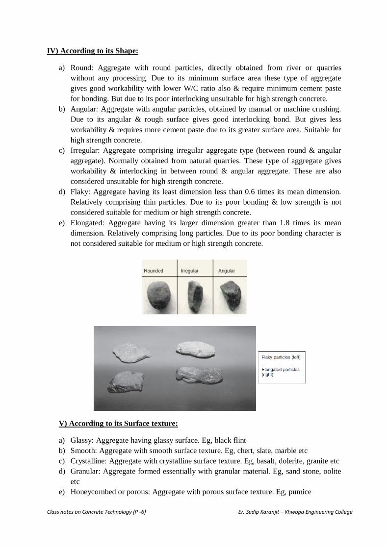
IV) According to its Shape:
a) Round: Aggregate with round particles, directly obtained from river or quarries
without any processing. Due to its minimum surface area these type of aggregate
gives good workability with lower W/C ratio also & require minimum cement paste
for bonding. But due to its poor interlocking unsuitable for high strength concrete.
b) Angular: Aggregate with angular particles, obtained by manual or machine crushing.
Due to its angular & rough surface gives good interlocking bond. But gives less
workability & requires more cement paste due to its greater surface area. Suitable for
high strength concrete.
c) Irregular: Aggregate comprising irregular aggregate type (between round & angular
aggregate). Normally obtained from natural quarries. These type of aggregate gives
workability & interlocking in between round & angular aggregate. These are also
considered unsuitable for high strength concrete.
d) Flaky: Aggregate having its least dimension less than 0.6 times its mean dimension.
Relatively comprising thin particles. Due to its poor bonding & low strength is not
considered suitable for medium or high strength concrete.
e) Elongated: Aggregate having its larger dimension greater than 1.8 times its mean
dimension. Relatively comprising long particles. Due to its poor bonding character is
not considered suitable for medium or high strength concrete.
V) According to its Surface texture:
a) Glassy: Aggregate having glassy surface. Eg, black flint
b) Smooth: Aggregate with smooth surface texture. Eg, chert, slate, marble etc
c) Crystalline: Aggregate with crystalline surface texture. Eg, basalt, dolerite, granite etc
d) Granular: Aggregate formed essentially with granular material. Eg, sand stone, oolite
etc
e) Honeycombed or porous: Aggregate with porous surface texture. Eg, pumice

Class notes on Concrete Technology (P -7) Er. Sudip Karanjit – Khwopa Engineering College
2.2 GRADING OF AGGREGATE (IS Code):
Particle size distribution of aggregate is also termed as grading of aggregate. According to IS
code there is two types of aggregate according to their size.
a) Fine Aggregate: Aggregate passing through 4.75mm sieve is considered as fine
aggregate. IS383:1970 further classified this into various zone depending upon its
fineness. Zone I represents the course while Zone IV represents the finer sand.
Workability & uniformity of concrete is affected by its grading.
IS 383:1970 – Aggregate Grading Table.
Fine Aggregate
b) Coarse Aggregate: Normally aggregate retained on 4.75mm sieve is considered as
coarse aggregate. There is two types of grading as per IS IS383:1970, Single sized &
Graded coarse aggregate.
Single sized coarse aggregate may have its nominal size 63, 40, 20, 16, 12.5 and 10 mm.
While graded coarse aggregates are comprise of various size to have densely packed
system. Gradiation limit for single sized & graded aggregates are given below:

Class notes on Concrete Technology (P -8) Er. Sudip Karanjit – Khwopa Engineering College
Coarse Aggregate- Single Sized aggregate & Graded aggregate As Per IS 383:1970
All in aggregate: Aggregate having different fraction of fine & coarse aggregate to achive minimum void thus
max. compaction while concreting. Grading limit of all in aggregate as given by IS383:1970
is given below:
Grading Limit of all in Aggregate aggregate As Per IS 383:1970
2.3 AGGREGATE PROPERTIES & METHOD OF TESTING:
Refer related books/class notes for detail mechanical/thermal properties. Here we discuss
only about some important / significant properties that affects concrete in green & its harden
stage.

Class notes on Concrete Technology (P -9) Er. Sudip Karanjit – Khwopa Engineering College
FLAKYNESS INDEX: can be define as percentages by weight of particle with least
dimension (thickness) less than 0.6 times its mean dimension. (Not applicable for particle size
less than 6.3mm)
ELONGATION INDEX: can be define as percentages by weight of particle with largest
dimension (length) more than 1.8 times its mean dimension.
BULKING OF SAND:
Free moisture content in aggregate results in the increase in volume of aggregate also
termed as bulking of aggregate. Any moisture content at the surface of aggregate cause
repulsive force to neighboring aggregate (due to surface tension) which cause increase in
volume of aggregate. This force mainly depends upon the moisture content & size of the
aggregate,
Higher the aggregate size less the effect of bulking phenomenon.
While at particular moisture content bulking take its highest value.
Due to bulking, aggregate shows very unrealistic volume which affects the proportioning of
aggregates. Fine aggregate may have volume increse upto 40% of its actual volume due to
bulking. So the extreme care needs to be taken while performing volumetric proportioning of
concrete.

Class notes on Concrete Technology (P -10) Er. Sudip Karanjit – Khwopa Engineering College
ALKALI AGGREGATE REACTION:
Aggregates are normally inert material but some aggregate may contain reactive silica which
reacts with alkalies (Sodium / Potasium oxide) present in cement called alkali aggregate
reaction.
In USA must of the structure failures are reported due to this type of reaction.
Reaction stars with attack on reactive siliceous mineral in aggregate by alkaline hydroxide
derived from alkalies in cement. This produce alkali-silica gel with unlimited swelling which
results spreading patterned crack on concrete.
Factors affecting alkali aggregate reaction:
a) Reactive aggregate type: The main cause of alkali aggregate reaction is the presence of
reactive silica in aggregate. Without the presence of reactive silica alkali aggregfate
reaction will not be possible.
b) Alkali content in cement: Another factor that initiates reaction is alkali content in cement.
Lower alkali content greatly reduce the possibility of alkali aggregate reaction. For the
same reason IS Code has limited the alkali content of cement to 0.6%.
c) Moisture availability: Alkali aggregate reaction requires moisture for its initiation, lesser
the available moisture less the chances of this reaction.
d) Optimum temperature: Alkali aggregate reaction finds temperature of 10 – 38 deg C
much favorable for its reaction.

Class notes on Concrete Technology (P -11) Er. Sudip Karanjit – Khwopa Engineering College
3.0 CEMENT
3.1 DEFINATION AND MANUFACTURING PROCESS:
Cement is considered as one of the most important constituent of concrete as it acts as
binding agent to whole concrete mass.
Property of cement greatly affects the property of concrete; in harden stage as well as in
green stage.
Modern Cement also called Ordinary Portland Cement (as it resembles in colour &
quality with Portland Stone in Dorset, UK).
Primary constituent of Portland cement are:
Calcareous material (Lime Stone, Chalk)
Argillaceous/Siliceous material (Clay, Shale etc)
Process of manufacture of cement consists:
Proportioning of raw material
Grinding & intimate Mixing
Burning in kiln at 1300-1500 deg C (which form fused nodular shape clinker, which
after cooling is ground as fine powder mixing 3-5% gypsum)
Manufacture of cement can be carried out with two method (depending upon mixing &
grinding of raw material) :
a) Wet process: In wet process limestone from quarries crushed to smaller fragments &
is then taken into ball mill where it is mixed with clay or shale & converted to slurry
(creamy liquid) with addition of 35-50% water. Chemical composition of slurry is
then checked & corrected. The slurry is sprayed to rotary kiln against hot surface of
hanging chain. The slurry gets dry & undergoes series of chemical change. The
material gets fused at high temperature & converted into 3-20mm nodular form called
clinker. The clinker so formed is dropped in to cooler & stored in silo/bins. The
clinker is then ground to required fineness in ball-mill in addition of 3-5% gypsum.
b) Dry Process: In dry process raw materials are proportioned & mixing/grinding is
carried out in dry condition. Then is blended/corrected for its composition. By
addition of about 12% of water blended mass is converted in to pellets which permit
air flow & exchange of heat in rotary kiln. The mass is then charged into kiln (1300-
1500 deg C) to form clinker. The clinker so formed is dropped in to cooler & stored in
silo/bins. The clinker is then ground to required fineness in ball-mill in addition of 3-
5% gypsum.
As dry process is quite economic & energy efficient than wet process now a days
most of the plants are upgrading into the dry method of cement manufacture.

Class notes on Concrete Technology (P -12) Er. Sudip Karanjit – Khwopa Engineering College
Fig: Cement Manufacture Process
Fig: a) Cement Factory, b) Cement Clinker
Class notes on Concrete Technology (P -13) Er. Sudip Karanjit – Khwopa Engineering College
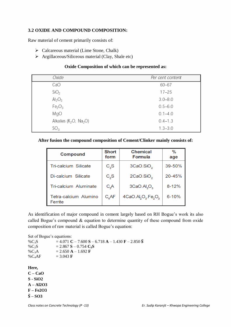
3.2 OXIDE AND COMPOUND COMPOSITION:
Raw material of cement primarily consists of:
Calcareous material (Lime Stone, Chalk)
Argillaceous/Siliceous material (Clay, Shale etc)
Oxide Composition of which can be represented as:
After fusion the compound composition of Cement/Clinker mainly consists of:
As identification of major compound in cement largely based on RH Bogue’s work its also
called Bogue’s compound & equation to determine quantity of these compound from oxide
composition of raw material is called Bogue’s equation:
Set of Bogue’s equations:
%C3S = 4.071 C – 7.600 S – 6.718 A – 1.430 F – 2.850 𝐒 %C2S = 2.867 S – 0.754 C3S
%C3A = 2.650 A – 1.692 F
%C4AF = 3.043 F
Here,
C – CaO
S - SiO2
A – Al2O3
F – Fe2O3
𝐒 – SO3

Class notes on Concrete Technology (P -14) Er. Sudip Karanjit – Khwopa Engineering College
Influence of Various compound in Cement:
Tri-calcium silicate C3S:
Mainly contributes the early strength of cement.
Produce high heat of hydration.
Quality/density of C-S-H gel produce from this compound is slightly inferior than from
C2S.
This compound produce more Ca(OH)2 than C2S.
Di-calcium silicate C2S:
Mainly contributes the later strength of cement.
Produce low heat of hydration.
C-S-H gel produce from this compound is dense and with high sp. surface.
This compound produce less Ca(OH)2 than C3S.
More durable than C3S in acidic & sulphur environment.
Tri-calcium aluminate C3A:
Strength contribution of this compound is negligible.
Very high heat of hydration.
This compound is characterized by its very fast reaction leading flash set of concrete; to
control its fast setting character gypsum is added to cement.
Produce C3AH6 cubical compound after hydration.
Harmful for durability as is likely to attack by sulphur.
Tetra-calcium alumino ferrite C4AF:
Strength contribution of this compound is negligible.
Produce high heat of hydration.
Produce C3FH6 after hydration.
Show more resistance to sulphate attack than C3A.

Class notes on Concrete Technology (P -15) Er. Sudip Karanjit – Khwopa Engineering College
C3A & C4AF in presence of gypsum hydrates to form calcium aluminate trisulphate hydrate
(C6AS3H32) also called “ettringite” & calcium aluminate monosulphate hydrate C4ASH18.
Rate of Hydration of various Compound Rate of Strength gain of various Compound
3.3 HYDRATION OF PORTLAND CEMENT:
Chemical reaction of cement with water is termed as hydration of cement which turns cement
into the binding material with strong adhesive property.
Various compound present in cement reacts individually with water to produce various
hydration products. The major compounds of hydration are C-S-H gel & Ca (OH)2.
a) Hydration C3S & C2S produce C-S-H gel & Ca(OH)2:
b) Hydration of C3A & C4AF:
2C3A+6H = 2C3AH6
C4AF + 2CH + 10H = C3AH6 + C3FH6
Where, C – CaO / S- SiO2 / A – Al2O3 /
F – Fe2O3 / H – H2O / CH- Ca(OH)2
C-S-H gel – C3S2H3 – 3Cao.SiO2.3H2O
C-S-H gel
C-S-H gel

Class notes on Concrete Technology (P -16) Er. Sudip Karanjit – Khwopa Engineering College
Hydration of C3A in presence of gypsum:
C3A+32H + 3CaSO4 = C6AS3H32 (tri-sulphate hydrate - “ettringite”)
C3A+ 18H + CaSO4 = C4ASH18 (mono-sulphate hydrate)
Addition of gypsum in cement control the flash set reaction of C3A. In presence of gypsum it
reacts with 32 molecule of water resulting large volume change. As this reaction takes place
in green stage of concrete, volume change will not be the problem. But if this takes place in
harden stage of concrete due to external sulphate environment or presence of excess of
gypsum in cement, the large volume change cause crack & detoriation in concrete called
sulphate attack.
Calcium Silicate Hydrate (C-S-H gel) : C-S-H gel is the most important & major product
obtained from hydration. It covers around 50-60% solid volume in completely hydrated paste.
It shows poorly crystalline fibrous mass. It exhibits the strength & binding property to
concrete.
Calcium Hydroxide (Ca(OH)2): Ca(OH)2 is not a desirable product in concrete mass but it
also covers around 20-25% solid volume. It shows distinctive hexagonal prism morphology.
It reacts with sulphate present in environment/water to form calcium sulphate which reacts
with C3A causing detoriation in concrete (also called Sulphate Attack). Ca(OH)2 is alkaline
in nature which maintain PH value of concrete around 13 & resists corrosion of
reinforcement.
Sulphate attack chemistry:
Ca(OH)2+ Sulphur compound = CaSO4
C3A+32H + 3CaSO4 = C6AS3H32 (tri-sulphate hydrate - “ettringite” – cause large volume
change & detoriation in harden concrete)
C-S-H gel
Ca(OH)2
C-S-H gel

Class notes on Concrete Technology (P -17) Er. Sudip Karanjit – Khwopa Engineering College
Fig: Various microscopic view of Hydrated Cement Paste
Structure of Hydrated Cement / Three phase system of Concrete:
Fresh paste acts like a plastic network of cement partical in water while harden paste at any
stage of hydration contains various compound called C-S-H gel , Ca(OH)2, ettringite & other
compounds. Harden concrete structure is normally considered as a 3-Phase system.
Paste phase: Paste phase is the most important phase of concrete as it influences the
overall behavior of harden concrete. Strength, durability, creep, shrinkage & elastic
property of concrete is greatly affected by paste structure of concrete. In microscopic
view it contains mainly dense network of fibrous C-S-H gel & hexagonal Ca(OH)2.
Aggregate phase: Aggregate phase is also one of the important phase of the concrete &
influence the overall strength of concrete but has less influence than paste phase in
property of concrete.
Transition zone phase: In micro level, between aggregate & paste phase another phase
can be visualized called transition zone phase. This is also called the plane of weakness &
greatly affects the mechanical behavior of concrete. Because of larger concentration of
crystalline compound like Ca(OH)2 & ettringite and also due to bleeding & water
accumulation along aggregate particles, these acts like a weak link in concrete. Due to
shrinkage & temperature variation transition zone develops micro crack and upon loading
the structure these cracks propagate causing failure of bond in concrete.
Water requirement for hydration:
It has been found that the C3S requires 24% of water for its hydration & C2S takes 21% of
water by weight of cement. In average cement requires around 23% of water by its weight.
This 23% of water required for the chemical reaction with cement is also called bound water.
Certain quantity of water also can be found within gel pore called gel water. About 15% of
water requires to fill up gel pore. It has been found that if the water require to fillup the gel-
pore is inadequate formation of gel itself will stop so bound-water & gel-water are also called
Concrete as
3- Phase System

Class notes on Concrete Technology (P -18) Er. Sudip Karanjit – Khwopa Engineering College
complementary. Total 38% (23%+15%) of water is required to complete the full hydration of
cement. If this quantity is not available complete hydration will not be possible. And also the
addition of water greater than this will cause unnecessary capillary pores in concrete.
Heat of hydration:
As we know the reaction of cement with water is
exothermic. It produce heat during its reaction, the rate
of hydration of various compound in cement is
different thus producing different amount of heat
during the way of reaction. The rapid initial rate of
heat liberation (Peak A in fig.) is due to the rapid
hydration of C3A/C3S while the reduction in heat
liberation occurs due to retardation of C3A cause by
gypsum. The next peak B is due to the reaction of C3S
/ formation of ettringite. While this rate of heat
evolution also decrese withtime.
Verbec & Foster had given the heat of hydration of
various compound after their extensive research &
tests as given below:
3.4 TYPES OF CEMENT:
ASTM (American Society of Testing Material) Classification:
Type I: Normal Cement Type: Also called general purpose cement Used in general
construction type where corrosive environment/ sulphur is not present & the special property
of cement is not required. C3A shall not exceed 15%. This is the most used type of cement in
all type of general construction.
The typical compound compositions: 55% (C3S), 19% (C2S), 10% (C3A), 7% (C4AF), 2.8%
MgO, 2.9% (SO3), 1.0% Ignition loss, and 1.0% free CaO.
Type II: Sulphate Resistance Cement: This type of cement is manufactured to have
moderate sulphate resistance. Normally used where moderate sulphate attack / moderate
corrosive environment is present. Used in underground concrete work & in presence of
ground water where sulphate may present. C3A content is limited to < 8% to control the
sulphate attack.
The typical compound compositions: 55% (C3S), 19% (C2S), 10% (C3A), 7% (C4AF), 2.8%
MgO, 2.9% (SO3), 1.0% Ignition loss, and 1.0% free CaO.

Class notes on Concrete Technology (P -19) Er. Sudip Karanjit – Khwopa Engineering College
TypeIII: High early strength: This cement is similar to Type I, but ground finer. In some
case C3S and C3A content is also increased to achive early strength. This gives the concrete
using this type of cement a three day compressive strength equal to the seven day
compressive strength types I. It may be used in emergency construction and repairs and
precast concrete job.
Its typical compound composition is: 57% (C3S), 19% (C2S), 10% (C3A), 7% (C4AF), 3.0%
MgO, 3.1% (SO3), 0.9% Ignition loss, and 1.3% free CaO.
TypeIV: Low heat of hydration: The percentages of (C2S) and (C4AF) are kept relatively
high and (C3S) and (C3A) are relatively low. This type of cement gives low heat of hydration
& rate of strength gain is also low. Suitable for mass concreting such as dam where low heat
of hydration is desirable.
Typical compound composition: 28% (C3S), 49% (C2S), 4% (C3A), 12% (C4AF), 1.8% MgO,
1.9% (SO3), 0.9% Ignition loss, and 0.8% free CaO.
TypeV: High Sulphate Resistance: This cement is manufactured with very low (C3A). The
maximum content of (C3A) allowed is 5%. Normally used where sulphate & alkali content is
high which react with (C3A) causing detoriation of concrete.
Its typical compound composition is: 38% (C3S), 43% (C2S), 4% (C3A), 9% (C4AF), 1.9%
MgO, 1.8% (SO3), 0.9% Ignition loss, and 0.8% free CaO.
TypeIS: (Type I + Slag): Manufactured with (Type I cement + blast furnance slag). Slag
content may varies from 25-70%. This type of cement gives low heat of hydration & better
corrosion resistance. But its strength gain is also slower.
TypeIP: (Type I + Pozzolona): Manufactured with intimate blending of Type I cement &
fine pozzolona. Pozzolona content may varies from 15-40%. This type of cement gives low
heat of hydration & better corrosion resistance. But its strength gain is also slower. Flyash,
Silica fume is common pozzolona material used to produce this type of cement.
TypeIA/IIA/IIIA: (Types I or II or III + air-entraining agent): Have the same
composition as types I, II, and III + air-entraining agent is ground into the mix. They
introduce the fine air bubble in concrete & increase workability / improve resistance to
freezing under low temperatures.
Types II(MH) and II(MH)a: have recently been added with a similar composition as types
II and IIa but with a mild heat.

Class notes on Concrete Technology (P -20) Er. Sudip Karanjit – Khwopa Engineering College
BIS (Bureau of Indian Standard) Classification:
a) Ordinary Portland Cement (OPC):
Extensively being used in general construction where corrosive environment/ sulphur
is not present & the special property of cement is not required.
Normally available in three different grade – 33grade, 43grade & 53grade.
b) Sulphate Resisting Cement:
Manufactured with low C3A content (<5%) & comparatively low C4AF to prevent
the sulphte attack reaction.
Used where environment (groung water/soil ) is corrosive & sulphur attack is present.
Normally used in foundation, buried pipeline & marine environment.
c) Rapid Hardening Cement:
Similar to OPC, but ground finer.
High C3S and low C2S content is maintained to achieve early strength.
Produce more heat of hydration, creates problem in mass concreting.
Can be used where high early strength is desirable Eg, Prefabrication, road repair,
cold weather.
d) Extra Rapid hardening Cement:
Manufactured with intergrinding Rapid hardening cement with calcium chloride
(CaCl2) < 2%.
Produce very high heat of hydration.
Can be used where very fast hardening is desirable.
In concreting mixing, transportation, placing & finishing needs to be done within
20min.
Storage of this type of cement shall not be greater than 1 month.
e) Low heat Cement:
Manufactured with low C3A & C3S and increased C2S.
Ideal for mass concreting where low heat is desirable.
Heat of hydration for 7days<65Cal/gm and for 28days< 75Cal/gm.
f) Super-sulphate Cement:
Manufactured with granulated slag (80-85%) + hard burnt gypsum (10-15%) + OPC
clinker (5%)
Used where high sulphate resistance is desirable.
Produce low heat of hydration.
Used where environment (groung water/soil ) is highly corrosive & sever sulphur
attack is present.

Class notes on Concrete Technology (P -21) Er. Sudip Karanjit – Khwopa Engineering College
g) Portland Slag Cement:
Manufacture intergrinding OPC clinker + gypsum + blast furnance slag (25-65%).
Slag need to be the ground granulated blast furnance slag (GGBS), presence
crystalline slag cause low quality cement.
Produce low heat of hydration, making ideal for mass concreting.
Better corrosion resistance.
But have slow strength development.
h) Portland Pozzolana Cement.
Manufactured with intimate blending of OPC cement & fine pozzolona.
Pozzolona content may varies from 15-35%.
This type of cement gives low heat of hydration & better corrosion resistance.
But strength gain is also slower & requires more curing. Ideal for hydraulic structure.
Flyash, Silica fume is common pozzolona material used.
i) Coloured Cement
Manufactured with high quality limestone (96% CaCO3 & Fe2O3<0.07%) with very
low iron oxide content.
5-10% pigment is groung together with OPC clinker to produce colour cement.
To preserve colour due to environmental change pigment are selected accordingly.
j) Hydrophobic Cement:
Manufactured with OPC Clinker + water repellent film forming substance (Oleic acid
/ Stearic acid / Calcium Oleate).
Prevent the cement to react with environmental moisture thus can be used with long
storage & poor storage condition.
The preventive film broken out in mixing process of concreting, allowing cement
particle for hydration.
k) Mortar Cement
Manufactured to overcome the drawback of OPC interms of workability & water
retainability for masonry construction.
Air entraining agent and/or admixtures are mixed with cement to achive better
workability & water retainability.
Ideal for all type of mortar work.
l) Oil Well Cement
Used to fill gap between steel strainer & rock strata in oil well.
Manufactured to withstand the temp. of 175 deg C & pressure of 1300 Kg/cm2 inside
oil-well.

Class notes on Concrete Technology (P -22) Er. Sudip Karanjit – Khwopa Engineering College
m) High Alumina Cement:
Manufactured with Limestone (CaCO3) + Bauxite (High alumina) heating at 1550-
1600 deg C. & casing in mould (pig).
Upon hydration produce AHn gel.
Characterized by very high alumina content & rapid strength gain.
Produce very high heat of hydration.
Used in high temperature application: Furnance, combustion chamber, boiler etc.
OTHER TYPES AVAILABLE BUT NOT COVERED IN BIS:
a) Air Entraining Cement:
OPC Cement + Air entraining agent mixed together.
Increase workability & resistance to freezing & thawing.
b) Expansive Cement:
Loss of water from concrete due to various reson cause shrinke in concrete causing
shrinkage crack to prevent the same non shrink expansive agents are mixed.
Manufacture with 1 Part cement + 0.08 - 0.2 part sulphoaluminate + 0.15 part stabilizer.
Used where shrinkage might be the problem.
c) Quick Setting Cement:
Manufactured mixing less gypsum in cement & sometime high C3A thus causing fastest.
Used where fast setting is desirable Eg underwater concreting.
d) Rediset Cement:
Initially manufactured in USA as Regset, later in india from research.
Manufactured with high alumina & mixing CaCl2 /lignosulphonate/ Cellulose.
Very rapid hardening, can be used in rapid repair.
High heat & poor sulphate resistance.
Typical mix of 1:3 cement mortar shows 20Mpa in 4hrs & 42Mpa in 24hrs.
e) Very High Strength Cement:
To achive very high strength various new technologies is being introduces & some under
research also.
Warm Press: Applying heat & pressure, upto 650 Mpa had been achived with warmpress
technology.
Silica fume: With the densely packed system upto 270 Mpa had been achived using silica
fume.
Polymer: With various polymer 150-300Mpa had been reported to achived.
Lithium salt: Upto 27Mpa in 3hr & 49Mpa in 1day had been successfully achived with
the use of lithium salt.

Class notes on Concrete Technology (P -23) Er. Sudip Karanjit – Khwopa Engineering College
4.0 WATER
4.1 Quality of Water used in concrete for various purpose (IS 456:2000):
As given by IS456:2000
Water used for mixing & curing shall be free from any reactive substances that can harm the
concrete in any way. Normally potable water is considered satisfactory with maximum
permissible value as given:
(d) PH value value of water shall not be less than 6.
Sea Water:
Mixing & curing of concrete with sea water is not recommended. But under unavoidable
condition sea water may be used in plain concrete without embedded steel, and taking due
consideration of negative effect of water & using suitable cement system.
4.2 W/C ratio, workability, segregation, bleeding & Other properties of fresh concrete:
Abram’s rule W/C ratio:
Abram’s W/C rule is taken as one of the most popular rule.
This explains the natural consequence of progressive weakening of concrete matrix by
porosity & W/C ratio.
𝒇𝒄 = 𝑲𝟏
𝑲𝟐𝒘/𝒄

Class notes on Concrete Technology (P -24) Er. Sudip Karanjit – Khwopa Engineering College
fc = Strength of concrete.
K1 / K2 = Constants
W/C = Water Cement ratio
Although this rule explain the weakening of paste phase due to increase in W/C ratio thus
porosity but effect of W/C ratio in transition zone is not explained by this rule.
Workability:
Workability can be defined as the, ease by which concrete can be mixed, placed, compacted
& finished.
There is mainly two force acting against workability,
a) Internal friction between individual particles.
b) Friction between concrete & formwork / reinforcement surface.
Factor affecting workability,
a) W/C ratio – W/C ratio greatly affects the workability of concrete. Higher the W/C
ratio higher will be the workability. But excessive W/C ratio induce unnecessary
voids/porosity in concrete thus reducing strength & durability of concrete.
b) Grading of aggregate – With the proper grading good consistency / workability of
concrete mix can be achieved.
c) Fine Agg. to Coarse Agg. Ratio (FA/CA) – Higher the fine aggregate, higher will be
the water requirement to moisten the surface area of aggregate, which ultimately
reduce the workability of concrete. So workability is inversely proportional to FA to
CA ratio.
d) Aggregate shape – Round aggregate will have less surface area / friction also thus
producing more workability than crushed aggregate.
e) Aggregate texture – Smooth texture aggregate will give less friction thus producing
more workability than rough aggregate.
f) Admixture / Additives – Now a days various chemical & mineral admixtures are
available which can greatly enhance the workability of concrete by its physical
mechanisms.
Measurement of Workability:
There are various method of measurement of workability developed depending upon the mix
consistency. Some popular methods are:
a) Slump Cone test.
b) Compaction factor test.
c) Vee-bee test.
d) Flow table test.
e) Slump flow test.
f) Kelly ball test.
g) K – slump tester.

Class notes on Concrete Technology (P -25) Er. Sudip Karanjit – Khwopa Engineering College
Various Measurement of Workability:
1) Slump Cone test:
Among the various method of measurement of workability slump cone is the most popular & one of
the easy way to measure the workability. Normally slump cone method is only consider suitable for
plastic mix, for stiff mix this test is not very sensitive. (Other method like Compaction Factor needs to
be used for stiff concrete mix).
Apparatus: i) Slump cone as shown below. Ii) Tamping rod 16mm dia x 600mm length.
Clean the internal surface of apparatus. Place the mould in uniform horizontal surface. Then fill the
mould with 4 layer (1/4 each layer). Tamp the each layer @25 times by tamping rod uniformly. Level
the upper surface with trowel & remove mould slowly & vertically. The vertical settlement from its
initial position gives the Slump value.

Class notes on Concrete Technology (P -26) Er. Sudip Karanjit – Khwopa Engineering College
2) Compaction Factor test: Measure the effect of standard amount of work on concrete
Suitable for very low to high workability mix (CF – 0.68 to 0.92) , one of the popular test in
lab.
CF is not suitable for very high workability flow type mix.
3) Vee-bee test: Measures the amount of work require for compaction in terms of time.
Suitable for very low to low workability mix. Mainly used in lab.
Fill the slump cone in 2 layers with each layer with 25 tamping of 16mmdia rod.
Slowly & vertically remove the cone & allow the concrete to settle by its self weight.
Start the vibrator & note the time taken for the concrete surface to be horizontal – the
time is the Vee-bee time.

Class notes on Concrete Technology (P -27) Er. Sudip Karanjit – Khwopa Engineering College
4) Flow table test:

Class notes on Concrete Technology (P -28) Er. Sudip Karanjit – Khwopa Engineering College
5) Slump Flow test:
Workability recommended for various jobs:

Class notes on Concrete Technology (P -29) Er. Sudip Karanjit – Khwopa Engineering College
Segregation: Segregation is the separation of constituent material in concrete.
Segregation can also be define as the separation of constituents of homogeneous mix so that
their distribution will no longer be uniform.
Cause of segregation:
Due to presence of various size of constituents in concrete. (Cement : 1 - 50, Sand : 0.15
- 4.75mm, CA: 4.75 – 80mm)
Due to difference in sp gravity of constituent material.
Types of segregation:
a) Separation of Coarse particle from mix. – Normally seen in dry type of mix.
b) Separation of grout (Cement+Water) – Normally seen in wet type of mix.
Control method:
a) With the use of proper aggregate grading.
b) With correct handling, transportation & placing – care to be taken where placing from
height is involved.
c) With correct compaction method – Over / incorrect method of compaction also
increase the segregation.
d) Avoid large difference in Sp gravity of FA & CA.
e) Various air entrainment method in concrete also reduce the segregation greatly.
f) It is found that use of pozzolona material (Fly ash / Silica fume) in concrete also
reduce the segregation.
Bleeding: Bleeding is the phenomenon by which water in mix tends to rise to surface of
fresh concrete.
Bleeding can also be define as the total settlement per unit height of concrete. In slip-form &
multilayer concreting, accumulated water cause void thus reducing bond between adjacent
concrete. In pavement construction also bleeding cause the problem.Continuous travel of
water to the surface of concrete may cause the continuous porous channel in concrete which
is responsible for high permeability thus less durable & low strength concrete.
Cause of Bleeding:
Use of excessive water & Over / Wrong vibration method can be taken as main cause of
bleeding.
Control method:
a) With correct handling, transportation & placing method bleeding can be controlled a
lot.
b) With correct compaction method.
c) Use of air entraining agent.
d) Use of pozolona material also helps to reduce bleeding in concrete.
Class notes on Concrete Technology (P -30) Er. Sudip Karanjit – Khwopa Engineering College
Measurement of Bleeding: Place & consolidate the sample in mould with 250mm dia &
280mm height. Remove the bleed water @ 10 minute interval in first 40min. then at 30min
interval. The amount of water accumulated by total mixed water in % gives the amount of
bleeding.
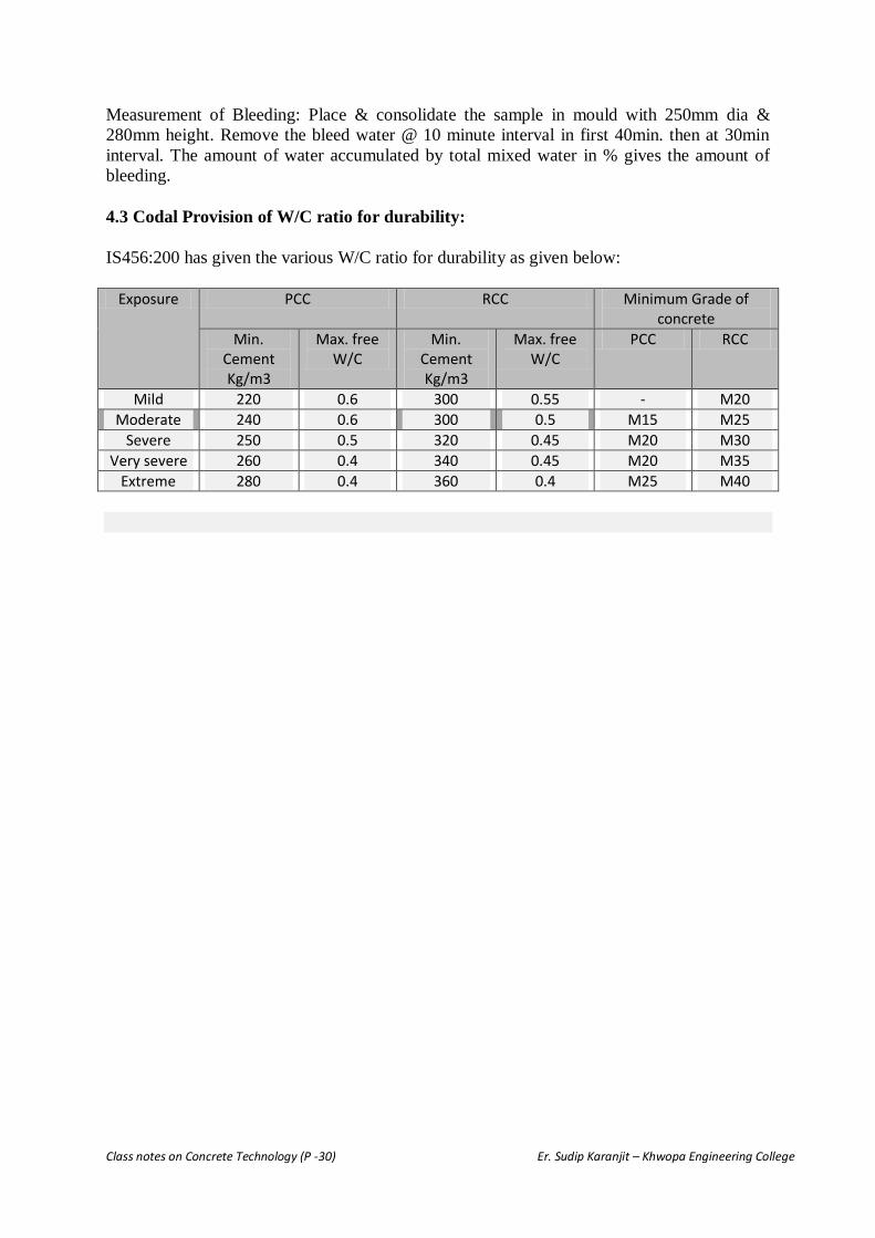
4.3 Codal Provision of W/C ratio for durability:
IS456:200 has given the various W/C ratio for durability as given below:
Exposure PCC RCC Minimum Grade of concrete
Min. Cement Kg/m3
Max. free W/C
Min. Cement Kg/m3
Max. free W/C
PCC RCC
Mild 220 0.6 300 0.55 - M20
Moderate 240 0.6 300 0.5 M15 M25
Severe 250 0.5 320 0.45 M20 M30
Very severe 260 0.4 340 0.45 M20 M35
Extreme 280 0.4 360 0.4 M25 M40

Class notes on Concrete Technology (P -31) Er. Sudip Karanjit – Khwopa Engineering College
5.0 ADMIXTURES
Admixture can be define as the ingredient other than cement/aggregate/water added to
concrete in order to achieve desired property of concrete as required. Can also be define as
the additives added to concrete so as to obtained the specific requirement of concrete.
Admixtures are mainly classified into two types:
i) Chemical admixture – These are the admixture containing basic ingredient as various
chemicals. Normally available in liquid / powder form. Use relatively low dosage
normally 0.04% to 5% by wt. of cement. Normally used to increase the workability,
to retard or accelerate the setting time/hardening process, for air entraining & water
proofing etc.
ii) Mineral admixtures – These are the admixture basically obtained from various natural
or artificial minerals. Normally available in finely divided power form. Its dose is
relatively higher than chemical admixture ranging from 10 – 80% by wt of cement.
Eg: Fly ash, blast furnance slag, silica fume, brick dust, stone dust etc. In many case
used as cement replacement ingredient due to its pozzolana property.
Ca(OH)2 in hydrated paste + POZZOLANA = C-S-H gel
4.1 Classification Of Admixtures:
ASTM Classification: ASTM C494 has specifies the various types of Chemical admixtures
as given below:
a) Type A: Water Reducing Admixture (Plasticizer)
Admixture which increase the workability of fresh concrete/mortar without increasing
water content or maintain workability with reduced water.
Can reduce water requirement by 5-12%
Dosage based on cement per 100kg (Eg, 200ml per 100kg {or 2bag} cement)
High dose may cause excessive retardation in setting time.
Eg: (Various lignosulphonate normally derived from wood product), (synthetic raw
materials), (polyglycol esters) etc.
b) Type B: Retarding Admixture.
Retarding Admixture delay the setting time of concrete / mortar.
Keep concrete workable for long period giving additional time for mixing, placing,
compacting & finishing.
Normally used to overcome unwanted effect of high temperature & to reduce slump-
loss.
Facilitates finishing in hot weather.
Eg: Calcium sulphate (gypsum), starch/sugar, cellulose, lignosulphonic-acid etc.
c) Type C: Accelerating Admixture.
Accelerating Admixture when added increase rate of hydration of hydraulic cement,
shorten setting time & increase hardening process.

Class notes on Concrete Technology (P -32) Er. Sudip Karanjit – Khwopa Engineering College
Normally used when fast setting & early strength gain is desirable (Eg, Urgent repair
work, road pavement construction etc)
Can be used in cold climate region for rapid strength gain.
Chloride is one of the economic/effective accelerating admixture but due to its action
on corrosion of steel its use is limited to 0.15% of Cement for RCC & 0.06% for
prestressed concrete.
Eg; Soluble carbonates, silicates & flurosilicates, Organic compound –
triethenolamine etc.
d) Type D: (A+B): Water Reducing & Retarding admixture.
Admixture which increase the workability & delay the setting time of concrete also.
Normally used when both water reducing & retarding action is desirable.
Widely used by “Ready mixed concrete” to facilitate long duration transportation,
mixing, placing & finishing & also to reduce slump-loss.
Eg; normally produced adding retarders to plasticizers, normally used retarders are
starch, gluconate etc.
e) Type E: (A+C): Water Reducing & Accelerating admixture.
Admixture which increase the workability & accelerate the setting time & hardening
of concrete also.
Normally used when both water reducing & accelerating action is desirable.
Suitable for urgent repairs.
Eg; triethenolamine-chloride, calcium nitrate, nitrites etc.
f) Type F: High Range Water Reducer (HRWR / Super-plasticizer).
Similar to plasticizing admixture with high water reducing capacity.
Normally used when high degree of water reduction is desirable.
Depending upon its type can reduce water content more than 30%.
Due to their powerful dispersing & fluidifying effect facilitates to work with very low
W/C ratio also.
HRWR normally available in market are: a) Sulphonated melanie-formaldehyde
(SMF), b) Sulphonated napthalene-formaldehyde (SNF), c) Carboxylate acrylic
easter, d) Other types.
Out of above listed HRWR Carboxylate polymer based superplasticisers are found
more effective & powerful.
g) Type G: (F+B): High Range Water Reducer & Retarding Admixture.
Admixture with both high range water reducing & retarding capability.
In addition to increase in workability, also prolong workability retention & retard
setting time.
Normally used when both high range water reducing & retarding action is desirable.
Widely used by “Ready mixed concrete” to facilitate long duration transportation,
mixing, placing & finishing & also to reduce slump-loss.
Eg; Produced by adding retarders to superplasticizers, normally used retarders are
starch, gluconate, cellulose, lignosulphonic acid etc.

Class notes on Concrete Technology (P -33) Er. Sudip Karanjit – Khwopa Engineering College
BIS Classification:
IS9103:1999 has specifies the various types of Chemical admixtures as given below:
a) Accelerating admixture.
b) Retarding admixture.
c) Water reducing admixture.
d) Air-entraining admixture:
Induce micro-air bubble (5 to 80µ) to concrete.
Used to produce air entrained concrete.
Air entraining admixture induce millions of fine uniformly distributed air bubble to
concrete.
These micro-air bubble acts as flexible ball bearing thus increase workability, reduce
segregation & bleeding, also the harden concrete have better resistance to freezing &
thawing.
Eg; Natural wood resin. Water soluble soap of resin acid, hydrogen petroxide,
aluminium power, Animal & vegetable oil etc.
e) Super-plasticizing admixture.
IS2645 – Specifies one more chemical admixture as:
f) Waterproofing Admixture.
Normally used where water impermeability is desirable.
Mainly two types:
Pore-filler: Reduce permeability by its pore-filling action. Normally used materials
are Chalk, Talc, Silicates, Aluminium power.
Water repellent: Prevent water penetration by its water repellent action. Normally
used materials are: Resin, vegetable oil, waxes, calcium soap, soda etc.
Mineral admixture like silica-fume, fly-ash & air entraining admixture can also used
to improve impermeability of concrete.
4.2 Effect of Admixtures in Concrete:
Effect on green (plastic stage) concrete:
Depending upon the types of the admixture as seen above the admixtures modify the property
of concrete in its green stage. Eg,
Plasticizer/super-plasticizer increases the workability/fluidity of mix, & also some retarding
effect depending upon its amount in concrete.
Accelerating admixture accelerate the hardening process while retarders slowdown the setting
process of concrete.
Air entraining admixture entrains the minute air bubble in concrete, reducing the negative
effect of segregation & bleeding.
Waterproofing admixture reduce the penetration of water through concrete by water repellent
action & reducing the permeability of concrete.
Mineral admixtures normally reduce the segregation & bleeding of concrete. Also in some
case reduce the water requirement for given workability.

Class notes on Concrete Technology (P -34) Er. Sudip Karanjit – Khwopa Engineering College
Effect on harden concrete:
Admixture shows both positive/negative effects on harden concrete.
Normally upto 3% no bad effect can be seen, but excessive addition shows retarding effect
(By plasticizer/super-plasticizer & air-entraining admixture) in both setting time & hardening
process of concrete.
Increase resistance to penetration thus durability to chemical deterioration is enhanced.
Higher creep with high W/C ratio but at low W/C ratio no effect is seen.
Drying shrinkage is not very much affected but in some case found improved.
Addition of mineral admixture shows improvement in durability & transition zone character
of concrete. But in some case delay in desired strength gain occurs due to slow hydration
process.
4.3 Local Materials as Admixtures in Nepal:
Present possibilities:
a) Rice husk ash
b) Calcined clay pozzolona (Brick dust / Burned clay dust)
c) Stone dust
Future possibilities with industrial development:
a) Silica fume
b) Fly ash
c) Blast furnace slag
d) Various chemical admixtures.
Mineral admixture: Fly ash, Blast furnace Slag, Rice husk ash, Silica fume, Brick /
stone dust. (Refer class note for detail)
Slump Loss & its prevention: (Refer class note)
Class notes on Concrete Technology (P -35) Er. Sudip Karanjit – Khwopa Engineering College
6.0 Mix Design of Portland Cement Concrete
Mix design is the process of determining relative quantity of concrete ingredients with the objective:
To ensure the desire workability of concrete at plastic stage (green stage).
To obtain the required strength, durability and surface finish at its hardened stage.
To achieve the economic mix.
6.1 Nominal & Design Mix of Concrete:
Nominal Mix: A concrete mix in which the proportions are adopted in generalized form irrespective
of its ingredient properties.
Design Mix: A concrete mix in which the proportions are adopted depending upon the ingredient
properties to obtain the desired workability, strength & durability of concrete.
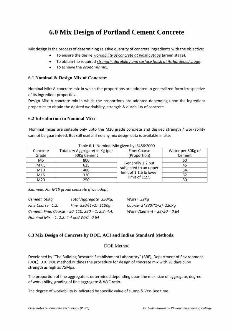
6.2 Introduction to Nominal Mix:
Nominal mixes are suitable only upto the M20 grade concrete and desired strength / workability
cannot be guaranteed. But still useful if no any mix design data is available in site.
Table 6.1: Nominal Mix given by IS456:2000
Concrete Grade
Total dry Aggregate( in Kg )per 50Kg Cement
Fine: Coarse (Proportion)
Water per 50Kg of Cement
M5 800 Generally 1:2 but
subjected to an upper limit of 1:1.5 & lower
limit of 1:2.5
60 M7.5 625 45 M10 480 34 M15 330 32 M20 250 30
Example: For M15 grade concrete if we adopt, Cement=50Kg, Total Aggregate=330Kg, Water=32Kg
Fine:Coarse =1:2, Fine=330/(1+2)=110Kg, Coarse=2*330/(1+2)=220Kg
Cement: Fine: Coarse = 50: 110: 220 = 1: 2.2: 4.4, Water/Cement = 32/50 = 0.64
Nominal Mix = 1: 2.2: 4.4 and W/C =0.64
6.3 Mix Design of Concrete by DOE, ACI and Indian Standard Methods:
DOE Method
Developed by “The Building Research Establishment Laboratory” (BRE), Department of Environment (DOE), U.K. DOE method outlines the procedure for design of concrete mix with 28 days cube strength as high as 75Mpa.
The proportion of fine aggregate is determined depending upon the max. size of aggregate, degree of workability, grading of fine aggregate & W/C ratio.
The degree of workability is indicated by specific value of slump & Vee-Bee time.

Class notes on Concrete Technology (P -36) Er. Sudip Karanjit – Khwopa Engineering College
Design Steps:
Step1: Determine target mean strength (Fmean) from specified characteristic strength(Fck):
Fmean = Fck+ σ* K
σ = Standerd deviation (IS456:2000 page23 – For M10/15=3.5, M20/25=4.0 M30-50=5.0)
K= Himsworth constant (1.64 for 95% confidence level)
Figure 6.1: Normal Distribution curve.
Step2: Determine Minimum W/C ratio based on Target Strength and compare with W/C
requirement for Durability consideration.
Fig: 6.2: Compressive strength vs W/C ratio
Table 6.2: Approximate compressive strength of
concrete with free water cement ratio W/C 0.5
1 2

Class notes on Concrete Technology (P -37) Er. Sudip Karanjit – Khwopa Engineering College
Table 6.3: Minimum Cement Content & Max. W/C for Durability:
Exposure PCC RCC Minimum Grade of concrete
Min. Cement Kg/m3
Max. free W/C
Min. Cement Kg/m3
Max. free W/C
PCC RCC
Mild 220 0.6 300 0.55 - M20
Moderate 240 0.6 300 0.5 M15 M25
Severe 250 0.5 320 0.45 M20 M30
Very severe 260 0.4 340 0.45 M20 M35
Extreme 280 0.4 360 0.4 M25 M40
Step3: Determine free water content depending upon max size & type of aggregate and degree of workability. Table 6.4: Approximate Water content (Kg/m3) for various degree of Workability:
Max. Size of Aggregate
mm
Slump 0-10 10-30 30-60 60-180
Vee-Bee >12 6-12 3-6 0-3
Aggregate Type
10 Uncrushed 150 180 205 225
Crushed 180 205 230 250
20 Uncrushed 135 160 180 195
Crushed 170 190 210 225
40 Uncrushed 115 140 160 175
Crushed 155 175 190 205
Step4: Calculate cement content from W/C ratio & water content of mix determined previously. Compare value with min. / max. value of cement content of durability requirement (Table 6.3) & modify if required. Step5: Determine wet density of concrete depending upon free water content & relative density of combine aggregate. Calculate Total aggregate content knowing the Wet density of concrete.
Fig: 6.3: Wet density of mix vs Free water content.

Class notes on Concrete Technology (P -38) Er. Sudip Karanjit – Khwopa Engineering College
Calculate total aggregate content (Saturated surface dry): γo-γc-γw
γo= Wet density of concrete (Kg/m3) γc= Cement Content (Kg/m3) γw= Free Water Content (Kg/m3) Step6: Determine Proportion of fine aggregate depending upon the W/C ratio, Max size of aggregate, fine aggregate grading zone & workability level.
Fine Aggregate =Total Agg. * Proportion of Fine Agg. Coarse Aggregate= Total Agg. – Fine Agg.
Fig: 6.4 Recommended % of fine aggregate in total aggregate vs W/C ratio. (Nominal max. size 20mm)
Fig: 6.5 Recommended % of fine aggregate in total aggregate vs W/C ratio. (Nominal max. size
40mm)

Class notes on Concrete Technology (P -39) Er. Sudip Karanjit – Khwopa Engineering College
EXAMPLE – DOE METHOD: Design concrete mix for RCC work for the moderate exposure
environment. The characteristic strength required is 30Mpa. Max aggregate size = 20mm crushed.
Sieve analysis of fine aggregate shows 50% passing through 600μ sieve. Average Sp. gr. of aggregate
is 2.65. Slump required 30-60 mm. OPC Cement (Type1) will be used.
Step1: Fmean = Fck+ σ* K = 30 + 1.64*5 = 38.2Mpa (For M30, σ =5 Ref; IS456:2000 page23)
Step2: Minimum W/C ratio based on Tar]\get Strength (Fig6.2 / Table 6.2) = 0.6
Minimum W/C ratio based on durability (Table 6.3) = 0.5
Adopt minimum W/C = 0.5
Step3: Free water content (Table 6.4) = 210kg/m3
Step4: Cement content (Step 2&3) = 210/0.5 = 420kg/m3 > min cement 300kg/m3 from Table 6.3
(OK)
Step5: Wet density of concrete for 210kg free water content & sp gr aggregate 2.65 (Fig 6.3) =
2375kg/m3
Total aggregate content = Total Concrete – Cement – Water = 2375 – 420 -210 = 1745kg/m3
Step6: % of fine aggregate (Fig 6.4 for slump 30-60 & W/C = 0.5 & FA 50% passing 600μ sieve.) = 35% of total aggregate
F A = 0.35 * 1745 = 610.75kg/m3
C A = 1745 – 610.75 = 1134.25kg/m3
Cement : Fine : Coarse = 420 : 610.75 : 1134.25 = 1 : 1.454 : 2.701

Class notes on Concrete Technology (P -40) Er. Sudip Karanjit – Khwopa Engineering College
ACI METHOD
The American Concrete Institute mix design method is suggested by the ACI Committee 211.
One method is based on the estimated weight of the concrete per unit volume & the other method is based on calculation of the absolute volume occupied by concrete ingredient.
This method consider the requirement for workability, consistency, strength and durability of concrete.
Design Steps:
Collect the data required for mix design first:
- Fineness modulus of fine aggregate, Sp. Gravity of fine & coarse agg. , Unit wt. of dry rodded
coarse agg. & Sp. Gr. of cement.
Step1: Determine target mean strength (Fmean) from specified characteristic strength(Fck):
Fmean = Fck+ σ* K
σ = Standerd deviation (IS456:2000 page23 – For M10/15=3.5, M20/25=4.0 M30-50=5.0)
K= Himsworth constant (1.64 for 95% confidence level)
Step2: Determine Minimum W/C ratio based on Target Strength and compare with W/C requirement for Durability consideration. Table 6.5: Relation between W/C ratio & Av. Compressive strength (ACI 211.1:91)
38.2 0.45

Class notes on Concrete Technology (P -41) Er. Sudip Karanjit – Khwopa Engineering College
Table 6.6: Relation between W/C ratio & Exposure conditions (ACI 318-89)
Step3: Determine free water content depending upon max size & type of aggregate and degree of workability.
Table 6.7: Water content determination depending upon slump & max. agg. size
Step4: Calculate cement content from W/C ratio & water content of mix determined previously. Step5: Determine Bulk volume of dry rodded C A depending upon Max. Agg. size & Fineness Modulus of fine aggregate (Table 6.8). Calculate Wt. of C A = Bulk Volume * Bulk Density

Class notes on Concrete Technology (P -42) Er. Sudip Karanjit – Khwopa Engineering College
Table: 6.8 Bulk Volume of Dry rodded Coarse Aggregate depending upon FM & Max Agg. size
Step6: Determine Wt. of Fresh concrete (Table 6.9) per m3: Table 6.9:
Wm = 10ρA(lOO-A)+ɣc(1-ρA/ ρC) -ɣw(ρA -1)
where
Wm = weight of fresh concrete, kg/m3 ρA = weighted average specific gravity of combined fine and coarse aggregate
ρC = specific gravity of cement (= 3:15)
ɣc = cement requirement, kg/m3
ɣw = mixing water requirement, kg/m3
A = air content, percent
Step7: Determine Wt of F A required:
F. A. (wt.) = Total wt of concrete (step6) – Cement (step4) – Water (step3) – C A (step5)
Now Mix proportion = Cement: FA: CA & W/C
OR

Class notes on Concrete Technology (P -43) Er. Sudip Karanjit – Khwopa Engineering College
EXAMPLE – ACI METHOD: Design concrete mix for RCC underground water tank. The characteristic
strength required is 30Mpa at 28days. Max aggregate size = 20mm crushed. Sieve analysis of fine
aggregate shows Fineness modulus 2.6. Dry rodded bulk density of CA = 1600kg/m3. Average Sp. gr.
of aggregate is 2.65. Slump required 30-60 mm. OPC Cement (Type1) will be used.
Step1: Fmean = Fck+ σ * K = 30 + 1.64*5 = 38.2Mpa (For M30, σ =5 Ref; IS456:2000 page23)
Step2: Minimum W/C ratio based on Target Strength (Table 6.5) = 0.45
Minimum W/C ratio based on durability (Table 6.6) = 0.5
Adopt minimum W/C = 0.45
Step3: Free water content (Table 6.4) = 185kg/m3
Step4: Cement content (Step 2&3) = 185/0.45 = 411kg/m3
Step5: Bulk volume of dry rodded C A = 0.64 {depending upon Max. Agg. Size 20mm & Fineness
Modulus of fine aggregate 2.6 (Table 6.8)}
Calculate Wt. of C A = Bulk Volume * Bulk Density = 0.64m3 * 1600kg/m3 = 1024 kg/m3
Step6: Wet density of concrete for Max 20mm aggregate & Normal Concrete (Table 6.9) =
2355kg/m3
Step7: Determine Wt of F A required:
F A required: = F. A. (wt.) = Total wt of concrete (step6) – Cement (step4) – Water (step3) – C A
(step5)
= 2355 – 411 - 185 – 1024 = 735kg/m3
Cement : Fine : Coarse = 411 : 735 : 1024 = 1 : 1.788 : 2.491
W/C = 0.45

Class notes on Concrete Technology (P -44) Er. Sudip Karanjit – Khwopa Engineering College
IS METHOD OF MIX DESIGN
This method is recommended by the Bureau of Indian standards covered in IS10262:1982. The method given can be applied from medium to high strength concrete. As the procedure developed in 1982 & since then lots of modification seen in concrete technology, code revision seems to be required. Design Steps:
Step1: Determine target mean strength (Fmean) from specified characteristic strength(Fck):
Fmean = Fck+ 1.65 * S
S = Standerd deviation (IS456:2000 page23 – For M10/15=3.5, M20/25=4.0 M30-50=5.0)
Step2: Determine Minimum W/C ratio based on Target Strength & Cement type, and compare
with W/C requirement for Durability consideration.
Fig: 6.6: Compressive strength vs W/C ratio
IS10262:82
Fig 6.7: Compressive strength of concrete various
cement type IS10262:82

Class notes on Concrete Technology (P -45) Er. Sudip Karanjit – Khwopa Engineering College
Fig 6.7: Compressive strength of concrete various cement type (Germany)
Table 6.10: Minimum Cement Content & Max. W/C for Durability (IS456:2000):
Exposure PCC RCC Minimum Grade of concrete
Min. Cement Kg/m3
Max. free W/C
Min. Cement Kg/m3
Max. free W/C
PCC RCC
Mild 220 0.6 300 0.55 - M20
Moderate 240 0.6 300 0.5 M15 M25
Severe 250 0.5 320 0.45 M20 M30
Very severe 260 0.4 340 0.45 M20 M35
Extreme 280 0.4 360 0.4 M25 M40
Step3: Determine free water content & Fine to total Agg. ratio depending upon max size of aggregate & concrete Strength for standard condition.
Make the adjustment depending upon Ingredient properties.
Table 6.11: Approximate Sand & Water content (Kg/m3) for Compaction Factor CF =0.8 (approximate slump 30mm), Angular coarse aggregate & Sand zone II as per IS383:1970
Upto M35 W/C - 0.6
CF =0.8
> M35 W/C – 0.35
CF =0.8

Class notes on Concrete Technology (P -46) Er. Sudip Karanjit – Khwopa Engineering College
Table 6.12: Adjustment table for water content & % sand in total aggregate.
Step4: Calculate cement content from W/C ratio & water content of mix determined previously. Compare value with min. / max. value of cement content of durability requirement (Table 6.10) & modify if required. Step5: Calculate Aggregate content:
Step6: The mix proportion above obtained by the assumption that the aggregates are saturated & surface dry if any deviation, make adjustment in water & aggregate content.

Class notes on Concrete Technology (P -47) Er. Sudip Karanjit – Khwopa Engineering College
EXAMPLE – IS METHOD: Design concrete mix for RCC Silo. The characteristic strength required is
30Mpa at 28days. Max aggregate size = 20mm crushed. Sieve analysis of fine aggregate shows Sand
zone III. Workability required compaction factor 0.9. Exposure condition moderate. Cement Type E -
53Mpa will be used. Sp. gr. of CA = 2.7 / FA = 2.6 / Cement = 3.15.
Step1: Fmean = Fck+ 1.65*S = 30 + 1.65*5 = 38.25Mpa (For M30, σ =5 Ref; IS456:2000 page23)
Step2: Minimum W/C ratio based on Target Strength (Fig 6.7) = 0.45
Minimum W/C ratio based on durability (Table 6.10) = 0.5
Adopt minimum W/C = 0.45
Step3: Free water content (Table 6.11) = 186kg/m3 & F A = 35% of Total Agg.
Adjustments (Table 6.12):
Condition Change Water Content % adjustment Sand content % Adjustment
Sand confirming Zone III 0 - 1.5%
Increase in Compaction Factor
(0.9-0.8) = 0.1 + 3% 0
Decrease in W/C ratio (0.45-0.6)
= -0.15 0
- (0.15/0.05)
= - 3%
Total +3% -4.5%
F A content = 35 -4.5 = 30.5%
Water content =186 +3% *186 = 191.6kg
Step4: Cement content (Step 2&3) = 191.6/0.45 = 425.8kg/m3 > 240kg ok
Step5: Calculate Aggregate content:
(1 − 0.02) = 191.6 +425 .8
3.15+
𝑓𝑎
.305∗2.6 ∗
1
1000
fa = 518kg/m3
𝐶𝑎 =1−0.305
0.305∗ 518 ∗
2.7
2.6
Ca= 1225.8kg/m3
Cement : Fine : Coarse = 425.8 : 518 : 1225.8 = 1 : 1.217 : 2.879 & W/C = 0.45
Air content

Class notes on Concrete Technology (P -48) Er. Sudip Karanjit – Khwopa Engineering College
7.0 STRUCTURE & STRENGTH OF CONCRETE
7.1 Concrete as 3-Phase System & Structure Of Different Phases:
Refer “Structure of Hydrated Cement / Three phase system of Concrete” - page 17 of this note:
7.2 Strength Porosity Relationship Of Concrete:
Strength of concrete is primarily depends upon the strength of cement paste. Many research
has shown that strength of cement paste depend on the W/C ratio used. Abrams presented his
W/C rule in 1918 as:
S= A/B x Where, x = w/c ratio; A=14000lbs/sqin; B= 7 for 28 days compressive strength.
Abrams w/c law states that the strength of concrete depends on the w/c ratio only. This rule is
still taken as the fundamental tool for concrete mix design. This rule explains the weakening
of paste phase due to increase in W/C ratio thus porosity of concrete but effect of W/C ratio
in transition zone is not explained.
Also the effect of aggregate strength on concrete is not incorporated in the rule (assuming the
aggregates are stronger than paste & concrete failure takes place with bond failure only,
which may not be true always).
Feret has formulated the strength of concrete paste depending upon its constituents in 1897
as,
Strength S = K*[𝒄
(𝒄+𝒆+𝒂)]2
c, e & a – Volume of cement, water & air respectively.
Equation given by Feret explain the strength change not only due to the effect on w/c ratio
but also the degree of compaction (a-air content).
Gel-Space ratio:
Many research has shown that the strength parameter can be related more accurately to the
gel-space ratio than the w/c ratio. Power & Brownyard presented that the gel-space ratio
(Ratio of solid product of hydration of cement to space available for product formation).
The gel-space ratio can also be defined as the ratio of volume of hydrated cement paste to
sum of volume of hydrated paste & capillary pores.
Strength S = 240*x3
Where x= gel space ratio.
Calculation of gel-space ratio:
C= wt. of cement in gm
Vc=Sp. Volume of cement = 0.319ml/gm
Wo = Volume of water
It was presented by various researches that 1gm cement produce nearly 2.06ml of gel.

Class notes on Concrete Technology (P -49) Er. Sudip Karanjit – Khwopa Engineering College
Assuming 1ml cement produce 2.06ml gel.
Volume of gel = Volume of Cement * 2.06 = (C* Vc) *2.06 = 2.06 C* Vc
Total Space available = Vol. of Cement + Vol. of Water = (C* Vc + Wo)
Gel Space ratio = Vol. of gel / Total Space available = 2.06 C Vc /( C Vc +Wo)
If cement hydrates by α% only;
Gel Space ratio (x) = (𝟐.𝟎𝟔 𝐂𝐕𝐜 𝛂%)
(𝐂𝐕𝐜 𝛂%+𝐖𝐨) 𝒐𝒓
(𝟐.𝟎𝟔 𝐕𝐜 𝛂%)
(𝐕𝐜 𝛂%+𝐖/𝐂)
If 1ml cement produce 2ml gel,
Gel Space ratio (x) =(𝟐.𝟎 𝐂𝐕𝐜 𝛂%)
(𝐂𝐕𝐜 𝛂%+𝐖𝐨) 𝒐𝒓
(𝟐.𝟎 𝐕𝐜 𝛂%)
(𝐕𝐜 𝛂%+𝐖/𝐂)
Strength S = 240*x3
(N/mm2)
Capillary porosity= Capillary void/ Total space =(𝑻𝒐𝒕𝒂𝒍 𝒔𝒑𝒂𝒄𝒆−𝒗𝒐𝒍𝒖𝒎𝒆 𝒐𝒇 𝒔𝒐𝒍𝒊𝒅)
(𝑻𝒐𝒕𝒂𝒍 𝒔𝒑𝒂𝒄𝒆)
Total space = (Volume of cement + volume of water) = (CVc+Wo)
Volume of solid = (volume of cement unhydrated + volume of gel from hydrated cement)
If cement hydrates by α% ;& 1ml cement produce 2.06ml gel.
Volume of solid = C Vc (1-α) + 2.06 CVc α
Capillary porosity = (𝑻𝒐𝒕𝒂𝒍 𝒔𝒑𝒂𝒄𝒆−𝒗𝒐𝒍𝒖𝒎𝒆 𝒐𝒇 𝒔𝒐𝒍𝒊𝒅)
(𝑻𝒐𝒕𝒂𝒍 𝒔𝒑𝒂𝒄𝒆) =
(𝐖/𝐂− 𝟏.𝟎𝟔 𝐕𝐜 𝛂%)
(𝐕𝐜+𝐖/𝐂)
If 1ml cement produce 2ml gel,
Capillary porosity = (𝐖/𝐂− 𝐕𝐜 𝛂%)
(𝐕𝐜+𝐖/𝐂)
7.3 Various Types Of Strength Of Concrete & Their Inter-Relationship:
i) Compressive Strength:
Compressive strength is taken as the one of the most important parameter of concrete. As
most of its other properties are also related to the compressive strength & also the concrete is
commonly employed to resist the compressive strength, its knowledge is primary importance
to all.
Normally compressive strength is determined by two method:
a) Cube compressive strength: Compressive strength of standard cube (normally taken as
150x150x150mm). It shows that the smaller size cube give relatively higher strength
value than bigger size. Typical test result is given below:

Class notes on Concrete Technology (P -50) Er. Sudip Karanjit – Khwopa Engineering College
Size effect of cube test (cube other than standard):
Cube size (mm) 100 150 200 300
Relative Strength 1.05 1.00 0.95 0.87
b) Cylinder compressive strength: Compressive strength of standard cylinder (normally
150mm dia. X 300mm ht – ht. to dia. ratio = 2). It is found that the ratio of ht. to dia.
other than 2 (standard size) affect the cylinder strength as given below:
Effect of height to diameter ratio on cylinder strength:
As cylinder specimen seems to have more uniform result than cube specimen, is being
popular in research laboratory. But due to easiness in casing & transportation cube specimen
are popular in construction site in country like Nepal, India, UK etc.
It is found that the cylinder specimen gives lower strength value than cube strength. Various
relations between cube & cylinder strength are given below:
BS 1881:1970 ;
Cylinder strength = (4/5)* Cube Strength
L Hermite;
Cylinder strength = 0.76+0.2*log(fcm/2840) Here, fcm =cube strength lbs/sqin
Typical test result:
Cube Strength (Mpa) 9 20 30 45 49
Cylinder Strength (Mpa) 7 17 27 42 45
ii) Tensile Strength: Being weak in tension, tensile strength of concrete is normally
neglected in design. Various test method / tensile strengths are given below:
a) Direct tension: If tensile strength of concrete is determined applying direct (Pure) tension
to concrete specimen.
Tensile Strength (fct) = Tensile Force (P)/Area
P P

Class notes on Concrete Technology (P -51) Er. Sudip Karanjit – Khwopa Engineering College
As perfect grip during loading is difficult & also due to induction of secondary
stress, the direct tensile test is not very popular. Normally tensile strength of
concrete can be taken as 10% of compressive strength (Fck).
IS456:2000 relates direct tensile strength to compressive strength as:
Tensile Strength (𝒇𝒄𝒕) = 𝟎.𝟑𝟓 ∗ 𝑭𝒄𝒌
b) Splitting tension: This is one of the popular indirect tensile test method also known as
Brazilian test. The test is carried out in cylinder specimen, placing it horizontally between
loading surface. Even the load applied is compressive; almost 5/6th of depth is subjected
to uniform tensile stress. Splitting tensile test gives slightly higher value than direct
tension.
Horizontal Tensile Stress = 2P/π LD
P = Compressive Load (N)
L= Length of Specimen (mm)
D= Diameter of Specimen (mm)
Vertical compressive Stress on cylinder = 2P/π LD ∗ [ 𝑫𝟐
𝒙 𝑫−𝒙 −𝟏]
c) Flexural tension: Flexural tension is the tensile force developed in concrete in bending.
As most of the concrete element has to resist bending tension instead of direct tension, the
flexural tension has also its own importance. Normally two types of flexural test is
performed to determine flexural tension:
i) Center point loading
ii) Three point loading
D-x
x

Class notes on Concrete Technology (P -52) Er. Sudip Karanjit – Khwopa Engineering College
In given figure below, at any section:
б = M/I * y
Where,
б = Stress at distance y from neutral axis (NA)
M= Moment at given section of beam for given loading.
I= Moment of Inertia of section (For rectangular section = bd3/12)
y= Distance at which stress is required (For rect. section at extreme fiber =d/2)
The standard test specimen size for above test is 15x15x70cm (Span L =60cm) alternatively
10x10x50cm (Span L=40cm) specimen is also used in some case. The flexural strength of
specimen is determined as modulus of rupture fb (= бmax) at ultimate loading.
Test result shows that center pt. loading gives slightly high value than 3 point loading;
following empirical relation is given by center of road research,
fb (Centre pt. loading) = fb (3 pt. loading) + 0.72 fb= flexural strength (in Mpa)
IS456:2000 relates modulus of rupture (Flexural tension) to compressive strength as:
Flexural tensile strength (𝒇𝒃) = 𝟎.𝟕 ∗ 𝑭𝒄𝒌
iii) Shear Strength: Shear can be defined as the action of equal & opposite parallel force
acting in plane short distance apart. Direct determination of shear force is difficult, can be
taken as 12% of compressive strength if test data is not available. In beam shear failure
can be seen as combine bending & shear, normally acting at 450 to shear.
IS456:2000 relates Shear strength to compressive strength as:
Compressive strength M15 M20 M25 M30 M35 M40
Shear strength (N/mm2) 1.6 1.8 1.9 2.2 2.3 2.5
iv) Bond strength: In generalized form two types of bond strength can be discussed:
a. Bond between cement & aggregate: Bond between hydrated cement & aggregate affects
the overall strength of concrete. As for normal strength concrete aggregate is sufficiently
strong the strength of concrete depends entirely upon the bonding between cement &
aggregate. Lower W/C ratio & use of mineral admixture significantly enhance the bond
strength by reducing porosity & enhancing characteristics of transition zone.
T
C NA

Class notes on Concrete Technology (P -53) Er. Sudip Karanjit – Khwopa Engineering College
b. Bond between steel & concrete: This bond is primarily due to the friction & adhesion
between steel & concrete surface. Mainly depends upon the strength of concrete &
surface and mechanical property of steel. Higher the compressive strength higher will be
the bond strength. Higher specific surface of gel also found to give higher bond strength
(C-S-H gel from C2S gives more sp. surface than from C3S compound). Also the
deformed bar has found to give higher bond strength than plain bar. The moisture content
(adversely affect) & stress condition (In tension low bond strength – in compression high)
also affect the bond strength.
IS456:200 has given the bond strength of plain bar in tension as:
Compressive strength M15 M20 M25 M30 M35 M40
Bond strength (N/mm2) 6 8 9 10 11 12
For deformed bar above value can be increased by 60%
Further increase in above value for bar in compression by 25%
v) Bearing strength: Concentrated loading on concrete surface tends to punch the surface
inside, resistance to which can be termed as bearing strength. Normally, bearing stress is
significant at the base of the steel/concrete column in foundation & in anchored area of
tendon in pre-stressed concrete. IS 456:2000 recommends,
Bearing Strength = 0.25*Fck for Working stress design method.
Bearing Strength = 0.45*Fck for Limit State design method.
7.5 Effect Of Time & Temperature On Concrete: As we know the hydration of cement
continues for long course of time, provided the moisture available for hydration process;
strength of concrete also increases in similar pattern with time. In general, strength of
concrete increases with time.
ACI -209 recommends the following
relationship to determine compressive strength
at any time ,
fcm (t) = fc28* 𝒕
(𝟒+𝟎.𝟖𝟓𝒕)
CEB-FIP Model Code (1990) recommends:
fcm (t)= Exp [S (1- (𝟐𝟖
𝒕/𝒕𝟏) )]* fc28
fcm (t)= Sterngth at any time t; fc28 = 28 days strength
S= 0.2 (Early strength cement); S= 0.25(Normal OPC) ; S= 0.38 (Slow hardening cement);
t=time in day; t1= 1day
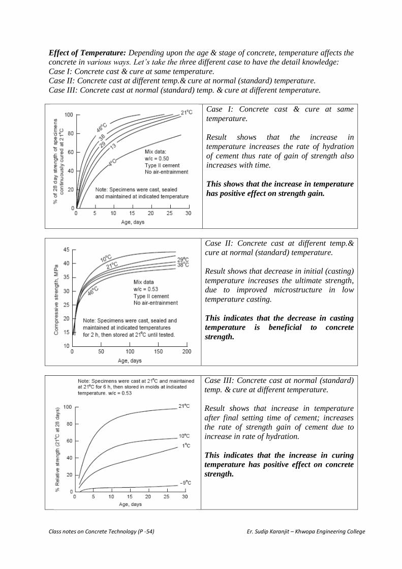
Class notes on Concrete Technology (P -54) Er. Sudip Karanjit – Khwopa Engineering College
Effect of Temperature: Depending upon the age & stage of concrete, temperature affects the
concrete in various ways. Let’s take the three different case to have the detail knowledge:
Case I: Concrete cast & cure at same temperature.
Case II: Concrete cast at different temp.& cure at normal (standard) temperature.
Case III: Concrete cast at normal (standard) temp. & cure at different temperature.
Case I: Concrete cast & cure at same
temperature.
Result shows that the increase in
temperature increases the rate of hydration
of cement thus rate of gain of strength also
increases with time.
This shows that the increase in temperature
has positive effect on strength gain.
Case II: Concrete cast at different temp.&
cure at normal (standard) temperature.
Result shows that decrease in initial (casting)
temperature increases the ultimate strength,
due to improved microstructure in low
temperature casting.
This indicates that the decrease in casting
temperature is beneficial to concrete
strength.
Case III: Concrete cast at normal (standard)
temp. & cure at different temperature.
Result shows that increase in temperature
after final setting time of cement; increases
the rate of strength gain of cement due to
increase in rate of hydration.
This indicates that the increase in curing
temperature has positive effect on concrete
strength.

Class notes on Concrete Technology (P -55) Er. Sudip Karanjit – Khwopa Engineering College
7.6 Importance of Curing (Effect of humidity):
Various research/test data shows that the continuously moist cured concrete gives almost 2 to
3 times greater ultimate strength than entire air cured concrete. The decrease in strength of air
cured concrete is due to loss of moisture, which ultimately interrupt the hydration process of
cement. Loss of moisture thus strength gain mainly depends upon the exposed surface area &
temperature/humidity condition of surrounding & also some extent to thickness &
permeability of concrete. Normally minimum 7 days moist curing is recommended for
satisfactory result. For fly ash or slag cement long term curing is required than OPC. The
figure shows the effect of curing on strength gain.
7.7 Effects Of Cyclic & Dynamic Loads on Strength:
Cyclic loading: Any type of repeated loading on structure can be termed as cyclic loading.
Due to fatigue behavior of material repeated loading at high stress level affects negatively on
the strength. Many researchers had shown that at stress level greater than 50% of
compressive strength of concrete, cyclic loading has an adverse effect on concrete strength.
Typical test indicates that; at 5000 cycle of repeated loading concrete fails only at 70% of its
ultimate monotonic strength. Progressive micro-cracking at interfacial transition zone and
paste matrix are main cause of this strength degradation.
For stress level 50-75% of fc, gradual degradation in both characteristic strength (Fck) &
modulus of elasticity (E) occurs.
Gradual increase in cycle shows distinct nonlinear behavior of concrete in cyclic loading.

Class notes on Concrete Technology (P -56) Er. Sudip Karanjit – Khwopa Engineering College
The relation between max stress level & number of cycle for failure can be given as:
fc = Strength at static loading.
fmax = Max. Stress in cycle.
John Hanson has given the following relation for 95% confidence level:
𝑳𝒐𝒈 𝑵 =(𝟏 −
𝒇𝒎𝒂𝒙𝒇𝒄 )
𝜷(𝟏 −𝒇𝒎𝒊𝒏𝒇𝒎𝒂𝒙)
− 𝟏.𝟗
fmin = Min. stress in cycle.
𝜷 = 0.0685
Another relation by Kakatuwa:
𝑳𝒐𝒈 𝑵 =𝟏𝟕 (𝟏 −
𝒇𝒎𝒂𝒙 − 𝒇𝒎𝒊𝒏𝒇𝒄 )
(𝟏 −𝒇𝒎𝒊𝒏𝒇𝒄 )
Dynamic/Impact Loading: If concrete is applied with very short term loading can be termed
as impact loading. In other word, if the rate of loading applied is very high can be termed as
impact loading and strength under such loading condition is termed as impact strength. It is
interesting that the impact strength of concrete increases with rate of loading (i.e. Higher the
impact rate higher the strength of concrete).
Compare to the 0.25Mpa/sec of standard loading condition, the lower rate (0.007Mpa/sec)
shows 12% reduction in fck, while increased loading rate (6.9Mpa/sec) shows 12% increase
in fck. Due to the availability of time for the propagation of micro-crack (in transition zone)
at low rate of loading, high loading rate shows improved strength value.
Impact strength found to be increased with:
Increase in rate of loading.
Increase in surface roughness of aggregate.
Decrease in aggregate size.
Improved transition zone.
Increase in tensile strength of concrete.
fmax / fc
Log N
Class notes on Concrete Technology (P -57) Er. Sudip Karanjit – Khwopa Engineering College
The CEB-FIP Model Code (1990) recommends the following relation for compressive
strength due to impact:
𝑓𝑐 ,𝑖𝑚𝑝
𝑓𝑐= (𝜎𝑠 / σ0 )𝜶
Where,
fc,imp = impact compressive strength
fc = compressive strength of concrete,
σ0 = −1.0 MPa/s
σs = impact stress rate
α = 1/(5 + 9 fc/fo); fo = 10 MPa

Class notes on Concrete Technology (P -58) Er. Sudip Karanjit – Khwopa Engineering College
8.0 Dimensional Stability of Concrete
8.1 Non-linear stress-strain relation & modulus of elasticity of concrete:
Stress-strain curve of concrete shows its distinct non linear behavior even at lower stress
level. Even the cement paste & aggregate shows linear behavior at its initial loading stage (as
shown in fig below), being heterogeneous & multiphase material stress strain curve of
concrete shows non-linear behavior even at the beginning. The fig below also indicates that
the properties of concrete is not equal to sum of properties of its components.
Experiment shows that stress strain curve of rich mix concrete shows less strain value for
particular stress level also the ultimate strain is less (ie low ductility behavior).
Behavior of concrete (in terms of Stress-strain curve & failure mechanism) at various stress
level can be expressed as given below.
At initial stage of loading upto 30% of ultimate stress level, concrete shows stable system of
micro-cracking. Micro crack exist in transition zone only & stress strain curve also shows its
linear behavior.

Class notes on Concrete Technology (P -59) Er. Sudip Karanjit – Khwopa Engineering College
Upto 30-50% of ultimate stress level, increase in both length & width of micro-cracks occurs
in transition zone. Still the micro-crack system can be termed as stable & normally no crack
in paste phase but stress-strain curve begin to show its non linearity.
Upto 50-75% of ultimate loading crack start in paste phase also. Further propagation of crack
in both transition zone & paste matrix leads crack system to unstable stage. Stress strain
curve shows strong non-linearity.
Upto 75-100% of ultimate loading crack reach at its critical stage & with the increase in crack
spontaneous failure of specimen occur at its ultimate loading. Stress strain curve almost
become flat & moves down indicating failure.
Modulus of elasticity (E) :
Even for the non-linear material like concrete, determination of modulus of elasticity is really
important for any type of structural analysis & to know the load deflection behavior of any
structural system.
As shown above response of concrete to applied loading is quite complex & stress strain
curve also shows its non-linear behavior even at low stress level.
Due to its non-linear behavior there exists different E value at different stress level. Different
types of modulus of elasticity, depending upon its mode of determination can be given as:
a. Initial tangent modulus (Dynamic
modulus): If the E – value is determined
by drawing tangent at beginning of curve,
is termed as Initial tangent modulus. This
is only suitable for low stress level.
b. Tangent modulus: If modulus of elasticity
is determined by drawing tangent at any
point in curve, is termed as tangent
modulus. This is only suitable for stress
level near to that point.
c. Secant Modulus: If modulus of elasticity is
determined by joining any point in curve
to origin, is termed as secant modulus.
This is one of the widely used method for
determination of E.
d. Chord modulus: If modulus of elasticity is determined by joining any two point in
curve, is termed as chord modulus. This is mainly used for typical research purpose
only.
Normally modulus of elasticity can be determined in lab by:
Gradual loading to cylinder or cube specimen in uniaxial compression & noting series
of stress-strain value for given loading values.

Class notes on Concrete Technology (P -60) Er. Sudip Karanjit – Khwopa Engineering College
Flexural modulus: Can also be determined by subjecting a concrete beam to bending
(loading can be the point load on middle or any other arrangement) & using the
defection relation derived in structural theory.
E= PL3/48IΔ (For pt. load at middle of span)
Dynamic modulus: Determined by subjecting concrete specimen to longitudinal
vibration at their its natural frequency & applying relation:
Ed = K n2 L
2 ρ ρ= Density of concrete
L= Specimen length mm
n= Resonating frequency HZ
K= 4x10-15
(Gpa)
Factor affecting E:
Strength of concrete (Directly proportional-
E=5000 𝑭𝒄𝒌 𝒂𝒔 𝒈𝒊𝒗𝒆𝒏 𝒃𝒚 𝑰𝑺𝟒𝟓𝟔:𝟐𝟎𝟎𝟎)
Moisture condition (Ewet > Edry)
Aggregate / Paste quality (1/E = Vol. of paste/E paste + Vol. of Agg/E Agg)
Poisson ratio µ:
Can be define as the ratio of lateral strain to corresponding longitudinal strain.
µ = 0.15 – 0.2 for most of the concrete.
Generally high for low strength concrete & low for high strength
For analysis & design of some typical structure its knowledge is required.
Ultrasonic pulse velocity method can be applied as alternative method to find out its value.
(𝑽𝟐/𝟐𝒏𝑳)𝟐 = (𝟏 − 𝝻)
(𝟏 + 𝝻 )(𝟏 − 𝟐𝝻 )
L= Specimen length mm
n= Resonating frequency HZ
V= Pulse velocity (mm/s)
8.2 Durability of concrete:
Ability of concrete to resist any type of deterioration (Eg. Weathering, abrasion, chemical
attack etc.) can be termed as durability.
Can also be defined as the ability to retain its original form, quality & serviceability when
exposed to environment.

Class notes on Concrete Technology (P -61) Er. Sudip Karanjit – Khwopa Engineering College
For the durability of concrete permeability is treated as one of the key factor. Being small,
water molecules are capable of penetrating extremely fine pores / cavities. As a one of the
strong solvent it may dissolve acid/salt/alkalis/gas – ions which ultimately cause the
deterioration of concrete. For the same reason less the permeability of concrete less the effect
of chemical deterioration to it.
Cause of deterioration:
Physical / Mechanical Cause
Chemical Cause
Check the class note – in tabulated format for detail.
Characteristics of concrete influencing durability:
Permeability to water, O2, CO2, Chloride, Sulphate, & other potentially deteriorating
substances.
W/C ratio.
Cement type.
Compaction & Curing .
Rate of hydration & hydration process.
8.3 Creep & shrinkage phenomenon:
Creep is the time dependent strain phenomenon of concrete.
Creep can be defined as the gradual increase in strain with time even at sustained loading
condition. Cement paste plays important role in creep phenomenon. Even it is matter of
further research, creep is said to be due to the movement of gel & paste water in concrete by
various internal & external condition & at sustained loading.

Class notes on Concrete Technology (P -62) Er. Sudip Karanjit – Khwopa Engineering College
Creep is partially reversible & partially irreversible phenomenon. The permanent deformation
due to creep is also called residual deformation.
Factors affecting creep:
Aggregate properties: Stronger the aggregate less the effect of creep. Aggregate with
higher E-value shows less creep.
Mix Proportion: Rich mix concrete with low W/C ratio shows low creep than poor
concrete mix.
Age/Time: Higher the age of concrete, more the formation of gel which ultimately
reduce creep phenomenon.
Shrinkage:
Change in volume of concrete by various phenomenon is called shrinkage. Shrinkage in
concrete is mainly due to the loss of moisture from concrete at its various stages. Various
types (as well as cause) of shrinkage can be listed as:
a) Plastic Shrinkage: Shrinkage due to the loss of moisture of concrete at its plastic stage
(green stage) is called plastic shrinkage. This type of shrinkage can be seen more in
large exposed surface concrete eg, road pavement, floor slab etc. Moisture loss due to
evaporation is main cause of this type of shrinkage.
b) Drying Shrinkage : Shrinkage due to the loss of moisture of harden concrete is called
drying shrinkage. Due to loss of moisture from concrete subjected to drying condition,
drying shrinkage occurs.
c) Autogeneous Shrinkage: Shrinkage due to without moisture movement from or to
concrete system can be termed as Autogeneous shrinkage. Very negligible compared
to other types of shrinkage.
d) Carbonation Shrinkage: CO2 present in environment react with Ca(OH)2 in concrete
producing CaCO3. This leads to the volume change in concrete, resulting carbonation
shrinkage.
8.4 Thermal properties of concrete: Check the class notes.